Minimum-Quantity Cooling and Lubricating System Operating ...
44
INDUTEC ® MS Minimum-Quantity Cooling and Lubricating System Operating Instructions
Transcript of Minimum-Quantity Cooling and Lubricating System Operating ...

INDUTEC ® MSMinimum-Quantity Cooling and Lubricating System
Operating Instructions

INDUTEC ® MS
INDUTEC ® MS Designation of the indicating and operating elements
Designation of the indicating and operating elements
Filling opening (medium) with
forced exhaust
3/2-way solenoid valve (spraying air)
Pressure control valve
Pressure gauge (vessel pressure)
12
Throttle valve (spraying air)
Throttle valve (Medium)
Swivel-ring piece (control air)
As of 1st of June 2005
All rights reserved. Duplication, translation, microfilming and and storage in electronic media, particularly for commercial purposes, are prohibited without the consent of the publisher.
Subject to technical changes in the interest of improing the system and its individual parts in conformity with its intended purpose.
Editor: Layout and text: MENZEL METALLCHEMIE GMBH com.units GmbH Im Gewerbepark 14 Eichwiesenring 10 73329 Kuchen 70567 Stuttgart Germany Germany
1
3
4
5
7
8
9
Shutt-off valve (medium)
14
16
15
17
18
11
10
Safety valve
Filling level indicator
3/2-way solenoid valve (control air)
Shutt-off valve (air)
compressen air connector
Pressure control valve (spraying air)
Pressure gauge (spraying air)
20 Filter with rising pipe

INDUTEC ® MSINDUTEC ® MS
INDUTEC ® MSINDUTEC ® MS
3
Foreword
Foreword
Dear INDUTEC® MS user,
Minimum-Quantity Cooling and Lubricating System will enable you to use eco-friendly coolants and lubricants and reduce the actual amounts used to a minimum, thereby avoiding the associated hazardous waste. Depending upon the given application, the INDUTEC® MS Minimum-Quantity Cooling and Lubricating System will lengthen the serv-ice life of your tools and secure a clean work environment. These Operating Instructions provide all the necessary information for the transportation,
installation, operation, maintenance and repair of the INDUTEC® MS Minimum-Quantity Cooling and Lubricating System.
With this INDUTEC® MS Minimum-Quantity Cooling and Lubricating System you have acquired a technical system that is subject to special safety rules for its operation.Consequently, it is imperative that all persons working in any way with parts of the system, or with the complete system (e.g. operation, maintenance or transport), must first study these Operating Instructions carefully before starting to work, and operate the system accordingly.
These Operating Instructions must be accessible at all times at the point of operation of the INDUTEC® MS Minimum-Quantity Cooling and Lubricating System.
Please do not hesitate to contact our Customer Service if you have any questions which go beyond these Operating Instructions. We are at your service at all times for questions and information.
These Operating Instructions and all illustrations are based on the latest technical standards of the INDUTEC® MS Minimum-Quantity Cooling and Lubricating System at the time they went to print. Deviations of your System from the illustrated modules are the result of technical modifications made for the constant improvement of the System. A revised edition of these Operating Instructions is published when the changes are extensive. If the configuration of the System has been extended by accessory parts that are not described in these Operating Instructions, then please refer to the correspond-ing instructions supplied with the accessories. System operation in conformity with its intended purpose (see Ch. 2.2) is unaffected by technical deviations and the accesso-ries used.

4
INDUTEC ® MS
INDUTEC ® MS
INDUTEC ® MSINDUTEC ® MS
INDUTEC ® MSINDUTEC ® MS
5
1 Introduction 6
1.1 Important remarks concerning the Operation of the INDUTEC® MS Minimum-Quantity Cooling and Lubricating System 6
2 Safety rules 7
2.1 Symbols 7
2.2 Use in conformity with the intended purpose 8
2.3 Hazards due to electrical energy 9
2.4 Hazards due to medium-air mixture 10
2.5 Hazards due to a failure of the compressed-air system 11
3 Functional principal 12
4 Transport and storage 13
4.1 Transport 13
4.2 Storage 13
5 Installation and setting into operation 14
5.1 Modules of the INDUTEC® MS Minimum-Quantity Cooling and Lubricating System 14
5.2 Assembly 17
5.3 Installing the pressure vessel 18
5.4 Installing the valve unit 23
5.5 Installing the coaxial spraying heads 27
5.6 Starting up the System 30
6 Maintenance and repair 35
6.1 Cleaning 35
6.2 Trouble-shooting 37
7 Shutting down 39
8 Technical data 40
8.1 Dimensions 40
8.2 Sealing materials 41
9 Manufacturer‘s declaration 42
Content

6
INDUTEC ® MS
INDUTEC ® MS
1 Introduction
1.1 Important remarks concerning the Operation of the INDUTEC® MS Minimum-Quantity Cooling and Lubricating System
All work with or on the INDUTEC® MS Minimum-Quantity Cooling and Lubricating System is subject to the statutory „Safety and Accident Prevention Rules“, quite independent of any remarks made in these Operating Instructions.
It is imperative that all persons working in any way with parts of the system, or with the complete system (e.g. operation, maintenance or transport), must first study these Oper-ating Instructions carefully, particularly the chapter „Safety Rules“ before they start work and operate the system accordingly. Operation and servicing of the INDUTEC® MS Mini-mum-Quantity Cooling and Lubricating System must definitely not be completed if the persons entrusted with the work are not clear about the consequences of their action or how the individual processes must be precisely completed.
The operator of the INDUTEC® MS Minimum-Quantity Cooling and Lubricating System is solely responsible for work safety.
The most important precondition to avoid injury to persons, and damage to materials, when working with the INDUTEC® MS Minimum-Quantity Cooling and Lubricating System is the strict observance of the requisite safety rules and other statutory requirements for the operation of the System.
Competent maintenance of the INDUTEC® MS Minimum-Quantity Cooling and Lubricat-ing System presupposes corresponding training of the servicing personnel. The operator of the System is responsible for ensuring that the servicing personnel are competently trained.
Introduction

INDUTEC ® MSINDUTEC ® MS
INDUTEC ® MSINDUTEC ® MS
7
Safety rules
2 Safety rules
2.1 Symbols
Symbols draw attention to especially important sections in these Operating Instructions. All sections identified by the following symbols must be carefully observed.
NOTE! This symbol is used to draw attention to sections containing particu-larly important information concerning processes, methods and the use of facilities, etc.
WARNING! This symbol is used wherever any deviation from the described proce-dure, or incompetently completed work, can result in damage to the plant or machine.
DANGER! Insufficient care can result in the injury of people! This symbol is used wherever insufficient care can result in danger to life and limb!
DANGER OF DEATH! Involvement with electrical power entails a danger of death! This symbol is used to emphasize sections in which persons are warned of electrical voltage and the associated dangers.
DANGER OF EXPLOSION AND FIRE! This symbol is used wherever insufficient care can result in explosion and fire hazards, thereby endangering life and limb.

8
INDUTEC ® MS
INDUTEC ® MS Safety rules
2.2 Use in conformity with the intended purpose
The INDUTEC® MS Minimum-Quantity Cooling and Lubricating System is used to produce a fine coating of viscous media on or in tools and workpieces. The aim of the System is to reduce medium consumption to an absolute minimum, thereby also minimising envi-ronmental pollution.
NOTE! Any use of the INDUTEC® MS Minimum-Quantity Cooling and Lubricat-ing System that deviates from this description is not in conformity with the intended purpose of the System. The manufacturer cannot be held liable for damage resulting directly or indirectly from non-conform-ity with the System‘s intended purpose. Use in conformity with the intended purpose also includes the observance of all requisite safety rules and regulations specified in these Operating Instructions.
The operator of the INDUTEC® MS Minimum-Quantity Cooling and Lubricating System must ensure that the System and all its parts are only used in keeping with their inten-ded purpose, and that the System is only operated in a faultless functional condition.
The user of the INDUTEC® MS Minimum-Quantity Cooling and Lubricating System is under obligation to immediately switch off the System in the event of any safetyrelevant changes to the System or its operating behaviour, and to immediately notify the operator of such disruptions.
DANGER! Insufficient care can result in the injury of people! Persons can be injured, and the System and the machine can be damaged, if care in the operation of the System is insufficient or if the System is not used in conformity with its intended purpose.
NOTE! When the INDUTEC® MS Minimum-Quantity Cooling and Lubricating System is integrated into another machine or plant, then in addition to the general safety and accident prevention rules, it is also necessary to observe both the safety instructions for the INDUTEC® MS Mini-mum-Quantity Cooling and Lubricating System as well as the safety instructions of the given machine or plant in order to avoid all damage.

INDUTEC ® MSINDUTEC ® MS
INDUTEC ® MSINDUTEC ® MS
9
Safety rules
2.3 Hazards due to electrical energy
The INDUTEC® MS Minimum-Quantity Cooling and Lubricating System is powered by either 24 V/DC or 230 V/AC (except for a special version for manual operation). Certain safety measures have to be observed when dealing with electrical energy.
NOTE! All work on the System‘s electrical power supply must only be completed by a qualified electrician. If your company does not employ a works electrician, then a correspondingly trained person must be commissioned with the work. All persons who are not authorized to complete work on the System‘s electrical power supply must be barred from gaining access to the inner space of the control housing.
Please also observe: VGB 4: „Electrical Installations and Equipment“ DIN/VDE 0105 T1: „Operation of Power Current Installations“
DANGER OF DEATH! Involvement with electrical power entails a danger of death! The System must first be made currentless before any work on the System can commence. When the INDUTEC® MS Minimum-Quantity Cooling and Lubricating System is integrated into another machine or plant, then in addition to the general safety and accident prevention rules, it is also necessary to observe both the safety instructions for the INDUTEC® MS Minimum-Quantity Cooling and Lubricating System as well as the safety instructions of the given machine or plant.

10
INDUTEC ® MS
INDUTEC ® MS
2.4 Hazards due to medium-air mixture
The spraying heads of the INDUTEC® MS Minimum-Quantity Cooling and Lubricating System spray a mixture of medium and air. Special safety measures must be observed in this context, depending upon the type of medium sprayed. Do not spray any aggres-sive substances such as acids, lyes, cleaning agents, chemicals, etc. Contact the manu-facturer of the medium if you are not certain whether the given medium is suitable for the INDUTEC® MS Minimum-Quantity Cooling and Lubricating System.
DANGER OF EXPLOSION AND FIRE! Insufficient care can result in the injury of people! The System is not explosion protected. Special explosion protected versions can be supplied if this is previously specified. Ensure that all requisite safety and accident prevention rules governing easily flam-mable substances are strictly observed!
DANGER OF EXPLOSION AND FIRE! Insufficient care can result in the injury of people! To prevent unchecked combustion of the medium-air mixture, no naked or glowing flames must be brought into the vicinity of the spraying head, and it is prohibited to smoke in the vicinity of the spraying head!
DANGER! Insufficient care can result in the injury of people! Avoid all contact of the mixture with the skin or eyes as this can result in skin irritations, allergies, etc., depending upon the type of medium and its concentration!
In the event of contact with the eyes, rinse the affected eye thoroughly with plenty of water. Always consult a doctor after contact with the medium, also if it has been inhaled or swallowed!
Safety rules
INDUTEC ® MSINDUTEC ® MS
INDUTEC ® MSINDUTEC ® MS
11
Safety rules
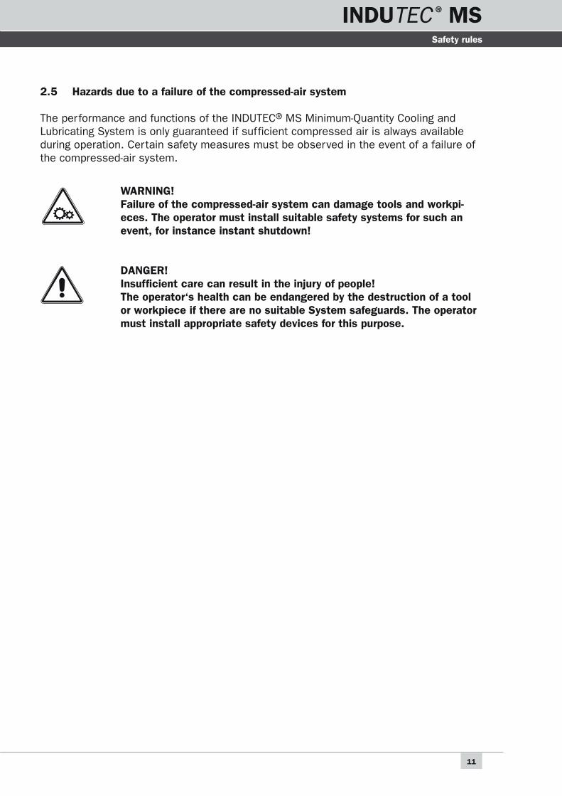
2.5 Hazards due to a failure of the compressed-air system
The performance and functions of the INDUTEC® MS Minimum-Quantity Cooling and Lubricating System is only guaranteed if sufficient compressed air is always available during operation. Certain safety measures must be observed in the event of a failure of the compressed-air system.
WARNING! Failure of the compressed-air system can damage tools and workpi-eces. The operator must install suitable safety systems for such an event, for instance instant shutdown!
DANGER! Insufficient care can result in the injury of people! The operator‘s health can be endangered by the destruction of a tool or workpiece if there are no suitable System safeguards. The operator must install appropriate safety devices for this purpose.

12
INDUTEC ® MS
INDUTEC ® MS
3 Functional principal
INDUTEC® MS spraying heads operate with compressed air. They are triggered by sole-noid valves, pneumatic valves or similiar.
A 3/2-way solenoid valve presses back the spring forced piston into it's operating posi-tion and opens the spraying opening of the spraying head. So the medium is emitted. The adjustment of the material flow rate of the medium is done by throttle valves, the vessel pressure and the stroke of the piston.
When not operating, the 3/2-way solenoid valve bleeds the control air pipe, the needle remains in rest position and closes the medium spraying opening.
Another 3/2-way solenoid valves supplies the spraying air. It discharges through two different holes in the coaxial spraying head and is used for forming and directioning of the air-medium-mixture. The adjustment of the spraying air is done by a throttle valve.
The fog development of the discharging medium depends on the kind of medium, the adjusted amount of medium and the amount of spraying air. These three factors are strongly depending on each other. By choosing optimized parameters a fog-free air-medium-mixture can be reached.
Functional principal

INDUTEC ® MSINDUTEC ® MS
INDUTEC ® MSINDUTEC ® MS
13
Transport and storage
4 Transport and storage
4.1 Transport
The components of the INDUTEC® MS Minimum-Quantity Cooling and Lubricating System are supplied in cardboard boxes. All parts were carefully checked for their fault-less performance before they were packed. The purpose of the packaging is to reliably protect the components from the customary strains and loads arising during transport.
The system has to be transported upright only.
WARNING! The system has to be emptied and cleaned before any transportation. If the system is transported without emptying the correct operation can't be assured.
4.2 Storage
The cardboard boxes must be protected against moisture. They can be stored at temper-atures between 0°C - 80°C. When the cardboard boxes are stacked it is necessary to ensure that the stack does not exert a pressure that could damage the components. The system has to be stored upright only.
14
INDUTEC ® MS
INDUTEC ® MS
5 Installation and setting into operation
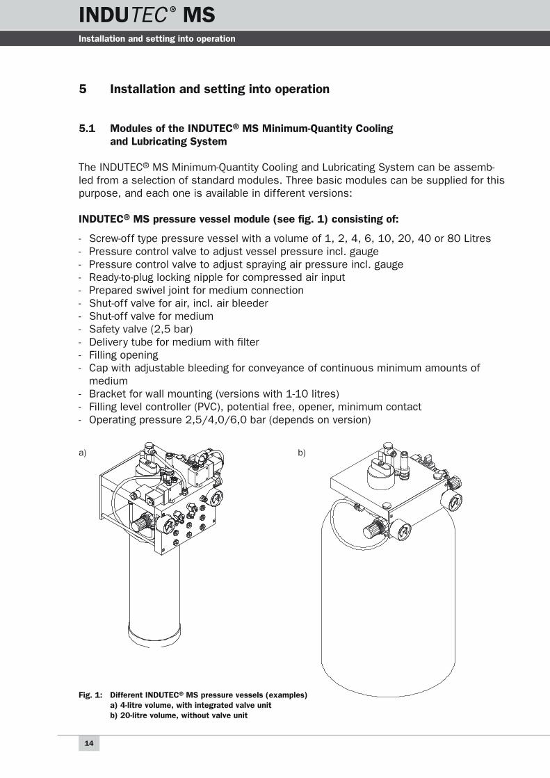
5.1 Modules of the INDUTEC® MS Minimum-Quantity Cooling and Lubricating System
The INDUTEC® MS Minimum-Quantity Cooling and Lubricating System can be assemb-led from a selection of standard modules. Three basic modules can be supplied for this purpose, and each one is available in different versions:
INDUTEC® MS pressure vessel module (see fig. 1) consisting of:
- Screw-off type pressure vessel with a volume of 1, 2, 4, 6, 10, 20, 40 or 80 Litres- Pressure control valve to adjust vessel pressure incl. gauge- Pressure control valve to adjust spraying air pressure incl. gauge- Ready-to-plug locking nipple for compressed air input- Prepared swivel joint for medium connection- Shut-off valve for air, incl. air bleeder- Shut-off valve for medium- Safety valve (2,5 bar)- Delivery tube for medium with filter- Filling opening- Cap with adjustable bleeding for conveyance of continuous minimum amounts of
medium- Bracket for wall mounting (versions with 1-10 litres)- Filling level controller (PVC), potential free, opener, minimum contact- Operating pressure 2,5/4,0/6,0 bar (depends on version)
Fig. 1: Different INDUTEC® MS pressure vessels (examples) a) 4-litre volume, with integrated valve unit b) 20-litre volume, without valve unit
Installation and setting into operation
a) b)

INDUTEC ® MSINDUTEC ® MS
INDUTEC ® MSINDUTEC ® MS
15
Installation and setting into operation
INDUTEC® MS valve unit module (see fig. 2), consisting of:
- Distribution, separately, depending upon the design, for the connection of one to eight coaxial spraying heads
- 3/2-way solenoid valve for control air- 3/2-way solenoid valve for spraying air- Hoses and screw unions to the pressure vessel- Screw-in union for the plug-in connection of the coaxial spraying heads
INDUTEC® MS Valve units are equipped with two different types of solenoid valves, the standard solenoid valves (type S) or special solenoid valves (type A).
18
63 48
68
1
2
3
25
HN-180° umsetzbar
4x90° umsetzbar
G 1/8
40
PG9
22
75 48
73
1
2
3
30
HN-180° umsetzbar
4x90° umsetzbar
G 1/4
50
PG9
Fig. 3: standard solenoid valves (type S) Fig. 4: special solenoid valves (type A)
Fig. 2: Different INDUTEC® MS valve units (examples) a) for a maximum of 2 INDUTEC® MS spraying heads, equipped with 1 INDUTEC® MS spraying head SD4 b) for a maximum of 5 INDUTEC® MS spraying heads, equipped with 3 INDUTEC® MS spraying head SD4 c) for a maximum of 8 INDUTEC® MS spraying heads, equipped with 8 INDUTEC® MS spraying head SD4.
a) b) c)

16
INDUTEC ® MS
INDUTEC ® MS Installation and setting into operation
standard solenoid valves (type S) special solenoid valves (type A)
Design 3/2-way solenoid valve, electrically triggered, with spring
Connection G1/8“ G1/4“
Operating pressure 3 – 10 bar 2,5 – 10 bar
response time at 6 bar on 13 ms, off 16 ms on 15 ms, off 19 ms
Temperature range -10°C – +70°C
Standard current
DC: 12 V, 24 V AC: 24 V, 230 V, 50 – 60 hz
Power consumption
DC: 2,2/4,2 watt AC: 7,0/4,0 watt
Protection class IP 65 acc. VDE 0470 / EN 60529
M2 1
5 3 4
7
9
11 12 13
Z S
8
10
6
M2 1Z S
5
7
13121110
9
8
6
INDUTEC® MS valve units are connected according to the following pneumatic connec-tion scheme:
Fig. 5: Pneumatic connection scheme for INDUTEC®
MS systems with integrated valve unit
Fig. 6: Pneumatic connection scheme for INDUTEC®
MS systems with separate valve unit
1 3/2-way solenoid valve (control air) 8 Visual filling indicator (optional)
2 3/2-way solenoid valve (spraying air) 9 pressure vessel
3 Pressure control valve (spraying air) 10 Filling opening
4 Pressure control gauge (spraying air) 11 Safety valve
5 Pressure control valve (vessel pressure) 12 Shutt-off valve (medium)
6 Pressure control gauge (vessel pressure) 13 Filling level controller
7 Shutt-off valve

INDUTEC ® MSINDUTEC ® MS
INDUTEC ® MSINDUTEC ® MS
17
Installation and setting into operation
INDUTEC® MS coaxial spraying head module (Fig. 7) consisting of:
- Coaxial spraying head- Supply hose, 2 m each, for medium, spraying air and control air- Throttle valves to adjust the medium and the spraying air at the valve unit- Swivel-ring piece for the control air
Fig. 7: INDUTEC® MS SD4 coaxial spraying head
The INDUTEC® MS Minimum-Quantity Cooling and Lubricating System can be expanded in any manner required with a selection of accessory parts. If your System configuration has been expanded by accessories not described in these Operating Instructions, then please observe the corresponding instructions supplied with the accessories. Operation of the System in conformity with the intended purpose (see Ch. 2.2) is not affected by the use of accessories.
5.2 Assembly
Different assemblies of the INDUTEC® MS Minimum-Quantity Cooling and Lubricating System can be produced. Each INDUTEC® MS Minimum-Quantity Cooling and Lubricat-ing System consists of an INDUTEC® MS MS pressure vessel, at least one INDUTEC® MS valve unit, and at least one INDUTEC® MS coaxial spraying head. The System can be expanded by modules and a comprehensive range of accessories.
These Operating Instructions describe the assembly of a standard System in its mini-mum configuration (assembly acc. to fig. 17). More complex Systems involving several modules are assembled according to the same principle as is used to interconnect the standard system. The assembly diagrams in fig. 18 and fig. 19 indicate how the individ-ual valve units have to be interconnected.

18
INDUTEC ® MS
INDUTEC ® MS
5.3 Installing the pressure vessel
5.3.1 Installing the pressure vessel
The pressure vessel (versions from 1 up to 6 litres) is mounted by means of a suspen-sion bracket at the back of the device. The vessel must be firmly secured to a stable and level surface. The vessel must be mounted in such a manner that all operating elements and controls are easily accessible.
The pressure vessel can be mounted directly on the machine where it is to be used for cooling or lubrication, or at a central point within a building to supply a complex system.
180
40 100 40
15
10
660
12
8
Fig. 8: Suspension bracket to mount the vessel (versions with 1 up to 6 litres)
Installation and setting into operation

INDUTEC ® MSINDUTEC ® MS
INDUTEC ® MSINDUTEC ® MS
19
Installation and setting into operation
5.3.2 Installing the filling level controller
Filling level controller/opener (PVC)
Fig. 9: Filling level controller/opener (PVC)
Switching voltage: 230 V
Switching current: 1 A
Braking capacity: 50 watt
Contact type: opener
Protection class: IP 67 (IEC 529)
Temperature range: -10°C … +65°C
The switches have to be grounded with currents extending 48 V.
Fig. 10: Connection scheme for the filling level controller
The filling level controller is available as an optional accessory, and it is used to monitor the filling level in the pressure vessel. The filling level controller generates an electric signal when the filling level in the vessels drops to a minimum value or the cable breaks. This electrical signal can then be used to switch off the machine or System, or to gene-rate a warning signal.
BU BN

20
INDUTEC ® MS
INDUTEC ® MS Installation and setting into operation
The filling level controller is available as an optional accessory, and it is used to monitor two filling levels in the pressure vessel. The first filling level is reached with the spare amount of medium. The second contact is reached with the minimum value. The electri-cal signals can then be used to switch off the machine or System, or to generate a warn-ing signal.
Filling level controller/2 point opener (optional)
Fig. 11: Filling level controller/2 point opener
Fig. 12: Connection scheme for the filling level controller
Switching voltage: 230 V
Switching current: 1 A
Braking capacity: 50 watt
Contact type: 2x opener
Protection class: IP 67 (IEC 529)
Temperature range: -25°C … +75°C
The switches have to be grounded with currents extending 48 V.
BL BK BN

INDUTEC ® MSINDUTEC ® MS
INDUTEC ® MSINDUTEC ® MS
21
Installation and setting into operation
Braking capacity limits
The shown current-voltage-chart refers basically to solenoid proximity switches with integrated reed contactors.
Important: both switching current (A) and switching voltage (W/VA) must not be exeeded in any case.
Overload reasons:
Electrical resistances: light bulbs consumpt about 10–14 times as much current as their nominal value. The switch-on current of a 5 W bulb may be up to 2,5 A at 24 V switching voltage. Capacitors: capacitive loads provide a short-circuit on switching on. Longer control lines work like capacitors as well due to their parallel wires. Starting at 20 m length the result-ing loads may become critical. Electromagnetic coils (contactors, relays, solenoid valves): induce very high voltages on shut-off. In practice loads far over 1,000 V may be reached.
If you’re in doubt about the kind of load your system offers refer to the paragraph about „protecting measures“ or ask for our assistance.
Protecting measures
Specified values for switching current and voltage mustn’t be exceeded even for short times. In case of capacitive or resistive loads (long control lines or relays) we recom-mend the use of a protecting circuit.
Excessive switch-on loads caused by capacities or bulbs may be compensated by use of pre-resistances up to a certain level. These pre-resistances limit the maximum loads of the reed contactor.
Verbotener Bereich
Schaltbereich
V
A0,1 0,2 0,3 0,4 0,5 0,6 0,7 0,8 0,9 1
50
100
150
200
250
Schaltstrom
Sch
alts
pann
ung
Kabelkapazität
R
Last~= R
C
Last~
Dio
de
Last=
+
–
Last~=
Varistor (VDR)
Fig. 13: Capacitive load: pre-resistance Fig. 14: RC element: please ask for our assistance
Fig. 15: Inductive load: recovery diode above load Fig. 16: Varistor (VDR)

22
INDUTEC ® MS
INDUTEC ® MS Installation and setting into operation
DANGER OF DEATH! Involvement with electrical power entails a danger of death! All work on the power supply for the System must be completed by a qualified electrician. The System must first be made currentless before any work on the System can commence. When the INDUTEC® MS Minimum-Quantity Cooling and Lubricating System is integrated into another machine or plant, then in addition to the general safety and accident prevention rules, it is also necessary to observe both the safety instructions for the INDUTEC® Minimum-Quantity Cooling and Lubricating System as well as the safety instructions of the given machine or plant.
5.3.3 Compressed-air connection
The compressed air supplied by the compressed-air network is connected to the existing compressed-air input plug-in nipple via the one-hand connector. The plugin nipple can be exchanged (1/8“ thread size) if a matching connector is not available.
For correct operation a constant input air pressure of min. 6 bar (max. 7 bar) has to be provided. Fluctuations of the input air pressure may cause troubles.
The compressed air must be clean and only very lightly oiled because, otherwise, the oiled compressed air could wet the surface of the sprayed object.
The compressed air must be free of all impurities to guarantee faultless operation of the coaxial heads.
WARNING! Polluted compressed air can disrupt the faultess operation of the System. This, in turn, can increase the amount of necessary mainte-nance work or even damage the tool or workpiece.

INDUTEC ® MSINDUTEC ® MS
INDUTEC ® MSINDUTEC ® MS
23
Installation and setting into operation
5.4 Installing the valve unit
The standard system has a valve unit which is directly mounted on the pressure vessel (see fig. 17).
If the System features one or more separate valve units (see fig. 18 and fig. 19), then these have to be connected to the pressure vessel with the supplied pressure hoses.
WARNING! Incorrect connection of the hoses can destroy the System!
Fig. 17: Connecting diagram for the INDUTEC® MS standard system consisting of a pressure vessel of 2-litre capacity with integrated valve unit, and an INDUTEC® MS coaxial spraying head SD4.
24
INDUTEC ® MS
INDUTEC ® MS
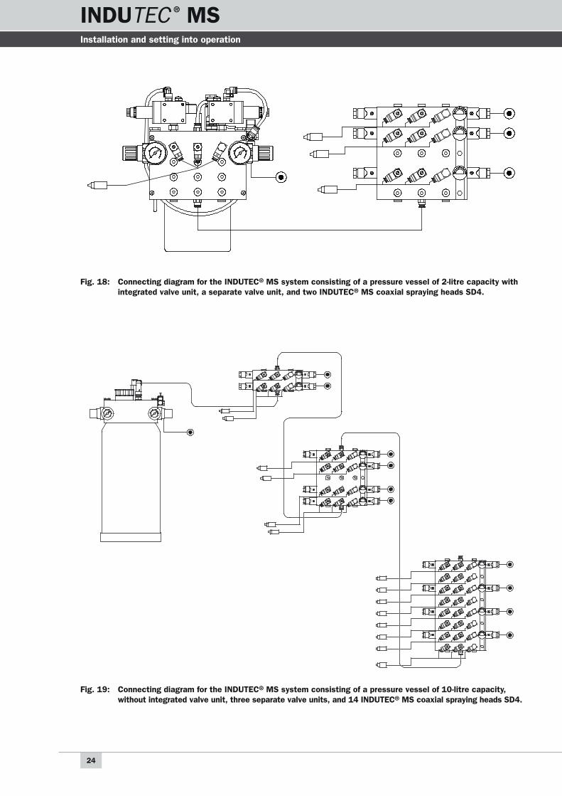
Fig. 18: Connecting diagram for the INDUTEC® MS system consisting of a pressure vessel of 2-litre capacity with integrated valve unit, a separate valve unit, and two INDUTEC® MS coaxial spraying heads SD4.
Fig. 19: Connecting diagram for the INDUTEC® MS system consisting of a pressure vessel of 10-litre capacity, without integrated valve unit, three separate valve units, and 14 INDUTEC® MS coaxial spraying heads SD4.
Installation and setting into operation
INDUTEC ® MSINDUTEC ® MS
INDUTEC ® MSINDUTEC ® MS
25
Installation and setting into operation
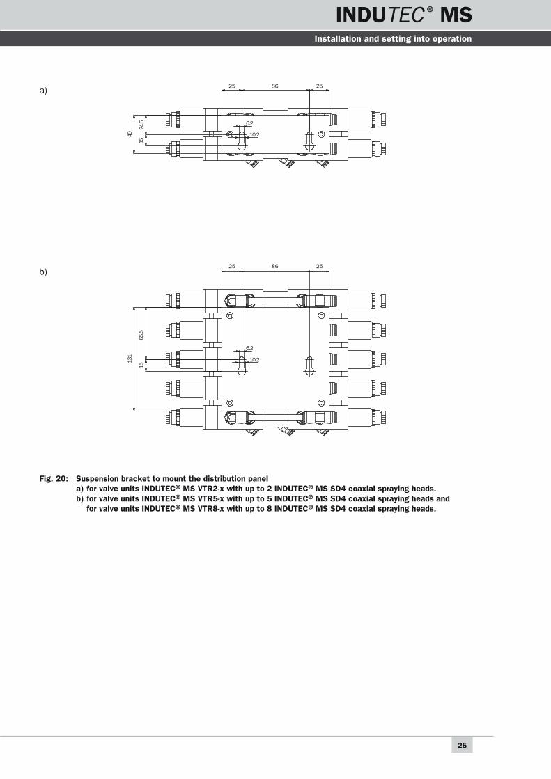
Fig. 20: Suspension bracket to mount the distribution panel a) for valve units INDUTEC® MS VTR2-x with up to 2 INDUTEC® MS SD4 coaxial spraying heads.
b) for valve units INDUTEC® MS VTR5-x with up to 5 INDUTEC® MS SD4 coaxial spraying heads and for valve units INDUTEC® MS VTR8-x with up to 8 INDUTEC® MS SD4 coaxial spraying heads.
25 86 25
6.2
10.2
25 86 25
6.2
10.265
.5
131
15
49
24.5
15
a)
b)

26
INDUTEC ® MS
INDUTEC ® MS
5.4.1 Electrical connection
After the pressure vessel has been linked to the compressed-air system, the solenoid valves must be supplied with power, either 24 V/DC or 230 V/AC, depending upon the type of solenoid valve concerned. The electrical system can be connected to the power supply system of the machine/plant in which the System is integrated. The solenoids of the valves can be exchanged. Standard solenoids are available for connection to 24 V/DC or 230 V/AC. Please contact the manufacturer for other special voltages.
The solenoid valves are closed when no current is supplied to the solenoids. The sole-noids must be connected in such a manner that they are supplied with power for the duration of the required spraying time. The solenoid valve for spraying air and control air should be parallel circuited.
Depending upon the intended application, the valves can or must be controlled by suita-ble circuits in such a manner that the spraying head always remains clean and prevents the formation of drops. For this purpose the cycle time for the solenoid valve for spraying air (3) must be selected in such a manner that it closes a few tenths of a second after the solenoid valve for control air (14) (see functional principle in Ch. 3). This ensures that the spraying head remains open for this period so that any remaining medium is sprayed. The cycle time is reversed when the head is switched on so that the signal for spraying air is a few tenths of a second earlier than for the signal for the control air.
DANGER OF DEATH! Involvement with electrical power entails a danger of death! All work on the power supply for the System must be completed by a qualified electrician. The System must first be made currentless before any work on the System can commence. When the INDUTEC® MS Minimum-Quantity Cooling and Lubricating System is integrated into another machine or plant, then in addition to the general safety and accident prevention rules, it is also necessary to observe both the safety instructions for the INDUTEC® MS Minimum-Quantity Cooling and Lubricating System as well as the safety instructions of the given machine or plant.
Installation and setting into operation
INDUTEC ® MSINDUTEC ® MS
INDUTEC ® MSINDUTEC ® MS
27
Installation and setting into operation
5.5 Installing the coaxial spraying heads
The coaxial spraying heads must first be installed at the required points in the machine or plant. Ensure that the spraying heads are firmly secured and correctly located. Direct the spraying heads in such a manner that the sprayed medium optimally covers the tool or workpiece at the required point.
DANGER! Insufficient care can result in the injury of people! Ensure that the statutory safety machines for the machine or plant in which the spraying heads are installed are fulfilled. Never reach into the area of moving parts of the machine or plant. The spraying heads must not be installed in the danger area of rotating or moving tools.
DANGER! Insufficient care can result in the injury of people! Never direct the sprayed jet at people. The medium itself, as well as the actual spraying pressure, can seriously harm health!

28
INDUTEC ® MS
INDUTEC ® MS
The INDUTEC® MS coaxial spraying head SD4 can be installed in any position. The distance to the coating surface depends upon the required coating width. The piston case incor-porates an M5 internal thread by which the spraying head can be securely installed. The INDUTEC® MS clamping holder KH 5 is avail-able as an optional attachment for this spray-ing head.
Intermittent operation of the INDUTEC® MS coaxial spraying head SD 5 generates natural vibrations. Consequently, it is essential to ensure that the spraying head is securely and safely installed. The transmission of vibra-tions from the machine to the spraying head must be avoided.
DANGER! Insufficient care can result in the injury of people! Ensure that the spraying head is securely seated. Incorrect installa-tion means that the spraying head can become loose during operation, thereby damaging the system, the tool or the workpiece.
Installation and setting into operation
3.5
34.8
39.8
ø13
(5) 23.5
28.5
SW 11
0 0.0
5-
M5–4deep
Fig. 22: Dimensions of the INDUTEC® MS SD4 coaxial spraying head
Fig. 21: INDUTEC® MS SD4 coaxial spraying head
The standard version of the INDUTEC® MS coaxial spraying head SD4 supplies an air-enveloped round jet at a spraying angle of 5°. Various accessory attachment caps can be used to produce different jet shapes and spraying angles.
5.5.1 Installing the INDUTEC® MS coaxial spraying head of the SD4 series
INDUTEC ® MSINDUTEC ® MS
INDUTEC ® MSINDUTEC ® MS
29
Installation and setting into operation
Black (S = control air)Blue (Z = spraying air)
Transparent (M = medium)
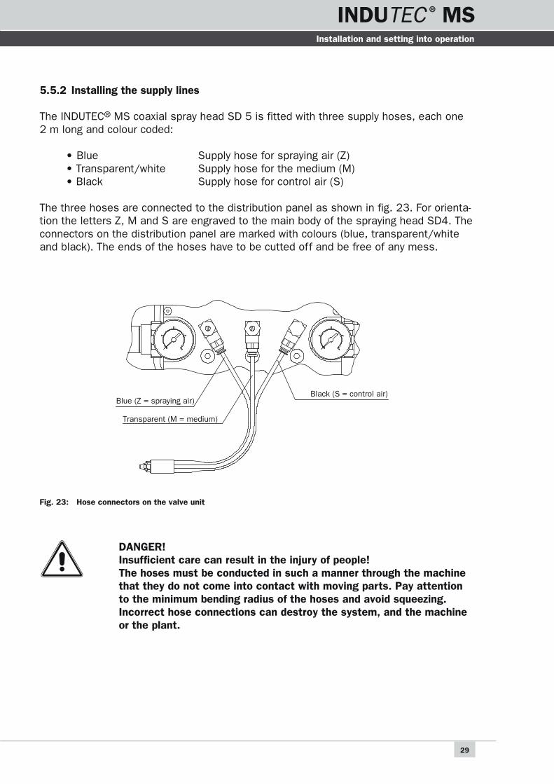
Fig. 23: Hose connectors on the valve unit
DANGER! Insufficient care can result in the injury of people! The hoses must be conducted in such a manner through the machine that they do not come into contact with moving parts. Pay attention to the minimum bending radius of the hoses and avoid squeezing. Incorrect hose connections can destroy the system, and the machine or the plant.
5.5.2 Installing the supply lines
The INDUTEC® MS coaxial spray head SD 5 is fitted with three supply hoses, each one 2 m long and colour coded:
• Blue Supply hose for spraying air (Z) • Transparent/white Supply hose for the medium (M) • Black Supply hose for control air (S)
The three hoses are connected to the distribution panel as shown in fig. 23. For orienta-tion the letters Z, M and S are engraved to the main body of the spraying head SD4. The connectors on the distribution panel are marked with colours (blue, transparent/white and black). The ends of the hoses have to be cutted off and be free of any mess.

30
INDUTEC ® MS
INDUTEC ® MS
5.6 Starting up the System
5.6.1 Filling the pressure vessel
The pressure vessel must only be filled with suitable media. Special safety measures must be observed, depending upon the type of medium. Aggressive substances such as acids, lyes, cleaning agents, chemicals, etc., must not be sprayed. Contact the manu-facturer of the medium if you are not certain whether the given medium is suitable for the INDUTEC® MS Minimum-Quantity Cooling and Lubricating System. All media must be processed in a clean and filtered state.
DANGER! Insufficient care can result in the injury of people! Danger as a result of media that are flammable and a health hazard! The safety instructions on the spraying containers or the safety data sheet must be observed.
The sprayability of a medium depends primarily upon its viscosity and composition. Conduct practical tests to obtain the necessary results. The coaxial spraying heads must be regularly cleaned if sticky or resinous media are used, or if they have a tendency to dry up.
NOTE! Only use soft brushes and a neutral cleaner for cleaning. Do not use metal or sharp-edged tools!
WARNING! The seals in the coaxial spraying heads are made of Viton. These seals can be destroyed by aggressive cleaners.
Installation and setting into operation
INDUTEC ® MSINDUTEC ® MS
INDUTEC ® MSINDUTEC ® MS
31
Installation and setting into operation
The pressure vessel must only be filled with the media through the filling opening [1] provided for this purpose. Please observe the following procedure:
1. First close the shut-off valve for the medium [12] (see fig. 24).
2. Then vent the pressure vessel by closing the shut-off valve for the compressed air [16].
3. Unscrew the filling opening for the medium [1].
4. Pour in the medium, ensuring that the maximum permissible filling level is observed. The maximum permissible filling level is indicated by the end of the cylindric part of the pressure vessel.
WARNING! Medium can enter the comprompressed-air supply network of the solenoid valves and damage these when an excessively filled vessel is vented.
WARNING! The medium must be free of any mess and contamination. Otherwise the system might be damaged.
WARNING! Check the filling level of the pressure vessel regularly. Air will enter the System if the filling level drops below the level of the rising tube [20]. This can result in a failure of the coaxial spraying heads, thereby damaging the system, tool or workpiece.
DANGER! Insufficient care can result in the injury of people! Ensure that the pressure vessel is made pressureless (see points 1. and 2.) before opening the filling point for the medium.

32
INDUTEC ® MS
INDUTEC ® MS
Fig. 24: Examples of shut-off valve settings: Shut-off valve for medium [12] closed. Shut-off valve for compressed air [16] closed.
5.6.2 Setting the System into operation
The following conditions must be fulfilled before the System is set into operation:
• The System must be connected to the compressed-air network in conformity with these Operating Instructions (maximum input air pressure = 6 bar).
• The System must be connected to the power supply in conformity with these Operating Instructions.
• The pressure vessel must be filled with a permissible medium in conformity with these Operating Instructions.
DANGER! Insufficient care can result in the injury of people! The spraying process can be accompanied by a loud noise, depend-ing upon the spraying air and the conveying pressure for the medium. Consequently, all persons working in the immediate vicinity should therefore wear appropriate goggles and ear defenders to avoid damage to the health.
Installation and setting into operation
12
1
16

INDUTEC ® MSINDUTEC ® MS
INDUTEC ® MSINDUTEC ® MS
33
Installation and setting into operation
1. First open the shut-off valve for the input air [16] on the pressure vessel, and throt-tle the spraying air to a pressure of 6 bar with the help of the pressure control valve for spraying air [17]. The pressure of the spraying air is indicated by the pressure gauge for input pressure [18].
DANGER! Insufficient care can result in the injury of people! The input air pressure mustn't exeed 6 bar.
2. Adjust a pressure of approx. 0.5 bar with the control valve for vessel pressure [4] and open the shut-off valve for the medium [12]. The pressure inside the vessel is indicated by the pressure gauge for vessel pressure [5]. It is essential to ensure that the maximum vessel pressure of 2.5 bar is not exceeded!
3. Open the forced exhaust slowly [1].
NOTE! Should high medium pressures be necessary it is then imperative that the corresponding accident prevention rules of the professional asso-ciations are observed.
4. Screw in the throttle valve for spraying air [7] completely by turning it clockwise.
5. Screw out the throttle valve for medium [8] by turning it anti-clockwise.
6. Check, and if necessary correct, the seat of the coaxial spraying heads.
7. Actuate the solenoid valves to fill the entire medium hose system with medium. After approx. 10 to 12 seconds a fine jet of medium is emitted by the coaxial spray-ing heads. It is important to ensure that all medium-conducting lines are free from trapped air. Consequently, allow all connected coaxial spraying heads to run for 10 to 20 seconds in an uncycled condition.
WARNING! Medium flow with the control screw must only be regulated when the control air has positioned the needle to its open setting. The coaxial spraying head can be destroyed if this is not the case.
34
INDUTEC ® MS
INDUTEC ® MS Installation and setting into operation
8. Complete the fine settings only if it is certain that the entire System is free of air. For this purpose turn the throttle valve for the medium [8] to zero (but screwing in the control screw) until drops of medium are emitted by the coaxial spraying head.
9. Open the throttle valve for spraying air [7] (by unscrewing the control screw) and adjust the required spraying volume.
WARNING! The medium flow must only be restricted (by turning the control screw clockwise) while medium is still flowing out of the spraying head. After the spraying head has been closed, do NOT continue turning the cont-rol valve clockwise!
10. Adjust the spraying cycle and check the spraying pattern once again. Correct the setting should this prove to be necessary.
NOTE! For brief standstills the medium can remain under pressure in the spraying head (no connection with the outside air). However, for prolonged standstills the medium supply should be made pressureless.

INDUTEC ® MSINDUTEC ® MS
INDUTEC ® MSINDUTEC ® MS
35
Maintenance and repair
6 Maintenance and repair
The INDUTEC® MS coaxial spraying heads are high quality precision devices which, when properly treated, are not prone to disruption and can be operated almost free of any maintenance. However, it must be assumed that the medium is always applied in a clean and filtered condition. The control air supplied to the INDUTEC® MS coaxial spraying head must also be clean and only very lightly oiled should this be necessary. Individual operating conditions and differing coating media, however, do require a minimum of equipment care.
DANGER! Insufficient care can result in the injury of people! Prior to all repairs and maintenance work it is imperative to ensure that all supply lines are made pressureless and then disconnected from the pressure controllers or the medium pressure vessel!
6.1 Cleaning
Do not use metal, sharp-edged tools but rather only soft brushes for external cleaning of INDUTEC® MS coaxial spraying heads.
Equipment that has become dirty as a result of use must be thoroughly rinsed. This is particularly the case when the needle, O-ring or INDUTEC® coaxial spraying head have to be changed.
NOTE! Only use soft brushes and a neutral cleaner for cleaning. Do not use metal or sharp-edged tools!
WARNING! The seals in the coaxial spraying heads are made of Viton. These seals can be destroyed by aggressive cleaners.

36
INDUTEC ® MS
INDUTEC ® MS Maintenance and repair
1. All connections must be made pressureless.
2. Release union ring [fig. 25, SD-3] with an SW 11 open-end spanner.
3. Disassemble the parts of the spraying head according to fig. 25.
4. Clean all parts.
5. Renew O-rings if necessary.
6. Reverse the sequence to assemble with replaced or carefully cleaned parts. The O-rings should be lightly greased.
DANGER! Insufficient care can result in the injury of people! Prior to all repairs and maintenance work all supply lines must be made pressureless and disconnected from the pressure controllers or the medium pressure vessel.
NOTE! Never use sharp-edged or metallic objects to remove or return seals. Both the seals and their seats can be damaged when they are exchanged.
NOTE! When INDUTEC® MS coaxial spraying heads and INDUTEC® MS coaxial spraying head needles that have been in use are returned, the spray-ing head must be thoroughly rinsed with a corresponding solvent so that no medium residues are left in the spray head. The needle shaft must be freed of all residue particles. Needles with encrusted medium residues will damage the new sealing element. Even the course of a needle that is not perfectly clean through the O-ring can result in leaks.

INDUTEC ® MSINDUTEC ® MS
INDUTEC ® MSINDUTEC ® MS
37
Maintenance and repair
Pos. Description
1.0.3 In-head cartridge 0,3 mm dia
2 Air cap
3 Union ring
4 Sealing screw
5 O-Ring 5x1, Viton
6 O-Ring 10x1, Viton
7 Quadring 2x1,5, Viton
8 Needle with piston
10 Main body
13 Spring
13.1 Spring backing run
24 Stroke adjustment screw, short
Fig. 25: Parts of the INDUTEC® MS coaxial spraying head SD4
2
6
3
7
5
4
5
1.0.3
8
5
13
13.1
10
24
6.2 Trouble-shooting
6.2.1 No medium is emitted from the spraying head
1. Check whether there is enough medium in the vessel.
2. Check whether the shutt-off valve for medium [12] is opened.
3. Check whether the pressure of the control air is sufficient (6 bar).
4. Check whether the solenoid valves are operating properly.
5. Check whether the hoses are laid properly.
6. Check whether the stroke adjustment screw is in neutral position.
7. Check whether the control air pulse is long enough.
8. Check whether the needle with piston [fig. 25, pos. 8] can be moved easily.
9. Check whether in-head cartridge [fig. 25, pos. 1.0.3] is free of any mess.
You'll find a list of all parts of the INDUTEC® MS coaxial
spraying head SD4, especially of the part numbers of the
different cartridges, inside the operating manual of the
INDUTEC® MS coaxial spraying head SD4 or visit our website
at www.menzel-metallchemie.de.

38
INDUTEC ® MS
INDUTEC ® MS
6.2.2 Air bubbles are rising in the medium hose
1. With unfavourable conditions like very small amounts of medium and relatively high vessel pressure building up of air bubbles in medium hose may occur. Increase the material flow rate at the throttle valve for medium and decrease the vessel pressure.
2. Check whether the O-ring [fig. 25, pos. 5] is defective.
3. Check whether there is enough medium in the vessel.
4. Check whether the vessel is positioned free of any vibrations.
6.2.3 Intense mist formation
The used medium, the amounts of spraying air and medium affect the amount of mist formation strongly. By decreasing the material flow rate of the medium and concurrent increasment of the spraying air the medium can be directioned much better.
6.2.4 Coaxial spraying head continues to drip
1. Check whether mess or contamination are plugging the in-head cartridge [fig. 25, pos. 1.0.3].
2. Check whether the needle with piston [fig. 25, pos. 8] can be moved easily.
3. Check whether the control air line is squeezed -> control air can't exhaust via the solenoid valve.
6.2.5 On ore more coaxial spraying heads are ebbing after a certain amount of time
1. Check whether the forced exhaust at the filling opening for the medium [1] is open.
2. The ratio between medium and vessel pressure is unfavourable. Normally this happens with small amounts of medium and relatively high vessel pressure. Increase the material flow rate at the throttle valve for medium and decrease the vessel pressure.
Maintenance and repair
INDUTEC ® MSINDUTEC ® MS
INDUTEC ® MSINDUTEC ® MS
39
Shutting down
7 Shutting down
Observe the following points when shutting down the INDUTEC® MS Minimum-Quantity Cooling and Lubricating System:
Ensure that all parts of the System are pressureless before the lines are dismantled.
Medium residues, depending upon the kind of medium used, must be properly disposed off. Commission specialists with the disposal of residue medium if the company does not have its own service for this purpose.
DANGER! Insufficient care can result in the injury of people! Danger as a result of media that are flammable and are a health hazard! The safety instructions on the spraying containers or the safety data sheet must be observed.
Clean all parts of the system with suitable cleaners so that they can be used again.
NOTE! Only use soft brushes and a neutral cleaner for cleaning. Do not use metal or sharp-edged tools!
WARNING! The seals in the coaxial spraying heads are made of Viton. These seals can be destroyed by aggressive cleaners.

40
INDUTEC ® MS
INDUTEC ® MS
8 Technical data
8.1 Dimensions
Fig. 26: Principal dimensions of the INDUTEC® MS standard system with pressure vessel 1-litre capacity, with valve unit for up to 4 INDUTEC® MS coaxial spraying heads SD4.
Technical data
280
240
32
0
280
240
32
5
280
240
54
0
280
240
54
0
280
240
69
0
The correct dimensions of all other systems can be found in our main catalogue and on our website at www.menzel-metallchemie.de.
Fig. 27: Principal dimensions of the INDUTEC® MS standard system with pressure
vessel 2-litre capacity, with valve unit for up to 4 INDUTEC® MS coaxial
spraying heads SD4.
Fig. 28: Principal dimensions of the INDUTEC® MS standard system with pressure
vessel 4-litre capacity, with valve unit for up to 4 INDUTEC® MS coaxial
spraying heads SD4.
Fig. 29: Principal dimensions of the INDUTEC® MS standard system with pressure
vessel 6-litre capacity, with valve unit for up to 4 INDUTEC® MS coaxial
spraying heads SD4.
Fig. 30: Principal dimensions of the INDUTEC® MS standard system with pressure
vessel 10-litre capacity, with valve unit for up to 4 INDUTEC® MS coaxial
spraying heads SD4.

INDUTEC ® MSINDUTEC ® MS
INDUTEC ® MSINDUTEC ® MS
41
Technical data
8.2 Sealing materials
Basically all seals contacting the medium consist of fluorine caoutchouc FPM (Trading name Viton).
Basic elastomer Application area / specifics
Fluorine caoutchouc Viton Mineral oils and fats, aliphatic, aromatic and Viton chlorinated hydrocarbons, gasoline,
premium gasoline, diesel, flame-proof phosphate-esterbased fluids, acids, alkalis,
silicone oils and fats. high vaccuum applicable!
Usage of other media
For the usage of other media with the INDUTEC® MS Minimum-Quantity Cooling and Lubricating System a lot of sealing materials can be used instead of Viton. There are appropriate sealing materials for almost any kind of medium.
Basic elastomer Application area / specifics
Ethylene propylene
diene-caoutchouc
EPDM
Peroxide cross linked, hot water, steam, brake fluids, detergents, alcohol, cetones,
circulating water, flame-proof phosphate acid-ester-based fluids, organic and inorganic
acids and bases. No mineral oil-stability.
Acrylonitrile butadiene
caoutchouc
NBR
Basic material for hydraulics and pneumatics. Mineral oil based hydrostatics, animal
and vegetable oils and fats, flame-proof fluids (HFA, HFB, HFC), aliphatic hydrocarbons
(propane, butane, gasoline), silicone oils and fats, water up to +80°C, bio oils made up
from synthetic esters.
chlorine butadiene
caoutchouc
CR
Cooling agent-resistant, ammonia, carbon dioxide, freons (R12, R13, R21, R22, R113,
R114, R115), silicone oils, water, oxygen (low-pressure), bleaching agents, caustic
soda solution, alcohol, chlorine, ozone, castor based and other vegetable oils. Low
mineral oil-stability.
ISOLAST®
perfluoric elastomer
Offers the widest range of stability to chemicals. Therefore it’s applicable for almost
any task within chemical process technology between -25°C and +240°C. It offers
an excellent resistance to almost all organic and inorganic acids, cetones, esters,
solvents, amines, hot water, steam as wells as ethylene oxid and propylene oxid.
Silikone caoutchouc
MVQ
Hot air, oxygen, inactive gases at high temperatures, ozone, uv-radiation, aliphatic
motor and transmission oils, animal and vegetable oils and fats, brake liquids. Low
mineral oil-stability. For static use only.
Tetra fluorine ethylene
propylene caoutchouc
TFE/P
Mineral oils and fats, brake liquids, fuels, alcohols, thermal transmitters, oils, amines,
acids, bases.
Hydrated acrylonitrile
butadiene caoutchouc
HNBR
Mineral oils and fats. Applicable for high dynamic loads, abrasion-proof, high tensile
and chink strenght, extrusionresistant.
High capacity elastomer
ZalacTM/FFPM
High capacity elastomer for a wide range of temperatures. Ideal for fuels, paints and
enamels, chemical media.

42
INDUTEC ® MS
INDUTEC ® MS
9 Manufacturer‘s declaration
Manufacturer‘s declaration
In keeping with EC Guideline Machines 89/392/EEC, Annex II B for Machines that are to be built-in
Machine design
Make: INDUTEC® Minimal-Mengen-Kühl-Schmier-System
Type designation: INDUTEC® MS
has been developed, designed and manufactured in conformity with the EC Guideline 89/392/EEC
under the sole responsibility of
Menzel Metallchemie GmbH
Im Gewerbepark 14
D-73329 Kuchen
GERMANY
The following harmonising standards have been applied:
- DIN EN 292 – Safety of Machines, Equipment and Plants
- DIN EN 60 204.1 – Electrical Equipment for Industrial Machines
A complete technical documentation exists.
The machine is backed by corresponding operating instructions:
- In the original version
- In the national language of the user (English)
Operation of this machine is prohibited until it has been established that the machine in which it is
to be integrated conforms with the regulations of the EC Guidelines for Machines, the hormonising
standards/European standards or the corresponding national standards!
Kuchen, dated 01.01.1997 ........................................
Signature of manufacturer
Manufacturer‘s declaration

INDUTEC ® MSINDUTEC ® MS
INDUTEC ® MSINDUTEC ® MS Hersteller-Erklärung

Im Gewerbepark 14D - 73329 Kuchen
Postfach 1166D - 73327 Kuchen
Phone +49 (0) 73 31 - 9 87 80Fax +49 (0) 73 31 - 8 29 46Internet www.menzel-metallchemie.dee-Mail [email protected]
MENZEL METALLCHEMIE
is the pioneer in developing
biodegradable high perform-
ance oils. Due to long lasting
and consequent optimization
of employment we deliver a
comprehensive solution not only
for challenging tasks in cutting
and non-cutting machining but
also for wood, glass, plastic or
other industry purposes.
environmentally sound, cost-
effective and process-safe.
Modular, flexible and competitive.
Together with You we develop
the optimized solution for Your
individual tasks.
Talk to us.
com
.uni
ts G
mbH
Stu
ttga
rtApplication examples from metal machining
INDUTEC ® MSMinimum-Quantity Cooling and Lubricating System