MINIFp'R FORTRAN PROGRAMMING THROUGH SIMULATION...
134
MINIFOR: minicomputer real-time FORTRAN programming through simulation Item Type text; Thesis-Reproduction (electronic) Authors Upchurch, James Kimble, 1943- Publisher The University of Arizona. Rights Copyright © is held by the author. Digital access to this material is made possible by the University Libraries, University of Arizona. Further transmission, reproduction or presentation (such as public display or performance) of protected items is prohibited except with permission of the author. Download date 24/06/2018 23:29:22 Link to Item http://hdl.handle.net/10150/554942
Transcript of MINIFp'R FORTRAN PROGRAMMING THROUGH SIMULATION...

MINIFOR: minicomputer real-timeFORTRAN programming through simulation
Item Type text; Thesis-Reproduction (electronic)
Authors Upchurch, James Kimble, 1943-
Publisher The University of Arizona.
Rights Copyright © is held by the author. Digital access to this materialis made possible by the University Libraries, University of Arizona.Further transmission, reproduction or presentation (such aspublic display or performance) of protected items is prohibitedexcept with permission of the author.
Download date 24/06/2018 23:29:22
Link to Item http://hdl.handle.net/10150/554942
MINIFp'R
MINICOMPUTER REAL-TIME
FORTRAN PROGRAMMING THROUGH SIMULATION
byJames Kimble Upchurch
A Thesis Submitted to the Faculty of the
COMMITTEE ON. COMPUTER SCIENCE
In Partial Fulfillment of the Requirements For the Degree of
MASTER OF SCIENCE
In the Graduate College
THE UNIVERSITY OF ARIZONA
1 9 7 2

STATEMENT BY AUTHOR
This thesis has been submitted in partial fulfillment of requirements for an advanced degree at The University of Arizona and is deposited in the University Library to be made available to borrowersunder rules of the Library,
Brief quotations from this thesis are allowable without special, permission, provided that accurate acknowledgment of source is made. Requests for permission for extended quotation from or reproduction of this manuscript in whole or in part may be granted by the head of the major department or the Dean of the Graduate College when in his judgment the proposed use of the material is in the interests of scholarship. In all other instances, however, permission must be obtained from the author.
SIGNED:
APPROVAL BY THESIS DIRECTOR
This thesis has been approved on the date shown below:
Assbqiate Professor of Chemical Engineering
ACKNOWLEDGMENT
The author is sincerely grateful to Professor James Wm. White
for suggestion of the topic and guidance during its development. Many
thanks are extended to Professor John V. Wait for his discussion and
helpful suggestions. The author is also very grateful to the United
States Air Force for allowing him to pursue the degree culminating in
this thesis .while on active duty.
TABLE OF CONTENTS- ■ .* •
Page
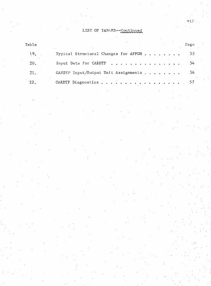
LIST OF T A B L E S ................ ..... ........... . . . . ... . vi
LIST OF ILLUSTRATIONS . . . . . . . viil
ABSTRACT . .......... . . . . . . . . . . . x
CHAPTER
1 INTRODUCTION «, . . . . . . . . . 1
Motivation e . e . ............... . » • « » 1An Alternative a . 3Processing Performed . . • .. . , e » . . . » e , 5Restrictions and Limitations , « ..... ....... 7
2 HOW TO USE MINIF^R . . ........ . .... ....... 11
■ Specifying the Program Input a . . . . . . 0. * . 11FORTRAN Subroutines . . » . e.... ....... 12Input Data . . . . 20
Specifying the Processing Desired » , » » . = <, 29Executive Interfaces „ . » e « e . . „ . . . 30Process Input/Output Interfaces 30
Submitting a Processing Request . . . . . . . . 43Processing at The University of Arizona . . 43Processing at Other Installations . . . . . 45
Error Correction and Resubmission . . . . . . . 46Errors in the Input Data ... . . . . . . . . 46Abnormal Termination . . . . . . . . . * . . 46
Requesting Punched Paper Tape SourcePrograms . . . . . . . . . . . . . . . . . . . 52Organizing the Data and Submitting
a Request . . . . . . . . . . . „ . . . . 53CARDTP Diagnostics . . . ......... 56
3 SPECIFIC APPLICATIONS . . . . . . . . . . . . . . . 58
Data Acquisition . . . « . . . . . . . . . . . .. 58Process Control . . . . . . . . . . . . . . . . 63
iv
TABLE OF CONTENTS— Continued
Page
4 SUMMARY AND SUGGESTED FUTURE DEVELOPMENT . . . . . . 99
APPENDIX A: GLOSSARY OF TERMS . . . . . . . . . . . . . . . . . 102
APPENDIX B: MINIF0R. CODING FORMS . . . . . .......... 104
APPENDIX C: INTEGRATION ROUTINES . . . . . . . .......... ". . 118
REFERENCES . . . . . . . . '. _. . . . . . . . ............. 121

LIST OF TABLES
Table Page
1, Program Dimension Limitations . . . . . . . . . . . 10:
20 Program Components of MINIF^R 13
3. Rules for Constructing SUBROUTINE MODEL . . . . . . 15
4. MINIF0R Dead Time Functions . . . . . . . . . . -..o' . 16
5. Data for Stirred-Tank Reactor . ......... . . . 19
6. Instructions for Coding Card 2 . . . . . . . . . . . 23
7. Instructions for Coding Card 3 . . .............. 24
8. Delaying Continuation of a Program,SUBROUTINE WAIT(l,K,M) . . . . . . . . . . . . . . . 31
9. Analog Inputs in a Sequential Order,SUBROUTINE A I S Q W ( I , . . .......... 33
10. Analog Inputs in a Random Order,SUBROUTINE AIRDW(l,J,K,M) . . 34
11. Digital Inputs, SUBROUTINE DIW(l,J,K,M) . . . . . . 35
12. Analog Outputs, SUBROUTINE A0W(I,J,K,M) . . . . . . 36
13. Latching Digital Outputs, SUBROUTINEDOLW(l,j,Kl,K2,M).......... . . . . 37
14. Momentary Digital Outputs, SUBROUTINED0MM(I,J,K,N,M)......... . . . ........... . 38
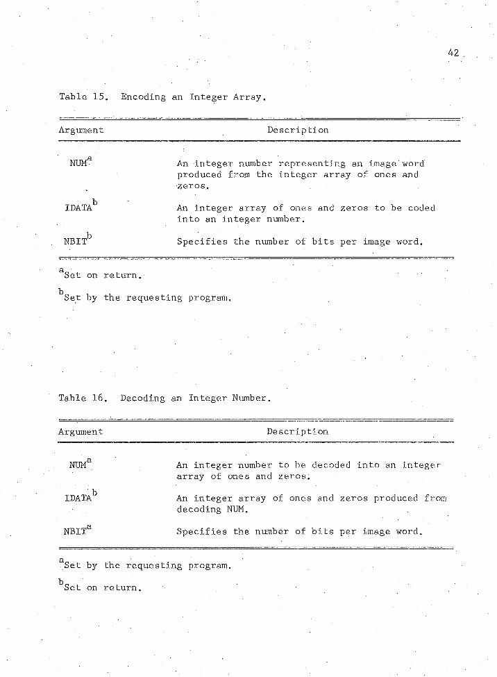
15. Encoding an Integer Array . . . . . . . . . . . . . 42
16. Decoding an Integer Number .............. 42
17. MINIF0R Input/Output Unit Assignments.......... . 45
18. • -MINIF0R Diagnostics and Fatal Errors . . . . . . . . 47
. . vi . „ '
vii
LIST OF TABLES— Continued
Table Page
19. Typical Structural Changes for APPGM . . . . . . . . 53
20. Input Data for C A R D T P . 54
21. CARDTP Input/Output Unit Assignments . . , . . « . . 54
22. CARDTP Diagnostics . . . . . . . . . . . . . . . . . 57
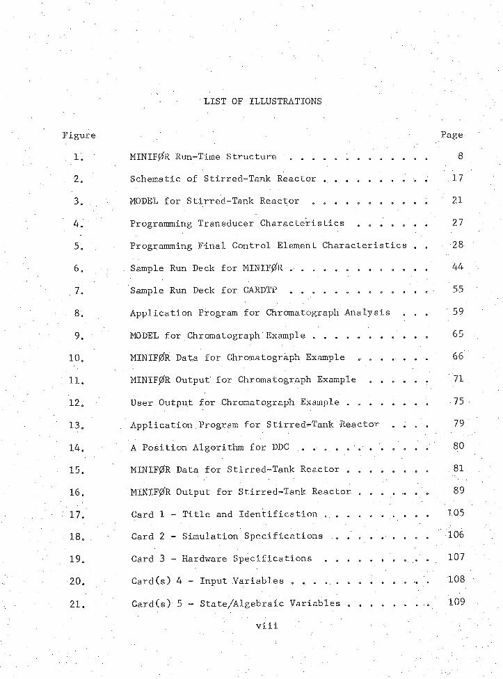
LIST OF ILLUSTRATIONS
Figure Page
1. MINIF0R Run-Time Structure . . . . . . . . . . . . 8
2. Schematic of Stirred-Tank Reactor . . . . . . . . . .. 17
3. MODEL for Stirred-Tank Reactor . . . . . . . . . . . 21
4. Programming Transducer Characteristics . . . . . . . 27
5. Programming Final Control Element Characteristics . . 28
6. Sample Run Deck for MINIF0R . . . . . . . . . . . . . 44
7. Sample Run Deck for CARDTP . . . . . . . . . . . . . 55
8. Application Program for Chromatograph Analysis . . . 59
9. MODEL for Chromatograph Example . . . . . . . . . . . 65
10. MINIF0R Data for Chromatograph Example . . .. . . . . 66
11. MINIF0R Output’ for Chromatograph Example . . . . . . 71
12. User Output for Chromatograph Example . . . . . . . . 75
13j Application Program for Stirred-Tank Reactor . . . . 79
14. A Position Algorithm for DDC .. . . . . . . . . . . . 80
15. MINIF0R Data for Stirred-Tank Reactor . . . . . . . . 81
16. MINIF0R Output for Stirred-Tank Reactor. . . . . .. . . 89
17. Card 1 - Title and Identification . . . . . . . . . . 105
18. Card 2 - Simulation Specifications . . . . . . . . . 106
19. Card 3 - Hardware Specifications . . . . . . . . . . 107
20. Card(s) 4 - Input Variables . . . . . . . . . . . . 108
21. Card(s) 5 - State/Algebraic Variables . . . . . . . . 109
' - viii .
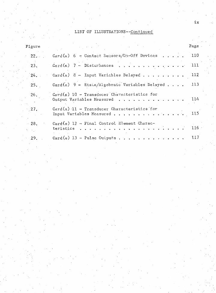
LIST OF ILLUSTRATIONS-— Continued
Figure > Page
22. • Card (s) 6 - Contact Sensors/On-Off Devices 110
23 * Card (s) 7 - Disturbances . * ............. . . . . . Ill
. 24* Card(s) 8 - Input Variables Delayed . . . . . . . . . 112
25. / . Card(s) 9 - State/Algebraic Variables Delayed „ . . . 113
26* Card(s) 10 - Transducer Characteristics forOutput Variables Measured .. . . . . . . . . . . . . 114
27. Card(s) 11 - Transducer Characteristics forInput Variables Measured . . . . . . . . . . . . . . . 115
28* Card(s) 12 - Final Control Element Characteristics . . . . . . . . . . . . . . . . . . . . . . 116
29* Card(s) 13 - Pulse Outputs c . * . 117
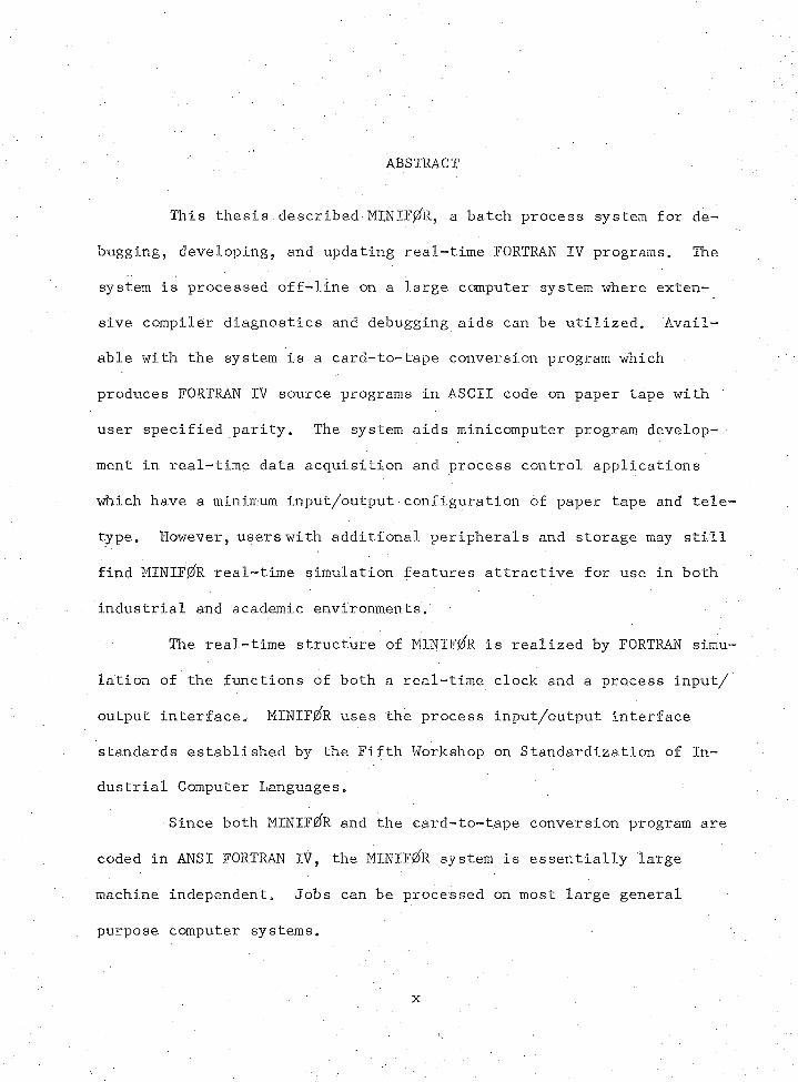
ABSTRACT
This thesis.described MINIF0R, a batch process system for de
bugging 9 developing, and updating real-time FORTRAN IV programs. The
system is processed off-line on a large computer system where exten
sive compiler diagnostics and debugging aids can be utilized. Avail
able with the system is a card-to-tape conversion program which
produces FORTRAN IV source programs in ASCII code on paper tape with
user specified parity. The system aids minicomputer program develop
ment in real-time data acquisition and process control applications
which have a minimum input/output configuration of paper tape and tele
type. However, users with additional peripherals and storage may still
find MINIFffe real-time simulation features attractive for use in both
industrial and academic environments.
The real-time structure of MINIF0R is realized by FORTRAN simu
lation of the functions of both a real-time clock and a process input/
output interface. MINIF0R uses the process input/output interface
standards established by the Fifth Workshop on Standardization of In
dustrial Computer Languages.
Since both MINIF/R and the card-to-tape conversion program are
coded in ANSI FORTRAN IV, the MINIF/R system is essentially large
machine independent. Jobs can be processed on most large general
purpose computer systems.
x
CHAPTER 1
INTRODUCTION
The phenomenal growth of the minicomputer’ industry in the last
decade has resulted from the continuing decrease in the cost of com
ponents. . Progress in the semiconductor and memory technology fields
has been the primary contributor, reducing minicomputer main frame cost
significantly. A leading minicomputer manufacturer recently advertised
(5) that in 1965 one of his models cost $18,000, and to-day a more reli
able line of the same model costs only $4,000. Each of 77 minicomputer
models surveyed by' Murphy (14) was available in the $2,000 to $23,000
price range. This price included a standard processing unit, basic
memory, and occasionally included as standard equipment a teletype, low
speed paper tape read-punch, and real-time clock. This low cost has
now made installation of a small computer very attractive, whereas
previously computer-based alternatives to conventional data acquisition
and control systems were uneconomical. Minicomputer annual shipments
are forecast by Kaenel (8) to grow from 6,000 units in 1969 to 40,000
units by 1975* Approximately half of these units will require real-
time capabilities for data acquisition and process control applica
tions.
. . Motivation
Each minicomputer is programmable in its own assembly language.
Thus, programs developed on one machine are in general not transferable
2
to another machine without extensive modification. While the•existence
of emulator and translator programs does ease assembly language program
ming, Williams (19) has shown that their use is restricted to the as
sembler mode of programming where the minicomputer to be programmed is
emulated on another computer of the same manufacturer, While assembly
language is more efficient from the standpoint of memory requirements
and execution time, the advantages are decreasing as minicomputer main
frame costs continue to drop. This is especially true in areas where
memory requirements or timing considerations are not critical„ In the
early stages of system development companies such as General Electric,
Honeywell, and Westinghouse, as reported by Jarvis (7), Mensh and Diehl
(10), and Roberts (15), respectively, found standard FORTRAN IV inade
quate for real-time applications, However, because FORTRAN had such
influence in the engineering community and had become, in effect, a de
facto standard, these companies as well as others included extensions
to basic FORTRAN IV to facilitate real-time programming in a compiler
level language.
Standardization for some of these extensions has been proposed
by the FORTRAN Committee of the Workshop on Standardization of Indus
trial Computer Languages (ll). The Instrument Society of America (ISA)
accepted these extensions recently (12), Pressure for vendor follow-
through must be gene-rated by user demand as well as ISA publication of
these new real-time standards.
■ Efficiency of real-time FORTRAN program development suffers on
a small computer for several reasons. Efficient compiler operation
cannot be realized in less than 8,000 words of core memory. Even at
this level small computer FORTRAN compilers are extremely simple and do
not produce extensive diagnostics as do compilers on large computer
systems. The.classic debugging aid is the run-time memory dump which
prints the core contents at a stage of computation where execution is
unexpectedly halted. However, the memory dump is not practical for
small machines with very limited input/output devices. Spencer, Shep
ard son, and McGowan (16) report that most minicomputers marketed have
available basic program development software consisting of an assembler,
text editor, loader, and an on-line debugging aid. Of the minicomputer
models surveyed by Murphy (14), 54 had FORTRAN compilers. Program de
velopment on a minimum machine configuration of paper tape and teletype
is awkward and time consuming even with the software aids previously
mentioned<> If control of a process requires the dedication of a small
computer, then on-line program development, debugging, and updating may
not be practical. . Thus, a need exists for an application system which
allows the user to accomplish most program development and debugging
off-line on a large general purpose machine where extensive compiler
diagnostics and debugging aids can be utilized.
An Alternative
This thesis describes an application system that can be used
off-line for program development, debugging, and updating of real-time
FORTRAN IV programs. The system, hereafter called MINIF0R, is envis
aged as an aid in minicomputer real-time data acquisition and process
control applications which have a minimum input/output configuration of
paper tape and teletype. Available with the system is a card-to-tape
conversion program which produces FORTRAN IV source programs in ASCII
(American Standard Code for Information Interchange) code on paper
tape. Options are available for requesting non, even, or odd parity.
tapes. The source program can be transported to the minimum configur
ation small computer for utilization in an actual real-time applica
tion.
Since MINIF^R and card-to-tape conversion program coding is in
ANSI (American National Standards Institute) FORTRAN IV, the MINIF0R
system is essentially large machine independent. Jobs can be processed
on most large general purpose computer systems,
MINIF0R can be utilized by industry to develop and update real
time programs for data acquisition and process control applications.
The system is well suited for applications in laboratory automation,
data acquisition, and process control of chemical and petroleum proc
esses. Also, the real-time simulation features of MINIFjZfR. are appeal
ing for use as an educational tool. The student can use MINIF0R to
investigate or specify a process control strategy for a designated
mathematical model of a process. In laboratories where desired unit
operations equipment is not available, MINIF0R can be used in a data
acquisition application to emulate the process operation needed. In
well equipped laboratories where a.minicomputer and interfacing hard
ware are available, the student can utilize MINIF^R to develop real
time programs to be used in laboratory exercises without the need to
test the program under development against the actual process.
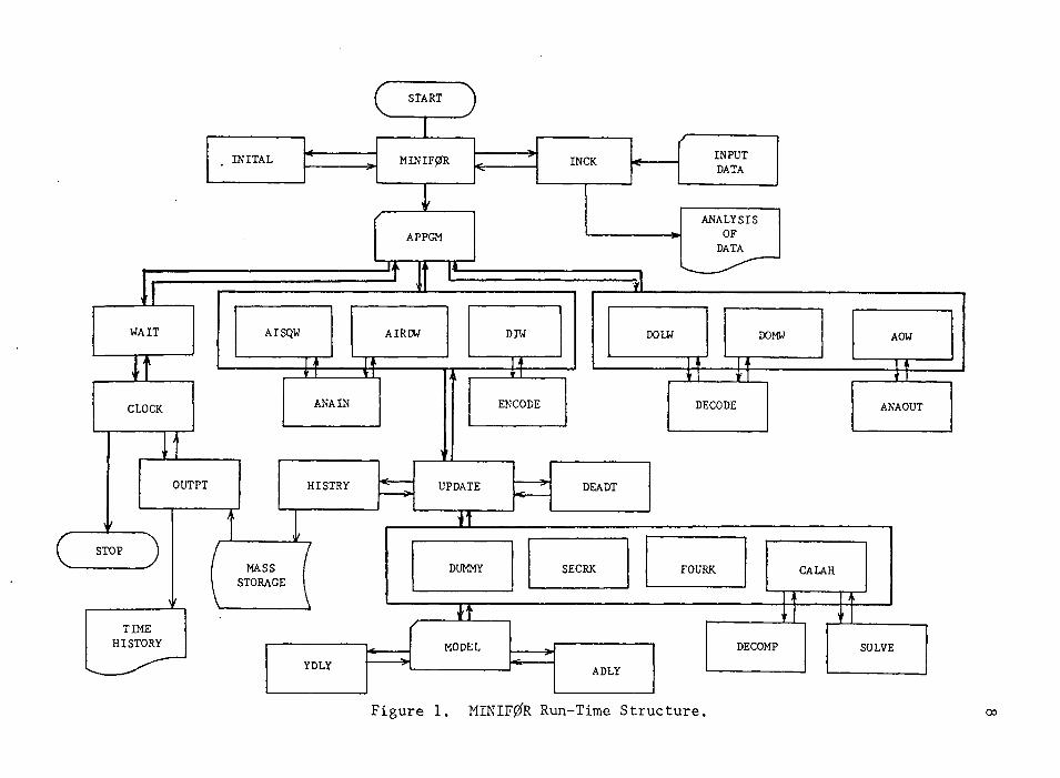
Processing Performed
MINIFgfe processes an application subroutine and any other sub
routines required by the application subroutine. The processing per
formed must be described by a subroutine rather than a main program
because MINIF0R is structured to read and analyze all input data prior
to relinquishing control to the userTs application subroutine, In
order to debug and develop a real-time application subroutine off-line
the application subroutine, .must have a process or environment upon
which to operate. Further, the operation must be on a real-time basis
and include communication to and/or from the process through interfac
ing hardware. This is accomplished within MINIF/R by simulation. The
user provides a model of the process, an application subroutine to op
erate on the process, and input data to describe the simulation and
hardware specifications, The process description may be wholly alge
braic using FORTRAN coding, or it may include dynamic process simula
tion capability using first-order ordinary differential equations in
state variable form. To solve such a dynamic model, MINIF/R calls on
one of three system integration routines selected by the user to update
the process simulation as required by the pseudo real-time input/output
subroutines. MINIF/R allows the user to program disturbances in the
form of step changes entering the process at specified times. Also,■
dead time can be inserted for selected variables. To increase the rel
evance of the simulation, transducer and final control element charac
teristics must be specified as part of the input data.
6
The real-time structure of MINIF0R is realized by simulating
with FORTRAN subroutines the functions of both the real-time clock and
process input and output assembly language handlers. The system emu
lates input of process analog signals to an analog-to-digital converter
(ADC) and output of analog signals to the process from a digital-to-
analog converter (DAC). The emulation of a digital input channel al
lows the position of contact sensors or on-off devices to be monitored.
Emulation of a digital output channel allows digital outputs requiring
a momentary signal and digital outputs which are latched in either the
set or reset state. User.control of real-time execution is accom
plished by simulating delay of execution in a program for a specified
time. To control program execution and communicate with the process
the user must issue calls to system subroutines which perform the de
sired function. These calls conform to the standards established by
the Fifth Workshop on Standardization of Industrial Computer Languages
(11) and accepted by ISA (12).
Real-time processing is accomplished by using the forementioned
calls to input and/or output information from/to the process. The user
may, as in data acquisition systems, interrogate the process for alarm
conditions or operate.on process data as in a chromatograph data analy
sis. If the application is closed-loop process control, then manipu
lated variables are computed and output to the process in the form of
analog signals or digital outputs. MINIF0R is structured to implement
user supplied control algorithms for various types of control, such as
Direct Digital Control (DDC) or Supervisory Set Point control (SSP).
7
Figure 1 illustrates the information paths connecting user sup
plied subroutines and system routines in a simulation run.
Restrictions and Limitations
The restrictions and limitations presented here depend largely
upon the type of processing performed by the user’s application sub
routine and the complexity of the simulation and, hence, may not con
cern all users. Within these limitations MINIF0R can be utilized as a
tool for debugging and developing real-time FORTRAN IV source programs.
MINIF0R is not a translator/compiler program which produces as
sembly language or object code for the user’s minicomputer. Rather,
MINIF0R produces ANSI FORTRAN IV source code. Individual computer
manufacturers provide compilers, with exceptions or extensions to the
ANSI standard due to software or hardware constraints„ Alternatively,
the manufacturers.may provide features not included in ANSI FORTRAN TV.
Therefore, the FORTRAN code used to describe the process and the appli
cation subroutine must be compatible with the batch process machine on
which the MINIF0R application is processed. Further, the application
subroutine must also be compatible with the minicomputer used in the
actual real-time application.
To process a MINIF0R application the user’s application sub
routine must issue calls to ISA standard input/output subroutines im
plemented by MINIFgfR. To process MINIF0R paper tape source programs
on the user’s minicomputer these standard subroutines must also be
available as assembly language handlers on the user’s installation.
^ START ^
. INITA L INCK < ----r ' "
INPUT DATA
< M IN IF 0R ><:-----
APPGM
WAIT
3 T E :l____
ANALYSISOFDATA
AISQW
CLOCK
AIRDW DIM
ANA IN
STOP ^
DOLW
ENCODE
DOMW
DECODE
OUTPT HISTRY UPDATE DEADT
MASSSTORAGE
DUMMY SECRK FOURK
AOW
ANAOUT
CALAH
TIMEHISTORY
YDLYMODEL
ADLYDECOMP SOLVE
Figure 1. MINIF0R Run-Time Structure.
9
The state variable concept is used here for dynamic representa
tion of the process. State equations describing dynamic systems are
restricted to first-order ordinary differential equations.
Not currently implemented is the simulation of priority inter
rupts originating from either the minicomputer operating system or from
the process.
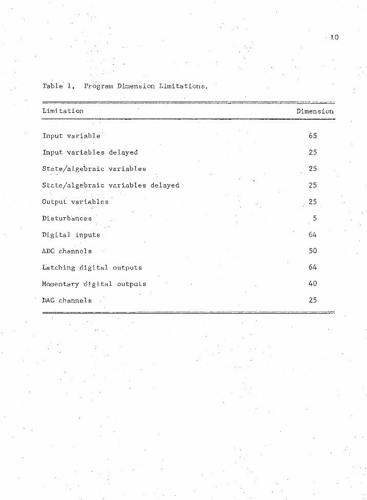
Dimension limitations in MINIF0R are illustrated in Table 1.
MINIF0R can be redimensioned for larger simulations by making minor
changes in the system source code.
Digital input/output registers must not exceed 18 bits in
length. Again, this can be changed with only minor modification of the
source code.
10
Table 1* Program Dimension Limitations„
Limitation Dimension
Input variable 65
Input variables delayed 25
State/algebraic variables 25
State/algebraic variables delayed 25
Output variables . 25
Disturbances 5
. Digital inputs 64
ADC channels 50
Latching digital outputs 64
Momentary digital outputs 40
DAC channels 25
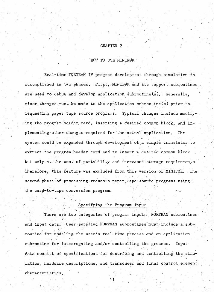
CHAPTER 2
HOW TO USE MINIF0R
Real-time FORTRAN IV program development through simulation is
accomplished in two phasese. First, MINIF0R and its support subroutines .
are used to debug and develop application subroutine(s)„ Generally,
minor changes must be made to the application subroutine(s) prior to
requesting paper tape source programs0 Typical changes include modify
ing the program header card* inserting a desired common block, and im
plementing other changes required for the actual application. The
system could be expanded through development of a simple translator to
extract the program header card and to insert a desired common block
but only at the cost of portability and increased storage requirements.
Therefore, this feature was excluded from this version of MINIF0R. The
second phase of processing requests paper.tape source programs using '
the card-to-tape conversion program.
Specifying the Program Input
There are two categories of program input: FORTRAN subroutines
and input data. User supplied FORTRAN subroutines must include a sub
routine for modeling the user1s real-time process and an application
subroutine for interrogating and/or controlling the process. Input
data consist of specifications for describing and controlling the simu
lation, hardware descriptions, and transducer and final control element
characteristicso
12
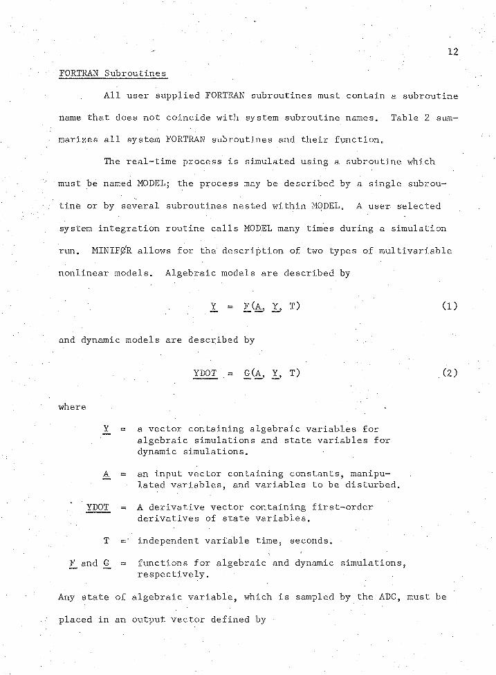
FORTRAN Subroutines
All user supplied FORTRAN subroutines must contain a subroutine
name that does not coincide with system subroutine names. Table 2 sum
marizes all system FORTRAN subroutines and their function.
The real-time process is simulated using a subroutine which
must be named MODEL; the process may be described by a single subrou
tine or by several subroutines nested within MODEL„ A user selected
system integration routine calls MODEL many times during a simulation
run. MINIF0R allows for the description of two types of.multivariable
nonlinear models. Algebraic models are described by
Y = FCA, ■ Y, T) (1)
and dynamic models are described by
YDOT = £(A, Y, T) (2)
where
= a vector containing algebraic variables for algebraic simulations and state variables for dynamic simulations.
A_ = an input vector containing constants5 manipulated variables, and variables to be disturbed.
YDOT = A derivative vector containing first-order derivatives of state variables.
, T = independent variable time, seconds.
F_ and G_ = functions for algebraic and dynamic simulations,respectively.
Any state of algebraic variable, which is sampled by the ADC, must be
placed in an output vector defined by
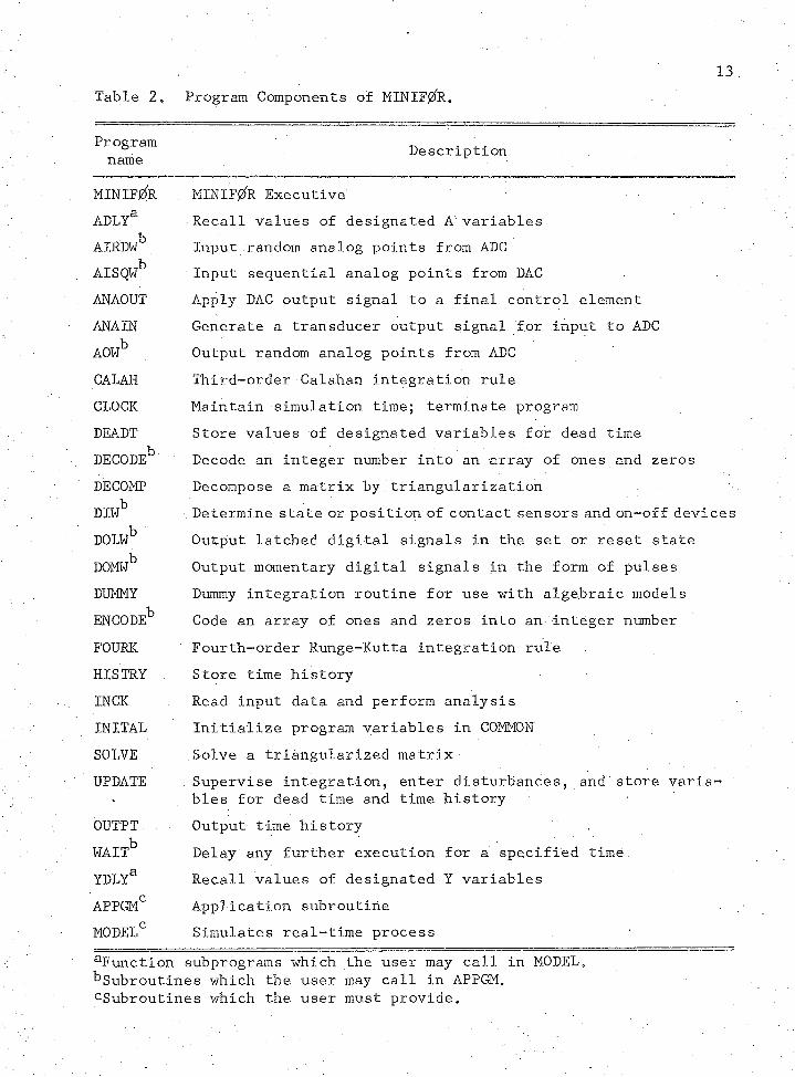
Table 2. Program Components of MINIFjZfR.13
Programname Description
MINIF0R MINIF0R ExecutiveADLYa Recall values of designated A variablesAIRDWb , Input random analog points from ADCAISQWb Input sequential analog points from DACANAOUT Apply,DAC output signal to a final control elementANA IN Generate a transducer output signal for input to ADCAOWb Output random analog points from ADCCALAH Third-order Calahan integration ruleCLOCK Maintain simulation time; terminate programDEALT Store values of designated variables for dead timeDECODEb Decode an integer number into an array of ones and zerosDECOMP Decompose a matrix by triangularizationDIWb • Determine state or position of contact sensors and on-off devicesDOLWb Output latched digital signals in the set or reset stateDOMWb Output momentary digital signals in the form of pulsesDUMMY Dummy integration routine for use with algebraic modelsENCODEb Code an array of ones and zeros into an integer numberFOURK Fourth-order Runge-Kutta integration ruleHISTRY Store time historyINCK Read input data and perform analysisINITAL Initialize program variables in COMMONSOLVE Solve a triangularized matrixUPDATE Supervise integration, enter disturbances, and store varia™
• bles for dead time and time historyOUTPT . Output time historyWAITb Delay any further execution for a specified timeYDLYa Recall values of designated Y variablesAPPGMC Application subroutineMODEL0 Simulates real-time process
unction subprograms which the user may call in MODEL, ^Subroutines which the user may call in APPGM, ^Subroutines which the user must provide.

where _C_ is the output vector and _H is a function. The position of two-
state devices, such as contact sensors or.on-off devices, is described
by a vector IRELAY. A vector element with a value of one represents a
closed contact or a device that is on, while a vector element with a
value of zero represents an open contact or a device that is off. Po
sitions of these devices are monitored on a digital input channel.
FORTRAN statements are used in MODEL to form the vectors.in
equations (l) through (3). Vectors are represented by arrays of the
same variable name. To provide the system with.current values of these
variables, the user must insert the following labeled COMMON block and
DIMENSION statement after the MODEL subroutine header card
COMMON/USER/A, Y, YDOT, IRELAY, C, T-DIMENSION A (65), Y (25), YDOT(25), IRELAY(128), 0(25)
Known functions of time are programmed utilizing the program
variable T. However, the user is cautioned to avoid assigning values
to T, for this is a system function.
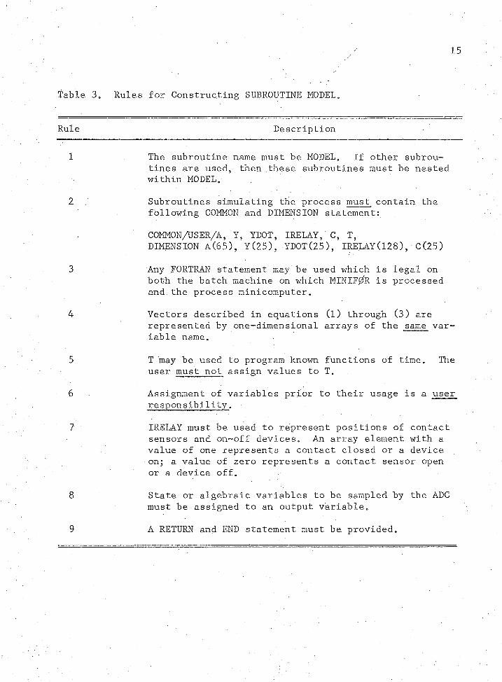
Rules governing the construction of SUBROUTINE MODEL are sum
marized in Table 3.
Simulation of dead time by- MINIFffe is accomplished by storing
values for designated Y and A variables. _ Storage of these variables
is supervised by a system subroutine UPDATE. The user accesses "de
layed" values of these variables in MODEL by using two system function
subprograms, YDLY and ADLY. Their use is described in Table 4.
15
Table 3. Rules for Constructing SUBROUTINE MODEL.
Rule Description
1 The subroutine name must be MODEL. If other subroutines are used, then these subroutines must be nested within MODEL.
2 Subroutines simulating the process must contain the following COMMON and DIMENSION statement:
COMMON/USER/A, Y, YDOT, IRELAY,.C, T,DIMENSION A(65), Y(25), YD0T(25), IRELAY(128), C(25)
3 Any FORTRAN statement may be used which is legal on both the batch machine on which MINIF0R is processed and.the process minicomputer.
4 Vectors described in equations (l) through (3) arerepresented by one-dimensional arrays of the same variable name. *
5 T may be used to program known functions of time. The user must not assign values to T.
6 Assignment of variables prior to their usage is a user responsibility.
7 ‘ IRELAY must be used to represent positions of contactsensors and on-off devices. An array element with avalue of one represents a contact closed or a device on; a value of zero represents a contact sensor open or a device off.
8 State or algebraic variables to be sampled by the ADCmust be assigned to an output variable.
9 A RETURN and END statement must be provided.
16
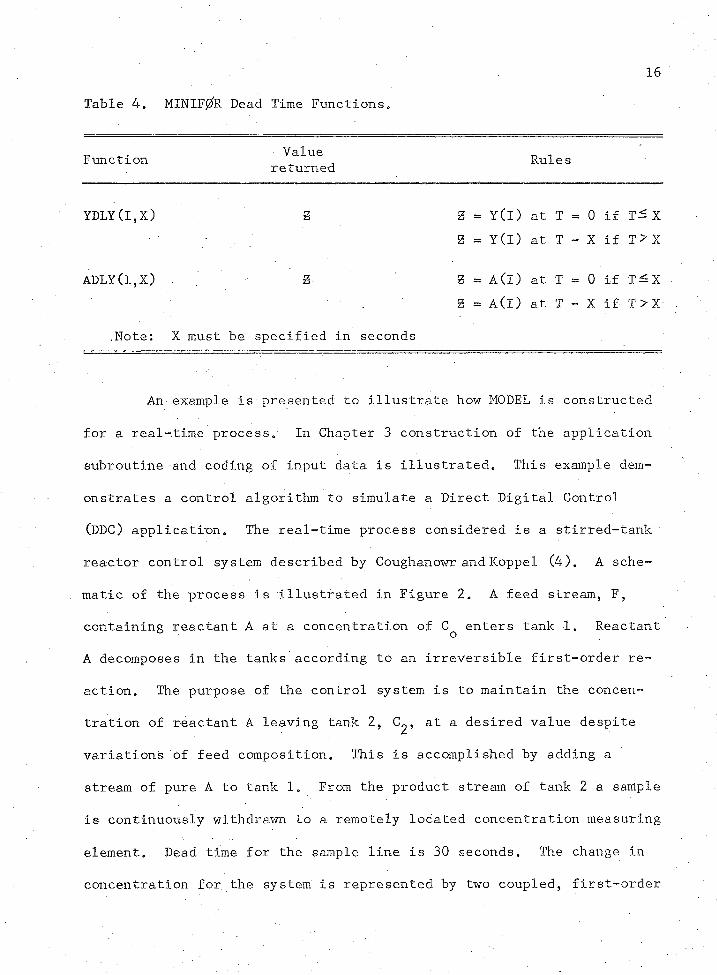
Table 4, MINTF0R Dead Time Functions.
Function Valuereturned Rules
YDLY(l,X) g g = Y(l) at T = 0 if Xg = Y(I) at T - X if T>X
ADLY(I,X) g g = A C l ) at T = 0 if T— X
.Note: X must be specified in seconds
g = a (i ) at T - X if T > X
An example is presented to illustrate how MODEL is constructed
for a real-time process/ In Chapter 3 construction of the application
subroutine and coding of input data is illustrated. This example dem
onstrates a control algorithm to simulate a Direct Digital Control
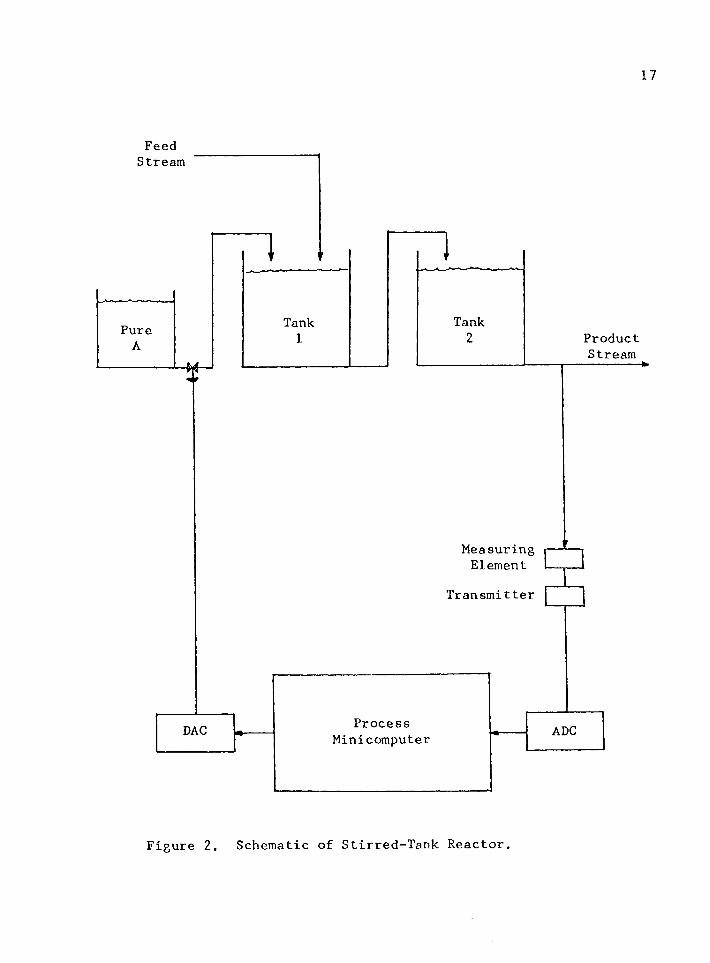
(DDC) application. The real-time process considered is a stirred-tank
reactor control system described by Coughanowr and Koppel (4). A sche
matic of the process is illustrated in Figure 2. A feed stream, F,
containing reactant A at a concentration of C^ enters tank 1. Reactant
A decomposes in the tanks according to an irreversible first-order re
action. The purpose of the control system is to maintain the concen
tration of reactant A leaving tank 2, C , at a desired value despite
variations of feed composition. This is accomplished by adding a
stream of pure A to tank 1. From the product stream of tank 2 a sample
is continuously withdrawn to a remotely located concentration measuring
element. Dead time for the sample line is 30 seconds. The change in
concentration for the system is represented by two coupled, first-order
17
FeedStream
TankTankPure ProductStream
MeasuringElement
Transmitter
DAC ADCProcessMinicomputer
Figure 2. Schematic of Stirred-Tank Reactor.
18
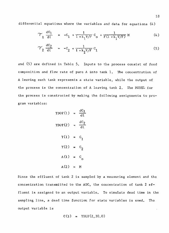
differential equations where the variables and data for equations (4)
^ 1 "dt" = “C1 + 1 +k1V/F Co + F(l +k1V/F) M (4)
dCo 12 "dt" = "C2 + 1 +kgV/F C1
and (5) are defined in Table 5. Inputs to the process consist of feed
composition and flow rate of pure A into tank 1. The concentration of
A leaving each tank represents a state variable, while the output of
the process is the concentration of A leaving tank 2. The MODEL for
the process is constructed by making the following assignments to pro
gram variables:dCiYD0T(1)
YDOT(2)dc2dt
Y(l) = C1
Y(2) = C2
A(l) = Co
A ( 2 ) = M
Since the effluent of tank 2 is sampled by a measuring element and the
concentration transmitted to the ADC, the concentration of tank 2 ef
fluent is assigned to an output variable. To simulate dead time in the
sampling line, a dead time function for state variables is used. The
output variable is
C(3) = YDLY(2, 30.0)
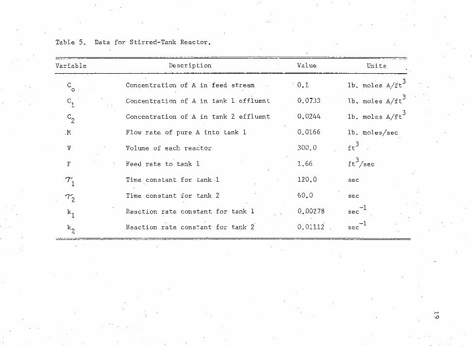
Table 5. Data for Stirred-Tank Reactor.
Variable Description Value Units
co Concentration of A in feed stream 0.1 lb. moles A/ft3
ci Concentration of A in tank 1 effluent 0.0733 lb. moles A/ft3
C2 Concentration of A in tank 2 effluent 0.0244 lb. moles A/ft3
.M Flow rate of pure A into tank 1 0.0166 lb. moles/sec
V Volume of each reactor 300.0 ft3 .
F Feed rate to tank 1 1.66 ft^/sec
Time constant for tank 1 120.0 sec
^2 Time constant for tank 2 60.0 sec
kl Reaction rate constant for tank 1 0.00278 —1sec
k9 Reaction rate constant for tank 2 0.01112 . "1sec
20
SUBROUTINE MODEL for the stirred-tank reactor is illustrated in Fig
ure 3.
The user's application subroutine determines the type of real
time processing performed by the simulation run. Details for con
structing this subroutine are presented in the section on Specifying
the Processing Desired.
Input Data
The amount of data input is dependent upon the type of process
ing performed and the complexity of the simulation. Data are input us
ing the MINIF0R Coding Forms illustrated by Figures 17 to 29 in Appendix
Be Do not remove these forms from this thesis. Instead, make copies
as needed. Each form represents a single card to be coded. Cards 1
through 3 must be supplied for all simulations. Each card is discussed
in detail in this section.
Cards 1, 2, and 3 consist of simulation and hardware specifica
tions. Default conditions exist for many items, and processing is at
tempted if at all possible. An analysis of the data input on these
cards is made by the system. Results are printed with error conditions
and comments noted. If fatal errors are present, the program is ter
minated for error correction and resubmission. If fatal errors are not
present, a card inventory is printed to identify the order and number
of each type of card which the program expects to read.
Card 1 consists of a title and identification which is read in
alphanumeric format and printed at the top of each page of system out
put.

S U B R O U T I N E M O D E LC O M M O N / U S E R / A , Y , Y O O T , I R E L A Y , C , TD I M E N S I O N A ( 6 5 ) , Y ( 2 5 ) , Y D O T ( 2 5 ) , I R E L A Y ( 1 2 8 ) , 0 ( 2 5 )C C H A N G E I N C O N C E N T R A T I O N O F T A N K 1 E F F L U E N TY D O T ( l ) = - ( Y ( i ) / 1 2 Q • ) + ( A d ) / < l # + O e G 0 2 7 3 * 3 0 C # / 1 . 6 6 ) ) / 1 2 3 1 ( ( A ( 2 ) * . 8 / ( 7 . 4 8 * 6 3 . ) ) / ( 1 . 6 6 * ( 1 . * 3 . C G 2 7 8 * 3 0 C . / 1 . 6 6 ) ) ) / 1 2 0 .C C H A N G E I N C O N C E N T R A T I O N O F T A N K 2 E F F L U E N TY D O T ( 2 ) = - ( Y ( 2 ) / 6 0 . 0 ) + ( Y d ) / d . + C . 0 1 1 1 2 * 3 0 , J . / 1 . 6 6 ) ) / 6 3 C A S S I G N O U T P U T V A R I A B L EC N O T E U S E O F D E A D T I M E F U N C T I O N F O R D E L A Y I N S A M P L I N G L I N EC C D = Y d )C (2) = Y (2)C ( 3 ) = Y D L Y ( 2 , 3 0 . 3 )R E T U R NE N D
Figure 3. MODEL for Stirred-Tank Reactor.
22
Instructions for coding Card 2 are presented in Table 6.
Guidelines for selection and integration routine are presented in Ap
pendix C, as well as a caution in using Calahan1s method with time
varying systems. If SUBROUTINE MODEL does not contain state varia
bles, code item 12A as DUM. For dynamic simulations code RK2, RK4, or
CAL for the desired integration routine.
Instructions for coding Card 3 are summarized in Table. 7.
Specification of .items 6A, 6B, and 6C allows the system to simulate
pulse outputs. MINIF0R simulates pulse outputs from a digital regis
ter to a stepping motor/integrating amplifier which outputs a DC sig
nal to a final control element.
Instructions for coding Cards 4 through 13 are summarized on
each coding form. Details are presented here.
Card 4 specifies initial conditions for input variables. In
clude manipulated variables and set points manipulated by final control
elements receiving a DC signal from a DAC; also, include constants if
desired. Initial conditions for input variables manipulated by pulse
outputs are specified on Card 13.
Card 5 specifies initial conditions for state or algebraic var
iables at time T = 0. Initial conditions for these variables are re
quired by the system for storage in the time history and the dead time
‘tables.
Card 6 specifies the initial state or position of contact sen
sors and on-off devices. Code one card to specify the initial state
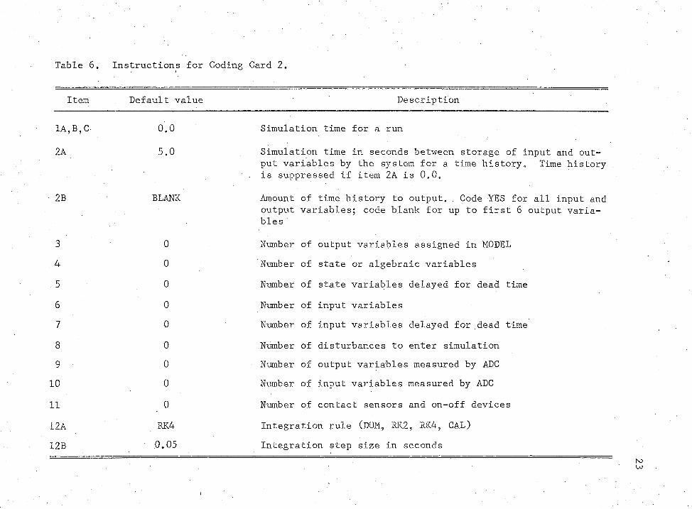
Table 6„ Instructions for Coding Card 2.
Item Default value Description
1A,B,C 0.0 Simulation time for a run
2A 5.0 Simulation time in seconds between storage of input and output variables by the system for a time history. Time history
- is suppressed if item 2A is 0.0.
2B BLANK Amount of time history to output. Code YES for all input and output variables; code blank for up to first 6 output variables
3 0 Number of output variables assigned in MODEL. 4 0 Number of state or algebraic variables. 5 0 Number of state variables delayed for dead time6 0 Number of input variables7 0 Number of input variables delayed for dead time8 0 Number of disturbances to enter simulation9 0 Number of output variables measured by ADC10 0 Number of input variables measured by ADC
11 0 Number of contact sensors and on-off devices
12A RK4 Integration rule (DUM, RK2, RK4, CAL)12B 0.05 Integration step size in seconds
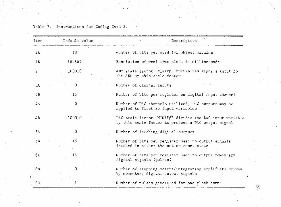
Table 7e Instructions for Coding Card 30
Item Default value Description
1A 18 Number of bits per word for object machine
IB 16.667 ' Resolution of real-time clock in milliseconds
2 1000.0 ADC scale factor; MINIF0R multiplies signals input to the ADC by this scale factor
3A 0 Number of digital inputs
3B 16 Number of bits per register on digital input channel
4A 0 Number of DAC channels utilized, DAC outputs may be applied to first 25 input variables
4B 1000.0 DAC scale factor; MINIF0R divides the DAC input variable by this scale factor to produce a DAC output signal
5A 0 Number of latching digital outputs
5B 16 Number of bits per register used to output signals latched in either the set or reset state
6A 16 Number of bits per register used to output momentary digital signals (pulses)
6B 0 Number of stepping motors/integrating amplifiers driven by momentary digital output signals
6C 1 Number of pulses generated for one clock count
.25
for digital inputs represented by elements 1 through 64 of IRELAY. If
latching digital outputs are made, code an additional card to specify
the initial state for elements 65 through 128 of IRELAY. The user is
responsible for keeping track of which bit position in the input and
output register is connected to each element of IRELAY.
Card 7 specifies information for programming disturbances in a
simulation. Three items are required to specify one disturbance. The
first item designates the input variable receiving the step change.
The second item gives the time in seconds when the input variable is
changed. Item three specifies the new value of the input variable.
Any input variable may be programmed for a step change, and a single
variable may be changed as many times as desired, providing the number
of such disturbances does not exceed 5.
Cards 8 and 9 specify information for programming dead time in
a simulation. Use Card 8 for input variables and Card 9 for state/
algebraic variables. Two items are required to specify dead time for
one variable. The first item designates the variable. Any of the
first 25 A variables may be designated on Card 8 and any Y variable may
be designated on Card 9. The second item specifies the dead time in
seconds for the designated variable.
Cards 10 and 11 specify the characteristics of transducer out
puts to the ADC and channel connections for these signals. MINIF/R
utilizes these specifications to generate analog signals for designated
measured input and output variables. Inputs on the coding sheets are
discussed from left to right. First, the variable measured is
26
designated; Card 10 is used for output variables and Card 11 for input
variables. Next, the user specifies engineering units. Minimum and
maximum values of the measured variable are next specified; these val
ues correspond to the range of the measured variable for the input span
of the transducer. MINIFj2fR allows for the representation of nonlinear
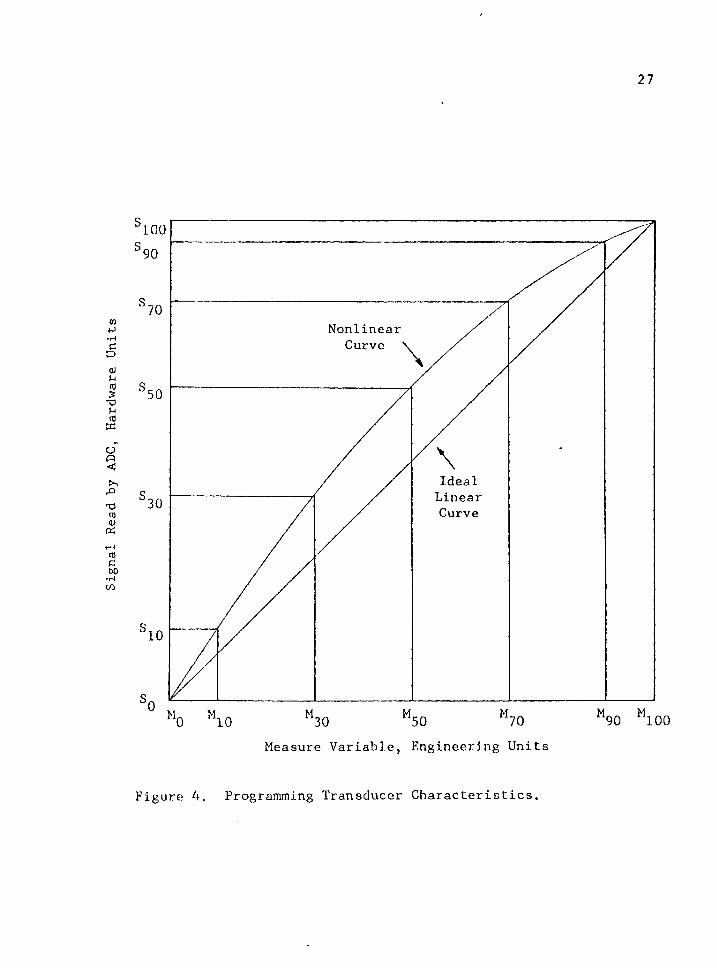
transducer outputs as described by Marks and Skillern (9). Figure 4
illustrates the technique; the measured variable is M and the signal in
hardware units read by the computer is S. Hardware units could be
milHamperes, volts, or percent of full scale. Nonlinearities are rep
resented by specifying the seven ordinate points, through S- qqj in
Figure 4. The system interpolates linearly between points. If a
transducer output is linear, then specify only and the system
generates and stores S^q through S^q . Finally, the user designates the
channel number on which the variable is measured. Use channels 1
through 25 for measuring output variables and channels 26 through 50
for input variables.
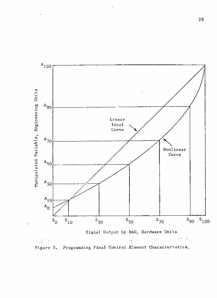
Card 12 specifies channel connections for DAC outputs to final
control elements. MINIF0R utilizes these specifications to change
designated manipulated input variables whenever DAC outputs are used.
Inputs on the coding sheet are discussed from left to right. First,
the input variable manipulated is designated. Next, the user specifies
engineering units for the manipulated variable. MINIF0R allows for the
representation of nonlinear final control element characteristics as
described by Buckley (l). Figure 5 illustrates the nonlinearity of a
valve; .the manipulated variables is represented by A and the signal in
Signal Read by
ADC, Hardware Units
27
100
NonlinearCurve
IdealLinearCurve30
10
100Measure Variable, Engineering Units
Figure 4. Programming Transducer Characteristics.
Manipulated
Variable,
Engineering
Units
28
100
LinearIdealCorve
NonlinearCurve
30
SSSSSSS 1009010Signal Output by DAC, Hardware Units
Figure 5. Programming Final Control Element Characteristics.
29
hardware units from the DAG is S. Nonlinear characteristics are repre
sented by specifying the seven ordinate points, through s^qqj in
Figure 5» The program interpolates linearly between points. If the
characteristics are linear, specify only and S- qq> the system cal
culates and stores through Next, the minimum and maximum DAG
output signals, A^ and A ^ q, are specified. Finally, the user desig
nates the channel number.on which the DAG signal is output.
Proper organization of input variables is important to success
ful execution of the program. Initial program values.for input varia
bles manipulated by DAG outputs are assigned to elements of the A array,
first. This is done using Card 4. If input variables are manipulated
by stepping motors or integrating amplifiers receiving pulse signals,
then the initial level of each input variable is specified on Card 13.
Three items are input for each pulse output. First, specify the ini
tial level of the input variable. Next, specify engineering units for
the input variable. The.third item designates the change, in engineer
ing units, of the input variable per positive pulse.
Specifying the Processing Desired
After the input data have been read and analyzed by the system
routine INCK, MINIF0R calls the user's application subroutine. This
section presents guidelines for successful program implementation and
describes the system subroutines which the user may utilize. The sys
tem subroutines which the user can call are flagged in Table 2.
The user's application may be described by one or more sub
routines, but the control point for the real-time application should be

30
SUBROUTINE APPGM. Typical examples of additional subroutines are con
trol algorithms and output routines for printing alarm conditions or
process reports.
Executive Interfaces
In an actual application the real-time clock is updated by
software or hardware interrupt servicing. In either case the user
would check the time of the real-time clock to determine if it is time
to sample data from the process or perform a desired operation, In
MINIF0R a pseudo real-time clock is advanced when SUBROUTINE CLOCK is
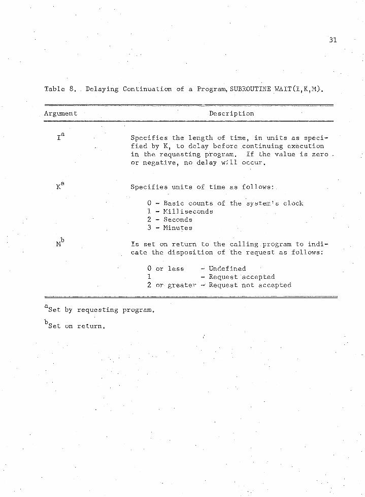
called. The user must never call CLOCK. Instead, the user calls
SUBROUTINE WAIT which delays execution in the calling program for a
specified length of time by issuing a call to CLOCK, incrementing the
program clock, and returning control to the requesting program. The
form of this call is
CALL WAIT (j,K,M) '
where the arguments are described in Table 8. Information for this
table was extracted from Minutes of Fifth Workshop on Standardization
of Industrial Computer Languages (11). WAIT is one of three executive
interface routines accepted by ISA. The other two interface routines,
START and TRNON, are not currently implemented in MINIF^R.
Process Input/Output Interfaces
If real-time processing in a MINIF0R application involves the
input or output of information to or from the process, the user must
issue calls to one of six real-time input/output subroutines. These
31
Table 8„ . Delaying Continuation of a Program, SUBROUTINE WAIT(l,K,M).
Argument Description
ia Specifies the length of time, in units as specified by K, to delay before continuing execution in the requesting program. If the value is zero , or negative, no delay will occur.
Ka Specifies units of time as follows:.
0 - Basic counts of the system's clock1 - Milliseconds2 - Seconds3 - Minutes
Mb Is set on return to the calling program to indicate the disposition of the request as follows:
0 or less - Undefined1 - Request accepted2 or greater - Request not accepted
aSet by requesting program.
Set on return.
subroutine names and argument lists conform to process input and output
standards established by the Fifth Workshop on Standardization of In
dustrial Computer Languages. By issuing a call to one of these sub
routines the user simulates transferring either analog or digital sig
nals to or from the process. In the actual minicomputer real-time
application these same subroutines must be implemented as assembly
language handlers which issue input/output transfer statements to in
terfacing hardware such as an analog-to-digital converter. In MINIF0R
the functions of these assembly language handlers are simulated byi
FORTRAN subroutines having identical subprogram names and argument
lists. Tables .9 through 14 summarize the subprogram names and argument
lists for these standard input and output interfaces. The information
in these tables was extracted from the Minutes of the Fifth Workshop on
Standardization of Industrial Computer Languages (11).
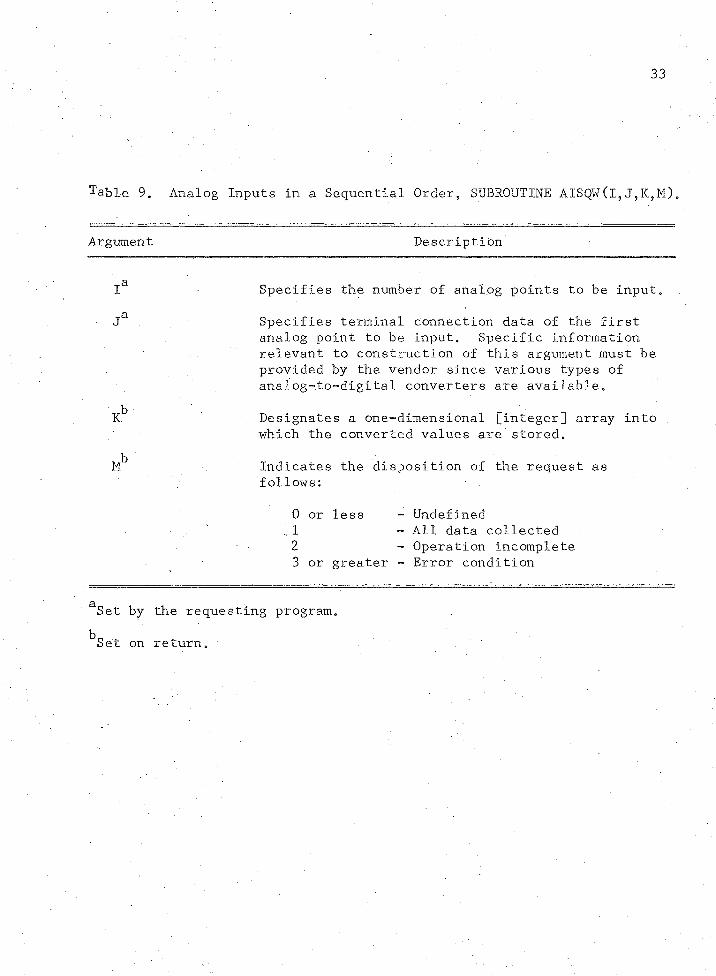
Standard input and output interfaces established by the Fifth
Workshop allow for two forms. The first form accommodates executive
systems which permit overlapped input/output and processing; the second
form accommodates executive systems which suspend execution in the re
questing program until the process input or output is completed. The
second form is flagged by the addition of a W as the last letter in
the subroutine name. MINIF0R accommodates only the second form. If
the minicomputer executive system requires use of the first form, then
prior to requesting punched paper tape source programs the ’W 11 in the
subroutine name should be dropped.
33
Table 9. Analog Inputs in a Sequential Order, SUBROUTINE AISQW(l,
Argument Description
ia Specifies the number of analog points to be input.
ja Specifies terminal connection data of the first analog point to be input. Specific information relevant to construction of this.argument must be provided by the vendor since various types of analog~.to~digital converters are available.
Kb Designates a one-dimensional [integer] array into which the converted values are stored.
Mb Indicates the disposition of the request as follows:
0 or less - Undefined .. 1 - All data collected2 - Operation incomplete3 or greater - Error condition
aSet by the requesting program.
^Set on return.

34
Table 10. Analog Inputs in a Random Order, SUBROUTINE AIRDW(l,
Argument Description
ia Specifies the number of analog points to be input.
ja Specifies terminal connection data for each analog point to be input. Specific information relevant to construction of this argument must be provided by the vendor.
Kb Designates a one-dimensional [integer] array into which the converted values are stored.
Mb Indicates the disposition of the request as follows:
0 or less ~ Undefined1 - All data collected2 - Operation incomplete3 or greater - Error condition
aSet by the requesting program*bSet on return,
35
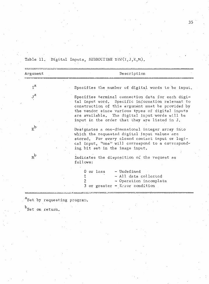
Table 11. Digital Inputs, SUBROUTINE DIW(l,J,K,M).
Argument Description
Ia Specifies the number of digital words to be input.
Ja Specifies terminal connection data for each digital input word. Specific information relevant to construction of this argument must be provided by the vendor since various types of digital inputs are available. The digital input words will be input in the order that they are listed in J.
Kb Designates a one-dimensional integer array into which the requested digital input values are stored. For every closed contact input or logi^ cal input, "one" will correspond to a corresponding bit set in the image input.
Mb Indicates the disposition of the request as follows:
0 or less - Undefined1 - All data collected2 - Operation incomplete3 or greater - Error condition
aSet by requesting program.bSet on return.
36
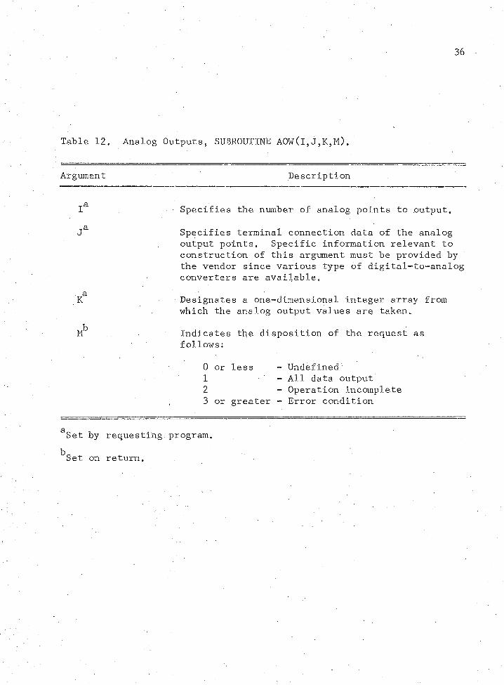
Table 12. Analog Outputs, SUBROUTINE AOWCl,
Argument Description
ia . ‘ Specifies the number of analog points to .output.
ja Specifies terminal connection data of the analog output points. Specific information relevant to construction of this argument must be provided by the vendor since various type of digital-to-analog converters are available.
K8 Designates a one-dimensional integer array from which the analog output values are taken.
Mb Indicates the disposition of the request as follows:
0 or less - Undefined1 - All data output2 - Operation incomplete3 or greater - Error condition
aSet by requesting program.
^Set on return.
37
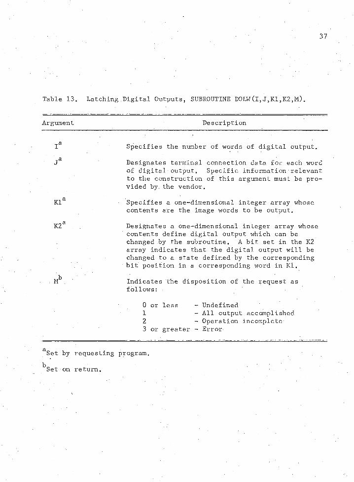
Table 13. Latching Digital Outputs, SUBROUTINE DOLW(l,J,K1,K2,M).
Argument Description
; la Specifies the number of words of digital output.
Ja Designates terminal connection data for each word of digital output. Specific information relevant to the construction of this argument must be provided by the vendor.
Kla Specifies a one-dimensional integer array whose contents are the image words to be output.
K2a Designates a one-dimensional integer array whose contents define digital output which can be changed by the subroutine. A bit set in the K2 array indicates that the digital output will be changed to a state defined by the corresponding bit position in a corresponding word in Kl.
- Mb ,. Indicates the disposition of the request as follows:
0.or less - Undefined1 - All output accomplished2 - Operation incomplete3 or greater - Error
aSet by requesting program.
Set on return.
38
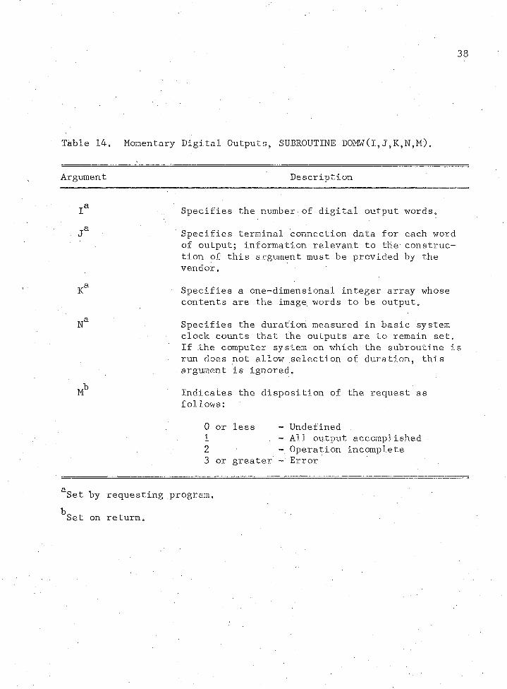
Table 14. Momentary Digital Outputs, SUBROUTINE DOMW(l,J,K,N,M).
Argument Description
■ ia Specifies the number of digital output words.
ja Specifies terminal connection data for each word of output; information relevant to the construction of this argument must be provided by the vendor.
Ka Specifies a one-dimensional integer array whose contents are the image words to be output.
Na Specifies the duration measured in basic system clock counts that the outputs are to remain set. If the computer system on which the subroutine is run does not allow selection of duration5 this . argument is ignored.
Mb Indicates the disposition of the request as follows:
0 or less - Undefined1 - All output accomplished.2 - Operation incomplete3 or greater - Error
aSet by requesting program.
^Set on return.

39
Analog inputs are directed to an analog-to-digital converter
(ADC); MINIF^R allows addressing up to fifty channels. Analog points
are input sequentially using the following call:
CALL AISQW(I,J,K,M)
where the arguments are described in Table 9. Alternatively5 analog
points are input randomly using
CALL AIRDW(I,J,K,M)
where these arguments are described in Table 10. Argument J is an in
teger array of channels to be converted.
A digital input is connected to one bit position of an m bit
digital input register. The entire register is then input as a single
word. MINIF0R allows addressing of up to n digital input registers
such than mxn 64.
The user is responsible for setting bit positions of a register
by assigning one or zero to the corresponding element of IRELAY. Ele
ments 1 through 64 of IRELAY are reserved for digital inputs which are
then accessed by the following call:
CALL DIW(I,
where these arguments are described in Table 11.
Analog outputs are directed to a digital-to-analog converter
(DAC); MINIF0R. allows for addressing up to twenty-five channels. Ana
log points are output randomly by issuing the following call:
40
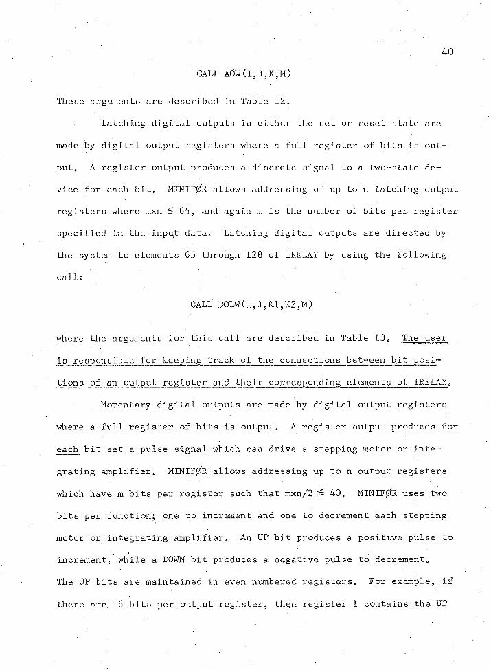
CALL A0W(I,J,K,M)
These arguments are described in Table 12,
Latching digital outputs in either the set or reset state are
made by digital output registers where a full register of bits is out
put* A register output produces a discrete signal to a two-state de
vice for each bit. MINIFffe allows addressing of up ton latching output
registers where mxn fz 64, and again m is the .number of bits per register
specified in the input data. Latching digital outputs are directed by
the system to elements 65 through 128 of IRELAY by using the following
call:
CALL D0LW(I,J,K1,K2,M)
where the arguments for this call are described in Table 13. The user
is responsible for keeping track of the connections between bit posi
tions of an output register and their corresponding elements of IRELAY.
Momentary digital outputs are made by digital output registers
where a full register of bits is output. A register output produces for
each bit set a pulse signal which can drive a stepping motor or inte
grating amplifier. MINIF0R allows addressing up ton output registers
which have m bits per register such that mxn/2 40. MINIF0R uses two
bits per function; one to increment and one to decrement each stepping
motor or integrating amplifier. An UP bit produces a positive pulse to
increment, while a DOWN bit produces a negative pulse to decrement.
The UP bits are maintained in even numbered registers. For example, if
there are 16 bits per output register, then register 1 contains the UP
41
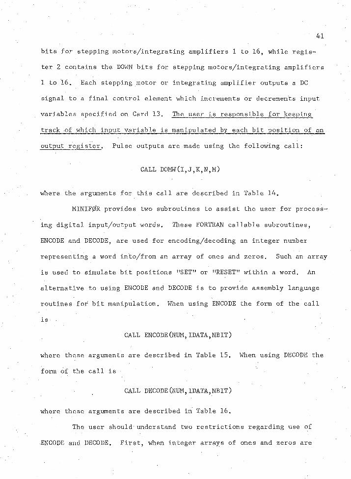
bits for stepping motors/integrating amplifiers 1 to 16, while regis
ter 2.contains the DOWN bits for stepping motors/integrating amplifiers
1 to 16. Each stepping motor or integrating amplifier outputs a DC
signal to a final control element which increments or decrements input
variables specified on Card 13. The user is responsible for keeping
track of which input variable is manipulated by each bit position of an.
output register. Pulse outputs are made using the following call:
CALL D0MW(I,J,K,N,M)
where the arguments for this call are described in Table 14.
M1NIF0R provides two subroutines to assist the user for process
ing digital input/output words. These FORTRAN callable subroutines,
ENCODE and DECODE, are used for encoding/decoding an integer number
representing a word into/from an array of ones and zeros. Such an array
is used to simulate bit positions "SET" or "RESET" within a word. An
alternative to using ENCODE and DECODE is to provide assembly language
routines for bit manipulation. When using ENCODE the form of the call
is ■ ■
CALL ENCODE(NUM,IDATA,NBIT)
where these arguments are described in Table 15. When using DECODE the
form of the call is
CALL DECODE(NUM,IDATA,NBIT)
where these arguments are described in Table 16.
The user should understand two restrictions regarding use of
•ENCODE and DECODE. First, when integer arrays of ones and zeros are
42
Table 15, Encoding an Integer Array„
Argument Description
NUMa An integer number representing an image word produced from the integer array of ones andzeros.
IDATAb An integer array of ones and zeros to be coded into an integer number.
NBITb Specifies the number of bits per image word.
aSet on return.
^Set by the requesting program.
Table 16, Decoding an Integer Number.
Argument Description
NUMa . An integer number to be decoded into an integer array of ones and zeros.
IDATAb An integer array of ones and zeros produced from decoding NUM.
NBITa Specifies the number of bits per image word.
Set by the requesting program.
Set on return.
43
processed by the system, the lowest numbered element of the integer ar
ray corresponds to the most significant bit of the word. Secondly,
since the corresponding argument for IDATA in ENCODE and DECODE is di
mensioned to 18, the user must dimension IDATA to 18 in his application
subroutine. This restriction is imposed because some compilers require
that an array passed as an argument must be equally dimensioned in the
requesting program as in the program being called.
Submitting a Processing Request
Program components comprising MINIF0R are stored'in both source
and object form on magnetic tape at The University of Arizona Computer
Center. Prospective users external to The University of Arizona should
contact the Chemical Engineering Department concerning access to the
system.
Processing at The University of Arizona
Processing .on campus is performed on the University Computer Cen
ter's Control Data Corporation 6400 under the SCOPE 3.3 operating sys
tem. A sample run deck with control card sequence is illustrated in
Figure 6. The TP parameter is required on the Job Card for the system
tape. Most jobs can be processed .in less than 70,000^ words of central
memory. Under the present job priority structure, a central'memory re
quest of greater than 70,000^ increases turnaround time to one day.
The job name, billing number, and MINIF0R system tape number must be
specified by the user.

JOBNAME,TP1,CM70000,BNYYYYYYYY.
REQUEST(TAPE1,HI,RO) MTAPE
REWIND(TAPE1)
C0PYBF(TAPE1,MINI)
UNLOAD(TAPE1)
FTN(B=USER)
LOAD(MINI)
LOAD(USER)
EXECUTE(MINIF0R)
SUBROUTINE MODEL
SUBROUTINE APPGM
Other user supplied FORTRAN subroutines
MINIF0R input data cards
Optional input date read by user subroutines
6-7-8--9 Card
7-8-9 Card
y//
/
7-8-9 Card
Figure 6. Sample Run Deck for MINIF0R
45
Processing at Other Installations
Since all MINIF0R coding is ANSI FORTRAN IV, the program is es
sentially machine independent and can be processed on most computers
with sufficient memorye Compilation of MINIF0R, without APPGM and
MODEL, on a GDC 6400 produces object code requiring 50,000g words,
where one real variable is stored in one 60-bit word. Processing on
smaller systems can be realized by overlaying sections of MINIF0R.
This will require modification of the source code. The system requires
a mass storage device for temporary storage of the time history while a.
job is being processed. Data are transmitted to/from this device using
an unformatted WRITE and READ statement. Prior to program termination
a REWIND is executed, and the time history is printed. Disk or drum
may be used for temporary storage rather than magnetic tape if the in
stallation operating system permits application of REWIND to random ac
cess files.
MINIF0R input/output statements have variable equipment unit
numbers which are passed through COMMON to all system subroutines.
These unit numbers are initialized by subroutine INITAL prior to read
ing input data. The assigned unit numbers are listed in Table 17.
Table 17. MINIF0R Input/Output Unit Assignments.
Unit variable Assigned value Input/output equipment
ICDRD 2 Card reader
IPR 4 Printer
ITAPE 7 Mass storage device
46
Users at other installations wishing to use different input/
output unit assignments should change the assignment of the unit vari
able in SUBROUTINE INITAL and change the MINIF0R main program header
card.
Error Correction and Resubmission
MINIF0R provides diagnostics to facilitate error correction and
resubmission. Diagnostics are printed when data are input and default
values are assigned. Fatal errors detected by the pseudo real-time •
input/output subroutines and the implicit Calahan integration routine
abort the job. All MINIF0R diagnostics and fatal errors are summarized
in Table 18.
Errors in the Input Data,
If the program is terminated after Cards 1 through 3 have been
processed, then fatal errors have been detected. System printout of
the data analysis identifies the fatal error for correction and job
resubmission. If there are no fatal errors, then a card inventory is
printed and the remaining input data cards are read and processed. If
an error has occurred while reading Cards 4 through 13, then utilize
the card inventory to identify cards out of order and extra or missing
cards.
Abnormal Termination
The argument list of the pseudo real-time input/output sub
routines identifies the number of words and channel number for each
word to be transferred. If an attempt is made to transfer too many
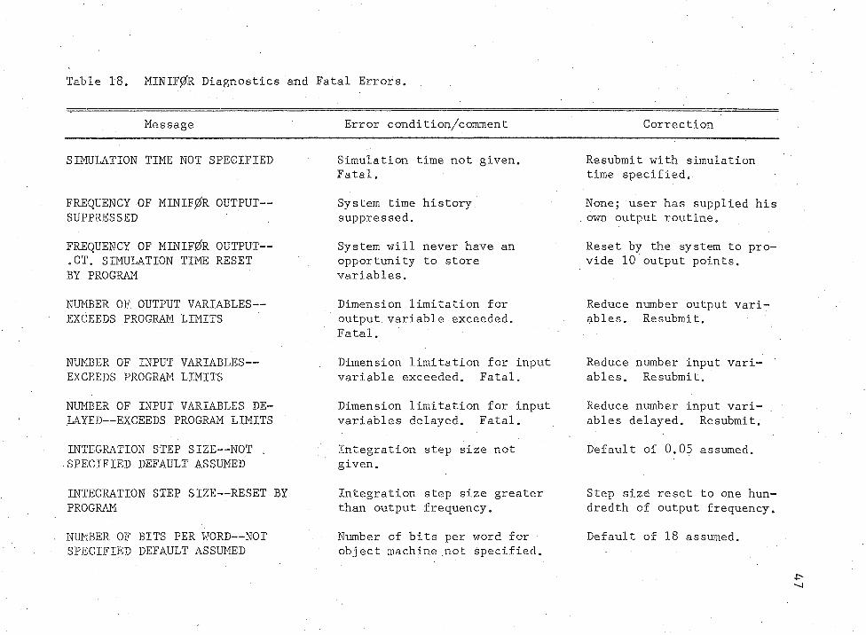
Table 18. MINIF0R Diagnostics and Fatal Errors.
Message Error condition/comment Correction
SIMULATION TIME NOT SPECIFIED
FREQUENCY OF MINIF0R OUTPUT— SUPPRESSED
FREQUENCY OF MINIF0R OUTPUT— .GT. SIMULATION TIME RESET BY PROGRAM
Simulation time not given. Fatal.
System time history. suppressed.
System will never have an opportunity to store variables.
Resubmit with simulation time specified.,
None; user has supplied his own output routine.
Reset by the system to provide 10 output points.
NUMBER OF OUTPUT VARIABLES— EXCEEDS PROGRAM LIMITS
NUMBER OF INPUT VARIABLES— EXCEEDS PROGRAM LIMITS
NUMBER OF INPUT VARIABLES DELAYED— EXCEEDS PROGRAM LIMITS
INTEGRATION STEP SIZE— NOT , SPECIFIED DEFAULT ASSUMED
INTEGRATION STEP SIZE— RESET BY PROGRAM
NUMBER OF BITS PER WORD— NOT SPECIFIED DEFAULT ASSUMED
Dimension limitation for output variable exceeded. Fatal,
Dimension limitation for input variable exceeded. Fatal.
Dimension limitation for input variables delayed. Fatal.
Integration step size not given.
Integration step size greater than output frequency.
Number of bits per word for object machine not specified.
Reduce number output variables. Resubmit.
Reduce number input variables. Resubmit.
Reduce number input variables delayed. Resubmit.
Default of 0.05 assumed.
Step size reset to one hundredth of output frequency.
Default of 18 assumed.
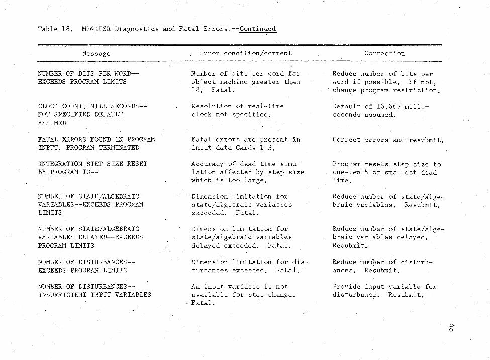
Table 18. MINIFgfR Diagnostics and Fatal Errors.— Continued
Message Error condition/comment . Correction
NUMBER OF BITS PER WORD— EXCEEDS PROGRAM LIMITS
CLOCK COUNT, MILLISECONDS— NOT SPECIFIED DEFAULT ASSUMED
FATAL ERRORS FOUND IN PROGRAM INPUT, PROGRAM TERMINATED
INTEGRATION STEP SIZE RESET BY PROGRAM TO—
NUMBER OF STATE/ALGEBRAICVARIABLES— EXCEEDS PROGRAM LIMITS
NUMBER OF STATE/ALGEBRAIC VARIABLES DELAYED— EXCEEDS PROGRAM LIMITS
NUMBER OF DISTURBANCES— EXCEEDS PROGRAM LIMITS
NUMBER OF DISTURBANCES— INSUFFICIENT INPUT VARIABLES
Number of bits per word for object machine greater than 18. Fatal.
Resolution of real-time clock not specified.
Fatal errors are present in input data Cards 1-3.
Accuracy of dead-time simulation affected by step size which is too large.
Dimension limitation for state/algebraic variables exceeded. Fatal.
Dimension limitation for state/algebraic variables delayed exceeded. Fatal.
Dimension limitation for disturbances exceeded. Fatal.
An input variable is not available for step change. Fatal.
Reduce number of bits per word if possible. If not, change program restriction.
Default of 16.667 milliseconds assumed.
Correct errors and resubmit.
Program resets step size to one-tenth of smallest dead time.
Reduce number of state/algebraic variables. Resubmit.
Reduce number of state/algebraic variables delayed. Resubmit.
Reduce number of disturbances, Resubmit.
Provide input variable for disturbance. Resubmit.
oo
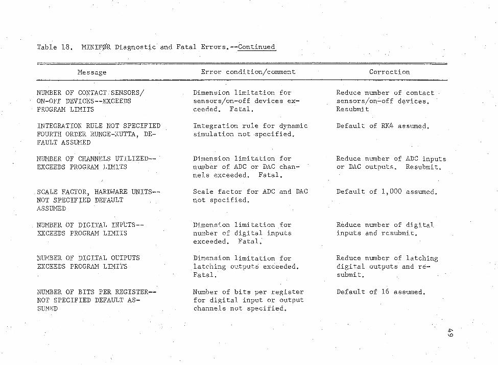
Table 18, MIN1F0R Diagnostic and Fatal Errors.-— Continued
Message Error condition/comment Correction
NUMBER OF CONTACT SENSORS/ ON-OFF DEVICES— EXCEEDS,PROGRAM LIMITS
INTEGRATION RULE NOT SPECIFIED FOURTH ORDER RUNGE-KUTTA, DEFAULT ASSUMED
NUMBER OF CHANNELS UTILIZED— EXCEEDS PROGRAM LIMITS
SCALE FACTOR, HARDWARE UNITS— NOT SPECIFIED DEFAULT ASSUMED
NUMBER OF DIGITAL INPUTS — EXCEEDS PROGRAM LIMITS
NUMBER OF DIGITAL OUTPUTS EXCEEDS PROGRAM LIMITS
NUMBER OF BITS PER REGISTER— NOT SPECIFIED DEFAULT ASSUMED
Dimension limitation for sensors/on-off devices exceeded. Fatal.
Integration rule for dynamic simulation not specified.
Dimension limitation for number of ADC or DAC channels exceeded. Fatal.
Scale factor for ADC and DAC not specified.
Dimension limitation for number of digital inputs exceeded. Fatal.
Dimension limitation for latching outputs exceeded. Fatal.
Number of bits per register for digital input or output channels not specified.
Reduce number of contact sensors/on-off devices. Resubmit
Default of RK4 assumed.
Reduce number of ADC inputs or DAC outputs. Resubmit.
Default of 1,000 assumed.
Reduce number of digital inputs and resubmit.
Reduce number of latching digital outputs and resubmit.
Default of 16 assumed.
\o
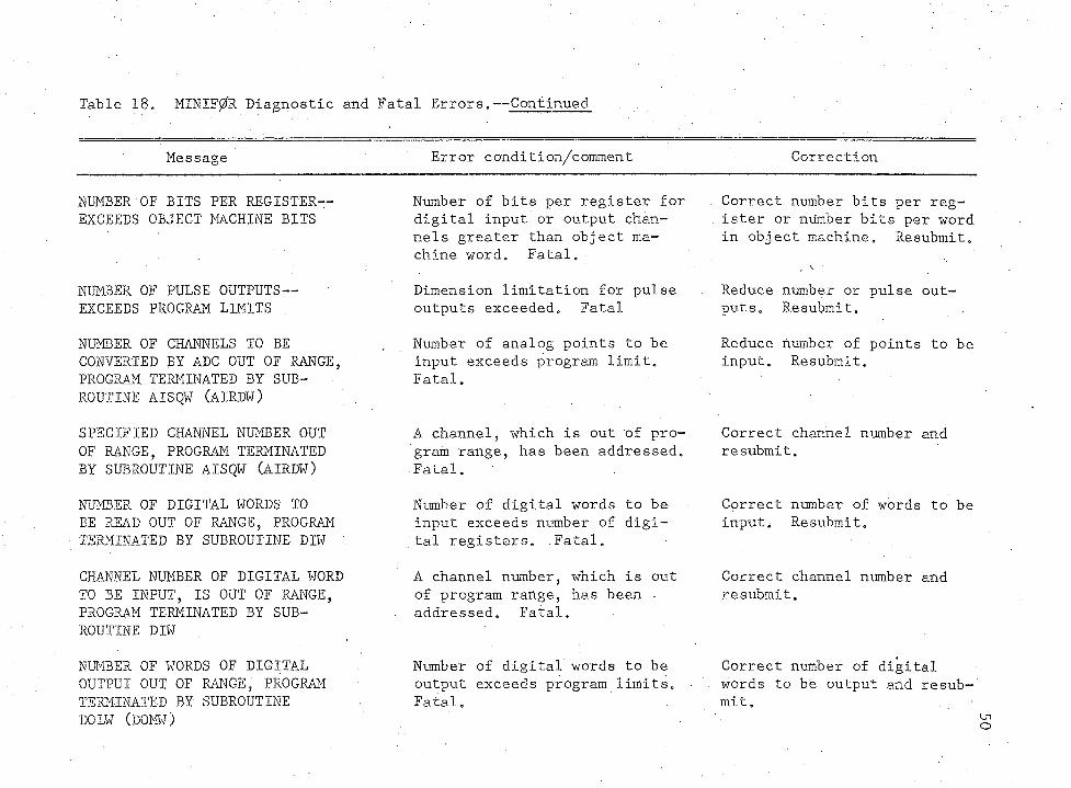
Table 18. MINIF0R Diagnostic and Fatal Errors. -Continued
Message Error condition/comment , Correction
NUMBER OF BITS PER REGISTER— EXCEEDS OBJECT MACHINE BITS
NUMBER OF PULSE OUTPUTS— EXCEEDS PROGRAM LIMITS
NUMBER OF CHANNELS TO BE CONVERTED BY ADC OUT OF RANGE, PROGRAM TERMINATED BY SUB- ROUTINE AISQW (AIRDW)
SPECIFIED CHANNEL NUMBER OUT OF RANGE, PROGRAM TERMINATED BY SUBROUTINE AISQW (AIRDW)
NUMBER OF DIGITAL WORDS TO BE READ OUT OF RANGE, PROGRAM TERMINATED BY SUBROUTINE DIW
CHANNEL NUMBER OF DIGITAL WORD TO BE INPUT, IS OUT OF RANGE, PROGRAM TERMINATED BY SUBROUTINE DIW
NUMBER OF WORDS OF DIGITAL OUTPUT OUT OF RANGE, PROGRAM TERMINATED BY SUBROUTINE DOLW (DOMW)
Number of bits per register for digital input or output channels greater than object machine word. Fatal. •
Dimension limitation for pulse outputs exceeded. Fatal
Number of analog points to be input exceeds program limit. Fatal.
A channel, which is out of program range, has been addressed. Fatal.
Number of digital words to be input exceeds number of digital registers. Fatal.
A channel number, which is out of program range, has been - addressed. Fatal.
Number of digital words to be output exceeds program limits. Fatal.
Correct number bits per register or number bits per word in object machine. Resubmit.
Reduce number or pulse outputs. Resubmit.
Reduce number of points to be input. Resubmit.
Correct channel number and resubmit.
Correct number of words to be input. Resubmit.
Correct channel number and resubmit.
Correct number of digital words to be output and resubmit.
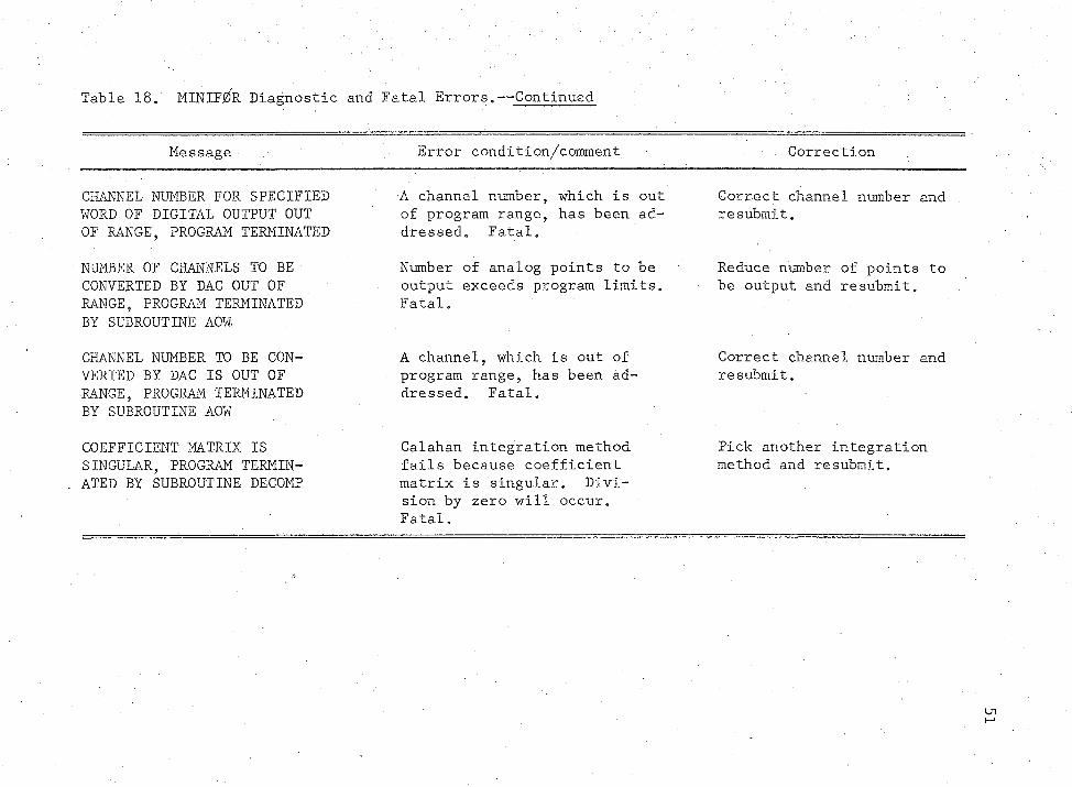
Table 18. HINIF^R Diagnostic and Fatal Errors. — Continued
Message • Error condition/comment. . Correction
CHANNEL NUMBER FOR SPECIFIED WORD OF DIGITAL OUTPUT OUT OF RANGE, PROGRAM TERMINATED
A channel number, which is out of program range, has been addressed. Fatal.
Correct channel number and resubmit.
NUMBER OF CHANNELS TO BE CONVERTED BY DAC OUT OF RANGE, PROGRAM TERMINATED BY SUBROUTINE AOW
Number of analog points to be output exceeds program limits. Fatal.
Reduce number of points to be output and resubmit.
CHANNEL NUMBER TO BE CONVERTED BY DAC IS OUT OF .RANGE, PROGRAM TERMINATED BY SUBROUTINE AOW
A channel, which is out of program range, has been addressed. Fatal.
Correct channel number and resubmit.
COEFFICIENT MATRIX IS SINGULAR, PROGRAM TERMINATED BY SUBROUTINE DECOMP
Calahan integration method fails because coefficient matrix is singular. Division by zero will occur. Fatal.
Pick another integration method and resubmit.
. 52
words or address a channel number out of range, then a fatal error mes
sage is printed and the program is terminated. If the system output
routine is used, then prior to termination the time history is printed.
The implicit Calahan integration method uses a coefficient ma
trix formed from an identity and Jacobian matrix. Division by zero
will occur if the coefficient matrix is. singular. Subroutine DECOMP
aborts the job if this condition exists.
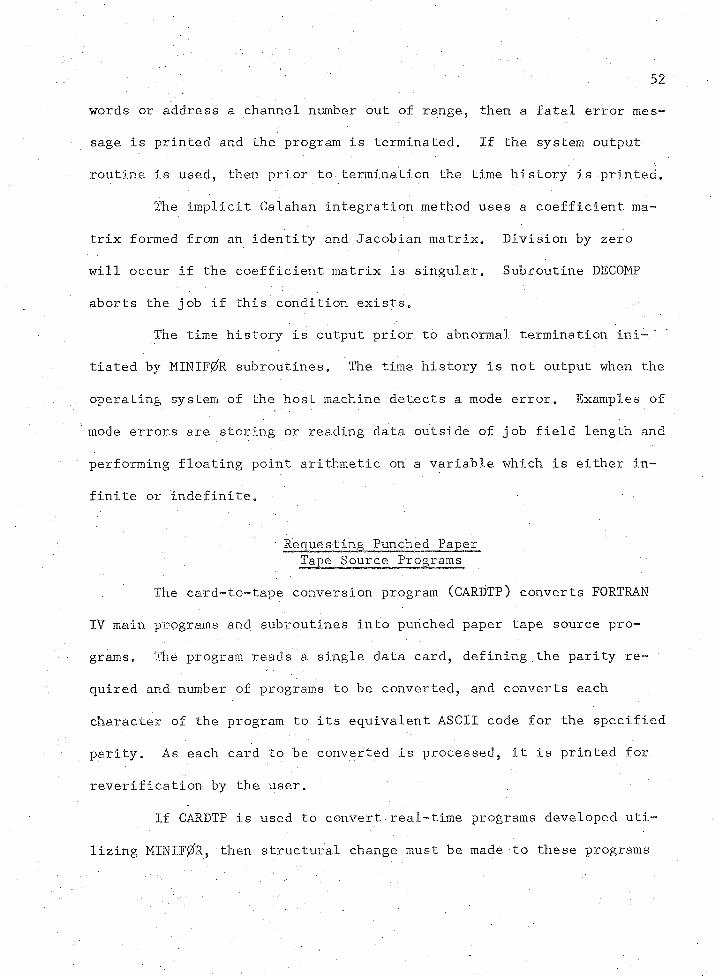
The time history is output prior to abnormal termination ini-"
tiated by MINIF^R subroutines„ The time history is not output when the
operating system, of the host machine detects a mode error. Examples of
mode errors are storing or. reading data outside of job field length and
performing floating point arithmetic on a variable which is either in
finite or indefinite.
Requesting Punched Paper Tape Source Programs
The card-to-tape conversion program (CARDTP) converts FORTRAN
IV main programs and subroutines into punched paper tape source pro
grams. The program reads a single data card, defining.the parity re
quired and number of programs to be converted, and converts each
character of the program to its equivalent ASCII code for the specified
parity. As each card to be converted is processed, it is printed for.
reverification by the user. ,
If CARDTP is used to convert real-time programs developed uti
lizing MINIF0R, then structural change must be made to these programs
53
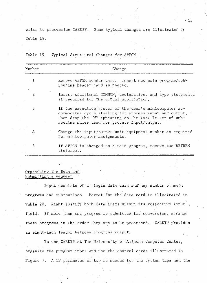
prior to processing CARDTP, Some typical changes are illustrated in
Table 19.
Table 19. Typical Structural Changes for APPGM.:
Number Change
1 Remove APPGM header card. Insert new main program/subroutine header card as needed.
2 Insert additional COMMON? declarative, and type statements if required for the actual application.
3 If the executive system of the user!s minicomputer accommodates cycle stealing for process input and output, then drop the nWf! appearing as the last letter of subroutine names used for process input/output.
4 Change the input/output unit equipment number as required for minicomputer assignments.
5 If APPGM is changed to a main program, remove the RETURN statement.
Organizing the Data and .Submitting a Request
Input consists of a single data card and any number of main
programs and subroutines. Format for the data card is illustrated in
Table 20. Right justify both data items within its respective input
field. If.more than one program is submitted for conversion, arrange
these programs in the order they are to be processed. CARDTP provides
an eight-inch leader between programs output.
To use CARDTP at The University of Arizona Computer Center,
organize the program input and use the control cards illustrated in
Figure 7. A TP parameter of two is needed for the system tape and the
54
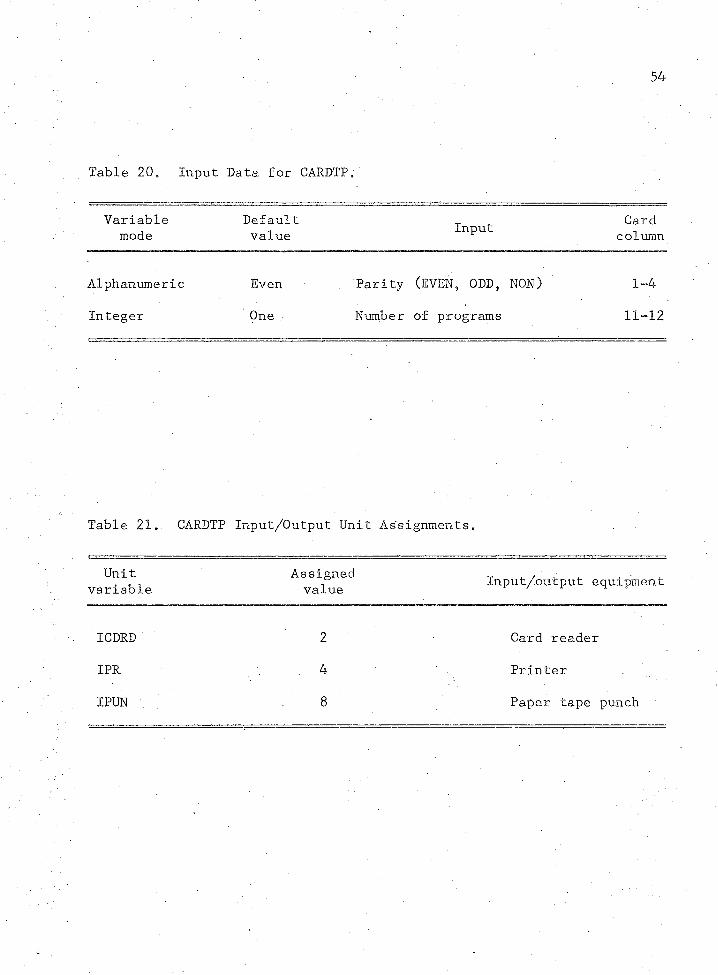
Table 20. Input Data for CARDTP •
Variablemode
Defaultvalue Input Card
column
Alphanumeric Even Parity (EVEN, ODD, NON) 1
Integer One Number of programs 11-12
Table 21. CARDTP Input/Output Unit Assignments„
Unitvariable
Assignedvalue Input/output equipment
ICDRD 2 Card reader
IPR 4 Printer
I PUN 8 Paper tape punch
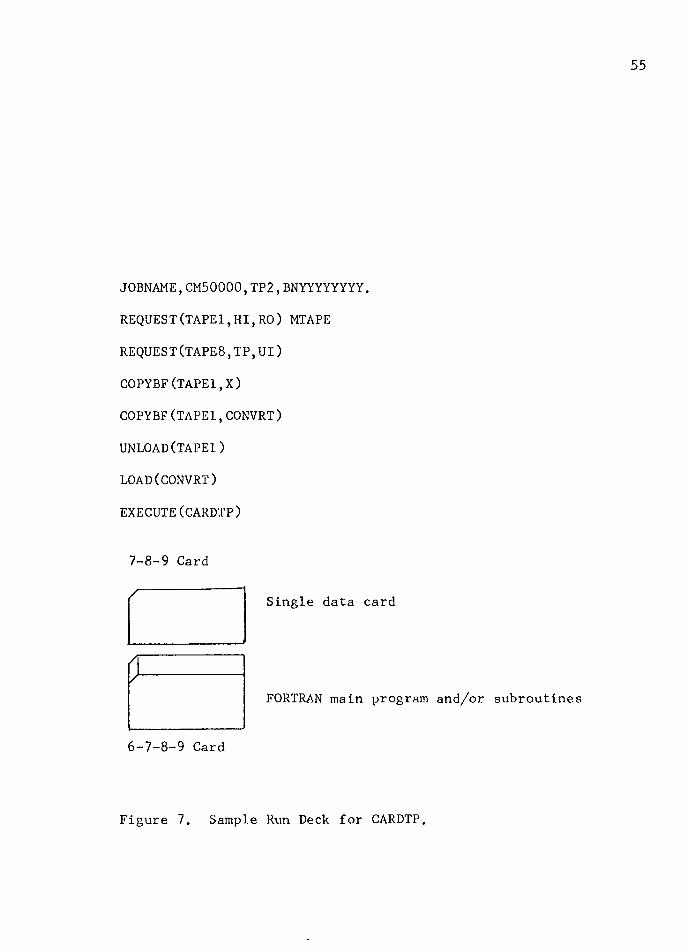
JOBNAME,CM50000,TP2,BNYYYYYYYY.
REQUEST(TAPE1,HI,RO) MTAPE
REQUEST(TAPES,TP,UI)
COPYBF(TAPE1,X)
COPYBF(TAPE1,CONVRT)
UNLOAD(TAPE1)
LOAD(CONVRT)
EXECUTE(CARDTP)
7-8-9 Card
Single data card
y-r
FORTRAN main program and/or subroutines
6-7-8-9 Card
Figure 7. Sample Run Deck for CARDTP.
56
paper tape punch. The system tape number is obtained from the Depart
ment .of Chemical Engineering.
To process CARDTP at other installations organize the program
input as illustrated in Figure 7. Compilation of CARDTP on a CDC 6400
produces object code requiring 16,400g.words. The program does not re
quire temporary storage. Input/output equipment unit numbers are rep
resented by variables. Users at other installations desiring to use
different input/output unit assignments should change the assignments
of the unit variables in the CARDTP executive and change the CARDTP
program header card. The present assignments are summarized in Table
21 (see p. 54).
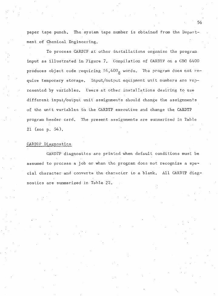
CARDTP Diagnostics
CARDTP diagnostics are printed when default conditions must be
assumed to process a job or when the program does not recognize a spe
cial character and converts the character to a blank. All CARDTP diag
nostics are summarized in Table 22.
57
Table 22. CARDTP Diagnostics,
Message Comment
PARITY NOT SPECIFIED, DEFAULT ASSUMED.
NUMBER OF PROGRAMS NOT SPECIFIED,DEFAULT ASSUMED.
SPECIAL CHARACTER IN COLUMN— NOT RECOGNIZED CHARACTER CONVERTED TO A BLANK.
Conversion parity not specified. Even parity is assumed.
Number of programs to be converted is not specified. CARDTP will convert one program.
A special character not recognizable by CARDTP has been encountered. Conversion is made to a blank. If this character is essential, change CARDTP conversion codes for special characters and resubmit.
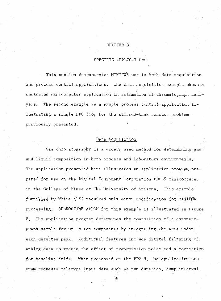
CHAPTER 3
SPECIFIC APPLICATIONS
This section demonstrates MINIF0R use in both data acquisition
and process control applications„ The data acquisition example shows a
dedicated minicomputer application in automation of chromatograph anal
ysis. The second example is a simple process control application il
lustrating a single DDC loop for the stirred-tank reactor problem,
previously presented.
Data Acquisition
Gas chromatography is a widely used method for determining gas
and liquid composition in both process and laboratory environments.
The application presented here illustrates an application program pre
pared for use on the Digital Equipment Corporation PDP-9 minicomputer
in the College of Mines at The University of Arizona. This example
furnished by White (18) required only minor modification for MINIF0R
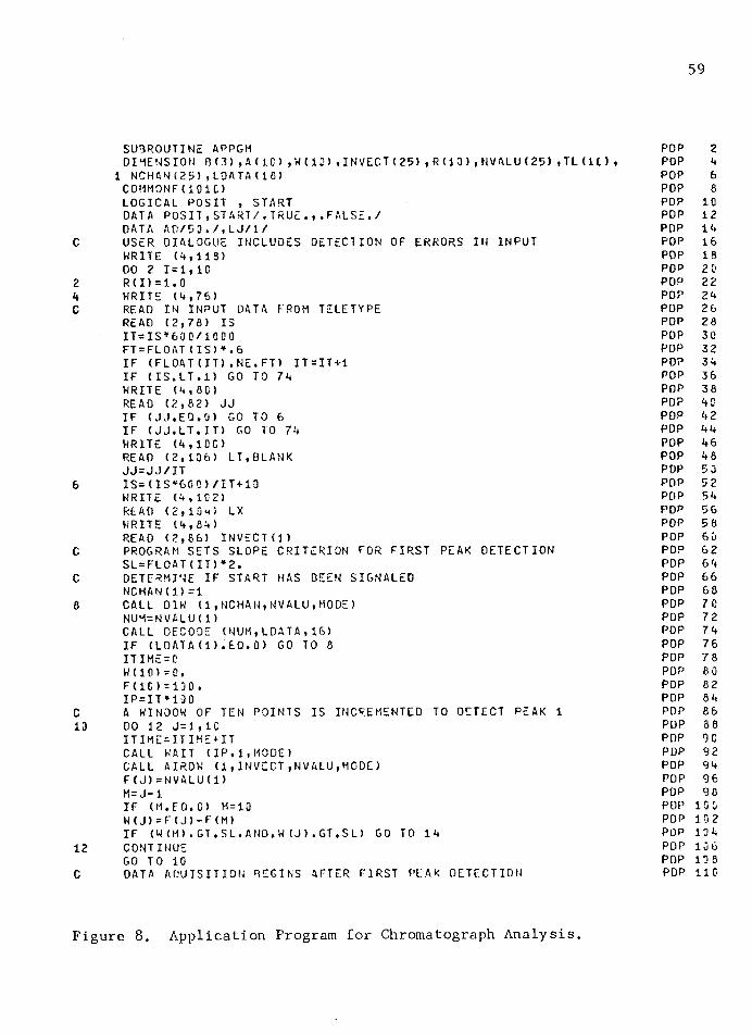
processing. SUBROUTINE APPGM for this example is illustrated in Figure
8. The application program determines the composition of a chromato
graph sample for up to ten components by integrating the area under
each detected peak. Additional features include digital filtering of
analog data to reduce the effect of transmission noise and a correction
for baseline drift. When processed on the PDR-9, the application pro
gram requests teletype input data such as run duration, dump interval,
58
59
SUBROUTINE APPGM POP 2DIMENSION B(3),A(1C),H(13),INVECT(25> , R (13),NVALU(25) ,TL (1C> , POP 4
1 NCHAN(25),LOATA(18) POP 6COHMONF(IOIC) POP 8LOGICAL POSIT , START POP 10DATA POSIT,START/,TRUE.,.FALS E. / POP 12DATA AO/53./,LJ/1/ POP 14
c USER DIALOGUE INCLUDES DETECTION OF ERRORS IN INPUT POP 16WRITE (4,118) POP 18DO 2 1=1,10 POP 2 0
2 R (I) = 1. 0 POP 224 WRITE (4,76) POP 24C READ IN INPUT DATA FROM TELETYPE POP 26
READ (2,76) IS POP 28IT=IS*60 0/1003 POP 3 0FT=FLOAT(IS)*.6 POP 32IF (FLOAT(IT).NE.FT) IT=IT+1 POP 34IF (IS.LT.l) GO TO 74 POP 36WRITE (4,80 POP 38READ (2,62) JJ POP 40IF (JJ.EQ.G) GO TO 6 POP 4 2IF (JJ.LT.IT) GO TO 74 POP 44WRITE (4,100 POP 46READ (2,136) LT,BLANK POP 48JJ=JJ/IT POP 53
6 IS=(IS*60C)/IT+10 POP 52WRITE (4,102) POP 54READ (2,10m ) LX POP 56WRITE (4,84) POP 58READ (2,86) INVECT(I) POP 63
C PROGRAM SETS SLOPE CRITERION FOR FIRST PEAK DETECTION POP 62SL=FLOAT(IT)*2. POP 64
C DETERMINE IF START HAS BEEN SIGNALED POP 6 6NCHAN(l)=1 POP 68
8 CALL D1W (1,NCHAN,NVALU,MODE) POP 70NUM=NVALU(1) POP 72CALL DECODE (MUM,LDATA,16) POP 74IF (LOATA(l).EQ.O) GO TO 8 POP 76ITIME = C POP 78W d O =0. POP 80F(1C)=100 . POP 82IP = IT *10 0 POP 84
C A WINDOW OF TEN POINTS IS INCREME NTED TO DETECT PEAK 1 POP 8613 DO 12 J=1,1C POP 88
ITIME=ITIHE+IT POP 90CALL WAIT (IP,1,MODE) POP 92CALL AIROW (1,INVECT,NVALU,MODE) POP 94F(J)=NVALU(1) POP 96M = J-1 POP 98IF (M.FQ.O M = 10 POP 100W(J)=F(J)-F(M) POP 10 2IF (W(M).GT.SL.AND.W (J).GT.SL) GOi TO 14 POP 134
12 CONTINUE POP 136GO TO 10 POP 136
C DATA ADU IS IT ION BEGINS AFTER FIRST PEAK DETECTION POP 110
Figure 8. Application Program for Chromatograph Analysis.
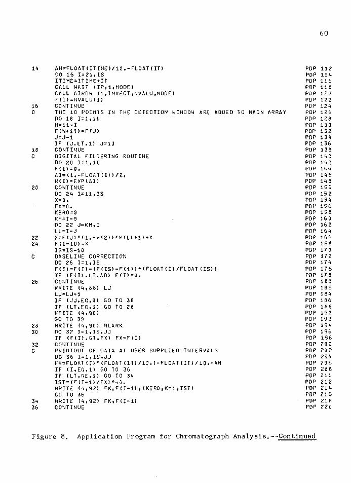
60
14 AM = FL0AT(11IME)/10.-FLOAT(IT) POP 11200 16 1=21,IS POP 114ITIME=ITIME+IT POP 116CALL WAIT (IP,1,MODE) POP 118CALL AIROW <1 ,INVECT ,NVALU,M00E) POP 120F(I)=NVALU(1) POP 122
16 CONTINUE POP 124C THE 10 POINTS IN THE DETECTION WINDOW ARE ADDED TO MAIN ARRAY POP 126
DO 18 1=1,10 POP 126N=11-I POP 133F(N+10)=F(J) POP 132J=J-1 POP 134IF (J.LT.l) J=1J POP 136
18 CONTINUE POP 138C DIGITAL FILTERING ROUTINE POP 14 C
DO 20 1=1,10 POP 142F (I) =0 . POP 144AI=(1,-FLOAT(I))/2. POP 146W(I)=EXP(AI> POP 148
20 CONTINUE POP 15 0DO 24 1=11,IS POP 152X= 0 ♦ POP 154FX = 0. POP 156KERO=0 POP 158KM=I-9 POP 16 0DO 22 J=KM,I POP 162LL=I-J POP 164
22 X=F(J)*(1.-H(2))*H(LL+1)+X POP 16624 F (I-10)=X POP 168
IS=IS-10 POP 170C BASELINE CORRECTION POP 172
DO 26 1=1,IS POP 174F(I)=F(D- (F(IS)-F(l) ) * (FLOAT (I) /FLOAT (IS) ) POP 176IF (F(I).LT.AD) F (I)= 0 » POP 178
26 CONTINUE POP 180WRITE (4,88) LJ POP 182LJ=LJ+1 POP 184IF (JJ.EQ.O) GO TO 38 POP 186IF (LT.EO.l) GO TO 28 POP 188WRITE (4,90) POP 190GO TO 30 POP 192
28 WRITE (4,90) BLANK POP 19430 DO 32 1=1,IS,JJ POP 196
IF (F(I).GT.FX) F X = F (I ) POP 19832 CONTINUE POP 200C PRINTOUT OF DATA AT USER SUPPLIED INTERVALS POP 202
DO 36 1 = 1, IS,JJ POP 20 4FK=FLOAT(I)* (FLOAT(IT)/I:.)-FLOAT(IT)/10.^AM POP 206IF (I.EQ.l) GO TO 36 POP 208IF (LT.NE.l) GO TO 34 POP 210IST = (F (1-1) / FX) POP 212WRITE (4,92) FK,F(I-1),(KERO,K=l, 1ST) POP 214GO TO 36 POP 216
34 WRITE (4,92) FK,F(I-1) POP 21836 CONTINUE POP 220
Figure 8. Application Program for Chromatograph Analysis.— Continued
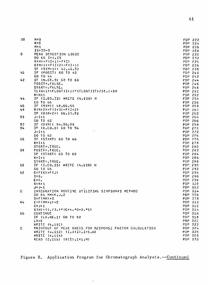
61
38 N= 0 POP 222K=0 POP 224M=1 POP 226IS=IS-3 POP 22 8
C PEAK DETECTION LOGIC POP 230DO 66 1=1,IS POP 232B(M)=F(I+1)-F(D POP 234B(M+l)=F(I+2)-F(I+l) POP 236IF (B(Hf1)) 40,h o ,52 POP 238
40 IF (POSIT) GO TO 42 POP 240GO TO 44 POP 242
42 IF (N.GT.9) GO TO 68 POP 244POSIT=.FALSE. POP 246START=.FALSE. POP 248TL(N+l)=FLOAT(!+!)♦(FLOAT(IT)/1C.)+AM POP 25 0N=N+1 POP 252
44 IF (I.EQ.IS) WRITE (4,108) N POP 254GO TO 66 POP 256
46 IF (B (H)) 48,66,66 POP 25 848 B(M+2)=F(I+3)-F(I+2) POP 26 0
IF (B(M+2)) 66,50,50 POP 26250 J=I + 1 POP 264
GO TO 62 POP 26652 IF (B(M)) 54,56,58 POP 26854 IF (K.EQ.0) GO TO 56 POP 27 C
J=I + 1 POP 272GO TO 62 PUP 274
56 IF (START) GO TO 66 POP 276K=I + 1 POP 278START = ,T RUE• POP 280
58 POSIT = .T RUE. POP 282IF (START) GO TO 60 POP 284K=I+1 POP 286START=.TRUE. POP 288
60 IF (I.EQ.IS) WRITE (4,108) N POP 290GO TO 66 POP 292
62 C=F(K)+F(J) POP 294D=0. POP 296E = 0. POP 296K=K+1 POP 300J=J-1 POP 302
C INTEGRATION ROUTINE UTILIZING SIMPSONZS METHOD POP 304DO 64 MM=K,J,2 POP 306D=F(MM)+D POP 30 8
64 E=F(MM+1)+E POP 310K = J+1 POP 312A(N)=(l./3.)+(C+4.+D+2.*E) POP 314
66 CONTINUE POP 316IF (LX.NE.l) GO TO 68 POP 316LX = C POP 32 CWRITE (4,110 POP 322
C PRINTOUT OF PEAK AREAS FOR RESPONSE FACTOR CALCULATION POP 324WRITE (4,112) (I,A(I),1=1, N) POP 326WRITE (4,114) POP 32 8READ (2,116) (R(I),1=1,N) POP 330
Figure 8. Application Program for Chromatograph Analysis.— Continued
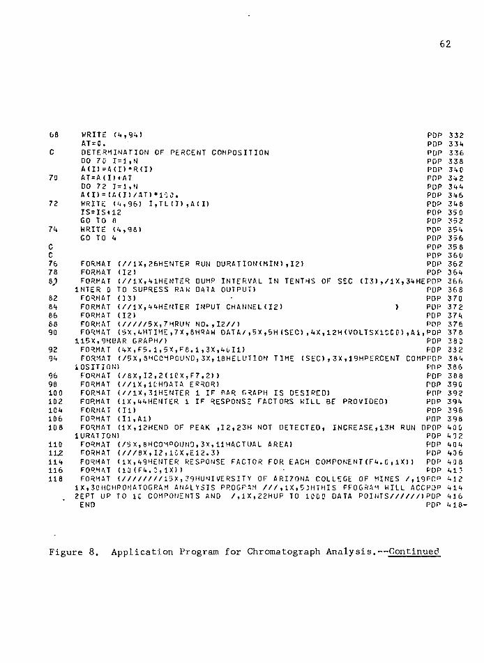
62
68
C
70
72
74CC76788J>8284668890
9294
9698100102104106108
1101L2114116118
WRITE (4,94)AT = C.DETERMINATION DO 70 1=1,N A(I)=A(I)*R(I)AT = A (I),ATDO 7 2 1=1, NA d ) = (A(I) /AT) ♦100.WRITE (4,96) I,TL(I),A(I) IS=IS+12 GO TO 6 WRITE (4,98)GO TO 4
OF PERCENT COMPOSITION
DUMPDATA
INTERVALOUTPUT)
INPUT CHANNEL(12)
FORMAT (//IX,26HENTER RUN DURATION(MIN),12) FORMAT (12)FORMAT (//IX,41HENTER
INTER 0 TO SUPRESS RAW FORMAT (13)FORMAT (//IX,44HENTER FORMAT (12)FORMAT (/////5X,7HRUN FORMAT (5X,4HTIME,7X,8HRAW
119X,9HBAR GRAPH/)FORMAT (4X,F5.1,5X,F8.1,3X,40I1)FORMAT (/5X,8HCOMPOUND,3X,18HELUTION
1 OS IT I ON)FORMAT (/8X,I2,2(1CX,F7.2) )
(//IX, 1C.HOATA ERROR)(//IX,31HENTER 1 IF PAR GRAPH
FORMATFORMATFORMATFORMATFORMATFORMAT
POP POP POP POP POP POP POP POP POP POP POP POP POP POP POP POP POP
(13),/lX,34HEPDP POP POP
) POPPOP
NO.,12//) POPDATA/,5X,5H (SEC) ,4X,12 H (VOLTSX1CC0) ,Ai,PDP
POP POP
TIME (SEC),3X ,19HPERCENT COMPPOPPOP POP POP
IS DESIRED) POP
IN TENTHS OF SEC
(1X,44HENTER 1 IF RESPONSE FACTORS KILL BE PROVIDED) (ID (II,Al)(IX,12HEND OF PEAK ,I2,23H NOT DETECTED,
1URATION)FORMAT (/5X,8HC0MPOUND,3X,11HACTUAL AREA)FORMAT (///8 X ,I2,1CX,E12.3)FORMAT (IX,49HENTER RESPONSE FACTOR FOR EACH FORMAT (13(F4.C,IX))FORMAT (////////15X,79HUNIVERSITY OF ARIZONA
POP POP POP
INCREASE,13H RUN DPDP POP POP POP
COMPONENT(F4.0,IX)) POPPOP
COLLEGE OF MINES /, 19FDPIX,3CHCHPOMATOGRAM ANALYSIS PROGRAM ///,IX,53HTHIS PROGRAM WILL ACCPDP 2EPT UP TO 1C COMPONENTS AND /,1X,22HUP TO ICC D DATA POINTS//////)POP END POP
332 334 336 338 340 342 344 346 348 350 352 354 356 35 8 360 362 364 366 368 370 372 374 376 378 380 332 384 386 388 390 392 394 396 398 40 0 402 404 436 408 410 412 414 416 418-
Figure 8. Application Program for Chromatograph Analysis.— Continued

63
processing options, and ADC channel number on which the chromatograph
signal is input. To process this application program using MINIF^R,
the user dialogue is accomplished by inputting data with the card
reader to simulate teletype input; these data cards are organized and
located immediately after the last MINIF^R input data card as illus
trated in Figure 6„ After the user dialogue is completed, SUBROUTINE
DIW is called to detect a start signal generated by the user when a
chromatograph sample is injected. Once a start signal is detected,
analog inputs are made using.SUBROUTINE AIRDW.
SUBROUTINE MODEL is illustrated in Figure 9. The intensity of,
the chromatograph output is stored as a function of time using a DATA
statement. The first element of IRELAY is used to signal the injection
of a sample (see end of chapter for Figures 9 through 16)..
Coded MINIF^R data forms for this example are illustrated in
Figure 10. All system output is illustrated in Figure 11. Output gen
erated by SUBROUTINE APPGM is illustrated in Figure 12.
Process Control
The process control application consists of a DDC loop for the
stirred-tank reactor problem previously presented in Chapter 2. SUB
ROUTINE APPGM for this application is illustrated in Figure 13. Every
5 seconds the concentration of tank 2 effluent is obtained by issuing a
call to SUBROUTINE APPGM. A position algorithm, SUBROUTINE POSIN (il
lustrated in Figure 14) calculates a new valve position for the manipu
lated variable. The new valve position is then output to a final
control element using SUBROUTINE AOW.
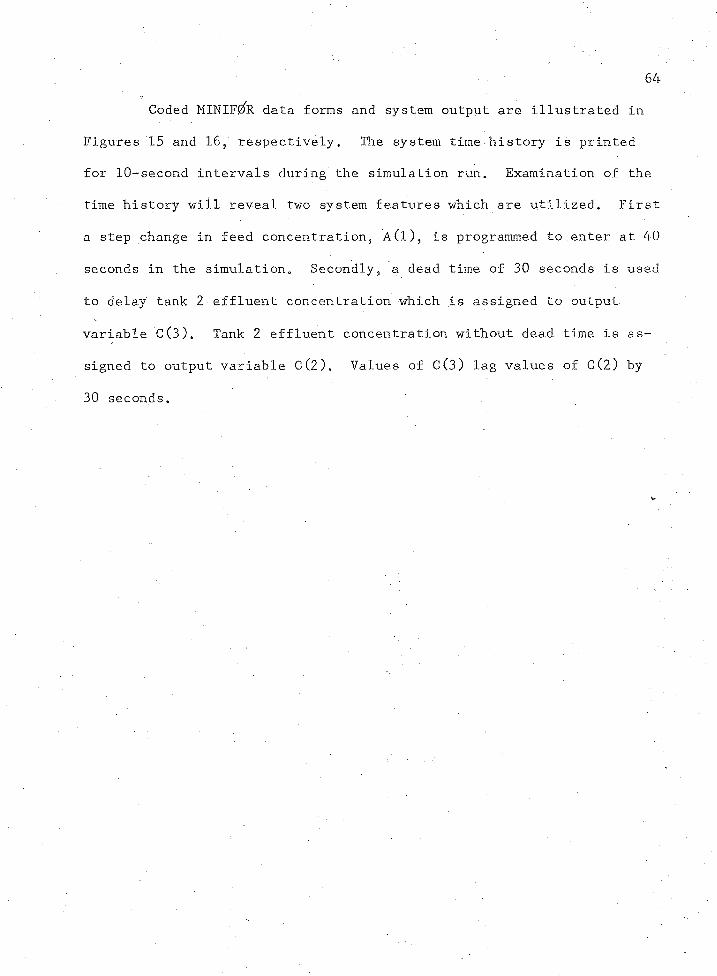
64
Coded MINIF0R data forms and system output are illustrated in
Figures 15 and 16,' respectively. The system time history is printed
for 10-second intervals during the simulation run. Examination of the
time history will reveal two system features which are utilized. First
a step change in feed concentration, A(l), is programmed to enter at 40
seconds in the simulation. Secondly, a dead time of 30 seconds is used
to delay tank 2 effluent concentration which is assigned to output
variable C(3). Tank 2 effluent concentration without dead time is as
signed to output variable C (2). Values of C(3) lag values of C(2) by
30 seconds.
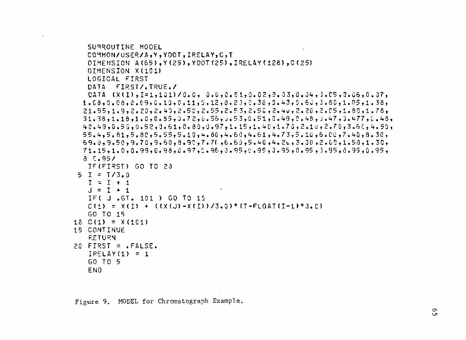
S U B R O U T I N E M O D E LC O M M O N / U S E R / A , Y , Y D O T , I R E L A Y , C , TD I M E N S I O N A ( 6 5 ) , Y ( 2 5 ) , Y D O T ( 2 5 ) , I R E L A Y ( 1 2 8 ) , 0 ( 2 5 )D I M E N S I O N X ( 1 0 1 )L O G I C A L F I R S T D A T A F I R S T / . T R U E . /D A T A ( X ( I ) , 1 = 1 , 1 0 1 ) / O . G , 0 . 0 , 0 . 0 1 , 0 . 0 2 , 0 . j 3 , 0 . u 4 , J . C 5 , D . 0 6 , 0 . 0 7 ,1 . 0 8 . 0 . 0 8 . 0 . 0 9 , 0 . 1 0 , 0 . 1 1 , 0 . 1 2 , 0 . 2 3 , 0 . 3 0 , 0 . 4 3 , 0 . 6 0 , 3 . 8 8 , 1 . 0 5 , 1 . 3 8 ,
2 1 . 5 5 , 1 . 9 , 2 . 2 0 , 2 . 4 0 , 2 . 5 0 , 2 . 5 5 , 2 . 5 3 , 2 . 5 0 , 2 . 4 u , 2 . 2 0 , 2 . 8 5 , 1 . 8 0 , 1 . 7 8 ,3 1 . 3 8 . 1 . 1 8 . 1 . 0 . 0 . 3 5 . 0 . 7 2 , u . 5 5 , j . 5 3 , 0 . 5 1 , 0 . 4 9 , D . 4 8 , 3 . 4 7 , 3 . 4 7 7 , 0 . 4 8 ,4 0 . 4 9 . 0 . 5 0 . 0 . 5 2 . 3 . 6 1 . 0 . 8 0 . 0 . 9 7 . 1 . 1 5 . 1 . 4 0 . 1 . 7 0 . 2 . 1 u , 2 . 7 0 , 3 . 6 0 , 4 . 5 0 , 5 5 . 4 , 5 . 8 1 , 5 . 8 C , 5 . 5 5 , 5 . 1 0 , 4 . 8 0 , 4 , 6 0 , 4 . 6 1 , 4 . 7 3 , 5 . 1 0 , 6 . C U , 7 . 4 0 , 8 . 3 0 ,6 9 . 0 . 9 . 5 0 . 9 . 7 0 . 9 . 6 0 . 9 . 9 0 . 7 . 71. , 6 . 6 0 , 5 . 4 U , 4 . 2 u , 3 . 3 0 , 2 . G O , 1 . 5 0 , 1 . 3 0 ,7 1 . 1 5 . 1 . 0 . 0 . 9 9 , G . 9 8 , G . 9 7 , 0 . 9 6 , 0 . 9 5 , 0 . 9 5 , 0 . 9 5 , 0 . 9 5 , 3 . 9 5 , 0 . 9 5 , 0 . 9 5 ,3 0 . 9 5 /I F ( F I R S T ) G O T O 2 0
5 1 = T / 3 . 0 1 = 1 + 1 J = I + 1I F ( J , G T , 1 0 1 ) G O T O 1 0C ( l ) = X ( I > + ( ( X ( J ) - X ( I ) ) / 3 . 0 ) * ( T - F L O A T ( I - 1 ) * 3 . C )G O T O 1 5
1 0 0 ( 1 ) = X ( 1 G 1 )1 5 C O N T I N U E R E T U R N 2 0 F I R S T = . F A L S E .I R E L A Y ( l ) = 1G O T O 5
E N D
Figure 9. MODEL for Chromatograph Example.O'V I
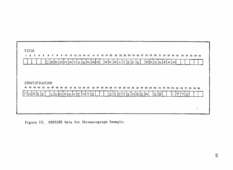
TITLE1 2 3 4 5 6 7 8 9 10 I t 12 13 14 15 16 17 18 19 20 21 22 23 24 25 26 27 28 29 30 31 32 33 34 35 36 37 33 39 40
c R O A T O A- M i l R A tv\
IDENTIFICATION41 42 43 44 45 46 47 48 49 50 51 52 53 54 55 56 57 58 59 60 61 62 63 64 65 66 67 68 69 70 71 72 73 74 75 76 77 78 79 80
H h Ir Ie c O T 5 E r B R 8 ? 7
Figure 10. MINIF0R Data for Chromatograph Example
ChO'-
ITEM VARIABLE NO. MODE INPUT
67
COLUMN
1A INTEGER TOTAL HOURSi
IB INTEGER SIMULATION MINUTES4 5
71C REAL TIME SECONDS b 9 10 11
2A REALFREQUENCY OF PROGRAM 14 15 16 17
OUTPUT, SECONDS
2B ALPHA PRINTOUT ALL INPUT AND 50 21 23
NUMERIC OUTPUT VARIABLES?(YES)
3~ INTEGER NUMBER OF OUTPUT VARIABLES55 56
1
INTEGER NUMBER OF STATE/ ALGEBRAIC VARIABLES
59 504
5 INTEGER NUMBER OF STATE/ALGEBRAIC 33 34
STORED FOR DEAD TIME
6 INTEGER NUMBER OF INPUT VARIABLES37 38
7 INTEGER NUMBER OF INPUT VARIABLES 41 42
STORED FOR DEAD TIME
8 INTEGER NUMBER OF STEP DISTURBANCES 45 46
9 INTEGER NUMBER OF OUTPUT VARIABLES 49 50
MEASURED BY ADC 1
10 INTEGER NUMBER OF INPUT VARIABLES 53 54
MEASURED BY ADC
11 INTEGER NUMBER OF CONTACT SENSORS/ 57 60
ON-OFF DEVICES 1
12A ALPHA INTEGRATION RULE 61 62 63
NUMERIC (RK2, RK4, CAL, BUM) D u m |12B REAL INTEGRATION STEP SIZE, SECONDS
66 67 68 69
I]Figure 10. MINIF0R Data for Chromatograph Example.— Continued
I
ITEM VARIABLENO. MODE INPUT COLUMN
OBJECT MACHINE
NUMBER BITS PER WORD1A INTEGER
BASIC SYSTEM CLOCK COUNT MILLISECONDSIB REAL
ANA LOG-TO-DIGITAL CONVERTER
ADC SCALE FACTOR, HARDWARE UNITSREAL
DIGITAL INPUT29 30
NUMBER OF DIGITAL INPUTSINTEGER33 34
NUMBER BITS PER REGISTER3B INTEGER
DIGITAL-TO-ANALOG CONVERTER37 33
4A NUMBER OF CHANNELS UTILIZEDINTEGER
4B REAI DAC SCALE FACTOR, HARDWARE UNITS
LATCHING DIGITAL OUTPUT49 50
NUMBER DIGITAL OUTPUTSINTEGER53 54
NUMBER BITS PER REGISTERINTEGER
MOMENTARY DIGITAL OUTPUT57 58
6A NUMBER BITS PER REGISTERINTEGER
6B NUMBER PULSE OUTPUTSINTEGER
6C INTEGER NUMBER PULSES PER CLOCK COUNT
Figure 10. MINIF0R Data for Chromatograph Example.— Continued
69
CONTACT SENSOR/ ON-OFF DEVICE COLUMN
RELAYS 1-16
RELAYS 17-32
RELAYS 33-48
1 2 3 4 5 6 7 8 9 10 11 12 13 14 15 16
17 18 19 20 21 22 23 24 25 26 27 28 29 30 31 32
33 34 35 36 37 38 39 40 41 42 43 44 45 46 47 48
RELAYS 49-6449 50 51 52 53 54 55 56 57 58 59 60 61 62 63 64
Figure 10. MINIF0R Data for Chromatograph Example.— Continued
PROCESS SPECIFICATIONS HARDWARE SPECIFICATIONS
I"-OUTPUT VARIABLE MEASURED SAMPLED ON CHAWEL — 1r ENG. MINIMUM MAXIMUM SIGNAL READ BY ADC FOR DESIGNATED LEVEL OF MEASURAND, HARDWARE UNITS ]c UNITS MEASURAND MEASURAND0 1 10 1 30 1 50 1 70 I 90 1 100 NO.
; i°if P.72 n U K ?t 77 28 ?9 30 31 3? 33 34 35 36 37 38 39 40 41 *2 <3 *4 45 46 *7 48 49 50 31 S? S3 54 55 56 37 31 39 60 6 1 6? 63 64 65 66 67 66 70 71 72
1 U
' I
I I
i I i !
1 2 3 4 S 6 7 8 9 >0 II 12 13 >4 15 16 t7 18 19 20 21 22 23 24 2S 26 27 28 29 » 31 32 33 34 33 36 37 38 39 40 41 42 43 44 45 46 47 48 49 SO 51 52 S3 54 S5 56 57 S8 5? 60 61 6? 63 64 6S 66 67 68 69 TQ 71 7? 73 74 75 76 77 7| 79 80
73 74 75 76 77 79 79 ac
1 5. 0!
F i g u r e 1 0 . M I N I F 0 R D a t a f o r C h r o m a t o g r a p h E x a m p l e . — C o n t i n u e d
o
V E R S I O NM I N I F O R
1 S E P T E M B E R 2 5 , 1 9 7 2 * * * * * * * * * * * * *
A N A L Y S I S O F S I M U L A T I O N A N D H A R D W A R E S P E C I F I C A T I O N S F R O M I N P U T C A R D S 1 - 3T I T L E - C H R O M A T O G R A M A N A L Y S I S P R O G R A MI D E N T I F I C A T I O N - T H R E E C O M P O N E N T S , S E P T E M B E R 28, 1 9 7 2S P E C I F I C A T I O N S F O R S I M U L A T E D E N V I R O N M E N T E R R O R C O N D l i l O N ' / C O M M E N T
T Y P E S I M U L A T I O N A L G E B R A I C M O D E LS I M U L A T I O N T I M E -0 H O U R S , 7 M I N U T E S , - 0 . 0 0 S E C O N D SF R E Q U E N C Y O F M I N I F O R O U T P U T , S E C O N D S 1 . C 3N U M B E R O F O U T P U T V A R I A B L E S 1N U M B E R O F I N P U T V A R I A B L E S -0N U M B E R O F I N P U T V A R I A B L E S D E L A Y E D - 0N U M B E R O F S T A T E / A L G E B R A I C V A R I A B L E S -0N U M B E R O F S T A T E / A L G E B R A I C V A R I A B L E S D E L A Y E D ' -0N U M B E R O F D I S T U R B A N C E S -0N U M B E R O F C O N T A C T S E N S O R S / O N - O F F D E V I C E S 1
S P E C I F I C A T I O N S F O P O B J E C T M A C H I N E A N D I / O H A R D W A R EO B J E C T M A C H I N E
N U M B E R O F B I T S P E R W O R D C L O C K C O U N T , M I L L I S E C O N D S
181 6 . 6 7 0
A N A L O G T O D I G I T A L C O N V E R T E R N U M B E R O F C H A N N E L S U T I L I Z E D S C A L E F A C T O R , H A R D W A R E U N I T S
11000.0 N O T S P E C I F I E D
D I G I T A L i n p u tN U M B E R O F D I G I T A L I N P U T S N U M B E R O F B I T S P E R R E G I S T E R N U M B E R O F R E G I S T E R S
D I G I T A L T O A N A L O G C O N V E R T E R N U M B E R O F C H A N N E L S U T I L I Z E D
1161
-0
N O T S P E C I F I E D
D I G I T A L O U T P U T N O T U T I L I Z E D
P U L S E O U T P U T SN U M B E R O F P U L S E O U T P U T S -0
N O F A T A L E R R O R S F O U N D
F i g u r e 1 1 . M I N I F O R O u t p u t f o r C h r o m a t o g r a p h E x a m p l e .
S E V E R I T Y
D E F A U L T A S S U M E D
D E F A U L T A S S U M E D

C H R O M A T O G R A M A N A L Y S I S P R O G R A MT H R E E C O M P O N E N T S , S E P T E M B E R 2 8 , 1 9 7 2
P R O G R A M E X P E C T S F O L L O W I N G C A R O I N V E N T O R YC A R D ( S ) F O R S P E C I F I E D I N P U T N U M B E R O F C A R O S
0 0 1 0 0 G 0 1 G C 0
Figure 11. MINIF0R Output for Chromatograph Example.— Continued
I N P U T V A R I A B L E S N O T P U L S E DS T A T E / A L G E B R A I C V A R I A B L E SN U M B E R O F D I G I T A L I N P U T SN U M B E R O F D I G I T A L O U T P U T SD I S T U R B A N C E SI N P U T V A R I A B L E S D E L A Y E DS T A T E / A L G E B R A I C V A R I A B L E S D E L A Y E DO U T P U T V A R I A B L E S T O B E M E A S U R E D B Y A D CI N P U T V A R I A B L E S T O B E M E A S U R E D B Y A D CI N P U T V A R I A B L E S T O B E . M A N I P U L A T E D B Y O A C ,I N P U T V A R I A B L E S T O B E M A N I P U L A T E D B Y P U L S E S
C H R O M A T O G R A M A N A L Y S I S P R O G R A MT H R E E C O M P O N E N T S , S E P T E M B E R 2 8 , 1 9 7 2
D I G I T A L I N P U T P O S I T I O NI R E L A Y C 1 ) C L O S E D
Figure 11. MINIF0R Output for Chromatograph Example.— Continued
C H R O M A T O G R A M A N A L Y S I S P R O G R A M T H R E E C O M P O N E N T S , S E P T E M B E R 2 8 , 1 9 7 2
S P E C I F I E D P R O C E S S / M O D E L O U T P U T V A R I A B L E S T O BE M E A S U R E D BY A N A L O G T O D I G I T A L C O N V E R T E RP R O C E S S S P E C I F I C A T I O N S A N A L O G S I G N A L T O A D C F O R D E S I G N A T E D L E V E L O F M E A S U R A N O , H O W E U N I T Sa**********#*****.******************* $**+*******»***$+****************#»******$***$***#$*$*********#*****
V A R I A B L E M I N I M U M M A X I M U M C 10 33 50 70 90 ICCM E A S U R E D U N I T S M E A S U R A N O M E A S U R A N O P E R C E N T P E R C E N T P E R C E N T P E R C E N T P E R C E N T P E R C E N T P E R C E N TC( 1) I N T N 0 . 0 0 1 0 . 0 0 0 . 0 0 1 . C 0 3 . 0 5 5 . 3 0 7 . 0 0 9 . 0 0 1 0 . 5 0
S A M P L E D O N C H A N N E L13
Figure 11. MINIF0R Output for Chromatograph Example.— Continued
75
U N I V E R S I T Y O F A R I Z O N A C O L L E G E O F M I N E S C H R O M A T O G R A M A N A L Y S I S P R O G R A M
T H I S P R O G R A M W I L L A C C E P T U P T O 1 0 C O M P O N E N T S A N D U P T O 1 0 0 u D A T A P O I N T S
E N T E R R U N D U R A T I O N ( M I N ) , I 2
E N T E R D U M P I N T E R V A L I N T E N T H S OF S E C ( 1 3 ) E N T E R U T O S U P R E S S R A W D A T A O U T P U T
E N T E R 1 I F A A R G R A P H I S D E S I R E DE N T E R 1 I F R E S P O N S E F A C T O R S W I L L O E P R O V I D E D
E N T E R I N P U T C H A N N E L ( 1 2 )
Figure 12. User Output for Chromatograph Example.
76
R U N N O . 1
T I M E R A W D A T A( S E C ) ( V O L T S X i Q C O ) B A R G R A P H4 2 . 6 1 1 6 . 5 04 5 . 6 1 8 5 . 0 04 6 . 6 2 7 7 . 0 05 1 . 6 3 9 9 . 3 05 4 . 6 5 5 9 . 8 0 05 7 . 6 7 5 2 . 6 0 0 06 0 . 6 9 9 7 . 2 0 0 0 36 3 . 6 1 2 9 5 . 1 0 0 0 0 06 6 . 6 1 4 8 1 . 1 0 0 0 3 0 06 9 . 6 1 3 0 5 . 1 0 0 0 0 0 0 u 07 2 . 6 2 0 8 5 . 9 0 0 C 0 0 0 G G 07 5 . 6 2 2 6 9 . 9 a o c o o o o o o u7 8 . 6 2 3 5 9 . 7 3 0 0 0 0 0 0 9 0 08 1 . 6 2 3 9 5 . 9 3 0 0 0 0 0 -3 C 0 08 4 . 6 2 3 6 9 . 5 o n c c o n o o o o8 7 . 6 2 3 2 3 . 6 3 0 0 0 0 0 0 0 0 09 ? . 6 2 2 0 3 . 1 3 0 0 0 0 0 3 0 09 3 . 6 2 0 1 0 . 2 3 0 0 3 G C 0 C9 6 . 6 1 8 3 9 . 0 0 C 0 Q 0 Q C C9 9 . 6 1 6 0 9 . 9 0 0 0 0 0 0 31 0 2 . 6 1 5 3 0 . 0 3 0 G 0 0 C1 0 5 . 6 1 1 6 2 . 9 3 0 0 0 01 0 8 . 6 9 4 6 . 8 0 0 0 01 1 1 . 6 7 6 0 . 7 0 0 01 1 4 . 6 6 0 2 . 8 3 01 1 7 . 6 4 6 0 . 2 0 01 2 0 . 6 3 0 6 . 7 Cl1 2 3 . 6 2 6 2 . 0 01 2 6 . 6 2 3 2 . 2 01 2 9 . 6 2 0 3 . 9 31 3 2 . 6 1 8 4 . 0 31 3 5 . 6 1 6 6 . 1 , 01 3 8 . 6 1 6 2 . 1 01 4 1 . 6 1 5 6 . 3 01 4 4 . 6 1 5 6 . 3 31 4 7 , 6 1 5 7 . 8 3
Figure 12. User Output for Chromatograph Example.— Continued
77
1 5 0 . 6 1 7 5 . 0 01 5 3 . 6 2 6 1 . 7 01 5 6 . 6 4 3 3 . 9 01 5 9 . 6 595.3 301 6 2 . 6 7 7 1 . 4 I C O1 6 5 . 6 1011.9 3 C O G1 6 6 . 6 1 3 0 8 . 2 0 G G O G1 7 1 . 6 1 7 1 1 . 5 3000000174.6 2 3 1 3 . 8 3 0 0 0 0 0 0 G O O1 7 7 . 6 3 1 8 8 . 2 3 0 C 0 0 0 3 0 0 0 0 0 0 01 8 C . 6 4 0 7 2 . 7 Q O G O C G I U O C O O G C G O O O1 8 3 . 6 4 9 0 7 . 1 000500 3 0 03000 0 0 0 0 0 30 01 8 6 . 6 5287.3 O O G G O u G O O O C O G C u Q D O O C O O O1 8 9 . 6 5264.5 0 C G 0 C 0 0 C 0 0 0 0 3 0 0 0 0 J 3 L G G 31 9 2 . 6 4 9 9 8 . 3 1 0 G 3 C 0 3 0 G G 0 C 0 0 0 0 3 0 0 G O O1 9 5 . 6 4 5 6 7 . 3 O O C O G O O C u O O C O C G G Q O O O1 9 8 , 6 4262.6 n O G O G O O C O O G O G O G G O O201.6 4 0 7 0 . 4 G C G O J 0 0 C 0 G 0 D 3 G 0 C C G2 0 4 . 6 4 0 7 1 . 3 0 0 0 0 C G 0 G 0 0 0 0 0 0 G 0 >3 G207.6 4 2 0 1 . 2 O C G n O D O C C O C G O C O G C O210.6 4 6 0 1 . 1 0 0 0 0 0 0 3 0 3 0 0 0 0 0 3 0 0 0 3 02 1 3 . 6 5 5 1 0 . 2 0 C C 3 0 C u 0 3 G 0 0 0 0 G G 0 0 C C 0 O u 02 1 6 . 6 6 8 1 4 . 9 3 G C 0 0 O O r G G O G G G Q Q 0 3 3 0 0 0 0 0 0219.6 7 7 0 4 . 1 0 0 0 G 0 0 0 0 0 0 0 0 C G 0 U 0 0 0 0 0 G 0 0 0222.6 8 3 7 9 . 5 O C ' O G G C O C O O O C O u G C O G G G O O a C u225.6 8 8 4 6 . 0 O C G O G O 0 0 0 0 0 0 0 0 0 0 0 0 0 C J 0 3 0 32 2 8 . 6 9 0 2 3 . 1 0 0 C 0 0 0 0 0 0 u 0 C 3 0 C G 0 3 3 0 0 D 0 0 02 3 1 . 6 8 8 6 5 . 3 aeooooseoGOGOOoooaocoooco2 3 4 . 6 8139.5 Q G C 3 0 0 3 C 0 0 0 0 0 0 0 0 0 0 0 0 0 0 0 0 32 3 7 . 6 6973.3 O O C 3 G G O C a C D C O O C G G O Q G 0 3 0 3 02 4 C . 6 5856.2 0 0 0 0 G 0 3 C 0 0 0 3 0 0 0 0 0 0 3 0 0 0 0 0 32 4 3 . 6 4659.9 a O G O O G O C O G O C G O C O O D O O2 4 6 . 6 3 4 5 3 . 6 occocooojoooaoo2 4 9 . 6 2277.7 3 C 0 0 G Q 0 C 0 02 5 2 . 6 1 2 9 5 . 9 Q 0 G O O255.6 806 .7 ODD2 5 8 . 6 592.4 3 0261.6 4 3 1 . 9 3264.6 2 9 1 . 0 02 6 7 . 6 2 6 5 . 4 02 7 0 . 6 2 4 6 . 1 02 7 3 . 6 226.7 02 7 6 . 6 2 0 7 . 4 32 7 9 . 6 1 8 9 . 0 0
000
OvC
3 O G 0 G G C 0 0 J O O O Q 3 0 0 0 0 C C 3 0 3 0 0 0 QGOGOOOGGG O G u G
Figure 12. User Output for Chromatograph Example.— Continued
C O M P O U N D A C T U A L A R E A
1 .3656+36
2 . 5 G 2 E + 0 6
3 . 1 0 4 5 + 0 7E N T E R R E S P O N S E F A C T O R F O R E A C H C O M P O N E N T ( F 4 . 0 , I X )C O M P O U N D E L U T I O N T I M E ( S E C ) P E R C E N T C O M P O S I T I O N
1 8 1 . 3 0 2 0 . 9 52 1 8 7 . 5 0 2 7 . 7 83 2 2 8 . 6 0 . 5 1 . 2 7
Figure 12. User Output for Chromatograph Example.— Continued
S U B R O U T I N E A P P G MD I M E N S I O N I D A T A ( 2 5 ) , L D A T A ( 1 8 ) , N C H A N ( 2 5 ) S E T C O U N T E R F O R C O N C E N T R A T I O N K C O N C = 5C A L L W A I T ( K C O N C , 2 , M O D E )O B T A I N C O N C E N T R A T I O N O F T A N K 2 E F F L U E N T C A L L A I S Q W ( 1 , 2 0 , I O A T A , M O D E )C O N V E R T V O L T S M C O O T O E N G I N E E R I N G U N I T S C V A R = 0 . 0 1 + 0 . O O G 4 * F L O A T ( I D A T A ( i > ) / 1 G 0 C C A L C U L A T E N E W V A L V E P O S I T I O N C A L L P O S I N ( C V A R , V A L P O S )C O N V E R T V A L V E P O S I T I O N T O V O L T S M G u O . I O A T A ( 1 ) = V A L P O S * ! J G O .O U T P U T N E W V A L V E P O S I T I O N N C H A N ( 1 ) = 8C A L L A O W ( l , N C H A N , I O A T A , M O D E )G O T O 5 E N D
Figure 13. Application Program for Stirred-Tank Reactor
80
S U B R O U T I N E P O S I N ( C V A R , V A L P O S )D I M E N S I O N E R R 0 R ( 4 )D A T A X K C , T I , T O , X M I D / 1 2 0 . 0 , 0 . 1 , 1 0 . 0 , 7 2 . 0 /D A T A S E T P T , S A M I N T , S U M , N O I N T / C . 0 2 4 4 , 5 . 0 , 0 . 0 , 0 /N O I N T = N O I N T + 1 E R R O R ( 4 ) = S E T P T - C V A P I F ( N O I N T . G T . 4 ) G O T O 7 D E L = 0 . 0 G O T O 97 D E L = ( E R R O R ( 4 ) - E R R O R ( l ) + 3 . G * E R R O R ( 3 ) - 3 • J * E R R O R ( 2 ) ) / 1 ( 6 . 0 + S A M I N T )9 S U M = S U M + E R R O R ( 4 )V A L P O S = X M I D 4 X K C * ( E R R O R ( 4 ) + S U M / T I + T D * D E L )D O 1 0 1 = 1 , 3 K = 5 - I L = 4 - I 1 0 E R R O R ( L ) = E R R O R ( K )R E T U R NE N D
Figure 14. A Position Algorithm for DDC.
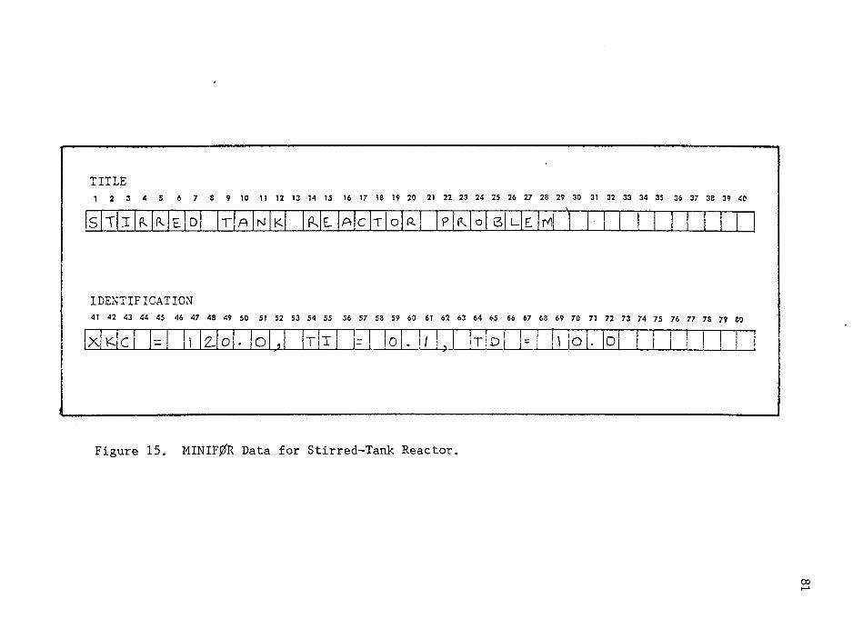
TITLE1 2 3 4 5 6 7 8 9 10 11 12 13 14 15 16 17 18 19 20 21 22 23 24 25 26 27 28 29 30 31 32 33 34 35 36 37 38 39 40
S L T I P. D T A N K L A C T O P. S L rv)
IDENTIFICATION41 42 43 44 45 46 47 48 49 50 51 52 53 54 55 56 57 53 59 60 61 62 63 64 65 66 67 63 69 70 71 72 73 74 75 76 77 78 79 60
X — !i 2- O * o 7 yjx 1 I |f 1 lo . 1/ L !t Id | !=! h lo . °i ...L.l. ! ! i
Figure 15. MINIF0R Data for Stirred-Tank Reactor.
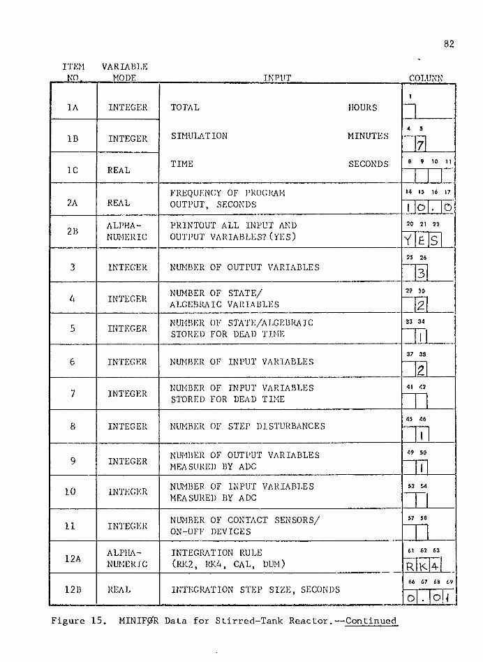
82
ITEM VARIABLENO. MODE_____________________ INPUT____________________COLUMN
1A INTEGER TOTAL HOURSi
IB INTEGER SIMULATION MINUTES« 5
7
1C REAL TIME SECONDS 8 9 10 11
2A REALFREQUENCY OF PROGRAM 14 15 16 17
OUTPUT, SECONDS1 O . o
2B ALPHA PRINTOUT ALL INPUT AND 20 21 22
NUMERIC OUTPUT VARIABLES?(YES) Y £ S
INTEGER NUMBER OF OUTPUT VARIABLES25 26
3 3
INTEGER NUMBER OF STATE/ ALGEBRAIC VARIABLES
29 304 2r: INTEGER NUMBER OF STATE/ALGEBRAIC 33 34 1J STORED FOR DEAD TIME
1 1
6 INTEGER NUMBER OF INPUT VARIABLES
—h
7 INTEGER NUMBER OF INPUT VARIABLES 41 42
STORED FOR DEAD TIME
8 INTEGER NUMBER OF STEP DISTURBANCES 45 46
I
9 INTEGER NUMBER OF OUTPUT VARIABLES 49 50
MEASURED BY ADC 1
10 INTEGER NUMBER OF INPUT VARIABLES 53 54
MEASURED BY ADC
11 INTEGER NUMBER OF CONTACT SENSORS/ 57 58
ON-OFF DEVICES
12A ALPHA INTEGRATION RULE 61 62 63
NUMERIC (RK2, RK4, CAL, DUM) R
12B REAL INTEGRATION STEP SIZE, SECONDS66 67 68 69
O . O
Figure 15. MINIF^R Data for Stirred-Tank Reactor.— Continued
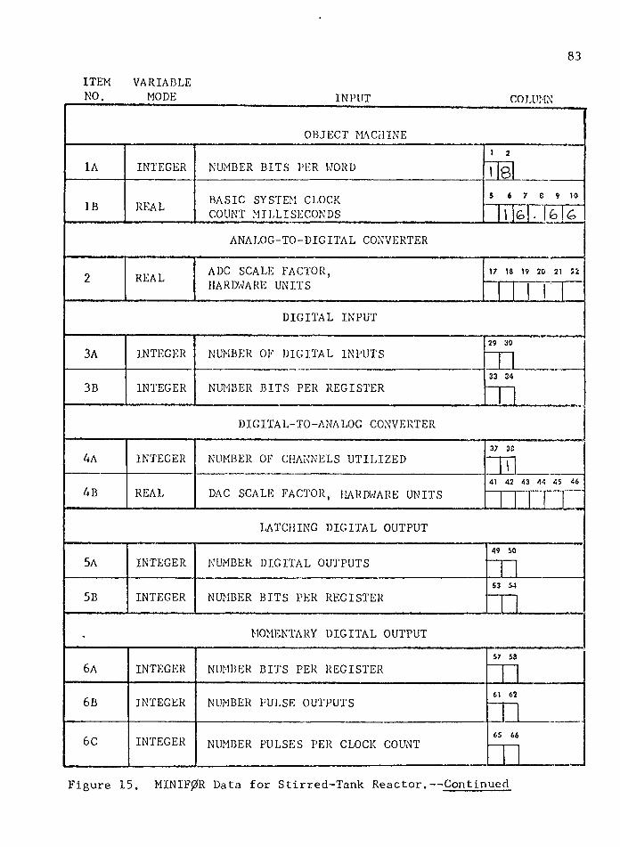
83ITEM VARIABLENO._____ MODE_____________ INPUT COLUMN
OBJECT MACHINEi 2
1A INTEGER NUMBER BITS PER WORD I8IB REAL BASIC SYSTEM CLOCK 5 6 7 8 9 10
COUNT MILLISECONDS 1 G b &
ANALOG-TO-DIGITAL CONVERTER
2 REAL ADC SCALE FACTOR, 17 18 19 20 21 22
HARDWARE UNITS
DIGITAL INPUT
3A INTEGER NUMBER OF DIGITAL INPUTS29 30
3B INTEGER NUMBER BITS PER REGISTER33 34
DIGITAL-TO-ANALOG CONVERTER
4A INTEGER NUMBER OF CHANNELS UTILIZED37 38
“Til4B REAL DAC SCALE FACTOR, HARDWARE UNITS
41 42 43 44 45 46
LATCHING DIGITAL OUTPUT
5A INTEGER NUMBER DIGITAL OUTPUTS49 50
5B INTEGER NUMBER BITS PER REGISTER53 54
• MOMENTARY DIGITAL OUTPUT
6A INTEGER NUMBER BITS PER REGISTER57 58
6B INTEGER NUMBER PULSE OUTPUTS 61 62
6C INTEGER NUMBER PULSES PER CLOCK COUNT 65 66
Figure 15. MINIF0R Data for Stirred-Tank Reactor.— Continued
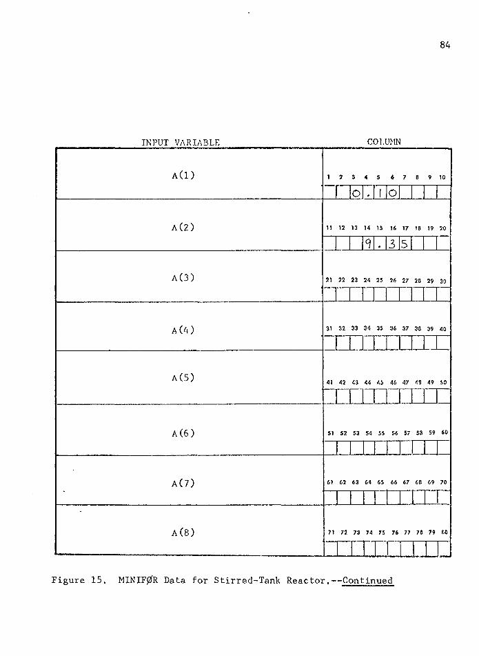
84
INPUT VARIABLE COLUMN
A(l)
A(2)
1 2 5 4 3 6 7 8 9 10
O . I O
11 12 13 14 15 16 17 18 19 20
9 . 3 5
A(3) 21 22 23 24 25 26 27 20 29 30
A (4 ) 31 32 33 34 35 36 37 30 39 40
A(5) 41 42 43 44 45 46 47 43 49 SO
A (6 ) 51 52 53 54 55 56 57 53 59 60
A(7) 61 62 63 64 65 66 67 68 69 70
A(8) 71 72 73 74 75 76 77 76 79 60
Figure 15. MINIF0R Data for Stirred-Tank Reactor.— Continued
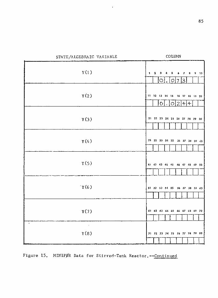
85
STATE/ALGEBRAIC VARIABLE COLUMN
Y (l)
Y(2)
Y(3)
1 2 3 4 5 6 7 8 9 10
o o 7 3
11 12 13 14 15 16 17 18 19 20
0 . 0 2 4 - 4 -
21 27. 23 24 25 26 27 28 29 30
Y(4) 31 32 33 34 35 36 37 38 39 40
Y(5)
Y (6 )
41 42 43 44 45 46 47 46 49 50
i n51 52 53 54 55 56 57 58 59 60
Y(7)
Y(8)
61 62 63 64 65 66 67 63 69 70
71 72 73 74 75 76 77 75 79 60
Figure 15. MINIF0R Data for Stirred-Tank Reactor.— Continued
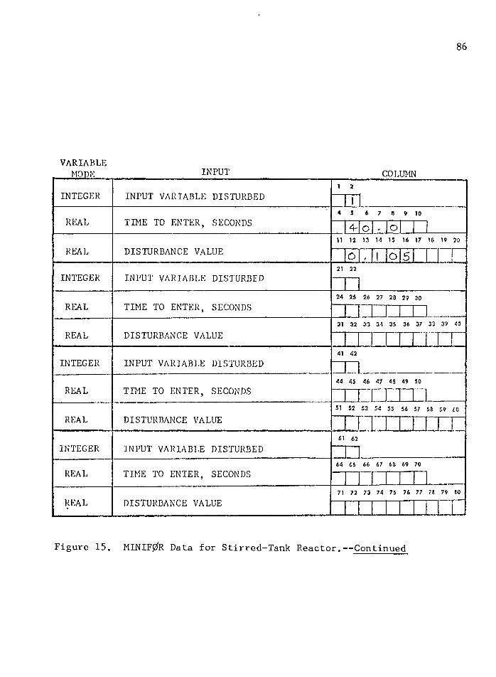
8 6
VARIABLEMODE INPUT COLUMN
I N T E G E R I N P U T V A R I A B L E D I S T U R B E D
i 2
1
R E A L T I M E T O E N T E R , S E C O N D S
4 5 6 7 6 9 104- O , O
R E A L D I S T U R B A N C E V A L U E
11 12 13 14 15 16 17 16 19 20
O , 1 o 5 1
IN T E G E R I N P U T V A R I A B L E D I S T U R B E D
21 22
R E A L T I M E T O E N T E R , S E C O N D S
24 25 26 27 20 29 30
R E A L D I S T U R B A N C E V A L U E
31 32 33 34 35 36 37 33 39 40
I N T E G E R I N P U T V A R I A B L E D I S T U R B E D
41 42
R E A L T I M E T O E N T E R , S E C O N D S
44 45 46 47 48 49 50
R E A L D I S T U R B A N C E V A L U E
51 52 53 54 55 56 57 13 59 60
1 I ;
H
I N T E G E R I N P U T V A R I A B L E D I S T U R B E D
61 62
R E A L T I M E T O E N T E R , S E C O N D S
64 65 66 67 60 69 70
R E A L D I S T U R B A N C E V A L U E
71 72 73 74 75 76 77 78 79 to
llll.Figure 15. MINIF0R Data for Stirred-Tank Reactor.— Continued
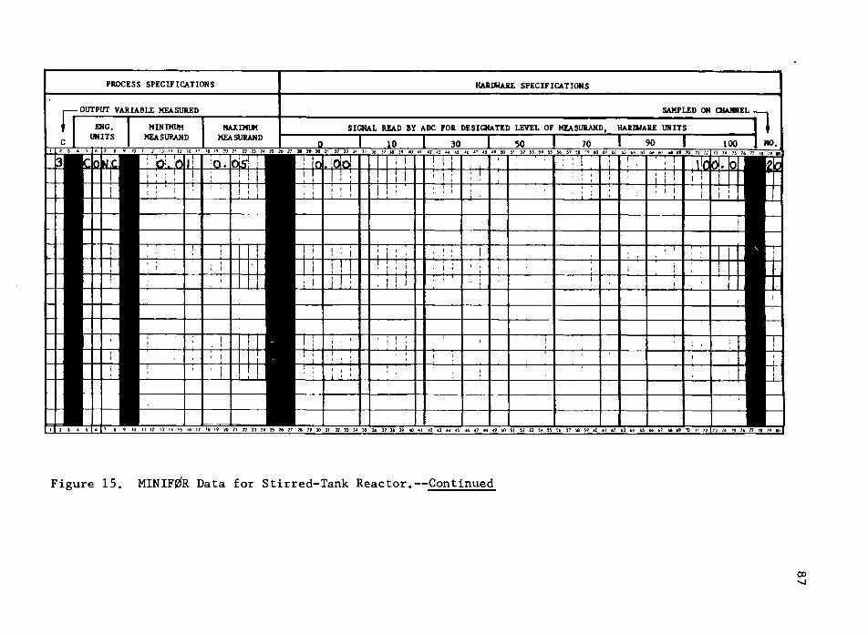
PROCESS SPECIFICATIONS HARDWARE SPECIFICATIONS
OUTPUT VARIABLE MEASURED SAMPLED ON CHANNELENG.UNITS
MINIMUMMEASURAND
MAXIMUMMEASURAND
SIGNAL READ BY ADC FOR DESIGNATED LEVEL OF MEASURAND, HARDWARE UNITS
F i g u r e 1 5 . M I N I F 0 R D a t a f o r S t i r r e d - T a n k R e a c t o r . — C o n t i n u e d
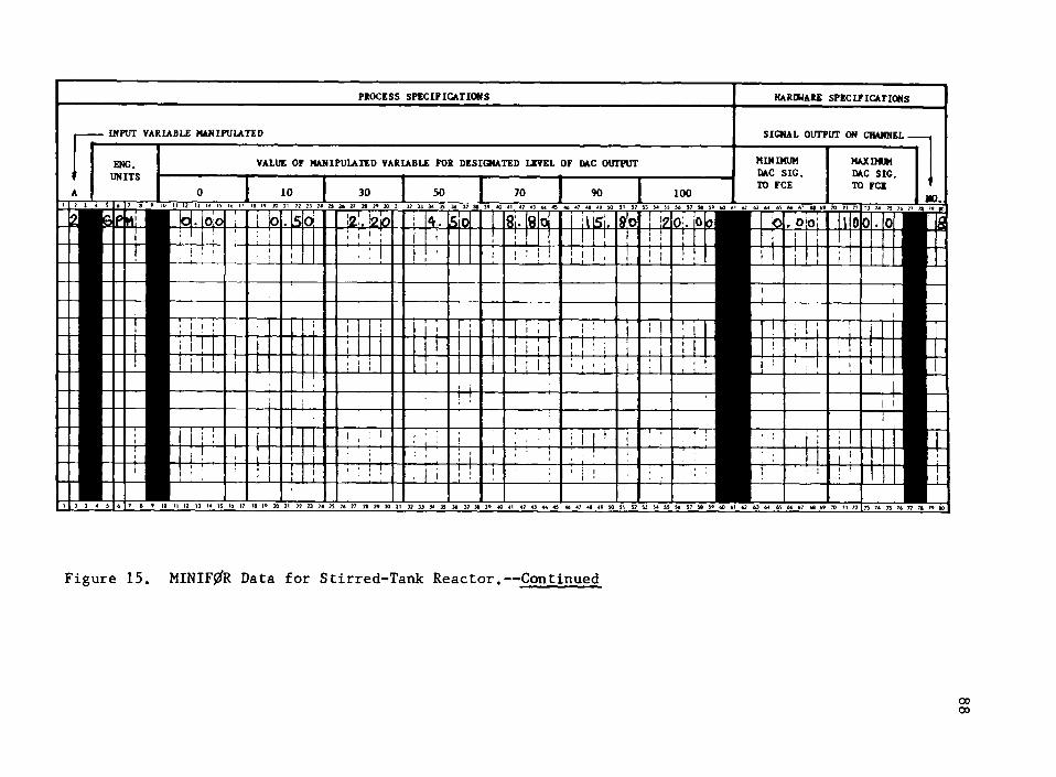
ENG. UNITS
PROCESS SPECIFICATIONS HARDWARE SPECIFICATIONS
SIGNAL OUTPUT ON CHANNEL
MINIMUM QAC SIC TO FCE
MAXIMUM DAC SIG. TO FCE
. 00
INPUT VARIABLE MANIPULATED
VALUE OF MANIPULATED VARIABLE FOR DESIGNATED LEVEL OF DAC OUTPUT
10 30 50 70 90 1006 7 a 9»0 H 12 >3 U !S 16 17 18 )9 20 21 72 73 ?4 25 a* 2? » 30 31 3? 33 34 35 36 37 38 40 41 4? 43 44 45 46 47 Ag A? 50 51 52 53 54 55 56 57 58 SO 60 67 63 6* 65
0.0
- 1 j
Sifi
! !J_ L
us.-I—LLLl •
- H -
On
6 7 8 9 10 II 12 13 1 4 15 16 17 18 1 9 20 21 ?2 23 74 2} 26 ?7 ?8 W 30 31 32 33 3< 35 36 37 38 39 40 41 4? *3 44 45 4* 47 46 4» 50 51 52 S3 54 55 56 57 56 5» 60 61 62 63 64 65 66 67 66 69 70 71 72
F i g u r e 1 5 . M I N I F 0 R D a t a f o r S t i r r e d - T a n k R e a c t o r . — C o n t i n u e d
oooo
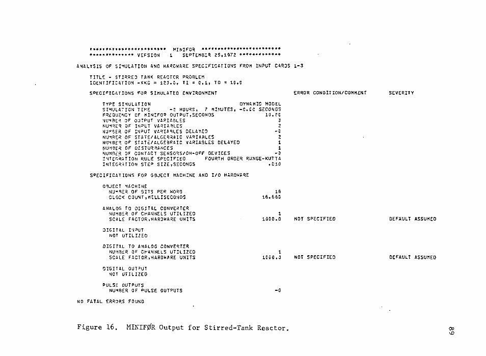
M I N I F C R * * * * * * * * * * * * * * * * * * * * * * * * *
V E F S I O N 1 S E P T E M B E R 2 5 , 1 9 7 2 * * * * * * * * * * * * *
A N A L Y S I S O F S I M U L A T I O N A N D H A R D W A R E S P E C I F I C A T I O N S F R O M I N P U T C A R O S 1 - 3T I T L E - S T I R R E D T A N K R E A C T O R P R O B L E M I D E N T I F I C A T I O N - X K C = 1 2 0 . C, T I = 0 . 1 , T D = 1 0 . 0S P E C I F I C A T I O N S F O R S I M U L A T E D E N V I R O N M E N T E R R O R C O N D I T I O N / C O M M E N T S E V E R I T Y
T Y P E S I M U L A T I O N D Y N A M I C M O D E LS I M U L A T I O N T I M E - 0 H O U R S , 7 M I N U T E S , - C . C C S E C O N D SF R E Q U E N C Y OF M I N I F O R O U T P U T , S E C O N D S 1 0 . CON U M B E R O F O U T P U T V A R I A B L E S 3N U M B E R O F I N P U T V A R I A B L E S 2N U M B E R O F I N P U T V A R I A B L E S D E L A Y E D -0N U M B E R O F S T A T E / A L G E B R A I C V A R I A B L E S 2N U M B E R OF S T A T E / A L G E B R A I C V A R I A B L E S D E L A Y E D 1N U M B E R O F D I S T U R B A N C E S 1N U M B E R O F C O N T A C T S E N S O R S / O N - O F F D E V I C E S -0I N T E G R A T I O N R U L E S P E C I F I E D F O U R T H O R D E R R U N G E - K U T T AI N T E G R A T I O N S T E p S I Z E , S E C O N D S . 0 1 0
S P E C I F I C A T I O N S F O P O B J E C T M A C H I N E A N D I / O H A R D W A R EO B J E C T M A C H I N E
N U M B E R O F B I T S P E R W O R D C L O C K C O U N T . M I L L I S E C O N D S
181 6 . 6 6 0
A N A L O G T O D I G I T A L C O N V E R T E R N U M B E R O F C H A N N E L S U T I L I Z E D S C A L E F A C T O R , H A R D W A R E U N I T S
11000.0 N O T S P E C I F I E D D E F A U L T
D I G I T A L I N P U T N O T U T I L I Z E D
D I G I T A L T O A N A L O G C O N V E R T E R N U M B E R O F C H A N N E L S U T I L I Z E D S C A L E F A C T O R , H A R D W A R E U N I T S
11000 .0 N O T S P E C I F I E D D E F A U L TD I G I T A L O U T P U T
N O T U T I L I Z E DP U L S E O U T P U T S
N U M B E R O F P U L S E O U T P U T S -0N O F A T A L E R R O R S F O U N D
A S S U M E D
A S S U M E D
F i g u r e 1 6 . M I N I F 0 R O u t p u t f o r S t i r r e d - T a n k R e a c t o r . 00
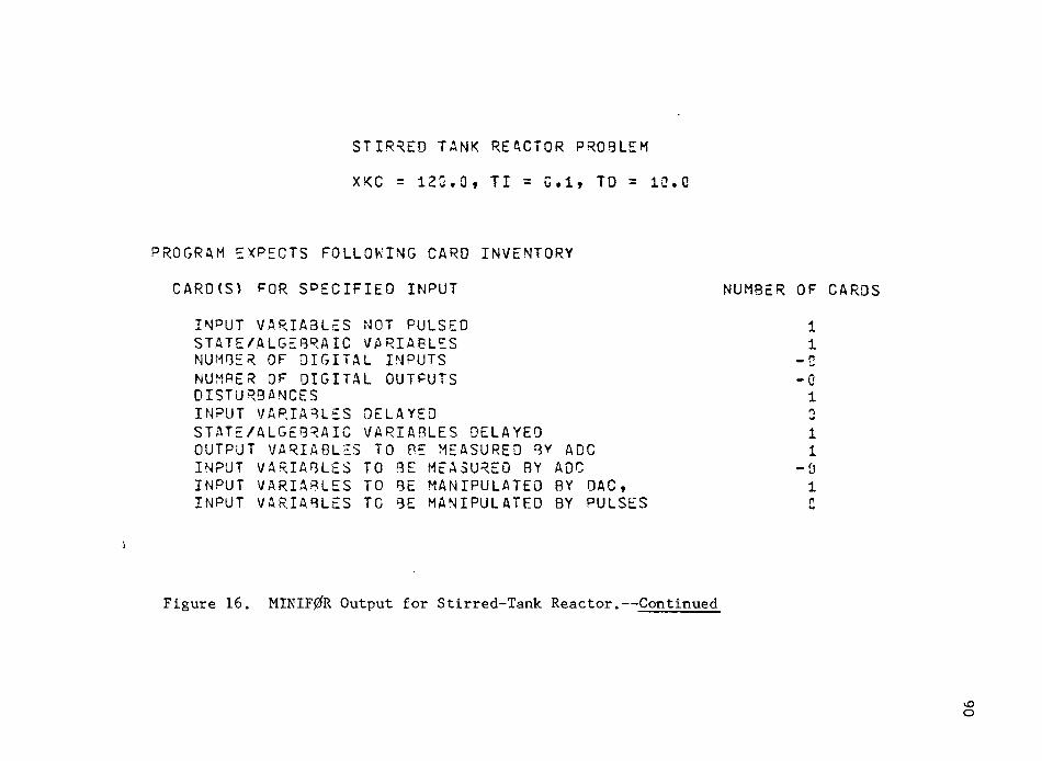
STIRRED TANK REACTOR PROBLEM
XKC = 120.0, II = G.l, TO = 10.0
P R O G R A M E X P E C T S F O L L O W I N G C A R O I N V E N T O R YC A R O ( S ) F O R S P E C I F I E D I N P U T N U M B E R O F C A R O S
I N P U T V A R I A B L E S N O T P U L S E D 1S T A T E / A L G E B R A I C V A R I A B L E S 1N U M B E R O F D I G I T A L I N P U T S - 0N U M B E R OF D I G I T A L O U T P U T S - 0D I S T U R B A N C E S 1I N P U T V A R I A B L E S D E L A Y E D 3S T A T E / A L G E B R A I C V A R I A B L E S D E L A Y E D 1O U T P U T V A R I A B L E S T O B E M E A S U R E D B Y A D C 1I N P U T V A R I A B L E S T O B E M E A S U R E D B Y A D C - 0I N P U T V A R I A B L E S T O B E M A N I P U L A T E D B Y O A C , 1I N P U T V A R I A B L E S T O B E M A N I P U L A T E D B Y P U L S E S C
\
F i g u r e 1 6 . M I N I F 0 R O u t p u t f o r S t i r r e d - T a n k R e a c t o r . — C o n t i n u e d
vOo
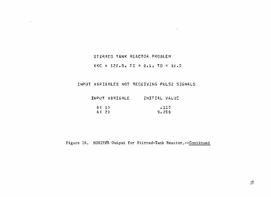
STIRRED TANK REACTOR PROBLEM
XKC = 120.0, TI = 0.1, TO = 10.0
I N P U T V A R I A B L E S N O T R E C E I V I N G P U L S E S I G N A L S
I N P U T V A R I A B L E I N I T I A L V A L U EA ( 1 ) . 1 0 0A ( 2 ) 9 . 3 5 0
Figure 16. MINIFgfR Output for Stirred-Tank Reactor.— Continued
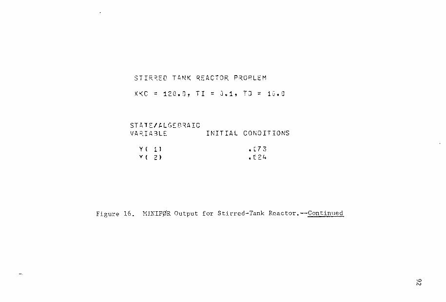
S T I R R E D T A N K R E A C T O R P R O B L E MX K C = 1 2 0 . 0 , T I = 3 . 1 , T O = 1 0 . 0
S T A T E / A L G E B R A I CV A R I A B L E I N I T I A L C O N D I T I O N SY ( 1 ) . C 7 3Y ( 2 ) . 1 2 4
Figure 16. MXNIF0R Output for Stirred-Tank Reactor.— Continued

STIRRED TANK REACTOR PROBLEM
XKC = 120.0, TI = 0.1, TO = 10.0
I N P U T V A R I A B L E D I S T U R B A N C E T I M E T O E N T E RD I S T U R B E D V A L U E S I M U L A T I O N , S E C .A ( 1 ) . 1 0 5 4 0 . 0 0
Figure 16. MINIF0R Output for Stirred-Tank Reactor.— Continued

STIRRED TANK REACTOR PROBLEM
XKC = 120.0, TI - 0.1, TO = 10.0
S T A T E / A L G E O R A I C D E A D T I M EV A R I A B L E S D E L A Y E D S E C O N D SY C 2 ) 3 0 . 0 0 0
Figure 16. MINIF0R Output for Stirred-Tank Reactor.— Continued

S T I R R E D T A N K R E A C T O R P R O B L E MXK C = 120.0, TI = 0.1, TO = 10. 0
S P E C I F I E D P R O C E S S / M O d E L " O U T P U T V A R I A B L E S T O BE M E A S U R E D BY A N A L O G T O D I G I T A L C O N V E R T E RP R O C E S S S P E C I F I C A T I O N S A N A L O G S I G N A L T O A Q C F O R D E S I G N A T E D L E V E L O F M E A S U R A N O , H O W E U N I T S
V A R I A B L E M I N I M U M M A X I M U M 0 10 30 50 7C 90 ICOM E A S U R E D U N I T S M E A S U F A N O M E A S U R A N O P E R C E N T . P E R C E N T P E R C E N T P E R C E N T P E R C E N T P E R C E N T P E R C E N TC < 3) C O N C . 0 1 . 0 5 0. 00 10 . 0 0 30 . 00 50 . 00 7 0 . CO 93. 00 1 0 0 . CO
S A M P L E D ON C H A N N E L23
Figure 16. MINIF0R Output for Stirred-Tank Reactor.— Continued

S T I R R E D T A N K R E A C T O R P R O B L E MXK C — 120*3? TI — G • 1 ? TO — 1C•0
S P E C I F I E D P R O C E S S / M O D E L I N P U T V A R I A B L E S T O B E M A N I P U L A T E D BY S I G N A L S F R O M D I G I T A L T O A N A L O G C O N V E R T E RP R O C E S S S P E C I F I C A T I O N S
I N P U TV A R I A B L EM A N I P U L A T E D U N I T S
V A L U E O F M A N I P U L A T E D V A R I A B L E F O R D E S I G N A T E D L E V E L O F O A C O U T P U T
AC 2) G P M
0P E R C E N T
O.CiO
1GP E R C E N T
.50
3CP E R C E N T
2.20
50P E R C E N T
4 . 5 U
70P E R C E N T
8 . 6 0P E R C E N T
1 5 . 8 0
ICCP E R C E N T
20.00
H A R D W A R E S P E C I F I C A T I O N SM I N I M U M M A X I M U M S I G N A LS I G N A L S I G N A L O U T P U T ON T O F C E TO F C E C H A N N E L
1.03 1 0 3 . 0 0 8
Figure 16. MINIF0R Output for Stirred-Tank Reactor.— Continued
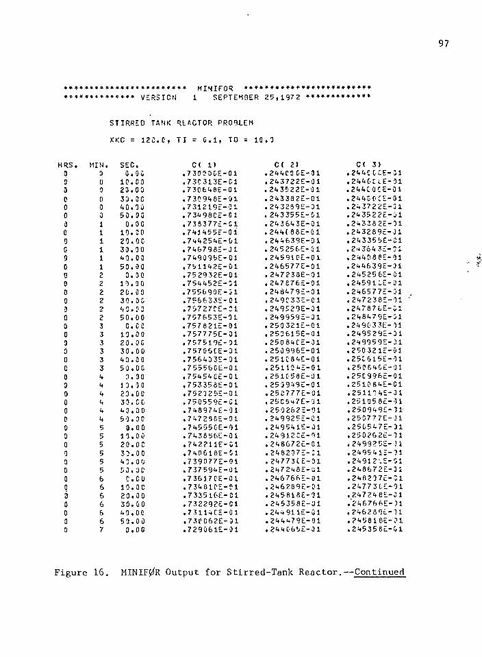
97
* * M I N I F O R ♦ * * ** * * * * * * * * * * * * * VE RSI ON 1 SEPTEMBER 2 5 , 1 9 7 2 + * + * * 4
S T I R R E D TANK REACTOR PROBLEM
XKC = 1 2 0 . 0 , T I = 0 . 1 , TO = 10 . 9
HRS . MI N . SEC. C( 1 ) C ( 2 ) C< 3 )0 3 0 . 0 C . 7 3 0 9 0 G E - 0 1 . 2 4 4 0 0 C E - 0 1 . 2 4 4 C C CE- 013 0 1 0 . 0 0 . 7 3 C 3 1 3 E - 0 1 . 2 4 3 7 2 2 5 - 0 1 . 2 4 4 CL v E - 9 10 0 2 3 . 0 3 . 7 3 0 - 6 4 BE- 0 1 . 2 4 3 5 2 2 E - 91 • 2 4 4 C 0 C E - C 10 0 3 3 . 0 0 . 7 3 C 9 4 6 E - 0 1 . 2 4 3 3 8 2 5 - 0 1 . 2 4 4 0 0 C E - 0 10 3 4 0 . 0 0 . 7 3 1 2 1 9 E - 01 . 2 4 3 2 8 9 5 - 0 1 . 2 4 3 7 2 2 E - 3 10 3 5 0 . 9 0 . 7 3 4 9 8 C E - C 1 . 2 4 3 3 5 5 E - 01 . 24 35 2 2 5 - 0 10 1 O.OC . 7 3 5 3 7 7 E - 0 1 . 2 4 3 6 4 3 5 - 0 1 . 2 4 3 3 8 2 5 - 9 10 1 1 0 . 0 0 . 7 4 1 4 5 5 2 - 0 1 . 2 4 4 ( 6 6 5 - 0 1 . 2 4 3 2 8 9 5 - 0 10 i 2 0 . 0 0 • 7 4 4 2 5 4 E - 0 1 . 2 4 4 6 3 9 E - 3 1 . 2 4 3 3 5 5 5 - 0 10 i 3 0 . 0 0 . 7 4 6 7 9 B E - 31 . 2 4 5 2 5 6 E - G 1 . 2 4 3 6 4 3 5 - 3 10 i 4 3 . 00 • 7 4 9 0 9 5 E - 01 . 2 4 5 9 1 0 5 - 0 1 . 2 4 4 0 8 8 5 - 9 10 1 5 0 . 0 0 . 7 5 1 1 4 2 E - 0 1 . 2 4 6 5 7 7 5 - 0 1 . 2 4 4 6 3 9 5 - 0 10 2 3 . 0 0 . 7 5 2 9 3 2 E - 0 1 . 2 4 7 2 3 8 5 - 0 1 . 2 4 5 2 5 6 5 - 0 10 2 1 0 . 0 0 . 7 5 4 4 5 2 5 - 3 1 . 2 4 7 8 7 6 5 - 9 1 • 2 4 5 9 1 C E - 0 10 2 2 0 . 0 0 . 7 5 5 6 9 0 E - 0 1 . 2 4 8 4 7 9 5 - 0 1 . 2 4 6 5 7 7 5 - 3 10 2 3 0 . 0 0 . 7 5 6 6 3 3 5 - 0 1 . 2 4 9 0 3 3 5 - 0 1 . 2 4 7 2 3 8 5 - 9 13 2 4 3 . 0 2 * 7 5 7 2 7 C E - C 1 . 2 4 9 5 2 9 E - 0 1 . 2 4 7 8 7 6 5 - 0 10 2 5 0 . 0 0 . 7 5 7 6 5 3 5 - 3 1 . 2 4 9 9 5 9 5 - 0 1 • 2 4 8 4 7 9 E - 310 3 O.CO . 7 5 7 8 2 1 5 - 0 1 . 2 5 0 3 2 1 5 - 0 1 . 2 4 9 0 3 3 5 - 9 10 3 1 0 . 0 0 . 7 5 7 7 7 5 E - 0 1 . 2 5 3 6 1 5 E - 0 1 . 2 4 9 5 2 9 5 - 3 10 3 2 0 . 0 0 . 7 5 7 5 1 9 5 - 9 1 . 2 5 0 8 4 C E - 0 1 . 2 4 9 9 5 9 5 - 3 10 3 3 0 . 0 0 . 7 5 7 0 6 C E - 3 1 . 2 5 0 9 9 6 5 - 0 1 . 2 5 0 3 2 1 5 - 0 10 3 4 0 . 0 0 . 7 5 6 4 3 3 5 - 0 1 . 2 5 1 C 8 4 E - 0 1 . 2 5 0 6 1 5 5 - 3 10 3 5 0 . 0 0 . 7 5 5 5 6 0 5 - 0 1 . 2 5 1 1 0 4 5 - 0 1 . 2 5 0 6 4 0 5 - 0 10 4 3 . 0 0 . 7 5 4 5 4 0 5 - 0 1 . 2 5 1 C 5 8 E - 9 1 . 2 5 C 9 9 6 E - 0 13 4 1 3 . 3 0 . 7 5 3 3 5 8 5 - 0 1 . 2 5 0 9 4 9 5 - 0 1 . 2 5 1 0 6 4 5 - 0 10 4 2 0 . 0 0 . 7 5 2 3 2 5 5 - 0 1 . 2 5 0 7 7 7 5 - 0 1 . 2 5 1 1 3 4 5 - 3 10 4 3 3 . CO . 7 5 0 5 5 9 5 - 0 1 . 2 5 C 5 4 7 E - 9 1 . 2 5 1 9 5 8 5 - 0 10 4 4 0 . 0 0 . 7 4 8 9 7 4 5 - 9 1 . 2 5 9 2 6 2 5 - 9 1 . 2 5 0 9 4 9 5 - 3 10 4 5 3 . 3 0 . 7 4 7 2 3 8 5 - 3 1 . 2 4 9 9 2 5 5 - 0 1 . 2 5 0 7 7 7 5 - 3 10 5 0 . 0 0 . 7 4 5 5 5 C E - 0 1 . 2 4 9 5 4 1 5 - 0 1 . 2 5 0 5 4 7 5 - 3 10 5 1 0 . 0 0 . 7 4 3 6 5 6 5 - 0 1 . 2 4 9 1 2 C 5 - 9 1 . 2 5 0 2 6 2 5 - 3 10 5 2 0 . 0 0 • 7 4 2 2 1 I E - 01 . 2 4 6 6 7 2 5 - 0 1 . 2 4 9 9 2 5 5 - 0 10 5 3 3 . 0 0 . 7 4 0 6 1 6 5 - 0 1 . 2 4 8 2 0 7 5 - 0 1 . 2 4 9 5 4 1 5 - 9 10 5 4 3 . 0 0 . 7 3 9 0 7 7 5 - 0 1 . 2 4 7 7 3 C E - D 1 • 2 4 9 1 2 ' . 5 - 0 1Q 5 5 0 . 3 0 . 7 3 7 5 9 4 5 - 0 1 . 2 4 7 2 4 8 5 - 0 1 . 2 4 8 6 7 2 5 - 3 10 6 O.CO • 7 3 6 1 7 C E - 0 1 . 2 4 6 7 6 6 5 - 0 1 . 2 4 8 2 3 7 5 - 3 10 6 1 0 . OC . 7 3 4 8 1 0 5 - 0 1 . 2 4 6 2 8 9 5 - 0 1 . 2 4 7 7 3 0 5 - 9 16 6 2 3 . 0 0 • 7 3 3 5 1 6 E - 0 1 . 2 4 5 6 1 8 5 - 3 1 . 2 4 7 2 4 8 5 - 3 10 6 3 0 . 0 0 . 7 3 2 2 9 2 E - 0 1 . 2 4 5 3 5 8 5 - 0 1 . 2 4 6 7 6 6 5 - 0 10 6 4 3 . 0 0 • 7 3 1 1 4 C E - 0 1 . 2 4 4 9 1 1 5 - 0 1 . 2 4 6 2 6 9 5 - 9 10 6 5 0 . 0 0 . 7 3 0 0 6 2 5 - 0 1 . 2 4 4 4 7 9 5 - 9 1 . 2 4 5 8 1 8 5 - 3 10 7 O.CO . 7 2 9 0 6 1 5 - 0 1 . 2 4 4 0 6 5 5 - 0 1 . 2 4 5 3 5 8 5 - 0 1
Figure 16. MXNIF0R Output for Stirred-Tank Reactor.— Continued
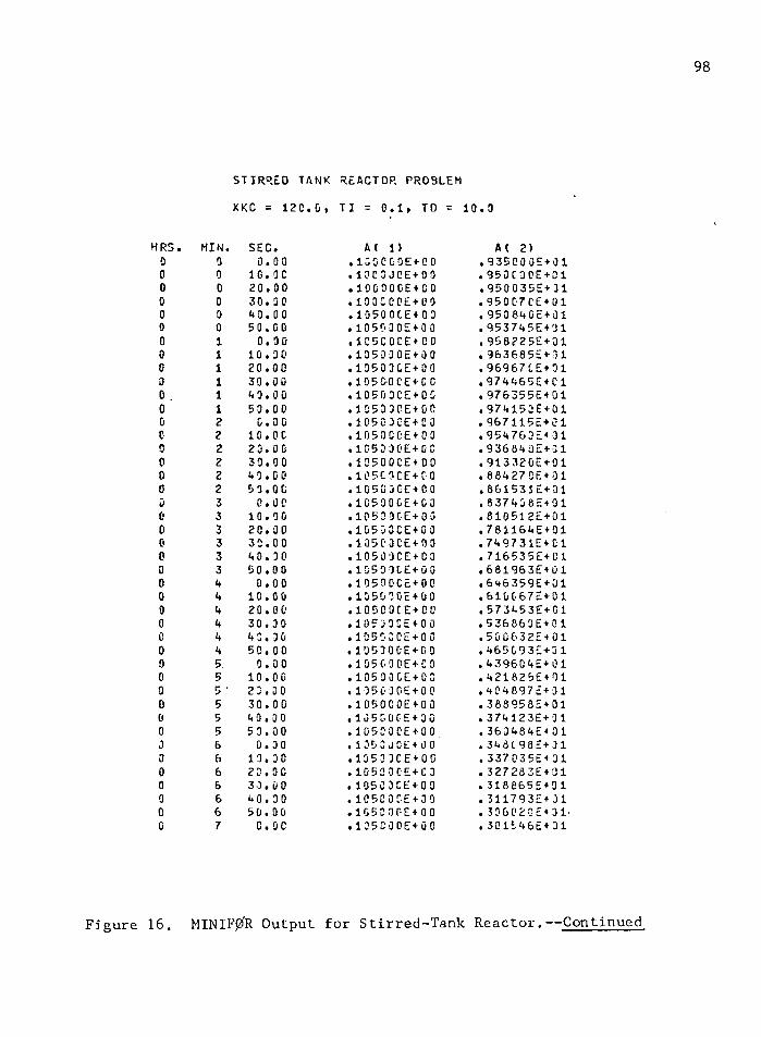
000000000Gc00000e0000000000000000J0000cG
98
STIRRED TANK REACTOR PROBLEM
XKC = 120.0, TI = 0.1, TD = 10.0
MIN. SEC. AC 1) AC 2)0 0.00 .1C00G0E+00 . 93500 0E + 010 10. oc .100 3JCE+0 0 .950C30E+010 20.00 .lOGOOOE+OO . 950 0 35E+ 310 30. 30 .100C 00E + O0 •950 07CE+010 40.00 .10500CE+00 .953840E+010 50.00 .1050 3 0E+00 .953745E+011 0.00 . 1C5C0GE + CD .956225E+011 10.00 .105000E+00 .963685E+011 20.00 . 10503CE + 00 . 96967 CE+011 30.00 • 1G5G-0CE + 00 .97 4465E+ C11 40.00 .1Q503CE+0G .976355E+011 50.00 .1050 30E+00 .974153E+012 0. 00 .10500CE+00 .967115E+012 10. OC .1050CCE+00 .954763E+312 20.00 .10530OE+OC .936640E+312 30.00 . 105000E + 00 .91332CE+012 40.00 •105C3CE+GC . 88427 CE+012 50.00 . 1050 0CE4 00 .861531E+013 0.00 •1C590GE+03 .8374362+013 10.00 .10500CE+00 .810512E+013 20.00 .1G503CE+03 .781164E+013 30.00 .105 0 OCE + OO .749731E+C13 40.00 .10509CE+03 .716535E+G13 50.00 .1050 0CE+00 .681963E+014 0.00 . 10530CE+00 •646359E+014 10.00 . 135070E4-00 .610067E+014 20.0 0 .105C0CE+CD .573453E+014 30.00 .10533CE+00 .536860E+014 4C.00 . 10503CE + 00 .500632E+014 50.00 .105300E+00 .465G93E+315 0.00 .105GODE+0 0 .439604E+015 10.00 .10500GE+03 .421825E+015 ' 2 3.00 . 1050 J0E + 0 0 .4046972+315 30.00 .105000E+00 .388958E+015 40.00 .1053005+30 .374123E+315 53.00 .105000E+00 . 363484E + 016 0.00 .1353J0E+00 . 348C 982+016 13.30 . 1350 3CE + 00 .337035E+316 23.00 .10530CE+C3 .327283E+016 33.0 0 .105 03CE+00 .318665E+016 40.00 .105000E+30 .311793E+J16 50.00 • 1G50 0PE+ 0 0 .3060202+317 c. 00 •135C0 0E+00 .301546E+31
MINIF0R Output for Stirred-Tank Reactor.— Continued
CHAPTER 4
SUMMARY AND SUGGESTED FUTURE DEVELOPMENT
MINIF0R is designed to facilitate minicomputer real-time
FORTRAN IV program development, debugging, and updating on a large
general purpose computere The system should aid program development
for minimum configuration dedicated minicomputer data acquisition and
process control applicationsc System real-time structure is built
around standard executive and process input/output interfaces estab
lished by the Fifth Workshop on Standardization of Industrial Computer
Languages* Paper tape FORTRAN IV source programs for processing on
the actual minicomputer application are produced by a card-to-tape
conversion program*
It is the authorr s opinion that MINIFgfR can be a productive
tool for debugging, developing, and updating real-time FORTRAN programs
used in industrial applications* Further, the system has potential for
wide usage in an academic environment for unit operation exercises and
studies in process control theory* Industrial acceptance of such
methodology depends upon vendor implementation of the standard inter
face calls soon to be published as ISA standards. It is this writerr s
opinion that users will recognize the advantages of standardized proc
ess calls and demand such vendor implementation.
If wide industrial usage is achieved, then the utility of the
system should be increased through further development. The following
99
100
discussion suggests areas where the program can be improved to increase
user utility. <
Simulation of several levels of process interrupts should be
explored* This will necessitate addressing the problem of reentrant
programming* Reentrancy is currently implemented on minicomputer sys
tems by duplicate common subroutines for each interrupt service routine
and by storing intermediate results using stack points.
Additional standard executive interfaces, START and TRNON, must
be incorporated in the system. These interfaces allow a designated
program to be executed after a specified time delay or at a specified
time of day. The designated program can be called from the program
clock, SUBROUTINE CLOCK, with minor modification.
MINIF0R can be made available to smaller systems through over
lays. Minor modifications could be made as follows: The MINIF0R
executive and common block would be core resident at all times. Since
subroutines INITAL and INCK are executed only at the beginning of a
simulation run, these subroutines can be overlayed by the remaining
system components.
Position and velocity control algorithms for conventional three
mode controllers using single set point, cascade, or ratio control
schemes could easily be included. These algorithms would be available
to the user for implementing DDC and SSP loops.
Variable step size integration routines, such as the Runge-
Kutta-Merson method as implemented by Wait (17), should be incorporated
into the system. This will require only minor modification of the

101
calling sequence in SUBROUTINE UPDATE. The system is presently struc
tured to implement dead time simulation using a variable step size in
tegration rule without modification of system routines for storing and
recalling values of delayed variables.
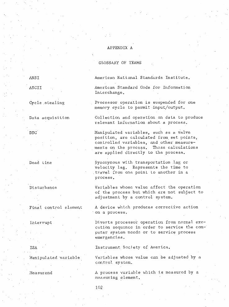
APPENDIX A
ANSI
ASCII
Cycle stealing
Data acquisition
DDC
Dead time
Disturbance
Final control element
Interrupt
ISA
Manipulated variable
Measurand
GLOSSARY OF TERMS
American National Standards Institute.
American Standard Code for Information Interchange.
Processor operation is suspended for one memory cycle to permit input/output.
Collection and operation on data to produce relevant information about a process.
Manipulated variables, such as a valve position, are calculated from set points, controlled variables, and other measurements on the process. These calculations are applied directly to the process.
Synonymous with transportation lag or velocity lag. Represents the time to travel from one point to another in a process.
Variables whose value affect the operation of the process but which are not subject to adjustment by a control system.
A device which produces corrective action on a process.
Diverts processor operation from normal execution sequence in order to service the computer system needs or to service process emergencies.
Instrument Society of America.
Variables whose value can be adjusted by a control system.
A process variable which is measured by a measuring element.
102
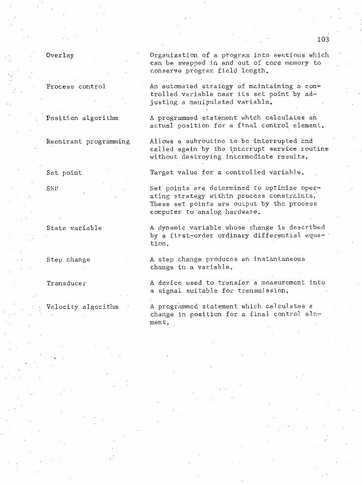
103
Overlay
Process control
Position algorithm
Reentrant programming
Set point
SSP
State variable;
Step change
Transducer
Velocity algorithm
Organization of a program into sections which can be swapped in and out of core memory to conserve program field length.
An automated strategy of maintaining a controlled variable near its set point by adjusting a manipulated variable.
A programmed statement which calculates an actual position for a final control element.
Allows a subroutine to be interrupted and called again by the interrupt service routine without destroying intermediate results.
Target value for a controlled variable.
Set points are determined to optimize operating strategy within process constraints. These set points are output by the process computer to analog hardware.
A dynamic variable whose change is described by a first-order ordinary differential equation.
A step change produces an instantaneous change in a variable.
A device used to transfer a measurement into a signal suitable for transmission.
A programmed statement which calculates a change in position for a final control element.

APPENDIX B
MINIF0R CODING FORMS
104
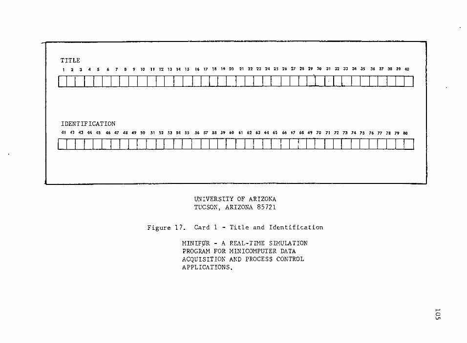
TITLE1 2 3 4 5 8 9 10 11 12 13 14 15 16 17 18 19 20 21 22 23 24 25 26 27 28 29 30 31 32 33 34 35 36 37 38 39 40
-V
IDENTIFICATION41 42 43 44 45 46 47 48 49 50 51 52 53 54 55 56 57 58 59 60 61 62 63 64 65 66 67 68 69 70 71 72 73 74 75 76 77 78 79 80
UNIVERSITY OF ARIZONA TUCSON, ARIZONA 85721
Figure 17. Card 1 - Title and Identification
MINIF0R - A REAL-TIME SIMULATION PROGRAM FOR MINICOMPUTER DATA ACQUISITION AND PROCESS CONTROL APPLICATIONS.
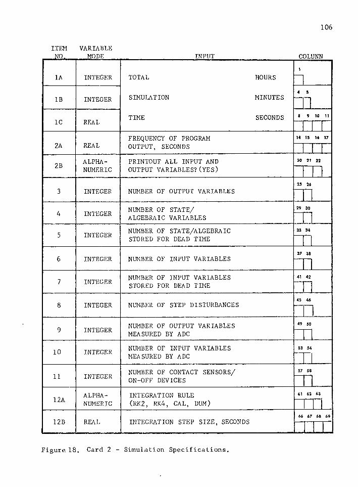
106
ITEM VARIABLENO. MODE_____________________ INPUT________________ COLUNN
1A INTEGER TOTAL HOURSi
IB INTEGER SIMULATION MINUTES 4 5
1C REAL TIME SECONDS S 9 10 11
2A REALFREQUENCY OF PROGRAM 14 15 16 17
OUTPUT, SECONDS
2B ALPHA PRINTOUT ALL INPUT AND 20 21 22
NUMERIC OUTPUT VARIABLES?(YES)
INTEGER NUMBER OF OUTPUT VARIABLES25 26
3
INTEGER NUMBER OF STATE/ 29 304 ALGEBRAIC VARIABLES
5 INTEGER NUMBER OF STATE/ALGEBRAIC 33 34
STORED FOR DEAD TIME
6 INTEGER NUMBER OF INPUT VARIABLES37 38
7 INTEGER NUMBER OF INPUT VARIABLES 41 42
STORED FOR DEAD TIME
8 INTEGER NUMBER OF STEP DISTURBANCES 45 46
9 INTEGER NUMBER OF OUTPUT VARIABLES 49 50
MEASURED BY ADC
10 INTEGER NUMBER OF INPUT VARIABLES MEASURED BY ADC
53 54
Tl11 INTEGER NUMBER OF CONTACT SENSORS/ 57 58
ON-OFF DEVICES
12A ALPHA INTEGRATION RULE 61 62 63
NUMERIC (RK2, RK4, CAL, DUM)
12B REAL INTEGRATION STEP SIZE, SECONDS66 67 68 69
Figure 18. Card 2 - Simulation Specifications.
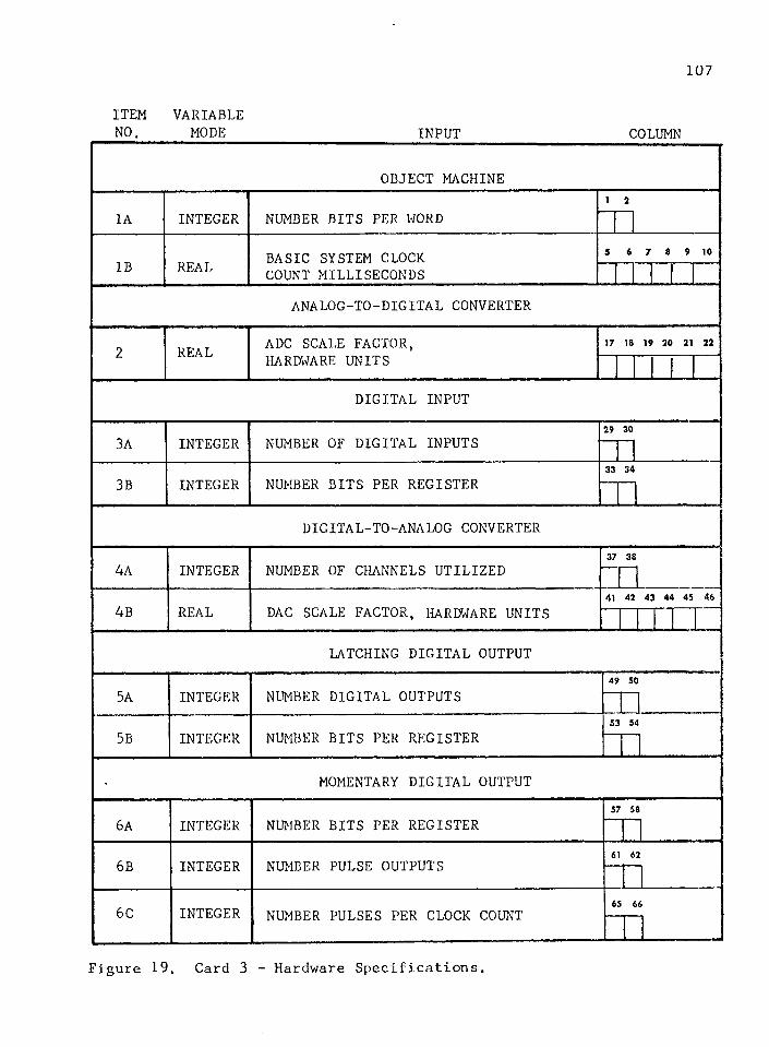
107
ITEM VARIABLENO. MODE INPUT COLUMN
OBJECT MACHINE
1A INTEGER NUMBER BITS PER WORDi 2
IB REAL BASIC SYSTEM CLOCK 3 6 7 8 9 10
COUNT MILLISECONDSANALOG-TO-DIGITAL CONVERTER
2 REAL ADC SCALE FACTOR, 17 18 19 20 21 22
HARDWARE UNITS
DIGITAL INPUT
3A INTEGER NUMBER OF DIGITAL INPUTS29 30
3B INTEGER NUMBER BITS PER REGISTER33 34
DIGITAL-TO-ANALOG CONVERTER
4A INTEGER NUMBER OF CHANNELS UTILIZED37 38
4B REAL DAC SCALE FACTOR, HARDWARE UNITS41 42 43 44 45 46
LATCHING DIGITAL OUTPUT
5A INTEGER NUMBER DIGITAL OUTPUTS49 50
5B INTEGER NUMBER BITS PER REGISTER53 54
MOMENTARY DIGITAL OUTPUT
6A INTEGER NUMBER BITS PER REGISTER57 58
6B INTEGER NUMBER PULSE OUTPUTS 61 62
6C INTEGER NUMBER PULSES PER CLOCK COUNT6! 66
Figure 19. Card 3 - Hardware Specifications.
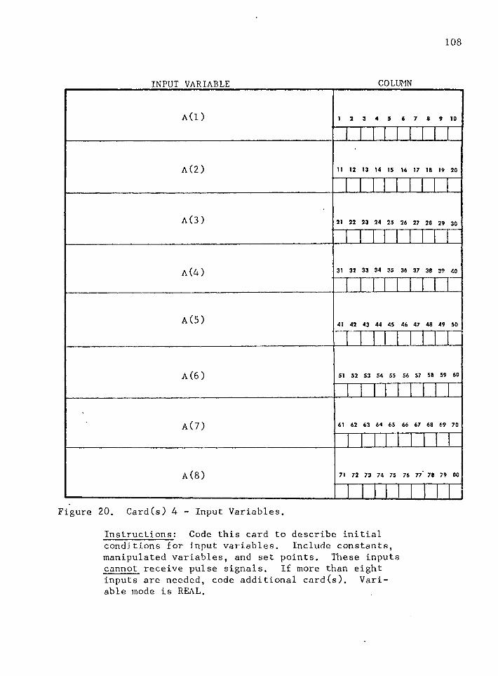
108
INPUT VARIABLE COLUMN
A (I ) 1 2 3 4 5 6 7 8 9 10
A(2) 11 12 13 14 15 16 17 18 19 20
A(3) 21 22 23 24 25 26 27 28 29 30
A(4) 31 32 33 34 35 36 37 38 39 40
A(5) 41 42 43 44 45 46 47 48 49 50
A(6) 51 52 53 54 55 56 57 58 59 60
A(7)
A(8)
61 62 63 64 65 66 67 68 69 70
71 72 73 74 75 76 77 78 79 CO
Figure 20. Card(s) 4 - Input Variables.
Instructions: Code this card to describe initialconditions for input variables. Include constants, manipulated variables, and set points. These inputs cannot receive pulse signals. If more than eight inputs are needed, code additional card(s). Variable mode is REAL.

109
STATE/ALGEBRAIC VARIABLE COLUMN
Y (l) i 2 3 4 5 6 7 8 9 10
Y(2) n 12 13 14 15 16 17 18 19 20
Y (3 ) 21 22 23 24 25 26 27 28 29 30
Y(4) 31 32 33 34 35 36 37 38 39 40
Y(5) 41 42 43 44 45 46 47 48 49 50
Y(6) 51 52 53 54 55 56 57 58 59 60
Y( 7 ) 61 62 63 64 65 66 67 68 69 70
Y(8) 71 72 73 74 75 76 77 78 79 80
Figure 21. Card(s) 5 - State/Algebraic Variables.
Instructions: Code this card to describe initial conditionsfor state/algebraic variables. If more than eight variables are needed, code additional card(s). Variable mode is REAL.
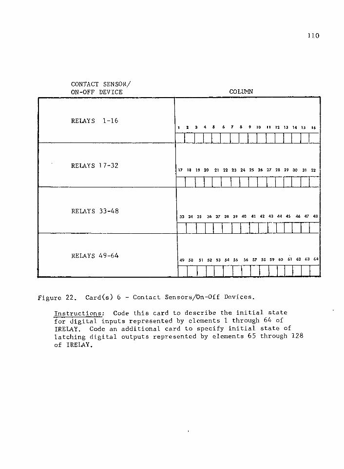
110
CONTACT SENSOR/ON-OFF DEVICE COLUMN
RELAYS 1-161 2 3 4 5 6 7 8 9 10 11 12 13 14 15 16
RELAYS 17-3217 18 19 20 21 22 23 24 25 26 27 28 29 30 31 32
RELAYS 33-4833 34 35 36 37 38 39 40 41 42 43 44 45 46 47 48
RELAYS 49-6449 50 51 52 53 54 55 56 57 58 59 60 61 62 63 64
Figure 22. Card(s) 6 - Contact Sensors/On-Off Devices.
Instructions: Code this card to describe the initial statefor digital inputs represented by elements 1 through 64 of IRELAY. Code an additional card to specify initial state of latching digital outputs represented by elements 65 through 128 of IRELAY.

Ill
VARIABLEMODE INPUT COLUMN
INTEGER INPUT VARIABLE DISTURBEDi 2
REAL TIME TO ENTER, SECONDS4 5 6 7 6 9 10
REAL DISTURBANCE VALUE11 12 13 14 15 16 17 18 19 20
INTEGER INPUT VARIABLE DISTURBED21 22
REAL TIME TO ENTER, SECONDS24 25 26 27 28 29 30
REAL DISTURBANCE VALUE31 32 33 34 35 36 37 38 39 40
INTEGER INPUT VARIABLE DISTURBED41 42
REAL TIME TO ENTER, SECONDS44 45 46 47 48 49 50
51 52 53 54 55 56 57 58 59 60
REAL DISTURBANCE VALUE
INTEGER INPUT VARIABLE DISTURBED61 62
REAL TIME TO ENTER, SECONDS64 65 66 67 68 69 70
REAL DISTURBANCE VALUE71 72 73 74 75 76 77 78 79 80
Figure 23. Card (s ) 7 - Disturbances.
Instructions: Code this card to program disturbances intothe simulation. Disturbances are in the form of step changes and are applicable to input variables only. If more than four disturbances are needed, code an additional card.
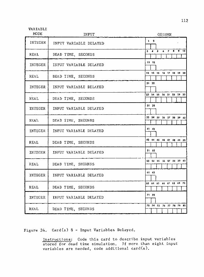
112
VARIABLEMODE INPUT COLUMN
INTEGER INPUT VARIABLE DELAYED i 2
REAL DEAD TIME, SECONDS3 4 5 6 7 8 9 10
INTEGER INPUT VARIABLE DELAYED 11 12
REAL DEAD TIME, SECONDS13 14 15 16 17 18 19 20
INTEGER INPUT VARIABLE DELAYED21 22
23 24 25 26 27 28 29 30
REAL DEAD TIME, SECONDS
INTEGER INPUT VARIABLE DELAYED31 32
REAL DEAD TIME, SECONDS33 34 35 36 37 38 39 40
INTEGER INPUT VARIABLE DELAYED 41 42
REAL DEAD TIME, SECONDS 43 44 45 46 47 48 49 50
INTEGER INPUT VARIABLE DELAYED 51 52
REAL DEAD TIME, SECONDS53 54 55 56 57 58 59 60
INTEGER INPUT VARIABLE DELAYED61 62
REAL DEAD TIME, SECONDS63 64 65 66 67 68 69 70
INTEGER INPUT VARIABLE DELAYED 71 72
REAL DEAD TIME, SECONDS73 74 75 76 77 78 79 80
Figure 24. Card(s) 8 - Input Variables Delayed.
Instructions: Code this card to describe input variablesstored for dead time simulation. If more than eight input variables are needed, code additional card(s).
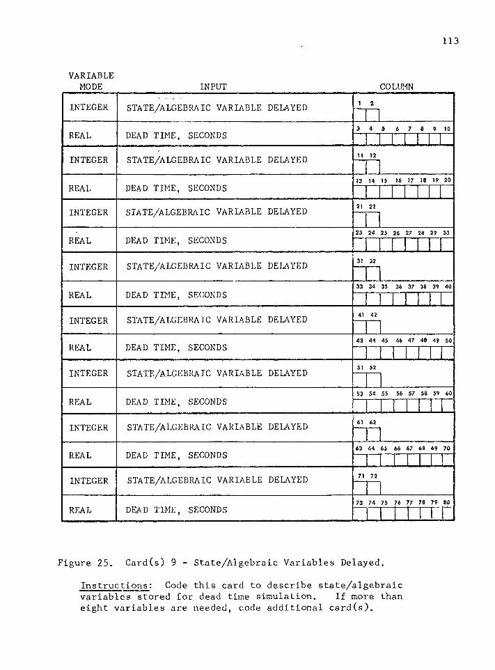
113
VARIABLEMODE INPUT COLUMN
INTEGER STATE/ALGEBRAIC VARIABLE DELAYED i 2
REAL DEAD TIME, SECONDS3 4 5 6 7 8 9 10
INTEGER STATE/ALGEBRAIC VARIABLE DELAYED 11 12
REAL DEAD TIME, SECONDS13 14 15 16 17 18 19 20
INTEGER STATE/ALGEBRAIC VARIABLE DELAYED 21 22
REAL DEAD TIME, SECONDS23 24 25 26 27 28 29 30
INTEGER STATE/ALGEBRAIC VARIABLE DELAYED 31 32
REAL DEAD TIME, SECONDS33 34 35 36 37 38 39 40
INTEGER STATE/ALGEBRAIC VARIABLE DELAYED 41 42
REAL DEAD TIME, SECONDS43 44 45 46 47 48 49 50
INTEGER STATE/ALGEBRAIC VARIABLE DELAYED 51 52
REAL DEAD TIME, SECONDS53 54 55 56 57 58 59 60
INTEGER STATE/ALGEBRAIC VARIABLE DELAYED 61 62
REAL DEAD TIME, SECONDS63 64 65 66 67 68 69 70
INTEGER STATE/ALGEBRAIC VARIABLE DELAYED 71 72
REAL DEAD TIME, SECONDS73 74 75 76 77 78 79 60
Figure 25. Card(s) 9 - State/Algebraic Variables Delayed.
Instructions: Code this card to describe state/algebraicvariables stored for dead time simulation. If more than eight variables are needed, code additional card(s).
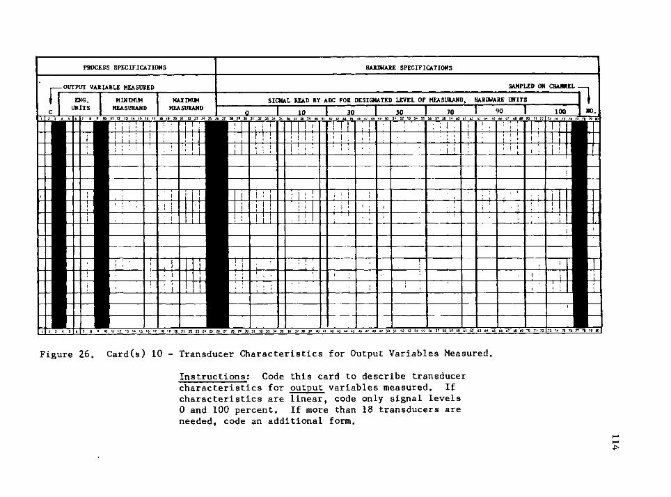
PROCESS SPECIFICATIONS HARDWARE SPECIFICATIONS
frOUTPUT VARIABLE MEASURED SAMPLED ON CHANNEL
1ENG.UNITS
MINIMUMMEASURAND
MAXIMUMMEASURAND
SIGNAL READ BY ADC FOR DESIGNATED LEVEL OF MEASURAND, HARDWARE UNITS10 1 30 1 50 1 70 1 90 100 NO.
7 8 * to II 17 13 H 11 16 17 IS l» 20 21 22 23 24 25 26 27 28 2? 30 31 32 33 34 35 36 37 38 39 40 41 47 43 44 45 46 47 48 49 SO 51 52 53 54 55 56 57 58 >9 60 61 6? 63 64 65 66 6? 68 » 70 71 77t— n
' M '
TT
i I
1—r-i—L
TTT' I
-r-M-
l I
I 2J 4 5 6 7 8 9 10 II 1? 13 14 15 16 17 18 19 20 21 72 23 24 25 26 27 28 79 30 31 32 33 34 35 36 37 38 39 40 41 42 43 44 45 46 47 48 49 50 51 52 53 54 55 56 5 7 58 59 60 61 6? 63 64 65 66 67 68 69 70 71 77 173 74 73 76 77 7| 79 80
73 74 75 76 77 78 79 80
F i g u r e 2 6 . C a r d ( s ) 1 0 - T r a n s d u c e r C h a r a c t e r i s t i c s f o r O u t p u t V a r i a b l e s M e a s u r e d ,I n s t r u c t i o n s : C o d e t h i s c a r d t o d e s c r i b e t r a n s d u c e rc h a r a c t e r i s t i c s f o r o u t p u t v a r i a b l e s m e a s u r e d . I f c h a r a c t e r i s t i c s a r e l i n e a r , c o d e o n l y s i g n a l l e v e l s 0 a n d 1 0 0 p e r c e n t . I f m o r e t h a n 1 8 t r a n s d u c e r s a r e n e e d e d , c o d e a n a d d i t i o n a l f o r m .
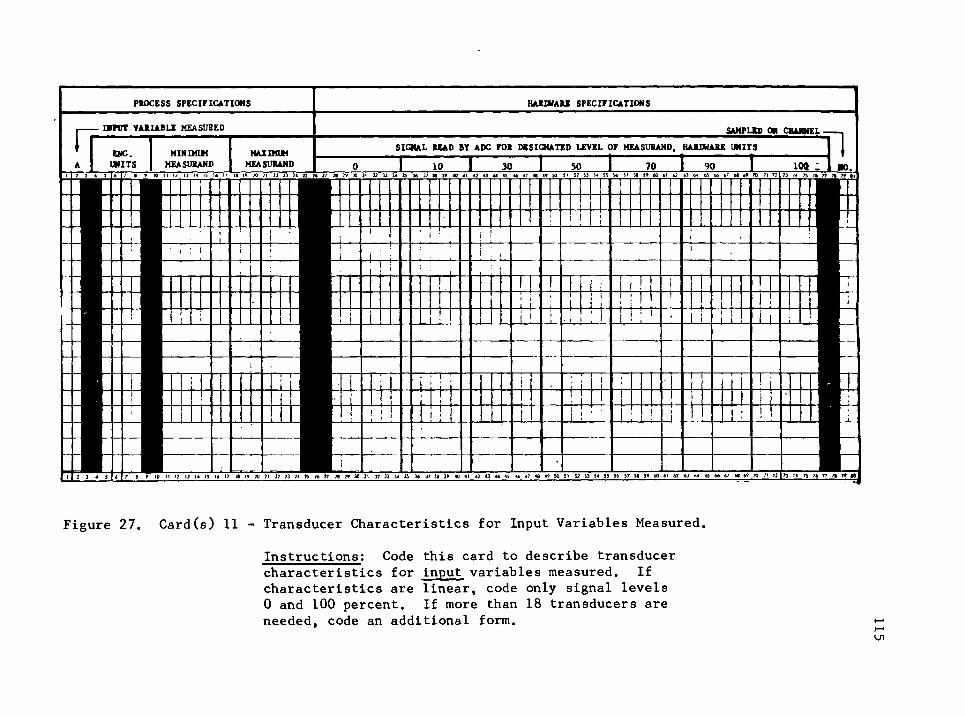
PKOCESS SPECIFICATIONS HAMVAEE SPECIFICATIONS
INPUT VARIABLE MEASURED SAMPLED ON CHANNEL
ENG. MINIMUM MAXIMUM SIGNAL BEAD BY ADC FOB DESIGNATED LEVEL OF MEASUBAND, HARDWARE UNITSUNITS MEASUBAND MEASUBAND 0 1 io 1 30 _ J . 50 _ _ 1 70 1 90 1 100 - NO.
1 } i i 6 > « f 10 111? 13 14 ts 14 17 H H 30 ?t » a M a I* « W 30 ]l I? 13 34 35 W 3» W 40 «l g 43 44 4t 47 « 49 SO SI 52 i3 54 S5 S6 >7 S« S» tO 61 6? tJ M tS 6t 67 70 71 72 73 74 7j 7« 77 7» lu
1 I
! i
1 : :i ' i 1
I !i i i i i
i i .
i 1 1 j i !
! i 1 1
:! i i j i
i 1 ! ; • 1 ! !! i • i ! i i ■ !
—
i i!
, ' i j
ii I 1 !
i 1 1 1 !
! 1 ! I I ii
| iI 7 3 4 3 4 7 6 9 >0 II 17 13 14 15 16 17 16 19 20 21 22 23 24 23 74 27 26 29 30 31 32 33 34 33 36 37 36 39 40 41 42 43 44 4} 46 47 46 49 30 51 52 S3 34 33 56 37 36 39 60 61 62 63 >4 65 66 67 66 69 70 71 72 1 73 74 73 76 77 71 79 W
F i g u r e 2 7 . C a r d ( s ) 1 1 - T r a n s d u c e r C h a r a c t e r i s t i c s f o r I n p u t V a r i a b l e s M e a s u r e d ,I n s t r u c t i o n s : C o d e t h i s c a r d t o d e s c r i b e t r a n s d u c e rc h a r a c t e r i s t i c s f o r i n p u t v a r i a b l e s m e a s u r e d . I f c h a r a c t e r i s t i c s a r e l i n e a r , c o d e o n l y s i g n a l l e v e l s 0 a n d 1 0 0 p e r c e n t . I f m o r e t h a n 1 8 t r a n s d u c e r s a r e n e e d e d , c o d e a n a d d i t i o n a l f o r m . 115
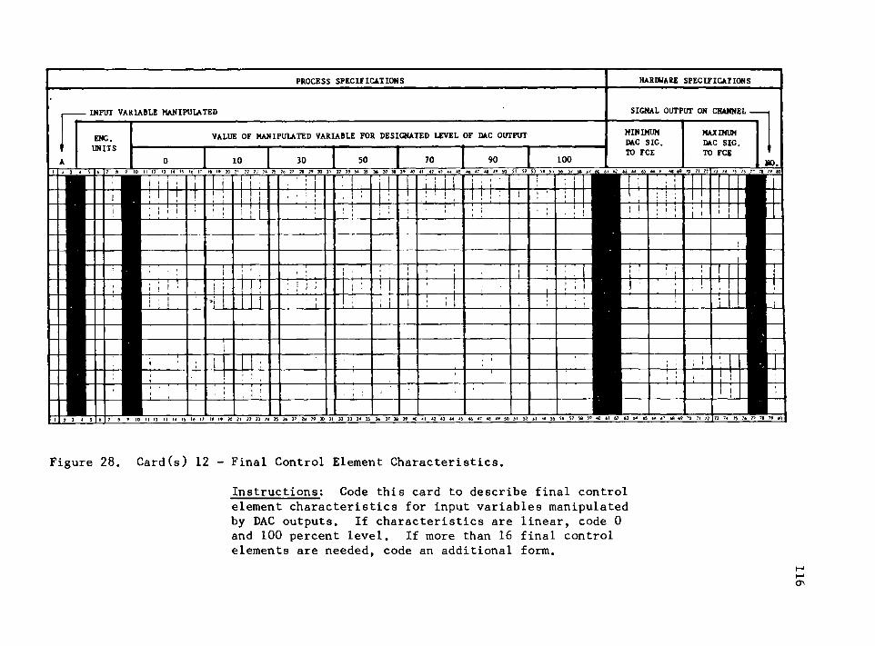
PROCESS SPECIFICATIONS HARDWARE SPECIFICATIONS
INPUT VARIABLE MANIPULATED SIGNAL OUTPUT ON CHANNEL
ENG.UNITS
VALUE OF MANIPULATED VARIABLE FOR DESIGNATED LEVEL OF DAC OUTPUT MINIMUM DAC SIC.
MAXIMUM DAC SIG.
0 10 30 50 70 90 100TO FCE TO FCE
N0.- 7 ; T ' T -
1 11 .
! ' 1 | ! 1 ■ i i i 1 i j -' | ;■ ;
; 1 1 ! ! I • ' ; ! ; : : ' 1 ! ! M 1I |
; ! I j j 1 : ! i 11 ' • ; I
; . • i ! r~ i : l} ’ [ "! . | 1
i l l ! I 1 : i i ; ! I : ! 1 I : 1 | ! ! !! : i i 1 ; i i i ! ! ! , ■ ;
i1 . ! ' i : : 11 ■ ; : , ' 1
i • ■ ' ; . , i ; : : . j ; ■ ' '
61 62 W M 66 f S8 70 71 7?
-l—l-
I 2 3 4 5 6 7 8 9 10 II 12 13 14 15 16 17 18 16 20 21 2 2 2 3 24 25 2 6 2 ? 28 29 30 31 33 33 34 35 36 3 7 38 3 9 40 41 42 43 44 45 46 47 48 46 50 51 5) 53 54 55 56 57 5* 5« 60 61 62 63 64 65 6 6 67 68 66 "O 71 72 1 73 74 75 76 77 7» 79 80
73 74 74 7 6 7 7 78 7 9 80
I I
F i g u r e 2 8 . C a r d ( s ) 1 2 - F i n a l C o n t r o l E l e m e n t C h a r a c t e r i s t i c s .I n s t r u c t i o n s : C o d e t h i s c a r d t o d e s c r i b e f i n a l c o n t r o le l e m e n t c h a r a c t e r i s t i c s f o r i n p u t v a r i a b l e s m a n i p u l a t e d b y D A C o u t p u t s . I f c h a r a c t e r i s t i c s a r e l i n e a r , c o d e 0 a n d 1 0 0 p e r c e n t l e v e l . I f m o r e t h a n 1 6 f i n a l c o n t r o l e l e m e n t s a r e n e e d e d , c o d e a n a d d i t i o n a l f o r m .
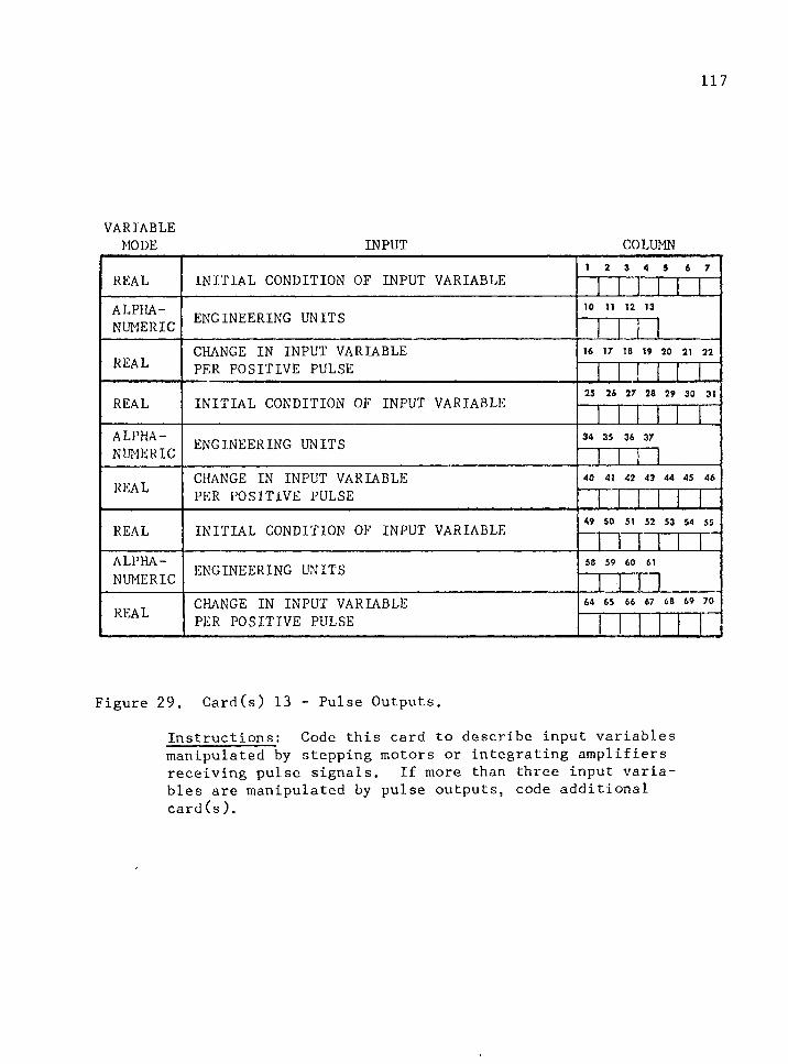
117
VARIABLEMODE INPUT COLUMN
REAL INITIAL CONDITION OF INPUT VARIABLEi 2 3 4 5 6 7
ALPHA ENGINEERING UNITS10 11 12 13
NUMERIC
REALCHANGE IN INPUT VARIABLE 16 17 18 19 20 21 22
PER POSITIVE PULSE
REAL INITIAL CONDITION OF INPUT VARIABLE 25 26 27 28 29 30 31
ALPHA ENGINEERING UNITS 34 35 36 37
NUMERIC
REAL CHANGE IN INPUT VARIABLE 40 41 42 43 44 45 46
PER POSITIVE PULSE
REAL INITIAL CONDITION OF INPUT VARIABLE 49 50 51 52 53 54 55
n t . JALPHA ENGINEERING UNITS 58 59 60 61
NUMERIC
REAL CHANGE IN INPUT VARIABLE 64 65 66 67 68 69 70
PER POSITIVE PULSE I
Figure 29. Card(s) 13 - Pulse Outputs.
Instructions: Code this card to describe input variablesmanipulated by stepping motors or integrating amplifiers receiving pulse signals. If more than three input variables are manipulated by pulse outputs, code additional card(s).
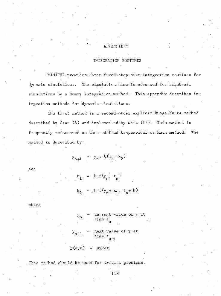
APPENDIX C
INTEGRATION ROUTINES
MINTFjZfR provides three £ixed~step size integration routines for
dynamic simulationse The simulation time is advanced for algebraic
simulations by a dummy integration method. This appendix describes in
tegration methods for dynamic simulations.
The first method is a second-order explicit Runge-Rutta method
described by Gear (6) and implemented by Wait (17). This method is
frequently referenced as the modified trapezoidal or Heun method. The
method is described by
w - v ^ Wand
h = h f(V tn)
kg = h f(yn+ t^+ h)
where
y = current value of y atn time t n
y - = next value of y atn+l time t ,n+l
' . f(y, t) = dy/dt
This method should be used for trivial problems.
118
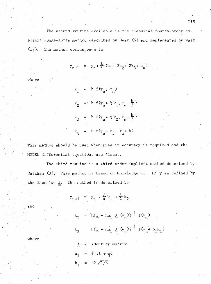
119
The second routine available is the classical fourth-order ex
plicit. Runge-Kutta method described by Gear (6) and implemented by Wait
(17), The method corresponds to
yn+l = V ? (kl+ 2k2+ 2k3+ k4) ■
where
kl = h f(yn’ tn )
k2 = h f(yn+ % k l» tn+ T )
k 3 = h f(yn + % k 2 , tn + |-) '
k, " h f (y + k0, t + h)4 n 3’ n
This method should be used when greater accuracy is required and the
MODEL differential equations are linear.
The third routine is. a third-order implicit method described by
Calahan (3). This method is based on knowledge of f/ y as defined by
the Jacobian J, The method is described by
and
where
'n+l = yn + 4 kl + 4 k2
kl = h[I - haL J (yn )]~1 f Cyn )
kg = h[I - ha1 J (yn)] 1 f (yn-f )
= identity matrix
■= h (1 + j)bj- = ~2 Vl/3

120
Galatian1s method is recommended by Gear (6) for solution of systems of
nonlinear stiff differential equations. Since it is an implicit method.,
a simultaneous system of equations is solved at each step. Moler's
(13) matrix triangularization by Gaussian elimination and linear equa
tion solver routines are utilized. The method fails if the coefficient
matrix formed by [I.-ha^ J_ (y )] is singular. MINIF0R prints a diagnos
tic when this occurs; the user should then select another integration
method.
When using Galatian's method in the time varying case, a change
of variable should, be used. For example, let
YD0T(1) = 1.0
which has the solution Y(l) = T. Then substitute Y(l) for T in other
state equations where T appears.
REFERENCES
1e Buckley, Page S. 1964. Techniques of Process Control, John Wiley and Sons, Inc., New York City, New York.
2. Butler, J. L. 1970. Comparative Criteria for Minicomputers,Instrum. Technol. 17:67-82.
3C Calahan, D. A. 1968. A Stable Accurate Method of Numerical Integration for Non-linear Systems, Proc. IEEE ‘56:744.
4. Coughanowr, D. R., and Koppel, L. B. 1965. Process Systems Analysis and Control, McGraw-Hill Co., New York City, New York.
5. Digital Equipment Corporation Advertisement.' 1972. Electron. 45:29.
6. Gear, C. W„ 1971. Numerical Initial Value Problems in Ordinary Differential Equations, Prentice-Hall, Inc., Englewood Cliffs,N. J.
7. Jarvis, P. H. 1968. Some Experiences with Process Control Languages, IEEE Trans, on Indust. Electron, and Control Instrum. 15: 54-56.
8. Kaenel, Reg. A. 1970. Minicomputers - A Profile of Tomorrow’s Component, IEEE Trans, Audio Electroacoust. 18:354-379.
9. Marks, C. H., and Skillern, J. A. 1964. Transmitters for Computer Information Systems, ISA J. 11:73-76.
10. Mensh, M. , and Diehl, W,. 1968. Extended FORTRAN for Process Control, IEEE Trans, on Indust. Electron, and Control Instrum. 15:75- 79.
11.» Minutes, Fifth Workshop on Standardization of Industrial Computer Languages. 1971. Purdue Laboratory for Applied Industrial Control , Purdue University, Lafayette, Indiana.
12o Minutes, Sixth Workshop on Standardization of Industrial ComputerLanguages. 1972. Purdue Laboratory for Applied Industrial Control, Purdue University, Lafayette, Indiana.
13. Moler, Cleve B. 1972. Algorithm 423, Linear Equation Solver (F4),Comm, of the ACM 15:274.
121
122
14, Murphy, John A, 1971, Minicomputers, Modern Data 5_: 58-72.
15, Roberts, Bert C. 1968. FORTRAN IV in a Process Control Environment, IEEE rans, on Indust. Electron, and Control Instrum. 15: 61-63.
16. Spencer, Henry W., Shepardson, Harlon P., and McGowan, Larry M. 1970. Small Computer Software, IEEE Comput. Group News 3j15^20.
17. Wait, John V. 1971. FORTRAN Subroutines for Continuous System Simulation, IfCSRL Memo 223, n Department of Electrical Engineering, University of Arizona, Tucson, Arizona.
.18. White, James Wm. Private communication, Department of Chemical Engineering, University of Arizona, Tucson, Arizona. 1972.
19. Williams, Theodore J. (ed.). 1970. Emulator, Simulator, andTranslator Programs for the Small Digital Computers Necessary for Medical Laboratory Automation, Purdue Laboratory for Applied Industrial Control, Purdue University, Lafayette, Indiana.

mmm m *