MINI VERTICAL MILLING/ DRILLING MACHINEmanuals.harborfreight.com/manuals/44000-44999/44991.pdf ·...
14
MINI VERTICAL MILLING/ DRILLING MACHINE ASSEMBLY AND OPERATING INSTRUCTIONS 3491 Mission Oaks Blvd., Camarillo, CA 93011 Visit our Web site at http://www.harborfreight.com Copyright © 2000 by Harbor Freight Tools ® . All rights reserved. No portion of this manual or any artwork contained herein may be reproduced in any shape or form without the express written consent of Harbor Freight Tools. For technical questions and replacement parts, please call 1-800-444-3353 44991
Transcript of MINI VERTICAL MILLING/ DRILLING MACHINEmanuals.harborfreight.com/manuals/44000-44999/44991.pdf ·...

MINI VERTICAL MILLING/DRILLING MACHINE
ASSEMBLY AND OPERATING INSTRUCTIONS
3491 Mission Oaks Blvd., Camarillo, CA 93011 Visit our Web site at http://www.harborfreight.com
Copyright © 2000 by Harbor Freight Tools®. All rights reserved. No portion of this manual or any artwork contained herein may be reproduced in any shape or form without the express written consent of Harbor Freight Tools.
For technical questions and replacement parts, please call 1-800-444-3353
44991

Page 2SKU 44991
SpecificationsITEM DESCRIPTION
Power Consumption 120 VAC, 60 Hz, single phaseMotor 4/5 HPSpeed Ranges 0 ~ 1100 low RPM and 0 ~ 2500 high RPMSpindle R-8 TaperChuck JT33 Taper; 7/64 to 1/2 inch capacityEnd Mill Capacity 1/2 inchFace Mill Capacity 1 inchDrill Capacity 1/2 inchMicro Feed Scale 0.002 inch per lineDepth Scale 0 to 12 inches in 1/16 inch incrementsTable Slot Width 1/2 inchTable Size 15-7/8 (L) x 3-11/16 (W) inchesUnit Height 33-11/16 inchesWeight 115 lbs.
Save This ManualYou will need the manual for the safety warnings and precautions, assembly instructions, operating and maintenance procedures, parts list and diagram. Keep your invoice with this manual. Write the invoice number on the inside of the front cover. Keep the manual and invoice in a safe and dry place for future reference.
Safety Warnings and PrecautionsWARNING: When using tool, basic safety precautions should always be followed to reduce the risk of personal injury and damage to equipment.
Read all instructions before using this tool!
1. Keep work area clean. Cluttered areas invite injuries.
2. Observe work area conditions. Do not use machines or power tools in damp or wet locations. Don’t expose to rain. Keep work area well lighted. Do not use electrically powered tools in the presence of flammable gases or liquids.
3. Keep children away. Children must never be allowed in the work area. Do not let them handle machines, tools, or extension cords.
4. Store idle equipment. When not in use, tools must be stored in a dry location to inhibit rust. Always lock up tools and keep out of reach of children.
5. Do not force tool. It will do the job better and more safely at the rate for which it was intended. Do not use inappropriate attachments in an attempt to exceed the tool capacity.
6. Use the right tool for the job. Do not attempt to force a small tool or attachment to
0.0019
1/2 inch15-1/3 inch x 3-2/3 inch28-1/3 inch
Page 3SKU 44991
do the work of a larger industrial tool. There are certain applications for which this tool was designed. Do not modify this tool and do not use this tool for a purpose for which it was not intended.
7. Dress properly. Do not wear loose clothing or jewelry as they can be caught in moving parts. Protective, electrically non-conductive clothes and non-skid footwear are recommended when working. Wear restrictive hair covering to contain long hair.
8. Use eye and ear protection. Always wear ANSI approved impact safety goggles. Wear a full face shield if you are producing metal filings. Wear an ANSI approved dust mask or respirator when working around metal and chemical dusts and mists.
9. Do not overreach. Keep proper footing and balance at all times. Do not reach over or across running machines.
10. Maintain tools with care. Keep tools sharp and clean for better and safer performance. Follow instructions for lubricating and changing accessories. Inspect tool cords periodically and, if damaged, have them repaired by an authorized technician. The handles must be kept clean, dry, and free from oil and grease at all times.
11. Disconnect power. Unplug tool when not in use.
12. Remove adjusting keys and wrenches. Check that keys and adjusting wrenches are removed from the tool or machine work surface before plugging it in.
13. Avoid unintentional starting. Be sure the switch is in the Off position when not in use and before plugging in.
14. Stay alert. Watch what you are doing, use common sense. Do not operate any tool when you are tired.
15. Check for damaged parts. Before using any tool, any part that appears damaged should be carefully checked to determine that it will operate properly and perform its intended function. Check for alignment and binding of moving parts; any broken parts or mounting fixtures; and any other condition that may affect proper operation. Any part that is damaged should be properly repaired or replaced by a qualified technician. Do not use the tool if any switch does not turn On and Off properly.
16. Guard against electric shock. Prevent body contact with grounded surfaces such as pipes, radiators, ranges, and refrigerator enclosures.
17. Replacement parts and accessories. When servicing, use only identical replacement parts. Use of any other parts will void the warranty. Only use accessories intended for use with this tool. Approved accessories are available from Harbor Freight Tools.
18. Do not operate tool if under the influence of alcohol or drugs. Read warning labels on prescriptions to determine if your judgment or reflexes are impaired while taking drugs. If there is any doubt, do not operate the tool.
19. Use proper size and type extension cord. If an extension cord is required, it must be of the proper size and type to supply the correct current to the tool without heating
Page 4SKU 44991
up. Otherwise, the extension cord could melt and catch fire, or cause electrical damage to the tool. This tool requires use of an extension cord of 0 to 10 amps capability (up to 50 feet), with wire size rated at 18 AWG. Longer extension cords require larger size wire. If you are using the tool outdoors, use an extension cord rated for outdoor use. (signified by “WA” on the jacket).
21. Maintenance. For your safety, service and maintenance should be performed regularly by a qualified technician.
Note: Performance of this tool (if powered by line voltage) may vary depending on variations in local line voltage. Extension cord usage may also affect tool performance.
Warning: The warnings, cautions, and instructions discussed in this instruction manual cannot cover all possible conditions and situations that may occur. It must be under-stood by the operator that common sense and caution are factors which cannot be built into this product, but must be supplied by the operator.
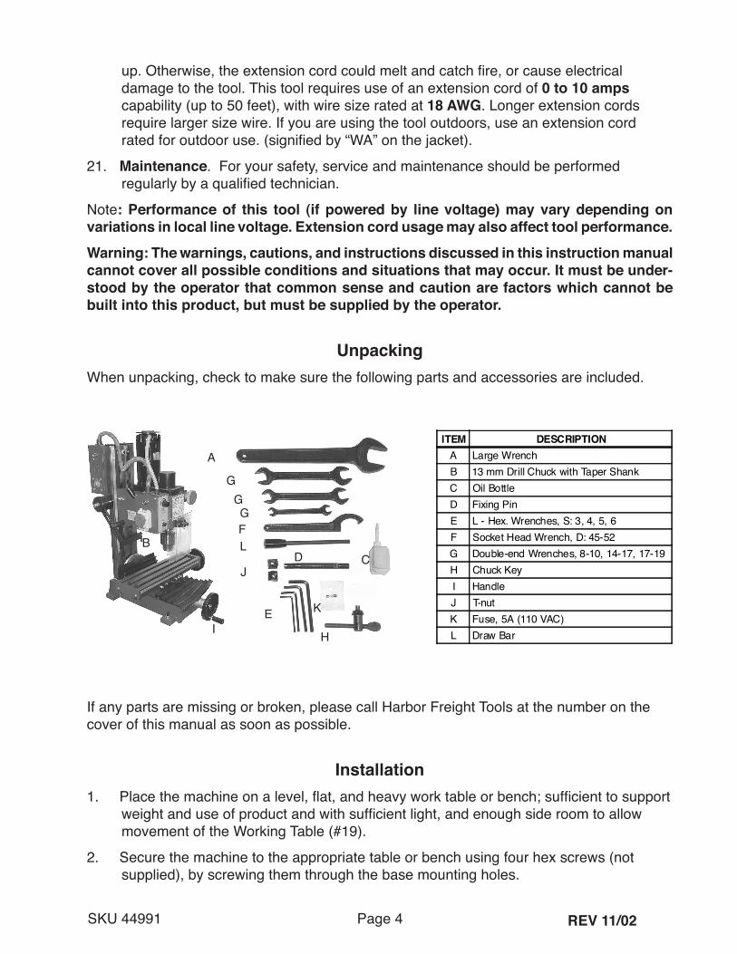
UnpackingWhen unpacking, check to make sure the following parts and accessories are included.
If any parts are missing or broken, please call Harbor Freight Tools at the number on the cover of this manual as soon as possible.
Installation1. Place the machine on a level, flat, and heavy work table or bench; sufficient to support
weight and use of product and with sufficient light, and enough side room to allow movement of the Working Table (#19).
2. Secure the machine to the appropriate table or bench using four hex screws (not supplied), by screwing them through the base mounting holes.
REV 11/02
ITEM DESCRIPTIONA Large WrenchB 13 mm Drill Chuck with Taper ShankC Oil BottleD Fixing PinE L - Hex. Wrenches, S: 3, 4, 5, 6F Socket Head Wrench, D: 45-52G Double-end Wrenches, 8-10, 14-17, 17-19H Chuck KeyI HandleJ T-nutK Fuse, 5A (110 VAC)L Draw Bar
A
BCD
E
F
GGG
H
L
J
KI
Page 5SKU 44991
3. An optional oil pan can be placed under the machine before it is mounted to the table.
4. Before operation, loosen the slide, worktable, and drill-mill spindle. They were locked for shipping.
5. Remove all packing material and clean machine with nonflammable solvent. Oil the machine according to the lubrication requirements before running the machine.
Assembly1. Install the Chuck.
- Thoroughly clean the tapered hole in the Chuck (164) and the Spindle (79) shaft of all dirt, grease, oil, and protective coatings (paint thinner may be necessary). - Slide the Chuck onto the Spindle shaft. - Turn the Chuck sleeve clockwise and open the jaws completely. - Tap the nose of the Chuck lightly with a piece of wood to securely set the Chuck.
2. If necessary, screw the Handles into the Small Hand Wheels.
3. Check the angle of the Vertical Support (68) for true vertical. Check all bolts for tightness.
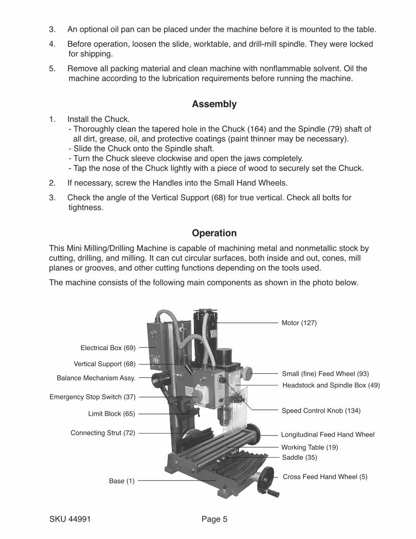
OperationThis Mini Milling/Drilling Machine is capable of machining metal and nonmetallic stock by cutting, drilling, and milling. It can cut circular surfaces, both inside and out, cones, mill planes or grooves, and other cutting functions depending on the tools used.
The machine consists of the following main components as shown in the photo below.
Motor (127)
Small (fine) Feed Wheel (93)Headstock and Spindle Box (49)
Cross Feed Hand Wheel (5)
Working Table (19)Saddle (35)
Longitudinal Feed Hand Wheel
Base (1)
Connecting Strut (72)
Limit Block (65)
Emergency Stop Switch (37)
Balance Mechanism Assy.
Vertical Support (68)
Electrical Box (69)
Speed Control Knob (134)
Page 6SKU 44991
Checks before Operation1. Turn on the machine by lifting the cover and pulling out the Emergency Stop Switch
(137).
2. Turn the Speed Control Knob (134) and verify spindle speed changes.
3. Verify that the spindle is rotating clockwise.
4. Operate the Longitudinal Axis (Working Table), Cross Axis (Saddle Seat), and Vertical Axis (Vertical Support), and verify their proper operation and movement.
Caution: Avoid injury to you or damage to machine. Unplug the power cord from the electrical outlet before performing any adjustments, tool replacement, or maintenance.
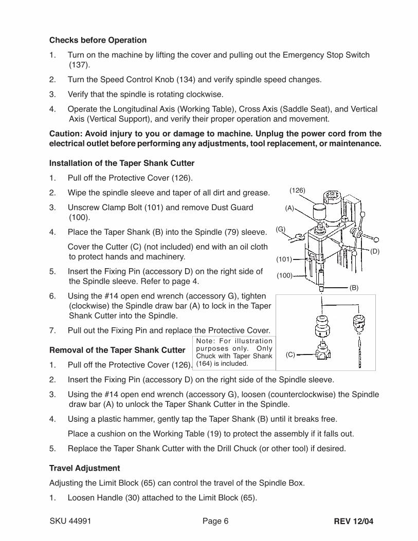
Installation of the Taper Shank Cutter1. Pull off the Protective Cover (126).
2. Wipe the spindle sleeve and taper of all dirt and grease.
3. Unscrew Clamp Bolt (101) and remove Dust Guard (100).
4. Place the Taper Shank (B) into the Spindle (79) sleeve.
Cover the Cutter (C) (not included) end with an oil cloth to protect hands and machinery.
5. Insert the Fixing Pin (accessory D) on the right side of the Spindle sleeve. Refer to page 4.
6. Using the #14 open end wrench (accessory G), tighten (clockwise) the Spindle draw bar (A) to lock in the Taper Shank Cutter into the Spindle.
7. Pull out the Fixing Pin and replace the Protective Cover.
Removal of the Taper Shank Cutter
1. Pull off the Protective Cover (126).
2. Insert the Fixing Pin (accessory D) on the right side of the Spindle sleeve.
3. Using the #14 open end wrench (accessory G), loosen (counterclockwise) the Spindle draw bar (A) to unlock the Taper Shank Cutter in the Spindle.
4. Using a plastic hammer, gently tap the Taper Shank (B) until it breaks free.
Place a cushion on the Working Table (19) to protect the assembly if it falls out.
5. Replace the Taper Shank Cutter with the Drill Chuck (or other tool) if desired.
Travel AdjustmentAdjusting the Limit Block (65) can control the travel of the Spindle Box.
1. Loosen Handle (30) attached to the Limit Block (65).
REV 12/04
(126)
(A)
(101)
(100)
(B)
(C)
(D)
(G)
Note: For i l lustration purposes only. Only Chuck with Taper Shank (164) is included.
Page 7SKU 44991
2. Adjust the position of the Limit Block (65) up or down. Refer to the Ruler (67) on the side of the Vertical Support (68).
3. Tighten the Handle.
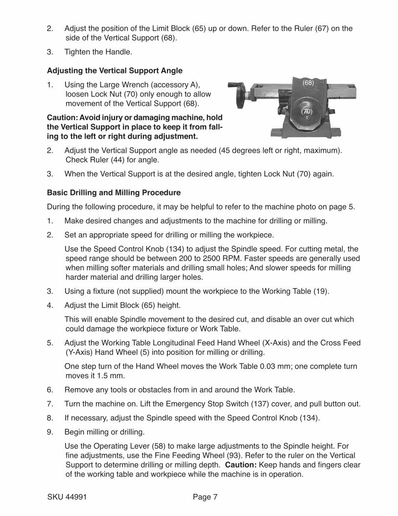
Adjusting the Vertical Support Angle
1. Using the Large Wrench (accessory A), loosen Lock Nut (70) only enough to allow movement of the Vertical Support (68).
Caution: Avoid injury or damaging machine, hold the Vertical Support in place to keep it from fall-ing to the left or right during adjustment.
2. Adjust the Vertical Support angle as needed (45 degrees left or right, maximum). Check Ruler (44) for angle.
3. When the Vertical Support is at the desired angle, tighten Lock Nut (70) again.
Basic Drilling and Milling Procedure
During the following procedure, it may be helpful to refer to the machine photo on page 5.
1. Make desired changes and adjustments to the machine for drilling or milling.
2. Set an appropriate speed for drilling or milling the workpiece.
Use the Speed Control Knob (134) to adjust the Spindle speed. For cutting metal, the speed range should be between 200 to 2500 RPM. Faster speeds are generally used when milling softer materials and drilling small holes; And slower speeds for milling harder material and drilling larger holes.
3. Using a fixture (not supplied) mount the workpiece to the Working Table (19).
4. Adjust the Limit Block (65) height.
This will enable Spindle movement to the desired cut, and disable an over cut which could damage the workpiece fixture or Work Table.
5. Adjust the Working Table Longitudinal Feed Hand Wheel (X-Axis) and the Cross Feed (Y-Axis) Hand Wheel (5) into position for milling or drilling.
One step turn of the Hand Wheel moves the Work Table 0.03 mm; one complete turn moves it 1.5 mm.
6. Remove any tools or obstacles from in and around the Work Table.
7. Turn the machine on. Lift the Emergency Stop Switch (137) cover, and pull button out.
8. If necessary, adjust the Spindle speed with the Speed Control Knob (134).
9. Begin milling or drilling.
Use the Operating Lever (58) to make large adjustments to the Spindle height. For fine adjustments, use the Fine Feeding Wheel (93). Refer to the ruler on the Vertical Support to determine drilling or milling depth. Caution: Keep hands and fingers clear of the working table and workpiece while the machine is in operation.
(68)
(70)
Page 8SKU 44991
10. When the drilling or milling is completed, press in on the Emergency Stop Switch and close its cover.
11. Unplug the line cord from the electrical outlet and clean the machine of all debris.
MaintenanceCaution: Avoid injuries or damage to equipment. Before performing any maintenance on this machine, unplug the power cord from the electrical outlet.
Lubrication Requirements1. Using a light oil and clean cloth, after each use, wipe down all metal parts of the
machine to prevent rusting.
2. Using machine lubrication grease, periodically apply to the X-axis feed screw (saddle seat), Y-axis feed screw (working table), and Z-axis feed gear rack (vertical support).
Periodic General Maintenance
1. Inspect all moving parts for lack of lubrication. If necessary, lubricate as described above.
2. Using compressed air, blow the machine clean of all foreign material. Wear eye protection during this operation.
3. Check all adjustment screws, bolts, and handles for tightness.
4. Store cutting tools in a wooden box or other moisture proof package.
5. Cover the machine when not in use.
6. Sharpen cutting tools as soon as they become dull.
7. Always keep the taper shank clean.
8. Store all tools and accessories in a clean and dry location, near the machine.
9. Always use the supplied tools and wrenches to make repairs and adjustments.
PLEASE READ THE FOLLOWING CAREFULLY
THE MANUFACTURER AND/OR DISTRIBUTOR HAS PROVIDED THE PARTS DIAGRAM IN THIS MANUAL AS A REFERENCE TOOL ONLY. NEITHER THE MANUFACTURER NOR DISTRIBUTOR MAKES ANY REPRESENTATION OR WARRANTY OF ANY KIND TO THE BUYER THAT HE OR SHE IS QUALIFIED TO MAKE ANY REPAIRS TO THE PRODUCT OR THAT HE OR SHE IS QUALIFIED TO REPLACE ANY PARTS OF THE PRODUCT. IN FACT, THE MANUFACTURER AND/OR DISTRIBUTOR EXPRESSLY STATES THAT ALL REPAIRS AND PARTS REPLACEMENTS SHOULD BE UNDERTAKEN BY CERTIFIED AND LICENSED TECHNICIANS AND NOT BY THE BUYER. THE BUYER ASSUMES ALL RISK AND LIABILITY ARISING OUT OF HIS OR HER REPAIRS TO THE ORIGINAL PRODUCT OR REPLACEMENT PARTS THERETO, OR ARISING OUT OF HIS OR HER INSTALLATION OF REPLACEMENT PARTS THERETO.

Page 9SKU 44991
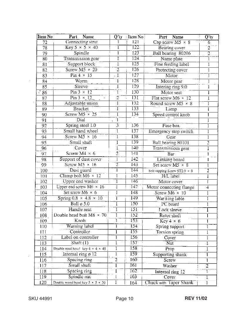
Parts List
NOTE: Some parts are listed and shown for illustration purposes only and are not available individually as replacement parts.
4
REV 03/05
Page 10SKU 44991
with
REV 11/02
Page 11SKU 44991
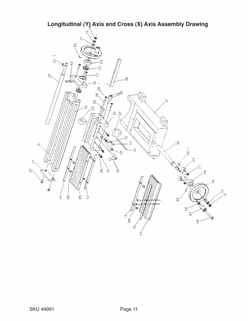
Longitudinal (Y) Axis and Cross (X) Axis Assembly Drawing
Page 12SKU 44991
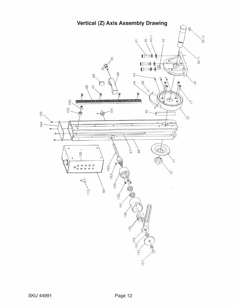
Vertical (Z) Axis Assembly Drawing
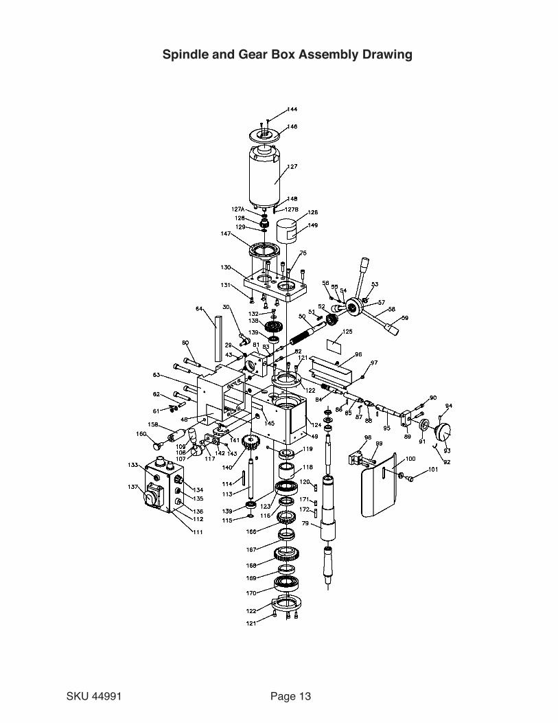
Page 13SKU 44991
Spindle and Gear Box Assembly Drawing

Limited 90 Day Warranty
Harbor Freight Tools Co. makes every effort to assure that its products meet high quality and durability standards, and warrants to the original purchaser that this product is free from defects in materials and workmanship for the period of 90 days from the date of purchase. This warranty does not apply to damage due directly or indirectly, to misuse, abuse, negligence or accidents, repairs or alterations outside our facilities, criminal activity, improper installation, normal wear and tear, or to lack of maintenance. We shall in no event be liable for death, injuries to persons or property, or for incidental, contingent, special or consequential damages arising from the use of our product. Some states do not allow the exclusion or limitation of incidental or consequential damages, so the above limitation of exclusion may not apply to you. THIS WARRANTY IS EXPRESSLY IN LIEU OF ALL OTHER WARRANTIES, EXPRESS OR IMPLIED, INCLUDING THE WARRANTIES OF MERCHANTABILITY AND FITNESS.To take advantage of this warranty, the product or part must be returned to us with transportation charges prepaid. Proof of purchase date and an explanation of the complaint must accompany the merchandise. If our inspection verifies the defect, we will either repair or replace the product at our election or we may elect to refund the purchase price if we cannot readily and quickly provide you with a replacement. We will return repaired products at our expense, but if we determine there is no defect, or that the defect resulted from causes not within the scope of our warranty, then you must bear the cost of returning the product.This warranty gives you specific legal rights and you may also have other rights which vary from state to state.
3491 Mission Oaks Blvd. • PO Box 6009 • Camarillo, CA 93011 • (800) 444-3353

![Metalworking] Milling Grinding Drilling](https://static.fdocuments.in/doc/165x107/577d36861a28ab3a6b93563a/metalworking-milling-grinding-drilling.jpg)