Mini-Hermet Pressure Switches - Electrical Solutions...
16
Mini-Hermet Pressure Switches Form 456 Registered Quality System to ISO 9001 are robust field-mounted instruments. The pressure sensing assembly is similar to a conventional SOR type. The main difference is that the switching element assembly is hermetically sealed in an explosion proof steel capsule. Switching elements are SPDT or DPDT. See Principle description on page 2. Application Information The pressure switches in this catalog are suitable for a variety of process applications in hazardous locations and hostile environments where stainless steel exterior parts are required and where space is limited. Basic models with standard wetted parts are normally suitable for air, oil, water and non-corrosive process fluids. See the Quick Selection Guide on page 4. Corrosive service and particular user requirements may require optional components. See How to Order on page 3. Adjustable ranges to accommodate lower Set Points, switching elements to handle heavier electrical loads and user preference may require Big Hermet models. High pressure fluid power (hydraulic) applications where high shock pressures and high cycle rates are expected normally require Pivot Seal type pressure switches. Mini-Hermet Pressure Switches
Transcript of Mini-Hermet Pressure Switches - Electrical Solutions...

1Registered Quality System to ISO 9001
Mini-HermetPressure Switches
Form 456
Registered Quality System to ISO 9001
are robust field-mountedinstruments. The pressure sensing assembly issimilar to a conventional SOR type. The maindifference is that the switching elementassembly is hermetically sealed in an explosionproof steel capsule. Switching elements areSPDT or DPDT. See Principle description onpage 2.
Application InformationThe pressure switches in this catalog aresuitable for a variety of process applications inhazardous locations and hostile environmentswhere stainless steel exterior parts are requiredand where space is limited. Basic models withstandard wetted parts are normally suitable forair, oil, water and non-corrosive process fluids.See the Quick Selection Guide on page 4.Corrosive service and particular userrequirements may require optional components.See How to Order on page 3. Adjustableranges to accommodate lower Set Points,switching elements to handle heavier electricalloads and user preference may require BigHermet models.
High pressure fluid power (hydraulic)applications where high shock pressures andhigh cycle rates are expected normally requirePivot Seal type pressure switches.
Mini-Hermet PressureSwitches

2 Registered Quality System to ISO 9001
Principle
Mini-HermetPressure Switches
Featu
res a
nd B
en
efits Built-In Quality
� Rigid quality standardsmaintained from raw material tofinished product.
Explosion Proof Hermetically SealedSwitching Capsule� Isolates switching elements from
corrosive, hostile and hazardousenvironments and virtually eliminatesproblems from corrosion.
UL Listed, CENELEC (BASEEFA), CSACertified, SAA and JIS/RIIS ApprovedModels� Meet most code and customer
requirements.
Field Adjustable Set Points� Full range adjustability without
disconnecting electrical power whilemaintaining explosion proof integrity,self-locking adjustment, no charge forfactory calibration.
Warranty���3 years from date of manufacture.
Instrument Quality� High resolution of Set Points, high
repeatability, narrow dead band, negligibletemperature effect, high overrange andproof pressures.
Robust Construction� High cycle rate tolerance, long life, not
critical to vibration, protected internalhermetically sealed switching elementcapsule.
Cost Effective� Simple, fast installation without special
tools, long service life. Periodic service orspare parts not required.
Delivery� Routine shipments 7 to 10 working days.
Emergency shipments via air within48 hours.
Service� Factory service engineers and area
factory representatives provide effectiveand prompt worldwide service.
The pressure sensing element of the SOR PressureSwitch is a force-balance, piston-actuatedassembly. The sensing element is sealed by aflexible diaphragm and a static o-ring. There areonly three wetted parts in this arrangement: apressure port, a diaphragm and an o-ring. A wideselection of wetted parts materials for mediacompatibility and containment are available. Ametal diaphragm may be welded to the pressureport for certain applications, thereby eliminating theo-ring (Designators U8 and U9).
Media pressure on the piston counteracts the forceof the range spring (adjustable by the adjustingscrew) which moves the piston shaft only a fewthousandths of an inch to directly actuate theelectrical snap-action switching element that isenclosed in the hermetically sealed steel capsule.This design results in low friction and virtually nowear. The electrical switching element is isolatedfrom corrosive atmospheres.
1/2” NPT(M)Electrical
Connection
Buna-N O-Ring
Electrical Switching Elements
Explosion Proof Hermetically Sealed SwitchingElement CapsuleActuator Lever
AssemblyAgency Approvals
& Ratings Tagfor Switching
Element Capsule
Piston ShaftNameplate:
Data Bearing and Agency Approvals/
Ratings
U8 Fire-Safe Welded
Diaphragm System
Pressure Port
FactorySealedElectrical Leads
Glass-to-MetalSeal
WeathertightCap
WeathertightGasket andCap Retainer
Set PointAdjusting Screw
External GroundLug BG,BH, & JHHousing Only
Range Spring
Piston Assembly
O-Ring(Not Installedon WeldedDiaphragm Systems)
Vinton O-RingWeathertight Seal

3Registered Quality System to ISO 9001
Quick Selection GuideBasic Mini-Hermet pressure switches in AG or AH housings with standard wetted parts are normally suitablefor air, oil, water and non-corrosive process applications in hazardous locations and hostile environmentswhere space is limited. Refer to the Quick Selection Guide section on page 4 for a basic model number.Corrosive service and particular customer requirements may require optional components. Refer to How toOrder section below to build a customized model number or the dedicated page to locate optionalcomponents, such as: switching elements, diaphragm systems, pressure ports and accessories. Eachposition in the model number, except Accessories, must have a designator.
6AG-EF3-M4-C2A-YYModel Number System
Piston Housing Diaphragm& O-Ring
SwitchingElement
RangeSpring
Pressure Port Accessories
ApplicationsMini-Hermet pressure switches in the AG and AH housings are normally suitable for a variety of processapplications in hazardous locations and hostile environments because the electrical switching elements arehermetically sealed in a stainless steel capsule that is UL Listed, CSA Certified and SAA Approved as anexplosion proof snap switch. Specific customer or code requirements for the complete pressure switch to beUL Listed, CENELEC and CSA Certified or JIS/RIIS Approved can normally be met by specifying an AP, AS,BG, BH or JH housing and U8 diaphragm system. See pages 6, 7, 8 and 10 for details. Other applicationrequirements can normally be met by selecting optional components, such as: switching elements, diaphragmsystems and pressure ports. Certain applications may require customized specials. Consult the factory or theSOR representative in your area. Conventional explosion proof pressure switches for process applications areshown in Form 216.
High pressure fluid power (hydraulic) applications where high shock pressure and high cycle rates areexpected normally require Pivot Seal type pressure switches. Refer to SOR Catalog 219.
How to OrderInformation and data in this catalog are formatted to provide a convenient guide to assist instrumentengineers, plant engineers and end users in selecting pressure switches for their unique applications.
Steps 1 through 5 required. Step 6 optional. Orders must have complete model numbers, i.e. eachcomponent must have a designator.
Step 1: Select Piston-Spring Adjustable Range/Set Point from Specification (page 5). (Piston/Spring combination determines adjustable range.)
Step 2: Select Housing for type of pressure switch and service (page 6).
Step 3: Select electrical Switching Element for electrical service (page 7).
Step 4: Select Diaphragm and O-Ring for process compatibility and containment (page 8).
Step 5: Select Pressure Port for process compatibility and connection (page 9).
Step 6: Select Accessories required for service (page 11).
If Agency Approved, Certified or Listed pressure switches are required, see page 12 for components that mustbe specified.
How to Order
Mini-HermetPressure Switches

4 Registered Quality System to ISO 9001
Quick Selection
Mini-HermetPressure SwitchesBasic Mini-Hermet pressure switches with AG - Aluminum or AH - Stainless Steel housings andstandard wetted parts are normally suitable for air, oil, water and non-corrosive process inhazardous locations and hostile environments. The Set Point must be within the adjustable range.Refer to How to Order section on page 3 to locate optional components. Each position in themodel number, except Accessories, must have a designator.
������������ ������������
���
�������������������
�������������
���������
������������������ �� ���� ���
���� ����
����������������� ��� ����� ���
������������������ ��� ����� ��
������������������ ��� ����� ���
������������������ ��� ���� ���
������������������ ��� ����� ���
������������������ �� ����� ����
����������������� ���� ����� ����
���� ���������������������� ���� ������ ����
������������������ ���� ������ �
������������������ ���� ����� �� ���� ����
Pressure
Standard Construction1. Housing: AG–Aluminum or AH - Stainless Steel. See Housing and Dimensions pages for
details.
2. Switching element: EF–SPDT 5A 250 VAC. See Switching Element page for optionalswitching elements.
3. Diaphragm & O-Ring: N4–primary (wetted) diaphragm TCP, o-ring (wetted) Buna-N. SeeDiaphragm & O-Ring page for optional diaphragm and o-ring systems.
4. Pressure port: F1A–Carbon steel 1/4” NPT(F). When AH - Stainless Steel housing is specified,pressure port must be C1A - 316SS 1/4” NPT(F). See Pressure Port page for optionalpressure ports.
5. Dead band values are expressed as typical expected at mid-adjustable range with thestandard EF switching element assembly installed. See Dead Band Considerations on page 7.
Vacuum
����������
�� ���������������� �
����������������
�������������������� �
�������������
���������
����������������������� ����������� ������� ����
����������������������� ������������ ���

5Registered Quality System to ISO 9001
Mini-HermetPressure Switches
������!"���������������
�� ������������ ����������������� ��������� �����
��� �� ��� ���#��$ ��� �� ��� ��
����� �� ���� ���� ��� ��� ����
���� ��� ���� ���
����� ��� ����� ���� ��� ��� ����
����� ��� ����� ��� ���� �� �����
����� ��� ����� ���� ���� ��� �����
����� ��� ���� ���� ���� ��� ���
����� ��� ����� ��� ���� ��� ���
����� �� ����� ���� ���� ���� ���
���� ���� ����� �� ���� ���� ���
���� ��� ���� ������� ���� ������ �� ���� ���� ���
����� ���� ������ �� ����� � ���
����� ���� ����� ��� ����� �� ���� ���� �� ���� ��
This table is a listing of piston-spring combinations and the corresponding adjustable ranges, deadbands, overrange and proof pressures. Adjustable range is expressed for increasing pressure; theSet Point must be within the adjustable range. Dead band is expressed as typical. See Dead BandConsiderations at the bottom of switching element page 7.
Step 1: Pressure Specification
6AG-EF3-M4-C2A-YY
Step 1: Vacuum Specification
56AG-EF216-M4-C2A-YY
������!"�����
�� ������������%�����!�&���������
�����������������%���������
��������� �����
���� � �� ���� � #��$ ��� �� ��� ��
�������� ����������� ������������� ��� ��������� ��� ���� ���
�������� ������������ ������������ ��� ����
This table is a listing of piston–spring combinations and the corresponding adjustable ranges,dead bands, overrange and proof pressures. SOR vacuum switches are compound; they willoperate in either vacuum or pressure modes. Adjustable range is expressed from maximumvacuum decreasing to zero gauge and increasing to maximum pressure. Dead band is expressedas typical. See Dead Band Considerations on bottom of page 7. The Set Point must be within theadjustable range. A vacuum switch is generally better suited than a pressure switch for Set Pointsvery near zero guage.
Notes1. Dead band values are expressed as typical expected at mid-range with the standard EF
switching element assembly installed. When optional switching elements are specified,corresponding dead band multipliers shown on page 7 must be applied.
2. Special ranges may be possible. Consult the factory or the SOR representative in your area.3. Diaphragms may have an additional effect on dead band. Consult factory. See Notes on
page 8.4. Metric bar (mbar) values are practical equivalents of the reference English values; not
necessarily exact mathematical conversions. This data appears on the product nameplatewhen metric engineering units are specified.

6 Registered Quality System to ISO 9001
Mini-HermetPressure Switches Step 2: Housing
6AG-EF3-M4-C2A-YY
NoteMini Hermet pressure switches with AG and AH housings are not agency listed, certified or approved.However, the hermetically sealed electrical switching element capsules in them are UL Listed, CSACertified and SAA Approved as explosion proof snap switches for hazardous locations. See page 14 fordimensional details.
*Consult factory.
"������ ����������� ����������
���������� �!� "�#��$% � &� '�(��)���'� "*"'��+)����,,��-'��)#�,�)." !/0
����"#1�!�# �"#��'2,3��"�#�,���*��#�,��." !/�*���/��������3�!� "�#���#��/�� "3'�'#-"��#4'# ���% � "� '�(��)���'� "*"'��3����&(�����,��(�5(��(�67��3����&&(�����,��(��(��(6"-"�"�#��+����#��)����,,��-'���2���&&��8��&9����3����&(�:�#'�;�6&9�8��&9����)''��' �"3��� '��(�,�1'�����3'! �"!�3�!�#��" !�##'! "�#��<�=�98$�0������(�>(�&9��(�&9��(�&9����� '�"�3;���,,'��*�''��3�4"#�4?�
��
���������� �!� "�#��$% � "� '�(��)���'� "*"'��+)����,,��-'��)#�,�)." !/0
����"#1�!�# �"#��'2,3��"�#�,���*��#�,��." !/�*���/��������3�!� "�#���#��/�� "3'�'#-"��#4'# ���% � "� '�(��)���'� "*"'��3����&(�����,��(�5(��(�67��3����&&(�����,��(��(��76"-"�"�#���+����#��)����,,��-'���2���&&��8��&9����3����&(:�#'��7�6&9�8��&9����)''��' �"3��� '��(�,�1'�����3'! �"!�3!�#��" �!�##'! "�#��<�=�98$�0������(�>(�&9��(�&9��(�&9����� '�"�3;�) �"#3'���� ''3�
��
���������� �!� "�#�$% � "� '�<�)���'� "*"'�
9�'����'�)." !/0
% � "� '���#���)���'� "*"'��,�'����'��." !/�3����&(�����,��(�5(��(�67��3����&&(�����,��(��(��7�6"-"�"�#��+���*���/���������3�!� "�#���#��/�� "3'�'#-"��#4'# ���)''�' �"3�(�,�1'�����%��*"�'���*'��"�,/��14��@� '4��'�"1#� ���'A�"�'����3'! �"!�3�!�#��" �!�##'! "�#��<�=�98$�0�����(�>(�&9��(�&9��(�&9����� '�"�3;���,,'��*�''��3�4"#�4?�
�9
���������� �!� "�#�$% � "� '�<�)���'� "*"'�
9�'����'�)." !/0
% � "� '���#���)���'� "*"'��,�'����'��." !/�3����&(�����,��(�5(��(�67��3����&&(�����,��(��(��76"-"�"�#���+���*���/���������3�!� "�#���#��/�� "3'�'#-"��#4'# ��)''��' �"3�(�,�1'�����%��*"�'���*'��"�,/��14��@� '4��'�"1#� ���'A�"�'����3'! �"!�3�!�#��" �!�##'! "�#��<�=�98$�0�����(�>(�&9��(�&9��(�&9����� '�"�3;�) �"#3'���� ''3�
�)
�3�44�B3'�� 4��,/'�'�$��� ����'� "*"'�9�'����'�)." !/0
��� ����'� "*"'��,�'����'��." !/��2���&&��8��,'����������+�����*���*3�44�B3'�� 4��,/'�'��#��/�� "3'�'#-"��#4'# ���)''��' �"3�(�,�1'������3'! �"!�3!�#��" �!�##'! "�#��<�=�98$�0������(�>(�&9����� '�"�3;���,,'��*�''��3�4"#�4?�
5�
�3�44�B3'�� 4��,/'�'�$��� ����'� "*"'�9�'����'�)." !/0
��� ����'� "*"'��,�'����'��." !/��2���&&��8��,'����������+�����*���*3�44�B3'�� 4��,/'�'��#��/�� "3'�'#-"��#4'# ���)''��' �"3�(�,�1'������3'! �"!�3!�#��" �!�##'! "�#��<�=�98$�0������(�>(�&9��(�&9��(�&9����� '�"�3;�) �"#3'���� ''3�
5�
���������� �!� "�#�$C&)<D&&)��,,��-'�9�'����'�)." !/0
C&)<D&&)��,,��-'��,�'����'��." !/& &��8��,'��C&)��������*���/���������3�!� "�#���#��/�� "3''#-"��#4'# ���)''��' �"3�(�,�1'������3'! �"!�3�!�#��" !�##'! "�#��<�=�98$�0������(�>(�&9��(�&9��(�&9����� '�"�3;�) �"#3'���� ''3�
C�

7Registered Quality System to ISO 9001
Mini-HermetPressure Switches Step 3: Switching Element
6AG-EF3-M4-C2A-YY
Notes1. AC/DC electrical ratings in the table above are UL
Listed, CENELEC (BASEEFA) and CSA Certified, SAAand JIS/RIIS Approved with the following conditionsand exceptions:a) JF and JG are not SAA and JIS/RIIS Approved.b) DC electrical ratings are for resistive loads only.c) DC ratings marked with an asterisk (*) are not
agency approved, certified or listed but have beenverified by testing or experience.
d) AF, AG, JF and JG are also CENELEC (BASEEFA)Certified for 0.5 amps 125 VDC (resistive) whenused with a BG or BH housing.
2. Switching Elements AG, EG and JG have two separateSPDT switching elements that are operated by a singlelever for DPDT switching action. Simultaneous actuationor deactuation occurs at both increasing anddecreasing Set Points. Two independent electricalcircuits can be simultaneously switched, i.e. one AC andone DC.
3. The hermetically sealed switching element capsule is ULListed, CSA Certified and SAA Approved as anexplosion proof snap switch per the table to the right.
4. Ambient Temperature Limits: –40 to 167°F(–40 to 75°C)
5. Electrical connections are 18” 18 AWG color-coded stranded wire leads unless Accessory TB(electrical junction box with screw terminals) is specified.
6. Wire Lead Color CodeEF, AF, JF Red NC (Normally Closed)
Black NO (Normally Open)Blue C (Common)Green G (Ground - Earth)
EG, AG, JG Red NC1 (Normally Closed - 1)Black NO1 (Normally Open - 1)Blue C1 (Common - 1)Orange NC2 (Normally Closed - 2)Brown NO2 (Normally Open - 2)Yellow C2 (Common - 2)Green G (Ground - Earth)
������ ����� ��������������������� ���������
�����������������
� ���������������������� ����� ����������������
��������������
������������������� ��
����������
� ��� ���!"��#"$�� �����%��������#�!"��#"$
�������������
Dead Band Considerations
CAUTION: The hermetically sealed switching elementcapsule assembly has been precisely positioned in thehousing; over-travel has been precisely adjusted andsecured at the factory for optimum performance. Fieldreplacement of the capsule is not practical and is notrecommended. Removal or breakage of the tack weld voidsthe warranty. Movement of the capsule in the housing willdegrade performance and could render the deviceinoperative.
1. Dead band values are expressed as typical expected atmid-range with the standard EF switching elementassembly installed. When optional switching elementsare specified, corresponding dead band multipliersmust be applied.
2. Dead bands are fixed (non-adjustable).3. Dead band can be widened by selecting an optional
switching element with a multiplier greater than 1.0.Example: Model 5AH-AG3-M4-C2A-YYTypical Dead Band: 6 psiAG Switching Element multiplier = 3.0Typical Dead Band corrected for AG switching element:6 x 3.0 = 18 psi
�����������
��� ���������
������
������������������
������������������
�������
�����������������
����� ���� ����� ���� ����� ����
&� �' �� (�
#�!
�)*� �)��+� � ��� ,� ���
�� ����+�� ��� � � �
� (� *�&# !-./ �� �� ��
�� ��0��� �
�$1
�� ��$ 2 $ 3 41 $ � 2 $ ��
$ ��$ 2 $ 3 41 $3 � 21 ��
� # �!�� ��$ 2 $ 3 41 $ 421 � �
$ ��$ 2 $ 3 41 $3 � 21 � �
�� ����� 0��� 5� �� �6�#� 6� �
� � � 07� �� ���� ��� ���5 0�
#�!
��$
� , , 41 � � 21 ��
� # �! � , , 41 � � 21 ��
"'���(����)����������������
����������
��(�C� ���
�� ���
��(�C� ���
�� ���
8 Registered Quality System to ISO 9001
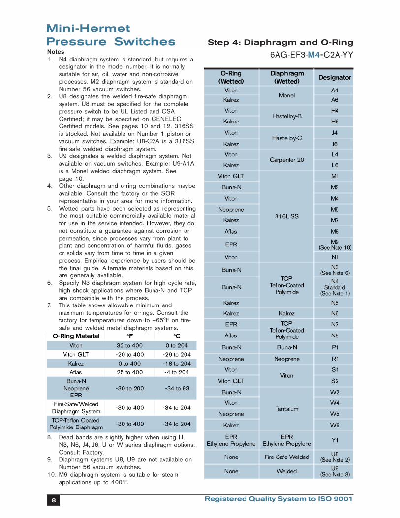
Notes1. N4 diaphragm system is standard, but requires a
designator in the model number. It is normallysuitable for air, oil, water and non-corrosiveprocesses. M2 diaphragm system is standard onNumber 56 vacuum switches.
2. U8 designates the welded fire-safe diaphragmsystem. U8 must be specified for the completepressure switch to be UL Listed and CSACertified; it may be specified on CENELECCertified models. See pages 10 and 12. 316SSis stocked. Not available on Number 1 piston orvacuum switches. Example: U8-C2A is a 316SSfire-safe welded diaphragm system.
3. U9 designates a welded diaphragm system. Notavailable on vacuum switches. Example: U9-A1Ais a Monel welded diaphragm system. Seepage 10.
4. Other diaphragm and o-ring combinations maybeavailable. Consult the factory or the SORrepresentative in your area for more information.
5. Wetted parts have been selected as representingthe most suitable commercially available materialfor use in the service intended. However, they donot constitute a guarantee against corrosion orpermeation, since processes vary from plant toplant and concentration of harmful fluids, gasesor solids vary from time to time in a givenprocess. Empirical experience by users should bethe final guide. Alternate materials based on thisare generally available.
6. Specify N3 diaphragm system for high cycle rate,high shock applications where Buna-N and TCPare compatible with the process.
7. This table shows allowable minimum andmaximum temperatures for o-rings. Consult thefactory for temperatures down to –65°F on fire-safe and welded metal diaphragm systems.
8. Dead bands are slightly higher when using H,N3, N6, J4, J6, U or W series diaphragm options.Consult Factory.
9. Diaphragm systems U8, U9 are not available onNumber 56 vacuum switches.
10. M9 diaphragm system is suitable for steamapplications up to 400oF.
Mini-HermetPressure Switches Step 4: Diaphragm and O-Ring
6AG-EF3-M4-C2A-YY
����������� �� ��
����� ������ �����
�������� ������ ��������
������ ���� ��������
����� ������ ������
�������������� !"
������� ���������
#����$���%&��'�'(���)��*+�$,���+
������ �������
-!� ������-����'!��,�+�'��(���)��*+
������ �������
������
������
�������
��������������
����������
��� �� �
����������������
�
��� �� ��
����������������
�
��� �� ��
������� ����� ���
�
��� �� ��
���������
�����
��
�!���" ��
����� �
"��� ��� �#
��� �� �$
%��� �&
'() �*�����������
����� "�
�!���"
��(��%���������+(����,�+�
"������������
�!���""
��� ���������������
��� �� "#
��� �� ��� �� "�
'() ��(��%���������+(����,�+�
"$
%��� "&
�!���" �!���" (�
"��� ��� "��� ��� )�
����������
�
��������� �
�!���"
������!,
-�
����� -
"��� ��� -#
��� �� -�
'()'�.������( �������
'()'�.������( �������
/�
"��� 0� �� �%��-��+�+1&
�����������
"��� -��+�+ 1*�����������

9Registered Quality System to ISO 9001
Mini-HermetPressure Switches Step 5: Pressure Port
6AG-EF3-M4-C2A-YY
������ *+�,+�-+�. ,*
�������/����������"�0�
�<=�98$�0 �<�=��98$�0 �<=�98$�0 �<=�98$�0 �<�=�98$�0
���B�#�) ''3 '�3�@��>�E���1/
1.�2"�������3
14� 15� <� <�
����) �"#3'���) ''3E���1/ /.� /4� /5� /.� /4�
���) �"#3'���) ''3E���1/
��� ��� ���
��#��3 �*�! ��@�*���-�"3�B"3" @��*�9�'����'�9��
�� '�"�3��#��9��!'����##'! "�#�)"�'
���,'# '����) �"#3'���) ''3
E���1/ �� �� ��
��� �) �"#3'��) ''3� �.����B�#
:�� :�� <�
5�����$)''�� '�0��3*������F'33�.
E���1/ �.� 6�� 6��
��� '33�@�5 ��� ��� ���
��� '33�@�� C�� C�� C��
��#'3 �.� �4� ���
Pre
ssur
e P
ort
Mat
eria
l
Notes1. Select designator for material and connection
size. Large bold face designators denote thoseitems generally available from stock. Small lightface designators denote items with limitedstock and possible long delivery.
2. 1/4” and 1/2” tapered BSP(F) pressure(designated B instead of A in the 3rdposition) ports are available.
3. The standard material and connection size forNumbers 6, 5, 9 & 1 pressure ports with:aluminum housing is F1A - 1/4” NPT(F) carbonsteel; stainless steel housing is C1A -1/4” NPT(F) 316SS.
4. Brass not available on Piston Numbers 9 and 1.
5. Other materials such as PVC, Kynar, etc., areavailable. Denote unlisted material byspecifying an X followed by the requiredconnection size, and describe the material.
Examples:X2A = PVC pressure port with 1/2” NPT(F)
connection.X1A = Titanium pressure port with
1/4” NPT(F) connection.
Non-metal pressure ports generally reduceproof pressure and may reduce overrangepressure. The pressure port material maylimit the process temperature. Delivery maybe longer than normal.
See next page for presentation of welded diaphragm and FM Approved fire-safe systems.

10 Registered Quality System to ISO 9001
Mini-HermetPressure Switches
Welded Diaphragm & Fire-Safe Systems
Designator Description
Fire-Safe Welded Diaphragm SystemFactory Mutual System Approved-U.S. Patent Number 4,438,305
Tested in flames at 1900oF for periods up to 30 minutes whilepressurized to the rated overrange pressure.
A metal diaphragm, the cylinder disc and the pressure port arewelded as a unit, thereby, eliminating the o-ring. Thisarrangement may be indicated for extremely corrosive, hot,harsh or volatile process where o-rings are not suitable. Seefire-safe definition on page 13.
316SS is standard. Hastelloy B and C, Monel and Titanium areavailable with possible longer lead times: The pressure portdesignator determines the material.Example: U8-C2A
U8 = Fire-safe welded diaphragm system C2A = 1/2” NPT(F) 316SS pressure port
Note1/2” NPT(F) is stocked; 1/4” NPT(F) is not stocked and has alonger lead time. Not available on Number 1 piston and vacuumswitches.
Welded Diaphragm System
A metal diaphragm is welded to the pressure port, thereby,eliminating the o-ring.
This arrangement may be indicated for extremely corrosive, hotor harsh process where o-rings are not suitable.
316SS is standard. Hastelloy B and C, Monel and Titanium areavailable with possible longer lead times: The pressure portdesignator determines the material.Example: U9-A2A
U9 = Welded diaphragm A2A = 1/2” NPT(F) Monel pressure port
NoteNot available on vacuum switches.
PistonShaft
SpringStop
CylinderDisc
Diaphragm
PressurePort
Diaphragm
PressurePort
U8
U9
ApprovedApprovedApprovedApprovedApproved

11Registered Quality System to ISO 9001
Mini-HermetPressure Switches Step 6 : Accessories
6AG-EF3-M4-C2A-YY
����������6������������������� ����������
E' '��,�� ����'�!3'�#'��*���"#��� �"�3��2@1'#��'�-"!'� 55
%#"-'���3� '�4"#�3�B�2(��<�=�98$�0�����))���2,3��"�#�,���*����� ����'� "*"'����2���&&��8(�8�(�8�� �5
%#"-'���3� '�4"#�3�B�2������2����$�0�����))���2,3��"�#�,���*����� ����'� "*"'����2���&&��8(�8�(�8�� �5��
%#"-'���3� '�4"#�3�B�2(��<�=�98$�0�����))���2,3��"�#�,���*������,,��-'�7��)���'� "*"'�� �8
G�!��4�,�� '! ���,3� '��D' �"#���"�,/��14�"#�,�'����'��." !/�"*���BH'! '�� ��-�!��4�1�'� '�� /�#���"#���1���� '�"�3�4� !/'�����'2!''���,�'����'�,�� �4� '�"�3��<���#�,"� �#����
��
��4,3"�#!'� �������D������� �
) �"#3'���� ''3�,"� �#��#��!@3"#�'���"�!�*���/"1/'���-'���#1'��#��,���*����#��3 �*�! ��@� 9�
9",'�$� �#!/"�#0�4��# "#1�I" �*���$���<�� ���=�,",'�0 9J
8�1(�*"B'���� �!/'��." /�,3�� "!�."�'� ��/���"#1��9�"# '��." /�!�� �4'���,'!"*"'�� �11"#1�"#*��4� "�#� 99
8�1(�� �"#3'���� ''3��� �!/'��." /�� �"#3'���� ''3�."�'� ��/���"#1��) �4,'��." /�!�� �4'���,'!"*"'� �11"#1�"#*��4� "�#��$��3"#'�(����!/���! '����#���,�!'��,'��3"#'�0
DD
�2,3��"�#�,���*��#��.'� /'� "1/ �'3'! �"!�3�H�#! "�#�B�2�." /��!�'.� '�4"#�3����<=�98$�0� �,(�3'* ����"1/ �!�#��" �!�##'! "�#������'A�"�'���% � "� '���#���)���'� "*"'���3����&(�����,���(�5(��(�67��3����&&(����,���(��(��7�6"-"�"�#���+����$8��/���"#1�0�&#!3��'��!�-'�����"#1�*���.'� /'� "1/ ��,,3"!� "�#���� �-�"3�B3'�." /�5�(�5�����C��/���"#1��
85
K-'��"�'�� �"#3'���� ''3�#�4',3� '�����',��� '�� �"#3'���� ''3� �1��9'�4�#'# 3@�� �!/'�� ��/���"#1�) �4,'��." /�!�� �4'���,'!"*"'�� �11"#1�"#*��4� "�#�
88
��#1"!"��3�-��#"�/����-'���'2 '�"����#��"# '�"���'2!', �.��I"#1�,�� �� GG
�,�2@�!�� "#1���2 '�"����#3@��9�3@�4"�'�',�2@�." /����))�,"14'# � FF
=>=�"����'���������**"2� �� /'�4��'3�#�4B'��*����,'!"�3��'A�"�'4'# ��#� �I'@'��'3�'./'�'�"#� /'�4��'3#�4B'��B@��#�=>=����!/�=>=�4�� �B'�!�4,3' '3@�"�'# "*"'��"#� /'� '2 ��*� /'����'�����"#A�"�@��E/'#�4��' /�#��#'�=>=�"���'A�"�'�(���'�=>=�*�33�.'��B@� /'�#�4B'���*���!/�" '4�������'2�4,3'(�=>��4'�#�� /�''�',��� '�� /'�."�'��#"�'# "*"�B3'��'A�"�'4'# ��
>

12 Registered Quality System to ISO 9001
Mini-HermetPressure Switches Agency Approval
The chart below shows authorized combinations of components so that the complete pressureswitch is approved, certified or listed by the cognizant agencies. Components or combinations ofthem may acquire additional approval, certification or listing prior to revision of this catalog.Contact the factory for the most current information.
UL Listed
CSACertified
JIS/RIISApproved
CENELECCertified
�� �� �� � � ���� � �� �� � �� �� ��� ����� �� ��� ������ ��� ��� ��� ��� ����� ������������� ���� �� � ��� �!
"����� #� ��� �� � ��� #$�� �%�� � ����&�� �� �� �%� �&#����&
"� �� �"� ��'� �� ���
���� ���� �� ���
#��
� ����� � �� �(���� � �
������������
�����������
��� ������� ������ �
������
������������������������������
��
��)�� �*��������� �!" �#��$%���&��$'#��("%�)$* #�*+�,��%"#�&!-'$�� ��(#$!!$'#��$* �."!'&��$'#�� #�/&� ��$* �+$�����$�%���"01+�*�$* �2$��%�$��(#&� ���!,�%$�&%���*"���0.�� �*+��3���$* �$!'��*����!,�%$�&%��*"���0.�� �*+��3��4
�� ��� � � � � ��� �� ��� � �� �� �� �� ������ �� �� ������ ��� ��� ��� ��� ����� ������������� ���� �� � ��� �!
"����� #� ��� �� � ��� #$�� �%�� � ����&�� �� �� �%� �&#����&
"� �� �"� ��'� �� ���
���� ���� �� ���
#��
� ����� � �� �(���� � �
������������
�����������
��� ������� ����� �
������
����5�������������������������
��
�� �� �� � � ���� � �� �� � �*�+�� �� � *��,���� ��� �"� �-� ��� �./
"����� #� ��� �� � ��� #$�� �%�� � ����&�� �� �� �%� �&#����&
"� �� �"� ��'� �� ���
���� ���� �� ���
#��
� ����� � �� �(���� � �
�������
�������������
�5��� ������� ������ �
�����������������
�������������������
��
����������
���6���6���6��6���67��6����������������������7��������������������8���8��8���8�����
6$��%�$#9��������:�������5��������;�)%�$ 9
��������������
�<
�� ����&&�0�� ���&���%� �� *�+� ��� � *���,�� ���� �./� �� ��)�1232�4� �2�5
"����� #� ��� �� � ��� #$�� �%�� � ����&�� �� �� �%� �&#����&
"� �� �"� ��'� �� ���
���� ���� �� ���
#��
� ����� � �� �(���� � �
���������������������
� ���5��� ������� ������ �
������
##
����5��5�6���������������
������������
�������������
���6���6���6��6���67��6����������������������7��������������������8���8��8���8�����
* Refer to Mini-Hermet Form 168 for special conditions for safe use.

13Registered Quality System to ISO 9001
Pressure SwitchA bi-stable electromechanical device thatactuates/deactuates one or more electricalswitching element(s) at a predetermineddiscrete pressure/vacuum (Set Point) uponrising or falling pressure/vacuum.
Adjustable RangeThe span of pressure between upper andlower limits within which the pressure switchcan be adjusted to actuate/deactuate. It isexpressed for increasing pressure.
Set PointThat discrete pressure at which the pressureswitch is adjusted to actuate/deactuate onrising or falling pressure. It must fall within theadjustable range and be called out asincreasing or decreasing pressure.
Dead BandThe difference in pressure between theincreasing Set Point and the decreasing SetPoint. It is expressed as typical, which is anaverage with the increasing Set Point at midrange for a pressure switch with the standardK switching element. It is normally fixed(non-adjustable).
OverrangeThe maximum input pressure that can becontinuously applied to the pressure switchwithout causing permanent change of SetPoint, leakage or material failure.
Proof PressureThe maximum input pressure that can becontinuously applied to the pressure switchwithout causing leakage or catastrophicmaterial failure. Permanent change of SetPoints may occur, or the device may berendered inoperative.
RepeatabilityThe ability of a pressure switch to successivelyoperate at a Set Point that is approached froma starting point in the same direction andreturns to the starting point over threeconsecutive cycles to establish a pressureprofile. Repeatability on SOR switches will besmaller than 1% of full scale per ISA/ANSIS51.1.
SPDT Switching ElementSingle-Pole, Double Throw (SPDT) has threeconnections: C — Common, NO — NormallyOpen and NC — Normally Closed, whichallows the switching element to be electricallyconnected to the circuit in either NO or NCstate.
DPDT Switching ElementDPDT is two synchronized SPDT switchingelements which actuate together at increasingSet Point and deactuate together atdecreasing Set Point. Discrete SPDT switchingelements allow two independent circuits to beswitched; i.e., one AC and one DC.
The synchronization linkage is factory set, andis not field adjustable. Synchronization isverified by connecting test lamps to theswitching elements and observing them go“On” simultaneously at actuation and “Off”simultaneously at deactuation.
Fire-SafeThe ability of a welded seal pressure sensor tocontain the process at elevated temperaturesup to 1200oF at the rated overrange pressure,unsupported by the body of the pressureswitch.
Hermetically SealedA welded steel capsule with glass-to-metal,factory-sealed, electrical leads that isolates theelectrical switching element(s) from theenvironment.
SOR recognizes that there is no industry convention with respect to terminology and definitionspertinent to pressure switches. This glossary applies to SOR pressure with hermetically switchingelement capsules.
Mini-HermetPressure Switches Glossary of Terms
14 Registered Quality System to ISO 9001
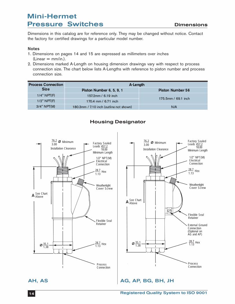
Mini-HermetPressure SwitchesDimensions in this catalog are for reference only. They may be changed without notice. Contactthe factory for certified drawings for a particular model number.
Notes1. Dimensions on pages 14 and 15 are expressed as millimeters over inches
(Linear = mm/in.).2. Dimensions marked A-Length on housing dimension drawings vary with respect to process
connection size. The chart below lists A-Lengths with reference to piston number and processconnection size.
��������/���������"�0�
�!7����(
������������*+�,+�-+�. ������������,*
�<=�98$�0 �����44�<������"#!/�����44�<������"#!/
�<�=�98$�0 �����44�<������"#!/
�<=�98$�0 �����44�<������"#!/�$�� 3"#'�#� ��/�.#0 <�
Housing Designator
76.23.00
∅∅∅∅∅ Minimum
Installation Clearance
Factory SealedLeads 457.2 18.00Minimum Length
1/2” NPT(M)ElectricalConnection
28.7 Hex1.13
WeathertightCover Screw
Flexible SealRetainer External Ground
Connection(Optional onAG and AP)
28.7 Hex1.13∅∅∅∅∅ 35.1
1.38
See ChartAboveA
∅∅∅∅∅ Minimum
Installation Clearance
76.23.00
Factory SealedLeads 457.2 18.00Minimum Length
1/2” NPT(M)ElectricalConnection
28.7 Hex1.13
WeathertightCover Screw
Flexible SealRetainer
28.7 Hex1.13
ProcessConnection
ProcessConnection
Dimensions
See ChartAboveA
AH, AS AG, AP, BG, BH, JH
∅∅∅∅∅ 35.11.38

15Registered Quality System to ISO 9001
Mini-HermetPressure Switches Dimensions
/������� ���������� 8���(��2��3 29��3
����"#1 ��(��9(�5� ��� �����
����"#1 ��(��)(�5�(�C� ��� �����
C�#! "�#�5�2 85$���� ��/���"#10
��������
9",'����# "#1�J" 9J$���� ��/���"#10
��������
8'�4"#�3�5�2 �5(��5��(��8$���� ��/���"#10
��������
Pipe Mounting Bracket - PK Junction Box with TerminalBlock - TB
Terminal Boxes - H Series
Switch Mounting Holes(Typical 4)
Holes for 5/16”Diameter MountingHardware.Furnished withU-Bolts forMounting to 1-1/2”to 2” Pipe.
PressurePort Side
Pipe(Reference)
C SwitchMounting HolesL
Parallel MountingPerpendicular Mounting
133.45.25
50.82.00
40.51.59
7.40.29
95.33.75
71.42.81
11.90.47
31.01.22
71.42.81
141.25.56 70.6
2.78(Typical)
7.9 Diameter0.31 (2 Places)
93.73.69 22.4
0.889.9
0.39
*135.76.05
78.53.09
(Typical)
3/4” NPT(F)Electrical
Connection(3 Places)
1/2” NPT(F)Instrument Connection
*Dimension shown is approximate and based on a 5-thread engangement.
HT and HB: 1/2” NPT(F)
HBME: M20 x 1.5(F)
HT and HB:1/2” NPT(F)HBME:M20 x 1.5(F)
108.04.25
Instrument Connection
Remove Cover for ScrewTerminal Access
Cover Locking Screw54.02.13
69.92.75
89.43.52
58.62.31
43.61.72
2.40.09
Dimensions Shown are forReference Only. Contact theFactory for Certified DimensionDrawings.
Linear = mm/in.
Approximate Shipping Weight
16 Registered Quality System to ISO 9001
Process Instrumentation
SOR INC.14685 West 105th StreetLenexa, Kansas 66215
Phone 913-888-2630Toll Free 800-676-6794Fax 913-888-0767
www.sorinc.com
Registered Quality System to ISO 9001 Form 456 (02.02) Printed in U.S.A.