Mini CORI -FLOW - Bronkhorst
49
Doc. no.: 9.17.050K Date: 23-07-2018 ATTENTION Please read this Instruction Manual carefully before installing and operating the instrument. Not following the guidelines could result in personal injury and/or damage to the equipment. mini CORI-FLOW™ M1x series Compact Coriolis Mass Flow Meters/Controllers for Liquids and Gases Instruction Manual
Transcript of Mini CORI -FLOW - Bronkhorst
Doc. no.: 9.17.050K Date: 23-07-2018
ATTENTIONPlease read this Instruction Manual carefully before installing and operating the instrument.
Not following the guidelines could result in personal injury and/or damage to the equipment.
mini CORI-FLOW™ M1x seriesCompact Coriolis Mass Flow
Meters/Controllers for Liquids and Gases
Instruction Manual
Bronkhorst®
Instruction Manual mini CORI-FLOW™ M1x 9.17.050K2
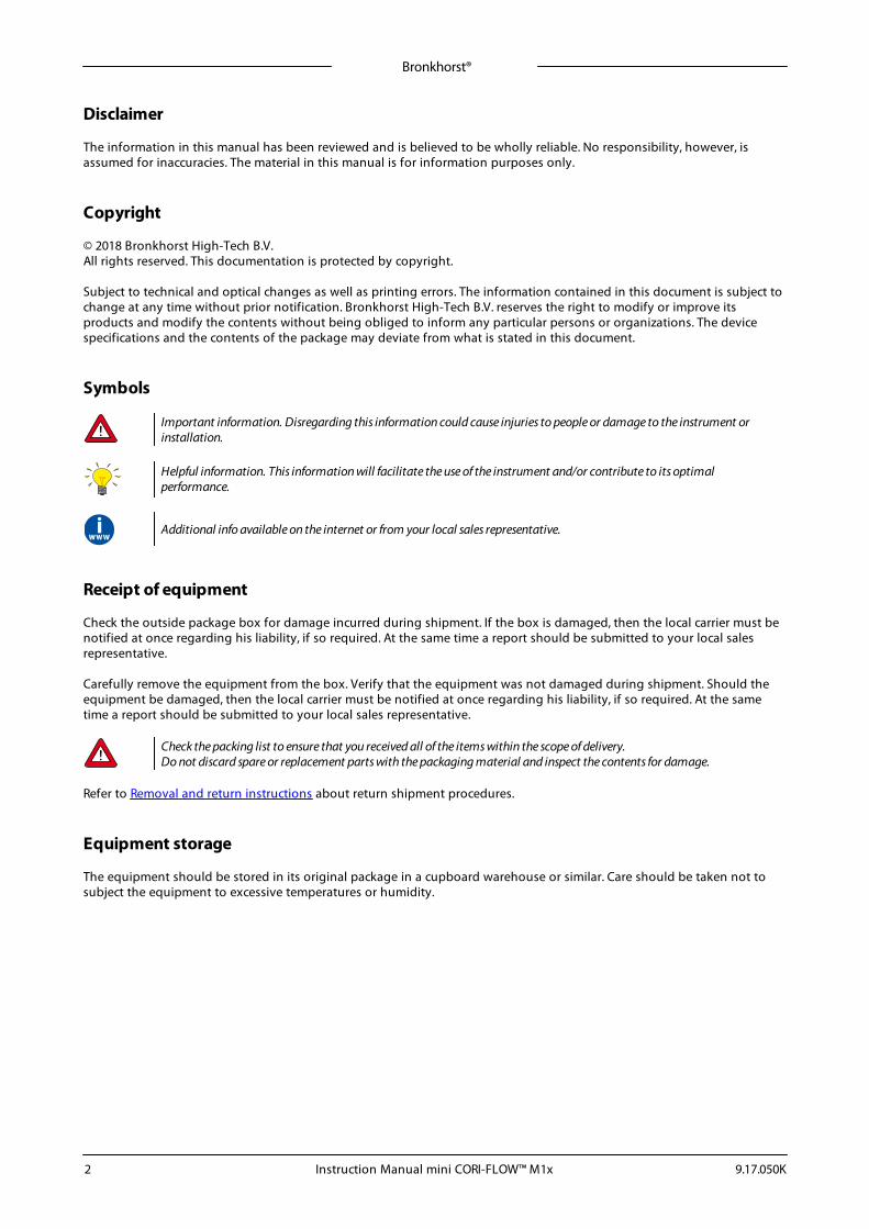
Disclaimer
The information in this manual has been reviewed and is believed to be wholly reliable. No responsibility, however, isassumed for inaccuracies. The material in this manual is for information purposes only.
Copyright
© 2018 Bronkhorst High-Tech B.V.All rights reserved. This documentation is protected by copyright.
Subject to technical and optical changes as well as printing errors. The information contained in this document is subject tochange at any time without prior notification. Bronkhorst High-Tech B.V. reserves the right to modify or improve itsproducts and modify the contents without being obliged to inform any particular persons or organizations. The devicespecifications and the contents of the package may deviate from what is stated in this document.
Symbols
Important information. Disregarding this information could cause injuries to people or damage to the instrument orinstallation.
Helpful information. This information will facilitate the use of the instrument and/or contribute to its optimalperformance.
Additional info available on the internet or from your local sales representative.
Receipt of equipment
Check the outside package box for damage incurred during shipment. If the box is damaged, then the local carrier must benotified at once regarding his liability, if so required. At the same time a report should be submitted to your local salesrepresentative.
Carefully remove the equipment from the box. Verify that the equipment was not damaged during shipment. Should theequipment be damaged, then the local carrier must be notified at once regarding his liability, if so required. At the sametime a report should be submitted to your local sales representative.
Check the packing list to ensure that you received all of the items within the scope of delivery.Do not discard spare or replacement parts with the packaging material and inspect the contents for damage.
Refer to Removal and return instructions about return shipment procedures.
Equipment storage
The equipment should be stored in its original package in a cupboard warehouse or similar. Care should be taken not tosubject the equipment to excessive temperatures or humidity.
Bronkhorst®
Instruction Manual mini CORI-FLOW™ M1x9.17.050K 3
Warranty
Bronkhorst® products are warranted against defects in material and workmanship for a period of three years from the dateof shipment, provided they are used in accordance with the ordering specifications and not subject to abuse or physicaldamage. Products that do not operate properly during this period may be repaired or replaced at no charge. Repairs arenormally warranted for one year or the balance of the original warranty, whichever is the longer.
See also section 9 (Guarantee) of the Conditions of sales:www.bronkhorst.com/about/conditions-of-sales/
The warranty includes all initial and latent defects, random failures, and indeterminable internal causes.
It excludes failures and damage caused by the customer, such as contamination, improper electrical hook-up, physical shocketc.
Re-conditioning of products primarily returned for warranty service that is partly or wholly judged non-warranty may becharged for.
Bronkhorst High-Tech B.V. or affiliated company prepays outgoing freight charges when any part of the service isperformed under warranty, unless otherwise agreed upon beforehand, however, if the product has been returned collect toour factory or service center, these costs are added to the repair invoice. Import and/or export charges, foreign shippingmethods/carriers are paid by the customer.
General safety precautions
This product is intended for use by qualified personnel who recognize shock hazards and are familiar with the safetyprecautions required to avoid possible injury. Read the operating information carefully before using the product.
Before operating, make sure the line cord is connected to a properly grounded power receptacle. Inspect the connectingcables for cracks or breaks before each use.
The equipment and accessories must be used in accordance with their specifications and operating instructions, otherwisethe safety of the equipment may be impaired.
If required, replace fuses with the same type and rating for continued protection against fire hazard.
Opening the equipment is not allowed. There are no repairable parts inside. In case of a defect please return the equipmentto Bronkhorst High-Tech B.V.
One or more warning signs may be present on different parts of the product. These signs have the following meaning:
Consult the instruction manual for handling instructions
Surface may get hot during operation
Shock hazard; electrical parts inside
To maintain protection from electric shock and fire, replacement components must be obtained from Bronkhorst. Standardfuses, with applicable national safety approvals, may be used if the rating and type are the same. Other components that arenot safety related may be obtained from other suppliers, as long as they are equivalent to the original component. Selectedparts should be obtained only through Bronkhorst, to maintain accuracy and functionality of the product. If you are unsureabout the relevance of a replacement component, contact Bronkhorst for information.

Bronkhorst®
Instruction Manual mini CORI-FLOW™ M1x 9.17.050K4
Bronkhorst®
Instruction Manual mini CORI-FLOW™ M1x9.17.050K 5
Table of contents
. . . . . . . . . . . . . . . . . . . . . . . . . . . . . . . . . . . . . . . . . . . . . . . . . . . . . . . . . . . . . . . . . . . . . . . . . . . . . . . . . . . . . . . . . . . . . . . . . . . . . . . . . . . . 7Introduction 1. . . . . . . . . . . . . . . . . . . . . . . . . . . . . . . . . . . . . . . . . . . . . . . . . . . . . . . . . . . . . . . . . . . . . . . . . . . . . . . . . . . . . . . . . . . . . . . . . . . . . . . . . . . . 71.1 Scope of this manual
. . . . . . . . . . . . . . . . . . . . . . . . . . . . . . . . . . . . . . . . . . . . . . . . . . . . . . . . . . . . . . . . . . . . . . . . . . . . . . . . . . . . . . . . . . . . . . . . . . . . . . . . . . . . 71.2 Intended use
. . . . . . . . . . . . . . . . . . . . . . . . . . . . . . . . . . . . . . . . . . . . . . . . . . . . . . . . . . . . . . . . . . . . . . . . . . . . . . . . . . . . . . . . . . . . . . . . . . . . . . . . . . . . 71.3 Product description
. . . . . . . . . . . . . . . . . . . . . . . . . . . . . . . . . . . . . . . . . . . . . . . . . . . . . . . . . . . . . . . . . . . . . . . . . . . . . . . . . . . . . . . . . . . . . . . . . . . . . . . . . . . . 81.4 Product overview
. . . . . . . . . . . . . . . . . . . . . . . . . . . . . . . . . . . . . . . . . . . . . . . . . . . . . . . . . . . . . . . . . . . . . . . . . . . . . . . . . . . . . . . . . . . . . . . . . . . . . . . . . . . . 81.5 Calibration
. . . . . . . . . . . . . . . . . . . . . . . . . . . . . . . . . . . . . . . . . . . . . . . . . . . . . . . . . . . . . . . . . . . . . . . . . . . . . . . . . . . . . . . . . . . . . . . . . . . . . . . . . . . . 91.6 Maintenance
. . . . . . . . . . . . . . . . . . . . . . . . . . . . . . . . . . . . . . . . . . . . . . . . . . . . . . . . . . . . . . . . . . . . . . . . . . . . . . . . . . . . . . . . . . . . . . . . . . . . . . . . . . . . 91.7 Documentation
. . . . . . . . . . . . . . . . . . . . . . . . . . . . . . . . . . . . . . . . . . . . . . . . . . . . . . . . . . . . . . . . . . . . . . . . . . . . . . . . . . . . . . . . . . . . . . . . . . . . . . . . . . . . 101.8 Model key
. . . . . . . . . . . . . . . . . . . . . . . . . . . . . . . . . . . . . . . . . . . . . . . . . . . . . . . . . . . . . . . . . . . . . . . . . . . . . . . . . . . . . . . . . . . . . . . . . . . . . . . . . . . . 11Installation 2. . . . . . . . . . . . . . . . . . . . . . . . . . . . . . . . . . . . . . . . . . . . . . . . . . . . . . . . . . . . . . . . . . . . . . . . . . . . . . . . . . . . . . . . . . . . . . . . . . . . . . . . . . . . 112.1 Functional properties
. . . . . . . . . . . . . . . . . . . . . . . . . . . . . . . . . . . . . . . . . . . . . . . . . . . . . . . . . . . . . . . . . . . . . . . . . . . . . . . . . . . . . . . . . . . . . . . . . . . . . . . . . . . . 112.2 Operating conditions
. . . . . . . . . . . . . . . . . . . . . . . . . . . . . . . . . . . . . . . . . . . . . . . . . . . . . . . . . . . . . . . . . . . . . . . . . . . . . . . . . . . . . . . . . . . . . . . . . . . . . . . . . . . . 112.3 Mounting
. . . . . . . . . . . . . . . . . . . . . . . . . . . . . . . . . . . . . . . . . . . . . . . . . . . . . . . . . . . . . . . . . . . . . . . . . . . . . . . . . . . . . . . . . . . . . . . . . . . . . . . . . . . . 11Orientation 2.3.1
. . . . . . . . . . . . . . . . . . . . . . . . . . . . . . . . . . . . . . . . . . . . . . . . . . . . . . . . . . . . . . . . . . . . . . . . . . . . . . . . . . . . . . . . . . . . . . . . . . . . . . . . . . . . 12Location 2.3.2
. . . . . . . . . . . . . . . . . . . . . . . . . . . . . . . . . . . . . . . . . . . . . . . . . . . . . . . . . . . . . . . . . . . . . . . . . . . . . . . . . . . . . . . . . . . . . . . . . . . . . . . . . . . . 12Preventing resonance 2.3.3
. . . . . . . . . . . . . . . . . . . . . . . . . . . . . . . . . . . . . . . . . . . . . . . . . . . . . . . . . . . . . . . . . . . . . . . . . . . . . . . . . . . . . . . . . . . . . . . . . . . . . . . . . . . . 12Fluidic connections 2.3.4
. . . . . . . . . . . . . . . . . . . . . . . . . . . . . . . . . . . . . . . . . . . . . . . . . . . . . . . . . . . . . . . . . . . . . . . . . . . . . . . . . . . . . . . . . . . . . . . . . . . . . . . . . . . . 13Piping requirements 2.3.5
. . . . . . . . . . . . . . . . . . . . . . . . . . . . . . . . . . . . . . . . . . . . . . . . . . . . . . . . . . . . . . . . . . . . . . . . . . . . . . . . . . . . . . . . . . . . . . . . . . . . . . . . . . . . 132.4 Preventing pressure shocks
. . . . . . . . . . . . . . . . . . . . . . . . . . . . . . . . . . . . . . . . . . . . . . . . . . . . . . . . . . . . . . . . . . . . . . . . . . . . . . . . . . . . . . . . . . . . . . . . . . . . . . . . . . . . 132.5 Preventing hydraulic shocks
. . . . . . . . . . . . . . . . . . . . . . . . . . . . . . . . . . . . . . . . . . . . . . . . . . . . . . . . . . . . . . . . . . . . . . . . . . . . . . . . . . . . . . . . . . . . . . . . . . . . . . . . . . . . 142.6 Electrical connection
. . . . . . . . . . . . . . . . . . . . . . . . . . . . . . . . . . . . . . . . . . . . . . . . . . . . . . . . . . . . . . . . . . . . . . . . . . . . . . . . . . . . . . . . . . . . . . . . . . . . . . . . . . . . 14Analog or local connection 2.6.1
. . . . . . . . . . . . . . . . . . . . . . . . . . . . . . . . . . . . . . . . . . . . . . . . . . . . . . . . . . . . . . . . . . . . . . . . . . . . . . . . . . . . . . . . . . . . . . . . . . . . . . . . . . . . 14Digital RS232 connection 2.6.2
. . . . . . . . . . . . . . . . . . . . . . . . . . . . . . . . . . . . . . . . . . . . . . . . . . . . . . . . . . . . . . . . . . . . . . . . . . . . . . . . . . . . . . . . . . . . . . . . . . . . . . . . . . . . 15Digital RS485 connection (fieldbus) 2.6.3
. . . . . . . . . . . . . . . . . . . . . . . . . . . . . . . . . . . . . . . . . . . . . . . . . . . . . . . . . . . . . . . . . . . . . . . . . . . . . . . . . . . . . . . . . . . . . . . . . . . . . . . . . . . . 15FLOW-BUS 2.6.3.1
. . . . . . . . . . . . . . . . . . . . . . . . . . . . . . . . . . . . . . . . . . . . . . . . . . . . . . . . . . . . . . . . . . . . . . . . . . . . . . . . . . . . . . . . . . . . . . . . . . . . . . . . . . . . 16Modbus 2.6.3.2
. . . . . . . . . . . . . . . . . . . . . . . . . . . . . . . . . . . . . . . . . . . . . . . . . . . . . . . . . . . . . . . . . . . . . . . . . . . . . . . . . . . . . . . . . . . . . . . . . . . . . . . . . . . . 16PROFIBUS DP 2.6.3.3
. . . . . . . . . . . . . . . . . . . . . . . . . . . . . . . . . . . . . . . . . . . . . . . . . . . . . . . . . . . . . . . . . . . . . . . . . . . . . . . . . . . . . . . . . . . . . . . . . . . . . . . . . . . . 16DeviceNet™ 2.6.3.4
. . . . . . . . . . . . . . . . . . . . . . . . . . . . . . . . . . . . . . . . . . . . . . . . . . . . . . . . . . . . . . . . . . . . . . . . . . . . . . . . . . . . . . . . . . . . . . . . . . . . . . . . . . . . 17Operation 3. . . . . . . . . . . . . . . . . . . . . . . . . . . . . . . . . . . . . . . . . . . . . . . . . . . . . . . . . . . . . . . . . . . . . . . . . . . . . . . . . . . . . . . . . . . . . . . . . . . . . . . . . . . . 173.1 Powering up and powering down
. . . . . . . . . . . . . . . . . . . . . . . . . . . . . . . . . . . . . . . . . . . . . . . . . . . . . . . . . . . . . . . . . . . . . . . . . . . . . . . . . . . . . . . . . . . . . . . . . . . . . . . . . . . . 173.2 First use
. . . . . . . . . . . . . . . . . . . . . . . . . . . . . . . . . . . . . . . . . . . . . . . . . . . . . . . . . . . . . . . . . . . . . . . . . . . . . . . . . . . . . . . . . . . . . . . . . . . . . . . . . . . . 173.3 Valve Safe State
. . . . . . . . . . . . . . . . . . . . . . . . . . . . . . . . . . . . . . . . . . . . . . . . . . . . . . . . . . . . . . . . . . . . . . . . . . . . . . . . . . . . . . . . . . . . . . . . . . . . . . . . . . . . 173.4 Mass flow measurement and control
. . . . . . . . . . . . . . . . . . . . . . . . . . . . . . . . . . . . . . . . . . . . . . . . . . . . . . . . . . . . . . . . . . . . . . . . . . . . . . . . . . . . . . . . . . . . . . . . . . . . . . . . . . . . 183.5 Temperature considerations
. . . . . . . . . . . . . . . . . . . . . . . . . . . . . . . . . . . . . . . . . . . . . . . . . . . . . . . . . . . . . . . . . . . . . . . . . . . . . . . . . . . . . . . . . . . . . . . . . . . . . . . . . . . . 193.6 Manual controls
. . . . . . . . . . . . . . . . . . . . . . . . . . . . . . . . . . . . . . . . . . . . . . . . . . . . . . . . . . . . . . . . . . . . . . . . . . . . . . . . . . . . . . . . . . . . . . . . . . . . . . . . . . . . 19LED indications 3.6.1
. . . . . . . . . . . . . . . . . . . . . . . . . . . . . . . . . . . . . . . . . . . . . . . . . . . . . . . . . . . . . . . . . . . . . . . . . . . . . . . . . . . . . . . . . . . . . . . . . . . . . . . . . . . . 20Multifunctional switch 3.6.2
. . . . . . . . . . . . . . . . . . . . . . . . . . . . . . . . . . . . . . . . . . . . . . . . . . . . . . . . . . . . . . . . . . . . . . . . . . . . . . . . . . . . . . . . . . . . . . . . . . . . . . . . . . . . 20Normal operating functions 3.6.2.1
. . . . . . . . . . . . . . . . . . . . . . . . . . . . . . . . . . . . . . . . . . . . . . . . . . . . . . . . . . . . . . . . . . . . . . . . . . . . . . . . . . . . . . . . . . . . . . . . . . . . . . . . . . . . 21Power-up functions 3.6.2.2
. . . . . . . . . . . . . . . . . . . . . . . . . . . . . . . . . . . . . . . . . . . . . . . . . . . . . . . . . . . . . . . . . . . . . . . . . . . . . . . . . . . . . . . . . . . . . . . . . . . . . . . . . . . . 21Control mode - readout/change 3.6.2.3
. . . . . . . . . . . . . . . . . . . . . . . . . . . . . . . . . . . . . . . . . . . . . . . . . . . . . . . . . . . . . . . . . . . . . . . . . . . . . . . . . . . . . . . . . . . . . . . . . . . . . . . . . . . . 22Network settings - readout/change 3.6.2.4
. . . . . . . . . . . . . . . . . . . . . . . . . . . . . . . . . . . . . . . . . . . . . . . . . . . . . . . . . . . . . . . . . . . . . . . . . . . . . . . . . . . . . . . . . . . . . . . . . . . . . . . . . . . . 233.7 Communication modes
. . . . . . . . . . . . . . . . . . . . . . . . . . . . . . . . . . . . . . . . . . . . . . . . . . . . . . . . . . . . . . . . . . . . . . . . . . . . . . . . . . . . . . . . . . . . . . . . . . . . . . . . . . . . 24Analog operation 3.7.1
. . . . . . . . . . . . . . . . . . . . . . . . . . . . . . . . . . . . . . . . . . . . . . . . . . . . . . . . . . . . . . . . . . . . . . . . . . . . . . . . . . . . . . . . . . . . . . . . . . . . . . . . . . . . 24Digital RS232 operation 3.7.2
. . . . . . . . . . . . . . . . . . . . . . . . . . . . . . . . . . . . . . . . . . . . . . . . . . . . . . . . . . . . . . . . . . . . . . . . . . . . . . . . . . . . . . . . . . . . . . . . . . . . . . . . . . . . 24FlowDDE 3.7.2.1
. . . . . . . . . . . . . . . . . . . . . . . . . . . . . . . . . . . . . . . . . . . . . . . . . . . . . . . . . . . . . . . . . . . . . . . . . . . . . . . . . . . . . . . . . . . . . . . . . . . . . . . . . . . . 25Software (DDE applications) 3.7.2.2
Bronkhorst®
Instruction Manual mini CORI-FLOW™ M1x 9.17.050K6
. . . . . . . . . . . . . . . . . . . . . . . . . . . . . . . . . . . . . . . . . . . . . . . . . . . . . . . . . . . . . . . . . . . . . . . . . . . . . . . . . . . . . . . . . . . . . . . . . . . . . . . . . . . . 25Fieldbus operation 3.7.3
. . . . . . . . . . . . . . . . . . . . . . . . . . . . . . . . . . . . . . . . . . . . . . . . . . . . . . . . . . . . . . . . . . . . . . . . . . . . . . . . . . . . . . . . . . . . . . . . . . . . . . . . . . . . 263.8 Adjusting zero point
. . . . . . . . . . . . . . . . . . . . . . . . . . . . . . . . . . . . . . . . . . . . . . . . . . . . . . . . . . . . . . . . . . . . . . . . . . . . . . . . . . . . . . . . . . . . . . . . . . . . . . . . . . . . 27Manual procedure 3.8.1
. . . . . . . . . . . . . . . . . . . . . . . . . . . . . . . . . . . . . . . . . . . . . . . . . . . . . . . . . . . . . . . . . . . . . . . . . . . . . . . . . . . . . . . . . . . . . . . . . . . . . . . . . . . . 27Digital procedure 3.8.2
. . . . . . . . . . . . . . . . . . . . . . . . . . . . . . . . . . . . . . . . . . . . . . . . . . . . . . . . . . . . . . . . . . . . . . . . . . . . . . . . . . . . . . . . . . . . . . . . . . . . . . . . . . . . 273.9 Checking calibration status
. . . . . . . . . . . . . . . . . . . . . . . . . . . . . . . . . . . . . . . . . . . . . . . . . . . . . . . . . . . . . . . . . . . . . . . . . . . . . . . . . . . . . . . . . . . . . . . . . . . . . . . . . . . . 283.10 Disabling multifunctional switch
. . . . . . . . . . . . . . . . . . . . . . . . . . . . . . . . . . . . . . . . . . . . . . . . . . . . . . . . . . . . . . . . . . . . . . . . . . . . . . . . . . . . . . . . . . . . . . . . . . . . . . . . . . . . 29Digital parameters 4. . . . . . . . . . . . . . . . . . . . . . . . . . . . . . . . . . . . . . . . . . . . . . . . . . . . . . . . . . . . . . . . . . . . . . . . . . . . . . . . . . . . . . . . . . . . . . . . . . . . . . . . . . . . 304.1 Measurement and control
. . . . . . . . . . . . . . . . . . . . . . . . . . . . . . . . . . . . . . . . . . . . . . . . . . . . . . . . . . . . . . . . . . . . . . . . . . . . . . . . . . . . . . . . . . . . . . . . . . . . . . . . . . . . 30Advanced measurement and control 4.1.1
. . . . . . . . . . . . . . . . . . . . . . . . . . . . . . . . . . . . . . . . . . . . . . . . . . . . . . . . . . . . . . . . . . . . . . . . . . . . . . . . . . . . . . . . . . . . . . . . . . . . . . . . . . . . 324.2 Alarms
. . . . . . . . . . . . . . . . . . . . . . . . . . . . . . . . . . . . . . . . . . . . . . . . . . . . . . . . . . . . . . . . . . . . . . . . . . . . . . . . . . . . . . . . . . . . . . . . . . . . . . . . . . . . 344.3 Counter
. . . . . . . . . . . . . . . . . . . . . . . . . . . . . . . . . . . . . . . . . . . . . . . . . . . . . . . . . . . . . . . . . . . . . . . . . . . . . . . . . . . . . . . . . . . . . . . . . . . . . . . . . . . . 354.4 Network configuration
. . . . . . . . . . . . . . . . . . . . . . . . . . . . . . . . . . . . . . . . . . . . . . . . . . . . . . . . . . . . . . . . . . . . . . . . . . . . . . . . . . . . . . . . . . . . . . . . . . . . . . . . . . . . 364.5 Fluid set
. . . . . . . . . . . . . . . . . . . . . . . . . . . . . . . . . . . . . . . . . . . . . . . . . . . . . . . . . . . . . . . . . . . . . . . . . . . . . . . . . . . . . . . . . . . . . . . . . . . . . . . . . . . . 38Advanced fluid set parameters 4.5.1
. . . . . . . . . . . . . . . . . . . . . . . . . . . . . . . . . . . . . . . . . . . . . . . . . . . . . . . . . . . . . . . . . . . . . . . . . . . . . . . . . . . . . . . . . . . . . . . . . . . . . . . . . . . . 384.6 Controller
. . . . . . . . . . . . . . . . . . . . . . . . . . . . . . . . . . . . . . . . . . . . . . . . . . . . . . . . . . . . . . . . . . . . . . . . . . . . . . . . . . . . . . . . . . . . . . . . . . . . . . . . . . . . 404.7 Master/slave configuration (FLOW-BUS)
. . . . . . . . . . . . . . . . . . . . . . . . . . . . . . . . . . . . . . . . . . . . . . . . . . . . . . . . . . . . . . . . . . . . . . . . . . . . . . . . . . . . . . . . . . . . . . . . . . . . . . . . . . . . 414.8 Device identification
. . . . . . . . . . . . . . . . . . . . . . . . . . . . . . . . . . . . . . . . . . . . . . . . . . . . . . . . . . . . . . . . . . . . . . . . . . . . . . . . . . . . . . . . . . . . . . . . . . . . . . . . . . . . 424.9 Special parameters
. . . . . . . . . . . . . . . . . . . . . . . . . . . . . . . . . . . . . . . . . . . . . . . . . . . . . . . . . . . . . . . . . . . . . . . . . . . . . . . . . . . . . . . . . . . . . . . . . . . . . . . . . . . . 43Default control mode 4.9.1
. . . . . . . . . . . . . . . . . . . . . . . . . . . . . . . . . . . . . . . . . . . . . . . . . . . . . . . . . . . . . . . . . . . . . . . . . . . . . . . . . . . . . . . . . . . . . . . . . . . . . . . . . . . . 44Troubleshooting and service 5. . . . . . . . . . . . . . . . . . . . . . . . . . . . . . . . . . . . . . . . . . . . . . . . . . . . . . . . . . . . . . . . . . . . . . . . . . . . . . . . . . . . . . . . . . . . . . . . . . . . . . . . . . . . 445.1 Errors and warnings
. . . . . . . . . . . . . . . . . . . . . . . . . . . . . . . . . . . . . . . . . . . . . . . . . . . . . . . . . . . . . . . . . . . . . . . . . . . . . . . . . . . . . . . . . . . . . . . . . . . . . . . . . . . . 445.2 Restoring factory settings
. . . . . . . . . . . . . . . . . . . . . . . . . . . . . . . . . . . . . . . . . . . . . . . . . . . . . . . . . . . . . . . . . . . . . . . . . . . . . . . . . . . . . . . . . . . . . . . . . . . . . . . . . . . . 445.3 Common issues
. . . . . . . . . . . . . . . . . . . . . . . . . . . . . . . . . . . . . . . . . . . . . . . . . . . . . . . . . . . . . . . . . . . . . . . . . . . . . . . . . . . . . . . . . . . . . . . . . . . . . . . . . . . . 475.4 Service
. . . . . . . . . . . . . . . . . . . . . . . . . . . . . . . . . . . . . . . . . . . . . . . . . . . . . . . . . . . . . . . . . . . . . . . . . . . . . . . . . . . . . . . . . . . . . . . . . . . . . . . . . . . . 48Returns 6. . . . . . . . . . . . . . . . . . . . . . . . . . . . . . . . . . . . . . . . . . . . . . . . . . . . . . . . . . . . . . . . . . . . . . . . . . . . . . . . . . . . . . . . . . . . . . . . . . . . . . . . . . . . 486.1 Removal and return instructions
. . . . . . . . . . . . . . . . . . . . . . . . . . . . . . . . . . . . . . . . . . . . . . . . . . . . . . . . . . . . . . . . . . . . . . . . . . . . . . . . . . . . . . . . . . . . . . . . . . . . . . . . . . . . 486.2 Disposal (end of lifetime)

Bronkhorst®
Instruction Manual mini CORI-FLOW™ M1x9.17.050K 7
1 Introduction
1.1 Scope of this manualThis manual contains general product information, installation and operating instructions and troubleshooting tips for the mini CORI-FLOW™ M1x series mass flow meters and controllers for liquids and gases.
1.2 Intended use
The Bronkhorst® mini CORI-FLOW™ M1x is an accurate mass-flow meter/controller for measuring and controlling gas andliquid flows at pressures up to 200 bar(a), virtually independent of pressure and temperature changes. A wide range ofliquids and gases can be measured independent of fluid density, temperature and viscosity.
The end user is considered to be familiar with the necessary safety precautions, and to comply with the appropriateprotective measures as described in the Material Safety Data Sheets of the media to be used in the system (if applicable).
The wetted materials incorporated in the mini CORI-FLOW are compatible with media and conditions (e.g. pressure,temperature) as specified at ordering time. If you are planning to use the product (including any third party componentssupplied by Bronkhorst, such as pumps or valves) with other media and/or other conditions, always be sure to check thewetted materials (including seals) for compatibility. See the technical specifications of the product and consult third partydocumentation (if applicable) to check the incorporated materials.
Responsibility for the use of the equipment with regard to suitability, intended use, cleaning and corrosion resistance of theused materials against the applied media lies solely with the end user. Bronkhorst High-Tech B.V. cannot be held liable forany damage resulting from improper use, use for other than the intended purpose or use of other media and/or conditionsthan specified on the purchase order.
1.3 Product description
mini CORI-FLOW™ M1x instruments are precise and compact mass flow meters and controllers for liquids and gases, basedon the Coriolis measuring principle. Designed to cover the needs of the low flow market, there are 4 models, supportingflow ranges from 5 g/h up to 300 kg/h (full scale values), each offering multi-range functionality: factory calibratedmeasuring ranges can be re-scaled by the user, without affecting the original accuracy specifications. The instruments arebuilt into a robust, weatherproof housing, with a high ingress protection rating.
The mini CORI-FLOW measures real mass flow, regardless of the media properties. The system can be complemented with a(modular or integrated) control valve or a pump and a readout and control unit to measure and control gas and liquidflows.
Measuring principleInstruments of the mini CORI-FLOW series contain a uniquely shaped, single loop sensor tube, forming part of anoscillating system. When a fluid flows through the tube, the Coriolis force causes a phase shift, which is detected by sensorsand fed into the integrated printed circuit board. The resulting output signal is proportional to the real mass flow rate,independent of fluid density, temperature, viscosity, pressure, heat capacity or conductivity. Coriolis mass flow
Bronkhorst®
Instruction Manual mini CORI-FLOW™ M1x 9.17.050K8
measurement is fast, accurate and inherently bi-directional. The mini CORI-FLOW™ M1x features density and temperature ofthe fluid as secondary outputs.
Multi-rangeThe mini CORI-FLOW offers multi-range functionality: factory calibrated ranges can be re-ranged to a different full scalemeasuring range (e..g. a mini CORI-FLOW model M13 can be used for full scale ranges between 50 g/h and 2000 g/h). Theanalog output and the digital measured value are scaled accordingly.
Switching between ranges can be done via the RS232 interface or the fieldbus interface, or with a Bronkhorst® readout andcontrol unit (E-8000, BRIGHT). For RS232 communication, Bronkhorst can offer a special T-part RS232 cable to connect theinstrument with a Windows computer, together with free tooling software (FlowPlot). Contact your Bronkhorstrepresentative for more information.
The instrument comes with a calibration certificate for all supported full scale ranges. The actual full scale of the instrumentis set to a value as ordered and can be found on the instrument label.
AccuracyThe accuracy of a mini CORI-FLOW series instrument is either 0.2% reading for liquids or 0.5% reading for gases, based onmass flow (e.g. g/h, kg/h, etc.). Using the instrument for measuring volume flows (e.g. l/h, ml/min) will introduce anadditional inaccuracy, based on the actual density measured by the instrument.
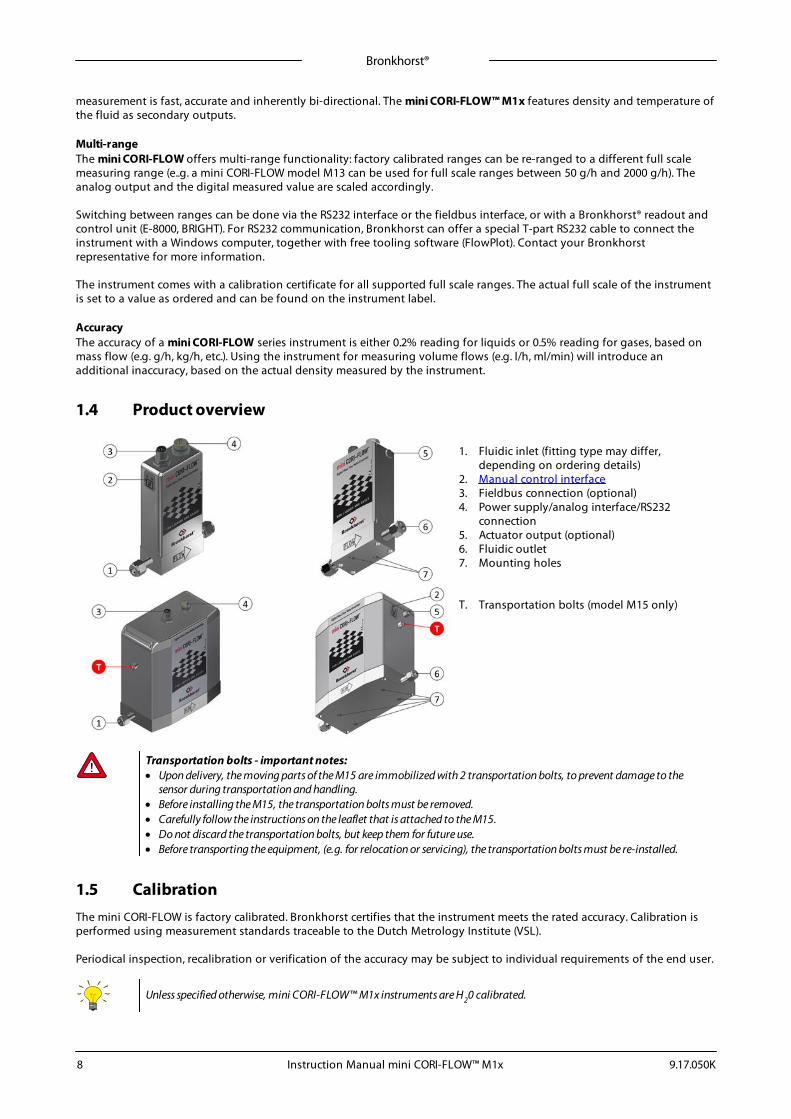
1.4 Product overview
1. Fluidic inlet (fitting type may differ,depending on ordering details)
2. Manual control interface3. Fieldbus connection (optional)4. Power supply/analog interface/RS232
connection5. Actuator output (optional)6. Fluidic outlet7. Mounting holes
T. Transportation bolts (model M15 only)
Transportation bolts - important notes:· Upon delivery, the moving parts of the M15 are immobilized with 2 transportation bolts, to prevent damage to the
sensor during transportation and handling.· Before installing the M15, the transportation bolts must be removed.· Carefully follow the instructions on the leaflet that is attached to the M15.· Do not discard the transportation bolts, but keep them for future use.· Before transporting the equipment, (e.g. for relocation or servicing), the transportation bolts must be re-installed.
1.5 CalibrationThe mini CORI-FLOW is factory calibrated. Bronkhorst certifies that the instrument meets the rated accuracy. Calibration isperformed using measurement standards traceable to the Dutch Metrology Institute (VSL).
Periodical inspection, recalibration or verification of the accuracy may be subject to individual requirements of the end user.
Unless specified otherwise, mini CORI-FLOW™ M1x instruments are H20 calibrated.
Bronkhorst®
Instruction Manual mini CORI-FLOW™ M1x9.17.050K 9
1.6 MaintenanceNo regular maintenance is required if the mini CORI-FLOW is operated properly, with clean media, compatible with thewetted materials, avoiding pressure and thermal shocks and vibrations. Units may be purged with a clean, dry and inert gasor a non-aggressive and non-corrosive solvent.
In case of severe contamination, cleaning of the inside of the instrument and of the valve orifice (if applicable) may berequired.
Inexpertly servicing instruments can lead to serious personal injury and/or damage to the instrument or the system it isused in. Therefore, servicing must be performed by trained and qualified personnel. Contact Bronkhorst for informationabout cleaning and calibration. Bronkhorst has a trained staff available.
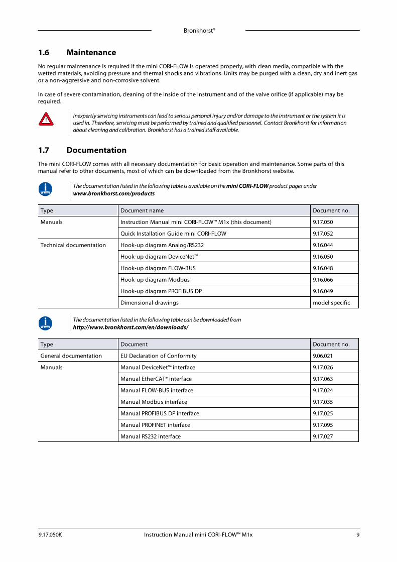
1.7 DocumentationThe mini CORI-FLOW comes with all necessary documentation for basic operation and maintenance. Some parts of thismanual refer to other documents, most of which can be downloaded from the Bronkhorst website.
The documentation listed in the following table is available on the mini CORI-FLOW product pages underwww.bronkhorst.com/products
Type Document name Document no.
Manuals Instruction Manual mini CORI-FLOW™ M1x (this document) 9.17.050
Quick Installation Guide mini CORI-FLOW 9.17.052
Technical documentation Hook-up diagram Analog/RS232 9.16.044
Hook-up diagram DeviceNet™ 9.16.050
Hook-up diagram FLOW-BUS 9.16.048
Hook-up diagram Modbus 9.16.066
Hook-up diagram PROFIBUS DP 9.16.049
Dimensional drawings model specific
The documentation listed in the following table can be downloaded from http://www.bronkhorst.com/en/downloads/
Type Document Document no.
General documentation EU Declaration of Conformity 9.06.021
Manuals Manual DeviceNet™ interface 9.17.026
Manual EtherCAT® interface 9.17.063
Manual FLOW-BUS interface 9.17.024
Manual Modbus interface 9.17.035
Manual PROFIBUS DP interface 9.17.025
Manual PROFINET interface 9.17.095
Manual RS232 interface 9.17.027
Bronkhorst®
Instruction Manual mini CORI-FLOW™ M1x 9.17.050K10
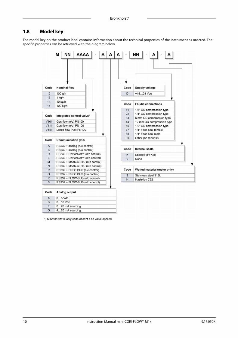
1.8 Model keyThe model key on the product label contains information about the technical properties of the instrument as ordered. Thespecific properties can be retrieved with the diagram below.
Bronkhorst®
Instruction Manual mini CORI-FLOW™ M1x9.17.050K 11
2 Installation
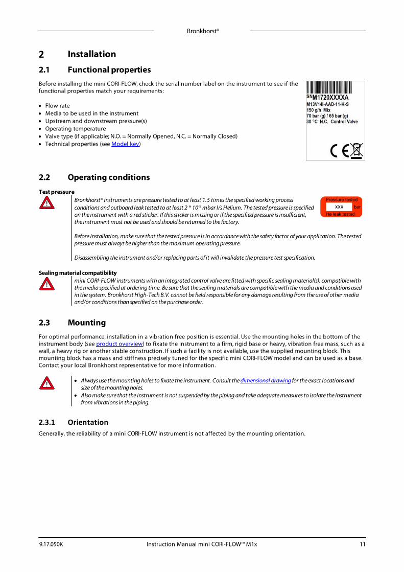
2.1 Functional propertiesBefore installing the mini CORI-FLOW, check the serial number label on the instrument to see if thefunctional properties match your requirements:
· Flow rate· Media to be used in the instrument· Upstream and downstream pressure(s)· Operating temperature· Valve type (if applicable; N.O. = Normally Opened, N.C. = Normally Closed)· Technical properties (see Model key)
2.2 Operating conditions
Test pressureBronkhorst® instruments are pressure tested to at least 1.5 times the specified working processconditions and outboard leak tested to at least 2 * 10-9 mbar l/s Helium. The tested pressure is specifiedon the instrument with a red sticker. If this sticker is missing or if the specified pressure is insufficient,the instrument must not be used and should be returned to the factory.
Before installation, make sure that the tested pressure is in accordance with the safety factor of your application. The testedpressure must always be higher than the maximum operating pressure.
Disassembling the instrument and/or replacing parts of it will invalidate the pressure test specification.
Sealing material compatibilitymini CORI-FLOW instruments with an integrated control valve are fitted with specific sealing material(s), compatible withthe media specified at ordering time. Be sure that the sealing materials are compatible with the media and conditions usedin the system. Bronkhorst High-Tech B.V. cannot be held responsible for any damage resulting from the use of other mediaand/or conditions than specified on the purchase order.
2.3 MountingFor optimal performance, installation in a vibration free position is essential. Use the mounting holes in the bottom of theinstrument body (see product overview) to fixate the instrument to a firm, rigid base or heavy, vibration free mass, such as awall, a heavy rig or another stable construction. If such a facility is not available, use the supplied mounting block. Thismounting block has a mass and stiffness precisely tuned for the specific mini CORI-FLOW model and can be used as a base. Contact your local Bronkhorst representative for more information.
· Always use the mounting holes to fixate the instrument. Consult the dimensional drawing for the exact locations andsize of the mounting holes.
· Also make sure that the instrument is not suspended by the piping and take adequate measures to isolate the instrumentfrom vibrations in the piping.
2.3.1 OrientationGenerally, the reliability of a mini CORI-FLOW instrument is not affected by the mounting orientation.
Bronkhorst®
Instruction Manual mini CORI-FLOW™ M1x 9.17.050K12
2.3.2 LocationFor gas applications, mount the instrument in a location where condensate (if any) cannot accumulate inside theinstrument's media conduits.
In liquid applications, the presence of gas bubbles in the liquid can causemeasuring errors. In general, the instrument should be mounted in a pipesegment where gas bubbles (if any) cannot accumulate. The image to theright shows the preferable mounting locations.
· The best location is a horizontal pipe segment or a segment where the fluid direction is upward.
· Gas might accumulate in a horizontal segment if it is followed by a downward segment. Do NOT mount theinstrument in a location like this.
· Mounting in a downward pipe segment with an open end is strongly dissuaded, especially if the pipediameter is 1/2" or more. Gravity might let the segment run empty; depending on the specific systemdimensions and the viscosity of the metered fluid, this effect might be stronger or weaker.
· If the instrument is part of a closed fluidic system, mounting the instrument in a downward pipe segment isnot preferable, but may be considered if other mounting locations are more problematic.
To minimize the risk of gas entrapment by cavitation, the preferred location to install a control valve is downstream fromthe instrument, for a pump the preferred location is upstream.
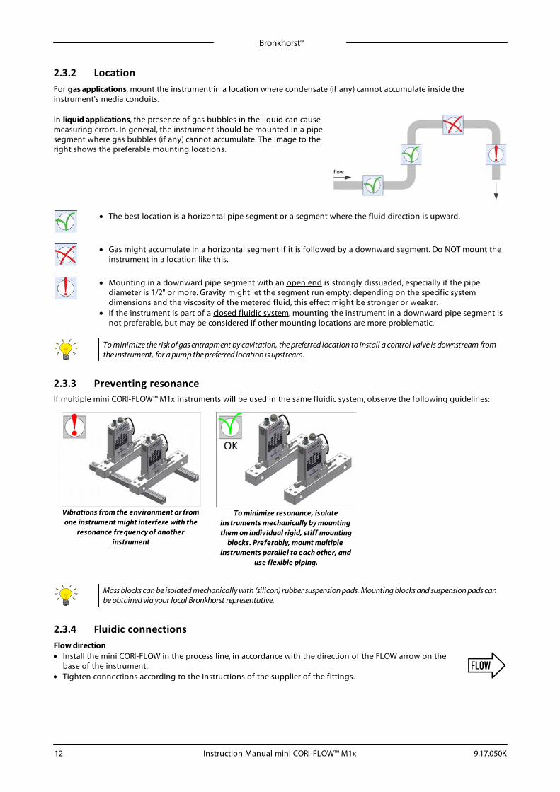
2.3.3 Preventing resonanceIf multiple mini CORI-FLOW™ M1x instruments will be used in the same fluidic system, observe the following guidelines:
Vibrations from the environment or fromone instrument might interfere with the
resonance frequency of anotherinstrument
To minimize resonance, isolateinstruments mechanically by mountingthem on individual rigid, stiff mounting
blocks. Preferably, mount multipleinstruments parallel to each other, and
use flexible piping.
Mass blocks can be isolated mechanically with (silicon) rubber suspension pads. Mounting blocks and suspension pads canbe obtained via your local Bronkhorst representative.
2.3.4 Fluidic connectionsFlow direction· Install the mini CORI-FLOW in the process line, in accordance with the direction of the FLOW arrow on the
base of the instrument.· Tighten connections according to the instructions of the supplier of the fittings.
Bronkhorst®
Instruction Manual mini CORI-FLOW™ M1x9.17.050K 13
FittingsTypically, Bronkhorst® mini CORI-FLOW meters/controllers are fitted with compression or face-seal-fittings.For leak tight installation of compression type fittings, make sure that the tube is inserted to the shoulder in the fittingbody and tube, ferrules and fittings are free of dirt or other particles. Tighten the nut finger-tight while holding theinstrument, then tighten the nut 1 turn.
If applicable follow the guidelines of the supplier of the fittings. Special fitting types are available on request.
Check the fluidic system for leaks before applying pressure, especially if toxic, explosive or other dangerous fluids are used.
After using the mini CORI-FLOW for the first time with low temperature media, re-tighten the fluidic connections, in orderto prevent leakage.
2.3.5 Piping requirementsDuring the manufacturing process, the instrument has been tested with water. Despite the fact that it has been purgedthoroughly afterward, the instrument cannot be guaranteed to be absolutely free of water droplets upon delivery. Forapplications where remaining water particles might cause undesired reactions, such as corrosion, Bronkhorst stronglyrecommends performing an additional, adequate drying procedure, as described in Liquid application and Gasapplication.
· Do not install small diameter piping on high flow rates and avoid abrupt angles or other disturbances within a distanceof 10 pipe diameters from the inlet or outlet of the device.
· Do not install pressure regulators within a distance of 25 pipe diameters.
2.4 Preventing pressure shocks
mini CORI-FLOW instruments handle pressure shocks in the system well, but are not insensitive to pressure fluctuations. Foroptimal control stability, observe the following guidelines:
· Provide a stable (pressure controlled) inlet pressure; put sufficient buffer volume between the pressure regulator and theinstrument. As a rule of thumb, install pressure regulators at a distance of at least 25 times the pipe diameter from theinlet or outlet of the instrument.
· When using multiple instruments and/or control valves, prevent interference by putting piping with sufficient buffervolume between components
· Avoid installing multiple instruments or control valves in close proximity to another
2.5 Preventing hydraulic shocks
In a fluidic system where fluid movement (liquid or gas) is forced to stop or start suddenly (by a pump or a shut-off valve), ahydraulic shocks(or fluid hammer) can occur, especially if the fluid velocity is high. This momentum change causes apressure surge (spike) traveling repeatedly from one end of the piping to the other. Rapid pressure fluctuations like this cancause leakage and damage to fluidic lines and components, and ultimately damage to the instrument.
The following measures can be taken to prevent or minimize hydraulic shocks:
· Avoid abrupt fluid acceleration and decelerationo Avoid large pipe diameter transitions by using piping and tubing with an inside diameter that matches that of the
instrument as closely as possibleo Keep the fluid velocity through the instrument as small as possible
· Install an accumulator to dampen acceleration and deceleration of the fluid flow
Consult your Bronkhorst representative if you need more information about prevention of hydraulic shocks.
Bronkhorst®
Instruction Manual mini CORI-FLOW™ M1x 9.17.050K14
2.6 Electrical connectionElectrical connections must be made with standard cables or according to the applicable hook-up diagrams. Make sure thatthe power supply is suitable for the power ratings as indicated on the serial number label (see model key), and that doubleor reinforced insulation is used for the power supply cabling. For use in fieldbus systems, follow the instructions of thecable supplier for the specific fieldbus system.
The device contains electronic components that are susceptible to damage by electrostatic discharge. Proper handlingprocedures must be followed during installation, (dis)connecting and removing the electronics.
The device described in this manual carries the CE-mark and is compliant with the concerning EMC requirements.However, compliance with the EMC requirements is not possible without the use of proper cables and connector/glandassemblies. Bronkhorst recommends the use of their standard cables. These cables have the right connectors and if looseends are used, these are marked to help prevent wrong connection. When using other cables, cable wire diameters shouldbe sufficient to carry the supply current, and voltage loss must be kept as low as possible. When in doubt, contact yourdistributor.
When connecting the product to other devices, be sure that the integrity of the shielding is not affected; always useshielded cabling for signals and communication and do not use unshielded wire terminals.
Never power the instrument simultaneously from two different power sources (e.g. fieldbus connection and Plug-inPower Supply). Doing so will damage the printed circuit board irreparably.
Always power down the system before connecting or disconnecting instruments.
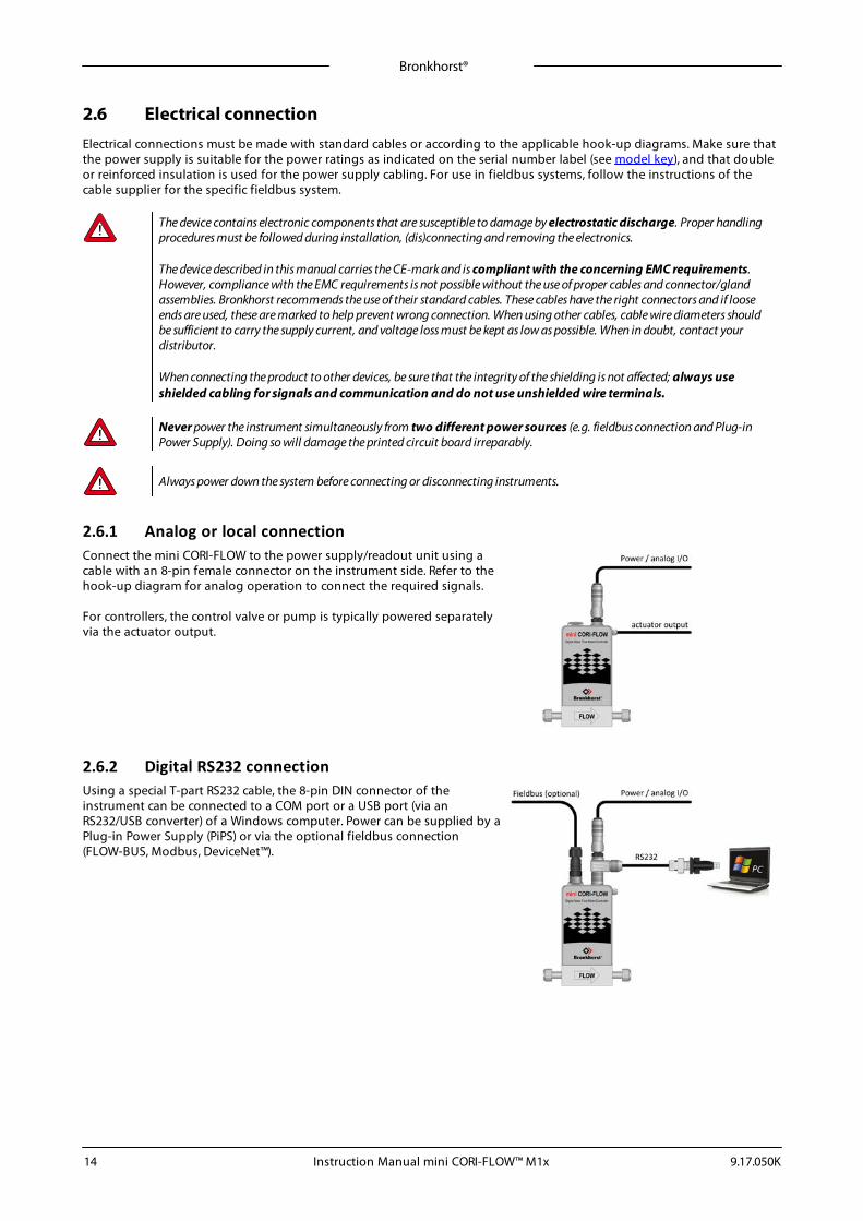
2.6.1 Analog or local connectionConnect the mini CORI-FLOW to the power supply/readout unit using acable with an 8-pin female connector on the instrument side. Refer to thehook-up diagram for analog operation to connect the required signals.
For controllers, the control valve or pump is typically powered separatelyvia the actuator output.
2.6.2 Digital RS232 connectionUsing a special T-part RS232 cable, the 8-pin DIN connector of theinstrument can be connected to a COM port or a USB port (via anRS232/USB converter) of a Windows computer. Power can be supplied by aPlug-in Power Supply (PiPS) or via the optional fieldbus connection(FLOW-BUS, Modbus, DeviceNet™).
Bronkhorst®
Instruction Manual mini CORI-FLOW™ M1x9.17.050K 15
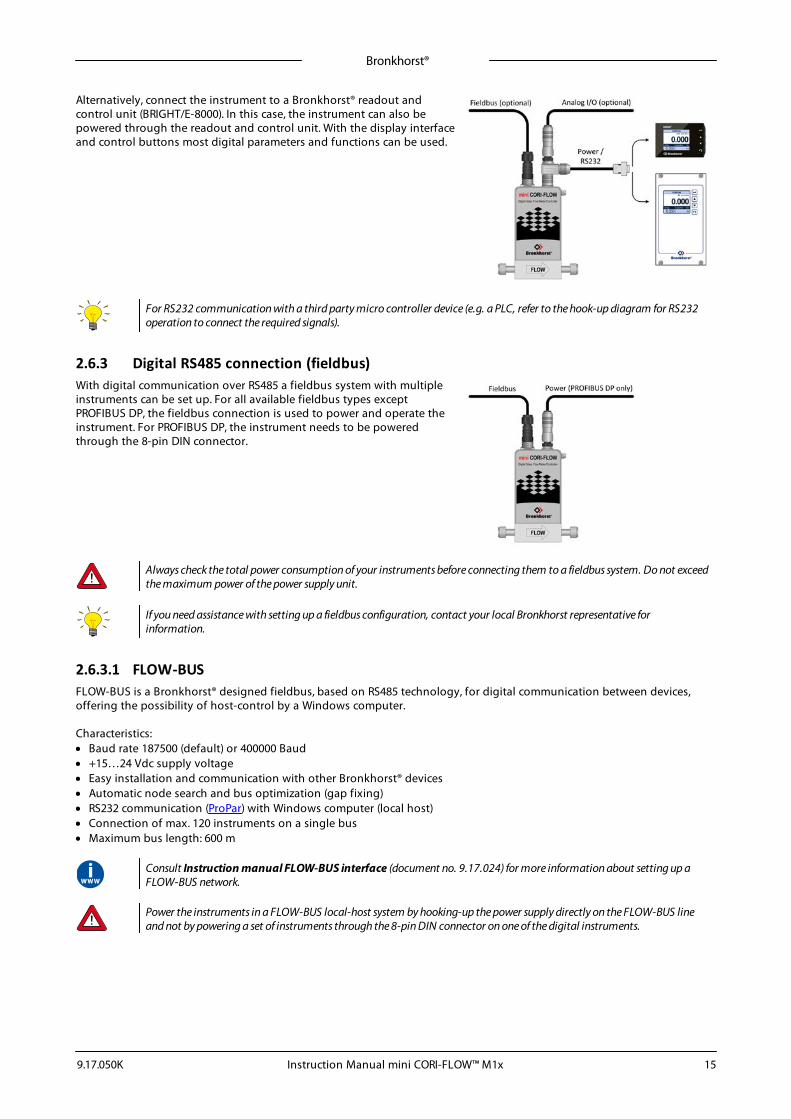
Alternatively, connect the instrument to a Bronkhorst® readout andcontrol unit (BRIGHT/E-8000). In this case, the instrument can also bepowered through the readout and control unit. With the display interfaceand control buttons most digital parameters and functions can be used.
For RS232 communication with a third party micro controller device (e.g. a PLC, refer to the hook-up diagram for RS232operation to connect the required signals).
2.6.3 Digital RS485 connection (fieldbus)With digital communication over RS485 a fieldbus system with multipleinstruments can be set up. For all available fieldbus types exceptPROFIBUS DP, the fieldbus connection is used to power and operate theinstrument. For PROFIBUS DP, the instrument needs to be poweredthrough the 8-pin DIN connector.
Always check the total power consumption of your instruments before connecting them to a fieldbus system. Do not exceedthe maximum power of the power supply unit.
If you need assistance with setting up a fieldbus configuration, contact your local Bronkhorst representative forinformation.
2.6.3.1 FLOW-BUSFLOW-BUS is a Bronkhorst® designed fieldbus, based on RS485 technology, for digital communication between devices,offering the possibility of host-control by a Windows computer.
Characteristics:· Baud rate 187500 (default) or 400000 Baud· +15…24 Vdc supply voltage· Easy installation and communication with other Bronkhorst® devices· Automatic node search and bus optimization (gap fixing)· RS232 communication (ProPar) with Windows computer (local host)· Connection of max. 120 instruments on a single bus· Maximum bus length: 600 m
Consult Instruction manual FLOW-BUS interface (document no. 9.17.024) for more information about setting up aFLOW-BUS network.
Power the instruments in a FLOW-BUS local-host system by hooking-up the power supply directly on the FLOW-BUS lineand not by powering a set of instruments through the 8-pin DIN connector on one of the digital instruments.
Bronkhorst®
Instruction Manual mini CORI-FLOW™ M1x 9.17.050K16
2.6.3.2 ModbusModbus is a 3-wire, RS485-based fieldbus communication system for parameter value exchange. In this system eachinstrument/device is equipped with a micro-controller for its own dedicated task. The instrument behaves as a slave, whichmeans all communication (instructions and readout) is initiated by a master device on the Modbus system.
Characteristics:· Baud rate selectable between 9600 and 256000 Baud (default: 19200 Baud)· +15…24 Vdc supply voltage· Connection of max. 247 instruments on a single bus· Supports RTU and ASCII protocols
Consult Instruction manual Modbus interface (document no. 9.17.035) for more information about setting up aModbus network.
Detailed information about Modbus can be found at http://www.modbus.org/ or any website of the (local) Modbusorganization of your country (if available).
2.6.3.3 PROFIBUS DPPROFIBUS DP is a 2-wire, RS485-based industrial data communication standard (fieldbus) which allows automationcomponents (e.g. sensors, actuators and controllers) to exchange information.
Consult Instruction manual PROFIBUS DP interface (document no. 9.17.025) for more information about setting up aPROFIBUS DP network.
2.6.3.4 DeviceNet™The DeviceNet™ interface offers a direct connection to a DeviceNet™ network, according to the mass flow controller profilespecified by the ODVA. The Bronkhorst® DeviceNet™ instrument is a Group 2 Only Server device whose messages complywith the Controlled Area Network (CAN) 2.0A standard and with the DeviceNet™ protocol.
Consult Instruction manual DeviceNet™ interface (document no. 9.17.026) for more information about setting up aDeviceNet™ network.
Bronkhorst®
Instruction Manual mini CORI-FLOW™ M1x9.17.050K 17
3 OperationAfter correct installation of the mini CORI-FLOW™ M1x Mass Flow Meter (MFM) or Mass Flow Controller (MFC), and when allsafety precautions have been taken into account, the instrument can be used for measuring/ controlling the required flowrate in the system.
3.1 Powering up and powering down
· It is recommended to turn on power before applying pressure and to switch off power after removing pressure.· For best performance, allow the device to warm up and stabilize for at least 30 minutes before starting measurement
and/or control. This may be done with or without media flow.
Be sure to apply the specified operating pressure(s). Avoid pressure shocks and bring the fluidic system gradually up to thelevel of operating conditions; open and close the fluid supply gently.
3.2 First use
Adequate mass flow measurement is only possible if the fluid flows through the instrument in a single state (either gas orliquid). To prevent 'slug flow' (two-phase flow) at start-up, take the following measures before starting measurement andcontrol:· for liquid applications, expel gas from the system, by flushing the instrument and all fluidic lines with the process fluid at
a relatively high flow rate· for gas applications, expel condensation from the system, by purging the instrument and all fluidic lines with a dry gas
at a relatively high flow rate
In systems for use with corrosive, reactive or explosive media, purging the fluidic lines of the device for at least 30 minuteswith a dry, inert gas (like Nitrogen or Argon) is absolutely necessary before use. After use with these media, completepurging is also required before exposing the system to air.
The very first time the instrument is used, adjusting the zero point is recommended. See Adjusting zero point forbackground information and instructions.
3.3 Valve Safe StateWhen a controlling instrument is not powered, the control valve automatically returns to its 'Safe State', which is closed fora 'normally closed' valve (n/c) and fully open for a 'normally opened' valve (n/o). To protect the system, certain events (suchas communication errors) may cause the instrument to switch to Valve Safe State (see also LED indications).
Check the serial number label or the technical specifications to see which valve type is used on your instrument (ifapplicable).
3.4 Mass flow measurement and controlWhen powering up, the instrument needs a couple of seconds to start up the electronics. A soon as the start-up sequence isfinished (green LED glows continuously), the instrument is ready to measure mass flows, however, optimal accuracy is onlyreached after warming up (see Powering up and powering down).
After powering up, the control valve closes (normally opened) or stays closed (normally closed). The valve stays closed untilthe instrument receives a setpoint from the active setpoint source. The internal PID controller then immediately opens thecontrol valve, until the measured flow rate matches the setpoint. It maintains the resulting flow rate until another setpointis given.
Bronkhorst®
Instruction Manual mini CORI-FLOW™ M1x 9.17.050K18
3.5 Temperature considerationsAlthough the mini CORI-FLOW has excellent temperature stability, the best accuracy is achieved when temperaturegradients within and across the instrument are avoided. Take the following guidelines into account:
· To avoid simultaneous heating and cooling of different parts of the instrument, make sure the ambient temperature isas stable and evenly distributed across the environment as possible.
· Avoid temperature shocks; heating or cooling should amount to no more than 1 °C per second.· Make sure that the media temperature matches the ambient temperature as closely as possible.· The mini CORI-FLOW will show an amount of self heating, due to power dissipation of the electronics. This effect can be
as large as approximately 15 °C (depending on media and ambient temperature). In practice, there will be a balancebetween media temperature, self heating and ambient temperature.
· Operation in a cool environment can compensate somewhat for the effect of high media temperatures.· Heating and cooling effects will also depend on the cooling/heat conducting capacities of the installation itself on which
the instrument is mounted.
· To prevent damage to the electronics, make sure the temperature in the housing never exceeds 70°C. To monitor this,the internal temperature reading can be used (parameter Temperature).
· The storage temperature should lie between -30 and 80 °C. Make sure the measuring tube is purged and dry beforestoring the instrument.
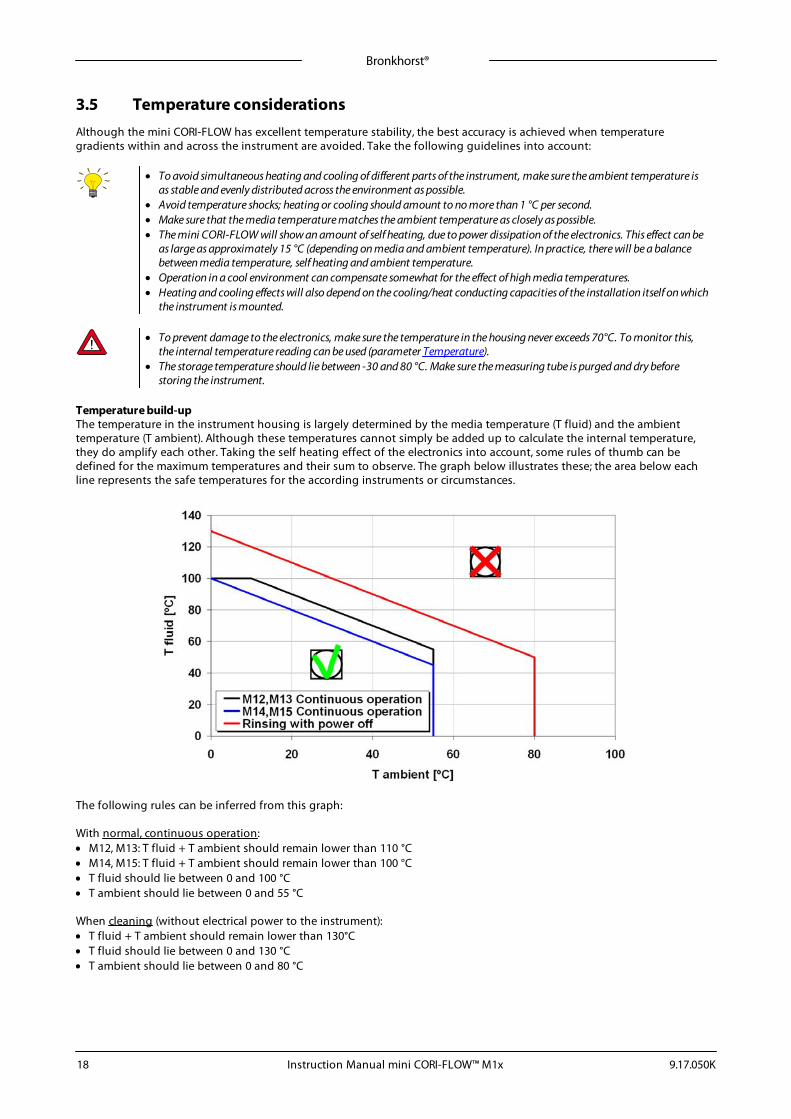
Temperature build-upThe temperature in the instrument housing is largely determined by the media temperature (T fluid) and the ambienttemperature (T ambient). Although these temperatures cannot simply be added up to calculate the internal temperature,they do amplify each other. Taking the self heating effect of the electronics into account, some rules of thumb can bedefined for the maximum temperatures and their sum to observe. The graph below illustrates these; the area below eachline represents the safe temperatures for the according instruments or circumstances.
The following rules can be inferred from this graph:
With normal, continuous operation:· M12, M13: T fluid + T ambient should remain lower than 110 °C· M14, M15: T fluid + T ambient should remain lower than 100 °C· T fluid should lie between 0 and 100 °C· T ambient should lie between 0 and 55 °C
When cleaning (without electrical power to the instrument):· T fluid + T ambient should remain lower than 130°C· T fluid should lie between 0 and 130 °C· T ambient should lie between 0 and 80 °C
Bronkhorst®
Instruction Manual mini CORI-FLOW™ M1x9.17.050K 19
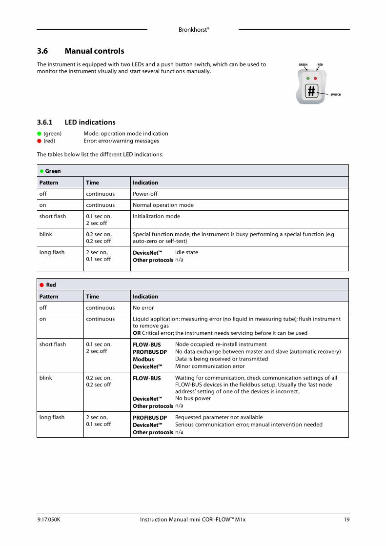
3.6 Manual controlsThe instrument is equipped with two LEDs and a push button switch, which can be used tomonitor the instrument visually and start several functions manually.
3.6.1 LED indications
• (green) Mode: operation mode indication
• (red) Error: error/warning messages
The tables below list the different LED indications:
• Green
Pattern Time Indication
off continuous Power-off
on continuous Normal operation mode
short flash 0.1 sec on, 2 sec off
Initialization mode
blink 0.2 sec on, 0.2 sec off
Special function mode; the instrument is busy performing a special function (e.g.auto-zero or self-test)
long flash 2 sec on,0.1 sec off
DeviceNet™ Idle stateOther protocols n/a
• Red
Pattern Time Indication
off continuous No error
on continuous Liquid application: measuring error (no liquid in measuring tube); flush instrumentto remove gasOR Critical error; the instrument needs servicing before it can be used
short flash 0.1 sec on,2 sec off
FLOW-BUS Node occupied: re-install instrumentPROFIBUS DP No data exchange between master and slave (automatic recovery)Modbus Data is being received or transmittedDeviceNet™ Minor communication error
blink 0.2 sec on,0.2 sec off
FLOW-BUS Waiting for communication, check communication settings of allFLOW-BUS devices in the fieldbus setup. Usually the ‘last nodeaddress’ setting of one of the devices is incorrect.
DeviceNet™ No bus powerOther protocols n/a
long flash 2 sec on,0.1 sec off
PROFIBUS DP Requested parameter not availableDeviceNet™ Serious communication error; manual intervention neededOther protocols n/a
Bronkhorst®
Instruction Manual mini CORI-FLOW™ M1x 9.17.050K20
• Green and • red (alternating)
Pattern Time Indication
slow wink 1 sec on,1 sec off
Alarm indication; minimum/maximum alarm, power-up alarm, limit reached or batchsize reached
normal wink 0.2 sec on,0.2 sec off
Wink mode; by sending a command to the Wink parameter, the instrument flashes itsLEDs to indicate its physical location
fast wink 0.1 sec on,0.1 sec off
Selected action started (after releasing the multifunctional switch)
3.6.2 Multifunctional switchSome special functions of the instrument can be started manually using the multifunctional switch near the indicationLEDs. These functions are available in analog as well as in digital operation mode.
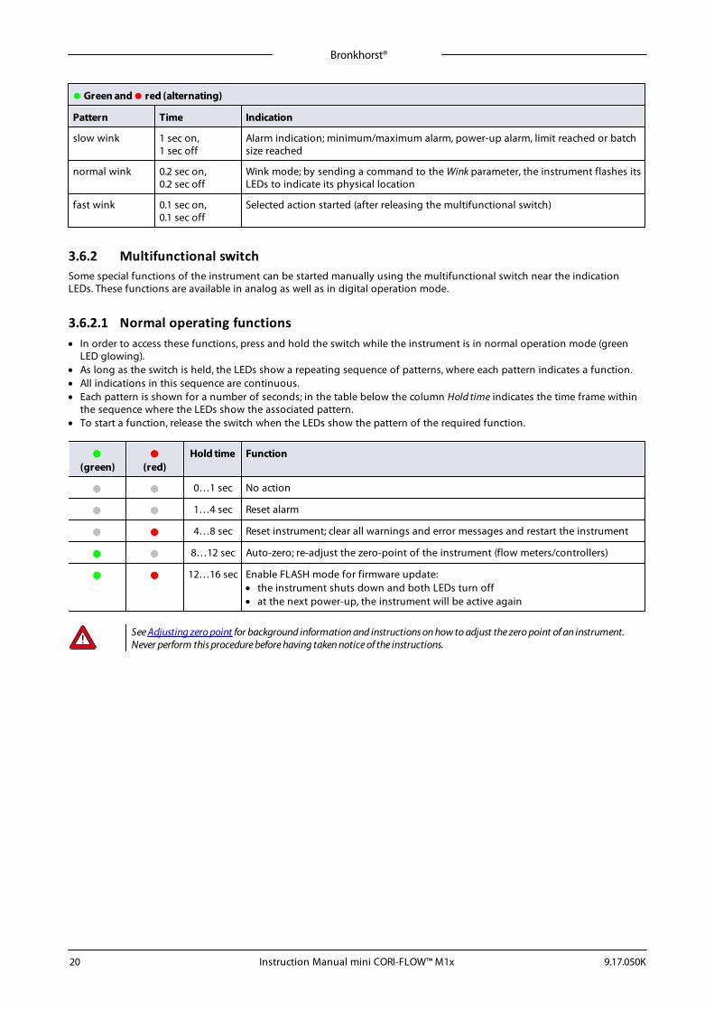
3.6.2.1 Normal operating functions· In order to access these functions, press and hold the switch while the instrument is in normal operation mode (green
LED glowing).· As long as the switch is held, the LEDs show a repeating sequence of patterns, where each pattern indicates a function.· All indications in this sequence are continuous.· Each pattern is shown for a number of seconds; in the table below the column Hold time indicates the time frame within
the sequence where the LEDs show the associated pattern.· To start a function, release the switch when the LEDs show the pattern of the required function.
•(green)
•(red)
Hold time Function
• • 0…1 sec No action
• • 1…4 sec Reset alarm
• • 4…8 sec Reset instrument; clear all warnings and error messages and restart the instrument
• • 8…12 sec Auto-zero; re-adjust the zero-point of the instrument (flow meters/controllers)
• • 12…16 sec Enable FLASH mode for firmware update:· the instrument shuts down and both LEDs turn off· at the next power-up, the instrument will be active again
See Adjusting zero point for background information and instructions on how to adjust the zero point of an instrument.Never perform this procedure before having taken notice of the instructions.
Bronkhorst®
Instruction Manual mini CORI-FLOW™ M1x9.17.050K 21
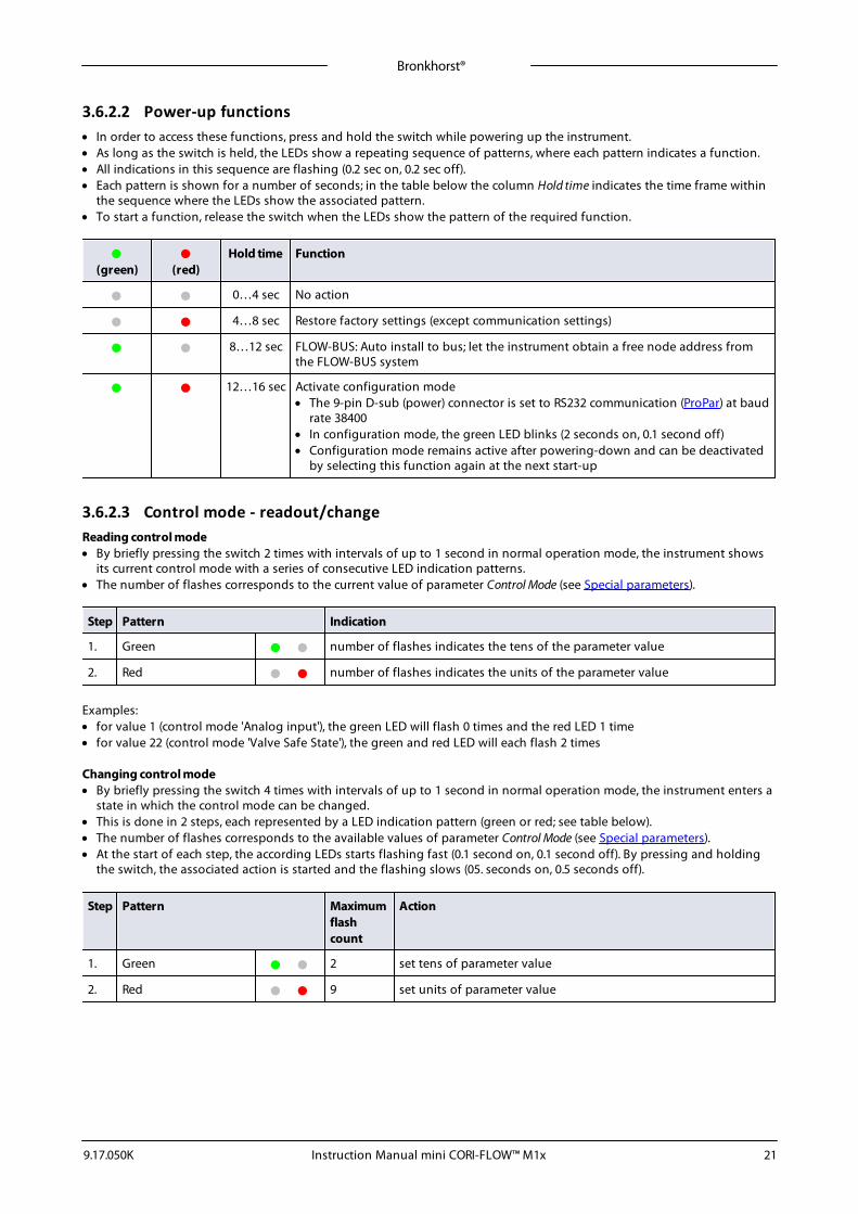
3.6.2.2 Power-up functions· In order to access these functions, press and hold the switch while powering up the instrument.· As long as the switch is held, the LEDs show a repeating sequence of patterns, where each pattern indicates a function.· All indications in this sequence are flashing (0.2 sec on, 0.2 sec off).· Each pattern is shown for a number of seconds; in the table below the column Hold time indicates the time frame within
the sequence where the LEDs show the associated pattern.· To start a function, release the switch when the LEDs show the pattern of the required function.
•(green)
•(red)
Hold time Function
• • 0…4 sec No action
• • 4…8 sec Restore factory settings (except communication settings)
• • 8…12 sec FLOW-BUS: Auto install to bus; let the instrument obtain a free node address fromthe FLOW-BUS system
• • 12…16 sec Activate configuration mode· The 9-pin D-sub (power) connector is set to RS232 communication (ProPar) at baud
rate 38400· In configuration mode, the green LED blinks (2 seconds on, 0.1 second off)· Configuration mode remains active after powering-down and can be deactivated
by selecting this function again at the next start-up
3.6.2.3 Control mode - readout/changeReading control mode· By briefly pressing the switch 2 times with intervals of up to 1 second in normal operation mode, the instrument shows
its current control mode with a series of consecutive LED indication patterns.· The number of flashes corresponds to the current value of parameter Control Mode (see Special parameters).
Step Pattern Indication
1. Green • • number of flashes indicates the tens of the parameter value
2. Red • • number of flashes indicates the units of the parameter value
Examples:· for value 1 (control mode 'Analog input'), the green LED will flash 0 times and the red LED 1 time· for value 22 (control mode 'Valve Safe State'), the green and red LED will each flash 2 times
Changing control mode· By briefly pressing the switch 4 times with intervals of up to 1 second in normal operation mode, the instrument enters a
state in which the control mode can be changed.· This is done in 2 steps, each represented by a LED indication pattern (green or red; see table below).· The number of flashes corresponds to the available values of parameter Control Mode (see Special parameters).· At the start of each step, the according LEDs starts flashing fast (0.1 second on, 0.1 second off). By pressing and holding
the switch, the associated action is started and the flashing slows (05. seconds on, 0.5 seconds off).
Step Pattern Maximumflashcount
Action
1. Green • • 2 set tens of parameter value
2. Red • • 9 set units of parameter value
Bronkhorst®
Instruction Manual mini CORI-FLOW™ M1x 9.17.050K22
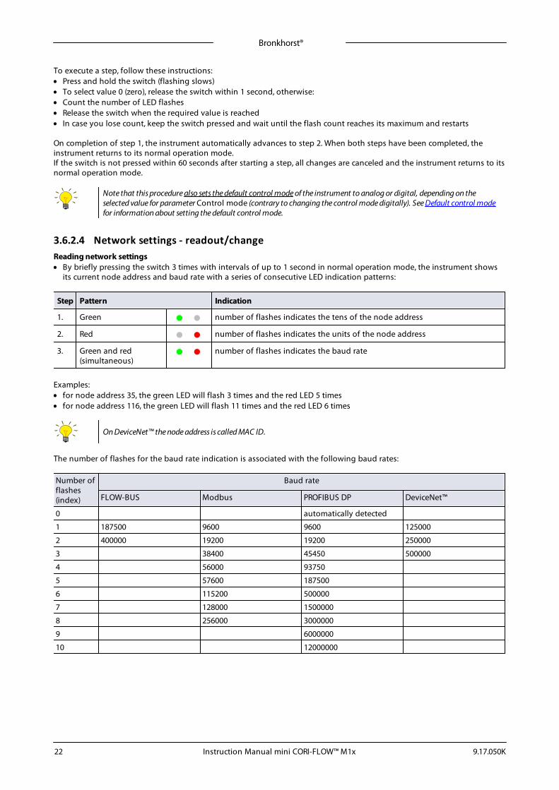
To execute a step, follow these instructions:· Press and hold the switch (flashing slows)· To select value 0 (zero), release the switch within 1 second, otherwise:· Count the number of LED flashes· Release the switch when the required value is reached· In case you lose count, keep the switch pressed and wait until the flash count reaches its maximum and restarts
On completion of step 1, the instrument automatically advances to step 2. When both steps have been completed, theinstrument returns to its normal operation mode.If the switch is not pressed within 60 seconds after starting a step, all changes are canceled and the instrument returns to itsnormal operation mode.
Note that this procedure also sets the default control mode of the instrument to analog or digital, depending on theselected value for parameter Control mode (contrary to changing the control mode digitally). See Default control modefor information about setting the default control mode.
3.6.2.4 Network settings - readout/changeReading network settings· By briefly pressing the switch 3 times with intervals of up to 1 second in normal operation mode, the instrument shows
its current node address and baud rate with a series of consecutive LED indication patterns:
Step Pattern Indication
1. Green • • number of flashes indicates the tens of the node address
2. Red • • number of flashes indicates the units of the node address
3. Green and red(simultaneous)
• • number of flashes indicates the baud rate
Examples:· for node address 35, the green LED will flash 3 times and the red LED 5 times· for node address 116, the green LED will flash 11 times and the red LED 6 times
On DeviceNet™ the node address is called MAC ID.
The number of flashes for the baud rate indication is associated with the following baud rates:
Number offlashes(index)
Baud rate
FLOW-BUS Modbus PROFIBUS DP DeviceNet™
0 automatically detected
1 187500 9600 9600 125000
2 400000 19200 19200 250000
3 38400 45450 500000
4 56000 93750
5 57600 187500
6 115200 500000
7 128000 1500000
8 256000 3000000
9 6000000
10 12000000
Bronkhorst®
Instruction Manual mini CORI-FLOW™ M1x9.17.050K 23
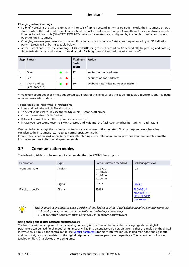
Changing network settings· By briefly pressing the switch 5 times with intervals of up to 1 second in normal operation mode, the instrument enters a
state in which the node address and baud rate of the instrument can be changed (non-Ethernet based protocols only; forEthernet based protocols (EtherCAT®, PROFINET), network parameters are configured by the fieldbus master and cannotbe set on the instrument).
· Changing network parameters with the multifunctional switch is done in 3 steps, each represented by a LED indicationpattern (green, red or both; see table below).
· At the start of each step, the according LED(s) start(s) flashing fast (0.1 second on, 0.1 second off). By pressing and holdingthe switch, the associated action is started and the flashing slows (05. seconds on, 0.5 seconds off).
Step Pattern Maximumflashcount
Action
1. Green • • 12 set tens of node address
2. Red • • 9 set units of node address
3. Green and red(simultaneous)
• • 10* set baud rate index (number of flashes)
*) maximum count depends on the supported baud rates of the fieldbus. See the baud rate table above for supported baudrates and associated indexes.
To execute a step, follow these instructions:· Press and hold the switch (flashing slows)· To select value 0 (zero), release the switch within 1 second, otherwise:· Count the number of LED flashes· Release the switch when the required value is reached· In case you lose count, keep the switch pressed and wait until the flash count reaches its maximum and restarts
On completion of a step, the instrument automatically advances to the next step. When all required steps have beencompleted, the instrument returns to its normal operation mode.If the switch is not pressed within 60 seconds after starting a step, all changes in the previous steps are canceled and theinstrument returns to its normal operation mode.
3.7 Communication modesThe following table lists the communication modes the mini CORI-FLOW supports:
Connection Type Communication standard Fieldbus/protocol
8-pin DIN male Analog 0…5Vdc0…10Vdc0…20mA4…20mA
n/a
Digital RS232 ProPar
Fieldbus specific Digital RS485 FLOW-BUSModbus RTUPROFIBUS DPDeviceNet™
The communication standards (analog and digital) and fieldbus interface (if applicable) are specified at ordering time, i.e.:o In analog mode, the instrument is set to the specified voltage/current rangeo The dedicated fieldbus connection only provides the specified fieldbus interface
Using analog and digital interfaces simultaneouslyThe instrument can be operated via the analog and a digital interface at the same time; analog signals and digitalparameters can be read (or changed) simultaneously. The instrument accepts a setpoint from either the analog or the digitalinterface (this is called the control mode; see Special parameters for more information). In analog mode, the analog inputand output signals are translated to the digital setpoint and measure parameter respectively. The default control mode(analog or digital) is selected at ordering time.
Bronkhorst®
Instruction Manual mini CORI-FLOW™ M1x 9.17.050K24
3.7.1 Analog operationWith analog operation the following parameters are available:
· output signal: measured value (voltage or amperage)· input signal: setpoint (voltage or amperage; controller only)· valve voltage (controller only)
Setpoints below 2% of the full scale will be interpreted as 0%.
3.7.2 Digital RS232 operationDigital operation via RS232 or fieldbus (RS485) adds extra features to the instrument, such as:
· Direct reading with a readout/control module or host computer· Diagnostics· Device identification· Adjustable minimum and maximum alarm limits (Alarms)· (Batch) counter (Counter)
Make sure in FlowDDE the correct port and baud rate are selected. For RS232 operation the baud rate must be 38400Baud.
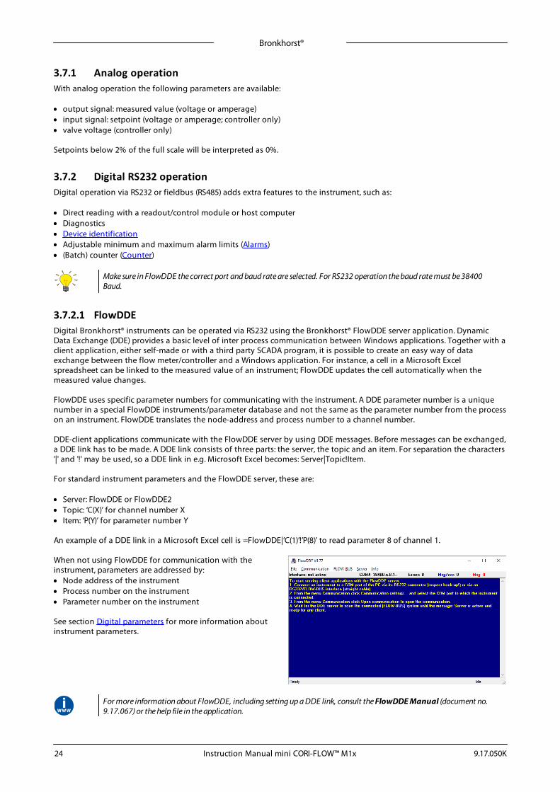
3.7.2.1 FlowDDEDigital Bronkhorst® instruments can be operated via RS232 using the Bronkhorst® FlowDDE server application. DynamicData Exchange (DDE) provides a basic level of inter process communication between Windows applications. Together with aclient application, either self-made or with a third party SCADA program, it is possible to create an easy way of dataexchange between the flow meter/controller and a Windows application. For instance, a cell in a Microsoft Excelspreadsheet can be linked to the measured value of an instrument; FlowDDE updates the cell automatically when themeasured value changes.
FlowDDE uses specific parameter numbers for communicating with the instrument. A DDE parameter number is a uniquenumber in a special FlowDDE instruments/parameter database and not the same as the parameter number from the processon an instrument. FlowDDE translates the node-address and process number to a channel number.
DDE-client applications communicate with the FlowDDE server by using DDE messages. Before messages can be exchanged,a DDE link has to be made. A DDE link consists of three parts: the server, the topic and an item. For separation the characters'|' and '!' may be used, so a DDE link in e.g. Microsoft Excel becomes: Server|Topic!Item.
For standard instrument parameters and the FlowDDE server, these are:
· Server: FlowDDE or FlowDDE2· Topic: ‘C(X)’ for channel number X· Item: ‘P(Y)’ for parameter number Y
An example of a DDE link in a Microsoft Excel cell is =FlowDDE|’C(1)’!’P(8)’ to read parameter 8 of channel 1.
When not using FlowDDE for communication with theinstrument, parameters are addressed by:· Node address of the instrument· Process number on the instrument· Parameter number on the instrument
See section Digital parameters for more information aboutinstrument parameters.
For more information about FlowDDE, including setting up a DDE link, consult the FlowDDE Manual (document no.9.17.067) or the help file in the application.
Bronkhorst®
Instruction Manual mini CORI-FLOW™ M1x9.17.050K 25
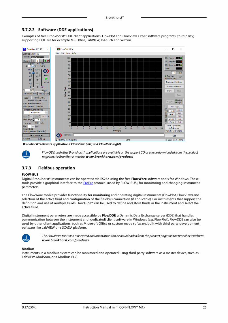
3.7.2.2 Software (DDE applications)Examples of free Bronkhorst® DDE client applications: FlowPlot and FlowView. Other software programs (third party)supporting DDE are for example MS-Office, LabVIEW, InTouch and Wizcon.
Bronkhorst® software applications 'FlowView' (left) and 'FlowPlot' (right)
FlowDDE and other Bronkhorst® applications are available on the support CD or can be downloaded from the productpages on the Bronkhorst website: www.bronkhorst.com/products
3.7.3 Fieldbus operationFLOW-BUSDigital Bronkhorst® instruments can be operated via RS232 using the free FlowWare software tools for Windows. Thesetools provide a graphical interface to the ProPar protocol (used by FLOW-BUS), for monitoring and changing instrumentparameters.
The FlowWare toolkit provides functionality for monitoring and operating digital instruments (FlowPlot, FlowView) andselection of the active fluid and configuration of the fieldbus connection (if applicable). For instruments that support thedefinition and use of multiple fluids FlowTune™ can be used to define and store fluids in the instrument and select theactive fluid.
Digital instrument parameters are made accessible by FlowDDE, a Dynamic Data Exchange server (DDE) that handlescommunication between the instrument and (dedicated) client software in Windows (e.g. FlowPlot). FlowDDE can also beused by other client applications, such as Microsoft Office or custom made software, built with third party developmentsoftware like LabVIEW or a SCADA platform.
The FlowWare tools and associated documentation can be downloaded from the product pages on the Bronkhorst website:www.bronkhorst.com/products
ModbusInstruments in a Modbus system can be monitored and operated using third party software as a master device, such asLabVIEW, ModScan, or a Modbus PLC.
Bronkhorst®
Instruction Manual mini CORI-FLOW™ M1x 9.17.050K26
PROFIBUS-DPInstruments in a PROFIBUS DP system can be monitored and operated using third party software as a master device, such asTIA Portal (by Siemens).
To configure a device, a so-called GSD file (General Station Description) can be loaded into the software. The GSD filecontains all necessary configuration information to operate the device in a PROFIBUS DP system, including communicationand network configuration, all available operating parameters, their data types, and supported data ranges.
A GSD file for Bronkhorst® instruments can be downloaded from the product pages on the Bronkhorst website: www.bronkhorst.com/products
DeviceNet™Instruments in a DeviceNet™ system can be monitored and operated using third party software as a master device, such asTIA Portal (by Siemens).
To configure a device, a so-called EDS file (Electronics Data Sheet) can be loaded into the software. The EDS file contains allnecessary configuration information to operate the device in a DeviceNet™ system, including communication and networkconfiguration, all available operating parameters, their data types, and supported data ranges.
An EDS file for Bronkhorst® instruments can be downloaded from the product pages on the Bronkhorst website: www.bronkhorst.com/products
3.8 Adjusting zero point
Zero-stabilityDue to the mechanical characteristics of its sensor tube, a (very small) offset signal is inherent to a mass flowmeter/controller. As a result of this zero-stability error, a flow may be detected when actually there is none.
The zero-stability error can be neutralized by adjusting the zero point of the instrument (the signal that corresponds to zeroflow). Immediately after zeroing, the zero-stability error is 0%. In ideal situations, i.e. when process conditions are constant,the error will remain unchanged.
A certain tolerance around the zero point is allowable. Significant changes in ambient or process conditions, however, canaffect the zero-stability error to the extent that the instrument needs to be adapted to the new conditions, by re-adjustingthe zero point.
The zero point of a Bronkhorst® flow meter/controller is factory adjusted at approximately 20 °C and atmospheric pressure,with the instrument positioned upright. If the ambient conditions or mounting orientation are significantly different,zeroing a new instrument is recommended before using it for the first time.
The following factors affect the zero-stability error (in order of importance):
· fluid temperature· ambient temperature· mounting orientation· (inlet) pressure· fluid density· fluid viscosity· vibrations from the environment· pressure fluctuations
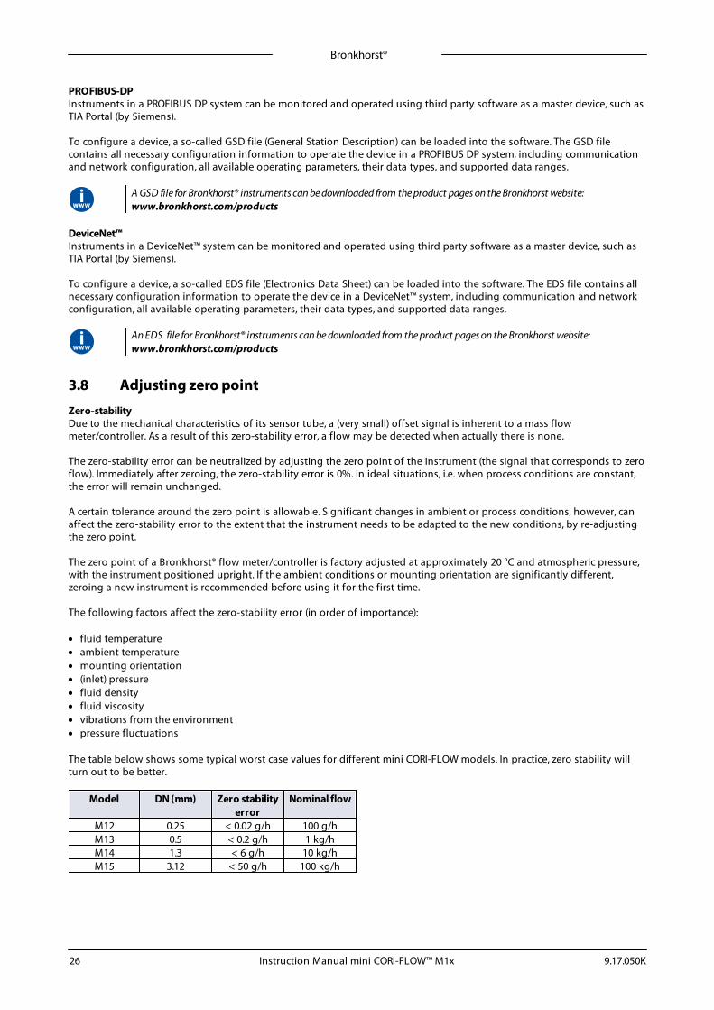
The table below shows some typical worst case values for different mini CORI-FLOW models. In practice, zero stability willturn out to be better.
Model DN (mm) Zero stabilityerror
Nominal flow
M12 0.25 < 0.02 g/h 100 g/hM13 0.5 < 0.2 g/h 1 kg/hM14 1.3 < 6 g/h 10 kg/hM15 3.12 < 50 g/h 100 kg/h
Bronkhorst®
Instruction Manual mini CORI-FLOW™ M1x9.17.050K 27
PrerequisitesZeroing an instrument requires that:
· the ambient conditions (temperature, pressure) match those of the operating environment of the instrument· the instrument is filled homogeneously with the operational media· there is absolutely no flow through the instrument; preferably, this is achieved by closing a valve immediately after the
outlet of the instrument (control valve, shut-off valve)
Blocking the flow through the instrument is absolutely essential; zeroing an instrument while there is still a flow will lead tomeasurement errors.
MethodsAdjusting the zero point of an instrument can be done by the following methods:
· manually (by using the multifunctional switch)· digitally (via RS232 or fieldbus)· with the autozero function of a Bronkhorst® readout and control unit (E-8000, BRIGHT)
Regardless of the preferred method, the procedure takes approximately 60 seconds to complete (longer if the output signalis unstable).
3.8.1 Manual procedureTo start the autozero function with the multifunctional switch, follow these instructions:
1. Change the setpoint of the instrument to 0 (zero)2. Press and hold the multifunctional switch. After 4 seconds, the red LED • starts glowing for 4 seconds, after which the
green LED • starts glowing3. At that moment (which is after 8 to 12 seconds), release the switch
The green LED starts to blink fast, indicating that the autozero function is being performed. On (successful) completion, thegreen LED starts to glow continuously, while the output signal is 0% (parameter Measure = 0).
3.8.2 Digital procedure· FlowPlot provides an easy way to adjust the zero point of an instrument via RS232; the Auto zero function
automatically performs the procedure described below.· See section Digital parameters for more information about the digital instrument parameters
To adjust the zero point using digital communication (RS232 or fieldbus), set parameter values in the following sequence:
Sequence # Parameter Value Action1 Setpoint 0 stop flow (close control valve)2 Init Reset 64 unlock secured parameters3 Control Mode 9 enable calibration mode4 Calibration Mode 0 reset calibration mode5 Calibration Mode 9 start zeroing
The green LED starts to blink fast, indicating that the zeroing procedure is being performed. On completion, the green LEDstarts to glow continuously, while the output signal is 0% (parameter Measure = 0). At the same time, parameter Control Modechanges back to its original value. If the procedure was successful, parameter Calibration Mode changes to 0 (idle). If theprocedure fails, Calibration Mode changes to 255.
After performing the procedure, remember to set parameter Init Reset to value 0 to lock secured parameters
3.9 Checking calibration statusThe calibration integrity of a mass flow meter for liquids can be verified in a relatively uncomplicated way by using anaccurate weighing scale, or by comparing it with another mass flow meter with a known calibration status as a reference.This section describes a procedure for checking the calibration status with a weighing scale.
Bronkhorst®
Instruction Manual mini CORI-FLOW™ M1x 9.17.050K28
The counter functionality of the flow meter can be used to compare a batch with a configurable size (measured by theinstrument itself) to the (real) weight of the displaced liquid that is measured by an accurate weighing scale. To operate thecounter functionality, FlowPlot or a Bronkhorst® readout and control unit (E-8000, BRIGHT) can be used.
Apart from the instrument, the following items are needed for this calibration check:· an accurate weighing scale· a liquid container big enough to hold as much liquid as will get dosed in 2 minutes· a readout and control facility, e.g.:o a Windows computer with FlowDDE and FlowPlot installedo a Bronkhorst® readout and control unit
· in case of a mass flow meter without control function: a shut off valve, to be installed downstream of the instrument
To perform a calibration check, follow these instructions:1. Put the container on the weighing scale and tare it2. Calculate the liquid mass that the instrument should measure in 2 minutes (based on a given setpoint or inlet pressure;
see further)3. Configure the counter of the instrument to stop the flow as soon as the calculated mass is reached4. Reset the counter5. Make sure that the inlet pressure is stable and sufficient for proper control and a stable flow rate6. Open the valve to fill the container:
a. controller: give a setpoint > 0%b. meter: open the shut off valve
7. When the configured batch size is reached, compare the measured liquid mass to the mass indicated by the weighingscale
When comparing both values, take the accuracy and the zero stability of the instrument into account: ± 0.2 RD (for liquids)+ zero stability error (see Adjusting zero point).
The procedure described here is by no means a proper calibration procedure; it can only be used to get a quick impression ofthe calibration status of an instrument. Performing a reliable calibration procedure requires thorough knowledge of themany parameters involved. Bronkhorst has skilled and experienced staff available that can take care of calibration matters;contact your Bronkhorst representative for information.
3.10 Disabling multifunctional switchTo prevent unwanted use of the multifunctional switch, it can be disabled through the digital interface using the followingprocedure:
1. Set parameter Init reset to 642. Read parameter IO status3. Subtract 8 from the read value4. Write the new value to parameter IO status5. Set parameter Init reset to 82
To re-enable the switch, add 8 to the value of IO status in step 3.
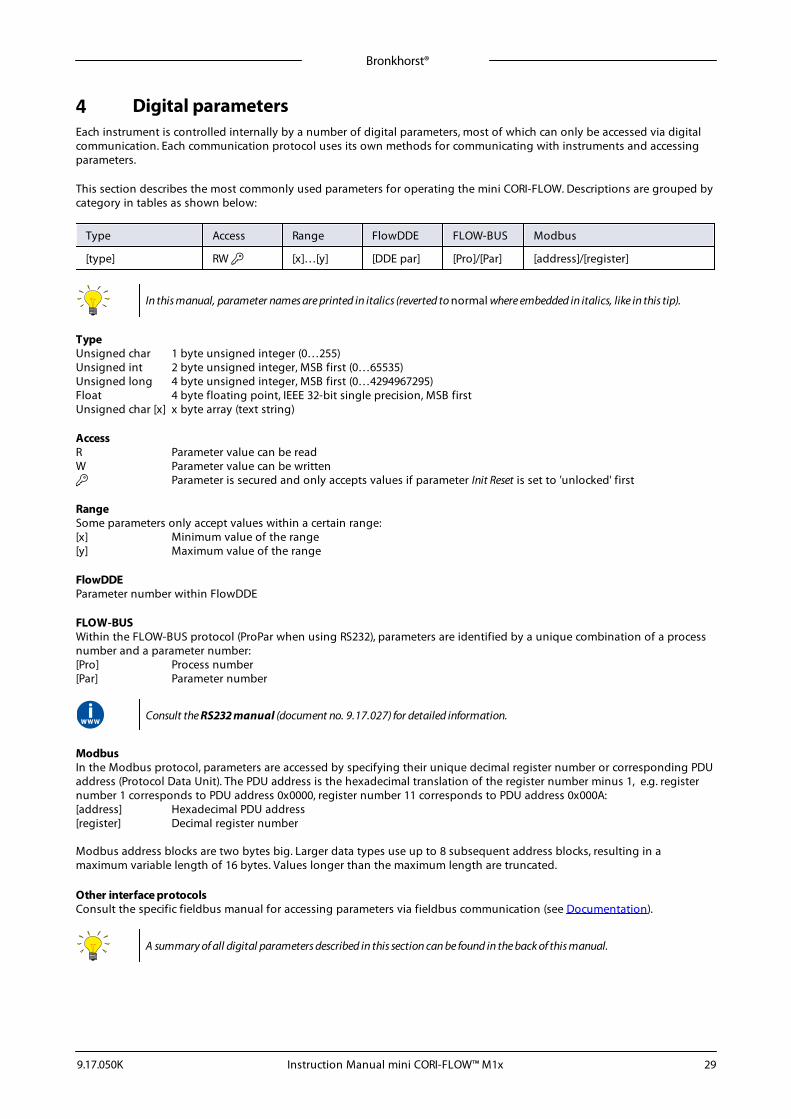
Bronkhorst®
Instruction Manual mini CORI-FLOW™ M1x9.17.050K 29
4 Digital parametersEach instrument is controlled internally by a number of digital parameters, most of which can only be accessed via digitalcommunication. Each communication protocol uses its own methods for communicating with instruments and accessingparameters.
This section describes the most commonly used parameters for operating the mini CORI-FLOW. Descriptions are grouped bycategory in tables as shown below:
Type Access Range FlowDDE FLOW-BUS Modbus
[type] RW [x]…[y] [DDE par] [Pro]/[Par] [address]/[register]
In this manual, parameter names are printed in italics (reverted to normal where embedded in italics, like in this tip).
TypeUnsigned char 1 byte unsigned integer (0…255)Unsigned int 2 byte unsigned integer, MSB first (0…65535)Unsigned long 4 byte unsigned integer, MSB first (0…4294967295)Float 4 byte floating point, IEEE 32-bit single precision, MSB firstUnsigned char [x] x byte array (text string)
AccessR Parameter value can be readW Parameter value can be written Parameter is secured and only accepts values if parameter Init Reset is set to 'unlocked' first
RangeSome parameters only accept values within a certain range:[x] Minimum value of the range[y] Maximum value of the range
FlowDDEParameter number within FlowDDE
FLOW-BUSWithin the FLOW-BUS protocol (ProPar when using RS232), parameters are identified by a unique combination of a processnumber and a parameter number:[Pro] Process number[Par] Parameter number
Consult the RS232 manual (document no. 9.17.027) for detailed information.
ModbusIn the Modbus protocol, parameters are accessed by specifying their unique decimal register number or corresponding PDUaddress (Protocol Data Unit). The PDU address is the hexadecimal translation of the register number minus 1, e.g. registernumber 1 corresponds to PDU address 0x0000, register number 11 corresponds to PDU address 0x000A:[address] Hexadecimal PDU address[register] Decimal register number
Modbus address blocks are two bytes big. Larger data types use up to 8 subsequent address blocks, resulting in amaximum variable length of 16 bytes. Values longer than the maximum length are truncated.
Other interface protocolsConsult the specific fieldbus manual for accessing parameters via fieldbus communication (see Documentation).
A summary of all digital parameters described in this section can be found in the back of this manual.

Bronkhorst®
Instruction Manual mini CORI-FLOW™ M1x 9.17.050K30
4.1 Measurement and control
Measure
Type Access Range FlowDDE FLOW-BUS Modbus
Unsigned int R 0…41942(65535*)
8 1/0 0x0020/33
This parameter indicates the flow metered by the instrument. The value of 32000 corresponds to 100%, the maximummeasured value output is 131.07%, which translates to 41942.
*In case the instrument is prepared for bi-directional measurement, the negative signals with an output range of -73.73…-0.003% are represented by the range of 41943…65535, whereas the positive signals 0…131.07% are stillrepresented by the range of 0…41942. (FlowDDE converts the numbers to negative values automatically).
Setpoint
Type Access Range FlowDDE FLOW-BUS Modbus
Unsigned int RW 0…32000 9 1/1 0x0021/34
This parameter is used to set the required flow rate for the controller. The signals have the same range as Measure, but thesetpoint range is limited between 0 and 100% (0…32000).
Temperature
Type Access Range FlowDDE FLOW-BUS Modbus
Float R -250…500 142 33/7 0xA138…0xA139/41273…41274
This parameter returns an indication of the actual media temperature in °C.
Pressure
Type Access Range FlowDDE FLOW-BUS Modbus
Float RW 0…3.4E+38 143 33/8 0xA140…0xA141/41281…41282
This parameter returns an indication of the actual (inlet) pressure in bar(a). By default the value of this parameter is equal toparameter Inlet pressure.
Density Actual
Type Access Range FlowDDE FLOW-BUS Modbus
Float R 0…3.4E+38 270 116/15 0xF400…0xF401/62465…62466
This parameter returns the actual density measured by the instrument. If the selected Capacity Unit is a volume flow type,the instrument uses this parameter for conversion of the measured mass flow to the selected unit.
4.1.1 Advanced measurement and controlFmeasure
Type Access Range FlowDDE FLOW-BUS Modbus
Float R -3.4E+38…3.4E+38
205 33/0 0xA100…0xA101/ 41217…41218
Floating point variant of Measure. Fmeasure shows the measured value in the capacity unit for which the instrument is set.The instrument uses parameters Capacity, Capacity 0%, Capacity Unit and Sensor Type to calculate Fmeasure.
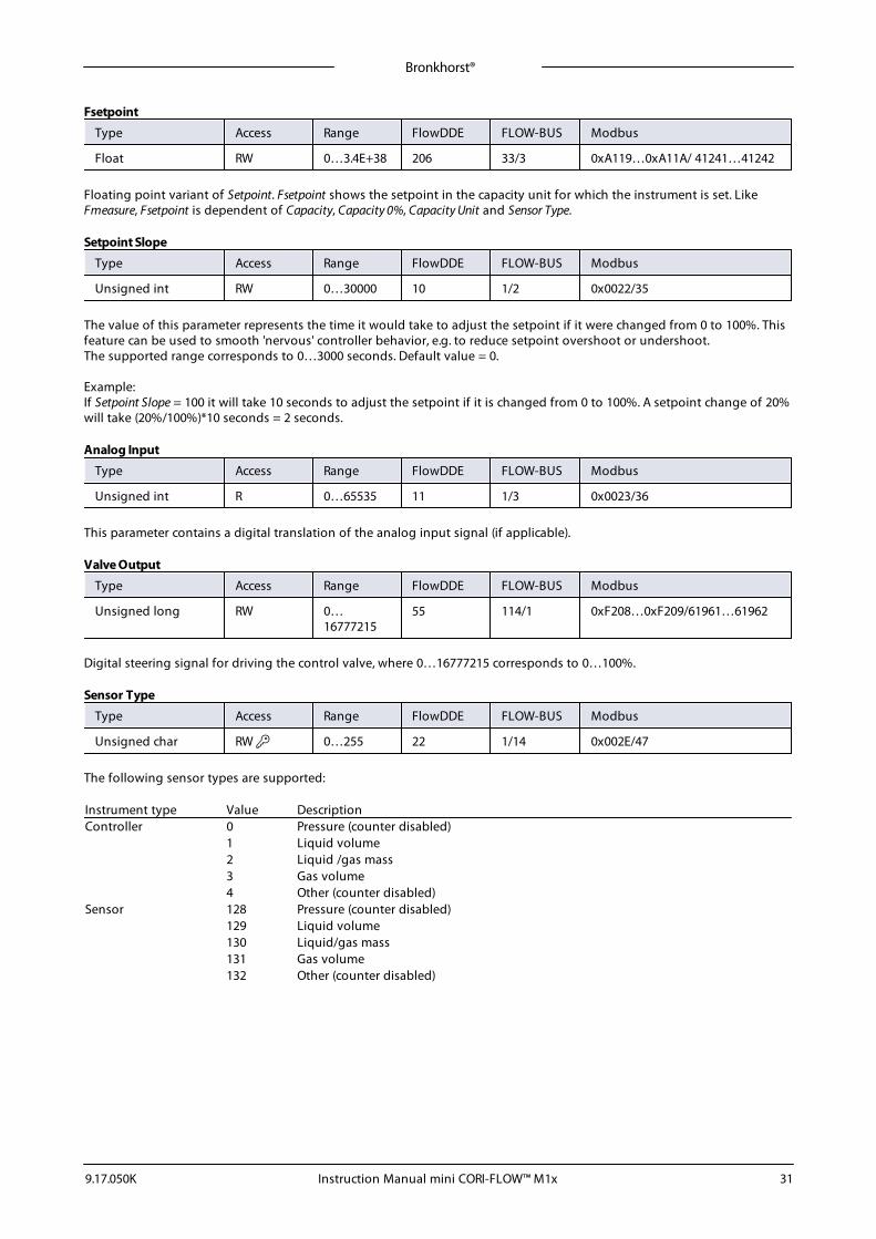
Bronkhorst®
Instruction Manual mini CORI-FLOW™ M1x9.17.050K 31
Fsetpoint
Type Access Range FlowDDE FLOW-BUS Modbus
Float RW 0…3.4E+38 206 33/3 0xA119…0xA11A/ 41241…41242
Floating point variant of Setpoint. Fsetpoint shows the setpoint in the capacity unit for which the instrument is set. LikeFmeasure, Fsetpoint is dependent of Capacity, Capacity 0%, Capacity Unit and Sensor Type.
Setpoint Slope
Type Access Range FlowDDE FLOW-BUS Modbus
Unsigned int RW 0…30000 10 1/2 0x0022/35
The value of this parameter represents the time it would take to adjust the setpoint if it were changed from 0 to 100%. Thisfeature can be used to smooth 'nervous' controller behavior, e.g. to reduce setpoint overshoot or undershoot.The supported range corresponds to 0…3000 seconds. Default value = 0.
Example:If Setpoint Slope = 100 it will take 10 seconds to adjust the setpoint if it is changed from 0 to 100%. A setpoint change of 20%will take (20%/100%)*10 seconds = 2 seconds.
Analog Input
Type Access Range FlowDDE FLOW-BUS Modbus
Unsigned int R 0…65535 11 1/3 0x0023/36
This parameter contains a digital translation of the analog input signal (if applicable).
Valve Output
Type Access Range FlowDDE FLOW-BUS Modbus
Unsigned long RW 0…16777215
55 114/1 0xF208…0xF209/61961…61962
Digital steering signal for driving the control valve, where 0…16777215 corresponds to 0…100%.
Sensor Type
Type Access Range FlowDDE FLOW-BUS Modbus
Unsigned char RW 0…255 22 1/14 0x002E/47
The following sensor types are supported:
Instrument type Value DescriptionController 0 Pressure (counter disabled)
1 Liquid volume2 Liquid /gas mass3 Gas volume4 Other (counter disabled)
Sensor 128 Pressure (counter disabled)129 Liquid volume130 Liquid/gas mass131 Gas volume132 Other (counter disabled)
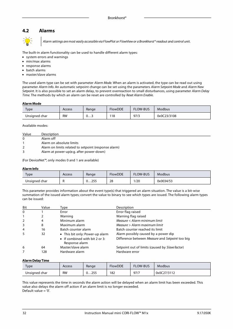
Bronkhorst®
Instruction Manual mini CORI-FLOW™ M1x 9.17.050K32
4.2 Alarms
Alarm settings are most easily accessible via FlowPlot or FlowView or a Bronkhorst® readout and control unit.
The built-in alarm functionality can be used to handle different alarm types:· system errors and warnings· min/max alarms· response alarms· batch alarms· master/slave alarms
The used alarm type can be set with parameter Alarm Mode. When an alarm is activated, the type can be read out usingparameter Alarm Info. An automatic setpoint change can be set using the parameters Alarm Setpoint Mode and Alarm NewSetpoint. It is also possible to set an alarm delay, to prevent overreaction to small disturbances, using parameter Alarm DelayTime. The methods by which an alarm can be reset are controlled by Reset Alarm Enable.
Alarm Mode
Type Access Range FlowDDE FLOW-BUS Modbus
Unsigned char RW 0…3 118 97/3 0x0C23/3108
Available modes:
Value Description0 Alarm off1 Alarm on absolute limits2 Alarm on limits related to setpoint (response alarm)3 Alarm at power-up(e.g. after power-down)
(For DeviceNet™, only modes 0 and 1 are available)
Alarm Info
Type Access Range FlowDDE FLOW-BUS Modbus
Unsigned char R 0…255 28 1/20 0x0034/53
This parameter provides information about the event type(s) that triggered an alarm situation. The value is a bit-wisesummation of the issued alarm types; convert the value to binary to see which types are issued. The following alarm typescan be issued:
Bit Value Type Description0 1 Error Error flag raised1 2 Warning Warning flag raised2 4 Minimum alarm Measure < Alarm minimum limit3 8 Maximum alarm Measure > Alarm maximum limit4 16 Batch counter alarm Batch counter reached its limit5 32 · This bit only: Power-up alarm Alarm possibly caused by a power dip
· If combined with bit 2 or 3:Response alarm
Difference between Measure and Setpoint too big
6 64 Master/slave alarm Setpoint out of limits (caused by Slave factor)7 128 Hardware alarm Hardware error
Alarm Delay Time
Type Access Range FlowDDE FLOW-BUS Modbus
Unsigned char RW 0…255 182 97/7 0x0C27/3112
This value represents the time in seconds the alarm action will be delayed when an alarm limit has been exceeded. Thisvalue also delays the alarm off action if an alarm limit is no longer exceeded.Default value = '0'.
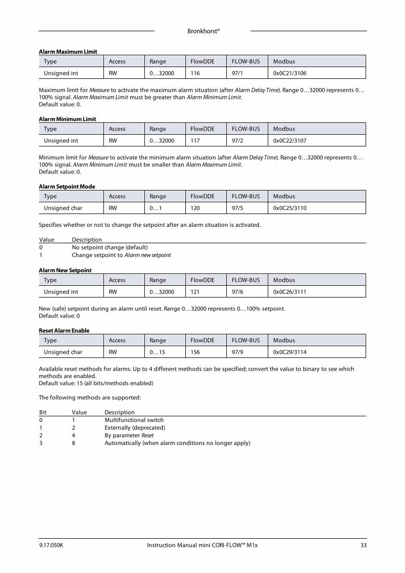
Bronkhorst®
Instruction Manual mini CORI-FLOW™ M1x9.17.050K 33
Alarm Maximum Limit
Type Access Range FlowDDE FLOW-BUS Modbus
Unsigned int RW 0…32000 116 97/1 0x0C21/3106
Maximum limit for Measure to activate the maximum alarm situation (after Alarm Delay Time). Range 0…32000 represents 0…100% signal. Alarm Maximum Limit must be greater than Alarm Minimum Limit.Default value: 0.
Alarm Minimum Limit
Type Access Range FlowDDE FLOW-BUS Modbus
Unsigned int RW 0…32000 117 97/2 0x0C22/3107
Minimum limit for Measure to activate the minimum alarm situation (after Alarm Delay Time). Range 0…32000 represents 0…100% signal. Alarm Minimum Limit must be smaller than Alarm Maximum Limit.Default value: 0.
Alarm Setpoint Mode
Type Access Range FlowDDE FLOW-BUS Modbus
Unsigned char RW 0…1 120 97/5 0x0C25/3110
Specifies whether or not to change the setpoint after an alarm situation is activated.
Value Description0 No setpoint change (default)1 Change setpoint to Alarm new setpoint
Alarm New Setpoint
Type Access Range FlowDDE FLOW-BUS Modbus
Unsigned int RW 0…32000 121 97/6 0x0C26/3111
New (safe) setpoint during an alarm until reset. Range 0…32000 represents 0…100% setpoint.Default value: 0
Reset Alarm Enable
Type Access Range FlowDDE FLOW-BUS Modbus
Unsigned char RW 0…15 156 97/9 0x0C29/3114
Available reset methods for alarms. Up to 4 different methods can be specified; convert the value to binary to see whichmethods are enabled.Default value: 15 (all bits/methods enabled)
The following methods are supported:
Bit Value Description0 1 Multifunctional switch1 2 Externally (deprecated)2 4 By parameter Reset3 8 Automatically (when alarm conditions no longer apply)
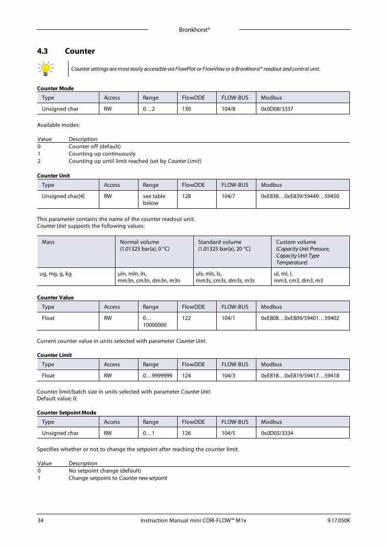
Bronkhorst®
Instruction Manual mini CORI-FLOW™ M1x 9.17.050K34
4.3 Counter
Counter settings are most easily accessible via FlowPlot or FlowView or a Bronkhorst® readout and control unit.
Counter Mode
Type Access Range FlowDDE FLOW-BUS Modbus
Unsigned char RW 0…2 130 104/8 0x0D08/3337
Available modes:
Value Description0 Counter off (default)1 Counting up continuously2 Counting up until limit reached (set by Counter Limit)
Counter Unit
Type Access Range FlowDDE FLOW-BUS Modbus
Unsigned char[4] RW see tablebelow
128 104/7 0xE838…0xE839/59449…59450
This parameter contains the name of the counter readout unit.Counter Unit supports the following values:
Mass Normal volume(1.01325 bar(a), 0 °C)
Standard volume(1.01325 bar(a), 20 °C)
Custom volume(Capacity Unit Pressure,Capacity Unit TypeTemperature)
ug, mg, g, kg uln, mln, ln,mm3n, cm3n, dm3n, m3n
uls, mls, ls,mm3s, cm3s, dm3s, m3s
ul, ml, l,mm3, cm3, dm3, m3
Counter Value
Type Access Range FlowDDE FLOW-BUS Modbus
Float RW 0…10000000
122 104/1 0xE808…0xE809/59401…59402
Current counter value in units selected with parameter Counter Unit.
Counter Limit
Type Access Range FlowDDE FLOW-BUS Modbus
Float RW 0…9999999 124 104/3 0xE818…0xE819/59417…59418
Counter limit/batch size in units selected with parameter Counter Unit.Default value: 0.
Counter Setpoint Mode
Type Access Range FlowDDE FLOW-BUS Modbus
Unsigned char RW 0…1 126 104/5 0x0D05/3334
Specifies whether or not to change the setpoint after reaching the counter limit.
Value Description0 No setpoint change (default)1 Change setpoint to Counter new setpoint

Bronkhorst®
Instruction Manual mini CORI-FLOW™ M1x9.17.050K 35
Counter New Setpoint
Type Access Range FlowDDE FLOW-BUS Modbus
Unsigned int RW 0…32000 127 104/6 0x0D06/3335
New (safe) setpoint when a counter limit is reached until reset. Range 0…32000 represents 0…100% setpoint.Default value: 0
Reset Counter Enable
Type Access Range FlowDDE FLOW-BUS Modbus
Unsigned char RW 0…15 157 104/9 0x0D09/3338
Available reset methods for counters. Up to 3 different methods can be specified. The value is a bit-wise summation of theenabled reset methods; convert the value to binary to see which methods are enabled.Default value: 7 (bits/methods 0, 1 and 2 enabled)
The following methods are supported:
Bit Value Description0 1 Micro-switch1 2 Externally2 4 By parameter Reset3 8 Automatically (e.g. when counter value is reset)
4.4 Network configuration
Changes made to the network settings will not be restored by a factory reset.
Default settingsNetwork configuration is done ex factory as indicated on the serial number label or in the technical specifications. The tablebelow shows the supported configurations for the available interface protocols (default settings are printed in boldface):
Protocol ProPar(RS232)
FLOW-BUS(RS485)
Modbus(RTU/ASCII)
PROFIBUS DP DeviceNet™
Bus Address 3 3…125 1…247 0…126 0…63
Baud Rate 9600192003840057600115200230400460800
187500400000
960019200384005600057600115200128000256000
(autodetect)960019200454509375018750050000015000003000000600000012000000
125000250000500000
Parity 0 0 0, 1, 2 2 0
Communication via fieldbus connection (top connector, RS485)Using the RS232 interface, set the following parameters to configure the instrument for communication via the fieldbusconnection:
Fieldbus 1 Address
Type Access Range FlowDDE FLOW-BUS Modbus
Unsigned char RW 0…255 199 125/10 0x0FAA/4011
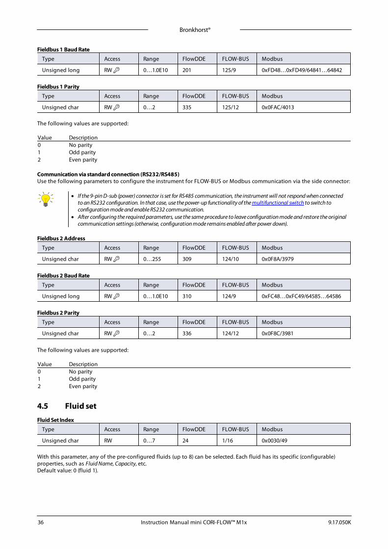
Bronkhorst®
Instruction Manual mini CORI-FLOW™ M1x 9.17.050K36
Fieldbus 1 Baud Rate
Type Access Range FlowDDE FLOW-BUS Modbus
Unsigned long RW 0…1.0E10 201 125/9 0xFD48…0xFD49/64841…64842
Fieldbus 1 Parity
Type Access Range FlowDDE FLOW-BUS Modbus
Unsigned char RW 0…2 335 125/12 0x0FAC/4013
The following values are supported:
Value Description0 No parity1 Odd parity2 Even parity
Communication via standard connection (RS232/RS485)Use the following parameters to configure the instrument for FLOW-BUS or Modbus communication via the side connector:
· If the 9-pin D-sub (power) connector is set for RS485 communication, the instrument will not respond when connectedto an RS232 configuration. In that case, use the power-up functionality of the multifunctional switch to switch toconfiguration mode and enable RS232 communication.
· After configuring the required parameters, use the same procedure to leave configuration mode and restore the originalcommunication settings (otherwise, configuration mode remains enabled after power down).
Fieldbus 2 Address
Type Access Range FlowDDE FLOW-BUS Modbus
Unsigned char RW 0…255 309 124/10 0x0F8A/3979
Fieldbus 2 Baud Rate
Type Access Range FlowDDE FLOW-BUS Modbus
Unsigned long RW 0…1.0E10 310 124/9 0xFC48…0xFC49/64585…64586
Fieldbus 2 Parity
Type Access Range FlowDDE FLOW-BUS Modbus
Unsigned char RW 0…2 336 124/12 0x0F8C/3981
The following values are supported:
Value Description0 No parity1 Odd parity2 Even parity
4.5 Fluid set
Fluid Set Index
Type Access Range FlowDDE FLOW-BUS Modbus
Unsigned char RW 0…7 24 1/16 0x0030/49
With this parameter, any of the pre-configured fluids (up to 8) can be selected. Each fluid has its specific (configurable)properties, such as Fluid Name, Capacity, etc.Default value: 0 (fluid 1).
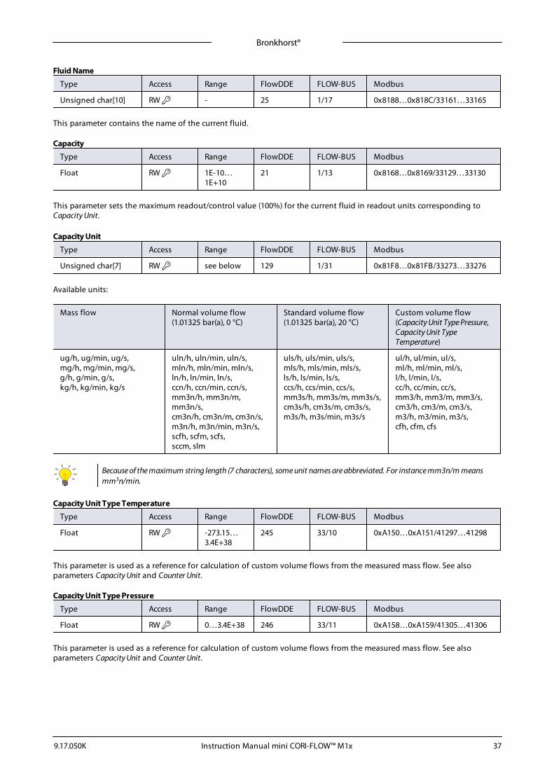
Bronkhorst®
Instruction Manual mini CORI-FLOW™ M1x9.17.050K 37
Fluid Name
Type Access Range FlowDDE FLOW-BUS Modbus
Unsigned char[10] RW - 25 1/17 0x8188…0x818C/33161…33165
This parameter contains the name of the current fluid.
Capacity
Type Access Range FlowDDE FLOW-BUS Modbus
Float RW 1E-10…1E+10
21 1/13 0x8168…0x8169/33129…33130
This parameter sets the maximum readout/control value (100%) for the current fluid in readout units corresponding toCapacity Unit.
Capacity Unit
Type Access Range FlowDDE FLOW-BUS Modbus
Unsigned char[7] RW see below 129 1/31 0x81F8…0x81FB/33273…33276
Available units:
Mass flow Normal volume flow(1.01325 bar(a), 0 °C)
Standard volume flow(1.01325 bar(a), 20 °C)
Custom volume flow(Capacity Unit Type Pressure,Capacity Unit TypeTemperature)
ug/h, ug/min, ug/s,mg/h, mg/min, mg/s,g/h, g/min, g/s,kg/h, kg/min, kg/s
uln/h, uln/min, uln/s,mln/h, mln/min, mln/s,ln/h, ln/min, ln/s,ccn/h, ccn/min, ccn/s,mm3n/h, mm3n/m,mm3n/s,cm3n/h, cm3n/m, cm3n/s,m3n/h, m3n/min, m3n/s,scfh, scfm, scfs,sccm, slm
uls/h, uls/min, uls/s,mls/h, mls/min, mls/s,ls/h, ls/min, ls/s,ccs/h, ccs/min, ccs/s,mm3s/h, mm3s/m, mm3s/s,cm3s/h, cm3s/m, cm3s/s,m3s/h, m3s/min, m3s/s
ul/h, ul/min, ul/s,ml/h, ml/min, ml/s,l/h, l/min, l/s,cc/h, cc/min, cc/s,mm3/h, mm3/m, mm3/s,cm3/h, cm3/m, cm3/s,m3/h, m3/min, m3/s,cfh, cfm, cfs
Because of the maximum string length (7 characters), some unit names are abbreviated. For instance mm3n/m meansmm3n/min.
Capacity Unit Type Temperature
Type Access Range FlowDDE FLOW-BUS Modbus
Float RW -273.15…3.4E+38
245 33/10 0xA150…0xA151/41297…41298
This parameter is used as a reference for calculation of custom volume flows from the measured mass flow. See alsoparameters Capacity Unit and Counter Unit.
Capacity Unit Type Pressure
Type Access Range FlowDDE FLOW-BUS Modbus
Float RW 0…3.4E+38 246 33/11 0xA158…0xA159/41305…41306
This parameter is used as a reference for calculation of custom volume flows from the measured mass flow. See alsoparameters Capacity Unit and Counter Unit.
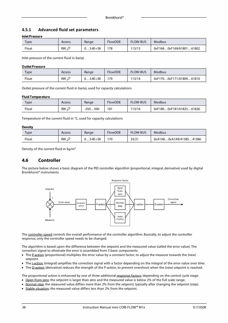
Bronkhorst®
Instruction Manual mini CORI-FLOW™ M1x 9.17.050K38
4.5.1 Advanced fluid set parametersInlet Pressure
Type Access Range FlowDDE FLOW-BUS Modbus
Float RW 0…3.4E+38 178 113/13 0xF168…0xF169/61801…61802
Inlet pressure of the current fluid in bar(a)
Outlet Pressure
Type Access Range FlowDDE FLOW-BUS Modbus
Float RW 0…3.4E+38 179 113/14 0xF170…0xF171/61809…61810
Outlet pressure of the current fluid in bar(a), used for capacity calculations
Fluid Temperature
Type Access Range FlowDDE FLOW-BUS Modbus
Float RW -250…500 181 113/16 0xF180…0xF181/61825…61826
Temperature of the current fluid in °C, used for capacity calculations
Density
Type Access Range FlowDDE FLOW-BUS Modbus
Float RW 0…3.4E+38 170 33/21 0xA1A8…0xA1A9/41385…41386
Density of the current fluid in kg/m3
4.6 ControllerThe picture below shows a basic diagram of the PID controller algorithm (proportional, integral, derivative) used by digitalBronkhorst® instruments.
The controller speed controls the overall performance of the controller algorithm. Basically, to adjust the controllerresponse, only the controller speed needs to be changed.
The algorithm is based upon the difference between the setpoint and the measured value (called the error value). Thecorrection signal to eliminate the error is assembled from 3 basic components:· The P-action (proportional) multiplies the error value by a constant factor, to adjust the measure towards the (new)
setpoint.· The I-action (integral) amplifies the correction signal with a factor depending on the integral of the error value over time.· The D-action (derivative) reduces the strength of the P-action, to prevent overshoot when the (new) setpoint is reached.
The proportional action is enhanced by one of three additional response factors, depending on the control cycle stage:· Open from zero: the setpoint is larger than zero and the measured value is below 2% of the full scale range.· Normal step: the measured value differs more than 2% from the setpoint, typically after changing the setpoint (step).· Stable situation: the measured value differs less than 2% from the setpoint.
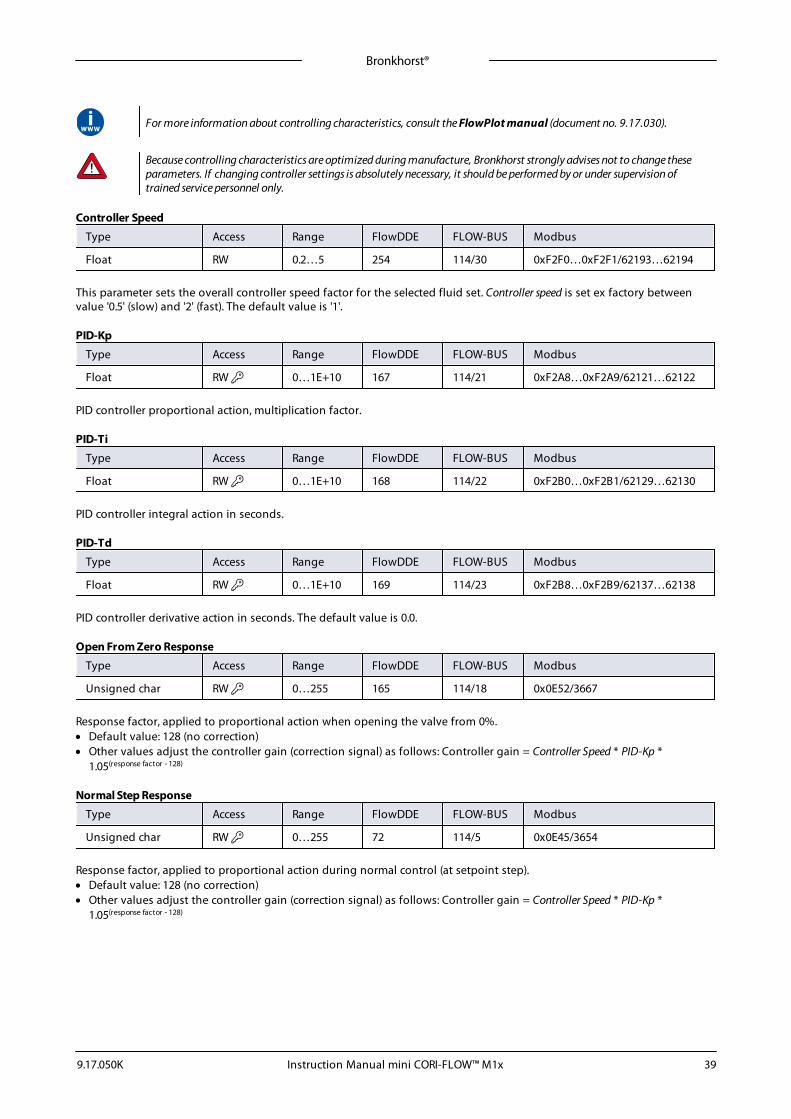
Bronkhorst®
Instruction Manual mini CORI-FLOW™ M1x9.17.050K 39
For more information about controlling characteristics, consult the FlowPlot manual (document no. 9.17.030).
Because controlling characteristics are optimized during manufacture, Bronkhorst strongly advises not to change theseparameters. If changing controller settings is absolutely necessary, it should be performed by or under supervision oftrained service personnel only.
Controller Speed
Type Access Range FlowDDE FLOW-BUS Modbus
Float RW 0.2…5 254 114/30 0xF2F0…0xF2F1/62193…62194
This parameter sets the overall controller speed factor for the selected fluid set. Controller speed is set ex factory betweenvalue '0.5' (slow) and '2' (fast). The default value is '1'.
PID-Kp
Type Access Range FlowDDE FLOW-BUS Modbus
Float RW 0…1E+10 167 114/21 0xF2A8…0xF2A9/62121…62122
PID controller proportional action, multiplication factor.
PID-Ti
Type Access Range FlowDDE FLOW-BUS Modbus
Float RW 0…1E+10 168 114/22 0xF2B0…0xF2B1/62129…62130
PID controller integral action in seconds.
PID-Td
Type Access Range FlowDDE FLOW-BUS Modbus
Float RW 0…1E+10 169 114/23 0xF2B8…0xF2B9/62137…62138
PID controller derivative action in seconds. The default value is 0.0.
Open From Zero Response
Type Access Range FlowDDE FLOW-BUS Modbus
Unsigned char RW 0…255 165 114/18 0x0E52/3667
Response factor, applied to proportional action when opening the valve from 0%.· Default value: 128 (no correction)· Other values adjust the controller gain (correction signal) as follows: Controller gain = Controller Speed * PID-Kp *
1.05(response factor - 128)
Normal Step Response
Type Access Range FlowDDE FLOW-BUS Modbus
Unsigned char RW 0…255 72 114/5 0x0E45/3654
Response factor, applied to proportional action during normal control (at setpoint step).· Default value: 128 (no correction)· Other values adjust the controller gain (correction signal) as follows: Controller gain = Controller Speed * PID-Kp *
1.05(response factor - 128)
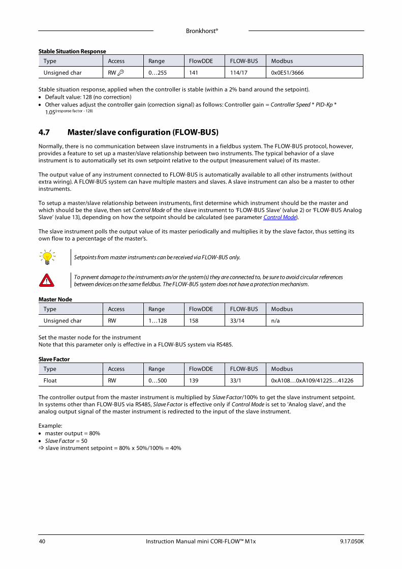
Bronkhorst®
Instruction Manual mini CORI-FLOW™ M1x 9.17.050K40
Stable Situation Response
Type Access Range FlowDDE FLOW-BUS Modbus
Unsigned char RW 0…255 141 114/17 0x0E51/3666
Stable situation response, applied when the controller is stable (within a 2% band around the setpoint).· Default value: 128 (no correction)· Other values adjust the controller gain (correction signal) as follows: Controller gain = Controller Speed * PID-Kp *
1.05(response factor - 128)
4.7 Master/slave configuration (FLOW-BUS)Normally, there is no communication between slave instruments in a fieldbus system. The FLOW-BUS protocol, however,provides a feature to set up a master/slave relationship between two instruments. The typical behavior of a slaveinstrument is to automatically set its own setpoint relative to the output (measurement value) of its master.
The output value of any instrument connected to FLOW-BUS is automatically available to all other instruments (withoutextra wiring). A FLOW-BUS system can have multiple masters and slaves. A slave instrument can also be a master to otherinstruments.
To setup a master/slave relationship between instruments, first determine which instrument should be the master andwhich should be the slave, then set Control Mode of the slave instrument to ‘FLOW-BUS Slave’ (value 2) or ‘FLOW-BUS AnalogSlave’ (value 13), depending on how the setpoint should be calculated (see parameter Control Mode).
The slave instrument polls the output value of its master periodically and multiplies it by the slave factor, thus setting itsown flow to a percentage of the master's.
Setpoints from master instruments can be received via FLOW-BUS only.
To prevent damage to the instruments an/or the system(s) they are connected to, be sure to avoid circular referencesbetween devices on the same fieldbus. The FLOW-BUS system does not have a protection mechanism.
Master Node
Type Access Range FlowDDE FLOW-BUS Modbus
Unsigned char RW 1…128 158 33/14 n/a
Set the master node for the instrumentNote that this parameter only is effective in a FLOW-BUS system via RS485.
Slave Factor
Type Access Range FlowDDE FLOW-BUS Modbus
Float RW 0…500 139 33/1 0xA108…0xA109/41225…41226
The controller output from the master instrument is multiplied by Slave Factor/100% to get the slave instrument setpoint.In systems other than FLOW-BUS via RS485, Slave Factor is effective only if Control Mode is set to 'Analog slave', and theanalog output signal of the master instrument is redirected to the input of the slave instrument.
Example:· master output = 80%· Slave Factor = 50 slave instrument setpoint = 80% x 50%/100% = 40%
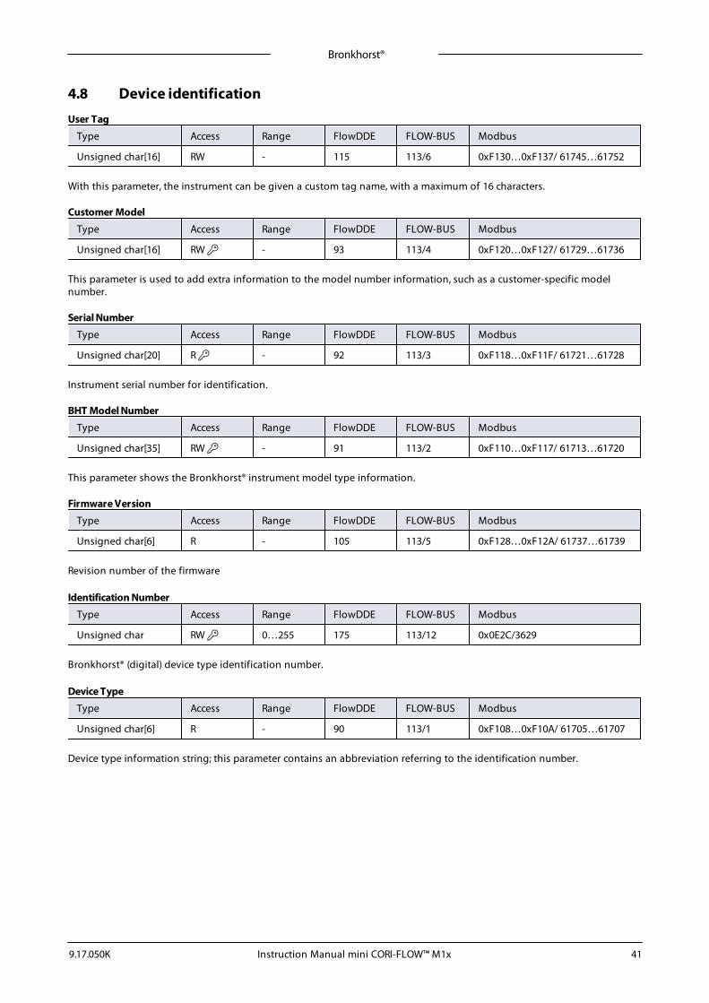
Bronkhorst®
Instruction Manual mini CORI-FLOW™ M1x9.17.050K 41
4.8 Device identification
User Tag
Type Access Range FlowDDE FLOW-BUS Modbus
Unsigned char[16] RW - 115 113/6 0xF130…0xF137/ 61745…61752
With this parameter, the instrument can be given a custom tag name, with a maximum of 16 characters.
Customer Model
Type Access Range FlowDDE FLOW-BUS Modbus
Unsigned char[16] RW - 93 113/4 0xF120…0xF127/ 61729…61736
This parameter is used to add extra information to the model number information, such as a customer-specific modelnumber.
Serial Number
Type Access Range FlowDDE FLOW-BUS Modbus
Unsigned char[20] R - 92 113/3 0xF118…0xF11F/ 61721…61728
Instrument serial number for identification.
BHT Model Number
Type Access Range FlowDDE FLOW-BUS Modbus
Unsigned char[35] RW - 91 113/2 0xF110…0xF117/ 61713…61720
This parameter shows the Bronkhorst® instrument model type information.
Firmware Version
Type Access Range FlowDDE FLOW-BUS Modbus
Unsigned char[6] R - 105 113/5 0xF128…0xF12A/ 61737…61739
Revision number of the firmware
Identification Number
Type Access Range FlowDDE FLOW-BUS Modbus
Unsigned char RW 0…255 175 113/12 0x0E2C/3629
Bronkhorst® (digital) device type identification number.
Device Type
Type Access Range FlowDDE FLOW-BUS Modbus
Unsigned char[6] R - 90 113/1 0xF108…0xF10A/ 61705…61707
Device type information string; this parameter contains an abbreviation referring to the identification number.
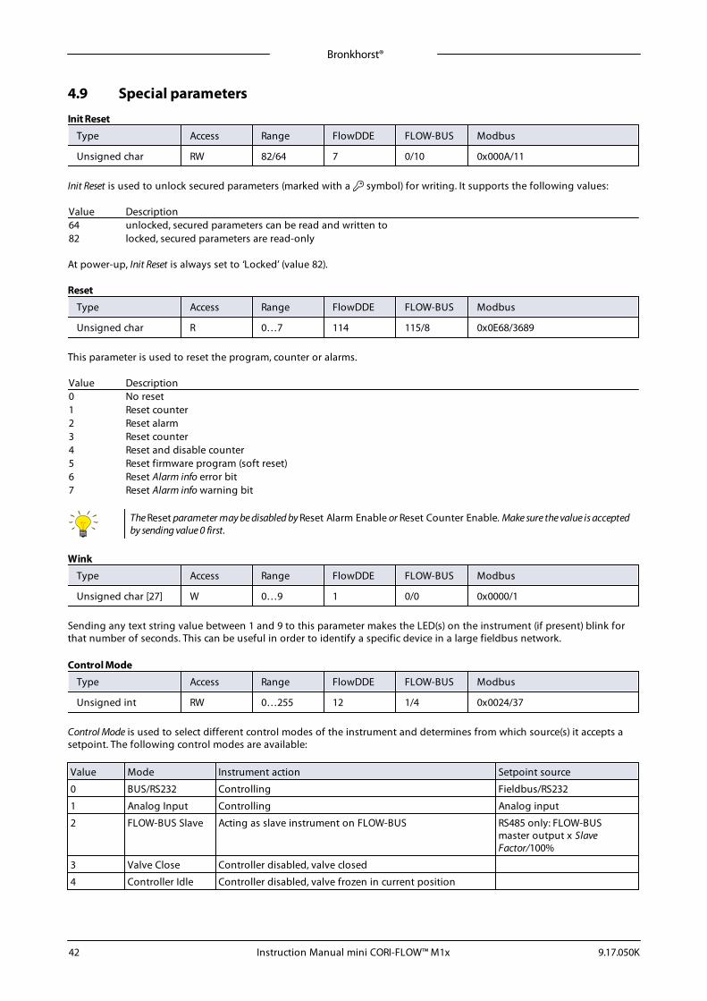
Bronkhorst®
Instruction Manual mini CORI-FLOW™ M1x 9.17.050K42
4.9 Special parameters
Init Reset
Type Access Range FlowDDE FLOW-BUS Modbus
Unsigned char RW 82/64 7 0/10 0x000A/11
Init Reset is used to unlock secured parameters (marked with a symbol) for writing. It supports the following values:
Value Description64 unlocked, secured parameters can be read and written to82 locked, secured parameters are read-only
At power-up, Init Reset is always set to ‘Locked’ (value 82).
Reset
Type Access Range FlowDDE FLOW-BUS Modbus
Unsigned char R 0…7 114 115/8 0x0E68/3689
This parameter is used to reset the program, counter or alarms.
Value Description0 No reset1 Reset counter2 Reset alarm3 Reset counter4 Reset and disable counter5 Reset firmware program (soft reset)6 Reset Alarm info error bit7 Reset Alarm info warning bit
The Reset parameter may be disabled by Reset Alarm Enable or Reset Counter Enable. Make sure the value is acceptedby sending value 0 first.
Wink
Type Access Range FlowDDE FLOW-BUS Modbus
Unsigned char [27] W 0…9 1 0/0 0x0000/1
Sending any text string value between 1 and 9 to this parameter makes the LED(s) on the instrument (if present) blink forthat number of seconds. This can be useful in order to identify a specific device in a large fieldbus network.
Control Mode
Type Access Range FlowDDE FLOW-BUS Modbus
Unsigned int RW 0…255 12 1/4 0x0024/37
Control Mode is used to select different control modes of the instrument and determines from which source(s) it accepts asetpoint. The following control modes are available:
Value Mode Instrument action Setpoint source
0 BUS/RS232 Controlling Fieldbus/RS232
1 Analog Input Controlling Analog input
2 FLOW-BUS Slave Acting as slave instrument on FLOW-BUS RS485 only: FLOW-BUSmaster output x SlaveFactor/100%
3 Valve Close Controller disabled, valve closed
4 Controller Idle Controller disabled, valve frozen in current position
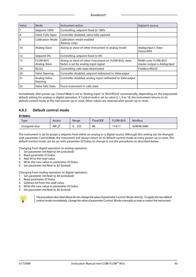
Bronkhorst®
Instruction Manual mini CORI-FLOW™ M1x9.17.050K 43
Value Mode Instrument action Setpoint source
7 Setpoint 100% Controlling, setpoint fixed to 100%
8 Valve Fully Open Controller disabled, valve fully opened
9 Calibration Mode Calibration mode enabled(factory only)
10 Analog Slave Acting as slave of other instrument in analog mode Analog Input x SlaveFactor/00%
12 Setpoint 0% Controlling, setpoint fixed to 0%
13 FLOW-BUSAnalog Slave
Acting as slave of other instrument on FLOW-BUS, slavefactor is set by analog input signal
RS485 only: FLOW-BUSmaster output x Analog Input
18 RS232 Controlling, safe state deactivated Fieldbus/RS232
20 Valve Steering Controller disabled, setpoint redirected to Valve output
21 Analog ValveSteering
Controller disabled, analog input redirected to Valve output
22 Valve Safe State Force instrument in safe state
Immediately after power-up, Control Mode is set to 'Analog input’ or ‘BUS/RS232’ automatically, depending on the (requested)default setting for analog or digital operation. If Control mode is set to value 0, 1, 9 or 18, the instrument returns to itsdefault control mode at the next power-up or reset. Other values are retained after power-up or reset.
4.9.1 Default control modeIO Status
Type Access Range FlowDDE FLOW-BUS Modbus
Unsigned char RW 0…255 86 114/11 0x0E4B/3660
The instrument is set to accept a setpoint from either an analog or a digital source. Although this setting can be changedwith parameter Control Mode, the instrument will always return to its default control mode at every power-up or reset. Thedefault control mode can be set with parameter IO Status; to change it, use the procedures as described below.
Changing from digital operation to analog operation:1. Set parameter Init Reset to 64 (unlocked)2. Read parameter IO Status3. Add 64 to the read value4. Write the new value to parameter IO Status5. Set parameter Init Reset to 82 (locked)
Changing from analog operation to digital operation:1. Set parameter Init Reset to 64 (unlocked)2. Read parameter IO Status3. Subtract 64 from the read value4. Write the new value to parameter IO Status5. Set parameter Init Reset to 82 (locked)
The procedures described above do not change the value of parameter Control Mode directly. To apply the new defaultcontrol mode immediately, change the value of parameter Control Mode manually or reset or restart the instrument.
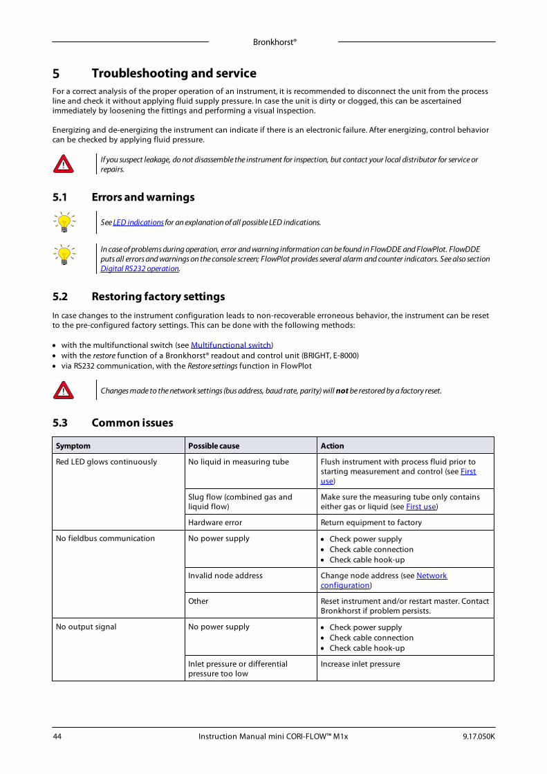
Bronkhorst®
Instruction Manual mini CORI-FLOW™ M1x 9.17.050K44
5 Troubleshooting and serviceFor a correct analysis of the proper operation of an instrument, it is recommended to disconnect the unit from the processline and check it without applying fluid supply pressure. In case the unit is dirty or clogged, this can be ascertainedimmediately by loosening the fittings and performing a visual inspection.
Energizing and de-energizing the instrument can indicate if there is an electronic failure. After energizing, control behaviorcan be checked by applying fluid pressure.
If you suspect leakage, do not disassemble the instrument for inspection, but contact your local distributor for service orrepairs.
5.1 Errors and warnings
See LED indications for an explanation of all possible LED indications.
In case of problems during operation, error and warning information can be found in FlowDDE and FlowPlot. FlowDDEputs all errors and warnings on the console screen; FlowPlot provides several alarm and counter indicators. See also sectionDigital RS232 operation.
5.2 Restoring factory settingsIn case changes to the instrument configuration leads to non-recoverable erroneous behavior, the instrument can be resetto the pre-configured factory settings. This can be done with the following methods:
· with the multifunctional switch (see Multifunctional switch)· with the restore function of a Bronkhorst® readout and control unit (BRIGHT, E-8000)· via RS232 communication, with the Restore settings function in FlowPlot
Changes made to the network settings (bus address, baud rate, parity) will not be restored by a factory reset.
5.3 Common issues
Symptom Possible cause Action
Red LED glows continuously No liquid in measuring tube Flush instrument with process fluid prior tostarting measurement and control (see Firstuse)
Slug flow (combined gas andliquid flow)
Make sure the measuring tube only containseither gas or liquid (see First use)
Hardware error Return equipment to factory
No fieldbus communication No power supply · Check power supply· Check cable connection· Check cable hook-up
Invalid node address Change node address (see Networkconfiguration)
Other Reset instrument and/or restart master. ContactBronkhorst if problem persists.
No output signal No power supply · Check power supply· Check cable connection· Check cable hook-up
Inlet pressure or differentialpressure too low
Increase inlet pressure
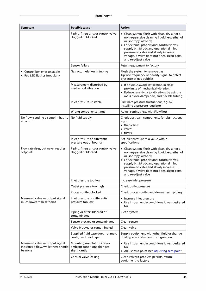
Bronkhorst®
Instruction Manual mini CORI-FLOW™ M1x9.17.050K 45
Symptom Possible cause Action
Piping, filters and/or control valveclogged or blocked
· Clean system (flush with clean, dry air or anon-aggressive cleaning liquid (e.g. ethanolor isopropyl alcohol)
· For external proportional control valves:supply 0…15 Vdc and operational inletpressure to valve and slowly increasevoltage. If valve does not open, clean partsand re-adjust valve
Sensor failure Return equipment to factory
· Control behavior unstable· Red LED flashes irregularly
Gas accumulation in tubing Flush the system to remove gasTip: use frequency or density signal to detectpresence of gas bubbles
Measurement disturbed bymechanical vibration
· If possible, avoid installation in closeproximity of mechanical vibration
· Reduce sensitivity to vibrations by using amass block, dampeners, and flexible tubing
Inlet pressure unstable Eliminate pressure fluctuations, e.g. byinstalling a pressure regulator
Wrong controller settings Adjust settings (e.g. with FlowPlot)
No flow (sending a setpoint has noeffect)
No fluid supply Check upstream components for obstruction,e.g.:· fluidic lines· valves· filters
Inlet pressure or differentialpressure out of bounds
Set inlet pressure to a value withinspecifications
Flow rate rises, but never reachessetpoint
Piping, filters and/or control valveclogged or blocked
· Clean system (flush with clean, dry air or anon-aggressive cleaning liquid (e.g. ethanolor isopropyl alcohol)
· For external proportional control valves:supply 0…15 Vdc and operational inletpressure to valve and slowly increasevoltage. If valve does not open, clean partsand re-adjust valve
Inlet pressure too low Increase inlet pressure
Outlet pressure too high Check outlet pressure
Process outlet blocked Check process outlet and downstream piping
Measured value or output signalmuch lower than setpoint
Inlet pressure or differentialpressure too low
· Increase inlet pressure· Use instrument in conditions it was designed
for
Piping or filters blocked orcontaminated
Clean system
Sensor blocked or contaminated Clean sensor
Valve blocked or contaminated Clean valve
Supplied fluid type does not matchconfigured fluid type
Supply equipment with other fluid or changefluid type in instrument configuration
Measured value or output signalindicates a flow, while there shouldbe none
Mounting orientation and/orambient conditions changedsignificantly
· Use instrument in conditions it was designedfor
· Adjust zero point (see Adjusting zero point)
Control valve leaking Clean valve; if problem persists, returnequipment to factory

Bronkhorst®
Instruction Manual mini CORI-FLOW™ M1x 9.17.050K46
Symptom Possible cause Action
System leakage Check the system for leakage. Follow vendorinstructions when installing third partycomponents (e.g. adapters, tubing, valves)
Continuous maximum measuredvalue or output signal
Inlet pressure too high Check inlet pressure
Control valve (normally open)failure
Return equipment to factory
Sensor failure Return equipment to factory
Flow rate decreases gradually Condensation on measuring tube(might occur with NH3 and somehydrocarbons, such as C3H8, C4H10)
Increase media temperature to above ambientconditions
Measured flow rate erroneous Calibration status compromised Check calibration status
Bronkhorst®
Instruction Manual mini CORI-FLOW™ M1x9.17.050K 47
5.4 ServiceFor current information on Bronkhorst® and service addresses, please visit our website:
http://www.bronkhorst.com
Do you have any questions about our products? Our Sales Department will gladly assist you selecting the right product foryour application. Contact sales by e-mail:
For after-sales questions, our Customer Service Department is available with help and guidance.To contact CSD by e-mail:
No matter the time zone, our experts within the Support Group are available to answer your request immediately or ensureappropriate further action. Our experts can be reached at:
+31 859 02 18 66
Bronkhorst High-Tech B.V.Nijverheidsstraat 1ANL-7261 AK RuurloThe Netherlands
Bronkhorst®
Instruction Manual mini CORI-FLOW™ M1x 9.17.050K48
6 Returns
6.1 Removal and return instructionsWhen returning materials, always clearly describe the problem, and, if possible, the work to be done, in a covering letter.
Instrument handling:1. Purge all fluidic lines (if applicable)2. If toxic or dangerous fluids have been used, the instrument must be cleaned before shipping3. Disconnect all external cabling and tubing and remove the instrument from the process line4. If applicable, secure movable parts with appropriate transport safety materials, to prevent damage during
transportation5. The instrument must be at ambient temperature before packaging6. Insert the instrument into a plastic bag and seal the bag7. Place the bag in an appropriate shipping container; if possible, use the original packaging box
Add documentation:· Reason of return· Failure symptoms· Contaminated condition· Declaration on decontamination
It is absolutely required to notify the factory if toxic or dangerous fluids have been in contact with the device!This is to enable the factory to take sufficient precautionary measures to safeguard the staff in their repair department.
All instruments must be dispatched with a completely filled in 'Declaration on decontamination'. Instruments without thisdeclaration will not be accepted.
A safety information document containing a 'Declaration on decontamination' form (document no 9.17.032) can bedownloaded from the Service & Support section of the Bronkhorst website (www.bronkhorst.com).
Important:Clearly note, on top of the package, the customs clearance number of Bronkhorst High-Tech B.V.:
NL801989978B01
(only if applicable, otherwise contact your distributor for local arrangements.)
6.2 Disposal (end of lifetime)Within the scope of the European Union, manufacturers of electrical and electronic equipment (EEE) are bound to complywith the WEEE Directive (Waste Electrical and Electronic Equipment). As a consequence, Bronkhorst is obligated to offer itscustomers in the EU the possibility to return EEE for disposal once it has reached the end of its lifetime, and take allnecessary steps to dismantle it properly and recycle or re-use its components whenever possible.
All Bronkhorst® products that fall under the regime of the WEEE Directive (which is the majority) have animage of a crossed-out wheeled bin printed somewhere on the product (typically the serial number label). Ifyou wish to dispose of Bronkhorst® equipment bearing this symbol, you can simply return it in accordancewith the removal and return instructions, and Bronkhorst will take care of proper dismantlement andrecycling. In the covering letter, just mention that you are returning the product for disposal. Within the EU,returning products for disposal is of course free of charge (except for shipping and handling costs).
For customers outside the EU, local or national directives and/or legislation may apply to EEE disposal. Ifapplicable, consult local or national authorities to learn how to handle EEE properly in your area.
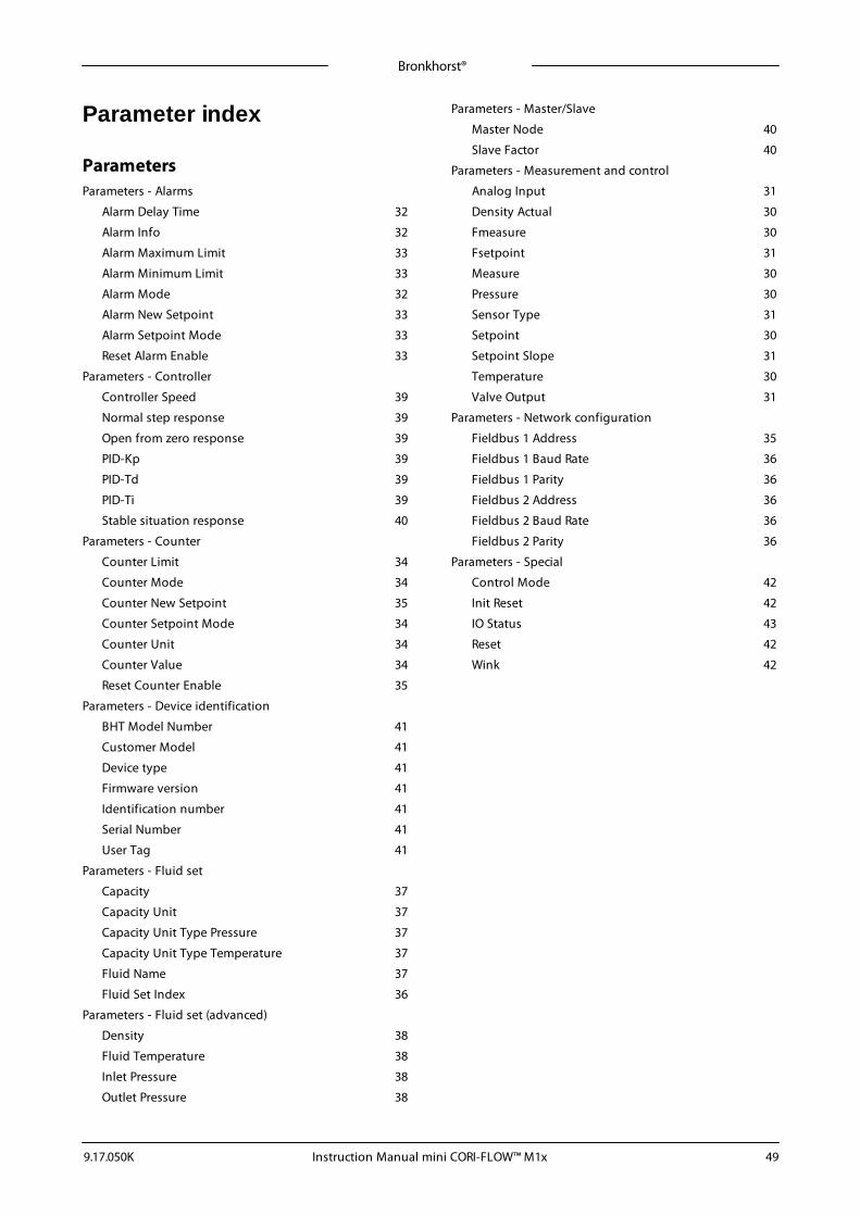
Bronkhorst®
Instruction Manual mini CORI-FLOW™ M1x9.17.050K 49
Parameter index
ParametersParameters - Alarms
Alarm Delay Time 32
Alarm Info 32
Alarm Maximum Limit 33
Alarm Minimum Limit 33
Alarm Mode 32
Alarm New Setpoint 33
Alarm Setpoint Mode 33
Reset Alarm Enable 33
Parameters - Controller
Controller Speed 39
Normal step response 39
Open from zero response 39
PID-Kp 39
PID-Td 39
PID-Ti 39
Stable situation response 40
Parameters - Counter
Counter Limit 34
Counter Mode 34
Counter New Setpoint 35
Counter Setpoint Mode 34
Counter Unit 34
Counter Value 34
Reset Counter Enable 35
Parameters - Device identification
BHT Model Number 41
Customer Model 41
Device type 41
Firmware version 41
Identification number 41
Serial Number 41
User Tag 41
Parameters - Fluid set
Capacity 37
Capacity Unit 37
Capacity Unit Type Pressure 37
Capacity Unit Type Temperature 37
Fluid Name 37
Fluid Set Index 36
Parameters - Fluid set (advanced)
Density 38
Fluid Temperature 38
Inlet Pressure 38
Outlet Pressure 38
Parameters - Master/Slave
Master Node 40
Slave Factor 40
Parameters - Measurement and control
Analog Input 31
Density Actual 30
Fmeasure 30
Fsetpoint 31
Measure 30
Pressure 30
Sensor Type 31
Setpoint 30
Setpoint Slope 31
Temperature 30
Valve Output 31
Parameters - Network configuration
Fieldbus 1 Address 35
Fieldbus 1 Baud Rate 36
Fieldbus 1 Parity 36
Fieldbus 2 Address 36
Fieldbus 2 Baud Rate 36
Fieldbus 2 Parity 36
Parameters - Special
Control Mode 42
Init Reset 42
IO Status 43
Reset 42
Wink 42