Mini cooper.pdf
32
Initial Print Date:09/01 Revision Date:05/03 Subject Page Climate Control ..................................................................................... 4 Refrigerant System ............................................................................. 5 Refrigerant .......................................................................................... 6 Compressor ........................................................................................ 6 Condenser .......................................................................................... 6 Receiver Drier ..................................................................................... 7 Evaporator .......................................................................................... 7 Expansion Valve .................................................................................. 7 Pressure Transducer ........................................................................... 8 Evaporator Temperature Sensor ......................................................... 8 Refrigerant System Principle of Operation ......................................... 9 Evaporation ........................................................................................ 9 Condensation ..................................................................................... 9 Compressor ....................................................................................... 10 Condenser ..........................................................................................10 Drier ................................................................................................... 11 Expansion Valve ................................................................................. 11 Heating System ..................................................................................... 12 IHKS Air Distribution ........................................................................... 13 Blower Motor and Resistor Pack ........................................................ 14 Control Flaps ...................................................................................... 15 Air Distribution Flaps ........................................................................... 16 Switch Panel IHKS................................................................................ 17 IHKS Control System Principle of Operation ..................................... 19 Air Distribution .................................................................................... 19 HRW ...................................................................................................19 HFS .................................................................................................... 19 Compressor Control ........................................................................... 20 Table of Contents Climate Control
Transcript of Mini cooper.pdf

Initial Print Date:09/01 Revision Date:05/03
Subject Page
Climate Control ..................................................................................... 4
Refrigerant System ............................................................................. 5Refrigerant .......................................................................................... 6Compressor ........................................................................................ 6Condenser .......................................................................................... 6Receiver Drier ..................................................................................... 7Evaporator .......................................................................................... 7Expansion Valve .................................................................................. 7Pressure Transducer ........................................................................... 8Evaporator Temperature Sensor ......................................................... 8
Refrigerant System Principle of Operation ......................................... 9Evaporation ........................................................................................ 9Condensation ..................................................................................... 9Compressor ....................................................................................... 10Condenser ..........................................................................................10Drier ................................................................................................... 11Expansion Valve ................................................................................. 11
Heating System ..................................................................................... 12IHKS Air Distribution ........................................................................... 13Blower Motor and Resistor Pack ........................................................ 14Control Flaps ...................................................................................... 15Air Distribution Flaps ........................................................................... 16
Switch Panel IHKS................................................................................ 17
IHKS Control System Principle of Operation ..................................... 19Air Distribution .................................................................................... 19HRW ...................................................................................................19HFS .................................................................................................... 19Compressor Control ........................................................................... 20
Table of Contents
Climate Control
2Climate Control
Subject Page
IHKA Heating and Air Distribution .......................................................21
Switch Panel IHKA ............................................................................... 21
IHKA Control System Principle of Operation ..................................... 26Temperature Control ............................................................................26Blower Control ....................................................................................26Air Distribution .................................................................................... 28Programmed Defrost .......................................................................... 29HFS/HRW ...........................................................................................29Compressor Control ...........................................................................29
IHKA On Board Diagnostics .................................................................30
Review Questions ..................................................................................32

3Climate Control
Climate Control
Model: All
Production: All
Objectives:
After completing this module you should be able to:
• Identify the different climate control systems.
• Understand the operation of the IHKS and IHKA.
• Recognize and know the location of major system components.
• Diagnosis basic Climate Control Faults.
4Climate Control
Climate Control
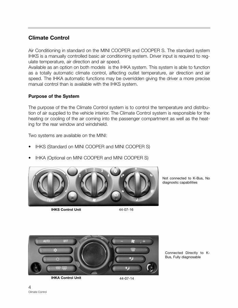
Air Conditioning in standard on the MINI COOPER and COOPER S. The standard systemIHKS is a manually controlled basic air conditioning system. Driver input is required to reg-ulate temperature, air direction and air speed.Available as an option on both models is the IHKA system. This system is able to functionas a totally automatic climate control, affecting outlet temperature, air direction and airspeed. The IHKA automatic functions may be overridden giving the driver a more precisemanual control than is available with the IHKS system.
Purpose of the System
The purpose of the the Climate Control system is to control the temperature and distribu-tion of air supplied to the vehicle interior. The Climate Control system is responsible for theheating or cooling of the air coming into the passenger compartment as well as the heat-ing for the rear window and windshield.
Two systems are available on the MINI:
• IHKS (Standard on MINI COOPER and MINI COOPER S)
• IHKA (Optional on MINI COOPER and MINI COOPER S)
Not connected to K-Bus, Nodiagnostic capabilities
IHKS Control Unit
Connected Directly to K-Bus, Fully diagnosable
IHKA Control Unit
44-07-16
44-07-14
5Climate Control
System Components
Both systems (IHKS and IHKA) consist of a refrigerant system, a heater system and a con-trol system. The refrigerant system is the same on both, the heater assembly and controlsystems are different.
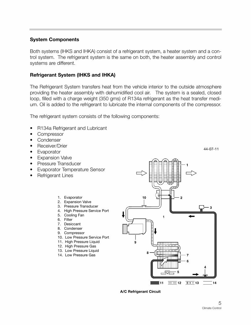
Refrigerant System (IHKS and IHKA)
The Refrigerant System transfers heat from the vehicle interior to the outside atmosphereproviding the heater assembly with dehumidified cool air. The system is a sealed, closedloop, filled with a charge weight (350 gms) of R134a refrigerant as the heat transfer medi-um. Oil is added to the refrigerant to lubricate the internal components of the compressor.
The refrigerant system consists of the following components:
• R134a Refrigerant and Lubricant• Compressor• Condenser• Receiver/Drier• Evaporator• Expansion Valve• Pressure Transducer• Evaporator Temperature Sensor• Refrigerant Lines
1. Evaporator2. Expansion Valve3. Pressure Transducer4. High Pressure Service Port5. Cooling Fan6. Filter7. Desiccant8. Condenser9. Compressor10. Low Pressure Service Port11. High Pressure Liquid12. High Pressure Gas13. Low Pressure Liquid14. Low Pressure Gas
A/C Refrigerant Circuit
44-07-11
6Climate Control
R134a RefrigerantAn air conditioning system uses refrigerant to absorb heat from the air that passes throughthe evaporator. Refrigerants are special materials that are vapors at room temperature andliquids at much lower temperatures. Automotive refrigerants boil at -16° F to -22° F (-27° Cto -30° C). Refrigerants are also able to contain and transport a large amount of heat, effi-ciently, and can be evaporated and condensed over and over without being damaged.In the air conditioning system, liquid refrigerant under high pressure flows through a smallhole into the evaporator, where the pressure is then greatly reduced. When the pressuredrops, the refrigerant boils and changes from a liquid to a vapor. As it changes its state, itabsorbs a large amount of heat.As the air passing through the evaporator gives up some of its heat, it becomes colder; itcan then be blown into the passenger compartment, to cool it.Once the refrigerant has absorbed heat from the air, it is returned to the compressor. TheA/C system removes the excess heat from the refrigerant as the refrigerant passes throughthe condenser.
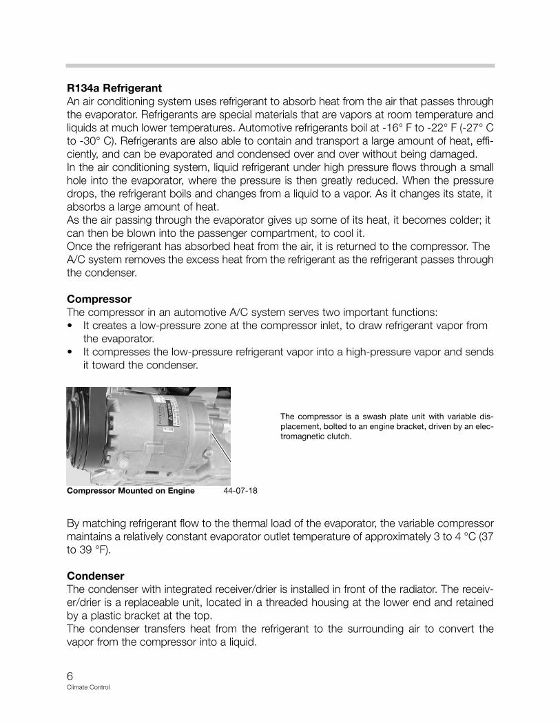
CompressorThe compressor in an automotive A/C system serves two important functions:• It creates a low-pressure zone at the compressor inlet, to draw refrigerant vapor from
the evaporator.• It compresses the low-pressure refrigerant vapor into a high-pressure vapor and sends
it toward the condenser.
By matching refrigerant flow to the thermal load of the evaporator, the variable compressormaintains a relatively constant evaporator outlet temperature of approximately 3 to 4 °C (37to 39 °F).
CondenserThe condenser with integrated receiver/drier is installed in front of the radiator. The receiv-er/drier is a replaceable unit, located in a threaded housing at the lower end and retainedby a plastic bracket at the top.The condenser transfers heat from the refrigerant to the surrounding air to convert thevapor from the compressor into a liquid.
Compressor Mounted on Engine
The compressor is a swash plate unit with variable dis-placement, bolted to an engine bracket, driven by an elec-tromagnetic clutch.
44-07-18
7Climate Control
Receiver/Drier
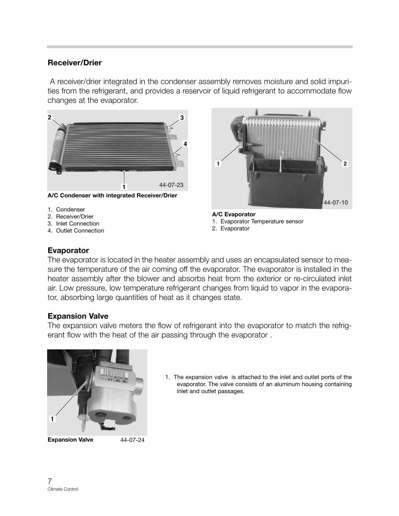
A receiver/drier integrated in the condenser assembly removes moisture and solid impuri-ties from the refrigerant, and provides a reservoir of liquid refrigerant to accommodate flowchanges at the evaporator.
EvaporatorThe evaporator is located in the heater assembly and uses an encapsulated sensor to mea-sure the temperature of the air coming off the evaporator. The evaporator is installed in theheater assembly after the blower and absorbs heat from the exterior or re-circulated inletair. Low pressure, low temperature refrigerant changes from liquid to vapor in the evapora-tor, absorbing large quantities of heat as it changes state.
Expansion ValveThe expansion valve meters the flow of refrigerant into the evaporator to match the refrig-erant flow with the heat of the air passing through the evaporator .
A/C Evaporator1. Evaporator Temperature sensor2. Evaporator
A/C Condenser with integrated Receiver/Drier
1. Condenser2. Receiver/Drier3. Inlet Connection4. Outlet Connection
Expansion Valve
1. The expansion valve is attached to the inlet and outlet ports of theevaporator. The valve consists of an aluminum housing containinginlet and outlet passages.
44-07-23
44-07-10
44-07-24

8Climate Control
Pressure TransducerThe Pressure Transducer is fitted into the high-pressure line between the condenser andthe expansion valve, on the drivers side rear of the engine compartment, under the battery.The pressure transducer signals EMS 2000 for compressor control and engine electriccooling fan operation.Because the compressor is lubricated by oil suspended in the refrigerant, the EMS 2000prevents operation of the compressor unless there is a minimum refrigerant pressure, andthus refrigerant and oil, in the system.When refrigerant pressure increases the EMS 2000 increases cooling fan speed to providemore airflow across the condenser.
Evaporator Temperature SensorThe Evaporator Temperature Sensor is located on the left side of the heater case and sig-nals directly to the BC1.The sensor is an encapsulated thermistor that provides the BC1 with an input of the evap-orator air outlet temperature.
Refrigerant LinesTo maintain similar flow velocities around the system, the diameter of the RefrigerantLines varies to suit the two-pressure/temperature conditions. The larger diameters areinstalled in the low pressure/temperature zone and the smaller diameters are installed in thehigh pressure/temperature zone. Low and high pressure service fittings are incorporatedinto the refrigerant lines for system servicing.
Pressure Transducer Evaporator Temperature Sensor
A/C Service FittingsA/C Lines at Condenser
44-07-36
44-07-09
44-07-24
44-07-35

9Climate Control
Principle of Operation
The basic principle at work in a climate control system is heat transfer. An automotive A/Csystem takes heat from inside the passenger compartment and transfers it outside.
In an A/C system, heat is transferred using a refrigerant. The refrigerant absorbs heat fromair entering the passenger compartment, carries the heat outside the compartment, releas-es the heat, and then re-enters the compartment to begin the cycle again.
An A/C system does not “add cold” to air - it removes some of the heat from it. Someheat is always present, but the less heat the air contains, the cooler it feels.
An air conditioning system’s efficiency is basedon how well it moves heat. Heat always travelsfrom warm to cold. The reverse is never true. Forexample, if a hot cup of coffee is left standing, itwill cool off, while a cold soda will get warm. Theheat from the warm coffee moves to the coolersurrounding air. The heat from the surroundingair moves to the cooler soda, until a balance isreached.
Temperature and State Changes
At sea level, water freezes at 32° F (0° C) and boils at 212° F (100° C). These are the tem-peratures at which water changes state. When a liquid boils (changes to a gas), it absorbsheat. When a gas condenses (changes back to a liquid), it gives off heat.• As the pressure on a liquid is increased, the boiling point rises.• As the pressure on a liquid is decreased, the boiling point drops.
EvaporationEvaporation is one of the basic principles by which a refrigeration system works. In evapo-ration, liquid changes to a vapor. Adding heat causes a liquid to evaporate.
CondensationCondensation is the reverse of evaporation. In condensation, a vapor changes to a liquid.Removing heat causes a vapor to condense to a liquid.
The task of an air conditioning system is to absorb a large amount of heat, move it awayfrom the passenger compartment, and exhaust it. When the refrigerant in the A/C systemevaporates, it absorbs a large amount of heat from the air entering the passenger com-partment.As the refrigerant vapor is pumped outside the passenger compartment, it transports thisheat with it. When the refrigerant condenses back into a liquid, this heat is released.
44-07-25

10Climate Control
Compressor
When AC is requested, the clutch is energized and the pulley drives the shaft.The journaland the swash plate turn with the shaft, and the angled swash plate produces reciprocat-ing movement of the pistons. Vapor from the inlet pressure chamber is drawn into the cylin-der, compressed, and discharged into the outlet pressure chamber, producing a flowaround the refrigerant circuit.
The flow rate through the compressor is determined by the length of the piston stroke,which is controlled by the tilt angle of the swash plate. The tilt angle of the swash plate iscontrolled by the servo pressure and compressor inlet pressure acting on the pistons dur-ing their induction stroke. A relative increase of inlet pressure over servo pressure movesthe pistons along their cylinders to increase the tilt angle, the piston stroke and the flowrate. Similarly, a relative decrease of inlet pressure over servo pressure moves the pistonsalong their cylinders to reduce the tilt angle, the piston stroke and the flow rate.
The control valve regulates the servo pressure in the crankcase as a function of inlet pres-sure, so that the flow rate of the compressor matches the thermal load at the evaporator,i.e. the more cooling required in the passenger compartment, the higher the thermal loadand flow rate. Servo pressure varies between inlet pressure and inlet pressure ±0.07 bar(±1psi).
As the refrigerant flows through the evaporator and absorbs heat (i.e. as the thermal loadincreases) the pressure of the vapor entering the compressor increases. In the control valve,the increased inlet pressure causes the diaphragm and push rod to close the ball valve. Theresulting reduction in crankcase pressure, together with the increase in inlet pressure,moves the swash plate to a higher tilt angle and increases the piston stroke and the flowthrough the compressor. When the thermal load of the evaporator decreases, the subse-quent decrease in pressure of vapor entering the compressor causes the control valve toopen. This increases swash plate crankcase pressure, which reduces the tilt angle of theswash plate and the flow through the compressor.
Condenser
The condenser, being directly downstream of the compressor, receives the high pressurevapor gas and the condensation process begins.The unit is classified as an integrated, sub-cooling condenser and consists of a fin and tubeheat exchanger installed between two end tanks. Divisions in the end tanks separate theheat exchanger into a three pass upper (condenser) section and a single pass lower (sub-cooler) section, which are interconnected by a receiver drier on the left hand end tank.Thereceiver/drier, containing a desiccant pack and filter, is a replaceable unit, located in athreaded housing at its lowest end and retained by a plastic bracket at the top of the con-denser.

11Climate Control
Ambient air, passing through the condenser due to ram effect and/or the cooling fan,absorbs heat from the refrigerant to change it from a vapor to a liquid. The condenser sec-tion cools and liquifies the refrigerant before it enters the receiver/drier.
Drier
From the condenser, liquid refrigerant under high pressure flows to the receiver/drier. Thedrier consists of a cylindrical tank to hold the refrigerant and a solid drier. The solid drier ismade from zeoliite, molecular sieves and aluminum oxides. The drier is designed to sepa-rate the refrigerant vapor from the liquid so that only the liquid is fed to the expansion valve.After the refrigerant has passed through the condenser the remaining gas in the refriger-ant liquifies and passes through the desiccant and filter removing moisture and solid impu-rities. The refrigerant flows into the sub-cooler section where it is further cooled resulting inthe refrigerant at the outlet being almost 100% liquid.
Expansion Valve and Evaporator
The refrigerant, now a high pressure liquid is passed via the refrigerant lines to the expan-sion valve at the entrance to the evaporator. A ball and spring metering valve is installed inthe inlet passage of the expansion valve. The metering valve is controlled by a temperaturesensitive tube connected to a diaphragm. The top of the diaphragm senses evaporator out-let pressure and the tube senses evaporator outlet temperature.
Liquid refrigerant flows through the metering valve into the evaporator. The restrictionacross the metering valve reduces the pressure and temperature of the refrigerant. Therestriction also changes the solid stream of refrigerant into a fine spray, to improve the evap-oration process. As the refrigerant passes through the evaporator, it absorbs heat from theair flowing through the evaporator. The increase in temperature causes the refrigerant tovaporize. The temperature and pressure of the refrigerant leaving the evaporator act on thediaphragm and temperature sensitive tube, which move to regulate the metering valveopening and so control the volume of refrigerant flowing through the evaporator . The moreheat available to evaporate refrigerant the greater the volume of refrigerant allowed throughthe metering valve.
The refrigerant, now a low pressure gas full of latent heat removed from the passengercompartment is drawn back into the compressor. The compressor again increases thepressure of the refrigerant, making it now a high pressure vapor. This pressure increaseraises the boiling point of the refrigerant, enabling it to give off heat and be condensed.

12Climate Control
Heating System
The heating and ventilation system controls the temperature and distribution of air suppliedto the vehicle interior. The system consists of a micro filter housing, a heater assembly, dis-tribution ducts, refrigerant system and a control panel. The MINI heater system uses the airblend principle: fresh air enters through vents beneath the windshield and flows into theheater assembly, a blend flap mixes the warm air passing the heat exchanger with the coolair and distributes it into the vehicle interior. Flow-through vents incorporated in the luggagecompartment enable the air to exit the vehicle interior.
Fresh or re-circulated air passes through the filter into the heater assembly where an elec-trical variable speed blower, and/or ram affect, forces the air through the system.Depending on the settings on the control panel, the air is then heated or cooled and sup-plied through the distribution ducts to face, defrost and floor level outlets.
Two different Heating Systems are provided depending on Climate Control variation (IHKSor IHKA).
Air Conditioning/Heating Assembly
1. Condenser2. Receiver/Drier3. Pressure Transducer4. Low Pressure Service Port5. High Pressure Service Port6. Control Panel7. Rear Footwell Air Ducts8. Compressor
44-07-05
13Climate Control
IHKS Heating and Air Distribution
The IHKS System allows manual selection of inlet air source, outlet air temperature, air dis-tribution and blower speed. Components of the IHKS heating and air distribution systeminclude:
• Microfilter• Heater Assembly (including Air Conditioning System)• Blower Motor and Resistor Pack• Heater Core• Control Flaps• Distribution Ducts• Outlet Vents
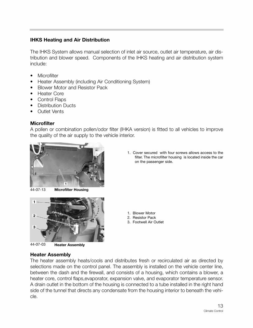
MicrofilterA pollen or combination pollen/odor filter (IHKA version) is fitted to all vehicles to improvethe quality of the air supply to the vehicle interior.
Heater AssemblyThe heater assembly heats/cools and distributes fresh or recirculated air as directed byselections made on the control panel. The assembly is installed on the vehicle center line,between the dash and the firewall, and consists of a housing, which contains a blower, aheater core, control flaps,evaporator, expansion valve, and evaporator temperature sensor. A drain outlet in the bottom of the housing is connected to a tube installed in the right handside of the tunnel that directs any condensate from the housing interior to beneath the vehi-cle.
1. Blower Motor2. Resistor Pack3. Footwell Air Outlet
Heater Assembly
1. Cover secured with four screws allows access to thefilter. The microfilter housing is located inside the caron the passenger side.
Microfilter Housing
44-07-03
44-07-13
14Climate Control
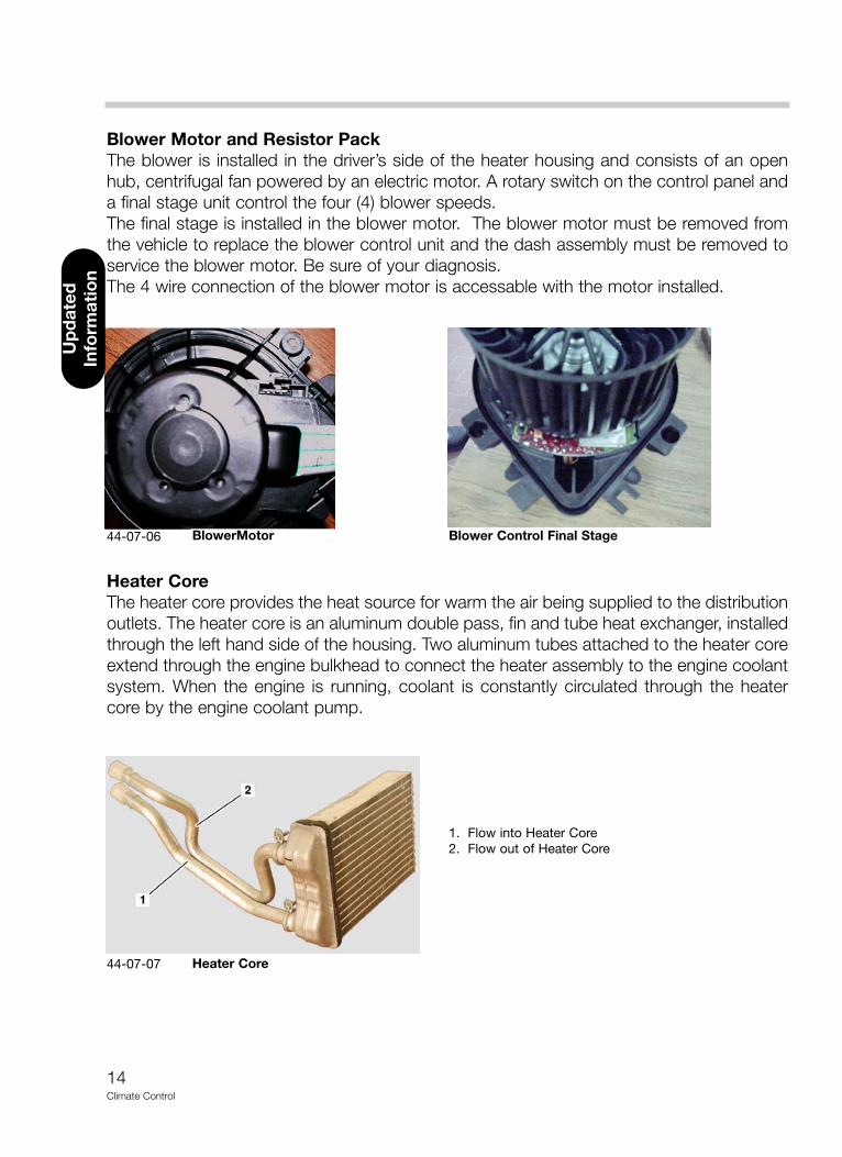
Blower Motor and Resistor PackThe blower is installed in the driver’s side of the heater housing and consists of an openhub, centrifugal fan powered by an electric motor. A rotary switch on the control panel anda final stage unit control the four (4) blower speeds. The final stage is installed in the blower motor. The blower motor must be removed fromthe vehicle to replace the blower control unit and the dash assembly must be removed toservice the blower motor. Be sure of your diagnosis.The 4 wire connection of the blower motor is accessable with the motor installed.
Heater CoreThe heater core provides the heat source for warm the air being supplied to the distributionoutlets. The heater core is an aluminum double pass, fin and tube heat exchanger, installedthrough the left hand side of the housing. Two aluminum tubes attached to the heater coreextend through the engine bulkhead to connect the heater assembly to the engine coolantsystem. When the engine is running, coolant is constantly circulated through the heatercore by the engine coolant pump.
1. Flow into Heater Core2. Flow out of Heater Core
Heater Core
BlowerMotor Blower Control Final Stage
44-07-07
44-07-06
Up
dat
ed
Info
rmat
ion
15Climate Control
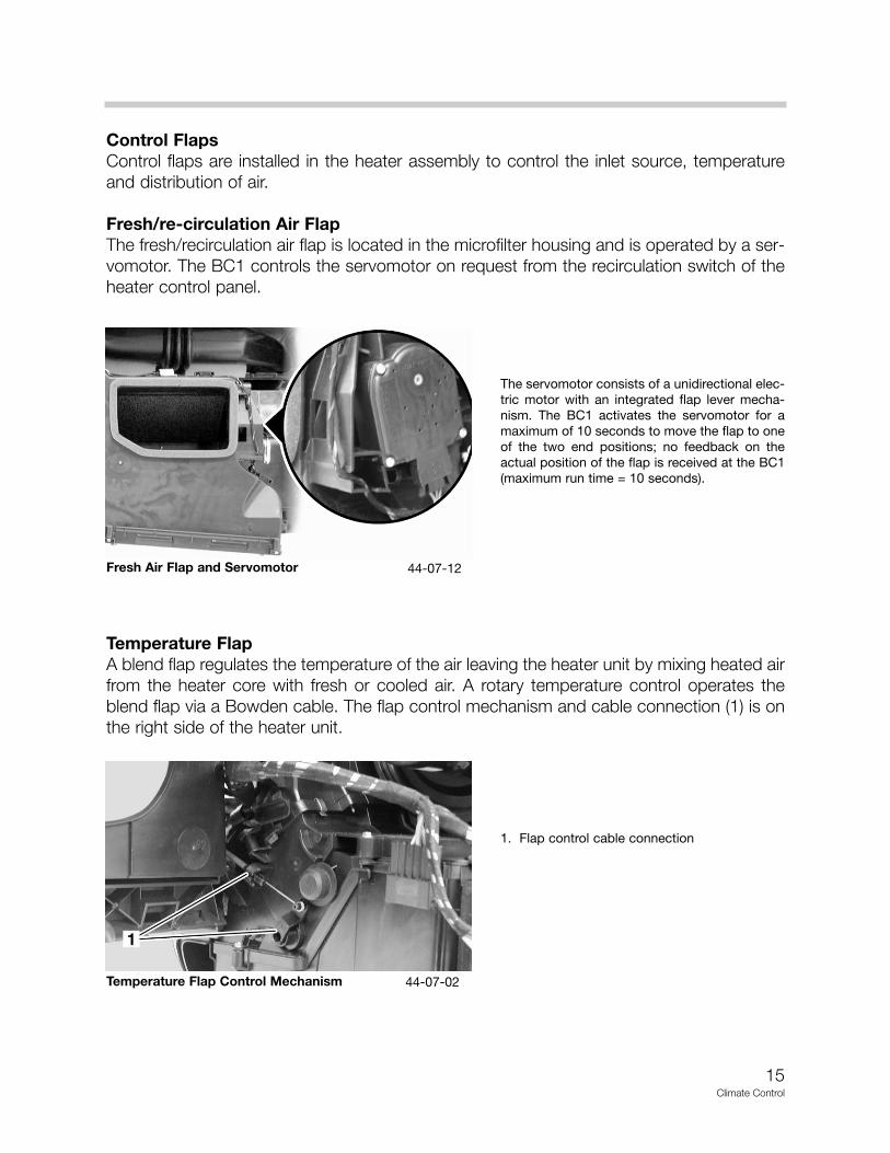
Control FlapsControl flaps are installed in the heater assembly to control the inlet source, temperatureand distribution of air.
Fresh/re-circulation Air FlapThe fresh/recirculation air flap is located in the microfilter housing and is operated by a ser-vomotor. The BC1 controls the servomotor on request from the recirculation switch of theheater control panel.
Temperature FlapA blend flap regulates the temperature of the air leaving the heater unit by mixing heated airfrom the heater core with fresh or cooled air. A rotary temperature control operates theblend flap via a Bowden cable. The flap control mechanism and cable connection (1) is onthe right side of the heater unit.
Fresh Air Flap and Servomotor
The servomotor consists of a unidirectional elec-tric motor with an integrated flap lever mecha-nism. The BC1 activates the servomotor for amaximum of 10 seconds to move the flap to oneof the two end positions; no feedback on theactual position of the flap is received at the BC1(maximum run time = 10 seconds).
1. Flap control cable connection
Temperature Flap Control Mechanism 44-07-02
44-07-12
16Climate Control
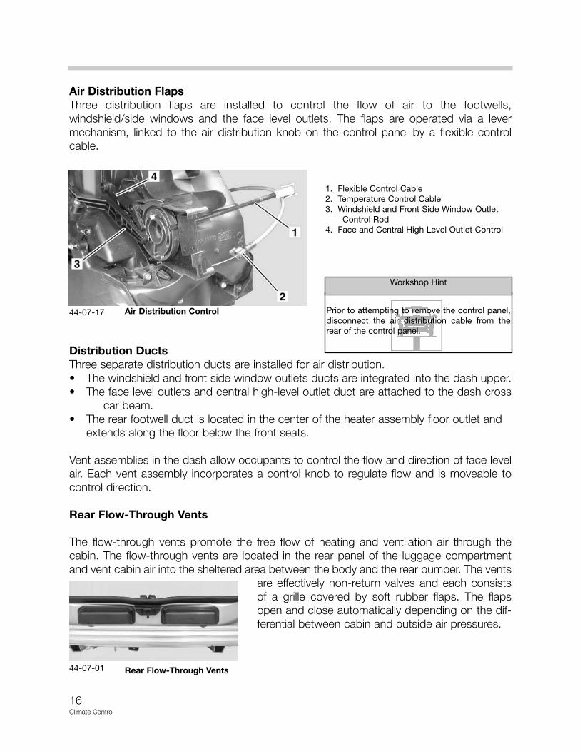
Air Distribution FlapsThree distribution flaps are installed to control the flow of air to the footwells,windshield/side windows and the face level outlets. The flaps are operated via a levermechanism, linked to the air distribution knob on the control panel by a flexible controlcable.
Distribution DuctsThree separate distribution ducts are installed for air distribution.• The windshield and front side window outlets ducts are integrated into the dash upper.• The face level outlets and central high-level outlet duct are attached to the dash cross
car beam.• The rear footwell duct is located in the center of the heater assembly floor outlet and
extends along the floor below the front seats.
Vent assemblies in the dash allow occupants to control the flow and direction of face levelair. Each vent assembly incorporates a control knob to regulate flow and is moveable tocontrol direction.
Rear Flow-Through Vents
The flow-through vents promote the free flow of heating and ventilation air through thecabin. The flow-through vents are located in the rear panel of the luggage compartmentand vent cabin air into the sheltered area between the body and the rear bumper. The vents
are effectively non-return valves and each consistsof a grille covered by soft rubber flaps. The flapsopen and close automatically depending on the dif-ferential between cabin and outside air pressures.
1. Flexible Control Cable2. Temperature Control Cable3. Windshield and Front Side Window Outlet
Control Rod4. Face and Central High Level Outlet Control
Air Distribution Control Prior to attempting to remove the control panel,disconnect the air distribution cable from therear of the control panel.
Workshop Hint
Rear Flow-Through Vents
44-07-17
44-07-01
17Climate Control
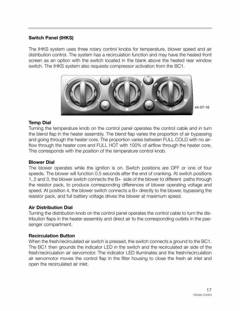
Switch Panel (IHKS)
The IHKS system uses three rotary control knobs for temperature, blower speed and airdistribution control. The system has a recirculation function and may have the heated frontscreen as an option with the switch located in the blank above the heated rear windowswitch. The IHKS system also requests compressor activation from the BC1.
Temp DialTurning the temperature knob on the control panel operates the control cable and in turnthe blend flap in the heater assembly. The blend flap varies the proportion of air bypassingand going through the heater core. The proportion varies between FULL COLD with no air-flow through the heater core and FULL HOT with 100% of airflow through the heater core.This corresponds with the position of the temperature control knob.
Blower DialThe blower operates while the ignition is on. Switch positions are OFF or one of fourspeeds. The blower will function 0.5 seconds after the end of cranking. At switch positions1, 2 and 3, the blower switch connects the B+ side of the blower to different paths throughthe resistor pack, to produce corresponding differences of blower operating voltage andspeed. At position 4, the blower switch connects a B+ directly to the blower, bypassing theresistor pack, and full battery voltage drives the blower at maximum speed.
Air Distribution DialTurning the distribution knob on the control panel operates the control cable to turn the dis-tribution flaps in the heater assembly and direct air to the corresponding outlets in the pas-senger compartment.
Recirculation ButtonWhen the fresh/recirculated air switch is pressed, the switch connects a ground to the BC1.The BC1 then grounds the indicator LED in the switch and the recirculated air side of thefresh/recirculation air servomotor. The indicator LED illuminates and the fresh/recirculationair servomotor moves the control flap in the filter housing to close the fresh air inlet andopen the recirculated air inlet.
44-07-16
18Climate Control
Compressor Button (Snowflake)The Compressor Button operates a ground input to the BC1 to control the on/off selectionof the refrigerant system. A green indicator LED in the AC switch illuminates when the airconditioning system is switched on.
Heated Rear Window Button (HRW)A momentary push switch controls the heated rear window and incorporates an orangeLED to indicate status. A single press of the switch will turn the heated rear window on, illu-minate the LED, and start a timer. When the timer has expired, the heated rear window andLED will turn off. The HRW is controlled by the BC1.
Heated Front Windshield (HFS)The heated front screen switch is located on the control panel above the heated rear win-dow switch. The operation and configuration of the heated front screen control is identicalto the heated rear window control.
IHKS Control Unit
The IHKS System is a manual climate control. Operator input controls air temperature, airdistribution, blower speeds and compressor requests. There are no “Automatic” func-tions with IHKS.
Temperature ControlThe operator controls air outlet temperature by positioning the temperature knob. The knobcontrols the cable to the blend flap.The flap is linked internally to a secondary air-directionflap that optimizes airflow through the unit by ensuring the airflow does not enter the heatercore area thereby preventing any unwanted hot/cold air bleed. Engine coolant is flowing constantly through the heater core. There is no water valve.Failure of the flap to block off air flow through the heater core would provide constant heat-ed air in the vehicle.
Blower Control
The Blower may only run if the ignition is on. There is a 0.5 second delay after enginecranking to energize the blower. This delay is controlled by the BC1. The BC1 receives theend of cranking (engine started) signal from the EMS2000. After a 0.5 second delay theBC1 energizes the Blower Relay. The Blower Relay supplies power to the 5 position blow-er switch (Off, 1, 2, 3, 4). Activation of the blower switch creates a power flow through theresistor pack (except in position 4). The varying voltage from the resistor pack is suppliedto the blower and the BC1. The blower speed is based on the voltage supply from theresistor pack. Less resistance means higher voltage and higher blower speed. The BC1looks for the blower speed voltage before requesting the AC compressor. Loss of blowervoltage will result in loss of compressor.
19Climate Control
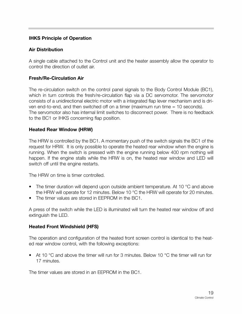
IHKS Principle of Operation
Air Distribution
A single cable attached to the Control unit and the heater assembly allow the operator tocontrol the direction of outlet air.
Fresh/Re-Circulation Air
The re-circulation switch on the control panel signals to the Body Control Module (BC1),which in turn controls the fresh/re-circulation flap via a DC servomotor. The servomotorconsists of a unidirectional electric motor with a integrated flap lever mechanism and is dri-ven end-to-end, and then switched off on a timer (maximum run time = 10 seconds).The servomotor also has internal limit switches to disconnect power. There is no feedbackto the BC1 or IHKS concerning flap position.
Heated Rear Window (HRW)
The HRW is controlled by the BC1. A momentary push of the switch signals the BC1 of therequest for HRW. It is only possible to operate the heated rear window when the engine isrunning. When the switch is pressed with the engine running below 400 rpm nothing willhappen. If the engine stalls while the HRW is on, the heated rear window and LED willswitch off until the engine restarts.
The HRW on time is timer controlled.
• The timer duration will depend upon outside ambient temperature. At 10 °C and abovethe HRW will operate for 12 minutes. Below 10 °C the HRW will operate for 20 minutes.
• The timer values are stored in EEPROM in the BC1.
A press of the switch while the LED is illuminated will turn the heated rear window off andextinguish the LED.
Heated Front Windshield (HFS)
The operation and configuration of the heated front screen control is identical to the heat-ed rear window control, with the following exceptions:
• At 10 °C and above the timer will run for 3 minutes. Below 10 °C the timer will run for 17 minutes.
The timer values are stored in an EEPROM in the BC1.

20Climate Control
Compressor Control
The Compressor is directly controlled by the EMS2000 through a compressor relay.When a request is received at the IHKS for compressor activation, a signal is sent to theBC1. The BC1 looks at blower status (output from the blower resistor pack) and evapora-tor temperature. If the blower is operational and the evaporator temperature is above 20oC,the BC1 changes the Compressor “OFF” signal it sends to the EMS2000 to a Compressor“ON” signal.The Compressor “ON” signal is sent via the K-Bus through the IKE over the CAN Bus tothe EMS2000. When this “ON” signal is received by the EMS2000, it checks the status ofthe pressure transducer, and if the transducer is in operating range (1.6 - 30 Bar) the com-pressor clutch relay is energized.The BC1 is advised of the compressor activation (or no activation) and the illumination inthe compressor request button of the IHKS remains illuminated. (No activation causes theLED to flash.)Hard acceleration can cause the compressor clutch to be disengaged. After three occur-rences in a single ignition cycle the ECM 2000 disregards further hard acceleration occur-rences and leaves the compressor clutch engaged.The air conditioning will be automatically suspended if:• The engine speed is above 6016 rpm.• The evaporator temperature falls below 2 °C - to prevent freezing.• The coolant temperature goes above 118 °C - to protect the engine.• The AC system pressure goes above 30 Bar - to protect the system.• The AC system pressure goes below 1.6 Bar - to protect the system.• The accelerator pedal is fully depressed (continuous full pedal demand) for more than 5
seconds.• The accelerator pedal is depressed rapidly (instantaneous full pedal demand) for more
than 2 seconds.• The engine speed is below 500 rpm (engine stall).
IIHHKKSS CCoommpprreessssoorr CCoonnttrrooll
44-07-25

21Climate Control
IHKA Heating and Air Distribution
The Heating and Air Distribution of IHKA systems differ from the IHKS system in the fol-lowing ways;
• Two servomotors controlled by the IHKA module operate the temperature blend flap and air distribution mechanism. Flap position is monitored by the IHKA using poten-tiometers integrated in the servomotors.
• A heater core sensor measures the temperature of the air coming off the heat exchang-er. The sensor is located on the right side of the front of the heater unit.
• A rocker switch and a power transistor (final stage) controls the blower motor at eight speeds. The blower speed is controlled manually via the rocker switch or automaticallyin the AUTO mode.
Switch Panel (IHKA)
An integral control panel on the IHKA module contains switches for system control inputsand a display to provide system status information.The IHKA control system controls the operation of the refrigerant system and the controlflaps in the heater assembly to control the temperature and distribution of air in the vehicleinterior. It also outputs signals to the BC1 to control the fresh/re-circulation air servomotorand to the blower to control the air volume.
1
IHKA Temperature Control
1. Blower Transistor Pack (Final Stage)Final Stage moved to Blower Assy
2. Temperature Blend Flap Servo Motor
IHKA Air Distribution
1. IHKA Air Distribution Servo Motor
44-07-2244-07-21
Up
dat
ed
Info
rmat
ion

22Climate Control
Display
The Display integrated into the IHKA will provide current temperature setting and fan speedinformation. The display will show LO or HI at the extreme temperature settings and indi-cate fan speed by the number of streamers illuminated around the fan blade. It is possibleto display the temperature in 0C or 0F, changeable at the control unit.
Blower Switch
The blower speed control is adjusted by a horizontal rocker switch, with + and - on theright and left respectively. This switch provides manual control of blower speed.There are eight blower speeds. Each press of the blower switch will adjust the blowerspeed by one speed step in the appropriate direction. Pressing and holding the control willcause the fan speed to change every 0.8 seconds, until the control is released or themaximum or minimum speed is reached.Blower speed will be indicated by a series of "streamer effect" bars arranged around thetop edge of the central display panel. Each bar represents one speed step; eight bars arevisible at maximum blower speed.
1. Display2. Blower Switch3. Defrost Switch4. Face Distribution5. Interior Temperature Sensor6. Foot Distribution7. Temperature Control Switch8. HFS/HRW Switch
(Depending on option)9. Fresh Air/Re-Circulation Switch10. AC Compressor Switch11. Auto/Off Switch
IHKA Control Unit
IHKA Contol Unit Diplay Minimum Temperature Max Blower Speed
IHKA Contol Unit Diplay 220C Blower Speed 3
44-07-31
44-07-15
44-07-30

23Climate Control
Blower speed will be controlled automatically if AUTO is selected. The blower will function0.5 seconds after the end of cranking. If a problem occurs and the IHKA does not receivethe end of cranking signal the blower would not be operational until the next crank, to avoidthis, the blower will resume operation when the engine speed exceeds 400 rpm with theignition in position 2 (engine running).
Defrost Switch (Programmed Defrost)
The programmed defrost mode is activated by briefly pressing the defrost switch. The LEDin the switch flashing at 0.5 Hz signals this to the driver.
The programmed defrost can be switched off by pressing the switch again or pressing oneof the other air distribution switches. Pressing the AUTO or OFF button also deactivates thedefrost function.
To distribute air to the windshield without activating the defrost program requires a longpress of the defrost switch (> 2 seconds).
Air Distribution Control
Manual control of the air distribution is provided by three switches which control the distri-bution of air to the face, foot and windshield outlets. Each switch has a green LED to indi-cate that it has been selected. Pressing one of the switches will illuminate the LED and openthe selected air outlet.
Air distribution will be controlled automatically if AUTO is selected.
Interior Temperature Sensor
The Interior Temperature Sensor is an encapsulated thermistor that provides the IHKAmodule with an input of passenger compartment air temperature. The sensor is installed inthe right hand corner of the IHKA module and incorporates a fan to draw air from the vehi-cle interior over the sensor element.
The blower will not function until the engine is run-ning.
Workshop Hint
Up
dat
ed
Info
rmat
ion
Blower function has been changed during produc-tion.Blowers will NOW function without the engine run-ning.
Blower Update
24Climate Control
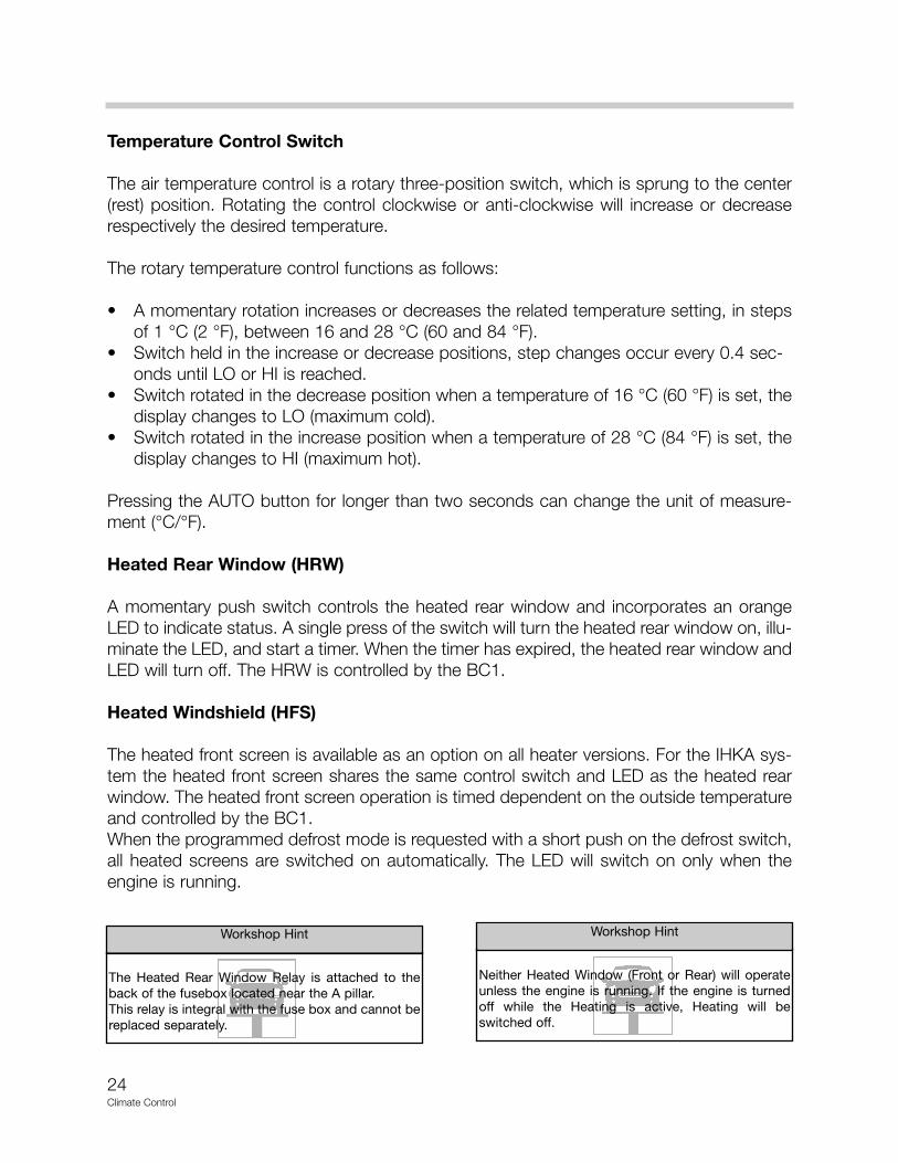
Temperature Control Switch
The air temperature control is a rotary three-position switch, which is sprung to the center(rest) position. Rotating the control clockwise or anti-clockwise will increase or decreaserespectively the desired temperature.
The rotary temperature control functions as follows:
• A momentary rotation increases or decreases the related temperature setting, in stepsof 1 °C (2 °F), between 16 and 28 °C (60 and 84 °F).
• Switch held in the increase or decrease positions, step changes occur every 0.4 sec-onds until LO or HI is reached.
• Switch rotated in the decrease position when a temperature of 16 °C (60 °F) is set, thedisplay changes to LO (maximum cold).
• Switch rotated in the increase position when a temperature of 28 °C (84 °F) is set, thedisplay changes to HI (maximum hot).
Pressing the AUTO button for longer than two seconds can change the unit of measure-ment (°C/°F).
Heated Rear Window (HRW)
A momentary push switch controls the heated rear window and incorporates an orangeLED to indicate status. A single press of the switch will turn the heated rear window on, illu-minate the LED, and start a timer. When the timer has expired, the heated rear window andLED will turn off. The HRW is controlled by the BC1.
Heated Windshield (HFS)
The heated front screen is available as an option on all heater versions. For the IHKA sys-tem the heated front screen shares the same control switch and LED as the heated rearwindow. The heated front screen operation is timed dependent on the outside temperatureand controlled by the BC1.When the programmed defrost mode is requested with a short push on the defrost switch,all heated screens are switched on automatically. The LED will switch on only when theengine is running.
The Heated Rear Window Relay is attached to theback of the fusebox located near the A pillar.This relay is integral with the fuse box and cannot bereplaced separately.
Workshop Hint
Neither Heated Window (Front or Rear) will operateunless the engine is running. If the engine is turnedoff while the Heating is active, Heating will beswitched off.
Workshop Hint

25Climate Control
Fresh Air/Recirculation Switch
The fresh/recirculation air control is a momentary push switch with a green LED to indicatestatus. A single press of the switch will close the fresh air intake and illuminate the recircu-lation LED. Another press of the switch while the LED is illuminated will open the fresh airintake and extinguish the LED.Air recirculation will be controlled automatically if AUTO is selected. This may be overriddenby pressing the air recirculation control. Recirculated air will then remain manually controlleduntil the air recirculation control is pressed again.
AC Switch
Provides manual on/off control of the refrigerant system compressor. The AC can beswitched off to reduce fuel consumption when there is no requirement for cool or dehu-midified air. The AC control is a momentary push switch with a green LED to indicate sta-tus. A single press of the switch will provide the AC function and illuminate the LED; anoth-er press of the switch will switch off the AC function and extinguish the LED. Air condi-tioning compressor is automatically switched on when the AUTO switch is pressed.
Auto/Off Switch
The automatic mode is activated with a single press of the AUTO switch; the green LEDilluminating indicates this to the driver. The air distribution and blower speed is controlledautomatically, and the air conditioning is switched on when AUTO is active.The driver can over-ride the automatic mode of the air distribution or blower by pressingone of the distribution buttons or manually adjusting the blower speed. When the blower isbeing controlled in AUTO mode the blower speed bars and fan symbol are not displayed inthe central display panel. In the automatic mode, if the temperature is set to LO or HI, theblower runs at maximum speed with correction only for vehicle speed.The IHKA control panel may also be switched off by using the OFF horizontal rocker switch.This will switch off the blower and air conditioning, distribution control functions and tem-perature control will also be switched off.
Solar Sensor
The solar sensor consists of a light sensitive diode that provides the IHKA module withinputs of sunlight intensity. The input is used as a measure of the solar heating effect onvehicle occupants. The sensor is installed in the center of the upper dash.
Heater Core Temperature Sensor
The heater core temperature sensor is an encapsulated thermistor that provides the IHKAmodule with air temperature of the heater core. The sensor is installed in the right hand sideheater housing.
26Climate Control
IHKA Control System Principle of Operation
IHKA Controls
On the IHKA system all functions have automatic and some manual modes of operation.The automatic modes provide optimum control of the system and require no manual inter-vention. The manual modes allow individual functions of automatic operation to be overrid-den, to accommodate personal preferences.
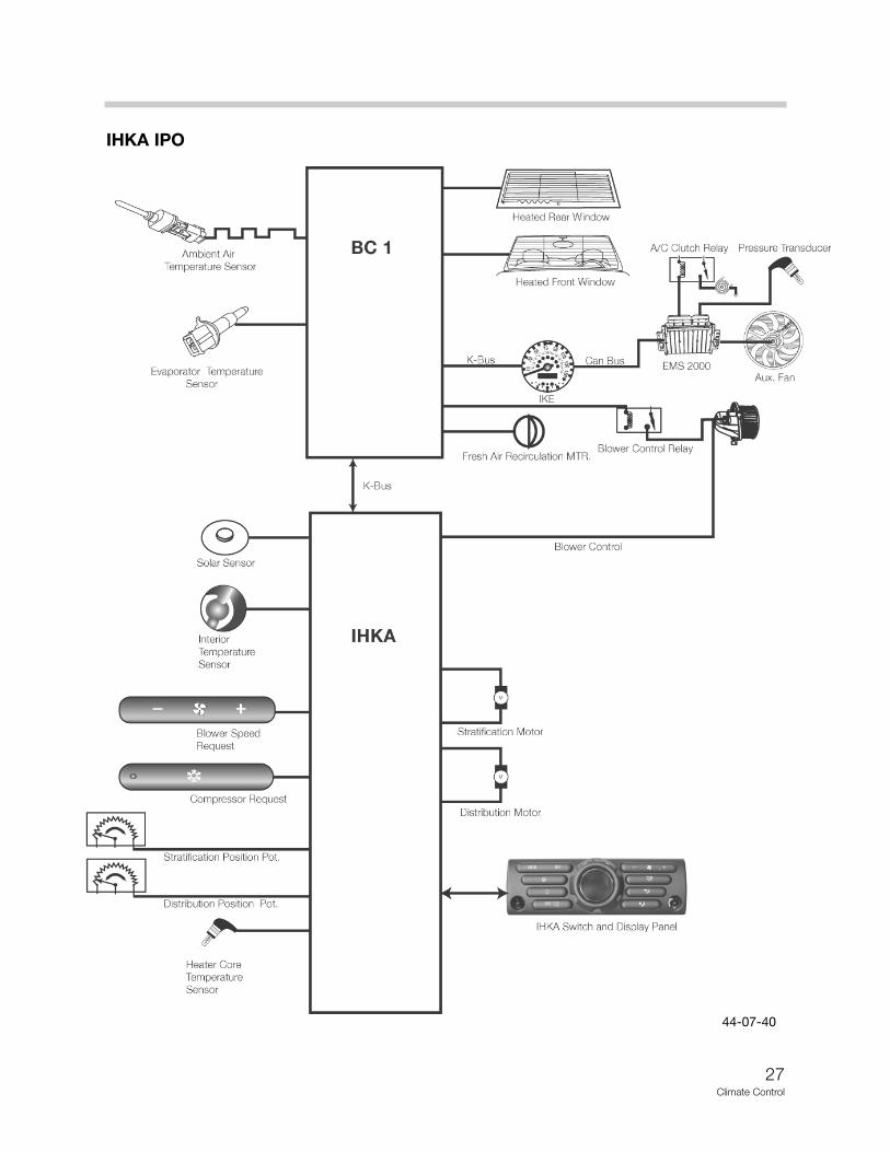
The IHKA control system controls the operation of the refrigerant system and the controlflaps in the heater assembly to control the temperature and distribution of air in the vehicleinterior. It also outputs signals to the BC1 to control the fresh/recirculation air servomotorand to the blower to control the air volume.
Temperature Control
The IHKA receives a temperature input from the Temperature Control Switch. Inputs fromthe Ambient Air Temp Sensor, Evaporator Temp Sensor, Interior Temp Sensor and HeaterCore Air Temp Sensor are evaluated and a Target Temperature is set. The TargetTemperature is the required temperature of the outlet air to achieve the requested temper-ature.
The IHKA module then signals the servomotor controlling the blend flap in the heaterassembly to move the flap to the appropriate position. Feedback information is receivedby the IHKA from the blend flap servo motor to indicate flap position and confirm flap move-ment.
The target temperature is constantly updated and, in the automatic mode, also used in fur-ther calculations to determine the blower speed and the air distribution.
Blower Control
IHKA equipped vehicles have a blower final output stage in place of the resistor pack. Theoutput stage is iinnssttaalllleedd iinn tthhee bblloowweerr aasssseemmbbllyy.In AUTO mode, the blower is automatically regulated. In the manual mode, 8 blower speedsare available. These correspond to approximately 20, 30, 40, 50, 60, 75, 90 and 100% ofbattery voltage.The blower relay is energized by the BC1 whenever the ignition switch is in position 1 or 2,and the IHKA module modulates the output stage to regulate the voltage across the blow-er motor to control blower speed.In the automatic blower and fresh air mode, the blower speed is corrected for vehicle speedto compensate for the increase in ram effect on the inlet air as the vehicle speed increas-es.
Up
dat
ed
Info
rmat
ion
27Climate Control
IHKA IPO
44-07-40

28Climate Control
In the automatic mode, if the temperature is set to LO or HI, the blower runs at maximumspeed with correction only for vehicle speed. When the temperature is set to a specifictemperature, blower speed corrections are added to compensate for the heater coolanttemperature, external air temperature, and the solar load on the vehicle:
• During warm-up, to avoid blowing excessive amounts of cold air into the passenger compartment, the blower speed is limited if the heater core air temperature is below approximately 60 °C. A similar limitation is applied when the exterior temperature falls below -10 °C.
• During cool down, to purge the ducting of hot air, blower speed is limited for a period of approximately 5 seconds after the system is switched on. The blower speed is thenprogressively increased over a period of approximately 10 seconds.
• As the temperature in the passenger compartment approaches the selected tempera-ture, blower speed is progressively reduced until, once the selected temperature hasbeen established, blower speed stabilizes.
• Solar heating correction is employed and progressively increases the blower speed withincreasing values of solar heating.
Air Distribution
In automatic mode, to control air distribution within the passenger compartment, the IHKAmodule signals the servomotor controlling the distribution flap in the heater assembly tomove the flap to the appropriate position. When a specific temperature selection is set, airdistribution is determined from the target air outlet temperatures. For higher target air out-let temperatures, air distribution is set to footwells only. For lower target air outlet temper-atures, air distribution is set to face level only. For intermediate target air outlet tempera-tures, air varies the bias between the footwells and the face level outlets, in three stages,to provide a gradual transition of air distribution from footwells only to face level only.Position and movement confirmation is received from a feedback potentiometer in the airdistribution servo motor.
Fresh/Re-Circulation Air
The IHKA module outputs the required position of the fresh/re-circulated air flap to the BC1,which then operates the servo accordingly.Air re-circulation will be controlled automatically if AUTO is selected. This may be overrid-den by pressing the air re-circulation control. Re-circulated air will then remain manuallycontrolled until the air re-circulation control is pressed again.Fresh or recirculated air is controlled by a flap, driven by a servomotor controlled by theBC1. The IHKA requests the position of the servomotor and flap by sending a K-Bus mes-sage indicating either fresh or recirculated air. The Body Control Module (BC1) respondswith a K-Bus message that is used to switch the LED on/off. The fresh/recirculation ser-vomotor is driven end to end, and then switched-off on a timer. No servo position feed-back is available.

29Climate Control
Programmed Defrost Function
The programmed defrost function is activated by a momentary push of the defrost switch.This function is only available when the engine is running,0.5 seconds after cranking is completed. The programmed defrost functions as follows:
• AUTO mode off.• AC stays ON if ON before or OFF if OFF before.• Fresh/recirculation function is set to fresh air mode.• Desired temperature will be under manual control.• Air distribution will be set to DEFROST vents.• Blower speed 8 selected (depending on battery level).• Heated rear window and (heated front screen if fitted) is requested on.
The display will show the fan speed at MAX (8 bars), and the desired temperature.Thedefrost LED will flash at 0.5 Hz to indicate programmed defrost function is active. The pro-grammed defrost function is not automatically recalled after ignition off.
The programmed defrost function is de-activated by the following actions:
• Brief press of the screen distribution switch will cancel the programmed defrost funct-ion. The control panel will return to its state prior to selection of programmed defrost.
• Foot or face air distribution mode switches will provide manual air mode operation withall other settings returning to their state prior to selection of programmed defrost and cancel the programmed defrost mode.
• A press of the AUTO switch will restore auto operation of the panel and cancels pro-grammed defrost mode.
• A press of the OFF button will switch the panel off. A subsequent press of the OFF button will switch on the panel and restore the programmed defrost function.
• A long push (>2 second) of the defrost switch will provide manual screen distribution and cancel programmed defrost mode.
Heated Front and Rear Windows (HFS/HRW)Operation of the Heated Front and Rear Windows is the same in the IHKA system as in theIHKS system.
Compressor ControlThe control of the compressor is the same as that of the IHKS with the exception of theIHKA module signals compressor request to the EMS2000 via the K-bus and not the BC1.The evaporator sensor still signals to the BC1 as on the IHKS.

30Climate Control
Compressor Cut-out CriteriaFor both versions of air conditioning the following conditions will suspend the operation ofthe compressor:
• Full-load acceleration• Engine coolant temperature > 118 °C• Engine speed > 6016 rpm• Engine speed < 500 rpm• Evaporator temperature < 2 °C• Refrigerant pressure < 1.6 bar / > 30 bar
Notes:
IIHHKKAA CCoommpprreessssoorr CCoonnttrrooll
44-07-26

31Climate Control
IHKA On Board Diagnosis
The on board diagnostics function is a special feature of the IHKA that provides three testmodes:• Mode 1 - Read fault memory• Mode 2 - Calibration run• Mode 3 - Manual check of functions
To access the on board diagnosis function the OFF button and the blower PLUS switchmust be pressed simultaneously for approximately two seconds with the ignition in position2. The central display panel will show a single "streamer bar" to represent mode 1 - Readfault memory. To access mode 1 the AUTO button must be pressed.
To select mode 2 or 3 it is necessary to press the OFF button, the second or third stream-er bar illuminating will indicate the relevant mode to the Technician depending on how manytimes the OFF button is pressed. To access the mode the AUTO button must be pressed.To exit the on board diagnosis mode the ignition must be switched to the off position.
Mode 1: Read Fault MemoryThe IHKA fault memory is read and displayed in the central display panel. If no faults arepresent 00 is displayed and if a fault is stored FF followed by a code number is displayed.This display flashes at 0.5 Hz.
Mode 2: Calibration RunThe objective of the calibration procedure isto correct the position drift of the servomo-tors for temperature and air distribution con-trol. During a calibration run:• Both servomotors are driven to their two
end positions and the new values stored in the IHKA EEPROM.
• All LED’s activated simultaneously.• Blower streamer bars individually illumi-
nated.• CA flashes in the central display panel at
0.5 Hz.There are three possible operating statuses shown in the central display:• CA = Calibration Active •CC = Calibration Complete •FF = Fault
Mode 3: Manual ModeIn this mode blower, air distribution, recirculation, heated screens, air conditioning ON/OFFand temperature are manually controlled.If the engine is running, and the blower is operational, the air conditioning will be controlledmanually by the AC switch. The AUTO, OFF or programmed defrost functions will not beallowed in this mode.
Code Description
01 Solar sensor fault02 Interior temperature sensor fault03 Heater core temperature sensor fault04 Air distribution servomotor feedback fault05 Blend flap servomotor feedback fault06 Blower switch minus fault07 Blower switch plus fault08 Interior sensor fan fault09 Air distribution servomotor fault10 Blend flap servomotor fault
IHKA Fault Codes

32Climate Control
Review Questions
1. Which Climate Control System is Standard on MINI COOPER S ?
2. What are the three sub systems which make up the climate control system?
3. What is the charge capacity of the refrigerant system?
4. What is the location of the Receiver/Drier assembly?
5. The purpose of the expansion valve is to
6. Why is the IHKS Blower Resistor pack installed in an air outlet from the blower?
7. What controls the Fresh/Recirculation flap on an IHKS system?
8. What are the differences in the air distribution control between the IHKS and IHKA?
9. How is the HFS activated on a vehicle with IHKA?
10. As the refrigerant changes from a high pressure liquid to a low pressure gas what events are occurring?
11. What determines the flow rate of refrigerant through the compressor?
12. Explain the blower speed control functions of the resistor pack?
13. What is the primary requirement for HFS/HRW operation?
14. How does the compressor control differ in an IHKS and IHKA system?