mini-cooling-tower
50
-
Upload
kani-vel -
Category
Presentations & Public Speaking
-
view
161 -
download
0
Transcript of mini-cooling-tower


CONTENTS
CHAPTER NO
TITLE
SYNOPSIS
LIST OF FIGURES
NOMENCLATURE
1 Introduction
2 Literature review
3 Description of equipments
3.1 Solar panel components
4 Design and drawing
4.1 components and Specification
4.2 Design calculation
5 fabrication
6 Working principle
7 Merits and demerits
8 applications
9 List of materials
10 Cost Estimation
11 Conclusion
Bibliography
photography

NOMENCLATURE

NOMENCLATURE
A =Area of solar panel(m2 )
D=Diameter of motor shaft (m)
F =Force exerted on the pump (N)
p=Pressure (N/m2)
P=power (W)
I =current (A)
V=voltage (volts)
N =speed ( rpm)

SYNOSPSIS
SYNOPSIS:
This project is the process of removing heat from substance under controlled
conditions. In a reversed system which pumps heat from a cold body and delivers it
to a hot body. The system which works on a extraction of heat from a cold body and
deliver it to a hot body is called cooling tower.

INTRODUCTION

INTRODUCTION
Cooling towers are a very important part of many chemical plants. The primary
task of a cooling tower is to reject heat into the atmosphere. They represent a
relatively inexpensive and dependable means of removing low-grade heat from
cooling water. The make-up water source is used to replenish water lost to
evaporation. Hot water from heat exchangers is sent to the cooling tower. The water
exits the cooling tower and is sent back to the exchangers or to other units for further
cooling. Typical closed loop cooling tower system.

LITERATURE SURVEY

LITERATURE SURVEY
COOLING TOWER TYPES
Cooling towers fall into two main categories: Natural draft and Mechanical
draft. Natural draft towers use very large concrete chimneys to introduce air through
the media. Due to the large size of these towers, they are generally used for water
flow rates above 45,000 m3/hr. These types of towers are used only by utility power
stations.
Mechanical draft towers utilize large fans to force or suck air through
circulated water. The water falls downward over till surfaces, which help increase the
contact time between the water and the air - this helps maximise heat transfer
between the two. Cooling rates of Mechanical draft towers depend upon their fan
diameter and speed of operation. Since, the mechanical draft cooling towers are
much more widely used,
MECHANICAL DRAFT TOWERS
Mechanical draft towers are available in the following airflow arrangements:
I. Counter flows induced draft.
2. Counter flow forced draft.
3. Cross flow induced draft.
In the counter flow induced draft design, hot water enters at the top, while
the air is introduced at the bottom and exits at the top. Both forced and induced draft
fans are used. In cross flow induced draft towers, the water enters at the top and
passes over the fill. The air, however, is introduced at the side either on one side
(single-flow tower) or opposite sides (double-flow tower). An induced draft fan draws

the air across the wetted fill and expels it through the top of the structure. The Figure
7.2 illustrates various cooling tower types. Mechanical draft towers arc available in a
large range of capacities. Normal capacities range from approximately 10 tons, 2.5
m3/hr flow to several thousand tons and m /hr. Towers can be either factory built or
field erected — for example concrete towers arc only field erected.
Many towers arc constructed so that they can be grouped together to
achieve the desired capacity. Thus, many cooling towers are assemblies of two or
more individual cooling towers or cells.‖ The number of cells they have, e.g., a eight-
cell tower, often refers to such towers. Multiple-cell towers can be lineal, square, or
round depending upon the shape of the individual cells and whether the air inlets are
located on the sides or bottoms of the cells.
COMPONENTS OF COOLING TOWER
The basic components of an evaporative tower arc: Frame and casing, fill,
cold water basin, drift eliminators, air inlet, louvers, nozzles and fans.
FRAME AND CASING:
Most towers have structural frames that support the exterior enclosures
(casings), motors, fans, and other components. With some smaller designs, such as
some glass fiber units, the casing may essentially he the frame. Fill: Most towers
employ fills (made of plastic or wood) to facilitate heat transfer by maximising water
and air contact. Fill can either be splash or film type. With splash till, waterfalls over
successive layers of horizontal splash bars, continuously breaking into smaller
droplets, while also wetting the till surface. Plastic splash till promotes better heat
transfer than the wood splash fill. Film fill consists of thin, closely spaced plastic
surfaces over which the water spreads, forming a thin film in contact with the air.
COLD WATER BASIN:
The cold water basin, located at or near the bottom of the tower, receives the
cooled water that flows down through the tower and fill. The basin usually has a
sump or low point for the cold water discharge connection. En many tower designs,
the cold water basin is beneath the entire till. In some forced draft counter flow
design, however, the water at the bottom of the till is channelled to a perimeter
trough that functions as the cold water basin. Propeller fans are mounted beneath
the fill to blow the air up through the tower. With this design, the tower is mounted on
legs, providing easy access to the fans and their motors.
DRIFT ELIMINATORS:
These capture water droplets entrapped in the air stream that otherwise would
be lost to the atmosphere. Air inlet: This is the point of entry for the air entering a
tower. The inlet may take up an entire side of a tower—cross flow design— or be
located low on the side or the bottom of counter flow designs. Louvers: Generally,
cross-flow towers have inlet louvers. The purpose of louvers is to equalize air flow
into the fill and retain the water within the tower. Many counter flow tower designs do
not require louvers.
NOZZLES:
These provide the water sprays to wet the fill. Uniform water distribution at the
top of the fill is essential to achieve proper wetting of the entire fill surface. Nozzles
can either be fixed in place and have either round or square spray patterns or can be
tart of a rotating assembly as found in some circular cross-section towers.

FANS:
Both axial (propeller type) and centrifugal fans arc used in towers. Generally,
propeller fins are used in induced draft towers and both propeller and centrifugal
fans arc found in forced draft towers. Depending upon their size. piopeller fans can
either be fixed or variable pitch. A fan having non-automatic adjustable pitch blades
permits the same fan to be used over a wide range of kW with the fan adjusted to
deliver the desired air flow at the lowest power consumption.
Automatic variable pitch blades can vary air flow in response to changing load
conditions. Tower Materials In the early days of cooling tower manufacture, towers
were constructed primarily of wood. Wooden components included the frame,
casing, louvers, fill, and often the cold water basin. If the basin was not of wood, it
likely was of concrete. Today, tower manufacturers fabricate towers and tower
components from a variety of materials. Often several materials are used to enhance
corrosion resistance, reduce maintenance, and promote reliability and long service
life. Galvanized steel, various grades of stainless steel, glass fiber, and concrete are
widely used in tower construction as well as aluminum and various types of plastics
for some components. Wood towers are still available, but they have glass fiber
rather than wood panels (casing) over the wood framework.
The inlet air louvers may be glass fiber, the fill may be plastic, and the cold
water basin may be steel. Larger towers sometimes are made of concrete. Many
towers—casings and basins— are constructed of galvanized steel or, where a
corrosive atmosphere is a problem, stainless steel. Sometimes a galvanized tower
has a stainlcss stccl basin. Glass fiber is also widely used for cooling tower casings
and basins, giving long life and protection from the harmful effects of many
chemicals.

Heal Load
The heat load imposed on a cooling tower is determined by the process being
served. The degree of cooling required is controlled by the desired operating
temperature level of the process. In most cases, a low operating temperature is
desirable to increase process efficiency or to improve the quality or quantity of the
product. In some applications (e.g. internal combustion engines), however, high
operating temperatures arc desirable. The size and cost of the cooling tower is
proportional to the heat load. If heat load calculations are low undersized equipment
will be purchased.
If the calculated load is high, oversize and more costly, equipment will result.
Process heat loads may vary considerably depending upon the process involved,
Determination of accurate process heat loads can become very complex but proper
consideration can produce satisfactory results. On the other hand, air conditioning
and refrigeration heat loads can be determined with greater accuracy.
Information is available for the heat rejection requirements of various types of power
equipment.
FACTORS
WET BULB TEMPERATURE
Wet bulb temperature is an important factor in perfonnancc of evaporative
water cooling equipment. It is a controlling factor from the aspect of minimum cold
water temperature to which water can be cooled by the evaporative method. Thus,
the wet bulb temperature of the air entering the cooling tower determines operating
temperature levels throughout the plant, process, or system. T

Theoretically, a cooling tower will cool water to the entering wet bulb
temperature, when operating without a heat load. However, a thermal potential is
required to reject heat, so it is not possible to cool water to the entering air wet bulb
temperature, when a heat load is applied. The approach obtained is a function of
thermal conditions and tower capability.
Initial selection of towers with respect to design wet bulb temperature must be
made on the basis of conditions existing at the tower site. The temperature selected
is generally close to the average maximum wet bulb for the sununer months. An
important aspect of wet bulb selection is, whether it is specified as ambient or inlet.
The ambient wet bulb is the temperature, which exists generally in the cooling tower
area, whereas inlet wet bulb is the wet bulb temperature of the air entering the
tower.
The later can be. and often is, affected by discharge vapours being re
circulated into the tower. Recirculation raises the effective wet bulb temperature of
the air entering the tower with corresponding increase in the cold water temperature.
Since there is no initial knowledge or control over the recirculation factor, the
ambient wet bulb should be specified. The cooling tower supplier is required to
furnish a tower of sufficient capability to absorb the effects of the increased wet bulb
temperature peculiar to his own equipment.
It is very important to have the cold water temperature low enough to
exchange heat or to condense vapours at the optimum temperature level. By
evaluating the cost and size of heat exchangers versus the cost anti size of the
cooling tower, the quantity and temperature of the cooling tower water can be
selected to get the maximum economy for the particular process.
EFFICIENT SYSTEM OPERATION
COOLING WATER TREATMENT
Cooling water treatment is mandatory for any cooling tower whether with
splash fill or with film type fill for controlling suspended solids, algac growth, etc.
With increasing costs of water, efforts to increase Cycles of Concentration (COC), by
Cooling Water Treatment would help to reduce make up water requirements
significantly. In large industries, power plants, COC improvement is often considered
as a key area for water conservation.
COOLING TOWER FANS
The purpose of a cooling tower fan is to move a specified quantity of air
through the system, overcoming the system resistance which is defined as the
pressure loss. The product of air flow and the pressure loss is air power
dcvclopcdlwork done by the fan; this may be also termed as fan output and input kW
depends on fan efficiency. The fin efficiency in turn is greatly dependent Ofl the
profile of the blade. An aerodynamic profile with optimum twist, taper and higher
coefficient of lift to coefficient of drop ratio can provide the fan total efficiency as high
as 85-92 %. However, this efficiency is drastically affected by the factors such as tip
clearance, obstacles to airflow and inlet shape, etc.
As the metallic fans are manufactured by adopting either extrusion or casting
process it is always difficult to generate the ideal aerodynamic profiles. The FRP
blades are normally hand moulded which facilitates the generation of optimum
aerodynamic profile to meet specific duty condition more efficiently. Cases reported

where replacement of metallic or Glass fibre reinforced plastic fan blades have been
replaced by efficient hollow FRP blades, with resultant fan energy savings of the
order of 20-30% and with simple pay back period of 6 to 7 months. Also, due to
lightweight, FRP fans need low starting torque resulting in use of lower HP motors.
The lightweight of the fans also increases the life of the gear box, motor and bearing
is and allows for easy handling and maintenance.

DESCRIPTION OF EQUIPMENT

DESCRIPTION OF EQUIPMENT
COMPONENTS
Fan
Dc pump
Sump
tank
FAN
A stand alone fan is typically powered with an electric motor. Fans are often
attached directly to the motor's output, with no need for gears or belts. Smaller fans
are often powered by shaded pole AC motors or brushed or brushless DC motors. In
our case it is powered by dc motor having three blades.
DC CENTRIFUGAL PUMP:
Centrifugal pump is a rotodynamic pump that uses a rotating impeller to
increase the velocity of a fluid. Centrifugal pumps are commonly used to move
liquids through a piping system. The fluid enters the pump impeller along or near to
the rotating axis and is accelerated by the impeller, flowing radially outward into a
diffuser or volute chamber, from where it exits into the downstream piping system.
Centrifugal pumps are used for large discharge through smaller heads
The pump is made of molded plastic. The flow rate of the pump is 1 liter / min
and it can deliver the water up to a head of 3 meters.

The centrifugal pump acts as a reversed of an inward radial flow reaction
turbine. This means that the flow in centrifugal pumps is in the radial outward
directions the centrifugal pump works on the principle of forced vortex flow which
means that when a certain mass of liquid is rotated by an external torque, the rise in
pressure head of the rotating liquid is proportional to the square of tangential velocity
of the liquid at that point. Rise in pressure head).thus at the outlet of the impeller,
where radius is more, the rise in pressure head will be more and the liquid will be
discharged at the outlet with a high pressure head. Due to this high pressure head,
the liquid can be lifted to a high level.
Main parts of a centrifugal pump
Impeller
Casing
Suction pipe with a foot valve and a strainer
Delivery pipe
All the main parts of the centrifugal pump.
(1) IMPELLER:
The rotating part of a centrifugal pump is called ―impeller‖. it consists of a
series of backward curved vanes.the impeller is mounted on a shaft which is
connected to the shaft of an electric motor.
(2) CASING:
The casing of centrifugal pump is similar to the casing of reaction turbine. it is
an air tight passage surrounding the impeller and is designed in such a way that the
kinetic energy of the water discharged at the outlet of the impeller is converted into
pressure energy before the designed in such a way that the kinetic energy of the
water discharged at the outlet of the impeller is converted into pressure energy

before the water leaves the casing and enters the delivery pipe. Suction pipe with a
pipe whose one end is connected to inlet and then other to tank.
(3)SUCTION PIPE FOOT VALVE:
Delivery valve to flow control valve open only in upward direction.A
strains is filled at lower end of the sump
P.M.D.C MOTOR:
The permanent magnet direct current motor ( P.M.D.C) is a 12v dc motor. In
any electric motor, operation is based on simple electromagnetism. A current-
carrying conductor generates a magnetic field; when this is then placed in an
external magnetic field, it will experience a force proportional to the current in the
conductor, and to the strength of the external magnetic field.
D.C MOTOR:
The d.c generators and d.c motors have the same general construction.
MOTOR PRINCIPLE:
An electric motor is a machine which converts an electrical energy to
mechanical energy.
All D.C machines have five principal components viz
(i) Field system (II) armature core (iii) armature winding (iv) Commutator (v)
brushes
(ii) Field system:
The function of the field system is to produce Uniform field within which the
armature rotates.it consists of a number of salient poles(of course, even number)
bolted to the inside of circular frame (generally called yoke).the yoke is usually made
of solid cast steel whereas the pole piece are composed of stacked laminations.

Field coils are mounted on the poles and carry the d.c exciting current. The
field coils are connected in such a way that adjacent poles have opposite polarity.
The m.m.f. developed by the coils produces a magnetic flux that passes through the
pole pieces, the air gap, the armature and the frame. Practical d.c machines have air
gaps ranging from 0.5mm to 1.5mm.since armature and field systems are composed
of materials that have permeability, most of the m.m.f.of field coils is required to set
up flux in the air gap. By reducing the length of air gap, we can reduce the size of
field coils (number of turns).
(iii) Armature core:
The armature core is keyed to the machine shaft and rotates between the field
poles. It consists of slotted soft-iron laminations (about 0.4 to 0.6mm thick) that are
stacked to form a cylindrical core. The laminations are individually coated with a thin
insulating film so that they do not come in electrical contact with each other. The
purpose of laminating the core is to reduce the eddy current loss. The laminations
are slotted to accommodate and provide mechanical security to the armature
winding and to give shorter air gap for the flux to cross between the pole face and
the armature ―teeth‖.
(iv) Armature winding:
The slots of the armature core hold conductors that are connected in a
suitable manner.this are known as armature winding. This is the winding in which
―working‖e.m.f. is induced.
The armature conductors are connected inseries-parallel: the conductors
being connected in series so as to increase the voltage and in parallel paths so as to
increase the current. The armature winding of a d.c.machine is a closed –circuit

winding: the conductors being connected in a symmetrical manner forming a closed
loop or series of closed loops.
(v) Commutator;
A commutator is a mechanical rectifier which converts the alternating voltage
generated in the armature winding into direct voltage across the brushes.the
commutator is made of copper segments insulated from each other by mica sheets
and mounted on the shaft of the machine. The armature conductors are soldered to
the commutator segments in a suitable manner to give rise to the armature
winding.depending upon the manner in which the armature conductors are
connected to the commutator segments, there are tow types of armature winding in
a.d.c. machine viz(a) lap winding (b) wave winding.
Great care is taken in building the commutator because any eccentricity will cause
the brushes to bounce, producing unacceptable sparking .the sparks may burn the
brushes and overheat and carbonize the commutator.
(vi) Brushes:
The purpose of brushes is to ensure electrical connections between the
rotating commutator and stationary external load circuit. The brushes are made of
carbon and rest on the commutator,the brush pressure is adjusted by means of
adjustable springs. if the brush pressure is
Very large, the friction produces heating of the commutator and the
bruches.on the other hand, if it is too weak, the imperfect contact with the
commutator may produce sparking.

STATOR:
The stator is the stationary part of an electric generator or electric motor. The
non-stationary part on an electric motor is the rotor.
Depending on the configuration of a spinning electromotive device the stator
may act as the field magnet, interacting with the armature to create motion, or it may
act as the armature, receiving its influence from moving field coils on the rotor.
The first DC generators (known as dynamos) and DC motors put the field coils
on the stator, and the power generation or motive reaction coils are on the rotor.
This was necessary because a continuously moving power switch known as the
commutator is needed to keep the field correctly aligned across the spinning rotor.
The commutator must become larger and more robust as the current increases.
The stator of these devices may be either a permanent magnet or an
electromagnet. Where the stator is an electromagnet, the coil which energizes it is
known as the field coil or field winding.
ROTOR:
The rotor is the non-stationary part of a rotary electric motor or alternator,
which rotates because the wires and magnetic field of the motor are arranged so
that a torque is developed about the rotor's axis. In some designs, the rotor can act
to serve as the motor's armature, across which the input voltage is supplied.
ELECTROMAGNETIC COIL:
An electromagnetic coil is formed when a conductor solid copper wire is
wound around a core or form to create an inductor or electromagnet. One loop of
wire is usually referred to as a turn, and a coil consists of one or more turns. For use
in an electronic circuit, electrical connection terminals called taps are often

connected to a coil. Coils are often coated with varnish and/or wrapped with
insulating tape to provide additional insulation and secure them in place. A
completed coil assembly with taps etc. is often called a winding. A transformer is an
electromagnetic device that has a primary winding and a secondary winding that
transfer’s energy from one electrical circuit to another by magnetic coupling without
moving parts. The term tickler coil usually refers to a third coil placed in relation to a
primary coil and secondary coil.
A coil tap is a wiring feature found on some electrical transformers, inductors
and coil pickups, all of which are sets of wire coils. The coil tap are points in a wire
coil where a conductive patch has been exposed. As self induction is larger for
larger coil diameter the current in a thick wire tries to flow on the inside. The ideal
use of copper is achieved by foils. Sometimes this means that a spiral is a better
alternative. Multilayer coils have the problem of interlayer capacitance, so when
multiple layers are needed the shape needs to be radically changed to a short coil
with many layers so that the voltage between consecutive layers is smaller.


DESIGN OF EQUIPMENT AND DRAWING
MACHINE COMPONENTS
The SOLAR AIR COLLER consists of the following components to full fill the
requirements of complete operation of the machine.
1. Fan
2. Moto
DESIGN CALCULATION
PUMP CALCULATION:
1. To find out the power required to drive the pump
2. To find the flow rate of pump
a) flow rate
Continuity equation, Q= Area of pump shaft x Velocity
Dia of pump shaft(D) =15mm
Dia of outlet of the pump (d) =3mm
Speed of the pump shaft =3000rpm
Area = π x d2/4
= π x (0 .003)2/4
= 7.06 x 10⁻⁶ m2
Velocity= π x D x n / 60
= π x 0.015 x 3000/60
=2.35 m/s
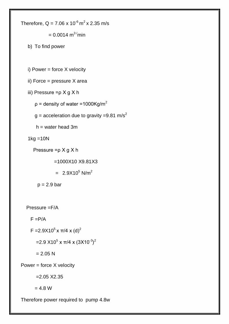
Therefore, Q = 7.06 x 10⁻⁶ m2 x 2.35 m/s
= 0.0014 m3 /min
b) To find power
i) Power = force X velocity
ii) Force = pressure X area
iii) Pressure =ρ X g X h
ρ = density of water =1000Kg/m2
g = acceleration due to gravity =9.81 m/s2
h = water head 3m
1kg =10N
Pressure =ρ X g X h
=1000X10 X9.81X3
= 2.9X10⁵ N/m2
p = 2.9 bar
Pressure =F/A
F =P/A
F =2.9X10⁵ x π/4 x (d)2
=2.9 X10⁵ x π/4 x (3X10-3)2
= 2.05 N
Power = force X velocity
=2.05 X2.35
= 4.8 W
Therefore power required to pump 4.8w

DRAWING


WORKING PRINCIPLE
Hot water flows to the main sewer of the water distribution system. Then, the
water is distributed through a pipe system to spray nozzles. Nozzles cause the
dispersion of the water onto the wet deck surface, thus creating water film of large
contact surface. The water coming off the lower edges of the wet deck surface falls
down in the form of droplets to the cooled water tank, from where it is pumped back
to the cooled equipment.
The process of water cooling occurs mainly as the result of the evaporation of
a small amount of cooled water to the air stream (transport of mass), making the use
of the heat of phase transition (heat of vaporization), which is collected from the
water stream and to a lesser extent as the result of convective heat transfer form
water to air (heat transfer)
Counter-current air flow in the cooling tower is inducted by the suction
produced by the axial fan with a capacity adapted to the required cooling
parameters. The fan is mounted inside the enclosure on the roof of the cooling cell.
The air is sucked into the cell through inlet ports equipped with shutters, which
protect the system from sucking things such as foliage and from splashing cooled
water outside the cooling tower. Then, the sucked air flows through the rain zone
under the wet deck surface, through the fill, splash zone above the wet deck surface
and then it undergoes the process of mist elimination, which minimizes water loss
resulting from dissipation of droplets. The heated and moisten air flows through the
fan, and then it is blown away outside through the upper section of the fan casing to
the environment.

.
MERITS

MERITS
Low cost
High reliable
Low maintenance
Simple in design

APPLICATIONS

APPLICATIONS
Energy savings
Reduce maintenance requirements (personnel and equipment replacement
costs)
Precisely control process water temperature stabilization


LIST OF MATERIALS
FACTORS DETERMINING THE CHOICE OF MATERIALS
The various factors which determine the choice of material are discussed
below.
1. Properties:
The material selected must posses the necessary properties for the proposed
application. The various requirements to be satisfied
Can be weight, surface finish, rigidity, ability to withstand environmental attack
from chemicals, service life, reliability etc.
The following four types of principle properties of materials decisively affect
their selection
a. Physical
b. Mechanical
c. From manufacturing point of view
d. Chemical
The various physical properties concerned are melting point, thermal
Conductivity, specific heat, coefficient of thermal expansion, specific gravity,
electrical conductivity, magnetic purposes etc.
The various Mechanical properties Concerned are strength in tensile,
Compressive shear, bending, torsional and buckling load, fatigue resistance, impact
resistance, eleastic limit, endurance limit, and modulus of elasticity, hardness, wear
resistance and sliding properties.

The various properties concerned from the manufacturing point of view are,
Cast ability
Weld ability
Surface properties
Shrinkage
Deep drawing etc.
2. Manufacturing case:
Sometimes the demand for lowest possible manufacturing cost or surface
qualities obtainable by the application of suitable coating substances may demand
the use of special materials.
3. Quality Required:
This generally affects the manufacturing process and ultimately the material.
For example, it would never be desirable to go casting of a less number of
components which can be fabricated much more economically by welding or hand
forging the steel.
4. Avilability of Material:
Some materials may be scarce or in short supply.it then becomes obligatory
for the designer to use some other material which though may not be a perfect
substitute for the material designed.the delivery of materials and the delivery date of
product should also be kept in mind.
5. Space consideration:
Sometimes high strength materials have to be selected because the forces
involved are high and space limitations are there.

6. Cost:
As in any other problem, in selection of material the cost of material plays an
important part and should not be ignored.
Some times factors like scrap utilization,appearance,and non-maintenance of
the designed part are involved in the selection of proper materials.
S.No DESCIRPTION QTY Material
1 fan 1 Ms
2 Dc pump 1 Moulded
plastic
3 Pipe line 1 plastic

COST ESTIMATION

COST ESTIMATION
1. MATERIAL COST.
S.No DESCRIPTION QTY MATERIAL AMOUNT
(Rs)
1. battery 1 plastic 700
2. fan 1 M.S 1500
3. Dc pump 1 Moulded plastic 1500
4.TOTAL COST:
Total cost = Material Cost +Labour Cost +Overhead Charges
=3700 + 800 + 800
=5300 /-
Total cost for this project (Rs)=5300/-

CONCLUSION

CONCLUSION
This article demonstrates rather pointedly that cooling tower performance and
operation are not so straightforward as they many times are thought to be. These mi
sconceptions and inadequate knowledge of cooling tower design can cost you mone
y in all phases of dealing with cooling towers. Purchase of a new tower will cost mor
e in the long run if plant operations do not run efficiently due to an illdesigned cooling
tower. Tower operation, in terms of energy cost, will be more expensive if utilization
of fan power is misunderstood. Upgrading an existing tower may turn out to be futile
because tower performance was viewed in terms of range. It is necessary to have a
working knowledge of the performance of cooling towers, without misconception, in
order to purchase andoperate them to the best advantage for maximum production a
t minimum cost.


BIBLIOGRAPHY
Strength of Materials -R.S.Kurmi
Manufaturing Technology -M.Haslehurst.
Design of machine elements -R.s.Kurumi