Mini-Circuits Programming Manual
142
Test Solutions - Programming Manual Power Sensors PWR Series Power Sensors PWR Series Peak & Average Power Sensors PO Box 350166, Brooklyn, NY 11235-0003 +1 718-934-4500 | [email protected] www.minicircuits.com
Transcript of Mini-Circuits Programming Manual

Test Solutions - Programming Manual
Power Sensors
PWR Series Power Sensors PWR Series Peak & Average Power Sensors
PO Box 350166, Brooklyn, NY 11235-0003
+1 718-934-4500 | [email protected]
www.minicircuits.com

Important Notice This guide is owned by Mini-Circuits and is protected by copyright, trademark and other intellectual property laws. The information in this guide is provided by Mini-Circuits as an accommodation to our customers and may be used only to promote and accompany the purchase of Mini-Circuits’ Parts. This guide may not be reproduced, modified, distributed, published, stored in an electronic database, or transmitted and the information contained herein may not be exploited in any form or by any means, electronic, mechanical recording or otherwise, without prior written permission from Mini-Circuits. This guide is subject to change, qualifications, variations, adjustments or modifications without notice and may contain errors, omissions, inaccuracies, mistakes or deficiencies. Mini-Circuits assumes no responsibility for, and will have no liability on account of, any of the foregoing. Accordingly, this guide should be used as a guideline only. Trademarks Microsoft, Windows, Visual Basic, Visual C# and Visual C++ are registered trademarks of Microsoft Corporation. LabVIEW and CVI are registered trademarks of National Instruments Corporation. Delphi is a registered trademark of Delphi Technologies, Inc. MATLAB is a registered trademark of The MathWorks, Inc. Agilent VEE is a registered trademark of Agilent Technologies, Inc. Linux is a registered trademark of Linus Torvalds. Mac is a registered trademark of Apple Inc. Python is a registered trademark of Python Software Foundation Corporation. All other trademarks cited within this guide are the property of their respective owners. Neither Mini-Circuits nor the Mini-Circuits PTE (portable test equipment) series are affiliated with or endorsed or sponsored by the owners of the above referenced trademarks. Mini-Circuits and the Mini-Circuits logo are registered trademarks of Scientific Components Corporation. Mini-Circuits 13 Neptune Avenue Brooklyn, NY 11235, USA Phone: +1-718-934-4500 Email: [email protected] Web: www.minicircuits.com
Test Solutions - Programming Manual Page 3 Power Sensors 26-Aug-21 (B3)
1 - Overview ................................................................................................ 6
2 - Operating in a Windows Environment via USB ......................................... 7
2.1 - The DLL (Dynamic Link Library) Concept ....................................................................7 2.1 (a) - ActiveX COM Object ......................................................................................................8 2.1 (b) - Microsoft.NET Class Library ......................................................................................... 10
2.2 - Referencing the DLL Library .....................................................................................11
2.3 - Summary of DLL Properties/Functions .....................................................................12 2.3 (a) - DLL - Properties ........................................................................................................... 12 2.3 (b) - DLL - General Functions ............................................................................................... 12 2.3 (c) - DLL - Average Power Sensor Measurement Functions .................................................. 12 2.3 (d) - DLL - Peak & Average Power Sensor Measurement Functions ...................................... 13 2.3 (e) - DLL - Ethernet Configuration Functions ........................................................................ 13
2.4 - DLL - Properties ........................................................................................................14 2.4 (a) - Set Compensation Frequency ...................................................................................... 14 2.4 (b) - Set Averaging Mode .................................................................................................... 15 2.4 (c) - Set Average Count ....................................................................................................... 16 2.4 (d) - Set Power Format ........................................................................................................ 17 2.4 (e) - Set Offset Value ........................................................................................................... 18 2.4 (f) - Enable Offset ................................................................................................................ 19
2.5 - DLL - General Functions ............................................................................................20 2.5 (a) - Open Power Sensor Connection ................................................................................... 20 2.5 (b) - Close Power Sensor Connection ................................................................................... 21 2.5 (c) - Read Model Name of Power Sensor ............................................................................. 22 2.5 (d) - Read Serial Number of Power Sensor ........................................................................... 23 2.5 (e) - Get List of Connected Serial Numbers .......................................................................... 24 2.5 (f) - Get Status .................................................................................................................... 25 2.5 (g) - Check Connection ........................................................................................................ 26 2.5 (h) - Get Temperature of Power Sensor ............................................................................... 27 2.5 (i) - Get Firmware................................................................................................................ 28 2.5 (j) - Get Firmware Version (Antiquated) .............................................................................. 29 2.5 (k) - Get USB Device Name .................................................................................................. 30 2.5 (l) - Get USB Device Handle ................................................................................................. 31 2.5 (m) - Open Any Power Sensor (Antiquated) ......................................................................... 32 2.5 (n) - Open Any Power Sensor (Antiquated) .......................................................................... 33 2.5 (o) - Close Power Sensor Connection (Antiquated) .............................................................. 34
2.6 - DLL - Average Power Sensor Measurement Functions .............................................35 2.6 (a) - Set Measurement Mode .............................................................................................. 35 2.6 (b) - Set Power Range ......................................................................................................... 36 2.6 (c) - Read Power ................................................................................................................. 37 2.6 (d) - Read Immediate Power ............................................................................................... 38 2.6 (e) - Read Voltage ............................................................................................................... 39 2.6 (f) - Get Offset Values ......................................................................................................... 40 2.6 (g) - Set Offset Values ......................................................................................................... 41
2.7 - DLL - Peak & Average Power Sensor Measurement Functions .................................43 2.7 (a) - Set Sample Time .......................................................................................................... 43 2.7 (b) - Get Sample Time ......................................................................................................... 44 2.7 (c) - Set Trigger Mode ......................................................................................................... 45 2.7 (d) - Get Trigger Mode ........................................................................................................ 46 2.7 (e) - Read Average Power .................................................................................................... 47

Test Solutions - Programming Manual Page 4 Power Sensors 26-Aug-21 (B3)
2.7 (f) - Read Peak Power .......................................................................................................... 48 2.7 (g) - Read Peak & Average Power Array ............................................................................... 49 2.7 (h) - Send SCPI Command .................................................................................................... 50
2.8 - DLL - Ethernet Configuration Functions ....................................................................51 2.8 (a) - Get Ethernet Configuration .......................................................................................... 51 2.8 (b) - Get IP Address ............................................................................................................. 53 2.8 (c) - Get MAC Address ......................................................................................................... 55 2.8 (d) - Get Network Gateway ................................................................................................. 57 2.8 (e) - Get Subnet Mask ......................................................................................................... 59 2.8 (f) - Get TCP/IP Port ............................................................................................................ 61 2.8 (g) - Get DHCP Status .......................................................................................................... 62 2.8 (h) - Get Password Status .................................................................................................... 63 2.8 (i) - Get Password................................................................................................................ 64 2.8 (j) - Save IP Address ............................................................................................................ 65 2.8 (k) - Save Network Gateway ................................................................................................ 66 2.8 (l) - Save Subnet Mask ......................................................................................................... 67 2.8 (m) - Save TCP/IP Port ......................................................................................................... 68 2.8 (n) - Use DHCP .................................................................................................................... 69 2.8 (o) - Use Password .............................................................................................................. 70 2.8 (p) - Set Password ............................................................................................................... 71 2.8 (q) - Get Ethernet Status ..................................................................................................... 72 2.8 (r) - Enable / Disable Ethernet ............................................................................................. 73
3 - Operating in a Linux Environment via USB.............................................. 74
3.1 - Interrupts - General Functions .................................................................................74 3.1 (a) - Get Device Model Name .............................................................................................. 75 3.1 (b) - Get Device Serial Number ............................................................................................ 76 3.1 (c) - Set Measurement Mode .............................................................................................. 77 3.1 (d) - Read Power ................................................................................................................. 78 3.1 (e) - Get Internal Temperature ............................................................................................ 80 3.1 (f) - Get Firmware ............................................................................................................... 81 3.1 (g) - Send SCPI Command .................................................................................................... 82
3.2 - Interrupts - Ethernet Configuration Functions (RC Models Only) .............................83 3.2 (a) - Set Static IP Address .................................................................................................... 84 3.2 (b) - Set Static Subnet Mask ................................................................................................ 85 3.2 (c) - Set Static Network Gateway ......................................................................................... 86 3.2 (d) - Set HTTP Port .............................................................................................................. 87 3.2 (e) - Use Password .............................................................................................................. 88 3.2 (f) - Set Password ................................................................................................................ 89 3.2 (g) - Use DHCP .................................................................................................................... 90 3.2 (h) - Get Static IP Address.................................................................................................... 91 3.2 (i) - Get Static Subnet Mask ................................................................................................. 92 3.2 (j) - Get Static Network Gateway ......................................................................................... 93 3.2 (k) - Get HTTP Port .............................................................................................................. 94 3.2 (l) - Get Password Status ..................................................................................................... 95 3.2 (m) - Get Password ............................................................................................................. 96 3.2 (n) - Get DHCP Status .......................................................................................................... 97 3.2 (o) - Get Dynamic Ethernet Configuration ........................................................................... 98 3.2 (p) - Get MAC Address ...................................................................................................... 100 3.2 (q) - Enable / Disable Ethernet .......................................................................................... 101 3.2 (r) - Reset Ethernet Configuration ..................................................................................... 102

Test Solutions - Programming Manual Page 5 Power Sensors 26-Aug-21 (B3)
4 - Ethernet Control over IP Networks ...................................................... 103
4.1 - Configuring Ethernet Settings via USB ................................................................... 103
4.2 - Ethernet Communication Methodology ................................................................. 104 4.2 (a) - Setting Power Sensor Properties Using HTTP and SCPI ............................................... 104 4.2 (b) - Querying Power Sensor Properties Using HTTP and SCPI ............................................ 105 4.2 (c) - Communication Using Telnet and SCPI ....................................................................... 106
4.3 - Device Discovery Using UDP................................................................................... 107
5 - SCPI Command Summary .................................................................... 109
5.1 - Using SCPI Commands ............................................................................................ 109
5.2 - SCPI - General Functions ........................................................................................ 110 5.2 (a) - Get Model Name ....................................................................................................... 110 5.2 (b) - Get Serial Number ..................................................................................................... 111 5.2 (c) - Get Firmware ............................................................................................................. 112 5.2 (d) - Get Temperature Units .............................................................................................. 113 5.2 (e) - Set Temperature Units ............................................................................................... 114 5.2 (f) - Get Internal Temperature ........................................................................................... 115
5.3 - SCPI - Average Power Sensor Measurement Functions .......................................... 116 5.3 (a) - Get Measurement Mode ........................................................................................... 117 5.3 (b) - Set Measurement Mode ............................................................................................ 118 5.3 (c) - Get Averaging Mode .................................................................................................. 119 5.3 (d) - Set Averaging Mode .................................................................................................. 120 5.3 (e) - Get Average Count .................................................................................................... 121 5.3 (f) - Set Average Count ...................................................................................................... 122 5.3 (g) - Get Compensation Frequency .................................................................................... 123 5.3 (h) - Set Compensation Frequency .................................................................................... 124 5.3 (i) - Read Average Power ................................................................................................... 125 5.3 (j) - Read Voltage .............................................................................................................. 126
5.4 - SCPI - Peak & Average Power Sensor Measurement Functions ............................. 127 5.4 (a) - Get Trigger Mode ...................................................................................................... 128 5.4 (b) - Set Trigger Mode ....................................................................................................... 129 5.4 (c) - Get External Trigger Type ........................................................................................... 130 5.4 (d) - Set External Trigger Type ........................................................................................... 131 5.4 (e) - Get Trigger Delay ....................................................................................................... 132 5.4 (f) - Set Trigger Delay ........................................................................................................ 133 5.4 (g) - Get Trigger Output Mode........................................................................................... 134 5.4 (h) - Set Trigger Output Mode ........................................................................................... 135 5.4 (i) - Get Sample Time ........................................................................................................ 136 5.4 (j) - Set Sample Time ......................................................................................................... 137 5.4 (k) - Get Compensation Frequency .................................................................................... 138 5.4 (l) - Set Compensation Frequency ..................................................................................... 139 5.4 (m) - Read Peak & Average Power ..................................................................................... 140 5.4 (n) - Read Initial Power Array - Ethernet Control Only ....................................................... 141 5.4 (o) - Read Subsequent Power Arrays - Ethernet Control Only ............................................ 142

Test Solutions - Programming Manual Page 6 Power Sensors 26-Aug-21 (B3)
1 - Overview
This Programming Manual is intended for customers wishing to create their own interface for Mini-Circuits' USB and Ethernet controlled power sensors. For instructions on using the supplied GUI program, or connecting the PTE hardware, please see the User Guide at: https://www.minicircuits.com/app/AN48-003.pdf Mini-Circuits offers support over a variety of operating systems, programming environments and third party applications. Support for Windows® operating systems is provided through the Microsoft®.NET® and ActiveX® frameworks to allow the user to develop customized control applications. Support for Linux® operating systems is accomplished using the standard libhid and libusb libraries. Mini-Circuits has experience with a wide variety of environments including (but not limited to):
• Visual Basic®, Visual C#®, Visual C++®
• Delphi®
• Borland C++®
• CVI®
• LabVIEW®
• MATLAB®
• Python®
• Keysight VEE® The power meter software package includes a GUI program, ActiveX and .NET DLL files, Linux support, project examples for third party software, and detailed user manuals. The latest package is available for download at: https://www.minicircuits.com/softwaredownload/pm.html For details on individual models, application notes, GUI installation instructions and user guides please see: https://www.minicircuits.com/WebStore/PortableTestEquipment.html Files made available for download from the Mini-Circuits website are subject to Mini-Circuits’ terms of use which are available on the website.

Test Solutions - Programming Manual Page 7 Power Sensors 26-Aug-21 (B3)
2 - Operating in a Windows Environment via USB When connected by USB, the computer will recognize the power meter as a Human Interface Device (HID). In this mode of operation the DLL file provides the method of control. Alternatively, the “RC” series of power meters can be operated over an Ethernet TCP/IP Network (see Ethernet Control over IP Networks for details).
2.1 - The DLL (Dynamic Link Library) Concept The Dynamic Link Library concept is Microsoft's implementation of the shared library concept in the Windows environment. DLLs provide a mechanism for shared code and data, intended to allow a developer to distribute applications without requiring code to be re-linked or recompiled. Mini-Circuits' CD package provides DLL Objects designed to allow your own software application to interface with the functions of the Mini-Circuits power meter.
The software package provides two DLL files, the choice of which file to use is dictated by the user’s operating system:
1. ActiveX com object
Designed to be used in any programming environment that supports third party ActiveX COM (Component Object Model) compliant applications. The ActiveX file should be registered using RegSvr32 (see following sections for details).
2. Microsoft.NET Class Library
A logical unit of functionality that runs under the control of the Microsoft.NET system.
User’s Software Application (3rd party software such as LabVIEW, Delphi, Visual C++,
Visual C#, Visual Basic, and Microsoft.Net)
DLL (Dynamic Link Libraries)
Mini-Circuits’
USB Portable Test Equipment
Fig 2.1-a: DLL Interface Concept

Test Solutions - Programming Manual Page 8 Power Sensors 26-Aug-21 (B3)
2.1 (a) - ActiveX COM Object
ActiveX COM object DLL files are designed to be used with both 32-bit and 64-bit Windows operating systems. A 32-bit programming environment that is compatible with ActiveX is required. To develop 64-bit applications, the Microsoft.NET Class library should be used instead.
Supported Programming Environments
Mini-Circuits’ power meters have been tested in the following programming environments. This is not an exhaustive list and the DLL file is designed to operate in most environments that support ActiveX functionality. Please contact Mini-Circuits for support.
• Visual Studio® 6 (Visual C++ and Visual Basic)
• LabVIEW 8.0 or newer
• MATLAB 7 or newer
• Delphi
• Borland C++
• Agilent VEE
• Python Installation
1. Copy the DLL file to the correct directory: For 32-bit Windows operating systems this is C:\WINDOWS\System32 For 64-bit Windows operating systems this is C:\WINDOWS\SysWOW64
2. Open the Command Prompt: a. For Windows XP® (see Fig 2.1-b):
i. Select “All Programs” and then “Accessories” from the Start Menu ii. Click on “Command Prompt” to open
b. For later versions of the Windows operating system you will need to have Administrator privileges in order to run the Command Prompt in “Elevated” mode (see Fig 2.1-c for Windows 7 and Windows 8):
i. Open the Start Menu/Start Screen and type “Command Prompt” ii. Right-click on the shortcut for the Command Prompt
iii. Select “Run as Administrator” iv. You may be prompted to enter the log in details for an Administrator
account if the current user does not have Administrator privileges on the local PC
3. Use regsvr32 to register the DLL: For 32-bit Windows operating systems type (see Fig 2.1-d):
\WINDOWS\System32\Regsvr32 \WINDOWS\System32\mcl_pm.dll
For 64-bit Windows operating systems type (see Fig 2.1-e): \WINDOWS\SysWOW64\Regsvr32 \WINDOWS\SysWOW64\mcl_pm.dll
4. Hit enter to confirm and a message box will appear to advise of successful registration.

Test Solutions - Programming Manual Page 9 Power Sensors 26-Aug-21 (B3)
Fig 2.1-b: Opening the Command Prompt in Windows XP
Fig 2.1-c: Opening the Command Prompt in Windows 7 (left), Windows 8 (middle) and Windows 10 (right)
Fig 2.1-d: Registering the DLL in a 32-bit environment
Fig 2.1-e: Registering the DLL in a 64-bit environment

Test Solutions - Programming Manual Page 10 Power Sensors 26-Aug-21 (B3)
2.1 (b) - Microsoft.NET Class Library
Microsoft.NET class libraries are designed to be used with both 32-bit and 64-bit Windows operating systems. To develop 64-bit applications the user must have both a 64-bit operating system and 64-bit programming environment. However, the Microsoft.NET class library is also compatible with 32-bit programming environments.
Supported Programming Environments
Mini-Circuits’ power meters have been tested in the following programming environments. This is not an exhaustive list and the DLL file is designed to operate in most environments that support Microsoft.NET functionality. Please contact Mini-Circuits for support.
• National Instruments CVI
• Microsoft.NET (Visual C++, Visual Basic.NET, Visual C# 2003 or newer)
• LabVIEW 2009 or newer
• MATLAB 2008 or newer
• Delphi
• Borland C++ Installation
1. Copy the DLL file to the correct directory a. For 32 bit Windows operating systems this is C:\WINDOWS\System32 b. For 64 bit Windows operating systems this is C:\WINDOWS\SysWOW64
2. No registration is required

Test Solutions - Programming Manual Page 11 Power Sensors 26-Aug-21 (B3)
2.2 - Referencing the DLL Library The DLL file should be installed in the host PC’s system folders using the steps outlined above. Some programming environments will require the user to set a reference to the relevant DLL file, usually through a built in GUI in the programming environment. Once this is done, a new instance of the USB power sensor class just needs to be created for each physical sensor to control. The details of this vary greatly between programming environments and languages but Mini-Circuits can provide detailed support on request. The names "MyPTE1" and "MyPTE2" have been assigned to 2 connected power sensors in the examples below.
Example Declarations using the ActiveX DLL
Example Declarations using the .NET DLL
Visual Basic Public MyPTE1 As New mcl_pm.USB_PM
' Initialize new power sensor object, assign to MyPTE1
Public MyPTE2 As New mcl_pm.USB_PM
' Initialize new power sensor object, assign to MyPTE2
Visual C++ mcl_pm::USB_PM ^MyPTE1 = gcnew mcl_pm::USB_PM();
// Initialize new power sensor instance, assign to MyPTE1
mcl_pm::USB_PM ^MyPTE2 = gcnew mcl_pm::USB_PM();
// Initialize new power sensor instance, assign to MyPTE2 Visual C#
mcl_pm.USB_PM MyPTE1 = new mcl_pm.USB_PM();
// Initialize new power sensor instance, assign to MyPTE1
mcl_pm.USB_PM MyPTE2 = new mcl_pm.USB_PM();
// Initialize new power sensor instance, assign to MyPTE2 Matlab
MyPTE1 = actxserver('mcl_pm.USB_PM')
% Initialize new power sensor instance, assign to MyPTE1
MyPTE2 = actxserver('mcl_pm.USB_PM')
% Initialize new power sensor instance, assign to MyPTE2
Visual Basic Public MyPTE1 As New mcl_pm64.usb_pm
' Initialize new power sensor object, assign to MyPTE1
Public MyPTE2 As New mcl_pm64.usb_pm
' Initialize new power sensor object, assign to MyPTE2
Visual C++ mcl_pm64::usb_pm ^MyPTE1 = gcnew mcl_pm64::usb_pm();
// Initialize new power sensor instance, assign to MyPTE1
mcl_pm64::usb_pm ^MyPTE2 = gcnew mcl_pm64::usb_pm();
// Initialize new power sensor instance, assign to MyPTE2 Visual C#
mcl_pm64.usb_pm MyPTE1 = new mcl_pm64.usb_pm();
// Initialize new power sensor instance, assign to MyPTE1
mcl_pm64.usb_pm MyPTE2 = new mcl_pm64.usb_pm();
// Initialize new power sensor instance, assign to MyPTE2 Matlab
MCL_PM = NET.addAssembly('C:\Windows\SysWOW64\mcl_pm64.dll')
MyPTE1 = mcl_pm64.usb_pm % Initialize new sensor instance
MyPTE2 = mcl_pm64.usb_pm % Initialize new sensor instance

Test Solutions - Programming Manual Page 12 Power Sensors 26-Aug-21 (B3)
2.3 - Summary of DLL Properties/Functions The following functions and “global” properties are defined in both of the DLL files to allow full control over the power sensor. Please see the following sections for a description of their usage.
2.3 (a) - DLL - Properties a) double Freq b) short AVG c) short AvgCount d) bool Format_mw e) single OffsetValue f) short OffsetValue_Enable
2.3 (b) - DLL - General Functions
a) int Open_Sensor(Optional string SN_Request) (ActiveX) short Open_Sensor(Optional string SN_Request) (.NET)
b) void Close_Sensor() c) string GetSensorModelName() d) string GetSensorSN() e) short Get_Available_SN_List(ByRef string SN_List) f) short GetStatus() g) short Check_Connection() h) float GetDeviceTemperature(Optional string
TemperatureFormat) (ActiveX) float GetDeviceTemperature(Optional ByRef string
TemperatureFormat) (.NET) i) short GetFirmwareInfo(ByRef short FirmwareID,
ByRef string FirmwareRev, ByRef short FirmwareNo)
j) short GetFirmwareVer(ByRef short FirmwareVer) k) string GetUSBDeviceName() l) string GetUSBDeviceHandle() m) short Open_AnySensor() n) void Init_PM() o) void CloseConnection()
2.3 (c) - DLL - Average Power Sensor Measurement Functions
These functions apply to the following Mini-Circuits’ power sensor series:
• PWR-xGHS Series (CW average power sensors)
• PWR-xFS Series (fast sampling CW average power sensors)
• PWR-xRMS Series (true RMS power sensors) a) void SetFasterMode(short S_A) (ActiveX)
void SetFasterMode(ByRef short S_A) (.NET) b) void SetRange(short Range) c) float ReadPower() d) float ReadImmediatePower() e) float ReadVoltage() f) short GetOffsetValues(ByRef int NoOfPoints,
ByRef double FreqArray(), ByRef single LossArray())
g) int SetOffsetValues(int NoOfPoints, double FreqArray(),
single LossArray()) (ActiveX) int SetOffsetValues(int NoOfPoints, ByRef double FreqArray(),
ByRef single LossArray()) (.NET)

Test Solutions - Programming Manual Page 13 Power Sensors 26-Aug-21 (B3)
2.3 (d) - DLL - Peak & Average Power Sensor Measurement Functions
These functions apply to Mini-Circuits’ PWR-xP Series peak & average power sensor models. a) short PeakPS_SetSampleTime(long ST) b) long PeakPS_GetSampleTime() c) short PeakPS_SetTriggerMode(int TM) d) short PeakPS_GetTriggerMode() e) float PeakPS_GetAvgPower() f) float PeakPS_GetPeakPower() g) short PeakPS_GetPower(int NoOfPoints, float PowerArray(),
float PeakPower)
h) short Send_SCPI(ByRef string SndSTR, ByRef string RetSTR)
2.3 (e) - DLL - Ethernet Configuration Functions
These functions apply to Mini-Circuits’ RC power sensor models with an Ethernet interface. The functions provide a means for identifying or configuring the Ethernet settings such as IP address, TCP/IP port and network gateway. They can only be called while the device is connected via the USB interface. a) int GetEthernet_CurrentConfig(ByRef int IP1, int IP2,
ByRef int IP3, ByRef int IP4, ByRef int Mask1,
ByRef int Mask2, ByRef int Mask3, ByRef int Mask4,
ByRef int Gateway1, ByRef int Gateway2,
ByRef int Gateway3, ByRef int Gateway4)
b) int GetEthernet_IPAddress(ByRef int b1, ByRef int b2, ByRef int b3, int b4)
c) int GetEthernet_MACAddress(ByRef int MAC1 , ByRef int MAC2, ByRef int MAC3, ByRef int MAC4,
ByRef int MAC5, ByRef int MAC6)
d) int GetEthernet_NetworkGateway(ByRef int b1, ByRef int b2, ByRef int b3, ByRef int b4)
e) int GetEthernet_SubNetMask(ByRef int b1, ByRef int b2, ByRef int b3, ByRef int b4)
f) int GetEthernet_TCPIPPort(ByRef int port) g) int GetEthernet_UseDHCP() h) int GetEthernet_UsePWD() i) int GetEthernet_PWD(ByRef string Pwd) j) int SaveEthernet_IPAddress(int b1, int b2, int b3, int b4) k) int SaveEthernet_NetworkGateway(int b1, int b2, int b3, int b4) l) int SaveEthernet_SubnetMask(int b1, int b2, int b3, int b4) m) int SaveEthernet_TCPIPPort(int port) n) int SaveEthernet_UseDHCP(int UseDHCP) o) int SaveEthernet_UsePWD(int UsePwd) p) int SaveEthernet_PWD(string Pwd) q) int GetEthernet_EnableEthernet() r) int SaveEthernet_EnableEthernet(short Enable)

Test Solutions - Programming Manual Page 14 Power Sensors 26-Aug-21 (B3)
2.4 - DLL - Properties
2.4 (a) - Set Compensation Frequency
Property double Freq
Description
This property sets the power sensor frequency compensation to the correct frequency in MHz for the expected input signal. This parameter needs to be set in order to achieve the specified power measurement accuracy. Note: This property will not filter out unwanted signals.
Accepted Values
Data Type Value Description
double Frequency A frequency within the power sensor’s specified range
Examples
Visual Basic MyPTE1.Freq = 1000
Visual C++ MyPTE1->Freq = 1000;
Visual C# MyPTE1.Freq = 1000;
Matlab MyPTE1.Freq = 1000
Test Solutions - Programming Manual Page 15 Power Sensors 26-Aug-21 (B3)
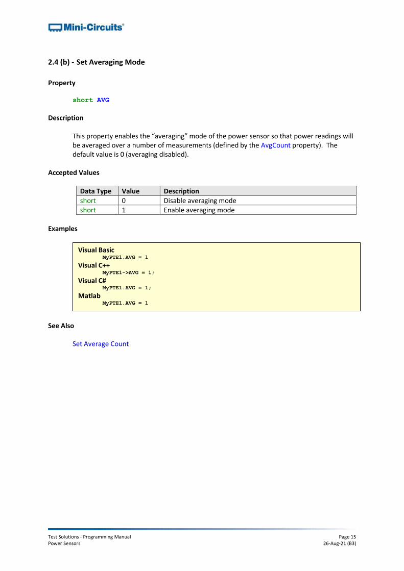
2.4 (b) - Set Averaging Mode
Property short AVG
Description
This property enables the “averaging” mode of the power sensor so that power readings will be averaged over a number of measurements (defined by the AvgCount property). The default value is 0 (averaging disabled).
Accepted Values
Data Type Value Description
short 0 Disable averaging mode
short 1 Enable averaging mode
Examples
See Also
Set Average Count
Visual Basic MyPTE1.AVG = 1
Visual C++ MyPTE1->AVG = 1;
Visual C# MyPTE1.AVG = 1;
Matlab MyPTE1.AVG = 1

Test Solutions - Programming Manual Page 16 Power Sensors 26-Aug-21 (B3)
2.4 (c) - Set Average Count
Property short AvgCount
Description
This property defines the number of power readings over which to average the measurement when averaging mode is enabled (defined by the AVG property). The default value is 1 (average the reading over 1 measurement).
Accepted Values
Data Type Value Description
short Count The number of measurements to average (from 1 to 16)
Examples
See Also
Set Averaging Mode
Visual Basic MyPTE1.AvgCount = 10
Visual C++ MyPTE1->AvgCount = 10;
Visual C# MyPTE1.AvgCount = 10;
Matlab MyPTE1.AvgCount = 10

Test Solutions - Programming Manual Page 17 Power Sensors 26-Aug-21 (B3)
2.4 (d) - Set Power Format
Property bool Format_mw
Description
This property sets the power measurement units to either mW or dBm. The default is power measurements in dBm.
Accepted Values
Data Type Value Description
bool False Power reading in dBm
bool True Power reading in mW
Examples
See Also
Read Power Read Immediate Power
Visual Basic MyPTE1.Format_mw = TRUE
Visual C++ MyPTE1->Format_mw = TRUE;
Visual C# MyPTE1.Format_mw = TRUE;
Matlab MyPTE1.Format_mw = TRUE

Test Solutions - Programming Manual Page 18 Power Sensors 26-Aug-21 (B3)
2.4 (e) - Set Offset Value
Property single OffsetValue
Description
This property sets a single offset value to be used for power readings. The power meter offset type must be set to “1” in order to use this (see OffsetValue_Enable).
Accepted Values
Data Type Value Description
single Offset The power measurement offset in dB
Examples
See Also
Enable Offset
Visual Basic MyPTE1.OffsetValue_Enable = 1
MyPTE1.OffsetValue = 5.4
' Set a 5.4dB offset to the power readings
Visual C++ MyPTE1->OffsetValue_Enable = 1;
MyPTE1->OffsetValue = 5.4;
// Set a 5.4dB offset to the power readings
Visual C# MyPTE1.OffsetValue_Enable = 1;
MyPTE1.OffsetValue = 5.4;
// Set a 5.4dB offset to the power readings
Matlab MyPTE1.OffsetValue_Enable = 1
MyPTE1.OffsetValue = 5.4
% Set a 5.4dB offset to the power readings

Test Solutions - Programming Manual Page 19 Power Sensors 26-Aug-21 (B3)
2.4 (f) - Enable Offset
Property short OffsetValue_Enable
Description
This property defines whether an offset is used for the power readings. The power sensor can use either a single offset value (set using the Set Offset Value property) or an array of offset values (set by the Set Offset Values function).
Accepted Values
Data Type Value Description
short 0 Offset disabled
short 1 Use single value offset (see Set Offset Value)
short 2 Use array of offset values (see Set Offset Values)
Examples
See Also
Set Offset Value Get Offset Values Set Offset Values
Visual Basic MyPTE1.OffsetValue_Enable = 1
MyPTE1.OffsetValue = 5.4
' Set a 5.4dB offset to the power readings
Visual C++ MyPTE1->OffsetValue_Enable = 1;
MyPTE1->OffsetValue = 5.4;
// Set a 5.4dB offset to the power readings
Visual C# MyPTE1.OffsetValue_Enable = 1;
MyPTE1.OffsetValue = 5.4;
// Set a 5.4dB offset to the power readings
Matlab MyPTE1.OffsetValue_Enable = 1
MyPTE1.OffsetValue = 5.4
% Set a 5.4dB offset to the power readings

Test Solutions - Programming Manual Page 20 Power Sensors 26-Aug-21 (B3)
2.5 - DLL - General Functions
2.5 (a) - Open Power Sensor Connection
ActiveX Declaration (mcl_pm.dll) short Open_Sensor(Optional string SN)
.NET Declaration (mcl_pm64.dll) short Open_Sensor(Optional ByRef string SN)
Description
This function is called to initialize the connection to a USB power sensor. If multiple sensors are connected to the same computer, then the serial number should be included, otherwise this can be omitted. The connection process can take a few seconds so it is recommended that the connection be made once at the beginning of the routine and left open until the sensor is no longer needed. The sensor should be disconnected on completion of the program using the Close_Sensor function.
Parameters
Data Type Variable Description
string SN Optional. A string containing the serial number of the USB power sensor. Can be omitted if only one sensor is connected but must be included otherwise.
Return Values
Data Type Value Description
short 0 No connection was possible
1 Connection successfully established
2 Device already connected
3 Requested serial number is not available
Examples
See Also Close Power Sensor Connection
Visual Basic Status = MyPTE1.Open_Sensor("1130902001")
Visual C++ Status = MyPTE1->Open_Sensor("1130902001");
Visual C# Status = MyPTE1.Open_Sensor("1130902001");
Matlab Status = MyPTE1.Open_Sensor("1130902001")

Test Solutions - Programming Manual Page 21 Power Sensors 26-Aug-21 (B3)
2.5 (b) - Close Power Sensor Connection
Declaration void Close_Sensor()
Description
This function is called to close the connection to the power sensor. It is strongly recommended that this function is used prior to ending the program. Failure to do so may result in a connection problem with the device. Should this occur, shut down the program and unplug the power sensor from the computer, then reconnect the power sensor before attempting to start again.
Parameters
Data Type Variable Description
None
Return Values
Data Type Value Description
None
Examples
See Also
Open Power Sensor Connection
Visual Basic MyPTE1.Close_Sensor()
Visual C++ MyPTE1->Close_Sensor();
Visual C# MyPTE1.Close_Sensor();
Matlab MyPTE1.Close_Sensor

Test Solutions - Programming Manual Page 22 Power Sensors 26-Aug-21 (B3)
2.5 (c) - Read Model Name of Power Sensor
Declaration string GetSensorModelName()
Description
This function is called to determine the Mini-Circuits part number of the connected power sensor.
Parameters
Data Type Variable Description
None
Return Values
Data Type Value Description
string Model Mini-Circuits model name of the connected sensor
Examples
See Also Read Serial Number of Power Sensor
Visual Basic MsgBox ("The connected sensor is " & MyPTE1.GetSensorModelName)
Visual C++ MessageBox::Show ("The connected sensor is " + MyPTE1->GetSensorModelName());
Visual C# MessageBox.Show ("The connected sensor is " + MyPTE1.GetSensorModelName());
Matlab ModelName = MyPTE1.GetSensorModelName
h = msgbox('The connected sensor is ', ModelName)
Test Solutions - Programming Manual Page 23 Power Sensors 26-Aug-21 (B3)
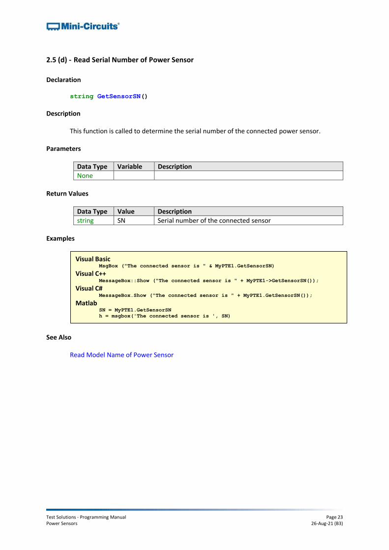
2.5 (d) - Read Serial Number of Power Sensor
Declaration string GetSensorSN()
Description
This function is called to determine the serial number of the connected power sensor. Parameters
Data Type Variable Description
None
Return Values
Data Type Value Description
string SN Serial number of the connected sensor
Examples
See Also
Read Model Name of Power Sensor
Visual Basic MsgBox ("The connected sensor is " & MyPTE1.GetSensorSN)
Visual C++ MessageBox::Show ("The connected sensor is " + MyPTE1->GetSensorSN());
Visual C# MessageBox.Show ("The connected sensor is " + MyPTE1.GetSensorSN());
Matlab SN = MyPTE1.GetSensorSN
h = msgbox('The connected sensor is ', SN)
Test Solutions - Programming Manual Page 24 Power Sensors 26-Aug-21 (B3)
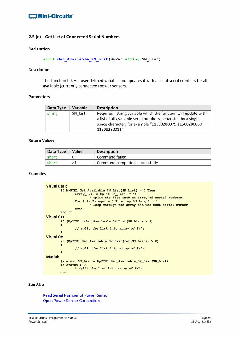
2.5 (e) - Get List of Connected Serial Numbers
Declaration short Get_Available_SN_List(ByRef string SN_List)
Description
This function takes a user defined variable and updates it with a list of serial numbers for all available (currently connected) power sensors.
Parameters
Data Type Variable Description
string SN_List Required. string variable which the function will update with a list of all available serial numbers, separated by a single space character, for example “11508280079 11508280080 11508280081”.
Return Values
Data Type Value Description
short 0 Command failed
short >1 Command completed successfully
Examples
See Also Read Serial Number of Power Sensor Open Power Sensor Connection
Visual Basic If MyPTE1.Get_Available_SN_List(SN_List) > 0 Then
array_SN() = Split(SN_List, " ")
' Split the list into an array of serial numbers
For i As Integer = 0 To array_SN.Length - 1
' Loop through the array and use each serial number
Next
End If Visual C++
if (MyPTE1 ->Get_Available_SN_List(SN_List) > 0)
{
// split the List into array of SN's
} Visual C#
if (MyPTE1.Get_Available_SN_List(ref(SN_List)) > 0)
{
// split the List into array of SN's
} Matlab
[status, SN_List]= MyPTE1.Get_Available_SN_List(SN_List)
if status > 0
% split the List into array of SN's
end

Test Solutions - Programming Manual Page 25 Power Sensors 26-Aug-21 (B3)
2.5 (f) - Get Status
Declaration short GetStatus()
Description
This function checks whether the USB connection to the power sensor is still active. Parameters
Data Type Variable Description
None
Return Values
Data Type Value Description
short 0 No connection
short 1 USB connection to power sensor is active
Examples
See Also Read Power
Visual Basic Status = MyPTE1.Get_Status
Visual C++ Status= MyPTE1->Get_Status();
Visual C# Status= MyPTE1.Get_Status();
Matlab Status= MyPTE1.Get_Status

Test Solutions - Programming Manual Page 26 Power Sensors 26-Aug-21 (B3)
2.5 (g) - Check Connection
Declaration short Check_Connection()
Description
This function checks whether the USB connection to the power sensor is still active. Parameters
Data Type Variable Description
None
Return Values
Data Type Value Description
short 0 No connection
short 1 USB connection to power sensor is active
Examples
See Also Read Power
Visual Basic Status = MyPTE1.Check_Connection
Visual C++ Status= MyPTE1->Check_Connection();
Visual C# Status= MyPTE1.Check_Connection();
Matlab Status= MyPTE1.Check_Connection

Test Solutions - Programming Manual Page 27 Power Sensors 26-Aug-21 (B3)
2.5 (h) - Get Temperature of Power Sensor
ActiveX Declaration (mcl_pm.dll)
float GetDeviceTemperature(Optional string TemperatureFormat)
.NET Declaration (mcl_pm64.dll)
float GetDeviceTemperature(Optional ByRef string TemperatureFormat)
Description
This function returns the internal temperature of the power sensor in degrees Celsius (default) or Fahrenheit.
Parameters
Data Type Variable Description
string Temperature _Format
Optional. string (not case sensitive) to set the temperature measurement units: F - Set temperature units to Fahrenheit C- Set temperature units to Celsius (default)
Return Values
Data Type Value Description
float Temperature The device internal temperature in degrees Celsius
Examples
See Also Read Power Read Immediate Power
Visual Basic MsgBox ("Temperature is " & MyPTE1.GetDeviceTemperature)
Visual C++ MessageBox::Show ("Temperature is " + MyPTE1->GetDeviceTemperature());
Visual C# MessageBox.Show ("Temperature is " + MyPTE1.GetDeviceTemperature());
Matlab h = msgbox ("Temperature is " & MyPTE1.GetDeviceTemperature)

Test Solutions - Programming Manual Page 28 Power Sensors 26-Aug-21 (B3)
2.5 (i) - Get Firmware
Declaration short GetFirmwareInfo(ByRef short FirmwareID,
ByRef string FirmwareRev, ByRef short FirmwareNo)
Description
This function returns a numeric value which indicates the internal firmware version of the power sensor.
Parameters
Data Type Variable Description
short FirmwareID Required. User defined variable for factory use only.
string FirmwareRev Required. User defined variable which will be updated with the current firmware version, for example “B3”.
short FirmwareNo Required. User defined variable for factory use only.
Return Values
Data Type Value Description
short 0 Command failed
short 1 Command completed successfully
Examples
Visual Basic If MyPTE1.GetFirmwareInfo(fID, fRev, fNo) > 0 Then
MsgBox ("Firmware version is " & fRev)
End If Visual C++
if (MyPTE1->GetFirmwareInfo(fID, fRev, fNo) > 0 )
{
MessageBox::Show("Firmware version is " + fRev);
} Visual C#
if (MyPTE1.GetFirmwareInfo(ref(fID, fRev, fNo)) > 0 )
{
MessageBox.Show("Firmware version is " + fRev);
} Matlab
[status, fID, fRev, fNo]=MyPTE1.GetFirmwareInfo(fID, fRev, fNo)
if status > 0
h = msgbox('Firmware version is ', fRev)
end

Test Solutions - Programming Manual Page 29 Power Sensors 26-Aug-21 (B3)
2.5 (j) - Get Firmware Version (Antiquated)
Declaration short GetFirmwareVer(ByRef short FirmwareVer)
Description
This function is antiquated, GetFirmwareInfo should be used instead. GetFirmwareVer returns a numeric value which indicates the internal firmware version of the power sensor.
Parameters
Data Type Variable Description
short FirmwareVer Required. User defined variable which will be updated with the firmware version number
Return Values
Data Type Value Description
short 0 Command failed
short 1 Command completed successfully
Examples
See Also
Get Firmware
Visual Basic status = MyPTE1.GetFirmwareVer(FirmwareVer)
Visual C++ status = MyPTE1->GetFirmwareVer(FirmwareVer);
Visual C# status = MyPTE1.GetFirmwareVer(FirmwareVer);
Matlab status = MyPTE1.GetFirmwareVer(FirmwareVer)

Test Solutions - Programming Manual Page 30 Power Sensors 26-Aug-21 (B3)
2.5 (k) - Get USB Device Name
Declaration string GetUSBDeviceName()
Description
This function is for advanced users to identify the USB device name of the sensor for direct communication.
Parameters
Data Type Variable Description
None
Return Values
Data Type Value Description
string DeviceName Device name of the sensor head
Examples
See Also Get USB Device Handle
Visual Basic UsbName = MyPTE1.GetUSBDeviceName
Visual C++ UsbName = MyPTE1->GetUSBDeviceName();
Visual C# UsbName = MyPTE1.GetUSBDeviceName();
Matlab UsbName = MyPTE1.GetUSBDeviceName

Test Solutions - Programming Manual Page 31 Power Sensors 26-Aug-21 (B3)
2.5 (l) - Get USB Device Handle
Declaration string GetUSBDeviceHandle()
Description
This function is for advanced users to identify the handle to the USB sensor for direct communication.
Parameters
Data Type Variable Description
None
Return Values
Data Type Value Description
string HandleToUSB USB handle of the power sensor head
Examples
See Also Get USB Device Name
Visual Basic UsbHandle = MyPTE1.GetUSBDeviceHandle
Visual C++ UsbHandle = MyPTE1->GetUSBDeviceHandle();
Visual C# UsbHandle = MyPTE1.GetUSBDeviceHandle();
Matlab UsbHandle = MyPTE1.GetUSBDeviceHandle
Test Solutions - Programming Manual Page 32 Power Sensors 26-Aug-21 (B3)
2.5 (m) - Open Any Power Sensor (Antiquated)
Declaration short Open_AnySensor()
Description
This function is included for compatibility with early models, Open_Sensor is the recommended method to connect to a power sensor. This function initializes the connection to a USB power sensor. If multiple sensors are connected to the same computer, it is not possible to determine which sensor will be initialized. The connection process can take a few milliseconds so it is recommended that the connection be made once at the beginning of the routine and left open until the sensor is no longer needed. The sensor should be disconnected on completion of the program using the Close_Sensor function.
Parameters
Data Type Variable Description
None
Return Values
Data Type Value Description
short 0 No connection was possible
1 Connection successfully established
See Also Open Power Sensor Connection

Test Solutions - Programming Manual Page 33 Power Sensors 26-Aug-21 (B3)
2.5 (n) - Open Any Power Sensor (Antiquated)
Declaration void Init_PM()
Description
This function is included for compatibility with early models, Open_Sensor is the recommended method to connect to a power sensor. This function initializes the connection to a USB power sensor. If multiple sensors are connected to the same computer, it is not possible to determine which sensor will be initialized. The connection process can take a few milliseconds so it is recommended that the connection be made once at the beginning of the routine and left open until the sensor is no longer needed. The sensor should be disconnected on completion of the program using the Close_Sensor function.
Parameters
Data Type Variable Description
None
Return Values
Data Type Value Description
None
See Also Open Power Sensor Connection

Test Solutions - Programming Manual Page 34 Power Sensors 26-Aug-21 (B3)
2.5 (o) - Close Power Sensor Connection (Antiquated)
Declaration void CloseConnection()
Description
This function is included for compatibility with early models, Close_Sensor is the recommended method to disconnect from a power sensor. This function is called to close the connection to the power sensor.
Parameters
Data Type Variable Description
None
Return Values
Data Type Value Description
None
See Also
Close Power Sensor Connection

Test Solutions - Programming Manual Page 35 Power Sensors 26-Aug-21 (B3)
2.6 - DLL - Average Power Sensor Measurement Functions These functions apply to the following Mini-Circuits’ power sensor series:
• PWR-xGHS Series (CW average power sensors)
• PWR-xFS Series (fast sampling CW average power sensors)
• PWR-xRMS Series (true RMS power sensors)
2.6 (a) - Set Measurement Mode
ActiveX Declaration (mcl_pm.dll) void SetFasterMode(short S_A)
.NET Declaration (mcl_pm64.dll)
void SetFasterMode(ByRef short S_A)
Description
This function sets the measurement mode of the power sensor between "low noise" and "fast sampling" modes. Additionally, "fastest sampling" mode is also available for PWR-8FS. The specifications for these modes are defined in the individual model datasheets. The default is "low noise" mode. This function does not apply to PWR-6G (now discontinued).
Parameters
Data Type Variable Description
short S_A Reference to a user defined variable which determines the noise/sampling modes. The options are: 0 = Low noise mode 1 = Fast sampling mode 2 = Fastest sampling mode (only available for PWR-8FS)
Return Values
Data Type Value Description
None
Examples
See Also Set Power Range
Visual Basic MyPTE1.SetFasterMode(S_A)
Visual C++ MyPTE1->SetFasterMode(S_A);
Visual C# MyPTE1.SetFasterMode(S_A);
Matlab MyPTE1.SetFasterMode(S_A)

Test Solutions - Programming Manual Page 36 Power Sensors 26-Aug-21 (B3)
2.6 (b) - Set Power Range
Declaration void SetRange(short Range)
Description
This function optimizes the power sensor measurement for the expected input power range. It is recommended that the sensor be left in the default “Auto” mode.
Parameters
Data Type Variable Description
short Range Reference to a user defined variable which determines the input power range. The options are: 0 = Auto 1 = Low power 2 = High power
Return Values
Data Type Value Description
None
Examples
See Also Set Faster Mode
Visual Basic MyPTE1.SetRange(Range)
Visual C++ MyPTE1->SetRange(Range);
Visual C# MyPTE1.SetRange(Range);
Matlab MyPTE1.SetRange(Range)
Test Solutions - Programming Manual Page 37 Power Sensors 26-Aug-21 (B3)
2.6 (c) - Read Power
Declaration float ReadPower()
Description
This function returns the sensor power measurement. The default units are dBm but this can be set to mW using the Format_mw property.
Parameters
Data Type Variable Description
None
Return Values
Data Type Value Description
float Power The power reading in either mW or dBm. Note: a power value below -900 dBm indicates that the input signal level is below the sensor's useable range.
Examples
See Also Set Power Format Read Immediate Power
Visual Basic Pwr = MyPTE1.ReadPower
Visual C++ Pwr = MyPTE1->ReadPower();
Visual C# Pwr = MyPTE1.ReadPower();
Matlab Pwr = MyPTE1.ReadPower

Test Solutions - Programming Manual Page 38 Power Sensors 26-Aug-21 (B3)
2.6 (d) - Read Immediate Power
Declaration float ReadImmediatePower()
Description
This function returns the sensor power measurement with a faster response but reduced accuracy compared to ReadPower. This function does not measure the temperature in the same process so temperature compensation is based on the last recorded reading (taken when the ReadPower or GetDeviceTemperature functions were last called). For greatest accuracy, ReadPower should be used. The default units are dBm but this can be set to mW using the Format_mw property.
Parameters
Data Type Variable Description
None
Return Values
Data Type Value Description
float Power Current power measurement
Examples
See Also Set Power Format Read Immediate Power
Visual Basic Pwr = MyPTE1.ReadImmediatePower
Visual C++ Pwr = MyPTE1->ReadImmediatePower();
Visual C# Pwr = MyPTE1.ReadImmediatePower();
Matlab Pwr = MyPTE1.ReadImmediatePower

Test Solutions - Programming Manual Page 39 Power Sensors 26-Aug-21 (B3)
2.6 (e) - Read Voltage
Declaration float ReadVoltage()
Description
This function returns the raw voltage detected at the power sensor head. There is no calibration for temperature or frequency.
Parameters
Data Type Variable Description
None
Return Values
Data Type Value Description
float Voltage Voltage detected at the sensor head
Examples
See Also Read Power Read Immediate Power
Visual Basic Voltage = MyPTE1.ReadVoltage
Visual C++ Voltage = MyPTE1->ReadVoltage();
Visual C# Voltage = MyPTE1.ReadVoltage();
Matlab Voltage = MyPTE1.ReadVoltage

Test Solutions - Programming Manual Page 40 Power Sensors 26-Aug-21 (B3)
2.6 (f) - Get Offset Values
Declaration short GetOffsetValues(ByRef int NoOfPoints, ByRef double FreqArray(),
ByRef single LossArray())
Description
This function returns the values used in the offset array when the power meter has been set to operate in “array offset” mode (see Enable Offset).
Parameters
Data Type Variable Description
int NoOfPoints Variable, passed by reference, to be updated with the number of points in the list of offset values
double FreqArray Array, passed by reference, to be updated with the list of frequency values (MHz) specified for the offset
float LossArray Array, passed by reference, to be updated with the list of loss values (dB) specified for the offset
Return Values
Data Type Value Description
short 0 Command failed
short 1 Command completed successfully
Examples
See Also
Enable Offset Set Offset Values
Visual Basic MyPTE1.GetOffsetValues(pts, freq, loss)
For i=0 To pts - 1
MsgBox (i & ": " & freq(i) & "MHz, " & loss(i) & "dB")
Next
Visual C++ MyPTE1->GetOffsetValues(pts, freq, loss);
for (i = 0; i < pts; i++) {
MessageBox::Show(i + ": " + freq[i] + "MHz, " + loss[i] + "dB");
} Visual C#
MyPTE1.GetOffsetValues(ref(pts, freq, loss));
for (i = 0; i < pts; i++) {
MessageBox.Show(i + ": " + freq[i] + "MHz, " + loss[i] + "dB");
} Matlab
[status, pts, freq, loss]=MyPTE1.GetOffsetValues(pts, freq, loss)
maxi=pts-1
for i=0:maxi
h = msgbox([i,': ',freq(i),'MHz ',loss(i),'dB'])
end

Test Solutions - Programming Manual Page 41 Power Sensors 26-Aug-21 (B3)
2.6 (g) - Set Offset Values
ActiveX Declaration (mcl_pm.dll)
short SetOffsetValues(int NoOfPoints, double FreqArray(),
_ single LossArray())
.NET Declaration (mcl_pm64.dll)
short SetOffsetValues(int NoOfPoints, ByRef double FreqArray(),
ByRef single LossArray())
Description
This function sets the array of offset values to be used for power measurements. The power sensor must be set to operate in “array offset” mode (see Enable Offset).
Parameters
Data Type Variable Description
int NoOfPoints Required. The number of offset points to be defined in the array.
double FreqArray Required. Array of size “NoOfPoints” containing the frequency (MHz) values of the respective offset points.
float LossArray Required. Array of size “NoOfPoints” containing the loss 9dB) values of the respective offset points.
Return Values
Data Type Value Description
short 0 Command failed
short 1 Command completed successfully

Test Solutions - Programming Manual Page 42 Power Sensors 26-Aug-21 (B3)
Examples
See Also
Enable Offset Get Offset Values
Visual Basic Dim pts As Integer = 4
Dim freq(1000, 2000, 3000, 4000) As double
Dim loss(0, 0.5, 1, 1.5) As float
MyPTE1.SetOffsetValues(pts, freq, loss)
' Set 4 offset values:
' 0dB @ 1000MHz; 0.5dB @ 2000MHz; 1dB @ 3000MHz; 1.5dB @ 4000MHz
Visual C++ int pts = 4;
double freq [pts] = {1000, 2000, 3000, 4000};
float loss [pts] = {0, 0.5, 1, 1.5};
MyPTE1->SetOffsetValues(pts, freq, loss);
// Set 4 offset values:
// 0dB @ 1000MHz; 0.5dB @ 2000MHz; 1dB @ 3000MHz; 1.5dB @ 4000MHz
Visual C# int pts = 4;
double[] freq = {1000, 2000, 3000, 4000};
float[] loss = {0, 0.5, 1, 1.5};
MyPTE1->SetOffsetValues(pts, freq, loss);
// Set 4 offset values:
// 0dB @ 1000MHz; 0.5dB @ 2000MHz; 1dB @ 3000MHz; 1.5dB @ 4000MHz
Matlab pts=4
freq=[1000,2000,3000,4000]
loss=[0,0.5,1,1.5]
[status]=MyPTE1.SetOffsetValues(pts, freq, loss)
% Set 4 offset values:
% 0dB @ 1000MHz; 0.5dB @ 2000MHz; 1dB @ 3000MHz; 1.5dB @ 4000MHz

Test Solutions - Programming Manual Page 43 Power Sensors 26-Aug-21 (B3)
2.7 - DLL - Peak & Average Power Sensor Measurement Functions
These functions apply to Mini-Circuits’ PWR-xP Series peak & average power sensor models.
2.7 (a) - Set Sample Time
Declaration short PeakPS_SetSampleTime(long ST)
Description
Sets the sample time to be captured by the power sensor measurements, from 10 µs to 1 s. Parameters
Data Type Variable Description
long ST Sample time (µs) to be captured by the power sensor, from 10 to 1,000,000 µs
Return Values
Value Description
0 Command failed
1 Command completed successfully
Examples
See Also
Get Sample Time
Visual Basic status = MyPTE1.PeakPS_SetSampleTime(100)
Visual C++ status = MyPTE1->PeakPS_SetSampleTime(100);
Visual C# status = MyPTE1.PeakPS_SetSampleTime(100);
Matlab status = MyPTE1.PeakPS_SetSampleTime(100)

Test Solutions - Programming Manual Page 44 Power Sensors 26-Aug-21 (B3)
2.7 (b) - Get Sample Time
Declaration long PeakPS_GetSampleTime()
Description
Returns the sample time to be captured by the power sensor measurements, from 10 µs to 1 s.
Return Values
Variable Description
ST Sample time (µs) to be captured by the power sensor, from 10 to 1,000,000 µs
Examples
See Also
Set Sample Time
Visual Basic time = MyPTE1.PeakPS_GetSampleTime()
Visual C++ time = MyPTE1->PeakPS_GetSampleTime();
Visual C# time = MyPTE1.PeakPS_GetSampleTime();
Matlab time = MyPTE1.PeakPS_GetSampleTime()

Test Solutions - Programming Manual Page 45 Power Sensors 26-Aug-21 (B3)
2.7 (c) - Set Trigger Mode
Declaration short PeakPS_SetTriggerMode(int TM)
Description
Sets the event which triggers the start of the power sensor’s sample period. Parameters
Variable Value Description TM 0 Trigger not in use: Power sampling will start on request
1 Internal trigger in use: Power sampling will start on the rising edge of the first pulse detected at the RF input
2 External trigger in use: Power sampling will start when an external trigger input signal is detected
Return Values
Value Description
0 Command failed
1 Command completed successfully
Examples
See Also
Get Trigger Mode
Visual Basic status = MyPTE1.PeakPS_SetTriggerMode(1)
Visual C++ status = MyPTE1->PeakPS_SetTriggerMode(1);
Visual C# status = MyPTE1.PeakPS_SetTriggerMode(1);
Matlab status = MyPTE1.PeakPS_SetTriggerMode(1)

Test Solutions - Programming Manual Page 46 Power Sensors 26-Aug-21 (B3)
2.7 (d) - Get Trigger Mode
Declaration short PeakPS_GetTriggerMode()
Description
Indicates the event which triggers the start of the power sensor’s sample period.
Return Values
Value Description 0 Trigger not in use: Power sampling will start on request
1 Internal trigger in use: Power sampling will start on the rising edge of the first pulse detected at the RF input
2 External trigger in use: Power sampling will start when an external trigger input signal is detected
Examples
See Also
Set Trigger Mode
Visual Basic mode = MyPTE1.PeakPS_GetTriggerMode()
Visual C++ mode = MyPTE1->PeakPS_GetTriggerMode();
Visual C# mode = MyPTE1.PeakPS_GetTriggerMode();
Matlab mode = MyPTE1.PeakPS_GetTriggerMode()
Test Solutions - Programming Manual Page 47 Power Sensors 26-Aug-21 (B3)
2.7 (e) - Read Average Power
Declaration float PeakPS_GetAvgPower()
Description
Returns the average power measurement in dBm for the complete sample period of the sensor. The compensation frequency must be set prior to reading power in order to achieve the specified accuracy.
Return Values
Value Description Power Average power of the sampled signal
Examples
See Also
Set Compensation Frequency Read Peak Power Read Peak & Average Power Array
Visual Basic Pwr = MyPTE1.PeakPS_GetAvgPower
Visual C++ Pwr = MyPTE1->PeakPS_GetAvgPower();
Visual C# Pwr = MyPTE1.PeakPS_GetAvgPower();
Matlab Pwr = MyPTE1.PeakPS_GetAvgPower

Test Solutions - Programming Manual Page 48 Power Sensors 26-Aug-21 (B3)
2.7 (f) - Read Peak Power
Declaration float PeakPS_GetPeakPower()
Description
Returns the peak power measurement in dBm for the complete sample period of the sensor. The compensation frequency must be set prior to reading power in order to achieve the specified accuracy.
Return Values
Value Description Power Peak power of the sampled signal
Examples
See Also
Set Compensation Frequency Read Average Power Read Peak & Average Power Array
Visual Basic Pwr = MyPTE1.PeakPS_GetPeakPower
Visual C++ Pwr = MyPTE1->PeakPS_GetPeakPower();
Visual C# Pwr = MyPTE1.PeakPS_GetPeakPower();
Matlab Pwr = MyPTE1.PeakPS_GetPeakPower

Test Solutions - Programming Manual Page 49 Power Sensors 26-Aug-21 (B3)
2.7 (g) - Read Peak & Average Power Array
Declaration short PeakPS_GetPower(ByRef int NoOfPoints, ByRef float PowerArray(),
ByRef float PeakPower)
Description
Captures a series of power measurements over the sensor’s sample time to enable statistical analysis of the sampled signal. The number of discrete measurements taken is variable but approximately equally spaced in the time domain so that the number of measurements / total sample time = approximate time per measurement. The series of power measurements is returned as an array
Parameters
Variable Description
NoOfPoints
Integer variable, passed by reference, to be updated by the sensor with the number of power measurements taken (the array size of PowerArray)
PowerArray()
Float array, passed by reference, to be updated by the sensor with the array of discrete power measurements (dBm), equally spaced over the sensor’s sample time
PeakPower Float variable, passed by reference, to be updated with the peak power (dBm) detected during the sensor’s sample time
Return Values
Value Description Power Peak power of the sampled signal
Examples
See Also
Set Compensation Frequency Read Average Power Read Peak Power
Visual Basic Pwr = MyPTE1.PeakPS_GetPower(NoOfPoints, PowerArray(), PeakPower)
Visual C++ Pwr = MyPTE1->PeakPS_GetPower(NoOfPoints, PowerArray(), PeakPower);
Visual C# Pwr = MyPTE1.PeakPS_GetPower(NoOfPoints, PowerArray(), PeakPower);
Matlab [Pwr, NoOfPoints, PowerArray(), PeakPower] =
PTE1.PeakPS_GetPower(NoOfPoints, PowerArray(), PeakPower)

Test Solutions - Programming Manual Page 50 Power Sensors 26-Aug-21 (B3)
2.7 (h) - Send SCPI Command
Declaration Short Send_SCPI(String SndSTR, ByRef String RetSTR)
Description
Sends a SCPI (Standard Commands for Programmable Instruments) command to the power sensor and collects the response. This function can be used to configure the peak power sensor using the ASCII / SCPI text commands detailed in SCPI - Peak & Average Power Sensor Measurement Functions.
Parameters
Data Type Variable Description
String SndSTR The SCPI command / query to send
String RetSTR String variable which will be updated with the power sensor’s response to the command / query
Return Values
Data Type Value Description
Short 0 Command failed
1 Command completed successfully
Examples
See Also
SCPI - Peak & Average Power Sensor Measurement Functions
Visual Basic Status = MyPTE1.Send_SCPI("MN?", RetStr)
' Send SCPI command to return the model name
Visual C++ Status = MyPTE1->Send_SCPI("MN?", RetStr);
// Send SCPI command to return the model name
Visual C# Status = MyPTE1.Send_SCPI("MN?", RetStr);
// Send SCPI command to return the model name
Matlab [Status, RetStr] = MyPTE1.Send_SCPI("MN?", RetStr)
% Send SCPI command to return the model name

Test Solutions - Programming Manual Page 51 Power Sensors 26-Aug-21 (B3)
2.8 - DLL - Ethernet Configuration Functions These functions apply to Mini-Circuits’ RC power sensor models with an Ethernet interface. The functions provide a means for identifying or configuring the Ethernet settings such as IP address, TCP/IP port and network gateway. They can only be called while the device is connected via the USB interface.
2.8 (a) - Get Ethernet Configuration
Declaration
int GetEthernet_CurrentConfig(ByRef int IP1, ByRef int IP2,
ByRef int IP3, ByRef int IP4,
ByRef int Mask1, ByRef int Mask2,
ByRef int Mask3, ByRef int Mask4,
ByRef int Gateway1, ByRef int Gateway2,
ByRef int Gateway3, ByRef int Gateway4)
Description
Returns the current IP configuration of the connected power sensor in a series of user defined variables. The settings checked are IP address, subnet mask and network gateway.
Parameters
Data Type Variable Description
int IP1 Required. Integer variable which will be updated with the first (highest order) octet of the IP address.
int IP2 Required. Integer variable which will be updated with the second octet of the IP address.
int IP2 Required. Integer variable which will be updated with the third octet of the IP address.
int IP4 Required. Integer variable which will be updated with the last (lowest order) octet of the IP address.
int Mask1 Required. Integer variable which will be updated with the first (highest order) octet of the subnet mask.
int Mask2 Required. Integer variable which will be updated with the second octet of the subnet mask.
int Mask3 Required. Integer variable which will be updated with the third octet of the subnet mask.
int Mask4 Required. Integer variable which will be updated with the last (lowest order) octet of the subnet mask.
int Gateway1 Required. Integer variable which will be updated with the first (highest order) octet of the subnet mask.
int Gateway2 Required. Integer variable which will be updated with the second octet of the network gateway.
int Gateway3 Required. Integer variable which will be updated with the third octet of the network gateway.
int Gateway4 Required. Integer variable which will be updated with the last (lowest order) octet of the network gateway.

Test Solutions - Programming Manual Page 52 Power Sensors 26-Aug-21 (B3)
Return Values
Data Type Value Description
int 0 Command failed
int 1 Command completed successfully
Example
See Also
Get MAC Address Get TCP/IP Port
Visual Basic If MyPTE1.GetEthernet_CurrentConfig(IP1, IP2, IP3, IP4, M1, M2, M3, M4,
_ GW1, GW2, GW3, GW4) > 0 Then
MsgBox ("IP address: " & IP1 & "." & IP2 & "." & IP3 & "." & IP4)
MsgBox ("Subnet Mask: " & M1 & "." & M2 & "." & M3 & "." & M4)
MsgBox ("Gateway: " & GW1 & "." & GW2 & "." & GW3 & "." & GW4)
End If
Visual C++ if (MyPTE1->GetEthernet_CurrentConfig(IP1, IP2, IP3, IP4, M1, M2, M3, M4,
_ GW1, GW2, GW3, GW4) > 0)
{
MessageBox::Show("IP address: " + IP1 + "." + IP2 + "." + IP3 + "."
_ + IP4);
MessageBox::Show("Subnet Mask: " + M1 + "." + M2 + "." + M3+ "." +
_ M4);
MessageBox::Show("Gateway: " + GW1 + "." + GW2 + "." + GW3 + "." +
_ GW4);
} Visual C#
if (MyPTE1.GetEthernet_CurrentConfig(IP1, IP2, IP3, IP4, M1, M2, M3, M4,
_ GW1, GW2, GW3, GW4) > 0)
{
MessageBox.Show("IP address: " + IP1 + "." + IP2 + "." + IP3 + "."
_ + IP4);
MessageBox.Show("Subnet Mask: " + M1 + "." + M2 + "." + M3+ "." +
_ M4);
MessageBox.Show("Gateway: " + GW1 + "." + GW2 + "." + GW3 + "." +
_ GW4);
} Matlab
[status, IP1, IP2, IP3, IP4, M1, M2, M3, M4, GW1, GW2, GW3, GW4] =
MyPTE1.GetEthernet_CurrentConfig(IP1, IP2, IP3, IP4, M1, M2, M3, M4, GW1,
GW2, GW3, GW4)
if status > 0
h = msgbox ("IP address: ", IP1, ".", IP2, ".", IP3, ".", IP4)
h = msgbox ("Subnet Mask: ", M1, "." & M2, "." & M3, ".", M4)
h = msgbox ("Gateway: ", GW1, ".", GW2, ".", GW3, ".", GW4)
end

Test Solutions - Programming Manual Page 53 Power Sensors 26-Aug-21 (B3)
2.8 (b) - Get IP Address
Declaration int GetEthernet_IPAddress(ByRef int b1, ByRef int b2, ByRef int b3,
ByRef int b4)
Description
This function returns the current IP address of the connected power sensor in a series of user defined variables (one per octet).
Parameters
Data Type Variable Description
int IP1 Required. Integer variable which will be updated with the first (highest order) octet of the IP address (for example “192” for the IP address “192.168.1.0”).
int IP2 Required. Integer variable which will be updated with the second octet of the IP address (for example “168” for the IP address “192.168.1.0”).
int IP2 Required. Integer variable which will be updated with the third octet of the IP address (for example “1” for the IP address “192.168.1.0”).
int IP4 Required. Integer variable which will be updated with the last (lowest order) octet of the IP address (for example “0” for the IP address “192.168.1.0”).
Return Values
Data Type Value Description
int 0 Command failed
int 1 Command completed successfully
Test Solutions - Programming Manual Page 54 Power Sensors 26-Aug-21 (B3)
Example
See Also
Get Ethernet Configuration Get TCP/IP Port Save IP Address Save TCP/IP Port
Visual Basic If MyPTE1.GetEthernet_CurrentConfig(IP1, IP2, IP3, IP4) > 0 Then
MsgBox ("IP address: " & IP1 & "." & IP2 & "." & IP3 & "." & IP4)
End If
Visual C++ if (MyPTE1->GetEthernet_CurrentConfig(IP1, IP2, IP3, IP4) > 0)
{
MessageBox::Show("IP address: " + IP1 + "." + IP2 + "." + IP3 + "."
_ + IP4);
} Visual C#
if (MyPTE1.GetEthernet_CurrentConfig(IP1, IP2, IP3, IP4) > 0)
{
MessageBox.Show("IP address: " + IP1 + "." + IP2 + "." + IP3 + "."
_ + IP4);
} Matlab
[status, IP1, IP2, IP3, IP4] = MyPTE1.GetEthernet_CurrentConfig(IP1, IP2,
IP3, IP4)
if status > 0
h = msgbox ("IP address: ", IP1, ".", IP2, ".", IP3, ".", IP4)
end

Test Solutions - Programming Manual Page 55 Power Sensors 26-Aug-21 (B3)
2.8 (c) - Get MAC Address
Declaration int GetEthernet_MACAddress(ByRef int MAC1, ByRef int MAC2,
ByRef int MAC3, ByRef int MAC4, ByRef int MAC5, ByRef int MAC6)
Description
This function returns the MAC (media access control) address, the physical address, of the connected power sensor as a series of decimal values (one for each of the 6 numeric groups).
Parameters
Data Type Variable Description
int MAC1 Required. Integer variable which will be updated with the decimal value of the first numeric group of the MAC address. For example: MAC address =11:47:165:103:137:171 MAC1=11
int MAC2 Required. Integer variable which will be updated with the decimal value of the second numeric group of the MAC address. For example: MAC address =11:47:165:103:137:171 MAC2=47
int MAC3 Required. Integer variable which will be updated with the decimal value of the third numeric group of the MAC address. For example: MAC address =11:47:165:103:137:171 MAC3=165
int MAC4 Required. Integer variable which will be updated with the decimal value of the fourth numeric group of the MAC address. For example: MAC address =11:47:165:103:137:171 MAC4=103
int MAC5 Required. Integer variable which will be updated with the decimal value of the fifth numeric group of the MAC address. For example: MAC address =11:47:165:103:137:171 MAC5=137
int MAC6 Required. Integer variable which will be updated with the decimal value of the last numeric group of the MAC address. For example: MAC address =11:47:165:103:137:171 MAC6=171

Test Solutions - Programming Manual Page 56 Power Sensors 26-Aug-21 (B3)
Return Values
Data Type Value Description
int 0 Command failed
int 1 Command completed successfully
Example
See Also
Get Ethernet Configuration
Visual Basic If MyPTE1.GetEthernet_MACAddess(M1, M2, M3, M4, M5, M6) > 0 Then
MsgBox ("MAC address: " & M1 & ":" & M2 & ":" & M3 & ":" & M4 & ":"
_ & M5 & ":" & M6)
End If
Visual C++ if (MyPTE1->GetEthernet_MACAddess(M1, M2, M3, M4, M5, M6) > 0)
{
MessageBox::Show("MAC address: " + M1 + "." + M2 + "." + M3 + "."
_ + M4 + "." + M5 + "." + M6);
} Visual C#
if (MyPTE1.GetEthernet_MACAddess(M1, M2, M3, M4, M5, M6) > 0)
{
MessageBox.Show("MAC address: " + M1 + "." + M2 + "." + M3 + "."
_ + M4 + "." + M5 + "." + M6);
} Matlab
[status, M1, M2, M3, M4, M5, M6] = MyPTE1.GetEthernet_MACAddess(M1, M2, M3,
M4, M5, M6)
if status > 0
h = msgbox ("MAC address: ", M1, ".", M2, ".", M3, ".", M4, ".", M5,
".", M6)
end

Test Solutions - Programming Manual Page 57 Power Sensors 26-Aug-21 (B3)
2.8 (d) - Get Network Gateway
Declaration int GetEthernet_NetworkGateway(ByRef int b1, ByRef int b2,
ByRef int b3, ByRef int b4)
Description
This function returns the IP address of the network gateway to which the power sensor is currently connected. A series of user defined variables are passed to the function to be updated with the IP address (one per octet).
Parameters
Data Type Variable Description
int IP1 Required. Integer variable which will be updated with the first (highest order) octet of the IP address (for example “192” for the IP address “192.168.1.0”).
int IP2 Required. Integer variable which will be updated with the second octet of the IP address (for example “168” for the IP address “192.168.1.0”).
int IP2 Required. Integer variable which will be updated with the third octet of the IP address (for example “1” for the IP address “192.168.1.0”).
int IP4 Required. Integer variable which will be updated with the last (lowest order) octet of the IP address (for example “0” for the IP address “192.168.1.0”).
Return Values
Data Type Value Description
int 0 Command failed
int 1 Command completed successfully

Test Solutions - Programming Manual Page 58 Power Sensors 26-Aug-21 (B3)
Example
See Also
Get Ethernet Configuration Save Network Gateway
Visual Basic If MyPTE1.GetEthernet_NetworkGateway(IP1, IP2, IP3, IP4) > 0 Then
MsgBox ("Gateway: " & IP1 & "." & IP2 & "." & IP3 & "." & IP4)
End If
Visual C++ if (MyPTE1->GetEthernet_NetworkGateway(IP1, IP2, IP3, IP4) > 0)
{
MessageBox::Show("Gateway: " + IP1 + "." + IP2 + "." + IP3 + "."
_ + IP4);
} Visual C#
if (MyPTE1.GetEthernet_NetworkGateway(IP1, IP2, IP3, IP4) > 0)
{
MessageBox.Show("Gateway: " + IP1 + "." + IP2 + "." + IP3 + "."
_ + IP4);
} Matlab
[status, IP1, IP2, IP3, IP4] = MyPTE1.GetEthernet_NetworkGateway(IP1, IP2,
IP3, IP4)
if status > 0
h = msgbox ("Gateway: ", IP1, ".", IP2, ".", IP3, ".", IP4)
end
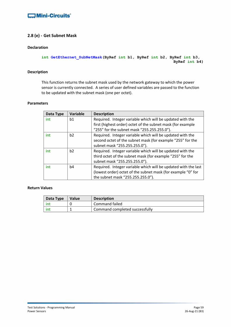
Test Solutions - Programming Manual Page 59 Power Sensors 26-Aug-21 (B3)
2.8 (e) - Get Subnet Mask
Declaration int GetEthernet_SubNetMask(ByRef int b1, ByRef int b2, ByRef int b3,
ByRef int b4)
Description
This function returns the subnet mask used by the network gateway to which the power sensor is currently connected. A series of user defined variables are passed to the function to be updated with the subnet mask (one per octet).
Parameters
Data Type Variable Description
int b1 Required. Integer variable which will be updated with the first (highest order) octet of the subnet mask (for example “255” for the subnet mask “255.255.255.0”).
int b2 Required. Integer variable which will be updated with the second octet of the subnet mask (for example “255” for the subnet mask “255.255.255.0”).
int b2 Required. Integer variable which will be updated with the third octet of the subnet mask (for example “255” for the subnet mask “255.255.255.0”).
int b4 Required. Integer variable which will be updated with the last (lowest order) octet of the subnet mask (for example “0” for the subnet mask “255.255.255.0”).
Return Values
Data Type Value Description
int 0 Command failed
int 1 Command completed successfully

Test Solutions - Programming Manual Page 60 Power Sensors 26-Aug-21 (B3)
Example
See Also
Get Ethernet Configuration Save Subnet Mask
Visual Basic If MyPTE1.GetEthernet_SubNetMask(b1, b2, b3, b4) > 0 Then
MsgBox ("Subnet mask: " & b1 & "." & b2 & "." & b3 & "." & b4)
End If
Visual C++ if (MyPTE1->GetEthernet_SubNetMask(b1, b2, b3, b4) > 0)
{
MessageBox::Show("Subnet mask: " + b1 + "." + b2 + "." + b3 + "."
_ + b4);
} Visual C#
if (MyPTE1.GetEthernet_SubNetMask(b1, b2, b3, b4) > 0)
{
MessageBox.Show("Subnet mask: " + b1 + "." + b2 + "." + b3 + "."
_ + b4);
} Matlab
[status, b1, b2, b3, b4] = MyPTE1.GetEthernet_SubNetMask(b1, b2, b3, b4)
if status > 0
h = msgbox ("Subnet mask: ", b1, ".", b2, ".", b3, ".", b4)
end

Test Solutions - Programming Manual Page 61 Power Sensors 26-Aug-21 (B3)
2.8 (f) - Get TCP/IP Port
Declaration
int GetEthernet_TCPIPPort(ByRef int port)
Description
This function returns the TCP/IP port used by the power sensor for HTTP communication. The default is port 80. Note: Port 23 is reserved for Telnet communication and cannot be set as the HTTP port.
Parameters
Data Type Variable Description
int port Required. Integer variable which will be updated with the TCP/IP port.
Return Values
Data Type Value Description
int 0 Command failed
int 1 Command completed successfully
Example
See Also
Get Ethernet Configuration Save TCP/IP Port
Visual Basic If MyPTE1.GetEthernet_SubNetMask(port) > 0 Then
MsgBox ("Port: " & port)
End If
Visual C++ if (MyPTE1->GetEthernet_SubNetMask(port) > 0)
{
MessageBox::Show("Port: " + port);
} Visual C#
if (MyPTE1.GetEthernet_SubNetMask(port) > 0)
{
MessageBox.Show("Port: " + port);
} Matlab
[status, port] = MyPTE1.GetEthernet_SubNetMask(port)
if status > 0
h = msgbox ("Port: ", port)
end

Test Solutions - Programming Manual Page 62 Power Sensors 26-Aug-21 (B3)
2.8 (g) - Get DHCP Status
Declaration int GetEthernet_UseDHCP()
Description
This function indicates whether the power sensor is using DHCP (dynamic host control protocol), in which case the IP configuration is derived from a network server; or user defined “static” IP settings.
Parameters
Data Type Variable Description
None
Return Values
Data Type Value Description
int 0 DHCP not in use (IP settings are static and manually configured)
int 1 DHCP in use (IP settings are assigned automatically by the network)
Example
See Also
Get Ethernet Configuration Use DHCP
Visual Basic DHCPstatus = MyPTE1.GetEthernet_UseDHCP()
Visual C++ DHCPstatus = MyPTE1->GetEthernet_UseDHCP();
Visual C# DHCPstatus = MyPTE1.GetEthernet_UseDHCP();
Matlab DHCPstatus = MyPTE1.GetEthernet_UseDHCP

Test Solutions - Programming Manual Page 63 Power Sensors 26-Aug-21 (B3)
2.8 (h) - Get Password Status
Declaration int GetEthernet_UsePWD()
Description
This function indicates whether the power sensor is currently configured to require a password for HTTP/Telnet communication.
Parameters
Data Type Variable Description
None
Return Values
Data Type Value Description
int 0 Password not required
int 1 Password required
Example
See Also
Get Password Use Password Set Password
Visual Basic PWDstatus = MyPTE1.GetEthernet_UsePWD()
Visual C++ PWDstatus = MyPTE1->GetEthernet_UsePWD();
Visual C# PWDstatus = MyPTE1.GetEthernet_UsePWD();
Matlab PWDstatus = MyPTE1.GetEthernet_UsePWD

Test Solutions - Programming Manual Page 64 Power Sensors 26-Aug-21 (B3)
2.8 (i) - Get Password
Declaration int GetEthernet_PWD(ByRef string Pwd)
Description
This function returns the current password used by the power sensor for HTTP/Telnet communication. The password will be returned even if the device is not currently configured to require a password.
Parameters
Data Type Variable Description
string Pwd Required. string variable which will be updated with the password.
Return Values
Data Type Value Description
int 0 Command failed
int 1 Command completed successfully
Example
See Also
Get Password Status Use Password Set Password
Visual Basic If MyPTE1.GetEthernet_PWD(pwd) > 0 Then
MsgBox ("Password: " & pwd)
End If
Visual C++ if (MyPTE1->GetEthernet_PWD(pwd) > 0)
{
MessageBox::Show("Password: " + pwd);
} Visual C#
if (MyPTE1.GetEthernet_PWD(pwd) > 0)
{
MessageBox.Show("Password: " + pwd);
} Matlab
[status, pwd] = MyPTE1.GetEthernet_PWD(pwd)
if status > 0
h = msgbox ("Password: ", pwd)
end

Test Solutions - Programming Manual Page 65 Power Sensors 26-Aug-21 (B3)
2.8 (j) - Save IP Address
Declaration int SaveEthernet_IPAddress(int b1, int b2, int b3, int b4)
Description
This function sets a static IP address to be used by the connected power sensor. Note: this could subsequently be overwritten automatically if DHCP is enabled (see Use DHCP).
Parameters
Data Type Variable Description
int IP1 Required. First (highest order) octet of the IP address to set (for example “192” for the IP address “192.168.1.0”).
int IP2 Required. Second octet of the IP address to set (for example “168” for the IP address “192.168.1.0”).
int IP2 Required. Third octet of the IP address to set (for example “1” for the IP address “192.168.1.0”).
int IP4 Required. Last (lowest order) octet of the IP address to set (for example “0” for the IP address “192.168.1.0”).
Return Values
Data Type Value Description
int 0 Command failed
int 1 Command completed successfully
Example
See Also
Get Ethernet Configuration Get IP Address
Visual Basic status = MyPTE1.SaveEthernet_IPAddress(192, 168, 1, 0)
Visual C++ status = MyPTE1->SaveEthernet_IPAddress(192, 168, 1, 0);
Visual C# status = MyPTE1.SaveEthernet_IPAddress(192, 168, 1, 0);
Matlab status = MyPTE1.SaveEthernet_IPAddress(192, 168, 1, 0)

Test Solutions - Programming Manual Page 66 Power Sensors 26-Aug-21 (B3)
2.8 (k) - Save Network Gateway
Declaration int SaveEthernet_NetworkGateway(int b1, int b2, int b3, int b4)
Description
This function sets the IP address of the network gateway to which the power sensor should connect. Note: this could subsequently be overwritten automatically if DHCP is enabled (see Use DHCP).
Parameters
Data Type Variable Description
int IP1 Required. First (highest order) octet of the network gateway IP address (for example “192” for the IP address “192.168.1.0”).
int IP2 Required. Second octet of the network gateway IP address (for example “168” for the IP address “192.168.1.0”).
int IP2 Required. Third octet of the network gateway IP address (for example “1” for the IP address “192.168.1.0”).
int IP4 Required. Last (lowest order) octet of the network gateway IP address (for example “0” for the IP address “192.168.1.0”).
Return Values
Data Type Value Description
int 0 Command failed
int 1 Command completed successfully
Example
See Also
Get Ethernet Configuration Get Network Gateway
Visual Basic status = MyPTE1.SaveEthernet_NetworkGateway(192, 168, 1, 0)
Visual C++ status = MyPTE1->SaveEthernet_NetworkGateway(192, 168, 1, 0);
Visual C# status = MyPTE1.SaveEthernet_NetworkGateway(192, 168, 1, 0);
Matlab status = MyPTE1.SaveEthernet_NetworkGateway(192, 168, 1, 0)

Test Solutions - Programming Manual Page 67 Power Sensors 26-Aug-21 (B3)
2.8 (l) - Save Subnet Mask
Declaration int SaveEthernet_SubnetMask(int b1, int b2, int b3, int b4)
Description
This function sets the subnet mask of the network to which the power sensor should connect. Note: this could subsequently be overwritten automatically if DHCP is enabled (see Use DHCP).
Parameters
Data Type Variable Description
int IP1 Required. First (highest order) octet of the subnet mask (for example “255” for the subnet mask “255.255.255.0”).
int IP2 Required. Second octet of the subnet mask (for example “255” for the subnet mask “255.255.255.0”).
int IP2 Required. Third octet of the subnet mask (for example “255” for the subnet mask “255.255.255.0”).
int IP4 Required. Last (lowest order) octet of the subnet mask (for example “0” for the subnet mask “255.255.255.0”).
Return Values
Data Type Value Description
int 0 Command failed
int 1 Command completed successfully
Example
See Also
Get Ethernet Configuration Get Subnet Mask
Visual Basic status = MyPTE1.SaveEthernet_SubnetMask(255, 255, 255, 0)
Visual C++ status = MyPTE1->SaveEthernet_SubnetMask(255, 255, 255, 0);
Visual C# status = MyPTE1.SaveEthernet_SubnetMask(255, 255, 255, 0);
Matlab status = MyPTE1.SaveEthernet_SubnetMask(255, 255, 255, 0)

Test Solutions - Programming Manual Page 68 Power Sensors 26-Aug-21 (B3)
2.8 (m) - Save TCP/IP Port
Declaration int SaveEthernet_TCPIPPort(int port)
Description
This function sets the TCP/IP port used by the power sensor for HTTP communication. The default is port 80. Note: Port 23 is reserved for Telnet communication and cannot be set as the HTTP port.
Parameters
Data Type Variable Description
int port Required. Numeric value of the TCP/IP port.
Return Values
Data Type Value Description
int 0 Command failed
int 1 Command completed successfully
Example
See Also
Get TCP/IP Port
Visual Basic status = MyPTE1.SaveEthernet_TCPIPPort(70)
Visual C++ status = MyPTE1->SaveEthernet_TCPIPPort(70);
Visual C# status = MyPTE1.SaveEthernet_TCPIPPort(70);
Matlab status = MyPTE1.SaveEthernet_TCPIPPort(70)

Test Solutions - Programming Manual Page 69 Power Sensors 26-Aug-21 (B3)
2.8 (n) - Use DHCP
Declaration int SaveEthernet_UseDHCP(int UseDHCP)
Description
This function enables or disables DHCP (dynamic host control protocol). When enabled the IP configuration of the power sensor is assigned automatically by the network server; when disabled the user defined “static” IP settings apply.
Parameters
Data Type Variable Description
int UseDHCP Required. Integer value to set the DHCP mode: 0 - DHCP disabled (static IP settings used) 1 - DHCP enabled (IP setting assigned by network)
Return Values
Data Type Value Description
int 0 Command failed
int 1 Command completed successfully
Example
See Also
Get DHCP Status
Visual Basic status = MyPTE1.SaveEthernet_UseDHCP(1)
Visual C++ status = MyPTE1->SaveEthernet_UseDHCP(1);
Visual C# status = MyPTE1.SaveEthernet_UseDHCP(1);
Matlab status = MyPTE1.SaveEthernet_UseDHCP(1)

Test Solutions - Programming Manual Page 70 Power Sensors 26-Aug-21 (B3)
2.8 (o) - Use Password
Declaration int SaveEthernet_UsePWD(int UsePwd)
Description
This function enables or disables the password requirement for HTTP/Telnet communication with the power sensor.
Parameters
Data Type Variable Description
int UseDHCP Required. Integer value to set the password mode: 0 – Password not required 1 – Password required
Return Values
Data Type Value Description
int 0 Command failed
int 1 Command completed successfully
Example
See Also
Get Password Status Get Password Set Password
Visual Basic status = MyPTE1.SaveEthernet_UsePWD(1)
Visual C++ status = MyPTE1->SaveEthernet_UsePWD(1);
Visual C# status = MyPTE1.SaveEthernet_UsePWD(1);
Matlab status = MyPTE1.SaveEthernet_UsePWD(1)

Test Solutions - Programming Manual Page 71 Power Sensors 26-Aug-21 (B3)
2.8 (p) - Set Password
Declaration int SaveEthernet_PWD(string Pwd)
Description
This function sets the password used by the power sensor for HTTP/Telnet communication. The password will not affect power sensor operation unless Use Password is also enabled.
Parameters
Data Type Variable Description
string Pwd Required. The password to set (20 characters maximum).
Return Values
Data Type Value Description
int 0 Command failed
int 1 Command completed successfully
Example
See Also
Get Password Status Get Password Use Password
Visual Basic status = MyPTE1.SaveEthernet_PWD("123")
Visual C++ status = MyPTE1->SaveEthernet_PWD("123");
Visual C# status = MyPTE1.SaveEthernet_PWD("123");
Matlab status = MyPTE1.SaveEthernet_PWD("123")
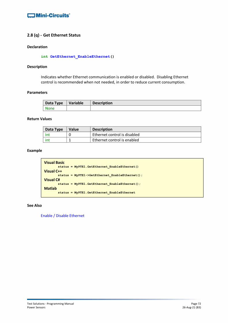
Test Solutions - Programming Manual Page 72 Power Sensors 26-Aug-21 (B3)
2.8 (q) - Get Ethernet Status
Declaration int GetEthernet_EnableEthernet()
Description
Indicates whether Ethernet communication is enabled or disabled. Disabling Ethernet control is recommended when not needed, in order to reduce current consumption.
Parameters
Data Type Variable Description
None
Return Values
Data Type Value Description
int 0 Ethernet control is disabled
int 1 Ethernet control is enabled
Example
See Also
Enable / Disable Ethernet
Visual Basic status = MyPTE1.GetEthernet_EnableEthernet()
Visual C++ status = MyPTE1->GetEthernet_EnableEthernet();
Visual C# status = MyPTE1.GetEthernet_EnableEthernet();
Matlab status = MyPTE1.GetEthernet_EnableEthernet

Test Solutions - Programming Manual Page 73 Power Sensors 26-Aug-21 (B3)
2.8 (r) - Enable / Disable Ethernet
Declaration int SaveEthernet_EnableEthernet(short Enable)
Description
Enable or disable Ethernet communication. Disabling Ethernet control is recommended when not needed, in order to reduce current consumption.
Parameters
Data Type Variable Description
short Enable Required. Integer value to enable / disable Ethernet control: 0 – Ethernet control disabled 1 – Ethernet control enabled
Return Values
Data Type Value Description
int 0 Command failed
int 1 Command completed successfully
Example
See Also
Get Ethernet Status
Visual Basic status = MyPTE1.SaveEthernet_EnableEthernet(1)
Visual C++ status = MyPTE1->SaveEthernet_EnableEthernet(1);
Visual C# status = MyPTE1.SaveEthernet_EnableEthernet(1);
Matlab status = MyPTE1.SaveEthernet_EnableEthernet(1)

Test Solutions - Programming Manual Page 74 Power Sensors 26-Aug-21 (B3)
3 - Operating in a Linux Environment via USB When connected by USB, the computer will recognize the power meter as a Human Interface Device (HID). In this mode of operation the following USB interrupt codes can be used. Alternatively, the device can be operated over an Ethernet TCP/IP Network (see Ethernet Control over IP Networks for details).
To open a connection to the power sensor, the Vendor ID and Product ID are required:
• Mini-Circuits Vendor ID: 0x20CE
• Power Sensor Product ID: 0x11 Communication with the power sensor is carried out by way of USB Interrupt. The transmitted and received buffer sizes are 64 Bytes each:
• Transmit Array = [Byte 0][Byte1][Byte2]…[Byte 63]
• Returned Array = [Byte 0][Byte1][Byte2]…[Byte 63] In most cases, the full 64 byte buffer size is not needed so any unused bytes become “don’t care” bytes; they can take on any value without affecting the operation of the power sensor. Worked examples can be found in the Programming Examples & Troubleshooting Guide, downloadable from the Mini-Circuits website. The examples use the libhid and libusb libraries to interface with the programmable attenuator as a USB HID (Human Interface Device).
3.1 - Interrupts - General Functions
# Description Command Code (Byte 0)
a Get Device Model Name 104
b Get Device Serial Number 105
c Set Measurement Mode 15
d Read Power 102
e Get Internal Temperature 103
f Get Firmware 99
g Send SCPI Command 42 or 121

Test Solutions - Programming Manual Page 75 Power Sensors 26-Aug-21 (B3)
3.1 (a) - Get Device Model Name
Description
Returns the full Mini-Circuits part number of the connected power sensor.
Transmit Array
Byte Data Description
0 104 Interrupt code for Get Device Model Name
1- 63 Not significant “Don’t care” bytes, can be any value
Returned Array
Byte Data Description
0 104 Interrupt code for Get Device Model Name
1 to (n-1)
Model Name Series of bytes containing the ASCII code for each character in the model name
n 0 Zero value byte to indicate the end of the model name
(n+1) to 63
Not significant “Don’t care” bytes, can be any value
Example
The following array would be returned for Mini-Circuits’ PWR-8FS power sensor. See Appendix A for conversions between decimal, binary and ASCII characters.
Byte Byte 0 Byte 1 Byte 2 Byte 3 Byte 4 Byte 5
Description Code Char 1 Char 2 Char 3 Char 4 Char 5
Value 104 80 87 82 45 56
ASCII Character N/A P W R - 8
Byte Byte 6 Byte 7 Byte 8
Description Char 6 Char 7 End
Marker
Value 70 83 0
ASCII Character F S N/A
See Also
Get Device Serial Number
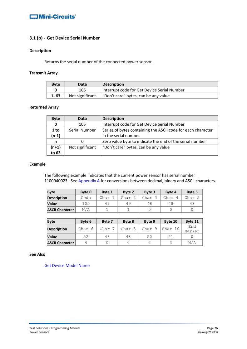
Test Solutions - Programming Manual Page 76 Power Sensors 26-Aug-21 (B3)
3.1 (b) - Get Device Serial Number
Description
Returns the serial number of the connected power sensor.
Transmit Array
Byte Data Description
0 105 Interrupt code for Get Device Serial Number
1- 63 Not significant “Don’t care” bytes, can be any value
Returned Array
Byte Data Description
0 105 Interrupt code for Get Device Serial Number
1 to (n-1)
Serial Number Series of bytes containing the ASCII code for each character in the serial number
n 0 Zero value byte to indicate the end of the serial number
(n+1) to 63
Not significant “Don’t care” bytes, can be any value
Example
The following example indicates that the current power sensor has serial number 1100040023. See Appendix A for conversions between decimal, binary and ASCII characters.
Byte Byte 0 Byte 1 Byte 2 Byte 3 Byte 4 Byte 5
Description Code Char 1 Char 2 Char 3 Char 4 Char 5
Value 105 49 49 48 48 48
ASCII Character N/A 1 1 0 0 0
Byte Byte 6 Byte 7 Byte 8 Byte 9 Byte 10 Byte 11
Description Char 6 Char 7 Char 8 Char 9 Char 10 End
Marker
Value 52 48 48 50 51 0
ASCII Character 4 0 0 2 3 N/A
See Also
Get Device Model Name

Test Solutions - Programming Manual Page 77 Power Sensors 26-Aug-21 (B3)
3.1 (c) - Set Measurement Mode
Description
Sets the measurement mode of the power sensor between "low noise" and "fast sampling" modes; the default is "low noise" mode. Additionally, "fastest sampling" mode is also available for PWR-8FS. See the individual model datasheets for specifications. This function does not apply to PWR-6G (now discontinued).
Transmit Array
Byte Data Description
0 15 Interrupt code for Set Measurement Mode
1 Mode Integer value to set the required mode: 0 = Low noise mode 1 = Fast sampling mode 2 = Fastest sampling mode (PWR-8FS only)
2- 63 Not significant “Don’t care” bytes, can be any value
Returned Array
Byte Data Description
0 15 Interrupt code for Set Measurement Mode
1 to 63 Not significant “Don’t care” bytes, can be any value
Example
Byte Data Description
0 15 Interrupt code for Set Measurement Mode
1 1 Set power sensor to "fast sampling" mode
2- 63 Not significant “Don’t care” bytes, can be any value

Test Solutions - Programming Manual Page 78 Power Sensors 26-Aug-21 (B3)
3.1 (d) - Read Power
Description
Returns the sensor power measurement based on a user specified compensation frequency. The power value (in dBm) is represented in BYTE1 to BYTE6 of the returned array as a series of ASCII character codes in the format “+00.00”.
Transmit Array
Byte Data Description
0 102 Interrupt code for Read Power
1 Frequency_1 The compensation frequency to be used for the power reading, split over 2 bytes: Frequency_1 = INT (FREQUENCY / 256)
2 Frequency_2 The compensation frequency to be used for the power reading, split over 2 bytes: Frequency_2 = FREQUENCY - (Frequency_1 * 256)
3 Freq_Units ASCII character code representing the units for the compensation frequency, the 2 options are: 75 = ASCII code for "K" (frequency units are KHz) 77 = ASCII code for "M" (frequency units are MHz)
4- 63 Not significant “Don’t care” bytes, can be any value
Returned Array
Byte Data Description
0 102 Interrupt code for Read Power
1 Power_1 ASCII character code for the first character of the power reading
2 Power_2 ASCII character code for the second character of the power reading
3 Power_3 ASCII character code for the third character of the power reading
4 Power_4 ASCII character code for the fourth character of the power reading
5 Power_5 ASCII character code for the fifth character of the power reading
6 Power_6 ASCII character code for the sixth character of the power reading
7 to 63 Not significant “Don’t care” bytes, can be any value

Test Solutions - Programming Manual Page 79 Power Sensors 26-Aug-21 (B3)
Example
The following transmit array would be sent to read the power for an expected signal at 1250 MHz:
Byte Data Description
0 102 Interrupt code for Read Power
1 4 Frequency_1 = INT (1250 / 256)
2 226 Frequency_2 = 1250 - (4 * 256)
3 77 ASCII code for "M" (frequency units are MHz)
4- 63 Not significant “Don’t care” bytes, can be any value
The following array would be returned to indicate a power reading of -10.65dBm:
Byte Data Description
0 102 Interrupt code for Read Power
1 45 ASCII character code for "-"
2 49 ASCII character code for "1"
3 48 ASCII character code for "0"
4 46 ASCII character code for "."
5 54 ASCII character code for "6"
6 53 ASCII character code for "5"
7 to 63 Not significant “Don’t care” bytes, can be any value

Test Solutions - Programming Manual Page 80 Power Sensors 26-Aug-21 (B3)
3.1 (e) - Get Internal Temperature
Description
This function returns the internal temperature of the power sensor in degrees Celsius, to two decimal places.
Transmit Array
Byte Data Description
0 103 Interrupt code for Get Internal Temperature
1-63 Not significant “Don’t care” bytes, can be any value
Returned Array
Byte Data Description
0 103 Interrupt code for Get Internal Temperature
1 Temp_1 ASCII character code for the first character of the temperature reading
2 Temp_2 ASCII character code for the second character of the temperature reading
3 Temp_3 ASCII character code for the third character of the temperature reading
4 Temp_4 ASCII character code for the fourth character of the temperature reading
5 Temp_5 ASCII character code for the fifth character of the temperature reading
6 Temp_6 ASCII character code for the sixth character of the temperature reading
7-63 Not significant “Don’t care” bytes, can be any value
Example
The below returned array would indicate a temperature of +28.43°C:
Byte Data Description
0 103 Interrupt code for Get Internal Temperature
1 43 ASCII character code for "+"
2 50 ASCII character code for "2"
3 56 ASCII character code for "8"
4 46 ASCII character code for "."
5 52 ASCII character code for "4"
6 51 ASCII character code for "3"
7 to 63 Not significant “Don’t care” bytes, can be any value

Test Solutions - Programming Manual Page 81 Power Sensors 26-Aug-21 (B3)
3.1 (f) - Get Firmware
Description
Returns the internal firmware version of the power sensor. Transmit Array
Byte Data Description
0 99 Interrupt code for Get Firmware
1- 63 Not significant “Don’t care” bytes, can be any value
Returned Array
Byte Data Description
0 99 Interrupt code for Get Firmware
1 Reserved Internal code for factory use only
2 Reserved Internal code for factory use only
3 Reserved Internal code for factory use only
4 Reserved Internal code for factory use only
5 Firmware Letter
ASCII code for the first character in the firmware revision identifier
6 Firmware Number
ASCII code for the second character in the firmware revision identifier
7-63 Not significant “Don’t care” bytes, could be any value
Example
The following returned array indicates that the power sensor has firmware version C3:
Byte Data Description
0 99 Interrupt code for Get Firmware
1 55 Internal code for factory use only
2 52 Internal code for factory use only
3 83 Internal code for factory use only
4 87 Internal code for factory use only
5 67 ASCII code for the letter “C”
6 51 ASCII code for the number 3
7-63 Not significant “Don’t care” bytes, could be any value

Test Solutions - Programming Manual Page 82 Power Sensors 26-Aug-21 (B3)
3.1 (g) - Send SCPI Command
Description
Sends a SCPI command to the power sensor and collects the returned acknowledgement. SCPI (Standard Commands for Programmable Instruments) is a common method for communicating with and controlling instrumentation products.
Transmit Array
Byte Data Description
0 42 or 121 Interrupt code for Send SCPI Command
1 SCPI_Length The length (number of ASCII characters) of the SCPI string to send
2 to 63 SCPI Transmit String
The SCPI command to be sent represented as a series of ASCII character codes, one character code per byte
Returned Array
Byte Data Description
0 42 or 121 Interrupt code for Send SCPI Command
1 SCPI_Length The length (number of ASCII characters) of the SCPI command sent in the transmit array
2 to 7 Transmit_Array Bytes 2 to 7 of the transmit array repeated
8 to (n-1)
SCPI Return String
The SCPI return string, one character per byte, represented as ASCII character codes
n 0 Zero value byte to indicate the end of the SCPI return string
(n+1) to 63
Not significant "Don’t care" bytes, could be any value
Example (Get Model Name)
The SCPI command to request the model name is :MN? (see Get Model Name) The ASCII character codes representing the 4 characters in this command should be sent in bytes 2 to 5 of the transmit array as follows:
Byte Data Description
0 42 Interrupt code for Send SCPI Command
1 4 Length of the SCPI command (four ASCII characters)
2 49 ASCII character code for :
3 77 ASCII character code for M
4 78 ASCII character code for N
5 63 ASCII character code for ?
See Also
SCPI Functions

Test Solutions - Programming Manual Page 83 Power Sensors 26-Aug-21 (B3)
3.2 - Interrupts - Ethernet Configuration Functions (RC Models Only)
Description Command Code
Byte 0 Byte 1
a Set Static IP Address 250 201
b Set Static Subnet Mask 250 202
c Set Static Network Gateway 250 203
d Set HTTP Port 250 204
e Use Password 250 205
f Set Password 250 206
g Use DHCP 250 207
h Get Static IP Address 251 201
i Get Static Subnet Mask 251 202
j Get Static Network Gateway 251 203
k Get HTTP Port 251 204
l Get Password Status 251 205
m Get Password 251 206
n Get DHCP Status 251 207
o Get Dynamic Ethernet Configuration 253
p Get MAC Address 252
q Enable / Disable Ethernet 250 208
r Reset Ethernet Configuration 101 101

Test Solutions - Programming Manual Page 84 Power Sensors 26-Aug-21 (B3)
3.2 (a) - Set Static IP Address
Description
Sets the static IP address to be used when DHCP (dynamic host control protocol) is disabled. Transmit Array
Byte Data Description
0 250 Interrupt code for Set Ethernet Configuration
1 201 Interrupt code for Set IP Address
2 IP_Byte0 First byte of IP address
3 IP_Byte1 Second byte of IP address
4 IP_Byte2 Third byte of IP address
5 IP_Byte3 Fourth byte of IP address
6 - 63 Not significant Any value
Returned Array
Byte Data Description
0 250 Interrupt code for Set Ethernet Configuration
1 - 63 Not significant Any value
Example
To set the static IP address to 192.168.100.100, the transmit array is:
Byte Data Description
0 250 Interrupt code for Set Ethernet Configuration
1 201 Interrupt code for Set IP Address
2 192 First byte of IP address
3 168 Second byte of IP address
4 100 Third byte of IP address
5 100 Fourth byte of IP address
See Also
Use DHCP Get Static IP Address Reset Ethernet Configuration

Test Solutions - Programming Manual Page 85 Power Sensors 26-Aug-21 (B3)
3.2 (b) - Set Static Subnet Mask
Description
Sets the static subnet mask to be used when DHCP (dynamic host control protocol) is disabled.
Transmit Array
Byte Data Description
0 250 Interrupt code for Set Ethernet Configuration
1 202 Interrupt code for Set Subnet Mask
2 IP_Byte0 First byte of subnet mask
3 IP_Byte1 Second byte of subnet mask
4 IP_Byte2 Third byte of subnet mask
5 IP_Byte3 Fourth byte of subnet mask
6 - 63 Not significant Any value
Returned Array
Byte Data Description
0 250 Interrupt code for Set Ethernet Configuration
1 - 63 Not significant Any value
Example
To set the static subnet mask to 255.255.255.0, the transmit array is:
Byte Data Description
0 250 Interrupt code for Set Ethernet Configuration
1 202 Interrupt code for Set Subnet Mask
2 255 First byte of subnet mask
3 255 Second byte of subnet mask
4 255 Third byte of subnet mask
5 0 Fourth byte of subnet mask
See Also
Use DHCP Get Static Subnet Mask Reset Ethernet Configuration

Test Solutions - Programming Manual Page 86 Power Sensors 26-Aug-21 (B3)
3.2 (c) - Set Static Network Gateway
Description
Sets the network gateway IP address to be used when DHCP (dynamic host control protocol) is disabled.
Transmit Array
Byte Data Description
0 250 Interrupt code for Set Ethernet Configuration
1 203 Interrupt code for Set Network Gateway
2 IP_Byte0 First byte of network gateway IP address
3 IP_Byte1 Second byte of network gateway IP address
4 IP_Byte2 Third byte of network gateway IP address
5 IP_Byte3 Fourth byte of network gateway IP address
6 - 63 Not significant Any value
Returned Array
Byte Data Description
0 250 Interrupt code for Set Ethernet Configuration
1 - 63 Not significant Any value
Example
To set the static IP address to 192.168.100.0, the transmit array is:
Byte Data Description
0 250 Interrupt code for Set Ethernet Configuration
1 203 Interrupt code for Set Network Gateway
2 192 First byte of IP address
3 168 Second byte of IP address
4 100 Third byte of IP address
5 0 Fourth byte of IP address
See Also
Use DHCP Get Static Network Gateway Reset Ethernet Configuration

Test Solutions - Programming Manual Page 87 Power Sensors 26-Aug-21 (B3)
3.2 (d) - Set HTTP Port
Description
Sets the port to be used for HTTP communication (default is port 80). Transmit Array
Byte Data Description
0 250 Interrupt code for Set Ethernet Configuration
1 204 Interrupt code for Set HTTP Port
2 Port_Byte0 First byte (MSB) of HTTP port value: Port_Byte0 = INTEGER (Port / 256)
3 Port_Byte1 Second byte (LSB) of HTTP port value: Port_byte1 = Port - (Port_Byte0 * 256)
4 - 63 Not significant Any value
Returned Array
Byte Data Description
0 250 Interrupt code for Set Ethernet Configuration
1 - 63 Not significant Any value
Example
To set the HTTP port to 8080, the transmit array is:
Byte Data Description
0 250 Interrupt code for Set Ethernet Configuration
1 204 Interrupt code for Set HTTP Port
2 31 Port_Byte0 = INTEGER (8080 / 256)
3 144 Port_byte1 = 8080 - (31 * 256)
See Also
Get HTTP Port Reset Ethernet Configuration

Test Solutions - Programming Manual Page 88 Power Sensors 26-Aug-21 (B3)
3.2 (e) - Use Password
Description
Enables or disables the requirement to password protect the HTTP / Telnet communication. Transmit Array
Byte Data Description
0 250 Interrupt code for Set Ethernet Configuration
1 205 Interrupt code for Use Password
2 PW_Mode 0 = password not required (default) 1 = password required
3 - 63 Not significant Any value
Returned Array
Byte Data Description
0 250 Interrupt code for Set Ethernet Configuration
1 - 63 Not significant Any value
Example
To enable the password requirement for Ethernet communication, the transmit array is:
Byte Data Description
0 250 Interrupt code for Set Ethernet Configuration
1 205 Interrupt code for Use Password
2 1 Enable password requirement
See Also
Set Password Get Password Status Get Password Reset Ethernet Configuration

Test Solutions - Programming Manual Page 89 Power Sensors 26-Aug-21 (B3)
3.2 (f) - Set Password
Description
Sets the password to be used for Ethernet communication (when password security is enabled, maximum 20 characters.
Transmit Array
Byte Data Description
0 250 Interrupt code for Set Ethernet Configuration
1 206 Interrupt code for Set Password
2 PW_Length Length (number of characters) of the password
3 to n PW_Char Series of ASCII character codes (1 per byte) for the Ethernet password
n + 1 to 63
Not significant Any value
Returned Array
Byte Data Description
0 250 Interrupt code for Set Ethernet Configuration
1 to 63 Not significant Any value
Example
To set the password to Pass_123, the transmit array is:
Byte Data Description
0 250 Interrupt code for Set Ethernet Configuration
1 206 Interrupt code for Set Password
2 8 Length of password (8 characters)
3 80 ASCII character code for P
4 97 ASCII character code for a
5 115 ASCII character code for s
6 115 ASCII character code for s
7 95 ASCII character code for _
8 49 ASCII character code for 1
9 50 ASCII character code for 2
10 51 ASCII character code for 3
See Also
Use Password Get Password Status Get Password Reset Ethernet Configuration

Test Solutions - Programming Manual Page 90 Power Sensors 26-Aug-21 (B3)
3.2 (g) - Use DHCP
Description
Enables or disables DHCP (dynamic host control protocol). With DHCP enabled, the attenuators Ethernet / IP configuration is assigned by the network and any user defined static IP settings are ignored. With DHCP disabled, the user defined static IP settings are used.
Transmit Array
Byte Data Description
0 250 Interrupt code for Set Ethernet Configuration
1 207 Interrupt code for Use DHCP
2 DHCP_Mode 0 = DCHP disabled (static IP settings in use) 1 = DHCP enabled (default - dynamic IP in use)
3 - 63 Not significant Any value
Returned Array
Byte Data Description
0 250 Interrupt code for Set Ethernet Configuration
1 - 63 Not significant Any value
Example
To enable DHCP for Ethernet communication, the transmit array is:
Byte Data Description
0 250 Interrupt code for Set Ethernet Configuration
1 207 Interrupt code for Use DHCP
2 1 Enable DHCP
See Also
Use DHCP Get DHCP Status Get Dynamic Ethernet Configuration Reset Ethernet Configuration

Test Solutions - Programming Manual Page 91 Power Sensors 26-Aug-21 (B3)
3.2 (h) - Get Static IP Address
Description
Gets the static IP address (configured by the user) to be used when DHCP (dynamic host control protocol) is disabled.
Transmit Array
Byte Data Description
0 251 Interrupt code for Get Ethernet Configuration
1 201 Interrupt code for Get IP Address
2 - 63 Not significant Any value
Returned Array
Byte Data Description
0 251 Interrupt code for Get Ethernet Configuration
1 IP_Byte0 First byte of IP address
2 IP_Byte1 Second byte of IP address
3 IP_Byte2 Third byte of IP address
4 IP_Byte3 Fourth byte of IP address
5 - 63 Not significant Any value
Example
The following returned array would indicate that a static IP address of 192.168.100.100 has been configured:
Byte Data Description
0 251 Interrupt code for Get Ethernet Configuration
1 192 First byte of IP address
2 168 Second byte of IP address
3 100 Third byte of IP address
4 100 Fourth byte of IP address
See Also
Use DHCP Set Static IP Address

Test Solutions - Programming Manual Page 92 Power Sensors 26-Aug-21 (B3)
3.2 (i) - Get Static Subnet Mask
Description
Gets the subnet mask (configured by the user) to be used when DHCP (dynamic host control protocol) is disabled.
Transmit Array
Byte Data Description
0 251 Interrupt code for Get Ethernet Configuration
1 202 Interrupt code for Get Subnet Mask
2 - 63 Not significant Any value
Returned Array
Byte Data Description
0 251 Interrupt code for Get Ethernet Configuration
1 IP_Byte0 First byte of subnet mask
2 IP_Byte1 Second byte of subnet mask
3 IP_Byte2 Third byte of subnet mask
4 IP_Byte3 Fourth byte of subnet mask
5 - 63 Not significant Any value
Example
The following returned array would indicate that a subnet mask of 255.255.255.0 has been configured:
Byte Data Description
0 251 Interrupt code for Get Ethernet Configuration
1 255 First byte of subnet mask
2 255 Second byte of subnet mask
3 255 Third byte of subnet mask
4 0 Fourth byte of subnet mask
See Also
Use DHCP Set Static Subnet Mask

Test Solutions - Programming Manual Page 93 Power Sensors 26-Aug-21 (B3)
3.2 (j) - Get Static Network Gateway
Description
Gets the static IP address (configured by the user) of the network gateway to be used when DHCP (dynamic host control protocol) is disabled.
Transmit Array
Byte Data Description
0 251 Interrupt code for Get Ethernet Configuration
1 203 Interrupt code for Get Network Gateway
2 - 63 Not significant Any value
Returned Array
Byte Data Description
0 251 Interrupt code for Get Ethernet Configuration
1 IP_Byte0 First byte of IP address
2 IP_Byte1 Second byte of IP address
3 IP_Byte2 Third byte of IP address
4 IP_Byte3 Fourth byte of IP address
5 - 63 Not significant Any value
Example
The following returned array would indicate that a network gateway IP address of 192.168.100.0 has been configured:
Byte Data Description
0 251 Interrupt code for Get Ethernet Configuration
1 192 First byte of IP address
2 168 Second byte of IP address
3 100 Third byte of IP address
4 0 Fourth byte of IP address
See Also
Use DHCP Set Static Network Gateway

Test Solutions - Programming Manual Page 94 Power Sensors 26-Aug-21 (B3)
3.2 (k) - Get HTTP Port
Description
Gets the port to be used for HTTP communication (default is port 80). Transmit Array
Byte Data Description
0 251 Interrupt code for Get Ethernet Configuration
1 204 Interrupt code for Get HTTP Port
2 - 63 Not significant Any value
Returned Array
Byte Data Description
0 251 Interrupt code for Get Ethernet Configuration
1 Port_Byte0 First byte (MSB) of HTTP port value:
2 Port_Byte1 Second byte (LSB) of HTTP port value: Port = (Port_Byte0 * 256) + Port_Byte1
3 - 63 Not significant Any value
Example
The following returned array would indicate that the HTTP port has been configured as 8080:
Byte Data Description
0 251 Interrupt code for Get Ethernet Configuration
1 31
2 144 Port = (31 * 256) + 144 = 8080
See Also
Set HTTP Port

Test Solutions - Programming Manual Page 95 Power Sensors 26-Aug-21 (B3)
3.2 (l) - Get Password Status
Description
Checks whether the attenuators has been configured to require a password for HTTP / Telnet communication.
Transmit Array
Byte Data Description
0 251 Interrupt code for Get Ethernet Configuration
1 205 Interrupt code for Get Password Status
2 - 63 Not significant Any value
Returned Array
Byte Data Description
0 251 Interrupt code for Set Ethernet Configuration
1 PW_Mode 0 = password not required (default) 1 = password required
2 - 63 Not significant Any value
Example
The following returned array indicates that password protection is enabled:
Byte Data Description
0 251 Interrupt code for Get Ethernet Configuration
1 1 Password protection enabled
See Also
Use Password Set Password Get Password

Test Solutions - Programming Manual Page 96 Power Sensors 26-Aug-21 (B3)
3.2 (m) - Get Password
Description
Gets the password to be used for Ethernet communication (when password security is enabled, maximum 20 characters.
Transmit Array
Byte Data Description
0 251 Interrupt code for Get Ethernet Configuration
1 206 Interrupt code for Get Password
2 to 63 Not significant Any value
Returned Array
Byte Data Description
0 251 Interrupt code for Get Ethernet Configuration
1 PW_Length Length (number of characters) of the password
2 to n PW_Char Series of ASCII character codes (1 per byte) for the Ethernet password
n to 63 Not significant Any value
Example
The following returned array indicated that the password has been set to Pass_123:
Byte Data Description
0 251 Interrupt code for Get Ethernet Configuration
1 8 Length of password (8 characters)
2 80 ASCII character code for P
3 97 ASCII character code for a
4 115 ASCII character code for s
5 115 ASCII character code for s
6 95 ASCII character code for _
7 49 ASCII character code for 1
8 50 ASCII character code for 2
9 51 ASCII character code for 3
See Also
Use Password Set Password Get Password Status

Test Solutions - Programming Manual Page 97 Power Sensors 26-Aug-21 (B3)
3.2 (n) - Get DHCP Status
Description
Checks whether DHCP (dynamic host control protocol) is enabled or disabled. With DHCP enabled, the attenuators Ethernet / IP configuration is assigned by the network and any user defined static IP settings are ignored. With DHCP disabled, the user defined static IP settings are used.
Transmit Array
Byte Data Description
0 251 Interrupt code for Get Ethernet Configuration
1 207 Interrupt code for Get DHCP Status
2 - 63 Not significant Any value
Returned Array
Byte Data Description
0 251 Interrupt code for Set Ethernet Configuration
1 DCHP_Mode 0 = DCHP disabled (static IP settings in use) 1 = DHCP enabled (default - dynamic IP in use)
2 - 63 Not significant Any value
Example
The following returned array indicates that DHCP is enabled:
Byte Data Description
0 251 Interrupt code for Get Ethernet Configuration
1 1 DHCP enabled
See Also
Use DHCP Get Dynamic Ethernet Configuration

Test Solutions - Programming Manual Page 98 Power Sensors 26-Aug-21 (B3)
3.2 (o) - Get Dynamic Ethernet Configuration
Description
Returns the IP address, subnet mask and default gateway currently used by the device. If DHCP is enabled then these values are assigned by the network DHCP server. If DHCP is disabled then these values are the static configuration defined by the user.
Transmit Array
Byte Data Description
0 253 Interrupt code for Get Dynamic Ethernet Configuration
1 - 63 Not significant Any value
Returned Array
Byte Data Description
0 253 Interrupt code for Get Dynamic Ethernet Configuration
1 IP_Byte0 First byte of IP address
2 IP_Byte1 Second byte of IP address
3 IP_Byte2 Third byte of IP address
4 IP_Byte3 Fourth byte of IP address
5 SM_Byte0 First byte of subnet mask
6 SM_Byte1 Second byte of subnet mask
7 SM_Byte2 Third byte of subnet mask
8 SM_Byte3 Fourth byte of subnet mask
9 NG_Byte0 First byte of network gateway IP address
10 NG_Byte1 Second byte of network gateway IP address
11 NG_Byte2 Third byte of network gateway IP address
12 NG_Byte3 Fourth byte of network gateway IP address
13 - 63 Not significant Any value

Test Solutions - Programming Manual Page 99 Power Sensors 26-Aug-21 (B3)
Example
The following returned array would indicate the below Ethernet configuration is active:
• IP Address: 192.168.100.100
• Subnet Mask: 255.255.255.0
• Network Gateway: 192.168.100.0
Byte Data Description
0 253 Interrupt code for Get Dynamic Ethernet Configuration
1 192 First byte of IP address
2 168 Second byte of IP address
3 100 Third byte of IP address
4 100 Fourth byte of IP address
5 255 First byte of subnet mask
6 255 Second byte of subnet mask
7 255 Third byte of subnet mask
8 0 Fourth byte of subnet mask
9 192 First byte of network gateway IP address
10 168 Second byte of network gateway IP address
11 100 Third byte of network gateway IP address
12 0 Fourth byte of network gateway IP address
See Also
Use DHCP Get DHCP Status
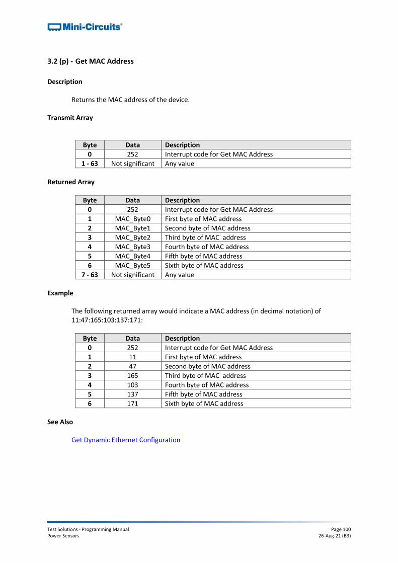
Test Solutions - Programming Manual Page 100 Power Sensors 26-Aug-21 (B3)
3.2 (p) - Get MAC Address
Description
Returns the MAC address of the device. Transmit Array
Byte Data Description
0 252 Interrupt code for Get MAC Address
1 - 63 Not significant Any value
Returned Array
Byte Data Description
0 252 Interrupt code for Get MAC Address
1 MAC_Byte0 First byte of MAC address
2 MAC_Byte1 Second byte of MAC address
3 MAC_Byte2 Third byte of MAC address
4 MAC_Byte3 Fourth byte of MAC address
5 MAC_Byte4 Fifth byte of MAC address
6 MAC_Byte5 Sixth byte of MAC address
7 - 63 Not significant Any value
Example
The following returned array would indicate a MAC address (in decimal notation) of 11:47:165:103:137:171:
Byte Data Description
0 252 Interrupt code for Get MAC Address
1 11 First byte of MAC address
2 47 Second byte of MAC address
3 165 Third byte of MAC address
4 103 Fourth byte of MAC address
5 137 Fifth byte of MAC address
6 171 Sixth byte of MAC address
See Also
Get Dynamic Ethernet Configuration

Test Solutions - Programming Manual Page 101 Power Sensors 26-Aug-21 (B3)
3.2 (q) - Enable / Disable Ethernet
Description
Enable or disable Ethernet communication. Disabling Ethernet control is recommended when not needed, in order to reduce current consumption.
Transmit Array
Byte Data Description
0 250 Interrupt code for Set Ethernet Configuration
1 208 Interrupt code for Enable / Disable Ethernet
2 Mode 0 = Ethernet disabled 1 = Ethernet enabled
3 - 63 Not significant Any value
Returned Array
Byte Data Description
0 250 Interrupt code for Set Ethernet Configuration
1 - 63 Not significant Any value
Example
To enable Ethernet control, the transmit array is:
Byte Data Description
0 250 Interrupt code for Set Ethernet Configuration
1 208 Interrupt code for Enable / Disable Ethernet
2 1 Enable Ethernet control

Test Solutions - Programming Manual Page 102 Power Sensors 26-Aug-21 (B3)
3.2 (r) - Reset Ethernet Configuration
Description
Forces the device to reset and adopt the latest Ethernet configuration. Must be sent after any changes are made to the configuration.
Transmit Array
Byte Data Description
0 101 Reset Ethernet configuration sequence
1 101 Reset Ethernet configuration sequence
2 102 Reset Ethernet configuration sequence
3 103 Reset Ethernet configuration sequence
4 - 63 Not significant Any value
Returned Array
Byte Data Description
0 101 Confirmation of reset Ethernet configuration sequence
1 - 63 Not significant Any value
Test Solutions - Programming Manual Page 103 Power Sensors 26-Aug-21 (B3)
4 - Ethernet Control over IP Networks
The Mini-Circuits RC series of power sensors have a RJ45 connector for remote control over Ethernet TCP/IP networks. HTTP (Get/Post commands) and Telnet communication are supported. UDP transmission is also supported for discovering available power sensors on the network. The device can be configured manually with a static IP address or automatically by the network using DHCP (Dynamic Host Control Protocol):
• Dynamic IP (factory default setting) o Subnet Mask, Network Gateway and local IP Address are assigned by the
network server on each connection o The only user controllable parameters are:
▪ TCP/IP Port for HTTP communication (the default is port 80) ▪ Password (up to 20 characters; default is no password)
• Static IP o All parameters must be specified by the user:
▪ IP Address (must be a legal and unique address on the local network) ▪ Subnet Mask (subnet mask of the local network) ▪ Network gateway (the IP address of the network gateway/router) ▪ TCP/IP Port for HTTP communication (the default is port 80) ▪ Password (up to 20 characters; default is no password)
Notes:
1. The TCP/IP port must be included in every HTTP command to the power sensor unless the default port 80 is used
2. The password must be included in every HTTP command to the power sensor if password security is enabled
3. Port 23 is reserved for Telnet communication 4. The device draws DC power through the USB type B connector; this can be
connected to a computer or the AC mains adapter
4.1 - Configuring Ethernet Settings via USB
The sensor must be connected via the USB interface in order to configure the Ethernet settings. Following initial configuration, the device can be controlled via the Ethernet interface with no further need for a USB connection. The API DLL provides the functionality for configuring the Ethernet settings over a USB connection (see DLL Functions for Ethernet Configuration for full details).

Test Solutions - Programming Manual Page 104 Power Sensors 26-Aug-21 (B3)
4.2 - Ethernet Communication Methodology
Communication over Ethernet is accomplished using HTTP (Get/Post commands) or Telnet to send SCPI commands. The HTTP and Telnet protocols are both commonly supported and simple to implement in most programming languages. Any Internet browser can be used as a console/tester for HTTP control by typing the commands/queries directly into the address bar. The SCPI commands that can be sent to Mini-Circuits RC power sensor series are detailed in the SCPI Command Set for Ethernet Control section.
4.2 (a) - Setting Power Sensor Properties Using HTTP and SCPI
The basic format of the HTTP command to set the power sensor is:
http://ADDRESS:PORT/PWD;COMMAND Where
• http:// is required
• ADDRESS = IP address (required)
• PORT = TCP/IP port (can be omitted if port 80 is used)
• PWD = Password (can be omitted if password security is not enabled)
• COMMAND = Command to send to the power sensor Example 1:
http://192.168.100.100:800/PWD=123;:FREQ:1000 Explanation:
• The power sensor has IP address 192.168.100.100 and uses port 800
• Password security is enabled and set to “123”
• The command is to set the compensation frequency to 1000MHz (see below for the full explanation of all commands/queries)
Example 2:
http://10.10.10.10/:TEMP:FORMAT:F Explanation:
• The power sensor has IP address 10.10.10.10 and uses the default port 80
• Password security is disabled
• The command is to set the temperature format to Fahrenheit (see below for the full explanation of all commands/queries)
Test Solutions - Programming Manual Page 105 Power Sensors 26-Aug-21 (B3)
4.2 (b) - Querying Power Sensor Properties Using HTTP and SCPI
The basic format of the HTTP command to query the power sensor is:
http://ADDRESS:PORT/PWD;QUERY? Where
• http:// is required
• ADDRESS = IP address (required)
• PORT = TCP/IP port (can be omitted if port 80 is used)
• PWD = Password (can be omitted if password is security is not enabled)
• QUERY? = Query to send to the power sensor Example 1:
http://192.168.100.100:800/PWD=123;:MN? Explanation:
• The power sensor has IP address 192.168.100.100 and uses port 800
• Password security is enabled and set to “123”
• The query is to return the model name of the power sensor (see below for the full explanation of all commands/queries)
Example 2:
http://10.10.10.10/:POWER? Explanation:
• The power sensor has IP address 10.10.10.10 and uses the default port 80
• Password security is disabled
• The query is to return the current power reading (see below for the full explanation of all commands/queries)
The device will return the result of the query as a string of ASCII characters.

Test Solutions - Programming Manual Page 106 Power Sensors 26-Aug-21 (B3)
4.2 (c) - Communication Using Telnet and SCPI
Communication with the device is started by creating a Telnet connection to the power sensor IP address. On successful connection the “line feed” character will be returned. If the power sensor has a password enabled then this must be sent as the first command after connection. The full list of all SCPI commands and queries is detailed in the following sections. A basic example of the Telnet communication structure using the Windows Telnet Client is summarized below: 1) Set up Telnet connection to an power sensor with IP address 192.168.9.73
2) The “line feed” character is returned indicating the connection was successful:
3) The password (if enabled) must be sent as the first command; a return value of 1 indicates success:
4) Any number of commands and queries can be sent as needed:

Test Solutions - Programming Manual Page 107 Power Sensors 26-Aug-21 (B3)
4.3 - Device Discovery Using UDP
In addition to HTTP and Telnet, the RC series of Ethernet controlled power sensors also provide limited support of the UDP protocol for the purpose of “device discovery.” This allows a user to request the IP address and configuration of all Mini-Circuits power sensors connected on the network; full control of those units is then accomplished using HTTP or Telnet, as detailed previously. Alternatively, the IP configuration can be identified or changed by connecting the power sensor with the USB interface (see Configuring Ethernet Settings). Note: UDP is a simple transmission protocol that provides no method for error correction or guarantee of receipt.
UDP Ports Mini-Circuits’ power sensors are configured to listen on UDP port 4950 and answer on UDP port 4951. Communication on these ports must be allowed through the computer’s firewall in order to use UDP for device discovery. If the sensor’s IP address is already known it is not necessary to use UDP.
Transmission The command MCL_POWERSENSOR? should be broadcast to the local network using UDP protocol on port 4950.
Receipt All Mini-Circuits power sensors that receive the request will respond with the following information (each field separated by CrLf) on port 4951:
• Model Name
• Serial Number
• IP Address/Port
• Subnet Mask
• Network Gateway
• MAC Address

Test Solutions - Programming Manual Page 108 Power Sensors 26-Aug-21 (B3)
Example Sent Data: MCL_POWERSENSOR? Received Data:
Model Name: PWR-8GHS-RC Serial Number: 11402120001 IP Address=192.168.9.101 Port: 80 Subnet Mask=255.255.0.0 Network Gateway=192.168.9.0 Mac Address=D0-73-7F-82-D8-01 Model Name: PWR-8GHS-RC Serial Number: 11402120002 IP Address=192.168.9.102 Port: 80 Subnet Mask=255.255.0.0 Network Gateway=192.168.9.0 Mac Address=D0-73-7F-82-D8-02 Model Name: PWR-8GHS-RC Serial Number: 11402120003 IP Address=192.168.9.103 Port: 80 Subnet Mask=255.255.0.0 Network Gateway=192.168.9.0 Mac Address=D0-73-7F-82-D8-03

Test Solutions - Programming Manual Page 109 Power Sensors 26-Aug-21 (B3)
5 - SCPI Command Summary
5.1 - Using SCPI Commands
This section details the control functions applicable to Mini-Circuits’ RC series of Ethernet enabled power sensors, using SCPI communication. SCPI (Standard Commands for Programmable Instruments) is a common method for controlling instrumentation products. The SCPI commands are sent as an ASCII text string (up to 63 characters) in the below format: :COMMAND:[value]:[suffix] Where:
COMMAND = the command/query to send [value] = the value (if applicable) to set [suffix] = the units (if applicable) that apply to the value
Commands can be sent in upper or lower case and the return value will be an ASCII text string. If an unrecognized command/query is received the sensor will return: -99 Unrecognized Command. Model=[ModelName] SN=[SerialNumber]
These functions can be called using HTTP get/post commands or Telnet over a TCP/IP network when the device is connected via the Ethernet RJ45 port (see Ethernet Control over IP Networks).

Test Solutions - Programming Manual Page 110 Power Sensors 26-Aug-21 (B3)
5.2 - SCPI - General Functions These functions apply to all PWR Series power sensor models.
Description Command/Query
a Get Model Name :MN?
b Get Serial Number :SN?
c Get Firmware :FIRMWARE?
d Get Temperature Units :TEMP:FORMAT?
e Set Temperature Units :TEMP:FORMAT:[units]
f Get Internal Temperature :TEMP?
5.2 (a) - Get Model Name
Description
Returns the full Mini-Circuits part number of the power sensor.
Command Syntax
:MN?
Return string
MN=[model]
Variable Description
[model] Full model name of the ZTM-X system (for example, “ZTM-999”)
Examples
string to Send string Returned :MN? MN=PWR-8GHS-RC
HTTP Implementation: http://10.10.10.10/:MN?
See Also Get Serial Number

Test Solutions - Programming Manual Page 111 Power Sensors 26-Aug-21 (B3)
5.2 (b) - Get Serial Number
Description
Returns the serial number of the power sensor. Command Syntax :SN?
Return string
SN=[serial]
Variable Description
[serial] Serial number of the power sensor (for example, “11401010001”)
Examples
string to Send string Returned :SN? SN=11401010001
HTTP Implementation: http://10.10.10.10/:SN?
See Also
Get Model Name

Test Solutions - Programming Manual Page 112 Power Sensors 26-Aug-21 (B3)
5.2 (c) - Get Firmware
Description
Returns the firmware version of the power sensor.
Command Syntax :FIRMWARE?
Return string
FIRMWARE=[firmware]
Variable Description [firmware] Firmware version name (for example, “A1”)
Examples
string to Send string Returned :FIRMWARE? FIRMWARE=A1
HTTP Implementation: http://10.10.10.10/:FIRMWARE?

Test Solutions - Programming Manual Page 113 Power Sensors 26-Aug-21 (B3)
5.2 (d) - Get Temperature Units
Description
Returns the units to be used by the power sensor’s internal temperature sensor, either degrees Celsius or Fahrenheit.
Command Syntax :TEMP:FORMAT?
Return string
[units]
Variable Value Description [units] F Temperature measurements in degrees Fahrenheit C Temperature measurements in degrees Celsius
Examples
string to Send string Returned :TEMP:FORMAT? C
HTTP Implementation: http://10.10.10.10/:TEMP:FORMAT?
See Also Set Temperature Units Get Internal Temperature

Test Solutions - Programming Manual Page 114 Power Sensors 26-Aug-21 (B3)
5.2 (e) - Set Temperature Units
Description
Sets the units to be used by the power sensor’s internal temperature sensor, either degrees Celsius or Fahrenheit.
Command Syntax
:TEMP:FORMAT:[units]
Variable Value Description [units] F Set temperature measurements to degrees Fahrenheit C Set temperature measurements to degrees Celsius
Return string
[status]
Variable Value Description [status] 0 Command failed 1 Command completed successfully
Examples
string to Send string Returned :TEMP:FORMAT:F 1 :TEMP:FORMAT:C 1
HTTP Implementation: http://10.10.10.10/:TEMP:FORMAT:C
See Also Get Temperature Units Get Internal Temperature
Test Solutions - Programming Manual Page 115 Power Sensors 26-Aug-21 (B3)
5.2 (f) - Get Internal Temperature
Description
Returns the internal temperature of the power sensor in degrees Celsius or Fahrenheit, as defined by the user.
Command Syntax :TEMP?
Return string
[temperature]
Variable Description [temperature] The temperature returned from the specified sensor
Examples
string to Send string Returned :TEMP? +25.50
HTTP Implementation: http://10.10.10.10/:TEMP?
See Also Get Temperature Units Set Temperature Units

Test Solutions - Programming Manual Page 116 Power Sensors 26-Aug-21 (B3)
5.3 - SCPI - Average Power Sensor Measurement Functions These functions apply to the following Mini-Circuits’ power sensor series:
• PWR-xGHS Series (CW average power sensors)
• PWR-xFS Series (fast sampling CW average power sensors)
• PWR-xRMS Series (true RMS power sensors)
Description Command/Query
a Get Measurement Mode :MODE?
b Set Measurement Mode :MODE:[speed]
c Get Averaging Mode :AVG:STATE?
d Set Averaging Mode :AVG:STATE:[mode]
e Get Average Count :AVG:COUNT?
f Set Average Count :AVG:COUNT:[count]
g Get Compensation Frequency :FREQ?
h Set Compensation Frequency :FREQ:[freq]
i Read Average Power :POWER?
j Read Voltage :VOLTAGE?
Test Solutions - Programming Manual Page 117 Power Sensors 26-Aug-21 (B3)
5.3 (a) - Get Measurement Mode
Description
Returns an integer indicating the measurement mode of the power sensor; "low noise", "fast sampling" or “fastest sampling”. The specifications for these modes are defined in the individual model datasheets. The default is "low noise" mode.
Command Syntax
:MODE?
Return string
[speed]
Variable Value Description [speed] 0 Low noise mode 1 Fast sampling mode 2 Fastest sampling mode
Examples
string to Send string Returned :MODE? 1
HTTP Implementation: http://10.10.10.10/:MODE?
See Also Set Measurement Mode

Test Solutions - Programming Manual Page 118 Power Sensors 26-Aug-21 (B3)
5.3 (b) - Set Measurement Mode
Description
Sets the measurement mode of the power sensor between "low noise", "fast sampling" and “fastest sampling” modes. The specifications for these modes are defined in the individual model datasheets. The default is "low noise" mode.
Command Syntax
:MODE:[speed]
Variable Value Description [speed] 0 Low noise mode 1 Fast sampling mode 2 Fastest sampling mode
Return string
[status]
Variable Value Description [status] 0 Command failed 1 Command completed successfully
Examples
string to Send string Returned :MODE:0 1 :MODE:1 1
:MODE:2 1
HTTP Implementation: http://10.10.10.10/:MODE:1
See Also Get Measurement Mode
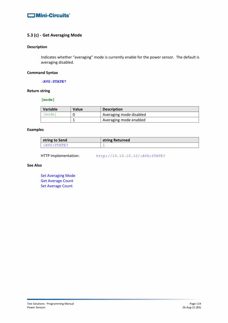
Test Solutions - Programming Manual Page 119 Power Sensors 26-Aug-21 (B3)
5.3 (c) - Get Averaging Mode
Description
Indicates whether “averaging” mode is currently enable for the power sensor. The default is averaging disabled.
Command Syntax
:AVG:STATE?
Return string
[mode]
Variable Value Description [mode] 0 Averaging mode disabled 1 Averaging mode enabled
Examples
string to Send string Returned :AVG:STATE? 1
HTTP Implementation: http://10.10.10.10/:AVG:STATE?
See Also Set Averaging Mode Get Average Count Set Average Count

Test Solutions - Programming Manual Page 120 Power Sensors 26-Aug-21 (B3)
5.3 (d) - Set Averaging Mode
Description
Enables or disables the power sensor “averaging” mode.
Command Syntax
:AVG:STATE:[mode]
Variable Value Description [mode] 0 Averaging mode disabled 1 Averaging mode enabled
Return string
[status]
Variable Value Description [status] 0 Command failed 1 Command completed successfully
Examples
string to Send string Returned :AVG:STATE:1 1
HTTP Implementation: http://10.10.10.10/:AVG:STATE:1
See Also Get Averaging Mode Get Average Count Set Average Count

Test Solutions - Programming Manual Page 121 Power Sensors 26-Aug-21 (B3)
5.3 (e) - Get Average Count
Description
Returns the number of power readings (from 1 to 32) over which the measurement will be averaged when averaging mode is enabled.
Command Syntax
:AVG:COUNT?
Return string
[count]
Variable Description
[count] The number of power readings over which to average the measurement
Examples
string to Send string Returned :AVG:COUNT? 3
HTTP Implementation: http://10.10.10.10/:AVG:COUNT?
See Also Get Averaging Mode Set Averaging Mode Set Average Count

Test Solutions - Programming Manual Page 122 Power Sensors 26-Aug-21 (B3)
5.3 (f) - Set Average Count
Description
Sets the number of power readings (from 1 to 32) over which to average the measurement when averaging mode is enabled. The default value is 1 (average the reading over 1 measurement).
Command Syntax
:AVG:COUNT:[count]
Variable Description
[count] The number of readings over which to average the power reading, from 1 to 32
Return string
[status]
Variable Value Description [status] 0 Command failed 1 Command completed successfully
Examples
string to Send string Returned :AVG:COUNT:10 1
HTTP Implementation: http://10.10.10.10/:AVG:COUNT:10
See Also Get Averaging Mode Set Averaging Mode Get Average Count

Test Solutions - Programming Manual Page 123 Power Sensors 26-Aug-21 (B3)
5.3 (g) - Get Compensation Frequency
Description
Returns the frequency currently in use for calibrating the input power measurements.
Command Syntax
:FREQ?
Return string
[freq]
Variable Description [freq] The current compensation frequency in MHz
Examples
string to Send string Returned :FREQ? 2500.000000 MHz
HTTP Implementation: http://10.10.10.10/:FREQ?
See Also Set Compensation Frequency Read Power

Test Solutions - Programming Manual Page 124 Power Sensors 26-Aug-21 (B3)
5.3 (h) - Set Compensation Frequency
Description
Sets the compensation frequency for calibrating input power measurements. This parameter must be set to ensure measurement accuracy. Note: This property will not filter out unwanted signals.
Command Syntax
:FREQ:[freq]
Variable Description [freq] The current compensation frequency in MHz
Return string
[status]
Variable Value Description [status] 0 Command failed 1 Command completed successfully
Examples
string to Send string Returned :FREQ:2500 1
HTTP Implementation: http://10.10.10.10/:FREQ:2500
See Also Get Compensation Frequency Read Power

Test Solutions - Programming Manual Page 125 Power Sensors 26-Aug-21 (B3)
5.3 (i) - Read Average Power
Description
Returns the input power measurement in dBm. The compensation frequency should be set prior to reading power in order to achieve the specified accuracy.
Command Syntax
:POWER?
Return string
[power]
Variable Description
[power] Input power measurement in dBm. Note: a power value of -99.000 dBm indicates that the input signal level is below the sensor's useable range.
Examples
string to Send string Returned :POWER? -22.050 dBm
HTTP Implementation: http://10.10.10.10/:POWER?
See Also Set Compensation Frequency Read Voltage

Test Solutions - Programming Manual Page 126 Power Sensors 26-Aug-21 (B3)
5.3 (j) - Read Voltage
Description
Returns the raw voltage detected at the power sensor head. There is no calibration for temperature or frequency.
Command Syntax
:VOLTAGE?
Return string
[volts]
Variable Description [volts] Input voltage reading in mV.
Examples
string to Send string Returned :VOLTAGE? 0.000105 Volt
HTTP Implementation: http://10.10.10.10/:VOLTAGE?
See Also Read Power

Test Solutions - Programming Manual Page 127 Power Sensors 26-Aug-21 (B3)
5.4 - SCPI - Peak & Average Power Sensor Measurement Functions These functions apply to Mini-Circuits’ PWR-xP Series peak & average power sensor models.
Description Command/Query
a Get Trigger Mode :TRIGGER:MODE?
b Set Trigger Mode :TRIGGER:MODE:[type]
c Get External Trigger Type :TRIGGER:EXTERNAL:[type]?
d Set External Trigger Type :TRIGGER:EXTERNAL:[type]
e Get Trigger Delay :TRIGGER:DELAY?
f Set Trigger Delay :TRIGGER:DELAY:[time]
g Get Trigger Output Mode :EXTOUT:SELECT?
h Set Trigger Output Mode :EXTOUT:SELECT:[type]
i Get Sample Time :SAMPLETIME?
j Set Sample Time :SAMPLETIME:[time]
k Get Compensation Frequency :FREQ?
l Set Compensation Frequency :FREQ:[freq]
m Read Peak & Average Power :POWER?
n Read Initial Power Array :POWER_ARRAY?
o Read Subsequent Power Arrays :POWER_ARRAY_EP[package]?

Test Solutions - Programming Manual Page 128 Power Sensors 26-Aug-21 (B3)
5.4 (a) - Get Trigger Mode
Description
Indicates the event which triggers the start of the power sensor’s sample period.
Applies To PWR-xP Series - Peak & average power sensors
Command Syntax :TRIGGER:MODE?
Return string
[type]
Variable Value Description [type] FREE Trigger not in use: Power sampling will start on request
INTERNAL Internal trigger in use: Power sampling will start on the rising edge of the first pulse detected at the RF input
EXTERNAL External trigger in use: Power sampling will start when an external trigger input signal is detected (see Get External Trigger Type)
Examples
string to Send string Returned :TRIGGER:MODE? FREE :TRIGGER:MODE? INTERNAL :TRIGGER:MODE? EXTERNAL
HTTP Implementation: http://10.10.10.10/:TRIGGER:MODE?
See Also Set Trigger Mode Get External Trigger Type Set External Trigger Type
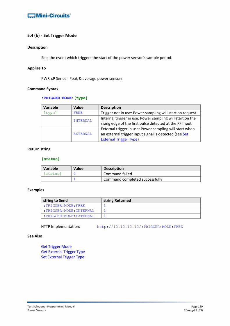
Test Solutions - Programming Manual Page 129 Power Sensors 26-Aug-21 (B3)
5.4 (b) - Set Trigger Mode
Description
Sets the event which triggers the start of the power sensor’s sample period.
Applies To PWR-xP Series - Peak & average power sensors
Command Syntax
:TRIGGER:MODE:[type]
Variable Value Description [type] FREE Trigger not in use: Power sampling will start on request
INTERNAL Internal trigger in use: Power sampling will start on the rising edge of the first pulse detected at the RF input
EXTERNAL External trigger in use: Power sampling will start when an external trigger input signal is detected (see Set External Trigger Type)
Return string
[status]
Variable Value Description [status] 0 Command failed 1 Command completed successfully
Examples
string to Send string Returned :TRIGGER:MODE:FREE 1 :TRIGGER:MODE:INTERNAL 1 :TRIGGER:MODE:EXTERNAL 1
HTTP Implementation: http://10.10.10.10/:TRIGGER:MODE:FREE
See Also
Get Trigger Mode Get External Trigger Type Set External Trigger Type

Test Solutions - Programming Manual Page 130 Power Sensors 26-Aug-21 (B3)
5.4 (c) - Get External Trigger Type
Description
Indicates whether power sampling will start on the rising or falling edge of an external trigger input signal when the power sensor is operating in external trigger mode.
Applies To PWR-xP Series - Peak & average power sensors
Command Syntax :TRIGGER:EXTERNAL:[type]?
Variable Value Description
[type] ONFALL Query whether power sampling is to start on the falling edge of an external trigger input signal
ONRISE Query whether power sampling is to start on the rising edge of an external trigger input signal
Return string
[status]
Variable Value Description [status] 0 The queried mode is not active 1 The queried mode is active
Examples
string to Send string Returned :TRIGGER:EXTERNAL:ONFALL? 0 :TRIGGER:EXTERNAL:ONRISE? 1
HTTP Implementation: http://10.10.10.10/:TRIGGER:EXTERNAL:ONFALL?
See Also Get Trigger Mode Set Trigger Mode Set External Trigger Type

Test Solutions - Programming Manual Page 131 Power Sensors 26-Aug-21 (B3)
5.4 (d) - Set External Trigger Type
Description
Sets whether power sampling will start on the rising or falling edge of an external trigger input signal when the power sensor is operating in external trigger mode.
Applies To PWR-xP Series - Peak & average power sensors
Command Syntax
:TRIGGER:EXTERNAL:[type]
Variable Value Description
[type] ONFALL Power sampling will start on the falling edge of an external trigger input signal
ONRISE Power sampling will start on the rising edge of an external trigger input signal
Return string
[status]
Variable Value Description [status] 0 Command failed 1 Command completed successfully
Examples
string to Send string Returned :TRIGGER:EXTERNAL:ONFALL 1 :TRIGGER:EXTERNAL:ONRISE 1
HTTP Implementation: http://10.10.10.10/:TRIGGER:EXTERNAL:ONFALL
See Also
Get Trigger Mode Set Trigger Mode Get External Trigger Type

Test Solutions - Programming Manual Page 132 Power Sensors 26-Aug-21 (B3)
5.4 (e) - Get Trigger Delay
Description
Indicates the delay to be applied between detection of an trigger signal and the start of power sampling.
Applies To PWR-xP Series - Peak & average power sensors
Command Syntax :TRIGGER:DELAY?
Return string
[time]
Variable Description
[time]
The delay time in microseconds (µS) to be applied between detection of an external trigger input signal and the start of power sampling
Examples
string to Send string Returned :TRIGGER:DELAY? 100
HTTP Implementation: http://10.10.10.10/:TRIGGER:DELAY?
See Also Set Trigger Delay

Test Solutions - Programming Manual Page 133 Power Sensors 26-Aug-21 (B3)
5.4 (f) - Set Trigger Delay
Description
Sets the delay to be applied between detection of a trigger signal and the start of power sampling.
Applies To PWR-xP Series - Peak & average power sensors
Command Syntax
:TRIGGER:DELAY:[time]
Variable Description
[time]
The delay time in microseconds (µS) to be applied between detection of an external trigger input signal and the start of power sampling
Return string
[status]
Variable Value Description [status] 0 Command failed 1 Command completed successfully
Examples
string to Send string Returned :TRIGGER:DELAY:0 1 :TRIGGER:DELAY:100 1
HTTP Implementation: http://10.10.10.10/:TRIGGER:DELAY:0
See Also
Get Trigger Delay

Test Solutions - Programming Manual Page 134 Power Sensors 26-Aug-21 (B3)
5.4 (g) - Get Trigger Output Mode
Description
Indicates whether the trigger output port is to be used as a TTL trigger signal (corresponding to the start of the sample period) or a video output (corresponding to the modulation of the RF input).
Applies To PWR-xP Series - Peak & average power sensors
Command Syntax :EXTOUT:SELECT?
Return string
[mode]
Variable Value Description
[mode] TRIG Trigger output port will provide a TTL signal at the start of the sampling period
VIDEO Trigger output port will provide a video signal corresponding to the modulation of the RF input
Examples
string to Send string Returned :EXTOUT:SELECT? TRIG : EXTOUT:SELECT? VIDEO
HTTP Implementation: http://10.10.10.10/:EXTOUT:TRIGGER?
See Also Set Trigger Output Mode

Test Solutions - Programming Manual Page 135 Power Sensors 26-Aug-21 (B3)
5.4 (h) - Set Trigger Output Mode
Description
Sets whether the trigger output port is to be used as a TTL trigger signal (corresponding to the start of the sample period) or a video output (corresponding to the modulation of the RF input).
Applies To PWR-xP Series - Peak & average power sensors
Command Syntax
:EXTOUT:SELECT:[mode]
Variable Value Description
[mode] TRIG Trigger output port will provide a TTL signal at the start of the sampling period
VIDEO Trigger output port will provide a video signal corresponding to the modulation of the RF input
Return string
[status]
Variable Value Description [status] 0 Command failed 1 Command completed successfully
Examples
string to Send string Returned :EXTOUT:SELECT:TRIG 1 :EXTOUT:SELECT:VIDEO 1
HTTP Implementation: http://10.10.10.10/:EXTOUT:SELECT:TRIG
See Also Get Trigger Output Mode

Test Solutions - Programming Manual Page 136 Power Sensors 26-Aug-21 (B3)
5.4 (i) - Get Sample Time
Description
Indicates the sample time to be captured by the power sensor measurements, from 10 µs to 1 s.
Applies To PWR-xP Series - Peak & average power sensors
Command Syntax :SAMPLETIME?
Return string
[time]
Variable Description
[time] The sample time in microseconds (µS) to be captured by the power sensor
Examples
string to Send string Returned SAMPLETIME? 10
HTTP Implementation: http://10.10.10.10/:SAMPLETIME?
See Also Set Sample Time

Test Solutions - Programming Manual Page 137 Power Sensors 26-Aug-21 (B3)
5.4 (j) - Set Sample Time
Description
Sets the sample time to be captured by the power sensor measurements, from 10 µs to 1 s.
Applies To PWR-xP Series - Peak & average power sensors
Command Syntax
:SAMPLETIME:[time]
Variable Description
[time] The sample time in microseconds (µS) to be captured by the power sensor
Return string
[status]
Variable Value Description [status] 0 Command failed 1 Command completed successfully
Examples
string to Send string Returned :SAMPLETIME:10 1 :SAMPLETIME:1000000 1
HTTP Implementation: http://10.10.10.10/:SAMPLETIME:10
See Also
Get Sample Time

Test Solutions - Programming Manual Page 138 Power Sensors 26-Aug-21 (B3)
5.4 (k) - Get Compensation Frequency
Description
Indicates the frequency currently set for calibrating the input power measurements.
Command Syntax
:FREQ?
Return string
[freq]
Variable Description [freq] The current compensation frequency in MHz
Examples
string to Send string Returned :FREQ? 2500.000000 MHz
HTTP Implementation: http://10.10.10.10/:FREQ?
See Also Set Compensation Frequency Read Peak & Average Power

Test Solutions - Programming Manual Page 139 Power Sensors 26-Aug-21 (B3)
5.4 (l) - Set Compensation Frequency
Description
Sets the compensation frequency for calibrating input power measurements. This parameter must be set to ensure measurement accuracy. Note: This property will not filter out unwanted signals.
Command Syntax
:FREQ:[freq]
Variable Description [freq] The current compensation frequency in MHz
Return string
[status]
Variable Value Description [status] 0 Command failed 1 Command completed successfully
Examples
string to Send string Returned :FREQ:2500 1
HTTP Implementation: http://10.10.10.10/:FREQ:2500
See Also Get Compensation Frequency Read Peak & Average Power

Test Solutions - Programming Manual Page 140 Power Sensors 26-Aug-21 (B3)
5.4 (m) - Read Peak & Average Power
Description
Returns the peak and average power measurement in dBm (separated by a space character) for the complete sample period of the sensor. The compensation frequency must be set prior to reading power in order to achieve the specified accuracy.
Command Syntax
:POWER?
Return string
[peak] [avg]
Variable Description
[peak] Peak power measured in dBm over the full sample period
[avg] Average power measurement in dBm over the full sample period
Examples
string to Send string Returned :POWER? -2.050 -25.250
HTTP Implementation: http://10.10.10.10/:POWER?
See Also Get Compensation Frequency Set Compensation Frequency Read Power Array
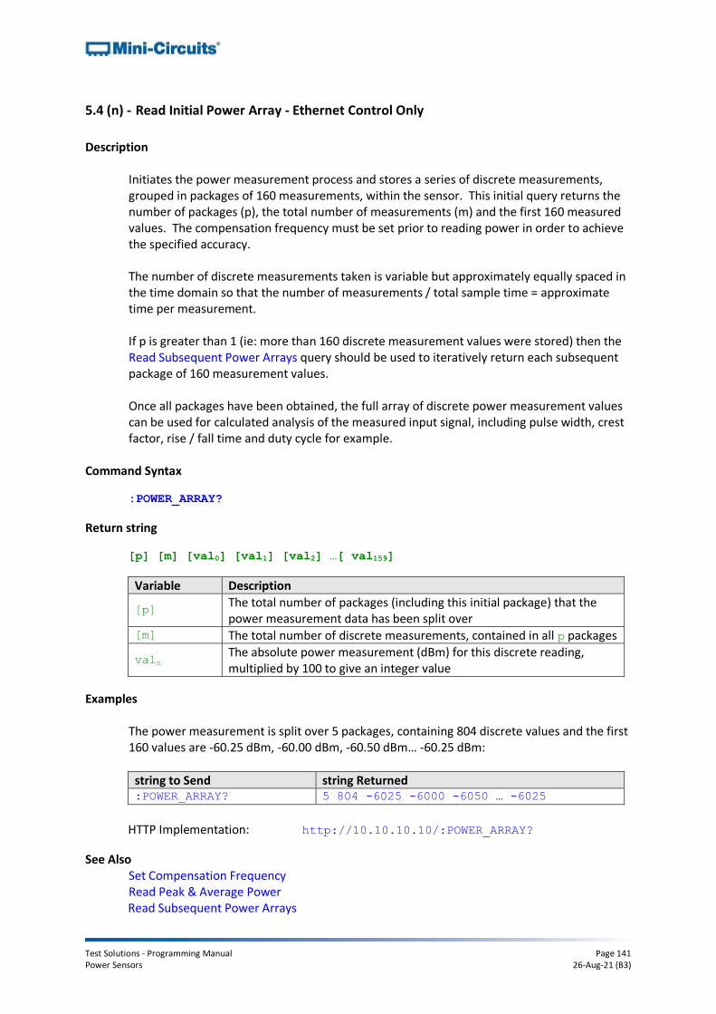
Test Solutions - Programming Manual Page 141 Power Sensors 26-Aug-21 (B3)
5.4 (n) - Read Initial Power Array - Ethernet Control Only
Description
Initiates the power measurement process and stores a series of discrete measurements, grouped in packages of 160 measurements, within the sensor. This initial query returns the number of packages (p), the total number of measurements (m) and the first 160 measured values. The compensation frequency must be set prior to reading power in order to achieve the specified accuracy. The number of discrete measurements taken is variable but approximately equally spaced in the time domain so that the number of measurements / total sample time = approximate time per measurement. If p is greater than 1 (ie: more than 160 discrete measurement values were stored) then the Read Subsequent Power Arrays query should be used to iteratively return each subsequent package of 160 measurement values. Once all packages have been obtained, the full array of discrete power measurement values can be used for calculated analysis of the measured input signal, including pulse width, crest factor, rise / fall time and duty cycle for example.
Command Syntax
:POWER_ARRAY?
Return string
[p] [m] [val0] [val1] [val2] …[ val159]
Variable Description
[p] The total number of packages (including this initial package) that the power measurement data has been split over
[m] The total number of discrete measurements, contained in all p packages
valn The absolute power measurement (dBm) for this discrete reading, multiplied by 100 to give an integer value
Examples
The power measurement is split over 5 packages, containing 804 discrete values and the first 160 values are -60.25 dBm, -60.00 dBm, -60.50 dBm… -60.25 dBm:
string to Send string Returned :POWER_ARRAY? 5 804 -6025 -6000 -6050 … -6025
HTTP Implementation: http://10.10.10.10/:POWER_ARRAY?
See Also Set Compensation Frequency Read Peak & Average Power Read Subsequent Power Arrays

Test Solutions - Programming Manual Page 142 Power Sensors 26-Aug-21 (B3)
5.4 (o) - Read Subsequent Power Arrays - Ethernet Control Only
Description
Follows on from Read Initial Power Array which initiates the power measurement process and stores a series of discrete measurements, grouped in packages of 160 measurements, within the sensor. The initial query returns the number of packages (p), the total number of measurements (m) and the first 160 measured values. If p is greater than 1 (ie: more than 160 discrete measurement values were stored) then this Read Subsequent Power Arrays query should be used to iteratively return each subsequent package of 160 measurement values. Once all packages have been obtained, the full array of discrete power measurement values can be used for calculated analysis of the measured input signal, including pulse width, crest factor, rise / fall time and duty cycle for example.
Command Syntax
:POWER_ARRAY_EP[n]?
Variable Description
[n] The package index from 1 to m. The total number of packets (m) and the initial package (with index 0) is returned by the Read Initial Power Array query.
Return string
[val_0] [val_1] [val_2] …[val_159]
Variable Description
[val_n] The absolute power measurement (dBm) for this discrete reading, multiplied by 100 to give an integer value
Examples
Read Initial Power Array indicated that the power measurement is split over 5 packages, containing 804 discrete values, and returned the first 160 values (package 0). The remaining 4 packages of data must therefore be requested. Packages 1 to 3 contain 160 data points each and the final package contains the final 4 data points.
string to Send string Returned :POWER_ARRAY? 5 804 -6025 -6000 -5975 … -5025 :POWER_ARRAY_EP1? -5050 -5075 -5075 … -6000
:POWER_ARRAY_EP2? -6025 -6000 -5975 … -5025
:POWER_ARRAY_EP3? -5050 -5075 -5075 … -6000
:POWER_ARRAY_EP4? -6025 -6050 -6075 -6075
See Also Read Peak & Average Power Read Initial Power Array