
MINERVA_MZX_125-250_User_Manual.pdf
65
MINERVA MZX 125/250 ADDRESSABLE FIRE DETECTION SYSTEMS USER MANUAL V1.0/13/11/08
-
Upload
mohsen-zeyad1 -
Category
Documents
-
view
153 -
download
51
Transcript of MINERVA_MZX_125-250_User_Manual.pdf

MINERVA MZX 125/250ADDRESSABLE FIREDETECTION SYSTEMS
USER MANUAL
V1.0/13/11/08

NOTICE
All rights reserved. Reproduction of any part of this manual in any form whatsoever without Thorn Security’s express written permission is forbidden.
The contents of this manual are subject to change without notice.
All effort has been made to ensure that the accuracy of this manual.
However, should any errors be detected, Thorn Security would greatly appreciate being informed of them.
The above not withstanding, Thorn Security can assume no resposibility for any errors in this manual or their consequences.
For further information, see Tyco Safety Product’s web site at:
www.tycoemea.com

MZX 125/250 Fire Detection Systems
Content
1 Guide to this manual ............................................ 6
2 Introduction .......................................................... 62.1 Key function and features ............................................................................ 6
3 Operating Instructions....................................... 103.1 Operator’s indicators and controls ............................................................103.1.1 General ....................................................................................................................................... 103.1.2 Display control module .......................................................................................................... 103.1.3 Indicators ................................................................................................................................... 143.1.4 Switches..................................................................................................................................... 14
3.2 LCD display...................................................................................................153.2.1 Fire window............................................................................................................................... 153.2.2 Status window.......................................................................................................................... 163.2.3 Main window ............................................................................................................................ 163.2.4 Softkey window ....................................................................................................................... 16
3.3 Normal operation .........................................................................................163.3.1 Event monitoring ..................................................................................................................... 173.3.2 Event display ............................................................................................................................. 17
3.4 Operation in alarm .......................................................................................183.4.1 System response ..................................................................................................................... 183.4.2 Sounder silencing .................................................................................................................... 193.4.3 Resetting the controller.......................................................................................................... 203.4.4 Multiple events......................................................................................................................... 203.4.5 Pre-alarm warning ................................................................................................................... 21
3.5 Operation in fault condition........................................................................213.5.1 System response ..................................................................................................................... 213.5.2 Operator action ........................................................................................................................ 21
3.6 Fire control keys ..........................................................................................223.6.1 Evacuate..................................................................................................................................... 233.6.2 Day/night mode....................................................................................................................... 233.6.3 Investigate delay ...................................................................................................................... 233.6.4 Test .............................................................................................................................................. 24
3.7 Auxiliary display devices ............................................................................243.7.1 General ....................................................................................................................................... 243.7.2 Repeaters................................................................................................................................... 243.7.3 Printers ....................................................................................................................................... 243.7.4 LCD repeaters ........................................................................................................................... 24
3 Doc version 1

MZX 125/250 Fire Detection Systems
4 Controller Functions...........................................254.1 Access levels ............................................................................................... 254.1.1 General ....................................................................................................................................... 25
4.2 Entering passcodes..................................................................................... 26
4.3 Valid values.................................................................................................. 26
4.4 Main menu.................................................................................................... 27
4.5 Accept events.............................................................................................. 28
4.6 View status .................................................................................................. 28
4.7 Isolate/de-isolate ........................................................................................ 31
4.8 Time/date..................................................................................................... 344.8.1 Set time/date ........................................................................................................................... 344.8.2 Summer/winter....................................................................................................................... 35
4.9 Event log....................................................................................................... 354.9.1 View event log.......................................................................................................................... 364.9.2 Print event log .......................................................................................................................... 364.9.3 Filter ............................................................................................................................................ 37
4.10 View/print status......................................................................................... 384.10.1 View/print point isolated....................................................................................................... 384.10.2 View/print points untested/failed ...................................................................................... 394.10.3 View/print point values ......................................................................................................... 404.10.4 View faults................................................................................................................................. 414.10.5 View loop point counters....................................................................................................... 414.10.6 Active points ............................................................................................................................. 444.10.7 By function ................................................................................................................................ 45
4.11 Service.......................................................................................................... 474.11.1 Walk test .................................................................................................................................... 474.11.2 Maintenance............................................................................................................................. 524.11.3 Configuration............................................................................................................................ 55
5 Routine checks ...................................................635.1 General ......................................................................................................... 63
5.2 Daily checks................................................................................................. 63
5.3 Weekly checks ............................................................................................ 63
4 Doc version 1

MZX125/250 Manual Guide
Doc. version 1 5
1 Guide to this manual
In this documentation keywords and symbols denote warnings, info or instructions (see table 1).
Keyword Symbol Explanation
DANGER Warning.
Imminent danger.
Death or severe injury when disregarded.
WARNING Warning.
Potentially dangerous situation.
Death or severe injury possible when disregarded.
CAUTION Warning.
Potentially dangerous situation.
Minor injury or material damage possible when disregarded.
Helpful information.
Tab. 1: Keywords and symbols in this documentation

MZX 125/250 Fire Detection Systems
Fig.. 1: MZX125
6 Doc. version 1

MZX125/250 Fire Detection Systems
Fig.. 2: MZX250
Doc. version 1 7

MZX 125/250 Fire Detection Systems
2 INTRODUCTION
The instructions given in this document are common to all the ‘MZX125 and MZX250’ fire controllers, any differences being outlined as appropriate This document is written for Firmware Version 14.
The MINERVA MZX 125/250, form a comprehensive and compatible range of modular and flexible EN54 approved addressable fire controllers using Tyco MZX TechnologyTM.
Both variants fully comply with the requirements of EN54 parts 2 and 4 and may be installed in a system which complies with the requirements of BS 5839 : Part 1.
2.1 KEY FUNCTIONS AND FEATURES
The MZX controllers are built around common hardware and software modules incorporating the following common functions and features:
Full EN54 compliant control switches and indicators with keyswitch enable and optional programmable LED indicators and control switches.
Large backlit 16 line x 40 character LCD display with detailed and precise identification of all sectors, zones and points, comprehensive 95 character emergency procedure instructions and full system status indication including counters of number of points in alarm, fault, disabled and test mode.
Extensive menu driven and password controlled operator and engineer functions including extensive isolate, override, test, service and diagnostic functions.
System manager and engineer functions including editing of point descriptions and viewing/printing of point values including CO levels, temperatures and detector obscuration levels.
Optional self-test and verification of detectors from the controller.
Peer-to-peer communication with up to 98 other controllers providing a seamless operator interface to all other relevant defined controllers on the network.
Event log for logging of up to 3000 events which can be viewed, selected and printed.
Constant monitoring of all detectors and input circuits and processing of detector sensor information using standard, CCO and FastLogic fuzzy logic algorithms.
Long term averaging and condition monitoring of smoke detectors with dirty detector identification.
Automatic or manual switching of detector modes and sensitivities according to changes in occupancy patterns (day mode) and variations in fire risk.
8 Doc. version 1

MZX125/250 Fire Detection Systems
Constant fault monitoring of all hardware components, power supplies, batteries, relays, sounder and speaker circuits, addressable loops, detectors and addressable devices, monitored input circuits, remote and local communication links.
Communication with up to 125 addresses on one detection loop (MZX125) or 250 addresses on one detection loops (MZX250) per controller and a combination of up to 1500 auxiliary I/O, controller plus 7 full function repeaters and multiple remote printers.
Signalling, supervision, status and fault indication of central station alarm signalling equipment such as BT Redcare STU.
Option for one repeater to be provided from a remote PC computer using MX-Remote service and diagnostics software over the public switched telephone network (PSTN).
Default cause and effect providing computer control of all outputs, sounders, beacons and speakers in the event of alarm conditions.
Powerful programmable cause and effect using the flexible and easily configured MINERVA group based event/action programming language.
Synchronisation and multiple output pulse patterns for phased evacuation of up to 16 zones (MZX125) or 32 zones (MZX250) using “Bell Mapping”.
Powerful programmable cause and effect using the flexible and easily configured MINERVA group based event/action programming language.
Doc. version 1 9

MZX 125/250 Fire Detection Systems
3 OPERATING INSTRUCTIONS
3.1 OPERATOR’S INDICATORS AND CONTROLS
3.1.1 GENERAL
ALL operator controls and indicators are mounted on the front panel.
3.1.2 DISPLAY CONTROL MODULE
The Display Control Module (Fig. 3 MZX125 and Fig. 4 MZX250) contain the following indicators and controls:
A 640 character backlit LCD alphanumeric display, arranged in 16 rows of 40 characters. This is used to display information about the system status and alarms. The backlight is on when the keyswitch is set to the ‘enable’ position, when a key is pressed or when an Alarm or Fault is present.
Switches F1 to F5 - used to carry out the functions displayed on the bottom line of the LCD display.
An alphanumeric keypad used for entering access codes, text strings or general information as follows:
10 Doc. version 1

MZX125/250 Fire Detection Systems
SCROLL UP and SCROLL DOWN keys - used to scroll through a display or log one entry at a time. These keys will auto-repeat if held down, ie, will scroll continuously.
When used in conjunction with the Configuration menu, the UP key switches to upper case and the DOWN key to lower case.
7PQRS
8TUV
9WXYZ
6MNO
5JKL
4GHI
3DEF
2ABC
0
1
Used to enter the number 0
Used to enter the number 1 or special symbols
Used to enter the number 2 or letters ‘A’, ‘B’ or ‘C’
Used to enter the number 3 or letters ‘D’, ‘E’ or ‘F’
Used to enter the number 4 or letters ‘G’, ‘H’ or ‘I’
Used to enter the number 5 or letters ‘J’, ‘K’ or ‘L’
Used to enter the number 6 or letters ‘M’, ‘N’ or ‘O’
Used to enter the number 7 or letters ‘P’, ‘Q’, ‘R’ or ‘S’
Used to enter the number 8 or letters ‘T’, ‘U’ or ‘V’
Used to enter the number 9 or letters ‘W’, ‘X’, ‘Y’ or ‘Z’
Doc. version 1 11

MZX 125/250 Fire Detection Systems
1 2 3 4 5 6 7 8
9 10 11 12 13 14 15 16
F1F2
F3F4
F5SI
LENC
EBU
ZZER
SILE
NCE
RESO
UND
RESE
TDA
YNI
GHT
DELA
YIN
VEST
IGAT
EEV
ACUA
TE
PR
OTE
CTI
ON
SIG
NA
LLIN
GS
OU
ND
ER
SPA
NE
LG
EN
ER
AL
AC
TIVA
TED
FAU
LT
DIS
AB
LED
AC
TIVA
TED
FAU
LT
DIS
AB
LED
AC
TIVA
TED
FAU
LT
DIS
AB
LED
PO
WE
R O
N
MA
INS
FA
ULT
SY
STE
M F
AU
LT
DAY
MO
DE
FIR
E
FAU
LT
DIS
AB
LED
TES
T
1 *A
BC2
3 DE
F
45
6G
HI
JKL
MN
O
78
9P
QR
STU
VW
XY
Z
0
01
Fig.. 3: MZX125 Display Control Module
12 Doc. version 1

MZX125/250 Fire Detection Systems
F1 F2 F3 F4 F5
1* ABC
2 3
4 5 6
7 8 9
0
DEF
GHI JKL MNO
PQRS TUV WXYZ
SILENCEBUZZER
SILENCERESOUND RESET DAY
NIGHT DELAYINVESTIGATE EVACUATE
PROTECTIONSIGNALLINGSOUNDERSPANELGENERALACTIVATED
FAULT
DISABLED
ACTIVATED
FAULT
DISABLED
ACTIVATED
FAULT
DISABLED
POWER ON
MAINS FAULT
SYSTEM FAULT
DAY MODE
FIRE
FAULT
DISABLED
TEST
1
2
3
4
5
6
7
8
9
10
11
12
13
14
15
16
17
18
19
20
21
22
23
24
25
26
27
28
29
30
31
32
ZONE DISPLAY
0 1
Fig.. 4: MZX250 Display Control Module
Doc. version 1 13

MZX 125/250 Fire Detection Systems
3.1.3 CONTROL CONTROL MODULE
The Display Control Module contains the following indicators and controls:
INDICATORS
GENERAL
A red Fire LED.A yellow Fault LED.A yellow Disabled LED.A yellow Test LED.
PANEL
A green Power ON LED.A yellow LED to indicate Mains Fault.A yellow LED to indicate System Fault.A yellow LED to indicate Day Mode.
SOUNDER
A red Activated LED.A yellow Fault LED.A yellow Disabled LED.
SIGNALLING
A red Activated LED.A yellow Fault LED.A yellow Disabled LED.
PROTECTION
A red Activated LED.A yellow Fault LED.A yellow Disabled LED.
ZONES
One red (Fire) and one yellow (Fault) LED per zone .
SWITCHES
‘ENABLE’ keyswitch - a two position keyswitch, with positions ‘normal’ and ‘enable’.
Seven control switches:
‘SILENCE BUZZER’ - used to silence the internal buzzer.
‘SILENCE/RESOUND’ - used to silence/resound external sounders.
‘RESET’ - used to reset the system after an alarm or event has occurred.
14 Doc. version 1

MZX125/250 Fire Detection Systems
‘DAY MODE’ - used to set the system into the daytime operation mode.
‘INVESTIGATE DELAY’ - is used to end signalling delay time and start the investigation time.
‘SPARE’ - is configurable to customer requirements.
‘EVACUATE’ - is used to activate external sounders.
3.2 LCD DISPLAY
The LCD display is divided into four windows as shown in Fig. 5:
Fire19 characters x 8 lines
Main 19 characters x 14 lines
Status 19 characters x 5 lines
Softkeys F1, F2, F4 and F5 - 7 characters, F3 - 8 characters
3.2.1 FIRE WINDOW
The fire window in the quiescent mode will display the product name, date/time and company name.
On detection of an Alarm condition, the fire window will display ‘First Fire’ and associated information. For multiple alarms in the system the fire window will display the first and last alarms.
The number of alarms is displayed at the right hand side of line 5 in the fire window.
1234567890123456789 1234567890123456789123 Main4 Window5678901234
123 Fire4 Window5678
12 Status3 Window45
S'key 1 S'key 2 S'key 3 S'key 4 S'key 5
Fig.. 5:
Doc. version 1 15

MZX 125/250 Fire Detection Systems
3.2.2 STATUS WINDOW
The status window displays the number of faults, isolates etc.
3.2.3 MAIN WINDOW
The main window displays logs, information text, menus and device identification.
3.2.4 SOFTKEY WINDOW
The softkey windows change dependant on the option selected.
3.3 NORMAL OPERATION
When the controller is initially powered up, with no faults or alarms in thesystem and the ‘Enable’ key in the ‘off’ position, the following screen isdisplayed:
First FireZone 002 B0011st Floor CorridoorRoom 117Last Fire 002Zone 030 B055 4th Floor Washroom / Window
MX Panel
Fri, 17-Mar-08 11:57
Company Name
General
LED Tst LightNot Clr
16 Doc. version 1

MZX125/250 Fire Detection Systems
3.3.1 EVENT MONITORING
The term ‘event’ is used to describe a change in system status that must be acknowledged and/or generates an output.
Examples of events include:
Mains failure
Detection of a fire condition
Operation of ‘EVACUATE’ key
All events trigger a response, the category of which depends on the event type and will be one of the following (in priority order):
Full Alarm or Alert
Pre-Alarm
Fault
Isolation
Test Mode
Warning
Information
When an event occurs, it is stored in the event log. The contents of this log may be displayed in two formats:
Unaccepted and locally accepted events
All events in chronological order of occurrence
The events are stored in chronological order with unaccepted events marked as outstanding. The event log may hold up to 3000 events; in the unlikely occurrence of the log filling up, the oldest record will be overwritten.
3.3.2 EVENT DISPLAY
The display automatically shows the last event of the category with the highest priority. With Scroll keys, it is possible to get all events in this category in chronological order. With Softkey F5 the user can change to another category (if available).
Important: Category ‘Full Alarm/Alert’ shows only the first point of a zone in alarm. If two points of one zone are in alarm, only the first one which was in alarm will be displayed. The second alarm can only be accessed via the menu option ‘View Event Log’.
Doc. version 1 17

MZX 125/250 Fire Detection Systems
3.4 OPERATION IN ALARM
3.4.1 SYSTEM RESPONSE
When a fire condition is detected, the system responds as follows:
1 The internal buzzer will sound in a continuous tone.
2 The red ‘FIRE’ LED will light.
3 The SOUNDERS and NOTIFICATION STATUS ‘ACTIVATED’ red LEDs will light.
If the alarm is initiated by a detector, there may be a delay of from 1 to 10 minutes before the NOTIFICATION STATUS ‘ACTIVATED’ led lights. This is to allow time for the alarm to be investigated and any relevant action taken before signalling is initiated. A Callpoint set to evacuate will initiate signalling immediately. Refer to Section 2.6.3.
4 For the MZX controllers, the sounders and any other configured outputs will be activated.
5 The LCD will display a message in the format:
The message format is as follows:
Under ‘FIRE’:
The top line shows the Zone and Point number of thedevice in alarm.
The second line shows the zone description (defined atconfiguration).
The third line shows the point description (defined atconfiguration).
The fourth line shows the type of alarm.
If no information text is shown:
First FireZone 002 B0021st Floor CorridoorRoom 117
General
Menu
First Fire
Passcode More
001
Information
18 Doc. version 1

MZX125/250 Fire Detection Systems
The fifth line shows date and time.The sixth line shows the device type.
The seventh line shows the actual CURRENTtemperature (if heat sensor).
The above is only displayed if Extended Alarm Information has been selected at configuration.
Under ‘First Fire’:
The first three lines from ‘FIRE’ are repeated.The number of alarms is displayed on the black bar underneath the first fire information.
3.4.2 SOUNDER SILENCING
When a FIRE ALARM is received, investigate the cause of the alarm.
WARNING:
WHEN SEARCHING AN AREA FOR THE SOURCE OF A FIRE ALARM SIGNAL, WHERE A FIRE ALARM HAS BEEN INITIATED BY A ‘CARBON MONOXIDE’ FIRE DETECTOR, IT
MUST BE REMEMBERED THAT A CARBON MONOXIDE FIRE DETECTOR MAY GENERATE AN ALARM BEFORE
OTHER FIRE INDICATORS (SUCH AS SMOKE) ARE PRESENT.
THIS OCCURS MOST NOTABLY IN DEEP SEATED FIRES IN DENSELY PACKED MATERIALS, AREAS WHERE FIRES
MAY OCCUR IN CUPBOARDS AND STOREROOMS REMOTE FROM DETECTORS AND WHERE SMOKE
IMPERVIOUS BARRIERS EXIST BETWEEN THE SEAT OF THE FIRE AND THE DETECTOR (SUCH AS WITHIN WALL CAVITIES). THESE FACTORS SHOULD BE CONSIDERED
CAREFULLY BEFORE DECLARING SAFE ANY AREA WHERE A CARBON MONOXIDE FIRE DETECTOR HAS
RAISED AN ALARM.
Once the cause of the alarm has been determined and all appropriate action has been taken, silence the sounders as follows:
1 Insert the key into the front panel keyswitch and turn it clockwise to the ‘enable’ position.
2 Press ‘SILENCE/RESOUND’.
Doc. version 1 19

MZX 125/250 Fire Detection Systems
The system will respond as follows:
1 The sounders will be silenced.
2 The ‘SOUNDER ACTIVATED’ LED will extinguish.
3 All other outputs will remain activated.
4 The LCD display will remain showing the type of alarm and the full zone identification. The ‘GENERAL’ display window will show ‘Sounder SIL’.
If it is required to manually resound the sounders, pressing the ‘SILENCE/RESOUND’ key will reactivate the sounders.
3.4.3 RESETTING THE CONTROLLER
When the system is in a Fire Alarm state, Silence must be operated before Reset is possible. This interlock is always present under Fire Alarm condition, even if all sounders are isolated.
The controller should also NOT be reset until the source of the alarm has been determined by the Fire Brigade or the cause otherwise found (and the condition removed).
Once the notes above have been observed, press the ‘RESET’ key. The display will show the following message:
Reset
in
Progress...
*
After 17 to 20 seconds, the LCD will return to the normal display (Section 2.3) if no faults or other events are present.
3.4.4 MULTIPLE EVENTS
If, when in alarm condition, a second alarm (of another zone) is received, the system response is dependent on the nature and source of the second alarm as follows:
1 If the sounders have NOT been silenced, the following will occur:
2 The internal buzzer will continue to sound without interruption.
3 The LCD will continue to display the alarm message for the FIRST fire alarm and also the last fire alarm.
4 The alarm count will be incremented.
20 Doc. version 1

MZX125/250 Fire Detection Systems
3.4.5 PRE-ALARM WARNINGS
If the LCD shows a message including a “warning” indication, a pre-alarm condition has been detected by the controller. This may be indicated for example, if a detector identifies a build-up of smoke or heat that might result from a fire, but the alarm threshold has not yet been reached. The internal buzzer will sound but the sounders and visual fire indicators will remain inactive at this stage. Proceed as follows:
1 Accept the event, (if the option is available), noting the location of the event.
2 Initiate action to deal with the condition indicated, taking care to determine if the warning was initiated by a fire condition or by a system fault.
If the detector subsequently shows an alarm condition, an alarm will be generated, regardless of whether the pre-alarm warning was accepted.
3.5 OPERATION IN FAULT CONDITION
3.5.1 SYSTEM RESPONSE
When a Fault condition is detected, the system will respond as follows:
1 The internal buzzer will pulse.
2 The yellow ‘GENERAL FAULT’ LED will light.
3 The LCD backlight will come on and will display the following type of screen:
The message format is as follows:
The top line shows the Zone and point number in fault condition.
The second line shows the zone description (defined in configuration).
Zone 000 R10System ZoneBattery Fault IP
BATTERY FAULT
17-Mar-00 15:00:00Digital Input
MX Panel
Fri, 17-Mar-08 15:00
Company Name
Flt P 002
General
LED Tst
FAULT
Info MoreNot Clr
Doc. version 1 21

MZX 125/250 Fire Detection Systems
The third line shows the point description (defined in configuration).
The fourth line shows the type of fault.
If no information text is shown:
The fifth line shows the date and time.
the sixth line shows the device type.
The message will continue to be displayed until the intervention of an operator or the fault is cleared.
3.5.2 OPERATOR ACTION
When a Fault condition occurs, proceed as follows:
1 Press the ‘SILENCE BUZZER’ key.The internal buzzer will silence, but the LED and display will continue to operate as described.
2 Investigate the source of the fault and where possible remove.
If the fault cannot be cured, contact your local supplier and arrange for a service visit.
The fault information will be displayed until the fault is cleared.
3.6 FIRE CONTROL KEYS
There are six fire control keys on the Display Control Module, namely:
SILENCE BUZZER
SILENCE/RESOUND
RESET
DAY MODE
INVESTIGATE DELAY
EVACUATE
Only the ‘SILENCE BUZZER’ key is active without the ‘Enable’ key being inserted and turned to the ‘Enabled’ position.
The functions of ‘SILENCE BUZZER’, SILENCE/RESOUND’ and ‘RESET have already been described. The functions of ‘EVACUATE or FIRE ALARM’, ‘INVESTIGATE DELAY’ and ‘DAY MODE’ are described in the following paragraphs.
22 Doc. version 1

MZX125/250 Fire Detection Systems
3.6.1 EVACUATE
Once enabled by the keyswitch, pressing ‘EVACUATE’ will cause the following:
1 The internal buzzer will sound continuously.
2 The red ‘FIRE’ LEDs will light.
3 The sounders and any other configured outputs are activated.
4 The LCD will display the following type of screen:
3.6.2 DAY/NIGHT MODE
In night mode the system activates immediately when an alarm is received, the internal buzzer, all sounders and alarm signalling outputs operate.
In day mode, on receipt of an alarm, only the internal buzzer and sounders are activated immediately. A delay time is started (default 60 seconds) in which the alarm message must be acknowledged (‘Investigate delay’ switch) to start the investigation time. If there is no acknowledgement within this time, the alarm signalling outputs will be activated.
The investigation time (default 10 minutes) is the time remaining for staff to carry out investigation of the alarm source, before the alarm signalling outputs will be activated.
An evacuate callpoint will initiate an immediate alarm.
Signalling is always immediate if sounder faults exist in the system.
3.6.3 INVESTIGATE DELAY
The ‘INVESTIGATE DELAY’ switch is only active when the controller is in the ‘DAY MODE’ of operation. If a Fire Alert is received at the controller, the signalling output is delayed for 1 minute, if the ‘Investigate Delay’ switch is pressed during this period a further delay (configurable between 1 and 10 minutes) is initiated. This delay allows for the alarm to be investigated, if it is a false alarm, the cause of the alarm can be removed and the controller to be silenced and reset. If the alarm is real, then pressing the ‘EVACUATE/FIRE ALARM, switch will cause the signalling output to activate.
First FireZone 000 RB002R12System ZoneEvacuate Button
General
Menu
F I R EFirst Fire
Information
Not Available
Info Passcode More
001
Not Clr
Doc. version 1 23

MZX 125/250 Fire Detection Systems
3.6.4 TEST
Pressing ‘LED TEST’ causes all the LEDs and internal buzzer to operate for a few seconds. If the system includes a repeater panel, only the panel that is operated is activated.
3.7 AUXILIARY DISPLAY DEVICES
3.7.1 GENERAL
Depending on the configuration of the system, there may be one or more auxiliary display devices fitted. These devices may be of the following types:
Repeaters
Printers
The functions of and operating instructions for these devices are given in the following paragraphs.
3.7.2 REPEATERS
A repeater allows the controller to be operated from a remote location and provides remote indications of the state of the controller. The front panel of the repeater is identical to that of the controller (see Fig. 1) and all controller operations may be performed at the repeater panel.
3.7.3 PRINTERS
Refer to the manual supplied with the printer for operating instructions.
3.7.4 LCD REPEATERS
LCD Repeaters can:
Display the alarm and fault messages as displayed on the Controller on a backlit 4 x 20-character alphanumeric display.
Provide an internal log for up to 150 events.
Provide an internal audible warning of an event.
Allow the event log to be displayed using the scroll keys.
Silence the internal buzzer and external sounder (if fitted) with the key.MUTE
24 Doc. version 1

MZX125/250 Fire Detection Systems
4 CONTROLLER FUNCTIONS
As stated, the MZX controller has built-in functions. These functions allow the operator to perform such actions as viewing the event log, setting the date and time, etc. The functions are arranged according to sophistication and access to certain of them necessarily needs to be restricted to trained staff.
The control of access has been achieved by assigning functions to Access Levels, each Access Level having an associated numeric passcode. The passcode for a particular Access Level is defined at system configuration.
4.1 ACCESS LEVELS
4.1.1 GENERAL
The access levels available are as follows:
Customer Operator 1 to 7 - 4 digits
Customer Manager 1 - 5 digits
Customer Manager 2 - 6 digits
These access levels are described in the following paragraphs. A maximum of 99 Passcodes are available which may be split between Access Levels as required.
The Customer Operator 1 Access Level is achieved by turning the ‘ENABLE’ key to the enable position (ie, a Passcode is not required).
Table 1 contains Access Levels and Menu Options available at each level.
Doc. version 1 25

MZX 125/250 Fire Detection Systems
4.2 ENTERING PASSCODES
In order to avoid repetition, however, the general procedure for entering a PASSCODE is described as follows:
1 Turn the ‘ENABLE’ key to the ON position, press F3 (Passcode), enter your ID (press F5 ‘Enter’ if the ID has only one digit).
4.3 VALID VALUES
The following are values which may be entered for each option:
EnableKey
PageNo.Customer Operator
CustomerManager
1 2 3 4 5 6 7 1 2Lamp/Buzzer/LCD Test ✔ ✔ ✔ ✔ ✔ ✔ ✔ ✔ ✔ OFFUnrestored Events ✔ ✔ ✔ ✔ ✔ ✔ ✔ ✔ ✔ OFFInformation Text ✔ ✔ ✔ ✔ ✔ ✔ ✔ ✔ ✔ OFFView Events (Scrolling) ✔ ✔ ✔ ✔ ✔ ✔ ✔ ✔ ✔ OFF
MAIN MENU ✔ ✔ ✔ ✔ ✔ ✔ ✔ ✔ ✔ ON 18
Accept Events ✔ ✔ ✔ ✔ ✔ ✔ ✔ ✔ ON 18
View Status ✔ ✔ ✔ ✔ ✔ ✔ ✔ ✔ ✔ ON 18
Isolate/De-Isolate ✔ ✔ ✔ ✔ ON 20
Time/Date ✔ ✔ ✔ ✔ ✔ ON 21Set time/Date ✔ ✔ ✔ ✔ ✔ ON 21Summer/Winter ✔ ✔ ✔ ✔ ✔ ON 21
Event log ✔ ✔ ✔ ✔ ✔ ✔ ✔ ON 21View Event Log ✔ ✔ ✔ ✔ ✔ ✔ ✔ ON 22Print Event Log ✔ ✔ ✔ ✔ ✔ ✔ ✔ ON 22Filter ✔ ✔ ✔ ✔ ✔ ✔ ✔ ON 22
View/print status ✔ ✔ ✔ ✔ ✔ ✔ ON 23Points Isolated ✔ ✔ ✔ ✔ ✔ ✔ ON 23Points Untested/Failed ✔ ✔ ✔ ✔ ✔ ✔ ON 23Point Values ✔ ✔ ✔ ✔ ✔ ✔ ON 23View Faults ✔ ✔ ✔ ✔ ✔ ✔ ✔ ON 24Loop Point Counter ✔ ON 24Active Points ✔ ✔ ✔ ONBy Function ✔ ✔ ✔ ON
Service ✔ ✔ ✔ ON 25Walk Test ✔ ✔ ✔ ON 26Maintenance engineer ✔ ✔ ON 28
Fire Alarm Cycle Count ✔ ✔ ON 28Maintenance Request ✔ ✔ ON 28Battery Test ✔ ✔ ON 28Project Numbers ✔ ON 29Software Versions ✔ ON 29Menu Points ✔ ON 29
Configuration ✔ ✔ ON 29Change Text ✔ ✔ ON 30
Table. 1 Menu Options and Access Levels
Panel Number 1 - 99Zone Number 1 -
240*Sector Number 1 - 240RBus Number 0 - 15
26 Doc. version 1

MZX125/250 Fire Detection Systems
‘*’ depending on the configuration 40/80/120/160/200 or 240 zones.
4.4 MAIN MENU
When the system is in quiescent mode (ie, displaying the date and time), entering a passcode affords the user access to the main menu. The structure of this menu is shown below.
The menu shown is for Customer Manager 2 level. Only the options appropriate to the access level entered will be displayed.
Each of the options available leads to further menus or functions, which are described in the following paragraphs.
Real PointPseudo PointXBus Point
1 - 241 - 81 - 96
Local I/OReal PointPseudo PointIOBus pointTimer PointUser Point
1 - 181 - 421 - 241 - 101 - 10
1 - Accept Events2 - View Status3 - Isolate/De-Isol4 - Time / Date5 - Event Log6 - View/Print Data7 - Service8 - Configuration9 - Test Buzzer, LEDs & Display
Alarm Count: 0021
MX Panel
Thu, 26-Jul-07 00:01
Company Name
General
Back
Main menu
Doc. version 1 27

MZX 125/250 Fire Detection Systems
4.5 ACCEPT EVENTS
Allows displayed events to be accepted. Press 1 from the main menu, the following type of screen will be displayed:
Use the F4 Key ‘<<’ and F5 key ‘>>’ keys to move between events. Usr F3 ‘Accept’ to accept an event.
4.6 VIEW STATUS
Allows the status of all points and zones on the system to be viewed. Press 2 from the Main menu, the following type of screen will be displayed:
Point - allows the status of any points on the system (both inputs and outputs) to be checked.
Point I/P only - allows the status of only input devices to be checked (eg, detectors).
Point O/P only- allows the status of only output devices to be checked (eg, sounders, functional bases, etc.).
Zone - allows the total status of all points in a specified zone to be checked.
Zone 000 R10System ZoneBattery Fault IP
BATTERY FAULT
01-Mar-00 14:15:02Digital Input
SYSTEM
Thu, 26-Jul-07 14:15
Company Name
Fault 02
General
Back
Accept Events
1000Accept >><<
1 - Point2 - Point I/P only3 - Point O/P only4 - Zone5 - Zone Maps
MX Panel
Wed, 01-Mar-08 14:15
Company Name
General
Back
View Status
28 Doc. version 1
MZX125/250 Fire Detection Systems
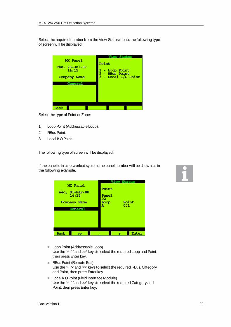
Select the required number from the View Status menu, the following type of screen will be displayed:
Select the type of Point or Zone:
1 Loop Point (Addressable Loop).
2 RBus Point.
3 Local I/O Point.
The following type of screen will be displayed:
If the panel is in a networked system, the panel number will be shown as in the following example.
Loop Point (Addressable Loop)Use the ‘+’, ‘-’ and ‘>>’ keys to select the required Loop and Point, then press Enter key.
RBus Point (Remote Bus)Use the ‘+’, ‘-’ and ‘>>’ keys to select the required RBus, Category and Point, then press Enter key.
Local I/O Point (Field Interface Module)Use the ‘+’, ‘-’ and ‘>>’ keys to select the required Category and Point, then press Enter key.
Point
1 - Loop Point2 - RBus Point3 - Local I/O Point
MX Panel
Thu, 26-Jul-07 14:15
Company Name
General
Back
View Status
Point
Panel02Loop Point A 001
MX Panel
Wed, 01-Mar-08 14:15
Company Name
General
Back
View Status
>> - + Enter
Doc. version 1 29

MZX 125/250 Fire Detection Systems
The following type of screen will be displayed:
Point Input and Point Output are displayed in the same format.
The top line shows the selected option.
The second line shows the Zone and Point number of the device.
The third line shows the Sector description (defined at configuration).
The fourth line shows the Zone description (defined at configuration).
The fifth line shows the Point description (defined at configuration).
The sixth line shows the device type.
Actual Status Input can be in one of the following states:
Normal
Fault
Active
PreAlarm
Actual Status Ootput can be in one of the following conditions:
On
Off
Pulse 1
Pulse 2
Selecting Zone will display the following type of screen:
PointZone 006 A007
Zone 06Call alarm in roomCP 820
Input Output
Normal
MX Panel
Thu, 26-Jul-07 14:15
Company Name
General
Back
View Status
Zone 002South Building1st Floor Corridoor
Alarm : NO*Fault : NO*Isolate : NONE**Walk Test : NO*
MX Panel
Thu, 26-Jul-07 14:15
Company Name
General
Back
View Status
_ +
30 Doc. version 1

MZX125/250 Fire Detection Systems
Screen display (the asterisks are not shown on the screen):
*YES/NO
**NONE/ PARTIAL/ALL
Function Keys F3/F4 will decrement/increment the zone number.
4.7 ISOLATE/DE-ISOLATE
The Isolate/De-isolate option allows the following to be isolated/de-isolated:
Point Complete 1
Point Input 2
Point Output 3
Zone Detectors 4
Zone Callpoints(also interrupt devices)5
Zone Alarm I/Ps 6
Zone Sounders 7
Zone Controls 8
Zone Extinguish 9
Extinguish ControlsF2
Fault Signalling F3
Alarm Signalling F4
All Sounders F5
Press 3 from the Main menu. The following screen will be displayed:
Description
Alarm Yes One or more devices of a zone in Alarm Mode
Fault Yes One or more devices of the zone in Fault Mode
Isolate All All alarm input devices of the zone are Isolated
Isolate Partial At least one, but not all alarm input devices are Isollated
Walk Test Yes All alarm input devices of the zone in Walk Test
Doc. version 1 31

MZX 125/250 Fire Detection Systems
Select the required number from the Isolate/De-Isolate menu, then select the type of point (as described in Section 3.5):
Loop Point (Addressable Loop)Use the ‘+’, ‘-’ and ‘>>’ keys to select the required Loop and Point, then press Enter key.
RBus Point (Remote Bus)Use the ‘+’, ‘-’ and ‘>>’ keys to select the required RBus, Category and Point, then press Enter key.
Local I/O Point (Field Interface Module)Use the ‘+’, ‘-’ and ‘>>’ keys to select the required Category and Point, then press Enter key.
CAUTION:
Isolating I/O points may break compliance with EN54. Caution should be exercised when dealing with mandatory switches and indicators. Such operations are reserved for authorised trained
personnel only.
The following screen shows an example of Point isolation:
In the ‘Customer Operator’ access levels, only points on the addressable loop can be isolated or de-isolated.
1 - Point2 - Point I/P only3 - Point O/P only4 - Zone Detectors5 - Zone Callpoints6 - Zone Alarm I/Ps7 - Zone Sounders8 - Zone Controls9 - Zone Extinguish
MX Panel
Thu, 26-Jul-07 14:15
Company Name
General
Back
Isolate/De-Isolate
Alm Sig All SNDFlt SigExt.Ctl
Point CompleteZone 002 B002South Building1st Floor CorridoorRoom 117801 H
Status IP: NormalISOLATED INPUT
1 - Isolate 2 - De-Isolate
MX Panel
Thu, 26-Jul-07 14:15
Company Name
Isola 001
General
Back
Isolate/De-Isolate
Isolation Status
32 Doc. version 1

MZX125/250 Fire Detection Systems
Isolations are counted and displayed (eg, Isol 001). If only the input or output of a point is isolated, this is counted as a complete isolation of the point.
The following screen shows an example of Zone isolation:
Successes: Number of points that wereDe-Isolated
Matches: Number of points in Zone (detectors)
The following screen shows an example of All Sounders isolation:
Successes: Number of sounders (De-)Isolated
Matches: Number of sounders in Zone
Zone DetectorsZone 001
Zone 01
IsolateAll
Successes : 003Matches : 003
MX Panel
Thu, 26-Jul-07 14:15
Company Name
Isola 003
General
Back
Isolate/De-Isolate
All Sounders
Successes : 006Matches : 006
MX Panel
Thu, 26-Jul-007 14:15
Company Name
Isola 006
General
Back
Isolate/De-Isolate
Doc. version 1 33

MZX 125/250 Fire Detection Systems
4.8 TIME/DATE
Press 4 from the Main menu. The following type of screen will be displayed:
4.8.1 SET TIME/DATE
Press 1 from the Time/Date menu. The following type of screen will be displayed:
Use the ‘>>’ key to move the cursor between options, enter date and time values via the keypad or Softkey F3 (‘-’) and F4 (‘+’).
When a value has been changed, F5 shows ‘Save’, use this key when all editing has been completed.
Months January to September can also be entered with the keypad:
1 = January ...................
9 = September
1 - Set Time/Date2 - Summer/Winter
MX Panel
Thu, 26-Jul-07 14:15
Company Name
General
Back
Time / Date
MX Panel
Thu, 26-Jul-07 14:15
Company Name
General
Back
Time / Date
>> - +
Date : 01-Mar-00Time : 14:15:17
Save
34 Doc. version 1

MZX125/250 Fire Detection Systems
4.8.2 SUMMER/WINTER
Press 2 from the Time/Date menu. The following type of screen will be displayed:
These screens cannot be changed, use F5 to toggle between Winter and Summer.
4.9 EVENT LOG
Press 5 from the Main menu. The following type of screen will be displayed:
Summertime MX Panel
Thu, 26-Jul-07 14:15
Company Name
General
Back
Summer/Winter
Winter
1 - View Event Log2 - Print Event Log3 - Filter
MX Panel
Thu, 26-Jul-07 00:01
Company Name
General
Back
Event Log
Doc. version 1 35

MZX 125/250 Fire Detection Systems
4.9.1 VIEW EVENT LOG
This option allows all events in the event log to be viewed or printed.
Select option 1 from the Event Log menu, the following type of screen will be displayed:
The latest event is displayed, use the ‘<<’ and ‘>>’ keys to scroll through the log and the ‘|<<’ to move to the back of the log or the ‘>>|’ key to move to the front of the log.
EventID - Displays the absolute number of an event (1 to 65,535). After 65,535 it starts with 1 again.
0001/0010 - The first number is the actual position in the event log (1 means it displays the newest event log entry. The second number displays the number of entries in the event log (max. 3,000).
The newest/last event will be displayed when the Event Log is entered.
4.9.2 PRINT EVENT LOG
Select option 2 from the Event Log menu, the following type of screen will bedisplayed:
This menu option is only available if at least one printer is configured.
The destination printer can be selected if more than one printer is configured.
Zone 000System Zone
TEST FINISHED
04-Feb-02 19:30:00- Empty -Information only 0001/0010
MX Panel
Thu, 26-Jul-07 14:15
Company Name
General
Back
Event Log
<< >>>><<
MX Panel
Thu, 26-Jul-07 14:15
Company Name
General
Back
Event Log
Destination :Default Printer
How far back:to start: 0010
How many entriesrequired: 0010
Lowest priorityof interest : 00 Print initiated
36 Doc. version 1

MZX125/250 Fire Detection Systems
The priorities available are shown in the following table:
It is always printed from the selected priority (eg, Non Life Risk) to the Highest Priority (eg, Non Life Risk, Level 12, Life Risk Alarm and General Alarm).
4.9.3 FILTER
Select option 3 from the Event Log menu, the following type of screen will bedisplayed:
It is possible to view and to print the events of single categories. The category is selected by pressing the appropriate option number. It is also possible to select several categories, the selected categories are denoted by a ‘+’ sign.
Press F4 to view the selected categorie(s) as described in Section 3.8.1 or F5 to print the selected category(s) as described in Section 3.8.2.
Lowest Priority Information Only. Level 2. Expected Events. Isolates. Warnings. Visible Isolate. Other Faults. Critical Faults. Gas Alert. Alarm Threshold. Non-Life Risk . Level 12. Life Risk AlarmsHighest Priority General Alarm
1 - Fire -2 - Gas Alert -3 - Pre Alarm -4 - Supervisory -5 - Fault -6 - Isolate -7 - Test Mode -8 - Warning -9 - Information -
MX Panel
Thu, 26-Jul-07 14:15
Company Name
General
Back
Event Log
PrintView
Doc. version 1 37

MZX 125/250 Fire Detection Systems
4.10 VIEW/PRINT STATUS
Allows the following options to be viewed/printed. On networked systems, thestatus of any panel on the network may be viewed/printed:
Points Isolated
Points Untested/Failed (during Walk Test)
Point Values
View Faults (no print option)
Loop Point Counters (no print option)
Select option 6 from the Main menu, the following type of screen will be displayed:
4.10.1 VIEW/PRINT POINTS ISOLATED
Select option 1 from the View/Print Status menu, the following type of screen will be displayed:
If the panel is part of a networked system, another screen is displayed before the above screen where the panel number may be selected.
1 - Points Isolated2 - Pts Unt./Failed3 - Point Values4 - View Faults5 - Loop Point Ctrs
7 - Active Points8 - By Function
MX Panel
Wed, 01-Jan-08 14:15
Company Name
General
Back
View/Print Data
InputTotal : 004
Zone 001 -001 BPoint Text--------------------001 -002 BPoint Text
MX Panel
Thu, 26-Jul-07 14:15
Company Name
General
Back
Points Isolated
PrintOutput
38 Doc. version 1

MZX125/250 Fire Detection Systems
Press F5 ‘Print’ to print a list of all isolated points.
The F2 Key selects either isolated inputs or isolated outputs.
Points which are completely isolated (input and output) will be shown in both lists.
4.10.2 VIEW/PRINT POINTS UNTESTED/FAILED
This option only works whilst still in Walktest.
Select option 2 from the View/Print Status menu, the following type of screen will be displayed:
If the panel is part of a networked system, another screen is displayed before the above screen where the panel number may be selected.
Press F5 to print the Untested/Failed points.
Points which are not tested or points which return the wrong condition are then listed.
Total : 004
Zone 001 -001 BPoint Text--------------------Zone 001 -002 BPoint Text
MX Panel
Thu, 26-Jul-07 14:15
Company Name
General
Back
Pts Untested/Failed
Doc. version 1 39

MZX 125/250 Fire Detection Systems
4.10.3 VIEW/PRINT POINT VALUES
Select option 3 from the View/Print Status menu, the following type of screen will be displayed:
Select the panel number (if the panel is part of a networked system), loop and point number required.
‘>>’ - next field
‘_’ - the number is decremented
‘+’ - the number is incremented
Pressing F5 displays the following screen:
Press F5 to print the Point Values of the selected loop (not only the displayed point).
Panel 02
Loop PointA 002
MX Panel
Thu, 26-Jul-07 14:15
Company Name
General
Back
Point Values
Enter >> - +
Zone 002 B002South Building1st Floor CorridoorRoom 117 801H
Real: 801 H (020)Mode: 1 Sens.: 0 20 C (032)
MX Panel
Thu, 26-Jul-07 14:15
Company Name
General
Back
Point Values
o
40 Doc. version 1

MZX125/250 Fire Detection Systems
4.10.4 VIEW FAULTS
Select option 4 from the View/Print Status menu, the following type of screen will be displayed:
This option is view only.
4.10.5 VIEW LOOP POINT COUNTERS
This option is view only. Select option 5 from the View/Print Status menu, the following screen will be displayed:
Only the Loop will be shown if the panel is not networked.
Select the required panel (only if the panel is networked) and loop, then press the Enter key. The following message is displayed:
Please Wait...
for approximately 2 minutes until the count is complete, if no faults are found, the following type of screen will be displayed:
Total : 002
Zone 000 R10Zone 000 R12
MX Panel
Wed, 01-Jan-08 14:15
Company Name
Flt P 002
General
Back
View Faults
Panel02
LoopA
MX Panel
Thu, 26-Jul-07 14:15
Company Name
General
Back
Loop Point Counters
>> - + Enter
Doc. version 1 41

MZX 125/250 Fire Detection Systems
Configured - the number of points configured.
Conditions for ‘PASSED’
The number of configured points is equal the detected count of points on the loop.
There are no unconfigured points.
Detected points from left, right and both sides are equal.
If all conditions are not satisfied, the ‘ATTENTION’ screen will be displayed showing the relevant counters.
Configured - the number of points configured.
Conf & Ident - shows how many points are connected, identified and configured on the loop.
Not Conf. - shows how many points were identified on the loop but not configured.
Both Sides/Left Side/Right Side - Shows how many points on the loop are recognised by the panel. ‘Left Side’ and ‘Right Side’ is the count from both sides. ‘Both Sides’ means the detection of a closed loop.
If the value of ‘Conf & Ident’ is different to the number of installed devices, multiple reserved address may be the cause.
CounterLoop : A PASSED
Configured : 010
MX Panel
Thu, 26-Jul-07 14:15
Company Name
General
Back
Loop Point Counters
Details Scan
CounterLoop : A A T T E N T I O N
Configured : 010
Conf. & Ident: 009
MX Panel
Thu, 26-Jul-07 14:15
Company Name
General
Back
Loop Point Counters
Details Scan
42 Doc. version 1

MZX125/250 Fire Detection Systems
4.10.5.1 DETAILS
Press the ‘Details’ key (F2), the following type of screen will be displayed:
All 250 addresses may be displayed using the ‘>>’ key.
The connection detail of each point is shown by the following symbols:
Function key F2 scrolls through the loop.
4.10.5.2 SCAN
Press the ‘Scan’ key (F3), the following type of screen will be displayed:
The points are shown which were detected from both sides (Left/Right).
They are displayed as follows:
o OK: point connected, configured and identified (eg, point 33 and points 60 to 64)Point was configured but not connected or identified (eg, point 21)
Point was not configured but connected (eg, point 6)
MX Panel
Thu, 26-Jul-07 14:15
Company Name
General
Back
Loop Point Counters
>>
DetailsLoop : APoint 0123456789 0 : ......u... 10 : .......... 20 : .c........ 30 : ...o...... 40 : .......... 50 : .......... 60 : ooooo..... 70 : .......... 80 : ..........
c
u
MX Panel
Thu, 26-Jul-07 14:15
Company Name
General
Back
Loop Point Counters
>>
Left / Right ScanLoop : APoint 0123456789 0 : ....l..... 10 : .......... 20 : .l........ 30 : ...*...... 40 : .......... 50 : .......... 60 : rrrrr..... 70 : .......... 80 : ..*.......
Doc. version 1 43

MZX 125/250 Fire Detection Systems
Function key F2 scrolls through the loop.
4.10.6 ACTIVE POINTS
Select option 7 from the View/Print Status Menu. The following type of screen will be displayed:
4.10.6.1 FIRE INPUTS
Select option 1 from the Active Points menu, the following screen will be displayed:
Empty (not used)
OK: detected from both sides (eg, points 33 and 82)
Only detected from left side (eg, points 4 and 21)
Only detected from right side (eg, 60 to 64)
.
*
l
r
1 - Fire Inputs2 - Non-Fire Inputs3 - Loop Outputs4 - Sounders
MX Panel
Wed, 01-Jan-08 14:15
Company Name
General
Back
Active Points
MX Panel
Wed, 21-Aug-07 08:01
Company Name
General
Back
Active Points
Current active pts.Total : 0
Iso&Act Print
44 Doc. version 1

MZX125/250 Fire Detection Systems
Pressing Iso&Act (F2) will display the following screen:
Pressing Iso&For (F2) will display the following screen:
4.10.7 BY FUNCTION
Select option 8 from the View/Print Status Menu. The following type of screen will be displayed:
Screens for options 2, 3 and 4 are the same type as for option 1 Fire Inputs.
MX Panel
Wed, 21-Aug-07 08:01
Company Name
General
Back
Active Points
Isolated active ptsTotal : 0
Iso&For Print
MX Panel
Wed, 21-Aug-07 08:01
Company Name
General
Back
Active Points
Isolated active ptsTotal : 0
Iso&For Print
MX Panel
Wed, 21-Aug-07 08:01
Company Name
General
Back
By Function
1 - Fire Inputs2 - Non-Fire Inputs3 - Loop Outputs4 - Sounders5 - Protection Eqp.6 - Plant Equipment
Doc. version 1 45

MZX 125/250 Fire Detection Systems
4.10.7.1 FIRE INPUTS
Select option 1 from the By Function menu, the following screen will be displayed:
Select option 1 from the Fire Inputs menu, the following screen will be displayed:
Select option 2 from the Fire Inputs menu, the following screen will be displayed:
Select option 3 from the Fire Inputs menu, the following screen will be displayed:
MX Panel
Wed, 21-Aug-07 08:01
Company Name
General
Back
Fire Inputs
1 - Active2 - Fault3 - Isolated
MX Panel
Wed, 21-Aug-07 08:01
Company Name
General
Back
Active Fire IPs
Panel: 1Total : 0Page : 0/ 0
MX Panel
Wed, 21-Aug-07 08:01
Company Name
General
Back
Fire IPs in Fault
Panel: 1Total : 0Page : 0/ 0
46 Doc. version 1

MZX125/250 Fire Detection Systems
4.11 SERVICE
Press 7 from the Main menu. The following type of screen will be displayed:
The Maintenance and Diagnostics options are only available at Customer Manager level and will not be displayed for lower levels.
4.11.1 WALK TEST
When selected, this option allows single or multiple points to be tested without an alarm being raised.
Press 1 from the Service menu.
Only one Walk Test session can be active at one time.
MX Panel
Wed, 21-Aug-07 08:01
Company Name
General
Back
Isolated Fire IPs
Panel: 1Total : 0Page : 0/ 0
1 - Walk Test2 - Maintenance
MX Panel
Wed, 09-Aug-08 00:01
Company Name
General
Back
Service
Doc. version 1 47

MZX 125/250 Fire Detection Systems
Use the ‘>>’, ‘-’ and ‘+’ keys to select the required options. The Panel number is only displayed when it is part of a networked system.
Depending on the selected settings, the display will change. The following screen is an example of ‘Area’ selected as ‘Point’.
To start the Walk Test press F5.
Possible Settings
Panel
Panel selection is only available for panels that are in a networked system.
Area
All Walk Test of all elements of a specific type.(Selection in the field ‘Type’ eg, callpoints).
Zone Walk Test of all elements of a specific type in a special zone.
Point Walk Test of the input of a single point.
Panel : 01Area : AllType : InputLoop : All
Mode : MANUAL
Multisensor : Part
MX Panel
Wed, 09-Mar-08 00:01
Company Name
General
Back
Walk test
>> + - Start
Panel : 01Area : PointType : InputLocation : LoopZone : 01Point : 01
Mode : MANUAL
Multisensor : Part
MX Panel
Thu, 26-Jul-07 00:01
Company Name
General
Back
Walk test
>> + - Start
48 Doc. version 1

MZX125/250 Fire Detection Systems
Type
Loop
Only with Area as ‘All’ or ‘Zone’.
Walk Test of all loops or of a specific loop (A, B, C or D).
Location
Only with Area selected as ‘Point’.
Zone
Only with Area selected as ‘Point’.
Point
Only with Area selected as ‘Point’.
Selection of a specific zone is possible.
Mode
MANUAL
Detectors to be tested manually.
AUTOMATIC
Only if type selected is ‘detector’
813P
This mode is only available if an 813P detector is configured. If an 813P detector fails this test, it must be manually tested to confirm the failure.
Multisensor
It is only possible to select either ‘Automatic’, ‘Lasertest’ or ‘Multisensor. The panel itself prevents selection of more than one option.
Input Walk Test of all inputs.Detectors Walk Test of detectors.Alarm I/Ps Walk Test of default inputs covered by
supergroup ‘Fire Alarm Inputs SG’.Call Points Walk Test of call points.Sounders Walk Test of sounders by loop or all
loops plus FIM sounders.
Loop A point on the loop.
Loop Selection of a specific zone is possible.
Self test will be carried out by detectors.The following detectors support the self test function:
801PH801CH801I
801PHEx801CHEx
FullPart
Doc. version 1 49

MZX 125/250 Fire Detection Systems
If ‘Full’ Walk Test is selected, both modes of the detector must be activated (eg, both heat and optical mode for 801PH).
If ‘Part’ Walk Test is selected, the detector has to be activated in the mode in which it is operating (eg, for 801PH optical and heat, both modes active, then activation of either the optical or heat will activate the processing. If only the heat mode is active, then only activation of the heat mode will create an alarm.
4.11.1.1 ALL INPUTS
Select the following settings:
Area: All
Type: Input
Loop: All
Press F5 to start the Walk Test.
The following screen shows an example for the Walk Test ‘All Inputs’ option:
Press F3 to display selected settings.
Press F5 to end Walk Test.
CAUTION:
THE FINISHING OF A WALK TEST IS ONLY POSSIBLE IF ALL POINTS IN THE WALK TEST ARE INACTIVE.
Selected: Number of points selected by the test.Excluded: Number of Points not in Walk Test (ie,
points isolated).Been Active: Number of points which have been
activated during Walk Test.Been Clear: Number of points which were not
active when starting Walk Test.Successful: Number of tested points.Curr.Active: Points which are currently active.TestZ: Number of zones which are in Walk
Test. The pointer is only counted if all points in a zone are in Walk Test.
All Inputs
Selected : 007Excluded : 000Been Active : 005Been Clear : 007Successful : 005Curr.Active : 000
MX Panel
Wed, 09-Mar-08 00:01
Company Name
General
Back
Walk test
Settings End
TestZ 001
50 Doc. version 1

MZX125/250 Fire Detection Systems
4.11.1.2 SOUNDERS
Select ‘Sounders’ in the Type field.
No results will be shown on the display. The selected sounders will be activated in a pulsing mode.
4.11.1.3 POINT
Select the following settings:
Press F5 to start the Walk Test.
The following screen shows an example for the Walk Test of ‘Point Input’:
Press F3 for a display of selected settings.
Press F5 to end Walk Test.
CAUTION:
THE FINISHING OF A WALK TEST IS ONLY POSSIBLE IF ALL POINTS IN THE WALK TEST ARE INACTIVE.
Area: Point.Type: Input (appears automatically).Location: Loop (appears automatically).Zone: Required number.Point: Required number.
Selected: 1, if point is in Walk test.Excluded: 1, if point is not in Walk Test (ie, if point
is isolated).Activations: 1, if point was activated during Walk
Test.Curr.Active: Yes, if point is currently active.TestZ 001 Number of zones which are in Walk
Test. (The pointer is only counted if all points of a zone are in Walk Test. If one detector on the zone is switched off, the pointer is not decreased. In the case of Walk Test for one point, the pointer is only decreased if that point is the only point on the zone).
Point I/P onlyZone 006 A007
Zone 06Call alarm in roomCP820
Selected : 1Excluded : 0Activations : 0Curr.Active : NO
MX Panel
Wed, 09-Mar-08 00:01
Company Name
General
Back
Walk test
Settings End
TestZ 001
Details
Doc. version 1 51

MZX 125/250 Fire Detection Systems
4.11.2 MAINTENANCE
Press 2 from the Service menu. The following type of screen will be displayed:
4.11.2.1 VIEW FIRE ALARM CYCLE COUNT
When selected, the number of Alarm sequences may be viewed.
Press 1 from the Maintenance menu. The following type of screen will be displayed:
4.11.2.2 VIEW/PRINT MAINTENANCE REQUEST
When selected, this option displays a list of detectors which are near the limit of their threshold compensation limit.
Press 3 from the Maintenance menu. The following type of screen will be displayed:
1 - Fire Cycle Count
3 - Maint. Request4 - Battery Test
6 - Project Numbers7 - S/W Versions
9 - Menu Points
MX Panel
Wed, 01-Mar-08 14:15
Company Name
General
Back
Maintenance
Count :
0025
MX Panel
Wed, 01-Mar-08 14:15
Company Name
General
Back
Fire AL.Cycle Count
52 Doc. version 1

MZX125/250 Fire Detection Systems
Press F5 to print the Maintenance Request.
4.11.2.3 BATTERY TEST
When selected, this option allows the state of the battery and the charger current to be displayed.
Press 4 from the Maintenance menu. The following type of screen will be displayed:
4.11.2.4 PROJECT NUMBERS
When selected, this option allows the project and MX CONSYS information to be displayed.
Press 6 from the Maintenance menu. The following type of screen will be displayed:
Total : 003
Zone 002 B002Zone 004 A126Zone 008 B006
MX Panel
Wed, 01-Mar-08 14:15
Company Name
General
Back
Maintenance Request
Battery State :Battery Low
Battery Voltage :20.764 V
Charger Current :00.500 A
MX Panel
Wed, 01-Mar-08 14:15
Company Name
General
Back
Battery Test
Project:Queen El. Hospital
Consys: V10.0Version: 34Created:21-Jul-07 10:18Downloaded:27-Jul-07 08:20
MX Panel
Wed, 01-Mar-06 00:01
Company Name
General
Back
Project Numbers
Doc. version 1 53

MZX 125/250 Fire Detection Systems
4.11.2.5 SOFTWARE VERSIONS
When selected, the software versions of the following are displayed:
Firmware
Local I/O
Each Loop
Each MPM
Network card (if fitted)
Press 7 from the Maintenance menu. The following type of screen will be displayed:
Press F5(+) for additional details of the software versions.
4.11.2.6 MENU POINTS
When selected, this option allows any configured point displayed to be operated by pressing the appropriate number button, this will toggle from OFF to ON and ON to OFF.
Press 9 from the Maintenance menu. The following type of screen will be displayed:
-Firmware V 10.0 -Bootrom V 1.2 -Local I/O V 1.0 -Loop A V 2.1 -Loop B V 2.1 -OCM00 V 2.0 -OCM01 V 2.0
MX Panel
Thu, 26-Jul-07 14:15
Company Name
General
Back
Software Versions
MX Panel
Wed, 01-Mar-08 14:15
Company Name
General
Back
Menu Points
>>
Menu Point 1: OFFIsolate Zone
Menu Point 2: ONSensit.Change
Menu Point 3: -Unconfigured-
Menu Point 4: -Unconfigured-
ON
54 Doc. version 1

MZX125/250 Fire Detection Systems
4.11.3 CONFIGURATION
Press 8 from the Main menu. The following screen will be displayed:
‘Menu option 9- Restart’ will only be displayed if text has been changed and the changes saved.
RESTRICTIONS ON THE USE OF THE FOLLOWING OPTION
When using Configuration menu option 1, ALWAYS commit configuration changes by using ‘Menu option 9 - Restart’ before leaving the panel.
Avoid ‘inactivity’ timeouts.
NEVER use the ‘Back’ option from the configuration menu if ‘Menu option 9 - Restart’ is showing.
If you do not want to commit changes, by using ‘Menu option 9 - Restart’, option, turn the keyswitch to ‘OFF’ position to avoid a timeout situation, do NOT USE the ‘Back’ option.
Configuration changes across a network are possible, but changes to more than one panel at a time MUST NOT be attempted within one session. When a panels configuration has been changed, it must be restarted using menu option 9 ‘Restart’.
Failure to comply with these restrictions may lead to unpredictable effects or system instability.
4.11.3.1 CHANGE TEXT
Press 1 from the Configuration menu. The following screen will be displayed:
MX Panel
Wed, 01-Mar-08 14:15
Company Name
General
Back
Configuration
1 - Change Text
MX Panel
Wed, 01-Mar-08 14:15
Company Name
General
Back
Change Text
1 - Point Text2 - Zone Text3 - Sector Text4 - Panel Text5 - Info Text
Doc. version 1 55

MZX 125/250 Fire Detection Systems
4.11.3.2 POINT TEXT MODIFY
Press 1 from the Change Text menu. The following screen will be displayed:
Select the required loop and point then press Enter. The following type of screen will be displayed:
‘>>’ - copies the ‘old text’ to the ‘New text’ position.
‘-’ moves the cursor back one position.
‘+’ moves the cursor forward one position.
Modify the old text or insert new text using the alphanumeric keypad, when finished press Enter.
Pressing the scroll up key allows text to be entered in upper case.
Pressing the scroll down key changes to lower case text.
The message ‘Save Data?’ appears and the functions change F4 to ‘Yes’ and F5 to ‘No’. Selecting F5 allows the text modifications to be changed.
Selecting F4 ‘Yes’ displays the message:
Please wait.....
then the following screen is displayed:
MX Panel
Wed, 01-Mar-08 14:15
Company Name
General
Back
Point Text Modify
Loop : APoint : 001
>> - + Enter
MX Panel
Wed, 01-Mar-08 14:15
Company Name
General
Back
Point Text Modify
Zone 255 -007 A
Old textCallp. alarm room
New text
>> - + Enter
56 Doc. version 1

MZX125/250 Fire Detection Systems
It is now possible to change the text for another Point.
Selecting F1 ‘Back’ will display the following screen:
Only ‘Change Text’ and ‘Restart’ are available allowing more points to be changed or using ‘Restart’ to allow the changes to take effect.
4.11.3.3 ZONE TEXT MODIFY
Press 2 from the Configuration menu. The following screen will be displayed:
Select the required and press Enter. The following type of screen will be displayed:
MX Panel
Wed, 01-Mar-08 14:15
Company Name
General
Back
Change Text
1 - Point Text
MX Panel
Wed, 01-Mar-08 14:15
Company Name
General
Back
Configuration
1 - Change Text
9 - Restart
MX Panel
Wed, 01-Mar-08 14:15
Company Name
General
Back
Zone Text Modify
Zone : 001
- + Enter
Doc. version 1 57

MZX 125/250 Fire Detection Systems
‘>>’ - copies the ‘old text’ to the ‘New text’ position.
‘-’ moves the cursor back one position.
‘+’ moves the cursor forward one position.
Modify the old text or insert new text using the alphanumeric keypad, when finished press Enter.
The message ‘Save Data?’ appears and the function change F4 to ‘Yes’ and F5 to ‘No’. Selecting F5 allows the text modifications to be changed.
Selecting F4 ‘Yes’ displays the message:
Please wait.....
then the following screen is displayed:
It is now possible to change the text for another Zone.
Selecting F1 ‘Back’ will display the following screen:
MX Panel
Wed, 01-Mar-08 14:15
Company Name
General
Back
Zone Text Modify
Zone : 001
Old textZone 01
New text
>> - + Enter
MX Panel
Wed, 01-Mar-08 14:15
Company Name
General
Back
Change Text
2 - Zone Text
MX Panel
Wed, 01-Mar-08 14:15
Company Name
General
Back
Configuration
1 - Change Text
9 - Restart
58 Doc. version 1

MZX125/250 Fire Detection Systems
Only ‘Change Text’ and ‘Restart’ are available allowing more points to be changed or using ‘Restart’ to allow the changes to take effect.
4.11.3.4 SECTOR TEXT MODIFY
Press 3 from the Configuration menu. The following screen will be displayed:
Select the required sector, then press Enter. The following type of screen will be displayed:
‘>>’ - copies the ‘old text’ to the ‘New text’ position.
‘-’ moves the cursor back one position.
‘+’ moves the cursor forward one position.
Modify the old text or insert new text using the alphanumeric keypad, when finished press Enter.
The message ‘Save Data?’ appears and the function change F4 to ‘Yes’ and F5 to ‘No’. Selecting F5 allows the text modifications to be changed.
Selecting F4 ‘Yes’ displays the message:
Please wait.....
MX Panel
Wed, 01-Mar-08 14:15
Company Name
General
Back
Sector Text Modify
Sector : 001
- + Enter
MX Panel
Wed, 01-Mar-08 14:15
Company Name
General
Back
Sector Text Modify
Sector 001
Old textSector 01
New text
>> - + Enter
Doc. version 1 59

MZX 125/250 Fire Detection Systems
then the following screen is displayed:
It is now possible to change the text for another Sector.
Selecting F1 ‘Back’ will display the following screen:
4.11.3.5 PANEL TEXT MODIFY
Press 4 from the Configuration menu. The following screen will be displayed:
Select the required Panel.
‘>>’ - copies the ‘old text’ to the ‘New text’ position.
‘-’ moves the cursor back one position.
‘+’ moves the cursor forward one position.
MX Panel
Wed, 01-Mar-08 14:15
Company Name
General
Back
Change Text
3 - Sector Text
MX Panel
Wed, 01-Mar-08 14:15
Company Name
General
Back
Configuration
1 - Change Text
9 - Restart
MX Panel
Wed, 01-Mar-08 14:15
Company Name
General
Back
Panel Text Modify
Panel 00
Old Text ADT
New Text
Enter>> - +
60 Doc. version 1

MZX125/250 Fire Detection Systems
Modify the old text or insert new text using the alphanumeric keypad, when finished press Enter.
The message ‘Save Data?’ appears and the function change F4 to ‘Yes’ and F5 to ‘No’. Selecting F5 allows the text modifications to be changed.
Selecting F4 ‘Yes’ displays the message:
Please wait.....
then the following screen is displayed:
It is now possible to change the text for another Panel.
Selecting F1 ‘Back’ will display the following screen:
4.11.3.6 INFO TEXT MODIFY
This option allows Info Text created in CONSYS to be modified. Press 5 fromthe Change Text menu. The following screen will be displayed:
MX Panel
Wed, 01-Mar-08 14:15
Company Name
General
Back
Change Text
4 - Panel Text
MX Panel
Wed, 01-Mar-08 14:15
Company Name
General
Back
Configuration
1 - Change Text
9 - Restart
MX Panel
Wed, 01-Mar-08 14:15
Company Name
General
Back
Info text modify
- + Enter
Infotext No. : 001
Doc. version 1 61

MZX 125/250 Fire Detection Systems
Using the ‘+’ and ‘-’ keys select the Info Text message to modify, then press‘Enter’.
The following type of screen will appear:
The ‘>>’ key deletes all text.
The ‘+’ key advances the cursor one space, the ‘-’ key goes one space back.
Use the alphanumeric keys to modify the text, when finished, press ‘Enter’.
The following screen will be displayed:
MX Panel
Wed, 01-Mar-08 14:15
Company Name
General
Back
Info text modifyInfotext No. : 001
+ Enter
This zone is in aHazardous AreaSpecialprecautionsare required
->>
MX Panel
Wed, 01-Mar-08 14:15
Company Name
General
Back
Info text modifyInfotext No. : 001
Save data?
Yes No
This zone is in aHazardous AreaSpecialprecautionsare required
62 Doc. version 1

MZX125/250 Fire Detection Systems
5 ROUTINE CHECKS
5.1 GENERAL
In order to comply with the requirements of British Standard BS 5839 Part 1, the installation must be checked on a regular basis by a responsible member of staff to confirm that the controller and all ancillary devices are operating correctly. The required routine checks are described in the following paragraphs.
5.2 DAILY CHECKS
Proceed as follows:
1 Ensure the front panel of the controller is indicating a normal condition (ie, no alarm or fault LEDs are lit and the LCD is displaying the date and time).
If the panel is not indicating a normal condition record the condition in the log book and take any necessary action.
2 Check that any fault recorded on the previous day has received attention.
5.3 WEEKLY CHECKS
These checks would normally be carried out by a responsible member of the customer’s staff.
WARNING:
WARN ALL PERSONNEL THAT THE SOUNDERS ARE ABOUT TO BE TESTED.
Proceed as follows:
1 If necessary, clean the front panel of the controller with a suitable cleansing agent.
Doc. version 1 63

MZX 125/250 Fire Detection Systems
2 Set one device (either a callpoint or detector) from one zone into alarm and check that the system responds as follows:
• The controller’s internal buzzer sounds in a continuoustone.
• The two red ‘FIRE’ LEDs on the controller front panel light.
• The appropriate red ‘FIRE ZONAL’ LED flashes (ifconfigured).
• The general and zonal sounders operate.
• The alphanumeric display gives the location of the alarm.
1 Record the device used to initiate the test in the site log book and reset the controller.
2 Check the condition of the printout on any printers attached to the system and replace the ribbon if it is becoming feint.
3 Ensure that each printer has an adequate supply of paper.
Any defect should be recorded in the log book and appropriate action taken.
64 Doc. version 1

V1.0/13/11/08
Tyco Safety Products
Dunhams Lane
Letchworth Garden City
Hertfordshire
SG6 1BE
120.415.992


