
Minerals Industry Safety Handbook Part-4 · Minerals Industry Safety Handbook ... Fixed–wing...
190
PART 4 WORKING ENVIRONMENT UPDATED January 2004
Transcript of Minerals Industry Safety Handbook Part-4 · Minerals Industry Safety Handbook ... Fixed–wing...

PART 4
WORKING
ENVIRONMENT
UPDATED January 2004

Page 2 Part 4: Working Environment
January 2004
Minerals Industry Safety Handbook
Part 4: Working Environment Page 3
January 2004
Minerals Industry Safety Handbook
Page 2 Part 4: Working Environment
January 2004
Minerals Industry Safety Handbook
Part 4: Working Environment Page 3
January 2004
Minerals Industry Safety Handbook
PART 4: WORKING ENVIRONMENT
4.1 FEASIBILITY, DESIGN AND PLANNING 17
4.1.1 IDENTIFY CORE RISKS 17 4.1.2 REVIEW CORE RISKS 17
4.2 EXPLORATION 18
4.2.1 GENERAL 18
4.2.2 INDUCTIONS AND TRAINING 18
4.2.2.1 General 18
4.2.2.2 Site–specific 19
4.2.3 FIELD WORK 20
4.2.3.1 Prospecting, mapping and soil/rock sampling 20
4.2.3.2 Tracks and gridlines 20
4.2.3.3 Surface excavations 21
4.2.3.4 Abandoned mines 21
4.2.4 AVIATION 21
4.2.4.1 Airborne surveys and logistic support 22
4.2.4.2 Fixed–wing aircraft 23
4.2.4.3 Helicopters 24
4.2.5 VEHICLES AND TRAVELLING 26
4.2.5.1 Vehicle accidents 27
4.2.5.2 Vehicle breakdowns 27
4.2.5.3 Vehicle equipment 28
4.2.6 EXPLOSIVES AND DANGEROUS GOODS IN EXPLORATION 28
4.2.7 EXPLORATION DRILLING 28
4.2.7.1 Planning drill sites 28
4.2.7.2 Selecting drill rigs 29
4.2.7.3 Drilling operations 29
4.2.7.4 Compressors, pumps and high-pressure equipment 31
Reference documents 31
4.3 CONSTRUCTION, BUILDINGS AND STRUCTURES 32
4.3.1 CONSTRUCTION WORK 32
4.3.1.1 Management control 32
Page 4 Part 4: Working Environment
January 2004
Minerals Industry Safety Handbook
Part 4: Working Environment Page 5
January 2004
Minerals Industry Safety Handbook
4.3.1.2 Induction and training 33
4.3.1.3 Planning 33
4.3.2 TRENCHES 35
4.3.2.1 Introduction 35
4.3.2.2 Ground support 36
Reference documents 40
4.3.3 SCAFFOLDING 40
4.3.3.1 Introduction 40
4.3.3.2 Use of scaffolds 40
4.3.3.3 Safe access and provision of ladders 40
4.3.3.4 Supervison 41
4.3.3.5 Personnel 41
4.3.3.6 Construction and maintenance 42
4.3.3.7 Mobile platforms 42
4.3.3.8 Trestle scaffolds 42
4.3.3.9 Falls from scaffolds 43
4.3.3.10 Falling objects 43
4.3.3.11 Emergency care 43
Reference documents 43
4.3.4 BUILDINGS AND STRUCTURES 43
4.3.4.1 Introduction 43
4.3.4.2 Supply of potable water 44
4.3.4.3 Toilet and washing facilities 44
4.3.4.4 Crib rooms 45
4.3.4.5 Change houses 45
4.3.5 CONFINED SPACES 45
4.3.5.1 Checklist 45
Reference documents 46
4.3.6 WORKING AT HEIGHTS 46
4.3.6.1 Risk management 46
4.3.6.2 Control measures 47
4.3.6.3 Fall protection covers 48
4.3.6.4 Working platforms 48
4.3.6.5 Personal fall protection 49
Page 4 Part 4: Working Environment
January 2004
Minerals Industry Safety Handbook
Part 4: Working Environment Page 5
January 2004
Minerals Industry Safety Handbook
4.3.6.6 Methods of fall arrest 50
4.3.6.7 Control after a person has fallen 52
4.3.6.8 Ladders 52
4.3.6.9 Other issues 53
Reference documents 54
4.4 MINE WORKINGS 55
4.4.1 GENERAL 55
4.4.2 SURVEYS AND PLANS 55
4.4.2.1 PLANS 55
4.4.2.2 Mine surveys 55
4.4.3 HOUSEKEEPING 55
4.4.3.1 Dust and dirt removal 56
4.4.3.2 Employee facilities 56
4.4.3.3 Surfaces 56
4.4.3.4 Maintain light fixtures 56
4.4.3.5 Aisles and stairways 56
4.4.3.6 Spill control 57
4.4.3.7 Tools and equipment 57
4.4.3.8 Maintenance 57
4.4.3.9 Waste disposal 57
4.4.3.10 Storage 57
Reference documents 57
4.4.4 MATERIALS HANDLING 57
4.4.4.1 Hung bins, chutes, passes 58
4.4.5 SURFACE EXCAVATIONS 58
4.4.5.1 Opencut over underground workings 58
4.4.5.2 Haul roads 58
4.4.5.3 Methods of working opencuts 58
4.4.5.4 Sand pit 59
4.4.5.5 Clay pit face 59
4.4.6 TAILINGS 59
4.4.6.1 General 59
4.4.6.2 Location 59

Page 6 Part 4: Working Environment
January 2004
Minerals Industry Safety Handbook
Part 4: Working Environment Page 7
January 2004
Minerals Industry Safety Handbook
4.4.6.3 Below–ground storage 60
4.4.6.4 In–pit storage 60
4.4.6.5 Above–ground storage 61
4.4.6.6 Tailings storage structure 62
4.4.6.7 Hazard rating of tailings storage 62
4.4.6.8 Monitoring 63
4.4.6.9 Emergency planning 63
4.4.6.10 Decommissioning and rehabilitation 63
Reference documents 64
4.4.7 UNDERGROUND EXCAVATIONS 64
4.4.7.1 Vertical openings 64
4.4.7.2 Height of backs 64
4.4.7.3 Winzes 65
4.4.7.4 Rises 65
4.4.7.5 Shrink (or shrinkage) stopes 65
4.4.7.6 Alluvial mines, escape drives 65
4.4.7.7 Workings approaching water or gas 65
4.4.7.8 Workings approaching each other 65
4.4.7.9 Ladders 66
4.4.7.10 Access to and from mine workings being developed 66
4.4.7.11 Rail–mounted equipment near shafts 66
4.4.7.12 Exit from mines 66
4.4.7.13 Combustible dusts 67
4.4.7.14 Shafts and excavations to be protected 67
4.4.8 MANAGING HAZARDS 67
4.5 GROUND STABILITY 69
4.5.1 INTRODUCTION 69
4.5.2 GEOLOGICAL STRUCTURE 69
4.5.2.1 Drill core logging 69
4.5.2.2 Geological mapping 69
4.5.3 HAZARD AWARENESS 69
4.5.3.1 Rock conditions 69
4.5.3.2 Rock stress 70

Page 6 Part 4: Working Environment
January 2004
Minerals Industry Safety Handbook
Part 4: Working Environment Page 7
January 2004
Minerals Industry Safety Handbook
4.5.3.3 Rock strength 70
4.5.3.4 Groundwater 70
4.5.3.5 Blasting 70
4.5.3.6 Seismic activity 71
4.5.3.7 Timing 71
4.5.4 HAZARD CONTROL 71
4.5.4.1 Ground support and reinforcement 72
4.5.4.2 Rockbolts 72
4.5.4.3 Grouting and shotcrete 73
4.5.5 CONSULTATION AND TRAINING 74
4.5.6 GROUND CONTROL MANAGEMENT PLAN 74
4.5.6.1 Quality control 75
4.5.7 GROUND STABILITY IN UNDERGROUND MINES 75
4.5.7.1 Backfill 75
4.5.7.2 Monitoring 75
4.5.7.3 Underground Voids 76
4.5.8 GROUND STABILITY IN SURFACE MINES 77
4.5.8.1 Pit design 77
4.5.8.2 Groundwater 77
4.5.8.3 Blasting 78
4.5.8.4 Rock weathering 79
4.5.8.5 Monitoring 79
4.5.8.6 Mining through underground workings 79
Reference documents 80
4.6 TREATMENT AND PROCESSING PLANTS 81
4.6.1 ANTIDOTES AND WASHES 81
4.6.2 LIGHTING 81
4.6.3 VENTILATION 81
4.6.4 PRECAUTIONS BEFORE ENTERING A TANK 81
Reference documents 81
4.6.5 REFINERIES AND SMELTERS 81
4.6.5.1 Molten metal 81
Page 8 Part 4: Working Environment
January 2004
Minerals Industry Safety Handbook
Part 4: Working Environment Page 9
January 2004
Minerals Industry Safety Handbook
4.7 ESSENTIAL SERVICES 82
4.7.1 SERVICE DESIGN AND LAYOUT 82
4.7.1.1 Amenities 82
4.7.1.2 Potable water 82
4.7.1.3 Toilet and washing facilities 82
4.7.1.4 Crib rooms 83
4.7.1.5 Change house 83
4.7.2 TANK CONSTRUCTION AND INSTALLATION ABOVE GROUND 83
4.7.2.1 Tank construction and installation 83
4.7.2.2 Location 84
4.7.2.3 Access 84
4.7.3 STORAGE AND USE OF FUEL UNDERGROUND 84
4.7.3.1 Diesel fuel 84
4.7.3.2 Conveyance of fuel oil and oil underground 85
4.7.3.3 Fuelling station and fuel storage depot 85
4.7.3.4 Fire control at underground fuelling stations and fuel depots 85
4.7.4 MINE LIGHTING 85
Reference documents 86
4.8 ENERGY SOURCES 87
4.8.1 ISOLATION 87
4.8.1.1 Introduction 87
4.8.1.2 Energy control 87
4.8.1.3 Personal isolation 88
4.8.2 TYPES OF PROCEDURES 88
4.8.2.1 Isolation procedure 88
4.8.2.2 General isolation procedures 88
4.8.2.3 Removal of lock/danger tag 90
4.8.2.4 Permit of isolation 90
4.8.2.5 Out of service 92
4.8.2.6 Training and education of personnel 93
4.8.3 ELECTRICITY 94
4.8.3.1 Preamble 94
4.8.3.2 Introduction 94

Page 8 Part 4: Working Environment
January 2004
Minerals Industry Safety Handbook
Part 4: Working Environment Page 9
January 2004
Minerals Industry Safety Handbook
4.8.3.3 Electrical engineering safety 94
4.8.3.4 Electrical engineering safety-essential risk controls 95
4.8.3.5 Electrical work-competency 96
4.8.3.6 Fit for purpose-electrical equipment 96
4.8.3.7 Electrical protection 101
4.8.3.8 Earthing 102
4.8.3.9 Lightning protection 102
4.8.3.10 Isolation procedures 103
4.8.3.11 Restoration of power after an electrical fault trip 104
4.8.3.12 Fit for purpose machinery control circuits and systems 104
4.8.3.13 Classification of hazardous areas 105
4.8.3.14 Fit for purpose electrical equipment in hazardous areas 105
4.8.3.15 Maintenance of electrical equipment and systems 105
4.8.3.16 Management of electric shock 106
4.8.3.17 An example-preventing electric shocks 108
4.8.4 COMPRESSED AIR AND COMPRESSED AIR EQUIPMENT 110
4.8.4.1 Air compressors used underground 110
4.8.5 RADIATION 110
4.8.5.1 General 110
4.8.5.2 Radiation gauges 111
4.8.5.3 Installation 111
4.8.5.4 Ultraviolet radiation 111
4.8.5.5 Exposure to welding arcs 114
4.8.6 GASES AND STEAM 114
4.8.6.1 Compressed gases 114
4.8.6.2 Liquid petroleum gas 114
Reference documents 115
4.9 VIBRATION 116
4.9.1 INTRODUCTION 116
4.9.2 TYPES OF VIBRATION AND EFFECTS 116
4.9.3 CONTROLLING VIBRATION EXPOSURE 116
4.9.3.1 General 116
4.9.3.2 Targets for vibration limits 117

Page 10 Part 4: Working Environment
January 2004
Minerals Industry Safety Handbook
Part 4: Working Environment Page 11
January 2004
Minerals Industry Safety Handbook
4.9.3.3 Vibration measuring equipment 117
4.9.3.4 Controlling vibration hazards 117
4.9.3.5 Vibration control strategy for management and employees 118
Reference documents 118
4.10 NOISE 119
4.10.1 INTRODUCTION 119
4.10.2 MEASURING NOISE LEVELS 119
4.10.2.1 Noise surveys 119
4.10.2.2 Noise measuring instruments 119
4.10.3 CONTROLLING NOISE EXPOSURE 123
4.10.3.1 General 123
4.10.3.2 Engineering noise control 123
4.10.3.3 Use of ear protection 123
4.10.3.4 Reduction of exposure time 123
4.10.3.5 Noise control strategy 123
Reference documents 124
4.11 WORKPLACE TEMPERATURES 125
4.11.1 GENERAL 125
4.11.2 RESPONSIBILITIES 125
4.11.2.1 Mine operator’s 125
4.11.2.2 Managers and supervisors 125
4.11.2.3 Employees 125
4.11.3 SYSTEMS AND PROCEDURES 125
4.11.3.1 Work procedures and permit to work systems 126
4.11.3.2 Training and education 126
4.11.3.3 Documentation and document control 127
4.11.3.4 Measurement and monitoring 127
4.11.4 HEAT 128
4.11.4.1 Identification of heat hazards 128
4.11.4.2 Assessment of heat hazards 128
4.11.4.3 Determining heat conditions 128
4.11.4.4 Control of risk 134
Page 10 Part 4: Working Environment
January 2004
Minerals Industry Safety Handbook
Part 4: Working Environment Page 11
January 2004
Minerals Industry Safety Handbook
4.11.4.5 Controlling exposure to persons 134
4.11.4.6 Training of employees and visitors 135
4.11.4.7 Review of controls 135
4.11.4.8 Workplace environment monitoring methods 135
4.11.4.9 Determining heat stress conditions 136
4.11.4.10 Heat stress index 136
4.11.5 HEALTH MONITORING 137
4.11.5.1 Symptoms and treatment 137
4.11.6 COLD 137
4.11.6.1 Identification and assessment of hazards 137
4.11.6.2 Treatment 137
4.11.6.3 Controlling exposure 137
4.11.6.4 Workers at risk 138
Reference documents 138
4.12 DUST 139
4.12.1 DUST CONTROL STRATEGY 139
4.12.1.1 Introduction 139
4.12.1.2 Physiological effects 139
4.12.1.3 Control methods 139
4.12.1.4 Dust monitoring and recording 140
4.12.1.5 Dust Sampling 141
Reference documents 142
4.13 VENTILATION 143
4.13.1 VENTILATION RESPONSIBILITIES 143
4.13.2 HAZARDS 143
4.13.2.1 Mine air quality 143
4.13.2.2 Atmospheric contanimants 143
4.13.2.3 Diesel exhaust fumes 144
4.13.2.4 Explosive atmospheres 145
4.13.2.5 Heat and humidity 145
4.13.3 VENTILATION CONTROLS 146
4.13.3.1 Atmospheric standards 146
4.13.3.2 Air-conditioning and refrigeration 146
Page 12 Part 4: Working Environment
January 2004
Minerals Industry Safety Handbook
Part 4: Working Environment Page 13
January 2004
Minerals Industry Safety Handbook
4.13.3.3 Suppression of dust 146
4.13.3.4 Crushing or screening plants 146
4.13.4 VENTILATION METHODS 146
4.13.4.1 Natural ventilation 146
4.13.4.2 Mechanical ventilation 147
4.13.4.3 Auxiliary ventilation 147
4.13.5 VENTILATION MONITORING 148
4.13.5.1 Airflow detection and measurement 148
4.13.5.2 Sampling of dust and vapours 148
4.13.6 PROBLEMS WITH OLD ABANDONED WORKINGS 148
Reference documents 149
4.14 HAZARDOUS SUBSTANCES 150
4.14.1 INTRODUCTION 150
4.14.1.1 Definitions 150
4.14.1.2 Information and training 150
4.14.1.3 Material Safety Data Sheets (MSD) 150
4.14.1.4 Employer duties 151
4.14.1.5 Health effects of hazardous substances 151
4.14.1.6 Identification of hazardous substances 152
4.14.1.7 Labels 152
4.14.1.8 After risk assessment 152
4.14.2 DEALING WITH HAZARDOUS SUBSTANCES 152
4.14.2.1 Risk assessment 152
4.14.2.2 Maintenance and servicing 154
4.14.2.3 Emergency procedures 154
4.14.2.4 Maintenance, examination and test of control measures 154
Reference documents 154
4.14.3 ISOCYANATES, POLYURETHANE 155
4.14.3.1 Properties 155
4.14.3.2 Applications 155
4.14.3.3 Emergency responses 156
4.14.4 CYANIDE 156
4.14.4.1 General 156
Page 12 Part 4: Working Environment
January 2004
Minerals Industry Safety Handbook
Part 4: Working Environment Page 13
January 2004
Minerals Industry Safety Handbook
4.14.4.2 Control strategies 156
4.14.4.3 Exposure 157
4.14.4.4 Protective clothing 157
4.14.4.5 Workplace assessment 157
4.14.4.6 Monitoring and sampling 157
4.14.4.7 Storage 157
4.14.4.8 Plant or mine controls 158
4.14.4.9 Underground fill 159
4.14.4.10 Equipment maintenance 159
4.14.5 ASBESTOS AND ASBESTIFORM MINERALS 159
4.14.5.1 Asbestos occurrence 160
4.14.5.2 Responsibility 160
4.14.5.3 Identification of asbestos 161
4.14.5.4 Identification of hazards 161
4.14.5.5 Risk assessment 161
4.14.5.6 Monitoring 162
4.14.5.7 Personnel registers 163
4.14.5.7 Risk control 163
4.14.5.8 Requirements for operation 163
4.14.5.9 Training and education 166
4.14.5.10 Medical surveillance 166
4.14.5.11 Mine closure or tailings rehabilitation 166
4.14.5.12 Asbestos appendices 167
Reference documents 169
4.15 FUMES 173
4.15.1 UNDERGROUND DIESEL FUMES 173
4.15.1.1 Introduction 173
4.15.1.2 Personal exposure to diesel exhaust 173
4.15.1.3 Ventilation airflow 174
4.15.1.4 Control measures for diesel emissions 175
4.15.1.5 Direct testing of gases in diesel exhaust 175
4.15.1.6 Appendices 177
Reference documents 178
Page 14 Part 4: Working Environment
January 2004
Minerals Industry Safety Handbook
Part 4: Working Environment Page 15
January 2004
Minerals Industry Safety Handbook
4.16 EXPLOSIVES USE 179
4.16.1 GENERAL 179
4.16.2 EXPLOSIVES MANAGEMENT 179
4.16.2.1 Persons handling explosives 179
4.16.2.2 Storage 179
4.16.2.3 Signage 180
4.16.2.4 Transport 180
4.16.3 CHARGING AND FIRING 180
4.16.3.1 Charging of explosives 180
4.16.3.2 Mass blasts 180
4.16.3.3 Initiation of explosives 180
4.16.4 HAZARDS 181
4.16.4.1 Storms 181
4.16.4.2 Misfires 181
4.16.4.3 Dust 181
4.16.4.4 Entry after blasting 181
4.16.4.5 Disposal of unwanted explosives 182
4.16.5 SULPHIDE ORE DUST EXPLOSIONS 182
4.16.5.1 Prediction 182
4.16.5.2 Prevention 183
4.16.5.3 Detection 185
4.16.5.4 Re-entry 185
4.16.5.5 Training 186
Reference document 186
INDEX 187

Page 14 Part 4: Working Environment
January 2004
Minerals Industry Safety Handbook
Part 4: Working Environment Page 15
January 2004
Minerals Industry Safety Handbook

Page 16 Part 4: Working Environment
January 2004
Minerals Industry Safety Handbook
Part 4: Working Environment Page 17
January 2004
Minerals Industry Safety Handbook

Page 16 Part 4: Working Environment
January 2004
Minerals Industry Safety Handbook
Part 4: Working Environment Page 17
January 2004
Minerals Industry Safety Handbook
4.1 FEASIBILITY, DESIGN AND PLANNING
Safety and health should be an integral part of planning and design in all phases of a project such as exploration, construction development, commissioning, operation, maintenance, modification, decommissioning and rehabilitation. Design and planning should be integrated with all other management systems and include proper risk assessment with the primary aim of eliminating hazards through good design.
A procedure should be developed which enables:
• consultation with potential operating personnel in the development stage;
• the use of appropriate standards;
• a risk management approach;
• control over modification;
• a systematic recording procedure for designs and plans;
• a systematic recording procedure on decisions; and
• appropriate stages of review, verification and validation.
4.1.1 IDENTIFY CORE RISKS
It is essential that core risks be identified when new mining operations or methods are considered. These core risks should be identified at the beginning of a feasibility study. This will help to review different mining methods or options to assist in removing or controlling core risks.
When the mine design is proposed, strategies to deal with core risks need to be planned as a part of the design. This planning should aim to eliminate or control core risks to acceptable levels during the life of the mine.
4.1.2 REVIEW CORE RISKS
During the feasibility or design stage, the project should be reviewed by an independent audit team, which is external to the project design team. The audit process should look at the safety, financial and technical parts of the project and assess whether the core risks have been identified and are being controlled.
A review of core risks should be repeated at regular stages of the project - during the planning through to the operational stages. The review should consider any changes that have been made during planning and design. This is to ensure that any critical safety-related decisions and strategies are still appropriate. These reviews do not need to be done by external teams.
The person(s) responsible for carrying out the reviews, and for any actions arising from them, should be clearly defined and managed according to the Mine Safety Management System and its procedures and processes as outlined in Parts 1 and 2 of this Handbook.
Page 18 Part 4: Working Environment
January 2004
Minerals Industry Safety Handbook
Part 4: Working Environment Page 19
January 2004
Minerals Industry Safety Handbook
4.2 EXPLORATION
4.2.1 GENERAL
Most exploration activities involve the use of uncommon or heavy equipment. Activities may vary from track and gridline cutting to earthworks by bulldozers, or deep diamond drilling with large drill rigs, or aerial surveys with small aircraft, and are normally carried out by specialist contractors. It is therefore often necessary for exploration companies to engage contractors at an early stage in any program and it is important that the contractor/principal relationship is properly established at this time. The mine operator must establish the suitability of the contractors safety systems and safe work procedures at the time of tendering for the work. The selected contractor must also accept delegation of any appropriate statutory responsibilities.
Surface prospecting and soil and rock sampling often involves one or a small number of persons travelling on foot or in light vehicles in remote and hostile locations. This work will require careful planning and preparation to ensure communications, equipment and supplies are adequate for the task and duration. Training in bush sense and survival in hostile environments is a requirement for all personnel. Additional training may include using a four-wheel drive vehicle and being aware of potential hazards before work is undertaken. Developing a document that outlines emergency procedures as well as field survival procedures is suggested. This document should be always available and can then be referred to if required.
4.2.2 INDUCTIONS AND TRAINING
(Reference: Queensland Minerals Exploration Safety Guidelines)
Everyone involved in exploration, including employees, consultants, contractors and visitors should undergo formal basic induction training on all relevant aspects of safe working practice before starting employment.
Induction should be carried out by suitably qualified persons and on completion this should
be recorded and acknowledged by the participant in writing.
Inductions should be considered in two parts, a general induction covering common requirements for all exploration activities and a specific induction for the particular site and type of exploration being undertaken. Refresher inductions should be conducted as required and appropriate. A shorter induction may be appropriate for visitors.
All involved in exploration work should be trained so that they can carry out their work in a safe and competent manner.
Topics for inclusion in General Inductions and Refresher Inductions, depending on the work to be carried out and the location, could be as follows.
4.2.2.1 GENERAL
Occupational health and safety
• relevant company health and safety policy and safety management systems;
• relevant standard operating procedures;
• assessment of hazards in the field;
• use of all types of personal protective equipment including sun protection, sun and safety glasses, safety footwear etc;
• safe use of hand and power tools;
• safe practices around drill rigs and heavy equipment;
• house keeping and basic hygiene whilst camping;
• need to carry or have access to potable water;
• ensuring work plans and destinations are known by others;
• advising companions of allergies and afflictions;
• correct practices for manual handling of equipment;
• hazards associated with petrol, diesel fuel, LPG, other flammables and chemicals;
• fire prevention, fire fighting and bush fires;
Page 18 Part 4: Working Environment
January 2004
Minerals Industry Safety Handbook
Part 4: Working Environment Page 19
January 2004
Minerals Industry Safety Handbook
• company policy on drug and alcohol usage;
• general communications with companions;
• reporting safety incidents; and
• emergency procedures.
First aid
• explanation of principles of Danger, Response, Airways, Breathing, Circulation (DRABC);
• treatment of sunburn and other burns;
• treatment of snake, spider and scorpion bites;
• stemming bleeding and treating broken bones;
• dehydration and heat exhaustion;
• exposure and hypothermia;
• treatment of shock; and
• contents of various first aid kits, their use and their locations.
Radios and communication
• need for regular communication between field parties and base;
• company Standard Operating Procedures;
• search and rescue procedures;
• thorough instruction in and demonstration of use of transceivers, installation of aerials, use of frequencies, selcall, radio telephone, Royal Flying Doctor Service (RFDS) network; and
• maintenance of equipment.
Vehicle/driver awareness and driving techniques
• attitudes to road safety, road rules, traffic laws and responsibility towards passengers and other road users;
• driving practices for prevailing conditions;
• driver fatigue, safe driving periods and rest intervals;
• basic vehicle spares;
• understanding four wheel drive vehicles and practising relevant driving and recovery techniques;
• vehicle daily checks, maintenance and road worthiness; and
• vehicle loading, carrying capacity and towing procedures.
Bush sense and survival skills
• correct use of maps, compasses and GPS units;
• planning daily work schedules and notifying others of the schedules;
• vehicle breakdowns, staying with vehicle, parking in clear area;
• knowledge of contents of first aid and survival kits;
• basic survival skills and preparation of a survival plan; and
• awareness of weather reports.
4.2.2.2 SITE-SPECIFIC
In addition to the General Induction it is essential that each person is fully aware of relevant health and safety policies and of the work and hazards at specific exploration sites or for each exploration program. These should be discussed at initial site meetings and reviewed periodically.
Topics for site-specific inductions include:
• special emergency procedures for the area being explored including specific emergency contact numbers and names, airstrip locations and dimensions;
• safety aspects of the particular geographical area such as climatic conditions, vegetation, plant species, isolation, access, tides, river flows, dangerous animals and insects;
• safety aspects of particular exploration methods;
• equipment to be used such as earthmoving equipment, drill rigs, helicopters and boats;
• land use hazards and practices including electric fences, herbicides/pesticides;
• potential hazards such as ground water, gas and liquids under pressure in drill holes, surface and underground excavations, toxins
Page 20 Part 4: Working Environment
January 2004
Minerals Industry Safety Handbook
Part 4: Working Environment Page 21
January 2004
Minerals Industry Safety Handbook
such as cyanide or arsenic around abandoned sites and radioactive ores; and
• local community contact.
4.2.3 FIELD WORK
An important aim should be to develop and improve the systems employed in managing safety and not simply fix one issue.
An attempt should be made to identify all potential hazards prior to any field work being undertaken. The risks associated with those hazards should then be assessed and control measures should be determined to eliminate or minimise those risks.
4.2.3.1 PROSPECTING, MAPPING AND
SOIL/ROCK SAMPLING
Traversing remote areas should be carried out at least in pairs wherever possible.
Working alone is a common exploration hazard. No one should ever work alone in a high risk situation. This would include using motor-driven equipment. When identifying potential hazards for persons working alone the following could be taken into account in addition to specific hazards for the particular work to be undertaken:
• topography;
• climate;
• preparation time available;
• level of training;
• experience;
• communication and check in procedures;
• availability of maps and Global Positioning System (GPS) equipment;
• accessibility of area; and
• availability of support or assistance in emergencies.
Issues for system and procedures development for work in the bush include the following.
• Induction and Training – to include basic issues relating to first aid, communications, driving techniques, bush sense, navigation and survival.
• Personal Care and Hygiene – to include special training for remote locations relating to cleanliness of body and clothing and prevention of minor ailments and injuries.
• Camp Management – to include issues of comfort, cleanliness and waste management.
• First Aid – the level of training and equipment to be appropriate for the work and the degree of isolation.
• Communications and Emergency Procedures – the level of system development to be appropriate for the type of work and the degree of isolation. Assistance in times of emergency must be assured within a reasonable period of time.
• Vehicles and Travelling – to include an appropriate choice of properly equipped vehicle for the distances and landforms to be traversed. Training in advanced driving techniques and vehicle maintenance will reduce the chances of being stranded or an incident arising. Consideration of the most appropriate times to travel should be made to minimize the risk of colliding with kangaroos and other animals.
• Sampling Procedures – to include correct methods of taking samples so as not to cause bias in selection, and method for recording sample locations. Adequate allowance must be made for transport of samples, in both volume and weight, back to assay laboratories. Allowance to be made for personal protective equipment, particularly eye protection during rock chip sampling.
4.2.3.2 TRACKS AND GRIDLINES
The route of vehicle tracks should be chosen carefully, especially in rough or hilly terrain and should preferably be traversed on foot initially. Steep gradients and slopes may need survey control.
All handtools and chainsaws should be properly maintained and only used by trained operators.
Large trees should be felled only by experienced persons and only in accordance with environmental licence conditions.
Earthmoving equipment should be operated only by properly trained and approved operators.

Page 20 Part 4: Working Environment
January 2004
Minerals Industry Safety Handbook
Part 4: Working Environment Page 21
January 2004
Minerals Industry Safety Handbook
4.2.3.3 SURFACE EXCAVATIONS
Trenches, costeans and pits present hazards to those working at the bottom or sampling the sides of the excavation.
Standard work procedures for excavating and working in trenches, costeans and pits must be developed.
• Equipment should only be driven by trained and competent operators.
• Keep clear of large equipment while it is working.
• When approaching a machine, establish visual contact, signal operator, and approach from the front in view of operator.
• Batter the sides of an excavation or shore up with suitable supports.
• Avoid deep, narrow trenches.
• Check sides and surroundings for faults and planes of weakness that may collapse, particularly in wet conditions.
• People should not work alone in excavations.
• Highlight edges of an excavation with flagging and protect them from entry by persons or machinery.
• Leave excavations in a safe and stable condition at the end of the work.
4.2.3.4 ABANDONED MINES
Exploration activities often occur adjacent to old mine workings as extensions to known orebodies are investigated. Inspection and sampling of old workings can provide valuable information on the structure and direction of orebody extensions.
Entry into old mine workings, however, presents unusual and severe hazards which must be thoroughly assessed before attempting to go underground. People unfamiliar with underground workings will be placed at very high risk levels. Advice and support from experienced and competent persons in this area of work is suggested. Never enter high risk underground workings alone. Some of the physical dangers can include:
• unsupported and weathered ground that may collapse at any time;
• deteriorating ground support which appears sound but which may give a false sense of security;
• rotten timbers in shafts which may break under any load;
• rotten timber supports which may allow rockfalls if disturbed;
• corroded steel supports and rungs of ladders;
• open passes in drives not safely covered;
• hung up ore passes or shrink stopes;
• deep water and flooded workings;
• wildlife, such as snakes and spiders, which tend to congregate in old mine workings;
• diseases from bats, bat droppings and mould;
• oxygen deficient atmospheres;
• high carbon dioxide levels; and
• toxic or flammable gases.
Before entering old mines preparation and planning is needed which may include:
• discussions with previous owners or employees to determine the extent and condition of workings;
• studying old mine plans and reports that may be held by the government;
• seeking advice from experts;
• careful study of the surface for evidence of old shafts, stopes and underground collapses; and
• employing competent and experienced miners to carry out inspections and refurbishment of shafts and accesses to return the workings or part thereof to a safe condition.
4.2.4 AVIATION
When selecting contractors and types of aircraft to be used, consider:
• what will the aircraft be used for eg. ferrying staff to and from site, transporting equipment and aeromagnetic surveys;
• seating capacity, average and maximum loads to be carried, range required;
Page 22 Part 4: Working Environment
January 2004
Minerals Industry Safety Handbook
Part 4: Working Environment Page 23
January 2004
Minerals Industry Safety Handbook
• contractor and pilot experience, reliability and record;
• liaison between contractor and exploration company so that each other’s needs are fully understood;
• maintenance and servicing and fuelling arrangement;
• aircraft landing requirements; and
• adequacy of public liability insurance.
Companies should conduct their own review/audit covering safety procedures, training, pilot experience, maintenance, public liability insurance of charter operators. This review/audit should be carried out by independent external consultants who are recognised within the industry.
The pilot is in command of operations affecting the aircraft but total cooperation is needed from all those using it. Important issues to be remembered include:
• the pilot is the sole arbiter of safety. There should be no harassment, coercion or encouragement to act against the pilot’s judgment;
• compliance with pilot briefings of passengers concerning in flight procedures, including emergencies, embarking/disembarking and general safety;
• the pilot is responsible for the loading of any cargo to the aircraft, including overall weight, position of items (balance), and the correct loading and packaging of both general and hazardous cargoes;
• the pilot’s decision is final, but should conform with the Civil Aviation Safety Authority (CASA) regulations;
• the pilot should be briefed concerning passenger numbers, loads to be moved and destination;
• appointment by the company of a competent experienced person to be in charge of ground operations on remote airstrips;
• the weighting of articles is required when large loads are being considered; and
• it is mandatory to notify the pilot of the carriage of any Dangerous Goods (hazardous cargo) – refer CASA document CAA23/CAR262.
4.2.4.1 AIRBORNE SURVEYS AND
LOGISTIC SUPPORT
All aviation operations in Australia are controlled by the Civil Aviation Safety Authority under the Commonwealth Civil Aviation Act and Regulations (CAA).
Selection of fixed wing or helicopter aerial surveying or logistics support contractors will need to consider the following.
• Suitability of the Aircraft – for transporting personnel and/or equipment to and from remote sites or solely for aerial surveys. No aircraft should be chartered unless the proposed charter company has been audited by aircraft consultants. A second hand verbal report is not sufficient. Aircraft should never be overloaded. Safety and survival equipment should be carried on all aircraft.
• Contractor and Pilot Experience – pilot and aircraft are often subcontracted and evidence of past reliability and performance should be obtained. It should be noted that most charted aircraft crashes are the result of pilot error. Pilots should have the training, experience and expertise for the conditions to be encountered. Pilots are limited by law on the number of hours they can fly in a given period.
• Navigation and Communication Facilities – these are important for remote sites, particularly when persons are being dropped off at isolated or unscheduled locations.
• Aircraft Support – maintenance, servicing, fuelling and landing requirements should be identified.
• Public Liability Insurance – adequate coverage should be sought for the type of operation planned.
Training is essential in regards to particular hazards around aircraft. These may include
Page 22 Part 4: Working Environment
January 2004
Minerals Industry Safety Handbook
Part 4: Working Environment Page 23
January 2004
Minerals Industry Safety Handbook
moving propellers and and rotor blades and being distracted when walking nearby, being aware of sloping ground around the aircraft which may bring a person closer to rotating blades, safe embarking and disembarking, obeying the pilot’s directions, no smoking, use of emergency radio beacons, and location and use of other survival equipment.
Operations affecting the aircraft are always under the command of the pilot and total cooperation is needed from all those using it.
A competent and experienced person is to be appointed to be in charge of ground and airstrip or helipad operations.
4.2.4.2 FIXED-WING AIRCRAFT
(Reference: Queensland Minerals Exploration Safety Guidelines)
Airstrips
Airstrips should conform to CASA’s Civil Aviation Advisory Publication No 92 – 1(I) Guidelines for Aeroplane Landing Areas.
General requirements for airstrips include:
• construction so that they are closed by only the heaviest rains;
• inspection daily before any aircraft movements;
• periodic maintenance inspection of regularly used airstrips by external consultants during safety audits;
• audit should consider:
– layout, design and fencing;
– maintenance, usage levels and wet season access; and
– radio frequencies, survey diagrams and incident reports;
• inspection of infrequently used strips by vehicle or on foot before use;
• low-level flyover of unattended strips to check obstructions and startle animals into movement; and
• formal surveys with a summary location diagram to CAA standards kept at:
– exploration company head office and appropriate campsites;
– air charter operators’ offices and in aircraft used regularly; and
– Royal Flying Doctor Service (RFDS) operations base.
Night-time operations
In general, night flying operations should not be made in remote areas. The significant exception is the case of an emergency medivac by RFDS personnel.
Night-time operations by RFDS are only possible on airstrips registered with the RFDS as having suitable facilities. The pilot and aircraft should have suitable rating and instrumentation.
Boarding procedures
Light aircraft should be boarded some distance from the main passenger terminal, and always from ground level because of the danger of the propeller blades. A fixed wing aircraft which has its engines running, should not be approached until the blades stop turning. The pilot will direct passengers to the parts of the aircraft that they are allowed to approach.
Pre-flight briefing and operations plan
Before each flight, there should be a two-way briefing between the charter operator (usually the pilot) and the company person responsible for organising the flight. This meeting clarifies the roles and procedures of each person on the flight, the flight plan (destination and distance), confirmation of aircraft and fuel status, search and rescue frequency and location, and the communications frequencies to be used. Anyone with a potentially active role in procedures should be present at the meeting.
Flight plan and passenger list
The pilot should fill in a passenger manifest and leave this with the contract company or company base. For non-routine flights and flights exceeding one hour, way points will be agreed and acknowledged by the company spokesperson.
Page 24 Part 4: Working Environment
January 2004
Minerals Industry Safety Handbook
Part 4: Working Environment Page 25
January 2004
Minerals Industry Safety Handbook
All company charter flights should use GPS navigation aids.
The flight plan for ferry operations can be simply stated. However, the size and location of the area in which aircraft will be operating during reconnaissance operations should be stated concisely. This may be by centre point in Australian Map Grid (AMG) or latitudes and longitudes and radius, or by specifying corner coordinates of the block to be covered.
The flight plan and a record of the passenger list should be left with the base ground party, on the day board. Estimated time of arrival (ETA) should be communicated to the flight destination.
A company radio base with a telephone can provide a backup to the Search and Rescue (SAR) watch facility in situations where communications with CASA may be unreliable (due to poor or doubtful radio reception). The company radio frequency to be used should be communicated and a full-time radio operator should be available.
Every flight should complete this notification and be acknowledged by the relevant authority/company base, or else the mission should be abandoned.
The agreed company flight plan should not be changed unless the written records are amended and SAR notified before the flight plan is changed, even if it means an unscheduled return. To do so greatly increases the safety risk. Lodging larger than necessary location areas to gain increased perceived freedom of action should not be done.
Flight debriefing
On completion of a flight there should be a debriefing between the pilot, passengers and company representative at which any safety issues or concerns that may have arisen during the flight are discussed. If any concerns raised indicate any aspect of the flight was at risk then a formal incidents report should be made.
Aircraft operations record book
A durable fast bound book giving details of incoming flight times, passengers and nature of any freight should be kept at each remote site. Details of statistics and incidents collected as part of the formal safety management system should
be cross-checked from site sources into an overall operations record book kept in the company office. Charter operators should also keep a record book of departures and ETAs as a backup.
4.2.4.3 HELICOPTERS
(Reference: Queensland Minerals Exploration Safety Guidelines)
Helicopters introduce new hazards into exploration that are not encountered in general aircraft operations. Their versatility introduces unusual hazards and risks. which must be controlled by careful selection of contractors and equipment, competency-based training for employees and strict compliance with rules and operating procedures. Margins for error are small. All operations must be conducted in accordance with the relevant CASA requirements.
Whilst the helicopter pilot is the key person in the safety chain, and must remain in total charge of the aircraft, all those involved in helicopter operations have important roles to play.
Helipad design
Appoint competent experienced person to be in charge of ground and helipad operations
Helipad requirements vary according to types of helicopter, frequency of landing, terrain, vegetation and type of work to be carried out. Helipad safety must be under the control of a competent experienced person who must have full authority on the ground.
Points to be considered include:
• size of pad must be fully discussed with contractor and pilot taking into account the helicopter type and size and the need for slinging loads;
• good all-round clearance is required for manoeuvring of helicopter and loads;
• vegetation must be sufficiently cleared to allow room for tail rotors and for approach and departure. A fully loaded helicopter may not be able to take off vertically. Dense low vegetation may absorb the downdraft and affect lifting ability;
• touchdown area must be clearly marked and any markers securely fastened down so they do not blow into rotors;

Page 24 Part 4: Working Environment
January 2004
Minerals Industry Safety Handbook
Part 4: Working Environment Page 25
January 2004
Minerals Industry Safety Handbook
• pad design must suit local prevailing winds;
• wind speed and direction indicators should be erected at base camp helipads;
• fuel storage should be at a safe distance from pad;
• helipad should be kept clear of unauthorised persons, equipment and loose or light objects;
• only authorised person should give signals to pilot except in emergency;
• keep clear of tail rotor at all times and do not approach helicopter when main rotor blades are in motion unless authorised; and
• excessive rotor flopping can occur in gusty wind conditions.
Embarking and disembarking
Embarking and disembarking procedures vary according to the landing site. General rules include:
• wait until the pilot gives permission before approaching or leaving helicopter;
• always approach and leave from the front and remain in pilot’s line of vision and in the 10 to 2 o’clock position;
• never walk behind or under the tail even when rotors are stopped;
• approach and leave in crouched position holding on to loose clothing and equipment;
• always secure doors and harnesses when leaving, do not jump on or off the helicopter; and if the aircraft is hovering, transfer weight gradually to avoid suddenly upsetting the balance of the machine;
• hats or safety helmets should be firmly fastened or carried in the hand;
• on sloping ground, approach and leave from the downhill side to avoid main rotor; and
• provide survival kits and communications systems at drop-off points in case the helicopter cannot return.
Loading and unloading
General rules for loading and unloading include:
• keep landing site clear of loose articles;
• carry tools at waist height, do not carry anything on shoulders, and do not throw articles in or out of the aircraft;
• use two people to carry long items and carry them horizontally;
• accurate assessment of load weight includes allowance for reduced lifting capacity at high altitude;
• check goods to be loaded with the pilot, especially batteries, fuel and LPG;
• hazardous cargo must be identified and packaging requirements adhered to;
• slinging loads beneath the helicopter is a specialised operation subject to Air Navigation Orders issued by the Civil Aviation Safety Authority. Sling loading may only be carried out if:
– the helicopter has an approved supplementary flight manual detailing how the operations will be carried out;
– slinging is in accordance with the manual;
– the pilot has been trained and certified and has an endorsed licence;
– passengers other than flight crew or those essential to slinging are not carried;
– all personnel are suitably briefed by the pilot before hand;
– only those authorised by the pilot attach/detach slings;
– all precautions are taken by the pilot to ensure the safety of persons on the ground; and
– unusual items are properly prepared for slinging, especially long items.
Signals and communications
Universally accepted hand signals exist for communication between ground and helicopter pilots. These include signals for helicopter movements, landing, slinging, winching loads and clear to start engines. Signals should only be given by trained and authorised persons, except in an emergency but it is essential that all of the exploration crew are familiar with them.
Page 26 Part 4: Working Environment
January 2004
Minerals Industry Safety Handbook
Part 4: Working Environment Page 27
January 2004
Minerals Industry Safety Handbook
Do not rely on the helicopter radios as the sole means of communication.
Emergencies
Passengers should not be dropped off at isolated points or unscheduled locations unless they have a survival kit and a means of communicating with a base or emergency service, preferably by radio.
Points to be considered before starting exploration work include:
• copies of work area maps should be kept on the helicopter and at the base camp;
• all persons landed at a remote site must have food, water and a radio communications system landed at the site with them;
• ensure that you know where you are before the helicopter leaves; and
• if walking from the landing site, fly route to be traversed beforehand and carry emergency rations, signalling equipment etc at all times.
Emergencies can involve incidents with the helicopter itself or using the helicopter for evacuation of injured people.
Points to be considered for helicopter emergencies include:
• provision of survival kits on the helicopter containing water, food, tents and life jackets;
• first aid kit, compass, maps, signalling equipment, distress flares;
• Emergency Locator Beacon with both impact and manual switches;
• firefighting equipment on helicopter and at the helipad; and
• provision of survival kits and emergency communication to all persons dropped off at isolated or unscheduled locations.
Factors to be considered before transporting injured or sick people and which may adversely affect the patient include:
• atmospheric pressure changes which may cause severe pain to ears and sinuses;
• turbulence and vibration causing further pain or injury to those with fractured bones or internal injuries; and
• noise causing distress to those with head injuries.
4.2.5 VEHICLES AND TRAVELLING
(Reference: Queensland Minerals Exploration Safety Guidelines)
Many exploration fatalities occur in motor vehicle accidents and vehicle travel produces numerous other injuries. The most severe and obvious vehicle accidents are roll overs and head-on collisions, which often occur because of some combination of poor training, driver inattention, poor visibility, excessive speed, rough roads and poor maintenance. Severe injuries also occur due to vibration or poor seating causing long term back injuries, particularly when driving extensively over rough roads or striking holes or rocks. Other and often less severe injuries involve stationary vehicles, and arise during jacking, winching or loading operations, with some injuries arising from trailer hitching or unloading.
Each company should establish its own guidelines for safe operation of vehicles. All employees should be properly trained to drive the vehicles that they are expected to drive and in the driving conditions that they are likely to encounter. This applies to standard, off-highway and heavy vehicles. A maintenance routine at least equivalent to manufacturer’s standards should be developed for each vehicle.
Suggested points for inclusion in safety guidelines are:
• vehicles should be driven only by those with a valid licence for that type of vehicle;
• all employees should pass a standard training program before being permitted to drive 4WD vehicles either on or off-highway. Periodic refresher courses should be held as required and for driver rehabilitation;
• vehicles should always be driven sensibly, with consideration for the comfort and safety of others;
• drivers must obey all traffic regulations and specific company rules;
• importance of not using alcohol or drugs when driving;
Page 26 Part 4: Working Environment
January 2004
Minerals Industry Safety Handbook
Part 4: Working Environment Page 27
January 2004
Minerals Industry Safety Handbook
• properly fastened seat belts must be worn by all occupants whilst a vehicle is moving. Passengers must be properly seated within the cabin of the vehicle. No riding on the back of a ute;
• attention must be paid to safe loading of vehicles. Overloading must be prohibited;
• use of Walkman type tape players or hand-held mobile phones or radios whilst driving should not be permitted;
• tyres should be inspected for stakes and other weaknesses, which may cause a blowout at high speed, after each episode of off-road driving. Special and lower than standard speed limits may apply to vehicles fitted with off-road tyres;
• the mechanical condition of each vehicle should be checked by a responsible person daily and weekly in accordance with a specific check list and faults recorded; and
• all employees should be instructed in, and practice, tasks such as jacking, puncture repairs (particularly with split rim wheels) and winching in accordance with standard work procedures.
Some standard precautions which should be taken by all drivers and included in the training program are:
• drive at a speed to suit prevailing conditions and which will allow the vehicle to be stopped safely. The poor visibility/high speed/rough road combination of hazards must be avoided;
• proceed slowly through dust clouds, and be ready to avoid cattle or any other animals and vehicles which may ‘suddenly’ appear;
• do not attempt to pass a vehicle in a cloud of dust. A vehicle is easier to see in areas of poor visibility (dust, smoke, fog, rain, twilight) if headlights are on;
• plan long distance travel by road carefully and try to avoid travel at night. Rest frequently on a long trip to avoid travel fatigue and include a driver reviver stop at least every two hours; and
• get out of the vehicle and inspect any gully, creek crossing or rocky area that looks dangerous or difficult to cross.
4.2.5.1 VEHICLE ACCIDENTS
The following procedures are recommended for any person involved in a motor vehicle accident, or any person who wishes to help at an accident:
• make the scene of the accident safe so that no more injuries occur;
• see who is injured and assist them as best as you can;
• call for help on your mobile radio or phone, or if that is not possible, send for help;
• advise the police of any accident in which a person is injured; and
• collect information such as names and addresses of injured persons and witnesses, time, date and location, description of accident.
4.2.5.2 VEHICLE BREAKDOWNS
Mechanical problems can be minimised by sensible driving habits, frequent inspections and regular maintenance. A breakdown whilst on a field trip can lead to safety being compromised. Thorough checks of steering and braking systems are recommended after each field trip, with the vehicle on a hoist or ramp. Any faults should be recorded and repaired, preferably by a qualified mechanic, as soon as they are recognised. Recommended practice includes to establish daily and weekly mechanical and equipment check lists, which must be carried out by the person in charge of the vehicle.
Items in the daily checklist should include:
• tyres for pressure and condition;
• radiator, engine oil, steering, brake and clutch fluid levels;
• checks for leaks of any fluids;
• lights, batteries and electrical connections;
• two-way radio and emergency equipment;
• air cleaners, radiator fins; and
• underbody.
Items in the weekly checklist should include:
• tyres, wheels, wheel nuts etc including spares, all tools, breakdown and emergency equipment brakes, clutch, steering, fan/alternator belts etc;

Page 28 Part 4: Working Environment
January 2004
Minerals Industry Safety Handbook
Part 4: Working Environment Page 29
January 2004
Minerals Industry Safety Handbook
• ensure that all necessary spare parts are available when travelling off-road or long distances such as extra spare wheel, fuses, globes, hoses, oil, coolant, belts;
• change mechanical and electrical systems only if qualified to do so; and
• check the underside of the vehicle during and at the end of each period of bush driving and when the vehicle arrives at the first stretch of graded road to remove any sticks, grass or items stuck in tyres or wheels and to check for damage.
4.2.5.3 VEHICLE EQUIPMENT
It is important that the vehicle is equipped to cope with emergencies, particularly when travelling long distances or off-highway. Emergencies could arise from accidents, breakdowns, being trapped by floods, fires, or by conditions preventing the vehicle from moving such as being bogged in mud or sand. In extreme conditions these emergencies could be life-threatening. A list should be made and fitted to each field vehicle showing the entire standard safety and emergency equipment to be carried by the vehicle.
Recommended equipment, depending upon the intended trip, includes:
• essential vehicle spare parts;
• jacks, chocks, fire extinguisher, tools to suit the vehicle;
• two-way radios with agreed radio schedules;
• dual batteries, long range fuel tanks or spare fuel suitably stored;
• jumper leads of adequate capacity;
• winches, shovels, picks, axes, ropes and other recovery equipment;
• emergency signalling equipment, survival kits, first aid kits;
• adequate supplies of food, water and fuel;
• current edition maps or air photos; and
• spare ignition keys.
4.2.6 EXPLOSIVES AND DANGEROUS GOODS IN EXPLORATION
Regulations on the use, handling, transport and storage of explosives and dangerous goods together with the appropriate Australian Standards AS 2187 for Explosives, AS/NZS 1596 the Storage and Handling of LP Gas, AS 1940 SAA Flammable and Combustible Liquids should be known and followed.
4.2.7 EXPLORATION DRILLING
4.2.7.1 PLANNING DRILL SITES
Poor site layout can contribute to accidents at drill sites.
Points that should be considered when planning and preparing a drill site include:
• provision of clear access for support trucks and service vehicles, particularly if the rig will operate at night;
• identification and assessment of existing potential hazards such as power lines, flood paths, ground instability and fire before earthworks begin;
• clearance of dangerous trees and branches;
• planning of the layout of auxiliary equipment for safe access;
• provision for shelter, rubbish disposal and sanitary facilities;
• provision for separate storage area for fuels and chemicals away from drill rigs;
• drainage of rainwater and placing material or matting on the ground to minimize any slippery surface for persons to work on;
• containment of process water in a manner so that people cannot slip into any deep water;
• provision away from the immediate drill area for parking;

Page 28 Part 4: Working Environment
January 2004
Minerals Industry Safety Handbook
Part 4: Working Environment Page 29
January 2004
Minerals Industry Safety Handbook
• arranging for noisy equipment, such as generators, to be as far away as possible from regular work areas; and
• provision of clear escape routes in case of emergency. Seek to identify more than one escape route to the nearest additional support and communication sources.
4.2.7.2 SELECTING DRILL RIGS
The size and capacity of drill rigs will vary, depending on the depth of hole to be drilled. Additional support vehicles may be required to carry the rod string and pump equipment in deeper holes also.
The use of contractors is normal practice in this phase of an exploration program. Issues affecting the safety of all persons must be made clear to all parties. The management process to deal with those issues should be stated within a contract document and details documented within a jointly agreed safety management plan.
General principles involving the selection of drill rigs are:
• select drill rigs that reduce hazards by their design, such as hydraulically operated clamps and hydraulic rod handling which reduces the need for manual handling;
• select the right drill rig for the work to be carried out. Consider the safety issues involved, such as any additional forces that could be generated if a breakthrough into underground workings could take place;
• determine if the rig owner has carried out any modifications to the drill rig, such as the mast which may compromise its structural integrity; and
• determine if rig owners have a documented safety system in place, which includes training of employees, regular inspections and maintenance of important components, such as wire ropes which are replaced on a predetermined basis.
Some general principles when moving rigs and vehicles around drill sites:
• only authorised and competent persons to drive or control a vehicle or drill rig;
• procedures are to be established and then extreme caution used around powerlines,
bridges, tree branches, steep terrain, soft shoulders and in wet slippery conditions;
• persons should stand on the uphill side when moving equipment in steep, slippery or confined areas;
• bystanders must remain well clear when equipment is being moved;
• drill masts must be lowered when being moved;
• vehicles are not to be left idling on slopes or loose ground; and
• all loads are to be secured when being transported within moving machinery.
4.2.7.3 DRILLING OPERATIONS
Rigging up
Prior to rigging up, identify all hazards associated with each activity to be carried out, especially any that are specific to each site. Assess the level of risk involved with each hazard to prioritize the control of them. Determine what measures are necessary to eliminate or control each risk to its lowest possible risk level.
Some hazard-control measures could include:
• ensuring the site will take the weight of the rig and equipment before moving onto the site;
• stability of the rig and the measures required to ensure rigs are made level and stable at each drill site;
• drill rig jacks are placed on sound foundations;
• loose rocks, debris and tree stumps are cleared;
• location of powerlines, underground cables and services pipelines are checked;
• controls, gauges and emergency controls on rigs are all clearly labeled;
• rig controls are easily accessible to the operator;
• condition of winches, ropes, hoisting plugs and clamps are checked;
• guards are in place over rotating rods, or moving pulleys, belts, gears and shafts, and to control whipping rods;
Page 30 Part 4: Working Environment
January 2004
Minerals Industry Safety Handbook
Part 4: Working Environment Page 31
January 2004
Minerals Industry Safety Handbook
• handrails and ladders are adequate and other items, such as hoses do not affect access on them;
• a lanyard is in place along the mast’s ladderway so that a safety harness can be attached when the ladderway is used;
• all electrical items are maintained and tagged as being safe to use;
• essential electrical protection is in place, such as circuit breakers and earth-leakage protection devices;
• electrical plugs and power cords are kept off the ground when in use;
• hoses, especially high pressure hoses, couplings and connections are in good working condition;
• high pressure hoses have chains or whip checks;
• cyclones are in good order;
• dust control measures are satisfactory;
• first aid kits are available and maintained;
• sufficient fire extinguishers are available and maintained;
• fire restrictions are known for the area;
• adequate communications are available;
• sufficient personal protective equipment (PPE) is made available for crews and visitors;
• specialised PPE is available and maintained such as harnesses when working at heights;
• special work platforms are used in steep terrain;
• safety barriers may be needed where there is a danger of persons falling from platforms, down steep slopes or into old excavations;
• racks and trestles may be needed for ease in handling core trays and proper stacking of drillrods and tools;
• fuels, muds and lubricants are stored away from rigs;
• firefighting and emergency equipment is available, maintained and is easily accessed;
• barricades may be needed to prevent access by the public;
• signs are in place, to warn or restrict access or highlight what PPE are required within specified areas;
• weather protection and drinking water are provided;
• long-term duties, such as core logging is done well away from an operating rig and preferably within a shaded area; and
• a checklist is provided for the supervisor to carry out a safety audit of the site and equipment before work commences.
Work procedures
Factors to be considered may include:
• a person should be appointed to take charge of the day-to-day operations;
• site induction and general work procedures have been determined and documented;
• a copy of the work procedures is kept on site, especially for high risk activities such as when safety harnesses are to be used;
• emergency procedures are developed for each drill site, so that contact details and procedures are clear and can be accessed by everyone working on site;
• sufficient numbers of trained first aiders are on site at all times;
• persons are trained as competent to operate all equipment;
• particular attention is paid during training on difficult or specialized activities around rigs, such as:
– raising or lowering rods;
– casing of drill pipe;
– correctly screwing in hoist plug or rotation head sub before taking the weight;
– ensuring clamps are firmly set when breaking joints in the rod string;
– ensuring that no part of the body is placed in a position where it may be struck by rotating tools when operating retaining tools, rod spanners, stilsons, tongs or breakout spanners;

Page 30 Part 4: Working Environment
January 2004
Minerals Industry Safety Handbook
Part 4: Working Environment Page 31
January 2004
Minerals Industry Safety Handbook
– not using compressed air to pump core from a barrel;
– never carrying tools by hand when climbing a mast, using a bag instead;
– ensuring no person is on a mast when the rig is operating;
– having drill rod guards in place when rig is operating; and
– not carrying out maintenance while the rig is operating;
• training includes the use of personal protective equipment, such as hard hats; eye, hearing, dust and UV protection; and wearing steel-toed boots;
• loose-fitting clothing is not to be worn;
• housekeeping of work areas is more important than many realize in preventing trips and falls. Training should reinforce the need for housekeeping; and
• fitness for work issues, such as hours of work, drug and alcohol policies, are understood and adhered to.
4.2.7.4 COMPRESSORS, PUMPS AND
HIGH-PRESSURE EQUIPMENT
Factors that may be considered include:
• ensuring all high-pressure pipes and fittings are suitably restrained in case of breakage;
• fitting restraints on air hose connections to prevent whipping in case of failure;
• constructing and maintaining air receivers and pressure vessels in accordance with the Australian Standards;
• fitting high-pressure water pumps and air compressors with pressure-relief valves;
• protecting hydraulic hoses and pipes from spraying oil onto engines or hot components in the event of a failure; and
• regularly examining all components of pressure systems to check for suitability and condition.
REFERENCE DOCUMENTS
Exploration Safety Guidelines, Queensland Department of Mines and Energy, 1998.
Drillers Guide, New South Wales Department of Mineral Resources, 1992.
Hydraulic Safety CMSAC, 1993.
Australian Standards AS 2187 Explosives – Storage, Transport and Use.
AS/NZS 1596 Storage and Handling – LP Gas.
AS 1940 SAA Flammable and Combustible Liquids Code.
Page 32 Part 4: Working Environment
January 2004
Minerals Industry Safety Handbook
Part 4: Working Environment Page 33
January 2004
Minerals Industry Safety Handbook
4.3 CONSTRUCTION, BUILDINGS AND STRUCTURES
4.3.1 CONSTRUCTION WORK
The mine operator should design, construct, modify and maintain buildings and structures in accordance with best practice and relevant standards.
Mine construction work is often non-routine and generally not directly associated with ongoing production. It often involves personnel from outside the mining industry and frequently brings together people who have not worked together previously.
Mine operators are responsible for all people working at a mine, including construction workers, but they may not have construction experience. Mine construction work varies, making control of that work difficult.
Experience has shown that mineworkers, supervisors, managers and mine operators need to continually upgrade their skills in construction work as applications change. Construction workers need to be more aware of the hazards and systems used in mines. All workers need to plan their work in accordance with the mine operator’s requirements.
4.3.1.1 MANAGEMENT CONTROL
Mine operators are deemed responsible for all construction work on their mine. A person placed in charge of mine construction work may have delegated to him/her the mine operator’s responsibilities in respect of that work.
When supervisors are selected for such work they should ensure that:
• the mine construction workers being supervised are appropriately trained;
• the work methods and workplace are safe, and procedures are standardised and are being observed;
• hazards are eliminated from workplaces through judicial planning and implementation;
• changes in employment, production, equipment, and procedures are communicated to all mineworkers;
• other mine or construction supervisors are informed during the shift and on change of shift of the state of workings, employment and deployment of equipment; and
• a written shift report is prepared and read before start of the next shift.
Safety strategy
A safety strategy should be prepared which includes procedures for checking the safety experiences and records that come from other major construction sites.
The chief hazard to be considered is the exposure of people to risk of falls. Special effort should consequently be directed to compulsory use of harness and restraints, for both workers and their equipment.
Special attention should be directed to:
• the responsibility of the mine operator;
• enforcement of regulations;
• prompt reporting of any accident to relevant authorities; and
• use of guards, rails, harnesses, safety belts, etc.
Commitment to safe working
A comprehensive safety program is costly but such costs need to be included in any total project allocation.
A qualified professional safety adviser could be appointed specifically to the project. The major contractor should also provide a safety adviser/inspector.
The commitment to agreed safe-working practices is also necessary.
A major factor contributing to positive safety is consistent enforcement of safety regulations. This process is enhanced by using a set of rules for any necessary disciplinary action.
Page 32 Part 4: Working Environment
January 2004
Minerals Industry Safety Handbook
Part 4: Working Environment Page 33
January 2004
Minerals Industry Safety Handbook
4.3.1.2 INDUCTION AND TRAINING
All persons working on a construction site should pass through an induction process relevant to the project being undertaken.
The induction course should be suitably designed for the tasks in hand.
No worker should enter the site without proper induction and this should be consistently enforced.
Any visitor to the site should be briefed in site hazards and safety procedures; and should only be allowed entry at the mine operator’s discretion and approval, and at all times under close direction.
To maintain a high level of safety and security as the number of workers fluctuate and new people are introduced to the site constantly, it is important to install a sense of pride in safe working, as well as to ensure that everyone is adequately informed and instructed on site-specific safe working procedures.
Multiskilling
Multiskilling should be formalised by determining requirements and examining specific mine operating needs so that operators may then select the most effective means for improving overall performance.
Contractors should participate in such procedures and get recognition for their skills. A portable record of their training could be accepted by mine operators at other mines to which they transfer.
The formalised approach would allow upgrading worker’s performances and would achieve industry-wide uniformity.
4.3.1.3 PLANNING
The mine operator needs to design an efficient utilisation plan for developing a multiskilled workforce. He/she should include maintenance training and refresher training as part of this plan.
The same procedures apply to safeguard the safety and health of the contractor’s employees. The managing contractor must consider safety
and health issues as an important part of the job. Some of those issues are as follows:
• establish a schedule with clear objectives for achieving safety goals by detailing the responsibilities of those charged with carrying out the plan (including any involvement by mine employees or staff);
• ensure that those given responsibilities are also given the necessary authority to meet those responsibilities;
• ensure that those with responsibilities are accountable;
• communicate with all mine employees and contractor’s employees, and ensure that they are participating in the plan; and
• provide appropriate training.
Hazard awareness
It is important to:
• identify operating hazards;
• assess the importance of different risk factors; and
• control risks through redesign, use of mechanical aids and training.
Combating the risks
During construction risks can be minimised by using the appropriate equipment and procedures. Some examples relevant to above-ground operations have been reviewed in this section. Application of such techniques and procedures could also apply to underground mine construction.
Safety harnesses
• Safety belts or harnesses should be used for work above any floor or landing, if there is no fixed perimeter edging.
• A static line may need to be positioned on the pre-assembled steelwork before this unit is lifted and fixed to the structure. People should be able to attach their lanyards, and walk along and work in safety for the entire length of the static line.
Page 34 Part 4: Working Environment
January 2004
Minerals Industry Safety Handbook
Part 4: Working Environment Page 35
January 2004
Minerals Industry Safety Handbook
• According to the safety policy for working at heights, riggers should wear safety belts or harnesses connected to the safety line at all times, if they are working outside the fixed perimeter edging. Use of the girder pin has proved effective for attaching a lanyard to the top of a steel column when no higher section of steelwork has been positioned.
• Riggers should fix Sala Block inertia reels to the pre-assembled steelwork while such sections are still on the ground. After this, steel sections can be lifted into place and the reel is immediately available for workers to attach their safety harnesses.
• Steelwork should always be brought upright, ready to be lifted into position on the structure. Sala Blocks, walkways and handrails should have already been installed.
Extensive pre-planning should be undertaken prior to fitting steelwork into any confined space and to allow for other activities to continue on the site. Pre-assembled steel sections should be placed in a remote laydown area and then delivered to the site as required, ensuring assistance of wide load escorts and road closures as necessary.
• A Manualink is a girder grip device for attaching lanyards. It opens like a set of jaws when gripped, and will release with half a turn.This device (also known as a rigger’s grip) is very useful, especially on scaffolding where a worker must constantly undo and re-attach a personal safety line. They are also used to attach static lines. A karabiner can connect an inertia reel to the Manualink.
• People working on a nearby roof of a building can use the new structure to provide attachment points for the inertia reels to their safety harnesses. Even at 40 metres above ground, the roof of cyclones can provide attachment points for inertia reels. This can be useful when persons are fixing walkways which cannot be positioned before an assembly is installed.
• The provisions of AS 2865 Safe Working in a Confined Space for confined space entry should be strictly followed on any project. Any operation conducted more than 2.4 metres above the ground, should use a harness and follow strict procedures.
• Debris nets must be suspended below active work areas to protect people from injury by any falling objects. Commercially manufactured debris nets are available and have proved to be both suitable and effective.
• Pedestrian walkways confine workers to defined pedestrian passages where overhead protection and meshed barrier panels can be installed to best effect. In particular, ground level barriers can be installed to ensure pedestrian traffic is correctly directed. Mesh sides also prevent haphazard entry to working areas.
• Walkways should be constructed on the lowest level with fixed perimeter edging and handrails attached. No more than two floors should be added at a time if the edging is not permanently fixed in place.
All pre-assembled steelwork sections should be raised to a vertical position in preparation for lifting to its place on any structure.
• Flags can be used to signal the positioning of the topmost section of any structure or building.
• By thorough planning and pre-construction of each steel unit, a great deal of the climbing and rigging work can be eliminated. This lowers exposure of workers to the risk of falling, and of people below to the possible injury from falling equipment or materials.
• Barricades can be used to protect excavations, trenches and direct people to safe walkways. They are effective in blocking roads and allocating storage areas.
Bins or skips left at several positions throughout the construction site allow for ease of collection and promote good housekeeping. The skips should be lifted down and emptied daily.
When appropriate, travel on stairways should be denied by erecting barricades and danger signs. These prevent unauthorised people from entering restricted areas without the proper authority.
At entry points to particular areas, such as the gate restricting access to the top floor of a structure, entry should only be allowed for those required to work there. The access
Page 34 Part 4: Working Environment
January 2004
Minerals Industry Safety Handbook
Part 4: Working Environment Page 35
January 2004
Minerals Industry Safety HandbookMinerals Industry Safety Handbook
key for the gate should be issued by the control room to authorised personnel only. This procedure gives the officer in charge the opportunity to check that appropriate safety procedures are being followed.
• In constricted areas, work could prevent scaffolding being fitted around large pre-assembled units like hoppers. A temporary platform called the crows nest (individual platform with guard rails) should be used to enable the tops of the supporting columns where the base of the equipment is to be installed The crows nest can be used again and again in different locations.
Crows nests should be firmly fixed to the top of columns. People can be lifted in a lift box (or dog box sully), so that additional sections can be positioned and ready to be fixed immediately into the assembly.
When crows nests are used on girders the clamping arrangement can also be modified so that it could be used on a flanged column.
• Workers operating on the external face of the building should be required to wear a wrist restraint for tools. This restraint consists of a small spliced lanyard with a safety clip for fitting to the tools, and secured to the wrist by a Velcro fastener.
Canvas ground sheets should also be positioned over open mesh flooring when work is under way in the area.
A canvas tool bag should be provided for maintenance people who are required to work at heights.
Tools can also be secured by lanyard constraints, for example the scaffolder’s key. This has a hole drilled in the end so that the lanyard could be attached. The other end of the lanyard can be clipped to the person’s belt. The lanyard length should be sufficient to allow a tool to be used effectively.
Tool loops should be provided on the worker’s belt, so that hand tools can be kept with the individual worker, rather than scattered about the workplace. This lessens the possibility of falling tools.
Riggers who have fitted bolts to their splice joints are able to attach their lanyards to the completed handrails. An extended inertia reel
can also be made available, ready for riggers who want to tighten bolts.
Brackets should be designed and located to provide easy access to fire extinguisher units. These should include a safety bar and clip which allow the carrier to be moved along the rails and the extinguishers to be readily lifted out for use. This bracket should end the problem of concealed, moved, bumped, or rolling extinguishers.
• The status of scaffolding should be indicated by a tag system. Any scaffold tag, attached after inspection and approval of the completed work, should identify the permit number and the scaffolder’s number.
Scaffolding should be constructed only by qualified people, who are granted permission to start only after their work schedule is approved.
• Weekly toolbox talks for all crews can be held throughout the period of construction activity. At these talks, people should be kept informed of the progress of various parts of the project, and any incidents which have occurred. Safe methods of working should always be stressed. Special addresses can be given, for example, on avoiding eye injury. At such meetings, any updates of rules should be advised and all safety concerns discussed.
Other supportive aspects include:
• adequate finance for the program;
• consistent management support for adherence to the agreed safe working practices;
• a safety incentive scheme; and
• a company newsletter; stories and photographs could highlight, or feature: construction progress; details of numerous aspects of the project; tender status; safety matters; social snippets; worker profiles; and progress reports.
4.3.2 TRENCHES
4.3.2.1 INTRODUCTION
Sufficient measures must be taken to control edge breakaway when excavating trenches, particularly when the depth exceeds 1.6 metres.

Page 36 Part 4: Working Environment
January 2004
Minerals Industry Safety Handbook
Part 4: Working Environment Page 37
January 2004
Minerals Industry Safety Handbook
Consequently, consideration must be given to creating batters which reflect the angle of repose of the trench material. Alternatively, a recognised method of shoring must be used to secure the sides of the trench.
Particular care needs to be exercised when excavating close to previously disturbed or unconsolidated ground, especially if this is very wet or very dry.
Supervisors in charge of excavating any trench should consider such factors as weight of equipment working in the vicinity of the trench, and/or spoil stacked near the trench. The spoil heap should be placed at a safe distance from the edge of the trench.
Supervisors should ensure that ground supports, when used, should be installed as quickly as possible after the trench has advanced sufficiently to allow their installation. All timbering or other ground support system must be inspected regularly by a competent person, particularly after heavy rains or flooding. Ground supports should only be removed under the supervision of a competent person appointed by the general manager.
The workmen installing the support should, as far as practicable, work from within the supported structure of the trench. Special timbering tongs can be utilised for installing toms (horizontal struts) from the surface.
Collapsible aluminium soldier sets can be installed and removed from the surface and are useful in providing temporary support before
erecting permanent timber soldier sets. Screw-jacks may be used instead of timber members as struts in a support system but must at all times be placed squarely against the vertical member of the support system. An adequate bearing surface must be provided between the end of the strut and the vertical support member.
Site investigation
Before commencement of work, contractors or mine personnel should get as much information as possible as to the ground conditions at the working site.
4.3.2.2 GROUND SUPPORT
The layout in the accompanying diagrams show timber sizes and positioning of supports which should be installed to provide the minimum protection in unstable ground. By far the most common method of support in trench excavations is the simple soldier set layout illustrated in Figure 4.1.
This system of trench support is very extensively utilised in stiff clays and other unconsolidated or highly weathered sediments and sedimentary rocks. The bottom tom should also be installed as low as possible, bearing in mind the use of the trench and in the case of a pipeline, the diameter of the pipe that has to be installed. As to the installation of the soldier sets, the removal of the sets should be done as far as possible from the surface or from the supported section of the
Figure 4.1 Typical use of soldier sets in a trench

Page 36 Part 4: Working Environment
January 2004
Minerals Industry Safety Handbook
Part 4: Working Environment Page 37
January 2004
Minerals Industry Safety HandbookMinerals Industry Safety Handbook
trench. At increased depths, in similar types of ground, it is advisable to resort to the use of horizontal members known as walers. This is particularly important where increases in side pressure on the walls of the trench are likely to result and/or where longitudinal pressures along the axis of the trench occur.
Another very useful extension of this system is illustrated in Figure 4.2 where steel channel sets are used with TEG plyboard bearer sheets bolted to the sets. This system can be utilised using either wooden tom struts or Acrow props. An
expansion of this support system can be used where unstable ground conditions like wet sand and greasyback clays exist and there is danger of the ground running. In this method the vertical closed sheeting is inserted immediately after excavation has taken place or can be driven ahead of the ground being excavated. Walers and struts are installed as soon as possible after the excavation has progressed sufficiently to permit their installation (Figure 4.3). The capping over the horizontal struts must extend for the full width of the trench.
Figure 4.2 Acrow steel supports for use in variable ground conditions. Spacing may be varied as required
Figure 4.3 Closed vertical timber trench supports for a maximum depth of 3.6 metres for use in unstable ground

Page 38 Part 4: Working Environment
January 2004
Minerals Industry Safety Handbook
Part 4: Working Environment Page 39
January 2004
Minerals Industry Safety HandbookMinerals Industry Safety Handbook
Note the use of 150 mm x 150 mm (6” x 6”) bearers on the surface on which the first sets of struts and walers are placed. Where unstable ground conditions such as wet sand and greasyback clays occur and the excavation depth exceeds 4 metres, it may be necessary to excavate the trench in two stages, as shown in Figure 4.4, advancing the vertical sheeting ahead of the excavation. However, it should be stressed that where trench excavations need the design
of support systems of this nature, it should be undertaken by persons familiar with engineering principles.
A similar system of ground support is the use of steel trench sheeting as outlined in Figure 4.5. This method is particularly adaptable to use in wet saturated running ground. This sheeting is normally driven ahead of the excavation with the walers timbers being hung from hanging
Figure 4.4 Double vertical sheeting timbered trench supports for trenches of depth in excess of 3.6 metres for use in unstable ground
Figure 4.5 Sheet piling technique for use in wet unstable ground
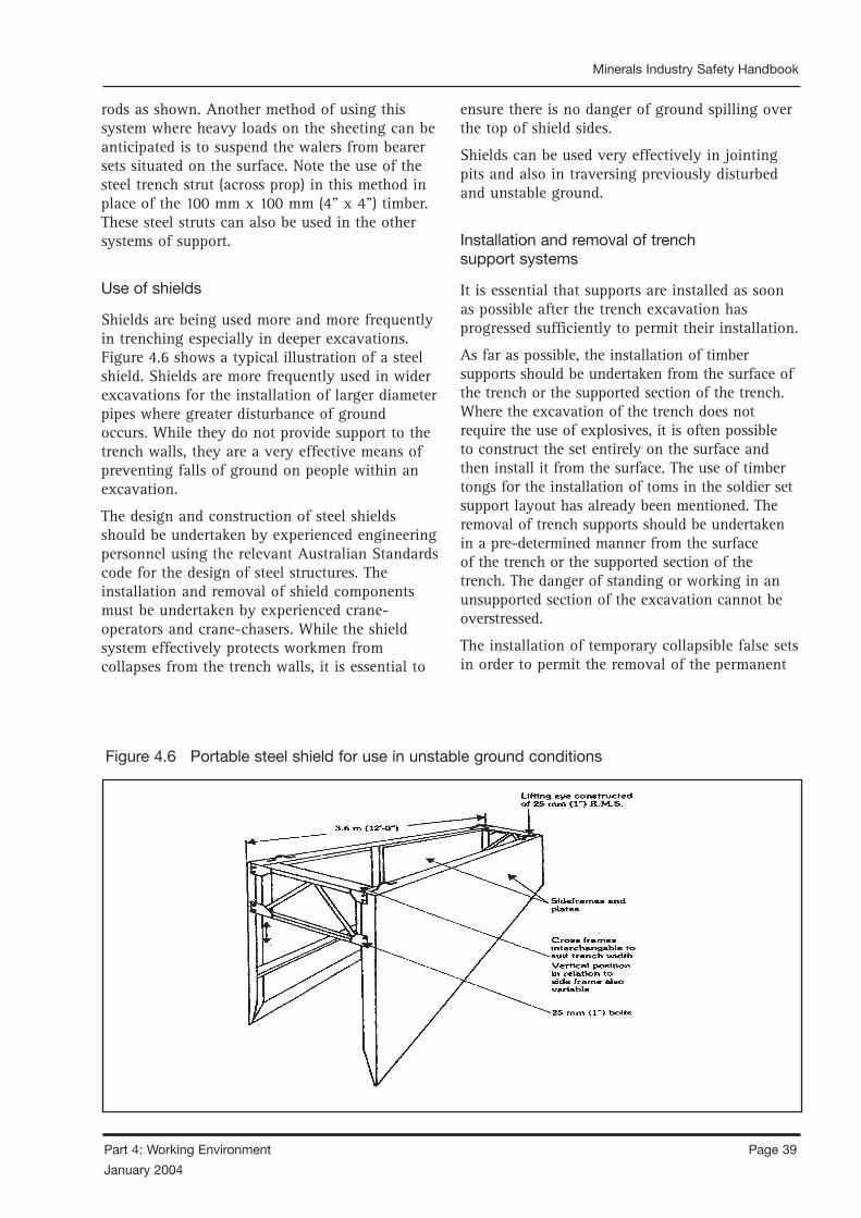
Page 38 Part 4: Working Environment
January 2004
Minerals Industry Safety Handbook
Part 4: Working Environment Page 39
January 2004
Minerals Industry Safety Handbook
rods as shown. Another method of using this system where heavy loads on the sheeting can be anticipated is to suspend the walers from bearer sets situated on the surface. Note the use of the steel trench strut (across prop) in this method in place of the 100 mm x 100 mm (4” x 4”) timber. These steel struts can also be used in the other systems of support.
Use of shields
Shields are being used more and more frequently in trenching especially in deeper excavations. Figure 4.6 shows a typical illustration of a steel shield. Shields are more frequently used in wider excavations for the installation of larger diameter pipes where greater disturbance of ground occurs. While they do not provide support to the trench walls, they are a very effective means of preventing falls of ground on people within an excavation.
The design and construction of steel shields should be undertaken by experienced engineering personnel using the relevant Australian Standards code for the design of steel structures. The installation and removal of shield components must be undertaken by experienced crane-operators and crane-chasers. While the shield system effectively protects workmen from collapses from the trench walls, it is essential to
ensure there is no danger of ground spilling over the top of shield sides.
Shields can be used very effectively in jointing pits and also in traversing previously disturbed and unstable ground.
Installation and removal of trench support systems
It is essential that supports are installed as soon as possible after the trench excavation has progressed sufficiently to permit their installation.
As far as possible, the installation of timber supports should be undertaken from the surface of the trench or the supported section of the trench. Where the excavation of the trench does not require the use of explosives, it is often possible to construct the set entirely on the surface and then install it from the surface. The use of timber tongs for the installation of toms in the soldier set support layout has already been mentioned. The removal of trench supports should be undertaken in a pre-determined manner from the surface of the trench or the supported section of the trench. The danger of standing or working in an unsupported section of the excavation cannot be overstressed.
The installation of temporary collapsible false sets in order to permit the removal of the permanent
Figure 4.6 Portable steel shield for use in unstable ground conditions

Page 40 Part 4: Working Environment
January 2004
Minerals Industry Safety Handbook
Part 4: Working Environment Page 41
January 2004
Minerals Industry Safety Handbook
ones is an extremely useful and safe manner of removing supports. Another very safe method of removing timber supports is to remove the horizontal toms and walers as the backfilling of the trench reaches the level of each set of toms and walers. The vertical sheeting can then be removed when backfilling is completed.
REFERENCE DOCUMENTS
AS 1657 – 1992. Fixed Platforms, Walkways, Stairways and Ladders – Design, Construction and Installation.
AS/NZS 2865 – 2001 Safe Working in a Confined Space.
AS 4368 – 1996 Preparation and Symbols – Mine Plans.
4.3.3 SCAFFOLDING
4.3.3.1 INTRODUCTION
A scaffolder’s ticket may be required, but persons performing this work should be appropriately trained to an equivalent standard, bearing in mind the work involved. State and Territory legislation normally requires such training.
Important questions to ask are attached for guidance. These questions may not be relevant in every situation.
4.3.3.2 USE OF SCAFFOLDS
• Does company policy require that work performed from ladders is kept to a minimum and that scaffolds or other platforms are used wherever possible?
• Has management established adverse weather condition limits for various work activities beyond which work cannot progress? (Examples are high wind velocity and temperature extremes.) How does management insist that these limits are adhered to?
• Are all workers in the vicinity warned to keep clear of scaffolds? (There are dangers both from falling objects and due to mobile machinery knocking the scaffold.)
• Are both operators and supervisors aware of the book A Guide for Scaffolders (AS/NZS 4576–1995) and Stands for Portable Ladders (AS/NZS 1892).
4.3.3.3 SAFE ACCESS AND PROVISION
OF LADDERS
• Do employees know:
– the high and serious incidence of accidents from ladders set in temporary positions and work platforms without safe access?
– that ladders often slide sideways or slip away at the base?
– that scaffolding members are not suitable ladderways and that scaffolding may be overturned by misuse?
– that, when access to formwork is required, ladder access should be provided within the framework so that the scaffold remains stable?
– the best ladder design for different applications? Examples include cantilevered ladders; ladder access tower; (and extension, single and portable Batten) ladders.
– safe ladder angles and placement of lighting for underground vision or night use?
• Do unauthorised personnel know not to interfere with guardrails, toeboards, ladder lashings etc. without contacting the scaffolding supervisor?
• Do operators know the hazards of using metal or wire-reinforced ladders in the vicinity of electrical conductors?
• Do operators know how to check for defective or broken ladders? (Broken or defective ladders should be removed or tagged as dangerous.)
Page 40 Part 4: Working Environment
January 2004
Minerals Industry Safety Handbook
Part 4: Working Environment Page 41
January 2004
Minerals Industry Safety Handbook
4.3.3.4 SUPERVISION
• Are supervisors:
– trained in the hazards associated with the use of scaffolds?
– able to check the use of scaffolds readily and regularly?
– able to have rectified any apparent defect reported to them?
– able to restrict work near the scaffolding? and
– trained for emergencies that might arise?
• Is an erection and dismantling procedure established and followed?
• Are employees directed in the use of ramps, stairs and ladders for access and egress (exit) from work platforms?
• Is jumping from elevated platforms, scaffolding or ladders should be prohibited?
• Are supervisors aware of their responsibility while scaffolders are undergoing training on the job?
• Are guidelines clear about when different scaffolding types are to be used with which the scaffolder may be unfamiliar?
4.3.3.5 PERSONNEL
• Are personnel adequately trained? Do they have any training record?
• Are personnel assessed for their level of skill? The scaffolder should have a thorough knowledge of:
– bends and hitches for cordage and light wire ropes;
– safe working loads of fibre;
– safe working loads of flexible steel wire (FSW) ropes, and safety measures when used as suspension ropes, winch ropes, and lashings on scaffolds;
– safe working loads, which can be supported by timber beams, and cantilevers (or needles);
– the correct way to use an RSJ beam clamp;
– the correct way to use “S” type scaffold hooks;
– the various masses of scaffold planks and timbers in ordinary use;
– the manner of attaching counterweights and securing same;
– safe working loads on mild steel (MS) bolts in tension, for securing cantilevered scaffolds etc;
– the manner in which the mass of the counterweights required on various types of scaffolding is determined;
– how to detect defects in structural timbers, both hardwood and softwood;
– how to examine fibre ropes for defects;
– how to examine wire ropes for defects;
– the correct way to use bulldog grips; and
– the correct usage of ladders, stepladders, and access platforms.
• Are outside personnel given induction training at the mine sufficient to cover any area in which they may be required to work?
• Are certificated personnel given induction and familiarisation training at the mine?
• Is there a recognition that some people cannot work safely and efficiently at heights?
• Do all operators inspect the scaffold before use and report defects to their supervisor?
• Do all operators see that the area below them is clearly marked with signs and barricades if necessary? Have they checked with their supervisor that all workers in the vicinity have been warned to keep clear?
• Are fork lift and Load-Haul-Dump (LHD) and Front-End Loader (FEL) operators who place material on scaffolds required to have a physical examination including assessment of visual acuity, depth perception and hearing loss?
• Are operators able to clearly understand the English language and the use of hand or other signals?
Page 42 Part 4: Working Environment
January 2004
Minerals Industry Safety Handbook
Part 4: Working Environment Page 43
January 2004
Minerals Industry Safety Handbook
4.3.3.6 CONSTRUCTION AND
MAINTENANCE
• Are scaffolds built to comply with applicable codes, including material selection and scaffold design?
• Is there one person who is responsible for erection and dismantling, and who is aware of code requirements?
• Is maximum load considered in the scaffold design and construction so that there is a correct factor of safety? Is overloading of scaffold prohibited?
• Are footings under scaffolds stable and able to bear the load safely?
• Are supports plumb and bracing adequate and checked after mine firings?
• Are scaffold planks cleated on the bottom to prevent slipping or sliding?
• Are scaffolds secure to the structure? Are outriggers used according to manufacturers recommendations?
• Are railings and toeboards installed on all scaffolding? Are scaffold ends closed?
• Is a safe and unobstructed access, such as a walkway, stairs or ladder, provided on all scaffold platforms?
• Do ladders comply with the ladder code?
• Is good housekeeping maintained on scaffolds and their approaches?
• Is each scaffold walkway kept free of ice, oil, spillage and other slippery or loose substances?
• Is particular care taken for the stability of platforms where heavy parts are to be shifted about or heavy strains to be taken?
• Are swing stages or suspended scaffolds erected and used according to applicable standards?
• Is the use of safety belts and separate life lines required when work is done from a suspended scaffold, and are these maintained and tested regularly?
• Are written exemptions from use of safety belts received when working conditions or
experience of operator negate the use of same – for example, experienced riggers on steelwork?
4.3.3.7 MOBILE PLATFORMS
• Are mobile platforms used only for light work?
• Are they kept to a height not exceeding three times the smallest base dimension?
• Is help provided when rolling the platform to a new position?
• Are all persons off the platform when it is moved?
• Are the operators trained so that they will not overextend the levelling jacks?
• Are wheel locks provided to prevent movement when in use?
• Can the platform be located to avoid over-reaching?
• Are guard rails installed at 1 metre above the platform?
• Are toeboards greater than 100 mm in height used and secure?
4.3.3.8 TRESTLE SCAFFOLDS
• Is the platform surface wide enough for comfortable work?
• Do the planks forming its surface project (say, more than 230 mm) beyond the end of the scaffold supports and, if so, what precautions are there to prevent tipping?
• Are adjoining planks cleated to prevent sagging more than the adjacent one(s) to it?
• Is attention paid to the soundness of the planks and trestles, as well as to the foundations?
• Is the use of extension ladders for ladder jack scaffolds prohibited?
Page 42 Part 4: Working Environment
January 2004
Minerals Industry Safety Handbook
Part 4: Working Environment Page 43
January 2004
Minerals Industry Safety Handbook
4.3.3.9 FALLS FROM SCAFFOLDS
• Are openings barricaded?
• Are safety belts and lifelines used when employees are working on unguarded surfaces? Are safety nets used whenever necessary?
• Is all reinforcing steel bent or covered to eliminate impalement if an employee were to fall?
• Are qualified riggers used when there is a danger from falling and safety hats or lifelines are not used?
4.3.3.10 FALLING OBJECTS
• Is work planned so that workers are not working below one another?
• Are workers instructed in safe material handling to prevent objects from falling? Are safety lines used on tools where needed?
• Are nets or shelters used where necessary as protection from falling objects? Are forklift trucks or similar mobile plant equipped with overhead protection?
• Is the wearing of head protection enforced?
• Is work planned to avoid handling material over workers? If a suspended load is moved over a work area, are warning signals sounded so workers will keep out from under loads?
• Is all lifting and hoisting equipment regularly inspected and maintained in accordance with manufacturer’s recommendations and applicable standards?
• Is a rope used to haul tool boxes and equipment to the platform? If fibre ropes are used, are they checked for damage from sparks, heat, acid or other chemicals?
• Are special precautions taken when drilling or welding to ensure that swarf, sparks, and molten slag do not drop on people below? Can a fire blanket be used below the platform to prevent falling of sparks and metal?
• Are oxyacetylene bottles, fuel, and explosives placed so that hot or flammable objects cannot land on them?
• Are employees instructed to secure a piece of timber or metal before it is cut? If pipes are being cut, is there a potential for the securing slings or ties to slip and for the pipes to fall out of control?
4.3.3.11 EMERGENCY CARE
• Are supervisors and other selected employees trained in critical emergency care techniques that might be necessary in the event of a serious injury?
• Are rescue procedures for persons who may be electrified or suffering electric shock understood?
• Are first aid supplies readily available and their location known?
• Do supervisors and other staff know how to contact the nearest ambulance or emergency service. In case of a serious injury, is that contact facility readily available?
REFERENCE DOCUMENTS
AS 2243 – 1990 to 2002 Safety in Laboratories. [Note: There are 10 parts to this Standard.]
AS2865 – 1995 Safe Working in a Confined Space.
AS2987 – 1987 General Conditions of Contract for the Supply of Equipment with or without Installation.
ASNZS 4576 – 1995 Guidelines for Scaffolding.
AS1892 – Portable Ladders.
AS1657 Fixed Platform, Walkways, Stairways and Ladders.
4.3.4 BUILDINGS AND STRUCTURES
4.3.4.1 INTRODUCTION
When providing necessary and relevant hygiene and health facilities at mines, managers should consider:

Page 44 Part 4: Working Environment
January 2004
Minerals Industry Safety Handbook
Part 4: Working Environment Page 45
January 2004
Minerals Industry Safety Handbook
• sanitation and hygiene needs, including:
– an adequate supply of potable water (both above and below ground and cooled where necessary);
– provision to maintain cleanliness and sanitation (including eradication of vermin);
– clean and sufficient toilet and washing facilities at surface and underground (where necessary, male and female employees should have separate facilities);
– sufficient hand basins;
– regular checks to stop pollution of work sites and misuse or fouling of toilets;
– sufficient crib rooms or dining areas (both above and below ground as appropriate at every mine);
– sufficient change houses, depending on the size, scale and nature of the mine;
– drainage of stagnant water (note: noxious gases may be produced when draining water);
– checks for waste timber and decaying wood in underground sites;
– regular disposal of debris, refuse and other waste; and
– sheltered reception areas for people entering or leaving the mine;
• mine lighting;
• first aid precautions; and
• medical matters.
4.3.4.2 SUPPLY OF POTABLE WATER
Water should meet standards set out in Australian Drinking Water Guidelines (1996) by NHMRC and ARMCANZ.
Water should be:
• accessible to employees;
• clean;
• dispensed at clean and hygienic locations marked by signs; and
• below 24°C.
Water used for industrial processes which is unfit for drinking should be marked “unfit”. Staff working away from main water supplies should have access to water in clean containers.
4.3.4.3 TOILET AND WASHING FACILITIES
Above ground facilities should be conveniently located with:
• adequate toilets and urinals (as a guide, one toilet and urinal for every twenty-five male staff and one toilet for every nine female staff);
• hand towels or hand dryers; and
• adequate heat, light and ventilation.
Toilets on the surface of a mine should have:
• flushing water;
• individual compartments with locking doors
• walls and floors made of easy-to-clean materials;
• seats and toilet paper;
• clothes hook and lighting; and
• be kept clean and hygienic and with all waste products removed regularly.
Toilets at underground mines should be at many locations and accessible on foot unless:
• workings are close to the surface; or
• a conveyance is available to take staff to underground toilets or to the surface.
Toilets in underground mines should be well ventilated and near the main work site to serve the largest number of staff. They should have:
• floors of concrete or other impervious material;
• screens for privacy;
• regular maintenance, cleaning and waste removal;
• toilet paper; and
• sinks or hand basins.
Page 44 Part 4: Working Environment
January 2004
Minerals Industry Safety Handbook
Part 4: Working Environment Page 45
January 2004
Minerals Industry Safety Handbook
4.3.4.4 CRIB ROOMS
All mines should have clean, well-lit and ventilated crib rooms and eating areas. Crib rooms should have refuse bins, a sink, tables, chairs and appliances to store food, heat food and boil water. They should also have supplies of hot and cold drinking water, insect repellents or traps, and be close to toilet and washing facilities.
Management should encourage staff to put rubbish, waste food and paper in bins that should have well-fitted covers. Empty bins in underground crib rooms regularly and take rubbish to the surface daily. Clean the refuse area in crib rooms daily.
4.3.4.5 CHANGE HOUSES
The design of change rooms should consider the following:
• lighting, heating and ventilation;
• floors that will not rot and are easy to clean;
• proper drainage;
• tiled walls to keep out moisture;
• passageways at least 1 m wide;
• be near mine entrances;
• have facilities to protect people from the weather when travelling from the mine entrance to the change house;
• have lockers for each underground employee; and
• have benches.
Change rooms should be designed to include:
• adequate floor space per person using the change house during a shift;
• an ample supply of clean hot and cold water, hand basins and showers;
• ventilation, lighting, facilities to dry and store clothes;
• separate areas for clean and working clothes;
• heaters and/or air conditioners; and
• separate facilities for males and females.
Mine operators should set out guidelines and rosters for cleaning change houses.
4.3.5 CONFINED SPACES
The AS/NZS 2865 – 2001 Safe Working in a Confined Space provides comprehensive information to use in confined spaces.
A more comprehensive discussion of this topic is provided in Part 5 Equipment and Machinery, Section 5.1.5.
4.3.5.1 CHECKLIST
Below is a checklist of considerations before entry to confined spaces takes place:
• Are confined spaces thoroughly emptied of any corrosive or hazardous substances, such as acids or caustics, before entry?
• Are all lines to a confined space, containing inert, toxic, flammable, or corrosive materials valved off and blanked or disconnected and separated before entry?
• Are all impellers, agitators, or other moving parts and equipment inside confined spaces locked–out if they present a hazard?
• Is either natural or mechanical ventilation provided prior to confined space entry?
• Are appropriate atmospheric test performed to check for oxygen deficiency, toxic substances and explosive concentrations in the confined space before entry?
• Is adequate illumination provided for the work to be performed in the confined space?
• Is the atmosphere inside the confined space frequently tested or continuously monitored during conduct of work?
• Is there an assigned safety standby employee outside of the confined space, when required whose sole responsibility is to watch the work in progress, sound an alarm if necessary and render assistance?
• Is the standby employee appropriately trained and equipped to handle an emergency?
• Is the standby employee or other employees prohibited from entering the confined space without lifelines and respiratory equipment if there is any question as to the cause of an emergency?

Page 46 Part 4: Working Environment
January 2004
Minerals Industry Safety Handbook
Part 4: Working Environment Page 47
January 2004
Minerals Industry Safety Handbook
• Is approved respiratory equipment required if the atmosphere inside the confined space cannot be made acceptable?
• Is all portable electrical equipment used inside confined spaces either grounded and insulated, or equipped with ground fault protection?
• Before gas welding or burning is started in a confined space, are hoses checked for leaks, compressed gas bottles forbidden inside of the confined space, torches lightly only outside of the confined area and the confined area tested for an explosive atmosphere each time before a lighted torch is to be taken into the confined space?
• If employees will be using oxygen–consuming equipment, such as salamanders, torches and furnaces, in a confined space, is sufficient air provided to assure combustion without reducing the oxygen concentration of the atmosphere below 19.5% by volume?
• Whenever combustion-type equipment is used in a confined space, are provisions made to ensure the exhaust gases are vented outside of the enclosure?
• Is each confined space checked for decaying vegetation or animal matter which may produce methane?
• Is the confined space checked for possible industrial waste which could contain toxic properties?
• If the confined space is below the ground and near areas where motor vehicles will be operating, is it possible for vehicle exhaust or carbon monoxide to enter the space?
WARNING: Many people have died when they have entered a confined space to rescue a person who has collapsed. Avoid this by ensuring that harnesses and lifelines are used. No person should be allowed to enter any confined space without means of life support and without rescuers standing by.
REFERENCE DOCUMENTS
Boral OH&S Manual, Boral.
AS/NZS 2865 – 2001 Safe Working in a Confined Space.
Occupational Health and Safety Manual, Pioneer Concrete NSW P/L.
OSHA’s Self – Inspection Checklists, Confined Spaces Safety Information Com, OSHA.
4.3.6 WORKING AT HEIGHTS
Employers have an obligation to ensure workplace health and safety where there is a risk of a person falling from any height.
4.3.6.1 RISK MANAGEMENT
Risk management is the process of finding out what can cause an injury such as falls from heights deciding what could happen as a result (injury to persons at or near a workplace), and doing something about it.
The steps of risk management are:
• identify the hazards to workplace health and safety arising from construction activities;
• assess the risks;
• determine and implement control measures to eliminate or reduce the risks; and
• monitor and review the effectiveness of the control measures.
Hazard identification
Prior to commencing work, all hazards related to falls from heights should be identified. There are a number of ways to identify potential sources of injury. The selection of the appropriate procedure will depend on the type of work processes and hazards involved. Methods of identifying hazards include:
• consultation with workers is one of the easiest and most effective means of identifying hazards. Workers are usually aware of what can go wrong and why, based on their experience with a job; and
• specialist practitioners and representatives of industry associations, unions and government bodies may be of assistance in gathering health and safety information relevant to falls from heights.
Page 46 Part 4: Working Environment
January 2004
Minerals Industry Safety Handbook
Part 4: Working Environment Page 47
January 2004
Minerals Industry Safety Handbook
Factors which can cause a person to fall include:
• sudden acceleration or deceleration;
• moving from one surface to another;
• inadequate capability of the surface supporting a load;
• openings or holes that are not identified or protected;
• open edges are not protected;
• change of levels;
• loss of hand grip;
• slippery surfaces (surfaces are wet, polished or oily);
• unsuitable footwear;
• equipment, tools, rubbish obstructing work areas;
• incorrect use of ladders;
• catching of clothing;
• moving surfaces;
• unsatisfactory lighting;
• bad weather conditions (for example, heavy rain or wind);
• struck by moving or falling object; and
• fall-arrest systems and devices are not provided or are used incorrectly.
Risk assessment
Risk assessment allows appropriate control measures to be developed. Once hazards have been identified, they should be assessed in terms of their potential to do harm. To assess risk, consideration should be given to:
• the likelihood that harm will occur; and
• the severity of the harm should it occur.
Various techniques can be used to carry out a risk assessment. The risk assessment calculator is an example of one technique which can be used to assess risk.
Factors to consider when assessing the likelihood and severity of risk include:
• potential sources of injury and illness;
• number of people who may be exposed;
• location of the work area;
• location of access routes;
• type of work to be carried out;
• work practices in use;
• scheduling of work;
• type of plant, machinery and equipment to be used; and
• training and experience of persons carrying out the work.
Risk control
Risk control is the process of eliminating or reducing the risk factors. Control measures should be chosen and implemented to eliminate or reduce the risks as far as possible. When deciding on the most appropriate measures to use, practicability and acceptance of the control measures should be considered.
The following control measures are listed in order of the most effective way of managing the risk of injury from falls from heights at a workplace.
• Eliminate the hazard.
• Minimise the risk:
– substitute the material or process with a less hazardous one;
– modify the system of work or equipment; and
– isolate the hazard.
• Provide backup controls:
– adopt administrative controls so the time or conditions of exposure to the risk is reduced; and
– use personal protective equipment.
4.3.6.2 CONTROL MEASURES
The control measures to protect a person from the risk of falling from a height should be in place before any work at the height starts. For example ensuring working platforms are in place before formwork is erected.
Several control measures are available to protect persons from the risk of falling from a height when carrying out work at that height. In some circumstances, more than one control measure may be necessary. The three levels of control
Page 48 Part 4: Working Environment
January 2004
Minerals Industry Safety Handbook
Part 4: Working Environment Page 49
January 2004
Minerals Industry Safety Handbook
measures, in order of preference, are:
• erecting a physical barrier;
• providing personal fall protection; and
• measures to catch a person after they have fallen.
Physical barriers
The aim should be to prevent a person from falling from a height. This is achieved by implementing control measures which provide a physical barrier.
Preventing a person from falling from a height is the preferred control option, as other measures will not always prevent the person from being injured. For example:
• fall arrest systems may prevent a person from falling to another working surface. However, the person using the system may suffer an injury as a result of the load placed on the person’s body by the fall arrest harness when the fall is arrested; and
• a person may lose their balance and fall from a working platform and be caught by a catch net. However, because the fall was unexpected the person may suffer an injury through landing in the catch net awkwardly.
Some of the control measures to prevent persons from falling are:
• edge protection systems;
• fall protection covers; and
• working platforms.
Edge protection systems
An edge protection system is a barrier which is erected around the edge of a building or structure of penetration.
Guardrailing
Guardrailing is a protective barrier attached directly to a building or structure by posts. Guardrails should be used on the edge of a working platform, walkway, stairway, ramp or landing and be able to withstand the impact of a person falling against it. The guardrail should run parallel to the working surface and be not further than 100 mm outside the edge of the working surface. Guardrails used for working platforms, walkways, stairways, ramps or
landings should be between 900 mm and 1100 mm above the working surface.
Guardrailing should not be used without a midrail. A midrail is a structural member which should be secured midway between the guardrail and the working surface and be able to withstand the impact of a person falling against it. The midrail should also run parallel to the working surface and be not further then 100 mm outside the edge of the working surface.
A toeboard should be used in conjunction with guardrails and midrails to prevent a person from falling under the guardrailing. Toeboards may be fully sheeted with timber or metal or made from mesh. They should be secured adjacent to the work surface and extend a minimum of 150 mm above the work surface.
4.3.6.3 FALL PROTECTION COVERS
All holes and openings, other than lift shafts and stairwells, should be protected to prevent persons falling through the holes or openings. A fall protection cover is a protective structure placed over holes and openings to prevent persons from falling through the holes or openings. A cover should be capable of supporting the impact of a person falling onto it. Fall protection covers are usually sheeted with:
• solid sheeting (timber, plywood or metal); and
• mesh.
Any holes or openings covered with wire mesh should not be used as a working platform. All covers should be securely fixed around the hole. Signs should also be attached to the cover to warn person that there is a hole underneath.
4.3.6.4 WORKING PLATFORMS
A working platform provides a permanent or temporary surface for persons to carry out work. The platform should be secured against uplift or displacement to a structure and be installed with edge protection systems. The area of the working platform should be of a size and strength to safely support tools, materials and persons who may be working on it.

Page 48 Part 4: Working Environment
January 2004
Minerals Industry Safety Handbook
Part 4: Working Environment Page 49
January 2004
Minerals Industry Safety Handbook
When using a working platform:
• persons should not use platforms supported by a crane or hoist which is designed for the carrying of materials only;
• a person’s body should not protrude from the confines of the working platform while it is moving;
• working platforms should not be used in wind conditions which may result in the working platform becoming unstable; for example, a boatswain’s chair;
• working platforms should not be less than 450 mm in width or length;
• plant used to support working platforms should be used in accordance with the designer and/or manufacturer’s instructions; for example, an elevated working platform;
Different types of working platforms that can be used include:
• Working Platforms on Scaffold: consist of planks or prefabricated platforms secured against uplift or displacement; and
• Elevating Work Platform; consist of platform surrounded by an edge protection system. The elevating work platform is used to position person at work areas. Different types of elevating work platforms include telescopic, scissor, boom, articulated platforms or any combination of these.
4.3.6.5 PERSONAL FALL PROTECTION
Personal fall-protection systems of work, including equipment, which secure a person to a building or structure. These systems should only be used where:
• it is not possible to work within the confines of a working platform or to provide other forms of fall protection such as guardrailing; or
• it is used in conjunction with other measures.
The use of these systems requires the active involvement of all person to ensure the equipment is worn, attached and used in the correct way.
Where no other forms of fall protection can be used, personal fall protection systems should be used to:
• minimise the risk of a person from falling from a height (travel restriction devices); and
• minimise the risk of injury to a person after a person has fallen from a height (fall arrest systems).
Figure 4.7 Fall-protection prevention system
Travel restriction devices
Personal fall-protection systems which do not allow a person to get into a falling situation are preferred over those which arrest a person once the person has fallen. These are travel restriction devices where a person is tethered to an eyebolt or another suitable anchorage point to restrain a person from reaching an unprotected edge. The anchorage points should be capable of taking the load. Personal fall-protection devices which restrict travel include:
• industrial rope access systems; and
• fall-prevention systems.
An industrial rope access system is a twin rope system used to provide access to a work area. A work positioning harness or seat is attached to one rope and a fall arrest harness is attached to the other rope. The system should be used in accordance with the designer’s and/or the manufacturer’s instructions.
A fall-prevention system is a restraint belt or work positioning harness connected to a restraint line and attached to a fall-prevention static line or an anchorage point which prevent a person getting into a situation where they could fall. The following points describe the components of a fall-prevention system:
• a restraint belt, or work positioning harness is worn by a person connected to a restraint

Page 50 Part 4: Working Environment
January 2004
Minerals Industry Safety Handbook
Part 4: Working Environment Page 51
January 2004
Minerals Industry Safety Handbook
line to restrict the horizontal distance of the wearer; and
• a fall-prevention static line is a horizontal line connected to a fixed anchorage point, to which a restraint line is attached. An anchorage point of a fall-prevention system should be positioned to ensure that the restraint line does not allow the person wearing the system to free-fall.
4.3.6.6 METHODS OF FALL ARREST
The function of a fall-arrest system is to arrest a person’s fall to minimise injury if a fall occurs.
Fall-arrest systems may be used in conjunction with higher levels of control measures, such as perimeter guardrails or scaffolding. Where it is not practicable to provide higher levels of control, fall-arrest systems may be used.
When fall-arrest systems are used in a system of work, they should be evaluated to ensure that they are effective and safe, and that no new hazards are created (such as trip hazards or persons movements being restricted).
Fall-arrest systems
Industrial fall-arrest systems and devices are designated to arrest an accidental fall, and consist of some or all of the following:
• anchorage points;
• energy absorber;
• fall-arrest device;
• fall-arrest harness (safety harness);
• inertia reel;
• lanyard;
• lanyard assembly; and
• static line.
Fall-arrest devices such as harnesses and lanyard can be used as travel restriction systems to prevent workers moving from safe to unsafe areas on the roof. Industrial fall-arrest systems and devices should be used in accordance with the manufacturer’s instructions.
The various parts of fall-arrest systems and harnesses should be compatible. It is therefore essential for the user to check that
all components are compatible and fit safely together.
Components of fall-arrest systems and harnesses from different manufacturers should not be mixed as they may be unsafe when used together and can lead to failure of the fall-arrest system.
Harnesses and lanyards
Fall-arrest systems should be designed so that the safety line is as short as possible. The shorter the free-fall distance, the less chance a person has of falling into objects or being injured.
Full-body harnesses parachute type, complying with AS/NZS 1891 Industrial Fall Arrest Systems and Devices should be used. The harness should be connected to the lanyard or line at the top dorsal position. If a line and rope grab device is used on steeply sloping roofs, the user needs the device in front in order to manually operate the mechanism. In this case, the user should consider a harness with a front D-ring connection.
Note: Waist-type belts must not be used for work at heights, or where any free-fall may be involved.
Lanyards used should have a minimum of slack in the lanyard or safety line between the person and attachment to the anchorage.
Lanyards used should have minimum tensile strength of 15 kN (approx 1500 kg) and should comply with AS/NZS 1891 Fall – Arrest Systems and Devices.
Energy absorbers should be used as part of the lanyard assembly to reduce shock to the body and anchorage point by absorbing some of the fall energy.
Figure 4.8 Harness

Page 50 Part 4: Working Environment
January 2004
Minerals Industry Safety Handbook
Part 4: Working Environment Page 51
January 2004
Minerals Industry Safety HandbookMinerals Industry Safety Handbook
The use of lanyards in conjunction with inertia reels should be avoided as they could reduce the effectiveness of the inertia reel. Where the use of a short lanyard is necessary for ease of connection to the rear harness connection point of an inertia reel, it should be no greater than 450 mm in length.
Persons using a fall-arrest system must be attached to the system at all times where there is a risk of a fall. If transferring from one anchorage or secure point to another, a second lanyard attached to the safety harness may be used. Connect the second lanyard to the anchorage or secure point before disconnecting the first.
Do not connect snaphooks to each other. Persons wearing fall-arrest systems should not work alone. It is vital that before the commencement of working at heights that all persons working in the area understand the emergency rescue procedures in the event of a fall. A risk assessment associated with the rescue method should also be conducted.
Inertia reel systems
Inertia reel systems can be used to prevent falls where persons are required to carry out their work near an unprotected edge (see diagram). They should comply with AS/NZS 1891 Fall – Arrest Systems and Devices.
Inertia reels are not designed for continuous support but become effective in the event of a fall. They should not be used as working supports
by locking the system and allowing it to support the user during normal work. Inertia reels may be less effective for certain applications such as stopping a person falling down the inclined surface of a pitched roof.
Static lines
The installation of safety line systems should be carried out in accordance with the manufacturer’s or designer’s specifications by a competent person.
The static line to be used should be located as high as practicable. It is dangerous to work above the static line as the person could fall more than 2.4 metres.
Static lines should have a minimum tensile strength of 22 kN (approx 2.2 tonne) and their anchorages should have a design capacity of 22 kN (approx 2.2 tonne). Intermediate supports for static lines should not exceed 6.0 metre spacing unless specifically designed to do so.
Pendulum effect
The pendulum effect is a potential hazard associated with the use of fall-arrest systems. It can occur during swing down and swing back. The pendulum effect may also occur within the interior of the roof if the positioning of the inertia reel allows for a significant length of unsupported line connected to the user.
Figure 4.9 Inertia reel system
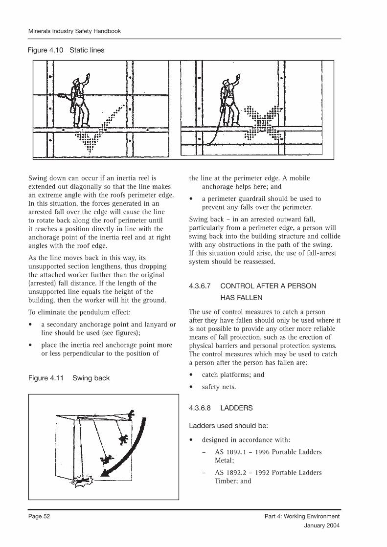
Page 52 Part 4: Working Environment
January 2004
Minerals Industry Safety Handbook
Part 4: Working Environment Page 53
January 2004
Minerals Industry Safety Handbook
Swing down can occur if an inertia reel is extended out diagonally so that the line makes an extreme angle with the roofs perimeter edge. In this situation, the forces generated in an arrested fall over the edge will cause the line to rotate back along the roof perimeter until it reaches a position directly in line with the anchorage point of the inertia reel and at right angles with the roof edge.
As the line moves back in this way, its unsupported section lengthens, thus dropping the attached worker further than the original (arrested) fall distance. If the length of the unsupported line equals the height of the building, then the worker will hit the ground.
To eliminate the pendulum effect:
• a secondary anchorage point and lanyard or line should be used (see figures);
• place the inertia reel anchorage point more or less perpendicular to the position of
the line at the perimeter edge. A mobile anchorage helps here; and
• a perimeter guardrail should be used to prevent any falls over the perimeter.
Swing back – in an arrested outward fall, particularly from a perimeter edge, a person will swing back into the building structure and collide with any obstructions in the path of the swing. If this situation could arise, the use of fall-arrest system should be reassessed.
4.3.6.7 CONTROL AFTER A PERSON
HAS FALLEN
The use of control measures to catch a person after they have fallen should only be used where it is not possible to provide any other more reliable means of fall protection, such as the erection of physical barriers and personal protection systems. The control measures which may be used to catch a person after the person has fallen are:
• catch platforms; and
• safety nets.
4.3.6.8 LADDERS
Ladders used should be:
• designed in accordance with:
– AS 1892.1 – 1996 Portable Ladders Metal;
– AS 1892.2 – 1992 Portable Ladders Timber; and
Figure 4.11 Swing back
Figure 4.10 Static lines
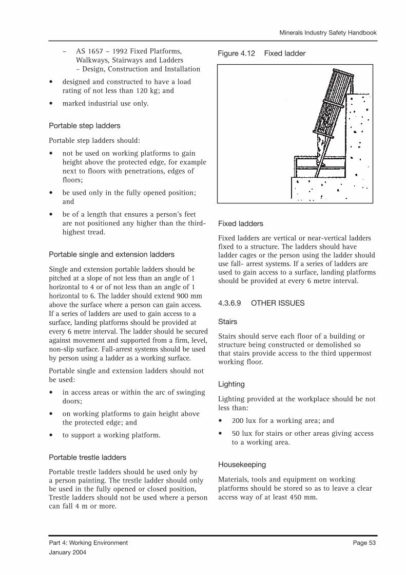
Page 52 Part 4: Working Environment
January 2004
Minerals Industry Safety Handbook
Part 4: Working Environment Page 53
January 2004
Minerals Industry Safety Handbook
– AS 1657 – 1992 Fixed Platforms, Walkways, Stairways and Ladders – Design, Construction and Installation
• designed and constructed to have a load rating of not less than 120 kg; and
• marked industrial use only.
Portable step ladders
Portable step ladders should:
• not be used on working platforms to gain height above the protected edge, for example next to floors with penetrations, edges of floors;
• be used only in the fully opened position; and
• be of a length that ensures a person’s feet are not positioned any higher than the third- highest tread.
Portable single and extension ladders
Single and extension portable ladders should be pitched at a slope of not less than an angle of 1 horizontal to 4 or of not less than an angle of 1 horizontal to 6. The ladder should extend 900 mm above the surface where a person can gain access. If a series of ladders are used to gain access to a surface, landing platforms should be provided at every 6 metre interval. The ladder should be secured against movement and supported from a firm, level, non-slip surface. Fall-arrest systems should be used by person using a ladder as a working surface.
Portable single and extension ladders should not be used:
• in access areas or within the arc of swinging doors;
• on working platforms to gain height above the protected edge; and
• to support a working platform.
Portable trestle ladders
Portable trestle ladders should be used only by a person painting. The trestle ladder should only be used in the fully opened or closed position, Trestle ladders should not be used where a person can fall 4 m or more.
Fixed ladders
Fixed ladders are vertical or near-vertical ladders fixed to a structure. The ladders should have ladder cages or the person using the ladder should use fall- arrest systems. If a series of ladders are used to gain access to a surface, landing platforms should be provided at every 6 metre interval.
4.3.6.9 OTHER ISSUES
Stairs
Stairs should serve each floor of a building or structure being constructed or demolished so that stairs provide access to the third uppermost working floor.
Lighting
Lighting provided at the workplace should be not less than:
• 200 lux for a working area; and
• 50 lux for stairs or other areas giving access to a working area.
Housekeeping
Materials, tools and equipment on working platforms should be stored so as to leave a clear access way of at least 450 mm.
Figure 4.12 Fixed ladder

Page 54 Part 4: Working Environment
January 2004
Minerals Industry Safety Handbook
Part 4: Working Environment Page 55
January 2004
Minerals Industry Safety Handbook
Access
Consideration of exposure to the weather should be given when establishing the area for an access way. For example, rain may make surfaces slippery or strong winds may cause loss of balance.
Warning signs
Warning signs should be erected to warn persons of the risk of falling from a height. The signs should be positioned where they will be clearly visible to persons working in the area.
REFERENCE DOCUMENTS
Construction II – Frequently Asked Questions About Construction Matter, Queensland Government, Workplace Health and Safety.
Workplace Health and Safety (Falls From Heights) Advisory Standard 1996, Version 3, May 1998.
ISBN 0724276793, Queensland Government, Workplace Health and Safety.
Pioneer Employee Handbook, Pioneer.
Safety Standard for Fall Protection in the Construction Industry, Occupational Safety and Health Administration, US Department of Labor.
Code of Practice for Working at Heights, Workplace Standards, Tasmania.
Australian Standards
AS 1657 – 1992 Fixed Platforms, Walkways, Stairways and Ladders – Design, Construction and Installation
AS/NZS 1891 – Industrial Fall – Arrest Systems and Devices
AS/NZS 1892 – Portable ladders
Part 1 – Metal
Part 2 – Timber
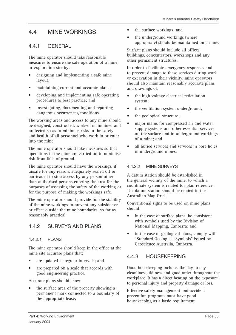
Page 54 Part 4: Working Environment
January 2004
Minerals Industry Safety Handbook
Part 4: Working Environment Page 55
January 2004
Minerals Industry Safety Handbook
4.4 MINE WORKINGS
4.4.1 GENERAL
The mine operator should take reasonable measures to ensure the safe operation of a mine or exploration site by:
• designing and implementing a safe mine layout;
• maintaining current and accurate plans;
• developing and implementing safe operating procedures to best practice; and
• investigating, documenting and reporting dangerous occurrences/conditions.
The working areas and access to any mine should be designed, constructed, worked, maintained and protected so as to minimise risks to the safety and health of all personnel who work in or enter into the mine.
The mine operator should take measures so that operations in the mine are carried on to minimise risk from falls of ground.
The mine operator should have the workings, if unsafe for any reason, adequately sealed off or barricaded to stop access by any person other than authorised persons entering the area for the purposes of assessing the safety of the working or for the purpose of making the workings safe.
The mine operator should provide for the stability of the mine workings to prevent any subsidence or effect outside the mine boundaries, so far as reasonably practical.
4.4.2 SURVEYS AND PLANS
4.4.2.1 PLANS
The mine operator should keep in the office at the mine site accurate plans that:
• are updated at regular intervals; and
• are prepared on a scale that accords with good engineering practice.
Accurate plans should show:
• the surface area of the property showing a permanent mark connected to a boundary of the appropriate lease;
• the surface workings; and
• the underground workings (where appropriate) should be maintained on a mine.
Surface plans should include all offices, buildings, concentrators, workshops and any other permanent structures.
In order to facilitate emergency responses and to prevent damage to these services during work or excavation in their vicinity, mine operators should also maintain reasonably accurate plans and drawings of:
• the high voltage electrical reticulation system;
• the ventilation system underground;
• the geological structure;
• major mains for compressed air and water supply systems and other essential services on the surface and in underground workings of a mine; and
• all buried services and services in bore holes in underground mines.
4.4.2.2 MINE SURVEYS
A datum station should be established in the general vicinity of the mine, to which a coordinate system is related for plan reference. The datum station should be related to the Australian Map Grid.
Conventional signs to be used on mine plans should:
• in the case of surface plans, be consistent with symbols used by the Division of National Mapping, Canberra; and
• in the case of geological plans, comply with “Standard Geological Symbols” issued by Geoscience Australia, Canberra.
4.4.3 HOUSEKEEPING
Good housekeeping includes the day to day cleanliness, tidiness and good order throughout the workplace. It has a direct bearing on the exposure to personal injury and property damage or loss.
Effective safety management and accident prevention programs must have good housekeeping as a basic requirement.

Page 56 Part 4: Working Environment
January 2004
Minerals Industry Safety Handbook
Part 4: Working Environment Page 57
January 2004
Minerals Industry Safety Handbook
Good housekeeping cannot be left to the unplanned activities of the persons employed, but incorporated into each task rather than an extra to it, and time allocated accordingly.
The standards of housekeeping can be a measure of the level of safety sophistication which exists at an operation.
4.4.3.1 DUST AND DIRT REMOVAL
In some jobs, enclosures and exhaust ventilation systems may fail to collect dust, dirt and chips adequately. Vacuum cleaners are suitable for removing light dust and dirt. Industrial models have special fittings for cleaning walls, ceilings, ledges, machinery and other hard-to-reach places where dust and dirt may accumulate.
Dampening floors or using sweeping compounds before sweeping reduces the amount of airborne dust. The dust and grime that collect in places like shelves, piping, conduits, light fixtures, reflectors, windows, cupboards and lockers may require manual cleaning. Special-purpose vacuums are useful for removing hazardous substances. For example, vacuum cleaners fitted with HEPA (high efficiency particulate air) filters may be used to capture fine particles of asbestos or fibreglass.
Compressed air should not be used for removing dust, dirt or chips from equipment or work surfaces, including laboratories and vehicle cabs.
4.4.3.2 EMPLOYEE FACILITIES
Employee facilities need to be adequate, clean and well maintained. Lockers are necessary for storing employees’ personal belongings. Washroom facilities require cleaning once or more each shift. They also need to have a good supply of soap, towels plus disinfectants, if needed.
If workers are using hazardous materials, employees’ facilities should provide special precautions such as showers, washing facilities and change rooms. Some facilities may require two locker rooms with showers between. Using double locker rooms allows workers to shower off workplace contaminants and prevents them from contaminating their “street clothes” by keeping their work clothes separated from the clothing that they wear home.
Smoking, eating or drinking in the work area should be prohibited where toxic materials are handled. The eating area should be separate from the work area and should be cleaned properly each shift.
4.4.3.3 SURFACES
Floors:
Poor floor conditions are a leading cause of accidents, so cleaning up spilled oil and other liquids at once is important. Allowing chips and dust to accumulate can also cause accidents. Trapping chips, shavings and dust before they reach the floor or cleaning them up regularly can prevent their accumulation. Areas that cannot be cleaned continuously, such as entrance ways, should have anti-slip flooring. Keeping floors in good order means replacing worn, ripped, or damaged flooring that poses a tripping hazard.
Walls:
Light-coloured walls reflect light while dirty or dark-coloured walls absorb light. Contrasting colours warn of physical hazards and mark obstructions such as pillars. Paint can highlight railings, guards and other safety equipment, but should never be used as a substitute for guarding. The program should outline the regulations and standards for colours.
4.4.3.4 MAINTAIN LIGHT FIXTURES
Dirty light fixtures reduce essential light levels. Clean light fixtures can improve lighting efficiency significantly.
4.4.3.5 AISLES AND STAIRWAYS
Aisles should be wide enough to accommodate people and vehicles comfortably and safely. Aisle space allows for the movement of people, products and materials. Warning signs and mirrors can improve sight-lines in blind corners. Arranging aisles properly encourages people to use them so that they do not take shortcuts through hazardous areas.
Keeping aisles and stairways clear is important. They should not be used for temporary

Page 56 Part 4: Working Environment
January 2004
Minerals Industry Safety Handbook
Part 4: Working Environment Page 57
January 2004
Minerals Industry Safety Handbook
“overflow” or “bottleneck” storage. Stairways and aisles also require adequate lighting.
4.4.3.6 SPILL CONTROL
The best way to control spills is to stop them before they happen. Regularly cleaning and maintaining machines and equipment is one way. Another is to use drip pans and guards where possible spills might occur. When spills do occur, it is important to clean them up immediately. Absorbent materials are useful for wiping up greasy, oily or other liquid spills. Used absorbents must be disposed of properly and safely.
4.4.3.7 TOOLS AND EQUIPMENT
Tool housekeeping is very important, whether in the tool room, on the rack, in the yard, or on the bench. Tools require suitable fixtures with marked locations to provide orderly arrangement, both in the tool room and near the work bench. Returning them promptly after use reduces the chance of being misplaced or lost. Employees should regularly inspect, clean and repair all tools and take any damaged or worn tools out of service.
4.4.3.8 MAINTENANCE
The maintenance of buildings and equipment may be the most important element of good housekeeping. Maintenance involves keeping buildings, equipment and machinery in a safe, efficient working order and in good repair. This includes maintaining sanitary facilities and regularly painting and cleaning walls. Broken windows, damaged doors, defective plumbing and broken floor surfaces can make a workplace look neglected; these conditions can cause accidents and affect work practices.
It is important to replace or fix broken or damaged items as quickly as possible. A good maintenance program provides for the inspection, maintenance, upkeep and repair of tools, equipment, machines and processes.
4.4.3.9 WASTE DISPOSAL
The regular collection, grading and sorting of scrap contribute to good housekeeping practices. It also makes it possible to separate materials
that can be recycled from those going to waste disposal facilities.
Allowing material to build up on the floor wastes time and energy since additional time is required for cleaning it up. Placing scrap containers near where the waste is produced encourages orderly waste disposal and makes collection easier. All waste receptacles should be clearly labelled (eg recyclable glass, plastic, scrap metal etc).
4.4.3.10 STORAGE
Good organisation of stored materials is essential for overcoming material storage problems whether on a temporary or permanent basis. There will also be fewer strain injuries if the amount of handling is reduced, especially if less manual materials handling is required. The location of the stockpiles should not interfere with work but they should still be readily available when required. Stored materials should allow at least one metre of clear space under sprinkler heads.
Stacking cartons and drums on firm foundation and cross tying them, where necessary, reduces the chance of their movement. Stored materials should not obstruct aisles, stairs, exits, fire equipment, emergency eyewash fountains, emergency showers, or first aid stations. All storage areas should be clearly marked.
Flammable, combustible, toxic and other hazardous materials should be stored in approved containers in designated areas that are appropriate for the different hazards that they pose. Storage of materials should meet all requirements specified in the fire codes and the regulations of environmental and occupational health and safety agencies.
REFERENCE DOCUMENTS
“Boral OH&S Manual”, Boral
“Workplace Housekeeping – Basic Guide”, Canadian Center for Occupational Health and Safety.
4.4.4 MATERIALS HANDLING
Each person should be able to carry out their task safely, using any necessary equipment, without the task being onerous or causing undue physical
Page 58 Part 4: Working Environment
January 2004
Minerals Industry Safety Handbook
Part 4: Working Environment Page 59
January 2004
Minerals Industry Safety Handbook
strain to either the person or the equipment being used. Refer to the Australian National Standard for Manual Handling (NOHSC 1990) for advice, but also take account of the frequent need to handle awkward loads on poor surfaces and in confined spaces where conventional mechanical aids cannot be used.
4.4.4.1 HUNG BINS, CHUTES, PASSES
Hung passes, chutes and/or bins pose a sufficient danger that established procedures are advisable.
The person, if any, whose duty it is to attend to the free running of the contents of the bin, pass or chute should when the contents of the bin, pass or chute becomes firmly jammed (hung) as to require some special effort to set them free:
• at once notify their immediate supervisor;
• ensure the feed into and from the pass, bin or chute has been effectively stopped; and
• isolate and tag out the extraction system.
A risk assessment should be conducted to determine the safest method for freeing hung passes, chutes or bins.
The method of freeing hung stope drawpoints should take account of the hazards of falling ground and airblast when large amounts of ground fall.
4.4.5 SURFACE EXCAVATIONS
An assessment of the height of faces, the face angle and the proximity of the excavation to the mine boundary are relevant to the precautions for preventing instability at the boundary, unexpected slope failures and dangers associated with mucking out high rock piles.
4.4.5.1 OPENCUT OVER UNDERGROUND
WORKINGS
There may be a danger that an opencut worked in the vicinity of underground workings might collapse. This should not, however, preclude the sinking of passes from the floor of an opencut for the purpose of filling underground stopes.
When work is being carried on in any opencut, underground stoping should not be carried out within a distance of the bottom of the pit in any
direction which would render the underground working unsafe.
4.4.5.2 HAUL ROADS
Active haulage and access roads should at all times be clearly defined. They should be kept watered against dust, and speed limit signs should be placed in strategic positions where vehicles may converge.
Haul roads used for two-way vehicular access should be wide enough to allow two vehicles to pass in safety, unless the traffic is one-way and no vehicle will pass another, or unless traffic flow is controlled and passing bays are provided.
Exposed haul road edges require a bund. A minimum height of half a haul truck wheel height is recommended.
4.4.5.3 METHODS OF WORKING
OPENCUTS
In open cuts where the vertical height of the face exceeds three metres and where explosives are used, bench drilling should be carried out from the top of the bench, but this should not preclude the drilling and firing of toe holes.
A face should not be drilled in a manner which will create an overhang of the face, and where unconsolidated rock is mined; the face and sides should be battered (that is, be at an appropriate angle) to prevent a collapse.
A face should not be undercut by the excavation of a slot at the toe of the face, but this does not preclude a tunnel or adit being driven into the face.
Where a person on foot is required to work at the toe of a quarry face or on the face itself, the face should be scaled of any loose rock which could fall on that person.
In an area close to centres of population, the manager may need to fence against inadvertent access to the faces.
No one should walk or climb onto any active surge stockpile of broken rock to which broken rock is fed from above and from which the rock is withdrawn from a chute below unless:
• that person has been authorised to do so by the general manager;

Page 58 Part 4: Working Environment
January 2004
Minerals Industry Safety Handbook
Part 4: Working Environment Page 59
January 2004
Minerals Industry Safety Handbook
• the feed to and from the stockpile has been stopped;
• it has been established that the chute below is not hung up;
• that person is wearing appropriate fall arrest equipment securely fixed to an anchorage above him or her; and
• that person is assisted by another person stationed at a safe vantage point above. Unless the mine operator or the mine operator’s representative is satisfied that it is safe to do so, earthmoving equipment should not be used on a surge stockpile.
4.4.5.4 SAND PIT
Sand pit means a quarry from which free running sand is excavated by machinery other than a dredge.
The owner or manager of an area proposed to be used as a sand pit within or adjacent to a centre of population should fence it so as to prevent access to it by the public.
Any unfenced sand pit in close proximity to a populated area should be inspected by the mine operator, or a person nominated by the mine operator, at the end of each day’s work to determine whether that working face has been sloped to prevent a slump of sand.
A fence erected around the sand pit will need to be maintained.
Unless the face of a sand pit stands at an angle that closely approximates the natural angle of repose for sand, the maximum height of a working face should not exceed the vertical reach of the excavating equipment working at that face or a lesser height depending on the circumstances. Where the total depth of a sand pit exceeds that height it should be worked by a series of benches.
Each bench of a sand pit should have separate loading arrangements and be of sufficient length and breadth to provide safe working conditions for the vehicles and equipment used on it.
A working face should be worked back and forth in as straight a line and over as great a length as practicable and at the end of each day’s work sloped to prevent a slump of sand.
4.4.5.5 CLAY PIT FACE
For slope stability reasons, it is a general rule of thumb that clay pits should be worked so that the width of an active berm is more than twice the vertical height of the face.
4.4.6 TAILINGS
A number of sections within this topic consist of extracts from guidelines available through the Western Australia Department of Mineral and Petroleum Resources.
4.4.6.1 GENERAL
The manager should ensure the safe design, construction, operation and rehabilitation of tailings storages. While various designs and construction techniques exist, the manager should ensure that factors involved with the storage’s size, location, construction, operation, extention, maintenance, and rehabilitation are selected to suit local conditions.
Any tailings dam which presents a risk to any person who may venture onto its surface should be securely fenced and have signs posted prohibiting unauthorised entry.
Managers should seek the assistance of geotechnical services when tailings storage involves the construction of dams.
Where ores require concentration, most of the material mined will be waste, requiring permanent storage. The tonnages of material planned to be mined, its mineral recovery rates and its bulking factor can be used to calculate the tailings containment volume required. The storage’s area will be determined by how high the containment barrier can be safely constructed.
4.4.6.2 LOCATION
Factors which the manager should ensure are considered in locating a tailings storage facility include:
• tailings toxicity and properties;
• method of tailings generation (wet or dry);
Page 60 Part 4: Working Environment
January 2004
Minerals Industry Safety Handbook
Part 4: Working Environment Page 61
January 2004
Minerals Industry Safety Handbook
• area requirements (tailings, mine and infrastructure);
• flooding prevention (topography and climate);
• structural failure and leakage prevention (local geology);
• geotechnical investigations; and
• seismic activity.
4.4.6.3 BELOW-GROUND STORAGE
Tailings storage in underground voids or derelict open pits, although possible, requires the manager to ensure that this method of storage should only be developed when:
• the tailings are non-toxic;
• contamination of groundwater will not occur;
• a long-term public safety hazard is not created; and
• mining below the tailings storage is not contemplated.
Water should not be allowed to accumulate in filled stopes, particularly those filled with uncemented sand fill. The accumulation of water in sand filled stopes can potentially result in the following:
• liquefaction of the fill by dynamic loading;
• hydraulic pressure on fill bulkheads or barricades; and
• hydraulic pressure on lined ore passes or ventilation rises in the fill.
The dynamic loading of a saturated sand fill mass, by seismic events and/or nearby blasting, may cause liquefaction of the fill mass with potentially catastrophic consequences. Excess hydraulic pressure may result in the sudden unexpected collapse of one or more fill bulkheads or lined passes which may result in the flooding of large areas of the mine resulting in a major hazard to the workforce.
The removal of crown pillars below filled stopes containing significant volumes of water should be treated with extreme caution and suitable measures to drain the water should be undertaken before the pillar is removed.
4.4.6.4 IN-PIT STORAGE
The following brief notes are intended to provide guidance on the issues that need to be addressed when considering in-pit method of tailings storage. The final rehabilitation of a tailings storage facility must always be kept in mind when considering which tailings storage method is the most cost-effective. Short-term economic advantages of storing tailings in a mined-out open pit may be offset by very considerable monitoring and remediation works before rehabilitation can be done. Substantial rehabilitation costs may then be incurred once the pit is filled with material with, for example, a high liquid content and/or very low strength characteristics. In-pit tailings storage presents a number of difficulties not normally associated with the more conventional methods of tailings storage.
Groundwater table
There are basically two types of open pits that need to be considered, those:
• wholly above the groundwater table; or
• in contact with the groundwater table.
Both have their own unique challenges that must be considered before any decision is made to commit to in-pit tailings storage. Many open pits are considerably deeper than the depth to the groundwater table; hence the tailings will be in contact with groundwater.
Tailings storage above the groundwater table is generally considered to present fewer difficulties than storage below the groundwater table.
The quality, quantity and potential use of groundwater resources need to be considered when assessing future adverse impacts on the groundwater resources. The presence of significant quantities of potable groundwater, in close hydraulic proximity to a proposed in-pit tailings storage, would require detailed hydrogeological investigation.
It is strongly recommended that groundwater monitoring bores be installed around the open pit and regularly monitored prior to and during tailings deposition. This will facilitate long-term

Page 60 Part 4: Working Environment
January 2004
Minerals Industry Safety Handbook
Part 4: Working Environment Page 61
January 2004
Minerals Industry Safety Handbook
monitoring of the potential for groundwater contamination.
Appropriate capping and marking of the monitoring bores is required for their long-term use.
In-pit dewatering
Successful in-pit storage of tailings must be able to achieve an on-going and high level of dewatering during the process of tailings deposition in the open pit. Failure to give sufficient consideration to the dewatering requirements may result in a delayed and unnecessarily difficult and/or very costly rehabilitation phase.
The design phase of in-pit storage, above or below the groundwater table, requires careful consideration of the dewatering procedures to be adopted. Limited open pit access, via the haul ramp, to service and maintain pontoon-mounted pumping equipment will mean that the decant pond must be kept in close proximity to the end of the haul ramp.
Progressive filling of the open pit will require the decant pond to be moved to follow the end of the haul ramp as it traverses its way up the wall or walls of the open pit. This is different to from conventional storage where the decant pond remains in an essentially fixed horizontal position around the decant tower.
Multi-point tailings discharge procedures are required to ensure that the decant pond is easily accessible at all times. Having to reach the dewatering pumps by travelling over saturated or partially saturated tailings is not considered a desirable operating procedure.
In-pit storage above the groundwater table
Some open pits are excavated entirely above the natural groundwater level. If tailings are stored in these pits, the tailings water seeps into the ground and may come into contact with the natural groundwater. This may result in contamination of groundwater supplies, particularly if potable groundwater is present. However, consolidation of deposited tailings may be relatively faster when compared to the tailings storage below the natural groundwater table.
In-pit storage near groundwater table
Often open pits are excavated well below the natural groundwater table. If tailings are stored in open pits deeper than the groundwater table the position of the final tailings surface relative to the groundwater table needs to be recognised in advanced. If the final surface of the tailings is at or near the level of the groundwater table the saturation of the tailings surface may become an important rehabilitation issue. Other tailings storage options should be seriously considered before adopting this approach. If tailings are deposited to a level well above the groundwater table the effects of groundwater on rehabilitation may be less significant.
Subaqueous tailings storage
The success of subaqueous storage of tailings requires the continuous presence of a sufficient depth of water above the tailings surface at all times. There should be a minimum water depth of five metres above the surface of the tailings once the deposition of tailings is complete. This is required to ensure as far as practical that no person may be injured by striking, or becoming trapped in, the tailings material.
The ability to maintain a sufficient depth of water will depend on a number of factors, including:
• the net difference between rainfall and evaporation at the site; and
• the amount of groundwater inflow to the open pit.
With a bund wall around the open pit the amount of surface water runoff into the open pit should be minimal. Each of these hydrogeological and hydrological issues needs to be addressed to fully understand the water balance required to maintain a minimum depth of 5 metres of water above the tailings material.
4.4.6.5 ABOVE-GROUND STORAGE
Tailings storage above ground can be created as needed through predetermined stages of construction over a period of years. There is generally little or no opportunity for their removal at the conclusion of mining and they must therefore be structurally competent.

Page 62 Part 4: Working Environment
January 2004
Minerals Industry Safety Handbook
Part 4: Working Environment Page 63
January 2004
Minerals Industry Safety Handbook
Tailings are mostly wet or contained in water. Stored material can consist of loose, unconsolidated, relatively impermeable solids and water containing contaminants of varying toxicity. Liquefaction of saturated tailings can result from severe shock, causing hydraulic pressure loading to the storage embankment significantly greater than prior static loading. If the embankment was constructed by hydraulic deposition, it may also be at risk of failure through liquefaction and loss of strength under the same shock conditions.
As mining proceeds so does the need for tailings storage. This can be satisfied by progressive construction in stages, with the embankment being raised when required over a period of years to accommodate ongoing tailings production. While such an approach allows a degree of flexibility unknown in the construction of conventional water storage dams, it decreases the degree of control that can be achieved in the case of conventional construction. However, tailings deposits are continually rising as the embankment is raised. The embankment may therefore develop significant structural support from the tailings being stored.
4.4.6.6 TAILINGS STORAGE STRUCTURE
Consideration should be given to the following.
• Plan and section: A detailed contour plan and section of the proposed storage should be provided.
• Construction method: A description of the site preparation and construction procedures including details of any supervision to be provided, test procedures.
• Area: The total area of the structure and the functional area for tailings disposal at start-up, full production and at close of operations.
• Height/depth: Ultimate design height of tailings storage facility and number of lifts envisaged.
• Capacity: The volume of storage available for tailings and expected dry tonnes capacity, that is, allowance for non-recovered water content must be made.
• Wall angles: Final outer wall angle (recommend a maximum of 20º from
horizontal for any outer slope, but this depends on materials to be exposed, and their erodibility).
• Decant/underdrainage system: Provide details of design and expected performance of any decant or underdrainage (objectives are to achieve maximum tailings density and water recovery for process plant recycling). Designs without a decant or underdrainage must be justified, and have sufficient surface area to achieve acceptable tailings density by evaporation between placement cycles. Designs which incorporate upstream wall lifts using tailings may not be permitted unless some form of central decant is employed.
• Liners: Details of the liners (if used). Decant or return water sumps must be lined preferably using synthetic liners.
4.4.6.7 HAZARD RATING OF
TAILINGS STORAGE
A tailings dam which presents a risk to persons venturing onto its surface should have warning signs posted and be secured with fencing to prevent unauthorised access.
The manager should ensure that tailings storage under his control undergo regular hazard review to determine the potential impact on any life, property, or mine infrastructure and the environment as a result of uncontrolled leakage or failure of the embankment.
Hazard reviews should be undertaken in accordance with nationally accepted standards and should result in each tailings storage facility receiving an individual hazard rating.
A hazard rating assesses the potential impact of controlled or uncontrolled escape of material or seepage, or the failure of the embankment, and is not an assessment of the risk of failure. A well designed and constructed storage facility may have a low risk of failure but may be given a significant or high hazard rating since the impact of the worst possible combination of failures determines the hazard rating.
The purpose of this process is to ensure that appropriate design, construction, operation, maintenance and rehabilitation safety standards are applied. The process should undergo regular review, supported by constant monitoring

Page 62 Part 4: Working Environment
January 2004
Minerals Industry Safety Handbook
Part 4: Working Environment Page 63
January 2004
Minerals Industry Safety Handbook
particularly in cases of significant or high hazard ratings. In such cases, the use of instrumentation and monitoring should be incorporated into the design, construction and operation, and rehabilitation phases. If structural changes in mining occur, which may be impacted upon by the tailings storage system, a reassessment of the hazard rating should be undertaken.
4.4.6.8 MONITORING
The aims of monitoring are to provide a measure of actual performance against expected performance for the project. In addition to conventional environmental monitoring for dust, gases and water, it is recommended that monitoring of such aspects as achieved tailings densities and properties, available storage volumes and deposition time remaining, should be performed on a regular basis to assist with management planning. The results of environmental trials for final rehabilitation, in addition to the performance of the facility during significant seasonal events, should also be considered as part of the facility monitoring to aid rehabilitation planning.
A description of all monitoring procedures is required. Details of the sampling locations, frequency and parameters should be provided. The detailed design for tailings storage should address the measures to be taken to limit the extent and amount of contamination, and the monitoring program should provide the means to assess the effectiveness of the measures taken.
All fauna deaths and any technical malfunction resulting in tailings or water escaping from the containment system should be recorded and reported. All tailings pipelines not equipped with automatic cut-outs in the event of pipe failure are to be buried, or located in a suitably bunded easement capable of containing any spill for a period equal to the time between routine inspections.
Decant or return water ponds are to be fitted with a warning system that will alert plant operators to any possible overflow.
4.4.6.9 EMERGENCY PLANNING
An emergency plan should be developed if required which identifies:
• risks to life, property, mine infrastructure and the environment; and
• details of flood warnings and emergency procedures.
4.4.6.10 DECOMMISSIONING AND REHABILITATION
Decommissioning
Decommissioned tailings storage facilities should be:
• safe;
• stable; and
• aesthetically acceptable.Decommissioned facilities should be left in a manner, which does not allow them to breach any of the embankments necessary for containing the tailings. Decant systems, if used, will be fully decommissioned and made safe so that when normal weather forces act on the decant systems they will not be a cause of undermining the embankment. The embankment walls should be left in such a condition that they would not be heavily eroded by surface run-off from the structure. In particular, considerable attention should be paid to the probability of gullies developing on the wall and any capping of the wall to armour it against erosion should be specifically designed to minimise gully development.
The outer walls or embankments should also be protected against the erosion effects of any surface run-off from around and upstream of the structure that could undercut the structure and cause it to collapse. Measures to provide long term surface stabilisation; consideration should be given to covering the top surface with a minimum of 500 mm of suitable waste where
Page 64 Part 4: Working Environment
January 2004
Minerals Industry Safety Handbook
Part 4: Working Environment Page 65
January 2004
Minerals Industry Safety Handbook
saline process water has been used, followed by spreading of topsoil and seeding. Those facilities which use potable quality water during ore processing may not require the top surface to be covered with waste, but should be ripped, seeded, and fertilised to encourage revegetation to reduce the erosion and dusting hazards.
All structures should be left with an effective drainage management system that takes into account the long-term stability and erosion impacts of rainfall, the consolidation of the structure and wind erosion. It is anticipated that the surface will have an erosion resistance similar to that of the surrounding areas.
Measures should be taken to minimise the possibility of uncontrolled release and erosion during flood periods, and endangerment to life. Decant and underdrainage systems should be decommissioned, sumps refilled and a drainage control system developed to shed rainfall runoff from all external surfaces so as to minimise the possibility of erosion.
Considerable care should be exercised when capping is used as it must be sufficiently well-engineered to resist the development of gullies in peak rainfall events and avoid the long-term problems that may be caused by the materials used in such capping breaking down during weathering. While recognising that aesthetics are a largely subjective matter, the tailings storage facility should blend into the landscape and the visible portions of the structure should be covered by suitable self-sustaining vegetation.
Rehabilitation
The tailings storage rehabilitation options available to a mine will largely be determined by the conditions in the top several metres of material. It is preferred that all tailings storage is revegetated with natural plant species endemic to the general mine site location.
The following general geotechnical issues must be considered when determining what rehabilitation is required:
• profile of the tailings surface;
• amount of surface settlement that is acceptable with time; and
• moisture content of the tailings surface.
There will be a range of chemical and biological issues that may also need to be addressed to ensure viable lasting rehabilitation of the site.
Measures to be taken to establish a self-regenerating cover compatible with the surroundings; to achieve this, topsoil or a growth medium could be spread on all external surfaces and, where necessary, additional seed and fertiliser applied.
It is emphasised that slopes of 20° may not be suitable for fine grained, or highly erodible materials, without adequate armouring; where such fine grained or erodible materials exist at the surface, slopes of less than 20° may be required to minimise gully erosion.
REFERENCE DOCUMENTS
Guidelines on the Safe Design and Operating Standards for Tailings Storage, Western Australia Department of Minerals and Energy, May 1999.
Geotechnical Considerations in Underground Mining Western Australia Department of Minerals and Energy, December 1997, Guideline Document No.: ZME723QT
4.4.7 UNDERGROUND EXCAVATIONS
4.4.7.1 VERTICAL OPENINGS
Special attention needs to be given to falling objects and to the risk of persons falling into openings.
4.4.7.2 HEIGHT OF BACKS
When miners are working beneath freshly broken ground they need to be able to examine the backs, check the condition of the ground, and scale and secure this ground. Adequate lighting, and appropriate equipment for access and protection are necessary for this purpose. The method and equipment used should be appropriate for the size, geometry and ground conditions.

Page 64 Part 4: Working Environment
January 2004
Minerals Industry Safety Handbook
Part 4: Working Environment Page 65
January 2004
Minerals Industry Safety Handbook
4.4.7.3 WINZES
Tools should not be raised or lowered in any winze or other confined place in which persons are working, except in a bucket or proper receptacle; and any projecting tool should be secured so as to prevent it falling out of the bucket or receptacle.
Every winze should be sunk clear of the travelling way, to minimise the risk of person or objects falling into the winze.
Communication by voice alone should not be made up or down any winze exceeding a depth of about six metres when hoisting appliances are utilised. Radio communications, a knocker line, or other suitable device should be provided in every such winze to enable signals to be communicated to the driver from every part of the winze.
4.4.7.4 RISES
Whenever a rise is intended to be more than eight metres in length above the recognised back, and the inclination exceeds 45º, a method designed to protect persons travelling in the rise should be used.
4.4.7.5 SHRINK (OR SHRINKAGE) STOPES
Where stopes are worked on the shrinkage system, ore should not be drawn off until the persons working in the stope or likely to enter the stope have been notified to that effect. This should include written instructions from the supervisor.
4.4.7.6 ALLUVIAL MINES, ESCAPE DRIVES
Appropriate escape systems and refuges to ensure the safety of personnel working underground should be established in any alluvial mine which is liable to any inundation or inburst of water.
4.4.7.7 WORKINGS APPROACHING
WATER OR GAS
In a mine which is liable to an inundation or inburst of water or gas, the general manager should at all times be aware of the locations of faces being advanced, and have identified relevant precautions. The mine operator and other
personnel should be ready to take all necessary steps in the event of an inundation or inburst.
Suitably directed boreholes should be drilled from the workings, and be sufficient in number and length, to give ample warning of the presence of water or gas. These holes should be drilled through collars incorporating shut-off valves.
The geometry and length of water and gas cover drill holes should be determined according to the geology (particularly stratigraphy) and any earlier experience in the area.
Influx of toxic noxious gases
Precautions to prevent ignition of the gas and to protect persons from harm to health arising from toxic or noxious gases might include any or all of the following.
The prohibition of any lamp, light, matches or other means of ignition other than a locked safety lamp or an electrical cap lamp adapted for use in explosive atmospheres.
A competent person, appointed by the mine operator, should inspect:
• immediately before the commencement of every shift; and
• during the course of every shift every part of the mine and associated working in which persons work or travel.
Appropriate self-rescue apparatus should be available, and adequate instruction given in their use.
4.4.7.8 WORKINGS APPROACHING
EACH OTHER
When any tunnel is being developed towards another working and approaches within about 10 metres of that working or the surface, whether work is being carried out or not at such place, the general manager needs to consider whether:
• one end only is advanced;
• the stopped end is cleaned out and checked for misfires and all butts in the stopped end cleaned out with water at sufficient pressure; and
• the stopped end is effectively barricaded off at a safe distance.

Page 66 Part 4: Working Environment
January 2004
Minerals Industry Safety Handbook
Part 4: Working Environment Page 67
January 2004
Minerals Industry Safety Handbook
4.4.7.9 LADDERS
Ladderways in shafts which exceed 10 metres in depth should be cased off from haulage compartments, kept in a safe condition and regularly inspected.
No one should ascend or descend any portion of a shaft by ladderways while the haulage portion is in use, unless the haulage portion is cased or securely fenced off from the ladder compartment.
Suitable ladders or footways should be provided to connect floors of sets in stopes, and other places requiring access in a mine.
A proper ladder or footway should be provided in every shaft, winze or rise being sunk or risen for persons ascending or descending, unless other suitable and reliable means of travel are provided.
For shafts greater than 30 metres in depth, a ladder permanently used for the ascent or descent of persons in a mine should meet AS 1657 Fixed Platforms, Walkways, Stairways and Ladders – Design, Construction and Installation, and:
• be securely fixed but not in an overhanging position, and it should be inclined at the most convenient angle which the space in which the ladder is fixed allows;
• have substantial platforms at intervals of not more than 10 metres;
• unless the ladder extends above the top of the opening or platforms, suitable fixtures for the hand grip should be placed above such ladder for the use of persons ascending or descending the ladder; and
• ladders must be so placed that there is not less than about 130 millimetres of foothold between rungs and the wall against which they are placed, and the distance between centres of rungs must not be more than about 300 millimetres.
4.4.7.10 ACCESS TO AND FROM MINE
WORKINGS BEING DEVELOPED
Where a new mine or a new section of a mine is being developed, an alternative exit independent of and separate from the principal access
should be planned and put in place as soon as reasonably practicable.
A proper ladder or footway should be provided in every shaft being sunk unless other suitable and reliable arrangements for travel are made.
A stage winder with a separate kibble winder, both of which may be operated from mains and auxiliary power (or electricity) supplies, may be appropriate for deeper shafts.
During sinking operations a chain ladder may be used from the stage to the bottom of the excavation, and it is recommended the length of travel on such chain ladder is not longer than 6 metres.
4.4.7.11 RAIL-MOUNTED EQUIPMENT
NEAR SHAFTS
Railway sidings, plats and braces should be designed and constructed so as to allow the safe storage of rail trucks, locomotives and other equipment, machinery and stores or other materials, and for the effective holding of rolling stock to prevent its accidental movement towards main lines or shaft openings.
4.4.7.12 EXIT FROM MINES
In addition to any mechanical means of entry and exit, there should be at least one proper ladder or footway connecting from the surface to the workings. However, instead of a ladderway in a shaft, it may be sufficient to have at least two winding plants available for use, and for power (or electricity) to be available from two independent sources (ie a plant or source ready to be returned to service or which is in service). These travelling ways must be clearly and adequately marked so that persons can readily leave the mine in an emergency. The mine operator must prepare a suitable scheme of the action to be taken to secure the safety of people when an accident, dangerous occurrence or breakdown of apparatus or equipment leaves only one exit available for use (“exit” means a mechanical or physical means of leaving an area, section or the entire mine).

Page 66 Part 4: Working Environment
January 2004
Minerals Industry Safety Handbook
Part 4: Working Environment Page 67
January 2004
Minerals Industry Safety Handbook
4.4.7.13 COMBUSTIBLE DUSTS
In an underground mine where the sulphur content of the ore is high (more than 20%) or a sulphide dust explosion may be expected to occur, the general manager should prepare and implement a scheme for minimising the danger from such an explosion.
Further advice is given in Section 4.12 Dust.
4.4.7.14 SHAFTS AND EXCAVATIONS TO BE
PROTECTED
Every abandoned or disused shaft or dangerous excavation should be fenced or securely covered and its position indicated on the surface by a post with a notice.
4.4.8 MANAGING HAZARDS
Risk management is an important part of good management practice. AS/NZS 4360 - Risk Management, provides information and examples on the basic requirements and process to plan and implement a risk management program.
Hazard management provides a number of advantages, including
• eaurly detection and reporting of an increase in risk;
• well-planned responses with adequate resources;
• cost-effective controls, and
• a formalised approach that provides consistency if there is any change of management.
The common approach to managing hazards is to assess and rank the risk for each activity with respect to the consequence and likelihood of a hazard resulting in a fatality. Hazards having a potentially very high risk should be tackled first by either eliminating the risk or putting controls in place to minimise the risk.
Activities should be reviewed to determine what hazards need to be monitored to detect changing conditions that may lead to a greater risk. The monitoring system should warn that a very high risk is developing for a particular hazard.
“Trigger-levels” based on measurable information should alarm management that conditions are changing and prompt a planned response. The response may lead to more regular monitoring or put additional controls in place to minimise the risk. In addition, benchmarking hazards against other similar mining operations with the assistance of specialist advice should be considered when establishing trigger-levels and controls.
A table can be used to summarise the management of risk relating to each Major Hazard and can consider:
• what form of monitoring would be appropriate for changed conditions,
• how regular the monitoring would be carried out,
• identifying staged trigger values or levels from this monitoring that indicate conditions have changed and require a response,
• a planned and well considered action or response if this trigger value is reached,
• additional reporting to management and government agencies in response to a trigger level reached, and
• identifying persons responsible for taking action and reporting.
Some have called this table a Triggered Action Response Plan (TARP).
Managing Major Hazards in this way can have the following advantages:
• it provides for early detection of an increase in the risk levels of Major Hazards,
• trigger levels set off “alarm bells” for management
• management are obliged to respond to those triggers or “alarm bells”,
• the trigger values are staged so that an early response is made before a hazardous situation escalates beyond control, thereby countering any advance towards a serious incident,
• management’s response to such trigger values is a well planned response,

Page 68 Part 4: Working Environment
January 2004
Minerals Industry Safety Handbook
Part 4: Working Environment Page 69
January 2004
Minerals Industry Safety Handbook
Example of a Triggered Action Response Plan (TARP)
Major Hazard Form of Review or Monitoring
Review orMonitoring frequency
Trigger Level Planned Response
Reporting Requirements
Comments
• unacceptable levels of risk is continuously prevented from occurring,
• these planned responses or actions have been determined well before an event has occurred. It is also based on research using tangible or scientific reasoning and not just from an opinion, thereby being a more effective response than otherwise might have been the case,
• early detection and reporting of changes occurring could ensure resources will be provided that otherwise may not have been available to deal with an escalating situation,
• a simple table (see below) can provide for easy viewing of the controls of Major Hazards, thereby assisting in reviewing its overall effectiveness, and
• corporate memory is maintained by this simple, effective and well-established system. Corporate memory is particularly important, as managing of Major Hazards would be the most important safety management area for any mine.
Page 68 Part 4: Working Environment
January 2004
Minerals Industry Safety Handbook
Part 4: Working Environment Page 69
January 2004
Minerals Industry Safety Handbook
4.5 GROUND STABILITY
4.5.1 INTRODUCTION
Sections within this topic consist of extracts from guidelines available through the Western Australia Department of Mineral and Petroleum Resources.
Mine management should recognise that a well managed ground control plan is a necessary component of any successful mining operation or project and be able to demonstrate that it has adopted “sound practice” in the field of geotechnical engineering as applied to ground stability. A ground control management plan would include pre-mining investigations of ground conditions, development of a mine plan and design according to the assessed ground conditions and required rates of production. Once mining is underway, a system of ground performance monitoring and re-assessment of ground control management systems should be undertaken such that the safety and health of all mine personnel can be maintained for the duration of mining.
4.5.2 GEOLOGICAL STRUCTURE
In geotechnical engineering the term geological structure refers to all the natural planes of weakness in the rock mass that pre-date any mining activity and includes: joints, faults, shears, bedding planes, foliation and schistosity. Planes of weakness divide the rock mass up to a collection of potential blocks the size, shape and orientation of which strongly influence rock stability conditions in mines.
The combination of wide excavation spans and the presence of flat dipping continuous planes of weakness is particularly adverse for rock stability.
The important role that geological structures have in ground control cannot be over-emphasised. Thorough investigation and analysis of geological structure is vital to a good understanding of the major influence that geological structure exert in determining the ground conditions in underground mining.
4.5.2.1 DRILL CORE LOGGING
Once the potential for economic mining has been identified there appears to be a strong case for the geotechnical logging of a high proportion of all diamond-cored bore holes as soon as the core becomes available.
Regardless of the actual number of holes geotechnically logged, what is of fundamental importance is that those holes that are geotechnically logged constitute a representative sample of the ground conditions found in the ore zone(s) and the wall rocks of a potentially mineable deposit.
4.5.2.2 GEOLOGICAL MAPPING
An ongoing mapping assessment is required because of the relative paucity of data that is usually available when the mine design (and ground control management plan) is first formulated. An example of the ongoing review of geotechnical databases is mapping of geological/geotechnical features (such as. the orientation, spacing and length of planes of weakness) as mine faces/walls are exposed.
4.5.3 HAZARD AWARENESS
Recognition and assessment of hazards forms a critical part of a ground control management plan. The installation of a particular level of ground support and reinforcement may not be adequate when that same development is in a highly stressed abutment of a large stope. The following factors should be recognised and acted upon when identifying hazardous conditions.
4.5.3.1 ROCK CONDITIONS
The main factors that may combine to produce a given set of hazardous ground conditions include:
• geological structure;
• rock stress;
• rock strength;
• groundwater;

Page 70 Part 4: Working Environment
January 2004
Minerals Industry Safety Handbook
Part 4: Working Environment Page 71
January 2004
Minerals Industry Safety Handbook
• blast damage; and
• size, number, shape, type and orientation of openings and their interaction with the five factors listed above.
4.5.3.2 ROCK STRESS
Rock stress has both magnitude and orientation and can be considered to consist of two parts:
• pre-mining stress field; and
• disturbance effects due to excavation.
Rock stress around an excavation = Pre-mining stress field + Disturbance effects
The reliable determination of the rock mass stress magnitude and orientation is not something to be undertaken lightly or in haste. Considerable experience, technical skill and the appropriate equipment plus technical backup are required for success.
4.5.3.3 ROCK STRENGTH
The strength of the rock mass is controlled by the complex interaction of a number of factors including:
• intact rock substance compressive strength;
• geological structure (planes of weakness) – particularly orientation, persistence, spacing and shear strength parameters;
• groundwater; and
• alteration of minerals on exposure to air and/or water with time.
Rock mass strength is probably the least well-defined aspect of geotechnical engineering. The limitations that exist in this area of geotechnical engineering need to be recognised, particularly with regard to the use of numerical stress analysis techniques.
Soft rock may be identified as those where the intact rock has a uniaxial compressive strength that can range from approximately 0.5 to 25 MPa, while in hard rock mining conditions the strength of the intact rock is usually considerably greater than 25 MPa.
4.5.3.4 GROUNDWATER
The combination of groundwater and exposure to air may have an adverse influence on the rock mass strength, particularly in soft rock ground conditions. The potential for corrosion of the ground support and reinforcement by groundwater, in association with air and the particular minerals present, also needs to be recognised, investigated and if necessary remedied. Corrosion is an important factor that needs to be considered in the design and selection of the rock support and reinforcement. The influence of corrosion will mean that virtually none of the conventional forms of rock support and reinforcement can be considered to last indefinitely.
4.5.3.5 BLASTING
The technique of drilling and blasting is a very large field that is constantly evolving and hence cannot be summarised in a few lines. Those interested in pursuing this matter further are referred to their suppliers of drilling equipment and explosives who are able to advise on drilling and blasting concerns.
Substantial and unwarranted damage can be caused to rock at the perimeter of an excavation through the use of inappropriate drilling and blasting practices. There is a need to have standardised drilling and blasting patterns that have been determined using well-founded and recognised blast design procedures.
Mine managements need to ensure that the workforce is provided with ongoing training in the safe and efficient handling and use of explosives and initiation devices. This should include the need to have soundly-based development and production drilling and blasting practices that assist in minimising blast damage to the rock remaining at the perimeter of the excavation. The design of the blasting patterns should be optimised for the particular combination of ground conditions, initiation system, explosive product, initiation sequence, hole diameter, length of round and geometry of the opening. A critical review of drilling and blasting procedures is recommended on a regular
Minerals Industry Safety Handbook
Page 70 Part 4: Working Environment
January 2004
Minerals Industry Safety Handbook
Part 4: Working Environment Page 71
January 2004
Minerals Industry Safety Handbook
basis to ensure that the minimum practical blast damage is occurring to the rock remaining at the perimeter of the excavation.
While consultation of the workforce on such matters is recommended, it is not appropriate that fundamental decisions on important aspects of blast design and practice be left in the hands of individual miners on the job, without any blast engineering support.
4.5.3.6 SEISMIC ACTIVITY
The progressive removal of rock from a stope causes the stress originally carried by that rock to be transferred to nearby abutments and/or pillars. The induced rock stress can eventually reach a sufficiently high level to cause one of the following things to happen:
• sudden movement or slip occurs on pre-existing planes of weakness in the rock mass; and/or
• failure through the intact rock mass creating a new plane or planes of weakness on which movement can occur.
Movements of the rock mass can result in a wide variety of consequences including:
• rock noise;
• small rock falls;
• rock ejected into excavations at high velocity;
• large-scale collapse or crushing of excavations; and
• bursting of pillars or faces in development headings or stopes.
There is always potential for the workforce to be exposed to hazards associated with seismically-active ground conditions where high rock stress levels exist. The use of appropriate mining practices when seismic rock conditions are encountered is an important issue that management should recognise and address.
4.5.3.7 TIMING
The timing of the installation of ground support and reinforcement should be considered as an integral part of the design to limit the potential for ravelling of the rock. In those areas requiring
reinforcement, the delay in the installation of the ground support should be minimised as far as is reasonably practicable.
It is recognised that several days or longer extended delays in the installation of ground support, in the order of weeks to months, may jeopardise the effectiveness of the ground control because of the rock mass loosening and consequent reduction in the shear strength that may occur.
When the ground conditions are sufficiently poor, the available time that the excavation will remain open and stable (the stand-up time) may be considerably less. In these situations special measures may be required to promptly install ground support and reinforcement prior to the removal of broken rock from the face. Shotcrete applied to the exposed backs and walls, before the heading is cleaned out, is one approach that may be necessary or effective. Rapid placement of the ground support as soon as practicable after blasting, minimising the time that the ground has to stand unsupported, is likely to be important for successful mining in these ground conditions.
If the ground conditions are considered to be sufficiently poor, or the potential for failure of a block is judged to be high, then a hole by hole installation technique should be used. The drilling of a large number of holes, prior to the installation of the ground support, is not considered to be an appropriate system of work.
4.5.4 HAZARD CONTROL
The size, shape and orientation of openings relative to the geological structure needs to be recognised as a major factor controlling the number, size and shape of potentially unstable blocks that may form. It is strongly advised that the design and selection of ground support and reinforcement takes due consideration of the size, shape and orientation of the openings in relation to the geological structure in the workplace.
Successful ground control is an integral part of any well-managed underground mining operation and is primarily concerned with rock stability and instability issues that result from mine development and the economic extraction of ore.
Page 72 Part 4: Working Environment
January 2004
Minerals Industry Safety Handbook
Part 4: Working Environment Page 73
January 2004
Minerals Industry Safety Handbook
4.5.4.1 GROUND SUPPORT AND
REINFORCEMENT
Ground support is applied to the perimeter of the excavation to limit movement of the rock mass, for example: mesh, straps, steel sets, concrete lining, timber props and shotcrete. These methods typically require the rock mass to move on to the support to generate loads in the support.
Ground reinforcement is applied to the interior of the rock mass to limit movement of the rock mass, for example: rock bolts, grouted dowels, cable bolts and friction rock stabilizers.
Selection of the appropriate method(s) of ground support and reinforcement is vital to successful ground control. To achieve this the ground support and reinforcement should be matched to the ground conditions.
The important issue about any rock support and reinforcement design method is that it should be based on sound geotechnical engineering practice.
The universal application of any one particular type of rock support or reinforcement, regardless of the ground conditions and the excavation geometry, is simply unacceptable.
Ground support and reinforcement includes all the various methods and techniques that may be used to improve the stability of the ground. Obviously, depth, shape and orientation of the excavations and the ground conditions would need to be considered when selecting the most appropriate ground support and reinforcement system.
It is imperative that the mine management develop a quality control procedure that ensures that the standard of installation and reinforcement elements used actually meets that required by the design criteria for all ground conditions in the mine.
The end user of the rock support and reinforcement should be able to demonstrate that they are following the manufacturer’s instructions for the correct installation of the equipment. Where this is not practicable, appropriate work procedures should be developed and implemented to minimize the hazards to the workforce when installing rock support and reinforcement elements including mesh, straps or other surface fittings. It is recommended that the following issues be acted upon:
• ground conditions in the area where the rock support and reinforcement elements are to be installed are understood;
• timing of the reinforcement installation should take account of the potential for early deterioration of the ground conditions and the ability of the reinforcement to contain this;
• progressive scaling of the workplace should be conducted prior to and during the installation work;
• reach and capacity of the equipment should be matched to the opening dimensions;
• placement of the support and reinforcement element(s), including mesh, on the equipment prior to installation should be carried out from a secure position;
• correct alignment of the support or reinforcing element relative to the orientation of the previously drilled hole;
• appropriate operation of the insertion device, eg if a drifter is being used, the mode of drifter operation should be “percussion off” or “no percussion” while travelling up the slide;
• preferable to use rotation only (no percussion) when tensioning threaded reinforcement elements;
• required torque that needs to be applied to the rock bolt or dowel nut can be achieved without damage to the individual components; and
• movement of people in close proximity to the installation equipment should be controlled.
4.5.4.2 ROCKBOLTS
It is recommended that the following controls be acted upon:
• storage and handling of the rock support and reinforcement elements on the surface, while in transit and underground should be such as to minimise damage and deterioration to the elements;
• intact rock strength should be adequate to develop the full capacity of expansion
Page 72 Part 4: Working Environment
January 2004
Minerals Industry Safety Handbook
Part 4: Working Environment Page 73
January 2004
Minerals Industry Safety Handbook
shell rock bolts – expansion shell bolts are generally ineffective in soft rock conditions;
• recommended hole diameter range for the particular type of support or reinforcement is being achieved consistently in all the rock conditions likely to be encountered;
• correct hole length is drilled and holes are flushed clean of all drilling sludge;
• orientation of the hole is appropriate for the excavation geometry and expected block movement – axial tensile loading of the steel elements installed in the rock is generally preferred; shear loading should be avoided;
• hole should be drilled nearly perpendicular to the rock surface – use of hemispherical ball and domed plates may be required where this cannot be achieved;
• load capacity of the anchorage method, bar or tendon and surface restraint fittings should be appropriately matched to prevent the premature failure of any one component;
• all steel and other components designed to be encapsulated in resin or cement grout should be clean of all oil, grease, fill, loose or flaking rust and any other materials deleterious to the grout;
• where full grout encapsulation of the steel elements is required, the method of grouting should show a grout return at the collar of the hole; other methods that can demonstrate complete hole filling may also be appropriate;
• correct tensioning or loading procedures should be used for the various rock support and reinforcement systems;
• plates and/or straps against the rock surface should have the required thickness to prevent nuts or barrel and wedge anchors being pulled through the plate and/or strap at the ultimate tensile strength of the tendon when loaded against the rock surrounding the bore hole;
• corrosion issues are recognised and remedied;
• blast vibrations may loosen threaded reinforcement systems; and
• load tests are regularly carried out on point anchored rock bolts and friction anchored rock bolts.
4.5.4.3 GROUTING AND SHOTCRETE
It is recommended that the following controls be acted upon:
• fully grouted reinforcement systems should be checked on a regular basis to ensure that the grout strength and encapsulated length of the bar or tendon is adequate;
• implement an action plan when it is found that the load capacity of the installed support or reinforcement system, grout strength and/or encapsulated length does not meet specifications;
• storage of resin grouts should be at the temperature range recommended by manufacturer;
• resin grouts are consumed before their “use by” date, or within a specified period of time;
• mixing of resin grouts should be for the recommended time and at the recommended speed – these should not be exceeded;
• cement grout is mixed at the recommended water: cement ratio, at the recommended angular speed in the specified equipment for the required time;
• water used for cement grout mixing is of the required quality or the cement used should be able to develop the required uniaxial compressive strength with the run of mine water supply;
• any additives (eg retarders, accelerators, fluidisers, etc) to the cement grout mix are added in the recommended amounts and at the specified time in the mixing and pumping process;
• all grout mixing and pumping equipment to be cleaned and maintained on a regular basis;
• any pumping equipment used to pressurise rock support and reinforcement should be regularly maintained and operate at the recommended pressure;
• shotcrete mix specification should state the slump of the mix, the uniaxial compressive strength and a measure of the toughness of the product at specified time intervals prior to or following mine application, as appropriate;

Page 74 Part 4: Working Environment
January 2004
Minerals Industry Safety Handbook
Part 4: Working Environment Page 75
January 2004
Minerals Industry Safety Handbook
• samples of the mine shotcrete mix should be collected at specified intervals, under normal mine operating conditions, and tested in a NATA–registered concrete testing laboratory for compliance with the shotcrete design specifications; and
• shotcrete thickness should be tested regularly during placement to ensure that the specified thickness has been applied – a means of permanently marking the shotcrete surface with a depth gauge probe may be appropriate.
4.5.5 CONSULTATION AND TRAINING
Mine geologists, mining engineers, supervisors and the underground workforce should all recognise that geological structure, on a scale from less than a metre to some tens of metres, is a major factor in most, if not all, rock falls.
A well-managed ground control plan should include regular discussions of all local-scale ground control issues with the workforce both during visits to individual workplaces and in more formal ongoing training sessions. In particular, changes in the geological structure encountered during the development of a heading or a stope need to be recognised early and appropriate steps need to be taken to review ground support and reinforcement practices and to modify these if necessary. The large-scale ground control issues should also be regularly and routinely discussed with the workforce, with the need for modifications to the ground support regime or other aspects of mining practice being dealt with on an ad hoc basis as frequently as necessary.
It is strongly recommended that a formal mine planning and design system be established early in the life of a mine. Such a system might involve the regular informed discussion, as often as required, of a range of planning and design issues in the current operational areas and the new areas of the mine. The “mine planning and design meeting” should be an interdisciplinary meeting requiring the involvement, as necessary, of a range of expertise including: survey, geology, mining engineering, ventilation, drilling and blasting, geotechnical engineering, mechanical engineering, electrical engineering, supervision and management (principal and contractor).
Suppliers of rock support and reinforcement elements are also encouraged to provide an appropriately detailed set of instructions for the correct installation and testing for each element type. Training courses and materials should be readily available to ensure that the workforce is fully conversant with the type(s) of ground support and reinforcement in use.
4.5.6 GROUND CONTROL MANAGEMENT PLAN
It is suggested that a ground control management plan be produced for a mine using a combination of in-house and outside expertise in the field of geotechnical engineering. The ground control management plan should be critically reviewed at least annually, or more frequently if necessary, to correct areas of deficiency exposed by experience in the previous 12 months or by active investigation, analysis, planning and design of new mining areas that will be developed in the near future.
An integral part of any ground control management plan should be a competent grasp of the current geotechnical literature. The recognition of potential ground control challenges at an early stage in the mine design is considered to be central to having a balanced ground control management plan.
The size, scope and type of a potential or existing mining operation will obviously be major factors in determining the amount of effort and the resources that are required to develop and implement the ground control management plan. It will be necessary to apply considerable mining experience and professional judgement when establishing the ground control management plan at a mine for the first time. With experience, it will be possible to successively refine the plan over time to address the ground control issues identified as important to the maintenance of an acceptable standard of working conditions.
The mining issues that should be considered when developing the ground control management plan include:
• depth of mining;
• geotechnical considerations;
Page 74 Part 4: Working Environment
January 2004
Minerals Industry Safety Handbook
Part 4: Working Environment Page 75
January 2004
Minerals Industry Safety Handbook
• expected ground conditions in the orebody and wall rocks;
• size of the mining operation;
• number, size, shape, orientation and proximity of orebodies being mined;
• entry or non-entry method(s) of mining;
• production rate;
• size, shape and orientation of the excavations; and
• level of mechanization.
Approval of the plan(s) should require the signature a number of people including those responsible for: survey, geology, ventilation, drilling and blasting, geotechnical, planning and design aspects plus the senior management, as appropriate.
Development of the ground control management plan may be facilitated by the use of qualitative risk assessment techniques. These techniques can assist in identifying the high-risk aspects of a mine and develop a range of appropriate controls to effectively manage the risks. A range of geotechnical and risk assessment expertise is available in a variety of organisations such as mining companies, geotechnical consulting companies, risk assessment companies, research organisations and universities.
The ground control management plan should recognise the importance of developing an underground mining culture in the workforce that understands the vital importance of the rock mass, as well as the people and equipment, to a viable mine. It will be necessary to have a team approach, involving the whole underground workforce, if the ground control challenges facing underground mining are to be overcome in a safe and cost-effective manner.
4.5.6.1 QUALITY CONTROL
The importance of quality control to the successful design and installation of an adequate ground support and reinforcement system needs to be clearly recognised and proper quality control procedures should be put in place. The supplier of the rock support and reinforcement system elements should provide information on storage and controls that determine the quality of the installation.
4.5.7 GROUND STABILITY IN UNDERGROUND MINES
The potentially hazardous nature of underground mining requires the application of sound geotechnical engineering practice to determine the ground conditions, the ground support and reinforcement requirements, as well as the size, shape and orientation of all the openings that can be safely and economically excavated in a particular rock mass.
Management at each underground mining operation should recognise, identify and address the geotechnical issues that are unique to a particular mine.
The regular use of permanent openings, such as the main decline, by the workforce over a long period of time results in a high level of employee exposure to the ground conditions in these openings. The potential risk of injury to the workforce is higher because more people use these openings, particularly main declines and access ways, and are exposed to the ground conditions in these openings. Hence, a higher standard of ground support and reinforcement may be required in permanent openings to manage the increased risk.
4.5.7.1 BACKFILL
The role and design of mine fill needs to be recognised as an integral part of the stope planning and design process. There needs to be a recognition that the stoping process is not complete until the stope void has been filled as completely as is practicable with a suitable material. The creation of large volumes of unfilled stope void can result in a mine structure where large-scale displacement (collapse or caving) may occur in an uncontrolled manner with little prior warning.
4.5.7.2 MONITORING
Instruments used to measure and monitor rock stress include the following:
Stress Measurement:
• CSIRO hollow inclusion cell (3D);
• Borehole slotter stressmeter (2D);
Page 76 Part 4: Working Environment
January 2004
Minerals Industry Safety Handbook
Part 4: Working Environment Page 77
January 2004
Minerals Industry Safety Handbook
• USBM borehole deformation gauge (2D);
• Hydraulic fracturing method (2D);
• CSIR “doorstopper” (2D); or
• Flat or cylindrical pressure cell (1D).
Stress Monitoring:
• CSIRO yoke gauge (2D);
• CSIRO hollow inclusion cell (3D);
• Vibrating wire stressmeter (1D);
• Seismic monitoring of a rock volume; or
• Flat or cylindrical pressure cell (1D).
It is not suggested that every mine should necessarily undertake a comprehensive programme of rock stress measurement. However, it is reasonable to expect that mine management does recognise that rock stress is an issue that cannot be ignored.
Records of visual observations of ground behaviour, made during regular underground inspections with adequate lighting, play a very important part in building up a history of ground behaviour. Considerable judgement, experience and technical support are required for the selection, location, operation and maintenance of advanced monitoring equipment. Simple, robust monitoring equipment combined with regular recorded visual observations, preferably made while on foot, is considered to be a good starting point for most mines. The early collection and analysis of monitoring data is essential to develop an understanding of the ground conditions and to refine the mine design process.
The detonation of explosives in the rock mass, particularly large stope blasts, can trigger seismic activity or audible rock noise. The occurrence of this should be recorded, noting for example the location, time, subjective description, number of events and any rock falls. It may be possible to determine a reasonable explanation for these events. However, if the rock noise continues for some time, or occurs at unexpected times, then further investigation of the situation may be advisable, as this could be a precursor of more serious seismic activity in the future.
The occurrence of rock noise does not necessarily mean that a seismic monitoring system should be installed immediately. However, if damage is occurring to the rock mass at the surface
of openings and/or if the ground support and reinforcement is being damaged or broken, then further investigation of the seismic activity should be undertaken.
In order to gather relevant information on rock failure events in underground mines it is proposed to introduce an underground rock failure report form. The purpose of the form is to improve the understanding of rock failure modes which should assist in the development of remedial measures by modifying support and reinforcement design.
4.5.7.3 UNDERGROUND VOIDS
All underground mines that have large unsupported voids should have a hazard management system as outlined in Section 1.5. The hazard management system should be consistent with legislation and include:
• establishing a risk assessment approach for hazard identification;
• determining the level of risk associated with the stability of the mine as well as any ground movement or destressing;
• identifying hazards associated with air-blast;
• establishing a process of ongoing risk assessment and review;
• developing appropriate response procedures which are initiated by predetermined triggers should mining conditions change;
• developing monitoring procedures to regularly check any changes to the size and shape of the void;
• recording of consultation procedures adopted by key staff and specialists in keeping with the overall mine safety management plan.
Monitoring of hazards associated with a void is an essential part of the hazard management system. The monitoring should take into account any potential changes that would trigger appropriate responses and identifying any new risks.
Actions as part of a response should eliminate or continually reduce the level of risk to people within the mine.
Page 76 Part 4: Working Environment
January 2004
Minerals Industry Safety Handbook
Part 4: Working Environment Page 77
January 2004
Minerals Industry Safety Handbook
4.5.8 GROUND STABILITY IN SURFACE MINES
The issues that would need to be considered include:
• depth and operating life of mining projects;
• potential for changes in expected ground in the wall rock mass (for example, rock strength, earthquake events, rock stress and rock type);
• production rate;
• size, shape and orientation of the excavations;
• the location of major working benches and transportation routes;
• potential for surface water and groundwater problems;
• the equipment to be used, excavation methods, and handling of ore and waste;
• the presence of nearby surface features (for example public roads, railways, pipelines, natural drainage channels or public buildings);
• the potential for the general public to inadvertently gain access to the mine void during and after mining; and
• time-dependent characteristics of the rock mass (particularly after abandonment).
It follows that early identification of relevant geotechnical issues at a site will greatly assist with the development of a well-balanced ground control management plan.
Further, it is not uncommon throughout the operating life of an open pit, that alterations will be made to the general mine plan (such as blast design optimisation to minimise blast damage and wall cut-backs); therefore, when designing mines, a certain amount of flexibility is required.
If ground support and reinforcement are required to stabilise a pit wall, each component must be matched to the ground conditions and expected displacements.
4.5.8.1 PIT DESIGN
It must be recognised that steeper and higher batters will generate greater driving forces and thereby increase the potential for rock failure and represent a higher risk to the operations. It should also be acknowledged that batters excavated within rock masses that contain persistent geological structure have greater potential to develop large wall-scale failures than those excavated within rock masses that contain defects with shorter trace lengths. The ramifications of small-scale failures are not as important as those for large-scale failures – particularly if the small-scale failures are being contained by catch berms. One common method for control of small batter-scale failures is to install local ground support and/or reinforcement. Control of large wall-scale failures, on the other hand, is generally more important and also more difficult. Potential large-scale failures are usually controlled by excavating slopes/walls to a shallower angle, depressurisation of groundwater in the wall rock mass, or installing more costly ground support and/or reinforcement than that used for stabilising small-scale rock mass instability.
4.5.8.2 GROUNDWATER
The influence of groundwater or incident rainfall is often not given the level of importance it warrants when designing a mine. The importance of hydrogeological considerations for pit wall design and management is well documented, such as Hoek and Bray 1981. Some of the more significant effects water can have on the general integrity of pit walls include:
• increase in pore pressure within the rock mass (which reduces shear strength);
• softening of infill or rock material (particularly clays);
• slaking of soft rock due to wetting and drying cycles;
• erosion of weaker bands of rock by water seepage or run-off;
Page 78 Part 4: Working Environment
January 2004
Minerals Industry Safety Handbook
Part 4: Working Environment Page 79
January 2004
Minerals Industry Safety Handbook
• reduced blasting efficiency, and
• corrosion of ground support and reinforcement.
In order to understand the hydrogeological conditions at a mine site, it is necessary to undertake adequate investigation of the range of geological conditions, and characteristics of water flow throughout the site. It is recommended that this investigation be carried out in conjunction with exploration drilling. The major characteristics of aquifers within the rock mass should be established prior to the commencement of mining.
Furthermore, as open pit wall failures often occur after rain, it may be necessary to develop an understanding of the time-lag and mechanisms of infiltration of surface water into the rock.
Water drainage paths through and around the mine must be designed such that rainwater run-off or groundwater seepage does not pond at the crest or toe of critical slopes within pit walls.
4.5.8.3 BLASTING
Inappropriate drilling and blasting practices can result in substantial damage to the rock mass within the operating and final pit walls. There is a need to have standardised drilling and blasting patterns that have been determined using well-founded and recognised blast design procedures, and that are appropriate to the ground conditions at the mine site.
The factors that control the level of wall damage caused by drilling and blasting include:
• rock mass properties such as orientation, persistence and spacing of geological structure, presence of groundwater;
• the degree of “confinement” and amount of burden shifted by the proposed blast;
• inadequate removal of rock debris from earlier blasts from the toe of batter slopes;
• the degree of rock fragmentation required;
• selection of the appropriate hole diameter;
• control of individual hole collar position, hole bearing, inclination and length;
• the type and amount of stemming used;
• placement of holes in a suitable pattern to achieve the required excavation geometry;
• the use of specific perimeter holes such as stab holes, or smooth blasting techniques (for example, pre-splitting, post-splitting, or cushion blasting);
• selection of appropriate initiation system(s) and initiation sequence of the blast or blasts;
• specific types or combinations of explosives. Explosives must be selected according to the given ground mass conditions, for example, groundwater or reactive shales can affect the result of a blast. Explosives must also be selected to achieve required energy levels, maintain compatibility with the initiation systems, the explosives’ expected product life in blast holes;
• control of explosive energy levels in the near-wall holes and preferably using decoupled explosive charges, with a cartridge diameter less than the blast hole to minimise blast damage at the excavation perimeter;
• the required mining bench height and the depth of subgrade drilling (subdrill); and
• availability of well maintained drilling, explosives handling and charging equipment of appropriate capacity.
It is considered good practice to qualitatively and quantitatively monitor the extent of blast damage and evaluate the success of blasting methods as the open pit expands and deepens. Blast monitoring tools include: visual observations, vibration records, noise records, video footage, displacement markers, and complaint records. Blast monitoring results should then be used as part of an ongoing critical review of drilling and blasting to ensure that the blast design is performing to the standards required and is producing the required results.
While consultation of the workforce on such matters is recommended, it is not appropriate that fundamental decisions on important aspects of blast design and practice be left in the hands of individual miners on the job, without any blast engineering support. Nonetheless, mine management needs to ensure that the workforce is provided with ongoing training in the safe and efficient handling and use of explosives and initiation devices.

Page 78 Part 4: Working Environment
January 2004
Minerals Industry Safety Handbook
Part 4: Working Environment Page 79
January 2004
Minerals Industry Safety Handbook
4.5.8.4 ROCK WEATHERING
Weathering is the process by which rocks are broken down and decomposed by the action of external agencies such as air, water, and changes in temperature. The two main types of weathering are mechanical (for example, shrinkage and expansion due to temperature changes, and chemical (for example, certain minerals being leached from the rock or other compound elements being formed by interaction with water).
It follows that the engineering properties of rock will be significantly affected by the degree and nature of weathering. Weathering is the main agency by which soft rock conditions are developed and is a very important geotechnical issue when considering the stability of open pit walls.
4.5.8.5 MONITORING
The specific nature of monitoring programs required for a given open pit will be dependent on the site-specific conditions of the mine.
Slope failures do not occur spontaneously. There is scientific reasoning for each failure, and failures do not occur without warning if the failed area is being well monitored.
It is clear, therefore, that each site must have its own monitoring strategy, matched to local ground conditions. Pit slope monitoring programs should start off simple, and become more refined or complex as conditions demand.
Visual signs that may indicate potential failure of pit walls include:
• formation and widening of tensile cracks;
• displacements along rock defects in the batter face;
• bulging of the slope face or toe;
• ravelling of rock within the slope;
• increased water seepage;
• bending of reinforcement or rock support elements, and
• rock noise and ejection.
Records of visual observations made during regular inspections of pit walls, play a very
important part in building up a history of ground behaviour for assessment of pit wall conditions.
Some of the more commonly used include:
• survey techniques (such as Electronic Distance Measurement (EDM) and GPS levelling or photogrammetric surveys);
• displacement monitoring pins and tape extensometers fixed across cracks or major rock;
• defects;
• borehole inclinometers; and
• extensometers anchored within the rock mass via boreholes drilled into pit slopes.
In critical areas, it is recommended that monitoring systems be installed with warning devices attached (for example, a horn, or flashing light). The preferred method for setting off alarms is to use a monitoring system that is compatible with a data logger with computational capability so that solenoid switches can be activated electronically once a specified rate of movement has been recorded.
It is strongly recommended that mines adopt a systematic approach to the collection, analysis and interpretation of geotechnical monitoring data as it applies to mine design.
In order to gather relevant information on rock failure events in open pit mines a rock mass failure report form should be used. The information gained from these reports should statistically analyse falls of ground. Factors including failure location, failure dimensions, typical effects of failures on mines, failure mode, geotechnical features, rock mass quality, excavation details, ground support and reinforcement details, and monitoring information should be assessed from this data.
4.5.8.6 MINING THROUGH UNDERGROUND
WORKINGS
Mining through underground workings presents a number of potential hazards that must be accounted for in the mine design. A range of mine planning related geotechnical issues must be investigated, including the following.

Page 80 Part 4: Working Environment
January 2004
Minerals Industry Safety Handbook
Part 4: Working Environment Page 81
January 2004
Minerals Industry Safety Handbook
• Definition of the extent and status of the underground excavations (such as, use of probe drilling and/or remote sensing applications to locate the mine voids, determine whether underground mine voids are filled or partially collapsed, and/or whether the underground voids encountered in the base of the open pit equate to those shown in the mine plans of the underground workings). Accurate survey plans should be kept that record the location, spacing, depth, direction, angle, and number of drill holes, along with records of interpreted ground during drilling. It is also important to denote locations where voids have been removed or filled during the mining process.
• Establishing a set of operating procedures for mining near and through underground voids that match with production requirements. Issues to be covered include personnel and equipment access, blasting strategies, infill/backfill and barricading procedures, and general reporting procedures (particularly in the case of new unstable ground being detected).
• Definition of the minimum pit floor pillar thickness such that mining equipment and personnel can safely traverse during normal mining operations.
• Determination of the likely stability of ground at the edges of underground voids and derive the positioning of safety barricades to minimise the risk to personnel or equipment working near mine voids – particularly near unfilled stopes.
• Determination of the safe thickness of “rib” pillars left between open pit walls and underground workings to ensure continued stability of the pit walls.
It is the responsibility of mine management to ensure that safe working procedures, that address each of these issues, are appropriate for the risks at each mine site, and are implemented rigorously. The implementation of these procedures should be incorporated as part of the overall ground control management plan.
REFERENCE DOCUMENTS
Geotechnical Considerations in Open Pit Mines, Version 1.0, Guideline August 1999, Western Australian Department of Minerals and Energy.
Geotechnical Considerations in Underground Mines Version 1.0, Document No. ZME723QT Guideline December 1997, Western Australian Department of Minerals and Energy.
Hoek E and Bray J, Rock Slope Engineering 3rd ed. Institute of Mining and Metallurgy 1981.

Page 80 Part 4: Working Environment
January 2004
Minerals Industry Safety Handbook
Part 4: Working Environment Page 81
January 2004
Minerals Industry Safety Handbook
4.6 TREATMENT AND PROCESSING PLANTS
Treatment plants means any treatment or processing works on a mine or quarry where mine products are crushed, screened, concentrated, beneficiated, treated chemically or by other means, pelletised, smelted or refined.
The national Safe Mining handbook contains additional information.
Sufficient room and safe footing should be provided where people are normally employed.
Floors should be:
• of sound construction suitable for the process carried on in that part of the plant;
• maintained in a good and serviceable condition;
• properly drained to speed the removal of any water or liquid falling on them; and
• free from any obstruction likely to cause a person to fall, trip, slip or stumble.
An opening in a wall or floor, or a break in the floor level in a treatment plant, should be properly guarded if it could constitute a hazard.
4.6.1 ANTIDOTES AND WASHES
Where poisonous or dangerous compounds, solutions or gases are used or produced, a sufficient supply of satisfactory antidotes, washes and showers for treating people affected by accidental contact with them should be readily available and properly labelled with instructions for their use.
Showers should be easily accessed and capable of simple actuation to provide instant full water flow.
Appropriate special protective equipment or clothing should be readily available.
4.6.2 LIGHTING
Lighting must be maintained to standards appropriate for the task or location.
Where the failure of artificial lighting could cause a hazard in a treatment plant, emergency lighting might be needed.
4.6.3 VENTILATION
Treatment plants should be suitably ventilated and maintained at a reasonable temperature and with sufficient air movement to provide suitable air quality.
Steam, fumes or products of combustion may need to be removed from the plant by a flue or duct.
Hot or heating equipment may need special consideration.
4.6.4 PRECAUTIONS BEFORE ENTERING A TANK
Before anyone enters a tank in a treatment plant:
• the atmosphere in the tank should be checked to determine that it is safe to breathe;
• the requirements for a suitable respiratory apparatus should be determined; and
• closed vessel entry procedures should be checked.
REFERENCE DOCUMENTS
Australian Standards
AS/NZS 2865 – 2001 Safe Working in a Confined Space
4.6.5 REFINERIES AND SMELTERS
4.6.5.1 MOLTEN METAL
When handling molten materials in a treatment plant, care must be taken to minimise the possibility of spillage or explosion which could be hazardous to anyone in the vicinity.
Every effort must be made to prevent molten material from coming into accidental contact with cold, damp or rusty surfaces where the contact could cause an explosion.
Adequate precautions are required for all ash pits, ash heaps and other places where there are hot or molten materials so that no one is endangered by these materials.
Page 82 Part 4: Working Environment
January 2004
Minerals Industry Safety Handbook
Part 4: Working Environment Page 83
January 2004
Minerals Industry Safety Handbook
4.7 ESSENTIAL SERVICES
4.7.1 SERVICE DESIGN AND LAYOUT
4.7.1.1 AMENITIES
When providing necessary and relevant hygiene and health facilities at mines, managers should consider:
• sanitation and hygiene needs, including:
– an adequate supply of potable water (both above and below ground and cooled where necessary);
– provision to maintain cleanliness and sanitation (including eradication of vermin);
– clean and sufficient toilet and washing facilities at surface and underground (where necessary, male and female employees should have separate facilities);
– sufficient hand basins;
– regular checks to stop pollution of work sites and misuse or fouling of toilets;
– sufficient crib rooms or dining areas (both above and below ground as appropriate at every mine);
– sufficient change houses, depending on the size, scale and nature of the mine;
– drainage of stagnant water (note: noxious gases may be produced when draining water);
– checks for waste timber and decaying wood in underground sites; and
– regular disposal of debris, refuse and other waste;
• sheltered reception areas for people entering or leaving the mine;
• mine lighting;
• first aid precautions, and
• medical matters.
4.7.1.2 POTABLE WATER
Water should meet standards set out in Australian Drinking Water Guidelines (1996) by NHMRC and ARMCANZ.
Water should be:
• accessible to employees;
• clean;
• dispensed at clean and hygienic locations marked by signs; and
• below 24°C.
Water used for industrial processes which is unfit for drinking should be marked unfit. Staff working away from main water supplies should have access to water in clean containers.
4.7.1.3 TOILET AND WASHING FACILITIES
Above-ground facilities should be conveniently located with:
• adequate toilets and urinals (as a guide, one toilet and urinal for every 25 male staff and one toilet for every nine female staff);
• hand towels or hand dryers; and
• adequate heat, light and ventilation.
Toilets on the surface of a mine should have:
• flushing water;
• individual compartments with locking doors;
• walls and floors made of easy-to-clean materials;
• seats and toilet paper;
• clothes hook and lighting; and
• be kept clean and hygienic and with all waste products removed regularly.
Toilets at underground mines should be at many locations and accessible on foot unless:
• workings are close to the surface, or
• a conveyance is available to take staff to underground toilets or to the surface.
Page 82 Part 4: Working Environment
January 2004
Minerals Industry Safety Handbook
Part 4: Working Environment Page 83
January 2004
Minerals Industry Safety Handbook
Toilets in underground mines should be well ventilated and near the main work site to serve the largest number of staff. They should have:
• floors of concrete or other impervious material;
• screens for privacy;
• regular maintenance, cleaning and waste removal;
• toilet paper; and
• sinks or hand basins.
4.7.1.4 CRIB ROOMS
All mines should have clean, well-lit and ventilated crib rooms and eating areas. Crib rooms should have refuse bins, a sink, tables, chairs and appliances to store food, heat food and boil water. They should also have supplies of hot and cold drinking water, insect repellents or traps, and be close to toilet and washing facilities.
Management should encourage staff to put rubbish, waste food and paper in bins that should have well-fitted covers. Empty bins in underground crib rooms regularly and take rubbish to the surface daily. Clean the refuse area in crib rooms daily.
4.7.1.5 CHANGE HOUSE
Change rooms should have:
• lighting, heating and ventilation;
• floors that will not rot and are easy to clean;
• proper drainage;
• tiled walls to keep out moisture; and
• passageways at least 1 m wide.
Change rooms should be designed to include:
• at least 1 m2/0.6 m2 of floor space per person using the change house during a shift (do not include area covered by passageways, heating pipes and drying racks);
• an ample supply of clean hot and cold water, hand basins and a minimum of eight showers;
• screened shower recesses at least 1.2 m apart;
• drains;
• ventilation, lighting, facilities to dry and store clothes;
• separate areas for clean and working clothes;
• heaters and/or air conditioners; and
• separate facilities for males and females.
Change houses for staff at underground mines should:
• be near mine entrances;
• have facilities to protect staff from the weather when travelling from the mine entrance to the change house;
• have lockers for each underground employee;
• have lockers that can be heated to dry wet work clothes; and
• have chairs.
Mine operators should set out guidelines and rosters for cleaning change houses.
4.7.2 TANK CONSTRUCTION AND INSTALLATION ABOVE GROUND
Introduction
Storage of diesel and oil has special safety factors related to above–ground and underground tanks. Similarly, above-ground and underground transfer of diesel and oil should be conducted safely.
4.7.2.1 TANK CONSTRUCTION AND
INSTALLATION
The construction and installation of storage tanks should comply with the Dangerous Goods Legislation, AS 1940 The Storage and Handling of Flammable and Combustible Liquids, and AS 1692 Tanks for Flammable and Combustible Liquids are two important standards.
Acceptable categories of dangerous goods:
• Class 3.3 Dieselene, Distillate, Diesoleum, Diesel Fuel; and
• Class 3.4 Lubricating Oil, Hydraulic Oil.

Page 84 Part 4: Working Environment
January 2004
Minerals Industry Safety Handbook
Part 4: Working Environment Page 85
January 2004
Minerals Industry Safety Handbook
Design and construction
• The compound should be isolated from other activities on the mine site and sufficiently impervious to retain any liquid which leaks from the storage tank.
• A bund wall should be designed to withstand the hydrostatic head when full.
• The location of a bund relative to the closest tank should be such that no portion of the tank lies outside a line drawn from the top inside edge of the bund at an angle of 1 in 2 from the horizontal.
• The clearance between a bund and a tank should not be less than 1 metre.
Foundations
The foundations of a tank should be adequate for the direct load imposed by the tank, including contents when full. The tank should be anchored so the empty tank will not overturn, when subjected to wind loading.
Marking
Each tank should be marked to show its content and maximum allowable capacity.
Gap between horizontal tanks
The distance between horizontal tanks should not be less than 600 millimetres.
Bunds and compound
A separate compound should be provided for any above ground tank where the total capacity exceeds 1,200 litres.
The capacity of the compound should be not less than 25% of the volume of the tank if dieselene, or 12% if only hydraulic oil.
Compound drainage
A compound that is wholly or partly exposed to rainfall should be drained in accordance with the following:
• the floor of the compound should be sloped to a sump and the sump emptied by either a manual activity pump or gravity; and
• the valve fitted to the gravity drain pipe should be of a type in which it is easy to determine the open and shut position and can be locked.
4.7.2.2 LOCATION
A storage tank should be located to avoid damage during operations on a mine site; and exposure to excessive heat (to minimise fuel losses through evaporation).
Gap between horizontal tanks and office blocks, workshops, lunch room or warehouse
For a small dieselene tank the minimum distance is 3.0 metres.
For tanks having a capacity of between 2,500 litres and 100,000 litres the distance is increased from 3.0 metres for the smaller volume tank to 7.5 metres for any larger one.
For lubricating oil: in the case of a tank holding lubricating oil there should be at least 2.0 metres for access around the tank.
4.7.2.3 ACCESS
A storage tank should be enclosed by a wall, fence or equivalent barrier to prevent public access. The barrier may enclose either the entire site or the tank storage.
Note: Most mine sites can be classed as enclosed.
An enclosure is not required if:
• only lubricating oil is stored;
• there is less than 5,000 litres of diesel in store; or
• the tanks are temporary or used as mobile storage by contractors or on a construction site.
4.7.3 STORAGE AND USE OF FUEL UNDERGROUND
4.7.3.1 DIESEL FUEL
Oil for fuelling diesel engines used underground should have a flashpoint of not less than 61.50C as determined by the Pensky-Martens closed cup method as specified in AS 2106 Methods for the

Page 84 Part 4: Working Environment
January 2004
Minerals Industry Safety Handbook
Part 4: Working Environment Page 85
January 2004
Minerals Industry Safety Handbook
Determination of the Flashpoint of Flammable Liquids (Closed Cup). It should also contain not more than 0.25% sulphur by weight.
4.7.3.2 CONVEYANCE OF FUEL OIL AND
OIL UNDERGROUND
The method of conveying fuel oil and hydraulic oil underground should be such that spillage does not occur and it is protected from accidental damage.
4.7.3.3 FUELLING STATION AND FUEL
STORAGE DEPOT
Design criteria for fuel storage and for fuelling underground include:
• fuelling stations and fuel storage depots should be constructed of non-flammable material;
• fuelling stations and fuel storage depots should be located as near as possible to exhaust airways so that in the event of a fire contaminated air does not enter the workings of the mine;
• the floor should be constructed of concrete and so sloped that any spillage can be washed into a sump;
• adequate space should be provided around storage tanks in the fuel storage depot for inspection and maintenance purposes;
• the fuel storage room should be fully enclosed, with small openings for ventilation; those openings being arranged so that they close automatically in the event of a fire;
• precautions should be taken to avoid spillage, but any losses should be collected and placed into a waste tanker for transfer to the surface;
• the backs and walls should be rock bolted and meshed or shotcreted;
• a fuelling station should be not closer than 10 metres from a fuel oil and oil storage room, unless sufficient barriers or precautions are in place to prevent the spread of fire;
• hoses, hose reels and nozzles should be robust and rated for the delivery of fuel oil
and oil, and should be maintained in good condition at all times, and nozzles should be the automatic shut-off variety; and
• the design and location of piping should provide for maximum safety, with the pipe constructed of steel and located to reduce the risk of impact damage, and with all joints in the pipe being leak proof, and the pipeline be hydrostatically pressure tested prior to use.
4.7.3.4 FIRE CONTROL AT UNDERGROUND
FUELLING STATIONS AND FUEL
DEPOTS
Appropriate fire control measures should be in place at all fuelling stations and fuel depots.
This should include at least two fire extinguishers of suitable size and a foam generator unit. The firefighting equipment should be accessible to fight the potential source of fire, securely supported and close to the entrance of the fuelling bays.
All fuelling stations and depots should be kept clear of all superfluous flammable material.
No new fuelling should commence until the engine has been turned off and the unit parked correctly.
There should be no smoking at a fuelling station or fuel depot.
No oxygen-acetylene, electric arc equipment, friction-cutting, naked lights, or plant capable of generating a spark should be allowed in or about a fuelling station or fuel depot unless full precautions are taken. Isolation signs will need to be displayed at fuelling stations and fuel depots to indicate repair work is taking place and the area is temporarily off limits.
A person must be present at all times during the refuelling of vehicles.
4.7.4 MINE LIGHTING
Above ground
AS 1680.1 – 1990 Interior Lighting: General Principles and Recommendations gives guidance on type and amount of light fittings for surface work sites. It also sets out procedures to measure the adequacy of light in surface workplaces.

Page 86 Part 4: Working Environment
January 2004
Minerals Industry Safety Handbook
Part 4: Working Environment Page 87
January 2004
Minerals Industry Safety Handbook
Below ground
Fence and light all shafts, holes and ground openings. Also light paths and walkways.
Personal lighting for underground use
Staff should only take fully charged batteries underground.
Lamps should be maintained regularly.
Cap lamps globes should be checked for correct operation before proceeding underground.
Locked safety lamps for underground use should:
• be checked above ground by trained staff to ensure they work and are securely locked;
• not be taken into mines unless they are fully functional and secure; and
• not be unlocked underground.
Electric lamps being used near explosives must be checked outside the mine to ensure they are sealed and will not ignite gas in the air.
Lighting should have protective equipment and shields must conform to an Australian Standard. Classify all explosive areas in accordance with Explosive Gas Atmospheres; AS 2430.2 – 1986 Combustible Dusts and AS 2430.3 – 1991 Specific Occupancies.
Staff should be familiar with regulations in the Australian Standards handbook and SAA HB13 – 1992 Electrical Equipment for Hazardous Areas.
REFERENCE DOCUMENTS
Boral OH&S Manual, Boral.
AS 2430 Classification of Hazardous Areas, including AS2340.1 – 1987.
Page 86 Part 4: Working Environment
January 2004
Minerals Industry Safety Handbook
Part 4: Working Environment Page 87
January 2004
Minerals Industry Safety Handbook
4.8 ENERGY SOURCES
The control of energy sources and the barriers between energy sources and people are very important safety measures.
The identification of the various energy sources in the mining process is essential. It is too late to identify the energy source after an accident has happened.
Energy sources are listed below.
• Gravitational: Gravitational energy might be represented as a raised section of equipment falling; columns of fluids falling; falling down shaft and off equipment.
• Mechanical: Mechanical energy can be compressed gas, liquids, and solids; moving machinery parts; or material subjected to tension.
• Electrical: Contact with power (electricity) cables, switches and instruments; welding; or using electric power tools can represent an energy source.
• Chemical: Chemical energy could be use of toxic chemicals in metallurgy processes; fuels for combustion engines; gases and particulate matter that are emitted from diesel engines, and welding; or combustion products.
• Thermal: Thermal energy could include fire; welding; hot water (eg from sand pumps); and hot metal.
• Radiation: Radiation energy might be present in the use of probes in milling operations.
• Radiant: Radiant energy could arise from heat or light from welding.
4.8.1 ISOLATION
4.8.1.1 INTRODUCTION
Isolation can be defined as:
• to place in a detached position;
• to place apart or alone;
• to insulate;
• to separate or segregate; and/or
• to disconnect.
Traditionally, isolation has been thought of as to turn off an item of equipment, such as a conveyor, and put a tag or a lock on the switch.
However, isolation covers a much broader range of protection. Gloves, insulation of extremely hot and cold components and a roof to protect from falling objects are means of isolation.
Before considering isolation it must be understood what is being isolated.
Basically, energy flow is isolated. Energy is the driving mechanism for all activity on a mine site. Provided that the energy flow is confined and controlled, it is safe to use. However, when not confined and out of control it can injure and kill. So the object in any form of isolation is to put a barrier between personnel and the unwanted energy flow.
To be able to control and confine any unwanted energy flows, all potential unwanted energy flows in any given system or process must first be identified. Once identified, the unwanted energy flows can be isolated by selection of a means of isolation to protect from injury.
It is extremely difficult to change human nature. Instead of trying to persuade people not to make mistakes, accept people as they are and try to remove opportunities for error by:
• elimination of possible unwanted energy flows;
• use of a lower or different type of energy source;
• control and containment of possible unwanted energy flow by permanent isolation;
• neutralisation of possible unwanted energy flows by temporary isolation; and
• training and education of personnel in the control of unwanted energy release.
4.8.1.2 ENERGY CONTROL
Elimination of possible unwanted energy flows
Slips or lapses of attention are similar to those of everyday life and cannot be prevented by exhortation, punishment or further training. Hence either an occasional error must be

Page 88 Part 4: Working Environment
January 2004
Minerals Industry Safety Handbook
Part 4: Working Environment Page 89
January 2004
Minerals Industry Safety Handbook
accepted, or the opportunity for error should be removed by a change in the work situation, that is, by changing the design or method of working.
It is impossible to eliminate all unwanted energy flows on the mine site.
However, any system should be looked at closely to determine how the potential unwanted energy can be eliminated.
Use of a lower or different type of energy source
The energy that is to be used should be determined, then evaluate the potential of that energy to injure. If the risks involved in the use of that energy are too great then the possibility of reducing the energy should be examined.
As an example, an electrically-powered, low-voltage hydraulic solenoid at 240 volts is replaced by one at extra low-voltage such as 24 volts.
Control and containment of possible unwanted energy flow by permanent isolation
By identifying a possible source of unwanted energy flow it is possible, if it can not be eliminated, to put in place permanent structures that isolate person(s) from possible injury. Such structures include pressure relief valves, handrails, guards, high and low level cutout devices, overhead protection, fences, insulation of hot and cold components and insulation of electrical cables.
Control or containment can also refer to the use of appropriate engineering standards when equipment is designed, manufactured and maintained, such as design of pressure pipe that is the correct thickness for the pressure to be used in the system.
Environmental isolation should also be considered, such as noise isolation, dust isolation and radiation isolation.
4.8.1.3 PERSONAL ISOLATION
Personal isolation is the use of protective clothing and equipment to prevent injury – for example:
• wearing apron, gloves and shield when welding to prevent injury from radiant energy;
• wearing hard hat to prevent injury from gravitational energy;
• wearing earmuffs to prevent injury from mechanical energy; or
• wearing rubber gloves to prevent injury from chemical energy.
Provision of correct equipment
Provision of the correct equipment can reduce or prevent injury.
For example, use of correct scaffolding can prevent injury from gravitational energy.
Procedures and rules
General requirements of isolation procedures: An isolation system identifies the equipment to be isolated and provides security against accidental operation. Isolation makes equipment and machinery safe to work on by neutralising the energy source.
4.8.2 TYPES OF PROCEDURES
4.8.2.1 ISOLATION PROCEDURE
This procedure is a systematic way of identifying the sources of energy that, if uncontrolled, could cause injury; and controlling the activation of that energy source by other people. A lockout device or danger tag system can be used.
Two basic types of isolation procedures that can be used, depending on the circumstances, are:
• general procedure; or
• permit procedure.
4.8.2.2 GENERAL ISOLATION
PROCEDURES
Note: Each person working on the equipment must individually ensure that it is isolated.
Step 1 – Identify all equipment to be isolated
Confirm that the switches, valves, chains, locking pins and other devices to be used to isolate the system are the correct ones.
Page 88 Part 4: Working Environment
January 2004
Minerals Industry Safety Handbook
Part 4: Working Environment Page 89
January 2004
Minerals Industry Safety Handbook
Associated equipment that could create a hazard shall also be isolated.
Step 2 – Determine the correct point of isolation
Positive isolation can only be achieved by isolating the sources of energy from the equipment to be worked on. Use main switches, circuit breakers, decontactors, valves, locking devices for isolation.
Do not use auxiliary devices for isolation, such as push buttons, conveyor lanyard switches, control circuit devices.
It is also necessary to communicate to other parties that isolation is going to occur. For example, it would be dangerous to isolate power to the first aid room whilst someone was being attended to.
Step 3 – Carry out the isolation
The level of isolation or hazardous energy treatment will depend on the work to be performed. There are a number of locking devices available for ensuring isolation or hazardous energy treatment is not inadvertently defeated and a risk assessment should consider the use of locking devices or hardware appropriate for the type of isolation or hazardous energy treatment. Locking devices that require the use of a key or special tool to achieve its removal can be used in conjunction with identification tags. Push buttons, stop switches, interlocks and emergency stops should not be considered as a sole means of isolation or hazardous energy treatment.
If necessary additional barriers shall be used to define the boundary of the isolated or hazardous energy area or provide a warning of additional hazards Part of the isolation or hazardous energy treatment process may require structures or flagging, bunting or tape, as appropriate, to secure the access and egress to an isolation or hazardous energy treatment area.
For example, before working on a conveyor chute, isolate conveyors by turning off the electrical starter main isolator, isolate both conveyor loop take ups by turning off the main isolator at the loop take up motor.
Isolate the primary energy sources from the equipment to be worked on by switching the main isolators, operating the valves, removing the plugs, etc.
Isolate or secure all secondary sources, such as conveyor take-up, springs, accumulators, elevated equipment, pressure vessels and tanks and monitoring circuits.
Ensure all associated equipment creating a hazard is also isolated.
Step 4 – Test the effectiveness of the isolation
Test that the equipment has been isolated to ensure that the equipment cannot operate while personnel are working on it.
Typical tests are as follows:
• attempt to start the equipment;
• have someone else, perhaps a supervisor, check the method of securing and isolation;
• check the indicator on the main isolator to ensure it has fully opened; and/or
• any other check considered necessary to ensure the equipment will not operate.
Note: When working on electrical equipment, special instruments and devices are available to check for the presence of voltage – these should only be used by competent electricians, electrical technicians and electrical engineers
Step 5 – Place safety lock/tag(s) on isolating device(s)
Print clearly the following information on the Personal Danger Tag if a tagging system is used:
• the name of the person who performed the isolation (your name);
• the date;
• the plant or equipment number; and
• any necessary remarks on the remarks side of the tag.
Attach safety lock/tags securely and in an obvious manner on the isolating switch or isolation point.

Page 90 Part 4: Working Environment
January 2004
Minerals Industry Safety Handbook
Part 4: Working Environment Page 91
January 2004
Minerals Industry Safety Handbook
Step 6 – Re-energising
There have been instances where the injury has occurred when restoring energy sources after the work has been completed. The basic steps for restoring energy sources are as follows.
• Check it is safe to restore the energy source.
• Communicate to all affected parties that work has been completed and that the energy source is to be restored and that the equipment is now considered “live”.
• Remove any blocks, chocks, earths.
• Remove tags and locks.
• Restore energy sources.
• Communicate to affected parties that energy sources have been restored.
• Check the plant or equipment operates satisfactorily.
• Report.
4.8.2.3 REMOVAL OF LOCK/DANGER TAG
A lock or danger tag may only be removed by the person who placed it (them) there, except as indicated below.
Removal of lock/danger tag when the person has left the site
When a person leaves the site without removing a personal lock/danger tag the following procedure should be observed:
• the supervisor shall endeavor to contact the person and, if practical, have them return to the work site to remove the lock/tag; or
• if the person does not return, a supervisor and another person will carry out an inspection of the affected area to determine that:
– no person is in a position of potential danger; and
– the equipment is safe to operate.
Then, and only then, can the lock/tag be removed to restore the equipment to operational status. It may be prudent to have removed danger tags attached to shift reports for audit and review purposes.
It is important that the supervisor and the other person are competent to make the decision. For example a processing plant supervisor and a process plant operator will generally not be competent to make such a decision relating to electrical equipment.
4.8.2.4 PERMIT OF ISOLATION
Requirement
A Permit of Isolation is required:
• when the task involves several personnel, or is of a complex nature;
• personnel are unable to affect their own isolation; and/or
• where radio communication is being used to control distant functions.
Definitions
A PERMIT HOLDER is an Authorised Person who has the knowledge of the work area and the interaction of equipment in the work area. This person assumes the responsibility for those persons exposed to danger and acts on their behalf.
An ISOLATOR is an Authorised Person who has the knowledge to carry out isolation procedures. This person identifies the points of isolation for the PERMIT HOLDER and can carry out isolation and proof testing of the isolation.
Step 1 – Identify equipment to be isolated
Prior to personnel commencing work on any item of equipment, the PERMIT HOLDER will:
• identify all items of equipment which need to be isolated to safely carry out the work required in that area;
• record the items of equipment on the Permit; and
• fill out a separate Danger Tag for each isolation point.
Page 90 Part 4: Working Environment
January 2004
Minerals Industry Safety Handbook
Part 4: Working Environment Page 91
January 2004
Minerals Industry Safety Handbook
Step 2 – Determine isolation points
The PERMIT HOLDER obtains the services of an ISOLATOR and together they identify the point of isolation for each piece of equipment.
Step 3 – Carry out isolation
The ISOLATOR, in the presence of the PERMIT HOLDER, isolates all the equipment nominated on the Permit.
Step 4 – Test for dead
The ISOLATOR then proves the equipment dead.
Step 5 – Place tags on isolating devices
The PERMIT HOLDER and ISOLATOR check that:
• the item(s) of equipment listed on the permit corresponds with that on the Permit of Isolation Danger Tag(s) and the isolation point; and
• the number written on the Permit of Isolation Danger Tag(s) corresponds to the number printed on the Permit.
The PERMIT HOLDER then attaches the Permit of Isolation Danger Tag to the point of isolation and ensures that all other tags are securely attached.
The PERMIT HOLDER then records the number of Permit of Isolation Danger Tags attached.
Step 6 – Acknowledgment of isolation
The ISOLATOR completes the isolation section of the Permit.
The PERMIT HOLDER then completes the acknowledgment section of the Permit.
Step 7 – Signing on the permit
Once a Permit of Isolation has been raised, the Permit must be taken to the work site by the PERMIT HOLDER so that each person may sign on. The Permit must remain at the work site for the duration of the job or until all personnel have signed off the Permit.
Prior to commencing work in the area, each person shall sign on to the Permit of Isolation.
Prior to signing on each person shall satisfy themselves that the Permit is correctly completed and relates to the item of equipment to be worked on.
Step 8 – Signing off the permit
Each person who has signed on a Permit shall, at the completion of his/her work under that Permit, sign off the Permit on the same line he/she originally signed on.
The PERMIT HOLDER shall ensure that all persons who have signed on the Permit have also signed off.
If the work is performed over several shifts each person must sign on and off as they start or finish work.
The PERMIT HOLDER checks the equipment involved to ensure that it is safe and ready for service (relative to this Permit). If it is not ready for service, attach a Caution tag at the point of isolation.
Step 9 – Removing the danger tags
The PERMIT HOLDER then obtains the services of an ISOLATOR and returns to the point of isolation.
The PERMIT HOLDER completes the section of the Permit to allow the removal of the Permit of Isolation tags.
The ISOLATOR checks the Permit of Isolation to ensure that all persons have signed off
The ISOLATOR then identifies the tag(s) bearing the number of the Permit being cancelled and the PERMIT HOLDER checks to ensure that the numbers on the Permit and tag(s) are the same.
Once the correct tag has been identified, the PERMIT HOLDER removes only the tag whose number corresponds to the number on the permit and destroys the tag(s). The PERMIT HOLDER checks that all remaining tags are secure.
The ISOLATOR completes the section of the Permit certifying that only the correct tag(s) has/have been removed and records the number of Danger Tags removed.
The PERMIT HOLDER is appointed by the manager. Any PERMIT HOLDER can remove
Page 92 Part 4: Working Environment
January 2004
Minerals Industry Safety Handbook
Part 4: Working Environment Page 93
January 2004
Minerals Industry Safety Handbook
a danger tag identified with a Permit number subject to observing the requirement of this section.
Step 10 – Persons who have left
When a person leaves the site without removing a personal danger tag or signing off a personal danger tag or signing off a Permit of Isolation the following procedure must be observed.
• The supervisor must endeavor to contact the person and if practical have them return to the work site to remove the tag or sign off the Permit:
• If the attempt to contact the person is unsuccessful or the person is unable to return to the work site, the supervisor and others who may be present must be satisfied that:
– no person is in a position of potential danger; and
– no equipment has been left in an unsafe condition.
In such cases, the supervisor shall forward the tag together with a formal written report to the plant manager.
Step 11 – Cancellation of the Permit
The PERMIT HOLDER then completes the cancellation section of the Permit by acknowledging that the correct tag(s) has/have been removed.
Where no further tags remain on the isolation point, the ISOLATOR energises the equipment.
Points to Remember
Sign on and sign off personally.
Do not rely on the fact that other people around you have signed on the Permit.
Do not sign on or off the Permit for anyone else.
In cases where repeated isolation and energising of any drive occurs, a new Permit of Isolation must be raised for each isolation.
The old Permit and tag must not be re-used.
Persons who have signed on to a Permit of Isolation shall not leave the site until they have personally signed off.
Where a Permit becomes full and no spaces remain to allow persons to sign on, a new Permit must be raised.
Equipment shall not be energised until all Permit of Isolation tags have been removed.
Instructions on Caution tags are to be observed. Tags no longer required shall be removed.
A breach of the Isolation and Tagging Procedures should be a disciplinary offence.
4.8.2.5 OUT OF SERVICE
Introduction
The Out of Service tag indicates that repairs to equipment or machinery are required, or incomplete, and that damage or injury may result if the equipment or machinery is used or operated.
An Out of Service procedure should provide a systematic way of indicating to personnel that a particular item of equipment or machinery should not be operated because it needs to be repaired or is being repaired and an Out of Service tag should be used.
Requirements
No person shall commence work on equipment until they have satisfied one of the following requirements:
• raised a general isolation; or
• raised or signed on to a Permit of Isolation; or
• been instructed in a Safe Working Procedure where a normal isolation cannot be effected.
If it is not possible to isolate the plant or equipment, then energy source must be isolated from the person through Safe Working Procedures that include appropriate PPE and hard barriers which are established prior to, and maintained throughout, the complete job, include the following examples.
• Bearing vibration analysis and running maintenance (such as greasing) where the person is isolated from the mechanical energy source by appropriate guarding.
• Testing electrical circuits is a specialised area requiring PPE (gloves – insulating

Page 92 Part 4: Working Environment
January 2004
Minerals Industry Safety Handbook
Part 4: Working Environment Page 93
January 2004
Minerals Industry Safety Handbook
and burn protection, general clothing, face masks, goggles, flash hoods, flash jackets etc), knowledge of the electrical system being tested (fault levels, curable burn distances, voltage, correct creepage and clearance distances) and fit for purpose instruments (fault rating, voltage classification, general class of instrument).
Any other equipment that will create a hazard to personnel shall also be isolated (eg equipment feeding onto the isolated equipment).
For new equipment/installations, isolation and tagging procedures must apply from the time the equipment is connected to their power source. Isolation and tagging procedures need to be considered at the design phase of plant and equipment and throughout the life cycle.
Benefits
• Identification of hazards prior to work commencing.
• Protection of personnel from injury.
• Protection of equipment and machinery from damage.
4.8.2.6 TRAINING AND EDUCATION OF PERSONNEL
Training/education
Giving people an understanding of the technology and of their duties and teaching them skills such as the ability to diagnose faults and work out the action required.
Instructions
Informing people what they should and should not do.
It is the level of competence achieved from training, knowledge, experience, qualifications and ability that determines the level of judgement and discretion that can be applied in the performance of a task.
It is imperative that personnel working on an energy system understand the system so that they can operate and maintain it in a safe manner. Training and instruction is therefore of critical importance.
An isolation procedure must include a training program for employees to explain the system, with refresher courses at regular intervals. There must also be regular surveys or checks on the awareness of isolation needs and procedures and revision of the procedures to see if they fit the needs of the current work environment.
Placement of tags
An Out of Service tag must be attached to equipment when:
• repairs are left incomplete; and/or
• operation or use could lead to equipment damage or to injury.
On each Out of Service tag must be printed:
• the operator’s name (or the name of the person specifying the machinery is out of service);
• date;
• time;
• equipment being tagged; and
• reason for being out of service.
Ensure that the tag is fastened securely so that it will not become detached.
The placement of Out of Service tags can be on any plant and equipment, including:
• valves for the isolation of pipelines, air and hydraulic equipment;
• mobile plant and vehicles;
• faulty electrical equipment; and/or
• manholes and other openings which are secured open or closed.
When an Out of Service tag has been attached, the foreman should be advised of the placement and reason for it.
Whenever a Personal Danger tag is attached to equipment there should also be an Out of Service tag attached.
Except for testing by an authorised person, equipment must not be operated when an Out of Service tag is in place.

Page 94 Part 4: Working Environment
January 2004
Minerals Industry Safety Handbook
Part 4: Working Environment Page 95
January 2004
Minerals Industry Safety Handbook
Removal of tags
An Out of Service tag can only be removed by:
• the employee who attached the tag; or
• personnel authorised by the company to repair or check the fault shown on the tag.
Before removing an Out of Service tag the employee or authorised person will check that the equipment is in proper working order and that the operation will not cause injury to personnel or damage to plant.
The tag may be destroyed after use and properly disposed of or it may be prudent to attach all removed out of service tags to shift reports for audit and review purposes.
Note: An Out of Service tag does not provide personal protection as it may be removed and the equipment operated without a person being aware of it.
Under no circumstances are Out of Service tags to be used in place of Personal Danger tags.
4.8.3 ELECTRICITY
4.8.3.1 PREAMBLE
There are a number of Australian Standards numbers quoted in this document. Further details can be obtained from the Australian Standards catalogue or website.
4.8.3.2 INTRODUCTION
Electrical installations must comply with the provisions of the relevant mining acts and regulations. Legislation generally requires that electrical installations and equipment are fit for purpose and that persons working on the equipment and installations have adequate competence. For example a person who designs an electrical installation for a processing plant must be competent in the design of electrical installations; a person maintaining electrical installations must be competent in that particular aspect of maintenance.
Legislation also generally details the dangers associated with electricity which have to be dealt with; together with the requirement to inspect and test to identify and then deal with deficiencies associated with these dangers.
The main Australian Standards for electrical installations and equipment at mines are:
• AS/NZS 3000: 2000 Wiring Rules;
• AS3007.1: 1987 Electrical Installations – Surface Mines and Associated Processing plant – Scope and Definitions;
• AS 3007.2: 1987 Electrical Installations – Surface Mines and Associated Processing Plant – General Protection Requirements;
• AS 3007.3: 1987 Electrical Installations – Surface Mines and Associated Processing Plant – General Requirements for Equipment and ancillaries;
• AS 3007.4: 1987 Electrical Installations – Surface Mines and Associated Processing Plant – Additional Requirements for Specific Applications; and
• AS 3007.5: 1987 Electrical Installations – Surface Mines and Associated Processing Plant – Operating Requirements.
Electricity used at a mine may be supplied by a local supply authority (LSA) or generated on site and it will often include the use of energy storage devices such as capacitors and batteries.
4.8.3.3 ELECTRICAL ENGINEERING SAFETY
The purpose of this guideline is to enhance safety in mines through good and safe electrical engineering practice. This practice can be described as electrical engineering safety.
Electrical engineering safety encompasses:
• prevention of electric shock and burns;
• prevention of electrocution;
• prevention of injury or death from electric shock;
• prevention of electrical burns, including electrically-induced radiation burns;
• prevention of electrical arcing and surface temperatures that have sufficient energy to ignite gas and/or dust;
• prevention of fires caused by the malfunction of electrical equipment; and
• prevention of injury and death from unintended operation or failure to operate, of electrically powered and electrically controlled equipment.

Page 94 Part 4: Working Environment
January 2004
Minerals Industry Safety Handbook
Part 4: Working Environment Page 95
January 2004
Minerals Industry Safety Handbook
Where any form of electrical energy is used the responsible person at the mine should design, install, commission, operate, maintain (including servicing and repairs) and dispose of electrical equipment in a manner that achieves electrical engineering safety. To achieve electrical engineering safety:
• the equipment must be fit for purpose;
• the people installing, commissioning, operating, maintaining and disposing of electrically powered equipment and electrical reticulation systems must be competent to do the work;
• safe working procedures must be provided;
• appropriate competent supervision must be provided;
• the work environment must be managed; and
• installing, commissioning, operating, maintaining and disposing of electrically powered equipment must be done within a management system framework.
Electrical engineering safety – risk controls
To achieve electrical engineering safety there are a number of fundamental risk controls that should be in place and maintained for the life cycle of the mine. These risk controls are:
• electrical technology management systems incorporating incident investigation;
• competent people engaged in electrical equipment and systems throughout the life cycle;
• fit for purpose electrical equipment;
• fit for purpose electrical protection;
• fit for purpose earthing systems;
• fit for purpose lightning protection;
• isolation and electrical testing procedures;
• removal/restoration of power procedures;
• fit for purpose machinery control circuits and systems;
• classification of hazardous areas;
• fit for purpose electrical equipment in hazardous areas;
• maintenance of electrical powered or controlled equipment and systems; and
• correct first aid treatment for persons who receive an electric shock.
Electrical engineering safety – standards and guidelines
The requirements and guidance for electrical equipment and installations can be obtained from Australian Standards, International Electrotechnical Commission Standards, Energy Authority guidelines, industry-specific guidelines and technical literature. Where published standards or guidelines are not complied with in part or in total, then the reason for this must be demonstrated by a risk management process. Information on standards and guidelines can be obtained from the relevant organisation.
The base Australian Standards for electrical installations at mines are AS 3000 and AS 3007. Although the scope of AS 3007 does not encompass underground mines, it is applicable for the surface installations of underground mines and the touch voltage/clearance time curves of AS 3007.2 are applicable for electrical installations in the workings of an underground mine. This Guidance Note gives complementary and additional information to that contained in AS 3000 and AS 3007.
4.8.3.4 ELECTRICAL ENGINEERING SAFETY–ESSENTIAL RISK CONTROLS
Electrical technology management systems
Guidance on developing management systems can be obtained from the Australian Standards relating to Quality Management Systems (AS ISO 9000) and Occupational Health and Safety Management Systems (AS 4801, AS 4804).
Guidance on risk management can be obtained from AS 4360 – 1999.
Page 96 Part 4: Working Environment
January 2004
Minerals Industry Safety Handbook
Part 4: Working Environment Page 97
January 2004
Minerals Industry Safety Handbook
4.8.3.5 ELECTRICAL WORK–COMPETENCY
National competency requirements have been developed for both the mining industry and the national utilities industry. Many of the competency standards relate to working on or with electrical equipment. Persons working on or with electrical equipment should be competent to a level consistent with the electrical competencies specified by the Mining Industry Training Advisory Board and the National Utilities Industry Electrical Training Advisory Board.
AS 3007 refers to three types of persons and these are discussed below.
Skilled persons
Skilled persons are defined as persons with technical knowledge or sufficient experience to enable them to avoid dangers which electricity may create.
Conventionally, a skilled person in a particular field is an electrical engineer whose education and experience would entitle him/her to corporate membership of the Institution of Engineers Australia.
However, persons who do not satisfy the above may be regarded as skilled persons for specific tasks. For example, a power station or systems controller may be regarded as skilled for the purpose of determining switching procedures for isolation.
Instructed persons
Instructed persons are defined as persons adequately advised or supervised by skilled persons to enable them to avoid dangers which electricity may create.
Electrical tradesmen, other electrical workers such as linesmen or cable joiners and electrical engineers who are not eligible for corporate membership of the Institution of Engineers Australia are regarded as instructed persons.
Ordinary persons
Ordinary persons are defined as persons having inadequate training or experiences to enable them to avoid the dangers which electricity may create.
Generally, persons other than skilled and instructed
persons are regarded as ordinary persons.
4.8.3.6 FIT FOR PURPOSE – ELECTRICAL
EQUIPMENT
Electrical equipment should be adequately rated with regard to:
• voltage;
• frequency;
• temperature;
• normal operating current;
• overload current;
• ability to make and break the maximum prospective fault current;
• ability to withstand the maximum prospective through fault current; and
• working environment.
Other considerations should include electromagnetic compatibility and the ability to withstand electromagnetic radiation interference
When selecting equipment and cables, consider over voltages and over currents to which the equipment and cables may be subjected at the points of connection to the supply system.
Electrical equipment and their connecting cables should be selected so that they adequately perform their intended duty without resulting in electric shock and burns, explosions, fires or unintended movement of machinery and equipment.
Basically, equipment and cables should be selected so that they do not overheat or have insulation failures when subjected to their intended duty. They should be selected taking into account the intended purpose, together with climatic and environmental conditions (pollution) they may experience within their intended work environment.
Isolation equipment
Adequate means and measures to control and isolate the power/electricity supply should be provided at a mine as a means of removing danger to any person. Isolation should be provided at the incoming supply point or at the generator, as the case may be. The electrical reticulation system should be sectionalised so that specific parts of the system can be isolated

Page 96 Part 4: Working Environment
January 2004
Minerals Industry Safety Handbook
Part 4: Working Environment Page 97
January 2004
Minerals Industry Safety Handbook
without affecting other parts.
The isolation points should be readily accessible and clearly labelled.
The isolation equipment (switch or circuit breaker) should be able to be operated without endangering the operator.
Signs advising which circuits are supplied from the isolation points should be legible and durable.
Communication
Means of communication between all major supply points and between surface and underground supply points should be provided as a means of communicating danger or faults with the power/electricity supply.
Items of electrical equipment
Most individual items of equipment on sale are manufactured to Australian Standards so that it is necessary to ensure that although the item might comply with a particular Standard it is also suitable for its allotted task. Standards dealing with safety equipment, such as circuit breakers and fuses, require purchasers to supply with their order details relating to application of these items. If supplied correctly, these details should ensure that equipment is suitable for its allotted task.
Many Australian Standards apply to individual items of equipment which make up an electric circuit. To list them in this document would make a very long list. Therefore refer to Standard AS 2006 dealing with high voltage circuit breakers as an illustration of details which are required to be supplied with an order.
Assemblies of electrical equipment
There are a number of Australian Standards relating to assemblies of switchgear and control gear. Desirably, equipment assemblies should comply with these Standards.
Assemblies not made to the above Standards should comply with the provisions of AS 3000 and AS 3007.
Signage warning of the presence of electricity and advising on what to do in the event of a fire or electric shock should be located near electrical
equipment.
Portable equipment
Because electrical faults or mechanical damage which may cause portable equipment or the cable to become live are likely to occur when the equipment is being handled, the supply to the equipment and cables should be in accordance with AS 3000 and AS 3007.
Also, because the equipment and cables are required to be carried, cables in particular need to be light in weight and will usually be unscreened cables. Damage to cables can therefore result in live parts being able to be contacted.
Circuits supplying a single piece of portable equipment should be either:
• from an extra low voltage supply whose source is isolated from other systems, eg separate generator supply or a safety isolating transformer complying with AS 3108 Approval and Test Specification – Particular Requirements for Isolating Transformers and Safety Isolating Transformers; or
• from a TN (earthed) or TT (earthed) supply where the phase voltage is not greater than 250 volts and protection is provided with a residual current device with residual current operating values no greater than 30 mA and constructed to AS 3190; or
• from an IT (unearthed) supply whose line voltage is no greater than 250 volts and is supplied from a system which is isolated from other systems, eg a separate generator complying with AS 3010.1 or a safety operating transformer complying with AS 3108.
Mobile equipment
Mobile equipment must comply with AS 3007. Further guidance on mobile equipment can be obtained in the references and other sections of this Handbook.
Where the mobile equipment is fed by trailing or reeling cables, electrical protection should be provided to ensure that if the earth connection between mobile equipment and the point of

Page 98 Part 4: Working Environment
January 2004
Minerals Industry Safety Handbook
Part 4: Working Environment Page 99
January 2004
Minerals Industry Safety Handbook
supply is ineffective then the supply of electricity is cut off to the mobile equipment.
Reeling and trailing cables should comply with AS 1802 or AS 2802 as appropriate.
Automotive wiring on mobile equipment should comply with AS 4242.
Movable (transportable) equipment
The type of cabling and protection used for movable equipment will depend on the intended operation of the equipment.
If the installation is made with the intention to disconnect and reconnect cables on each move, then cables and protection used on fixed installations should be adequate.
If on each move, the means of disconnection is by means of plug and socket connections or bolted connections, then the type of cables and protection specified for mobile equipment should be used.
Welding
Electrical welding equipment should be constructed in accordance with Australian Standards.
Electrical welding equipment should be used in accordance with AS 1674.
Voltage reducing devices (VRDs) are readily available to reduce the voltage at welding electrodes, to a safe level, when the welder is not welding, but still energised. These should be installed on welding systems.
Cables
Electric cables should be selected considering the provisions of AS 3007, AS 3000 and other Australian Standards on the selection of cables.
Cables in underground mines should be placed and protected so that damage from mobile equipment, their loads or any fallen material is unlikely.
Cables in shafts should also be placed and protected so that damage from falling material is unlikely.
Cables should be adequately supported throughout their length or be of a type which is specially constructed for a specific purpose
– such as single point suspension vertical cables for use in shafts, and boreholes and cottage loaf cables for use horizontally.
Cables for use in underground situations such as roadways and haulageways should be armoured.
Cables used for portable or mobile equipment are handled in use and should be constructed and/or protected to minimise the possibility of dangerous electric shocks during handling and be designed for flexing, coiling etc.
Trailing and reeling cables should comply with AS 1802 or AS 2802 as appropriate.
Because of the likelihood of digging occurring near buried cables associated with mining and ore treatment operations, the following additional procedures should take place in addition to the requirements of AS 3000:
• marker tape should be installed above the cable installation irrespective of the requirements for marker tape specified in AS 3000;
• the route of the cable(s) should be surveyed and marked on site plans; and
• markers on the surface should indicate the cable route directions and changes of direction.
Overhead Lines
Overhead electricity lines (also known as powerlines) and their associated equipment should be placed so that normal mining operations can be carried out without affecting the security of the line. It is good mining practice to route overhead lines around the mining area to minimise the crossing of roads where dump/tipper trucks travel.
Basic requirements
• Overhead electricity lines should be designed, installed and maintained according to the requirements of the ESAA Guidelines for Design and Maintenance of Overhead Distribution and Transmission.
• Clearances may need to be increased above published values where operations associated with mining and treatment take place near the overhead electricity line.

Page 98 Part 4: Working Environment
January 2004
Minerals Industry Safety Handbook
Part 4: Working Environment Page 99
January 2004
Minerals Industry Safety Handbook
• Consideration of sag due to hot weather and electrical faults needs to be considered.
• Consideration of adverse and damp weather needs to be considered.
• Signs should be installed at appropriate places to warn of the presence of overhead lines. The signs should state the voltage and the maximum height of any vehicle that can travel under the overhead lines.
• Overhead lines should be accessible for inspection purposes – in particular access needs to be available at night and in poor weather.
Clearance to mobile equipment
It should be noted that rear dump trucks and other vehicles that can raise parts above their normal level commonly contact overhead lines and overhead cables with rear dump trays, even when warning devices of the tray raised are often fitted. Consideration should be given to routing overhead lines away from traffic routes, haul roads etc or raising the overhead lines to a height where safety clearances can not be encroached upon.
Where overhead lines pass over work areas, roads, maintenance areas or parking areas and where mobile drilling, excavating, loading, hauling or lifting equipment is used in normal mining operations, conductors should be placed so that the clearances specified in AS 3007 are always maintained between the conductors and the mobile equipment, any of its extensions, people on the equipment or items with which they may be in contact.
When determining this clearance, take account of conditions which give the least clearance between the overhead line and mobile equipment. The condition which gives the least ground clearance, ie maximum sag condition, should be considered. To non-horizontal surfaces, swinging conditions from wind should also be considered.
For mobile equipment, consider the condition which gives the maximum distance above the ground of the equipment. For example, in the case of a dump truck, this would be when the body is fully raised and springs and tyres are at maximum extension (after a bump); and in the case of a drilling rig, its mast in the vertical position.
For vehicles which have a long overhang (such as the jib of a mobile crane) the ground clearance considered may need to be when the vehicle (with jib down) is passing over the crest of a hill causing the overhanging part to have a greater clearance to the ground than if the ground was level.
Where dump/tipper trucks regularly pass underneath overhead lines, consideration should be given to erecting warning signs and devices (goal posts).
Where floating plant is used the maximum possible pond level should also be considered. Such level may be due to raising of water table, pump failures, etc.
Note: Ground clearance is the perpendicular distance between the ground and the conductor. That distance is the smallest arc which can be drawn from the conductor, the ground being tangent to it.
Maximum distance above the ground is also the perpendicular distance to the ground.
Provided overhead lines (electricity or powers) are installed and maintained with clearances to mobile equipment as specified in this guide, the equipment to which these clearances relate may be used without restrictions.
Where this equipment is used in areas where these clearances may not apply, or equipment which was not considered in determining these clearances is used on the site, considerations for the use of this mobile equipment should be made. These considerations should be made within the framework of risk management and consider the following as a minimum.
Basic consideration
Before mobile equipment, which is not regularly used, is used on the site, determine the likelihood of the clearance between the mobile equipment and the overhead line being reduced below that specified. The results of this determination will determine the necessary remedial action.
Initial determination
Initially a determination of likely clearances should be made by comparing the known minimum ground clearances of overhead lines on the site with the maximum height above the
Page 100 Part 4: Working Environment
January 2004
Minerals Industry Safety Handbook
Part 4: Working Environment Page 101
January 2004
Minerals Industry Safety Handbook
ground of the mobile equipment, its load, any item of the equipment extended to its full height, or persons on the equipment.
If this comparison shows that the specified clearances can always be maintained, the equipment may be used without restrictions, provided the road surface is not increased in height due to ballast, grading etc.
Site inspection
Should the initial determination show that the clearances specified cannot always be maintained, a thorough inspection of the route to be taken and the work to be carried out on the site should be made. That inspection should determine clearances between the mobile equipment and the overhead line. This should be determined by physically checking the height of the vehicle and the ground clearance of the line with suitable measuring devices; for example, a high voltage operating stick of appropriate voltage rating for determining conductor heights.
Isolation requirements
Should the site inspection show that the clearances specified may not be maintained the overhead line should be isolated, short circuited and earthed as detailed
Removal requirements
Should the site inspection show that movement of the mobile equipment could cause damage to the overhead line the overhead line should be disconnected and removed from the site as detailed in AS 3007.
Clearances to hand-held objects
Where overhead electricity lines pass over areas where long conducting objects may be handled as part of the normal mining operations, eg metal survey staffs, pipes for pumping system, etc, the cable conductors should be placed so that the clearances specified AS 3007 should be maintained.
All factors should be taken into account to determine the least clearance between the hand-held object and the overhead line.
The maximum sag condition should be considered for assessing the overhead line the condition which gives least ground clearance.
The maximum distance above the ground should be considered for the hand-held object. In the case of a survey staff this would be the staff fully extended and held perpendicular to the ground surface at a height of 2.4 m above the ground.
Clearance to excavations
Overhead lines should be placed at such a distance from excavations that the stability of supports of the line should not be affected by excavation or slump.
Clearance to blasting operations
• Fly Rock Considerations: Overhead lines should be placed so that fly rock from blasting operations will not damage any part of the overhead line.
• Electric Blasting Lead Considerations: Refer to AS 3007.
• Induced Effects in Electric Blasting Circuits: Refer to AS 3007.
Clearance to stockpile and tailing areas
Overhead lines should be kept well clear of stockpiles and tailing areas. The clearance should be such that stockpiles and tailings can not encroach on the overhead lines in such a manner that safety clearances will be compromised.
Clearance to store areas
Overhead lines should be kept well clear of storage areas. The clearance should be such that stored equipment and mechanical lifting devices used for storing equipment can not encroach on the overhead lines in such a manner that safety clearances will be compromised.
Areas where spontaneous combustion is a risk.
Power poles of wooden construction should not be used in areas where spontaneous combustion may occur.

Page 100 Part 4: Working Environment
January 2004
Minerals Industry Safety Handbook
Part 4: Working Environment Page 101
January 2004
Minerals Industry Safety Handbook
4.8.3.7 ELECTRICAL PROTECTION
Electrical protection is closely associated with equipment rating. Electrical protection should be provided for applications or conditions which may occur outside the intended duty.
Electrical short circuit faults can cause fires and explosions within the electrical equipment or within the working environment.
Personnel can receive electric shocks from electrical enclosures if earth faults are not quickly disconnected.
Overloading of electrical equipment can lead to electrical equipment overheating which can cause fires and explosions.
In particular electrical protection should be capable of detecting and initiating circuit breaking in the event of a short circuit between active conductors, a short circuit between active conductors and earth, excessive overload currents flowing and in the event of excessive earth leakage currents flowing.
Electrical protection should be provided so that electrical distribution systems can be sectionalised and only the faulted circuit is turned off, this requires a systematic analysis of the electrical system and electrical protection to be graded. The electrical protection should be able to detect and clear any fault anywhere on the electrical system.
Electrical faults
Electrical circuits can fail in a number of ways, the most common failures are due to earth faults and short circuits. It is possible under short circuit conditions for currents of thousands of amperes to flow. If protection devices do not detect these fault conditions cables can catch fire along their entire length and electrical enclosures can explode or melt, the consequences of this happening anywhere on a mine site, but particularly underground, are obvious.
There are also less obvious hazards. Under earth faults or certain types of short circuits, high currents can flow in the ground at locations well away from the faulted points, these high currents can cause voltages differences across the ground. Also when an earth fault occurs the outside of metal electrical equipment and other metallic objects can become live, it has been known that metallic pipes and fencing have become live over
many kilometres. If electrical protection does not detect and disconnect these faults there is a high risk of people receiving electric shocks that may be fatal.
System over-voltages can cause flashover at insulators and the immediate failure of other insulation systems, they can also cause deterioration of insulation over a period of time. This in turn can cause earth faults and short circuits.
Mining situations often have additional hazards associated with equipment that is fed by flexible trailing cables. Generally it is essential that there is a good earth connection between the electrical equipment and the point of electrical supply. If this earth connection is not good and an earth fault occurs on the electrical equipment there is a possibility that a person touching the electrical equipment will receive an electric shock.
Types of electrical protection
To adequately manage the risks presented by electricity, mines need to have electrical protection on all circuits. The electrical protection should detect and disconnect:
• short circuits between active conductors;
• short circuits between active conductors and earth;
• earth leakage faults; and
• earth leakage faults on hand held tools (earth leakage should operate at 30 milliamperes).
Where electrical equipment is fed by flexible trailing cables additional special protection should be provided that ensures the electrical equipment is effectively connected to earth – that is earth continuity protection.
Where electrical equipment is fed by flexible trailing cables underground and in a hazardous zone, additional special protection should be provided that prevents the power being turned onto a cable that has a fault on it – that is earth fault lockout protection.
Another form of electrical protection is overload protection, this is not used to detect faulted electrical circuits, it is used to protect electrical circuits from overheating due to too much load, such as a conveyor with too much material on it. When an overload occurs it is important that the power is tuned off the circuit. If the power

Page 102 Part 4: Working Environment
January 2004
Minerals Industry Safety Handbook
Part 4: Working Environment Page 103
January 2004
Minerals Industry Safety Handbook
is not turned off electric cables, motors and transformers can overheat to such an extent that they become permanently damaged.
Common types of electrical protection
• Instantaneous short circuit.
• Overcurrent.
• Earth fault.
• Earth leakage.
• Earth leakage – personnel protection.
• Earth continuity.
• Earth fault lockout.
Design of electrical protection
Design of electrical protection is not a simple matter. A thorough mathematical analysis of the electrical system needs to be done. This should be done by a competent electrical engineer. In general the electrical protection should operate in a reliable manner and disconnect only the faulted circuit. Where electrical protection disconnects non-faulted circuits considerable disruption can occur to production and it can have adverse effects on safety (for example, all the lights in a processing plant going out).
In general, electrical protection should be designed to:
• clear the fault as quickly as possible;
• see and clear the first fault;
• disconnect the faulted circuit only;
• clear the fault before electrical equipment deteriorates due to electrical heating or arcing;
• disconnect overloaded circuits before electrical equipment deteriorates due to overheating;
• comply with legislation; and
• comply with relevant Australian Standards.
4.8.3.8 EARTHING
Earthing of electrical installations has two basic requirements:
• to provide a sufficiently secure low impedance path to allow circuit protection to operate when required to clear faults resulting from an insulation failure to earth; and
• to limit touch voltages, transfer potentials and step voltages to a level that is not dangerous.
AS 3007 defines the touch voltages that are permitted and conductor sizes that are required for both protective conductors and earthing conductors. Earthing system design and installation is, however, not dealt with in AS 3007.
Details and methods of installation earthing with reference to touch and step voltages is given in:
• Substation Earthing Guide – 1995, Electricity Supply Association Australia;
• Electricity Council of New South Wales publication EC5 Guide to Protective Earthing; and
• Institute of Electrical and Electronic Engineers (USA) Standard 80 Guide to Safety in Substation Grounding.
Many electrical engineering consultants provide an earthing design and testing service and are a useful resource in designing new earthing systems and testing existing earthing systems to ensure dangerous touch, step and transfer potentials are not possible.
4.8.3.9 LIGHTNING PROTECTION
AS 1768 Lightning Protection deals with protection of structures generally, as well as critical structures such as fuel storage and explosives magazines, electrical and communications circuits – together with
Page 102 Part 4: Working Environment
January 2004
Minerals Industry Safety Handbook
Part 4: Working Environment Page 103
January 2004
Minerals Industry Safety Handbook
requirements for protection of surface and underground operations. AS 1768 should be used to determine adequate protection.
Additional provisions to AS 1768 may be required for underground mines such as separation of mine electrical earths from lightning earths, earthing of metallic structures that are partly on the surface and partly underground (eg conveyors, compressed air pipes). Lightning protection and earthing for the purpose of discharging lightning safely to earth should be arranged to prevent the effects of lightning from being transferred into underground workings.
4.8.3.10 ISOLATION PROCEDURES
Definitions of electrical isolation terms
“Effectively isolated” means either:
• operating a switch which has a visible break;
• operating a switch or circuit breaker which is then withdrawn from the connected position;
• disconnecting a plug and socket connection; or
• any other means of isolation which shows a visible break.
This switch or device should then be kept in the open position with equivalent security to that of a padlock so that the visible break of the switch or other means remains open or the withdrawable circuit breaker or plug cannot be reconnected with the lock in place.
“Proved dead” means testing the part with a device which is suitable for the voltage of the circuit of the part if the part were alive. The device having been checked to prove its correct operation immediately before and after it is used to prove the part dead.
“Short circuited and earthed” means connection of parts together which when live would be at a voltage difference and also connected to a part of the installation which is effectively earthed. If there is no part which is effectively earthed (eg overhead line), a metal stake (minimum diameter of 12 mm) should be driven in the ground (minimum depth of 1 m). Connections between live parts and between live parts and earth should be capable of carrying the maximum prospective fault currents for the time they may be present at the point at which
they are short circuited and earthed.
“Sources of supply” also includes supplies in addition to the normal electricity supply which may introduce voltages above extra low voltage(eg AC voltages by capacitive induction from parallel circuits, DC voltages from insulation testing meggers and stored energy from capacitors) on the part which is to be approached. These additional sources of supply may be control circuits, overhead lines running parallel to the circuit being worked on, uninteruptable power supplies, battery back up supplies, and capacitors.
Further details of isolation procedures, equipment for performing work, determining safety clearances, erecting barriers, are requirements for requiring access permits are given in AS 3007, AS 2467 and other Australian Standards.
Safe electrical work
No work should be carried out on electrical conductors energised at a voltage above extra low voltage.
This does not prohibit the attachment of test instruments, provided the following conditions apply.
• A risk management exercise has been conducted in accordance with relevant guidelines and standards.
• The instrument is adequately rated for the duty (note some multi-metres are protected by fuses rated at only 6 ka, if the fault level exceeds this, the instrument is not adequately rated).
• The instrument has been inspected to a specified standard and is in good condition and is fit for purpose.
• The instrument probes can be attached without encroaching on creepage and clearance distances.
• The environment (humidity, dust) does not reduce creepage and clearance distances.
• The instrument and task are the subject of a documented safety procedure authorised by an electrical supervisor.
• No part of any worker encroaches on the curable burn distance associated with the electrical equipment, unless appropriate personal protective equipment is used.

Page 104 Part 4: Working Environment
January 2004
Minerals Industry Safety Handbook
Part 4: Working Environment Page 105
January 2004
Minerals Industry Safety Handbook
• Workers wear safety goggles or face-masks and suitable clothing with minimum bare skin exposed, whilst operating the instrument.
• A contingency plan for mitigating the effects of a mishap including the provision of a safety observer to implement the contingency plan.
Effective isolation of electrical equipment is the best method of preventing accidents whilst working on or in close proximity to electrical equipment. Where electrical test instruments are to be used to measure voltage, current, frequency etc. It may be possible to first isolate the electrical supply attach the instrument and then restore power.
Basic isolation procedures
The following steps are essential for safe isolation:
• Identify the equipment to be worked on.
• Identify the sources of electricity.
• Identify the isolation points.
• Communicate the intention to isolate to affected persons.
• Check the interment for presence of voltage is functional.
• Effectively isolate at the points of isolation.
• Check for a visible break (if possible).
• Lock out the point of isolation.
• Attach personal warning notices.
• Prove dead (ensure isolation is effective).
• Recheck the interment for presence of voltage is functional.
• Earth (if required).
• Communicate that isolation has been done and work is to commence.
Basic procedure for restoring power after isolation
• Check it is safe to restore power.
• Communicate that the work has been completed and that power is to be restored, and that all personnel should consider the circuit is live.
• Remove earth (if required).
• Remove warning notices and locks.
• Restore power.
• Communicate that the power has been restored.
• Check equipment operates satisfactorily.
• Report.
4.8.3.11 RESTORATION OF POWER AFTER
AN ELECTRICAL FAULT TRIP
Before power is restored after a fault trip an investigation as to the cause of the trip should be undertaken by a person competent to do so. Power should not be restored unless the faulty part of the circuit has been isolated and/or repaired. It is bad practice to reclose onto faults to try and find a fault.
Automatic reclosing after a fault should not be done.
Before reclosure after a fault, it should be determined that it is safe to reclose and in particular no personnel or external parts of machinery are in contact with electrical conductors.
4.8.3.12 FIT FOR PURPOSE MACHINERY
CONTROL CIRCUITS AND
SYSTEMS
Many control circuits for fixed equipment such as processing plants, conveyors, stackers, reclaimers and the like are powered from sources of electricity that are greater than extra low voltage. Many of these circuits are located in wet and hazardous environments, it is essential that devices and cable connections have the correct IP rating and that IP rating is maintained. To minimise the risk of electric shock from these types of circuits, a number of alternative risk controls can be used.
• Replace the circuits with extra low voltage circuits.
• Fit sensitive earth leakage protection to detect earth faults and automatically switch off the supply of electricity before operators

Page 104 Part 4: Working Environment
January 2004
Minerals Industry Safety Handbook
Part 4: Working Environment Page 105
January 2004
Minerals Industry Safety Handbook
receive an electric shock from the devices in the circuit.
• Implement a rigorous maintenance program that ensures the circuit and device IP ratings are maintained and that moisture and/or dirt can not ingress the devices and cables.
Many types of machines are very complex and are controlled by plc’s and computers. These control systems should be designed in accordance with AS/NZS 61508 and AS 4024.
Remote control
Remote control machinery should be designed and operated in accordance with AS/NZS 4240.
4.8.3.13 CLASSIFICATION OF
HAZARDOUS AREAS
Hazardous areas can occur where flammable gases/vapours are present and where flammable dusts are present in clouds or in layers. Hazardous areas should be identified and classified in accordance AS/NZS 2430.
4.8.3.14 FIT FOR PURPOSE
ELECTRICAL EQUIPMENT IN
HAZARDOUS AREAS
Electrical equipment located in hazardous areas should be explosion protected and certified as such. AS/NZS 2380, AS/NZS 60079 and AS/NZS 2381 for the construction of electrical explosion protected equipment and the selection, installation and maintenance of electrical explosion protected equipment should be applied to hazardous area equipment.
4.8.3.15 MAINTENANCE OF ELECTRICAL
EQUIPMENT AND SYSTEMS
Maintenance should be conducted within the framework of a maintenance management system. Electrical installations should be maintained in order to locate deficiencies in the installation and so prevent electric shock and burns, explosions, fire and unintended operation of machinery and equipment.
Inspection and testing requirements
Inspections and testing of electrical installations should be carried out so that the following matters are dealt with.
• The possibility of electric shock from direct contact is prevented. This can be done by ensuring that exposed electrical conductors are maintained out of reach on structures or enclosed.
• The possibility of electric shock from exposed conductive parts, or extraneous conductive parts due to insulation failure between them and live parts, should be minimised by ensuring that both circuit protection and the protective (earthing) circuits are functionally adequate.
• The possibility of explosion or fire should be minimised by ensuring that any observed overheating is eradicated and that provisions made in the form of protection and/or construction for containment of arcing faults and/or fires are adequate.
• The possibility of spread of fire should be minimised by ensuring that the provisions made for containment and fighting of fires are adequate.
• The possibility of malfunction of protection and control equipment, used for control of critical machinery, should be minimised by ensuring their correct function.
• Establish the possibility that any alterations or additions to the installation might have altered any of the original design parameters (fault level, enclosures etc) and hence need attention.
• Electrical protection settings of circuit breakers, fuses, relays etc are correct and functioning. The main areas of concern are ensuring that electrical protection devices: are set correctly. operate to specification and operate only when there is a fault. Generally the settings of electrical protection should only be determined by a competent electrical engineer, the setting/adjustment of the electrical protection should be checked regularly by a competent electrical tradesperson or engineer. Electrical protection devices should be periodically tested to ensure they operate within their specification. This is normally done by specialist electrical testing
Page 106 Part 4: Working Environment
January 2004
Minerals Industry Safety Handbook
Part 4: Working Environment Page 107
January 2004
Minerals Industry Safety Handbook
engineers, using what is commonly termed as injection test methods.
Inspection and testing frequency
Inspection and testing of equipment and their connecting cables should be carried out at the time of installation and then at regular intervals thereafter. The length of the time interval between inspections and tests should be determined on the basis of deficiencies found, work environment and mode of operation.
The use of condition monitoring can be used for determining maintenance actions.
Inspection and testing
Inspection testing and any corrective maintenance of equipment should be carried out considering requirements of AS 3007 and AS/NZS 3000; the particular equipment standard; and with consideration of the equipment manufacturer’s recommendations.
Further guidance regarding inspection and testing of switchgear and ancillary items can be obtained from AS 2467 and AS 1883.
Guidance for inspection and testing of earthing installations may be obtained from:
• Substation Earthing Guide – 1995, Electricity Supply Association Australia;
• Electricity Council of New South Wales publication EC5 Guide to Protective Earthing;
• Institute of Electrical and Electronic Engineers (American) Standard 80 Guide to Safety in Substation Grounding; and
• AS 1768, – 1991 Lightning Protection
Details of inspection and testing of smaller installations can be obtained from:
• AS/NZS 3017, – 2001 Electrical Installations; and
• AS/NZS 3760, – 2001 Inspection and Testing of Electrical Equipment.
Further information with particular reference to inspection and testing of overhead line distribution systems can be obtained from the following Electricity Council of New South Wales publications:
• EC1 Guide for Maintenance of Protection Devices for Sub-transmission and Distribution Overhead Lines;
• EC3 Guide for Tree Planting and Maintaining Safety Clearances near Power Lines;
• EC4 Guide to the Inspection of Overhead Lines;
• EC8 Guide to the Inspection Assessment and Preservation of Wood Poles; and
• EC10 Procedures for the Aerial Inspection and Patrol of Overhead Lines.
4.8.3.16 MANAGEMENT OF ELECTRIC SHOCK
Effects of electricity on the human body
It is generally known that the human body depends for its survival on oxygen being brought to the brain. The oxygen, inhaled into the lungs by breathing, is extracted from the air, passes into the bloodstream and is pumped, by the heart, throughout the body, including the body’s nerve centre, the brain. Should the brain be starved of oxygen for any length of time (generally in excess of two minutes), then rapid irreversible deterioration of its functions will occur and death will set in very shortly afterwards.
Life is therefore sustained by two important body functions:
• breathing (expiration); and
• heartbeat (blood circulation).
Should there be a failure of any one of them, life will be in danger.
There are various degrees of electric shock which range according to their effect, from a mild sensation (tingle) to severe shock, resulting in death. Electricity needs to be treated with respect at all times.
In case of electric shock electricity affects the human body (not counting the actual burning of the tissues in some cases of severe shock) by interfering with the minute electrical impulses which travel through the body’s nervous system and control the muscles, ensuring breathing and heartbeat.

Page 106 Part 4: Working Environment
January 2004
Minerals Industry Safety Handbook
Part 4: Working Environment Page 107
January 2004
Minerals Industry Safety Handbook
The degree of interference with a muscular function by an electric shock depends on the amount of current passing through the nerves affecting it. This means that electric shocks where the current flows through the head (affecting the brain), or through the chest (affecting heartbeat and breathing) are more dangerous than when the same magnitude of current would flow only through some extremity of the body, say between fingers of the same hand or foot to another.
While breathing can cease after an electric shock due to a block in the central nervous system, the heart will go into the so-called state of “ventricular fibrillation”. This is the condition where the electrical impulses controlling the regular heartbeat have been thrown into confusion and the individual heart-muscle fibres contract out of step with each other instead of making a concerted effort (regular heartbeat). The heart, instead of contracting at regular intervals to pump blood, simply quivers (flutters) and any pumping activity ceases.
There have been several well reported cases where arrhythmias have developed many hours (8–12) after a significant shock. Other delayed effects have been well reported in the medical literature over the past 25 years or so; these include:
• muscle tissue coagulation and necrosis (death of the muscle cells);
• blood vessel changes;
• nerve damage;
• liver enzyme changes, and
• kidney damage.
These complications are rare, but very serious, and can lead to death if not treated promptly.
Degrees of electric shock
The current will normally take the shortest path within the body from the point of entry to the point of exit. It will take the path of least electrical resistance. This resistance, which is made up of the contact resistance between the skin and the “live” conductor and the body resistance, varies between very wide limits. It could be as low as 1,000 ohms (wet sweaty skin conditions), but could be as high as a few hundred thousand ohms. The current obeys Ohm’s Law which means that current flow is directly proportional to the voltage; the higher the voltage, the higher the current. While it is not
possible to state any “safe” voltage, electricity codes and rules generally consider that only a negligible hazard exists at extra – voltages.
The magnitude and the effect of an electric shock depends on the current passing through the body. It is generally accepted, on the basis of a large number of investigations, that electric currents of the following magnitudes will generally cause the effects shown below. The currents are expressed in milli-amperes (mA) or 1/1,000th of one ampere.
1–2 mA Limit of perception, the smallest current it is normally possible to detect.
2–8 mA The sensation becomes more painful.
8–12 mA Painful muscle spasm sets in.
12–15 mA This is the limit of being able to “let go” – muscles will no longer obey voluntary commands. For example, it will not be possible to release the grip around a live conductor, the muscles being “frozen” stiff.
20–50 mA Such current, if passing through the chest, will interfere with, and possibly stop, breathing.
50–100 mA If passing in the vicinity of the heart, such current will cause ventricular fibrillation.
100–200 mA Such current will stop the heart.
Above 200mA Severe burns.
It must be pointed out that duration of the shock is of some significance: the longer the exposure to shock, the smaller is the victim’s chance of recovery.
More information on delayed effects of shock can be found in :
Jensen, P (1987): “Electrical Injury Causing Ventricular Arrhythmias”, British Heart Journal Vol 57, No3, pp 279 – 283 and AS 3859.
Electric shock protocols
Electric shocks are potential life-threatening events. When a person receives an electric shock from a source above extra-low voltage professional medical attention should be sought immediately.
Page 108 Part 4: Working Environment
January 2004
Minerals Industry Safety Handbook
Part 4: Working Environment Page 109
January 2004
Minerals Industry Safety Handbook
The potential harm from electric shock depends on the characteristics of the shock scenario and the characteristics of the victim. It would be inappropriate to expect non-trained employees or first aiders to make any judgement. For this reason, it is recommended that any employee who has sustained an electric shock should be escorted to hospital for medical assessment.
First aid management plans should include procedures to be followed in the event of an electric shock. The following issues should be addressed:
• procedures for freeing the victim from contact with live apparatus;
• securing the site to prevent injury to any other person;
• procedures for resuscitation, which should be incorporated into signs located at electrical distribution boards and switchrooms; and
• procedures for onsite first aid assessment of the victim, including base line monitoring, attention to burns or electrical penetration injuries etc.
Even where the victim appears to be recovered from the effects of the shock, there is still the risk of delayed onset cardiac arrhythmia.
First aid procedures should include making arrangements for immediate hospital assessment of the victim, including ECG and blood enzyme level tests. Electric shock victims should not be allowed to drive themselves home or to the hospital.
4.8.3.17 AN EXAMPLE – PREVENTING
ELECTRIC SHOCKS
Mines, quarries and processing plants use electricity in large quantities, and often in difficult environments. Managers, engineers and maintenance personnel need to be able to recognise the barriers to electric shock so that they can review their effectiveness throughout the life cycle of the installation (design, commissioning, installation, operation, maintenance and decommissioning.)
How electric shock occurs
There are two main ways in which electric shocks are received.
• Direct Contact Occurs when a person makes contact with a live conductor.
• Indirect Contact Occurs when a person makes contact with the outer metal casing of electrical equipment, or some other metal structure, which has become live because of a fault condition in the equipment.
Other types of electric deserve consideration, (for example effects of lightning, static electricity, automotive ignition systems etc). However they tend not to be directly related to wiring systems.
Barriers to direct contact
There are various well-established barriers to direct contact documented.
• Insulation: The outer covering of cords or cables.
• Enclosures or barriers: Placing conductive parts inside enclosures.
• Obstacles: Fences around switchyards.
• Placing out of reach: Overhead aerial conductors
• Special Designs: For wet situations such as hose down areas.
The effectiveness of these barriers depends on a high degree of integrity, obtained through good design principles and proper maintenance practices. Effectiveness is supported by:
• The extensive use of warning signs and other awareness devices.
• Isolation procedures incorporating lockout/tagout measures.
• Establishment of operating areas, ie defined areas or enclosures that are accessible only to skilled persons, where access is managed through the use of locks.
• The proper use of test instruments.
These barriers are all prevention barriers. There are no measures designed to protect persons after direct contact has occurred. A residual current device (a sensitive earth leakage relay) is not a barrier to direct contact, but it may reduce the risk of electrocution.

Page 108 Part 4: Working Environment
January 2004
Minerals Industry Safety Handbook
Part 4: Working Environment Page 109
January 2004
Minerals Industry Safety Handbook
Barriers to indirect contact
The philosophy for prevention of indirect contact begins with ensuring that all exposed metal parts are effectively connected to the general mass of earth. This means that when a faulty situation occurs, most of the current will be directed into the earth, significantly reducing harmful voltage. Fault currents are readily detectable by the disconnecting device, which is intended to remove power before a person can make contact with the faulty equipment. Ideally this device should be an earth leakage unit, which disconnects power in faulty circuits before high current flow. On some circuits, fuses and overcurrent circuit breakers can be used, however these may allow higher leakage currents to flow with an increased risk of fire and shock.
In the case of portable apparatus, (hand tools and the like) there is a high risk that the fault will occur while a person is actually handling the equipment, so the standards require a very sensitive and fast-acting disconnecting device to be employed. This is required to be a 30 milliamp residual current device (RCD). RCDs are required to be fitted to all circuits supplying sockets outlets (power points).
The identified barriers to indirect contact can be listed as follows.
• Earthing – All exposed metal parts connected to earth.
• Disconnecting device – A fuse, circuit breaker, earth leakage breaker or RCD.
• Double Insulated Equipment – Equipment designed so that it cannot become live.
• RCD – Sensitive fast–acting device for socket outlets.
• Circuit Design – Conductor sizes and lengths selected to ensure harmful voltages can’t appear on earthed metal parts, and that earth faults are detected and switched off.
Special situations
Certain situations increase the risk of electric shock and also increase the severity. These are generally associated with the presence of water and frequently occur in mining and mining support operations.
Electrical equipment is readily available for these situations through the use of Ingress Protection rating (IP rating). Electrical equipment in hose down areas, for example, must have a rating of at least IPX5, which means it is capable of withstanding jets of water directed at it at all angles without failure.
Ensuring electrical installations are safe
Design, installation and commissioning to Australian Standards
This ensures the barriers are in place. Any new installation, addition or modification should be designed, installed and commissioned in accordance with the current Australian Standards. The project specification should nominate the relevant Australian Standards, and the means by which the provider will demonstrate that Standards compliance has been delivered.
Maintenance/testing
This ensures that the barriers remain in place and are effective. Each of the barriers to electric shock should be inspected, maintained and tested to ensure they are effective. Maintenance personnel need to be familiar with the requirements of the current Australian Standards, to the extent that any compromise in a barrier is noticed, prompting reporting and programming of rectification work.
The barriers to direct contact (insulation, enclosures, obstacles and out of reach) can fail gradually, and loss of protection may not be noticed by the casual observer.
Insulation can be degraded over time by the effects of sunlight, metal enclosures can rust, fences gradually deteriorate, and clearance under power lines can be altered by build-up of ground level, sagging lines etc. Accurate reporting of the condition of electrical plant can allow maintenance managers to budget for rectification in a timely manner.
The barriers for indirect contact (earthing, disconnecting devices, RCDs) can be confirmed by implementing a rigorous testing regime. Circuit designs need to be checked at the time of installation, and reconfirmed after every

Page 110 Part 4: Working Environment
January 2004
Minerals Industry Safety Handbook
Part 4: Working Environment Page 111
January 2004
Minerals Industry Safety Handbook
modification. Routine independent auditing will not only bring fresh eyes to an operation, but help to keep maintenance managers abreast of changing standards.
Competence
When engaging people to carry out electrically oriented tasks, whether it be system design or plant maintenance, make sure that only people possessing the necessary competencies are considered.
A 10 point check-up on your electrical safety health
1. Are regular risk assessments conducted for the purposes of preventing electric shock?
2. Has your site been audited recently to the latest electrical standards?
3. Are your maintenance personnel well-acquainted with the requirements of the latest standards?
4. Have your maintenance activities been reviewed recently to see if you are inspecting for compliance with Australian Standards?
5. When electrical systems are modified, are they assessed for Australian Standards compliance?
6. Before modified electrical systems are put into service, do they undergo the commissioning as described in AS 3000:2000?
7. Is there a thirty milliamp RCD protecting EVERY socket outlet?
8. Does all electrical apparatus in general hosing down zones and other damp areas have at least an IPX5 rating?
9. Are all enclosures with exposed live parts locked to non-skilled persons, and fitted with appropriate warning signs and labels?
10. Do your safe work procedures demand the use of a non-contact tester before working on conductors EVERY TIME? Do your supervisors rigidly enforce this?
4.8.4 COMPRESSED AIR AND COMPRESSED AIR EQUIPMENT
4.8.4.1 AIR COMPRESSORS
USED UNDERGROUND
Any compressor which compresses air, used underground in a mine, should be designed, constructed, operated, regularly tested and maintained so that:
• air entering the compressor is not contaminated by pollutants and is as dry, clean and cool as practicable;
• only high-quality mineral oil or suitable synthetic oil, having a flashpoint as specified by the statutory authority, should be used for lubricating the compressor;
• services should be supported from properly secured fastenings, which should not be used for any other purpose, and the number of fastenings should be adequate;
• services hung in haulage and travelways (including ladderways) should be installed in such a manner to provide for adequate clearance for persons and equipment;
• pipelines should be connected by approved couplings; and
• no repairs should be carried out while any service is under pressure.
4.8.5 RADIATION
4.8.5.1 GENERAL
A range of sources including rocks, soil, water and fossil fuels give off low levels of ionising radiation. However, in mines, radiation should be monitored and exposure kept in recommended levels where people are:
• exploring, mining and milling radioactive ores;

Page 110 Part 4: Working Environment
January 2004
Minerals Industry Safety Handbook
Part 4: Working Environment Page 111
January 2004
Minerals Industry Safety Handbook
• rehabilitating mine sites and tailings associated with radioactive ores; or
• working near fixed radiation gauges.
Ultraviolet radiation from the sun or welding arcs is another type of radiation which must be controlled, particularly for employees of above ground mines.
4.8.5.2 RADIATION GAUGES
Radioactive gauges measure radiation levels by monitoring density of slurries or thickness of materials.
Gauges should include a radiation source housed in a container, controls and a source detector. They should be securely fastened to rigid supports and focussed in a specific direction and locked into position.
4.8.5.3 INSTALLATION
Only those licensed are permitted to sell, install or service fixed radioactive gauges.
Only those as Radiation Assessors (Fixed Radiation Gauges) are permitted to assess fixed radioactive gauges for compliance with legislation and suitability for registration.
Radioactive gauges must conform with standard quality assurance programs.
Gauges must be maintained and checked regularly.
General managers installing fixed radioactive gauges should consult all documents listed in the reference list at the end of this chapter. The two most important documents governing installation are:
• Code of Practice for the Safe Use of Radiation Gauges (1982), National Health and Medical Research Council; and
• Guideline – Recommendations for Minimum Standards and Safety Requirements for Fixed Radiation Gauges (Sealed Radioactive Sources) March 1995, EPA.
.
4.8.5.4 ULTRAVIOLET RADIATION
Description
Ultraviolet (UV) radiation is a form of electromagnetic radiation, like radio waves, X-rays and light. It is also sometimes called ultraviolet light. On the electromagnetic spectrum, UV radiation comes between visible light and X-rays. That is, its wavelengths are shorter than the wavelengths of the light and longer than those of X-rays. It is divided according to its effects on living tissue into three wavelengths bands: UV-A, UV-B and UV-C.
Sources of UV radiation in the workplace include various kinds of welding arcs and UV lamps. The sun is the main source of UV radiation out of doors.
Exposure to Solar Radiation
Although exposure to small amount of UV radiation can have beneficial effects, such as vitamin D synthesis in the skin, overexposure can cause serious acute (short-term) and chronic (long-term) health effects.
Short-term exposure to the sun
Effects on the skin
The effects of sunburn include reddening of the skin, blistering, swelling and, later, peeling of the skin. Untanned skin, exposed to the summer sun between 10.00 am and 2.00 pm EST will show:
• mild sunburn within 12 minutes;
• appreciable discomfort within 30 minutes;
• peeling and blistering in 60 minutes; and
• permanent damage after 120 minutes.Effects on the eye
Prolonged exposure to solar UV radiation can cause short term effects such as photoconjunctivitis and photokeratitis. Photoconjunctivitis is an inflammation of the conjunctiva (the mucous membrane covering the anterior portion of the eye). Photokeratitis is an inflammation of the cornea.
Page 112 Part 4: Working Environment
January 2004
Minerals Industry Safety Handbook
Part 4: Working Environment Page 113
January 2004
Minerals Industry Safety Handbook
Symptoms of these complaints include a painful sensation in the eyes, excessive blinking and tears, the sensation of a foreign body in the eyes, difficulty in looking at strong lights, and swelling of the eyes. The effects are apparent within a few hours and usually disappear within two days. Permanent damage is rare.
Some industrial chemicals can cause photosensitisation of the eyes, for example, exposure to some coal tar derivatives can damage the outer surface of the eye.
Long-term exposure to the sun
Effects on the skin
In the longer term, repeated exposure to the sun can result in keratoses, skin cancers, premature skin ageing and injuries to the eye.
Keratoses
• Keratoses, sometimes called sunspots, are dry, rough, firm spots on the skin. Like premature aging, they are indicators or prolonged exposure to solar UV radiation. Keratoses very occasionally develop into cancers.
Skin cancers
There are three main types of skin cancers in Australia:
• Basal cell carcinoma (BCC) – This is the most common, but least dangerous type of skin cancer. They are usually found on the face and neck. BCCs first appear as small, round or flattened lumps which are red, pale or pearly in colour and may have blood vessels over the surface. If untreated, they will continue to spread into surrounding tissue, eventually breaking down to form ulcers.
• Squamous cell carcinoma (SCC) – This skin cancer is less common, but more dangerous than BCC. Caused by sunlight, this cancer can occur on the lips, particularly the lower lip. SCCs are characterised by scaling and red areas that may bleed easily and become ulcerated. Very occasionally, SCCs may spread to the lymph nodes.
• Melanoma – This is the least common, but most dangerous skin cancer. This cancer usually starts as a new spot, freckle or mole on the skin that changes in colour, thickness or shape over months. Melanomas occasionally occur in parts of the body
other than the skin, such as the eye and mouth. Melanomas can be dark brown to black, red or blue/black or a combination of colours with an irregular outline or shape. Melanomas can also develop in preexisting moles, particularly those which have irregular borders and variable shades of black and other colours. People who have many moles of this type, as well as individuals with Dysplastic Naevi Syndrome (a rare familial condition, presenting as numerous brown moles over the body), seem to have a higher risk of developing melanoma. Melanomas can spread to internal organs and cause death if not detected and removed promptly.
Effects on the eye
• Long-term effects of prolonged exposure to solar UV radiation include damage to the cornea, formation of cataracts and pterygia. Cataracts are opacities of the lens of the eye. Pterygia are wing/shaped growths of the tissue on the outside of the eye. They can grow over the cornea of the eye and cause symptoms of mild conjunctivitis.
Control methods for solar radiation
Consideration may be given to simple reorganisation of outdoor work programs, and to the opportunity to undertake alternative tasks when the sun is most intense. The provision of canopies and shade covers should be considered..
The use of personal protection is an important component in the solar UV radiation control strategy.
It is also important to ensure that the use of personal protection itself does not create a secondary hazard to the worker. For example, loose clothing worn near outdoor machinery, such as a post hole digger/auger, may constitute a secondary hazard. Heat stress may also be a secondary hazard when wearing some types of protective clothing and performing heavy manual labour.
Over-reliance on only one form of personal protection should not be encouraged, for example, the use of a hat and a sunscreen together is preferable to the use of a sunscreen alone.

Page 112 Part 4: Working Environment
January 2004
Minerals Industry Safety Handbook
Part 4: Working Environment Page 113
January 2004
Minerals Industry Safety Handbook
Clothing
• Most clothing provides personal protection for screening out solar UV radiation. The selection of appropriate clothing must take into account both the need to screen out solar UV radiation and the need for coolness in hot conditions. The key features to look for when selecting clothing are:
– tightness of weave or knit;
– permeability of the material to assist the evaporation of sweat; and
– design.
• Loose-fitting clothing allows air to circulate. Cuffs, ankles and waist bands should be loose. Long-sleeved shirts with collars worn with long trousers are preferred, if comfortable to wear. Shirts are best worn outside trousers to increase ventilation, providing care is taken to ensure that this does not place the worker at greater risk of injury.
• The tighter the fabric weave or knit, the less solar UV radiation reaches the skin. However, tightly woven fabrics provide more protection at the cost of being warmer. Impermeable materials, such as some disposable overalls with plastic linings, do not allow sweat to evaporate and will increase the risk of heat stress in certain circumstances. Cotton fabrics, which tend to be tightly woven, usually offer better protection than synthetics. In addition, cotton, because it assists sweat evaporation, is more comfortable to wear than fully synthetic fabrics. Light-coloured fabrics are cooler to wear because they reflect the heat.
Hats
• Hats provide shade and the bigger the brim, the greater the amount of shade that is provided. For adequate head and face protection, hats with brims of at least 8 centimeters should be worn. Foreign Legion-style caps, with loose flaps to protect the neck and ears, are also effective.
• Where practicable, hard hats and other protective hats should be fitted with broad brims. Attachable brims and neck flaps are available for this purpose. Due to their size, the wearing of wide brimmed hats may cause
difficulties in some circumstances. In such cases, the safety function of the hat should take precedence over protection from the sun. Sunscreens and other protective measures should be used instead
• Hats with wide brims will not protect against solar UV radiation reflecting from shiny surfaces.
Sunscreens
• Sunscreens should be selected in accordance with the skin type and working conditions of the user. Broad-spectrum sunscreens provide protection against UV-B rays and some UV-A rays. A water-resistant sunscreen may be suitable for some types of work. Sun protection factors (SPFs) are based on AS/NZS 2604, – 1998 Sunscreen Products – Evaluation and Classification. The higher the SPF, up to a value of 15+, the greater the protection. However, the SPF value only relates to the reddening of the skin caused by one part of the UV spectrum (UV-B). Therefore, it is a wise precaution to use a high SPF broad-spectrum sunscreen that will block a greater range of the UV spectrum, not just the part that causes this effect.
• No sunscreen provides a complete protection. For example, a SPF of 15+ filters out 94 per cent of solar UV radiation. Therefore, hats, clothing and other protective measures should always be used in addition to a sunscreen.
• Sunscreens are best applied to dry skin at least 15 minutes before the start of any outdoor work. Sunscreens are more effective if they are wiped on, rather then being rubbed into the skin. Reapply sunscreens every two hours. In hot conditions, when sweating is profuse, reapply the sunscreen more frequently as the sweat will wash off the previous application. The effectiveness of any sunscreen depends on its correct use. Too much sunscreen can reduce sweating and cause heat stress, and too little may not provide protection. Always read the instruction on the label to ensure correct use.
• Sunscreen selection should take into account whether the user is working in dusty conditions. Use of an oil-based sunscreen will increase the risk of dust adhering to
Page 114 Part 4: Working Environment
January 2004
Minerals Industry Safety Handbook
Part 4: Working Environment Page 115
January 2004
Minerals Industry Safety Handbook
the skin, thereby giving rise to a secondary hazard if the dust is of hazardous nature. In such situations, a sunscreen with an alcohol or vanishing cream base can be used. Manufactured dusts, such as cement powders, may present problems on skin contact. Consult the Material Safety Data Sheet for the relevant dust to see if there is a health risk.
• The possibility of hypersensitivity and allergies to sunscreens cannot be excluded, and any history of individual reaction or preference for a particular type of sunscreen should be taken into account. Rather than not wearing a sunscreen under such circumstances, another sunscreen type should be used.
• Adequate supplies of sunscreen should be maintained at any outdoor work location. Bracket-mounted pump-packs of sunscreen are available from some suppliers, and can be mounted in change rooms, near time clocks or in vehicles. Simple preparations, such as zinc cream (SPF 15+), will provide economical protection to essential areas such as the nose, lips and top of the ears. Zinc cream must be applied thickly but cannot be used on large areas of the body because it prevents sweat evaporation in hot conditions. This can be used as a base for any coloured cosmetic lipstick they may use. Opaque, coloured lipsticks may provide some lip protection. In the case of men, a moustache can add to the protection that a sunscreen provides. Shading from broad-brimmed hats will also contribute to lip protection.
• Lip protection is very important as lips do not contain melanin which provides natural protection. Lip cancer from prolonged exposure to sunlight is common in outdoor workers. To avoid damage by solar UV radiation, lips should be protected with an SPF 15+ sunscreen or a lipstick which has an SPF 15+ rating.
Eye protection
• Eye protection from solar UV radiation is recommended, particularly in highly reflective environments. Where eye protection is required, two issues should be considered – safety and health.
• Where safety is the over-riding concern, glasses which comply with Australian
Standards AS 1337 Eye Protectors for Industrial Applications are recommended. This standard includes tinted and untinted protectors which afford UV protection.
• Where health (for example, protection from cataract formation) is the over-riding concern, sunglasses designated as specific purpose type (b) in Australian Standard AS 1067.1 Sunglasses and Fashion Spectacles – Part 1: Safety Requirements may be worn.
4.8.5.5 EXPOSURE TO WELDING ARCS
Welders flash, also known as arc-eye and snow-blindness (medical name: photokeratoconjunctivitis).
This is a painful irritation of the cornea and the conjunctiva (the membrane connecting the eyeball with the inner eyelid).
There is a feeling of sand in the eye and sensitivity to light. UV-B is most effective in causing this sunburn of the eye. The eye is more sensitive than the skin to UV radiation because it lacks the skin’s horny outer layer and protective pigment.
Symptoms appear from six to 24 hours after exposure and usually disappear within the following 48 hours. No permanent damage to the eye results unless a severe exposure has occurred.
4.8.6 GASES AND STEAM
4.8.6.1 COMPRESSED GASES
Installations generating and using steam should be installed, designed, repaired and used to safeguard persons from danger or burning as a result of loss of outburst of steam or heated water.
4.8.6.2 LIQUID PETROLEUM GAS
The supply, storage and use of LPG or natural gas on the surface of a mine should be in accordance with relevant Dangerous Goods Legislation.
This material is widely used throughout the mining industry. Hazards arise as a consequence of the potential for fire or explosion, rather than health effect risks.

Page 114 Part 4: Working Environment
January 2004
Minerals Industry Safety Handbook
Part 4: Working Environment Page 115
January 2004
Minerals Industry Safety Handbook
LP gas (also known as LPG) should not be used below ground, except for special short-duration applications. In such applications, procedures are required to minimise the risk of leakage.
LP gas cylinders should not be refilled below ground given the problems associating with leakage.
REFERENCE DOCUMENTS
Environment Protection (Nuclear Codes) Act 1978 (Commonwealth).
Code of Practice for the Safe Use of Radiation Gauges (1982) National Health and Medical Research Council.
Code of Practice for the Near – Surface Disposal of Radioactive Waste in Australia (1992) National Health and Medical Research Council.
National Standard for Limiting Occupational Exposure to Ionising Radiation, National Health and Medical Research Council.
Recommendations for Limiting Exposure to Ionizing Radiation (1995). Guidance Note [NOHSC:3022 (1995)], National Health and Medical Research Council Worksafe Australia.
Code of Practice on Radiation Protection in the Mining and Milling of Radioactive Ores 1987 (Commonwealth).
Code of Practice on the Management of Radioactive Wastes from the Mining and Milling of Radioactive Ores 1982 (Commonwealth).
Code of Practice for the Safe Transport of Radioactive Substances 1990 (Commonwealth).
Ultra Violet Radiation in the Workplace, Canadian Centre of Occupational Health and Safety.Ultra Violet Radiation, National Occupational Health and Safety Commission.Radiant and Thermal.
Electrical Hazards, Stanford University.
Boral OH&S Manual, Boral.
Electrical Safety, Safety Information Commission.
MDG 2004 Guidelines for the Safe Use of Electricity in NSW Mines, NSW Department of Mineral Resources, 2001.
Guidelines for Safe Mining, NSW Supplement to National Safe Mining Handbook, Chapter 16, NSW Department of Mineral Resources, 1996.
AS/NZS 3000: 2000 Wiring Rules.
AS 3007: 1987 Electrical Installations – Surface Mines and Associated Processing Plant.
AS/NZS 4836: 2001 Safe Working on Low – Voltage Electrical Installations.
IEEE Std 902 – 1998, IEEE Guide for Maintenance, Operation, and Safety of Industrial and Commercial Power Systems, Institute of Electrical and Electronic Engineers, 1998.

Page 116 Part 4: Working Environment
January 2004
Minerals Industry Safety Handbook
Part 4: Working Environment Page 117
January 2004
Minerals Industry Safety Handbook
4.9 VIBRATION
4.9.1 INTRODUCTION
Workers who drive tractors, trucks, buses or earth-moving equipment are exposed to whole body vibration. Piles, heart disease and backache can result from rough rides in poorly-suspended vehicle cabins and seats.
Workers operating hand-held machinery may suffer, particularly in cold climates, from the vibration syndrome, typified by aches in arms and shoulders, loss of nerve conduction and vibration white finger. This condition, also known as dead finger, can lead to gangrene in hands and fingers. Similarly, workers using pneumatic chipping hammers, rivet machines, pneumatic rock drills and chainsaws, may experience vibration white finger and vibration syndrome.
The rapid motion of an object such as a pneumatic drill, chainsaw, tractor seat, or the seat of mining or earth-moving equipment causes vibration.
Vibration can cause permanent damage to health including:
• bone damage, rubbing of bones and joints causing inflammation, especially along the backbone;
• stomach and digestive problems from shaking of organs and the abdominal cavity;
• heart problems, varicose veins, varicocele and piles due to constant variation in blood pressure; and
• disruption of the nervous system resulting in weakness, fatigue, loss of appetite, irritability, headache, insomnia and impotence.
The extent of damage vibration causes to the human body depends on:
• the length of time a worker is exposed;
• the frequency rate at which the surface or implement vibrates, measured in vibrations per second or Hertz (Hz); and
• the amplitude of vibration which is measured in terms of displacement – metres (m); velocity – metres per second (m/s); and acceleration – metres per second per second (m/s2).
4.9.2 TYPES OF VIBRATION AND EFFECTS
Different types of vibration affect different parts of the body:
Whole-body vibration (WBV) occurs when a worker is shaken up and down (vertically), side to side (transversely) or back to forth (linearly). Employees in driving cabins or standing near machinery can experience this type of vibration.
Very low-frequency whole-body vibration (less than 1 Hz) can cause motion sickness for drivers.
Low-frequency whole-body vibration (1 Hz to 80 Hz) can cause nausea, blurred vision and giddiness.
Hand-arm vibration (also known as vibration white finger [VWF] or dead finger) occurs in hands and arms, when using tools such as chainsaws, chipping hammers or pneumatic drills.
• The first signs of vibration white finger are tingling or numbness in the fingers after work. As exposure increases, fingertips nearest the source of vibration turn white and stay like that for an hour or more. A “pins-and-needles” pain develops as circulation returns. Attacks can occur outside working hours and can be triggered by touching cold objects.
• After prolonged exposure, the whiteness can spread to the whole hand and fingers may become permanently damaged or gangrenous and require amputation.
• There is no cure for vibration white finger.
4.9.3 CONTROLLING VIBRATION EXPOSURE
4.9.3.1 GENERAL
Mine operators should:
• conduct surveys to identify vibration in work sites;
• develop strategies to control vibration;
• use survey findings to establish vibration limits for:
– whole-body vibration transmitted through supporting surfaces; and

Page 116 Part 4: Working Environment
January 2004
Minerals Industry Safety Handbook
Part 4: Working Environment Page 117
January 2004
Minerals Industry Safety Handbook
– vibration white finger affecting hand and arms as a result of using portable tools;
• review vibration limits regularly and in the light of new strategies for prevention, scientific knowledge and technical progress.
4.9.3.2 TARGETS FOR VIBRATION LIMITS
In the absence of vibration limits:
• reduce vibration to the lowest level technically feasible;
• where whole-body vibration (WBV) occurs, ensure employees are not exposed to an acceleration of amplitude greater than 0.63m/s2 over an eight-hour period;
• where very low-frequency vibration (motion sickness) occurs, ensure employees are not exposed to an acceleration of amplitude greater than 0.25m/s2 over an eight-hour period; and
• where vibration white finger and hand – arm vibration occur, ensure employees are not exposed to an acceleration of amplitude greater than 1.0 m/s2 over a four-hour period.
4.9.3.3 VIBRATION MEASURING
EQUIPMENT
Vibration measuring equipment includes:
• a transducer or pick-up;
• an amplifying device (electrical, mechanical or optical); and
• an amplitude or level indicator or recorder.
Networks may be added to electric instruments to:
• limit frequency range of equipment; and
• apply recommended frequency range to input signals.
A root mean square (RMS) device is a rectifying device that directly reads or records vibration values.
4.9.3.4 CONTROLLING VIBRATION
HAZARDS
Whole-body vibration can be controlled or reduced with vibration damping in vehicles and by ensuring vehicles are properly constructed by supervising vehicle design.
• Heavy earth-moving equipment should be designed to include:
– isolated cabs;
– pilot–operated controls;
– power steering;
– suspension systems or cushion hitch; and
– suspension seats.
• Suspension seating should include:
– seats that can be adjusted from left to right;
– adjustable seat arm rests and back supports;
– spring-mounted suspension including shock absorbers; and
– seats that can be adjusted according to weight.
Vibration white finger and associated illnesses that occur when using portable tools or established machines should be minimised.
• Reduce vibration from pneumatic tools with:
– differential pistons to alleviate arm pressure on tool operators;
– recoil damping and air cushioning to soften vibration; and
– padded handles to reduce transmission.
• Reduce vibration from chainsaws with:
– anti-vibration chainsaws;
– fitted spring grips; and
– rubber shock absorbers.

Page 118 Part 4: Working Environment
January 2004
Minerals Industry Safety Handbook
Part 4: Working Environment Page 119
January 2004
Minerals Industry Safety Handbook
• Reduce vibration from established machines (grinders, lathes, presses), with:
– heavy base mounting;
– insulated mountings; and
– sinking machines into insulated pits.
4.9.3.5 VIBRATION CONTROL
STRATEGY FOR MANAGEMENT
AND EMPLOYEES
Management and employees should:
• develop a joint statement of aims to eliminate vibration-induced disease;
• set a target for maximum vibration levels;
• consult before introducing new equipment;
• conduct vibration surveys at all work sites;
• consider implementing engineering solutions to problems pinpointed in surveys;
• establish “vibration danger areas” and “vibration danger tools” where job rotation and regular work breaks can be practised;
• label or designate all vibration hazard processes and equipment and develop safe working practices;
• carry out and record regular vibration monitoring;
• keep medical monitoring records;
• provide information on vibration occurrence and its hazards in the work site; and
• teach new staff how to avoid vibration and update long-time employees.
REFERENCE DOCUMENTS
AS 2670, Evaluation of Human Exposure to Whole Body Vibration.
AS 2763 – 1988, Vibration and Shock – Hand–transmitted Vibration – Guidelines for Measurement and Assessment of Human Exposure (ISO 5349).
AS 2973 – 1987, Vibration and Shock – Human Response Vibration-measuring Instrumentation.
AS 2993.1 – 1987, Vibration and Shock – Dynamic Characteristics of the Human Body: Driving Point Impedance of the Human Body. (ISO 5982).
AS 3658 – 1989, Vibration and Shock – Mechanical Vibration and Shock Affecting Humans – Vocabulary (ISO 5805).
ISO/DIS 8662 – 1995, Hand – Held Portable Power Tools – Measurement of Vibrations at the Handle. (Parts 7, 10 and 13).
ISO/DIS 9996 – 1995, Mechanical Vibration and Shock – Disturbances of Human Activity and Performance: Taxonomy.
ISO/DIS 10819 – 1995, Mechanical Vibration and Shock – Hand and Arm Vibration: Measurement and Evaluation of the Vibration Transmissibility of Gloves.
ISO/DIS 10227-1 – 1995, Human/Human Surrogate Impact (Single-shock) Testing and Evaluation.
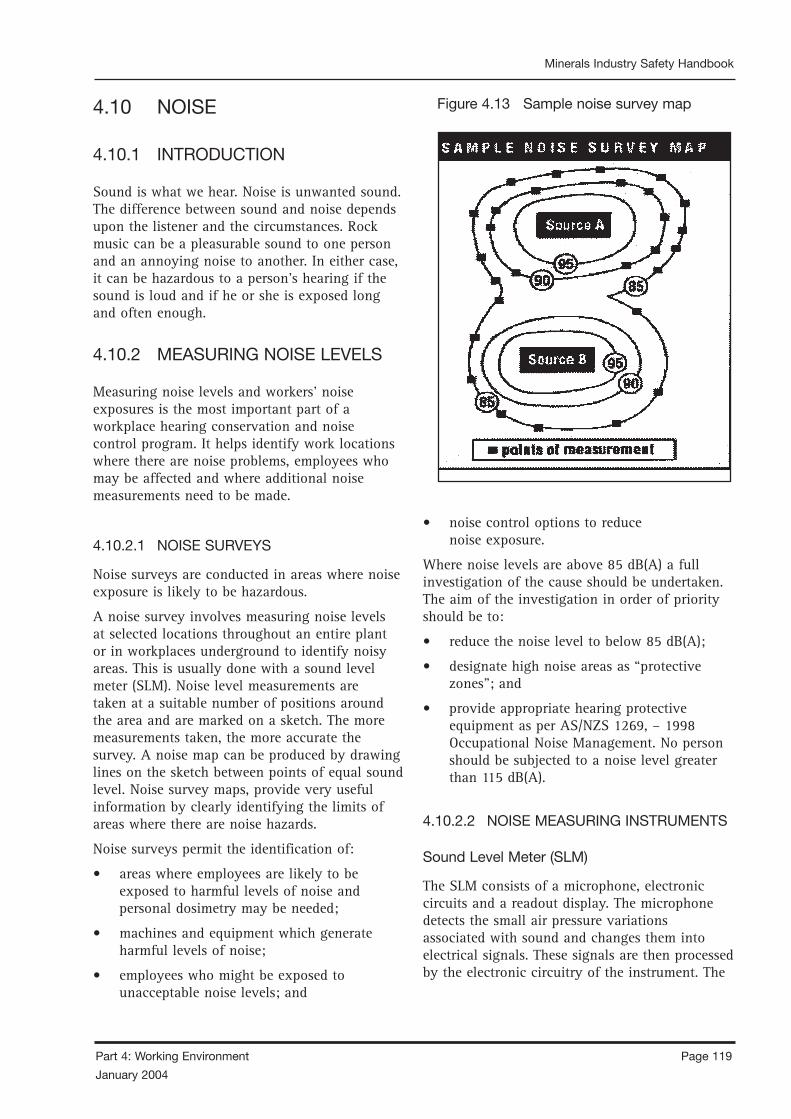
Page 118 Part 4: Working Environment
January 2004
Minerals Industry Safety Handbook
Part 4: Working Environment Page 119
January 2004
Minerals Industry Safety Handbook
4.10 NOISE
4.10.1 INTRODUCTION
Sound is what we hear. Noise is unwanted sound. The difference between sound and noise depends upon the listener and the circumstances. Rock music can be a pleasurable sound to one person and an annoying noise to another. In either case, it can be hazardous to a person’s hearing if the sound is loud and if he or she is exposed long and often enough.
4.10.2 MEASURING NOISE LEVELS
Measuring noise levels and workers’ noise exposures is the most important part of a workplace hearing conservation and noise control program. It helps identify work locations where there are noise problems, employees who may be affected and where additional noise measurements need to be made.
4.10.2.1 NOISE SURVEYS
Noise surveys are conducted in areas where noise exposure is likely to be hazardous.
A noise survey involves measuring noise levels at selected locations throughout an entire plant or in workplaces underground to identify noisy areas. This is usually done with a sound level meter (SLM). Noise level measurements are taken at a suitable number of positions around the area and are marked on a sketch. The more measurements taken, the more accurate the survey. A noise map can be produced by drawing lines on the sketch between points of equal sound level. Noise survey maps, provide very useful information by clearly identifying the limits of areas where there are noise hazards.
Noise surveys permit the identification of:
• areas where employees are likely to be exposed to harmful levels of noise and personal dosimetry may be needed;
• machines and equipment which generate harmful levels of noise;
• employees who might be exposed to unacceptable noise levels; and
• noise control options to reduce noise exposure.
Where noise levels are above 85 dB(A) a full investigation of the cause should be undertaken. The aim of the investigation in order of priority should be to:
• reduce the noise level to below 85 dB(A);
• designate high noise areas as “protective zones”; and
• provide appropriate hearing protective equipment as per AS/NZS 1269, – 1998 Occupational Noise Management. No person should be subjected to a noise level greater than 115 dB(A).
4.10.2.2 NOISE MEASURING INSTRUMENTS
Sound Level Meter (SLM)
The SLM consists of a microphone, electronic circuits and a readout display. The microphone detects the small air pressure variations associated with sound and changes them into electrical signals. These signals are then processed by the electronic circuitry of the instrument. The
Figure 4.13 Sample noise survey map
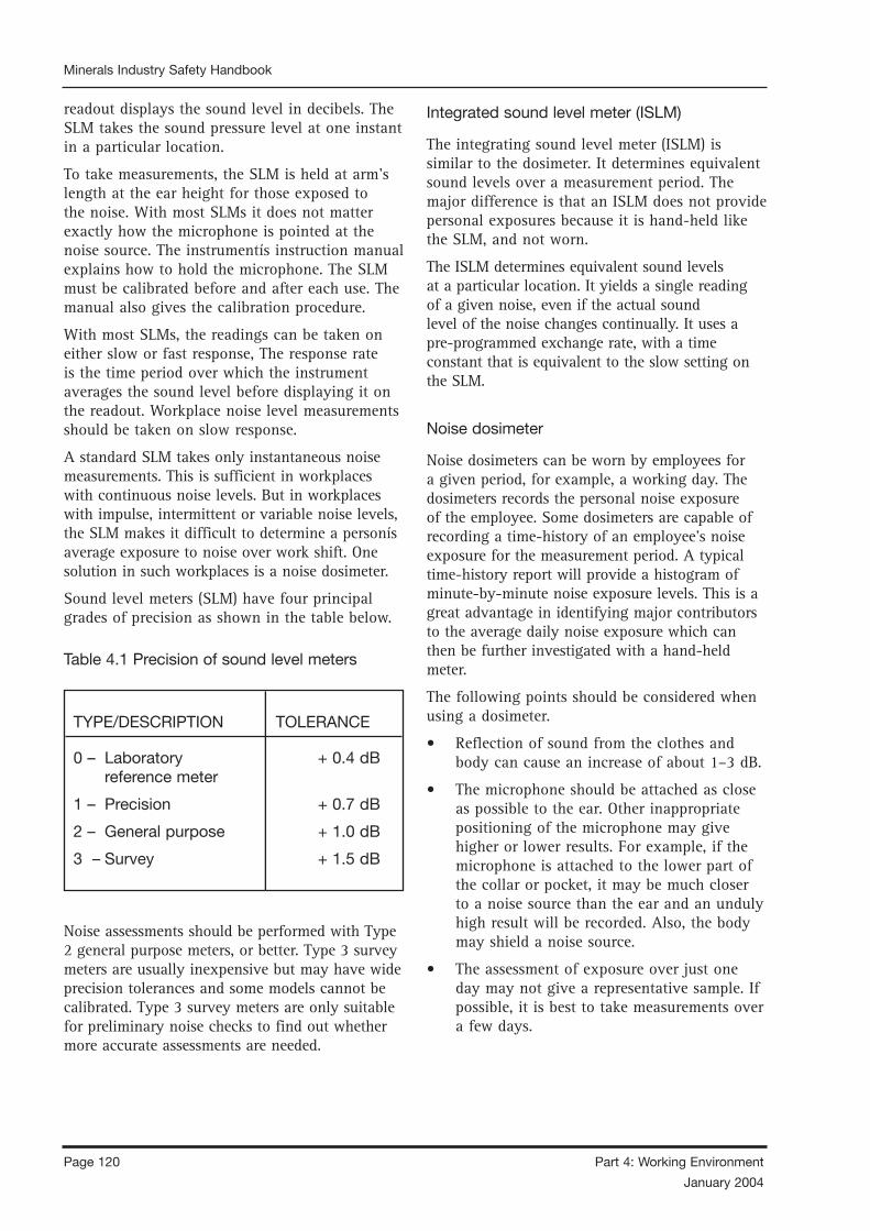
Page 120 Part 4: Working Environment
January 2004
Minerals Industry Safety Handbook
Part 4: Working Environment Page 121
January 2004
Minerals Industry Safety Handbook
readout displays the sound level in decibels. The SLM takes the sound pressure level at one instant in a particular location.
To take measurements, the SLM is held at arm’s length at the ear height for those exposed to the noise. With most SLMs it does not matter exactly how the microphone is pointed at the noise source. The instrumentís instruction manual explains how to hold the microphone. The SLM must be calibrated before and after each use. The manual also gives the calibration procedure.
With most SLMs, the readings can be taken on either slow or fast response, The response rate is the time period over which the instrument averages the sound level before displaying it on the readout. Workplace noise level measurements should be taken on slow response.
A standard SLM takes only instantaneous noise measurements. This is sufficient in workplaces with continuous noise levels. But in workplaces with impulse, intermittent or variable noise levels, the SLM makes it difficult to determine a personís average exposure to noise over work shift. One solution in such workplaces is a noise dosimeter.
Sound level meters (SLM) have four principal grades of precision as shown in the table below.
Table 4.1 Precision of sound level meters
TYPE/DESCRIPTION TOLERANCE
0 – Laboratory + 0.4 dB reference meter
1 – Precision + 0.7 dB
2 – General purpose + 1.0 dB
3 – Survey + 1.5 dB
Noise assessments should be performed with Type 2 general purpose meters, or better. Type 3 survey meters are usually inexpensive but may have wide precision tolerances and some models cannot be calibrated. Type 3 survey meters are only suitable for preliminary noise checks to find out whether more accurate assessments are needed.
Integrated sound level meter (ISLM)
The integrating sound level meter (ISLM) is similar to the dosimeter. It determines equivalent sound levels over a measurement period. The major difference is that an ISLM does not provide personal exposures because it is hand-held like the SLM, and not worn.
The ISLM determines equivalent sound levels at a particular location. It yields a single reading of a given noise, even if the actual sound level of the noise changes continually. It uses apre-programmed exchange rate, with a time constant that is equivalent to the slow setting on the SLM.
Noise dosimeter
Noise dosimeters can be worn by employees for a given period, for example, a working day. The dosimeters records the personal noise exposure of the employee. Some dosimeters are capable of recording a time-history of an employee’s noise exposure for the measurement period. A typical time-history report will provide a histogram of minute-by-minute noise exposure levels. This is a great advantage in identifying major contributors to the average daily noise exposure which can then be further investigated with a hand-held meter.
The following points should be considered when using a dosimeter.
• Reflection of sound from the clothes and body can cause an increase of about 1–3 dB.
• The microphone should be attached as close as possible to the ear. Other inappropriate positioning of the microphone may give higher or lower results. For example, if the microphone is attached to the lower part of the collar or pocket, it may be much closer to a noise source than the ear and an unduly high result will be recorded. Also, the body may shield a noise source.
• The assessment of exposure over just one day may not give a representative sample. If possible, it is best to take measurements over a few days.

Page 120 Part 4: Working Environment
January 2004
Minerals Industry Safety Handbook
Part 4: Working Environment Page 121
January 2004
Minerals Industry Safety Handbook
• It is advisable to check the dosimeter results with a hand-held sound level meter.
• Some dosimeters do not measure impulse sound adequately.
• Dosimeters should comply with Australian Standard AS 2399 (except that the crest factor should exceed 10 if used for impulse sound).
• All SLMs and ISLMs should comply with the specifications laid down AS 1259, – 1990 Acoustics Sound Level Makers.
• A full calibration of measuring systems should be performed at regular intervals not exceeding two years by a laboratory approved for the purpose.
• Meters should be checked with an acoustic calibrator immediately before and after the measurements.
A-weighted decibels
The sensitivity of the human ear to sound depends on the frequency or pitch of the sound. People hear some frequencies better than others. If a person hear two sounds of the same sound pressure but different frequencies, one sound may appear louder than the other. This occurs because
people hear high frequency noise much better than low frequency noise.
Noise measurement readings can be adjusted to correspond to this peculiarity of human bearing. An A-weighting filter which is built into the instrument de-emphasises low frequencies or pitches. Decibels measured using this filter are A-weighted and are called dB(A). Legislation on workplace noise normally gives exposure limits in dB(A).
Noise levels in decibels for some commonly heard sounds are given in Table 4.2.
A-weighting serves two important purposes:• gives a single number measure of noise level
by integrating sound levels at all frequencies; and
• gives a scale for noise level as experienced or perceived by the human ear.
The decibel [dB, and also dB(A)] is dimensionless and is derived for intensity readings using a logarithmic scale. For mathematical calculations using dB units, we must use logarithmic mathematics where:
Intensity in decibels (dB) = 10 log 10 (intensity 1/intensity 2)
3 dB increase Sound energy doubled
3 dB decrease Sound energy halved
10 dB increase Sound energy increased by factor of 10
10 dB decrease Sound energy decreased by factor of 10
20 dB increase Sound energy increased by factor of 100
20 dB decrease Sound energy decreased by factor of 100
NOISE SOUND LEVELS (DBA)
May break a plate glass window 160
Threshold of pain 120
Pneumatic drill 100-120
Shovel (diesel) 107
Timber saw 100
Screens 95-100
Compressor 90-100
Cursher 90-100
bulldozer 85-106
FEL/dump truck 80- 95
City traffic 65- 75
Quiet office 50
Threshold of hearing 0
Table 4. 2 Typical noise levels Table 4.3 Decibel (dB) basics
CHANGE IN DB CHANGE IN SOUND ENERGY
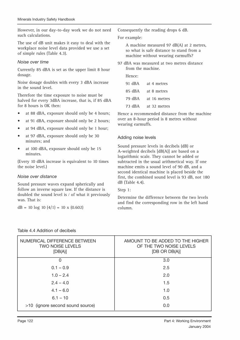
Page 122 Part 4: Working Environment
January 2004
Minerals Industry Safety Handbook
Part 4: Working Environment Page 123
January 2004
Minerals Industry Safety Handbook
However, in our day-to-day work we do not need such calculations.
The use of dB unit makes it easy to deal with the workplace noise level data provided we use a set of simple rules (Table 4.3).
Noise over time
Currently 85 dBA is set as the upper limit 8 hour dosage.
Noise dosage doubles with every 3 dBA increase in the sound level.
Therefore the time exposure to noise must be halved for every 3dBA increase, that is, if 85 dBA for 8 hours is OK then:
• at 88 dBA, exposure should only be 4 hours;
• at 91 dBA, exposure should only be 2 hours;
• at 94 dBA, exposure should only be 1 hour;
• at 97 dBA, exposure should only be 30 minutes; and
• at 100 dBA, exposure should only be 15 minutes.
(Every 10 dBA increase is equivalent to 10 times the noise level.)
Noise over distance
Sound pressure waves expand spherically and follow an inverse square law. If the distance is doubled the sound level is ⁄ of what it previously was. That is:
dB = 10 log 10 (4/1) = 10 x (0.602)
Consequently the reading drops 6 dB.
For example:
A machine measured 97 dB(A) at 2 metres, so what is safe distance to stand from a machine without wearing earmuffs?
97 dBA was measured at two metres distance from the machine.
Hence:
91 dBA at 4 metres
85 dBA at 8 metres
79 dBA at 16 metres
73 dBA at 32 metres
Hence a recommended distance from the machine over an 8-hour period is 8 metres without wearing earmuffs.
Adding noise levels
Sound pressure levels in decibels (dB) or A-weighted decibels [dB(A)] are based on a logarithmic scale. They cannot be added or subtracted in the usual arithmetical way. If one machine emits a sound level of 90 dB, and a second identical machine is placed beside the first, the combined sound level is 93 dB, not 180 dB (Table 4.4).
Step 1:
Determine the difference between the two levels and find the corresponding row in the left hand column.
Table 4.4 Addition of decibels
NUMERICAL DIFFERENCE BETWEEN AMOUNT TO BE ADDED TO THE HIGHER TWO NOISE LEVELS OF THE TWO NOISE LEVELS [DB(A)] [DB OR DB(A)]
0 3.0
0.1 – 0.9 2.5
1.0 – 2.4 2.0
2.4 – 4.0 1.5
4.1 – 6.0 1.0
6.1 – 10 0.5
>10 (ignore second sound source) 0.0

Page 122 Part 4: Working Environment
January 2004
Minerals Industry Safety Handbook
Part 4: Working Environment Page 123
January 2004
Minerals Industry Safety Handbook
Step 2:
Find the number [dB or dB(A)] corresponding to this difference in the right hand column of the table.
Step 3:
Add this number to the higher of the two decibel levels.
4.10.3 CONTROLLING NOISE EXPOSURE
4.10.3.1 GENERAL
Noise-related illnesses are the most common health risks for miners.
General managers should determine conditions and sites in which hearing devices must be worn in mines.
A hearing protection device should conform with AS 1270 Acoustics – Hearing Protectors.
Mine owners should:
• supply staff with hearing protection devices; and
• ensure employees, contractors and visitors maintain hearing protection devices.
4.10.3.2 ENGINEERING NOISE CONTROL
The best form of protection is the reduction of noise to an acceptable level at the working place.
Noise control is an engineering problem and it requires the services of experts to reduce the noise output from a machine by redesigning it or installing acoustic covers and barriers.
4.10.3.3 USE OF EAR PROTECTION
Personal hearing protection should be used only where technical or economic considerations prevent the reduction of noise to below the levels prescribed. The function of the hearing protection device is to reduce the amount of noise reaching the inner ear of the wearer by covering the ear, covering the entrance to the ear, or blocking the ear canal with an ear plug.
The devices used by individuals must suit them personally and be appropriate to the working environment. There are many forms of ear protection available, but most fall into the following categories.
4.10.3.4 REDUCTION OF EXPOSURE TIME
In some cases it is possible to have employees in sound-proof enclosures to perform certain tasks in order to shield them from a particular noise by means of barriers or baffles. However, in many situations this cannot be done; where the noise approached the set limit, an arrangement of tasks should be made for individuals so that they are not exposed to the noise for too long a period at any one time.
Part of a well-designed hearing conservation program should involve education about the adverse effects of noise exposure away from the working place. Exposure to noises such as using a lawnmower, power tools, or listening to loud music can contribute significantly to a person’s overall daily noise dose.
4.10.3.5 NOISE CONTROL STRATEGY
Mine operators should ensure that a strategy for noise control includes:
• reducing noise at work sites to the lowest practical level. Determine exposure to noise in accordance with AS/NZS 1269, Occupational Noise Management;
• monitoring employees’ exposure to noise at work sites. Use survey findings to determine necessary precautions and the need for a noise control program;
• keeping written records of noise monitoring surveys for at least three years after an employee ceases to work at the mine; and
• making results (records and surveys) available to an Inspector of Mines and eventually forwarding to the appropriate authority for archiving.
To establish a comprehensive noise control program, general managers should:
Page 124 Part 4: Working Environment
January 2004
Minerals Industry Safety Handbook
Part 4: Working Environment Page 125
January 2004
Minerals Industry Safety Handbook
• Ensure noise levels are regularly measured and recorded. Noise levels should be recorded on an “A Scale” in decibels (dB), and dB levels should be known at all work sites signposted “noisy”. If noise levels vary, averages should be recorded (Leq) so noise dose can be determined.
• Ensure appropriate engineering controls to reduce noise levels are used where practical.
Examine all forms of noise and reduce “easy-to-control” noise including rattling guards and high pressure air leaks.
Investigate effectiveness of other methods of noise control and consult noise specialists.
• Identify and signpost high noise areas and designate them as “protective” zones.
Areas where noise exceeds statutory action levels should be clearly designated. Hearing protectors (muffs or plugs) should be worn at all times in any “protective” zone or where noise could damage hearing. Before selecting hearing protectors, refer to AS 1269 Acoustics – Hearing Conservation.
• Provide adequate training.
All personnel should understand the importance of hearing protectors and should be trained to use and maintain protectors. noise management and control.
Management and supervisors must take all steps to reduce noise-induced hearing loss.
• Prepare necessary noise control and reduction procedures.
Include noise procedures in company health and safety policy statements, work system documents, conditions of employment, purchase specifications and orders for new machinery.
Noise problems should be removed at the start of projects and on installation of new equipment.
Review methods of noise reduction before during, and after installation of new equipment.
Accepted average noise levels for a work site may change and may not be practical after new machinery and equipment is installed and in use.
• Investigate benefits of audiometry.
Audiometric hearing tests gauge an individual’s hearing level and can aid in early detection of hearing disorders.
Only trained staff in fully equipped laboratories should conduct audiometric hearing tests.
• Monitor and periodically review noise levels to ensure the best noise reduction methods are used.
REFERENCE DOCUMENTS
AS/NZS 1269, – 1998 Occupational Noise Management.
AS 1270 – 1988 Acoustics – Hearing Protectors. “Workplace Noise” – Basic Information, Canadian Centre for Occupational Health and Safety.
“Code of Practice for Noise Management and Protection of Hearing at Work” – NSW WorkCover on Disk, Codes of Practice.
“Handbook on Quarrying” – Department of Mines and Energy, South Australia.
“Measurement of Workplace Noise”, Canadian Centre for Occupational Health and Safety.
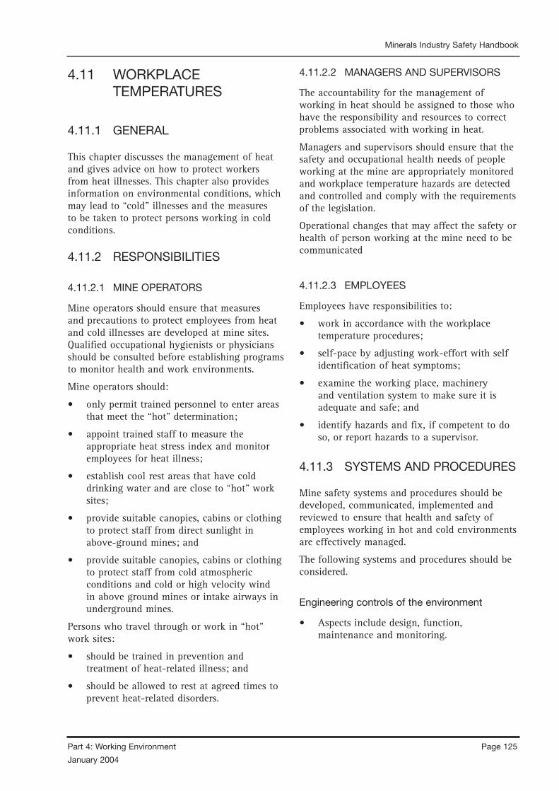
Page 124 Part 4: Working Environment
January 2004
Minerals Industry Safety Handbook
Part 4: Working Environment Page 125
January 2004
Minerals Industry Safety Handbook
4.11 WORKPLACE TEMPERATURES
4.11.1 GENERAL
This chapter discusses the management of heat and gives advice on how to protect workers from heat illnesses. This chapter also provides information on environmental conditions, which may lead to “cold” illnesses and the measures to be taken to protect persons working in cold conditions.
4.11.2 RESPONSIBILITIES
4.11.2.1 MINE OPERATORS
Mine operators should ensure that measures and precautions to protect employees from heat and cold illnesses are developed at mine sites. Qualified occupational hygienists or physicians should be consulted before establishing programs to monitor health and work environments.
Mine operators should:
• only permit trained personnel to enter areas that meet the “hot” determination;
• appoint trained staff to measure the appropriate heat stress index and monitor employees for heat illness;
• establish cool rest areas that have cold drinking water and are close to “hot” work sites;
• provide suitable canopies, cabins or clothing to protect staff from direct sunlight in above-ground mines; and
• provide suitable canopies, cabins or clothing to protect staff from cold atmospheric conditions and cold or high velocity wind in above ground mines or intake airways in underground mines.
Persons who travel through or work in “hot” work sites:
• should be trained in prevention and treatment of heat-related illness; and
• should be allowed to rest at agreed times to prevent heat-related disorders.
4.11.2.2 MANAGERS AND SUPERVISORS
The accountability for the management of working in heat should be assigned to those who have the responsibility and resources to correct problems associated with working in heat.
Managers and supervisors should ensure that the safety and occupational health needs of people working at the mine are appropriately monitored and workplace temperature hazards are detected and controlled and comply with the requirements of the legislation.
Operational changes that may affect the safety or health of person working at the mine need to be communicated
4.11.2.3 EMPLOYEES
Employees have responsibilities to:
• work in accordance with the workplace temperature procedures;
• self-pace by adjusting work-effort with self identification of heat symptoms;
• examine the working place, machinery and ventilation system to make sure it is adequate and safe; and
• identify hazards and fix, if competent to do so, or report hazards to a supervisor.
4.11.3 SYSTEMS AND PROCEDURES
Mine safety systems and procedures should be developed, communicated, implemented and reviewed to ensure that health and safety of employees working in hot and cold environments are effectively managed.
The following systems and procedures should be considered.
Engineering controls of the environment
• Aspects include design, function, maintenance and monitoring.

Page 126 Part 4: Working Environment
January 2004
Minerals Industry Safety Handbook
Part 4: Working Environment Page 127
January 2004
Minerals Industry Safety Handbook
Job design
This should take into consideration:
• work-load;
• acclimatisation of employees and contractors;
• shift arrangements and rest periods;
• job rotation;
• work rates; and
• flexibility to reduce work rate and physical demands to accommodate changes in temperature, air flow and humidity.
Work arrangements
This should include:
• job pacing where employees self-pace the rate of work to match individual tolerances;
• supervision to monitor and action changes in the workplace where the adverse effects of heat or cold are identified; and
• environmental monitoring.
Emergency and rescue
• Emergency, rescue and first aid procedures have been tested.
Job safety analysis
• Work tasks that are identified as having a risk should be analysed step-by-step to pinpoint the hazards and to identify controls for implementation before the work is commenced. This information can then be written into the work procedure.
4.11.3.1 WORK PROCEDURES AND PERMIT
TO WORK SYSTEMS
The inclusion of special arrangements should be incorporated into general procedures where exposures have been identified.
It may include triggers or actions where decisions are made to cease the work and/or withdraw or replace employees from a work area.
These triggers should be:
• measurable or observable (temperature, air flow;
• in line with statutory and company requirements;
• identified by risk assessment, unless statutory;
• set recognising the normal or background conditions;
• relevant to the risk being considered;
• reflect the level of risk and degree of response required;
• set after the results of any similar testing;
• set to a level that recognises the time taken to initiate effective response (ie developing a staged response to triggers which will depend on the severity of the risk); and
• developed by agreement with all stakeholders.
Depending on the degree of urgency of the trigger, actions could be (but not be limited to);
• the collection of additional data to determine a course of action;
• withdrawal of employees from an area;
• substitution of unacclimatised employees for acclimatised employees; or
• initiation of emergency response plans.
Note: A sample “standard” for working in heat is provided in Appendix 4.1 at the end of Section 4.11.
4.11.3.2 TRAINING AND EDUCATION
Training on the effects of heat should be conducted periodically for employees and others who work in heat environments. Work in heat or cold procedures, and where applicable testing arrangements, should be included in induction training for employees and contractors.
Training and education topics should be appropriate to the work environment, and could include:

Page 126 Part 4: Working Environment
January 2004
Minerals Industry Safety Handbook
Part 4: Working Environment Page 127
January 2004
Minerals Industry Safety Handbook
• systems and procedures on site;
• acclimatisation;
• workplace monitoring;
• fitness for work;
• emergency and first aid; and
• PPE, hazards of exposure.
4.11.3.3 DOCUMENTATION AND
DOCUMENT CONTROL
There should be mine safety systems in place to control the documentation at the workplace. The following types of documentation to consider may include:
• work environment monitoring data and reports;
• procedures;
• policies;
• mine safety systems;
• training records;
• health records;
• permits to work; and
• induction records.
These records should be stored and maintained for ease of reference. Health and medical records should be stored in a confidential file with restricted access.
A sample “permit” for working in heat is provided in Appendix 4.2 at the end of Section 4.11.s
4.11.3.4 MEASUREMENT AND MONITORING
Incident reporting systems should include any incidents related to heat effects. These should be recorded and analysed to detect trends, which may require corrective actions.
The systems and procedures for managing exposures should be periodically reviewed through auditing processes, which, may be as part of a safety management system, audit, or as a discrete audited unit. Internal and/or external audits should be considered.
The outcomes of any measures or monitoring should be fed back into the management review process.
Management review
Management should review the systems and procedures for managing hot and cold environments to ensure that the systems are effective and updated to keep pace with technology and research, and that they remain appropriate to the work site.
Figure 4.14 Sling psychrometer

Page 128 Part 4: Working Environment
January 2004
Minerals Industry Safety Handbook
Part 4: Working Environment Page 129
January 2004
Minerals Industry Safety Handbook
4.11.4 HEAT
When the body is unable to cool itself through sweating, serious heat illnesses may occur. The most severe heat-induced illnesses are heat exhaustion and heat stroke. If actions are not taken to treat heat exhaustion, the illness could progress to heat stroke and possible death.
4.11.4.1 IDENTIFICATION OF HEAT HAZARDS
The identification of hazards is the first step in the process of risk management. The identification of hazards should include the following:
• consultation, with people working at the mine;
• analysis of incidents;
• analysis of health monitoring;
• analysis of workplace monitoring; and
• identification of heat sources where new equipment is being purchased, or where changes to processes or the workplace environment are planned.
As a guide the following may assist in the process of identifying areas where heat sources could occur:
• high level of radiant heat emitted from machinery, rock or naturally occurring high ambient temperatures;
• areas where ventilation is poor or where airflow is minimal; and/or
• areas where physical exertion is greatest; and/or
• areas with no protection from solar heat; and/or
• unscheduled physical activity where the above conditions may be present.
4.11.4.2 ASSESSMENT OF HEAT HAZARDS
Assessment of heat hazards should, as a minimum, take into account, the:
• heat factors associated with work environment;
• tasks to be performed and duration of the
work;
• fitness, hydration levels and acclimatisation of the people performing the work;
• personal protective equipment used and its effect on the body’s ability to cool through perspiration; and
• availability of fluid replacements.
Workers are at increased risk when:
• they are dehydrated;
• they take certain medication (check with your doctor, nurse or pharmacy and ask if any medicines that a person is taking are likely to give an adverse effect when working in hot environments);
• they have had a heat-induced illness in the past; and
• they wear personal protective equipment such as respirators or suits.
4.11.4.3 DETERMINING HEAT CONDITIONS
The main heat indices are as follows:
Wet bulb globe temperature
The “wet bulb globe temperature” (WBGT) is a weighted average of temperatures indicated by wet bulb (WB), dry bulb (DB) and globe (GT) thermometers. The method of measurement is as follows.
• Suspend the three types of thermometers from stands in conditions as close as possible to those of the work site. Air should flow freely around the three thermometers. Shield dry bulb thermometers from sun and radiant heat. Do not shield wet or globe bulb thermometers. Keep wicks of wet bulb thermometers clean and wet with distilled water.
• Read dry and globe bulb temperatures using conventional methods. Wet bulb thermometers do not need artificial ventilation and should be read after they are deliberately exposed to radiation. Temperatures measured in this way are known as “natural wet bulb” temperatures.
• Glass thermometers with mercury are recommended for all three measurements. However, other types of temperature sensors
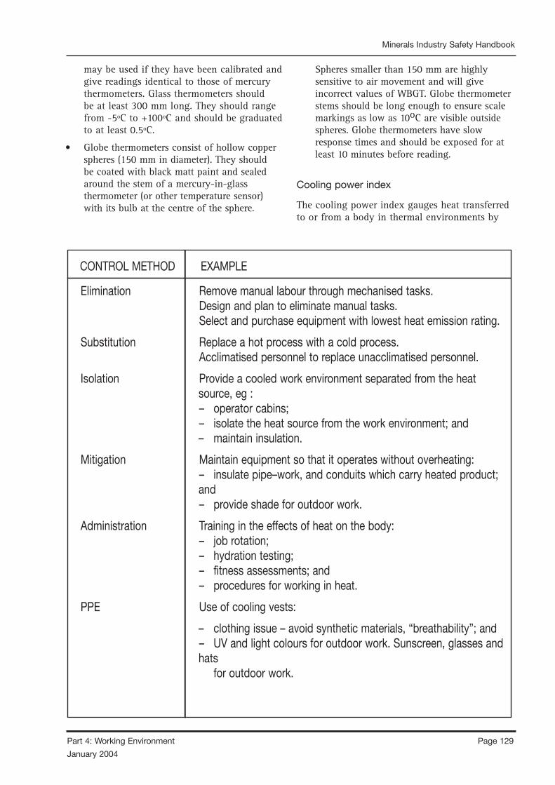
Page 128 Part 4: Working Environment
January 2004
Minerals Industry Safety Handbook
Part 4: Working Environment Page 129
January 2004
Minerals Industry Safety Handbook
may be used if they have been calibrated and give readings identical to those of mercury thermometers. Glass thermometers should be at least 300 mm long. They should range from -5ºC to +100ºC and should be graduated to at least 0.5ºC.
• Globe thermometers consist of hollow copper spheres (150 mm in diameter). They should be coated with black matt paint and sealed around the stem of a mercury-in-glass thermometer (or other temperature sensor) with its bulb at the centre of the sphere.
Spheres smaller than 150 mm are highly sensitive to air movement and will give incorrect values of WBGT. Globe thermometer stems should be long enough to ensure scale markings as low as 10oC are visible outside spheres. Globe thermometers have slow response times and should be exposed for at least 10 minutes before reading.
Cooling power index
The cooling power index gauges heat transferred to or from a body in thermal environments by
CONTROL METHOD EXAMPLE
Elimination Remove manual labour through mechanised tasks.Design and plan to eliminate manual tasks.Select and purchase equipment with lowest heat emission rating.
Substitution Replace a hot process with a cold process.Acclimatised personnel to replace unacclimatised personnel.
Isolation Provide a cooled work environment separated from the heat source, eg :– operator cabins;– isolate the heat source from the work environment; and– maintain insulation.
Mitigation Maintain equipment so that it operates without overheating:– insulate pipe–work, and conduits which carry heated product; and– provide shade for outdoor work.
Administration Training in the effects of heat on the body:– job rotation;– hydration testing;– fitness assessments; and– procedures for working in heat.
PPE Use of cooling vests:
– clothing issue – avoid synthetic materials, “breathability”; and– UV and light colours for outdoor work. Sunscreen, glasses and hats for outdoor work.

Page 130 Part 4: Working Environment
January 2004
Minerals Industry Safety Handbook
Part 4: Working Environment Page 131
January 2004
Minerals Industry Safety Handbook
STEPS
Ventilation Standards
1. Ensure vent duct is not more than 20 m from
the actual work place
2. Check vent line for tears and repair if necessary
3. Check vent doors and other local controls (e.g.
fans) are correctly set
4. Install a pump if casual water is present
5. Ensure adequate drinking water is on the job – 1
to 2 litres per hour per person
6. If conditions are oppressive, request supervisor
to check the MHB
Measurement and Recording
1. Measure WB, DB and wind speed as close as
practicable to working position of employee�s
upper body using whirling hygrometer and vane
anemometer
2. Determine WIH zone using charts
3. Record zone on shift report for each location
tested
Metabolic Heat Balance (MHB)
1. Unrestricted zone MHB > 220
a. No restrictions apply
2. Acclimatisation zone 140< MHB < 220
a. Unacclimatised workers must not work alone
3. Buffer zone 115< MHB < 140
a. Unacclimatised workers must not work at all
b. No lone or isolated workers
c. If airflow is less than 0.5 m/s, it must be
increased to at least 0.5 m/s
d. Ventilation to be fixed if defective
e. Employee to be redeployed if practical
f. If work continues, supervisor must complete
Corrective Action Request
g. Employee must have Dehydration test
4. Withdrawal zone MHB < 115 or WB > 32
or DB > 44
a. Work can only occur in safety emergency or
to fix the ventilation
b. Permit to Work in Heat must be authorised in
advance by the Manager
APPENDIX 4.1 SAMPLE MINE WORKING IN HEAT STANDARD
SPECIAL POINTS
1. Air movers are not to be instead of sufficient
primary ventilation
2. Primary ventilation must be at least 4 m3/s per
100 kW of rated diesel engine p
3. ower in the air intake to the job
4. Supervisor must make every attempt to get to
the job site within 2 hours of request.
5. If supervisor does not arrive within 2 hours,
relocate to cooler area
1. Show zone to employee
2. Avoid placing heat sources (hand or cap lamp)
near thermometers
3. Between October and March inclusive, MHB
must be measured in every workplace at least
once per shift for any employee working in
manual labour
1. Unacclimatised person is one who has been off-
work for any reason for more than 14 days
2. Unacclimatised person must have dehydration
test at end of shift for first week back at work
3. All cases of heat illness must be reported and
treated
4. No person suffering heat illness is to be left alone
or allowed to travel by himself
5. Supervisor must measure and report MHB at all
locations where heat illness symptoms are first
reported, or where an accident/incident occurs
6. Completed Corrective Action Requests and
Permits to Work in Heat must be sent to
Manager and Ventilation Officer within 48 hours
of incident
Compliance with this standard is mandatory

Page 130 Part 4: Working Environment
January 2004
Minerals Industry Safety Handbook
Part 4: Working Environment Page 131
January 2004
Minerals Industry Safety Handbook
Employee consents to conducting the work on the basis that the following has been discussed
– the nature of the job,
– the need to maintain fluid levels by drinking every 15 minutes
– the maximum work period is 20 minutes, followed by 40 minutes of rest
If any circle in the table is ticked, that person must not work under this permit
3. Fill in the following table
2. Fill in the following table, ticking any circle that applies, employees sign
APPENDIX 4.2 PERMIT TO WORK IN HHEAT
4. Supervisor signs form.
5. Return form to Manager within 48 hours.
1. Circle at least one item from each box
Must be completed BEFORE working in conditions where Reason for permit to be
issued:
• MHB is less than 115, OR fixing ventilation
• WB is greater than 320, OR safety
• DB is greater than 440
Brief description of activity Date
Supervisor (print) Location
Employee Employer Required to Unacclimatised Woman of Consent ofName work alone child-bearing employee capacity (refer below)
O O O O O O O O O O O O
Name of responsible person on job at all times (print)
Type of emergency communication Check emergency communication OK (time)
Start time Expected duration Finish time
Managers approval granted (time) Adequate water on job (min 1 litre/person/hour)
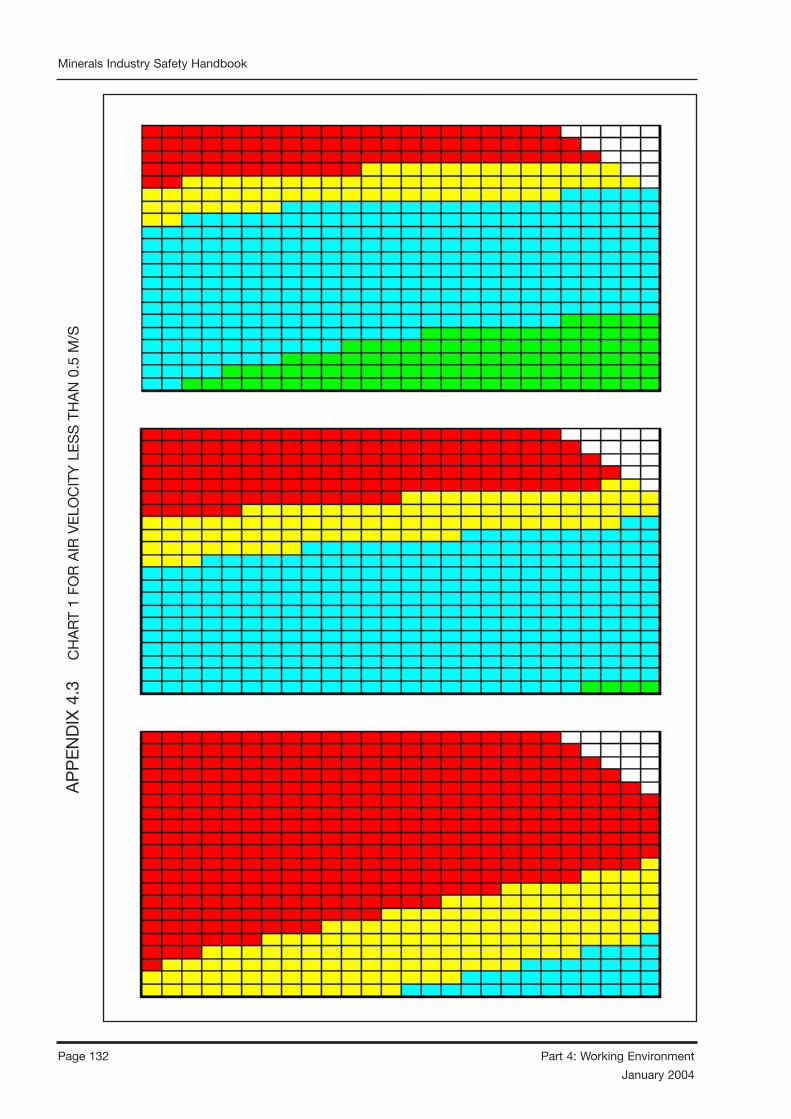
Page 132 Part 4: Working Environment
January 2004
Minerals Industry Safety Handbook
Part 4: Working Environment Page 133
January 2004
Minerals Industry Safety HandbookA
PP
EN
DIX
4.3
CH
AR
T 1
FOR
AIR
VE
LOC
ITY
LE
SS
TH
AN
0.5
M/S

Page 132 Part 4: Working Environment
January 2004
Minerals Industry Safety Handbook
Part 4: Working Environment Page 133
January 2004
Minerals Industry Safety Handbook
AP
PE
ND
IX 4
.3
C
HA
RT
2 FO
R A
IR V
ELO
CIT
Y G
RE
ATE
R T
HA
N 0
.5 M
/S
REFE
R to
Pro
cedu
re “
Wor
king
In
Hea
t”
WIT
HD
RAW
AL
regi
on (
red)
MH
B le
ss t
han
115
or W
B>32
or
DB>
44)
No
wor
k al
low
ed e
xcep
t in
saf
ety
emer
genc
y or
to
fix
vent
ilatio
n.
Perm
it to
Wor
k in
Hea
t re
quir
ed.
Com
puls
ory
dehy
drat
ion
test
at
end
of s
hift
BUFF
ER r
egio
n (y
ello
w)
MH
B be
twee
n 11
5 an
d 14
0)Fi
x ve
nt o
r re
depl
oy p
erso
n if
pos
sibl
e.N
o pe
rson
to
wor
k al
one
No
unac
clim
atis
ed p
erso
n to
wor
k.If
wor
k co
ntin
ues,
Cor
rect
ive
Act
ion
Requ
est
mus
t be
com
plet
ed a
nd s
igne
d by
man
ager
with
in 4
8 hr
s.Co
mpu
lsor
y de
hydr
atio
n te
st a
t en
d of
shi
ft
ACC
LIM
ATI
SED
reg
ion
(blu
e)M
HB
betw
een
140
and
220)
Una
cclim
atis
ed p
erso
ns m
ay w
ork
but
not
alon
e.
UN
REST
RICT
ED r
egio
n (g
reen
)M
HB
mor
e th
an 2
20)
No
rest
rict
ions
app
ly.
NO
TE:
If
MH
B <
140,
win
d sp
eed
mus
t be
inc
reas
ed t
o at
leas
t 0.
5 m
/sec
by
impr
ovin
g ve
nt o
r in
stal
ling
airm
over
.
How
to
mea
sure
MH
B be
fore
Hea
t St
ress
Met
ers
Arr
ive
1.
Ensu
re t
he g
lass
is
full
of w
ater
and
the
wic
k is
wet
and
cle
an.
2.
Swin
g th
e gl
ass
for
30 s
econ
ds a
nd r
ead
the
wet
bul
b im
med
iate
ly.
3.
Re-s
win
g th
e th
e gl
ass
for
a fu
rthe
r 30
sec
onds
and
rea
d th
e w
et
bu
lb i
mm
edia
tely
. Use
the
hig
her
of t
he t
wo
read
ings
.4.
Re
ad t
he d
ry b
ulb.
5.
Kee
p yo
ur c
ap l
amp
away
fro
m t
he t
herm
omet
ers.
6.
Mea
sure
the
win
d sp
eed
in m
eter
s pe
r se
cond
usi
ng t
he a
nem
omet
er.
7.
Sele
ct t
he c
orre
ct c
hart
acc
ordi
ng t
o w
ind
spee
d.8.
Fi
nd t
he c
ell
in t
he c
hart
tha
t co
rres
pond
s to
the
wet
and
dry
bul
b9.
Ta
ke t
he a
ppro
pria
te a
ctio
n (s
ee a
bove
plu
s th
e Pr
oced
ure
de
pend
ing
on w
hat
regi
on o
f th
e ch
art
the
wor
kpla
ce f
alls
int
o.
NO
TE:
tem
pera
ture
s an
d ai
rflo
w a
re t
o be
mea
sure
d in
the
wor
king
are
a
at t
he l
ocat
ion
of t
he e
mpl
oyee
’s u
pper
bod
y.
Page 134 Part 4: Working Environment
January 2004
Minerals Industry Safety Handbook
Part 4: Working Environment Page 135
January 2004
Minerals Industry Safety Handbook
radiation, convection and evaporation, and is measured in Watts per square metre W/m2). The method of measurement is as follows.
• To obtain the cooling power index, measure wet and dry bulb air temperatures with a whirling hygrometer in an environment representative of the work site and refer these to the appropriate charts for different air velocities.
• Mercury in glass thermometers are recommended. However, other temperature sensors may be used if they are calibrated and give identical readings to mercury thermometers. Mercury in glass thermometers should range from -5°C to +50°C and should be graduated at 0.5°C intervals. Keep wet bulb thermometer wicks clean and damp with distilled water.
• Read wet and dry bulb temperatures in hot work sites during every working shift. Read air velocity at least once a month or when there are changes to air flow rates. If air velocity at a work site is unknown, it should be taken to be less than 0.2 m/s.
To determine indices for “hot” environments:
• measure ambient air temperatures in degrees Celsius from wet bulbs, dry bulbs and globes;
• use thermometers that comply with the British Standard 2842; and
• use calibrated vane anemometers to measure air velocities in metres per second.
4.11.4.4 CONTROL OF RISK
The hierarchy of controls approach can be utilised when addressing heat hazards. This involves considering the most effective way of controlling a risk.
• Elimination – Is it possible to remove the problem by engineering methods, or design changes, or by getting rid of the problem all together.
• Substitution – Is it possible to replace the problem with something less hazardous?
• Isolation – Can a barrier be put between the person and the hazard? For example – by distance, a control room.
• Mitigation – Can the hazard be lessened, by reducing the exposure of people, or by reducing the form of the hazard?
• Administration – For example, job rotation, training, work procedures, permit to work systems.
• Personal protective equipment – PPE is considered the last resort, as it is the least effective method of managing risk.
Some examples of controlling the risk of heat stress using this method are listed in the table below:
4.11.4.5 CONTROLLING EXPOSURE
TO PERSONS
Training and education topics should be appropriate to the work environment, and could include:
• understanding the ventilation system in workplaces in underground mines;
• measure atmospheric temperatures in places where people are working;
• learning the signs and symptoms of heat-induced illnesses and what to do to help an affected person;
• in above ground mines perform the heaviest work in the coolest part of the day;
• slowly build up tolerance to the heat and the work activity (usually takes up to 2 weeks);
• use the buddy system (work in pairs);
• drink plenty of cool water;
• wear light, loose-fitting, breathable clothing;
• take frequent short breaks in cool areas;
• avoid eating large meals before working in hot environments; and
• avoid caffeine and alcoholic beverages (these beverages make the body lose water and increase the risk for heat illnesses).
Note: Paced work is work where the worker is unable to regulate his own work rate. In practice, this means situations where the worker is unable to reduce his work rate

Page 134 Part 4: Working Environment
January 2004
Minerals Industry Safety Handbook
Part 4: Working Environment Page 135
January 2004
Minerals Industry Safety Handbook
or unable to take rest pauses as he deems necessary for his own health and safety.
Self-paced work is work where the worker is able to reduce his work rate and take rest pauses as he deems necessary for his own health and safety.
4.11.4.6 TRAINING OF EMPLOYEES AND VISITORS
Identify the education and training needs to address each specific hazard. All persons whose work may impact upon that hazard should receive appropriate training.
Establish and maintain procedures to make its employees at each relevant function and level aware of:
• the importance of conformance with procedures and with the requirements of managing heat;
• the significant safety impacts, actual or potential of their work activities and the safety benefits of improved personal performance;
• their roles and responsibilities in achieving conformance with procedures and with the requirements of management systems, including emergency preparedness and response requirements; and
• the potential hazards and consequences of departure from established procedures.
Provide for employees to complete the general training modules as part of the induction training for the mine and receive refresher training at schedule / regular intervals.
Ensure visitors and non-permanent employees receive suitable induction with regards to heat they may encounter.
Ensure mine rescue and other emergency workers receive suitable training with regard to management of heat stress. In many cases, this will require a separate hazard management plan for heat stress for these workers. This plan would need to take into account the emergency nature of their work, and the fact that they are usually working under self-contained breathing apparatus.
For persons with defined responsibilities and authority with respect to managing heat, the
required competency standards for each position should be determined. Training modules, aimed at developing competencies of selected personnel should be incorporated as an internal standard for the mine, eg. recognition of heat illness symptoms. Employees should have to demonstrate that they have attained the required competency.
The education and training program should include components on hydration, pacing and the working in heat protocols. The working in heat protocols should include but not be limited to:
• the correct actions before, during and after work shifts;
• first aid, both for themselves and for any affected workmates;
• basic understanding of heat illness, particularly the symptoms and a general awareness of the relative severity of symptoms, and the need to report all symptoms immediately; and
• lifestyle and personal responsibility, particularly the individual factors outside of work hours that could impact on the ability of the worker to work safely and healthily in the heat.
4.11.4.7 REVIEW OF CONTROLS
A review of the controls which, have been implemented, should be conducted using the risk management process to ensure that the controls have produced the desired effect and that no new hazards have been introduced. Employees should be consulted and involved in this review.
4.11.4.8 WORKPLACE ENVIRONMENT MONITORING METHODS
Monitoring of the work environment to determine temperature, humidity and airflow should be conducted where a heat exposure risk has been identified through the risk management process.
Above ground mines and quarries would need to take into account the ventilation in areas where people work, and where heat has been identified as a risk. Where possible air-conditioned control rooms and cabins should be provided for mobile plant, mobile equipment and fixed control rooms. The aim being to provide a work environment,

Page 136 Part 4: Working Environment
January 2004
Minerals Industry Safety Handbook
Part 4: Working Environment Page 137
January 2004
Minerals Industry Safety Handbook
which is temperature and dust-controlled. Other work areas where ventilation and heat issues may exist include:
• confined spaces such as, crushers, silos, and tunnels;
• screen houses and screen decks;
• conveyor attendant workstations; and
• enclosed work areas.
Monitoring measurements may vary depending on the work environment.
Underground mines would require the measurement of:
• ambient temperature;
• wet bulb and dry bulb readings; and
• wind speed/air flow.
Above ground mines would require as a minimum:
• ambient temperature and humidity.
Other measurements, which may be desirable, depending on the environment could include:
• wet and dry bulb readings; and
• wind speed/air flow.
The monitoring should be conducted in the areas where people work and are exposed to heat. The frequency and timing should be determined based on the operating hours of the mine, frequency and duration of exposure of employees and the readings obtained.
The results of the work environment monitoring should be included in subsequent risk assessments.
4.11.4.9 DETERMINING HEAT STRESS
CONDITIONS
Charts are attached in Appendix 4.3. Where sites determine other controls the following may be a guide.
Above ground
The WBGT is determined as set out in section 4.11.4.3.
When the WBGT above ground is:
• greater than or equal to 32°C – then procedures to reduce the risk should be implemented; or
• greater than 28°C – then appropriate risks should be assessed and controls implemented.
If the WBGT is found to approach or exceed 28°C more than occasionally, a trained occupational hygienist or physician should be consulted to help design a suitable work/rest regime taking account of the workload, duration, clothing and other factors.
Below ground
The WBGT and “cooling power index” are determined as set out in section 4.11.4.3 above. Controls might include:
Stop work might include:
• dry bulb temperature is greater than or equal to 45°C;
• wet bulb temperature is greater than or equal to 32°C;
• cooling power index is less than or equal to 115 W/m2 (refer to notes accompanying charts); or
• wet bulb temperature exceeds 27°C and air velocity is less than or equal to 0.2 m/s.
Refer to notes for charts in Appendix 4.1
4.11.4.10 HEAT STRESS INDEX
The adoption of a heat stress index which is a scientifically based and recognised index can provide guidance where work is conducted in hot environments such as would be found in some underground mines. The use of such an index may also be useful for above ground mines where climatic/work conditions warrant.
There are many modern heat stress indices available in the referenced literature, some of which are more suited to Australian mining conditions than others. The index selected needs to be easily understood and be able to have environmental parameters such as air velocity
Page 136 Part 4: Working Environment
January 2004
Minerals Industry Safety Handbook
Part 4: Working Environment Page 137
January 2004
Minerals Industry Safety Handbook
and wet and dry bulb temperatures measured quickly easily and reliably.
4.11.5 HEALTH MONITORING
Where working in heat has been recognised as a risk, consideration should be given to appropriate health monitoring measures. This must be in conjunction with the recommendations for control of heat sources and workplace environment monitoring.
Health monitoring measures could include:
• period health checks; and
• hydration testing.
Other health measures related to working in hot environments are:
• acclimatisation of employees; and
• emergency procedures for the treatment of employees affected by heat.
4.11.5.1 SYMPTOMS AND TREATMENT
Heat exhaustion
The symptoms of heat exhaustion are headaches, dizziness, light headedness, weakness, mood changes, (that is, feeling irritable or confused), vomiting, decreased and dark coloured urine, fainting and pale clammy skin.
If heat exhaustion is not treated, the illness may advance to a heat stroke.
Heat stroke
The symptoms of heat stroke are dry pale skin (no sweating), hot red skin (looks like a sunburn), mood changes, (that is, feeling irritable or confused), seizures, fits, collapse and unconsciousness.
Treatment
All cases of heat illness must be taken seriously as there is a high risk of death resulting from lack of treatment. Medical attention must be sought as soon as possible. All cases of heat stroke must be treated as an emergency and the patient taken to hospital.
4.11.6 COLD
When the body is unable to warm itself, serious cold-related illnesses and injuries may occur and permanent tissue damage and death may result. Hypothermia can occur when land temperatures are above freezing or water temperatures are below 37º C. Cold related illnesses can slowly overcome a person who has been chilled by low temperatures, brisk winds, or wet clothing.
4.11.6.1 IDENTIFICATION AND ASSESSMENT OF HAZARDS
Frostbite
Freezing in deep layers of skin and tissue; pale, waxy-white skin colour; skin becomes hard and numb; usually affects the fingers, hands, toes, feet, ears and nose.
Hypothermia
Normal body temperature (37°C) drops to or below 35°C; fatigue or drowsiness; uncontrolled shivering; cool bluish skin; slurred speech; clumsy movements; irritable, irrational or confused behaviour.
4.11.6.2 TREATMENT
All cases of cold illness must be taken seriously and medical attention must be sought as soon as possible. All cases of frostbite must be treated as an emergency and the patient taken to hospital.
4.11.6.3 CONTROLLING EXPOSURE
Identify the environmental and workplace conditions that have the potential to lead to cold-induced illnesses and injuries.
Train the workforce about cold-induced illnesses. Employees should learn the signs and symptoms of cold-induced illnesses and what to do to help an affected person.
• Select proper clothing for cold, wet and windy conditions. Layer clothing to adjust to changing environmental temperatures. Wear a hat and gloves, in addition to underwear
Page 138 Part 4: Working Environment
January 2004
Minerals Industry Safety Handbook
Part 4: Working Environment Page 139
January 2004
Minerals Industry Safety Handbook
that will keep water away from the skin (polypropylene).
• Take frequent short breaks in warm dry shelters to allow the body to warm up.
• In above ground mines perform work during the warmest part of the day.
• Avoid exhaustion or fatigue because energy is needed to keep muscles warm.
• Use the buddy system (work in pairs).
• Drink warm, sweet beverages (sugar water, sports-type drinks). Avoid drinks with caffeine (coffee, tea or hot chocolate) or alcohol.
• Eat warm, high-calorie foods like hot pasta dishes.
4.11.6.4 WORKERS AT RISK
These include:
• those with predisposing health conditions such as cardiovascular disease, diabetes and hypertension;
• those taking certain medication (check with your doctor, nurse or pharmacy and ask if any medicines being taken could affect workers while working in cold environments); and
• those who are in poor physical condition, have a poor diet, or are older.
REFERENCE DOCUMENTS
AS 1674 Safety in Welding and Allied Processes.
AS 1006 – 1995 Solid Stem General Purpose Thermometers.
MJ McPherson, Sub-surface Ventilation and Environmental Engineering, 1993.
Brake R., Donoghue, Dr. M., Bates, G., A New Generation of Health and Safety Protocols for Working in Heat, in Proceedings, Qld Mining Industry Health and Safety Conference, 1998
Department of Mineral & Energy WA. 1997 Guidelines. Management and Prevention of Heat Stress. ISBN 0 7309 8558 X,
Department of Natural Resources and Mines Qld 2001. Guidance Note: Management of Heat
Worksafe Australia, Working Environment Series No 14, Thermal Comfort at Work, 1981.
Electrical Sub-surface Ventilation and Environmental Engineering by MJ McPherson, 1993.
“Heat Stress Card”, US Department of Labor, Occupational Safety and Health Administration.
“Cold Stress Card”, US Department of Labor, Occupational Safety and Health Administration.
Page 138 Part 4: Working Environment
January 2004
Minerals Industry Safety Handbook
Part 4: Working Environment Page 139
January 2004
Minerals Industry Safety Handbook
4.12 DUST
4.12.1 DUST CONTROL STRATEGY
4.12.1.1 INTRODUCTION
All respirated dusts must be considered harmful in some degree. Even where there may be only slight danger to the lungs, there is very likely some adverse effect on the respiratory system, particularly to asthmatics or sufferers from hayfever.
Dust particles of size ranging from 0.001 to 0.1 mm (1 to 100 microns) pose a threat to health when they become airborne, reducing visibility, creating an uncomfortable environment (irritation of eyes, ears, nose, throat and skin) and possibly resulting in damage to the tissues of the lungs. Included among potentially harmful dusts are silica, asbestos, sugar cane fibre, carborundum, diatomite, talc and cotton dust – each of which can produce its own form of lung damage when dust control is inadequate.
The most common harmful dust in mines is that which contains silica, and it would appear that the harmfulness increases with the increase in the percentage of silica in the dust. Also, the most harmful dust is that which is less than 5 microns in size, that is, particles smaller than 0.005 mm. As this dust is not visible to the naked eye, it does not follow that because dust cannot be seen there is no danger.
4.12.1.2 PHYSIOLOGICAL EFFECTS
When dust-laden air is inhaled, most of the dust particles greater than 5 microns are caught in the mucus which coats the nose, sinuses, trachea and bronchi. They are moved up with the mucus towards the throat and either expectorated or swallowed.
Dust particles less than 5 microns can pass into the lungs. Some pass out again with the exhaled air but other particles are caught up in the lung tissue and may eventually result in fibrosis of the lungs. Individual susceptibility seems to play an important part in determining the degree of fibrosis produced. Other factors of importanceare the age of the person when first exposed to the dust, the concentration of dust and the years of exposure.
Silicosis is lung damage caused by breathing dust containing extremely fine particles of crystalline silica. Crystalline silica is found in materials such as concrete, masonry and rock. When these materials are made into a fine dust and suspended in the air, breathing in these fine particles can produce lung damage. Silicosis can lead to heart failure and increase the risk of other diseases such as tuberculosis.
Serious features of silicosis are that it predisposes a person to tuberculous infection, and that the silicosis may advance even after exposure to harmful dust concentrations has ceased.
4.12.1.3 CONTROL METHODS
This information is a guide to factors that may be required in a dust control strategy and methods that can be used to sample and analyse dust results. Advice on sampling of respirable and inspirable dust is also given in AS 2985 and AS 3640, respectively.
Generally, a dust control strategy needs:
• establishment of a dust control program;
• monitoring and analyses of airborne dust;
• implementation of corrective action to control generation of dust and limit employee exposure to dust, where required; and
• results, particularly personal exposure records.
Dust monitoring programs are part of dust control strategies and should be designed to determine and assess concentration of airborne dust for all activities and workplaces. Dust sampling results should be reasonable representations of each person’s exposure to dust.
The methods by which dust in working places is suppressed or controlled are universal.
They include the following:
• wet drilling, water mist drilling and drilling with an exhaust system to remove and collect dust;
• proper ventilation of working places, particularly dead ends (for example, by supplying dust-free air to the face);
• wetting muckpiles when moving broken rock, loading trucks or dumping into bins or stockpiles;

Page 140 Part 4: Working Environment
January 2004
Minerals Industry Safety Handbook
Part 4: Working Environment Page 141
January 2004
Minerals Industry Safety Handbook
• providing wheels or cutting compound of silicon carbide or aluminium oxide instead of sandstone (to reduce the amount of silica in the dust) and water sprays when using grinding wheels, sawing dimension stone or core cutting;
• use of wetting agents with water in selected processes;
• use of clear water for sprays and mists; and
• use of total wet processes in crushing and screening plants.
Good plant layout practices include:
• separating dusty from non-dusty operations;
• enclosing dusty machines and transfer points and extracting dust through an exhaust system;
• reducing the amount of fall of materials at transfer and discharge points with the discharge chute for fine material being sloped rather than perpendicular;
• using collapsible wind socks (elephant trunks) at the discharge point of stockpile conveyors
• preventing chutes becoming empty;
• providing a dust-free operator’s room under positive air pressure;
• employing good housekeeping methods by cleaning up spillage, paving the environs of the plant or keeping them oiled or damp;
• reducing the speed of all vehicles near the plant; and
• covering dumps with vegetation as soon as practicable, but in the early stages spraying with chemicals to provide a protective coating.
Pay attention to roads throughout the minesite area by:
• providing paved surfaces where practicable;
• watering roads and tracks whether sealed or not;
• restricting vehicles to defined roads or tracks;
• restricting speed of vehicles; and
• watering down loads before leaving the loading site.
Also ensure that any dust produced by blasting in open cut mines and quarries is blown away from neighbouring houses. Remember that too strong an explosive for the rock to be blasted will create excessive dust.
While the above considerations are mainly directed towards the elimination of health hazards to employees, it will be apparent that a dust suppression program for surface operations, based on some of the above good practices as are appropriate, will also have the effect of reducing complaints from the community.
4.12.1.4 DUST MONITORING AND
RECORDING
The maximum concentration of dust types including respirable dust, quartz bearing dust and asbestos dust can be obtained from the NOHSC 1003 Worksafe National Exposure Standards.
Dust can be generated during different stages of mining operations and therefore mines may need to determine personal exposure and what precautions may be required to safeguard employees’ health, and whether a dust control strategy is necessary. Sources of airborne dust include wind action, earth moving, vehicles and moving equipment, drilling, blasting, loading, dumping, feeding, crushing, screening, chutes, conveyors, transfer and discharge points, bins, stockpiles, dumps, loading points and road transport.
Dust monitoring programs should ensure a reasonable representation of the dust exposure for given activities and the mine site. Programs should be reviewed every two years and appropriate changes made if programs are inadequate for intended purposes.
For simplicity and statistical purposes all activities sampled for airborne dust should be categorised under the following headings. Every effort should be made to ensure each activity is categorised correctly.
Extraction
Examples: drill operator, rockbolt rig operator, loader driver, scraper operator, driller, bulldozer driver, quarry operator.
Page 140 Part 4: Working Environment
January 2004
Minerals Industry Safety Handbook
Part 4: Working Environment Page 141
January 2004
Minerals Industry Safety Handbook
Transport
Examples: truck driver, LHD operator, loco driver, grader driver, trucker.
Treatment
Examples: crusher operator, crusher attendant, screen house attendant, feeder attendant, general hand, conveyor attendant.
Service/maintenance/supervision
Examples: shift boss, fitter, electrician, ventilation officer, forklift operator, leading hand, supervisor, weighbridge attendant, dispatcher, cleaner and miscellaneous office staff.
4.12.1.5 DUST SAMPLING
Airborne dust samples may be either static or personal. Dust limits are based on personal exposure for a standard shift of eight consecutive hours and calculated as a time-weighted average. The preferred approach is personal dust sampling.
Personal dust sampling should:
• identify and quantify airborne dust concentrations a person has been exposed to whilst performing a work activity; and
• if concentration cannot be determined from dust sampling, assume dust originates from the rock being extracted or processed.
Static sampling should:
• only be performed to verify personal airborne dust results for a particular work area or for engineering purposes;
• be used to determine air quality by comparison with prescribed limits (such comparisons should be clearly identified in reporting of results); and
• be more useful than other methods, in areas visited infrequently but where airborne dust poses concern, or impacts on populated work areas.
An adequate number of samples should be taken for all activities to ensure levels of exposure are clearly identified and quantified.
Frequent sampling ensures dust exposure levels for an activity are within prescribed limits and exposure trends are adequately identified.
Additional sampling is required:
• when flow or quality of air through a work area has changed;
• when processes or activities are modified or new technology introduced; or
• after corrective action has been implemented.
Sampling frequency can be modified:
• based on trend demonstrated by past results (mines with insufficient historical data to delineate trends of airborne dust levels should conduct at least two annual surveys every six months, excluding any follow-up testing after recording unsatisfactory results); and
• to a higher frequency where ore or mineral contains substances that can generate dust with a high health risk.
Standard limits for different dusts in mines are shown in Table 4.5. Allowable limits indicate there are possible health risks associated with specific types of airborne dust. For example, an operation which has < 4% quartz in the ore would be expected to undertake two surveys a year, whereas an asbestos operation might be expected to undertake four surveys per year. Frequency needs to be determined considering the above factors.
Areas and activities should be selected for dust sampling based on:
• type and composition of dust;
• previous monitoring results;
• consultation with workplace committees, ask inspectors and concerned people;
• a random number system for selecting people for personal monitoring; and
• personal or static sampling which may be used to obtain a representative result of various activities.
The company should carry out personal dust sampling in any area of the site which is known to generate dust. The sampling should take place

Page 142 Part 4: Working Environment
January 2004
Minerals Industry Safety Handbook
Part 4: Working Environment Page 143
January 2004
Minerals Industry Safety Handbook
on a 12 monthly basis in accordance with AS 3580 Methods for Sampling and Analysis of Ambient Air – Determination of Particulates.
If the sampling results exceed exposure standards a full investigation of the cause should be undertaken. The aim of the investigation in order of priority should be to:
• eliminate the source;
• put in engineered controls; or
• as a last resort, provide proved appropriate respiratory protective equipment as per AS/NZS 1715 (Selection, Use and Maintenance of Respiratory Protective Devices):
A responsible person should be nominated for this activity.
Concentration of a type of dust
Airborne dust in a mine should not exceed the maximum concentration for the type of dust as specified in the following table.Information on maximum concentration of dust other than that shown above is contained in Exposure Standards for the Atmospheric Contaminants in the Occupational Environment issued by Worksafe Australia.
Recording dust sampling results
Everyone participating in a dust monitoring program or whose activity was included in a dust monitoring program should be notified of results.
Methods to determine concentration fo dusts
The following standards should be used for information on dust sampling procedures and determining concentration levels.
• “Asbestos Code of Practice and Guidance Notes” cat. no. 8928451, AGPS, August 1988.
• Quartz standard A 9950 (Aust 1) obtainable from Worksafe Australia.
REFERENCE DOCUMENTS
AS/NZS 2430 Classification of Hazardous Areas.
AS 2985 – 1987, Workplace Atmospheres – Method for Sampling and Gravimetric Determination of Respirable Dust.
AS 2986 – 1987, Workplace Atmospheres – Organic Vapours: Sampling by Solid Adsorption Techniques.
AS 3640 – 1989, Workplace Atmospheres – Method for Sampling and Gravimetric Determination of Inspirable Dust.
NOHSC 1003 – 1990, Worksafe National Exposure Standards.
SAA HB13 – 1992, Electrical Equipment for Hazardous Areas (NEEITCC 181–1:1991).
WAP 90/012 – 1990, Exposure Standards for Atmospheric Contaminants.
WSO 13 – 1994, For the Assessment of Health Risks Arising from the Use of Hazardous Substances in the Workplace.
WSO 16 – 1991, Exposure Standards for Atmospheric Contaminants in the Occupational Environment: Guidance Notes and National Exposure Standards.
Worksafe Australia, Guidance Note on the Membrane Filter Method for Estimating Airborne Asbestos Dust, Worksafe Australia Publication.
Asbestos: Code of Practice and Guidance Notes, Cat. no 8928451, AGPS, August 1988.
‘Handbook on Quarrying’, Department of Mines and Energy – South Australia.
Silicosis Fact Sheet for Construction for Construction Workers – Canadian Centre for Occupational Safety and Health.
Page 142 Part 4: Working Environment
January 2004
Minerals Industry Safety Handbook
Part 4: Working Environment Page 143
January 2004
Minerals Industry Safety Handbook
4.13 VENTILATION
4.13.1 VENTILATION RESPONSIBILITIES
Mine operators should appoint competent persons to measure and record:
• air quality and temperature;
• air distribution in work sites;
• atmospheric composition and compliance with air quantities;
• air maintenance plans; and,
• advice given to managers on all potential problems with air quality.
In underground mines competent persons should:
• regularly inspect, test and record atmospheric conditions;
• analyse atmospheric contaminants and air quantities and determine if they comply with appropriate Australian Standards;
• inspect, test and record wet and dry bulb temperatures at sites where temperatures are identified to have an adverse effect on the safety and health of staff;
• calibrate and maintain all metering and monitoring devices;
• select and position primary and auxiliary fans and record air levels at the parameters once every three months;
• record air volume and pressure in the mine at regular intervals;
• update ventilation plans as required to ensure current information is available in cases of emergency;
• identify and deal with equipment defects or deficiencies in air volume or contaminants; and
• provide technical advice.
With crushing or screening plants:
• regularly inspect and test workplaces to determine and maintain atmospheric contaminants at levels as low as are reasonably possible;
• ensure dust suppression and collection systems are effective;
• operate, calibrate and maintain all metering devices; and
• identify and deal with equipment defects or air contaminant levels exceeding appropriate standards.
4.13.2 HAZARDS
4.13.2.1 MINE AIR QUALITY
Air is a mixture of gases in the natural atmosphere. The main constituents of air are:
• nitrogen 78%
• oxygen 21%
• carbon dioxide 0.03%
• other gases 0.9%.
Of these, the gases of greatest interest are oxygen and carbon dioxide.
Oxygen (O2)
Oxygen is an odourless, tasteless and colourless gas essential for humans, plants and animals.
An oxygen level of less than 17% is hazardous. Dilution from other gases, or by sulphide ores and carbonaceous shales which oxidise slowly, can also deplete oxygen volume.
Timber decay and rust on iron deplete oxygen content and can also produce carbon monoxide or carbon dioxide which may contaminate mine air.
Carbon Dioxide (CO2)
CO2 is a colourless gas with a pungent smell in high concentrations, non-explosive in air, denser than normal air and can be found at floor level.
At concentrations greater than 10%, CO2 causes loss of consciousness. The rate of breathing doubles at a concentration of 3%. Mine fires and slow combustion of timber, blasting, breathing, burning of flame lamps, breakdown of carbonate ores and burning diesel fuel increase carbon dioxide levels in the air.
Surveys at Lightning Ridge Opal Fields in 1992 found significant concentrations of carbon

Page 144 Part 4: Working Environment
January 2004
Minerals Industry Safety Handbook
Part 4: Working Environment Page 145
January 2004
Minerals Industry Safety Handbook
dioxide on some fields, particularly, in blind shafts and newly drilled bore holes. For more information, see recommendations in the clause on abandoned workings in this section before entering newly drilled or blind Caldwell holes.
4.13.2.2 ATMOSPHERIC CONTANIMANTS
The main contanimants in air are:
Dust
Airborne dust affects health and safety of underground staff and is dangerous in excessive amounts if staff breathe it in over a sufficient length of time.
Take precautions to minimise potential for dust to become airborne, particularly when using machinery and shot-firing underground.
When dust is airborne, velocity of ventilating air currents should be strong enough to dilute and remove dust and any fumes.
Dust includes:
• pulmonary dust (harmful to respiratory system):
– silica (quartz, chert);
– silicates (asbestos, talc, mica and sillimanite);
– metal fumes (nearly all);
• toxic dust (poisonous to body organs, tissue, etc):
– ores of arsenic, lead, mercury, tungsten, nickel, silver (principally the oxides and carbonates);
• explosive dust (combustible when airborne):
– metallic dust (magnesium, aluminium, zinc, tin and iron); and
– inert dust (harmful effect).
Gases
Carbon Monoxide (CO)
CO is a colourless, tasteless and odourless gas, lighter than air, easily absorbed into the blood stream and very toxic at low concentrations.
It is explosive in air between concentrations of 12.5% and 74%. and can be detected with gas detector tubes.
The main sources of CO are diesel emissions, blasting operations, and any incomplete combustion. Petrol engines create carbon monoxide and are prohibited for use underground or located adjacent to intake airways.
Sulphur Dioxide (SO2)
Sulphur dioxide is a non-combustible, non-flammable toxic, colourless gas with a strong sulphurous suffocating odour.
It is very poisonous and can irritate eyes and respiratory passages. SO2 in high concentrations is dangerous to breathe over a long time.
Principal sources of SO2 are fires in sulphide ore bodies, diesel engines, blasting and burning rubber. The gas may be detected by smell at concentrations of 0.003% or by gas detector tubes and gas instruments.
Nitrous Fumes or Oxides of Nitrogen (NOx)
The term nitrous fumes includes all nitrogen oxides and in particular nitrogen dioxide, nitric oxide and nitrogen peroxide. All are toxic, having a pungent smell and an irritating effect on the air passage. Any air with sufficient nitrous fumes to cause appreciable irritation of the air passage should be regarded as dangerous.
Main sources are diesel exhausts and partial detonation of explosives. Detection is by odour and should be taken as a warning not to proceed. Gas detector tubes are also available.
Other gases
Other gases which may be present in mines include methane, aldehydes and hydrogen sulphide.
4.13.2.3 DIESEL EXHAUST FUMES
Before diesel engines are used underground, carry out the following checks to ensure compliance with National Occupational Health Safety Commission (NOHSC 1003).

Page 144 Part 4: Working Environment
January 2004
Minerals Industry Safety Handbook
Part 4: Working Environment Page 145
January 2004
Minerals Industry Safety Handbook
Atmospheric contaminants to be considered include:
• carbon dioxide;
• carbon monoxide;
• nitrogen dioxide;
• nitric oxide;
• hydrogen sulphide;
• sulphur dioxide;
• aldehydes (as formaldehyde); and
• respirable combustible dust.
Undiluted exhaust gases from a diesel engine should be measured for CO and oxides of nitrogen or NO (new engines should be able to achieve about one third of the CO limit).
Diesel engines should be fitted with an appropriate conditioner or scrubber.
Airflows in which diesel engines operate underground should have been determined by the dilution required to achieve the atmospheric limits specified in by the NOHSC 1003 Standard. This requires knowledge of the swept exhaust volume of the engine and the maximum raw exhaust gas concentrations for the duty cycle).
Sufficient quantity of air for ventilation should be available when engines in one specific area of a mine are operating.
Contaminant levels are not being exceeded and appropriate monitoring methods, such as detector tubes, are in place.
4.13.2.4 EXPLOSIVE ATMOSPHERESIn addition to methane, carbon monoxide and hydrogen sulphide, other materials can create explosive atmospheres in mines. These include:
• acetylene, a colourless gas usually stored in bottles for oxy-acetylene cutting, which is
explosive in air mixtures ranging from 3% to 82%;
• oxygen, stored in bottles, which can easily rupture and should be stored away from grease and electrical equipment;
• fuel vapours, which are easily ignited by flame if not properly flushed by a current of air; and
• vapours from fast-drying agents and paints which should be stored in well-ventilated areas in mines – if possible away from air that workers breathe and not in dead ends.
4.13.2.5 HEAT AND HUMIDITY
Controlling exposure to high temperatures and humidity is essential to reduce possible health hazards.
Figure 4.15 Directional airflow in natural ventilation as a result of surface temperature
Page 146 Part 4: Working Environment
January 2004
Minerals Industry Safety Handbook
Part 4: Working Environment Page 147
January 2004
Minerals Industry Safety Handbook
Workers experience undesirable physiological effects when body heat, produced after physical exertion, cannot be transferred to surrounding air because of ambient temperature and humidity. To protect persons from adverse effects of working in high humidity, work site temperature should ideally be less than 27ºC wet bulb.
Humidity and temperature must regularly be monitored using instruments such as a sling (whirling) psychrometer, shown in Figure 4.14 when above the trigger temperatures.
4.13.3 VENTILATION CONTROLS
4.13.3.1 ATMOSPHERIC STANDARDS
Air in mines should be high quality and fit to breathe without respiratory protection.
Mine air should:
• not contain more atmospheric contaminants than those specified in NOHSC 1003 Worksafe National Exposure Standards;
• not contain more than 0.2mg/m3 of diesel particulate matter (soot) being the level that has been found that effects of irritation are minimal – refer NSW Minerals Council October 1999;
• be reasonably free of visible dust.
4.13.3.2 AIR-CONDITIONING AND
REFRIGERATION
Cooling towers, evaporative condensers, warm water systems or other devices that may be breeding grounds for micro-organisms must meet regulations set out in AS/NZS 3666 – 2002 Air-Handling and Water Systems of Buildings.
Gases from cooling systems are dangerous if breathed in or combined with diesel fuel and must not leak into underground mines.
4.13.3.3 SUPPRESSION OF DUST
Clean dust–free water must be available on and below the mine surface to spray on dusty surfaces.
Use deflection devices and dust collectors on drilling and boring machines to suppress and catch dust.
Use water sprays or jets to settle floor dust.
Eliminate dust at source where possible.
Use circulating fluids in drilling equipment underground to stop machines overheating and creating dust.
4.13.3.4 CRUSHING OR SCREENING
PLANTS
Action to reduce air borne dust must be taken when:
• air is offensive or uncomfortable to breathe; or
• dust seriously impairs visibility or is likely to make employees ill;
• monitoring indicates exposure standards for contaniments or respirable dust, is exceeded.
4.13.4 VENTILATION METHODS
Mine ventilation ensures air that mine workers breathe will not damage their health, contains an acceptable level of oxygen and is free of contaminants.
An adequate air flow through work sites is needed to remove excess heat generated from machinery. To ensure adequate and continuous flows of clean air, work sites must connect to intake and exhaust shafts.
4.13.4.1 NATURAL VENTILATION
Natural ventilation is airflow through a mine resulting from air pressure differences in intake and exhaust air in shafts. Airflow depends on air temperature differences inside and outside mines and on the depth of a mine.
Natural ventilation, flow, direction and volume of natural air in underground mines is affected when:
• surface temperature changes (see Figure 4.15). Air temperature in underground mines remains fairly constant during the year due to consistency in rock temperatures. However, surface temperatures vary during the day and throughout the year;
• outside air is hot during summer and too light to balance cool air in mine shafts.
Page 146 Part 4: Working Environment
January 2004
Minerals Industry Safety Handbook
Part 4: Working Environment Page 147
January 2004
Minerals Industry Safety Handbook
Consequently, hot wind is drawn down mine shafts and then out of the mine through existing openings (adit or shaft);
• air in mines is warmer than outside air during winter and blows up shafts in the opposite direction to summer airflow;
• temperatures above and below ground are similar, there is no wind or airflow resulting from natural ventilation. (When there is no airflow, as seen on the left-hand side of Figure 4.15, fans or other machines must be used to create an air flow. Mechanical ventilation gives better control over air flow direction and required quantities); and
• the length and size of mine openings varies.
Natural airflow in a mine can be enhanced by:
• installing black, large diameter pipes at the collars of ventilation shafts or boreholes. Black pipes heat up in the sun and increase air temperature in pipes forcing air to rise. This allows cooler air to enter mines;
• removing obstructions in shafts and air passages to increase the quantity of air moving inside the mine. Large pipes and mine openings increase the quantity of air; and
• placing industrial exhaust ventilators (powered by wind) on top of a large diameter pipe fitted to a borehole. As wind rotates ventilators, air is exhausted from mines. These energy saving devices provide greater flow of air regardless of surface temperatures.
4.13.4.2 MECHANICAL VENTILATION
Mechanical ventilation includes exhaust ventilation systems and two main types of fans (axial flow and centrifugal/radial).
Fans are commonly mounted over an upcast shaft and can be installed:
• to supply air to the entire mine or, when used as auxiliary ventilation, to part of the mine;
• as either an intake (blowing) or exhaust ventilation system, preferably working with the direction of the natural ventilation;
• either by fixing on the surface as a major ventilator, or used underground as an auxiliary fan; and
• to vary the quantity of air flow and put stagnant air in motion. Fans designed for use in mines are similar to simple axial, desk or ceiling fans with rotating blades.
Exhaust ventilation extracts air from inside the mine and creates a flow of clean, outside air being drawn along adits and down shafts.
4.13.4.3 AUXILIARY VENTILATION
Auxiliary ventilation supplements natural and mechanical ventilation systems inside mines.
Use auxiliary ventilation:
• when main air currents are inadequate or do not reach all work sites;
• to supply air to dead ends, blind corners, drives, rises, shafts, winzes or work sites where air is not replenished by currents from main ventilation systems; (this is the most frequent and important application of auxiliary ventilation);
• to supply uncontaminated air to work sites where air is contaminated (auxiliary ventilation must be maintained until contaminated air is entirely replaced with “clean” air); and
• to supply cooler air to hot working places.
There are two types of auxiliary ventilation layout – exhaust and force, and force only. Before deciding which ventilation system to install, ventilation officers must:
• determine the required size of fans and tubing for an effective system (Figure 4.16 shows an exhaust and forcing system);
• assess how far fans should be from workers’ faces (Figure 4.17 shows a force system that delivers air to workers’ faces at a greater velocity than in Figure 4.16. Distances in diagrams are only as guides);
• ensure the proposed auxiliary ventilation system has sufficient air velocity and power to discharge contaminated air. Auxiliary ventilation systems must not recirculate “contaminated” air inside mines (see Figure 4.18).
There are two common auxiliary ventilation methods – compressed air/injectors and fan and ventilation tubing.

Page 148 Part 4: Working Environment
January 2004
Minerals Industry Safety Handbook
Part 4: Working Environment Page 149
January 2004
Minerals Industry Safety Handbook
• Compressed air and injectors need limited maintenance, are easy to install, and operate under adverse conditions. Exhaust from compressed air equipment helps cool hot and/or dusty work places. Use ventilation from compressed air lines to purge rises and winzes and to clear smoke and fumes from the face after blasting. (This type of ventilation is expensive and seldom warranted.) Do not use compressed air exhausts as substitutes for ventilation as most of these machines run for only part of a shift and air quantity is insufficient to remove airborne contaminants. Injectors are limited to a small area of influence and require constant supply of compressed air. Direct ventilation from an air line is expensive.
• Fan and ventilation tubing is suited to ventilating larger areas and work sites over longer distances than compressed air injectors. Tubing is suspended from hangers on walls and attached to auxiliary fans. Vent tubing is easily damaged and vulnerable to decreases in air velocity inside the tubing.
4.13.5 VENTILATION MONITORING
4.13.5.1 AIRFLOW DETECTION
AND MEASUREMENT
Air velocity or movement is measured using a variety of instruments, including smoke tubes, vane anemometers, pitot tubes or hot wire anemometers.
The simplest way to detect air direction and flow is from a visible trail created from a puff of smoke, talcum powder or chalk dust.
Calculating air velocity
• Paint two lines one metre apart on a wall at the work site.
• Create a puff of smoke or chalk dust trail at the upwind side.
• Use a watch to time the period it takes for the visible trail to travel one metre.
Sample calculation
If the dust trail takes 10 seconds to travel one metre through a drive having a cross-sectional area of 1.5 m x 2 m, the velocity can be calculated as follows:
Air velocity (V) = Distance/time = 1/10 = 0.1 m/s
Quantity of air moving past that point can be calculated as follows:
Air quantity (Q)= Velocity x Area of Drive = 0.1 m/sec x 1.5 m x 2.0 m = 0.3 m3/s
The volume and velocity reflect the ability of the ventilating current or flow of air to remove dust particles, sustain life, and dilute gases and other contaminants present in the mine air.
4.13.5.2 SAMPLING OF DUST
AND VAPOURS
Monitor employees exposure to dust and atmospheric contaminants and determine whether a control program is necessary and what precautions to take. Advice on sampling of inorganic vapours, respirable and inspirable dust is in AS 2985, AS 3640 and AS 2986.
Employee exposure records should be kept for at least three years after an employee ceases to work at a mine and then should be forwarded to the appropriate authority for archiving.
Respirators must be available always and employees should be trained to use and fit the correct apparatus.
4.13.6 PROBLEMS WITH OLD ABANDONED WORKINGS
Before entering old or check:
• mine atmosphere and assess ground conditions;
• for hazards such as noxious gases that may not be obvious or readily detected from outside;

Page 148 Part 4: Working Environment
January 2004
Minerals Industry Safety Handbook
Part 4: Working Environment Page 149
January 2004
Minerals Industry Safety Handbook
• for natural ventilation;
• noxious gases are not present in exhaust airways; and
• a system of forced ventilation has been installed and operating for a sufficient period of time before entry to mines where atmosphere contains insufficient oxygen and/or high concentrations of dangerous gases. Use a small compressor, compressor air hoses, small compressed air fans or flexible ventilation tubing and ensure equipment reaches work sites.
An experienced underground miner or other qualified person should accompany the party. Never enter abandoned workings alone. Always have another person in a safe place, in communicating range, to help if required.
Do not enter vertical openings such as shafts, rises or winzes unless accompanied by an adequately equipped party.
Adits and other horizontal developments may be entered after atmosphere and ground tests are completed.
REFERENCE DOCUMENTS
Australian Design Rule 30/00 (Federal Department of Transport) Diesel Engine Exhaust Smoke Emissions.
AS/NZS 2430 Classification of Hazardous Areas.
NOHSC 1003 Worksafe National Exposure Standards.
WAP90/010 – 1990 Workplace Hazardous Substances.
WSO 13 – 1994 For the Assessment of Health Risks Arising from the Use of Hazardous Substances in the Workplace.
WSO 16 – 1995 Exposure Standards for
Atmospheric Contaminants in the Occupational Environment: Guidance Notes and National Exposure Standards.
NSW Minerals Council October 1999 – Diesel Emissions in Underground Mines – Management and Control.
Figure 4.16 Auxiliary ventilation – exhaust and force systems
Figure 4.17 Auxiliary ventilation – forcingonly systems
Figure 4.18 Auxiliary ventilation – forcing fanrecirculating exhaust air

Page 150 Part 4: Working Environment
January 2004
Minerals Industry Safety Handbook
Part 4: Working Environment Page 151
January 2004
Minerals Industry Safety Handbook
4.14 HAZARDOUS SUBSTANCES
4.14.1 INTRODUCTION
The National Occupational Health and Safety Commission (NOHSC) has declared a package of standards and codes of practice that, in conjunction with guidance materials, comprises the National Hazardous Substances Regulatory Package. All jurisdictions have given legislative effect to it.
Many hazardous substances are also defined as dangerous goods under the Dangerous Goods Legislation. Dangerous goods are divided into nine classes according to their dangerous properties – see attached sheets at end of this Section.
It is necessary to obtain a licence to keep dangerous goods, however there maybe some exceptions depending on the quantity.
4.14.1.1 DEFINITIONS
A “hazardous substance” is:
• any mixture, element or chemical; or
• any solid, liquid or gaseous substance that has the potential, through being used at work, to harm the health or safety of persons in the workplace.
Under the National Model Regulations for the Control of Workplace Hazardous Substances (NOHSC:1005 (1994)1, a hazardous substance means a substance which:
• is listed on the List of Designated Hazardous Substances (NOHSC: 10005 (1999); or
• has been classified as a hazardous substance by the manufacturer or importer in accordance with the Approved Criteria for Classifying Hazardous Substances (NOHSC: 1088 (1999).
The list should be checked as the initial reference source to establish whether the substance or, if it is a mixture, any ingredients, are listed.
Where a substance or, in the case of mixtures, an ingredient, is not included on the list, it will be necessary assess information about its health
effects against the Approved Criteria in order to determine whether it is hazardous or not.
From such an assessment, the nature of the hazard (if any) presented by the substance can be identified and classified with the most appropriate risk phrases selected for each hazardous substance. Classification of substances is important in producing labels in MSDS as required by Commonwealth, State and Terriroty government regulations.
4.14.1.2 INFORMATION AND TRAINING
No matter which control method is used, education and training for employees is essential to:
• monitor the workplace situation as necessary;
• provide appropriate regular medical examinations as necessary; and
• keep records to show what action has been taken to control hazardous substances.
4.14.1.3 MATERIAL SAFETY DATA
SHEETS (MSDSs)
National Model Regulations for the Control of Workplace Hazaardous Substances (NOHSC: 1005 (1994) applies to all workplaces in which hazardous substances are used or produced, and to all persons with potential exposure to hazardous substances in those workplaces.
The two principal components of the national model regulations are:
• Information provisions – which address the deliver of specific information, such as labels and Material Safety Data Sheets (MSDS), that the supplier has to provide;
• Assessment and control provisions – which require employers to identify hazardous substances in the workplace, make an assessment of those hazards and then take appropriate control action.
Manufacturers and importers of hazardous substances used in workplaces must prepare and make available an MSDS for each substance. Employers and contractors must obtain and make readily available an MSDs for any hazardous substance used in the workplace, and consult

Page 150 Part 4: Working Environment
January 2004
Minerals Industry Safety Handbook
Part 4: Working Environment Page 151
January 2004
Minerals Industry Safety Handbook
with employees who use the hazardous substance and may be exposed to it. Employers need to keep a register of hazardous substances used in the workplace.
Employees should always request MSDSs for all hazardous substances they use.
MSDSs allow employees to use hazardous substances correctly and safely, and understand why the safety measures are recommended. Employees will know what will happen if they are harmed by the substance, and what first aid and emergency procedures they must take.
The MSDS should contain complete information on the product, including:
• product name – trade name, chemical name, UN number, Hazchem code and poisons schedule number;
• description and properties – appearance, boiling point/melting point, vapour pressure, specific gravity, flashpoint, flammability limits and solubility in water;
• uses – all major uses and methods of application;
• composition – chemical ingredients listed under chemical name, CAS number and proportion;
• health hazards – short term and long term health effects, route of exposure, description of symptoms, toxicity data;
• first aid – initial care following exposure, first aid facilities required, advice to doctor;
• precautions for use – controls and protection necessary for safe use; and
• safe handling – storage and transport, spills and disposal, fire and explosion hazards.
4.14.1.4 EMPLOYER DUTIES
• Obtain Material Safety Data Sheets (MSDS) from suppliers for all hazardous substances used in the workplace.
• Compile a Hazardous Substance Register.
• Ensure all hazardous substances are clearly labelled according to Dangerous Goods Class Labels and Haz Chem Codes.
.
• Ensure all employees exposed to a hazardous substance receive appropriate training and instruction.
• Decide whether any improvements should be made to machinery or procedures;
• Decide whether any environmental monitoring should be done; and
• Check that emergency equipment and procedures are adequate.
• Carry out a basic risk assessment by:
– identifying the hazardous substance by examining the label looking for words such as caution, poison, hazardous and dangerous goods labels;
– review information from MSDS regarding the toxicity and the precautions to reduce risk;
– examine the workplace and work practices asking:
– how often are employees exposed to the substance? and
– are there fumes, dust or other airborne contaminants exposed to employees?
• take steps to prevent or adequately control exposure to hazardous substances.
4.14.1.5 HEALTH EFFECTS OF HAZARDOUS
SUBSTANCES
There are a wide range of health effects that can be caused by exposure to hazardous substances. Harm to health may occur suddenly, such as dizziness, itchy skin, burns, nausea; or it may occur gradually over years, such as cancer. Some people can be more susceptible than others.
Some of the most common health effects of exposure to a hazardous substance include skin irritation or dermatitis, occupational asthma, eye irritation and headaches.
Other health effects include chemical burns from corrosives, damage to the central nervous system, effect on the reproductive system which can effect the developing child, and cancer.
Page 152 Part 4: Working Environment
January 2004
Minerals Industry Safety Handbook
Part 4: Working Environment Page 153
January 2004
Minerals Industry Safety Handbook
The risks to health posed by hazardous substances depends on the amount of exposure, the way it enters the body and other factors, such as whether a person is exposed to other hazardous substances and the person’s own sensitivity to the substance’s effect.
The main way that a hazardous substance enters the body is by breathing the substance and then by skin contact. Ingestion is uncommon as a route of entry in the workplace, but is much more common with children.
4.14.1.6 IDENTIFICATION OF
HAZARDOUS SUBSTANCES
Employers and contractors should identify all the hazardous substances that are used in the workplace, and obtain information about each hazardous substance by:
• checking the supplier’s labels eg: words like warning, poison, hazardous and risk phrases that indicate the type of hazard;
• checking if there is an MSDS from the supplier;
• checking the WorkSafe Australia’s List of Designated Hazardous Substances for substances produced at the workplace; and
• where appropriate, getting expert advice.
4.14.1.7 LABELS
Labels are convenient since they are attached to the container but may have limited information, particularly on small containers.
The supplier of any hazardous substance must ensure the container is labelled according the National Code of Practice for the Labelling of Workplace Substances (NOHSC: 2012 (1994)). The chemical names of ingredients must be listed on the label.
Employers must make sure that all containers of hazardous substances used in the workplace are labeled according to the National Code of Practice for the Labeling of Workplace Substances. Substances must be kept in their original container and not kept in a wrongly marked or unmarked container.
Labels should contain:
• signal words (warning/poison/dangerous poison) and dangerous goods class or schedule;
• product name, chemical name, UN number, ingredients and formulation details;
• risk phrases – example flammable, irritating to skin or harmful if swallowed;
• directions for use;
• safety information – for example; avoid contact with skin or do not breathe dust;
• first aid procedures;
• emergency procedures – control of leaks, spills or fires;
• details of manufacturer/supplier;
• expiry date;
• reference to MSDS;
• the identification of the hazardous substance;
• a review of the information on the MSDS and container label;
• an assessment of the risk created by the hazardous substance, the working environment, and work processes;
• a decision whether workers may be exposed to the hazardous substance; and
• a decision on the control measures (including health surveillance and monitoring) needed in relation to the hazardous substance.
Control of measures can be achieved through the application of a hierarchy of measures. Whilst the particular circumstances will influence the control of measures adopted, it is generally agreed that controls should be implemented in the following order of preference:
• elimination from the workplace;
• substitution by a less hazardous substance;
• isolation of the process to control emission of the substance;
• engineering controls (ventilation, containment, etc);
• adoption of safe work practices; and
Page 152 Part 4: Working Environment
January 2004
Minerals Industry Safety Handbook
Part 4: Working Environment Page 153
January 2004
Minerals Industry Safety Handbook
• where other effective measures of controlling the hazards are not practicable, use of suitable, approved personal protective equipment.
It is essential that all engineering controls, safe work practices and personal protective equipment are effectively maintained. Those using personal protective equipment must be adequately instructed in the fitting, use and care of the equipment.
This will be sufficient at most workplaces. However, if the substances used are particularly hazardous or they are used in unusual circumstances you may need to undertake a more professional assessment.
4.14.1.8 AFTER RISK ASSESSMENT
As soon as practicable after doing an assessment, you must record the following information:
• the date of the assessment;
• the product name or other identification of the hazardous substance;
• whether the degree of risk is assessed to be significant;
• the control measures for use of the substance; and
• the type of monitoring and/or health surveillance, if any, and the intervals at which it must be carried out.
You must then try to prevent exposure (the cause of the risk). If this is not possible, you must reduce the exposure to as low a level as is reasonably practicable. Whatever steps you take, exposure MUST NOT be above the national exposure standard for the substance for the relevant period. If possible, you must reduce exposure without the use of personal protective equipment.
If a risk assessment identifies that monitoring is needed you must:
• make sure monitoring is undertaken as soon as possible;
• record the results;
• ensure a worker who may be exposed to a hazardous substance at the workplace is given a copy of the record; and
• allow a worker who may be exposed to inspect the record at any reasonable time.
Monitoring is the periodic and/or continuous sampling of the air at a workplace to check exposure to a hazardous substance.
4.14.2 DEALING WITH HAZARDOUS SUBSTANCES
There are two principal components which must be considered when dealing with hazardous substances:
• information provisions; and
• assessment and control provisions.
4.14.2.1 RISK ASSESSMENT
Carrying out a risk assessment enables you to assess causes of health risks related to the use of a hazardous substance. It helps you to make a judgement about the risks, and to decide on control measures that are to be put in place. The risk assessment must include:
Personal protective equipment should be:
• properly selected for the individual and task, and of an approved type;
• readily available;
• clean and functional;
• used when required; and
• maintained by appropriately trained staff.
Employees should be trained in use of personal protective equipment, including its:
• appropriate selection and fitting;
• maintenance and storage; and
• use and limitations.
Suitable personal protective equipment should be selected and used in accordance with relevant Australian Standards (published by Standards Australia).
In some emergency situations more specialised personal protective equipment may be required.

Page 154 Part 4: Working Environment
January 2004
Minerals Industry Safety Handbook
Part 4: Working Environment Page 155
January 2004
Minerals Industry Safety Handbook
4.14.2.2 MAINTENANCE AND SERVICING
A system should be established which will allow early detection of any defect in plant or equipment which could result in a reduced level of protection. Defects should be identified by routine maintenance including:
• visual checks at appropriate intervals to ensure that control measures are being used properly;
• periodic inspection of administrative and operational control measures; and
• testing and preventive service.
Provision should be made for maintenance to be carried out by trained and competent personnel.
Where engineering control measures are used to control exposure, they should be thoroughly examined and tested at specified intervals to ensure performance is consistent with that stated in the assessment report.
Prevention servicing procedures should be established. These procedures should specify:
• which control measures require servicing;
• the nature of the servicing needed;
• the frequency of the service;
• who is responsible for the servicing;
• how any defects noted must be corrected; and
• performance testing and evaluation.
The nature of the servicing will depend on the particular control measure under consideration and the consequences of deterioration or failure of the control measure. The examination and test should be no more extensive than is necessary to disclose any defect or any latent defect. Similar considerations should be used to determine suitable intervals between servicing. The frequency should be matched to the extent of the risk in the event of failure or deterioration of the control measure. The frequency of servicing may need to be increased with the increasing age of the control measure concerned.
All necessary cooperation should be given to the person carrying out the service examination and test to enable it to be carried out correctly and fully. A record of maintenance must be kept for the length of time that the equipment and plant is in operation.
4.14.2.3 EMERGENCY PROCEDURES
In spite of the implementation of all practicable control measures, a leak, spill or uncontrolled release of a hazardous substance could still occur. Established emergency procedures, procedures for safe disposal of the substance and sufficient suitable personal protective equipment should be used, where appropriate, to enable the source of the release to be safely identified and repairs to be made. All those not directly concerned with the emergency should be excluded from the area of contamination.
4.14.2.4 MAINTENANCE, EXAMINATION AND
TEST OF CONTROL MEASURES
The mine owner and manager should check that control measures perform as originally intended and continue to prevent or adequately control exposure of employees to hazardous substances.
REFERENCE DOCUMENTS
National Model Regulations for the Control of Workplace Hazardous Substances (NOHSC: 1005 (1994).
National Model Regulations for the Control of Scheduled Carcinogenic Substances (NOHSC: 1011 (1995).
National Standard for the Control of Inorganic Lead at Work (NOHSC: 1012 (1994).
Approved Criteria for Classifying Hazardous Substances (NOHSC: 1008 (1994).
Adopted National Exposure Standards for Atmospheric Contaminants in the Occupational Environment (NOHSC: 1003 (1995).
National Code of Practice for the Control of Workplace Hazardous Substances (NOHSC: 2007 (1994).
National Code of Practice for the Labelling of Workplace Substances (NOHSC: 2012 (1994)).
National Code of Practice for the Preparation of Material Safety Data Sheets (NOHSC: 2011 (1994)).
National Code of Practice for the Control of Scheduled Carcinogenic Substances (NOHSC: 2014 (1995)).

Page 154 Part 4: Working Environment
January 2004
Minerals Industry Safety Handbook
Part 4: Working Environment Page 155
January 2004
Minerals Industry Safety Handbook
AS 1940 – 1993 The Storage and Handling of Flammable and Combustible Liquids.
AS 2106 – 1980 Methods for the Determination of the Flashpoint of Flammable Liquids (Closed Cup).
AS 2985 – 1987 Workplace Atmospheres – Method for Sampling and Gravimetric Determination of Respirable Dust.
AS 2986 – 1987 Workplace Atmospheres – Organic Vapours – Sampling by Solid Adsorption Techniques.
AS 3544 – 1988 Industrial Vacuum Cleaners for Particulates Hazardous to Health.
AS 3640 – 1989 Workplace Atmospheres – Method for Sampling and Gravimetric Determination of Inspirable Dust.
“Employers and Hazardous Substances”, DTIR Workplace Brochure 023, Queensland.
“Workers and Hazardous Substances”, DTIR Workplace Brochure 024, Queensland.
“Management of Hazardous Substances on Mine Sites”.
“Vital Information for Hazardous Substances”, Safety Line, The Magazine, WorkSafe, Western Australia.
“MSDS: What is Adequate Information?”, Western Australia, Department of Occupational Health, Safety and Welfare.
“Material Safety Data Sheets”, Queensland Department of Employment and Vocational Training and Industrial Relations.
“Code of Practice for the Control of Workplace Hazardous Substances”, WorkCover Authority of New South Wales.
“Identification of Hazardous Substances, Risk Assessment and Control”, Safety Line, WorkSafe Western Australia.
“Boral OH&S Manual”, Boral.
4.14.3 ISOCYANATES, POLYURETHANE
4.14.3.1 PROPERTIES
Polyurethane compounds are formed by the reaction between an organic isocyanate and a polyhydroxy compound. This is the classic two-
part mix which, when reacted, forms a highly resistant long-wearing surface coating.
The isocyanate raw material can present a significant hazard in its own right. Use of the two parts should be in accordance with described procedures, or good working practices for the handling and use of hazardous materials.
The polyurethane material is generally considered to be non-toxic. Under normal ambient conditions, cured polyurethane exists as a stable inert solid.
Nevertheless, application of any form of heat, at sufficiently high temperatures, can result in decomposition of the stable structure and the liberation of toxic vapours.
The decomposition products will vary, depending upon the temperatures and the specific polyurethane in use.
The more common decomposition products include hydrogen cyanide, carbon monoxide and oxides of nitrogen.
4.14.3.2 APPLICATIONS
Polyurethane can be a useful polymer compound in underground applications.
Particular value can be obtained from using the material in diamond (or other permanent) drill collars as an aid to installing collar pipes and providing an effective seal. The material is also well suited to other sealing or binding applications where an expanding polymer product is required.
Polyurethane should not be used underground in mines in any situation where there may be a fire or flame or heating to such a degree that the material may smoulder or catch fire.
Major concerns with polyurethane stem from its relatively high flammability and the toxic compounds generated from any combustion.
Two-part polyurethane can combust if too much accelerator is added during its preparation, which will lead to excessive heat (possibly open burning) and the same toxic combustion products.
Control of manufacture and preventing any ignition of the finished product are the only available methods to prevent fire.
Page 156 Part 4: Working Environment
January 2004
Minerals Industry Safety Handbook
Part 4: Working Environment Page 157
January 2004
Minerals Industry Safety Handbook
4.14.3.3 EMERGENCY RESPONSES
If polyurethane is used underground then the following points should be considered.
Material Safety Data Sheets (MSDSs) should be obtained from the manufacturer prior to the commencement of any work with the material.
Adequate training on safety procedures, mixing and quality control for operators is needed.
As far as practical, sites of polyurethane use should be at the end of a ventilation circuit – so that any products of fire would move directly to exhaust without passing over any other work site(s).
Selected sites should be recorded, and this information – together with specific handling/firefighting information – be available for emergency personnel.
Recording of polyurethane use should be included in the Site Safety Management System to ensure a permanent record is maintained.
4.14.4 CYANIDE
4.14.4.1 GENERAL
Cyanide is a general term indicating the presence of the cyanide ion (CN-). There is a large family of chemical compounds referred to as cyanides and each member of this group contains the cyanide ion. It is this cyanide ion that is responsible for cyanide poisoning.
Significant quantities of cyanide are used in the gold-mining industry in the process is known as Carbon in Pulp (CIP), Carbon in Leach (CIL) and heap leaching.
It is essential that employees be provided with adequate information about cyanide to ensure there is no risk of adverse health effects (both in and outside the workplace) due to the presence of cyanide.
Information or training programs should be provided which include a description of hazard areas, details of potential health effects and procedures for controlling exposure to cyanide compounds.
Exposure to cyanide can result in death and it is important that programs be put in place to
monitor and control cyanide levels wherever the material is present in the workplace.
4.14.4.2 CONTROL STRATEGIES
Some important terms used in this Guideline are listed below:
Peak means a concentration limit of cyanide in air that is not calculated as a time weighted average and that should not be exceeded even instantaneously.
Cyanide means cyanide compounds which contain the cyanide ion (CN-).
Plant means a plant wherein cyanide is used in or in connection with mining.
This sections relates to cyanide of standard type and form.
A cyanide program should protect people from:
• ingestion and inhalation of fumes, gases, dust and vapours; and
• skin absorption of gases, aqueous solutions and salts of cyanide.
Everyone who handles cyanide should be:
• adequately instructed in the hazards of using cyanide; and
• trained to operate all safety equipment, including vehicles, pumps, fire protection equipment and breathing apparatus provided to combat an emergency situation.
Appropriate equipment and protective clothing should be made available. It should be capable of protecting persons engaged in the safe storage, handling and transport of cyanide on the mine.
Regular inspections of such equipment are needed to ensure it is fit for use and monthly tests/checks should be recorded in a report.
The mine operator should keep the nearest hospital informed that cyanide is being used at the mine and develop a strategy with the hospital if cases of poisoning are suspected.
Good personal hygiene should be promoted, especially the washing of hands and face after handling cyanide.
Food, beverages, and/or tobacco should not be consumed within areas where cyanide solutions are employed.

Page 156 Part 4: Working Environment
January 2004
Minerals Industry Safety Handbook
Part 4: Working Environment Page 157
January 2004
Minerals Industry Safety Handbook
Any cyanide spillage or leakage should be immediately cleaned up and disposed of in a safe manner.
When treatment operations at a mine are terminated, all cyanide should be neutralised, disposed of, or removed from the site to eliminate hazard to any person.
The mine operator should ensure that prior to the cessation of operations the results of all tests show no toxic cyanide compounds remain on the mine.
Strong cyanide solutions may need to be identified by colour different from any other solutions in use within the plant or mine.
4.14.4.3 EXPOSURE
Showers should be provided close to where the compounds, solutions or gases are being used.
Where cyanide exposure can be expected, the general manager should ensure that:
• emergency and first aid procedures are displayed in a prominent position; and
• all persons working with cyanide are instructed in the procedures necessary for emergency treatment.
4.14.4.4 PROTECTIVE CLOTHING
Appropriate dust and gas respirators, eye protectors, impervious gloves and other protective clothing need to be provided for everyone who may be exposed in areas where cyanide is used.
This protection needs to be:
• a clean location and maintained in good order and condition; and
• cleaned at regular intervals to ensure it is safe and effective when used.
Respirator cartridges should be changed regularly and dates of change noted.
Full body protection may be needed in some circumstances to prevent absorption into the body through the respiratory system and the skin.
Protection should be provided for everyone who may be at risk of exposure.
4.14.4.5 WORKPLACE ASSESSMENT
The Peak imitation exposure standards are:
• for airborne cyanide salts – 5 milligrams of cyanide per cubic metre TWA; and/or
• hydrogen cyanide gas – 10 parts per million of hydrogen cyanide per cubic metre.
4.14.4.6 MONITORING AND SAMPLING
Sampling and tests for airborne cyanide salts and hydrogen cyanide gas should be:
• carried out by using appropriate methods; and
• carried out at regular intervals.
A cyanide program may need to specify that sampling wells or trenches should be placed below any earth tanks, tailings pond or leach pond containing cyanide solutions in order to monitor any solution loss that may contaminate groundwater.
The operating efficiency of fans or other appliances, and means of suppressing or collecting dust, should be regularly examined.
The operation and maintenance of any metering or monitoring device used in connection with the emission or control of airborne cyanide salts or hydrogen cyanide gas should be calibrated on a routine basis.
The results of all monitoring and sampling undertaken and of every check, test or examination carried out in connection with the use of cyanide should be recorded and reported to the general manager.
4.14.4.7 STORAGE
A person should be appointed to be responsible for cyanide storage.
Cyanide should be and stored in a well – ventilated, secure enclosure.
All non-returnable cyanide containers should be washed clean or otherwise decontaminated before they are removed from the mixing area.

Page 158 Part 4: Working Environment
January 2004
Minerals Industry Safety Handbook
Part 4: Working Environment Page 159
January 2004
Minerals Industry Safety Handbook
The washwater derived from cleaning of the cyanide containers should be directed into the mill or tailings circuit or securely held in an isolating package.
In the storage area all cyanide containers should be marked clearly – advising of the contents, volumes, concentrations and hazards, with signs complying with AS 1319 Safety Signs for the Occupational Environment.
Only dry chemical fire extinguishers should be used for firefighting purposes in cyanide storage areas.
In no cases should water be used to combat a fire in cyanide storage areas. Acids, nitrates, peroxides and chlorates should be stored in a separate building away from cyanide. This avoids any contamination of the cyanide.
Where concentrated liquid cyanide is stored in tanks exceeding 1,000 litres, a bund should be constructed to locally contain any leakage.
The bund should be constructed of compacted clay and be capable of retaining at least 100 per cent of the stored volume.
The bunded area should be kept clean at all times. No person should enter the tank used for cyanide preparation until it has been tested for fumes, gases or vapours and declared a safe area. A permit to enter and confined space procedures should be adopted.
Persons involved in testing and or cleaning should wear and use protective clothing and equipment provided for that purpose.
4.14.4.8 PLANT OR MINE CONTROLS
Fencing
When extra security is needed the plant or mine should be fenced.
Entrance to the plant or mine should be provided by a man-and shock-proof gate. This should be kept locked at all times when the plant or mine is closed down.
Poison notices should be posted at prominent places.
Such poison signs should comply with AS 1319 Safety Signs for the Occupational Environment.
Escape of cyanide
Control on measures should be set in place to prevent the escape of cyanide from the mine, treatment plant and tailings area.
Diversionary channels should be constructed to minimise runoff into the mine, treatment plant or tailings area.
Adequate freeboard on retention structures should be provided around the mine, treatment plant and tailings area to cater for runoff during rainy spells.
The cyanide discharged from the mine, plant and tailings areas should be neutralised to ensure any effluent is acceptable for discharge into recirculation circuits.
Before excess volumes of cyanide solution are disposed of they should first be made alkaline, and then rendered inert by adding sufficient ferrous sulphate, or hypochlorites. An adequate stock of these chemicals should be maintained for this purpose. This operation should be carried out slowly to dilute the solution with other liquids in the disposal systems.
After cyanide solution has been run into any drain the drains or channel should be flushed immediately with large quantities of water.
Appropriate authorities should be notified prior to such any disposal action of this nature.
Pipelines
A pipeline used for the conveyance of cyanide should comply with AS 1345 Identification of the Contents of Piping, Conduits and Ducts (incorporating Amdt 1).
The pipeline should be reasonably protected from mechanical damage and if possible bunded to prevent escaping fluids leaving the mining lease.
Discarded pipelines and equipment should be destroyed to prevent their reuse.
Potable water outlets or other water outlets should also be identified and kept separate from those conveying cyanide solution.

Page 158 Part 4: Working Environment
January 2004
Minerals Industry Safety Handbook
Part 4: Working Environment Page 159
January 2004
Minerals Industry Safety Handbook
Ventilation
Where mechanical ventilation is installed to exhaust cyanide vapours the duct should be at least 3 metres above ground level or working area to permit safe dispersal.
Dangerous cyanide-bearing emissions should be entrapped and exhausted so that no person may be exposed to higher concentration of airborne cyanide salts and hydrogen cyanide gas as specified in the above paragraph on Workplace Assessment.
An analysis of the exhausted products from the mechanical ventilation system may be needed to determine whether suppression measures are required to reduce airborne cyanide salts or hydrogen cyanide gas to an acceptable level.
Mixing
Cyanide solutions should not be mixed in a tank which has been used for copper sulphate mixing, zinc sulphate mixing, or other acidic material.
Tanks used for mixing cyanide solutions should be used for no other purpose.
Cyanide solutions should not be mixed by air agitation methods.
4.14.4.9 UNDERGROUND FILL
When tailings for underground fill is used, and may contain cyanide, a risk assessment should be conducted to evaluate and control exposure to persons during placement.
Tailings used for construction purposes other than for filling stopes underground should be treated when necessary to destroy the toxic compounds.
Adequate ventilation should be maintained through any workings which are being filled with tailings containing cyanide or other material to safeguard anyone working or travelling in the area.
4.14.4.10 EQUIPMENT MAINTENANCE
Inspection, cleaning and repairing of tanks and other equipment used for solutions of cyanide should be undertaken by a competent person.
Any tank undergoing maintenance should be completely drained of all cyanide solution as
completely as possible and any encrustation or deposits which may be loosened by maintenance work should be removed and disposed of in such a manner as not to present a further hazard to any person. A permit to enter is required and confined work space procedures should be adopted.
The atmosphere in any tank undergoing maintenance should be tested for the presence of hydrogen cyanide and cyanide salts to ensure it does not contain a dangerous airborne concentration of these or other materials before a person is permitted to enter a tank.
Any tank undergoing maintenance should be flushed with fresh water and fresh air in order to ensure a best working environment and an adequate oxygen supply.
While any person is working in the tank it should be supplied with a continuous flow of clean air.
Equipment used in the inspection, cleaning and repairing of a tank should be washed and vented after use.
If airborne concentrations of hydrogen cyanide or cyanide (salts) exceed the acceptable limits, immediate action to eliminate the cause of the elevated airborne cyanide concentration will be needed.
4.14.5 ASBESTOS AND ASBESTIFORM MINERALS
The presence of asbestos in the mining industry and the potential for exposure, arises from a number of sources:
• naturally occurring in material being mined, both waste and ore;
• products or waste produced during processing operations, eg crushing and screening; and
• materials and compounds used in a wide range of applications throughout the mining industry, for example: brakes, gaskets, lagging and insulation.
Note: There have been concerted efforts to remove asbestos-containing materials and components and to ban their use throughout the mining industry.
Nevertheless, it is possible that these sources of asbestos may remain for some time until all

Page 160 Part 4: Working Environment
January 2004
Minerals Industry Safety Handbook
Part 4: Working Environment Page 161
January 2004
Minerals Industry Safety Handbook
planned removal/banning programs take full effect. In the situations encountered in the mining industry, exposure levels are generally minimal and the potential for adverse health effects is low.
However, the effects of exposure to asbestos may be insidious and only become manifest in the long-term (after 15 or more years).
NOHSC have prepared a number publications regarding the control of abestos hazards. These include:
NOHSC: 2002 Code of practice for the safe removal of asbestos. (1988).
NOHSC: 3002 Guide to the control of asbestos hazards in buildings and structures. (1988).
NOHSC: 3003 Guidance note on the membrane filter method for estimating airborne asbestos dust. (1988).
4.14.5.1 ASBESTOS OCCURRENCE
Asbestos is the generic term for naturally occurring fibrous crystalline silicate minerals. There are two major groups of asbestos.
The serpentine group contains chrysotile (commonly termed white asbestos), the most abundant form of asbestos. The amphibole group contains amosite (brown or grey asbestos), crocidolite (blue asbestos), tremolite, actinolite and anthophyllite.
During exploration activities, diamond drill cores through an orebody and associated country rock represent a very small cross section, and the statistical probability of core drilling intersecting isolated veinlets of asbestos is low.
Conversely, in quarries and open cuts a complete exposure of large surfaces is made and the probability of exposing or detecting fibres is much greater.
In underground development, where the surface exposure is somewhere between these two extremes, small veinlets are occasionally found.
4.14.5.2 RESPONSIBILITY
Mine owners and operators have a responsibility in relation to asbestos to:
• provide and maintain, so far as practicable, safe and healthy work environments and
practices generally, and have written policies on the control of asbestos;
• comply with legislative provisions;
• provide adequate instruction and training for employees and supervision of health and safety measures;
• consult with employees, their representatives and organisations and the government organisation on the control of exposure to airborne asbestos;
• anticipate the need for the control of asbestos risks to be initiated in any particular case;
• provide appropriate protective clothing and equipment and hygiene procedures and personal decontamination facilities; and
• prepare, complete, and submit documents for obtaining necessary approvals.
• consult on health and safety matters generally and on measures that may need to be taken on asbestos in occupied areas, on machinery and equipment;
• keep themselves informed of advice given by competent persons in relation to inspections and meet health and safety commitments;
• cooperate on any reasonable request for the variation to work hours and hours of work; and
• advise members of their obligations and responsibilities under occupational health legislation.
Employees have a responsibility in relation to asbestos to:
• comply with instructions given for their own safety and health and that of others generally and in work procedures related to asbestos;
• cooperate with supervisors and managers in their fulfilment of legislative obligations;
• take care of their safety and health and that of others, and abide by their duty of care provided for in legislation;
• report immediately to their supervisor any perceived safety or health risk;
• wear and maintain in good order all protective clothing and apparatus provided by the manager or supervisor for personal protection and maintain same in good order; and

Page 160 Part 4: Working Environment
January 2004
Minerals Industry Safety Handbook
Part 4: Working Environment Page 161
January 2004
Minerals Industry Safety Handbook
• ensure all equipment is in good working order.
For asbestos mine tailings rehabilitation projects and by agreement, the property owner’s (or owners’) responsibilities may be handled by the organisation responsible for letting the tender to rehabilitate the mine tailings.
Consultation
Full consultation, involvement and information sharing should occur between mine operators and employees through a well-established consultative mechanism.
Adequate consultation and involvement of all employees should occur at each of the inspection, identification, evaluation and control processes and should consider individual and collective problems.
Adequate consultation should be established between persons residing in close proximity to the site and every effort should be made to understand the concerns of such persons and to achieve a satisfactory resolution.
4.14.5.3 IDENTIFICATION OF ASBESTOS
The types of potentially airborne dusts and types of potentially airborne asbestos dust should be identified prior to the commencement of the operation and should be continued during the mining, processing and rehabilitation process to ensure the appropriate dust limits are applied.
The identification of dust particles and fibres should be made from airborne dust samples and from samples collected from ore rock and excavated mine tailings where possible.
Dust identification should be carried out by competent people.
All relevant data from visual inspections of airborne asbestos should be systematically recorded in a dust assessment register, which is made available to all parties.
4.14.5.4 IDENTIFICATION OF HAZARDS
As stated, the major hazard from asbestos is by inhalation. The mine operator should initiate a system for the reporting, recording and action taken to correct the malfunction of machinery
and protection equipment from threatening the safety of persons on and off the mine site.
Material should be handled in such a way that it does not present a significant health risk.
The concentrations of airborne asbestos fibres and other dust where applicable should be evaluated using the Membrane Filter Method.
The health hazards associated with the exposure to asbestos dust include mesothelioma, lung cancer and other pulmonary conditions. For further information on the health hazards of asbestos, see Appendix 4.4.
Adequate controls should be established and maintained to minimise exposure.
4.14.5.5 RISK ASSESSMENT
A risk analysis should be conducted by competent persons when the methods of mining, treatment, rehabilitation and duration of the project have been determined. The assessment should consider the risk to employees and members of the public.
It is desirable to project for the shortest reasonably feasible duration in order to achieve risk factors not greatly in excess of other industries and to aim for a wet process to minimise the risk.
The following principles apply when handling asbestos:
• The ultimate aim is that no person be exposed to airborne asbestos.
• The method of handling of asbestos should be determined by the condition and location of the asbestos.
• Asbestos presents a risk only if fibres of a respirable size. become airborne and the potential exists for persons to inhale them. The risk to health increases as the number of fibres inhaled increases.
• No person should be exposed to risk of inhaling asbestos in the course of employment without being provided with full information of the occupational health and safety consequences of exposure and appropriate control strategies.
• No person should be exposed to risk of inhaling asbestos whether employed or

Page 162 Part 4: Working Environment
January 2004
Minerals Industry Safety Handbook
Part 4: Working Environment Page 163
January 2004
Minerals Industry Safety Handbook
residing in close proximity to the handling of asbestos.
• At present, it is not possible to assess whether there is a level of exposure in humans below which an increased risk of cancer would not occur.
Accordingly, exposure should always be limited to the minimum level feasible.
Persons employed in the handling of asbestos-bearing rock, tailings or soils should be suitably protected.
The recognised occupational exposure standard is that recommended by Worksafe Australia. That exposure is 0.5 fibres per millilitre of air for asbestos dust – chrysotile, and 0.1 fibres per millilitre of air for asbestos dust – amosite or crocidolite.
The recognised method used to monitor and determine the exposure of persons and levels of asbestos-bearing dusts is the Membrane Filter Method as endorsed by Worksafe Australia.
Areas or storage facilities containing asbestos should be labeled or have appropriate warning signs.
4.14.5.6 MONITORING
An airborne asbestos monitoring program is necessary in order to determine whether the precautions and work procedures are being applied in a satisfactory manner, and that permitted asbestos exposure levels are not exceeded.
Air monitoring is not intended to be used as a preventive or control measure, but as a check at intervals, which may be random, in order to ensure that control procedures are operating satisfactorily and that workers are not being exposed to harmful environments.
The location and frequency of air monitoring is very much dependent upon the method of operation, the air quality of workplaces, the monitoring history at the particular site and the possible consequences of future releases.
The need for further monitoring and its frequency should be determined on the basis of the results obtained. Problem areas, or neighbouring regions with a high occupancy of unprotected persons, should be monitored routinely every
shift until control is achieved to an acceptable level. Consistently clear areas may only require a random sample.
The determination of airborne asbestos concentrations should be made in accordance with the detailed method set out in NOHSC Guidance Note on the Membrane Filter Method for Estimating Airborne Asbestos Dust.
Briefly, this determination is achieved by drawing an accurately measured volume of air through a specially prepared membrane filter and thereafter counting the number of asbestos fibres collected on this filter, using an optical microscope. These data can then be used to calculate a result for personal samples (cf. below) which may be compared to the recommended exposure standard. Comparison with this exposure standard is only valid if the detail of this method is observed.
Static air samples (which may be taken over a short period) at a fixed location can only serve as an indicator of the effectiveness of contamination control. Comparisons between samples taken for engineering control and the recommended exposure standard are not valid. Worker exposure can only be estimated from personal samples attached to, and taken within, the breathing zone of the individual. These personal samples should preferably extend over an entire shift, or at least 4 hours.
Since the measurement of airborne asbestos concentration is an important and highly skilled process, the monitoring should only be carried out by suitably trained personnel who have been instructed in the sampling techniques and analytical procedures.
It should be noted that the Membrane Filter Method is the only technique which can be used to determine compliance with the asbestos exposure standard, and where monitoring is undertaken to this end, it must be done by that method and should be performed by personnel registered by the National Association of Testing Authorities, Australia (NATA) or government-accredited, when available. However, because of the four-hour sampling period required, and the subsequent time needed for sample preparation and counting, it may not be of sufficiently informative value during the course of, for example, short-term asbestos disturbance, control, or removal operations. In such circumstances more reliance should be placed upon frequent visual inspections.

Page 162 Part 4: Working Environment
January 2004
Minerals Industry Safety Handbook
Part 4: Working Environment Page 163
January 2004
Minerals Industry Safety Handbook
The results of air monitoring should be made available to workers in the area, and the site supervisor notified immediately if the fibre count exceeds the recommended level.
4.14.5.7 PERSONNEL REGISTERS
The mine owner or operator engaged to complete a mine rehabilitation project should maintain a personnel register which should contain the following information:
• the full name of all persons employed;
• the duration of employment;
• address;
• age;
• occupation(s);
• dust monitoring results;
• training;
• issue of personal protection; and
• medical examinations.
4.14.5.8 RISK CONTROL
An asbestos management program should be seen as part of an organisation’s overall approach to risk management. Where the evaluation process has revealed a likelihood of exposure to asbestos fibres, all practicable steps should be taken to ensure that employees are not unnecessarily exposed. A thorough examination of work practices is an essential preliminary action.
Procedures designed to ensure that employees are not exposed to asbestos to an extent likely to cause danger to their health should then be adopted.
The procedures required may include:
• engineering controls;
• safe working procedures;
• personal protective equipment;
• cleaning, decontamination and waste disposal;
• education and training;
• airborne dust monitoring; and/or
• medical surveillance.
Consultation should accompany each step.
The control of asbestos hazards should utilise the most appropriate method applicable to the particular circumstances. Based upon the assessment of the condition of the asbestos, the possibility of erosion of mine tailings dumps and the potential for exposure of personnel to airborne asbestos, the methods of control should be established.
4.14.5.9 REQUIREMENTS FOR OPERATION
Establishment of site
Any area containing asbestos should be proclaimed a restricted area and the boundary of the restricted area enclosed by a fence with signs fixed thereon at specified intervals.
Entry into the restricted area should be restricted to personnel directly engaged in the asbestos removal or persons on official business.
The distance of the boundary fence from the mine site may be determined in consultation with the appropriate authority.
Planning and programming of operation
Major points for early consideration include:
• safety of personnel;
• identification of types of asbestos involved;
• for an asbestos tailings rehabilitation operation, program of commencement and completion dates, although it should be recognised that unforeseen problems with the operation cannot always be ascertained prior to removal work commencing;
• responsibility for the supply and application of fencing, waste containers and warning signs;
• transport facilities;
• availability of water, power (electricity), heat, light and drainage;
• waste disposal responsibilities and clean-up requirements;
• notification to, and approval from, regulating authorities where necessary; and
• responsibility for air monitoring.

Page 164 Part 4: Working Environment
January 2004
Minerals Industry Safety Handbook
Part 4: Working Environment Page 165
January 2004
Minerals Industry Safety Handbook
Mining earthmoving
Where machinery is used for mining or earthworks:
• wherever possible, wet methods of dust control are preferable and should be used;
• vehicular movement on the site should be restricted as a precautionary measure;
• water-spreading tanker trucks should be used in conjunction with earthmoving machinery, especially on roads;
• water sprays should be used on or in conjunction with machinery as necessary, especially on roads;
• air conditioned cabins should be provided on all static plant and earthmoving machinery, and a program for maintenance of filters;
• scrapers should not be used on rock containing asbestos.
Additional underground precautions
• Exposed asbestos in situ underground (in solid face or roof) should be isolated with appropriate sealants or bonding agents, eg
epoxy-based paint, shotcrete or cement grout.
• Underground airflows should be routed to avoid contamination of working places.
Maintenance and cleaning procedures
For the maintenance and cleaning of machinery and other items:
• all vehicles should be hosed down at a designated area at the end of each shift to remove accumulated dust;
• cabins of all vehicles on site should be cleaned regularly using water or a vacuum cleaner approved for use with asbestos;
• vehicles should be thoroughly washed before leaving the site;
General hygiene
Those working with asbestos materials need a high standard of hygiene and good housekeeping to ensure that asbestos dust is not taken from the workplaces to other environments.
Work clothing should not be taken home or worn away from the work site.
Figure 4.19 Decontamination facilities

Page 164 Part 4: Working Environment
January 2004
Minerals Industry Safety Handbook
Part 4: Working Environment Page 165
January 2004
Minerals Industry Safety Handbook
People should not eat, drink or smoke at the asbestos-bearing site as this would require the removal of respirators, potentially exposing workers to high concentrations of asbestos dust.
Decontamination facilities
In many instances, the only satisfactory method of providing appropriate changing facilities is by the provision of a mobile or specially constructed on-site unit.
A decontamination facility, which includes showering facilities, should be located within the restricted area and on the boundary of the restricted area. This facility will allow persons on completing work to remove their clothing, shower and dress with normal clothes and exit via a door which faces an opening at the boundary of the restricted area.
Changing facilities where a decontamination unit is inappropriate
Where the decontamination facilities described earlier are deemed to be inappropriate, the operator should provide a modified changing facility.
This facility should contain four separate sections, including:
• contaminated clothing/equipment area;
• work clothes locker area;
• shower facilities; and
• clean clothes locker area.
It should be installed near the restricted area boundary fence and be adequately ventilated.
Offices, first aid room and parking
All offices, first aid room and parking facilities should be located outside the restricted area and preferably near the property boundary or access gate from the public road,
All offices and first aid room should be positively ventilated with filtered air and be supplied with clean wholesome water.
Waste collection and disposal
Asbestos-contaminated articles, residue from cleaning change rooms, gloves, masks and
other equipment should be placed in containers such that the integrity or security of this containment is not damaged during handling and transportation.
All asbestos-contaminated waste material should be buried at the site, preferably with the mill tailings.
Protective equipment
The degree of respiratory protection required is determined by the nature of the project, the type of asbestos and the potential for exposure to dust.
Respiratory protective equipment used in asbestos site work should conform to the requirements of Australian Standards AS/NZS 1715 Selection, Use and Maintenance of Respiratory Protective Devices and AS/NZS 1716 Respiratory Protective Devices.
Supervisors should be familiar with these recommendations and should ensure the provisions are adhered to at all times. Arrangements should be made for regular inspections and servicing of non-disposable respirators.
Protective clothing
Asbestos does not enter the body through the skin, and has no harmful effect on the skin. Thus working in an asbestos environment itself does not call for the wearing of any special skin covering, although any asbestos deposited on the skin and in the hair must be scrubbed off before leaving the decontamination area.
The selection of protective clothing is therefore determined not by asbestos exposure but by climate, degree of physical exertion required, the other hazards involved in the work, and ease of decontamination.
As several variables influence the type and amount of clothing worn in an asbestos environment, decisions on what is appropriate in the particular circumstances should always be based on consultation between mine managers and employees.
The laundering of protective or work clothing in workers homes should be strictly prohibited.
Page 166 Part 4: Working Environment
January 2004
Minerals Industry Safety Handbook
Part 4: Working Environment Page 167
January 2004
Minerals Industry Safety Handbook
Vacuum cleaning equipment
All vacuum cleaning equipment used in association with asbestos removal should conform with the requirements of the appropriate Australian Standard AS 3544 Industrial Vacuum Cleaners for Particulates Hazardous to Health. In particular, all extracted air should pass through a HEPA filter before discharge into the atmosphere.
Inspection of equipment
All equipment used for the removal of asbestos-based material should be listed in a register containing details of the examination, state of equipment and repair (if any) should be maintained.
Suppression of dust
Every effort should be made to minimise the generation of dust and minimise asbestos dust exposure.
Sources of dust must be sprayed or saturated with water or water with surfactant to suppress airborne dust.
Labelling and warning signs
Material containing asbestos should be labelled in an approved manner.
These warning signs should be placed on containers which hold asbestos ore, asbestos-bearing rock and asbestos mill tailings, as well as containers for disposal of contaminated equipment, clothing and materials.
Labels used for this purpose must identify the material as containing asbestos and should comply with Australian Standard AS 1216 Labels for Dangerous Goods.
All warning signs should comply with Australian Standard AS 1319 Safety Signs for the Occupational Environment.
An example of these signs is shown below.
CAUTION ASBESTOSRESPIRATORY PROTECTION
MUST BE WORNNO ADMITTANCE – ASBESTOSREPORT TO MINE MANAGER
An alternative international symbol may also be used for labelling of asbestos-containing products.
4.14.5.10 TRAINING AND EDUCATION
Prior to engagement in the specified work, all asbestos workers should be instructed in the relevant aspects of asbestos health hazards, safe working procedures, and the wearing and maintenance of protective clothing and equipment.
4.14.5.11 MEDICAL SURVEILLANCE
It is generally accepted that medical examination of workers exposed to asbestos cannot detect asbestos-related disease at a stage where intervention could lead to recovery. The primary prevention should be directed to reducing or eliminating exposure.
Nevertheless, it is recommended that all workers in all potentially hazardous trades should receive health surveillance through the workplace.
The frequency of examinations may be determined on the basis of the findings at the initial examination, including factors such as the past history of occupational asbestos exposure. This may require liaising with an occupation hygienist concerned in environmental management.
4.14.5.12 MINE CLOSURE OR
TAILINGS REHABILITATION
On completion of operations, all mobile equipment and plant within and outside the restricted area should be decontaminated.
All contaminated clothing, protective equipment, respirators and all asbestos-contaminated materials should be buried on site.

Page 166 Part 4: Working Environment
January 2004
Minerals Industry Safety Handbook
Part 4: Working Environment Page 167
January 2004
Minerals Industry Safety Handbook
4.14.5.13 ASBESTOS APPENDICES
APPENDIX 4.4
Risk of asbestos-related disease (based extensively on report by Dr I Young, WorkCover Authority.)
Asbestos-related disease is the result of the inhalation of respirable fibres. The fact that a fibre can be inhaled does not mean that it is respirable. A respirable fibre is one that remains suspended in the inspired air stream and can reach the periphery of the lung. The term respirable fibre should be defined in the Document along conventional lines, ie in terms of its geometry.
Asbestosis
Exposure
The risk is dose-dependent. Dose is a function of the concentration of respirable fibres in the inspired air and the duration of exposure.
It appears that of the most commonly used varieties the risk is higher with the amphiboles than chrysotile. In industry, even in “the bad old days” when levels of 100 respirable fibres/millilitre (fibres/ml) were not uncommon the disease was unusual with less than 5 years of heavy exposure. Since the mid 1970s it is probable that 10 years to 15 years is the minimum exposure.
There is a time lag of 15 years to 30 years between exposure and the development of disease. The subsequent development of disease is independent of exposure continuing during that interval. This latent interval does not appear to be as dose-dependent as is the risk of disease.
Prognosis
The prognosis for asbestosis cases is related to the severity of the disease. Once established, the condition is chronic and progressive, even when the original exposure was relatively remote in time – although the condition may remain stationary for many years. Continuing exposure appears to have little influence on the rate of progression.
Lung cancer
The association of lung cancer with asbestos exposure was first suggested in 1935.
Richard Doll is usually credited with confirming the association in 1955. He demonstrated a 10–fold increase in risk for bronchogenic carcinoma in United Kingdom asbestos textile workers employed for more than 10 years – and whose employment commenced prior to 1930. However, the association had been accepted in Germany in 1943 for the purpose of compensation.
There is a time lag between exposure and diagnosis. Duration of the time lag is related to the intensity of the exposure. Fifteen years appears to be the minimum latent interval, and the peak incidence occurs 20 years to 30 years after the onset of exposure.
The effects of tobacco smoking and asbestos have been regarded as synergistic, which would lead to an exceptionally increased risk amongst smoking asbestos workers. This proposition has been recently re-examined and it is suggested that the combined risks may be additive only.
With regard to dose and risk for carcinoma of the lung: when assessing the risk of any carcinogenic agent it is customary to assume that there is no safe threshold of exposure, ie any dose is associated with an increased risk, no matter how small that increase in risk may be. Due to problems in detecting a small increase in incidence above the background level, and difficulties in accurately assessing past exposure levels retrospectively amongst asbestos workers, this assumption may be impossible to confirm empirically.
However, it does appear that in practice, amongst non-smoking asbestos workers at least, the risk may only be significantly increased with exposure levels similar to that associated with the development of asbestosis.
It has been suggested that it is precisely only those who have developed asbestosis that may develop lung cancer as a result of their asbestos exposure, and even that the presence of fibrosis is a necessary precursor to its development.
Malignant mesothelioma (of pleura or peritoneum)
Australia leads the world in the incidence of malignant mesothelioma as a result of the crocidolite mine at Wittenoon – and this rate is steadily rising.

Page 168 Part 4: Working Environment
January 2004
Minerals Industry Safety Handbook
Part 4: Working Environment Page 169
January 2004
Minerals Industry Safety Handbook
The number of Australian workers dying from mesothelioma has almost tripled in the past 10 years. In 1981, 110 deaths were recorded, compared to 314 last year.
A total of 2,051 cases have been notified in the past ten years. 1,141 of those cases were between 1986 and 1990 and 910 between 1980 and 1985. It is projected that a further 6,000 cases will occur over the next 20 years!
The majority of mesothelioma cases are pleural and asbestos related. Only 26% of those reportedto the Australian Mesothelioma
Surveillance Program between 1979 and 1985 had no evidence of occupational or other asbestos exposure.
The risk is dose-dependent. However, the risk of developing mesothelioma is increased at far lower levels of exposure than for carcinoma of the lung. The risk is much higher with crocidolite exposure.
There is a long latent interval between exposure and the recognition of the condition, ranging up to 40 years. The median time of survival after diagnosis, nine months with or without treatment, is very short. Clearly prevention is the only approach.
Pleural plaques
Pleural plaques are localised areas of pleural thickening which occur over the parietal pleura. From experience they are the most common expression of past occupational asbestos exposure. They are symptomless and diagnosed by their appearance on a chest X-ray.
The significance of pleural plaques is that they are markers of past asbestos exposure. They do not predispose to malignant mesothelioma.
Bilateral diffuse pleural thickening
Diffuse pleural thickening of both the visceral and parietal pleura may be associated with some restriction and impairment of lung function. The condition is now accepted by the United Kingdom Social Security Act as an asbestos disease which may cause disability eligible for compensation.
Risk from low levels of exposure
Low level here refers to:
• the levels found generally in regulated industry; and
• the levels found in schools, public buildings, and outdoors.
There are three major variables that determine the risk of exposure to asbestos.
• Fibre type.
• Fibre dimensions.
• Dose.
Fibre type
The risk of asbestos-related disease is greater with the amphibole asbestos minerals than with chrysotile. This is particularly so with crocidolite exposure, with the risk for malignant mesothelioma.
Fibre dimensions
Experimentally, short fibres (<5 microns) appear to cause neither fibrosis nor tumour. The majority of fibres found in schools, public buildings, and outdoors are short. In asbestosis the number of fibres <3microns diameter, and >5 microns in length are important. For malignancies even thinner (<0.25microns), and longer (>8 microns) fibres are the most potent.
Dose
Dose is usually regarded as a function of the duration of exposure and the level of exposure (ie the fibre count). In practice, the situation may be far more complex, with interactions between these two variables which have not been clarified.
Levels found in public buildings and outdoors are usually less than 0.0005 fibres/millilitre for fibres >5microns in length. At these levels there appears to be no risk for asbestosis. The question comes down then to the risk for malignant disease – in particular, carcinoma of the lung and malignant mesothelioma.
Carcinoma of the lung
This is discussed above. The risk in non-smoking asbestos workers in the absence of asbestosis is now thought to be low or negligible.
Malignant mesothelioma
Fibre counts of up to 1 million fibres/gram of dried lung tissue have been measured at autopsy in occupationally unexposed Sydney males.
Page 168 Part 4: Working Environment
January 2004
Minerals Industry Safety Handbook
Part 4: Working Environment Page 169
January 2004
Minerals Industry Safety Handbook
The background incidence rate of malignant mesothelioma is 1 million person years. This suggests that the lungs can harbour relatively high levels of asbestos and that the risk from low levels of exposure may not be great.
REFERENCE DOCUMENTS
AS/NZS 1715 – 1994 Selection, Use and Maintenance of Respiratory Protective Devices.
AS/NZS 1716 – 1994 Respiratory Protective Devices.
AS/NZS 2161 Occupational Protective Gloves
AS/NZS 2210 Occupational Protective Footwear.
AS 3544 – 1988 Industrial Vacuum Cleaners for Particulates Hazardous to Health.
Health and Safety Notes – Asbestos – An Outline of Legislation Requirements and Sources of Information. WorkCover Authority NSW October 1989.
National Health and Medical Research Council (NHMRC): Code for the Safe Removal of Asbestos-based Thermal/Acoustic Insulating Materials. NHMRC Canberra 1979 (Amended 1981).
US Department of Labor; Occupational Safety and Health Administration (OSHA): Work Practices and Engineering Controls for Major Asbestos Removal, Renovation and Demolition Operations – Non Mandatory. Appendix F Section 1926.58, 1986.
Health and Safety Commission (UK): Work with Asbestos Insulation and Asbestos Coating – Approved Code and Guidance Note, HMSO, London, 1985.
NOHSC: 2002 Code of practice for the safe removal of asbestos. (1988).NOHSC: 3002 Guide to the control of asbestos hazards in buildings and structures. (1988).
NOHSC: 3003 Guidance note on the membrane filter method for estimating airborne asbestos dust. (1988).
WA Department of Minerals & Energy, Medical Bulletin No. 5 Cynaide Poisining, January 1999.
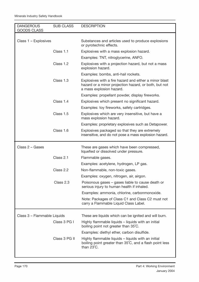
Page 170 Part 4: Working Environment
January 2004
Minerals Industry Safety Handbook
Part 4: Working Environment Page 171
January 2004
Minerals Industry Safety Handbook
DANGEROUS SUB CLASS DESCRIPTIONGOODS CLASS
Class 1 – Explosives Substances and articles used to produce explosions or pyrotechnic effects.
Class 1.1 Explosives with a mass explosion hazard.
Examples: TNT, nitroglycerine, ANFO.
Class 1.2 Explosives with a projection hazard, but not a mass explosion hazard.
Examples: bombs, anti-hail rockets.
Class 1.3 Explosives with a fire hazard and either a minor blast hazard or a minor projection hazard, or both, but not a mass explosion hazard.
Examples: propellant powder, display fireworks.
Class 1.4 Explosives which present no significant hazard.
Examples: toy fireworks, safety cartridges.
Class 1.5 Explosives which are very insensitive, but have a mass explosion hazard.
Examples: proprietary explosives such as Detapower.
Class 1.6 Explosives packaged so that they are extremely insensitive, and do not pose a mass explosion hazard.
Class 2 – Gases These are gases which have been compressed, liquefied or dissolved under pressure.
Class 2.1 Flammable gases.
Examples: acetylene, hydrogen, LP gas.
Class 2.2 Non-flammable, non-toxic gases.
Examples: oxygen, nitrogen, air, airgon.
Class 2.3 Poisonous gases – gases liable to cause death or serious injury to human health if inhaled.
Examples: ammonia, chlorine, carbonmonoxide.
Note: Packages of Class C1 and Class C2 must not carry a Flammable Liquid Class Label.
Class 3 – Flammable Liquids These are liquids which can be ignited and will burn.
Class 3 PG I Highly flammable liquids – liquids with an initial boiling point not greater than 35˚C.
Examples: diethyl ether, carbon disulfide.
Class 3 PG II Highly flammable liquids – liquids with an initial boiling point greater than 35˚C, and a flash point less than 23˚C.

Page 170 Part 4: Working Environment
January 2004
Minerals Industry Safety Handbook
Part 4: Working Environment Page 171
January 2004
Minerals Industry Safety Handbook
Infectious Substances
Examples: petrol, acetone, ethyl methyl ketone, ethanol.
Class 3 PG III Flammable liquids – liquids with a flash point of 23˚C or more, but less than or equal to 61˚C.
Examples: kerosene, mineral turpentine.
Class C1 Combustible liquids – liquids with a fire point less than their boiling point, and a flash point greater than 61˚C, but less than or equal to 150˚C.
Examples: dieseline, home heating oil.
Class C2 Combustible liquids – liquids with a fire point less than their boiling point, and a flash point greater than 150˚C.
Examples: lubricating oil, peanut oil.
Class 4 – Flammable Solids
Class 4.1 Flammable solids, self-reactive and related substances and desensitised explosives – solids easily ignited and readily combustible.
Examples: nitrocellulose, phosphorus, matches, hexamine.
Class 4.2 Substances liable to spontaneous combustion.
Examples: aluminium alkylís, white phosphorus.
Class 4.3 Substances which emit flammable gases when in contact with water.
Examples: aluminium phosphide, calcium carbide.
Class 5 – Oxidising Substances
Class 5.1 Oxidising agents.
Examples: hydrogen peroxide, calcium hypochlorite (dry pool chlorine), ammonium nitrate.
Class 5.2 Organic peroxides (liquid or solid).
Examples: methyl ethyl ketone peroxide, benzoyl peroxides, cumyl hydroperoxide.
Class 6 – Poisonous and These are poisonous (toxic) and infectious substances (excluding poisonous gases).

Page 172 Part 4: Working Environment
January 2004
Minerals Industry Safety Handbook
Part 4: Working Environment Page 173
January 2004
Minerals Industry Safety Handbook
Class 6.1(a) Poisonous substances – substances of PG I or PG II (which may be solids or liquids) which are liable to cause death or serious injury to human health if inhaled, swallowed or absorbed through the skin.
Examples: cyanides, arsenic compounds.
Class 6.1(b) Harmful (toxic) substances – substances of PG III which are harmful to human health if swallowed, inhaled or absorbed through the skin.
Examples: lead acetate.
Class 6.2 Infectious substances – substances containing micro-organisms that are known or believed to cause disease in humans or animals.
Examples: vaccines, pathology specimens.
(Contact the Health Department and the Environmental Protection Agency for more information)
Class 7 – Radioactive Substances These are materials or combinations of materials which spontaneously emit ionising radiation.
Examples: thorium nitrate, uranium hexaflouride.
(For more information on radioactive substances contact the Environmental Protection Agency)
Class 8 – Corrosives These are substances (either solids or liquids) which will damage living tissue, goods or equipment on contact, by chemical action. Examples: hydrochloric acid, sodium hypochlorite (liquid pool chlorine), sodium hydroxide (caustic soda).
Class 9 – Miscellaneous These are substances and articles which have potentially dangerous properties that are relatively minor, or are not covered by any of the classes already described. Examples: aerosols, polyester beads, polychlorinated biphenyls, Goods lithium batteries. The orange label indicates a vehicle is carryinmixed load of Dangerous Goods (for transport only).
Dangerous Goods

Page 172 Part 4: Working Environment
January 2004
Minerals Industry Safety Handbook
Part 4: Working Environment Page 173
January 2004
Minerals Industry Safety Handbook
4.15 FUMES
4.15.1 UNDERGROUND DIESEL FUMES
4.15.1.1 INTRODUCTION
This topic is dealt with in detail in a publication by the NSW Mineral Council: “Diesel Emissions in Underground Mines – Management and Control”. This is available as a printed version from the Minerals Council, or on their website. This section does not aim to reproduce the content of the Minerals Council document.
There are two basic means of controlling exposure of personnel to contaminants from diesel exhaust:
• minimising emissions, and
• providing adequate ventilation.
Both approaches are necessary, since toxic components are always present in diesel exhaust. If both approaches are implemented well, toxic components from the exhaust should be diluted to acceptable levels.
Testing is also necessary, to check the adequacy of control measures:
• diesel engines should be tested at regular intervals to detect deterioration in the quality of emissions, and
• surveys of ventilation will reveal inadequacies in the various work areas in the mine.
Since the ultimate goal is to minimise the exposure of personnel to toxic components, occasional surveys should be conducted of the levels of exposure experienced by some personnel in areas which are suspected of being the worst.
In addition to implementing control measures, and carrying out testing, it is highly desirable to incorporate an audit system, which will check and document that the controls and the testing are being implemented as they are designed to be, and that the results obtained are reliable.
4.15.1.2 PERSONAL EXPOSURE TO DIESEL EXHAUST
Gases
Limits for diesel exhaust gas exposure
Exposure limits for a number of air contaminants, including some produced by diesel engines, are given in the NSW Minerals Council publication. Note the overriding requirement that exposure to contaminants not specified in the list should not be present in concentrations, which exceed limits prescribed by Worksafe.
The thinking in some areas of occupational health is that toxic contaminants have an additive effect. On this basis, if one component is present in a concentration equal to its exposure limit, no other contaminant should be present; if several components are present, each should be well below its exposure limit. Each limit should therefore be regarded as a maximum, and lower concentrations should be the aim.
Sampling air for diesel exhaust exposure
At the low concentrations, which must be measured to check on personal exposure, it is not possible to collect samples in bags and store them. If this is tried, the contaminants in the air will coat the walls of the bag, leading to noticeably measured low results.
Gas detector tubes are a practical means of measuring personal exposure. They are available for a wide range of gases, they do not require the sample to be stored, and they give a good indication (but not a precise measurement) of the level of exposure. One drawback of these tubes is that they cannot be calibrated, because each tube is used once only.
There are portable instruments which measure some gases at the low levels required. Most of these are ‘electrochemical’, and their measurement cells deteriorate gradually; they must be re-calibrated periodically, and the cells
Page 174 Part 4: Working Environment
January 2004
Minerals Industry Safety Handbook
Part 4: Working Environment Page 175
January 2004
Minerals Industry Safety Handbook
replaced when they can no longer be adjusted to read correctly.
Analysis of air samples
If the testing is done by detector tube or portable analyser, there is no further analysis to be done. If samples have been collected using other techniques (impinger etc), the analysis will normally be completed by the laboratory which specified the sampling method.
Airborne particles
Particles from diesel exhaust are often referred to as “diesel particulate matter” (DPM). They are basically carbon, but carry gaseous components of the exhaust adsorbed onto the surface, making them considerably more dangerous than ordinary carbon. They are an obvious air contaminant from a diesel engine, and are associated with poor combustion of fuel. A turbocharged engine is especially likely to emit particles (smoke) when the engine is accelerated; this is because the engine is commonly over-fuelled for a few seconds until the turbocharger increases the air available for combustion.
Target levels for airborne diesel particulates
Mine atmospheres should not contain more than 0.2mg/m3 of diesel particulate matter (soot) being the level that has been identified that effects of irritation are minimal – NSW Minerals Council 1999. This equates approximately to the proposed workplace limit of 0.16 mg/m3 total carbonfor metalliferous mines from the USA Mine Safety and Health Administration.
Sampling airborne diesel particulates
Personal exposure to airborne diesel particulates is measured in the same way as other airborne dust particles, but using a glass-fibre filter. If the correct filter is used, and in the absence of other sources of carbon such as coal dust, the two determinations (airborne dust and airborne diesel particulates) may be carried out on the one filter. If coal dust is present, special sampling techniques may allow diesel particulates to be identified and measured separately because of their particle size.
The details of a sampling method are given in the section on Airborne Dust Monitoring.
Analysis of airborne diesel particulates
Where no other carbonaceous (carbon-bearing) material is present, the diesel particulates collected on a filter can be oxidised, and the loss in weight determined. However sulphide ores can also be oxidised, so the process is carried out in a plasma ashing furnace, which operates at a low temperature and uses low-pressure ozone to oxidise carbon without affecting sulphides. The residue on the filter can then be used to determine exposure to other respirable dust.
Special sampling methods must be are used in coal mines, because the coal dust and the diesel particulates are both basically carbon.
Details of the method are given in the section on Airborne Dust Monitoring.
4.15.1.3 VENTILATION AIRFLOW
Maximum engine exhaust emissions
The raw exhaust of diesel engines discharging to atmosphere below ground should not contain contaminants with concentrations exceeding the values required by each State or Terriroty.
Determination of air flow
For the purpose of designing overall mine air flows, it is common for a minimum quantity of 0.06 to 0.1 m3/s/kW to be used. A sample calculation for determining airflow about a diesel engine is shown in Appendix 4.5.
The airflows suggested as necessary to ventilate diesel engines are based on the maximum concentrations of contaminants in the raw exhaust, and the dilutions necessary to reduce these to exposure standards. Newer engine control technology may be capable of substantially reducing the emissions from engines.
Older engines at times produce emissions higher than those recommended. It should be remembered that exhaust gases are analysed under steady-state conditions, but a turbocharged engine under acceleration may briefly exceed the

Page 174 Part 4: Working Environment
January 2004
Minerals Industry Safety Handbook
Part 4: Working Environment Page 175
January 2004
Minerals Industry Safety Handbook
measured values by a considerable margin. The new engine control technology prevents emissions of carbon monoxide, oxides of nitrogen and smoke ever being as high as previously measured.
If lower airflow requirements are to be set, they should be based on a careful analysis of the machine in operation. It may be that the limiting factors will be heat production, or carbon dioxide emissions.
Allowance should also be made for local concentrations around the engine which will be higher than the calculated average diluted exhaust. Especially at lower ventilation rates, it may be necessary to assist mixing of exhaust with ventilation air. The engine fan can assist if the exhaust gas exits at a suitable point, or some kind of ‘fume dilutor’ may be required.
4.15.1.4 CONTROL MEASURES FOR DIESEL
EMISSIONS
It has been the requirement in the past that engines used underground should be fitted with an exhaust conditioner, although engines below 100kW have been exempt from this where the raw exhaust contained less than 1,000 parts per million of carbon monoxide.
Exhaust conditioners can be of several types:
• water scrubbers are still very common in coal mines, but are now rarely used in metal mines; they have little effect on the gases in exhaust emissions, but may significantly reduce particulates;
• catalytic converters when clean can substantially reduce carbon monoxide, aldehydes and hydrocarbon emissions; and
• ceramic and other particulate filters are extremely effective in removing smoke from the exhaust stream and also provides catalytic action to reduce CO2 and aldehydes.
Other control measures include:
• appropriate selection of engine type, for best emissions – pre-combustion engines (indirect injection) are generally much cleaner than direct injection engines, with electronic engine-management systems are becoming available on diesel’s;
• selection of fuel, both to obtain cleaner emissions and ensure a low sulphur content (a limit of 0.3% sulphur is specified by some authorities, and Federal Government legislation will lower the limit to 0.05% for automotive diesel fuel);
• careful storage, handling and dispensing of fuel to minimise contamination;
• frequent maintenance of the air intake system, to ensure that filters do not become blocked;
• on turbocharged engines, fitting and correctly adjusting a smoke control device (such as an air/fuel ratio control device) to minimise diesel particulate matter; and
• training operators of turbocharged machines to open the throttle progressively (over a couple of seconds) rather than suddenly.
4.15.1.5 DIRECT TESTING OF GASES IN DIESEL EXHAUST
Gases in diesel exhaust
Diesel engines emit several different gaseous toxic components, only a few of which have prescribed limits: carbon monoxide, and the two oxides of nitrogen – nitric oxide and nitrogen dioxide. These are not the main irritant components of diesel exhaust, but they are recognised as being toxic, and are relatively easy to measure.
The main irritant components are members of the aldehyde class of compounds, some of which are found in diesel exhaust. Only one formaldehyde, not the most irritant one, can be readily measured with gas detector tubes. A laboratory process similar to that described earlier in “Sampling of Air for Diesel Exhaust Exposure” can be used; the sampling is much quicker, because of the higher concentrations, but the laboratory techniques are far from simple. Routine sampling for aldehydes is therefore not feasible.
The goal then is to measure gases which can be tested easily, and which will give a good assessment of the clean operation of the engine.
When a laboratory tests an engine it will measure carbon dioxide in addition to the other gases. This is mainly to determine the operating

Page 176 Part 4: Working Environment
January 2004
Minerals Industry Safety Handbook
Part 4: Working Environment Page 177
January 2004
Minerals Industry Safety Handbook
condition of the engine at the time of the test and, in particular, the ratio of fuel to air. This could also be measured by gas detector tube if required.
The way in which the exhaust is sampled will depend on the way in which it is to be analysed. But there is a great advantage in using a bag to collect samples even when the sample is to be analysed immediately.
Details of a practical method of collecting exhaust gas in a bag, whether for immediate analysis or for temporary storage, are given in Appendix 4.6: “Using Bags to Collect Samples”.
Using gas detector tubes
Where gas detector tubes are being used, the following points should be observed:
• Check the integrity of the pump by inserting a new detector tube in the pump, squeezing the pump, and watching for the pump to expand; if there is noticeable movement, the pump needs servicing.
• Follow the directions of the tube manufacturer, taking care to comply with any temperature requirements.
• Allow the pump to expand fully between strokes; this is indicated by either a chain under tension, or an indicator on the pump.
• Many tubes have two scales – a high range with few pump strokes, and a lower range with more pump strokes. Operate the pump for the smaller number of strokes first then, without disconnecting from the sample bag or tube, observe the reading on the appropriate scale. If the reading is reasonably low on this scale, continue with the extra pumps for the low scale, and read the tube on this scale.
• Some colour changes are difficult to read, and the end point is sometimes uneven. For a final reading, rotate the tube in the hand in the best available lighting to find the average position of the last discolouration of the tube.
If portable or laboratory analysers are to be used, sample must be suitably conditioned (filtered, and
water removed) to prevent the instrument being contaminated. Follow the instructions of the supplier.
Particulates
The problem of smoke has been discussed briefly in “Airborne Particles”, under the section on Personal Exposure to Diesel Exhaust. While the transient (short-term) emission of smoke from a turbo-charged engine can be a major contributor to air contamination, it is not easy to measure. The simple field measurement of exhaust smoke is done on an engine under constant load (as with the gas measurements).
An alternative method, which is capable of monitoring the transient smoke from turbocharged engines on acceleration, uses an opacimeter – an instrument which directly measures the “blackness” of exhaust emissions. One type of opacimeter is mounted across the end of the exhaust pipe, and readings are displayed digitally and output electrically on a readout unit.
Limits
A standard for smoke emissions under constant load is still being determined, but it appears likely that, for a time, the measurements will be made with a Bosch smoke meter. This draws a fixed volume of exhaust through a filter paper, and a separate device is later used to measure the discolouration of the paper on a scale from 0 (no change) to 10 (completely black). The test is quite sensitive, and very clean exhausts can give values around 0.2, while 3 denotes a rather dirty exhaust.
A standard for on-road vehicles is depicted in the following graph. There is a strong case for working to lower limits in the underground mining environment.
Sampling and measurement
A procedure for sampling and measuring smoke emissions is given in Appendix 4.7, Measuring Smoke Emissions with the Bosch Smoke Meter.
Page 176 Part 4: Working Environment
January 2004
Minerals Industry Safety Handbook
Part 4: Working Environment Page 177
January 2004
Minerals Industry Safety Handbook
4.15.1.6 APPENDICES
APPENDIX 4.5
Calculation of airflow about a diesel engine
It is common for a minimum airflow quantity of 0.06 to 0.1 m3/s to be applied for each kW of power employed in a part of a mine. As an example, if engines totalling 300 kW rated power are to be used in a part of a mine, an airflow of 300*0.06, or 18 mΔ/s or more, should be provided.
APPENDIX 4.6
Using bags to collect samples
A very effective bag for collecting exhaust gas samples, or any other gas samples which can be stored in bags, is the liner from the familiar wine cask – emptied of its intended contents. These bags have a capacity of about 4.5 litres. When purchased as a gas sampling bag, they come fitted with a more appropriate connection. They can be protected against rough handling by a denim cover.
Equipment required
• one (1) sample bag for each sample or, if samples are to be stored, two (2) bags per sample, and a source of dry nitrogen;
• one (1) copper cooling coil or other device which will allow exhaust gas to cool to a temperature at which it can be passed through a flexible tube (of vinyl or rubber); the cooling device needs to be fitted to the sampling connection on the exhaust system, usually by a flare fitting;
• a flexible tube to connect the cooling device to the sample bag; this may be of vinyl or rubber, and not too long, but long enough to allow the sampler to stand in a safe position while the machine is operated on load; a push-on connector may be needed to connect the line to the bag;
• a pump, such as a large hand aspirator bulb, may be useful to assist in the rapid filling of the sample bag; and
• an appropriate method of analysis; this could be gas detector tubes or portable analyser(s), or larger laboratory-style analysers.
Procedure
• Decide how the engine can best be placed under load, and make sure that the machine operator is aware of what is required.
• Consider where the sampler should be positioned, and safety aspects, such as:
– is the sampler adequately protected against noise?
– can the machine slew sideways if a wheel slips?
– what would happen if the sampler loses footing?
– will there be adequate communication between sampler and operator with the noise of the machine operating on load, or should a third person be involved?
• Empty the sample bag either:
– by rolling it up diagonally, starting from the corner furthest from the outlet; or
– by pumping it empty with an aspirator bulb. (However, if using a pump, be careful that the bag does actually empty; the bag can block the outlet internally, preventing a pump from drawing out the remaining gas.)
• Connect the cooling coil to the exhaust sample connection, and the tube to the cooling coil.
• Place the engine under load; allow a few seconds after it has stabilised for the tube to flush, then connect the bag to the sample tube and allow it to almost fill (or pump it if using a pump).
• Crimp the tube connection, and take the machine off load.
If samples will not be analysed within 10 minutes, they must be taken using a two-bag system, as follows (or some other equally effective means of preventing loss of oxides of nitrogen):

Page 178 Part 4: Working Environment
January 2004
Minerals Industry Safety Handbook
Part 4: Working Environment Page 179
January 2004
Minerals Industry Safety Handbook
• Before commencing sampling, at least half-fill an empty sample bag with nitrogen.
• Collect raw exhaust from the engine in a second (empty) bag, in the manner described above.
• Immediately connect the two bags together, and squeeze some of the raw exhaust into the bag containing nitrogen.
• Seal both bags.
Loss of oxides of nitrogen is much slower in the dilute sample, and when both bags are analysed, the correct original value can be determined using the formula:
Co in rawCorrect NOx = NOx in dilute sample
sample x Co in dilute sample
Measuring smoke emissions with the Bosch smoke meter.
Sampling
A sample could be taken from a connection on the exhaust system, but it would be more usual to take it from the end of the exhaust pipe. (This may not be feasible if a water scrubber is fitted.)
• Clamp the probe (supplied with the Bosch instrument) on the end of the exhaust, and operate the engine under load.
• Depress the plunger, and load the sampling device with a clean filter paper.
• Operate the engine under load as described in the section on exhaust gases, and when it is stable, squeeze the aspirator bulb to release the plunger.
• Take the engine off load; remove the filter paper and either measure immediately or label and store in a clean container for measurement later.
Measurement
The measurement of the filter paper is carried out in accordance with the instruction supplied with the Bosch meter. The following points may be helpful:
• The background has an effect on the measurement. Several unused filter papers form a white background which will give consistent readings.
• Set the zero on the instrument using a clean filter paper. Hold the ‘O’ button for several seconds while the instrument adjusts the zero.
• Take an average of the reading on a filter by measuring at about three points scattered around the centre.
• There may be a slight difference between readings on the two sides of the paper. If unsure which was the face exposed to the exhaust, measure both sides and take the higher reading. (Marks on the paper can give clues as to which way it was mounted in the sampling device.)
REFERENCE DOCUMENTS
Diesel Emissions in Underground Mines – Management and Control: NSW Minerals Council.
Diesel Engine Systems for Underground Coal Mines: AS 3584, – 1991.
Guidelines for Diesel and Operator Environment Testing in Underground Coal Mines: MDG29, NSW Department of Mineral Resources.
Diesel Particulate in Coal mines – Questions and Answers: Joint Coal Board (now part of Coal Services Pty Ltd).
Australian Design Rule 30 for Diesel Exhaust Smoke Emissions, issued by the Department of Transport, February 1984.

Page 178 Part 4: Working Environment
January 2004
Minerals Industry Safety Handbook
Part 4: Working Environment Page 179
January 2004
Minerals Industry Safety Handbook
4.16 EXPLOSIVES USE
4.16.1 GENERAL
Explosives should be manufactured, handled, stored, conveyed and used in or about mines in a manner which is safe.
The usage, storage, manufacture and conveyance of explosives in or about mines should generally be in accordance with Australian Standards.
Explosives should be protected from fire, impact, loss, spillage, deterioration, theft and accidental initiation so as to minimise the risk to the safety of any person.
No one should retain, remove or otherwise dispose of explosives other than in the proper running of the mine. Theft and misuse is treated very seriously.
The mine operator need to designate people to use and handle explosives.
4.16.2 EXPLOSIVES MANAGEMENT
4.16.2.1 PERSONS HANDLING EXPLOSIVES
No one under the age of 18 years should be allowed to handle, charge or fire explosives.
There should be no smoking while handling, charging or using explosives, nor within the vicinity of explosives, initiating system, or accessories.
There should only be enough explosives on hand to meet the shift’s requirements.
4.16.2.2 STORAGE
Magazines should be of a construction and in a location which minimises risks of theft, fire and impact, and which minimises the effect of any detonation during storage, and also minimises any adverse impact from storage. The maximum quantity of explosives should be displayed on the door of the magazine or storage area and adequate ventilation provided.
Detonators and explosives should be stored in separate magazines. If explosives and detonators are stored in the same magazine, they should be
kept separated by a solid intervening fireproof barrier.
Igniter cord, safety fuse and fuse lighters must be kept in a cool, dry place away from fire and separate from other explosives and detonators.
A means of maintaining an accurate record of all incoming, outgoing and current stocks of explosives should be instituted. This may consist of a board, magazine log book, or other means.
The theft or loss of explosives or any unaccountable stock shortages of explosives should be reported immediately to an Inspector and to Police.
The following should be considered in the design and construction of underground magazines.
• the magazine should be located away from any shaft or main mine access;
• the magazine should be located away from essential infrastructure, such as crib rooms and workshops;
• the magazine should be located so that the possible effects of an explosion will not adversely impact upon winders, electrical substations, pump stations, ventilation equipment or other important installations or equipment;
• fumes from any accidental fire or explosion should travel away from where people are working and away from escape routes;
• any existing boreholes which may intersect the magazine walls must be securely plugged;
• the magazine area must be kept free of water and away from drainage dumps;
• the magazine area and surrounds must be kept clear, swept regularly and unencumbered with combustible materials;
• the quantity of explosives stored in underground magazines should be kept to a minimum consistent with the safe movement of explosives. The amount required for one week’s supply is a useful guide;
• vehicles should have to make at least one 90 degree turn to access a magazine to minimise hazards of out of control vehicles;
• magazine doors shall open outwards; and

Page 180 Part 4: Working Environment
January 2004
Minerals Industry Safety Handbook
Part 4: Working Environment Page 181
January 2004
Minerals Industry Safety Handbook
• the security requirements for doors of underground magazines and locking mechanisms must be equivalent to other magazine types.
4.16.2.3 SIGNAGE
Ensure that all open and accessible places are fenced off with appropriate warning signs erected. The signs should be durable, easily identifiable and positioned off the ground. Standard danger signs are preferred and should clearly indicate the nature of the hazard, such as “Charged Face No Unauthorised Entry” or “Explosives in Use No Unauthorised Entry”.
Appropriate signage should be displayed on all vehicles and equipment used in explosives transportation and charging activities.
Temporary storage of explosives should be guarded and signs erected. A flashing light could also be used to clearly indicate its location.
4.16.2.4 TRANSPORT
Explosives when taken from a magazine or supply point for use should be conveyed directly to the workings in a securely covered case or canister or other suitable container in a manner which minimises risks of initiation.
4.16.3 CHARGING AND FIRING
4.16.3.1 CHARGING OF EXPLOSIVES
It is very important to dissipate any electrostatic charges generated whilst pneumatic charging with explosives.
Be aware that charges fired inside or in contact with any piece of timber below ground at a mine may lead to a fire. A watch may need to be kept to detect any smouldering of the timber.
Before any hole is charged it should be checked and cleaned out.
4.16.3.2 MASS BLASTS
Mass blasts are defined as those where the number of charges to be fired or the quantity of explosives to be used is such that charging and firing cannot be completed within one working shift.
Control systems may need to be developed to record the place, amount of explosives and dates of charging and firing for each blast.
It is important that the type of explosives selected and used will not deteriorate significantly during the charging process and period prior to detonation.
Signs and temporary barricades may need to be erected to restrict entry and warn of danger.
Vehicles being used in a charged area must be incapable of causing pre-ignition of explosive charges through heat or stray current. The use of radio communication equipment at the mine should be strictly controlled to prevent pre-ignition.
The firing point should be chosen to avoid air blasts, secondary explosions and fly rock damage.
4.16.3.3 INITIATION OF EXPLOSIVES
A shift coming on should not commence work until a proper check of the previous shift’s firing has occurred and the workplace is declared safe.
Where different faces underground are fired at the same time, parties stationed in a more remote position from a safe area should fire first.
Good communication between the parties is essential to ensure the safety of all personnel involved. Firing should be done at designated blasting times and all persons should withdraw to a safe area.
Electric initiation
Advice on equipment, precautions, tests and procedures for electric initiation is outlined in AS 2187.
Immediately before firing, the series circuit should be tested by an ohmmeter or other method to determine continuity and appropriate resistance. It should be assumed when testing that an explosion might occur and precautions must be taken to choose the test location carefully.
Blasting machines
An exploder should be tested at regular intervals to ensure that it is fit for its designed task.

Page 180 Part 4: Working Environment
January 2004
Minerals Industry Safety Handbook
Part 4: Working Environment Page 181
January 2004
Minerals Industry Safety Handbook
Use of mains firing
Electricity from ordinary power or lighting cables should not normally be used for firing shots.
However, where mains power (electricity) is used:
• a firing switch should be installed between the source of power (electricity) and the firing conductors, and insulated and protected so as to ensure a total absence of current leakage into the firing cables except when the switch is closed;
• the firing and any other switch used should be placed in a fixed switch box, which is provided with a lock and so constructed that it cannot shut unless the switch is in the short circuit position;
• there should be only one key issued for use for each switch box and kept in the custody of an authorised person, and in no circumstance should it pass from that person’s custody while on duty;
• firing conductors should be provided and fitted with plugs capable of connecting them to appropriate sockets in the switching apparatus;
• wiring, switch, switch box or other equipment of a firing circuit should not be earthed;
• the firing switch should not be connected to the source of power (electricity) nor should any electrical contact be made to the firing switch until all people have left for a safe place;
• prior to connecting power (electricity) to the firing switch, the circuit to each of the explosive charges should be tested from a safe place; and
• immediately after firing or attempting to fire the charge or charges, the shotfirer should disconnect the firing conductors from the switching apparatus and lock the switch boxes.
4.16.4 HAZARDS
4.16.4.1 STORMS
Procedures should be developed for times when an electrical or dust storm, of sufficient intensity
to be dangerous, appears imminent. Shaft sinking and adit operations are particularly at risk from conducted lightning strikes. The procedures might include:
• all people working in or near an area where explosives are stored or manufactured should be withdrawn to a safe area;
• all vehicles conveying explosives should be returned to a safe place until the storm activity has passed; and
• explosives and detonators which are not yet used should be returned to the magazines.
4.16.4.2 MISFIRES
When a hole is known to have misfired and is left unattended, a barricade or other obstruction with a danger notice should be placed to advertise the misfire and to prevent an inexperienced person interfering with the hazards. A safe system of work should be developed to handle misfires and include:
• re-entry time for misfires as per manufacturers recommendations;
• decision process on refiring;
• refiring process;
• ground control requirements;
• recovery process if not refired;
• reporting and recording process; and
• notification to supplier.
4.16.4.3 DUST
Blasting should be carried out in open cut and quarry operations in such a way that dust from the blast does not create a concern for neighbours.
4.16.4.4 ENTRY AFTER BLASTING
Fumes and toxic gases arising from the explosion should have been effectively dispersed before re-entry of any persons. Senses of sight and smell should be sufficient for most determinations, but oxygen deficiency is a real risk, particularly in small underground headings such as rises, and mine atmospheres should be tested. A safe system

Page 182 Part 4: Working Environment
January 2004
Minerals Industry Safety Handbook
Part 4: Working Environment Page 183
January 2004
Minerals Industry Safety Handbook
of work should be developed for re-entry and include:
• no one to enter the underground workings on the exhaust side of the ventilation until the ventilation circuit has been cleared of fumes and dust;
• required time for dust and fume clearance;
• method or system to ensure breathable air quality;
• assessment of blast results;
• hazards identified, rectified or barricaded and checked for misfires;
• visual inspection requirements of excavation or pit walls in the blast zone;
• clearance communication process;
• persons authorised to conduct re-entry; and
• contingency plan for non-completion of the re-entry procedure.
Where there is the possibility of voids in the blast there should be special procedures for re-entry.
4.16.4.5 DISPOSAL OF UNWANTED
EXPLOSIVES
Old or deteriorated explosives must be destroyed by proper procedures, bearing in mind the recommendations of the manufacturer.
All sites should develop a procedure for the safe disposal or destruction of explosives.
Generally explosives may be destroyed by either detonation, or by burning. They must never be buried. Refer to AS 2187 Explosives: Storage, transport and use.
4.16.5 SULPHIDE ORE DUST EXPLOSIONS
The operating mechanisms of sulphide dust explosions (SDE) are not presently fully understood. It is, however, important that the problems of such explosions are appreciated so that operating practices, in areas prone to such explosions, can be implemented. A fundamental requirement of this is training personnel to
recognise areas which are likely to support SDE, and the various methods available to either prevent SDE occurring or to minimise the effects of such explosions to people or property. A system of reporting and documentation of such explosions should also be established.
Operators should understand what an SDE is; how SDEs occur; the dangers of such explosions, including the effects of the gaseous products of such explosions; and should have knowledge of appropriate practices which should be used in areas likely to support such explosions. Additionally, operators should be able to identify areas which may support SDE, as well as to recognise both the gaseous and particular products of SDE. They should be aware of any system of reporting SDE occurrences and understand the importance of such reporting. They should also be aware of the use and limitations of the various self rescuers available.
4.16.5.1 PREDICTION
The nature of ore capable of generating an SDE is not clearly defined, but is related to the sulphur content of the ore and its mineralogy, including grain size. Ores containing appreciable quantities of pyrite and pyrrhotite are considered to be particularly at risk. Many other sulphide dusts are known to explode. As a general rule of thumb, any ore containing a sulphur content of 20 percent or more should be regarded as potentially explosive and precautionary measures should be implemented. Some ore, due to its mineralogy, will produce a dust of disproportionately high sulphur content. SDEs have occurred in orebodies with a sulphur content as low as 11 percent. Operational experience will identify mineralogical zones in an orebody where the risk of SDE is high.
Prediction of SDE potential areas should start with the collection of exploratory mineralogy data, which can be manipulated by geostatistical methods to define areas of high sulphur content. These areas should be clearly marked on geological maps of the orebody so that precautionary measures can be implemented during mining. As further data are collected, this mapping of SDE potential areas can be further clarified.
Page 182 Part 4: Working Environment
January 2004
Minerals Industry Safety Handbook
Part 4: Working Environment Page 183
January 2004
Minerals Industry Safety Handbook
Experience obtained in mining the orebody will reveal high risk areas for SDE. Additionally, examination of the ore faces during mining of high risk areas will enable the collection of detailed mineralogical data, which can later be used to help predict SDE. These data should also be recorded on geological plans and will be of great help in any post-explosion evaluation. Any occurrences of SDE should be fully documented and marked on mine plans, so that trends in SDE potential within an orebody can be observed. This documentation should start with reporting of SDE occurrences on shift report forms. Further documentation should be comprehensive, detailing all aspects of the blasting method employed, explosives used and the effects of the explosion. Details of mineralogy and explosion products should be included if possible.
4.16.5.2 PREVENTION
The classical explosion triangle shows that fuel, oxygen and an ignition source are required for an explosion to occur. Inhibiting any two components in the system will prevent an explosion.
Various techniques have been used to prevent and limit the occurrence of SDEs. Research work to date has shown that use of limestone, short delays in blasting and water sprays are all ineffective in preventing explosions. However, dust explosions can be prevented by:
• covering all exposed explosives; and
• using adequate stemming.
The research has also shown the importance and value of monitoring for sulphur dioxide following all blasting activities, no matter how small. It has also shown that controls which might have been added to the earlier controls (which were generally regarded as insufficient) would not have been effective. These possibilities included:
• limiting all blasts to a maximum duration of 120 milliseconds;
• using permitted explosives; and
• clearing the mine of all personnel before any blasting or, alternatively, providing fresh air bases and oxygen self-rescuers.
What has not been shown yet by research includes:
• detonating cord restrictions;
• stemming specifications;
• enclosing of all explosives (including detonating cord and detonators);
• sulphur dioxide monitoring procedures; and
• popping or plastering hazards, especially in drawpoints and crushers.
A single hole can cause an SDE. There is no value therefore in limiting blasting to short delay detonators or to any particular duration of blast.
While information is now much better than four years ago, there is still a need to take a conservative approach. It is reasonably certain that the very low strength signal tube will not cause a dust explosion, while a cord of 3.75 g/m can cause a dust explosion. It is also reasonably certain that stemming of at least 600 mm (0.6 m) in length in standard development rounds will prevent a dust explosion emanating from stemmed blastholes, but stemming requirements for stope blasting are not known.
Popping activities are strong possibilities for dust explosions and probably should only take place with normal stope firings when the mine is cleared. Proper monitoring of exhaust air will detect a dust explosion, which is not detected otherwise, and allow for precautions to be taken before return to work.
The use of stone dust to make the combustible sulphide dust inert has been tried. However, the quantities of stone dust required are prohibitively large. In addition to this, difficulties in dispersing this dust make the method impractical. Consequently, this method should not be used to prevent or inhibit SDE.
A method used in controlling SDE is washing down of exposed surfaces. The use of air-water sprays alone is not sufficient and sprays have questionable value under any circumstance.
Washing down exposed surfaces does not prevent the development of primary dust explosions caused by ignition of the dust cloud developed during blasting, but does help to lower the
Page 184 Part 4: Working Environment
January 2004
Minerals Industry Safety Handbook
Part 4: Working Environment Page 185
January 2004
Minerals Industry Safety Handbook
availability of fuel for a secondary explosion, thus preventing propagation of an explosion through the mine workings. Caution should be taken when washing down because water jets may cause some dust dispersion.
The surfaces of cut-and-fill stopes and development headings can be cleaned with a water jet using normal underground water pressure. Washing down a large open stope is difficult due to the inaccessibility and size of the roof, walls and floor. A high pressure water jet may be required to reach difficult locations in an open stope and the design of new stopes in high risk ore bodies should incorporate access drives at selected points to facilitate washing down the surfaces. Preferably these accesses would be drill drives.
To have any effect, washing down should be extended to, say, 20 m from the face in development headings, and at least 20 m on both the intake and return airways of a stope. Always consider the potential of an explosion to propagate through the workings, particularly in massive ore bodies. Washing down should be performed immediately prior to charging and sufficiently close to firing time to ensure that the process is effective.
Water sprayed on the walls and floors of a stope reduces the likelihood of an explosion in previously deposited dust and, due to the agglomeration of the wet particles, tends to reduce the mass of dust raised when broken rock hits the walls and floor of the stope. Airborne dust may also be suppressed if the spray droplets are small enough. The presence of a dense cloud of micro-droplets of water within a stope may quench the flame of a potential ignition source or the flame front of a developing explosion, but more work needs to be done to determine whether this method provides real protection.
If water sprays are used, they should be located so that a dense fog of water persists over the blast area.
In a development heading, sprays should be directed at the face. Similarly, water sprays for stopes should cover the blast area. These sprays in open stopes should be positioned in draw points and drill drives, and it would be better to set up sprays to create a fog within the stope.
Additional air-water sprays could be used in the drill drives and extraction levels of open stopes as barriers. Such semi-permanent installations would be appropriate. These should be located a minimum of 15 m and no further than 45 m on both the intake and return air sides. Water sprays help to dissolve sulphur dioxide (SO2) produced in an SDE, which will result in sulphurous acid forming. This sulphurous acid will slowly oxidise to produce sulphuric acid.
Watering down practices and the use of air-water sprays may also be used for secondary blasting. This includes popping of oversize material, bombing of drawpoints and ore-passes, and any other secondary blasting which is performed in areas capable of supporting an SDE. This includes ore handling facilities. Always consider the potential of a secondary SDE and implement preventative measures.
Some thought has been given to removing oxygen from the explosion triangle. When blasting, the air in the blast area is displaced to some degree by the inert explosion gases produced during detonation of high explosives. If the oxygen content of the air is reduced to below 12 percent, it is unlikely that an SDE will occur. The volume of gases produced in a development blast are not generally sufficient to displace the air fast enough to reduce the oxygen content in order to prevent an SDE. However, in open stopes, during the early stages of production, the void volume is comparatively small, and a small number of charged holes may provide sufficient inert gas to reduce the oxygen content below the minimum concentration necessary for an explosion when fired. As the stope is mined out, the void space increases and a large mass of explosive will be required to produce a sufficient volume of inert gases to prevent an explosion. Thus the firing of multiple rows of holes is more likely to produce an inert atmosphere. Paradoxically, watering down of the stope is comparatively easy when the stope void is small and becomes more difficult as the stope void increases in size. The displacement of oxygen by inert explosion gases cannot be relied upon to inhibit an SDE.

Page 184 Part 4: Working Environment
January 2004
Minerals Industry Safety Handbook
Part 4: Working Environment Page 185
January 2004
Minerals Industry Safety Handbook
Blasting practices are also important when firing in areas which have potential for SDEs. Lower detonation velocity explosives may assist in preventing an SDE, but this is not yet determined.
The practice of using stone dust for stemming is ineffective. Not only is it an ineffective stemming material, but it may lead to the development of higher exhaust temperatures than would be developed if comparatively coarse stemming is used. Furthermore, multiple firings of stopes and headings should be restricted, as this practice may result in the formation of an explosive dust cloud in areas nearby to the blast which have yet to be fired.
Some recent experiences would indicate that standard detonating cord may cause an SDE. Consequently, 10 g detonating cord should not be used in drawpoints, ore passes or normal firings where the sulphur content is high.
4.16.5.3 DETECTION
All firings in SDE potential areas should be detonated electrically from an approved firing box in an approved location, only after all personnel have retreated to a safe location. Consider the gaseous products of an SDE, their effect on the ventilation system and the potential for an explosion propagating through a massive sulphide orebody, when designating these approved locations.
An SDE will not always be detected at a firing point. If an SDE has occurred, it is preferable to detect its occurrence remotely before personnel return to their working areas. This can be achieved through the use of SO2 detectors located in return airways. Exhaust air can be monitored either through the use of permanent gas monitoring systems, or manually through the use of portable SO2 detectors or gas detection tubes. Small dust explosions may not generate sufficient quantities of SO2 to be detected in return airways if the detection equipment is not sufficiently sensitive.
Remote detection can not indicate precisely where a SDE has occurred. Thus, working areas need to be inspected before personnel return to their working places. Inspections should be made by at least two persons, one of them being a supervisor.
Portable SO2 detectors or gas detection tubes should be used for sampling mine air. If a contaminated atmosphere is encountered it will be apparent due to the pungent odour of SO2 and the offensive odour of hydrogen sulphide (H2S). Olfactory warning (detecting a smell) can be lost if H2S is present in concentrations in excess of 50 ppm (parts per million). Thus the smell of the gases cannot be relied upon to give adequate warning of a toxic atmosphere.
4.16.5.4 RE-ENTRY
Danger exists to all personnel entering areas which are highly contaminated. Consequently, inspections should involve the gradual entry into potentially contaminated atmospheres, combined with regular testing of mine air. Persons inspecting should also be equipped with either filter self rescuers designed for SO2-contaminated atmospheres or self-contained self rescuers. No other underground personnel should be allowed to return to their working areas until those areas have been checked.
It is impracticable to check all underground areas for sulphur-bearing gases. However, the danger exists of these gases accumulating in an area away from the explosion site. Thus it is important that fresh air bases are established regularly throughout the mine workings and that self rescuers are available at these bases. Self-c ontained self rescuers, rather than filter self rescuers for SO2 atmospheres, are a superior choice of equipment. This is because they can be used in other contaminated atmospheres, as well as highly contaminated atmospheres where the toxic gas concentrations are so high as to make the filter self rescuer useless. The issuing of all-purpose, self-contained self rescuers to underground personnel is prudent.
Clearing of fumes relies upon effective ventilation. As a result of an SDE, large volumes of gases are generated which could reverse ventilation in a local area, or on a large scale depending upon the magnitude of the explosion. This can cause tripping of fans, particularly those used for auxiliary ventilation in development headings and stopes. If this occurs, long delays will be experienced in clearing of fumes unless the fans can be restarted. To avoid the need for
Page 186 Part 4: Working Environment
January 2004
Minerals Industry Safety Handbook
Part 4: Working Environment Page 187
January 2004
Minerals Industry Safety Handbook
personnel to enter a contaminated atmosphere, fans or fan electrical equipment should be located in main airways. The process used for fan re-starting should follow the same precautionary measures as used in checking working areas.
The mines evacuation procedure should cater for the possibility of an SDE. Additionally, the firefighting and rescue equipment should be selected so that an H2S or an SO2 atmosphere can be detected and entered. Personnel should be fully trained to deal with such an event, including how to treat others affected by exposure to H2S or SO2.
4.16.5.5 TRAINING
Shotfirers and charging crews should be trained in the same way as operators, but should also be aware of the correct methods of firing in SDE-prone areas, especially covering any exposed explosive and using adequate stemming. Charging crews should be fully trained in the various preventative techniques employed, especially hosing down.
Supervisors should be trained in the same way as charging crews, but should also be responsible for ensuring that the correct preventative measures are implemented. Additionally, supervisors should be aware of the ventilation requirements for areas prone to SDE and of the effects that such explosions can have on the ventilation system. Supervisors represent the first line in documenting SDEs and any such explosions should be investigated and documented.
Engineers responsible for ventilation should have a full knowledge of both the gaseous and particulate products of SDE and the effects of such explosions on the ventilation system. An efficient sulphur dioxide monitoring system will help detect the occurrence of an SDE. Sufficient ventilation should be provided to ensure the clearing of fumes and the ventilation network should be designed to ensure that these fumes do not pose a danger to underground personnel. It is important that airflows in dusty SDE potential areas are not as high as could cause suspension of dust particles.
REFERENCE DOCUMENT
AS 2187. Explosives – Storage, Transport and Use (known as the SAA Explosives Code).
Page 186 Part 4: Working Environment
January 2004
Minerals Industry Safety Handbook
Part 4: Working Environment Page 187
January 2004
Minerals Industry Safety Handbook
INDEX
A
Abandoned Mines 21
Aerial Surveys 18, 22
Aircraft 18, 21, 22, 23, 24, 25
Atmospheric Contaminants 142, 143, 146, 148, 149, 154
Australian Standards 28, 31, 39, 54, 81, 86, 94, 95, 97, 98, 102, 103, 109, 110, 114, 143, 153, 165, 179
Authorised Person 25, 35, 40, 55, 90, 93, 94, 181
Aviation 21, 22, 23, 25
C
Cables 29, 87, 88, 96, 97, 98, 99, 101, 102, 105, 106, 108, 181
Carbon Monoxide 46, 143, 144, 145, 155, 175
Change Rooms 45, 56, 83, 114, 165
Communication 6, 19, 20, 22, 25, 26, 29, 90, 97, 131, 177, 180, 182
Communications 18, 19, 20, 23, 24, 25, 26, 30, 65, 102
Compressed Air 31, 55, 56, 103, 110, 147, 148, 149
Construction Work 3, 32, 142
Consultation 7, 17, 46, 71, 74, 76, 78, 128, 141, 161, 163, 165
Contractors 18, 21, 22, 24, 29, 33, 36, 84, 123, 126, 150, 152
Costeans 21
Crib Rooms 44, 45, 82, 83, 179
Cyanide 20, 155, 156, 157, 158, 159
D
Dangerous Goods Class 151, 152
Decibels 120, 121, 122, 124
Diesel 8, 11, 13, 18, 83, 84, 87, 121, 130, 143, 144, 145, 146, 149, 173, 174, 175, 176, 177, 178,
Diesel Particulates 174
Drilling and Blasting 70, 74, 75, 78
Drill Rigs 3, 18, 19, 28, 29
Dust 11, 14, 12, 27, 30, 31, 56, 58, 63, 67, 88, 94, 103, 113, 114, 136, 139, 140, 141, 142, 143, 144, 145, 146, 148, 151, 152, 155, 156, 157, 160, 161, 162, 163, 164, 165, 166, 169, 174, 181, 182, 183, 184, 185, 186

Page 188 Part 4: Working Environment
January 2004
Minerals Industry Safety Handbook
Part 4: Working Environment Page 189
January 2004
Minerals Industry Safety Handbook
E
Electrical Competencies 96
Electrical Protection 9, 30, 95, 97, 101, 102, 105
Electric Shock 9, 43, 94, 95, 96, 97, 98, 101, 104, 105, 106, 107, 109, 110
Emergency 4, 6, 12, 18, 19, 20, 23, 25, 26, 27, 28, 29, 30, 43, 45, 51, 55, 57, 63, 66, 81, 89, 126, 127, 130, 131, 133, 135, 137, 143, 151, 152, 154, 156, 157
Energy Sources 8, 87, 89, 90
Exploration 3, 17, 18, 19, 20, 21, 22, 23, 24, 25, 26, 28, 29, 31, 55, 78, 160
Explosives 3, 14, 28, 31, 39, 43, 58, 70, 76, 78, 86, 102, 144, 170, 171, 179, 180, 182, 183, 184, 185, 186
Explosives Magazines 102
Explosive Atmospheres 11, 145, 65
F
Facilities 4, 5, 8, 22, 23, 28, 43, 44, 45, 56, 57, 63, 64, 82, 83, 151, 162, 163, 164, 165, 184
Fires 18, 28, 94, 96, 101, 105, 143, 144, 152
Fuel Storage 8, 25, 85, 10
G
Gas Detector Tubes 144, 173, 175, 176, 177
Geotechnical Engineering 69, 70, 72, 74, 75
Groundwater 7, 60, 61, 69, 70, 77, 78, 157
Ground Control 7, 69, 71, 72, 74, 75, 77, 80, 181
Ground Support 4, 7, 21, 36, 38, 69, 70, 71, 72, 74, 75, 76, 77, 78, 79
H
Haul Road 5, 58, 99
Hazardous Substances 12, 45, 56, 142, 149, 150, 151, 152, 153, 154, 155
Hazards 6, 10, 11, 13, 14, 17, 18, 19, 20, 21, 22, 24, 27, 28, 29, 32, 33, 40, 41, 46, 47, 50, 56, 57, 58, 64, 67, 68, 69, 71, 72, 76, 79, 89, 93, 101, 114, 115, 117, 118, 119, 125, 126, 127, 128, 134, 135, 137, 140, 143, 145, 148, 150, 151, 153, 156, 158, 160, 161, 163, 165, 166, 169, 179, 181, 182, 183
Heat stroke 128, 137
Housekeeping 5, 31, 34, 42, 53, 55, 56, 57, 140, 164
Humidity 11, 103, 126, 135, 136, 145, 146
Page 188 Part 4: Working Environment
January 2004
Minerals Industry Safety Handbook
Part 4: Working Environment Page 189
January 2004
Minerals Industry Safety Handbook
Hygiene 20, 18, 43, 44, 82, 156, 160, 164
Hypothermia 137, 19
I
Induction 4, 18, 19, 20, 30, 33, 41, 103, 126, 127, 135
Isolation 8, 9, 19, 20, 52, 85, 87, 88, 89, 90, 91, 92, 93, 95, 96, 97, 100, 103, 104, 1108, 129, 134
L
Ladders 4, 5, 6, 21, 30, 40, 41, 42, 43, 47, 52, 53, 54, 66
Lighting 7, 8, 40, 44, 45, 47, 53, 56, 57, 64, 76, 81, 82, 83, 85, 86, 176, 181
M
Management Systems 17, 18, 69, 95, 135, 175
Mobile Equipment 97, 98, 99, 100, 135, 166
Monitoring Programs 79, 139, 140
N
Natural Ventilation 12, 145, 146, 147, 149
Noise 10, 26, 71, 76, 78, 79, 88, 119, 120, 121, 122, 123, 124, 177
O
Operator 18, 21, 23, 24, 29, 32, 33, 42, 55, 59, 65, 66, 90, 97, 129, 140, 141, 156, 157, 161, 163, 165, 177, 178, 179
Out of Service tag 92, 93, 94
Oxides of Nitrogen 144, 145, 155, 175, 177, 178
Oxygen 21, 45, 46, 85, 106, 143, 145, 146, 149, 159, 170, 181, 183, 184
P
Permits 103, 127, 130
Portable equipment 97
Protective clothing 13, 88, 112, 156, 157, 158, 160, 165, 166
R
Radiation 9, 87, 88, 94, 96, 110, 111, 112, 113, 114, 115, 128, 134, 172
Rigging 29, 34
Risk Assessment 12, 13, 17, 47, 51, 58, 75, 76, 89, 110, 126, 136, 153, 155, 159, 161, 151,
Risk Controls 9, 95, 104

Page 190 Part 4: Working Environment
January 2004
Minerals Industry Safety Handbook
Rock mass 69, 70, 71, 72, 75, 76, 77, 78, 79
S
Seismic 7, 60, 71, 76
Shields 39, 86
Shotcrete 7, 71,72, 73, 74, 164
Skin cancers 112
Slinging 24, 25
Storage Tanks 83, 85
Sulphur Dioxide 144, 145, 183, 184, 186
Supervisors 10, 32, 36, 40, 41, 43, 74, 110, 124, 125, 160, 165, 186
Surface Excavations 3, 5, 21, 58
T
Tags 89, 90, 91, 92, 93, 94
Tailings 5, 6, 13, 59, 60, 61, 62, 63, 64, 100, 111, 157, 158, 159, 161, 162, 163, 165, 166
Temperature 40, 73, 79, 81, 96, 125, 126, 128, 129, 134, 135, 136, 137, 143, 145, 146, 147, 174, 176, 177
Testing 13, 74, 90, 92, 93, 95, 102, 103, 105, 106, 109, 118, 162, 178, 126, 129, 137, 141, 154, 158, 173, 174, 175, 180, 185
Time-Weighted Average 141
Training 3, 4, 7, 8, 10, 11, 12, 13, 14, 18, 20, 22, 24, 26, 27, 29, 30, 31, 33, 40, 41, 47, 70, 74, 78, 87, 93, 96, 124, 126, 127, 129, 134, 135, 150, 151, 155, 156, 160, 163, 166, 175, 182, 186
Trenches 4, 21, 34, 35, 38, 157
V
Ventilation 7, 11, 12, 13, 44, 45, 55, 56, 60, 74, 75, 81, 82, 83, 85, 113, 125, 128, 130, 131, 133, 134, 135, 136, 138, 139, 141, 143, 145, 146, 147, 148, 149, 152, 156, 159, 173, 174, 175, 179, 182, 185, 186
Ventilation Officers 147
Vibration 9, 10, 26, 78, 92, 116, 117, 118
W
Welding 9, 43, 46, 87, 88, 98, 111, 114, 138
Working in Heat 125, 126, 127, 129, 130, 133, 135, 137, 138