
Mindray BS 300 Analizor Service Manual
119
BS-300 Chemistry Analyzer Service Manual
Transcript of Mindray BS 300 Analizor Service Manual

8/20/2019 Mindray BS 300 Analizor Service Manual
http://slidepdf.com/reader/full/mindray-bs-300-analizor-service-manual 1/119
BS-300
Chemistry Analyzer
Service Manual

8/20/2019 Mindray BS 300 Analizor Service Manual
http://slidepdf.com/reader/full/mindray-bs-300-analizor-service-manual 2/119
8/20/2019 Mindray BS 300 Analizor Service Manual
http://slidepdf.com/reader/full/mindray-bs-300-analizor-service-manual 3/119
I
© 2006 Shenzhen Mindray Bio-medical Electronics Co., Ltd. All rights Reserved.
For this Service Manual, the issued Date is 2006-06 (Version: 1.0).
Intellectual Property Statement
SHENZHEN MINDRAY BIO-MEDICAL ELECTRONICS CO., LTD. (hereinafter calledMindray) owns the intellectual property rights to this Mindray product and thismanual. This manual may refer to information protected by copyrights or patents anddoes not convey any license under the patent rights of Mindray, nor the rights ofothers. Mindray does not assume any liability arising out of any infringements ofpatents or other rights of third parties.
Mindray intends to maintain the contents of this manual as confidential information.Disclosure of the information in this manual in any manner whatsoever without the
written permission of Mindray is strictly forbidden.
Release, amendment, reproduction, distribution, rent, adaption and translation of thismanual in any manner whatsoever without the written permission of Mindray isstrictly forbidden.
, , , , are the registeredtrademarks or trademarks owned by Mindray in China and other countries. Allother trademarks that appear in this manual are used only for editorial purposeswithout the intention of improperly using them. They are the property of theirrespective owners.
Responsibility on the Manufacturer Party
Contents of this manual are subject to changes without prior notice.
All information contained in this manual is believed to be correct. Mindray shall notbe liable for errors contained herein nor for incidental or consequential damages inconnection with the furnishing, performance, or use of this manual.
Mindray is responsible for safety, reliability and performance of this product only inthe condition that:
all installation operations, expansions, changes, modifications and repairs of thisproduct are conducted by Mindray authorized personnel;
the electrical installation of the relevant room complies with the applicable
national and local requirements; the product is used in accordance with the instructions for use.
WARNING:
It is important for the hospital or organization that employs thisequipment to carry out a reasonable service/maintenance plan.Neglect of this may result in machine breakdown or injury of humanhealth.
NOTE:
This equipment is to be operated only by medical professionals trainedand authorized by Mindray or Mindray-authorized distributors.

8/20/2019 Mindray BS 300 Analizor Service Manual
http://slidepdf.com/reader/full/mindray-bs-300-analizor-service-manual 4/119
II
Warranty
THIS WARRANTY IS EXCLUSIVE AND IS IN LIEU OF ALL OTHER WARRANTIES,EXPRESSED OR IMPLIED, INCLUDING WARRANTIES OF MERCHANTABILITYOR FITNESS FOR ANY PARTICULAR PURPOSE.
Exemptions
Mindray's obligation or liability under this warranty does not include anytransportation or other charges or liability for direct, indirect or consequentialdamages or delay resulting from the improper use or application of the product or theuse of parts or accessories not approved by Mindray or repairs by people other thanMindray authorized personnel.
This warranty shall not extend to:
any Mindray product which has been subjected to misuse, negligence oraccident;
any Mindray product from which Mindray's original serial number tag or productidentification markings have been altered or removed;
any product of any other manufacturer.
Return Policy
Return Procedure
In the event that it becomes necessary to return this product or part of this product toMindray, the following procedure should be followed:
1 Obtain return authorization: Contact the Mindray Service Department andobtain a Customer Service Authorization (Mindray) number. The Mindraynumber must appear on the outside of the shipping container. Returnedshipments will not be accepted if the Mindray number is not clearly visible.Please provide the model number, serial number, and a brief description ofthe reason for return.
2 Freight policy: The customer is responsible for freight charges when thisproduct is shipped to Mindray for service (this includes customs charges).
3 Return address: Please send the part(s) or equipment to the address offeredby Customer Service department
Company Contact
Manufacture: Shenzhen Mindray Bio-Medical Electronics Co., Ltd.
Address: Mindray Building, Keji 12th Road South, Hi-tech Industrial Park,
Nanshan, Shenzhen, P.R.China, 518057Phone: +86 755 26582479 26582888
Fax: +86 755 26582500 26582501

8/20/2019 Mindray BS 300 Analizor Service Manual
http://slidepdf.com/reader/full/mindray-bs-300-analizor-service-manual 5/119
i
Preface
Who Should Read This Manual
This manual is written for service professionals authorized by Mindray.
Conventions Used in This Manual
Safety Symbols
This chart explains the symbols used in this manual.
When you see … Then …
WARNING: Read the statement following the symbol. Thestatement is alerting you to an operating hazardthat can cause personal injury.
BIOHAZARD:Read the statement following the symbol. Thestatement is alerting you to a potentiallybiohazardous condition.
CAUTION: Read the statement following the symbol. Thestatement is alerting you to a possibility ofsystem damage or unreliable results.
NOTE: Read the statement following the symbol. Thestatement is alerting you to information thatrequires your attention.
Graphics
All graphics, including screens and printout, are for illustration purpose only andmust not be used for any other purposes.

8/20/2019 Mindray BS 300 Analizor Service Manual
http://slidepdf.com/reader/full/mindray-bs-300-analizor-service-manual 6/119
8/20/2019 Mindray BS 300 Analizor Service Manual
http://slidepdf.com/reader/full/mindray-bs-300-analizor-service-manual 7/119
Contents
1
Contents
Preface........................................................................................................................................... i
Who Should Read This Manual .............................................................................................. i
Conventions Used in This Manual .......................................................................................... i
1 Specifications....................................................................................................................1-1
1.1 System Feature ...................................................................................................1-1
1.2 Loading System Feature .....................................................................................1-1
1.3 Analysis System Feature.....................................................................................1-2
1.4 Others..................................................................................................................1-2
2 System Installation ...........................................................................................................2-1
2.1 Check before Installation.....................................................................................2-1
2.2
Installation Procedure..........................................................................................2-1
3 System Descriptions........................................................................................................3-1
3.1 Dispensing System..............................................................................................3-1
3.1.1 Probe assemblies.................................................................................3-1
3.1.2 Disk assemblies ...................................................................................3-2
3.2 Feeder .................................................................................................................3-3
3.2.1 Feeder assemblies...............................................................................3-3
3.2.2 Manipulator...........................................................................................3-4
3.3 Temperature Control System...............................................................................3-5
3.3.1 Temperature control assembly .............................................................3-5
3.3.2 Reagent preheating..............................................................................3-6
3.3.3 Reagent refrigeration............................................................................3-7
3.4
Photometric System ............................................................................................3-8
3.5 Fluid System........................................................................................................3-8
3.6 ISE Module (optional)........................................................................................3-10
4 Functions of Boards.........................................................................................................4-1
4.1 Main Control Board..............................................................................................4-1
4.2 Power Drive Board ..............................................................................................4-2
4.3 A/D Conversion Board.........................................................................................4-2
4.4 Reagent Refrigeration Board...............................................................................4-2
4.5 Level Detection Boards .......................................................................................4-3
4.6 Feeder Connection Board ...................................................................................4-3
4.7 Manipulator Connection Board............................................................................4-3
4.8
Probes Connection Board ...................................................................................4-4 4.9 Power Supply Assembly ......................................................................................4-4
5 Maintenance and Service.................................................................................................5-1
5.1 Replacing Light Filter Assembly ..........................................................................5-1
5.2 Replacing Optical Fiber .......................................................................................5-4
5.3 Adjusting Reaction Disk, Manipulator and Feeder..............................................5-7
5.4 Adjusting Probes and Disks.................................................................................5-8
5.5 Replacing Components of ISE Unit (optional)...................................................5-10
5.5.1 Replacing Tubing................................................................................5-10
5.5.2 Replacing Pumps ...............................................................................5-13
5.5.3 Replacing ISE Module........................................................................5-13
6 Software Introduction.......................................................................................................6-1

8/20/2019 Mindray BS 300 Analizor Service Manual
http://slidepdf.com/reader/full/mindray-bs-300-analizor-service-manual 8/119
Contents
2
6.1 System Software..................................................................................................6-1
6.1.1 System initialization..............................................................................6-1
6.1.2 Shutdown processing...........................................................................6-2
6.2 Control Software..................................................................................................6-2
7 Service Flow......................................................................................................................7-1
7.1
Fluid Level Detection Failure of Reagent Probe..................................................7-1
7.2 Fluid Level Detection Failure of Sample Probe................................................... 7-2
7.3 Liquid Dropping From Probes..............................................................................7-3
7.4 Failing to Detect Level of Water for Washing Exteriors .......................................7-4
7.5 Abnormal Results ................................................................................................7-5
7.5.1 All Results Being Abnormal.................................................................. 7-5
7.5.2 Some Results Being Abnormal.............................................................7-5
7.5.3 Several Results Being Abnormal..........................................................7-6
7.6 Insufficient Light Intensity of Lamp ......................................................................7-7
7.7 Temperature Control Failure................................................................................ 7-8
7.8 Bar Code Scanner (optional) Failure................................................................... 7-9
7.9 Feeder Failure ................................................................................................... 7-11
7.9.1 Transducer Distribution of the Feeder................................................ 7-11
7.9.2
Feeder Failure....................................................................................7-12
7.9.3 Manipulator Failure.............................................................................7-13
7.10 Troubleshooting of ISE Unit (optional)...............................................................7-13
8 Mechanical Structure .......................................................................................................8-1
9 Tools and Parts .................................................................................................................9-1
9.1 Service Tools .......................................................................................................9-1
9.2 Parts ....................................................................................................................9-1
10 Maintenance And Test Software....................................................................................10-1
10.1
General..............................................................................................................10-110.2 Command..........................................................................................................10-3
10.2.1 Single Command Area .......................................................................10-3
10.2.2 Macroinstruction Area.......................................................................10-10
10.3 PARA and Speed.............................................................................................10-13
10.4 Temperature.....................................................................................................10-19
10.5 Photoelectric....................................................................................................10-20
Appendix A Boards Connection Diagrams .............................................................................. A-1
Appendix B Test Points of Boards ............................................................................................ B-1
8/20/2019 Mindray BS 300 Analizor Service Manual
http://slidepdf.com/reader/full/mindray-bs-300-analizor-service-manual 9/119
Specifications
1-1-1
1 Specifications
1.1 System Feature
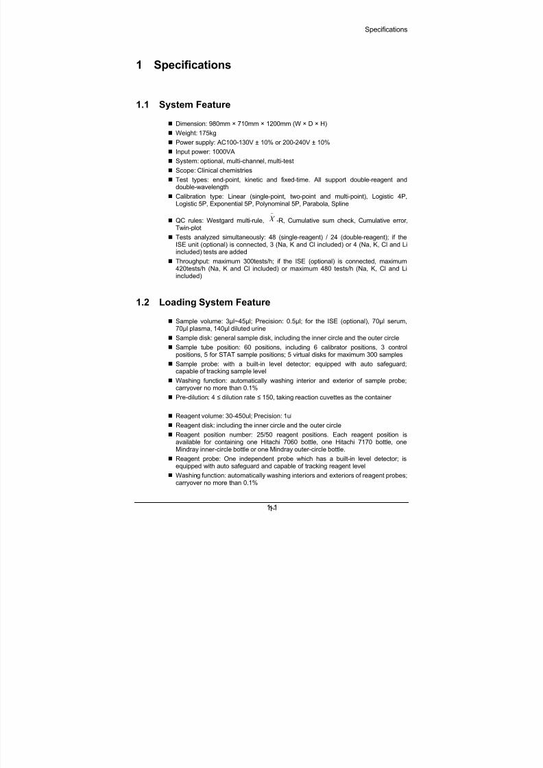
Dimension: 980mm × 710mm × 1200mm (W × D × H)
Weight: 175kg
Power supply: AC100-130V ± 10% or 200-240V ± 10%
Input power: 1000VA
System: optional, multi-channel, multi-test
Scope: Clinical chemistries
Test types: end-point, kinetic and fixed-time. All support double-reagent and
double-wavelength Calibration type: Linear (single-point, two-point and multi-point), Logistic 4P,
Logistic 5P, Exponential 5P, Polynominal 5P, Parabola, Spline
QC rules: Westgard multi-rule,
−
X -R, Cumulative sum check, Cumulative error,Twin-plot
Tests analyzed simultaneously: 48 (single-reagent) / 24 (double-reagent); if theISE unit (optional) is connected, 3 (Na, K and Cl included) or 4 (Na, K, Cl and Liincluded) tests are added
Throughput: maximum 300tests/h; if the ISE (optional) is connected, maximum420tests/h (Na, K and Cl included) or maximum 480 tests/h (Na, K, Cl and Liincluded)
1.2 Loading System Feature
Sample volume: 3µl~45µl; Precision: 0.5µl; for the ISE (optional), 70µl serum,70µl plasma, 140µl diluted urine
Sample disk: general sample disk, including the inner circle and the outer circle
Sample tube position: 60 positions, including 6 calibrator positions, 3 controlpositions, 5 for STAT sample positions; 5 virtual disks for maximum 300 samples
Sample probe: with a built-in level detector; equipped with auto safeguard;capable of tracking sample level
Washing function: automatically washing interior and exterior of sample probe;carryover no more than 0.1%
Pre-dilution: 4 ≤ dilution rate ≤ 150, taking reaction cuvettes as the container
Reagent volume: 30-450ul; Precision: 1ul
Reagent disk: including the inner circle and the outer circle
Reagent position number: 25/50 reagent positions. Each reagent position isavailable for containing one Hitachi 7060 bottle, one Hitachi 7170 bottle, oneMindray inner-circle bottle or one Mindray outer-circle bottle.
Reagent probe: One independent probe which has a built-in level detector; isequipped with auto safeguard and capable of tracking reagent level
Washing function: automatically washing interiors and exteriors of reagent probes;carryover no more than 0.1%
8/20/2019 Mindray BS 300 Analizor Service Manual
http://slidepdf.com/reader/full/mindray-bs-300-analizor-service-manual 10/119
Specifications
1-2
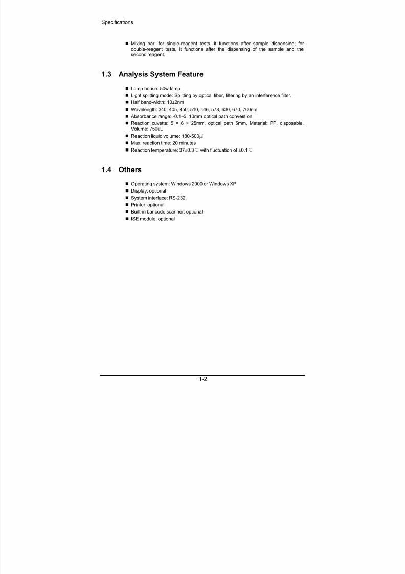
Mixing bar: for single-reagent tests, it functions after sample dispensing; fordouble-reagent tests, it functions after the dispensing of the sample and thesecond reagent.
1.3 Analysis System Feature
Lamp house: 50w lamp
Light splitting mode: Splitting by optical fiber, filtering by an interference filter.
Half band-width: 10±2nm
Wavelength: 340, 405, 450, 510, 546, 578, 630, 670, 700nm
Absorbance range: -0.1~5, 10mm optical path conversion
Reaction cuvette: 5 × 6 × 25mm, optical path 5mm. Material: PP, disposable.Volume: 750uL
Reaction liquid volume: 180-500µl
Max. reaction time: 20 minutes
Reaction temperature: 37±0.3 with fluctuation of ±0.1
1.4 Others
Operating system: Windows 2000 or Windows XP
Display: optional
System interface: RS-232
Printer: optional
Built-in bar code scanner: optional ISE module: optional
8/20/2019 Mindray BS 300 Analizor Service Manual
http://slidepdf.com/reader/full/mindray-bs-300-analizor-service-manual 11/119
System Installation
2-1
2 System Installation
NOTE:The analyzer should be installed or moved to another place byMindray-authorized personnel only.
2.1 Check before Installation
The user should provide the environment that meets the requirements mentioned inthe Operation Manual. Check if the environment meets the requirements beforeinstalling the analyzer. Refer to the chapter 2 of the Operation Manual for details.
2.2 Installation Procedure
1 Ensure available installation fields and environments in hospitals.
2 Confirm the reagents and calibrators.
3 Go to the installation field, and then check the delivery list for acceptance.
4 Install the four handles on the four angles of the analyzer. Move the analyzerto the installation field, fix the casters, and then remove the handles.
5 Insta ll the computer, display and printer.6 Open the front plate, and check whether cable connections are loose. Open
the top plate, check whether the probe assemblies, reagent disk and sampledisk are intact and in good performance.
7 Connect the communication cable, power cable, grounding wire, waste tankand deionized water tank. Install the used-cuvette bucket, reagent probe,sample probe and mixing bar.
8 Top up the deionized water tank with deionized water.
9 Put reaction cuvettes in the feeder. Remember to check whether the surfacesof the cuvettes are smooth. In case of any bump, remove it before loading thecuvette to the compartment. Do not touch the light transmission part of thecuvette in which the colorimetric reading is taken.
10 Load acid and alkaline detergents to positions 46 and 47, and distilled waterto positions 49 on the reagent disk. Load distilled water to position 60 on thesample disk.
11 Switch on the analyzer as follows: POWER → ANALYZING UNIT POWER→display→ computer → printer.
12 After Windows is started, double-click the icon of BS-300 on the desktop tostart the system software. The system program will automatically finish theself-test, become online and warm up the reaction cuvettes within about 30minutes.
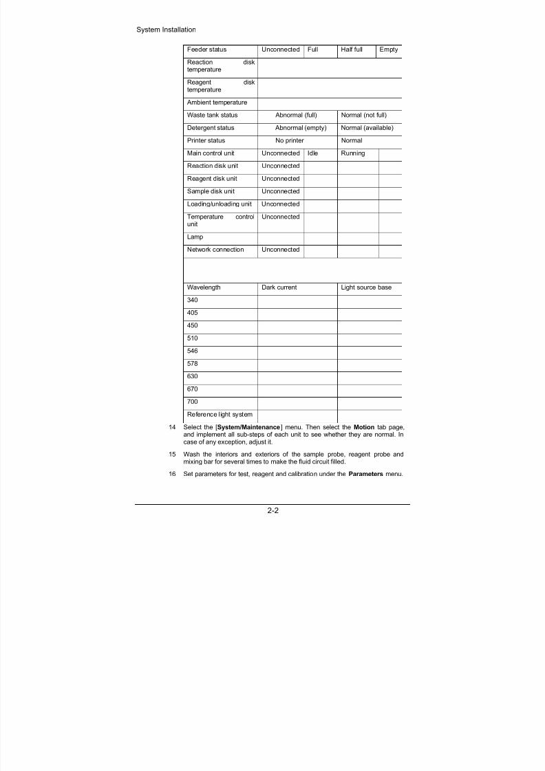
13 Select the [System/Status] menu, and then observe the system status andrecord it in the table below:
8/20/2019 Mindray BS 300 Analizor Service Manual
http://slidepdf.com/reader/full/mindray-bs-300-analizor-service-manual 12/119
System Installation
2-2
Feeder status Unconnected Full Half full Empty
Reaction disktemperature
Reagent disktemperature
Ambient temperature
Waste tank status Abnormal (full) Normal (not full)
Detergent status Abnormal (empty) Normal (available)
Printer status No printer Normal
Main control unit Unconnected Idle Running
Reaction disk unit Unconnected
Reagent disk unit Unconnected
Sample disk unit Unconnected
Loading/unloading unit Unconnected
Temperature controlunit
Unconnected
Lamp
Network connection Unconnected
Wavelength Dark current Light source base
340
405
450
510
546
578
630
670
700
Reference light system
14 Select the [System/Maintenance] menu. Then select the Motion tab page,and implement all sub-steps of each unit to see whether they are normal. Incase of any exception, adjust it.
15 Wash the interiors and exteriors of the sample probe, reagent probe andmixing bar for several times to make the fluid circuit filled.
16 Set parameters for test, reagent and calibration under the Parameters menu.

8/20/2019 Mindray BS 300 Analizor Service Manual
http://slidepdf.com/reader/full/mindray-bs-300-analizor-service-manual 13/119
System Installation
2-3
17 Request for calibration and samples, run and then debug the results.
18 After debugging the results, fill them in the table below:
Test ALT CREA BUN
Target value
2sd range
Test value 1
Test value 2
Test value 3
Test value 4
Test value 5
Test value 6
Test value 7
Test value 8
Test value 9
Test value 10
19 Training
Can the user complete daily tests? Yes No
Is the user familiar with the analytical methods such askinetic, two-point, endpoint?
Yes No
Is the user familiar with the daily, weekly and monthlymaintenance and relevant maintenance methods? Yes No
Is the user skilled in washing dust screens? Yes No
Is the user skilled in cleaning and replacing the probesand the mixing bar?
Yes No
Is the user skilled in replacing the plunger assembliesof syringes?
Yes No
Is the user skilled in replacing the lamp? Yes No
Is the user skilled in maintenance of built-in bar codescanner?
Yes No
Is the user skilled in maintenance of ISE unit? Yes No
Does the user know the positions, roles andpreparation methods of distilled water and acid andalkaline detergents?
Yes No

8/20/2019 Mindray BS 300 Analizor Service Manual
http://slidepdf.com/reader/full/mindray-bs-300-analizor-service-manual 14/119

8/20/2019 Mindray BS 300 Analizor Service Manual
http://slidepdf.com/reader/full/mindray-bs-300-analizor-service-manual 15/119
System Descriptions
3-1
3 System Descriptions
The BS-300 analyzer consists of the analyzing unit, operation unit and output unit.
The analyzing unit consists of the dispensing system, feeder, temperature controlsystem, photometric system and fluid system.
3.1 Dispensing System
The dispensing system consists of the probe assemblies (including the reagentprobe assembly, sample probe assembly and mixing bar assembly), reagent disk,sample disk and reaction disk.
3.1.1 Probe assemblies
Among the probe assemblies, the mixing bar assembly is the same as the reagentprobe assembly and the sample probe assembly, except that the knurled axis is30cm shorter.
Every probe assembly has a horizontal photoelectric switch and a verticalphotoelectric switch. These switches are used for defining horizontal and vertical

8/20/2019 Mindray BS 300 Analizor Service Manual
http://slidepdf.com/reader/full/mindray-bs-300-analizor-service-manual 16/119
System Descriptions
3-2
initial positions of probe assemblies. The horizontal and vertical step motorsprecisely control the horizontal and vertical movements of the probe assemblies, andthe synchronizing belts serve as the gearing.
The shaft and the bushing must corporate with each other precisely, so they cannotbe used confusedly.
3.1.2 Disk assemblies
The three disk assemblies are different in their coders. The coder corresponds to theposition where disks should stop. There is an initial-position mark under every coder.The three coders of the three disks have three coder transducers. Each transducerhas two photoelectric switches for inducing the rotation and initial position of thedisk.
The step motors control the disk assemblies, and the synchronizing belts serve asthe gearing.

8/20/2019 Mindray BS 300 Analizor Service Manual
http://slidepdf.com/reader/full/mindray-bs-300-analizor-service-manual 17/119
System Descriptions
3-3
There is a build-in bar code scanner to the left of the sample disk. The scanner isoptional.
Sample probe assemblyBuild-in bar code scanner
3.2 Feeder
The feeder consists of the feeder assemblies and the manipulator. It is designated tosend cuvette segments to the reaction disk, take out the used ones and abandonthem to the used-cuvette bucket.
3.2.1 Feeder assemblies
The feeder assemblies include the gearing assembly, cuvette compartmentassembly, cuvette-pushing assembly and no-cuvette detection assembly (see thefollowing figure).
The supporting plate of the feeder assemblies is a square piece of steel that isconnected to the analyzing unit by its four poles, which are secured by four nuts. Unscrewing the nuts, you can disassemble the feeder assemblies from the analyzingunit easily.

8/20/2019 Mindray BS 300 Analizor Service Manual
http://slidepdf.com/reader/full/mindray-bs-300-analizor-service-manual 18/119
System Descriptions
3-4
There are five transducers that are shown in the figure below.
The no-cuvette transducer is used to detect whether there is a cuvette segment atthe loading position. The insufficient-cuvette transducer is used for determinewhether there are less than 10 reaction cuvettes in the compartment or not. If yes,the analyzer will give a prompt.
Pressure Transducer
No-Cuvette
Transducer
Cuvette-Pushing
Limit Transducer Insufficient-Cuvette
Transducer
Cuvette-taking limit
transducer
3.2.2 Manipulator
Two step motors (horizontal and vertical) supply power for horizontal and verticalmovements of the manipulator.
The upper finger and lower finger are same in their structures. They work together toreplace used cuvette segments with new ones.
The manipulator runs in a relatively complicated way. There are four transducers onit: vertical transducer, horizontal transducer and two finger transducers.
8/20/2019 Mindray BS 300 Analizor Service Manual
http://slidepdf.com/reader/full/mindray-bs-300-analizor-service-manual 19/119
System Descriptions
3-5
3.3 Temperature Control System
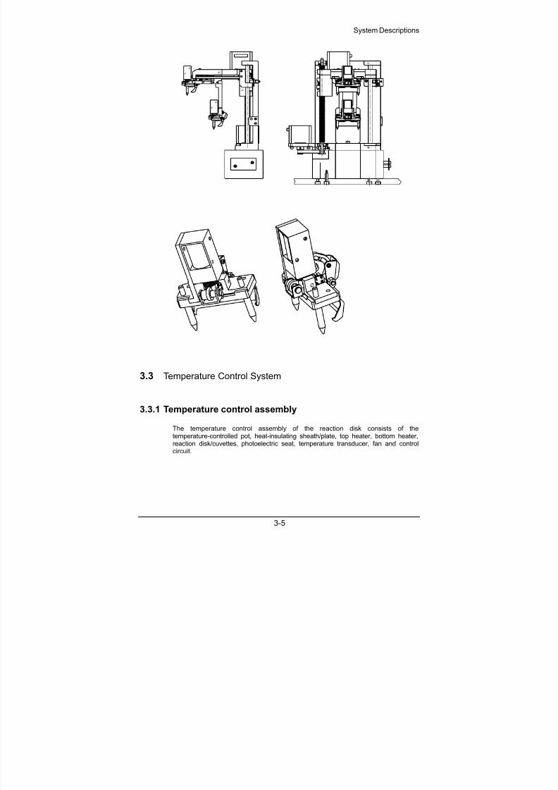
3.3.1 Temperature control assembly
The temperature control assembly of the reaction disk consists of thetemperature-controlled pot, heat-insulating sheath/plate, top heater, bottom heater,reaction disk/cuvettes, photoelectric seat, temperature transducer, fan and controlcircuit.

8/20/2019 Mindray BS 300 Analizor Service Manual
http://slidepdf.com/reader/full/mindray-bs-300-analizor-service-manual 20/119
System Descriptions
3-6
1: Temperature transducer and the support
2: Fan
3: photoelectric seat
4: Heat-insulating sheath5: top heater
6: Cover
7: temperature-controlled pot
8: bottom heater
Upper heater: square in shape, 220/110VAC, 125W
Lower heater: ring in shape, 220/110VAC, 350W
Total power: 475W.
The function of heaters is to compensate the heat for incubating the reagent and formaintaining the temperature of the temperature-controlled chamber.
Fans are used in series in the temperature-controlled chamber. It makes the aircirculating in the chamber, and enhances the convective heat exchange. There arefour fans in the chamber. All have the alarm function.
The temperature transducer feeds back the air temperature at the position severalmillimeters from the bottom of the reaction cuvette.
The overheat protection switch is to switch off the power when the temperature
controller does work and the temperature-controlled chamber reaches 55, so as toavoid overheat or fire. When the temperature-controlled chamber becomes 35,
this switch will automatically be reset.
3.3.2 Reagent preheating
The preheating assembly consists of two aluminum plates, a Teflon tube having nineloop sections, heating components, transducer, temperature protection switch,thermal conductive colloid, a section of tube and the reagent probe.
The temperature of the thermal source of the preheater is controlled at 45. Theinitial temperature of the reagent is 4 ~ 10 when it is taken out of the refrigeration

8/20/2019 Mindray BS 300 Analizor Service Manual
http://slidepdf.com/reader/full/mindray-bs-300-analizor-service-manual 21/119
System Descriptions
3-7
chamber. When the reagent passes the heater, its temperature increases to 35.
Then the reagent is added into the reaction cuvette and the preheating process isfinished.
Reagent preheating assembly
3.3.3 Reagent refrigeration
The refrigeration module consists of refrigeration cabin, PU heat-insulating sheath,reagent disk, reagent bottle, temperature transducer, refrigeration flakes, heatsinking component, fan and control circuit. The refrigeration module is shown in thefollowing figure.
The refrigeration assembly consists of fan, hot-end radiator, POM connector,cold-end heat-conductive aluminum block, and PELTIER refrigeration flake. Eachanalyzer has two such refrigeration assemblies, as shown in the figure below. Thecold-side of the refrigeration flake clings to the refrigeration compartment, and thehot-side clings to the radiator (The side having letters should cling to the refrigerationaluminum block).

8/20/2019 Mindray BS 300 Analizor Service Manual
http://slidepdf.com/reader/full/mindray-bs-300-analizor-service-manual 22/119
System Descriptions
3-8
Each refrigeration flake corresponds to a heat-sinking block and a cooling fan. Itshould be installed with the cold side upward.
3.4 Photometric System
The photometric system consists of a measurement photometric system and areference photometric system. The measurement photometric system provides 9monochromatic lights to measure the absorbance of the reacting liquid in the rotatingreaction cuvettes. The reference photometric system compensates themeasurement photometric system to make the measurement more accurate.
共 路
传光束小端
卤 钨灯 聚 光镜 传 光 束 小透 镜 反应 杯 滤 光 片 小 透 镜 光 电 管
光 电管
参考光路
测 量 光 路
Tungsten-halogen
lamp Biconvex lens Main fiber
Fibers
Plano
convex lens Cuvette Filter Plano
convex lens Photodiode
Reference light
Photodiode
.
.
.
Measurement
lights
3.5 Fluid SystemThe fluid system is shown in the following figure.

8/20/2019 Mindray BS 300 Analizor Service Manual
http://slidepdf.com/reader/full/mindray-bs-300-analizor-service-manual 23/119
System Descriptions
3-9
Reagent syringe
Sample syringe
Mixing bar
As shown in the figure above, the fluid system consists of interior washing andexterior washing.
The syringe assembly controls the aspiration volume by controlling the travel of thesample/reagent syringe. It is the core part of the fluid system.

8/20/2019 Mindray BS 300 Analizor Service Manual
http://slidepdf.com/reader/full/mindray-bs-300-analizor-service-manual 24/119
System Descriptions
3-10
3.6 ISE Module (optional)
The ISE module that is used to measure the concentration of K+, Na
+, Cl
- and Li
+ in
serum, plasma and urine consists of ion-selective electrodes, peristaltic pumps andcalibrants.
Waste
ISEPump W Pump BPump A
Calibrant B Calibrant A

8/20/2019 Mindray BS 300 Analizor Service Manual
http://slidepdf.com/reader/full/mindray-bs-300-analizor-service-manual 25/119
System Descriptions
3-11

8/20/2019 Mindray BS 300 Analizor Service Manual
http://slidepdf.com/reader/full/mindray-bs-300-analizor-service-manual 26/119
8/20/2019 Mindray BS 300 Analizor Service Manual
http://slidepdf.com/reader/full/mindray-bs-300-analizor-service-manual 27/119
Functions of Boards
4-1
4 Functions of Boards
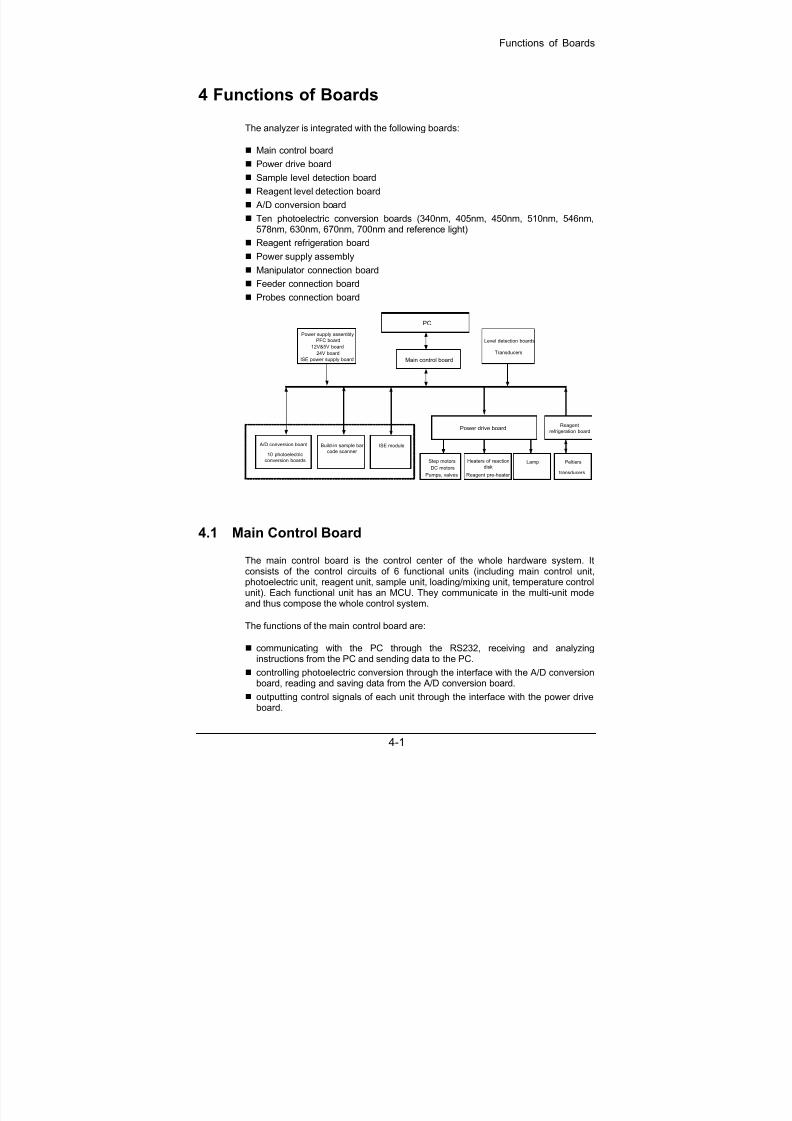
The analyzer is integrated with the following boards:
Main control board
Power drive board
Sample level detection board
Reagent level detection board
A/D conversion board
Ten photoelectric conversion boards (340nm, 405nm, 450nm, 510nm, 546nm,578nm, 630nm, 670nm, 700nm and reference light)
Reagent refrigeration board
Power supply assembly
Manipulator connection board
Feeder connection board
Probes connection board
Main control board
Power drive board
Power supply assembly
PFC board
Heaters of reaction
disk
Reagent pre-heater
PC
Level detection boards
A/D conversion board Build-in sample bar
code scanner ISE module
Step motors
DC motors
Lamp
Reagent
refrigeration board
Peltiers
transducers
Transducers12V&5V board
24V board
10 photoelectric
conversion boards
Pumps, valves
ISE power supply board
4.1 Main Control Board
The main control board is the control center of the whole hardware system. Itconsists of the control circuits of 6 functional units (including main control unit,photoelectric unit, reagent unit, sample unit, loading/mixing unit, temperature controlunit). Each functional unit has an MCU. They communicate in the multi-unit modeand thus compose the whole control system.
The functions of the main control board are:
communicating with the PC through the RS232, receiving and analyzinginstructions from the PC and sending data to the PC.
controlling photoelectric conversion through the interface with the A/D conversionboard, reading and saving data from the A/D conversion board.
outputting control signals of each unit through the interface with the power driveboard.

8/20/2019 Mindray BS 300 Analizor Service Manual
http://slidepdf.com/reader/full/mindray-bs-300-analizor-service-manual 28/119
Functions of Boards
4-2
receiving signals of fluid level detection and bump collision through the interfacewith the level detection boards.
detecting signals from temperature transducers and controlling temperature of thereaction disk and reagent preheating.
receiving signals from position transducers, deionized water transducer and wastetransducer and controlling the transducers.
controlling the built-in sample bar code scanner, reading the data and sending it tothe PC.
controlling the ISE module, reading the results and sending them to the PC.
4.2 Power Drive Board
The main functions of the power drive board are to receive the control signals fromthe main control board and control drive components. The block diagram of thepower drive board is shown in the figure below.
Control signals from
Main Control Board
to 13 step motors to 2 DC motors
to 2 solenoid valves to 3 pumps
to 2 heaters of
reaction diskto lamp power
to reagent
preheating
to 2 magnets
4.3 A/D Conversion Board
The 10 photoelectric conversion circuits convert the intensity signals of the lightstransmitting through the reaction cuvettes to electric signals, and then transmit themto the A/D conversion board through a 5-core shielded cable. Photoelectricconversion boards for different wavelengths have different gains and cannot bereplaced by each other.
The A/D conversion board filters and amplifies the 10 channels of electric signalsoutput from the photoelectric conversion boards, transmits them through themulti-way gating switch to the A/D converter and then sends them to the main controlboard for further processing.
4.4 Reagent Refrigeration Board
The circuits of the reagent refrigeration board include the refrigeration circuit and thefan circuit.
The refrigeration circuit is needed to work continuously, so it is powered separately.
The control objects of the reagent refrigeration board include:
Reagent refrigeration: 2 PELTIER components, 4 fans.

8/20/2019 Mindray BS 300 Analizor Service Manual
http://slidepdf.com/reader/full/mindray-bs-300-analizor-service-manual 29/119
Functions of Boards
4-3
Heat sink system for the whole device: 3 lamp-cooling fans, 4 temperature controlfans of the reaction disk.
4.5 Level Detection Boards
The level detection boards that include sample level detection board and reagentlevel detection board are used to detect the fluid level of sample and reagentseparately. When the analyzer aspirates reagents/samples, the probes dip into theliquid to a specific depth, so as to avoid carryovers that have impacts on test results,and to avoid air aspiration when the reagent/sample is insufficient.
4.6 Feeder Connection Board
The feeder connection board transfers the signals between the feeder transducerand the main control board, and connects the power drive board and the loadingmotor (DC).
Connections:
Connector Connected with
J91 Front transducer
J92 Back transducer
J93 Intermediate transducer
J94 No-cuvette transducerJ95 Pressure transducer
J96 Motor control wire (connected with the power drive board)
J97 Motor control wire (connected the motors)
J98 Cuvette-loading button
J99 Connection wire of the main control board
4.7 Manipulator Connection Board
The manipulator connection board transfers the signals between the manipulatortransducer and the main control board, and connects the power drive board and theelectromagnet.
Connections:
Connector Connected with
J101 Horizontal loading position transducer
J102 Vertical loading position transducer
J103 Electromagnet-closing transducer of the lower hand

8/20/2019 Mindray BS 300 Analizor Service Manual
http://slidepdf.com/reader/full/mindray-bs-300-analizor-service-manual 30/119
Functions of Boards
4-4
Connector Connected with
J108 Electromagnet-closing transducer of the upper hand
J104 Drive wire of the electromagnet of the upper hand
J105 Drive wire of the electromagnet of the lower hand
J106 Drive wire of the electromagnet (connected with the power driveboard)
J107 Connection wire of the main control board
J109 Safeguard transducer (reserved)
J110 Safeguard transducer (reserved)
4.8 Probes Connection Board
The probes connection board transfers the signals between the sample/reagent leveldetection board and the main control board, inputs the temperature signals, outputsthe reagent preheating signals, and transfers the signals between the power driveboard and the mixing motor (DC).
Connector Connected with
J200 Interface of the sample level detection board
J201 Interface of the reagent level detection board
J202 Interface of the mixing motor (DC)
J203 Sample detection signal interface of the main control board
J204 Reagent detection signal interface of the main control board
J205 Temperature control signal interface of the reaction disk
J206 Reagent preheating signal interface
J207 Interface of the power drive board
4.9 Power Supply Assembly
The power supply assembly consists of three boards: PFC board, 24V board,12V&5V board and ISE (optional) power supply board.
The functions of the PFC board include:
AC/DC conversion;
Supplying the +390V and VDD voltage to the 24V board and the 12V&5V board;
Supplying stable 12V voltage for the lamp;
Supplying control signals of the analyzing unit switch to control the C12V, 5V and24V outputs.
The 24V board converts the 390VDC current transmitted from the PFC board to theseparated 24VDC outputs through the forward converter.

8/20/2019 Mindray BS 300 Analizor Service Manual
http://slidepdf.com/reader/full/mindray-bs-300-analizor-service-manual 31/119
Functions of Boards
4-5
The 12V&5V board converts the 390VDC voltage from the PFC board to B12V,C12V and 5V voltages through the forward converter.
The ISE power supply board converts the 12V of the reagent refrigeration board to24V that provides power supply for the ISE unit (optional).

8/20/2019 Mindray BS 300 Analizor Service Manual
http://slidepdf.com/reader/full/mindray-bs-300-analizor-service-manual 32/119
8/20/2019 Mindray BS 300 Analizor Service Manual
http://slidepdf.com/reader/full/mindray-bs-300-analizor-service-manual 33/119
Maintenance and Service
5-1
5 Maintenance and Service
WARNING:
Before disassembling or assembling the analyzing unit, ensure thePOWER is placed to OFF.
The probe tip is sharp and can cause puncture wounds. To preventinjury, exercise caution when working around the probe.
BIOHAZARD:
Wear gloves and lab coat and, if necessary, goggles.
Dispose of the waste in accordance with your local or nationalguidelines for biohazard waste disposal.
CAUTION:Please use Mindray-recommended consumables. Other consumablesmay decrease the system performance.
Refer to the BS-300 Chemistry Analyzer Operation Manual for details about
unclogging the sample probe
unclogging the reagent probe
replacing the sample probe
replacing the reagent probe
replacing the mixing bar
replacing the plunger assembly of syringe
replacing the lamp
5.1 Replacing Light Filter Assembly
The light filter and optical assembly are fixed in the supporting sleeve. The back endis compacted and enclosed with the photoelectric amplification board and the screengland. Generally, the supporting sleeve is replaced together with the filter and opticalassembly.

8/20/2019 Mindray BS 300 Analizor Service Manual
http://slidepdf.com/reader/full/mindray-bs-300-analizor-service-manual 34/119
Maintenance and Service
5-2
Figure 5-1 Light filter assembly
Supporting Sleeve
GasketFilter
Flat Spring
Lens
GasketLens Seat
Photoelectric
Conversion Board
Screw Shield Box
WARNING:
Before operating, ensure to place the POWER (main switch) to OFF.
1 Unscrew (counter clockwise) the two cap screws on the screen glandwhose wavelength is to be replaced.
2 Open the cover of the A/D conversion board, and unplug the plugcorresponding to certain wavelength.
8/20/2019 Mindray BS 300 Analizor Service Manual
http://slidepdf.com/reader/full/mindray-bs-300-analizor-service-manual 35/119
Maintenance and Service
5-3
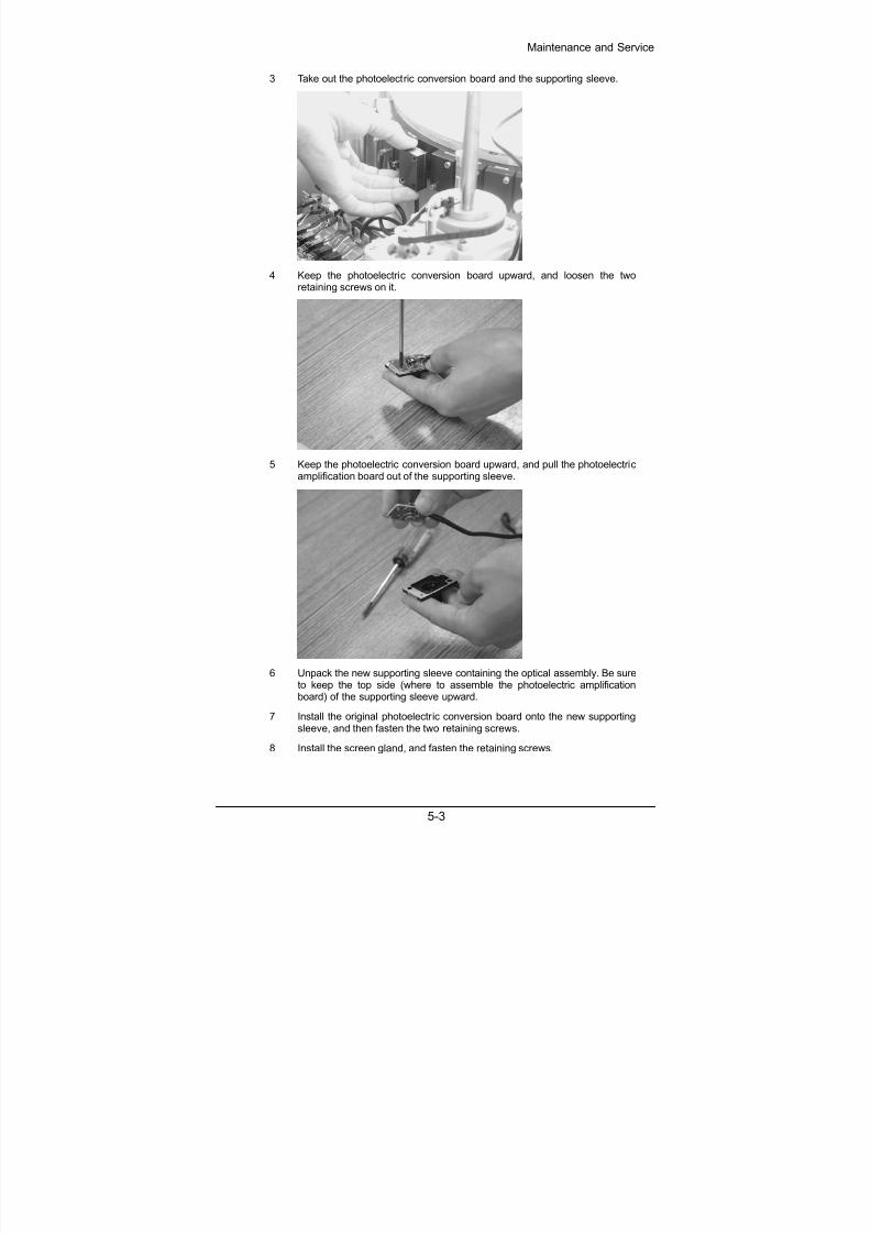
3 Take out the photoelectric conversion board and the supporting sleeve.
4 Keep the photoelectric conversion board upward, and loosen the tworetaining screws on it.
5 Keep the photoelectric conversion board upward, and pull the photoelectricamplification board out of the supporting sleeve.
6 Unpack the new supporting sleeve containing the optical assembly. Be sureto keep the top side (where to assemble the photoelectric amplificationboard) of the supporting sleeve upward.
7 Install the original photoelectric conversion board onto the new supportingsleeve, and then fasten the two retaining screws.
8 Install the screen gland, and fasten the retaining screws.

8/20/2019 Mindray BS 300 Analizor Service Manual
http://slidepdf.com/reader/full/mindray-bs-300-analizor-service-manual 36/119
Maintenance and Service
5-4
9 Connect the photoelectric conversion board to the A/D conversion board,and assemble the cover.
WARNING:
When replacing the light filter assembly, do not touch the opticalassembly in the supporting sleeve and the photoelectric receiving tubeof the photoelectric conversion board by hand.
The light filters and the photoelectric conversion boards are inone-to-one relationship. Do not disarrange them.
5.2 Replacing Optical Fiber
WARNING:
Before operating, ensure to place the POWER (main switch) to OFF.
1 Unscrew the four screws on the supporting pillars of the cuvette feeder, andremove the cuvette feeder.
8/20/2019 Mindray BS 300 Analizor Service Manual
http://slidepdf.com/reader/full/mindray-bs-300-analizor-service-manual 37/119
Maintenance and Service
5-5
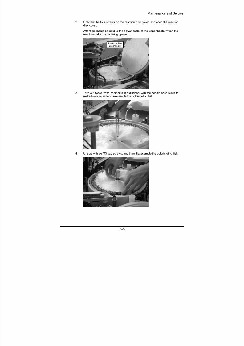
2 Unscrew the four screws on the reaction disk cover, and open the reactiondisk cover.
Attention should be paid to the power cable of the upper heater when thereaction disk cover is being opened.
Power cable ofupper heater
3 Take out two cuvette segments in a diagonal with the needle-nose pliers tomake two spaces for disassemble the colorimetric disk.
4 Unscrew three M3 cap screws, and then disassemble the colorimetric disk.

8/20/2019 Mindray BS 300 Analizor Service Manual
http://slidepdf.com/reader/full/mindray-bs-300-analizor-service-manual 38/119
Maintenance and Service
5-6
5 Use an M3 cap screwdriver to loosen the retaining screws of the opticalfibers on the colorimetric clamp and the reference light support.
6 Take out the optical fibers one by one, and fix the optical components in the
colorimetric clamp by fastening the screws slightly.
Screw of the reference light
7 Draw out all the nine optical fibers from the reaction compartment.
8 Loosen the M3 cap screw (used for retaining optical fibers) on the lamphousing, and then draw out the optical fibers.
9 Put nine of the ten branches of the new optical fiber into the reaction diskfrom its bottom one by one, loosen the retaining screw, insert the opticalfiber to the end, and then fasten the retaining screw.
10 Fix the reference light optical fiber.

8/20/2019 Mindray BS 300 Analizor Service Manual
http://slidepdf.com/reader/full/mindray-bs-300-analizor-service-manual 39/119
Maintenance and Service
5-7
11 Fix the optical fiber of the lamp housing.
12 Put the colorimetric disk back and fix it.
13 Put the reaction disk cover back and fix it.
14 Install the cuvette feeder and fix it.
CAUTION:
When replacing the optical fiber, ensure that its bending radius is noless than 20cm. Otherwise, the optical fiber will be damaged.
5.3 Adjusting Reaction Disk, Manipulator and Feeder
NOTE:Debug the lower arm first (The relation between the lower arm positionand the reaction cuvette position is very important.), and then the upperarm. When debugging the lower arm, move the cuvette compartmentaside.
1 Disassemble the cuvette feeder, and adjust the circular position of thereaction disk (through the initial position transducer of the reaction disk) tothe standard position (The finger of the lower arm points to the center of theslot between reaction cuvette segments).
2 Horizontally adjust the manipulator to the standard position (The finger ofthe lower arm can work on reaction cuvettes well, and it should be 0.2mmaway from the nearest point of the reaction cuvette).

8/20/2019 Mindray BS 300 Analizor Service Manual
http://slidepdf.com/reader/full/mindray-bs-300-analizor-service-manual 40/119
Maintenance and Service
5-8
3 Vertically adjust the manipulator the standard position (The finger of thelower arm can work on reaction cuvette well, and the finger support of thelower arm should be 0.15mm above the reaction cuvette.).
4 Run the manipulator to the position for taking new cuvettes, andhorizontally adjust the reaction cuvettes in the feeder. When catching acuvette, ensure a clearance of 0.4mm ~ 0.6mm between the finger of theupper arm and the cuvette, and center them.
5.4 Adjusting Probes and Disks
NOTE:
Adjust the positions of the three probes and reaction cuvettes, and thenothers.
Adjust the working position of the reagent probe (To minimize thecumulative error, ensure that the reagent probe return to the initial positionbefore each adjustment.) as follows:
A For the reagent discharging position, ensure the reagent probe is inthe center of the reaction cuvette and the probe tin is 2 ~ 3mm awayfrom the bottom of the reaction cuvette.
B Adjust the position of the initial-position transducer of the reagentdisk. Ensure the mouths of reagent cuvettes in the inner and outercircles fit the reagent disk cover well.
C Adjust the washing position of the reagent probe. Ensure the reagentprobe is in the center of the wash well and the probe pin is 5mmaway from the bottom of the wash well. If necessary, adjust theposition of the wash well.
1
D Adjust the reagent probe’s position on the outer circle of the reagentdisk. Ensure the reagent probe is in the center of the hole of the outer
circle.
8/20/2019 Mindray BS 300 Analizor Service Manual
http://slidepdf.com/reader/full/mindray-bs-300-analizor-service-manual 41/119
Maintenance and Service
5-9
E Adjust the reagent probe’s position on the inner circle of the reagentdisk. Ensure the reagent probe is in the center of the hole of the innercircle.
Adjust the working position of the sample probe (To minimize thecumulative error, ensure that the sample probe return to the initial positionbefore each adjustment.) as follows:
A For the sample discharging position, ensure the sample probe is inthe center of the reaction cuvette and the probe tin is 2 ~ 3mm awayfrom the bottom of the reaction cuvette.
B Adjust the position of the initial-position transducer of the sampledisk. Ensure the mouths of sample cuvettes in the inner and outercircles fit the reagent disk cover well.
C Adjust the washing position of the sample probe. Ensure the sampleprobe is in the center of the wash well and the probe pin is 5mmaway from the bottom of the wash well. If necessary, adjust theposition of the wash well.
D Adjust the sample probe’s position on the outer circle of the sampledisk. Ensure the sample probe is in the center of the hole of the outercircle.
2
E Adjust the sample probe’s position on the inner circle of the sampledisk. Ensure the sample probe is in the center of the hole of the innercircle.
Adjust the working position of the mixing bar.
A Switch off the analyzing unit first, and then rotate the mixing arm tosee if its rotation radius is proper. If the mixing bar cannot reach thecenter of the reaction cuvette, adjust the position of the mixing bar onthe mixing arm properly.
B Disassemble the mixing arm, and then switch on the analyzing unit torun the reaction disk and stop it at any cuvette. Hold the mixing armby hand, and fix it at the center of the reaction cuvette.
C Vertically adjust the mixing bar’s position in the reaction cuvette.Ensure the mixing bar tip is 1 ~ 2mm away from the bottom of thereaction cuvette.
3
D Adjust the washing position of the mixing bar. Ensure the mixing baris in the center of the wash well and about 5mm away from thebottom of the wash well. If necessary, adjust the position of the washwell.
4 In the engineering adjustment software, select the Debug instruction menu, and rotate the reaction disk for one lap. Dive probes and mix thereactant at every position or every several positions to see if the threeprobes interfere with any reaction cuvette (Command 61). If the mixing barknocks the side or the bottom of any cuvette, repeat Step 3.
8/20/2019 Mindray BS 300 Analizor Service Manual
http://slidepdf.com/reader/full/mindray-bs-300-analizor-service-manual 42/119
Maintenance and Service
5-10
5.5 Replacing Components of ISE Unit (optional)
5.5.1 Replacing Tubing
NOTE:
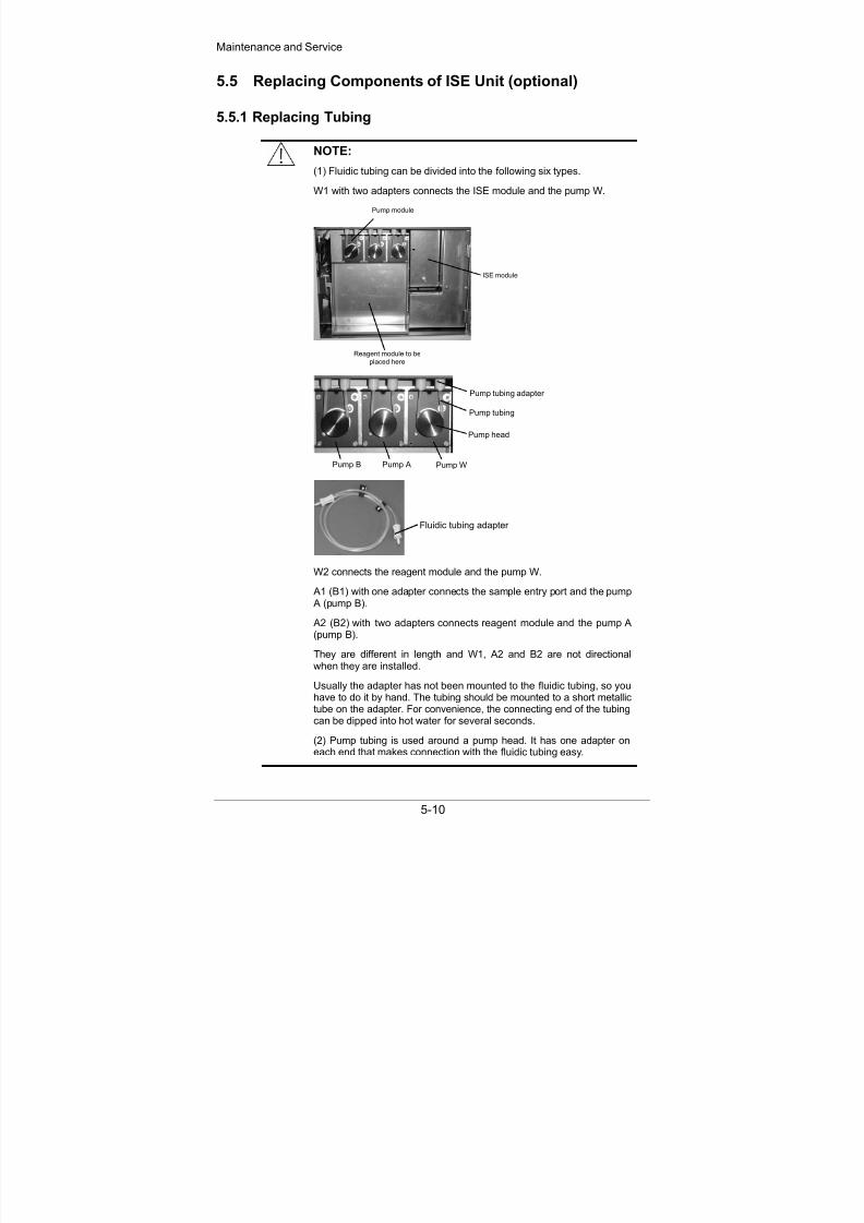
(1) Fluidic tubing can be divided into the following six types.
W1 with two adapters connects the ISE module and the pump W.
Pump module
ISE module
Reagent module to be
placed here
Pump tubing
Pump tubing adapter
Pump B Pump A Pump W
Pump head
Fluidic tubing adapter
W2 connects the reagent module and the pump W.
A1 (B1) with one adapter connects the sample entry port and the pump
A (pump B).
A2 (B2) with two adapters connects reagent module and the pump A(pump B).
They are different in length and W1, A2 and B2 are not directionalwhen they are installed.
Usually the adapter has not been mounted to the fluidic tubing, so youhave to do it by hand. The tubing should be mounted to a short metallictube on the adapter. For convenience, the connecting end of the tubingcan be dipped into hot water for several seconds.
(2) Pump tubing is used around a pump head. It has one adapter on
each end that makes connection with the fluidic tubing easy.

8/20/2019 Mindray BS 300 Analizor Service Manual
http://slidepdf.com/reader/full/mindray-bs-300-analizor-service-manual 43/119
Maintenance and Service
5-11
5.5.1.1 Replacing Fluidic Tubing W1 and W2
1 Place the POWER to OFF.
2 Open the ISE unit door.
3 If you want to replace the W1, unscrew the screw of the ISE module andtake off the cover.
4 Put out the fluidic tubing W2 and insert it into a container such as a cup thatis used to contain the waste solution flowing from the W2.
5 Start the analyzing unit and the system software.
6 Enter the ISE Maintenance screen of the system software.
7 Click the Maintenance button several times until there is no solutionflowing out from the W2.
8 Place the POWER to OFF.
9 If you want to replace W1, pull out its two adapters directly from the wastepump tubing adapter and the right angle adapter that is fixed to thecompression plate.
Right angle adapter
The side matches
the adapter of
fluid tubing W1
The side with a recessmatches the compression
plate of the ISE module.
Note that when pulling out the fluidic tubing adapter, in order not to releasethe right angle adapter, you can hold the right angle adapter with a finger.
After that, install a new W1. For W2 exchange, it just needs to replace theW2 with a new one.
10 If you want to replace the W2, replace it with a new one. Otherwise, insertthe W2 back to the reagent module.
11 Place the POWER to ON.
12 Enter the System Maintenance screen of the system software.
13 Select the Others tab and click the Download Settings button.
14 Enter the ISE Maintenance screen.
15 Click the A purge button to observe if there is solution leaking out. If thereis solution leaking out, repeat from the step 4 to install the tubing again.
16 Install the cover of the ISE module if it has been taken off.
17 Close the ISE unit door.

8/20/2019 Mindray BS 300 Analizor Service Manual
http://slidepdf.com/reader/full/mindray-bs-300-analizor-service-manual 44/119
Maintenance and Service
5-12
5.5.1.2 Replacing Fluidic Tubing A1, A2, B1 and B2
1 Place the POWER to OFF.
2 Take off the panel under the sample disk and you can see the shielding boxand the peristaltic pumps.
3 Open the ISE unit door.
4 Take out the reagent module.
5 Put the fluidic tubing W2 in a container such as a cup that is used to containthe fluid flowing out from the W2.
6 Start the analyzing unit and the system software.
7 Enter the ISE Maintenance screen of the system software.
8 If you want to replace A1 or A2, click the A purge button. If you want toreplace B1 or B2, click the B purge button.
Repeat this step for several times until the received data indicates that theCalibrant A or Calibrant B has air bubble in it.
9 Place the POWER to OFF.
10 Replace the tubing with a new one.
Note that before installing the A1 or B1 to the sample entry port, you candip the connecting end of the A1 or B1 into hot water for several minutes tomake the following procedures easily performed.
11 Start the analyzing unit.
12 If the system software is not running, start it. Otherwise, enter the System Maintenance screen of the system software, select the Others tab and
click the Download Settings button.
13 Enter the ISE Maintenance screen of the system software.
14 If you have replaced A1 or A2, click the A purge button. If you havereplaced B1 or B2, click the B purge button.
Repeat this step for several times until the received data indicates that theCalibrant A or Calibrant B has no air bubble in it.
5.5.1.3 Replacing Pump Tubing
1 Place the POWER to OFF.
2 Open the ISE unit door.
3 Pinch one adapter of the pump tubing and take it out from the tubing shelf.Then take off the whole tubing.
Tubing shelf
8/20/2019 Mindray BS 300 Analizor Service Manual
http://slidepdf.com/reader/full/mindray-bs-300-analizor-service-manual 45/119
Maintenance and Service
5-13
4 Put one adapter of the new pump tubing onto the tubing shelf and make thetubing around the pump ahead, then put the other adapter onto the shelfwith a little strength.
5 Start the analyzing unit and the system software.
6 Enter the ISE Maintenance screen.
7 Click the Pumps button to see if the calibration of pump is correct. If not,repeat the upper steps.
5.5.2 Replacing Pumps
1 Place the POWER to OFF.
2 Take off the pump tubing around the pump head.
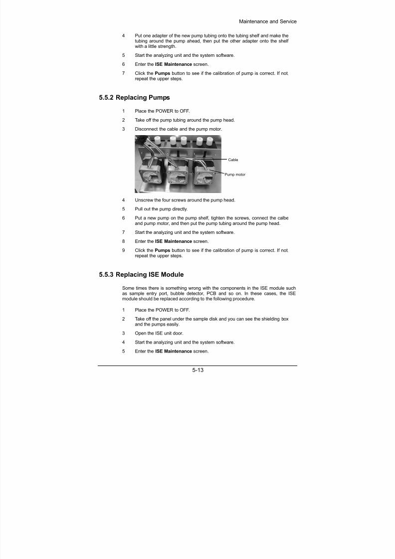
3 Disconnect the cable and the pump motor.
Pump motor
Cable
4 Unscrew the four screws around the pump head.
5 Pull out the pump directly.
6 Put a new pump on the pump shelf, tighten the screws, connect the calbeand pump motor, and then put the pump tubing around the pump head.
7 Start the analyzing unit and the system software.
8 Enter the ISE Maintenance screen.
9 Click the Pumps button to see if the calibration of pump is correct. If not,repeat the upper steps.
5.5.3 Replacing ISE Module
Some times there is something wrong with the components in the ISE module suchas sample entry port, bubble detector, PCB and so on. In these cases, the ISEmodule should be replaced according to the following procedure.
1 Place the POWER to OFF.
2 Take off the panel under the sample disk and you can see the shielding boxand the pumps easily.
3 Open the ISE unit door.
4 Start the analyzing unit and the system software.
5 Enter the ISE Maintenance screen.

8/20/2019 Mindray BS 300 Analizor Service Manual
http://slidepdf.com/reader/full/mindray-bs-300-analizor-service-manual 46/119
Maintenance and Service
5-14
6 Click the Maintenance button.
7 Place the POWER to OFF.
8 Unscrew the screw of the ISE module and take off the cover.
9 Take off all electrodes from above to below.
10 Disconnect the right angle adapter and the compression plate.
11 Disconnect the cable.
12 Unscrew the four screws that fix the ISE module to the shielding box. Thentake out the module from the shielding box.
13 Put a new ISE module to the shielding box. Then connect the cable andinstall the electrodes sequentially. At last mount the right angle adapter tothe compression plate.
14 Install the electrodes sequentially.
15 Enter the System Maintenance screen of the system software.
16 Select the Others tab and click the Download Settings button.
17 Enter the ISE Maintenance screen.
18 Click the A purge button to see if there is solution leaking out. If there is,take off the electrodes and install them again.
19 Check if the new ISE module can work normally.
8/20/2019 Mindray BS 300 Analizor Service Manual
http://slidepdf.com/reader/full/mindray-bs-300-analizor-service-manual 47/119
Software Introduction
6-1
6 Software Introduction
The software of BS-300 analyzer is composed of the system software and the control
software.
6.1 System Software
The system software can, according to the requirements and inputs of users,generate a work schedule (instruction sequence), control the units of analyzing unit inthe sequence of instructions in the work schedule, receive photoelectric data,response messages or execution results from the analyzing unit, output them to thePC screen or the printer. With these outputs, users can obtain correct test results.
According to different functions, the entire PC software system can be divided into the
following parts:
System Initialization
This part includes the initialization of the PC operating system, the initialization of thecommunication between the PC and analyzing unit, and the controls of analyzing unitreset.
Control system
This part includes the formation of the work schedule, instruction data sending andreceiving.
GUI
This part includes the requests for tests (routine tests, emergency tests, calibrationtests and QC tests), the observation of test status (status of the reaction disk, sampledisk and reagent disk), test management, calibration management, QC management,result query, alarm management and the help system.
Shutdown Processing
This part includes the resets of sub-units.
6.1.1 System initialization
To initialize the PC operating system,
Check the PC operating system. The system software must run under Windows2000 or Windows XP. Otherwise, the system will prompt that the system softwarecannot run under other operating system, and then the system software systemexits automatically.
Check the current screen resolution for the operating system. The system software
must run under the resolution of 1024 × 768. Otherwise, the system prompts toreset the resolution before restarting the system software and exit the systemsoftware.
Disable the screen protection program. The system software must keep displayedwhile running. To prevent the screen protection program from disturbing users inthe operating and observing processes, disable it.
Lock the keyboard. When running, the system software will lock some keycombinations to prevent users from starting any other program and conducting any

8/20/2019 Mindray BS 300 Analizor Service Manual
http://slidepdf.com/reader/full/mindray-bs-300-analizor-service-manual 48/119
Software Introduction
6-2
other operation. In this case, users cannot switch over to any other program orprint the current screen.
Check whether there is any username and password of themaintenance/debugging personnel in the registry. The system software has thedebugging function. Only the authorized maintenance/debugging personnel canenter the debugging window and maintain or debug the system and the host. For
the confidentiality, the username and password are saved in the registry. If theyare unavailable in the registry, the system will re-write the default username andpassword into the registry.
To initialize the communication and the units auto-check,
Set serial ports and initialize them, including such parameters as the baud rate,data bit, start bit, stop bit, parity bit, transmitting/receiving buffer, control protocoland so on. In addition, start the serial port receiving thread.
Handshake for communication. Send a handshake instruction to the analyzing unit.If the analyzing unit responds to this instruction (namely, send back a handshake
instruction to the PC), it indicates the PC handshakes with the host successfully. Ifthe host fails to respond to handshake instruction, it will re-send the handshakeinstruction back in a specific period. If it fails for continuously three times, thesystem will prompt to exit the system software. If you ignore that and continue toenter the system software, all tests cannot be conducted under the system.
Check whether the printer is connected. If not, the system will prompt to connect it.
Send an instruction for querying the auto-check results of the units, check theauto-check result of each unit. (The units are auto-checked when the analyzingunit is started, and the auto-check results are stored in the main unit.) In case ofany fault data in the auto-check result of any unit, the system will prompt to switchoff the analyzing unit and check the faulty unit.
6.1.2 Shutdown processing
In the BS-300 Chemistry Analyzer Control System window, click the Exit button.The Confirm dialog box appears. If you click OK, the system will
Switch off the lamp;
Unload all reaction cuvettes;
Wash the fluid tubing;
Reset all units;
Unlock the keyboard;
Prompt to exit the operating system and shut down the PC.
6.2 Control Software
The analyzing unit can be functionally divided into the following units: photoelectricunit, reaction disk unit, reagent disk unit, sample disk unit, reagent probe syringe unit,sample probe syringe unit, mixing bar unit, loading and manipulator unit, temperaturecontrol unit, fluid tubing unit and reagent refrigeration unit. The functions of thoseunits are listed in the following table.

8/20/2019 Mindray BS 300 Analizor Service Manual
http://slidepdf.com/reader/full/mindray-bs-300-analizor-service-manual 49/119
Software Introduction
6-3
Unit Function
Main unit Receives macroinstructions from the PC, decomposes theminto a series of action instructions, and then delivers theaction instructions to destination sub-units (in specific order)at a certain interval.
Monitors the status of other units, and transmits datacollected by the photoelectric unit to the PC.
Photoelectricunit
Photoelectrically detects, amplifies and converts the solutionin reaction cuvettes, and stores A/D converted data at thetwin port FIFO for the main unit to read and transmit them tothe PC.
Reaction diskunit
Contains 80 cuvette No.
Runs the reaction cuvette with the specified No., followingthe instruction of the main unit, to the reagent dispensingposition, sample dispensing position, mixing position, andphotoelectric detection position at all wavelengths.
Reagent diskunit
Contains 50 bottle positions.
Carries reagents, and runs the reagent bottles with specifiedNo., following the instruction of the main unit, to the reagentaspirating position.
Sample diskunit
Contains 60 tube positions in the inner and outer circles.
Carries samples, and runs the sample tubes with specifiedNo., following the instruction of the main unit, to the sampleaspirating position.
Reagent probe
syringe unit
Receives instructions from the PC, and controls the reagent
probe in aspirating a specific volume of reagent from thereagent bottle and dispensing it to the specified reactioncuvette.
Sample probesyringe unit
Receives instructions from the PC, and controls the sampleprobe in aspirating a specific volume of sample from thesample tube and dispensing it to the specified cuvette.
Mixing bar unit Receives instructions from the PC, and controls the mixingbar in mixing the solution in the cuvette that has been run tothe mixing position.
Runs the mixing bar to the wash well, and wash it after eachmixing process to avoid carryover.
Loading andmanipulatorunit
Controls the cuvette feeder and manipulator.
The feeder assembly is responsible for detecting whetherthere are enough reaction cuvettes in the cuvettescompartment and pushing reaction cuvettes to the positionfor the manipulator to take cuvettes.
The manipulator is responsible for taking reaction cuvettesfrom the reaction disk, placing them into the used cuvettebucket, taking new reaction cuvettes from the cuvettecompartment, and putting them on the reaction disk.

8/20/2019 Mindray BS 300 Analizor Service Manual
http://slidepdf.com/reader/full/mindray-bs-300-analizor-service-manual 50/119
Software Introduction
6-4
Unit Function
Temperaturecontrol unit
Controls the reaction disk temperature, reagent probepreheating temperature and fluid tubing.
Note: The reaction disk temperature should be kept at 37 ,the heating cavity of the reagent probe should be preheated
to 45.
Fluid tubing unit Controls the fluid tubing in washing the reagent probe,sample probe and mixing bar.
Reagentrefrigerationunit
Refrigerates the reagent chamber and controls itstemperature between 4 ~ 10 .

8/20/2019 Mindray BS 300 Analizor Service Manual
http://slidepdf.com/reader/full/mindray-bs-300-analizor-service-manual 51/119
Service Flow
7-1
7 Service Flow
WARNING:
Before disassembling or assembling the analyzing unit, ensure thePOWER is placed to OFF.
The probe tip is sharp and can cause puncture wounds. To preventinjury, exercise caution when working around the probe.
When you disassemble or replace any board, ensure to wear antistaticgloves.
BIOHAZARD:
Wear gloves and lab coat and, if necessary, goggles.
7.1 Fluid Level Detection Failure of Reagent Probe
Surface
detection
failure of
reagent
probe(Th
e reagent
probe
does not
detect
the
surface
on the
reaction
disk.)
Thereagent
probe
cannot
detect
the
surface
on the
reagent
disk
The
reagent
probe mis-
detected
the surface
Surface detection signal transmission error: The surface detection
board does not have the working voltage, or when the probe touches
the surface, the indicator of the surface detection board is normal, but
there is always a host alarm indicating surface detection failure.
Possible cause: The patch cord for the reagent surface detection is
disconnected, or the connector is not well connected.
Surface detection signal processing error: When the probe touches
the surface, the indicator of the surface detection board is normal, the
connection between the main control board and the surface detection
board is normal, and no surface detection signal reaches the maincontrol board, but there is always a host alarm indicating surface
detection failure.
Possible cause: Main control board.
Surface detection board failure: When there is no probe
failure, but the indicator is always on, or the indicator is
not on when the probe touches the surface, there must
be a surface detection board failure.
Troubleshooting: Replace the surface detection board.
Power failure: The working voltage of the surface
detection board is 12V. In case of no power supply, the
surface detection signal cannot be generated.
Possible cause: Disconnection; the connector is not well
connected; there is no 12V output from the main control
board.
Probe failure: The detection terminal has a changeable
capacitance. Loose exterior or interior of the probe, the
sealing-off of the probe connecting wire and the probe
breakage will result in unsteady voltage or obvious
voltage changes. In this case, the capacitance signalwill be unavailable or exceed the range of the surface
detection board.
Possible cause: Reagent probe assembly, connector.
The surface
detection
signal fails
to be
generatedby
capacitance
change.
When this failure occurs, the sample probe cannot detect
the surface at the reaction disk, but there is no alarm at
the reagent unit. For details, see Surface Detection
Failure: Sample Probe.
8/20/2019 Mindray BS 300 Analizor Service Manual
http://slidepdf.com/reader/full/mindray-bs-300-analizor-service-manual 52/119
Service Flow
7-2
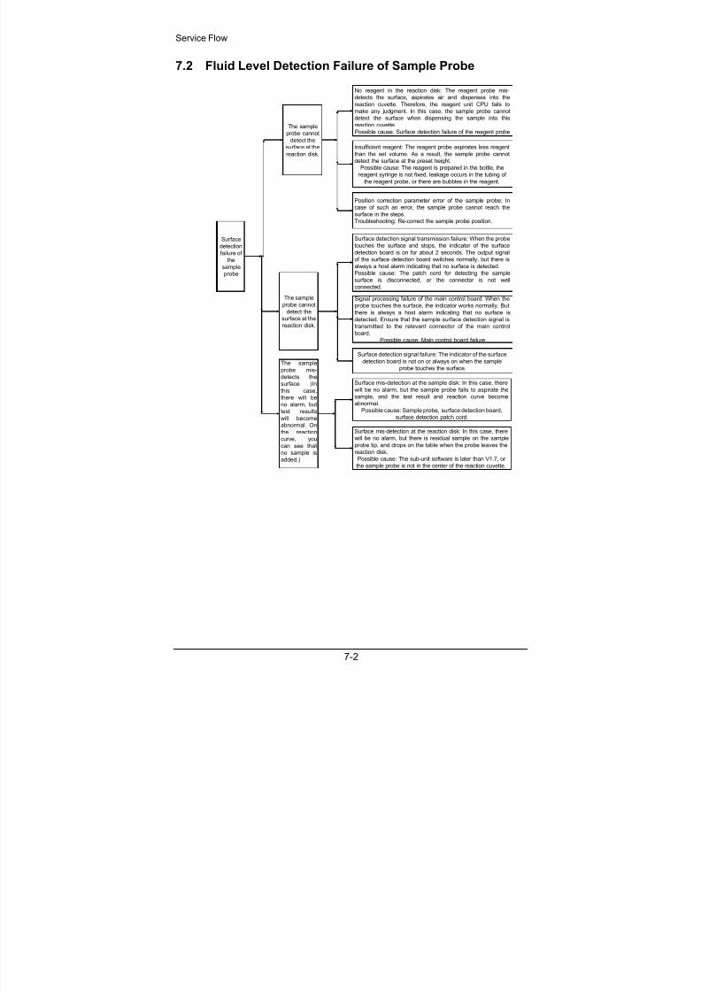
7.2 Fluid Level Detection Failure of Sample Probe
Surface
detectionfailure of
the
sample
probe
The sample
probe cannot
detect the
surface at the
reaction disk.
The sample
probe cannot
detect the
surface at the
reaction disk.
The sample
probe mis-detects the
surface (In
this case,
there will be
no alarm, but
test results
will become
abnormal. On
the reaction
curve, you
can see that
no sample is
added.)
No reagent in the reaction disk: The reagent probe mis-
detects the surface, aspirates air and dispenses into the
reaction cuvette. Therefore, the reagent unit CPU fails to
make any judgment. In this case, the sample probe cannot
detect the surface when dispensing the sample into this
reaction cuvette.
Possible cause: Surface detection failure of the reagent probe
insufficient reagent: The reagent probe aspirates less reagent
than the set volume. As a result, the sample probe cannot
detect the surface at the preset height.
Possible cause: The reagent is prepared in the bottle, the
reagent syringe is not fixed, leakage occurs in the tubing of
the reagent probe, or there are bubbles in the reagent.
Position correction parameter error of the sample probe: In
case of such an error, the sample probe cannot reach the
surface in the steps.
Troubleshooting: Re-correct the sample probe position.
Surface detection signal transmission failure: When the probe
touches the surface and stops, the indicator of the surfacedetection board is on for about 2 seconds. The output signal
of the surface detection board switches normally, but there is
always a host alarm indicating that no surface is detected.
Possible cause: The patch cord for detecting the sample
surface is disconnected, or the connector is not well
connected.
Surface detection signal failure: The indicator of the surface
detection board is not on or always on when the sample
probe touches the surface.
Surface mis-detection at the sample disk: In this case, there
will be no alarm, but the sample probe fails to aspirate the
sample, and the test result and reaction curve become
abnormal.
Possible cause: Sample probe, surface detection board,
surface detection patch cord.
Signal processing failure of the main control board: When the
probe touches the surface, the indicator works normally. But
there is always a host alarm indicating that no surface is
detected. Ensure that the sample surface detection signal is
transmitted to the relevant connector of the main control
board.
Possible cause: Main control board failure
Surface mis-detection at the reaction disk: In this case, there
will be no alarm, but there is residual sample on the sample
probe tip, and drops on the table when the probe leaves the
reaction disk.
Possible cause: The sub-unit software is later than V1.7, or
the sample probe is not in the center of the reaction cuvette.
8/20/2019 Mindray BS 300 Analizor Service Manual
http://slidepdf.com/reader/full/mindray-bs-300-analizor-service-manual 53/119
Service Flow
7-3
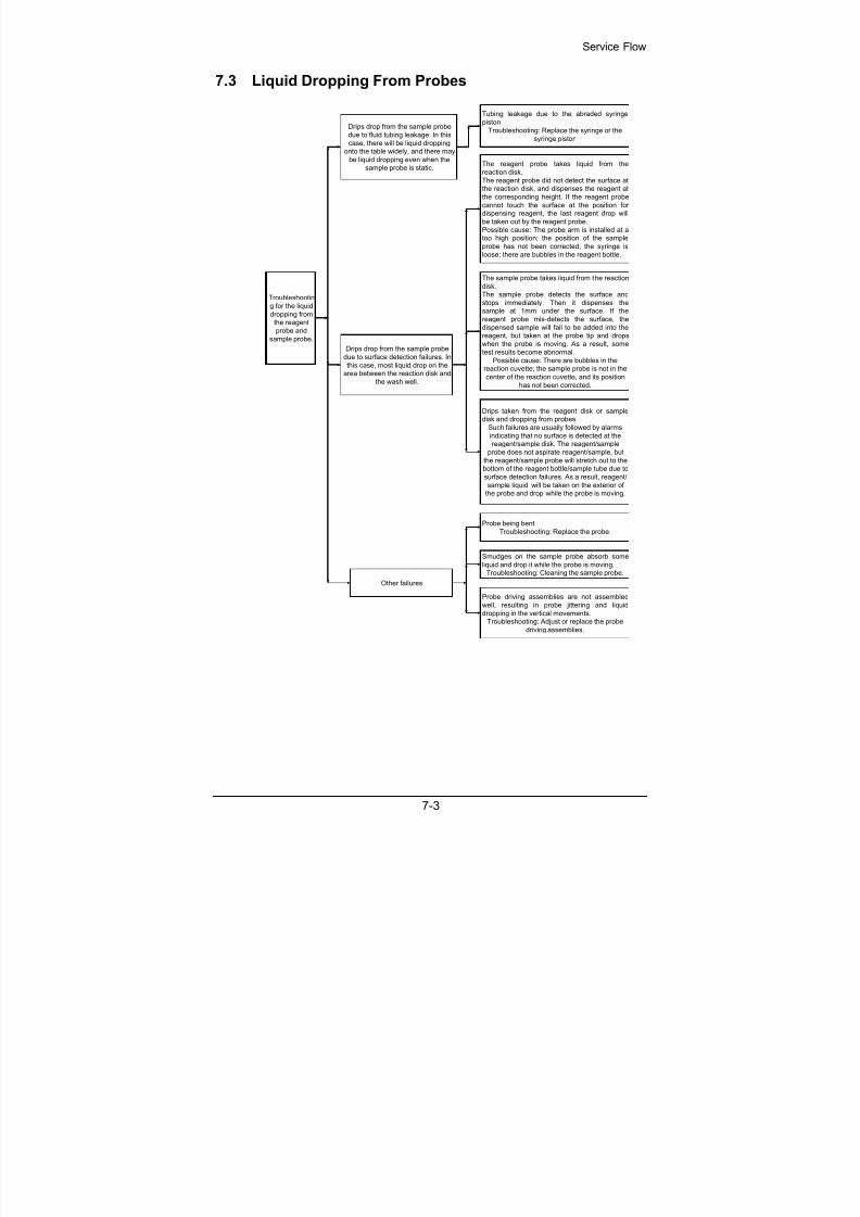
7.3 Liquid Dropping From Probes
Troubleshooting for the liquid
dropping fromthe reagent
probe and
sample probe.
Tubing leakage due to the abraded syringe
piston
Troubleshooting: Replace the syringe or the
syringe piston
The reagent probe takes liquid from the
reaction disk.
The reagent probe did not detect the surface atthe reaction disk, and dispenses the reagent at
the corresponding height. If the reagent probe
cannot touch the surface at the position fordispensing reagent, the last reagent drop will
be taken out by the reagent probe.
Possible cause: The probe arm is installed at atoo high position; the position of the sample
probe has not been corrected; the syringe is
loose; there are bubbles in the reagent bottle.
Probe being bent
Troubleshooting: Replace the probe.
The sample probe takes liquid from the reaction
disk.The sample probe detects the surface and
stops immediately. Then it dispenses thesample at 1mm under the surface. If the
reagent probe mis-detects the surface, the
dispensed sample will fail to be added into thereagent, but taken at the probe tip and drops
when the probe is moving. As a result, some
test results become abnormal.
Possible cause: There are bubbles in thereaction cuvette; the sample probe is not in the
center of the reaction cuvette, and its position
has not been corrected.
Probe driving assemblies are not assembled
well, resulting in probe jittering and liquid
dropping in the vertical movements.Troubleshooting: Adjust or replace the probe
driving assemblies.
Drips taken from the reagent disk or sampledisk and dropping from probes
Such failures are usually followed by alarms
indicating that no surface is detected at thereagent/sample disk. The reagent/sample
probe does not aspirate reagent/sample, butthe reagent/sample probe will stretch out to thebottom of the reagent bottle/sample tube due to
surface detection failures. As a result, reagent/
sample liquid will be taken on the exterior ofthe probe and drop while the probe is moving.
Other failures
Drips drop from the sample probe
due to fluid tubing leakage. In this
case, there will be liquid dropping
onto the table widely, and there maybe liquid dropping even when the
sample probe is static.
Drips drop from the sample probe
due to surface detection failures. In
this case, most liquid drop on thearea between the reaction disk and
the wash well.
Smudges on the sample probe absorb some
liquid and drop it while the probe is moving.Troubleshooting: Cleaning the sample probe.

8/20/2019 Mindray BS 300 Analizor Service Manual
http://slidepdf.com/reader/full/mindray-bs-300-analizor-service-manual 54/119
Service Flow
7-4
7.4 Failing to Detect Level of Water for Washing Exteriors
Surface detection signal failure:
See relevant resolutions for the
surface detection failure.
No water in the
wash well
Reagent or sample probe.
Solution: Replace a probe
Failing to
Detect the
Surface of
the Water
forWashing
Exteriors
No water in the wash water tank: Users
can see this failure in the alarm
information detergent empty . In case of
no alarm information, check whether
there is any problem in the detergent tank
cover assembly.
Pump damaged: In this case, there will
be no water in the three wash wells.
Troubleshooting: Replace the pump.
Tubing blocked: In this case, there will be
insufficient water for washing exteriors,
the three water flows are not the same, or
there will be no water in any of the three
wash wells.
Possible cause: The unidirectional valve
is blocked, or the detergent entrance is
blocked.
The tube is disconnected.
Possible cause: The tube is degraded, or
other causes.
Troubleshooting: Connect the tubes
again.

8/20/2019 Mindray BS 300 Analizor Service Manual
http://slidepdf.com/reader/full/mindray-bs-300-analizor-service-manual 55/119
Service Flow
7-5
7.5 Abnormal Results
7.5.1 All Results Being Abnormal
All test
results are
abnormal
All results are
lower than
normal
results.
Some results
are higher,
and some are
lower, with
bad
repeatability.
No sample or insufficient sample is added.
In this case, it can be seen on the reaction curve that
the absorbance has not increased in the period for
adding the sample. The reaction curve is even, and
many results are 0.
Possible cause: Sample probe blocked, tubing
leakage, syringe not fixed, valve not shut tightly.
The reaction is not thorough.
If the sample is not mixed uniformly with the reagent,
the reaction will not be thorough, and the light cannot
detect the changes of the absorbance.
Possible cause: The mixing bar did not mix the
reacting liquid.
The volumes of dispensed sample are not the same.
In this case, it can be seen from the reaction curve
that the response is proportional to the volume of the
sample.
Possible cause: Tubing leakage, valve not shut
tightly, or cuvette segments not cleaned well.
7.5.2 Some Results Being Abnormal
Some test results are
abnormal.
Good repeatability
Troubleshooting: Re-calibrate it.
Bad repeatability
Observe the reaction curve, and find the possible
causes.
All test results are approaching to 0.
Observe the reaction curve first.
Possible cause: The lamp base of correspondingwavelength exceeds 65535; the photoelectric
detection unit fails to detect the change of
absorbance, reagent failure and optical fiber
disconnection.

8/20/2019 Mindray BS 300 Analizor Service Manual
http://slidepdf.com/reader/full/mindray-bs-300-analizor-service-manual 56/119
Service Flow
7-6
7.5.3 Several Results Being Abnormal
Several test results are
abnormal
Several test results are too low.
In this case, observe the reaction curve first.
Possible cause: Drips dropping from the sample
probe
Several test results suddenly become too high.
In this case, observe the reaction curve first.
Possible cause: There are bubbles in the current
cuvette; the mixing bar knocks the cuvettes.

8/20/2019 Mindray BS 300 Analizor Service Manual
http://slidepdf.com/reader/full/mindray-bs-300-analizor-service-manual 57/119
Service Flow
7-7
7.6 Insufficient Light Intensity of Lamp
Estimate whether the
lamp has worked for
2000h (lifetime),
replace Lamb Replace the lamp.
Check whether the AD value of the
channel whose lamp vase value is
smaller increases obviously.
Record the lamp background value and gain
Measure and record the lamp background value and gain
Replace lamb
Insufficient Light
Intensity of the Lamp
Lamp background values of all
channels decreases.
Lamp base values of several
channels decreases
Adjust the gain parameter to make the
lamp base AD values of all channel
lamps increase to about 62000.
Y E
S
YES
Replace the lamp with
the original lamp
Replace the photoelectric transducerassembly, and then check whether the
lamp base value increases obviously.
Replace the
photoelectric
transducer assembly.Change the positions with the
smaller fiber end, and check
whether the lamp base value
increases obviously.
Check whether the photometric
system (such as the lens)
corresponding to the fiber channelis covered with dirt or the like. (If
yes, clean it.) Then check whether
the lamp base value increases
obviously
Replace the optical
fiber
Clean thephotometric system
(such as the lens)
Remove the fault alarm
N O
YES
NO
YES
N O
YES
Note:
Do not adjust the photoelectric gain parameter in case you have no idea about thecause for the alarm indicating insufficient light intensity of the lamp.
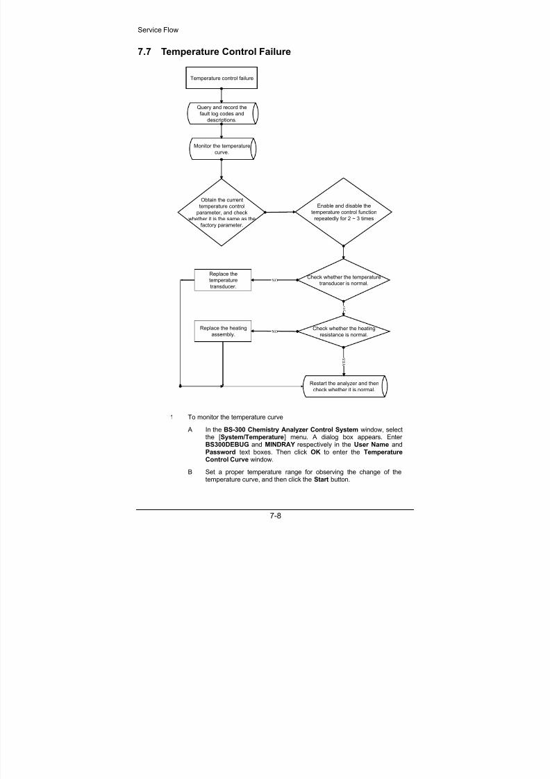
8/20/2019 Mindray BS 300 Analizor Service Manual
http://slidepdf.com/reader/full/mindray-bs-300-analizor-service-manual 58/119
Service Flow
7-8
7.7 Temperature Control Failure
Temperature control failure
Query and record the
fault log codes and
descriptions.
Monitor the temperature
curve.
Obtain the current
temperature control
parameter, and check
whether it is the same as the
factory parameter.
Enable and disable the
temperature control function
repeatedly for 2 ~ 3 times
Check whether the temperature
transducer is normal.
Check whether the heating
resistance is normal.
Replace the
temperature
transducer.
Replace the heating
assembly.
Restart the analyzer and thencheck whether it is normal.
y e s
NO
NO
Y E S
To monitor the temperature curve
A In the BS-300 Chemistry Analyzer Control System window, selectthe [System/Temperature] menu. A dialog box appears. EnterBS300DEBUG and MINDRAY respectively in the User Name andPassword text boxes. Then click OK to enter the TemperatureControl Curve window.
1
B Set a proper temperature range for observing the change of the
temperature curve, and then click the Start button.

8/20/2019 Mindray BS 300 Analizor Service Manual
http://slidepdf.com/reader/full/mindray-bs-300-analizor-service-manual 59/119
Service Flow
7-9
C Minimize the Temperature Control Curve window for futureobservation at any time.
D After that, print or snap the temperature curve and then return it tothe headquarters together with the service work report.
To measure the impedance of the temperature transducer
A Switch off the BS-300 analyzer.
B Open the left side plate of the BS-300 analyzing unit to expose themain control board.
C Unplug J45 (reagent preheating temperature transducer), andmeasure the resistance between PIN1 and PIN3 with a multimeter.
The relation between the resistance and the temperature is: 25
/1100Ω, 38.5/1145Ω, 45/1170Ω, 50/1170Ω.
2
D Unplug J44 (reaction disk temperature transducer), and measure theresistance between PIN1 and PIN3 with a multimeter. The relation
between the resistance and the temperature is: 25/1100Ω, 38.5
/1145Ω, 45/1170Ω, 50/1170Ω.
To measure the resistance of the heater
A Measure the impedance of the reagent preheater in the followingprocedures:
Unplug J24 (power driving board)
Measure the impedance between PIN1 and PIN2. Reagent preheater(BA30-10-06626)/24.6 to 28.5Ω.
3
B Measure the impedances of the upper and lower heaters of thereaction disk in the following procedures:
Disconnect the connecting wire from J113 of the power patchingboard.
Measure the impedances of the upper and lower heater: uppertemperature-sensitive heater (BA30-10-06624)/437.8 to 483.8Ω,lower temperature-sensitive heater (BA30-10-06625)/131.4 to145.2Ω.
7.8 Bar Code Scanner (optional) Failure
WARNING:
Light sent by the bar code scanner may hurt your eyes. Do not stareinto the laser beam from the bar code scanner.
If the bar code scanner cannot emit laser, you can service it according to the followingsteps.
1 Place sample tubes with bar code labels that meet the requirementsmentioned in the operation manual.
2 Restart the analyzer.

8/20/2019 Mindray BS 300 Analizor Service Manual
http://slidepdf.com/reader/full/mindray-bs-300-analizor-service-manual 60/119
Service Flow
7-10
3 Enter the Scanner Setup & Maintenance screen of the system software.
4 Enter the Maintenance tab.
5 Enter the sample position range in the Sample Position field and click theStep Scan button. Observe if the scanner can emit laser. If not, click theLaser on button. If the scanner still cannot emit laser, go to the next step.
If the bar code scanner emits laser normally but is failed in reading, you can service itaccording to the following steps.
1 Place the ANALYZING UNIT POWER to OFF.
2 Place sample tubes with bar code labels that meet the requirementsmentioned in the operation manual.
3 See if the window on the sample department is stained. If so, clean thewindow with absolute alcohol-dipped gauze and go to the next step. If not,go to the step 8.
4 Restart the analyzer.
5 Enter the Scanner Setup & Maintenance screen of the system software.
6 Enter the Maintenance tab.
7 Enter the sample position range in the Sample Position field and click theStep Scan button. Observe the scanning procedures to see if the scannercan read the bar codes. If not, go to the next step.
8 Enter the Setup tab.
9 Select all symbologies but do not select any Check or Length.
10 Enter the Maintenance tab.
11 Click the Scan button to see if the scanner can read the bar codes. If not,go to the next step.
12 Place the test fixture to the position 28 on the sample disk.
13 Click the Mechanism button at the System Maintenance screen to resetall mechanical parts. If the laser from the scanner cannot reach the barcode through the slit on the test fixture, adjust the screws on the brackets until the laser from the scanner can reach the bar code.

8/20/2019 Mindray BS 300 Analizor Service Manual
http://slidepdf.com/reader/full/mindray-bs-300-analizor-service-manual 61/119
Service Flow
7-11
Bracket 1
Bracket 2
14 If the scanner cannot read the bar codes successfully, replace the bar codescanner. If the new scanner cannot read the bar code, you need to checkthe bar code labels the user used.
7.9 Feeder Failure
7.9.1 Transducer Distribution of the Feeder
Pressure Transducer
No-Cuvette
Transducer
Cuvette-Pushing
Limit Transducer Insufficient-Cuvette
Transducer
Cuvette-taking limit
transducer

8/20/2019 Mindray BS 300 Analizor Service Manual
http://slidepdf.com/reader/full/mindray-bs-300-analizor-service-manual 62/119
Service Flow
7-12
7.9.2 Feeder Failure
Feeder failure
symptom
The trolley moves
backward to the
end, but does notmove forward.
Possible causes:
1. The cuvette-taking limit signal has not been
detected.
2. The belt is too tight, so the motor cannot run.
Troubleshooting:1. Check whether the voltage is 0 when the
cuvette-taking limit optical coupler is blocked.
2. Adjust the position of the motor to loosen the
belt.
The trolley moves
forward and stops
before compacting
the cuvette
segment
1. The moving resistance is too large, so the
trolley fails to compact the cuvette segment, but
the pressure transducer has been blocked.
2. The sliding block falls off, resulting in large
friction.
3. The motor cannot work normally.
4. The belt is too tight.
Troubleshooting:
1. Clean the guiding axis of the trolley.
2. Replace the sliding block assembly.
3. Replace the motor.
4. Loosen the belt.
The trolley keeps
moving backward
and forward
1. The no-cuvette transducer has not been
pressed completely, so the system deems that
the cuvette compartment is empty, and the
trolley moves back for cuvette segments.
Troubleshooting:
1. Adjust the position of the no-cuvette
transducer.
2. Replace the feeder assemblies.

8/20/2019 Mindray BS 300 Analizor Service Manual
http://slidepdf.com/reader/full/mindray-bs-300-analizor-service-manual 63/119
Service Flow
7-13
7.9.3 Manipulator Failure
Manipulator
Failure
Manipulator vertical-
movement error:
Cannot reach/leave the
initial position.
The signal of the vertical optical coupler
has not been detected after the motor
runs for specified steps.
Possible causes:
1. The resistance of the lead screw is too
large (frequently).2. The optical couplers for the vertical
initial position cannot work (scarcely).
3. The vertical motor of the manipulator
cannot work (scarcely).
4. The optical coupler connector is not
connected well (infrequently).
5. The power driving board cannot work
(infrequently).
6. The main control board cannot work
(scarcely).
Troubleshooting:1. Lubricate the
lead screw after
cleaning it.
2. Replace
relevant
assemblies.
The lower hand of the
manipulator cannot
close/open.
Direct cause:
The finger signal has
not been detected afterthe electromagnet of
the manipulator is
switched on.
1. The operator has added too many
cuvette segments into the feeder (behind
the trolley). When the trolley moves
backward, the jaw is pressed back by the
cuvette segments; when it moves forward
again, the hand fails to open in time, so
the jaw may press one side of the trolley
only. As a result, the cuvette segment at
the front fails to corporate with the upper
hand of the manipulator well (frequently).2. The lower hand of the manipulator fails
to corporate with the reaction disk
position well (frequently).
3. The snap ring of the manipulator is not
flexible (infrequently).
4. The lower hand coupler of the
manipulator cannot work any more
(scarcely).
1. Press the
cuvette-taking
key after adding
cuvette
segments into
the feeder.
2. Adjust the
positions of thelower hand and
reaction disk.
3. Replace the
manipulator (Its
position must be
adjusted)
The upper hand of the
manipulator cannot
close/open.
Direct cause:
The finger signal has
not been detected afterthe electromagnet of
the manipulator is
switched on.
1. The snap ring of the manipulator is not
flexible (infrequently).
2. The coupler of the upper finger cannot
work any more (scarcely).
3. The upper hand of the manipulator is
not arranged well with the position of thefeeder/reaction disk (frequently).
4. The coupler connector is not
connected well (infrequently).
1. Adjust the
positions of the
upper hand and
the feeder/
reaction disk.
2. Replace themanipulator (Its
position must be
adjusted).
The upper/lower hand
of the manipulator
accidentally closes/
opens.
Direct cause:
After the manipulator is
switched on, the finger
coupler signal is
received, but the signal
changes suddenly
while the manipulator
is moving.
1. The snap ring of the manipulator is not
flexible (frequently).
2. The finger coupler of the manipulator
cannot work any more (scarcely).
Troubleshooting:
1. Replace the
manipulator (Its
position must be
adjusted).
7.10 Troubleshooting of ISE Unit (optional)
When there is something wrong with the ISE unit, an error code will be displayed atthe screen and saved in the log. The error code of the ISE unit has a format of 7 ASCII characters, the format of which is <1234567>.
Each digit represents a certain error.
Digit 1: Air in sample, Calibrant A, Calibrant B, Bubble Detector, mV range. Digit 2: Sample/Calibrant B mV range.

8/20/2019 Mindray BS 300 Analizor Service Manual
http://slidepdf.com/reader/full/mindray-bs-300-analizor-service-manual 64/119
Service Flow
7-14
Digit 3: mV out of range for Calibrant A in Sample Cycle, or Calibrant B in UrineCycle.
Digit 4: Noise in mV of Calibrant B in Calibration Cycle, or Sample mV during aSample Cycle.
Digit 5: mV Noise in Calibrant A of the Calibration Cycle, or Sample Cycle, mVNoise in Calibrant B of the Urine Cycle.
Digit 6: mV Drift of calibrant A.
Digit 7: Slope of Sample value is out of range.
Each row represents where the error locates in.
You can find all the seven numbers in the table below digit by digit and then knowwhat is wrong with the ISE unit. 0 means no error.
For example, when you see <0001000>, you only need to find where the “1” locatesin the Digit 4 column and you will see it locates in the Na+ row. So you will know thecause of this error is the noise in mV of Calibrant B or sample related to the Na
+
electrode.
Digit 1 Digit 2 Digit 3 Digit 4 Digit 5 Digit 6 Digit 7Error
Air/Hardware
mV Out
Calib/Sample
mV Out
Cal A inCalib/SampleMode,Cal B inUrineMode
mVNoise
CalB/Sample
mVNoise
Cal A inCalib/SampleMode,Cal B inUrineMode
Cal ADrift
inSampleMode,Cal B inUrineMode
Out ofSlope/MachineRanges
Air inSample/Urine
S 0 0 0 0 0 0
Air in Calibrant A A 0 0 0 0 0 0
Air in Calibrant B B 0 0 0 0 0 0
Air in Cleaner C 0 0 0 0 0 0
Air in Segment M 0 0 0 0 0 0
Pump Calibration P 0 0 0 0 0 0
No Flow F 0 0 0 0 0 0
Bubble Detector D 0 0 0 0 0 0
Reagent ChipRead
R 0 0 0 0 0 0
Reagent ChipWrite
W 0 0 0 0 0 0
Store CalibrationValue Error
Q 0 0 0 0 0 0
Command Error T 0 0 0 0 0 0
No Error 0 0 0 0 0 0 0
Na+ 0 1 1 1 1 1 1

8/20/2019 Mindray BS 300 Analizor Service Manual
http://slidepdf.com/reader/full/mindray-bs-300-analizor-service-manual 65/119
Service Flow
7-15
Digit 1 Digit 2 Digit 3 Digit 4 Digit 5 Digit 6 Digit 7Error
Air/Hardware
mV Out
Calib/Sample
mV Out
Cal A inCalib/SampleMode,Cal B inUrineMode
mVNoise
CalB/Sample
mVNoise
Cal A inCalib/SampleMode,Cal B inUrineMode
Cal ADrift
inSampleMode,Cal B inUrineMode
Out ofSlope/MachineRanges
K+ 0 2 2 2 2 2 2
Na+, K+ 0 3 3 3 3 3 3
Li+ 0 4 4 4 4 4 4
Li+, Na+ 0 5 5 5 5 5 5
Li+, K+ 0 6 6 6 6 6 6
Li+, K+, Na+ 0 7 7 7 7 7 7
Cl- 0 8 8 8 8 8 8
Cl-, Na+ 0 9 9 9 9 9 9
Cl-, K+ 0 A A A A A A
Cl-, Li+ 0 B B B B B B
Cl-, K+, Na+ 0 C C C C C C
Cl-, Li+, Na+ 0 D D D D D D
Cl-, Li+, K+ 0 E E E E E E
Cl-, Li+, K+, Na+ 0 F F F F F F
The following table displays the causes and the correction measures of some errors.Note that if the correction measure is the replacement of board, bubble detector orother components in the ISE unit, you have to replace the whole ISE unit. You canrefer to the chapter 5 for detailed information about some replacement procedures.
Symptom Problem Correction
1. No power
2. Communication failure Turn off the system and thenstart it again.
3. RS232 cable is disconnectedor damaged.
Move the panel of analyzing unitand reconnect or replace cablebetween the ISE unit and themain control board.
4. Module connector has beendamaged.
Replace board.
System does notrespond
5. Component failure on board. Replace board.

8/20/2019 Mindray BS 300 Analizor Service Manual
http://slidepdf.com/reader/full/mindray-bs-300-analizor-service-manual 66/119
Service Flow
7-16
Symptom Problem Correction
1. Misalignment of electrodes Remove and replace electrodes<45 mV/decade to reseatproperly.
2. Deterioration of calibratorsolutions Replace Calibrant B first andretest. If still low, replaceCalibrant A and retest.
3. Deterioration of sensingelectrode (low slope)
Replace problem electrodesand test.
4. Air bubble on referenceelectrode membrane
Remove electrode, tap todislodge bubble, replace, andrecalibrate.
5. Deterioration of referenceelectrode
Replace reference electrodeand retest.
Low Slope
Na+, K+, or Li+ <45mV/decade
Cl- <35 mV/decade
or
High Slope
Na+, K+, or Li+ >63mV/decade
Cl- >60 mV/decade
6. Module or fluid temperaturesexceed 37° C. (high slope) Monitor temperature. Changeinstrument location if ambient istoo great.
1. Deterioration of sensingelectrode
Replace problem electrodesand test.
Noise Error Flag
Single electrode
2. Electrical noise spike fromenvironmental source
a) Check for electrical noisecoincident with activation.
b) Check grounding of Module.
c) Component failure on Moduleboard. Replace board.
1. Deterioration of referenceelectrode
Replace reference electrodeand retest.
Noise Error Flag
Multiple electrodes
2. Electrical noise spike fromenvironmental source
a) Check for electrical noisecoincident with activation.
b) Check grounding of Module.
c) Component failure on Moduleboard. Replace board.
1. May occur when newelectrode or new bottle ofCalibrant A is installed by
system.
Purge the Calibrant A andrecalibrate the module. If theelectrode is new it may initially
drift as it rehydrates over thecourse of 15 minutes.
Drift Error Flag
Single electrode
2. Deterioration of sensingelectrode
Replace the problem electrodeand test.
1. May occur when newelectrode or new bottle ofCalibrant A is installed onsystem.
Purge Calibrant A andrecalibrate the Module.
Drift Error Flag
Multiple electrodes
2. Deterioration of referenceelectrode.
Replace reference electrodeand retest.

8/20/2019 Mindray BS 300 Analizor Service Manual
http://slidepdf.com/reader/full/mindray-bs-300-analizor-service-manual 67/119
Service Flow
7-17
Symptom Problem Correction
3. Electrical spike fromenvironmental source.
a) Check for electrical noisecoincident with activation.
b) Check grounding of Module.
c) Component failure on Moduleboard. Replace the board.
1. Insufficient sample pipettedinto Module sample entry port
a) Host instrument must deliver70 µL. Increase dispensedvolume.
b) Operator must placesufficient sample in sample cupto account for all testsprogrammed.
c) Fluid leak in electrodes.
Air in Sample
2. Sample not positioned a) Electrodes not seatedproperly. Reseat electrodes.
b) Pump tubing aging. Replace.
c) Pump tubing obstructed ortubing length is excessive.
1. Sample and Calibrant A aresegmented with air.
a) Electrodes are not properlyseated or compressed. Checkcompression plate, spring andseal. Reseat electrodes.
b) Ensure that all electrodes
and o-rings are in place.
2. Fibrin or salt is plugging theelectrode flow path.
a) Use Cleaning procedure forModule.
b) Disassemble Module andclean or replace electrode withplugged flow path.
3. Bubble detector ismalfunctioning.
Replace bubble detector.
Air in Sample andCalibrant A
4.Waste pump ismalfunctioning.
Replace waste pump.
Air in Calibrant B and Air in Calibrant A
1. Calibrant B and Calibrant Aare segmented with air.
a) Electrodes are not properlycompressed. Checkcompression plate, spring andseal.
b) Ensure that all electrodesand o-rings are in place.
c) Ensure tubing is connectedproperly.
d) Replace tubing.

8/20/2019 Mindray BS 300 Analizor Service Manual
http://slidepdf.com/reader/full/mindray-bs-300-analizor-service-manual 68/119
Service Flow
7-18
Symptom Problem Correction
2. Fibrin or salt is plugging theelectrode flow path.
a) Use Cleaning procedure forModule.
b) Disassemble Module and
clean or replace electrode withplugged flow path.
3. Waste pump malfunction. Replace waste pump, tubing.
4. Bubble Detector malfunction. Replace bubble detector.
1. Calibrant A pouch is empty. Replace Calibrant A with a newone, purge and recalibrate.
2. Tubing is disconnected. Reconnect or replace tubing.
3. Calibrant A pump is notworking properly.
a) Check electrical connections.
b) Replace pump tubing.
c) Replace motor.
Air in Calibrant A (no“Air” errors reported forSample or Calibrant B)
4. Tubing is plugged, split orcrimped.
Replace tubing

8/20/2019 Mindray BS 300 Analizor Service Manual
http://slidepdf.com/reader/full/mindray-bs-300-analizor-service-manual 69/119
Mechanical Structure
8-1
8 Mechanical Structure
Reaction disk motorReagent disk motorSynchronous belts
Coder sensors

8/20/2019 Mindray BS 300 Analizor Service Manual
http://slidepdf.com/reader/full/mindray-bs-300-analizor-service-manual 70/119
Mechanical Structure
8-2
Reagent probe assemblySample probe assemblyMixing bar assembly
Reagent cooling assembly

8/20/2019 Mindray BS 300 Analizor Service Manual
http://slidepdf.com/reader/full/mindray-bs-300-analizor-service-manual 71/119
Mechanical Structure
8-3
Lamb assembly Big head of fiber
Fan of Lamb assembly
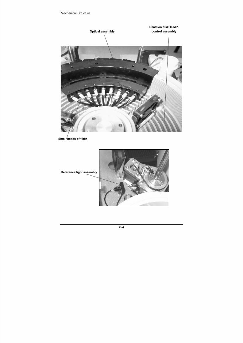
8/20/2019 Mindray BS 300 Analizor Service Manual
http://slidepdf.com/reader/full/mindray-bs-300-analizor-service-manual 72/119
Mechanical Structure
8-4
Optical assembly
Reaction disk TEMP.
control assembly
Small heads of fiber
Reference light assembly
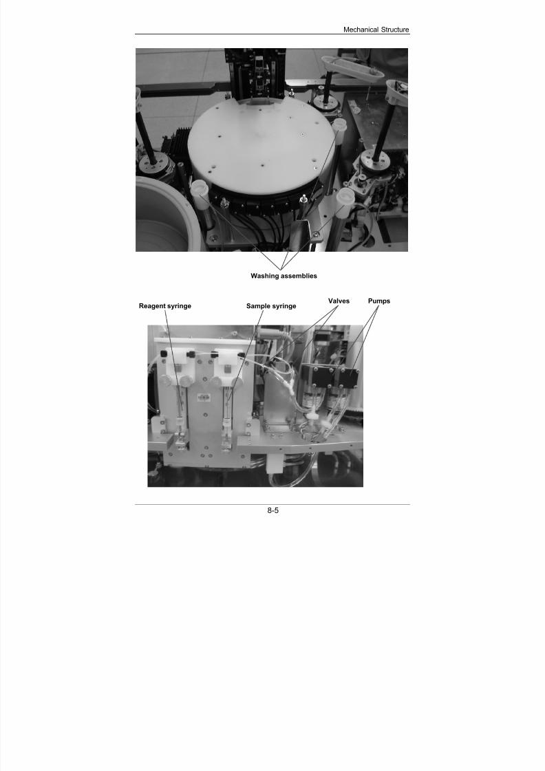
8/20/2019 Mindray BS 300 Analizor Service Manual
http://slidepdf.com/reader/full/mindray-bs-300-analizor-service-manual 73/119
Mechanical Structure
8-5
Washing assemblies
PumpsSample syringeReagent syringe
Valves

8/20/2019 Mindray BS 300 Analizor Service Manual
http://slidepdf.com/reader/full/mindray-bs-300-analizor-service-manual 74/119
Mechanical Structure
8-6
A/D conversion board
Reagent refrigeration board
Main control board Power drive board

8/20/2019 Mindray BS 300 Analizor Service Manual
http://slidepdf.com/reader/full/mindray-bs-300-analizor-service-manual 75/119
Mechanical Structure
8-7
Loading system
Manipulator
assembly

8/20/2019 Mindray BS 300 Analizor Service Manual
http://slidepdf.com/reader/full/mindray-bs-300-analizor-service-manual 76/119
Mechanical Structure
8-8
Top of mixing assembly
Top of sample assembly
Top of reagent assembly
Bar code scanner (optional)
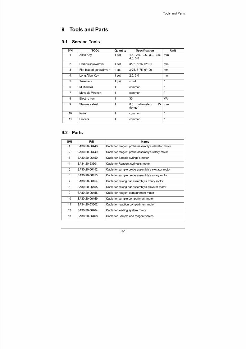
8/20/2019 Mindray BS 300 Analizor Service Manual
http://slidepdf.com/reader/full/mindray-bs-300-analizor-service-manual 77/119
Tools and Parts
9-1
9 Tools and Parts
9.1 Service Tools
S/N TOOL Quantity Specification Unit
1 Allen Key 1 set 1.5, 2.0, 2.5, 3.0, 3.5,4.0, 5.0
mm
2 Phillips screwdriver 1 set 3*75, 5*75, 6*100 mm
3 Flat-bladed screwdriver 1 set 3*75, 5*75, 6*100 mm
4 Long Allen Key 1 set 2.5, 3.0 mm
5 Tweezers 1 pair small /
6 Multimeter 1 common /
7 Movable Wrench 1 common /
8 Electric iron 1 30 VA
9 Stainless steel 1 0.5 (diameter), 15(length)
mm
10 Knife 1 common /
11 Pincers 1 common /
9.2 Parts
S/N P/N Name
1 BA30-20-06448 Cable for reagent probe assembly’s elevator motor
2 BA30-20-06449 Cable for reagent probe assembly’s rotary motor
3 BA30-20-06450 Cable for Sample syringe’s motor
4 BA34-20-63601 Cable for Reagent syringe’s motor
5 BA30-20-06452 Cable for sample probe assembly’s elevator motor
6 BA30-20-06453 Cable for sample probe assembly’s rotary motor
7 BA30-20-06454 Cable for mixing bar assembly’s rotary motor
8 BA30-20-06455 Cable for mixing bar assembly’s elevator motor
9 BA30-20-06458 Cable for reagent compartment motor
10 BA30-20-06459 Cable for sample compartment motor
11 BA34-20-63602 Cable for reaction compartment motor
12 BA30-20-06464 Cable for loading system motor
13 BA30-20-06468 Cable for Sample and reagent valves
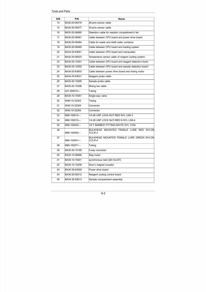
8/20/2019 Mindray BS 300 Analizor Service Manual
http://slidepdf.com/reader/full/mindray-bs-300-analizor-service-manual 78/119
Tools and Parts
9-2
S/N P/N Name
14 BA30-20-06476 26-pins sensor cable
15 BA30-20-06477 34-pins sensor cable
16 BA30-20-06480 Detection cable for reaction compartment’s fan
17 BA30-20-06481 Cable between CPU board and power drive board
18 BA30-20-06484 Cable for waste and distill water container
19 BA30-20-06485 Cable between CPU board and loading system
20 BA34-20-63651 Cable between CPU board and manipulator
21 BA30-20-06523 Temperature sensor cable of reagent cooling system
22 BA30-20-15291 Cable between CPU board and reagent detection board
23 BA30-20-15292 Cable between CPU board and sample detection board
24 BA34-20-63603 Cable between power drive board and mixing motor
25 BA34-20-63631 Reagent probe cable
26 BA30-20-15295 Sample probe cable
27 BA30-20-15296 Mixing bar cable
28 A21-000010--- Tubing
29 BA30-10-15051 Single-way valve
30 0040-10-32303 Tubing
31 0040-10-32304 Connector
32 0040-10-32305 Connector
33 M90-100014--- 1/4-28 UNF LOCK NUT-RED NYL LNS-3
34 M90-100015--- 1/4-28 UNF LOCK NUT-RED N NYL LNS-4
35 M90-100030--- 1/8 Y BARBED FITTING-WHITE NYL Y230-
36M90-100050---
BULKHEAD MOUNTED FEMALE LURE RED NYLONCCLR-3
37M90-100051---
BULKHEAD MOUNTED FEMALE LURE GREEN NYLONCCLR-4
38 M90-100071--- Tubing
39 BA30-30-15169 5-way connector
40 BA30-10-06666 Step motor
41 BA30-10-15041 synchronous belt (220 XL037)
42 BA30-10-15258 Door’s magnet (couple)
43 BA34-30-63559 Power drive board
44 BA30-30-06312 Reagent cooling control board
45 BA34-30-63613 Sample compartment assembly

8/20/2019 Mindray BS 300 Analizor Service Manual
http://slidepdf.com/reader/full/mindray-bs-300-analizor-service-manual 79/119
Tools and Parts
9-3
S/N P/N Name
46 BA30-10-06365 Halogen Lamb (50W)
47 BA30-30-06691 REF pre-amplification board
48 BA30-30-15228 340nm amplification assembly
49 BA30-10-06367 Filter 340
50 BA30-30-06673 340nm pre-amplification board
51 BA30-30-15229 405nm pre-amplification assembly
52 BA30-10-06368 Filter 405
53 BA30-30-06675 405 pre-amplification board
54 BA30-30-15230 450nm pre-amplification assembly
55 BA30-10-06369 Filter 450
56 BA30-30-06677 450 pre-amplification board
57 BA30-30-15231 510nm pre-amplification assembly
58 BA30-10-06370 Filter 510
59 BA30-30-06679 510 pre-amplification board
60 BA30-30-15232 546nm pre-amplification assembly
61 BA30-10-06371 Filter 546
62 BA30-30-06681 546 pre-amplification board
63 BA30-30-15233 578nm pre-amplification assembly
64 BA30-10-06372 Filter 578
65 BA30-30-06683 578 pre-amplification board
66 BA30-30-15234 630nm pre-amplification assembly
67 BA30-10-06373 Filter 630
68 BA30-30-15235 630 pre-amplification board
69 BA30-30-15235 670nm pre-amplification assembly
70 BA30-10-06374 Filter 670
71 BA30-30-06687 670 pre-amplification board
72 BA30-30-15236 700nm pre-amplification assembly
73 BA30-10-06375 Filter 700
74 BA30-30-06689 700 pre-amplification board
75 BA30-30-06565 Drive assembly of sample probe
76 BA34-30-63637 Syringe assemply
77 3100-10-49438 100ul Syringe
78 BA30-10-06651 500ul Syringe
79 BA30-10-15115 Step motor

8/20/2019 Mindray BS 300 Analizor Service Manual
http://slidepdf.com/reader/full/mindray-bs-300-analizor-service-manual 80/119
Tools and Parts
9-4
S/N P/N Name
80 BA30-20-06594 3-way connector for syringe
81 BA30-21-15161 Sensor cable for reagent syringe
82 BA30-21-15162 Sensor cable for sample syringe
83 BA30-30-06634 Mixing bar assembly
84 BA30-21-15159 Cable for mixing bar assembly’s elevator motor
85 BA30-21-15160 Cable for mixing bar assembly’s rotary motor
86 BA30-30-06639 Fans of lamb assembly
87 BA30-30-06641 Washing pool assembly
88 0040-10-32302 Connector
89 0040-10-32303 Washer
90 BA30-21-15311 Valves assembly (KNF)
91 BA30-30-06702 Reaction compartment assembly
92 BA30-30-06715 A/D converter assembly
93 BA30-30-06752 Rocker of reagent probe
94 BA30-30-06304 Liquid detection board
95 BA30-30-06753 Reagent probe assembly
96 BA30-30-06761 Heat-block assembly
97 BA30-30-06768 Rocker of sample probe
98 BA30-30-14978 Sample probe assembly
99 BA30-30-06770 Rocker of mixing bar
100 BA34-20-63653 Loading system assembly
101 BA30-21-06488 Pressure sensor and cable for loading system
102 BA30-21-06490 Cable for cuvette-pushing limit transducer
103 BA30-21-06491 Cable for cuvette-taking limit transducer
104 BA30-21-06492 Cable for insufficient-cuvette transducer
105 BA34-20-63648 Board for loading system
106 BA30-21-06489 Cable for no-cuvette transducer
107 BA30-30-15034 Code sensor of reaction compartment
108 BA30-30-15095 Reagent compartment assembly
109 BA30-30-06780 Reagent disk handle assembly
110 BA30-30-15113 Driving assembly of reagent probe
111 BA30-21-15155 Sensor cable for reagent probe’s up-down sensor
112 BA30-21-15156 Sensor cable for reagent probe’s rotary sensor
113 BA30-30-15166 Coder sensor for reagent disk
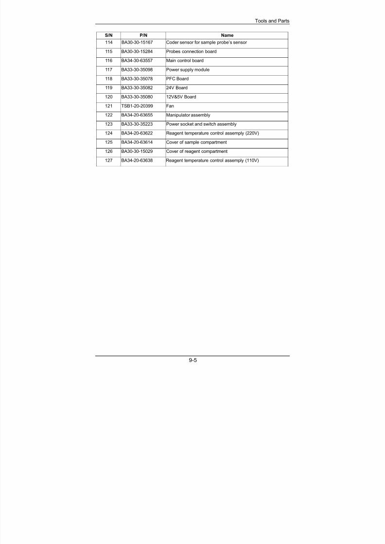
8/20/2019 Mindray BS 300 Analizor Service Manual
http://slidepdf.com/reader/full/mindray-bs-300-analizor-service-manual 81/119
Tools and Parts
9-5
S/N P/N Name
114 BA30-30-15167 Coder sensor for sample probe’s sensor
115 BA30-30-15284 Probes connection board
116 BA34-30-63557 Main control board
117 BA33-30-35098 Power supply module
118 BA33-30-35078 PFC Board
119 BA33-30-35082 24V Board
120 BA33-30-35080 12V&5V Board
121 TSB1-20-20399 Fan
122 BA34-20-63655 Manipulator assembly
123 BA33-30-35223 Power socket and switch assembly
124 BA34-20-63622 Reagent temperature control assemply (220V)
125 BA34-20-63614 Cover of sample compartment
126 BA30-30-15029 Cover of reagent compartment
127 BA34-20-63638 Reagent temperature control assemply (110V)

8/20/2019 Mindray BS 300 Analizor Service Manual
http://slidepdf.com/reader/full/mindray-bs-300-analizor-service-manual 82/119

8/20/2019 Mindray BS 300 Analizor Service Manual
http://slidepdf.com/reader/full/mindray-bs-300-analizor-service-manual 83/119
Maintenance And Test Software
10-1
10 Maintenance And Test Software
10.1 General
The maintenance and test software of the BS-300 Chemistry Analyzer is thesoftware that helps maintenance personnel debug and maintain the BS-300Chemistry Analyzer. Maintenance personnel can, through this software, checkwhether the probes, mixing bar, disks, fluidic system and photometric system ofthe BS-300 Chemistry Analyzer work normally, modify parameters, and executeindividual commands or combined commands.
Run the NewDebug.exe file to enter the Maintenance and Test window. SeeFigure 10-1.
Figure 10-1 Maintenance and Test window
Display Area
As shown in Figure 10-1, there are 4 tabs in the Maintenance and Test window:
Command
PARA and Speed
Temperature
Photoelectric

8/20/2019 Mindray BS 300 Analizor Service Manual
http://slidepdf.com/reader/full/mindray-bs-300-analizor-service-manual 84/119
Maintenance And Test Software
10-2
Note:
The buttons displayed in gray in software interface are notfunctional.
Following is a brief introduction to the software interface.
Display area
At the bottom of the window is the display area for displaying the frameinformation and fault/error information. The upper box is for frame information, andthe lower one is for fault/error information.
There are five types of frame information, including Result, Echo, Data,Command and Warning.
Select the check box in front of frame information to display relevant frameinformation. Click the check box again to de-select, and the frame information willnot be displayed.
Click the Clear button to clear the information displayed in relevant box. The twoClear buttons are respectively for two boxes.
Setup button
Click the Setup button at up right corner to show a dialog as shown in Figure 10-2,which is used to change communication port and set baud rate and check sumtype of the port. Check sum type includes odd, even and none.
Figure 10-2 Serial Port Setup
Communication Port
Baud Rate Check Sum Type
About… button
Clicking the About… button at up right corner of the interface, you can view theversion information of this software.
In the following sections, the 4 tabs mentioned above will be detailed respectively.
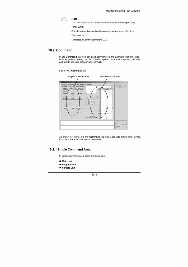
8/20/2019 Mindray BS 300 Analizor Service Manual
http://slidepdf.com/reader/full/mindray-bs-300-analizor-service-manual 85/119
Maintenance And Test Software
10-3
Note:
The units of parameters involved in this software are respectively:
Time: 50ms;
Sample (reagent) aspirating/dispensing volume: steps of motors;
Temperature:.
Temperature control coefficient: 0.01.
10.2 Command
In the Command tab, you can send commands to the analyzing unit and checkwhether probes, mixing bar, disks, fluidic system, photometric system, ISE unitand built-in bar code scanner work normally.
Figure 10-3 Command tab
Single Command Area Macroinstruction Area
As shown in Figure 10-3, the Command tab mainly consists of two parts: SingleCommand Area and Macroinstruction Area.
10.2.1 Single Command Area
In Single Command Area, there are 8 sub-tabs:
Main Unit
Reagent Unit Sample Unit
8/20/2019 Mindray BS 300 Analizor Service Manual
http://slidepdf.com/reader/full/mindray-bs-300-analizor-service-manual 86/119
Maintenance And Test Software
10-4
Load Unit
Temp Unit
Photoelectric Unit
ISE Module
Sample Bar Code Module
Check the analyzing unit for their counterparts.
There are several buttons in each tab. Click a button and you can send acommand to the counterpart on the analyzing unit.
Note:
After starting this software, you must click the Downloadparameters to Analyzing Unit button in the Main Unit sub-tab.Otherwise, the software will not operate the analyzing unit
successfully. After clicking the Enable modifying parameters button in the MainUnit sub-tab, you can modify the parameters in the PARA andSpeed tab.
Following are instructions to the action implemented by each command.
Main Unit
Command What it does
Download parameters to
Analyzing Unit
Configures running parameters for the
analyzing unit.
Reset all mechanical parts Moves all units of the analyzing unit to theirinitial position, and cleans reagent probe,sample probe and mixing bar.
Enable modifyingparameters
Switches on the switch for modifying parameterthrough this operation before modifyingparameter at PARA and Speed tab.
Disable modifyingparameters
Switches off the switch for modifying parameterthrough this operation after modifyingparameter at PARA and Speed tab.
Handshake with AnalyzingUnit
Checks that the communication cable worksnormally.
Send a direct instruction Edits and sends user-defined commands.
Reagent Unit
Command What it does
Reagent probe wash Cleans the reagent probe.
Pump, valve (interior) on Turns on the pump and the valves that controlflow of washing the interior of reagent probe.
8/20/2019 Mindray BS 300 Analizor Service Manual
http://slidepdf.com/reader/full/mindray-bs-300-analizor-service-manual 87/119
Maintenance And Test Software
10-5
Command What it does
Pump, valve (interior) off Turns off the pump and the valves that controlflow of washing the interior of reagent probe.
Pump, valve (exterior) on Turns on the pump and the valve that controlflow of washing the exterior of reagent probe.
Pump, valve (exterior) off Turns off the pump and the valve that controlflow of washing the exterior of reagent probe.
Probe above reaction disk Moves the reagent probe above the reactiondisk.
Probe above outer circle Moves the reagent probe above the outer circleof reagent disk.
Probe above inner circle Moves the reagent probe above the inner circleof reagent disk.
Probe tip above bottle top
(outer circle)
Moves the reagent probe until the probe tip a
few millimeters above the top of the reagentbottle in the outer circle of reagent disk.
Probe tip above bottle top(inner circle)
Moves the reagent probe until the probe tip afew millimeters above the top of the reagentbottle in the inner circle of reagent disk.
Probe down to outer circle Moves the reagent probe down to the reagentbottle in the outer circle of reagent disk.
Probe down to inner circle Moves the reagent probe down to the reagentbottle in the inner circle reagent disk.
Probe down to reaction disk Moves the reagent probe down to the cuvettein the reaction disk.
Probe tip above cuvette top Moves the reagent probe until the probe tip afew millimeters above the top of cuvette in thereaction disk.
Probe down to wash well Moves the reagent probe to its washingposition.
Probe above wash well Moves the reagent probe to the top of washwell.
Reagent disk rotate Rotates the reagent disk for specified circlesand stop it at specified bottle position. Inputrotating circles in the first box and position No.
in the second box.
Reagent disk rotate toposition
Rotates the reagent disk to specified bottleposition. Input position No. in the box.
Reagent syringe init Moves the reagent syringe to its initial position.
Reagent syringe full Moves the reagent syringe to its largest travel.
Reagent syringe empty Empties the reagent syringe.
Reagent unit reset Cleans the reagent probe and rotates thereagent disk to position No. 1.
8/20/2019 Mindray BS 300 Analizor Service Manual
http://slidepdf.com/reader/full/mindray-bs-300-analizor-service-manual 88/119
Maintenance And Test Software
10-6
Sample Unit
Command What it does
Sample probe wash Cleans the sample probe.
Pump, valve (interior) on Turns on the pump and the valves that controlflow of washing the interior of sample probe.
Pump, valve (interior) off Turns off the pump and the valves that controlflow of washing the interior of sample probe.
Pump, valve (exterior) on Turns on the pump and the valve that controlflow of washing the exterior of sample probe.
Pump, valve (exterior) off Turns off the pump and the valve that controlflow of washing the exterior of sample probe.
Probe above wash well Moves the sample probe to the top of washwell.
Probe above reaction disk Moves the sample probe to the top of reaction
disk.
Probe above outer circle Moves the sample probe above the outer circleof sample disk.
Probe above inner circle Moves the sample probe above the inner circleof sample disk.
Probe tip above tube top(outer circle)
Moves the sample probe until the probe tip afew millimeters above the top of the tube in theouter circle of sample disk.
Probe tip above tube top(inner circle)
Moves the sample probe until the probe tip afew millimeters above the top of the tube in the
inner circle of sample disk.Probe tip above cuvette top Moves the sample probe until the probe tip a
few millimeters above the top of cuvette in thereaction disk.
Probe down to reaction disk Moves the sample probe down to the reactioncuvette in reaction disk.
Probe down to wash well Moves the sample probe to its washingposition.
Probe down to outer circle Moves the sample probe down to the tube inthe outer circle of sample disk.
Probe down to inner circle Moves the sample probe down to the tube inthe inner circle of sample disk.
Sample disk rotate Rotates the sample disk for specified circlesand stop it at specified tube position. Inputrotating circles in the first box and position No.in the second box.
Sample disk rotate toposition
Rotates the sample disk to specified tubeposition. Input position No. in the box.
Sample syringe init Moves the sample syringe to its initial position.
Sample syringe empty Empties the sample syringe.
Sample syringe full Moves the sample syringe to its largest travel.

8/20/2019 Mindray BS 300 Analizor Service Manual
http://slidepdf.com/reader/full/mindray-bs-300-analizor-service-manual 89/119
Maintenance And Test Software
10-7
Command What it does
Sample unit reset Cleans the sample probe and rotate the sampledisk to position No. 1.
Load Unit
Command What it does
Mixer to the top of wash well Moves the mixing bar to the top of wash well.
Mixer move into wash well Moves the mixing bar to its washing position.
Mixer move to the top ofreaction disk
Moves the mixing bar to the top of reactiondisk.
Mixer move into reactiondisk
Moves the mixing bar to mixing position inreaction disk.
Mixer stir for a while Mixing bar stirs for a specified period.
Mixing bar rotates for a whileabove wash well
Moves the mixing bar above its wash well andthen rotates it for a specified period.
Take new cuvettes Moves the compartment trolley backwards toget new cuvettes.
Load New cup Rotates the reaction disk to specified position,then get new cuvettes with the manipulator andput them in reaction disk.
Unload cup Rotates the reaction disk to specified position,then get the cuvettes in reaction disk with themanipulator and put them in used-cuvette
bucket.
Motion of manipulator fingers Tightens or loosen manipulator’s fingers(grabbing mechanism).
After entering a value of 0-3 to the box, clickthe button and the fingers will motions. 0means both fingers tighten; 1 means the upperloosen and the lower tightens; 2 means theupper tightens and the lower loosens; and 3means both loosen.
Manipulator to vertical init.pos.
Moves the manipulator to vertical initialposition.
Manipulator to horiz. init.pos.
Moves the manipulator to horizontal initialposition.
To H-pos. for taking cuvettes Moves the manipulator to horizontal position forgetting cuvettes.
To V-pos. for taking cuvettes Moves the manipulator to vertical position forgetting cuvettes.
To H-position for placingcuvettes
Moves the manipulator to horizontal position forplacing cuvettes.
To V-position for placing
cuvettes
Moves the manipulator to vertical position for
placing cuvettes.

8/20/2019 Mindray BS 300 Analizor Service Manual
http://slidepdf.com/reader/full/mindray-bs-300-analizor-service-manual 90/119
Maintenance And Test Software
10-8
Command What it does
Move steps vertically Moves the manipulator for specified steps invertical way.
Move steps horizontally Moves the manipulator for specified steps inhorizontal way.
Loader unit reset Moves the mixing bar to its initial position,loosen manipulator’ grabbing mechanism andmove the manipulator to its initial position.
Temp Unit
Command What it does
Temperature control on Turns on the specified temperaturecontroller(s).
There’re two temperature controllers as
Reaction Disk and Reagent PreHeat.
Selects the check box(es) in front of acontroller(s), click the button, you can turn onthe selected controller(s).
Temperature control off Turns off the specified temperaturecontroller(s).
There’re two temperature controllers asReaction Disk and Reagent PreHeat.
Selects the check box(es) in front of acontroller(s), click the button, you can turn off
the selected controller(s).
Photoelectric Unit
Command What it does
Reaction disk rotate Rotates the reaction disk for specified circlesand stop it at specified cuvette position. Inputrotating circles in the first box and position No.in the second box.
Reaction disk rotate somepositions
Rotates the reaction disk for specified cuvettepositions, and input number of cuvettepositions in the box.
Rotate and measure Rotates the reaction disk, collects reaction dataduring rotating, and then stops it at specifiedcuvette position.
Turn on light Turns on the light.
Turn off light Turns off the light.
Test dark current Turns off the light and measures the darkcurrent at this time. The dark current data willbe displayed in the box below.

8/20/2019 Mindray BS 300 Analizor Service Manual
http://slidepdf.com/reader/full/mindray-bs-300-analizor-service-manual 91/119
Maintenance And Test Software
10-9
Command What it does
Test base current Unloads the first segment of cuvettes inreaction disk with manipulator, then rotates thereaction disk and during rotating measures thelight where places the first segment of cuvettesbefore. The data regarding base current will bedisplayed in the box below.
ISE Module
Command What it does
Handshake The ISE unit shakes hands with the main unit.
Maintain Executes the maintaining cycle to run the waste pump untilthe electrode flow path is cleared of fluid.
Detect Bubble Checks to see if the bubble detector is functioningproperly.
Cleaning Period Removes protein build-up from the ISE Module electrodes.
Calibrate Calibrates the electrodes of the ISE Module.
Correct Pumps Calibrates the peristaltic pumps of the ISE Module.
Measure Serum Measures serum or plasma samples on the ISE Module.
A Purge Purges Calibrant A solution through the tubing from thepouch of Calibrant A to the ISE Module.
B Purge Purges Calibrant B solution through the tubing from thepouch of Calibrant B to the ISE Module.
<DSPA> Pumps 200µl of Calibrant A to make it convenient for youto aspirate it from the sample entry port.
<SWBC> Displays the result of bubble detector checking for the lasttime.
<SWPC> Displays the result of pump correction for the last time.
<CKSM> Displays the software version of the ISE unit.
<DVON> After clicking this button, the results in mv will also bedisplayed when calibration, measurement or a sip cycle isfinished.
<MVON> After clicking this button, the results in mv will also bedisplayed when calibration or measurement is finished.
<DVFF> Disables the effect of clicking <DVON> or <MVON>.
Sample Bar Code Module
Command What it does
Set Select a symbology from the pull down list and click thisbutton. If Valid is selected, the symbology will be set as theone that the scanner can recognize. Otherwise, it will bethe one that can not be recognized.
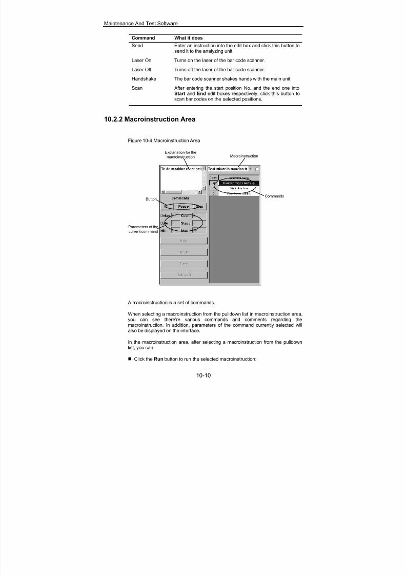
8/20/2019 Mindray BS 300 Analizor Service Manual
http://slidepdf.com/reader/full/mindray-bs-300-analizor-service-manual 92/119
Maintenance And Test Software
10-10
Command What it does
Send Enter an instruction into the edit box and click this button tosend it to the analyzing unit.
Laser On Turns on the laser of the bar code scanner.
Laser Off Turns off the laser of the bar code scanner.
Handshake The bar code scanner shakes hands with the main unit.
Scan After entering the start position No. and the end one intoStart and End edit boxes respectively, click this button toscan bar codes on the selected positions.
10.2.2 Macroinstruction Area
Figure 10-4 Macroinstruction Area
Explanation for the
macroinstruction Macroinstruction
CommandsButton
Parameters of the
current command
A macroinstruction is a set of commands.
When selecting a macroinstruction from the pulldown list in macroinstruction area,you can see there’re various commands and comments regarding themacroinstruction. In addition, parameters of the command currently selected willalso be displayed on the interface.
In the macroinstruction area, after selecting a macroinstruction from the pulldownlist, you can
Click the Run button to run the selected macroinstruction;

8/20/2019 Mindray BS 300 Analizor Service Manual
http://slidepdf.com/reader/full/mindray-bs-300-analizor-service-manual 93/119
Maintenance And Test Software
10-11
Click the Pause button to suspend the macroinstruction which is running;
Click the Stop button to stop the macroinstruction which is running.
Note:
After all commands in each macroinstruction are executed, thesystem counts it as one time.
When the check box on the right of the macroinstruction pulldownlist is selected, the selected macroinstruction will be executed foronce; otherwise, the macroinstruction will be executed cyclically.
For each macroinstruction, the commands of it are executed one by one in thesequence in which they are listed. When the set delay expires after a command isexecuted, the next command is executed immediately. In case of an error in theexecution process, the macroinstruction will be stopped.
Following are instructions to the action implemented by each macroinstruction.
Macroinstruction Command What it does
B purge Purges Calibrant B solutionthrough the tubing from thepouch of Calibrant B to theISE Module.
A,B purge
A purge Purges Calibrant A solutionthrough the tubing from thepouch of Calibrant A to the
ISE Module.Reagent probe abovewash well
Moves the reagent probeabove its wash well.
Valve on, Pump on Turns on the pump and valvethat control the flow ofwashing the exterior ofreagent probe.
Check exterior fluidpath of reagentprobe
Pump off, Valve off Turns off the pump and valvethat control the flow ofwashing the exterior ofreagent probe.
Sample probe abovewash well
Moves the sample probeabove its wash well.
Valve on, Pump on Turns on the pump and valvethat control the flow ofwashing the exterior ofsample probe.
Check exterior fluidpath of sampleprobe
Pump off, Valve off Turns off the pump and valvethat control the flow ofwashing the exterior ofsample probe.

8/20/2019 Mindray BS 300 Analizor Service Manual
http://slidepdf.com/reader/full/mindray-bs-300-analizor-service-manual 94/119
Maintenance And Test Software
10-12
Macroinstruction Command What it does
Reagent probe abovewash well
Moves the reagent probeabove its wash well.
Valve on, Pump on Turns on the pump andvalves that control the flow of
washing the interior ofreagent probe.
Check interior fluidpath of reagentprobe
Pump off, Valve off Turns off the pump andvalves that control the flow ofwashing the interior ofreagent probe.
Sample probe abovewash well
Moves the sample probeabove its wash well.
Valve on, Pump on Turns on the pump andvalves that control the flow ofwashing the interior of
sample probe.
Check interior fluidpath of sampleprobe
Pump off, Valve off Turns off the pump andvalves that control the flow ofwashing the interior ofsample probe.
Test Loader Reload cup looply The manipulator gets newcuvettes from thecompartment looply, and thenput them in the reaction disk.
Reaction disk to nextcup
The reaction disk rotates andstops. No. of position for
reaction disk to stop at willincrease.
Mix instruction The mixing bar moves intoreaction cuvette and mixesfor a specified period.
Test mixing bar inreaction disk
Mixer to vertical init The mixing bar moves tovertical initial position.
Reaction disk to nextcup
The reaction disk rotates andstops. No. of position forreaction disk to stop at willincrease.
Reagent probe toreaction disk
The reagent probe movesvertically into bottom ofreaction cuvette.
Test reagent probein reaction disk
Reagent probe tovertical init
The reagent probe moves tovertical initial position.
Test sample probe inreaction disk
Reaction disk to nextcup
The reaction disk rotates andstops. No. of position forreaction disk to stop at willincrease.

8/20/2019 Mindray BS 300 Analizor Service Manual
http://slidepdf.com/reader/full/mindray-bs-300-analizor-service-manual 95/119
Maintenance And Test Software
10-13
Macroinstruction Command What it does
Sample probe toreaction disk
The sample probe movesvertically into bottom ofreaction cuvette.
Sample probe to
vertical init
The sample probe moves to
vertical initial position.
Reagent disk inposition 50 in nextperiod
Reagent disk rotates toposition 50 and in the nextperiod the reagent probe willaspirate urine diluent from theposition.
Dispensing 270µl ofurine diluent
Reagent probe aspirates207µl of urine diluent anddispenses it to a cuvette.
Dispensing 30µl ofurine sample
Sample probe aspirates 30µlof urine sample and
dispenses it to a cuvette. Themixing bar stirs it.
Washing mixing bar Washes the mixing bar.
First period Sample probe aspirates 70µlof diluted urine to the ISEunit.
Second period Sample probe aspirates 70µlof diluted urine to the ISEunit.
Third period Washes the sample probe.
Idle period Measuring.
Idle period Measuring.
Urine test (autodiluted)
Idle period Measuring.
First period Sample probe aspirates 70µlof diluted urine to the ISEunit.
Second period Sample probe aspirates 70µlof diluted urine to the ISEunit.
Third period Washes the sample probe.
Idle period Measuring.
Idle period Measuring.
Urine test (manuallydiluted)
Idle period Measuring.
10.3 PARA and Speed
In the PARA and Speed tab, you can query, configure or load parameters as well
as debug the units.
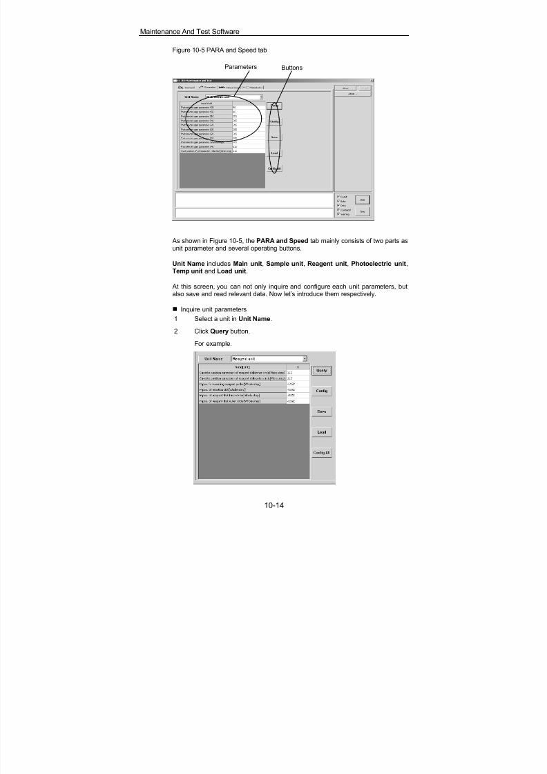
8/20/2019 Mindray BS 300 Analizor Service Manual
http://slidepdf.com/reader/full/mindray-bs-300-analizor-service-manual 96/119
Maintenance And Test Software
10-14
Figure 10-5 PARA and Speed tab
Parameters Buttons
As shown in Figure 10-5, the PARA and Speed tab mainly consists of two parts asunit parameter and several operating buttons.
Unit Name includes Main unit, Sample unit, Reagent unit, Photoelectric unit,Temp unit and Load unit.
At this screen, you can not only inquire and configure each unit parameters, butalso save and read relevant data. Now let’s introduce them respectively.
Inquire unit parameters
1 Select a unit in Unit Name.
2 Click Query button.
For example.
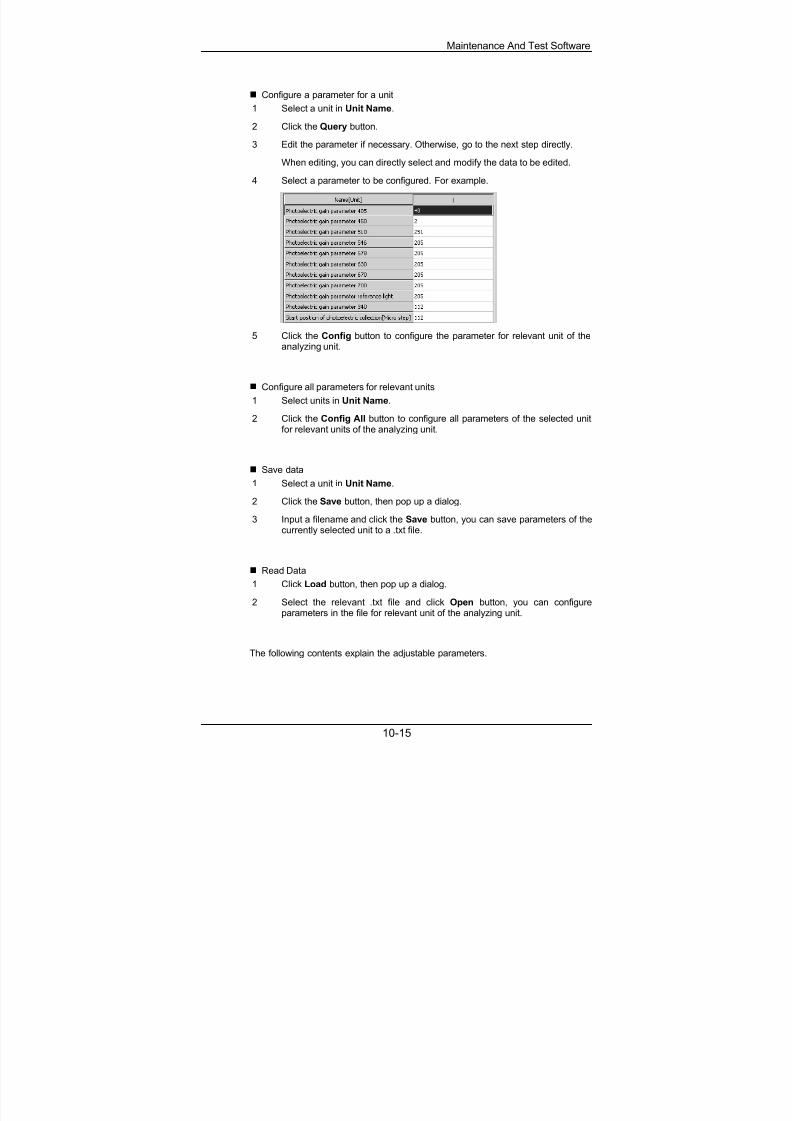
8/20/2019 Mindray BS 300 Analizor Service Manual
http://slidepdf.com/reader/full/mindray-bs-300-analizor-service-manual 97/119
Maintenance And Test Software
10-15
Configure a parameter for a unit
1 Select a unit in Unit Name.
2 Click the Query button.
3 Edit the parameter if necessary. Otherwise, go to the next step directly.
When editing, you can directly select and modify the data to be edited.
4 Select a parameter to be configured. For example.
5 Click the Config button to configure the parameter for relevant unit of theanalyzing unit.
Configure all parameters for relevant units
1 Select units in Unit Name.
2 Click the Config All button to configure all parameters of the selected unitfor relevant units of the analyzing unit.
Save data
1 Select a unit in Unit Name.
2 Click the Save button, then pop up a dialog.
3 Input a filename and click the Save button, you can save parameters of thecurrently selected unit to a .txt file.
Read Data
1 Click Load button, then pop up a dialog.
2 Select the relevant .txt file and click Open button, you can configureparameters in the file for relevant unit of the analyzing unit.
The following contents explain the adjustable parameters.

8/20/2019 Mindray BS 300 Analizor Service Manual
http://slidepdf.com/reader/full/mindray-bs-300-analizor-service-manual 98/119
Maintenance And Test Software
10-16
Reagent unit
Parameter Unit Default What the parameter means
H-pos. for washingreagent probe
Wholestep
42 Position correction of thereagent probe in the horizontaldirection when it is above its
wash well.H-pos. of reaction disk Whole
step-42 Position correction of the
reagent probe in the horizontaldirection when it is above thereaction disk.
H-pos. of reagent diskinner circle
Wholestep
215 Position correction of thereagent probe in the horizontaldirection when it is above theinner circle of reagent disk.
H-pos. of reagent diskouter circle
Wholestep
165 Position correction of thereagent probe in the horizontal
direction when it is above theouter circle of reagent disk.
Position correction ofreagent disk inner circle
Microstep
10 The position correction of thereagent disk when it stops atthe specified position accordingto the position No. of its innercircle.
Position correction ofreagent disk outer circle
Microstep
10 The position correction of thereagent disk when it stops atthe specified position accordingto the position No. of its outercircle.
Sample unit
Parameter Unit Default What the parameter means
Bar code positioncorrection of sampledisk inner circle
Microstep
18 Position correction of the innercircle of sample disk relative tothe outer circle when the barcode scanner scans specifiedpositions.
H-pos. for washing
sample probe
Whole
step
102 Position correction of the
sample probe in the horizontaldirection when it is above itswash well.
H-pos. of sample diskinner circle
Wholestep
202 Position correction of thesample probe in the horizontaldirection when it is above theinner circle of sample disk.
H-pos. of sample diskouter circle
Wholestep
165 Position correction of thesample probe in the horizontaldirection when it is above theouter circle of sample disk.

8/20/2019 Mindray BS 300 Analizor Service Manual
http://slidepdf.com/reader/full/mindray-bs-300-analizor-service-manual 99/119
Maintenance And Test Software
10-17
Parameter Unit Default What the parameter means
H-pos. of sample probein reaction disk
Wholestep
-106 Position correction of thesample probe in the horizontaldirection when it is above thereaction disk.
H-pos. of sample probein ISE
Wholestep
490 Position correction of thesample probe in the horizontaldirection when it is above thesample entry port of ISE unit.
Position correction ofsample disk inner circle
Microstep
10 The position correction of thesample disk when it stops atthe specified position accordingto the position No. of its innercircle.
Position correction ofsample disk outer circle
Microstep
10 The position correction of thesample disk when it stops atthe specified position accordingto the position No. of its outercircle.
V-pos. of sample probein ISE
Wholestep
163 Position correction of thesample probe in the verticaldirection when it is above thesample entry port of ISE unit.
Load unit
Parameter Unit Default What the parameter means
Manipulator h-positionfor placing cuvettes
Wholestep
70 Position correction of themanipulator in horizontaldirection when it places acuvette segment into thereaction disk.
Manipulator h-positionfor taking cuvettes
Wholestep
259 Position correction of themanipulator in horizontaldirection when it takes acuvette segment from thecuvette compartment.
Manipulator v-positionfor placing cuvettes
Wholestep
70 Position correction of themanipulator in vertical directionwhen it places a cuvettesegment into the reaction disk.
Manipulator v-positionfor taking cuvettes
Wholestep
768 Position correction of themanipulator in vertical directionwhen it takes a cuvettesegment from the cuvettecompartment.
Mixing bar h-positionfor washing
Wholestep
68 Position correction of themixing bar in the horizontaldirection when it is above itswash well.

8/20/2019 Mindray BS 300 Analizor Service Manual
http://slidepdf.com/reader/full/mindray-bs-300-analizor-service-manual 100/119
Maintenance And Test Software
10-18
Parameter Unit Default What the parameter means
Mixing bar h-positionfor mixing
Wholestep
70 Position correction of themixing bar in horizontaldirection when it is above thereaction disk.
Photoelectric unit
Parameter Unit Default What the parameter means
Photoelectric gainparameter 405
/ 127 Signal gain coefficient of A/Dconversion for wavelength of405nm.
Photoelectric gainparameter 450
/ 127 Signal gain coefficient of A/Dconversion for wavelength of450nm.
Photoelectric gainparameter 510
/ 127 Signal gain coefficient of A/Dconversion for wavelength of510nm.
Photoelectric gainparameter 546
/ 127 Signal gain coefficient of A/Dconversion for wavelength of546nm.
Photoelectric gainparameter 578
/ 127 Signal gain coefficient of A/Dconversion for wavelength of578nm.
Photoelectric gainparameter 630
/ 127 Signal gain coefficient of A/Dconversion for wavelength of
630nm.Photoelectric gainparameter 670
/ 127 Signal gain coefficient of A/Dconversion for wavelength of670nm.
Photoelectric gainparameter 700
/ 127 Signal gain coefficient of A/Dconversion for wavelength of700nm.
Photoelectric gainparameter referencelight
/ 127 Signal gain coefficient of A/Dconversion for wavelength ofreference light.
Photoelectric gainparameter 340
/ 127 Signal gain coefficient of A/Dconversion for wavelength of340nm.
Start position ofphotoelectric collection
Microstep
25 Correction of the start positionwhen photoelectric collectionstarts.

8/20/2019 Mindray BS 300 Analizor Service Manual
http://slidepdf.com/reader/full/mindray-bs-300-analizor-service-manual 101/119
Maintenance And Test Software
10-19
10.4 Temperature
Figure 10-1 Temperature tab
ReagentTemperature Curve
Control Panel
Reaction Tray
Temperature CurveControl Panel
The Temperature tab consists of two parts:
Curve of reagent preheated temperature (upper part);
Curve of reaction disk (lower part).
The two temperature curves are controlled respectively through two control panelson the right.
Meanings of the parameters on the control panels are as follows.
Parameter What it does
Value Displays current temperature value on the temperaturecurve.
YRange Temperature range on Y-coordinate of the temperaturecurve. Input upper limit and lower limit of temperaturerange in the two boxes.
XRange X-coordinate point of the temperature curve.
Temp Intended temperature expected to achieve.
Period Interval for sampling.
After setting Xrange, Yrange and Temp on the control panel, click Confirm buttonto implement them on relevant temperature curve.
There are 4 more buttons in each of the two control panels:
Start: After setting Period, clicking it, you can start collecting the temperaturedata;

8/20/2019 Mindray BS 300 Analizor Service Manual
http://slidepdf.com/reader/full/mindray-bs-300-analizor-service-manual 102/119
Maintenance And Test Software
10-20
Stop: Clicking it, you can stop collecting the temperature data;
Freeze: Clicking it, you can freeze the displayed curve;
Resume: Clicking it, you can resume the frozen curve.
10.5 Photoelectric
In the Photoelectric tab, the values of photoelectric data and photoelectric datacurve of the selected wavelength are displayed.
Figure 10-2 Photoelectric tab
Display all data
Display curve
Panel
Display maximum data
of each wavelengthDisplay minimum data
of each wavelength
Display difference
between the above two
Through the panel, you can set relevant parameters of photoelectric test data andphotoelectric curve.
Nine wavelengths (340, 405, 450, 510, 546, 578, 630, 670 and 700) and a basewavelength are listed on the control panel. You can select one of them to displayits photoelectric data curve.
Parameter What it does
MinMax Displays maximum and minimum for photoelectric data
of the selected wavelength. YRange Range on the Y-coordinate of the curve. Input upper
limit and lower limit for photoelectric data in the twoboxes.
XRange X-coordinate point of the curve.
CupIndex Specifies the cuvette in certain position of reaction diskto be used to measure photoelectric data.
Dozes-reagent Reagent dispensed to the specified cuvette.
Dozes-sample Sample dispensed to the specified cuvette.
Period Interval for sampling.

8/20/2019 Mindray BS 300 Analizor Service Manual
http://slidepdf.com/reader/full/mindray-bs-300-analizor-service-manual 103/119
Maintenance And Test Software
10-21
Parameter What it does
Times The times of sampling.
Mixer stir Select it to stir the reaction mixture; otherwise thereaction mixture will not be stirred.
Reaction disk rotate Select it to enable the reaction disk to rotate duringmeasurement with photoelectric data of allwavelengths displayed; otherwise the reaction disk willnot be rotated and only photoelectric data of theselected wavelength will be displayed.
Through the control panel, you can select parameters like Wavelength, MinMax, YRange, CupIndex and Period. Moreover, you can select Mixer stir as required.
After setting them, click the Confirm button to confirm the settings.
There are 6 more buttons in the panel:
Start: Clicking it, you can start collecting the temperature data;
Stop: Clicking it, you can stop collecting the temperature data;
Freeze: Clicking it, you can freeze the displayed curve;
Resume: Clicking it, you can resume the frozen curve;
Save: Clicking it, you can save the photoelectric data of all current wavelengthsas a .txt file;
Load: Clicking it, you can read the data in a .txt file saved with photoelectricdata.

8/20/2019 Mindray BS 300 Analizor Service Manual
http://slidepdf.com/reader/full/mindray-bs-300-analizor-service-manual 104/119
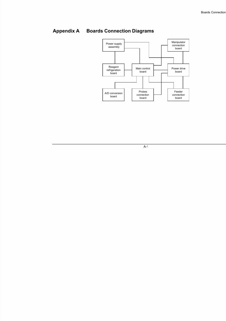
8/20/2019 Mindray BS 300 Analizor Service Manual
http://slidepdf.com/reader/full/mindray-bs-300-analizor-service-manual 105/119
A-1
Appendix A Boards Connection Diagrams
Reagent
refrigeration
board
A/D conversion
board
Manipulator
connection
board
Power drive
board
Main control
board
Feeder
connection
board
Probes
connection
board
Power supply
assembly

8/20/2019 Mindray BS 300 Analizor Service Manual
http://slidepdf.com/reader/full/mindray-bs-300-analizor-service-manual 106/119

8/20/2019 Mindray BS 300 Analizor Service Manual
http://slidepdf.com/reader/full/mindray-bs-300-analizor-service-manual 107/119

8/20/2019 Mindray BS 300 Analizor Service Manual
http://slidepdf.com/reader/full/mindray-bs-300-analizor-service-manual 108/119

8/20/2019 Mindray BS 300 Analizor Service Manual
http://slidepdf.com/reader/full/mindray-bs-300-analizor-service-manual 109/119
A-5
1 21 2 3 J77J731 2 3J74 1 2 3J71 1 2J751 2 3J72 1 2J76 J87
1 2J88 1 2J81 1 2J79 1 2J80 1 2J78 1 2J82 1 2J83 1 2J84 1J85
1
2
3
4
M37-M38: Fans on sides of lamp
housing
2100-20-08114
1 r e d
2 b l u e
G N D
1 2 V
C a b l e
B A 3 0 - 2 0 - 0 6 5 2 5
M42-M43: Refrigeratio
2100-20-06534
G N D
1 2 V
G N D
C a b l e
B A 3 0 - 2 0 - 0 6 5 2 9
M 3 0
- M 3 1 : P E L T I E R
2
1 0 0 - 2 0 - 0 6 6 3 3
1 red
2 black
3 red
4 black
GND
12V
GND
12V
Cable
BA30-20-06535
J89
COOLER
12V
12V
COOLER
M24-M27: Reaction temperature fan
BA30-21-06530
3 r e d
1 y e l l o w
2 b l u e
C a b l e
B A 3 0 - 2 0 - 0 6 5 2 4
1 b l u e
2 r e d
G N D
1 2 V
C35: Reagent refrigeration
temperature transducer
BA30-21-15175
C a b l e
B A 3 0 - 2 0 - 0 6 5 2 3
M
Reagent refrigeration board
BA30-30-06312
C a b l e
B A 3 0 - 2 0 - 0 6 4 8 0
2 b l u e
1
r e d
1 r e d
3 y e l l o w
2 b l u e
G N D
1 2 V
F A N
G N D
1 2 V
F A N
3 r e d
1 y e l l o w
2 b l u e
1 r e d
3 y e l l o w
2 b l u e
G N D
1 2 V
F A N
3 r e d
1 y e l l o w
2 b l u e
1 r e d
3 y e l l o w
2 b l u e
G N D
1 2 V
F A N
3 r e d
1 y e l l o w
2 b l u e
1 r e d
3 y e l l o w
2 b l u e
3 2 1 3 2 1 3 2 1 3 2 1
1 b l u e
2 r e d
1 r e d
2 b l u e
G N D
1 2 V
1 b l u e
2 r e d
2 1 2 1
1 b l u e
2 r e d
1
r e d
2
b l u e
1 b l u e
2 r e d
G N D
1 2 V
2
b l u e
1 b l u e
G N D
1 b l k
1 b l k
Fan on rear side
of lamp housing
2 1
1 r e d
2 b l u e

8/20/2019 Mindray BS 300 Analizor Service Manual
http://slidepdf.com/reader/full/mindray-bs-300-analizor-service-manual 110/119
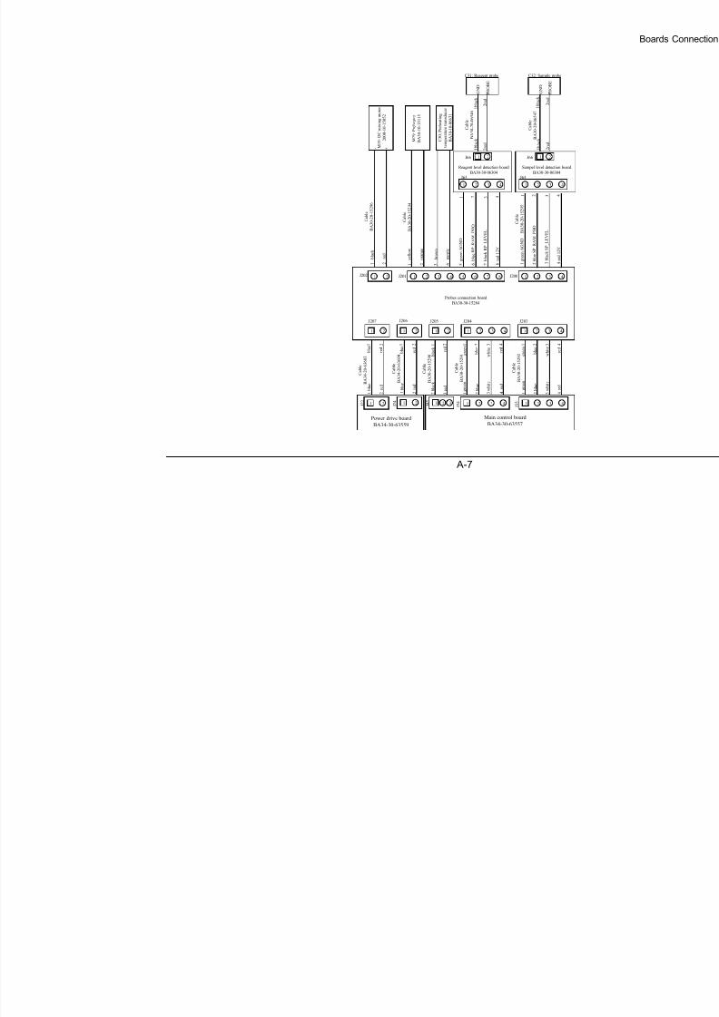
8/20/2019 Mindray BS 300 Analizor Service Manual
http://slidepdf.com/reader/full/mindray-bs-300-analizor-service-manual 111/119
A-7
1 2 3 4 1 2 3 41 21 21 2
2 3 41 6 7 85 2 3 4121 J200J201
J204
J202
J207 J205J206 J203
C a b l e
B A 3 4 - 2 0 - 6 3 6 0 3
2 1
1 2 J 2 2
Power drive board
BA34-30-63559
1 2 J 2 4
2 1
1 2 J 4 5
Main control board
BA34-30-63557
2 1
C a b l e
B A 3 4 - 2 0 - 6 3 6 0 4
C a b l e
B A 3 0 - 2 0 - 1 5 2 9 0
1 2 3 4 J 3 4
2 1 4 3
C a b l e
B A 3 0 - 2 0 - 1 5 2 9 1
1 2 3 4 J 3 5
2 1 4 3
C a b l e
B A 3 0 - 2 0 - 1 5 2 9 2
Probes connection board
BA30-30-15284
C a b l e
B A 3 0 - 2 0 - 1 5 2 9 5
C a b l e
B A 3 0 - 2 0 - 1 5 2 9 6
2 1
b l u e
r e d
b l u e
r e d
b l a c k r e
d
b l u e
g r e e n
w h i t e
r e d
b l u e
g r e e n
w h i t e
r e d
5 g r e e n A G N D
8 r e d 1 2
V
7 b l a c k R P_
L E V E L
6 b l u e R
P_
R A M_
P H O
Sampel level detection board
BA30-30-06304
1 2J66
J65
C32: Sample probe
C a b l e
B A 3 0 - 2 0 - 0 6 5 4 7
P R O B E
G N D
1 g r e e n A G N D
4 r e d 1 2
V
3 b l a c k S P_
L E V E L
2 b l u e S P_
R A M_
P H O
2 3 41
Reagent level detection board
BA30-30-06304
1 2J66
J65
C31: Reagent probe
C a b l e
B A 3 0 - 2 0 - 0 6 5 4 6
P R O B E
G N D
2 3 41
2 1 4 3
2 1
M 2 9 : P r e h
e a t e r
B A 3 0 - 1 0 - 1 5 1 1 5
M 1 9 : D C m i x
i n g m o t o r
2 0 0 0 - 1 0 - 1 5 0 5 2
C 3 0 : P r e h
e a t i n g
t e m p e r a t u r e t r a n s d u c e r
B A 3 0 - 1 0 -
0 6 6 3 1
4 3
2 1 4 3
- +
C a b l e
B A 3 0 - 2 0 - 1 5 2 9 4
1 b l a c k
2 r e d
1 b l a c k
2 r e d
1 b l a c k
2 r e d
1 b l a c k
2 r e d
3
2 b l a c k
3 r e d
2 1 b l u e
r e d
b l u e
r e d
2 1 b l u e
g r e e n
w h i t e
r e d
2 1 4 3 2 1 4 3 b l u e
g r e e n
w h i t e
r e d
r e d
b l a c k
p u r p l e
y e l l o w
o r a n g e
b r o w n

8/20/2019 Mindray BS 300 Analizor Service Manual
http://slidepdf.com/reader/full/mindray-bs-300-analizor-service-manual 112/119
A-8
2
J103
1
4
3
2
J108
1
4
3
2
J102
1
4
3
2
J101
1
4
3
VCC
GND
GND
MAGD_PHO
VCC
GND
GND
VCC
VCC
GND
GND
GND
GND
MAGU_PHO
LOADY_PHO
LOADX_PHO
2
J107
1
9
5 6
3 4
7 8
3 white
1 black
2 blue
4 red
3 white
1 black
2 blue
4 red
3 white
1 green
2 black
4 red
3 white
1 green
2 black
4 red
1 blue
Cable
BA33-21-3
Cable
BA33-20-351
Power drive board
BA34-30-63559
Manipulator connection boardBA30-30-06316
2
J43
1
9
5 6
3 4
7 8
1
10
9
87
65
43
2
1
10
9
87
65
43
2
Main control board
BA34-30-63557
URAM_PHO
LOADX_PHODRAM_PHO
LOADY_PHO
VCCMAGU_PHO
MAGD_PHO
GND
GNDGND
2J109
14 3
G N D
G N D
2J110
14 3
G N D
G N D
2
J106
1
4
3
MAGU+
M A G U -
M A G U +
2 12 1 J105J104
M A G D -
M A G D +
2 red
1 blue
2 red
MAGU-
MAGD+
MAGD-
2 yellow
4 red
3 blue
1 white
URAM_PHO
LOADX_PHO
DRAM_PHO
LOADY_PHO
VCCMAGU_PHO
MAGD_PHO
GND
GNDGND
2
J3
1
4
3
MAGU+
MAGU-
MAGD+
MAGD-
Cable
BA30-20-06463
10
D R A M_
P H O
U R A M_
P H O
Cable
BA33-21-35
Cable
BA33-21-35
Cable
BA33-21-35
Cable
BA33-20-35
Cable
BA30-20-06486
2 yellow
4 red
3 blue
1 white
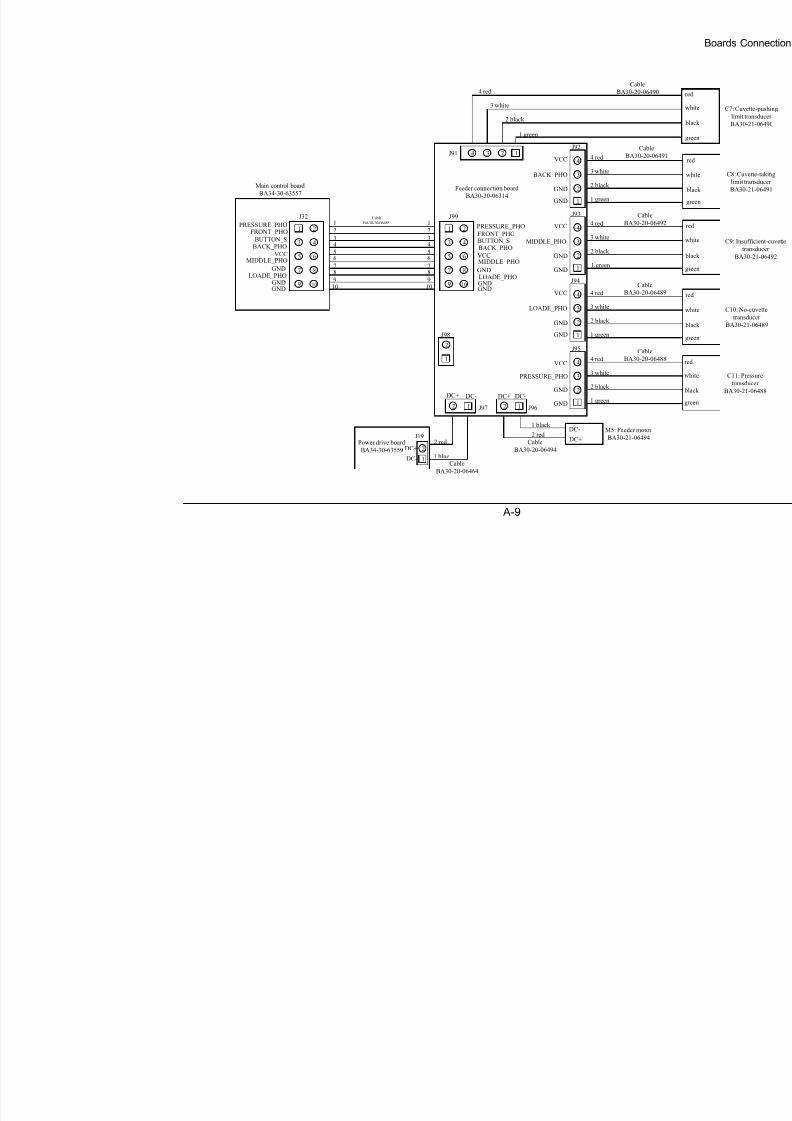
8/20/2019 Mindray BS 300 Analizor Service Manual
http://slidepdf.com/reader/full/mindray-bs-300-analizor-service-manual 113/119
A-9
2 J96
DC-DC+
12 J97
DC-DC+
1
2J91 14 3
2
J95
1
4
3
2
J94
1
4
3
2
J93
1
4
3
2
J92
1
4
3
VCC
GND
GND
PRESSURE_PHO
VCC
GND
GND
VCC
VCC
GND
GND
GND
GND
LOADE_PHO
MIDDLE_PHO
BACK_PHO
2
J99
1
9
5 6
3 4
7 8
2
1
3 white
1 green
2 black
4 red
3 white
1 green
2 black
4 red
3 white
1 green
2 black
4 red
3 white
1 green
2 black
4 red
3 white
1 green
2 black
4 red
J98
1 black
2 redDC+
DC- M5: Feeder motor
BA30-21-06494
Cable
BA30-20-06490
Cable
BA30-20-06491
Cable
BA30-20-06492
Cable
BA30-20-06489
Cable
BA30-20-06488
Cable
BA30-20-06494Power drive board
BA34-30-63559
DC-
DC+ 2
1
J19
1 blue
2 red
Cable
BA30-20-06464
Feeder connection board
BA30-30-06314
2
J32
1
9
5 6
3 4
7 8
1
109
87
65
43
2
1
109
87
65
43
2
Main control board
BA34-30-63557
PRESSURE_PHOFRONT_PHO
BUTTON_SBACK_PHO
VCCMIDDLE_PHO
LOADE_PHO
GND
GNDGND
PRESSURE_PHO
FRONT_PHOBUTTON_SBACK_PHO
VCCMIDDLE_PHO
LOADE_PHO
GND
GNDGND1010
Cable
BA30-20-06485

8/20/2019 Mindray BS 300 Analizor Service Manual
http://slidepdf.com/reader/full/mindray-bs-300-analizor-service-manual 114/119

8/20/2019 Mindray BS 300 Analizor Service Manual
http://slidepdf.com/reader/full/mindray-bs-300-analizor-service-manual 115/119
Test Points of Boards
B-1
Appendix B Test Points of Boards
B.1 Test Points on A/D Conversion BoardTP TOP/BOTTOM Descriptions
TP1 TOP The signal at 340nm
TP2 TOP The signal at 405nm
TP3 TOP The signal at 450nm
TP4 TOP The signal at 510nm
TP5 TOP The signal at 546nm
TP6 TOP The signal at 578nm
TP7 TOP The signal at 630nm
TP8 TOP The signal at 670nm
TP9 TOP The signal at 700nm
TP10 TOP The signal of REF
TP11 TOP The start signals of AD conversion
TP12 TOP GND
TP13 TOP The input analog signals of AD conversion
B.2 Test Points on Drive Board
TP TOP/BOTTOM Descriptions
TP1 TOP Signal ground (SHIELD) from the main control board
TP2 TOP 5V and 24V ground (GND)
TP3 TOP 5V and 24V ground (GND)
TP4 TOP 12V ground (12VGND)
B.3 Test Points on Reagent Refrigeration Board
TP TOP/BOTTOM DescriptionsTP1 TOP The temperature switch signal (low)
TP2 TOP The temperature switch signal (high)
TP3 TOP Reference ground
TP4 TOP The switch characteristic of Q1
TP5 TOP The voltage of the temperature transducer
B.4 Test Points on Main Control Board
TP TOP/BOTTOM DescriptionsTP1 BOTTOM&TOP TxD of Sample Unit

8/20/2019 Mindray BS 300 Analizor Service Manual
http://slidepdf.com/reader/full/mindray-bs-300-analizor-service-manual 116/119
Test Points of Boards
B-2
TP TOP/BOTTOM Descriptions
TP2 BOTTOM&TOP RxD of Sample Unit
TP3 BOTTOM&TOP ALE of Sample Unit
TP4 BOTTOM&TOP TxD of photoelectric unit
TP5 BOTTOM&TOP RxD of photoelectric unitTP6 BOTTOM&TOP ALE of photoelectric unit
TP7 BOTTOM&TOP INT of SPI port
TP8 BOTTOM&TOP RxD of Main unit
TP9 BOTTOM&TOP TxD of Main unit
TP10 BOTTOM&TOP ALE of Main unit
TP11 BOTTOM&TOP Clock Output of Crystal 16MHZ
TP12 BOTTOM&TOP TxD of loading/mixing unit
TP13 BOTTOM&TOP RxD of loading/mixing unit
TP14 BOTTOM&TOP ALE of loading/mixing unit
TP15 BOTTOM&TOP GND
TP16 BOTTOM&TOP VDD 3.3V power
TP17 BOTTOM&TOP VEE 1.5V power
TP18 BOTTOM&TOP VTTP +15V power
TP19 BOTTOM&TOP VTTN -15V power
TP20 BOTTOM&TOP GNDTT GND of ±15V
TP21 BOTTOM&TOP VCC 5V Power
TP22 BOTTOM&TOP VPP 12V powerTP23 BOTTOM&TOP VCCA analog power of 5V
TP24 BOTTOM&TOP AGND analog GND of 5V
TP25 BOTTOM&TOP GND
TP26 BOTTOM&TOP RxD of Sample Unit Extended COM for Bar Code Scanner
TP27 BOTTOM&TOP TxD of Sample Unit Extended COM for Bar Code Scanner
TP28 BOTTOM&TOP TxD of Reagent Unit Extended COM for Bar Code Scanner
TP29 BOTTOM&TOP RxD of Main Unit Extended COM for ISE module
TP30 BOTTOM&TOP RxD of Reagent Unit Extended COM for Bar Code Scanner
TP31 BOTTOM&TOP TxD of Main Unit Extended COM for ISE module
TP32 BOTTOM&TOP Clock Output of Crystal 10MHZ
TP33 BOTTOM&TOP ALE of temperature unit
TP34 BOTTOM&TOP TxD of temperature unit
TP35 BOTTOM&TOP RxD of temperature unit
TP36 BOTTOM&TOP RxD of Reagent unit
TP37 BOTTOM&TOP TxD of Reagent unit
TP38 BOTTOM&TOP ALE of Reagent unit

8/20/2019 Mindray BS 300 Analizor Service Manual
http://slidepdf.com/reader/full/mindray-bs-300-analizor-service-manual 117/119
Test Points of Boards
B-3
B.5 Test Points on PFC Board
TP TOP/BOTTOM Descriptions
TP1 BOTTOM The switch waveforms of Q3 and Q4
TP2 BOTTOM The drive waveform of Q5
TP3 BOTTOM The DC output (390V)
TP4 BOTTOM The reference voltage of U2 (7.5V)
TP5 BOTTOM The oscillation waveform of U2 (100KHz)
TP6 BOTTOM The Vss supply (19V)
TP7 BOTTOM The VDD supply (14V)
TP8 BOTTOM The VPP supply (12V)
TP9 BOTTOM The drive waveform of Q12 (85KHz)
TP10 BOTTOM The switch waveform of Q12
TP11 BOTTOM The current waveform of Q12
TP12 BOTTOM The reference voltage of U8 (5V)
TP13 BOTTOM The oscillation waveform of U8
TP14 BOTTOM The 12V(4.5A) supply
B.6 Test Points on 5V/12V Board
TP TOP/BOTTOM Descriptions
TP1 BOTTOM The DC output (390V)
TP2 BOTTOM Input side as reference ground
TP3 BOTTOM The VDD supply (14V)
TP4 BOTTOM The oscillation waveform of U301 (100KHz)
TP5 BOTTOM The reference voltage of U301 (5V)
TP6 BOTTOM The switch drive waveform
TP7 BOTTOM The switch waveform
TP8 BOTTOM The 12V(10A) output
TP9 BOTTOM The output control voltage of the board
TP10 BOTTOM The 12V(4.7A) output
TP11 BOTTOM The supply of FAN (12V)
TP12 BOTTOM The 5V output of the board
TP13 BOTTOM Output side as reference ground
TP14 BOTTOM The switch waveform of U355 (72KHz)
TP15 BOTTOM Short circuit with the output side reference ground andmeasure the OVP point of the two 12Vs
TP16 BOTTOM Short circuit with the output side reference ground andmeasure the OVP point of the two 5V
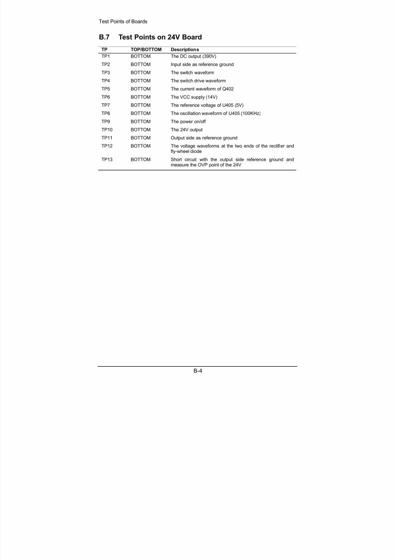
8/20/2019 Mindray BS 300 Analizor Service Manual
http://slidepdf.com/reader/full/mindray-bs-300-analizor-service-manual 118/119
Test Points of Boards
B-4
B.7 Test Points on 24V Board
TP TOP/BOTTOM Descriptions
TP1 BOTTOM The DC output (390V)
TP2 BOTTOM Input side as reference ground
TP3 BOTTOM The switch waveform
TP4 BOTTOM The switch drive waveform
TP5 BOTTOM The current waveform of Q402
TP6 BOTTOM The VCC supply (14V)
TP7 BOTTOM The reference voltage of U405 (5V)
TP8 BOTTOM The oscillation waveform of U405 (100KHz)
TP9 BOTTOM The power on/off
TP10 BOTTOM The 24V output
TP11 BOTTOM Output side as reference ground
TP12 BOTTOM The voltage waveforms at the two ends of the rectifier andfly-wheel diode
TP13 BOTTOM Short circuit with the output side reference ground andmeasure the OVP point of the 24V

8/20/2019 Mindray BS 300 Analizor Service Manual
http://slidepdf.com/reader/full/mindray-bs-300-analizor-service-manual 119/119


