
MIMO Radar -- Diversity Means Superiority - MIT Lincoln · PDF file ·...
33
SAL, Dept. of ECE 1 MIMO Radar -- Diversity Means Superiority Jian Li Department of Electrical and Computer Engineering University of Florida Gainesville, Florida, USA Petre Stoica Department of Information Technology, Uppsala University, Uppsala, Sweden Collaborators: William Roberts, Yao Xie, Luzhou Xu
Transcript of MIMO Radar -- Diversity Means Superiority - MIT Lincoln · PDF file ·...

SAL, Dept. of ECE 1
MIMO Radar-- Diversity Means Superiority
Jian Li
Department of Electrical and Computer Engineering University of Florida
Gainesville, Florida, USA
Petre Stoica
Department of Information Technology,
Uppsala University,Uppsala, Sweden
Collaborators: William Roberts, Yao Xie, Luzhou Xu

SAL, Dept. of ECE 2
Outline
IntroductionParameter Identifiability
Generic sufficient conditionsCramer-Rao boundsLeast-squares estimator
Adaptive MIMO TechniquesCaponGeneralized Likelihood Ratio Test
Flexible Transmit Beampattern DesignsBeampattern matching DesignMinimum Sidelobe Beampattern DesignComparison with Phased-Array CounterpartApplications
Summary

SAL, Dept. of ECE 3
Introduction
MIMO RadarMultiple DifferentTransmitted Waveforms
Either correlated or uncorrelated
Phased-Array RadarSingle Waveform Scaled and
TransmittedCan be MIMOSpecial Case:
SIMO: Single-Input Multiple-Output

SAL, Dept. of ECE 4
Outline
IntroductionParameter Identifiability
Generic sufficient conditionsCramer-Rao boundsLeast-squares estimator
Adaptive MIMO TechniquesCaponGeneralized Likelihood Ratio Test
Flexible Transmit Beampattern DesignsBeampattern matching DesignMinimum Sidelobe Beampattern DesignComparison with Phased-Array CounterpartApplications
Summary

SAL, Dept. of ECE 5
Generic Sufficient Conditions
Parameter Identifiability: Maximum number of targets that can be uniquely identified
High SNRLarge Snapshot Number
Phased-Array:
MIMO Radar:
Depending on array geometry and the number of shared antennas between transmit and receive arrays.

SAL, Dept. of ECE 6
Superior Parameter Identifiability
The maximum number of targets that can be uniquely identified by a MIMO radar is up to times of its phased-array counterpart.
= Transmit Antenna Number

SAL, Dept. of ECE 7
Example 1
: Receiving antenna.
: Transmitting antenna,
1 2 3 4 5 6 7 8 9 10
ULAHalf-wavelength spacingOmnidirectional probing (orthogonal waveforms)
SAL, Dept. of ECE 8
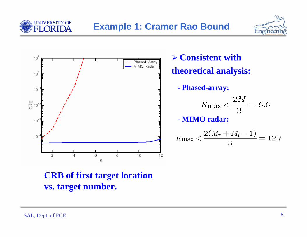
Example 1: Cramer Rao Bound
Consistent with theoretical analysis:
- Phased-array:
- MIMO radar:
CRB of first target location vs. target number.

SAL, Dept. of ECE 9
Example 1: LS Estimator
All 12 target locations can be approximately determined from peak locations.

SAL, Dept. of ECE 10
Example 2
Receiving ULA: 0.5-wavelength spacing
Transmitting ULA: 2.5-wavelenth spacing
Orthogonal waveforms
: Receiving antenna.: Transmitting antenna,
1 2 3 8 94 5 6 7

SAL, Dept. of ECE 11
Example 2: Cramer-Rao Bound
CRB of first target location vs. target number.
Consistent with theoretical analysis:
- Phased-array:
- MIMO radar:

SAL, Dept. of ECE 12
Example 2: Least Squares Estimator
All 16 target locations can be approximately determined from peak locations.

SAL, Dept. of ECE 13
Outline
IntroductionParameter Identifiability
Generic sufficient conditionsCramer-Rao boundsLeast-squares estimator
Adaptive MIMO TechniquesCaponGeneralized Likelihood Ratio Test
Flexible Transmit Beampattern DesignsBeampattern matching DesignMinimum Sidelobe Beampattern DesignComparison with Phased-Array CounterpartApplications
Summary

SAL, Dept. of ECE 14
Adaptive MIMO Radar MIMO Radar
Different Targets Reflect Different WaveformsAdaptive techniques directly applicable
Phased-ArrayDifferent Targets Reflect Identical WaveformAdaptive Techniques Not Directly Applicable
= covariance matrix of reflected waveforms

SAL, Dept. of ECE 15
Example 3
: Receiving antenna.
: Transmitting antenna,
1 2 3 4 5 6 7 8 9 10
Three Targets at -40, 0, 40 degreesOne Strong Jammer at 25 degreesJammer Waveform Uncorrelated with Radar Transmitted WaveformsUncorrelated Radar Transmitted Waveforms
Omnidirectional ProbingULA
Half-wavelength spacing

SAL, Dept. of ECE 16
Example 3: Capon and GLRT
−50 0 500
0.5
1
1.5
2
Cap
on
Sp
ectr
um
Angle (degree)−50 0 50
0
0.5
1
1.5
2
GL
RT
Angle (degree)
Capon Spatial Spectrum GLRT Pseudo-Spectrum
No false peak

SAL, Dept. of ECE 17
Outline
IntroductionParameter Identifiability
Generic sufficient conditionsCramer-Rao boundsLeast-squares estimator
Adaptive MIMO TechniquesCaponGeneralized Likelihood Ratio Test
Flexible Transmit Beampattern DesignsBeampattern matching DesignMinimum Sidelobe Beampattern DesignComparison with Phased-Array CounterpartApplications
Summary

SAL, Dept. of ECE 18
Transmit Beampattern
Covariance Matrix of Transmitted Waveforms
Transmit Beampattern
Uniform Elemental Power Constraint

SAL, Dept. of ECE 19
Beampattern Matching Design
Design GoalsMinimize difference between
synthesized and desired beampatternsMinimize cross-correlations
among target reflected waveformsConstraint
Total power or(Equal) elemental power
Can be formulated as Semi-definite Quadratic Program (SQP)
−50 0 500
0.5
1
1.5
Angle (degree)
Bea
mp
atte
rn
−50 0 500
0.5
1
1.5
2
2.5
3
Angle (degree)
Bea
mp
atte
rn

SAL, Dept. of ECE 20
Several Examples
•M=10•Equal Elemental Power•Total Power = 1•ULA•Half-wavelength spacing -80 -60 -40 -20 0 20 40 60 800
0.5
1
1.5
2
2.5
3
Angle (degree)
Bea
mpa
ttern
-80 -60 -40 -20 0 20 40 60 800
0.5
1
1.5
2
2.5
3
3.5
4
4.5
Angle (degree)
Bea
mpa
ttern
-80 -60 -40 -20 0 20 40 60 800
0.5
1
1.5
2
2.5
3
3.5
4
4.5
DOA (Degree)
Mag
nitu
de o
f Bea
mpa
ttern

SAL, Dept. of ECE 21
Example 3: Further Probing
Blockdiagram
Optimal Probing
Initial probing
Initial Omnidirectional
Probing
GLRT
Angle/Amplitude Estimation
Capon
BeampatternMatching
AML CaponEnhanced Angle/Amplitude Estimation

SAL, Dept. of ECE 22
Example 3: MSE Improvement
Angle MSE vs. Reciprocal of Noise Power
10+ dB 10+ dB
Amplitude MSE vs. Reciprocal of Noise Power
•M=10, ULA, Half-wavelength spacing•Equal Elemental Power, Total Power = 1•Targets at -40, 0, 40 degrees; Jammer at 25 degrees

SAL, Dept. of ECE 23
Example 3: Resolution
Targets now at -40, 0, 3 degrees Omnidirectional Beampattern Matching
Capon
GLRT
-80 -60 -40 -20 0 20 40 60 800
0.5
1
1.5
Cap
on S
pect
rum
Angle (degree) -80 -60 -40 -20 0 20 40 60 800
0.5
1
1.5
Cap
on S
pect
rum
Angle (degree)
-80 -60 -40 -20 0 20 40 60 800
0.5
1
1.5
GLR
T
Angle (degree)-80 -60 -40 -20 0 20 40 60 80
0
0.5
1
1.5
GLR
TAngle (degree)
SAL, Dept. of ECE 24
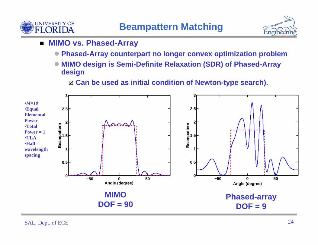
Beampattern MatchingMIMO vs. Phased-Array
Phased-Array counterpart no longer convex optimization problemMIMO design is Semi-Definite Relaxation (SDR) of Phased-Array design
Can be used as initial condition of Newton-type search).
Phased-arrayDOF = 9
MIMO DOF = 90
−50 0 500
0.5
1
1.5
2
2.5
3
Angle (degree)
Bea
mp
atte
rn
−50 0 500
0.5
1
1.5
2
2.5
3
Angle (degree)B
eam
pat
tern
•M=10•Equal Elemental Power•Total Power = 1•ULA•Half-wavelength spacing

SAL, Dept. of ECE 25
Minimum Sidelobe BeampatternDesign
Design GoalMinimize peak sidelobe levelAchieve prescribed 3 dB main-
beam widthSubject to either total power or (equal) elemental power constraint
Can be formulated as Semi-Definite Program (SDP)
MIMO Design is SDR of Phased-Array Design
MIMO design is used as initial condition for Newton-type search to obtain phased-array design

SAL, Dept. of ECE 26
Minimum Sidelobe Design Example
M=10 (uniform elemental power constraint, 0.1 per element)Mainbeam pointing at3 dB Mainbeam width = 20 degreesSidelobe regionULA, Half-wavelength spacing
0 0θ =
MIMO Phased-array
−50 0 50−30
−20
−10
0
10
20
Angle (degree)
Bea
mp
atte
rn (
dB
)
−50 0 50−30
−20
−10
0
10
20
Angle (degree)
Bea
mp
atte
rn (
dB
)
90 , 20 20 ,90⎡ ⎤ ⎡ ⎤− − ∪⎣ ⎦ ⎣ ⎦

SAL, Dept. of ECE 27
Minimum Sidelobe Design Example
Relaxed Elemental Power ConstraintWithin 20% of 0.1 for each elemental powerTotal transmitted power = 1
−50 0 50−30
−20
−10
0
10
20
Angle (degree)
Bea
mp
atte
rn (
dB
)
−50 0 50−30
−20
−10
0
10
20
Angle (degree)B
eam
pat
tern
(d
B)
MIMO Phased-array

SAL, Dept. of ECE 28
Applications
Directed Energy System for Homeland Defense
All antennas transmit at their maximum powerLarge apertureSufficient mainbeamwidth since target is movingNo impact on friendly targets

SAL, Dept. of ECE 29
Thermal Therapy
Thermal Therapy System in Medicine
Ultrasound has good penetrationAll transducers transmit at a low power to avoid harming healthy tissueLarge aperture needed to deliver sufficient energySufficient mainbeam width needed

SAL, Dept. of ECE 30
Drowning in Sound
“It’s clear that the ocean is under siege from a lot of different sources.”
[1] Jean Kumagai, “Drowning in Sound,” IEEE Spectrum, April 2006.
Whale stranded during a military sonar exercise near Canary Islands in July 2004 [1]

SAL, Dept. of ECE 31
Reduce Ocean Noise
Distributed Sensor Network?Large Aperture to Deliver Sufficient Energy At Focal PointLow Power Transmitted by Each SensorWaveform Diversity to Achieve Desired Mainbeam Width
Currently, 220 dB pulses generated by active sonar and air-gun arrays [1]

SAL, Dept. of ECE 32
Outline
IntroductionParameter Identifiability
Generic sufficient conditionsCramer-Rao boundsLeast-squares estimator
Adaptive MIMO TechniquesCaponGeneralized Likelihood Ratio Test
Flexible Transmit Beampattern DesignsBeampattern matching DesignMinimum Sidelobe Beampattern DesignComparison with Phased-Array CounterpartApplications
Summary

SAL, Dept. of ECE 33
Summary
Waveform Diversity Offered by MIMO Radar Enables Significant Superiority Over Its Phased-Array Counterpart
Parameter IdentifiabilityDirect Applicability of Adaptive TechniquesFlexible Transmit Beampattern Designs
MIMO Applications are DiverseDefenseMedicine
Probing FurtherMany fundamental issues need to be addressed on MIMO Your thoughts?