MILLSTONE RIVER FISH BYPASS CHANNEL DESIGN...
25
MILLSTONE RIVER FISH BYPASS CHANNEL DESIGN AND CONSTRUCTION SUMMARY Prepared for: Fisheries and Oceans Canada 4166B Departure Bay Road Nanaimo BC V9T 6G5 Prepared by: Northwest Hydraulic Consultants #202-3150 Island Highway North Nanaimo BC V9T 4B7 Project no. 34687 December 2008
Transcript of MILLSTONE RIVER FISH BYPASS CHANNEL DESIGN...

MILLSTONE RIVER
FISH BYPASS CHANNEL
DESIGN AND CONSTRUCTION SUMMARY
Prepared for: Fisheries and Oceans Canada
4166B Departure Bay Road Nanaimo BC V9T 6G5
Prepared by: Northwest Hydraulic Consultants
#202-3150 Island Highway North Nanaimo BC V9T 4B7
Project no. 34687
December 2008

Millstone River Fish Bypass Channel Design and Construction Summary i
Table of Contents Table of Contents ............................................................................................................... i List of Tables ..................................................................................................................... ii List of Photos ..................................................................................................................... ii List of Appendices............................................................................................................. ii 1.0 Design Overview.....................................................................................................1 2.0 Hydraulic Design of the Intake and Diversion....................................................3 3.0 Construction ...........................................................................................................4
3.1 May – June 10.....................................................................................................4 3.2 June 10 – 16 ........................................................................................................4 3.3 June 17 – 23 ........................................................................................................4 3.4 July 1 – 7 .............................................................................................................4 3.5 July 8 – 14 ...........................................................................................................5 3.6 July 15 –21 ..........................................................................................................5 3.7 July 22 – 28 .........................................................................................................6 3.8 July 29 – August 4 ..............................................................................................6 3.9 August 5 – August 11 .........................................................................................6 3.10 August 12 – August 18 .......................................................................................6 3.11 August 19 – August 25 .......................................................................................7 3.12 August 26 – Sept 1..............................................................................................7 3.13 Sept 2 – Sept 8 ....................................................................................................7 3.14 Sept 9 – Sept 15 ..................................................................................................8 3.15 Sept 16 – Sept 22 ................................................................................................8 3.16 Sept 23 – Oct.......................................................................................................8
4.0 Costs ........................................................................................................................9

Millstone River Fish Bypass Channel Design and Construction Summary ii
List of Tables Table 1. Intake flows........................................................................................................... 2
Table 2. Diversion flows..................................................................................................... 2
Table 3. List of Contractors ................................................................................................ 3
List of Photos Photo 1. Millstone Parkway closed during construction. ....................................................5
Photo 2. The channel alignment was cleared and a trench was excavated to drain moisture out of the site..........................................................................................5
Photo 3. Topsoil was removed down to bedrock along the channel alignment...................6
Photo 4. Trucks were used intermittently to haul materials.................................................6
Photo 5. An excavator with a breaker attachment formed the channel into the bedrock..................................................................................................................7
Photo 6. A rock drill blasted the channel from Stn 0+00 to 0+60. ......................................7
Photo 7. The old fishway was modified and the new channel was connected to the Millstone River at the base of Millstone Falls. .....................................................8
Photo 8. The diversion structure footing was poured first, followed by the walls. .............8
Photo 9. The outer edges of the intake walls were poured against the bedrock. .................9
Photo 10. A 130 mm diameter pipe and a valve were installed between the upper and lower duck ponds to help flush the lower pond. .........................................9
Photo 11. A trash rack was attached to the concrete spillway/diversion wall to keep debris out of the diversion structure.................................................................10
Photo 12. A trash rack and walkway grating were affixed to the intake. A handrail was also installed (not shown in photo)...........................................................10
Photo 13. The pond at Stn 1+60 was filled with LWD to provide fish habitat. ................11
Photo 14. A typical 200 – 300 mm drop structure with LWD in the pool.........................11
List of Appendices Appendix A: As-Built Drawings Appendix B: Financial Summary
Millstone River Fish Bypass Channel Design and Construction Summary 1
1.0 Design Overview A bypass channel was constructed to help migrating Coho salmon navigate around several barriers in the Millstone River. The bypass channel concept was chosen over a series of traditional fish ladders because it had less impact on the river (function and aesthetics), was less expensive, could provide spawning and rearing opportunities, and could serve as a community education platform. The channel was constructed on the left bank of the Millstone River in Bowen Park. The area was extensively surveyed from the Lenhart foot bridge down to Millstone Falls in several stages from 1998 to 2005. After numerous design iterations the channel alignment was flagged in May and the main construction phase took place from June to October, 2007. In total, 857 m of new channel and pool fish habitat was constructed. The channel was designed such that:
• the grade would be 0 - 4%, and maximum of 6.5%, • the impact to trees and park vegetation would be minimized as much as possible, • fish rearing/resting pools and spawning areas could be incorporated, • channel flood damage/risk from the Millstone River would be reduced, and • the upper and lower connection points to the river would allow fish passage.
At the upstream end (Stn 0+00) the channel flow is diverted from the Millstone River through the concrete intake structure. The purpose of the structure is to restrict flood flows into the bypass channel so that erosion and sedimentation is limited. Also, adult migrating salmon must swim upstream through the intake at various river stages. For low summer flow conditions the intake is designed to divert no more than 10% of the Millstone River; the intake is fully adjustable through orifice plate and weir modifications (Section 2.0) The channel was blasted from Stn 0+00 to 0+60, and a sediment settling pond and diversion structure are located at Stn 0+60. The purpose of the diversion structure is to trim extreme flood flows (>10-year) away from the bypass channel. (Section 2.0) From Stn 0+90 to 8+57 the channel is a series of step pools, ponds, and boulder riffles. The step pools are generally 3 to 5 m long and have a 0.2 to 0.3 m drop. Significant ponds are located at Stn 1+60, 2+55, 3+10, 4+05, 4+85, 5+75, and 7+50. The pond depths vary, and have a maximum depth of approximately 1 to 1.5 m. A spawning area was provided from Stn 2+80 to 3+00. Boulder riffles assist upstream migration at Stn 3+10 to 3+25 and Stn 8+25 to 8+50. The channel flows through 10 m long by 1000 mm diameter culverts under the Millstone Parkway at Stn 5+15 to 5+25 and the parking area at Stn 6+80 to 6+90. The culverts are installed at 0% grade and are backwatered approximately 0.4 m.

Millstone River Fish Bypass Channel Design and Construction Summary 2
Near the outlet the channel connects with the old fishway structure at Stn 8+50. The old fishway structure was modified to prevent upstream fish migration, but the additional flow helps attract fish to the bypass channel outlet at the base of the falls. Large Woody Debris (LWD) was placed in the channel and ponds to provided approximately 20% coverage. Small spawning gravel platforms were constructed throughout the project. The Bowen Park trail system was modified to incorporate viewing and walking areas near the channel. Three new footbridges were constructed over the channel at Stn: 4+50, 5+90, and 7+75. The lower duck pond was hydraulically connected to channel with a 130 mm diameter, valved pipe. The purpose of the pipe is to increase circulation, and thus water quality, in the lower pond. Overall, the water level drop between the bypass channel intake and outlet is 27.3 m and the average gradient is 3.2%.

Millstone River Fish Bypass Channel Design and Construction Summary 3
2.0 Hydraulic Design of the Intake and Diversion The bypass channel intake is designed to maintain a measured wetted flow at all times of the year. During periods of low flow in the mainstem, the intake diverts approximately 10% of Millstone River into the bypass channel. During periods of high flow, the intake regulates channel flows to prevent flood damage, erosion and overtopping. The estimated maximum flow to the bypass channel is 300 L/s. Flows higher than this may cause erosion damage, allow water to escape the channel, and impede fish migration. During extreme flood events, the intake will be inundated and will become ineffective at limiting the flows to the channel. The reason the intake is designed to flood is because a larger/higher intake would restrict flow too much in the river and potentially increase flooding issues on Riverside Drive. The as-built intake has negligible effects on flood levels in the river. The diversion structure is located 60 m downstream of the intake. The diversion structure is designed to trim the flood flows, diverting most of the flood water over a spillway and back to the river. The event return period when the diversion is activated has not been formally calculated. However, qualitative evidence of flooding on Riverside Road adjacent to the intake indicates an approximate return period on the order of 10-years or greater. The intake structure features four baffles with 250 x 600 mm submerged orifices. A control weir is located at the downstream end of the structure. The weir is set at the same elevation as the natural creek invert (solid rock). Typical water levels in the river are estimated to be El. 49.8 m; design flows for the channel are 120 L/s (Table 1). The downstream control weir is a compound V-shape. The compound V-shape regulates low flows to approximately 10% diversion from the mainstem. The diversion structure consists of a spillway and a flow control structure. The spillway invert elevation is set at El. 48.36 m and the length is 9.7 m long. The flow control structure features three baffles and three weirs. Similar to the intake, the baffles have 250 x 600 mm submerged orifices. The upstream-most weir provides tailwater control for the orifices. The weir crests are angled towards the left wall to concentrate flows and aid fish migration. Each weir has a 300 mm drop. The upstream-most weir has elevation of 47.54 m. The middle weir El. 47.84 and lower weir El. 48.14 m. The first rock riffle at the outlet of the structure is at elevation 47.2 m (approximately).

Millstone River Fish Bypass Channel Design and Construction Summary 4
3.0 Construction During the construction phase of the project the Millstone Parkway was closed to vehicle traffic and volunteer teams answered questions from the public about the project, directed foot and bicycle traffic around the construction zone, and provided site security during daylight hours (Photo 1). A professional security firm was contracted for site security during nighttime hours. From July to September a fire truck with a large tank was kept on site to mitigate the risk of a serious fire potentially started by the construction work. In general, the channel was constructed with a three stage approach. The first stage saw the removal of the vegetation and overburden (soil) down to the bedrock. For the second stage a channel was chipped into the bedrock, and the third stage required careful placement of wood, riprap, and gravel in the channel to create fish habitat features. Many local contractors were used to construct the project (Table 3).
3.1 May – June 10 Approximately 150 second growth fir tree stumps with stem diameters of approximately 0.3 to 0.5 m were imported and stockpiled in the parking area near the duck pond. The stumps were used as Large Woody Debris (LWD) features in the channel Approximately 500 native plants were salvaged by digging the plants up by hand, placing them in buckets, and storing off-site.
3.2 June 10 – 16 Potential danger trees on the worksite were assessed by a certified arbourist; approximately three dozen trees along the proposed side channel alignment were classified hazardous to worker safety. In accordance with Work Safe BC regulations, the hazardous trees were felled and bucked to approximately 10 meter lengths to allow for handling.
3.3 June 17 – 23 Preliminary earthwork included excavating a 1 m wide drainage trench with a Komatsu PC200-6 excavator (Komatsu 200) along approximately 500 m of channel length (Photo 2). The purpose of the trench was to lower the water table and promote drainage away from the channel as much as possible, and to determine the elevation and type of the underlying bedrock. The site was allowed to naturally drain and dry until July. Determing the bedrock elevation allowed the engineers to adjust the channel alignment and pond locations to best fit the site.
3.4 July 1 – 7 The main construction stage started with a John Deere 135C-RTS excavator (JD 135) removing the soil down to bedrock over a 4 m width and 200 m length during the first

Millstone River Fish Bypass Channel Design and Construction Summary 5
week. In general, the overburden was 0 m to 1.0 m deep. The overburden was intermittently side cast or end hauled with highway gravel trucks to designated on-site spoil areas (Photos 3 & 4). The previously felled danger trees were decked along the roadside of the Millstone Parkway.
3.5 July 8 – 14 A John Deere 992DLC excavator with a rock breaker attachment (JD 992/rock breaker) began chipping a channel into the conglomerate/sandstone substrate (Photo 5). The channel dimensions were approximately 2 m wide by 0.6 m deep. During the first week of breaking the rock approximately 200 m of channel length was formed into the bedrock. At the same time, the John Deere 135C RTS excavator continued to remove the over burden and prepared the site for the rock breaker. Much of the overburden was end hauled with gravel trucks to designated on-site spoil areas. End hauling the overburden reduced the impact to the vegetation along the edges of the channel compared to side casting methods. Angular rock and pit run gravel was hauled to the site and stock piled in the parking area near the duck pond. These materials were hauled to the construction site at various times during the project as on-site storage allowed, and efficiencies dictated. The pit run gravel was selected from a specified area in a gravel pit, and was used, unprocessed, for spawning gravel.
3.6 July 15 –21 The JD 135 cleared the overburden between the diversion structure and intake area. An Ingerson Rand ECM 490 drill was mobilized to the site and blasting started between the diversion structure and the river intake connection point (Photo 6). The Komatsu 200 supported the drill by placing blasting mats over each blasting sequence to control fly rock. After each blast the excavator removed the mats and checked the blast quality (channel shape). A seismometer was used to monitor the blast concussion between the blasting site and the nearby residential neighborhood. The JD 992 continued breaking the channel, and completed approximately 200 meters. The JD 135 removed more overburden from the bedrock and started constructing the final channel features. The final channel detail included rock riffles which were built using 400 mm minus angular rock spaced from 3 to 10 m apart. The distance between the rock riffles was dictated by the vertical drop between the features. The maximum drop between the crest of each riffle was 0.3 m. Pit run/spawning gravel was placed between each riffle in a 0.1 to 0.4 m thick layer. LWD, in the form of the imported stumps and on-site materials, was incorporated in the channel. During this week a 50 m length of final channel was completed.

Millstone River Fish Bypass Channel Design and Construction Summary 6
The trees felled for the danger tree remediation were removed from the site by a self-loading logging truck. The wood was milled locally into dimensional lumber and was used by the City of Nanaimo for various (off-site) projects.
3.7 July 22 – 28 The blasting at the intake area was completed and the drilling equipment was demobilized. A narrow strip of competent rock (< 1 m wide) was left between the river and the intake area. The rock strip kept the river from entering into the channel. The rock breaker removed the rock strip at a later date. The JD 992 excavator continued to break the bedrock to form the channel (200 m). The JD 135 continued to remove overburden (100 m) and construct the finalized channel (100 m).
3.8 July 29 – August 4 The concrete crew (3 people) started work at the site. The downstream end of the existing concrete fish ladder structure was heavily damaged in the past by river debris hitting it. The structure was modified by cutting 6 m off of the end; the purpose of the modification was to improve the side channel connection with the River (Photo 7). The crew also started forming the 1.6 m (w) x 2 m (h) x 10 m (l) diversion structure. The JD 992 continued to break the bedrock to form the channel (200 m) and the JD 135 continued to remove overburden (100 m) and construct the finalized channel (100 m).
3.9 August 5 – August 11 The JD 992 completed breaking the channel in the bedrock, including removing the narrow rock plug at the intake. Boulders, sandbags, and sheets of polyethylene film were placed at the intake connection with the river to prevent flow from entering the channel. The JD 135 removed approximately 100 m of overburden and completed approximately 150 m of finished channel. The concrete crew completed the diversion structure forms and steel reinforcing which included heavy duty 19 mm (3/4”) plywood forms, and 15 M rebar on 300 mm centers horizontally and vertically (Photos 8 & 9).
3.10 August 12 – August 18 A concrete pump truck was used to fill the diversion structure forms with 35 MPA concrete. The concrete crew started forming the intake structure and stripped the diversion forms later in the week. Two 10 m long by 1.0 m diameter culverts were installed to convey the channel flow. The first culvert was under the Millstone Parkway about mid-distance on the channel and the second culvert was under the parking lot access road near the duck pond. The Komatsu 200 with a hoe pack and the JD 135 completed the work.

Millstone River Fish Bypass Channel Design and Construction Summary 7
An additional 100 m of channel was completed to the final stage by the JD 135.
3.11 August 19 – August 25 A Bobcat 334 Mini Excavator and a Bobcat 863 Skid Steer were mobilized to the site to construct the foot path which was designed to meander through the park near the side channel. The foot path base material was generated from blasting the intake structure. The conglomerate broke down to approximately 25 mm (1”) gravel, which compacted very well. The trail sub-base was distributed/stock-piled in strategic areas with gravel trucks. The Bobcat 863 ferried the material to the end of the trail and the Bobcat 334 was used to build small retaining walls where required. A 120 mm (5”) pipe with a valve was installed through the duck pond berm to provide the lower existing pond a measured flow to facilitate flushing (Photo 10). The intake forms and reinforcing were completed and the concrete was poured. The concrete pump truck was staged on Riverside Drive on the left bank of the Millstone River and the concrete was pumped over the river. The JD 135 completed approximately 50 m of final channel.
3.12 August 26 – Sept 1 Approximately 100 m3 of driveway chip was hauled to the site for a finished grade material for the foot path. The Bobcats spread the driveway chip evenly over the trails and a diesel plate compactor was used to compact the material. The JD 135 completed approximately 50 m of final channel. The concrete crew stripped the intake forms, formed footings for the three foot bridges, and began construction of the settlement pond/spillway forms and reinforcing.
3.13 Sept 2 – Sept 8 The JD 135 completed the construction of the side channel and started to clean up the site and landscape the disturbed areas by contouring spoil piles, decommissioning access roads, and placing boulder/traffic barriers in select areas. The concrete crew poured the foot bridge footing with assistance from the JD 135 excavator. A John Deere 792 excavator with a rock breaker (JD 792/rock breaker) was mobilized to the site to deepen the settlement pond; however, the conglomerate characteristics at the settlement pond made this approach ineffective. The City of Nanaimo provided a bridge construction crew (2 people) to begin constructing foot bridges on the concrete footings.

Millstone River Fish Bypass Channel Design and Construction Summary 8
3.14 Sept 9 – Sept 15 The drill rig and blasting crew was re-mobilized to the site to create the designed settlement pond depth. The JD 135 was assigned to assist the blasting crew with the rubber fly rock mats. The JD 135 and the JD 792 with a hoe pack were used to install a 20 meter long by 1.0 m diameter culvert under the Millstone Parkway to connect the diversion structure to the settlement pond headwall. The metal fabricator began to fit walkway grating, stop guides, and railings on the intake and diversion structure downstream of the road (Photos 11 & 12).
3.15 Sept 16 – Sept 22 The concrete forming crew completed forming, reinforcing, pouring and stripping the diversion structure retaining wall and spillway. The JD 135 completed landscaping the disturbed areas, and installed a riprap wall along the settlement pond. The metal fabricator completed the installation of the walkway grates and metal weirs on the diversion and intake structure.
3.16 Sept 23 – Oct The bridge crew completed the footbridges and railings. The intake was opened to the river on October 10, 2007. It took approximately 3 hours for the channel and ponds to fill.
Millstone River Fish Bypass Channel Design and Construction Summary 9
4.0 Costs Project funding was provided by the Pacific Salmon Commission, Pacific Salmon Foundation, TimberWest, Cliff Jackman, Public Conservation Assistance Fund, Christopher Van Twest, BC Conservation Foundation, Nanaimo Fish & Game Association, BC Hydro, City of Nanaimo, and the Ministry of Transportation for a total of $350,952. Donations in kind were provided by Nanaimo Fish & Game Association, Island Waters Fly Fishing Association, Department of Fisheries & Oceans, City of Nanaimo, Roc Tech Contracting Ltd., Island Aggregates Ltd., Copcan Contracting Ltd., Mayco Mix Ltd., Hub City Paving Ltd., Northwest Hydraulic Consultants Ltd., W. R. Addison Loading & Hauling Company Ltd., Davey Tree Services, United Rentals, Fish Tech, and KML Forestry for a total of $109,234. The total project costs were $444,999 (up to April 30, 2008). All remaining funding was allocated towards public education (signage), and an adult fish counter planned in 08/09. A financial summary is provided in Appendix B.

TABLES

Table 1. Intake flows
Headwater Elev Tailwater Elev Intake Flow
(cms) Intake Flow
(cfs) 49.5 49.50 0.001 0.035 49.6 49.59 0.07 2.45 49.7 49.57 0.09 3.15 49.8 49.58 0.12 4.20 49.9 49.67 0.14 4.90 50.0 49.65 0.16 5.60 50.1 49.68 0.17 5.95 50.2 49.70 0.19 6.65 50.3 49.72 0.2 7.00 50.4 49.72 0.22 7.70 50.5 49.73 0.23 8.05 50.6 49.74 0.24 8.40 50.7 49.75 0.25 8.75
Table 2. Diversion flows
Headwater Elev
Tailwater Elev
Channel Flow (cms)
Spillway Flow (cms)
Channel Flow (cfs)
Spillway Flow (cfs)
48.14 48.15 0.01 0 0.4 0.048.20 48.19 0.04 0 1.4 0.048.30 48.24 0.09 0 3.2 0.048.36 48.28 0.10 0 3.5 0.048.40 48.30 0.12 0.14 4.2 4.948.50 48.32 0.16 0.93 5.6 32.648.60 48.34 0.19 2.10 6.7 73.548.70 48.35 0.22 3.54 7.7 123.948.80 48.36 0.24 5.21 8.4 182.448.90 48.38 0.26 7.08 9.1 247.849.00 48.18 0.28 9.14 9.8 319.9

Table 3. List of Contractors
Company Contact Phone
Role
KML Contracting Kevin Lafond 250-714-0695 Site supervisor Davey Tree Troy Soderstrom 250-755-1288 Tree removal Al Windecker Al Windecker Concrete forming Bill McFarlane Bill McFarlane 250-755-6623 Wood milling W. R. Addison Loading & Hauling Company Ltd. Walker Addison 250-758-8777 Logging truck Ocean Cement Ian Anderson 250-753-7141 Ready mix Mayco Doug Lum 250-722-0064 Ready mix Lehigh Ready mix Island Pumping Rick Mayer 250-753-0134 Concrete pumping Roc-tech Contracting Ltd. Juan Schaedeli Blasting Copcan / Gregson Dave Gregson 250-754-7260 Equipment Rheal Finnigan Rheal Finnigan 604-939-0854 Senior engineer Graf Excavating Mike Graf 250-245-8762 Trail contractor Fournier Excavating Sid 250-754-7390 Backhoe contractor Fish Tech Charles Thirkill 250-729-4928 Planting / contract bio Key Mill Contracting Dave Key 250-246-5052 Metal fabrication Nanaimo Fish and Game Steve Corscaden 250-390-4391 Finances / volunteers Island Waters Fly Fishing Bernie Heinrick 250-390-3266 Volunteers
DFO Mel Sheng 250-756-7016 Planning / funding / biology
City of Nanaimo Richard Harding 250-755-7503 Planning Northwest Hydraulic Consultants Ltd. Graham Hill 250-758-6425 Engineering Mimulus Michele Jones 250-338-7733 Ecological study United Rentals Ross Richards 250-758-3911 Rentals A-1 Portable Toilets Toilet rental Green trucking Ken Gravel truck (hub city) Copcan / Gregson Doug V 250-816-1259 Excavator operator Copcan / Gregson Dean Barker 250-714-2009 Excavator operator Hub City Paving Bob Gold 250-755-5856 Gravel and materials Blonde Ambition Annette 619-7447 Video documentation J. Milner Trucking Chris Sharpe 756-0773 Wightman rock Barr / Wightman Craig Wightman 716-8776 Wightman rock Westguard Night security

PHOTOS

Photo 1. Millstone Parkway closed during construction.
Photo 2. The channel alignment was cleared and a trench was excavated to drain moisture out of the site.
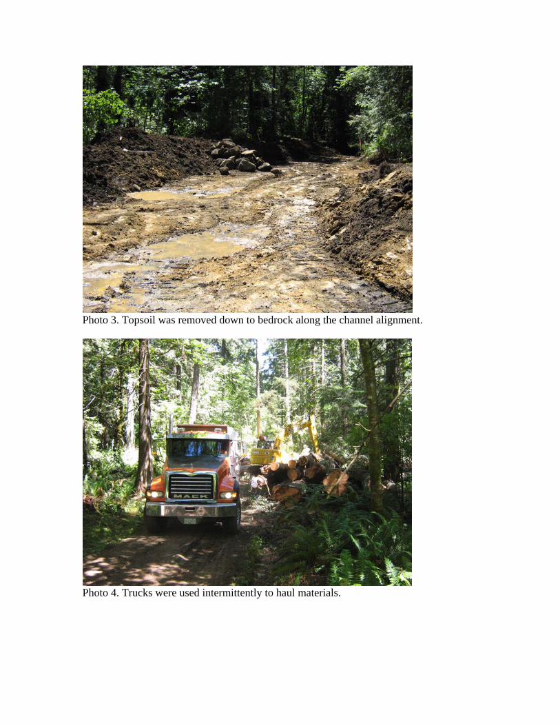
Photo 3. Topsoil was removed down to bedrock along the channel alignment.
Photo 4. Trucks were used intermittently to haul materials.
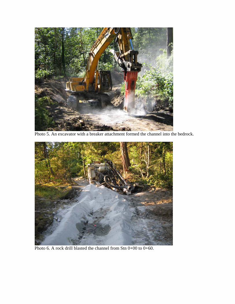
Photo 5. An excavator with a breaker attachment formed the channel into the bedrock.
Photo 6. A rock drill blasted the channel from Stn 0+00 to 0+60.

Photo 7. The old fishway was modified and the new channel was connected to the Millstone River at the base of Millstone Falls.
Photo 8. The diversion structure footing was poured first, followed by the walls.

Photo 9. The outer edges of the intake walls were poured against the bedrock.
Photo 10. A 130 mm diameter pipe and a valve were installed between the upper and lower duck ponds to help flush the lower pond.

Photo 11. A trash rack was attached to the concrete spillway/diversion wall to keep debris out of the diversion structure.
Photo 12. A trash rack and walkway grating were affixed to the intake. A handrail was also installed (not shown in photo).

Photo 13. The pond at Stn 1+60 was filled with LWD to provide fish habitat.
Photo 14. A typical 200 – 300 mm drop structure with LWD in the pool.

APPENDIX A
AS-BUILT DRAWINGS

APPENDIX B
FINANCIAL SUMMARY