
MillingCatalog07_08
108
Milling Inserts Solid Carbide, Endmills Indexable Milling Cutters Milling Adapters & Holders Tightening Fixtures & Retention Knobs Technical Information MILLING SYSTEMS ’ 07– ’ 08 HIGH PERFORMANCE MILLING TOOLS
Transcript of MillingCatalog07_08

MillingInserts
SolidCarbide,Endmills
IndexableMilling Cutters
MillingAdapters
& Holders
Tightening Fixtures &
Retention Knobs
Technical Information
MILLING SYSTEMS
’07– ’08 HIGH PERFORMANCEMILLING TOOLS

Sumitomo Electric Carbide, Inc.introduces the WorldwideWarehouse Network
Below is a list of symbols you will find in our newly revised Milling Systems Catalog.
● = Sumitomo USA stocked item★ = Sumitomo Worldwide Warehouse item▲ = Sumitomo USA limited availability item
Sumitomo Worldwide Warehouse items are available through our international locations. Items marked with a star “★” in this catalog have a two week delivery.
Sumitomo WorldwideWarehouse Network
Sumitomo Electric Carbide, Inc. Headquarters
ACP & ACK grades
WEX MillMetal Slash Mill
Spider-Mill
ACP & ACK grades
Spider-Mill
Metal Slash Mill WEX Mill
“What’s New” in this catalog...

Mill
ing
Inse
rts
MillingSystems
Table of ContentsMilling Systems: Pages
Milling Insert Nomenclature . . . . . . . . . . . . . . . 3-5
Solid Carbide Endmills . . . . . . . . . . . . . . . . . . . 7-16
Indexable Milling Cutters. . . . . . . . . . . . . . . . . 17-59
Milling Adapters and Holders . . . . . . . . . . . . . 61-84
Tightening Fixtures andRetention Knobs . . . . . . . . . . . . . . . . . . . . . . . 85-87
Technical Information . . . . . . . . . . . . . . . . . . 89-104
Index. . . . . . . . . . . . . . . . . . . . . . . . . . . . . . . . . . 105
Pages 1-104
1
Look for “Tool Tips” throughout thiscatalog for increased tooling productivity.
End
mill
Ser
ies
Wav
e M
illS
erie
sA
dapt
ers
&H
olde
rsTi
ghte
ning
Fix
ture
sTe
chni
cal
Info
rmat
ion

1-800-950-5202www.sumicarbide.com

Mill
ing
Inse
rts
Milling InsertNomenclature
Table of ContentsMilling Inserts: Pages
Milling Insert Nomenclature. . . . . . . . . . . . . . . . . 4-5
Pages 4-5
3

Milling Inserts
Milling
Inserts
4
Milling Inserts Nomenclature
Phone: (800) 950-5202 www.sumicarb ide.com
M
M M
M
T
A A A A
indexable inserts withfacets/wipers
indexable inserts withcorner radii
insertthickness
S1
D2
K3
N4
A3º
B 5º
N 0º
2 – CLEARANCE ANGLE
C7º
P11º
D15º
F25º
G30º
E20º
N
R
F
A
M
G
W
T
Q
U
B
H
C
J
X
symbol holeshape of
holechipbreaker
cylindrical hole
cylindrical hole
cylindrical hole
shape of insert’ssection
without
without
without
with
with
with
with
with
with
with
with
with
with
with
partly cylindricalhole, 40º -60°countersink
partly cylindricalhole, 40º-60°double countersink
partly cylindricalhole, 70º-90°countersink
partly cylindricalhole, 70º-90°double countersink
proprietarydesign
without
single sided
double sided
without
single sided
double sided
without
single sided
without
double sided
without
single sided
without
double sided
4 – GEOMETRY AND CLAMPING TYPE
A classes J, K, L, M, N class U classes M & N class U
.1875 – .3937" .002" .003" .003" .005"
.4375 – .5625" .003" .005" .005" .008"
.5906 – .8125" .004" .007" .006" .011"
.8661 – 1.188" .005" .010" .007" .015"
1.250 – 1.378" .006" .010v .008" 0.15"
tolerances on “A” tolerances on “M”
class A M T class A M T
A .001" .0002" .001" J .002-.005" .0002" .001"
B .001" .0002" .005" K .002-.005" .0005" .001"
C .001" .0005" .001" L .002-.005" .001" .001"
D .001" .0005" .005" M .002-.004" .002-.010" .005"
E .001" .001" .001" N .002-.004" .002-.010" .001"
F .0005" .0002" .001" P .0015" .0015" .0015"
G .001" .001" .005" U .003-.010" .005-.012" .005"
H .0005" .0005" .001" U .003-.010" .005-.012" .005"
3 – TOLERANCE CLASS (+/-)
45
26
* For shapes A, L and X,see position #1; use lengthof leading cutting edge inincrements of 1/4˝.
A symbol
1.000" 8
.750" 6
.625" 5
.500" 4
.375" 3
.250" 2
(inscribed circle “A” *)
5 – SIZE
A
L
6 – THICKNESS
T
insertthickness
.0938" 1.5
.1250" 2.1562" 2.5
.1875" 3
.2188" 3.5
.2500" 4
.3125" 5
T symbol
A
C
E
H
L
O
R
S
T
X
85
80
75
120
90
135
–
90
60
_
symbolshape insert shape nose angle
(degree)
parallelogram
rhomboid
rhomboid
hexagon
rectangle
octagon
round
square
triangle
proprietarygeometry
1 – INSERT SHAPE
Sumitomo has included information on page 4 as a reference for ANSI/ISO milling insert specifications, geometry, featuresand tolerances

Milling Inserts Nomenclature
Mill
ing
Inse
rts
5
Milling Inserts
Phone: (800) 950-5202 www.sumicarb ide.com
A7
T8
N9
610 13
F G11 12
8 – CUTTINGEDGE FORM
F
E
T
S
Sharp
Honed
T-land
Honed T-land
9 – INSERT HAND
R
L
N
direction ofcutter rotation
direction ofcutter rotation
direction ofcutter rotation
A3º
B 5º
C7º
F25º
G30º
P11º
N 0º
or less
E20º
D15º
nominal or average angle of rake oninsert face at leading cutting edgebefore edge prep and before installation
12 – RAKE FACE ANGLE
J
13 – ADDED INFO
“polished” rake face
P partial t-land
W wiper/radiused facet
D
.0312" 2
10 – FACET WIDTH
.0469" 3
.0625" 4
.0938" 6
11 – EDGE PREP SIZE
L Light–sharp or lightlyhoned and/or T-landed
G General–medium honeand/or T-land
H Heavy–large honeand/or T-land
7 – CORNER CONFIGURATION (b)
radiusr
A
K
A
leading ormajor cutting
edge
assumeddirection offeed motion
facet orwiper edge
section A-A
P
0 .004
0.5 .008
1 .1/64
2 1/32
3 3/64
4 1/16
5 5/64
6 3/32
7 7/64
8 1/8
(b) if letter is replaced by number(s),refer to table for radius “r”.
lead angle KA 3°B 5°C 7°D 15°E 20°F 25°G 30°N 0°P 11°
wiper edgeclearance P
A 45°D Handed 30°K Neutral 30°E Handed 15°F 25°G 30°N 0°P 11°
Sumitomo has included information on page 5 for cross-reference purposes only. Sumitomo inserts in this catalogdo not adhere strictly to ANSI designations. IndividualSumitomo insert descriptions and dimensions areaddressed on pages 6 through 12.

1-800-950-5202www.sumicarbide.com

End
mill
Ser
ies
Solid CarbideEndmills
Table of ContentsSolid Carbide Endmills: Pages
Endmill Series Technical Descriptions. . . . . . . . . . . . . . . . . . . . 8-10
Endmill Series Recommended Running Conditions . . . . . . . . . . . 11
UPmill Series (Four Flute) . . . . . . . . . . . . . . . . . . 12
HSI Series (Three Flute) . . . . . . . . . . . . . . . . . . . 12
SSI Series (Two & Four Flute) . . . . . . . . . . . . . . . 13
MZM/MZI Series (Two Flute) . . . . . . . . . . . . . . . . 14
MZM/MZI Series (Four Flute) . . . . . . . . . . . . . . . . 15
MZBI Series (Two & Four Flute). . . . . . . . . . . . . . 16
Pages 8-16
7

Solid Carbide
Endmills
Endm
illS
eries
8
Solid Carbide Endmills
Phone: (800) 950-5202 www.sumicarb ide.com
■ APPLICATIONSCoated Solid Carbide Endmills
• For Super Alloys, Space-age Material...Titanium alloys, Inconels, Stainless Steels,etc.• For Hard Materials (HRc35+)• For Increased Productivity...The cutting efficiency is more than 2 times
that of carbide endmills and more than 5times that of high-speed steel endmills
• For Excellent Surface Finishes
• For Longer Tool-Life...2-5 times longer tool life than carbide and
20-50 times longer than high-speed steelendmills
Uncoated Solid Carbide Endmills• For General Purpose (Under HRc35)...Carbon steels, cast irons, aluminum• For Increased Productivity• For Longer Tool-Life...8-10 times longer than HSS
Neckdiameter Shank
Neck
Cutter sweep
Body
Neck lengthCutting length Shank length
Total length
Shankdiameter
Centerhole
Cuttingdiameter
Width of land Width of radial relief
Width of marginMargin
Width of radialsecondary relief face
Radial relief angle
Radial secondary angle
Helix angle Peripheral cutting edge
Corner End cutting edge
Endgash
End relief angleEnd secondary angle
Concavity angle
Concavity
Depth offlute Tip pocket
Corediameter
Heel
Rake angleFace
Flute
Radiusof fluteCenterhole
Center cut toothWidth of land
Land
■ TECHNICAL DESCRIPTION OF AN ENDMILL

Solid Carbide Endmills
9
Solid Carbide
Endmills
Phone: (800) 950-5202 www.sumicarb ide.com
Sumitomo’s solid carbide end mills are ideal for difficult to machine materials, as well as general purposeapplications. Five styles are available – two and four flute ball nose, two and four flute square nose, and ahigh spiral three flute design. All are stocked coated and uncoated, and are manufactured from an ultra finegrain A1 carbide.
■ CoatedRecommended Applications:
UPmill Series: The new Sumitomo UPmill is the latest technology in high productivityendmilling. Its TiAlN coating gives extended tool life and higher speed capabilities than conventional carbide end mills. Optimum helixangle, large web thickness, and unique flute geometry promote superior chip evacuation with maximum tool rigidity.
SSI Series: High performance endmilling of steels, stainless steels and high-temp alloys. These tools are held to ultra-close tolerance standardsfor maximum repeatability. Coated SSI tooling features Sumitomo’sZX super-lattice coating.
HSI Series: High performance endmilling of stainless steels and high-temp alloys.These close tolerance manufactured tools offer great repeatability.The high helix design has maximum shear effect for difficult to cutmaterials. Available with or without ZX coating.
MZM & MZI Efficient general purpose endmilling of steels, cast irons andSeries: non-ferrous materials. An economical alternative to the SSI and HSI,
featuring a PVD titanium carbide wear resistant coating.
MZBI Series: General purpose ballnose endmilling of steels, cast irons, stainless steels and non-ferrous materials.
End
mill
Ser
ies

Solid Carbide
Endmills
10
Solid Carbide Endmills
Phone: (800) 950-5202 www.sumicarb ide.com
SSI SERIES CAT. NO.2 Flutes 4 Flutes High Spiral 3 Flutes
• Single End
• Square Nose
• Right-hand30° Spiral Flutes
• Single End
• Square Nose
• Right-hand30° Spiral Flutes
• Single End
• Square Nose
• Right-hand60° Spiral Flutes
HSI SERIES
• High Rigidity
• Smooth Chip Control• Close Tolerance
dimensions for superiorrepeatability
• Excellent Surface Finish• Reduced Cutting Forces in
difficult to cut materials• For Inconels, Stainless
Steels and exotic alloys
MZBI SERIES CAT. NO.2 Flutes 4 Flutes
• Single End
• Ball Nose
• Right-hand 30° Spiral Flutes
• Single End
• Ball Nose
• Right-hand 30° Spiral Flutes
• High Rigidity • Center Cutting • Excellent Surface Finishes
• Excellent Chip Control • For General Applications • Reduced Cutting Forces
# Flutes CoatedSSI412C
12/64" Dia.
MZM & MZI SERIES CAT. NO.2 Flutes 4 Flutes
• Single End
• Square Nose
• Right-hand 30° Spiral Flutes
• Single End
• Square Nose
• Right-hand 30° Spiral Flutes
• High Rigidity • For General Applications • Excellent Surface Finishes• Center Cutting • Economical• Excellent Chip Control
# Flutes Coated
MZI412C
MZM4010C
1.0mm Dia.
# Flutes Coated
12/64" Dia.
# Flutes CoatedMZBI412C
12/64” Dia.
• Enhanced tool life fromSumitomo’s ZX super latticecoating
UPmill SERIES CAT. NO.4 Flutes
• Single End
• Square Nose
• Right-hand high helix design
• High Rigidity • For General Applications• Center Cutting • TiAIN Coating• Excellent Chip Control • Excellent Surface Finishes
SSUP412Z
# Flutes Coated
12/64" Dia.
Endm
illS
eries

Solid Carbide Endmills
11
Solid Carbide
Endmills
Phone: (800) 950-5202 www.sumicarb ide.com
■ Coated
Size Speed Feed Speed Feed Speed Feed Speed Feed Speed Feed Speed Feed(mm) SFM IPT SFM IPT SFM IPT SFM IPT SFM IPT SFM IPT
-7/64 150-250 .0004- 100-200 .0003- 60-120 .0003- 100-200 .0003- 25-100 .0003 35-130 .0003-(~3.0) .0010 .0006 .0006 .0011 .0005 .0006
1/8-7/32 150-250 .0008- 100-200 .0004- 60-120 .0004- 100-200 .0005- 25-100 .0004 35-130 .0003-(3.5-6.0) .0015 .0008 .0008 .0011 .0009 .0008
1/4-3/8 150-250 .0010- 100-200 .0006- 60-120 .0006 100-200 .0008- 25-100 .0006 35-130 .0006(6.5~10.0) .0020 .0010 .0010 .0018 .0014 .0009
7/16-5/8 150-250 .0015- 100-200 .0008- 60-120 .0008- 100-200 .0011 25-100 .0009 35-130 .0006(11.0-18.0) .0030 .0015 .0015 .0028 .0021 .00153/4-1 150-250 .0020- 100-200 .0010- 60-120 .0010- 100-200 .0013 25-100 .001 35-130 .0007(19.0-25.0) 0040 .0020 .0020 .0035 .0028 .002
Material Low-Medium Carbon Steels/Alloys Tool Steels Martensitic &Stainless Steels
Austenitic &:PrecipitationHardening
Stainless SteelsExotic Alloys
~HRc 30 ~HRc 30-45 ~HRc 40-50
■ Coated
Size Speed Feed Speed Feed Speed Feed Speed Feed Speed Feed (mm) SFM IPT SFM IPT SFM IPT SFM IPT SFM IPT
-7/64 225-400 .0004- 150-250 .0002- 200-350 .0004- 100-225 .0002- 100-180 .0003(~3.0) .001 .0008 .001 .0007 .0006
1/8-7/32 225-400 .0008- 150-250 .0005- 200-350 .0008- 100-225 .0003- 100-180 .0004(3.5-6.0) .0018 .0012 .0018 .0009 .0008
1/4-3/8 225-400 .001- 150-250 .0008- 200-350 .001 100-225 .0006- 100-180 .0006(6.5~10.0) .0025 .002 .0025 .0014 .0010
7/16-5/8 225-400 .0018- 150-250 .0012- 200-350 .0018- 100-225 .0009 100-180 .0008(11.0-18.0) .0038 .0028 .0038 .0021 .00153/4-1 225-400 .0025- 150-250 .0018- 200-350 .0025- 100-225 .0015 100-180 .0010(19.0-25.0) 006 .0048 .006 .0032 .0020
Material Grey Cast Iron Ductile Iron Titanium Alloys
,220 Bhn .220 Bhn ,220 Bhn .220 Bhn
■ Uncoated
Size Speed Feed Speed Feed Speed Feed Speed Feed Speed Feed(mm) SFM IPT SFM IPT IPT SFM IPT SFM IPT
-7/64 150-250 .0004- 100-200 .0003- 100-200 .0003- 450-1100 .0005- 250-800 .0005-(~3.0) .0010 .0006 .0011 .0045 .0040
1/8-7/32 150-250 .0008- 100-200 .0004- 100-200 .0005- 450-1100 .0005- 250-800 .0005-(3.5-6.0) .0015 .0008 .0011 .0045 .0040
1/4-3/8 150-250 .0010- 100-200 .0006- 100-200 .0008- 450-1100 .0005- 250-800 .0005-(6.5~10.0) .0020 .0010 .0018 .0045 .0040
7/16-5/8 150-250 .0015- 100-200 .0008- 100-200 .0011 450-1100 .0005- 250-800 .0005-(11.0-18.0) .0030 .0015 .0028 .0045 .00403/4-1 150-250 .0020- 100-200 .0010- 100-200 .0013 450-1100 .0005- 250-800 .0005-(19.0-25.0) 0040 .0020 .0035 .0045 .0040
Material Low-Medium Carbon Steels/Alloys Cast Irons Aluminum
~HRc 30 ~HRc 30-45
High SiliconAluminum
Recommended Running Conditions
SFME
ndm
illS
erie
s
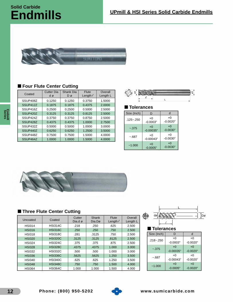
■ Tolerances
Solid Carbide
Endmills
12
UPmill & HSI Series Solid Carbide Endmills
Phone: (800) 950-5202 www.sumicarb ide.com
Cutter Shank Flute OverallUncoated Coated Dia.d ø Dia.Dø Length l Length L
■ Tolerances
■ Three Flute Center Cutting
Size (Inch) D d+0 +0
.218~.250-0.0003" -0.0020"
+0 +0~.375
-0.00035" -0.0020"+0 +0
~.687-0.00043" -0.0020"
+0 +0~1.000
-0.0005" -0.0020"
dø
l
L
Dø
HSI314HSI316HSI318HSI320HSI324HSI328HSI332HSI336HSI340HSI348HSI364
HSI314CHSI316CHSI318CHSI320CHSI324CHSI328CHSI332CHSI336CHSI340CHSI348CHSI364C
.218 .250 .625 2.500
.250 .250 .750 2.500
.281 .3125 .750 2.500.3125 .3125 .8125 2.500.375 .375 .875 2.500
.4375 .4375 1.000 3.000.500 .500 1.000 3.000
.5625 .5625 1.250 3.500.625 .625 1.250 3.500.750 .750 1.500 4.000
1.000 1.000 1.500 4.000
SSUP408Z 0.1250 0.1250 0.3750 1.5000SSUP412Z 0.1875 0.1875 0.4375 2.0000SSUP416Z 0.2500 0.2500 0.5000 2.5000SSUP420Z 0.3125 0.3125 0.8125 2.5000SSUP424Z 0.3750 0.3750 0.8750 2.5000SSUP428Z 0.4375 0.4375 1.0000 2.7500SSUP432Z 0.5000 0.5000 1.0000 3.0000SSUP440Z 0.6250 0.6250 1.2500 3.5000SSUP448Z 0.7500 0.7500 1.5000 4.0000SSUP464Z 1.0000 1.0000 1.5000 4.0000
■ Four Flute Center CuttingCutter Dia Shank Dia Flute Overall
Coated d ø D ø Length l Length LL
l
øDød
Size (Inch)
.125~.250
~.375
~.687
~1.000
D
+0-0.0003"
+0-0.00035"
+0-0.00043"
+0-0.0005"
d
+0-0.0020"
+0-0.0030"
+0-0.0030"
+0-0.0030"
Endm
illS
eries

SSI Series Solid Carbide Endmills
13
Solid Carbide
Endmills
Phone: (800) 950-5202 www.sumicarb ide.com
Cutter Shank Flute OverallUncoated Coated Dia.d ø Dia.Dø Length l Length L
SSI204 SSI204C .062 .125 .187 1.500SSI205 SSI205C .078 .125 .250 1.500SSI206 SSI206C .093 .125 .375 1.500SSI207 SSI207C .109 .125 .375 1.500SSI208 SSI208C .125 .125 .500 1.500SSI210 SSI210C .156 .1875 .562 2.000SSI212 SSI212C .1875 .1875 .725 2.000SSI214 SSI214C .218 .250 .625 2.500SSI216 SSI216C .250 .250 .750 2.500SSI218 SSI218C .281 .3125 .750 2.500SSI220 SSI220C .3125 .3125 .812 2.500SSI224 SSI224C .375 .375 .875 2.500SSI228 SSI228C .4375 .4375 1.00 3.000SSI232 SSI232C .500 .500 1.00 3.000SSI236 SSI236C .5625 .5625 1.250 3.000SSI240 SSI240C .625 .625 1.250 3.000SSI248 SSI248C .750 .750 1.500 4.000SSI264 SSI264C 1.000 1.000 1.500 4.000
■ TolerancesSize (Inch) D d
+0 +0.125~.250
-0.0003" -0.0020"+0 +0
~.375-0.00035" -0.0020"
+0 +0~.687
-0.00043" -0.0020"+0 +0
~1.000-0.0005" -0.0020"
Cutter Shank Flute OverallUncoated Coated Dia.d ø Dia.Dø Length l Length L
SSI404 SSI404C .0625 .125 .1875 1.500SSI405 SSI405C .0781 .125 .250 1.500SSI406 SSI406C .093 .125 .375 1.500SSI407 SSI407C .109 .125 .375 1.500SSI408 SSI408C .125 .125 .500 1.500SSI410 SSI410C .156 .1875 .5625 2.000SSI412 SSI412C .1875 .1875 .625 2.000SSI414 SSI414C .218 .250 .625 2.500SSI416 SSI416C .250 .250 .750 2.500SSI418 SSI418C .281 .3125 .750 2.500SSI420 SSI420C .3125 .3125 .8125 2.500SSI424 SSI424C .375 .375 .875 2.500SSI428 SSI428C .4375 .4375 1.000 3.000SSI432 SSI432C .500 .500 1.000 3.000SSI436 SSI436C .5625 .5625 1.125 3.500SSI440 SSI440C .625 .625 1.125 3.500SSI448 SSI448C .750 .750 1.500 4.000SSI464 SSI464C 1.000 1.000 1.500 4.000
■ TolerancesSize (Inch) D d
+0 +0.125~.250
-0.0003" -0.0020"+0 +0
~.375-0.00035" -0.0020"
+0 +0~.687
-0.00043" -0.0020"+0 +0
~1.000-0.0005" -0.0020"
L
l
Dødø
dø
L
Dø
l
End
mill
Ser
ies
■ Two Flute Center Cutting
■ Four Flute Center Cutting

Solid Carbide
Endmills
14
MZM/MZI Series Solid Carbide Endmills
Phone: (800) 950-5202 www.sumicarb ide.com
■ Inch Tolerances
L
l
Dødø
Size (Inch)
.125~.250
~.375
~.687
~1.000
D
+0-0.0003"
+0-0.00035"
+0-0.00043"
+0-0.0005"
d
+0-0.0020"
+0-0.0030"
+0-0.0030"
+0-0.0030"
MZM2010CMZM2015CMZM2020CMZM2025CMZM2030CMZM2035CMZM2040CMZM2045CMZM2050CMZM2055CMZM2060CMZM2065CMZM2070CMZM2075CMZM2080C
MZM2085CMZM2090C
MZM2095CMZM2100CMZM2110CMZM2120CMZM2130CMZM2140CMZM2150CMZM2160CMZM2170CMZM2180CMZM2190CMZM2200CMZM2220CMZM2250C
Cutter Shank Flute OverallUncoated Coated Dia.d ø Dia.Dø Length l Length L
MZM2010MZM2015MZM2020MZM2025MZM2030MZM2035MZM2040MZM2045MZM2050MZM2055MZM2060MZM2065MZM2070MZM2075MZM2080MZM2085MZM2090MZM2095MZM2100MZM2110MZM2120MZM2130MZM2140MZM2150MZM2160MZM2170MZM2180MZM2190MZM2200MZM2220MZM2250
1.0mm1.5mm2.0mm2.5mm3.0mm3.5mm4.0mm4.5mm5.0mm5.5mm6.0mm6.5mm7.0mm7.5mm8.0mm8.5mm9.0mm9.5mm
10.0mm11.0mm12.0mm13.0mm14.0mm15.0mm16.0mm17.0mm18.0mm19.0mm20.0mm22.0mm25.0mm
4.0mm4.0mm4.0mm4.0mm6.0mm6.0mm6.0mm6.0mm6.0mm6.0mm6.0mm8.0mm8.0mm8.0mm8.0mm
10.0mm10.0mm10.0mm10.0mm12.0mm12.0mm16.0mm16.0mm16.0mm16.0mm20.0mm20.0mm20.0mm20.0mm25.0mm25.0mm
3.0mm5.0mm6.0mm8.0mm8.0mm8.0mm
10.0mm10.0mm12.0mm12.0mm12.0mm12.0mm15.0mm15.0mm15.0mm15.0mm15.0mm15.0mm18.0mm18.0mm18.0mm20.0mm20.0mm25.0mm35.0mm35.0mm40.0mm40.0mm40.0mm40.0mm40.0mm
51.0mm51.0mm51.0mm51.0mm51.0mm51.0mm51.0mm51.0mm51.0mm51.0mm51.0mm64.0mm64.0mm64.0mm64.0mm70.0mm70.0mm70.0mm70.0mm76.0mm76.0mm88.0mm88.0mm88.0mm88.0mm
100.0mm100.0mm100.0mm100.0mm100.0mm100.0mm
■ Two Flute Center Cutting
MZI204CMZI206CMZI208CMZI210CMZI212CMZI214CMZI216CMZI218CMZI220CMZI224CMZI228CMZI232CMZI236CMZI240C
MZI244CMZI248C
MZI256CMZI264C
Cutter Shank Flute OverallUncoated Coated Dia.d ø Dia.Dø Length l Length L
MZI204MZI206MZI208MZI210MZI212MZI214MZI216MZI218MZI220MZI224MZI228MZI232MZI236MZI240MZI244MZI248MZI256MZI264
.0625 (1/16)
.0937 (3/32)
.1250 (1/8)
.1562 (5/32)
.1875 (3/16)
.2187 (7/32)
.2500 (1/4)
.2812 (9/32)
.3125 (5/16)
.3750 (3/8)
.4375 (7/16)
.5000 (1/2)
.5625 (9/16)
.6250 (5/8)
.6875 (11/16)
.7500 (3/4)
.8750 (7/8)1.0000
.1250
.1250
.1250
.1875
.1875
.2500
.2500
.3125
.3125
.3750
.4375
.5000
.5625
.6250
.6875
.7500
.87501.0000
.187
.375
.500
.562
.625
.625
.750
.750
.812
.8751.0001.0001.2501.2501.5001.5001.5001.500
1.5001.5001.5002.0002.0002.5002.5002.5002.5002.5003.0003.0003.5003.5004.0004.0004.0004.000
■ Metric TolerancesSize (mm)
1~6.4
~9.5
~17.0
~25.0
d
+0-0.0508mm
+0-0.0762mm
+0-0.0762mm
+0-0.0762mm
D
+0-0.00762mm
+0-0.00889mm
+0-0.01092mm
+0-0.01270mm
Inch
Metric
Endm
illS
eries

MZM/MZI Series Solid Carbide Endmills
15
Solid Carbide
Endmills
Phone: (800) 950-5202 www.sumicarb ide.com
Cutter Shank Flute OverallUncoated Coated Dia.d ø Dia.Dø Length l Length L
■ Four Flute Center Cutting
■ Inch Tolerances
dø
L
Dø
l
Size (Inch)
.125~.250
~.375
~.687
~1.000
d
+0-0.0020"
+0-0.0030"
+0-0.0030"
+0-0.0030"
D
+0-0.0003"
+0-0.00035"
+0-0.00043"
+0-0.0005"
■ Metric TolerancesSize (mm)
1~6.4
~9.5
~17.0
~25.0
d
+0-0.0508mm
+0-0.0762mm
+0-0.0762mm
+0-0.0762mm
D
+0-0.00762mm
+0-0.00889mm
+0-0.01092mm
+0-0.01270mm
MZM4010MZM4015MZM4020MZM4025MZM4030MZM4035MZM4040MZM4045MZM4050MZM4055MZM4060MZM4065MZM4070MZM4075MZM4080MZM4085MZM4090MZM4095MZM4100MZM4110MZM4120MZM4130MZM4140MZM4150MZM4160MZM4170MZM4180MZM4190MZM4200MZM4220MZM4250
MZM4010CMZM4015CMZM4020CMZM4025CMZM4030CMZM4035CMZM4040CMZM4045CMZM4050CMZM4055CMZM4060CMZM4065CMZM4070CMZM4075CMZM4080CMZM4085CMZM4090CMZM4095CMZM4100CMZM4110CMZM4120CMZM4130CMZM4140CMZM4150CMZM4160CMZM4170CMZM4180CMZM4190CMZM4200CMZM4220CMZM4250C
1.0mm1.5mm2.0mm2.5mm3.0mm3.5mm4.0mm4.5mm5.0mm5.5mm6.0mm6.5mm7.0mm7.5mm8.0mm8.5mm9.0mm9.5mm
10.0mm11.0mm12.0mm13.0mm14.0mm15.0mm16.0mm17.0mm18.0mm19.0mm20.0mm22.0mm25.0mm
4.0mm4.0mm4.0mm4.0mm6.0mm6.0mm6.0mm6.0mm6.0mm6.0mm6.0mm8.0mm8.0mm8.0mm8.0mm
10.0mm10.0mm10.0mm10.0mm12.0mm12.0mm16.0mm16.0mm16.0mm16.0mm20.0mm20.0mm20.0mm20.0mm25.0mm25.0mm
3.0mm5.0mm6.0mm8.0mm8.0mm8.0mm
10.0mm10.0mm12.0mm12.0mm12.0mm12.0mm15.0mm15.0mm15.0mm15.0mm15.0mm15.0mm18.0mm18.0mm18.0mm20.0mm20.0mm25.0mm35.0mm35.0mm40.0mm40.0mm40.0mm40.0mm40.0mm
51.0mm51.0mm51.0mm51.0mm51.0mm51.0mm51.0mm51.0mm51.0mm51.0mm51.0mm64.0mm64.0mm64.0mm64.0mm70.0mm70.0mm70.0mm70.0mm76.0mm76.0mm88.0mm88.0mm88.0mm88.0mm
100.0mm100.0mm100.0mm100.0mm100.0mm100.0mm
Cutter Shank Flute OverallUncoated Coated Dia.d ø Dia.Dø Length l Length L
MZI404MZI406MZI408MZI410MZI412MZI414MZI416MZI418MZI420MZI424MZI428MZI432MZI436MZI440MZI444MZI448MZI456MZI464
MZI404CMZI406CMZI408CMZI410CMZI412CMZI414CMZI416CMZI418CMZI420CMZI424CMZI428CMZI432CMZI436CMZI440CMZI444CMZI448CMZI456CMZI464C
.0625 (1/16)
.0937 (3/32)
.1250 (1/8)
.1562 (5/32)
.1875 (3/16)
.2187 (7/32)
.2500 (1/4)
.2812 (9/32)
.3125 (5/16)
.3750 (3/8)
.4375 (7/16)
.5000 (1/2)
.5625 (9/16)
.6250 (5/8)
.6875 (11/16)
.7500 (3/4)
.8750 (7/8)1.0000
.1250
.1250
.1250
.1875
.1875
.2500
.2500
.3125
.3125
.3750
.4375
.5000
.5625
.6250
.6875
.7500
.87501.0000
.1875 .375.500
.5625.625.625.750.750
.8125.875
1.0001.0001.2501.2501.5001.5001.5001.500
1.5001.5001.5002.0002.0002.5002.5002.5002.5002.5003.0003.0003.5003.5004.0004.0004.0004.000
Inch
Metric
End
mill
Ser
ies
16 Phone: (800) 950-5202 www.sumicarb ide.com
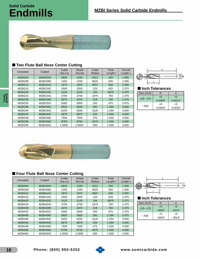
MZBI204 MZBI204C .0625 .1250 .0312 .250 1.500MZBI208 MZBI208C .1250 .1250 .0625 .500 1.500MZBI212 MZBI212C .1875 .1875 .0937 .500 2.000MZBI216 MZBI216C .2500 .2500 .125 .625 2.375MZBI220 MZBI220C .3125 .3125 .156 .6875 2.375MZBI224 MZBI224C .3750 .3759 .1875 .750 2.375MZBI228 MZBI228C .4375 .4375 .218 .750 2.375MZBI232 MZBI232C .5000 .5000 .250 .875 2.875MZBI236 MZBI236C .5625 .5625 .281 1.250 3.500MZBI240 MZBI240C .6250 .6250 .3125 1.250 3.500MZBI244 MZBI244C .6875 .6875 .343 1.500 4.000MZBI248 MZBI248C .7500 .7500 .375 1.500 4.000MZBI256 MZBI256C .8750 .8750 .4375 1.500 4.000MZBI264 MZBI264C 1.0000 1.0000 .500 1.500 4.000
■ Inch Tolerances
■ Two Flute Ball Nose Center Cutting
Size (Inch) D d+0 +0
.125~.375-0.0003" -0.0012"
+0 +0~.500
-0.0004" -0.0016"
Cutter Shank Cutter Flute OverallUncoated Coated Dia.d ø Dia.Dø Radius Length l Length L
dø
l
L
Dø
Size (Inch) D d+0 +0
.125~.375-.0003" -.0012"
+0 +0~.500
-.0004" -.0016"
MZBI404 MZBI404C .0625 .1250 .0312 .250 1.500MZBI408 MZBI408C .1250 .1250 .0625 .500 1.500MZBI412 MZBI412C .1875 .1875 .0937 .500 2.000MZBI416 MZBI416C .2500 .2500 .125 .625 2.375MZBI420 MZBI420C .3125 .3125 .156 .6875 2.375MZBI424 MZBI424C .3750 .3750 .1875 .750 2.375MZBI428 MZBI428C .4375 .4375 .218 .750 2.375MZBI432 MZBI432C .5000 .5000 .250 .875 2.375MZBI436 MZBI436C .5625 .5625 .281 1.250 3.375MZBI440 MZBI440C .6250 .6250 .3125 1.250 3.500MZBI444 MZBI444C .6875 .6875 .343 1.500 4.000MZBI448 MZBI448C .7500 .7500 .375 1.500 4.000MZBI456 MZBI456C .8750 .8750 .4375 1.500 4.000MZBI464 MZBI464C 1.0000 1.0000 .500 1.500 4.000
■ Inch Tolerances
■ Four Flute Ball Nose Center CuttingCutter Shank Cutter Flute Overall
Uncoated Coated Dia.d ø Dia.Dø Radius Length l Length L
dø
l
L
Dø
Solid Carbide
Endmills MZBI Series Solid Carbide Endmills
Endm
illS
eries

Wav
e M
illS
erie
s
17
IndexableMilling Cutters
Table of ContentsIndexable Milling Cutters: Pages
Wave SeriesWEX Endmills/Shell Mills . . . . . . . . . . . . . . . . 18-23
WEM Endmills/Shell Mills . . . . . . . . . . . . . . . . 24-26
WMM Endmills . . . . . . . . . . . . . . . . . . . . . . . . 27-28
WRM Endmills/Shell Mills . . . . . . . . . . . . . . . . 29-30
WBMR “Ballnose” Endmills . . . . . . . . . . . . . . . 31-33
WBMF Endmills. . . . . . . . . . . . . . . . . . . . . . . . 34-35(Finishing Endmill)
WGC Endmills/Shell Mills . . . . . . . . . . . . . . . . 36-39
WRC Endmills/Shell Mills . . . . . . . . . . . . . . . . 40-42(Roughing Cutter)
WFM Shell Mills . . . . . . . . . . . . . . . . . . . . . . . . . . 43
Spider Mill Shell Mills . . . . . . . . . . . . . . . . . . . . . . 44
MS Mill Shell Mills . . . . . . . . . . . . . . . . . . . . . . . . 45
UFO SeriesUFO Endmills/Shell Mills . . . . . . . . . . . . . . . . . 46-48
UFOR Shell Mills . . . . . . . . . . . . . . . . . . . . . . . . . 49
sumiMill SeriesCHE Endmills . . . . . . . . . . . . . . . . . . . . . . . . . 50-51
APG Face Mills. . . . . . . . . . . . . . . . . . . . . . . . . . . 52
DNF Face Mills . . . . . . . . . . . . . . . . . . . . . . . . . . . 53
CHG Face Mills . . . . . . . . . . . . . . . . . . . . . . . . . . 54
CPG Face Mills . . . . . . . . . . . . . . . . . . . . . . . . . . 55
DPG Face Mills . . . . . . . . . . . . . . . . . . . . . . . . 56-57
EHG Face Mills . . . . . . . . . . . . . . . . . . . . . . . . . . 58
FPG Face Mills . . . . . . . . . . . . . . . . . . . . . . . . . . . 59
Pages 18-59

Features & Benefits
WEX Type
Wave M
illS
eries
18
Wave Mill Series Indexable Endmills
PocketingPocketingPocketing Helical BoringHelical BoringHelical Boring SlottingSlottingSlotting Shoulder MillingShoulder MillingShoulder Milling RampingRampingRamping
Tough, sharp and highl y accurate cutting edge geometry
• The unique shape and strength of the cutting edge has been improved resulting in reduced cutting forces
• Insert facet generates high quality surface finishes
Wide selection of inser t geo metries and grades
• Available in 3 different geometries (L, G, and H)
• A wide range of machining applications due to the new "Super ZX" coating and CVD "Super FF" coating for steel and iron
- 100- 500501000
5
10
15
20
25
WEX31250EWCompetitor's productConventional product
16m m
24 mm
8 mm
0 mm
5mm
High efficiency machining due to its optimized cutting edge geometry and highly rigid body
Highl y durab le
• Cutter body and insert strength provide for high feed rate capabilities
Coolant holes
• Efficient chip removal due to new air/coolant hole design
For a widerange ofapplications
Utiliz es the ne w multi-la yered
PVD "Super ZX" coatingand CVD "Super FF" coating
• Shoulder accuracy generated in profile machining
Minimal depth ofcut variation due
to assembly precision!
Minimal depth ofcut variation due
to assembly precision!
Dep
th o
f Mac
hine
d S
houl
der
(mm
)
Hei
ght o
f Wal
l Sur
face
(m
m)
1st Cut(8mm)
2nd Cut(8mm)
3rd Cut(8mm)
■ Cutting Performance

5o20o25o -L
■ Chipbreaker Selection GuideSteel, Stainless Steel, Cast IronWork Material
InsertGeometry
-L -G -H
Characteristics Light Cutting Multi-purpose High Strength
InsertCross Section
ApplicationLight DOC,
Low rigidity conditionsGeneral purpose
applicationsHeavy cuttingapplications
-G
-H
Edge Strength
Cut
ting
For
ce
ACP100
ACP200
ACP300
ACK300
ACK200General purpose grade that features the new "Super FF" CVD coating for machining gray and ductile cast irons.
ACP300 features the new "Super ZX" coating improving the toughness and chipping resistance in difficult to machine materials.
ACP200 is a general grade for steels that provides excellent wear and chipping resistance due to the new "Super ZX" coating and tough carbide substrate.
Excellent wear and thermal crack resistance in steels, with the new "Super FF" CVD coating containing a fine grain Ti-based layer.
ACK300 with "Super ZX" PVD coating for milling heavily interrupted gray and ductile irons.
Al 2O3
Al 2O3
TiAIN/AlCrN
TiAIN/AlCrN
TiAIN/AlCrN
Grade Coating Description
■ Grade Applications
■ Application Range
P10/M10/C7 P20/M20/C6 P30/M30/C5A P40/M40/C5
ACP100ACP100P
M
ACK200ACK300
ACK200ACK300
K
K01 K10 K20 K30
Material
Material
ACP200ACP200
ACP300ACP300
Wave Mill Series Indexable Endmills
Wav
e M
illS
erie
s
19
Grade Selection Guide
WEX Endmills
ACP100 775-1310 725-1275 675-1225 .006-.0125Low and Medium Carbon Steels <250 Bhn ACP200 721-1213 675-1180 600-1125 .006-.0135
ACP300 675-1075 650-1025 525-925 .006-.014ACP100 600-975 575-950 550-900 .006-.0095
<250 Bhn ACP200 550-900 525-900 500-875 .006-.0115ACP300 525-875 500-825 475-800 .006-.0115ACP100 600-975 575-950 550-900 .006-.011
Medium-High Carbon Steels <250 Bhn ACP200 575-950 550-925 500-875 .006-.012ACP300 575-950 550-925 500-875 .006-.012ACP100 725-1300 700-1250 675-1200 .006-.0135
Free Machining Steels and Alloys <250 Bhn ACP200 750-1325 725-1275 675-1225 .006-.0135ACP300 675-1075 650-1050 650-1025 .006-.014ACP100 475-820 450-790 425-750 .0047-.010
<250 Bhn ACP200 450-820 435-790 425-750 .0047-.011ACP300 450-820 425-790 400-725 .0047-.012ACP100 400-775 400-735 400-700 .004-.009ACP200 425-750 400-725 375-690 .0045-.010ACP300 420-700 420-695 375-685 .0047-.012ACP100 325-650 300-625 300-590 .003-.007ACP200 325-650 300-625 300-590 .0045-.0095ACP200 535-850 520-830 275-820 .004-.011ACP300 525-840 515-820 250-800 .004-.012ACP200 435-750 420-720 175-700 .004-.011ACP300 425-740 415-720 175-675 .004-.012ACP200 325-875 300-850 275-825 .004-.011ACP300 300-850 275-825 250-800 .004-.012ACK200 700-1050 625-925 590-900 .004-.014ACK300 600-950 575-875 550-850 .004-.014ACK200 600-950 525-825 490-800 .004-.014ACK300 500-850 475-775 450-750 .004-.014ACK200 600-925 550-875 490-800 .004-.012ACK300 550-825 550-825 450-750 .004-.012ACK200 100-160 70-150 60-135 .003-.0075ACK300 100-160 70-150 60-135 .004-.0075
ISO
P
M
K
S
Material Hardness Grade .002-.050Depth of Cut
.050-.125 .125 & overFeed per
tooth
>33 Hrc
Bhn 220-350
<250 Bhn
>250 Bhn
<250 Bhn
<250 Bhn
>250 Bhn
<320 Bhn
Medium Carbon Alloy Steels4140, 4340, 5130, 8620
Tool Steels
Martensitic and Ferritic StainlessSteels 414, 416, 430, 440
Austenitic and Precipitation HardeningStainless Steels 303, 304, 316, 321, etc.
Gray Cast Iron
Ductile Iron
Exotic Alloys Inconel, Hastalloy,Waspalloy, etc.
■ Grade Applications

See pages 102-104for recommended running
parameters
141414
LLL
lll 222lll111
øøød d døøøDDD
■ Inch
141414
LLL
lll 222lll111
øøød d døøøDDD
Catalog Number Stock Ramp InsertD d L l1 l2
Angle Qty.Dimensions (inch)
■ WEX 2000 Weldon Shank Series
WEX20500EW O 0.500 0.750 3.325 1.309 2.031 5o 1WEX20625EW • 0.625 0.625 3.218 1.312 1.906 4o 2WEX20625EMW O 0.625 0.625 3.591 1.685 1.906 4o 2WEX20750EW • 0.750 0.750 3.561 1.530 2.031 4o 3WEX20750EMW O 0.750 0.750 4.091 2.060 2.031 4o 3WEX20750ELW O 0.750 0.750 5.091 3.060 2.031 4o 3WEX21000EW • 1.000 1.000 3.811 1.530 2.281 2o 4WEX21250EW O 1.250 1.250 4.531 2.250 2.281 1o30’ 5
Catalog Number Stock Ramp InsertD d L l1 l2
Angle Qty.Dimensions (mm)
■ WEX 2000 Shank Series Standard type
WEX2014E ★ 14 16 80 25 55 5o 1WEX2016E ★ 16 16 100 25 75 4o 2WEX2018E ★ 18 16 100 25 75 4o 2WEX2020E ★ 20 20 110 30 80 4o 3WEX2022E ★ 22 20 110 30 80 4o 3WEX2025E ★ 25 25 120 35 85 2o 4WEX2028E ★ 28 25 120 35 85 1o30’ 4WEX2030E ★ 30 25 120 35 85 1o30’ 4WEX2032E ★ 32 32 130 40 90 1o30’ 5WEX2040E ★ 40 32 150 30 120 1o 6WEX2050E ★ 50 32 150 30 120 0o30’ 7WEX2063E ★ 63 32 150 30 120 0o30’ 8
• USA stocked itemO New product arrives 1st quarter 2007
■ WEX 2000 Inserts
Coated
Sumitomo Cat. No.
Dimensions (Inches)
AC
P10
0A
CP
200
AC
P30
0A
CK
200
AC
K30
0
★ • • • • ★ • • ★ ★
★ • • • •★ • • ★ ★
★ ★ ★ ★ ★
★ ★ ★ ★ ★
AXMT123504PEERGAXMT123504PEERHAXMT123508PEERGAXMT123508PEERHAXMT123512PEERGAXMT123512PEERH
• USA stocked item★ Worldwide Warehouse item
L W T RFacetWidth
.472 .260 .138 .016 .061
.472 .260 .138 .016 .061
.472 .260 .138 .031 .061
.472 .260 .138 .031 .061
.472 .260 .138 .047 .061
.472 .260 .138 .047 .061
R L T
W
11˚
■ Metric
★ Worldwide Warehouse item
Catalog Number Stock Ramp InsertD d L l1 l2
Angle Qty.Dimensions (mm)
■ WEX 2000 Shank Series Long type
WEX2014EL ★ 14 16 120 25 95 5o 1WEX2016EL ★ 16 16 145 25 120 4o 2WEX2018EL ★ 18 16 145 25 120 4o 2WEX2020EL ★ 20 20 150 40 110 4o 2WEX2022EL ★ 22 20 150 30 120 4o 2WEX2025EL ★ 25 25 170 50 120 2o 2WEX2028EL ★ 28 25 170 30 140 1o30’ 2WEX2030EL ★ 30 25 170 30 140 1o30’ 2WEX2032EL ★ 32 32 180 60 120 1o30’ 2WEX2040EL ★ 40 32 180 30 150 1o 2
★ Worldwide Warehouse item
■ Hardware (Inch)
* Torque specifications for insert screw=18-22 in/lbs.
Insert Screw* Insert WrenchCatalog Number
WEX20500-WEX20625 BFTX0305IP
BFTX0306IPWEX20750-WEX21250
TRDR08IP
TRDR08IP
■ Hardware (Metric)
* Torque specifications for insert screw=18-22 in/lbs.
Insert Screw* Insert WrenchCatalog Number
WEX2014-WEX2018 BFTX0305IP
BFTX0306IPWEX2020-WEX2063
TRDR08IP
TRDR08IP
Inch Applicable Insert:
WEX 2000 AXMT
Wave M
illS
eries
20 Phone: (800) 950-5202 www.sumicarb ide.com
Metric Applicable Insert:
WEX 2000 AXMT

Wave Mill Series Indexable Endmills
Wav
e M
illS
erie
s
21
Inch & Metric Applicable Insert:
WEX 2000 AXMT
Phone: (800) 950-5202 www.sumicarb ide.com
See pages 102-104for recommended running
parameters
ht
14H
a
ød1
øD ød2
1.5002.0002.500
0.7500.7501.000
0.3120.3120.375
0.4530.4060.531
0.1870.1870.218
1.5621.5621.562
0.7500.7500.750
678
2o
1o
0o30’
D d1 a Hd2 t hRampAngle
InsertQty.
WEX21500RWEX22000RWEX22500R
Dimensions (Inches)
■ WEX 2000 Shell Mill Series (Inch)
CatalogNumber
Stock
O New product arrives 1st quarter 2007
O
O
O
405063
162222
8.410.410.4
91111
5.66.36.3
404040
678
182020
2o
1o
0o30’
D d1 a Hd2 t hInsertQty.
RampAngle
WEX2040FWEX2050FWEX2063F
Dimensions (mm)
■ WEX 2000 Shell Mill Series (Metric)
CatalogNumber
Stock
★ Worldwide Warehouse item
★
★
★
■ WEX 2000 Inserts
Coated
Sumitomo Cat. No.
Dimensions (Inches)
AC
P10
0A
CP
200
AC
P30
0A
CK
200
AC
K30
0
★ • • • • ★ • • ★ ★
★ • • • •★ • • ★ ★
★ ★ ★ ★ ★
★ ★ ★ ★ ★
AXMT123504PEERGAXMT123504PEERHAXMT123508PEERGAXMT123508PEERHAXMT123512PEERGAXMT123512PEERH
• USA stocked item★ Worldwide Warehouse item
L W T RFacetWidth
.472 .260 .138 .016 .061
.472 .260 .138 .016 .061
.472 .260 .138 .031 .061
.472 .260 .138 .031 .061
.472 .260 .138 .047 .061
.472 .260 .138 .047 .061
R L T
W
11˚
■ Hardware (Inch)
* Torque specifications for insert screw=18-22 in/lbs.
Insert Screw* Insert WrenchCatalog Number
WEX21500-WEX22500 BFTX0306IP TRDR08IP
■ Hardware (Metric)
* Torque specifications for insert screw=18-22 in/lbs.
Insert Screw* Insert WrenchCatalog Number
WEX2040-WEX2063 BFTX0306IP TRDR08IP

141414
LLL
lll 222lll111
øøød d døøøDDD
Catalog Number Stock Ramp InsertD d L l1 l2
Angle Qty.Dimensions (mm)
■ WEX 3000 Shank Series Standard Type
■ Metric
WEX3025E ★ 25 25 120 35 85 5o 2WEX3032E ★ 32 32 130 40 90 3o 3WEX3040E ★ 40 32 170 50 120 2o 4WEX3050E ★ 50 32 170 50 120 1o 5WEX3063E ★ 63 32 170 50 120 0o30’ 6
★ Worldwide Warehouse item
Catalog Number Stock Ramp InsertD d L l1 l2
Angle Qty.Dimensions (mm)
■ WEX 3000 Shank Series Long Type
WEX3025EL ★ 25 25 170 50 120 5o 2WEX3028EL ★ 28 25 170 50 120 5o 2WEX3030EL ★ 30 25 180 60 120 5o 2WEX3032EL ★ 32 32 180 60 120 3o 2WEX3035EL ★ 35 32 180 60 120 2o 2WEX3040EL ★ 40 32 220 80 140 2o 2
★ Worldwide Warehouse item
Catalog Number Stock Ramp InsertD d L l1 l2
Angle Qty.Dimensions (mm)
■ WEX 3000 Shank Series Short Type
WEX3050ES ★ 50 32 135 25 110 1o 5WEX3063ES ★ 63 32 135 25 110 0o30’ 6
★ Worldwide Warehouse item
Catalog Number Stock Ramp InsertD d L l1 l2
Angle Qty.Dimensions (mm)
■ WEX 3000 Shank Series Short & Coarse Pitch Type
WEX3050ES-C ★ 50 32 135 25 110 1o 3WEX3063ES-C ★ 63 32 135 25 110 0o30’ 4
★ Worldwide Warehouse item
Catalog Number Stock Ramp InsertD d L l1 l2
Angle Qty.Dimensions (mm)
■ WEX 3000 Shank Series Coarse Pitch Type
WEX3040E-C ★ 40 32 170 50 120 2o 3WEX3050E-C ★ 50 32 170 50 120 1o 3WEX3063E-C ★ 63 32 170 50 120 0o30’ 4
★ Worldwide Warehouse item
141414
LLL
lll 222lll111
øøød d døøøDDD
Catalog Number Stock Ramp InsertD d L l1 l2
Angle Qty.Dimensions (inch)
■ WEX 3000 Weldon Shank Series
■ Inch
WEX31000EW • 1.000 1.000 3.811 1.530 2.281 5o 2WEX31000EMW O 1.000 1.000 4.841 2.560 2.281 5o 2WEX31000ELW O 1.000 1.000 6.341 4.060 2.281 5o 2WEX31250EW • 1.250 1.250 4.531 2.250 2.281 3o 3WEX31250EMW O 1.250 1.250 6.381 4.100 2.281 3o 3WEX31500EW • 1.500 1.250 4.531 2.250 2.281 2o 4WEX32000EW O 2.000 1.250 4.531 2.250 2.281 2o 5
• USA stocked itemO New product arrives 1st quarter 2007
■ WEX 3000 Inserts
Coated
Sumitomo Cat. No.
Dimensions (Inches)
AC
P10
0A
CP
200
AC
P30
0A
CK
200
AC
K30
0D
L100
0H
1
★ ★ ★ ★ ★
★ ★ ★ ★ ★
★ • • • •★ • • ★ ★
★ ★ ★ ★ ★
★ ★
★ • • ★ ★
★ ★
★ ★
★ ★
AXMT170504PEERGAXMT170508PEERLAXMT170508PEERGAXMT170508PEERHAXMT170512PEERGAXMT170512PEERHAXMT170516PEERGAXET170502PEFRSAXET170504PEFRSAXET170508PEFRS
• USA stocked item★ Worldwide Warehouse item
L W T RFacetWidth
.689 .402 .219 .016 .118
.689 .402 .219 .031 .118
.689 .402 .219 .031 .118
.689 .402 .219 .031 .118
.689 .402 .219 .047 .118
.689 .402 .219 .047 .118
.689 .402 .219 .063 .118
.689 .402 .219 .008 .118
.689 .402 .219 .016 .118
.689 .402 .219 .031 .118
R L T
W
11˚
■ Hardware (Inch)
* Torque specifications for insert screw=27-31 in/lbs.
Insert Screw* Insert WrenchCatalog Number
WEX31000 BFTX0407IP
BFTX0409IPWEX31250-WEX32000
TRDR15IP
TRDR15IP
■ Hardware (Metric)
* Torque specifications for insert screw=27-31 in/lbs.
Insert Screw* Insert WrenchCatalog Number
WEX3025 BFTX0407IP
BFTX0409IPWEX3032-WEX3063
TRDR15IP
TRDR15IP
Wave M
illS
eries
22 Phone: (800) 950-5202 www.sumicarb ide.com
Inch Applicable Insert:
WEX 3000 AXMTAXET
Metric Applicable Insert:
WEX 3000 AXMTAXET
See pages 102-104for recommended running
parameters

ht
14H
a
ød1
øD ød2
2.0002.5003.0003.0004.0004.000
0.7501.0001.0001.0001.2501.250
0.3120.3750.3750.3750.5000.500
0.4060.5310.5310.5310.6560.655
0.1870.2180.2180.2180.2810.281
1.5621.5621.7501.7502.0002.000
0.7500.7500.7500.7500.7500.750
565768
1o
0o30’0o30’0o30’N/AN/A
D d1 a Hd2 t hRampAngle
InsertQty.
WEX32000RWEX32500R
WEXC33000RWEX33000R
WEXC34000RWEX34000R
Dimensions (Inches)
■ WEX 3000 Shell Mill Series (Inch)
CatalogNumber
Stock
• USA stocked itemO New product arrives 1st quarter 2007
•• O
• O
•
40506380
100125
162222
25.4031.7538.10
8.410.410.49.5
12.715.9
9111113––
5.66.36.368
10
404040506363
456456
18202025––
2o
1o
0o30’0o30’N/AN/A
D d1 a Hd2 t hInsertQty.
RampAngle
WEX3040FWEX3050FWEX3063FWEX3080RWEX3100RWEX3125R
Dimensions (mm)
■ WEX 3000 Shell Mill Series Standard Type (Metric)
CatalogNumber
Stock
★ Worldwide Warehouse item
★
★
★
★
★
★
80100125
25.4031.7538.10
9.512.715.9
13––
68
10
506363
789
0o30’N/AN/A
25––
D d1 a Hd2 t hInsertQty.
RampAngle
WEXF3080RWEXF3100RWEXF3125R
Dimensions (mm)
■ WEX 3000 Shell Mill Series Fine Pitch Type (Metric)
CatalogNumber
Stock
★ Worldwide Warehouse item
★
★
★
■ WEX 3000 Inserts
Coated
Sumitomo Cat. No.
Dimensions (Inches)
AC
P10
0A
CP
200
AC
P30
0A
CK
200
AC
K30
0D
L100
0H
1
★ ★ ★ ★ ★
★ ★ ★ ★ ★
★ • • • •★ • • ★ ★
★ ★ ★ ★ ★
★ ★
★ • • ★ ★
★ ★
★ ★
★ ★
AXMT170504PEERGAXMT170508PEERLAXMT170508PEERGAXMT170508PEERHAXMT170512PEERGAXMT170512PEERHAXMT170516PEERGAXET170502PEFRSAXET170504PEFRSAXET170508PEFRS
• USA stocked item★ Worldwide Warehouse item
L W T RFacetWidth
.689 .402 .219 .016 .118
.689 .402 .219 .031 .118
.689 .402 .219 .031 .118
.689 .402 .219 .031 .118
.689 .402 .219 .047 .118
.689 .402 .219 .047 .118
.689 .402 .219 .063 .118
.689 .402 .219 .008 .118
.689 .402 .219 .016 .118
.689 .402 .219 .031 .118
R L T
W
11˚
■ Hardware (Inch)
* Torque specifications for insert screw=27-31 in/lbs.
Insert Screw* Insert WrenchCatalog Number
WEX32000-WEX34000 BFTX0409IP TRDR15IP
■ Hardware (Metric)
* Torque specifications for insert screw=27-31 in/lbs.
Insert Screw* Insert WrenchCatalog Number
WEX3040-WEX3125 BFTX0409IP TRDR15IP
Wave Mill Series Indexable Endmills
Wav
e M
illS
erie
s
23Phone: (800) 950-5202 www.sumicarb ide.com
Inch & Metric Applicable Insert:
WEX 3000 AXMTAXET
See pages 102-104for recommended running
parameters

APMT APET
WEM Type
Wave M
illS
eries
24
Wave Mill Series Indexable Endmills
Phone: (800) 950-5202 www.sumicarb ide.com
■ Features and Benefits
• Advanced high performance design
• Thick, super high rake inserts combine strong performance atheavy feed rates with an easy, free cutting design
• Extended tool life from Sumitomo’s advanced ZX super-latticecoated carbide grades
• Accepts economical M class APMT inserts as well as the newprecision ground APET inserts for situations that demand thevery best surface finish when face milling
• Offered in both coarse and fine pitch, 10 mm and 16 mm insertconfigurations, and a variety of lengths for regular as well asunusual machining applications
• Uses the same inserts as our popular WMM and WRM millingcutters for simple insert management
• Expanded selection of longer length bodies allow extendedreach over Sumitomo’s previous selection
• Each medium or long tool is fully relieved to allow formachining sidewalls from the tool tip all the way to the face ofan ISO design Weldon shank tool holder
■ APMT inserts
• Wave shape cutting edge
• Thick insert for improved rigidity
• High rake angle for low cutting resistance
• “M” class specifications provide high productivity at modest prices
■ APET inserts
• Wave shape cutting edge
• High rake angle for low cutting resistance
• Fully ground periphery guarantees consistent repeatability
• Integral wiper flat produces superior surface finishes
• APET inserts are available in a wide variety of high performance grades
■ Wave Inserts for WEM, WMM and WRC Cutters
Shank type
Shell type
Wave-shaped cutting edge
Improved rigidity dueto thicker insert
High rake angle forLow cuttingforces

Catalog Number Ramp # ofØD Ød L R l1 l2
Angle InsertsDimensions (Inches)
■ Weldon Shank Series
Sto
ck
Wav
e M
illS
erie
s
25Phone: (800) 950-5202 www.sumicarb ide.com
Inch Applicable Insert:
WEM 3000 APET10APMT10
Inch Applicable Insert:
WEM 3000 APET10APMT10
Torque specifications for BFTX02506N insertscrew=10-14 inch/lbs.
■ Hardware
WEM3■■■■■■RW■■ BFTX02506N TRD08WEM3■■■■EX BFTX02506N TRD08
Catalog Number Screw Wrench
■ Inserts
Coated
Sumitomo Cat. No.
Uncoated Dimensions (Inches)
Figure 1 Figure 2
AC
Z31
0A
CZ
330
AC
Z35
0D
L100
0H
1
• • •• •
• • •• • •• •• •• •• •
APET103504PDERAPET103504PDFR-JAPMT103504PDERAPMT103504PDER-HAPMT103508PDERAPMT103508PDER-HAPMT103512PDERAPMT103512PDER-H
R
L
W
FW
R
L
W30˚
T
“J” denotes inserts with a polished face.“H” denotes inserts with heavy edge preparation.
• = USA stocked item
Ramp angle for WEM315EX = 1o
Ramp angle for WEM320EX - WEM325EX = 0o 30’
• = USA stocked item
# ofD d1 d2 a H h t Teeth
Dimensions (Inches)
■ WEM Shell Mill Series
WEM315EX • 1.500 0.750 0.453 0.312 1.562 0.750 0.187 6WEM320EX • 2.000 0.750 0.453 0.312 1.562 0.750 0.187 7WEM325EX • 2.500 1.000 0.531 0.375 1.562 0.750 0.218 9
L W T RFacetWidth
Fig.
0.394 0.250 0.138 0.016 0.0315 10.394 0.250 0.138 0.016 0.0315 10.394 0.250 0.138 0.016 N/A 20.394 0.250 0.138 0.016 N/A 20.394 0.250 0.138 0.031 N/A 20.394 0.250 0.138 0.031 N/A 20.394 0.250 0.138 0.047 N/A 20.394 0.250 0.138 0.047 N/A 2
CatalogNumber S
tock
See pages 102-104for recommended running
parameters
Always choose the shortestpossible tool for the job
• = USA stocked item
WEM3108RW • 0.500 0.750 3.325 1.294 1.309 2.031 6o 1WEM3210RW • 0.625 0.625 3.375 1.000 1.482 2.375 4o 2WEM3212RW • 0.750 0.750 3.625 1.250 1.609 2.375 2o 30’ 2WEM3312RW • 0.750 0.750 3.625 1.250 1.609 2.375 2o 30’ 3WEM3212RWM • 0.750 0.750 5.075 3.044 3.044 2.031 2o 30’ 2WEM3312RWM • 0.750 0.750 5.075 3.044 3.044 2.031 2o 30’ 3WEM3314RW • 0.875 0.750 3.625 1.250 1.609 2.375 2o 3WEM3216RW • 1.000 0.750 3.750 1.375 1.784 2.375 2o 2WEM3416RW • 1.000 0.750 3.750 1.375 1.734 2.375 2o 4WEM3216RWM • 1.000 1.000 5.560 3.279 3.279 2.281 2o 2WEM3416RWM • 1.000 1.000 6.320 4.039 4.039 2.281 2o 4WEM3418RW • 1.125 1.000 3.937 1.375 1.6764 2.562 1o 30’ 4WEM3320RW • 1.250 1.250 4.060 1.779 1.779 2.281 1o 30’ 3WEM3520RW • 1.250 1.000 3.937 1.375 1.687 2.562 1o 30’ 5WEM3320RWM • 1.250 1.250 6.325 4.044 4.044 2.281 1o 30’ 3WEM3520RWM • 1.250 1.250 6.325 4.044 4.044 2.281 1o 30’ 5WEM3624RW • 1.500 1.000 4.375 1.625 2.1144 2.750 1o 6WEM3624RWM • 1.500 1.500 6.750 4.062 4.062 2.688 1o 6WEM3624RWL • 1.500 1.500 8.250 5.562 5.562 2.688 1o 6WEM3732RW • 2.000 1.000 4.375 1.625 2.1144 2.750 0o 30’ 7
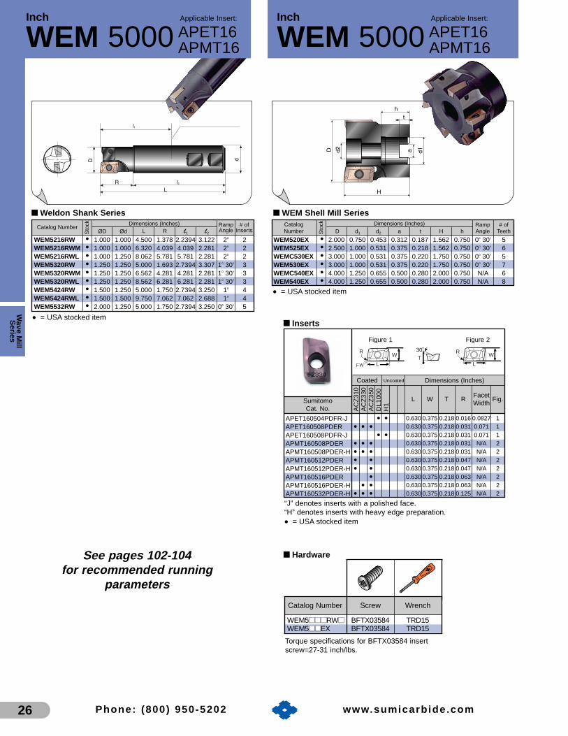
Inch Applicable Insert:
WEM 5000
Wave M
illS
eries
26 Phone: (800) 950-5202 www.sumicarb ide.com
Inch Applicable Insert:
WEM 5000 APET16APMT16
APET16APMT16
■ Weldon Shank SeriesRamp # of
D d1 d2 a t H h Angle TeethDimensions (Inches)
■ WEM Shell Mill Series
WEM520EX • 2.000 0.750 0.453 0.312 0.187 1.562 0.750 0o 30’ 5WEM525EX • 2.500 1.000 0.531 0.375 0.218 1.562 0.750 0o 30’ 6WEMC530EX • 3.000 1.000 0.531 0.375 0.220 1.750 0.750 0o 30’ 5WEM530EX • 3.000 1.000 0.531 0.375 0.220 1.750 0.750 0o 30’ 7WEMC540EX • 4.000 1.250 0.655 0.500 0.280 2.000 0.750 N/A 6WEM540EX • 4.000 1.250 0.655 0.500 0.280 2.000 0.750 N/A 8
CatalogNumber
Torque specifications for BFTX03584 insertscrew=27-31 inch/lbs.
■ Hardware
WEM5■■■■■■RW■■ BFTX03584 TRD15WEM5■■■■EX BFTX03584 TRD15
Catalog Number Screw Wrench
Sto
ck■ Inserts
Coated
Sumitomo Cat. No.
Uncoated Dimensions (Inches)
Figure 1 Figure 2
AC
Z31
0A
CZ
330
AC
Z35
0D
L100
0H
1
• •• • •
• •• • •• • •• •• •
•• •
• • •
APET160504PDFR-JAPET160508PDERAPET160508PDFR-JAPMT160508PDERAPMT160508PDER-HAPMT160512PDERAPMT160512PDER-HAPMT160516PDERAPMT160516PDER-HAPMT160532PDER-H
R
L
W
FW
R
L
W30˚
T
“J” denotes inserts with a polished face.“H” denotes inserts with heavy edge preparation.
• = USA stocked item
L W T RFacetWidth
Fig.
0.630 0.375 0.218 0.016 0.0827 10.630 0.375 0.218 0.031 0.071 10.630 0.375 0.218 0.031 0.071 10.630 0.375 0.218 0.031 N/A 20.630 0.375 0.218 0.031 N/A 20.630 0.375 0.218 0.047 N/A 20.630 0.375 0.218 0.047 N/A 20.630 0.375 0.218 0.063 N/A 20.630 0.375 0.218 0.063 N/A 20.630 0.375 0.218 0.125 N/A 2
See pages 102-104for recommended running
parameters
• = USA stocked item
• = USA stocked item
Catalog Number Ramp # ofØD Ød L R l1 l2
Angle InsertsDimensions (Inches)
Sto
ck
WEM5216RW • 1.000 1.000 4.500 1.378 2.2394 3.122 2o 2WEM5216RWM • 1.000 1.000 6.320 4.039 4.039 2.281 2o 2WEM5216RWL • 1.000 1.250 8.062 5.781 5.781 2.281 2o 2WEM5320RW • 1.250 1.250 5.000 1.693 2.7394 3.307 1o 30’ 3WEM5320RWM • 1.250 1.250 6.562 4.281 4.281 2.281 1o 30’ 3WEM5320RWL • 1.250 1.250 8.562 6.281 6.281 2.281 1o 30’ 3WEM5424RW • 1.500 1.250 5.000 1.750 2.7394 3.250 1o 4WEM5424RWL • 1.500 1.500 9.750 7.062 7.062 2.688 1o 4WEM5532RW • 2.000 1.250 5.000 1.750 2.7394 3.250 0o 30’ 5

Wav
e M
illS
erie
s
27Phone: (800) 950-5202 www.sumicarb ide.com
Wave Mill Series Indexable Endmills WMM Type■ Features and Benefits
• Multifunctional cutter efficiently performs the cutting operationsof several tools
• Excellent for ramping, helical cutting, pocketing, and drilling
• Inserts interchangeable with those used on the WEM and WRM cutters
• Strong high rake inserts provide smooth cutting action
Peripheral insert
Staggered peripheral inserts lower cutting forceduring shoulder milling and slotting
Center insert overlaps cutter center lineto produce plunge cutting capabilities
Peripheral insert Centerinsert
■ Insert orientation of WMM type cutter
■ Multi-purpose Applications
Shoulder milling Slotting Ramping
Pocketing Drilling Helical boringBoring-expanding
Max. depth = effective depth of cutRamping Angle = 0~30°
• a hole of 1.2-1.8 x diameter withoutprepared hole
• Helical angle = 0° to 30°
Always use step feed (.020˝-.040˝) whendrilling. It is recommended that the drilldepth is #0.6D.

øD ød
L
l3
l1
l2
Catalog Number l3 Max # ofØD Ød L l1 l2 D.O.C. Inserts
Dimensions (Inches)
■ WMM Endmills
WMM16150M • 1.500 1.250 5.000 2.7394 2.281 1.540 4
Sto
ck
Torque specifications for BFTX03584 insertscrew=27-31 inch/lbs.
■ Hardware
WMM16■■■■■■M BFTX03584 TRD15
Catalog Number Screw Wrench
øD ød
L
l3
l1
l2
Catalog Number l3 Max # ofØD “Ød L l1 l2 D.O.C. Inserts
Dimensions (Inches)
■ WMM Endmills
WMM10100M • 1.000 1.000 4.000 1.7394 2.281 1.050 4WMM10125M • 1.250 1.250 5.000 2.7394 2.281 1.390 5
Sto
ck
■ Inserts
Coated
Sumitomo Cat. No.
Uncoated Dimensions (Inches)
Figure 1 Figure 2
AC
Z31
0A
CZ
330
AC
Z35
0D
L100
0H
1
• • •• •
• • •• • •• •• •• •• •
APET103504PDERAPET103504PDFR-JAPMT103504PDERAPMT103504PDER-HAPMT103508PDERAPMT103508PDER-HAPMT103512PDERAPMT103512PDER-H
R
L
W
FW
R
L
W30˚
T
“J” denotes inserts with a polished face.“H” denotes inserts with heavy edge preparation.
• = USA stocked item
L W T RFacetWidth
Fig.
0.394 0.250 0.138 0.016 0.0315 10.394 0.250 0.138 0.016 0.0315 10.394 0.250 0.138 0.016 N/A 20.394 0.250 0.138 0.016 N/A 20.394 0.250 0.138 0.031 N/A 20.394 0.250 0.138 0.031 N/A 20.394 0.250 0.138 0.047 N/A 20.394 0.250 0.138 0.047 N/A 2
Torque specifications for BFTX02506N insertscrew=10-14 inch/lbs.
■ Hardware
WMM10■■■■■■M BFTX02506N TRD08
Catalog Number Screw Wrench
Wave M
illS
eries
28 Phone: (800) 950-5202 www.sumicarb ide.com
See pages 102-104for recommended running
parameters
Inch Applicable Insert:
WMM10000APET10APMT10
Inch Applicable Insert:
WMM16000APET16APMT16
• = USA stocked item• = USA stocked item
■ Inserts
Coated
Sumitomo Cat. No.
Uncoated Dimensions (Inches)
Figure 1 Figure 2
AC
Z31
0A
CZ
330
AC
Z35
0D
L100
0H
1• •
• • •• •
• • •• • •• •• •
•• •
• • •
APET160504PDFR-JAPET160508PDERAPET160508PDFR-JAPMT160508PDERAPMT160508PDER-HAPMT160512PDERAPMT160512PDER-HAPMT160516PDERAPMT160516PDER-HAPMT160532PDER-H
R
L
W
FW
R
L
W30˚
T
“J” denotes inserts with a polished face.“H” denotes inserts with heavy edge preparation.
• = USA stocked item
L W T RFacetWidth
Fig.
0.630 0.375 0.218 0.016 0.0827 10.630 0.375 0.218 0.031 0.071 10.630 0.375 0.218 0.031 0.071 10.630 0.375 0.218 0.031 N/A 20.630 0.375 0.218 0.031 N/A 20.630 0.375 0.218 0.047 N/A 20.630 0.375 0.218 0.047 N/A 20.630 0.375 0.218 0.063 N/A 20.630 0.375 0.218 0.063 N/A 20.630 0.375 0.218 0.125 N/A 2

Catalog Number l3 Max # ofØD Ød L l1 l2 D.O.C. Inserts
Dimensions (Inches)
■ Weldon Shank Series
Torque specifications for BFTX02506N insertscrew=10-14 inch/lbs.
■ Hardware
WRM10■■■■■■M BFTX02506N TRD08
Catalog Number Screw Wrench
■ Inserts
Coated
Sumitomo Cat. No.
Uncoated Dimensions (Inches)
Figure 1 Figure 2
AC
Z31
0A
CZ
330
AC
Z35
0D
L100
0H
1
• • •• •
• • •• • •• •• •• •• •
APET103504PDERAPET103504PDFR-JAPMT103504PDERAPMT103504PDER-HAPMT103508PDERAPMT103508PDER-HAPMT103512PDERAPMT103512PDER-H
R
L
W
FW
R
L
W30˚
T
“J” denotes inserts with a polished face.“H” denotes inserts with heavy edge preparation.
• = USA stocked item
WRM10075M • 0.750 0.750 3.500 1.4844 2.031 1.0472 4WRM10100M • 1.000 1.000 4.250 1.9894 2.281 1.3937 8WRM10125M • 1.250 0.750 4.500 2.2394 2.281 1.7402 10WRM10150M • 1.500 1.250 5.000 2.7394 2.281 2.0866 14
L W T RFacetWidth
Fig.
0.394 0.250 0.138 0.016 0.0315 10.394 0.250 0.138 0.016 0.0315 10.394 0.250 0.138 0.016 N/A 20.394 0.250 0.138 0.016 N/A 20.394 0.250 0.138 0.031 N/A 20.394 0.250 0.138 0.031 N/A 20.394 0.250 0.138 0.047 N/A 20.394 0.250 0.138 0.047 N/A 2
Sto
ck
øD
L
ød
l1
l3 l2
See pages 102-104for recommended running
parameters
Wav
e M
illS
erie
s
29Phone: (800) 950-5202 www.sumicarb ide.com
■ Features and Benefits• Ideal for roughing operations thanks to efficient
high shear cutting action and ZX coated inserts
• Low horsepower consumption means roughingoperations possible on less powerful machines
• Flute design provides excellent chip evacuation
• Uses same APMT/APET inserts as WMM andWEM cutters
• Suitable for a variety of workpiece materials.
Style 1 (.750 through 1.500 "D" Dia)
Style 2 (2.000 "D" Dia. only)
WRM TypeInch Applicable Insert:
WRM10000APET10APMT10
• = USA stocked item

Catalog Number l3 Max # ofØD Ød L l1 l2 D.O.C. Inserts
Dimensions (Inches)
■ Weldon Shank Series
WRM16200M • 2.000 1.250 5.000 2.7394 2.281 2.4016 10
Sto
ck
øD
L
ød
l1
l3 l2
Inch Applicable Insert:
WRM16000APET16APMT16
Wave M
illS
eries
30 Phone: (800) 950-5202 www.sumicarb ide.com
l Max # ofØD Ød L h t a D.O.C. Inserts
Dimensions (Inches)
■ WRM Shell Mill Series
WRM16250H • 2.500 1.000 2.750 1.023 0.236 0.375 2.400 10WRM16300H • 3.000 1.250 3.375 1.260 0.315 0.500 2.875 18
CatalogNumber
Inch Applicable Insert:
WRM16000APET16APMT16
Sto
ck
øD
l
th
L
øda
Torque specifications for BFTX03588 insertscrew=27-31 inch/lbs.
■ Hardware
WRM16■■■■■■M BFTX03588 TRD15
Catalog Number Screw Wrench
See pages 102-104for recommended running
parameters
• = USA stocked item• = USA stocked item
■ Inserts
Coated
Sumitomo Cat. No.
Uncoated Dimensions (Inches)
Figure 1 Figure 2
AC
Z31
0A
CZ
330
AC
Z35
0D
L100
0H
1
• •• • •
• •• • •• • •• •• •
•• •
• • •
APET160504PDFR-JAPET160508PDERAPET160508PDFR-JAPMT160508PDERAPMT160508PDER-HAPMT160512PDERAPMT160512PDER-HAPMT160516PDERAPMT160516PDER-HAPMT160532PDER-H
R
L
W
FW
R
L
W30˚
T
“J” denotes inserts with a polished face.“H” denotes inserts with heavy edge preparation.
• = USA stocked item
L W T RFacetWidth
Fig.
0.630 0.375 0.218 0.016 0.0827 10.630 0.375 0.218 0.031 0.071 10.630 0.375 0.218 0.031 0.071 10.630 0.375 0.218 0.031 N/A 20.630 0.375 0.218 0.031 N/A 20.630 0.375 0.218 0.047 N/A 20.630 0.375 0.218 0.047 N/A 20.630 0.375 0.218 0.063 N/A 20.630 0.375 0.218 0.063 N/A 20.630 0.375 0.218 0.125 N/A 2

Ballnose Roughing Endmill
Wav
e M
illS
erie
s
31
WBMR Type
Phone: (800) 950-5202 www.sumicarb ide.com
■ Features and Benefits• Dedicated 2-flute ball nose endmill designed specifically for high performance rough cutting
of steels, alloys, and tool steels• Provides maximum cutter efficiency for the most time consuming portion of most machining
operations–roughing• Neutral insert edge with positive relief on face is incredibly strong but consumes low
amounts of horsepower• Strong tool steel body designed with anti-rotation lugs insures that cutting inserts are
movement free, even at heavy feed rates and high cutting speeds• “X” style cutter bodies allow the creation of part side walls with as little as three degrees of
draft without side wall interference from the tool tip all the way to the face of a standard ISOWeldon shank tool holder
• Three separate lengths per diameter allow the end user to choose the best tool for the jobat hand
• Cylindrical shank tooling allows extended reach, and the possibility of customization alongwith the correct design for use with the latest high strength milling chucks
• Negative assembly tolerancing eliminates 3-dimensional surface violations due tocumulative tooling errors
• The perfect 1-2 punch for the roughing of dies and mold work when combined with ourWRC cutters
■ Inserts for all WBMR Series “Ball Nose” End Mills
3 center & outer – – – 0.3125 WBMR063SX, MX, or LX1 center 0.720 0.361 0.189 0.375 WBMR075SX, MX, LX, or LCX2 outer 0.795 0.280 0.167 0.3751 center 0.887 0.480 0.224 0.500 WBMR100SX, MX, LX, LCX,2 outer 0.913 0.369 0.217 0.500 SLX, MLX, or LLX1 center 1.150 0.615 0.281 0.625 WBMR125SX, MX, LX, LCX,2 outer 1.185 0.472 0.263 0.625 SLX, MLX, or LLX3 center & outer 1.430 0.781 0.348 0.750 WBMR150SX, MX, or LX3 center & outer 1.705 1.012 0.400 1.000 WBMR200SX, MX, or LX4 peripheral insert 0.375 N/A 0.156 .031 WBMR100 & 125
(I.C.) SLX, MLX, or LLX
A
B
R
T A
B
R
T A
B
R
T A TStyle 1 Style 2 Style 3 Style 4
*Used in “Extended Length of Cut” Endmills only
ZNMT2.5XZNMT3CXZNMT3SXZNMT4CXZNMT4SXZNMT5CXZNMT5SXZNMT6XZNMT8X
SPMT09T308*
Catalog Number Style Position A B T R Applicable Cutters
C
A
B
Max. 50% of Ø D
Max. 25% of Ø D
• Anti-rotational design• Max. D.O.C.
Radial & Axial
Prevents insertbreakage bypositively lockinginto A, B, & C.

LL
l3
ØD Ød ØdØD
"C" style shank (cylindrical) "W" style shank (weldon)
l1 l2
l3
l1 l2
RR
Wave M
illS
eries
32 Phone: (800) 950-5202 www.sumicarb ide.com
Catalog NumberØD Ød Shank L l3 l1 l2 R Inserts
Dimensions (Inches)
■ Standard Length of Cut
Torque specifications for BFTX02506T insert screw is 10-14 in/lbs.Torque specifications for BFTX0307N insert screw is 18-22 in/lbs.Torque specifications for BFTX0409N insert screw is 27-31 in/lbs.Torque specifications for BFTX0511N insert screw is 44-49 in/lbs.Torque specifications for BFTX0619N insert screw is 62-67 in/lbs.
■ Hardware
WBMR063■■X BFTX02506T TRD08-TWBMR075■■X BFTX0307N TRX10WBMR100■■X BFTX0409N TRD15WBMR125■■X BFTX0511N TRD20WBMR150■■X BFTX0619N TRD25WBMR200■■X BFTX0619N TRD25
Catalog Number Screw Wrench
■ Inserts
Coated
Sumitomo Cat. No.
Dimensions (Inches)
AC
Z31
0A
CZ
330
AC
Z35
0
• • • • • •• • •• • •• • •• • •• • •• • •• • •
ZNMT2.5XZNMT3CXZNMT3SXZNMT4CXZNMT4SXZNMT5CXZNMT5SXZNMT6XZNMT8X
“CX” denotes center insert (Fig. 1)“SX” denotes outer insert (Fig. 2)Fig. 3 inserts are used in both center and outer position.
• = USA stocked item
WBMR063SX • 0.625 0.750 W 3.801 – 1.770 2.0313 1.000 ZNMT2.5XWBMR063MX • 0.625 0.750 W 4.551 – 2.520 2.0313 1.000 ZNMT2.5XWBMR063LX • 0.625 1.000 W 5.546 – 3.265 2.2813 1.000 ZNMT2.5XWBMR075SX • 0.750 1.000 W 4.546 0.752 2.285 2.261 1.181 ZNMT3_XWBMR075MX • 0.750 1.000 W 6.046 0.752 3.785 2.261 1.181 ZNMT3_XWBMR075LX • 0.750 1.000 W 7.546 0.752 5.285 2.261 1.181 ZNMT3_XWBMR100SX • 1.000 1.250 W 4.796 0.917 2.535 2.261 1.378 ZNMT4_XWBMR100MX • 1.000 1.250 W 6.546 0.917 4.285 2.261 1.378 ZNMT4_XWBMR100LX • 1.000 1.250 W 8.296 0.917 6.035 2.261 1.378 ZNMT4_XWBMR100LCX • 1.000 1.250 C 11.750 0.917 2.535* 9.215** 1.378 ZNMT4_XWBMR125SX • 1.250 1.250 W 4.796 1.228 2.535 2.261 1.693 ZNMT5_XWBMR125MX • 1.250 1.250 W 6.796 1.228 4.535 2.261 1.693 ZNMT5_XWBMR125LX • 1.250 1.250 W 8.796 1.228 6.535 2.261 1.693 ZNMT5_XWBMR125LCX • 1.250 1.250 C 13.750 1.228 2.535* 11.215** 1.693 ZNMT5_XWBMR150SX • 1.500 1.500 W 5.223 1.543 2.535 2.688 1.940 ZNMT6XWBMR150MX • 1.500 1.500 W 7.779 1.543 4.535 3.244 3.688 ZNMT6XWBMR150LX • 1.500 1.500 W 9.779 1.543 6.535 3.244 5.488 ZNMT6XWBMR200SX • 2.000 2.000 W 6.029 1.862 2.785 3.244 2.256 ZNMT8XWBMR200MX • 2.000 2.000 W 8.279 1.862 5.035 3.244 4.138 ZNMT8XWBMR200LX • 2.000 2.000 W 10.529 1.862 7.285 3.244 6.163 ZNMT8X
O
O
O
A B T R Figure
Sto
ck
Inch Applicable Insert:
WBMR Ballnose Roughing EndmillZNMT
Note: All 0.750“-1.250” cutters require (1) Center “CX” insert and (1) Outer “SX” insert toaccomplish the “D” diameter specified. The tolerance of the “D” diameter is +.000/-.020. *Represents relieved portion of cutter body **Represents straight portion of cutter body
• = USA stocked itemO = New product arrives 1st quarter 2007
Standard Length of Cut
Always adjust speeds andfeeds for true cuttingdiameter and chip thinningeffect for optimum tool lifeand productivity
– – – 0.3125 30.720 0.361 0.189 0.375 10.795 0.280 0.167 0.375 20.887 0.480 0.224 0.500 10.913 0.369 0.217 0.500 21.150 0.615 0.281 0.625 11.185 0.472 0.263 0.625 21.430 0.781 0.348 0.750 31.705 1.012 0.400 1.000 3
A
B
R
T A
B
R
TA
B
R
T
Figure 2 Figure 3Figure 1 See pages 102-104for recommended running
parameters

L
l3
ØD Ød
"W" style shank (weldon)
SPMTl1 l2
R
Wav
e M
illS
erie
s
33Phone: (800) 950-5202 www.sumicarb ide.com
Ballnose Roughing EndmillInch Applicable Insert:
WBMR ZNMTSPMTExtended Length of Cut
Catalog NumberØD Ød Shank L l3 l1 l2 R Inserts 1 & 2 Insert style 4
Dimensions (Inches)
■ Extended Length of Cut
Torque specifications for BFTX0409N insert screw is 27-31 in/lbs.Torque specifications for BFTX0511N insert screw is 44-49 in/lbs.
■ Hardware
WBMR100■■LX ZNMT4_X BFTX0409N TRD15WBMR125■■LX ZNMT5_X BFTX0511N TRD20WBMR■■■■■■■■LX SPMT09T308 BFTX0409N TRD15
Catalog Number Insert Screw Wrench
WBMR100SX • 1.000 1.250 W 4.796 1.535 2.535 2.261 1.653 ZNMT4_X SPMT09T308WBMR100MX • 1.000 1.250 W 6.546 1.535 4.285 2.261 1.653 ZNMT4_X SPMT09T308WBMR100LX • 1.000 1.250 W 8.296 1.535 6.035 2.261 1.653 ZNMT4_X SPMT09T308WBMR125SX • 1.250 1.250 W 4.796 1.835 2.535 2.261 1.968 ZNMT5_X SPMT09T308WBMR125MX • 1.250 1.250 W 6.796 1.835 4.535 2.261 1.968 ZNMT5_X SPMT09T308WBMR125LX • 1.250 1.250 W 8.796 1.835 6.535 2.261 1.968 ZNMT5_X SPMT09T308
Sto
ck
Note: All 0.750“-1.250” cutters require (1) Center “CX” insert and (1) Outer “SX” insert toaccomplish the “D” diameter specified. The tolerance of the “D” diameter is +.000/-.020. *This dimension represents the actual “extension from holder.”
• = USA stocked item
Coated
Sumitomo Cat. No.
Dimensions (Inches)
T
R
I.C.
AC
Z31
0A
CZ
350
• •SPMT09T308 0.375 0.156 0.031
RTI.C.
See pages 102-104for recommended running
parameters
• = USA stocked item
■ Inserts
Coated
Sumitomo Cat. No.
Dimensions (Inches)
AC
Z31
0A
CZ
330
AC
Z35
0
• • •• • •• • •• • •• • •• • •
ZNMT3CXZNMT3SXZNMT4CXZNMT4SXZNMT5CXZNMT5SX
“CX” denotes center insert (Fig. 1)“SX” denotes outer insert (Fig. 2)
• = USA stocked item
A B T R Figure
0.720 0.361 0.189 0.375 10.795 0.280 0.167 0.375 20.887 0.480 0.224 0.500 10.913 0.369 0.217 0.500 21.150 0.615 0.281 0.625 11.705 1.012 0.400 1.000 2
A
B
R
T A
B
R
T
Figure 2Figure 1

WBMF Type
Wave M
illS
eries
34
Ballnose Roughing Endmill
Phone: (800) 950-5202 www.sumicarb ide.com
■ Features and Benefits
• Highly accurate fully ground insert offers reliable repeatability (within 0.0002") to simplify the finish milling processes of complex 3-dimensional work
• Multi ground locking surfaces and screw-on insert design makes the cutterassembly super strong and rigid
• The tool body design matches that of the WBMR line to provide worry-free programming, insuring no side wall interference down to as little as 3° of draft without body modification of weldon style tools
• Each diameter is offered in multiple lengths to allow application of theshortest, most efficient length for the job
• New ACZ120, ZX coated carbide inserts efficiently cut hardened mold and die steels with low cutting forces and long tool life
• Sharp helical cutting edge generates excellent surface finishes to reduce or eliminate time consuming hand polishing operations
New clamping systemExcellent index repeatability within 0.0002"
Grade ACZ120Ultra hard ZX coating andK01 fine grain substrateprovide long tool life
Optimized cutting edge geometryMinimizes cutting force andprovides excellent surface finish
Radius form accuracyLess than 0.0006"

Catalog NumberD d Shank L l1 l2 l3 R Inserts
Dimensions (Inches)
■ Standard Length of Cut
■ Hardware
WBMF10500■■ BFTG0409F TRD15WBMF10625■■ BFTG0513F TRD20WBMF10750■■ BFTG0617F TRD25WBMF11000■■ BFTG0621F TRD25WBMF11250■■ BFTG0825F TRD25
Catalog Number Screw Wrench
L
øD ød
l1 l2
l3
R
L
øD ød
l1 l2
l3
R
"C" style shank (cylindrical)"W" style shank (weldon)
■ Inserts
Coated
Sumitomo Cat. No.
Dimensions (Inches)
AC
Z12
0
• ••••
ZPGU2SZPGU2.5SZPGU3SZPGU4SZPGU5S
WBMF10500S • 0.500 0.625 W 3.678 1.772 1.906 0.427 0.782 ZPGU2SWBMF10500M • 0.500 0.625 W 4.428 2.5222 1.906 0.427 0.782 ZPGU2SWBMF10500L • 0.500 0.750 W 5.300 3.270 2.031 0.427 0.782 ZPGU2SWBMF10625S • 0.625 0.750 W 3.801 1.770 2.0313 0.470 1.000 ZPGU2.5SWBMF10625M • 0.625 0.750 W 4.551 2.520 2.0313 0.470 1.000 ZPGU2.5SWBMF10625L • 0.625 1.000 W 5.546 3.265 2.2813 0.470 1.000 ZPGU2.5SWBMF10750S • 0.750 1.000 W 4.5459 2.265 2.2813 0.572 1.250 ZPGU3SWBMF10750M • 0.750 1.000 W 6.0459 3.7647 2.2813 0.572 1.250 ZPGU3SWBMF10750L • 0.750 1.000 W 7.546 5.265 2.2813 0.572 1.250 ZPGU3SWBMF10750C • 0.750 1.000 C 9.750 3.126* 6.624** 0.572 1.250 ZPGU3SWBMF11000S • 1.000 1.250 W 4.793 2.5117 2.2813 0.736 1.500 ZPGU4SWBMF11000M • 1.000 1.250 W 6.546 4.265 2.2813 0.736 1.500 ZPGU4SWBMF11000L • 1.000 1.250 W 8.296 6.0147 2.2813 0.736 1.500 ZPGU4SWBMF11000C • 1.000 1.250 C 11.750 2.535* 9.215** 0.736 1.500 ZPGU4SWBMF11250S • 1.250 1.250 W 4.796 2.515 2.2813 0.919 1.750 ZPGU5SWBMF11250M • 1.250 1.250 W 6.796 4.515 2.2813 0.919 1.750 ZPGU5SWBMF11250L • 1.250 1.250 W 8.796 6.5147 2.2813 0.919 1.750 ZPGU5S
ØD L A T R
Sto
ck
*Represents relieved portion of cutter body**Represents straight portion of cutter body
• = USA stocked item
0.500 0.427 0.722 0.220 0.2500.625 0.470 0.805 0.240 0.31250.750 0.572 0.946 0.280 0.3751.000 0.736 1.130 0.299 0.5001.250 0.919 1.392 0.339 0.625
See pages 102-104for recommended running
parameters
Ballnose Finishing Endmill
Wav
e M
illS
erie
s
35Phone: (800) 950-5202 www.sumicarb ide.com
Inch Applicable Insert:
WBMF ZPGU
• = USA stocked item

WGC Type
Wave M
illS
eries
36
Wave Mill Series Indexable Shell Mills
Phone: (800) 950-5202 www.sumicarb ide.com
■ Features and Benefits
• 45° Lead Angle facilitates feed rate capabilities up to 30%higher than 90° tooling for high performance in face millingapplications
• Cutter rake angles and insert design promote efficient cuttingaction with low horsepower consumption
• Light cutter assembly weight
• Lack of body overhang facilitates machining close to fixturing and/or part details
• Screw on insert design features carbide back up seats for durability, and ease of repair while offering easy set-up and indexing
• Accepts the widest variety of inserts of any Sumitomo milling cutter
• Available in “M” class (molded), “E” class, and several chipbreakers/edge preps and grades for almost any situation
Strong Cutting Edge
Sha
rp C
uttin
g E
dge
Light Machining (L-type)
No Chipbreaker (N-type)
G-type)
Heavy Machining (H-type)
■ Chipbreaker Map
Breaker
Figure
RakeAngle 0
Application
• Light cutting• Low force milling of
thin work piece• Low burr design
25O 20O 15O 0O
• General purposeto interrupted milling
• Main chipbreaker
• Interrupted toHeavy milling
• For welded orrolled surfaces
• Very heavy milling
• High precisionfinish(Wiper edge)
L-Type G-Type H-Type N-Type W-Type
Shell typeFine Pitch
Shell typeCoarse Pitch
0 00
Shank type

Catalog Number Insert Max # ofØD Ød L l1* Diameter D.O.C. Inserts
Dimensions (Inches)
■ Weldon Shank Series
l
1 1
2
d d1
■ Inserts
* This dimension represents the actual “extension from holder”.
• = USA stocked item★ = Worldwide Warehouse item
Sto
ck
WGC4200WR • 2.000 1.250 3.970 1.7094 0.375 0.250 3WGC4250WR • 2.500 1.250 3.970 1.7094 0.375 0.250 4
■ Hardware
■ Shell Mill Series
* Torque specifications for insert screw=24-29 in/lbs.**Torque specifications for seat screw=42-46 in/lbs.
InsertScrew*
InsertWrench
SeatWrench
SeatScrew**SeatCatalog Number
Coated
Sumitomo Cat. No.
FacetRadii
Cermet PCDUncoated Dimensions (Inches)
AC
Z31
0A
CZ
330
AC
Z35
0D
L100
0K
245R
2A
CK
200
AC
K30
0A
CP
100
AC
P20
0A
CP
300
T25
0A
A30
NE
H52
0H
1D
A22
00
• • • •• • • • O O ★ O O • •• • • O O ★ O O • •• • • O O ★ O O •
• • O O ★ O O
• O O ★ O O
•O •
•
0.528 0.156 0.0639 0.0394
20°L
SEMT XEEW
45°
T
L
Note: SEET is a close tolerance, peripheral ground insert type which may provide bettersurface finish and repeatabilityO = New product arrives 1st quarter 2007
SEET13T3AGFNLSEET13T3AGSNGSEET13T3AGSNNSEMT13T3AGSNGSEMT13T3AGSNHSEMT13T3AGSNLNF-SECW13T3AGTNNXEEW13T3AGERWNF-XEEW13T3AGERW
Catalog NumberNo. of Max Fig. Pitch
ØD Ød1 Ød2 F Ød a E Teeth D.O.C.Dimensions (Inches)
Sto
ck
WGC4200SR* • 2.000 0.750 0.406 1.750 1.500 0.312 1.020 3 0.250 1 CoarseWGC4250SR✝ • 2.500 1.000 0.531 1.750 1.750 0.375 1.020 4 0.250 1 CoarseWGC4300SR✝ • 3.000 1.000 0.531 1.750 2.250 0.375 1.020 4 0.250 1 CoarseWGC4400SR◆ • 4.000 1.250 0.656 2.000 2.870 0.500 1.020 5 0.250 1 CoarseWGC4500SR • 5.000 1.500 – 2.500 3.750 0.625 1.060 6 0.250 2 CoarseWGC4600SR • 6.000 1.500 – 2.500 4.380 0.625 1.060 7 0.250 2 CoarseWGC4800SR • 8.000 2.500 – 2.500 5.120 1.000 1.595 8 0.250 3 Coarse
■ Shell Mill SeriesCatalog Number
No. of Max Fig. PitchØD Ød1 Ød2 F Ød a E Teeth D.O.C.
Dimensions (Inches)
Sto
ck
WGCF4200SR* • 2.000 0.750 0.406 1.750 1.500 0.312 1.020 4 0.250 1 FineWGCF4250SR✝ • 2.500 1.000 0.531 1.750 1.750 0.375 1.020 5 0.250 1 FineWGCF4300SR✝ • 3.000 1.000 0.531 1.750 2.250 0.375 1.020 6 0.250 1 FineWGCF4400SR◆ • 4.000 1.250 0.656 2.000 2.870 0.500 1.020 7 0.250 1 FineWGCF4500SR • 5.000 1.500 – 2.500 3.750 0.625 1.060 8 0.250 2 FineWGCF4600SR • 6.000 1.500 – 2.500 4.380 0.625 1.060 10 0.250 2 FineWGCF4800SR • 8.000 2.500 – 2.500 5.120 1.000 1.595 12 0.250 3 Fine
L
Insert Application Key
Light depth of cut applications
G General purpose cutting applications
N No chipbreaker
H Heavy cutting applications
WGC42■■■■WR BFTX03512IP
BFTX03512IP
BFTX03512IP
WGCS13R
WGC4■■■■■■SR WGCS13R
WGCF4■■■■■■SR WGCS13R
BW0507F
BW0507F
BW0507F
LH035
LH035
LH035
TRDR15IP
TRDR15IP
TRDR15IP
See pages 102-104for recommended running
parameters
Wav
e M
illS
erie
s
37Phone: (800) 950-5202 www.sumicarb ide.com
Inch Applicable Insert:
WGC4000 SEET, SEMT,SECW, XEEW
Inch Applicable Insert:
WGC/F4000 SEET, SEMT,SECW, XEEW
L TFacetWidth
0.707 0.156 0.320 –
Socket Head Cap Screw: *3/8-24x1, ✝1/2-20x1.5, ◆5/8-18x1.5
Socket Head Cap Screw: *3/8-24x1, ✝1/2-20x1.5, ◆5/8-18x1.5

l1 l2
L
øD
øD
1
ød
45O
ht
ød2
øD
øD
1 a
ød 1
E
45O L
Metric Applicable Insert:
WGC4000 SEET, SEMT,SECW, XEEW
Wave M
illS
eries
38 Phone: (800) 950-5202 www.sumicarb ide.com
Metric Applicable Insert:
WGC/F4000 SEET, SEMT,SECW, XEEW
Catalog Number Stock # ofØD ØD1 Ød l1 l2
L InsertsDimensions (mm)
■ Weldon Shank Series (WGC 4000EW Type)
WGC 4032EW ★ 32 44 32 40 85 125 3WGC 4040EW ★ 40 52 32 40 85 125 3WGC 4050EW ★ 50 63 32 40 85 125 4WGC 4063EW ★ 63 76 32 40 85 125 5
# ofØD ØD1 Ød1 Ød2 t a L h E Teeth
Dimensions (mm)
■ Shell Mill Series (WGC 4000RS Type)
WGC 4040RS ★ 40 52 16 9 5.6 8.4 40 18 28 3WGC 4050RS ★ 50 63 22 11 6.3 10.4 40 20 26 3WGC 4063RS ★ 63 76 22 11 6.3 10.4 40 20 26 4
CatalogNumber S
tock
# ofØD ØD1 Ød1 Ød2 t a L h E Teeth
Dimensions (mm)
■ Shell Mill Series (WGCF 4000RS Type)
WGCF 4050RS ★ 50 63 22 11 6.3 10.4 40 20 26 5WGCF 4063RS ★ 63 76 22 11 6.3 10.4 40 20 26 6
CatalogNumber S
tock
■ Hardware
* Torque specifications for insert screw=24-29 in/lbs.**Torque specifications for seat screw=42-46 in/lbs.
InsertScrew*
InsertWrench
SeatWrench
SeatScrew**SeatCatalog Number
WGC4■■■■■■EW BFTX03512IP
BFTX03512IP
–
WGC/F4■■■■■■EW/RS WGCS13R
–
BW0507F
–
LH035
TRDR15IP
TRDR15IP
Seat Screw (for 4000 type)
Insert
Insert Screw
Seat (for 4000 type)
See pages 102-104for recommended running
parameters
★ = Worldwide Warehouse item
★ = Worldwide Warehouse item
■ Inserts
Coated
Sumitomo Cat. No.
FacetRadii
Cermet PCDUncoated Dimensions (Inches)
AC
Z31
0A
CZ
330
AC
Z35
0D
L100
0K
245R
2A
CK
200
AC
K30
0A
CP
100
AC
P20
0A
CP
300
T25
0A
A30
NE
H52
0H
1D
A22
00
• • • •• • • • O O ★ O O • •• • • O O ★ O O • •• • • O O ★ O O •
• • O O ★ O O
• O O ★ O O
•O •
•
0.528 0.156 0.0639 0.0394
20°L
SEMT XEEW
45°
T
L
Note: SEET is a close tolerance, peripheral ground insert type which mayprovide better surface finish and repeatability
• = USA stocked item★ = Worldwide Warehouse itemO = New product arrives 1st quarter 2007
SEET13T3AGFNLSEET13T3AGSNGSEET13T3AGSNNSEMT13T3AGSNGSEMT13T3AGSNHSEMT13T3AGSNLNF-SECW13T3AGTNNXEEW13T3AGERWNF-XEEW13T3AGERW
L TFacetWidth
0.707 0.156 0.320 –

Wav
e M
illS
erie
s
39Phone: (800) 950-5202 www.sumicarb ide.com
Metric Applicable Insert:
WGC/F4000Wave Mill Series Indexable Shell Mills SEET, SEMT,SECW, XEEW
E31
F
øD2
ø13
øD1
ø20
ødab
øD
E
F
øD2
øD1
ødab
øD
E
F
øD2
øD1
øda ø18b
ø101.6
øD
80100125160200
★
★
★
★
★
93113138173213
5050636363
607080
100130
25.431.7538.150.8
47.625
9.512.715.919
25.4
68
101114
1.01.52.64.06.6
45678
2532383835
12223
Dimensions
ØDStock
ØD1 F aØD2 Ød b ENo. ofTeeth Fig.Weight
(kg)
WGC 4080RWGC 4100RWGC 4125RWGC 4160RWGC 4200R
■ Shell Mill Series (WGC 4000 Type)
CatalogNumber
80100125160200
★
★
★
★
★
93113138173213
5050636363
607080
100130
25.431.7538.150.8
47.625
9.512.715.919
25.4
68
101114
1.01.52.64.06.6
810121620
2532383835
12223
Dimensions
ØDStock
ØD1 F aØD2 Ød b ENo. ofTeeth Fig.Weight
(kg)
WGCF 4080RWGCF 4100RWGCF 4125RWGCF 4160RWGCF 4200R
■ Shell Mill Series (WGCF 4000 Type)
CatalogNumber
■ Hardware
* Torque specifications for insert screw=24-29 in/lbs.**Torque specifications for seat screw=42-46 in/lbs.
InsertScrew*
InsertWrench
SeatWrench
SeatScrew**SeatCatalog Number
WGC/F 4■■■■■■R BFTX03512IPWGCS13R BW0507F LH035TRDR15IP
Seat Screw (for 4000 type)
Insert
Insert Screw
Seat (for 4000 type)
See pages 102-104for recommended running
parameters
★ = Worldwide Warehouse item
■ Inserts
Coated
Sumitomo Cat. No.
FacetRadii
Cermet PCDUncoated Dimensions (Inches)
AC
Z31
0A
CZ
330
AC
Z35
0D
L100
0K
245R
2A
CK
200
AC
K30
0A
CP
100
AC
P20
0A
CP
300
T25
0A
A30
NE
H52
0H
1D
A22
00
• • • •• • • • O O ★ O O • •• • • O O ★ O O • •• • • O O ★ O O •
• • O O ★ O O
• O O ★ O O
•O •
•
0.528 0.156 0.0639 0.0394
20°L
SEMT XEEW
45°
T
L
Note: SEET is a close tolerance, peripheral ground insert type which mayprovide better surface finish and repeatability
• = USA stocked item★ = Worldwide Warehouse itemO = New product arrives 1st quarter 2007
SEET13T3AGFNLSEET13T3AGSNGSEET13T3AGSNNSEMT13T3AGSNGSEMT13T3AGSNHSEMT13T3AGSNLNF-SECW13T3AGTNNXEEW13T3AGERWNF-XEEW13T3AGERW
L TFacetWidth
0.707 0.156 0.320 –

3-D Interpolation/Surfacing
Wave M
illS
eries
40 Phone: (800) 950-5202 www.sumicarb ide.com
WRC Type Wave Mill Series Indexable Endmills
■ Features and Benefits
• Round style inserts (with wiper) withstand extraordinary feed rateswhile providing improved finishes
• Unique faceted inserts offer up to eight indexes at economical “M” class prices
• Pocket design eliminates insert rotation and breakage during aggressive machining
• Designed with some of the highest ramping and plunging capabilities in the industry
• Wide flute relief provides for phenomenal chip evacuation
• Created specifically for the interpolation of complex three-dimensional tooling surfaces and for maximum roughing capabilities
• Four different insert diameters allow for compliance with a wide range of part radii
• Metric sizes available upon request
■ Application Examples
Face-milling Slotting
Ramping Helical Boring
Always make sure that WRC cutters areapplied with ramp angles less than orequal to those listed, or damage will result.

l1 l1
Wav
e M
illS
erie
s
41Phone: (800) 950-5202 www.sumicarb ide.com
Catalog Number Insert Ramp # ofØD Ød L l1* Diameter Angle Inserts
Dimensions (Inches)
■ Weldon Shank Series
■ Inserts
Coated
Sumitomo Cat. No.
Dimensions (Inches)
AC
230
AC
Z31
0A
CZ
330
AC
Z35
0
• • • • • • •• • • •• • •
“H” denotes inserts with heavy edge preparation.
• = USA stocked item
* This dimension represents the actual “extension from holder”.
• = USA stocked item
InsertDia.
TMax
D.O.C.Fig.
Inch Applicable Insert:
WRC50000 QPMT
0.375 0.156 0.1875 10.375 0.156 0.1875 20.500 0.1875 0.250 10.500 0.1875 0.250 2
Sto
ck
Inch Applicable Insert:
WRC38000QPMT
WRCW38100RS • 1.000 1.000 4.321 2.060 0.375 11˚30’ 2WRCW38100RM • 1.000 1.000 5.321 3.060 0.375 11˚30’ 2WRCW38100RL • 1.000 1.250 6.321 4.060 0.375 11˚30’ 2WRCW38125RS • 1.250 1.250 4.046 1.785 0.375 7˚30’ 2WRCW38125RM • 1.250 1.250 5.046 2.785 0.375 7˚30’ 2WRCW38125RL • 1.250 1.250 6.046 3.785 0.375 7˚30’ 2WRCW38150RS • 1.500 1.250 4.321 2.060 0.375 5˚30’ 3WRCW38150RM • 1.500 1.250 5.321 3.060 0.375 5˚30’ 3WRCW38150RL • 1.500 1.250 6.321 4.060 0.375 5˚30’ 3WRCW38200RS • 2.000 1.250 4.321 2.060 0.375 3˚30’ 4WRCW38200RM • 2.000 1.500 5.748 3.060 0.375 3˚30’ 4WRCW38200RL • 2.000 1.500 6.748 4.060 0.375 3˚30’ 4
QPMT32.510PPENQPMT32.510PPEN-HQPMT4312PPENQPMT4312PPEN-H
ThicknessInsertDia.
Figure 1
InsertDia.
Figure 2
Torque specifications for BFTX03584 insertscrew=27-31 inch/lbs.
Torque specifications for BFTX0409N insertscrew=27-31 inch/lbs.
■ Hardware
WRCW38■■■■■■R■■ BFTX03584 TRD15WRCW50■■■■■■R■■ BFTX0409N TRD15
Catalog Number Screw Wrench
Always make sure that WRC cutters areapplied with ramp angles less than or equalto those listed, or damage will result.
Catalog Number Insert Ramp # ofØD Ød L l1* Diameter Angle Inserts
Dimensions (Inches)
■ Weldon Shank Series
Sto
ck
WRCW50125RS • 1.250 1.250 4.321 2.060 0.500 18˚30’ 2WRCW50125RM • 1.250 1.250 5.321 3.060 0.500 18˚30’ 2WRCW50125RL • 1.250 1.250 6.321 4.060 0.500 18˚30’ 2WRCW50150RS • 1.500 1.250 4.321 2.060 0.500 12˚30’ 3WRCW50150RM • 1.500 1.500 5.748 3.060 0.500 12˚30’ 3WRCW50150RL • 1.500 1.500 6.748 4.060 0.500 12˚30’ 3WRCW50200RS • 2.000 1.500 4.748 2.060 0.500 7˚30’ 3WRCW50200RM • 2.000 1.500 5.748 3.060 0.500 7˚30’ 3WRCW50200RL • 2.000 1.500 6.748 4.060 0.500 7˚30’ 3
* This dimension represents the actual “extension from holder”.
• = USA stocked item
See pages 102-104for recommended running
parameters
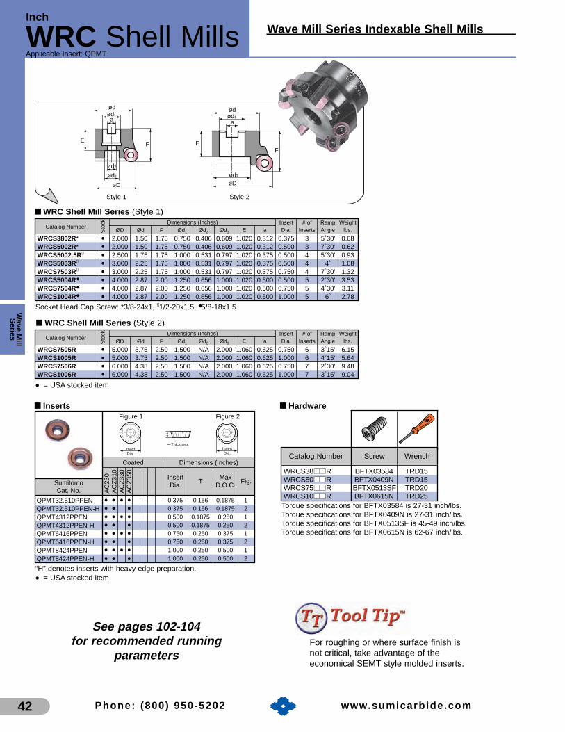
■ WRC Shell Mill Series (Style 1)
øD
ød1
a
ød3
ød
ød2
FE
øD
ød1
a
ød3
ød
FE
■ WRC Shell Mill Series (Style 2)
Wave M
illS
eries
42 Phone: (800) 950-5202 www.sumicarb ide.com
Style 1 Style 2
Applicable Insert: QPMT
Catalog NumberInsert # of Ramp Weight
ØD Ød F Ød1 Ød2 Ød3 E a Dia. Inserts Angle lbs.Dimensions (Inches)
Sto
ck
WRCS3802R* • 2.000 1.50 1.75 0.750 0.406 0.609 1.020 0.312 0.375 3 5˚30’ 0.68WRCS5002R* • 2.000 1.50 1.75 0.750 0.406 0.609 1.020 0.312 0.500 3 7˚30’ 0.62WRCS5002.5R✝ • 2.500 1.75 1.75 1.000 0.531 0.797 1.020 0.375 0.500 4 5˚30’ 0.93WRCS5003R✝ • 3.000 2.25 1.75 1.000 0.531 0.797 1.020 0.375 0.500 4 4˚ 1.68WRCS7503R✝ • 3.000 2.25 1.75 1.000 0.531 0.797 1.020 0.375 0.750 4 7˚30’ 1.32WRCS5004R◆ • 4.000 2.87 2.00 1.250 0.656 1.000 1.020 0.500 0.500 5 2˚30’ 3.53WRCS7504R◆ • 4.000 2.87 2.00 1.250 0.656 1.000 1.020 0.500 0.750 5 4˚30’ 3.11WRCS1004R◆ • 4.000 2.87 2.00 1.250 0.656 1.000 1.020 0.500 1.000 5 6˚ 2.78
Catalog NumberInsert # of Ramp Weight
ØD Ød F Ød1 Ød2 Ød3 E a Dia. Inserts Angle lbs.Dimensions (Inches)
Sto
ck
WRCS7505R • 5.000 3.75 2.50 1.500 N/A 2.000 1.060 0.625 0.750 6 3˚15’ 6.15WRCS1005R • 5.000 3.75 2.50 1.500 N/A 2.000 1.060 0.625 1.000 6 4˚15’ 5.64WRCS7506R • 6.000 4.38 2.50 1.500 N/A 2.000 1.060 0.625 0.750 7 2˚30’ 9.48WRCS1006R • 6.000 4.38 2.50 1.500 N/A 2.000 1.060 0.625 1.000 7 3˚15’ 9.04
Torque specifications for BFTX03584 is 27-31 inch/lbs.Torque specifications for BFTX0409N is 27-31 inch/lbs.Torque specifications for BFTX0513SF is 45-49 inch/lbs.Torque specifications for BFTX0615N is 62-67 inch/lbs.
■ Hardware
WRCS38■■■■R BFTX03584 TRD15WRCS50■■■■R BFTX0409N TRD15WRCS75■■■■R BFTX0513SF TRD20WRCS10■■■■R BFTX0615N TRD25
Catalog Number Screw Wrench
See pages 102-104for recommended running
parameters
Inch
WRC Shell Mills Wave Mill Series Indexable Shell Mills
• = USA stocked item
■ Inserts
Coated
Sumitomo Cat. No.
Dimensions (Inches)
AC
230
AC
Z31
0A
CZ
330
AC
Z35
0
• • • • • • •• • • •• • •• • • •• • •• • • •• • •
“H” denotes inserts with heavy edge preparation.
• = USA stocked item
InsertDia.
TMax
D.O.C.Fig.
0.375 0.156 0.1875 10.375 0.156 0.1875 20.500 0.1875 0.250 10.500 0.1875 0.250 20.750 0.250 0.375 10.750 0.250 0.375 21.000 0.250 0.500 11.000 0.250 0.500 2
QPMT32.510PPENQPMT32.510PPEN-HQPMT4312PPENQPMT4312PPEN-HQPMT6416PPENQPMT6416PPEN-HQPMT8424PPENQPMT8424PPEN-H
ThicknessInsertDia.
Figure 1
InsertDia.
Figure 2
For roughing or where surface finish isnot critical, take advantage of theeconomical SEMT style molded inserts.
Socket Head Cap Screw: *3/8-24x1, ✝1/2-20x1.5, ◆5/8-18x1.5

Wav
e M
illS
erie
s
43Phone: (800) 950-5202 www.sumicarb ide.com
Wave Mill Series Indexable Shell Mills
■ WFMC 400 and 500 Series
Inch
WFM400 & 500Applicable Insert: XDMT
Catalog Number# of Weight
Fig. I.C.D D1 F d a b E Teeth lbs.
Dimensions (Inches)
Sto
ck
WFMC403R • 3 2.165 1.969 1.000 0.374 0.252 1.000 4 1.98 1 0.500WFMC404R • 4 2.756 2.362 1.500 0.626 0.406 1.500 5 3.52 2 0.500WFMC405R • 5 3.150 2.362 1.500 0.626 0.406 1.500 6 5.72 2 0.500WFMC406R • 6 3.937 2.362 2.000 0.750 0.437 1.500 8 9.24 2 0.500WFMC408R • 8 5.906 2.362 2.500 1.000 0.551 1.380 10 17.60 3 0.500WFMC503R • 3 2.165 1.969 1.000 0.374 0.252 1.000 4 1.98 1 0.625WFMC504R • 4 2.756 2.362 1.500 0.626 0.406 1.500 5 3.52 2 0.625WFMC505R • 5 3.150 2.362 1.500 0.626 0.406 1.500 6 5.72 2 0.625WFMC506R • 6 3.937 2.362 2.000 0.750 0.437 1.500 8 9.24 2 0.625WFMC508R • 8 5.906 2.362 2.500 1.000 0.551 1.380 10 17.60 3 0.625
■ WFMF 400 and 500 Series
Catalog Number# of Weight
Fig. I.C.D D1 F d a b E Teeth lbs.
Dimensions (Inches)
Sto
ck
WFMF403R • 3 2.165 1.969 1.000 0.374 0.252 1.000 6 1.76 1 0.500WFMF404R • 4 2.756 2.362 1.500 0.626 0.406 1.500 7 3.30 2 0.500WFMF405R • 5 3.150 2.362 1.500 0.626 0.406 1.500 8 5.50 2 0.500WFMF406R • 6 3.937 2.362 2.000 0.750 0.437 1.500 10 8.80 2 0.500WFMF408R • 8 5.906 2.362 2.500 1.000 0.551 1.380 12 17.38 3 0.500WFMF503R • 3 2.165 1.969 1.000 0.374 0.252 1.000 6 1.76 1 0.625WFMF504R • 4 2.756 2.362 1.500 0.626 0.406 1.500 7 3.30 2 0.625WFMF505R • 5 3.150 2.362 1.500 0.626 0.406 1.500 8 5.50 2 0.625WFMF506R • 6 3.937 2.362 2.000 0.750 0.437 1.500 10 8.80 2 0.625WFMF508R • 8 5.906 2.362 2.500 1.000 0.551 1.380 12 17.38 3 0.625
øD1
øda
E
b
F
øD
øD1
øda
b
E
F
øD
øD1
øda
øD
F
Eb
Configuration
Fig. 1 Fig. 2 Fig. 3
DØ
Lead Angle: 0˚Axial Rake Angle: +8˚~ +6˚Radial Rake Angle: +10˚
■ Inserts
Sumitomo Cat. No.
• • • • •• • • • •
XDMT120408PDENXDMT150408PDEN
R
0.500 0.1875 0.0310.625 0.1875 0.031
IC
R
15°
T
I.C. T
Dimensions (Inches)UncoatedCoated
AC
230
AC
Z31
0A
CZ
330
AC
Z35
0
G10
E
■ Hardware
WFM■■40■■R WFMS4R BFTX0414 BT0506 TRD20 TH025WFM■■50■■R WFMS5R BFTX0515N BT0506 TRD20 TH025
Catalog Number SeatInsert Set
Wrench WrenchScrew Screw
See pages 102-104for recommended running
parameters
■ Features and Benefits• Available in both coarse and fine pitch,
and 5/8 and 1/2 inch insert sizes.
• Highly accurate 90 degree shoulder cutting.
• Steel insert seats allow cutter rebuilding in the event of a crash.
• Efficient positive rake design requires low amounts of horsepower and produces minimum workpiece stresses.
• Large flute relief promotes excellent chip evacuation.
• = USA stocked item
• = USA stocked item
• = USA stocked item

SumiMill
Spider Mill
Wave M
illS
eries
44
High Productivity Cast Iron MillingCutter With Eight Cutting Edges
Applicable Insert: SNEX
Phone: (800) 950-5202 www.sumicarb ide.com
■ Features and Benefits
• Double negative milling cutter with positive cutting insert geometry
• High productivity shell mill for gray cast iron and ductile iron face milling
• Eight (8) cutting edges per insert
• Available in the new grades ACK100 and ACK200
• Unique positive chipbreaker insert provides less cutting force, more productivity and longer tool life
R
TI.C.
F
E
aød1
ød
ød3
øD
ød2
F
E
aød1
ød
ød3
øD
■ Hardware
Applicable Cutter Insert Screw
SDP5■■000R BFTX0513N
Wrench
TTX20
Torque specifications for BFTX0513N is 45-49 in/lbs.
Figure 1 Figure 2
CVD Coated
Sumitomo Cat. No.
I.C. T R
Dimensions (Inches)
AC
K10
0A
CK
200
• •SNEX156612DP 0.625 0.266 0.047
■ Inserts
• = USA stocked item
• = USA stocked item
■ Spider Mill Availability
Sumitomo Cat. No. StatusDimensions (Inch)
øD ød F ød1 ød2 ød3 E a I.C. Pitch Fig.SDP53000R • 3.000” 2.250” 1.750” 1.000” 0.531” 0.797” 1.020” 0.385” 0.625” 5 1SDP54000R • 4.000” 2.756” 2.000” 1.250” 0.656” 1.030” 1.090” 0.515” 0.625” 7 1SDP55000R • 5.000” 3.750” 2.500” 1.500” NA 2.000” 1.060” 0.635” 0.625” 8 2SDP56000R • 6.000” 4.380” 2.500” 1.500” NA 2.000” 1.060” 0.635” 0.625” 10 2
See pages 102-104for recommended running
parameters

Metal Slash MillHigh Feed Milling Cutter
Wav
e M
illS
erie
s
45Phone: (800) 950-5202 www.sumicarb ide.com
High Feed Milling Cutter
MS Mill SeriesApplicable Insert: SDMW, SDEW
■ Features and Benefits
• Screw-on insert assembly
• U.S. stock standard bodies available in 2.000” - 4.000” diametersWorldwide stock includes 63.0 mm - 125 mm
• High feed rates (Maximum feed rate = 0.078” IPT) result in high productivity milling
• Four corner insert design yields low tooling costs per part
• Unique design directs cutting forces into the machine spindle to facilitate high feed rates even in low rigidity conditions
• Insert grades available for carbon steel, stainless steel, cast iron, & die steel
■ Hardware
Applicable Cutter Insert Screw
MS 1400 series BFTX0513N
Wrench
TTX20
Torque specifications for BFTX0513N is 45-49 in/lbs.
Coated
Sumitomo Cat. No.
T R2 R5 Fig.
Dimensions (Inches)
CS
3000
AC
Z31
0A
CZ
330
AC
K20
0A
CK
300
AC
P20
0A
CP
300
• • • O O O O
★ ★ ★ ★ ★ ★ ★
SDMW1406ZDTRSDEW1406ZDTR
0.551 0.236 0.079 0.197 30.551 0.236 0.079 0.197 4
■ Inserts
SDEW = Ground tolerance inserts
• = USA stocked item★ = Worldwide Warehouse itemO = New product arrives 2nd quarter 2007
■ MS Mill Availability
Sumitomo Cat. No. Stock Fig.Dimensions (Inch / mm)D D1 D2 D3 F d a b E
MS14020SR • 2.000 1.500 0.609 0.406 1.750 0.750 0.319 0.190 1.020 4 1MS14025SR • 2.500 1.750 0.797 0.531 1.750 1.000 0.375 0.220 1.020 4 1MS14030R • 3.000 2.250 0.797 0.531 1.750 1.000 0.375 0.220 1.020 5 1MS14040R • 4.000 2.870 1.000 0.656 2.000 1.250 0.500 0.280 1.020 6 1MS14063RS ★ 63.0 59.0 18.0 11.0 40.0 22.0 10.4 6.3 26.0 4 1MS14080R ★ 80.0 60.0 20.0 13.0 50.0 25.4 9.5 6.0 31.0 5 1MS14100R ★ 100.0 70.0 46.0 – 50.0 31.8 12.7 8.0 32.0 6 2MS14125R ★ 125.0 80.0 56.0 – 63.0 38.1 15.9 10.0 38.0 7 2
Fig 3 Fig 4
I.C. 0.003"
15˚
15˚
R2R2
R5 R5
ThicknessThickness+-
I.C. 0.001"+-
øD1
øD3
øD2
øD2
øDøD
øda
øD1
øda
E
F F
b
E
b
Fig 1 Fig 2
• = USA stocked item★ = Worldwide Warehouse item
I.C.
No. ofTeeth
See pages 102-104for recommended running
parameters

UFO “400” EndmillsUltra High Positive Endmill
Wave M
illS
eries
46 Phone: (800) 950-5202 www.sumicarb ide.com
Indexable Endmills
UFO SeriesApplicable Insert: SFEN, SFKN, SFKR, UW
UFO 420EX-R8UFO 425EX-R8UFO 430EX-R8
øD øD1
Max.D.O.C.
Axial Rake
No. ofTeeth
2.0002.5003.000
•••
3.0003.4063.953
+27°
Radial Rake
-7°
LeadAngle
45°
InsertI.C.
.500456
.197
Dimensions (Inches)
■ BODY - BRIDGEPORT SHANK
.949
1.756
5.8864.311
3.0932.875
1.250 DIA
øD1 øD
45°
InsertType
SFKN
Coated
Sumitomo Cat. No.
I.C. TFacetWidth
Figure
Cermet Uncoated Dimensions (Inches)
AC
Z31
0A
CZ
330
AC
Z35
0A
C23
0A
C32
5A
C21
1E
H20
ZK
245R
2A
CK
200
AC
K30
0A
CP
100
AC
P20
0A
CP
300
T25
0AT
110A
A30
NG
10E
H10
EH
1
•• • ▲ ▲ ★ O O • •
• ▲ • • O O •▲
• •
SFEN12T3AZFNSFKN12T3AZTNSFKN12T3AZFNSFKR12T3AZENUW12500R/L 0.500 0.156 0.218 2
0.500 0.156 0.088 1
Figure 1 Figure 2
I.C.25°
T
.787
■ Inserts
■ Hardware
Locator Seat *InsertClamp
**LocatorClamp
ClampScrew
UF4KR UF4SR UFTWR UFKWR WB715TUFO4 ■■ ■■ EXR8
* Torque specifications for insert clamp screw=49-53 in/lbs.**Torque specifications for locator clamp screws=62-66 in/lbs.
Wrench
TT25
Catalog Number
■ UFO End Mill SeriesCatalogNumber
Stock
TN = “T” land FN = honed
• = USA stocked item★ = Worldwide Warehouse item O = New product arrives 2nd quarter 2007▲ = USA limited availability item
See pages 102-104for recommended running
parameters
• = USA stocked item

UFO “400” Face MillsUltra High Positive Face Mill
Wav
e M
illS
erie
s
47Phone: (800) 950-5202 www.sumicarb ide.com
Indexable Shell Mills
UFO SeriesApplicable Insert: SFEN, SFKN, SFKR, UW
*Torque specifications for insert clamp screw=49-53 in/lbs.**Torque specifications for locator clamp screws=62-66 in/lbs.
Clampscrew
Clampscrew
Insert clamp
Locatorclamp
Seat
Insert
Locator
3.0004.0005.0006.0008.000
10.00012.000
3.9454.8985.8436.8348.819
10.80312.756
1.9692.3622.3622.3622.3622.7562.756
2.3622.9532.9533.9375.1187.0879.449
1.0001.5001.5002.0002.5002.5002.500
.375
.625
.625
.7501.0001.0001.000
.250
.405
.405
.437
.531
.531
.531
.197
68
1012162024
1.0001.4961.4961.4961.4961.5751.575
1/2
1
2
3
Dimensions (Inches)Stock
DR L D1 F aD2 d b ENo. ofTeeth Fig. I.C.Max.
D.O.C.
UFOF 403R/LUFOF 404R/L*UFOF 405R/L*UFOF 406R/L**UFOF 408R/LUFOF 410R/LUFOF 412R/L
■ UFO Fine Pitch Face Mill Series
MaxD.O.C.
45°
øD
Lead Angle:Axial Rake Angle:Radial Rake Angle:
45°+27°
-7°øD1
øD2
ø7.0ø4.0
øda
ø.7087 ø.8661
F
b E
øD
b
F
øD
øD1
Eøda
øD2
ø4.0ø.7087
Fig. 2 Fig. 3
■ Hardware
Locator Seat *InsertClamp
**LocatorClamp
ClampScrew
UF4KR UF4SR UFTWR UFKWRWB715T*
UFOF4 ■■ ■■ R
Wrench
TT25UF4KL
UF4SLSUFTWL UFKWL
UFOF402L
UF4SLUFOF4 ■■ ■■ L
Catalog Number
CatalogNumber
*Requires BFX3/4x16 arbor screw**Requires BFX1x14 arbor screw
• = USA stocked item
•••••
•
See pages 102-104for recommended running
parameters
Coated
Sumitomo Cat. No.
I.C. TFacetWidth
Figure
Cermet Uncoated Dimensions (Inches)
AC
Z31
0A
CZ
330
AC
Z35
0A
C23
0A
C32
5A
C21
1E
H20
ZK
245R
2A
CK
200
AC
K30
0A
CP
100
AC
P20
0A
CP
300
T25
0AT
110A
A30
NG
10E
H10
EH
1
•• • ▲ ▲ ★ O O • •
• ▲ • • O O •▲
• •
SFEN12T3AZFNSFKN12T3AZTNSFKN12T3AZFNSFKR12T3AZENUW12500R/L 0.500 0.156 0.218 2
0.500 0.156 0.088 1
Figure 1 Figure 2
I.C.25°
T
.787
■ Inserts
TN = “T” land FN = honed
• = USA stocked item★ = Worldwide Warehouse itemO = New product arrives 2nd quarter 2007▲ = USA limited availability item
E
F
øD
øD1
øD2
ødb a
Fig. 1

Indexable Shell Mills
UFO SeriesApplicable Insert: SFEN, SFKN, SFKR, UW
Wave M
illS
eries
48
UFO “400 & 500” Face MillsUltra High Positive Face Mill
Phone: (800) 950-5202 www.sumicarb ide.com
Clampscrew
Clampscrew
Insert clamp
Locatorclamp
Seat
Insert
Locator
2.0003.0004.0005.0006.0008.000
10.00012.0003.0004.0005.0006.0008.000
10.00012.000
2.9923.9454.8985.8436.8348.819
10.80312.7563.9454.8985.8436.8348.819
10.80312.756
1.9691.9692.3622.3622.3622.3622.7562.7561.9692.3622.3622.3622.3622.7562.756
1.7722.3622.9532.9533.9375.1187.0879.4492.3622.9532.9533.9375.1187.0879.449
.7501.0001.5001.5002.0002.5002.5002.5001.0001.5001.5002.0002.5002.5002.500
.321
.375
.625
.625
.7501.0001.0001.000.375.625.625.750
1.0001.0001.000
.200
.250
.405
.405
.437
.531
.531
.531
.250
.405
.405
.437
.531
.531
.531
.197
.276
44568
1012144568
101214
.7871.0001.4961.4961.4961.4961.5751.5751.0001.4961.4961.4961.4961.5751.575
1/2
5/8
1
2
3
1
2
3
Dimensions (Inches)Stock
DR L D1 F aD2 d b ENo. ofTeeth Fig. I.C.Max.
D.O.C.
UFO 402R/LUFO 403R/LUFO 404R/L*UFO 405R/L*UFO 406R/L**UFO 408R/LUFO 410R/LUFO 412R/LUFO 503R/LUFO 504R/L*UFO 505R/L*UFO 506R/L**UFO 508R/LUFO 510R/LUFO 512R/L
■ UFO Coarse Pitch Face Mill Series
MaxD.O.C.
45°
øD
*Approach Angle:*Axial Rake Angle:*Radial Rake Angle:
45°+27°
-7°
b
F
øD
øD1
Eøda
øD2
ø4.0ø.7087
F
ødab
EE
øD1
øD2
F
øDøD
øD1
øD2
ødb a
Fig. 1 Fig. 2 Fig. 3
*Requires BFX3/4x16 arbor screw **Requires BFX1x14 arbor screw • = USA stocked item
CatalogNumber
■ Hardware
Locator Seat *InsertClamp
**LocatorClamp
ClampScrew
UF4KRUF4SRS
UFTWR UFKWR WB715TUFO402R
*Torque specifications for insert clamp screw=49-53 in/lbs.**Torque specifications for locator clamp screws=62-66 in/lbs.
Wrench
TT25UF4SRUFO4 ■■ ■■ R
UF4KLUF4SLS
UFTWL UFKWL WB715TUFO402L
TT25UF4SLUFO4 ■■ ■■ L
UF5KR UF5SR UFTWR UFKWR WB715TUFO5 ■■ ■■ R TT25UF5KL UF5SL UFTWL UFKWL WB715TUFO5 ■■ ■■ L TT25
Catalog Number
Coated
Sumitomo Cat. No.
I.C. TFacetWidth
Figure
Cermet Uncoated Dimensions (Inches)
AC
Z31
0A
CZ
330
AC
Z35
0A
C23
0A
C32
5A
C21
1E
H20
ZK
245R
2A
CK
200
AC
K30
0A
CP
100
AC
P20
0A
CP
300
T25
0AT
110A
A30
NG
10E
H10
EE
H20
H1
SFEN12T3AZFNSFKN12T3AZTNSFKN12T3AZFNSFKR12T3AZENSFKN1504AZTNSFKN1504AZFNUW12500R/LUW15500R/L
0.625 0.1875
0.500 0.156 0.2180.625 0.1875 0.250
1
0.088
0.500 0.156 0.088
2
Figure 1 Figure 2
I.C.25°
T
.787
■ Inserts
TN = “T” land FN = honed O = New product arrives 2nd quarter 2007
• = USA stocked item ▲ = USA limited availability item ★ = Worldwide Warehouse item
••••••••••••
••
•
•••
•
See pages 102-104for recommended
running parameters
•• • ▲ ▲ ★ O O • •
• ▲ • • O O • ▲
• • ▲ ▲ O O •• ▲ • O • •
• •• •

49Phone: (800) 950-5202 www.sumicarb ide.com
UFOR “600” Face MillsUltra High Positive Face Mill
Wav
e M
illS
erie
s
Indexable Shell Mills
UFO SeriesApplicable Insert: RGMN
aødøD2
øD1
b
E
øD
F
aødøD2
øD1
b
E F
øD øD
øD2
øD1
aød
ø 4.0
ø.5118ø.7874
øD
øD2
øD1
aød
ø 4.0
ø.7087
ø7.0
ø.8661
b
E
b
E
ø.7087
F F
Locator
Insert Clamp
Insert
LocatorScrew
InsertScrew
34568
1012
3.8074.7485.7126.6738.630
10.60212.587
1.9692.3622.3622.3622.3622.7562.756
2.3622.9532.9533.9375.1187.0879.449
1.0001.5001.5002.0002.5002.5002.500
.375
.625
.625
.7501.0001.0001.000
.250
.405
.405
.437
.531
.531
.531
.375
4568
101214
1.0001.4961.4961.4961.4961.5751.575
D D1 F aD2 d b ENo. ofTeeth Fig.Max.
D.O.C.
UFOR 603RUFOR 604RUFOR 605RUFOR 606RUFOR 608RUFOR 610RUFOR 612R
Dimensions (Inches)
Fig. 1 Fig. 2 Fig. 3 Fig. 4
.MaxD.O.C.
øD
Axial Rake Angle: +25˚Radial Rake Angle: +10˚
CatalogNumber
Stock
■ UFOR Face Mill Series
Note: use "SNS" for Steel applicationsuse "SNI" for Inconel applicationsuse "SNT" for Titanium applications
• = USA stocked item
1
2
3
4
*Torque specifications for insert clamp screw=58-62 in/lbs.**Torque specifications for locator clamp screws=35-40 in/lbs.
Sumitomo Cat. No.
InsertDia.
T
Dimensions
AC
325
EH
20Z
•
•
•
RGMN2004SNSEdge prep = 0.008” x -30o
RGMN2004SNIEdge prep = 0.002” x -15o
RGMN2004SNTEdge prep = 0.002” x -30o
0.7874(20 mm)
0.1875
30°InsertDia.
T
■ Inserts
■ Hardware
Locator LocatorScrew**
InsertScrew* Wrench
GRKR GRWR BH0410T WB8-20TH040
TRD15UFOR6 ■■ ■■ R
Catalog Number InsertClamp
Coated
•••
••
See pages 102-104for recommended running
parameters
• = USA stocked item

Indexable Endmills
sumiMill SeriesApplicable Insert: TECN, TEEN, NF-TEEN, TEKN
Wave M
illS
eries
50
CHE Shoulder MillsPositive Shoulder Mill
Phone: (800) 950-5202 www.sumicarb ide.com
dD
L
d
D
L
l1
l2 l3
l1
l2 l3
Figure 1 Figure 2
I.C.20°
T
I.C.
1.2501.5002.000
.949
.949
.949
5.8755.8755.875
.500
.500
.750
2.7812.7812.781
3.0933.0933.093
223
15°15°15°
–2°–1°2°
0°0°0°
.375
.500
.500
Dimensions (Inches) Cutting Angle
Nom.Dia.
ShankDia.
OverallLength
Cutting EdgeLength
ThicknessShankLength
D d L l1 l2 l3
Axial
No. of
Teeth Radial Lead
InsertI.C.
CHE3-1250RR8CHE3-1500RR8CHE4-2000RR8
CatalogNumber
Stock
■ CHE Bridgeport Shank Series
■ Hardware
Locator Clamp LocatorScrew
ClampScrew
RetainingRing
– CCH5R – BHE0510 ER04CHE3-1 ■■ ■■ ■■ RR8
ClampWrench
LocatorWrench
– LH030
CEWR FBH0512 WB8R-16T – TT27 TH030LCE4RCHE4-2000RR8
Catalog Number
Coated
Sumitomo Cat. No.
I.C. T Figure
Cermet Uncoated PCD Dimensions (Inches)
AC
230
AC
325
AC
211
T25
0A
A30
NG
10E
H1
DA
2200
DA
150
•• • •
•
••
• ••
• •• • • •
TECN32RTEEN32RNF-TEEN32RTEKN32RTEKN32TRTECN43RTEEN43RNF-TEEN43RTEKN43RTEKN43TR
0.375 0.125 10.375 0.125 20.375 0.125 20.375 0.125 10.375 0.125 10.500 0.1875 10.500 0.1875 20.500 0.1875 20.500 0.1875 10.500 0.1875 1
■ Inserts
“T” denotes inserts with a T-Land
• = USA stocked item
▲
▲
▲
See pages 102-104for recommended running
parameters
▲ = USA limited availability item

CHE Shoulder MillsPositive Shoulder Mill
51
Indexable Endmills
sumiMill SeriesApplicable Insert: TECN, TEEN, NF-TEEN, TEKN
Phone: (800) 950-5202 www.sumicarb ide.com
Wav
e M
illS
erie
s
dD
L
d
D
L
l1
l2 l3
l1
l2 l3
Figure 1 Figure 2
I.C.20°
T
I.C.
Coated
Sumitomo Cat. No.
I.C. T Figure
Cermet Uncoated PCD Dimensions (Inches)
AC
230
AC
325
AC
211
T25
0A
A30
NG
10E
H1
DA
2200
DA
150
•• • •
•
•▲
• ••
• •• • • •
TECN32RTEEN32RNF-TEEN32RTEKN32RTEKN32TRTECN43RTEEN43RNF-TEEN43RTEKN43RTEKN43TR
0.375 0.125 10.375 0.125 20.375 0.125 20.375 0.125 10.375 0.125 10.500 0.1875 10.500 0.1875 20.500 0.1875 20.500 0.1875 10.500 0.1875 1
■ Inserts
“T” denotes inserts with a T-Land
• = USA stocked item▲ = USA limited availability item
.625
.750
.8751.0001.1251.2501.5002.000
.625
.750
.7501.00010001.2501.2501.250
3.4843.4843.6874.3754.3754.5624.5624.562
.312312 312 312 312 .500.500.750
1.0001.1871.1871.3751.3751.5621.5621.562
2.4842.5002.5003.0003.000 3.000 3.000 3.000
11222223
6°8°
12°15°15°15°15°15°
–3°–2°–1°–1°0°
–2°–1°2°
0°0°0°0°0°0°0°0°
.250
.250
.250
.250
.250
.375
.375
.500
Dimensions (Inches) Cutting Angle
Nom.Dia.
ShankDia.
OverallLength
Cutting EdgeLength
Thickness ShankLength
D d L l1 l2 l3
Axial Radial Lead
InsertI.C.
CHE2-0625RWCHE2-0750RWCHE2-0875RWCHE2-1000RWCHE2-1125RWCHE3-1250RWCHE3-1500RWCHE4-2000RW
No. of
Teeth
CatalogNumber
Stock
■ CHE Weldon Shank Series
■ Hardware
Locator Clamp LocatorScrew
ClampScrew
RetainingRing
– CCH4R – BHE0407 ER03CHE2- ■■ ■■ ■■ ■■ RW
ClampWrench
LocatorWrench
– TH025
CCH5R
CEWR
–
FBH0512
BHE0510
WB8R-16T
ER04
–
–
TT27
LH030
TH030
–
LCE4R
CHE3- 1 ■■ ■■ ■■ RW
CHE4- 2000RW
Catalog Number
▲
▲
▲
▲
▲
▲
▲
▲
See pages 102-104for recommended running
parameters
▲ = USA limited availability item

Indexable Shell Mills
sumiMill SeriesApplicable Insert: SDC, NF-SDC, APW
Wave M
illS
eries
52
APG 400 Face MillsHigh Positive Face Mill
Phone: (800) 950-5202 www.sumicarb ide.com
Figure 1 Figure 2 Figure 3
15°
T
FW
I.C.
65°
TI.C.
15˚
15˚
I.C. T
25°
MaxD.O.C.
øD
*Lead Angle:*Axial Rake Angle:*Radial Rake Angle:
25°+18°
-2°
E
.512.787
D
F
ad
D1
E
D
F
ad
b
D1
D
E
b ad
.709
F
32
1.024
4.00
D1
b
Fig. 1 Fig. 2 Fig. 3
Insert
LocatorCap Screw
Double Screw Clamp
3.0004.0005.0006.0008.000
3.4134.3815.3606.3468.327
.375
.625
.625
.7501.000
1.9692.3622.3622.3622.756
1.0001.5001.5002.0002.500
.250
.406
.406
.437
.562
1.0001.4961.4961.4961.496
5568
10
.275
.275
.275
.275
.275
12223
.500
.500
.500
.500
.500
Dimensions (Inches)
D D1 a EF d bNo. ofTeeth
Max.D.O.C. Fig. I.C.
■ APG Face Mill Series
APG403RAPG404R*APG405R*APG406R**APG408R
CatalogNumber
Stock
■ Hardware
Locator ClampBolt
CapScrew Wrench
LAP40RL ATW45RL
WB820
WB824T
WB824TL
BXF0520RL
TH040
TT27
APG403R
APG404R
APG405R
APG406R
APG408R
Catalog Number InsertClamp
*Requires BFX3/4x16 arbor screw**Requires BFX1x14 arbor screw
• = USA stocked item▲ = USA limited availability item
Coated
Sumitomo Cat. No.
I.C. TFacetWidth
Figure
Uncoated PCD Dimensions (Inches)
AC
325
A30
NH
1
DA
2200
DA
150
DA
200
• • •• •
•• •
SDC42RSDC42TRSDC53RNF-SDC42RAPW4R
■ Inserts
“T” denotes inserts with T-Land
• = USA stocked item
0.500 0.125 0.0938 10.500 0.125 0.0938 10.625 0.1875 0.0938 10.500 0.125 0.0938 20.500 0.125 0.193 3
••▲
••
See pages 102-104for recommended running
parameters

DNF Face Mill SeriesDouble Negative Face Mill
Wav
e M
illS
erie
s
53
Indexable Shell Mills
sumiMill SeriesApplicable Insert: CSNH, SNG, SNMN, NW
Phone: (800) 950-5202 www.sumicarb ide.com
øD1
øD2
øD
øda
ø13ø20
E F
b
øD1
øD2
ø56øD
øda
E F
b
øD1
øD2
ø101.6
øD
øda ø18
ø26
E F
b
øD1
øD2
ø177.8ø101.6
øD
øda ø18 ø22
ø26 ø32
E
F
b
Cap ScrewBX0510
InsertDouble ScrewWB8-30T Clamp
WrenchTT27LH040
Locator
3.1503.9374.9216.300
3.7804.5675.5516.930
1.9692.3622.3622.362
2.3622.9532.9533.937
1.0001.2501.5002.000
0.3750.5000.6250.750
0.2360.3150.3940.433
.250
68
1012
0.9851.2601.4961.496
D D1 F aD2 d b ENo. ofTeeth Fig.Max.
D.O.C.
DNF 4080RDNF 4100RDNF 4125R*DNF 4160R**
Dimensions (Inches)
øD
Lead Angle: 25˚Axial Rake Angle: -5˚Radial Rake Angle: -6˚
■ DNF Face Mill Series
1234
Weight(kg)
1.83.04.36.8
CatalogNumber
Stock
■ Hardware
Locator LocatorClamp
InsertScrew* Wrench
LNF40R FTW40R BX0510 WB830TDNF ■■ ■■ ■■ ■■ R
Catalog Number InsertClamp
Torque specifications for locator clamp (WB830T)= 71-75 in/lbs.Torque specifications for insert clamp (WB830T)= 57-62 in/lbs.
TT27
LH040
*Requires BFX3/4x16 arbor screw**Requires BFX1x14 arbor screw▲ = USA limited availability item
Coated
Sumitomo Cat. No.
Cermet Uncoated Ceramic Dimensions (Inches)
Figure 2 Figure 3
AC
Z31
0A
C32
5
T25
0A
H10
E
NS
30N
S26
0
•• •
•••
•• • •
••
CSNH43MSNG432SNG433SNG434SNG438SNMN432SNMN433SNMN434NW100
Figure 1
■ Inserts
T RFacetWidth
Figure
0.500 0.189
0.500 0.1875
0.500 0.1875
– 0.197
0.500 1–0.03120.04690.06250.12500.03120.04690.0625
–
–
–
–
I.C.
2
2
3
I.C. T
FW
TI.C.
R
T
DNF Milling Cutterj Features and Benefits
• Double negative rake anglesprovide high cutting edge strength
• Up to eight indexes per cutter load• NS260 ceramic inserts are an
economical option for the high speed milling of gray cast iron
Fig. 1 Fig. 2 Fig. 3 Fig. 4
▲
▲
▲
▲
See pages 102-104for recommended running
parameters
• = USA stocked item
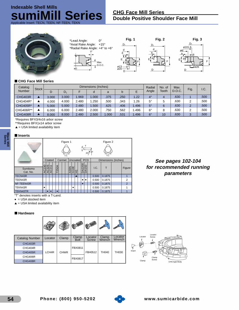
Indexable Shell Mills
sumiMill SeriesApplicable Insert: TECN, TEEN, NF-TEEN, TEKN
Wave M
illS
eries
54
CHG Face Mill SeriesDouble Positive Shoulder Face Mill
Phone: (800) 950-5202 www.sumicarb ide.com
■ CHG Face Mill Series
LocatorLocatorScrew
Insert
Clamp
ClampScrew
CHG-type Body
3.0004.0005.0006.0008.000
3.0004.0005.0006.0008.000
.375
.500
.625
.7501.000
1.9692.4802.4802.4802.480
1.0001.2501.5002.0002.500
.250
.343
.406
.562
.531
1.221.26
1.4961.4961.496
4568
10
4°5°5°6°6°
.630
.630
.630
.630
.630
12223
.500
.500
.500
.500
.500
Dimensions (Inches)
D D1 a EF d bNo. ofTeeth
RadialAngle
Max.D.O.C. Fig. I.C.
CHG403RCHG404R*CHG405R*CHG406R**CHG408R
Max.D.O.C.
øD
0°
*Lead Angle:*Axial Rake Angle:*Radial Rake Angle:
0°+15°+4° to +6°
F
da
E
ø13ø20
D
D1 D1
da
EF
D
b
D1
ø101.6
F
D
E b
aød
ø26
ø18
Fig. 1 Fig. 2 Fig. 3
b
*Requires BFX3/4x16 arbor screw**Requires BFX1x14 arbor screw▲ = USA limited availability item
CatalogNumber
Stock
■ Hardware
Locator Clamp ClampBolt
LocatorScrew
ClampWrench
CHG403R
LocatorWrench
CHG404R
CHWR
FBX0811
FBH0512 TH030TH040LCH4RCHG405R
FBX0817CHG406R
CHG408R
Catalog Number
Figure 1 Figure 2
I.C.20°
T
I.C.
Coated
Sumitomo Cat. No.
I.C. T Figure
Cermet Uncoated PCD Dimensions (Inches)
AC
230
AC
325
AC
211
T25
0A
A30
NG
10E
H1
DA
2200
DA
150
▲
• ••
• •• • •
TECN43RTEEN43RNF-TEEN43RTEKN43RTEKN43TR
0.500 0.1875 10.500 0.1875 20.500 0.1875 20.500 0.1875 10.500 0.1875 1
■ Inserts
“T” denotes inserts with a T-Land.
• = USA stocked item▲ = USA limited availability item
▲
▲
▲
▲
▲
See pages 102-104for recommended running
parameters

CPG 400 & 500 Face Mill SeriesSquare Shoulder Face Mill
Wav
e M
illS
erie
s
55
Indexable Shell Mills
sumiMill SeriesApplicable Insert: TPCH, TPC, TPG, TPMN
Phone: (800) 950-5202 www.sumicarb ide.com
Figure 1 Figure 2 Figure 3
11°I.C.
T
11°I.C.
T
I.C.
R
11°
T
0°
MaxD.O.C.
øD
*Lead Angle:*Axial Rake Angle:*Radial Rake Angle:
0°+6°0°, 2° for5XX Series
D
E
ø13ø20
D
F
ad
D1
E
D
F
ad
b
D1
D
E
b ad
ø18
F
ø26
ø101.6D1
b
Fig. 1 Fig. 2 Fig. 3
Coated
Sumitomo Cat. No.
Cermet Uncoated Dimensions (Inches)
AC
230
AC
325
AC
211
EH
20Z
T25
0A
A30
NG
10E
NS
30
• •• • • •
• •• •
• •• • • •• • •••••• •• •
TPCH43RTPCH43TRTPC53P12RTPC53P12RATPG431TPG432TPG433TPG434TPG436TPMN431TPMN432TPMN433TPMN434
■ Inserts
T R FigureI.C.
■ CPG 400 & 500 Face Mill Series
3.1504.3314.9216.299
3.1504.3314.9216.299
0.3750.6250.6250.750
1.9692.3622.3622.362
1.0001 1/21.5002.000
0.2340.3900.3900.437
0.9841.7811.7811.781
568
10
.630
1
21/2
Dimensions (Inches)
D D1 a EF d bNo. ofTeeth
Max.D.O.C. Fig. I.C.
CPG03RCPG04R*CPG05R*CPG06R**
Double Screw
ClampInsert
Locator
Locator Bolt
4.0005.0006.0008.000
4.0005.0006.0008.000
0.6250.6250.7501.000
2.3622.3622.3622.362
1.5001.5002.0002.500
0.4060.4060.4370.531
1.7811.7811.7811.781
568
10
.700
1
2
3
5/8
CPG504R*CPG505R*CPG506R**CPG508R
*Requires BFX3/4x16 arbor screw**Requires BFX1x14 arbor screw▲ = USA limited availability item
0.500 0.1875 – 10.500 0.1875 – 10.625 0.1875 – 20.625 0.1875 – 20.500 0.0156 – 30.500 0.0312 – 30.500 0.0469 – 30.500 0.0625 – 30.500 0.0938 – 30.500 0.0156 – 30.500 0.0312 – 30.500 0.0469 – 30.500 0.0625 – 3
“T” denotes inserts with a T-Land.
• = USA stocked item
CatalogNumber
Stock
■ Hardware for 500 Series
Locator Clamp ClampBolt
LocatorClamp
BoltWrench
PTW50RCPG504R
Wrench
CPG505RLCP50R WB8-24T BH0408 TT27CPG506R TT25
PTW51RCPG508RCPG510R
Catalog Number
■ Hardware for 400 Series
Locator ClampBolt
LocatorBolt Wrench
LCP40R
PTW40R
PTW41RWB8-24T BX0510
CPG03RCPG04R
CPG05RCPG06R
Catalog Number Clamp
TT27
LH040
Ceramic
▲
▲
••▲
▲
••
See pages 102-104for recommended running
parameters

Indexable Shell Mills
sumiMill SeriesApplicable Insert: SPCH, SPG, SPMN, DPW
Wave M
illS
eries
56
DPG 400 Face Mill SeriesPositive Face Mill
Phone: (800) 950-5202 www.sumicarb ide.com
3.1254.5006.1258.000
10.00012.500
0.3750.6250.7501.0001.0001.000
1.9692.3622.3622.7562.7562.756
1.0001.5002.0002.0002.0002.000
0.2500.4060.4371.6251.6251.625
1.0001.5001.5001.5001.5751.575
458
101214
.445
1
2
3
1/2
Dimens
D D1 a EF d b
Max.D.O.C. Fig. I.C.
DPG403RDPG404R*DPG406R**DPG408RDPG410RDPG412R
■ DPG 400 Face Mill Series
Double Screw
DoubleScrew
InsertClamp
Locator
ClampInsert
15°
MaxD.O.C.
øD
*Lead Angle:*Axial Rake Angle:*Radial Rake Angle:
15°+8°
0°
3.544.846.578.30
10.2012.80
E
ø13ø20
D
F
ad
D1
E
D
F
ad
b
D1
D
E
b ad
ø18
F
32
ø26
ø101.6
D1
b
Fig. 1 Fig. 2 Fig. 3
*Requires BFX3/4x16 arbor screw**Requires BFX1x14 arbor screw
• = USA stocked item▲ = USA limited availability item
Dimensions (Inches)
D D1 a EF d bNo. ofTeeth
CatalogNumber
Stock
■ Inserts
Coated
Sumitomo Cat. No.
I.C. TFacetWidth
R Figure
Uncoated Ceramic Dimensions (Inches)
Figure 1 Figure 2 Figure 3
AC
Z31
0A
C23
0A
C32
5A
C21
1E
H20
ZA
30N
G10
E
NS
30N
S26
0
• •• • •
▲
• •• • • •• • •• •• •• • •• ••
•
SPCH42RSPCH42TRSPCH42TLSPG421SPG422SPG423SPG424SPMN421SPMN422SPMN423SPMN424DPW500R
0.500 0.125 0.125
0.01560.03120.04690.06250.01560.03120.04690.0625
0.480 0.126 0.126 N/A 3
0.500 0.125 N/A 2
1N/A
11°15°
T
I.C.
F
11°
T
I.C.
I.C.
11°
T
15°
“T” denotes inserts with a T-Land.
• = USA stocked item▲ = USA limited availability item
Torque specifications for locator clamp (WB830T)=71-75 in/lbs.Torque specifications for insert clamp (WB830T)=57-62 in/lbs.
■ Hardware
Locator InsertClamp
ClampBolt Wrench
GL40R
GLW40R GTW40R
GTW41R WB824TGLW41R
GTW42R WB830TGLW42R
WB830T
TT27
DPG403R
DPG404R
DPG406R
DPG408R
DPG410R
DPG412R
Catalog Number LocatorClamp
▲
••▲
••
See pages 102-104for recommended running
parameters

DPG 500 Face Mill SeriesPositive Face Mill
Wav
e M
illS
erie
s
57
Indexable Shell Mills
sumiMill SeriesApplicable Insert: SPCH, SPG, SPMN
Phone: (800) 950-5202 www.sumicarb ide.com
3.2504.5006.2508.000
10.00012.500
3.5404.8406.5708.300
10.20012.800
0.3750.6250.7500.7501.0001.000
1.9882.3822.3822.7762.7762.776
1.0001.5002.0002.0002.0002.000
0.2500.4060.4371.6251.6251.625
1.0001.5001.5001.5001.5751.575
458
101214
.563
Dimensions (Inches)
D D1 a EF d bNo. ofTeeth
Max.D.O.C.
DPG503RDPG504R*DPG506R**DPG508RDPG510RDPG512R
■ DPG 500 Face Mill Series
15°
MaxD.O.C.
øD
*Lead Angle:*Axial Rake Angle:*Radial Rake Angle:
15°+8°
0°
E
ø13ø20
D
F
ad
D1
E
D
F
ad
b
D1
D
E
b ad
ø18
F
32
ø26
ø101.6
D1
b
Fig. 1 Fig. 2 Fig. 3
Double Screw
DoubleScrew
InsertClamp
Locator
ClampInsert
*Requires BFX3/4x16 arbor screw**Requires BFX1x14 arbor screw
• = USA stocked item▲ = USA limited availability item
Fig. I.C.
.625
1
2
3
CatalogNumber
Stock
■ Inserts
Coated
Sumitomo Cat. No.
I.C. TFacetWidth
R Figure
Uncoated Ceramic Dimensions (Inches)
Figure 1 Figure 2
AC
Z31
0A
C23
0A
C32
5A
C21
1E
H20
ZA
30N
G10
E
NS
30N
S26
0
• ••
••
SPCH53RSPCH53TRSPCH53TRRSPG533SPMN533
0.625 0.1875 0.1875
0.04690.0469
N/A 2
1N/A
0.625 0.1875
11°15°
T
I.C.
F
11°
T
I.C.
I.C.
“T” denotes inserts with a T-Land.
• = USA stocked item
Torque specifications for locator clamp (WB830T)=71-75 in/lbs.Torque specifications for insert clamp (WB830T)=57-62 in/lbs.
■ Hardware
Locator InsertClamp
ClampBolt Wrench
GL50R
GLW50R GTW50R
GTW51R WB824TGLW51R
GTW52R WB830TGLW52R
WB830T
TT27
DPG503R
DPG504R
DPG506R
DPG508R
DPG510R
DPG512R
Catalog Number LocatorClamp
•••▲
•▲
See pages 102-104for recommended running
parameters

Indexable Shell Mills
sumiMill SeriesApplicable Insert: SEKN, SEMR, SEC
Wave M
illS
eries
58
EHG 400 Face Mill SeriesNegative Positive Face Mill
Phone: (800) 950-5202 www.sumicarb ide.com
3.0004.0005.0006.0008.000
3.5914.5515.5096.4728.465
1.9692.3622.3622.3622.362
2.3622.9532.9533.9375.118
1.0001.5001.5002.0002.500
0.3750.6250.6250.7501.000
0.7500.4060.4060.4370.531
1.0001.4961.4961.4961.496
4568
10
7/32
1
2
3
2.875.957.72
12.1316.09
Dimensions (Inches)
D D1 F aD2 d b ENo. ofTeeth
Max.D.O.C. FigureWeight
(lbs.)
EHG403REHG404R*EHG405R*EHG406R**EHG408R
■ EHG 400 Face Mill Series
Body
ScrewSeat
Insert
Clamp
Screw
45°
Max. D.O.C.
øD
*Lead Angle: 45°*Axial Rake Angle: +20°*Radial Rake Angle: -3°
Fig. 3
bød
.7094.0"øD2
FE
øDøD1
øda
øD2
F
øDøD1
Fig. 2
ab
E
øD2
øda
F
øDøD1
.787
.512
E
b
Fig. 1
*Requires BFX3/4x16 arbor screw**Requires BFX1x14 arbor screw
• = USA stocked item
I.C.
.500
CatalogNumber
Stock
■ Hardware
Seat Wrench
EHK4R EHW4R EHBX0512 TH040EHG4 ■■ ■■
Catalog Number ClampClamp &LocatorScrew
Coated
Sumitomo Cat. No.
I.C. T RFacetWidth
Figure
Cermet Uncoated Dimensions (Inches)
Figure 1 Figure 2
AC
Z31
0A
CZ
330
AC
Z35
0A
C23
0A
C32
5A
C21
1E
H20
ZT
250A
A30
A30
NS
30E
G10
E
• • • •• • • • •
•• • • • • •
•• • •
SEKN42MSEKN42MTSEKN53MSEKN53MTSEMR42MSEC422
0.625 0.1875
0.0312 N/A 2
10.0625N/A
0.1250.500
I.C.
45°20°
T
I.C.
R
20°
T
“M” denotes honed inserts“MT” denotes inserts with a T-Land
• = USA stocked item
■ Inserts
0.500 0.125
•
See pages 102-104for recommended running
parameters

FPG 400 & 500 Face Mill SeriesNegative Positive Face Mill
Wav
e M
illS
erie
s
59
Indexable Shell Mills
sumiMill SeriesApplicable Insert: SDKN, SDMR
Phone: (800) 950-5202 www.sumicarb ide.com
3.0004.0005.0006.0008.000
10.00012.0003.0004.0005.0006.0008.000
10.00012.000
3.9214.8745.8436.8118.83510.81112.7953.9214.8745.8436.8118.83510.81112.795
1.9692.3622.3622.3622.3622.7562.7561.9692.3622.3622.3622.3622.7562.756
1.0001.5001.5002.0002.5002.5002.5001.0001.5001.5002.0002.5002.5002.500
————
4.0004.0004.000
————
4.0004.0004.000
————
.709
.709
.709————
.709
.709
.709
————
1.0241.0241.024
————
1.0241.0241.024
0.3750.6250.6250.7501.0001.0001.0000.3750.6250.6250.7501.0001.0001.000
0.2500.4060.4060.4370.5310.5310.5310.2500.4060.4060.4370.5310.5310.531
1.0001.5001.5001.5001.5001.7501.7501.0001.5001.5001.5001.5001.7501.750
4568
1012144568
101214
1/4
21/64
1
2
3
1
2
3
Dimensions (Inches)Stock
d1DR L D1 F d ad2 d3 b ENo. ofTeeth
Max.D.O.C. Figure
FPG403RFPG404R*FPG405R*FPG406R**FPG408R
FPG410R/LFPG412RFPG503RFPG504R*FPG505R*FPG506R**FPG508RFPG510RFPG512R
■ FPG 400 & 500 Face Mill Series
FPG Cutters accommodate either 1/2" or 5/8" I.C. Inserts by using the appropriate Locator.*Requires BFX3/4x16 arbor screw**Requires BFX1x14 arbor screw
• = USA stocked item▲ = USA limited availability item
Insert
Locator
Locator Screw
Clamp
Clamp Screw
Cutter Body
I.C.
.500
.625
Coated
Sumitomo Cat. No.
I.C. TFacetWidth
Figure
Cermet Uncoated PCD Dimensions (Inches)
Figure 1 Figure 2
AC
Z31
0A
CZ
330
AC
Z35
0A
C23
0A
C32
5A
C21
1E
H20
ZT
250A
A30
NG
10E
DA
150
• • • • •• • • • • •
▲ •• • ▲ • •
•
SDKN42MSDKN42MTSDKN53MSDKN53MTSDMR42M 0.500 0.125 0.0781 2
10.07810.18750.625
0.07810.1250.500
15°I.C.
FWT
15°I.C.
45°
T
Hole dia. = 0.112"
“M” denotes honed inserts“MT” denotes inserts with a T-Land
• = USA stocked item▲ = USA limited availability item
CatalogNumber
■ Inserts
■ Hardware
Locator Clamp ClampScrew**
LocatorScrew*
ClampWrench
FPWRLFP4R
FBX0817 FBH0512 TH040FPG4 ■■ ■■ R
*Torque specification for FBH0512=58-62 in/lbs.**Torque specification for FBX0817=44-49 in/lbs.
LocatorWrench
TH030LFP5RFPG5 ■■ ■■ R
Catalog Number
E 1 b
.512
.787
a
F
d
Fig. 1
D1
D
b
a
d
D1
D
FE b
a
E
D1
D
dd1
d2
Fd3
1.25
Fig. 2 Fig. 3
D
Max.D.O.C.
*Lead Angle*Axial Rake Angle:*Radial Rake Angle:
45°15°-4°
45°
▲
▲
•••▲
••••••••
•
See pages 102-104for recommended running
parameters

1-800-950-5202www.sumicarbide.com

Adapters &H
olders
Milling Adapters& Holders
Table of ContentsMilling Adapters & Holders: Pages
Milling Holder and Collet Highlights. . . . . . . . . 62-63• Milling Adapters & Holders:sumiLock PlusTM Milling Chucks, . . . . . . . . . . . 64-67collets, & accessoriesTG Milling Chucks,. . . . . . . . . . . . . . . . . . . . . . 68-70collets, & accessoriesER Milling Chucks, . . . . . . . . . . . . . . . . . . . . . 71-74collets, & accessories• Endmill Holders:CT40, CT50 Endmill Holders. . . . . . . . . . . . . . . . 75CT50 Aerospace Holders . . . . . . . . . . . . . . . . . . . 76BT40, BT50 Endmill Holders . . . . . . . . . . . . . . . . 76K&T Series 200 Endmill Holders . . . . . . . . . . . . . 77HSK Endmill Holders . . . . . . . . . . . . . . . . . . . . . . 77R8 Endmill Holders . . . . . . . . . . . . . . . . . . . . . . . . 77NMTB Endmill Holders . . . . . . . . . . . . . . . . . . . . . 78Endmill Holder Extensions . . . . . . . . . . . . . . . . . . 79Replacement Set Screws . . . . . . . . . . . . . . . . . . . 79• Shell Mill Holders:CT Taper Shell & Face Mill Holders . . . . . . . . . . . 80BT Taper Shell & Face Mill Holders . . . . . . . . . . . 81K & T series 200 Shell Mill Holders . . . . . . . . . . . 82R8 Shell Mill Holders . . . . . . . . . . . . . . . . . . . . . . 82HSK Shell Mill Holders . . . . . . . . . . . . . . . . . . . . . 82NMTB Shell & Face Mill Holders . . . . . . . . . . . . . 83Replacement Keys & Arbor Screws . . . . . . . . . . . 84
Pages 62-84

62 Phone: (800) 950-5202 www.sumicarb ide.com
Milling
Adapters & HoldersA
dapt
ers
&H
olde
rs
Milling Holder and Collet Highlights
TG Collets These TG collets offer 33% more holding power thanthe ER Collets. This can mean increased productionwithout any sacrifice in accuracy. The accuracy of theTG collets over 3/8", are guaranteed to be within0.0005" at 4" from the face of the collet. Collets under3/8", are guaranteed to be within 0.0005" runout, at a distance of four times the collet I.D. Coolantcollets are also available in the TG100 series.
ER ColletsThese are a good economical choice. They offer almost three times the gripping power of double anglecollets and 75% of the gripping power of a TG collet. ER collects, over 3/8", are guaranteed to be within 0.0005" runout 4" from the face of the collet. Collets under 3/8", are guaranteed to be within 0.0005" runout, at a distance of four times the collet I.D.Coolant collets are also available in the ER variety.
sumi Lock Plus ™ ColletssumiLock PlusTM has the highest accuracy andstrongest gripping power available. Runout accuracy isless than 5µm at 100mm from the face of the collet.sumiLockTM Collets will fit the sumiLock PlusTM MillingChucks, but cannot accommodate the sumiLockPlusTM accessory nuts.

63Phone: (800) 950-5202 www.sumicarb ide.com
Milling Holder and Collet HighlightsMilling
Adapters & HoldersA
dapters &H
olders
Tightening Fixtures andRetention KnobsOur tightening fixtures are the best and simplest in theworld. You gain immediate access to both the workingand taper ends. Less handling just means fewerchances of costly holders being dropped anddamaged.
Our retention knobs are manufactured from the finestand most consistent steels required. Accuratelymachined surfaces and quality threads mean constantproductivity and less down-time.
Advanced Technology Endmill HoldersThese holders should be used with Sumitomo’sIndexable Endmill products lines. They are extremelyaccurate and thereby provide you with longer tool lifeand maximum feed rate capability. Most of ourindexable end mills have weldon shanks. This familyof holders is sure to cover your needs.
High Quality Precision ShellMill HoldersThe precision and quality of these holders are best inthe industry. Precision ground tapers and cuttermounting surfaces give your milling cutters the leastamount of axial and radial runouts available forprecision or high volume manufacturing needs. Thissimply translates into increased tool life, better surfacefinishes and lower cost price parts. See page 72 fordetailed Sumitomo information regarding specific arborscrews and mounting bolts.
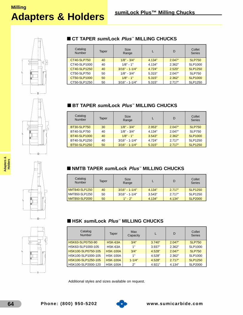
64 Phone: (800) 950-5202 www.sumicarb ide.com
Milling
Adapters & HoldersA
dapt
ers
&H
olde
rs
sumiLock Plus™ Milling Chucks
L
D
D
L
L
D
■ BT TAPER sumi Lock Plus ™ MILLING CHUCKS
■ NMTB TAPER sumi Lock Plus ™ MILLING CHUCKS
■ CT TAPER sumi Lock Plus ™ MILLING CHUCKS
Additional styles and sizes available on request.
8.40008.4000
L
D
■ HSK sumi Lock Plus ™ MILLING CHUCKS
HSK63-SLP0750-90HSK63-SLP1000-105HSK100-SLP0750-105HSK100-SLP1000-105HSK100-SLP1250-105HSK100-SLP2000-120
Taper Max L D ColletCapacity Series
HSK-63A 3/4" 3.740" 2.047" SLP750HSK-63A 1" 3.937" 2.362" SLP1000
HSK-100A 3/4" 4.528" 2.047" SLP750HSK-100A 1" 4.528" 2.362" SLP1000HSK-100A 1-1/4" 4.528" 2.717" SLP1250HSK-100A 2" 4.921" 4.134" SLP2000
Taper Size L D ColletRange Series
40 3/16" - 1-1/4" 4.134" 2.717" SLP125050 3/16" - 1-1/4" 3.543" 2.717" SLP125050 1" - 2" 4.134" 4.134" SLP2000
NMTB40-SLP1250NMTB50-SLP1250NMTB50-SLP2000
BT30-SLP750BT40-SLP750BT40-SLP1000BT40-SLP1250BT50-SLP1250
Taper Size L D ColletRange Series
30 1/8" - 3/4" 2.953" 2.047" SLP75040 1/8" - 3/4" 4.134" 2.047" SLP75040 1/8" - 1" 3.543" 2.362" SLP100040 3/16" - 1-1/4" 4.724" 2.717" SLP125050 3/16" - 1-1/4" 5.315" 2.717" SLP1250
CT40-SLP750CT40-SLP1000CT40-SLP1250CT50-SLP750CT50-SLP1000CT50-SLP1250
Taper Size L D ColletRange Series
40 1/8" - 3/4" 4.134" 2.047" SLP75040 1/8" - 1" 4.134" 2.362" SLP100040 3/16" - 1-1/4" 4.724" 2.520" SLP125050 1/8" - 3/4" 5.315" 2.047" SLP75050 1/8" - 1" 5.315" 2.362" SLP100050 3/16" - 1-1/4" 5.315" 2.717" SLP1250
CatalogNumber
CatalogNumber
CatalogNumber
CatalogNumber

65Phone: (800) 950-5202 www.sumicarb ide.com
sumiLock Plus™ Collets and AccessoriesMilling
Adapters & HoldersA
dapters &H
olders
■ SLP750 sumi Lock Plus ™ COLLETSMetric
SLP750-6
SLP750-7
SLP750-8
SLP750-10
SLP750-12
SLP750-14
SLP750-16
StandardCollet
6mm
7mm
8mm
10mm
12mm
14mm
16mm
ColletI.D.
SLP750-6C
SLP750-7C
SLP750-8C
SLP750-10C
SLP750-12C
SLP750-14C
SLP750-16C
SLP750N-6C
SLP750N-7C
SLP750N-8C
SLP750N-10C
SLP750N-12C
SLP750N-14C
SLP750N-16C
SLP750N-6S
SLP750N-7S
SLP750N-8S
SLP750N-10S
SLP750N-12S
SLP750N-14S
SLP750N-16S
SLP750N-6N
SLP750N-7N
SLP750N-8N
SLP750N-10N
SLP750N-12N
SLP750N-14N
SLP750N-16N
CoolantCollet
Coolant-ThruNut Slotted Nut Nozzle Nut
Inch
SLP750-008
SLP750-012
SLP750-016
SLP750-020
SLP750-024
SLP750-028
SLP750-032
SLP750-036
SLP750-040
1/8"
3/16"
1/4"
5/16"
3/8"
7/16"
1/2"
9/16"
5/8"
ColletI.D.
SLP750-008C
SLP750-012C
SLP750-016C
SLP750-020C
SLP750-024C
SLP750-028C
SLP750-032C
SLP750-036C
SLP750-040C
SLP750N-008C
SLP750N-012C
SLP750N-016C
SLP750N-020C
SLP750N-024C
SLP750N-028C
SLP750N-032C
SLP750N-036C
SLP750N-040C
SLP750N-008S
SLP750N-012S
SLP750N-016S
SLP750N-020S
SLP750N-024S
SLP750N-028S
SLP750N-032S
SLP750N-036S
SLP750N-040S
SLP750N-008N
SLP750N-012N
SLP750N-016N
SLP750N-020N
SLP750N-024N
SLP750N-028N
SLP750N-032N
SLP750N-036N
SLP750N-040N
CoolantCollet
Coolant-ThruNut Slotted Nut Nozzle Nut
sumi Lock Plus ™ ColletsThe sumiLock PlusTM Milling Chuck Collets aremanufactured to uniformly collapse around thecutting tool shank. This provides maximumgripping power, and concentric positioning of thecutting tool. Standard collets and coolant collets(not pictured) are available for all sizes of sumiLockPlusTM Milling Chucks. SumiLockTM Collets will fitsumiLock PlusTM Milling Collets, but cannotaccommodate the sumiLock PlusTM accessory nuts.
Coolant-Thru NutThe Coolant-Thru Nut forms acomplete seal around the cuttingtool. This is beneficial for coolant-thru cutting tools. The coolantcollet and Coolant-Thru Nut mustbe ordered on size for eachcutting tool.
Slotted NutThe Slotted Nut allows coolant totravel down the tool’s shank to itscutting edge. This is well suitedfor non-coolant-thru cutting tools.The coolant collet and Slotted Nutmust be ordered on size for eachcutting tool.
Nozzle NutThe Nozzle Nut allows you todirect coolant to the cutting edgevia three nozzles. This is ideal forcoolant-thru cutting tools,specially when the cutting toolshank is smaller than the cuttingdiameter. The coolant collet andNozzle Nut must be ordered onsize for each cutting tool.

66 Phone: (800) 950-5202 www.sumicarb ide.com
Milling
Adapters & HoldersA
dapt
ers
&H
olde
rs
sumiLock Plus™ Milling Chucks
■ SLP1250 sumi Lock Plus ™ COLLETS
Metric
SLP1250-6
SLP1250-8
SLP1250-10
SLP1250-12
SLP1250-14
SLP1250-16
SLP1250-20
SLP1250-25
StandardCollet
6mm
8mm
10mm
12mm
14mm
16mm
20mm
25mm
ColletI.D.
SLP1250-6C
SLP1250-8C
SLP1250-10C
SLP1250-12C
SLP1250-14C
SLP1250-16C
SLP1250-20C
SLP1250-25C
SLP1250N-6C
SLP1250N-8C
SLP1250N-10C
SLP1250N-12C
SLP1250N-14C
SLP1250N-16C
SLP1250N-20C
SLP1250N-25C
SLP1250N-6S
SLP1250N-8S
SLP1250N-10S
SLP1250N-12S
SLP1250N-14S
SLP1250N-16S
SLP1250N-20S
SLP1250N-25S
SLP1250N-6N
SLP1250N-8N
SLP1250N-10N
SLP1250N-12N
SLP1250N-14N
SLP1250N-16N
SLP1250N-20N
SLP1250N-25N
CoolantCollet
Coolant-ThruNut Slotted Nut Nozzle Nut
Inch
SLP1250-012
SLP1250-016
SLP1250-020
SLP1250-024
SLP1250-028
SLP1250-032
SLP1250-036
SLP1250-040
SLP1250-048
SLP1250-056
SLP1250-064
StandardCollet
3/16"
1/4"
5/16"
3/8"
7/16"
1/2"
9/16"
5/8"
3/4"
7/8"
1"
ColletI.D.
SLP1250-012C
SLP1250-016C
SLP1250-020C
SLP1250-024C
SLP1250-028C
SLP1250-032C
SLP1250-036C
SLP1250-040C
SLP1250-048C
SLP1250-056C
SLP1250-064C
SLP1250N-012C
SLP1250N-016C
SLP1250N-020C
SLP1250N-024C
SLP1250N-028C
SLP1250N-032C
SLP1250N-036C
SLP1250N-040C
SLP1250N-048C
SLP1250N-056C
SLP1250N-064C
SLP1250N-012S
SLP1250N-016S
SLP1250N-020S
SLP1250N-024S
SLP1250N-028S
SLP1250N-032S
SLP1250N-036S
SLP1250N-040S
SLP1250N-048S
SLP1250N-056S
SLP1250N-064S
SLP1250N-012N
SLP1250N-016N
SLP1250N-020N
SLP1250N-024N
SLP1250N-028N
SLP1250N-032N
SLP1250N-036N
SLP1250N-040N
SLP1250N-048N
SLP1250N-056N
SLP1250N-064N
CoolantCollet
Coolant-ThruNut Slotted Nut Nozzle Nut
■ SLP1000 sumi Lock Plus ™ COLLETS
Metric
SLP1000-6
SLP1000-8
SLP1000-10
SLP1000-12
SLP1000-14
SLP1000-16
SLP1000-18
SLP1000-20
StandardCollet
6mm
8mm
10mm
12mm
14mm
16mm
18mm
20mm
ColletI.D.
SLP1000-6C
SLP1000-8C
SLP1000-10C
SLP1000-12C
SLP1000-14C
SLP1000-16C
SLP1000-18C
SLP1000-20C
SLP1000N-6C
SLP1000N-8C
SLP1000N-10C
SLP1000N-12C
SLP1000N-14C
SLP1000N-16C
SLP1000N-18C
SLP1000N-20C
SLP1000N-6S
SLP1000N-8S
SLP1000N-10S
SLP1000N-12S
SLP1000N-14S
SLP1000N-16S
SLP1000N-18S
SLP1000N-20S
SLP1000N-6N
SLP1000N-8N
SLP1000N-10N
SLP1000N-12N
SLP1000N-14N
SLP1000N-16N
SLP1000N-18N
SLP1000N-20N
CoolantCollet
Coolant-ThruNut Slotted Nut Nozzle Nut
Inch
SLP1000-008
SLP1000-012
SLP1000-016
SLP1000-020
SLP1000-024
SLP1000-028
SLP1000-032
SLP1000-040
SLP1000-048
SLP1000-056
StandardCollet
1/8"
3/16"
1/4"
5/16"
3/8"
7/16"
1/2"
5/8"
3/4"
7/8"
ColletI.D.
SLP1000-008C
SLP1000-012C
SLP1000-016C
SLP1000-020C
SLP1000-024C
SLP1000-028C
SLP1000-032C
SLP1000-040C
SLP1000-048C
SLP1000-056C
SLP1000N-008C
SLP1000N-012C
SLP1000N-016C
SLP1000N-020C
SLP1000N-024C
SLP1000N-028C
SLP1000N-032C
SLP1000N-040C
SLP1000N-048C
SLP1000N-056C
SLP1000N-008S
SLP1000N-012S
SLP1000N-016S
SLP1000N-020S
SLP1000N-024S
SLP1000N-028S
SLP1000N-032S
SLP1000N-040S
SLP1000N-048S
SLP1000N-056S
SLP1000N-008N
SLP1000N-012N
SLP1000N-016N
SLP1000N-020N
SLP1000N-024N
SLP1000N-028N
SLP1000N-032N
SLP1000N-040N
SLP1000N-048N
SLP1000N-056N
CoolantCollet
Coolant-ThruNut Slotted Nut Nozzle Nut

67Phone: (800) 950-5202 www.sumicarb ide.com
sumiLock Plus™ Collets and AccessoriesMilling
Adapters & HoldersA
dapters &H
olders
SLP750MC–SPANSLP1000MC–SPANSLP1250MC–SPANSLP2000MC–SPAN
■ SLP SPANNER WRENCHES
For Use With
3/4" Capacity Chucks1" Capacity Chucks
1-1/4" Capacity Chucks2" Capacity Chucks
CatalogNumber
■ SLP2000 sumi Lock Plus ™ COLLETS
Inch
SLP2000-064SLP2000-080SLP2000-096
StandardCollet
ColletI.D.1"
1-1/4"1-1/2"
SLP2000-064CSLP2000-080CSLP2000-096C
SLP2000N-064CSLP2000N-080CSLP2000N-096C
SLP2000N-064SSLP2000N-080SSLP2000N-096S
SLP2000N-064NSLP2000N-080NSLP2000N-096N
CoolantCollet
Coolant-ThruNut Slotted Nut Nozzle Nut
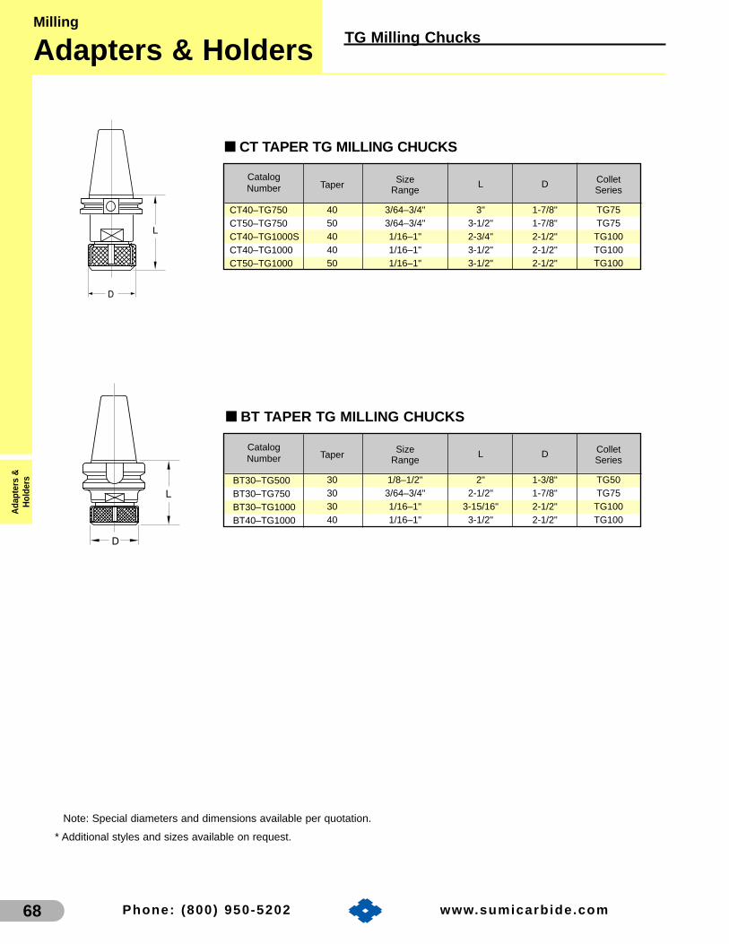
68 Phone: (800) 950-5202 www.sumicarb ide.com
Milling
Adapters & HoldersA
dapt
ers
&H
olde
rs
TG Milling Chucks
■ CT TAPER TG MILLING CHUCKS
■ BT TAPER TG MILLING CHUCKS
Note: Special diameters and dimensions available per quotation.
* Additional styles and sizes available on request.
Taper Size L D ColletRange Series
30 1/8–1/2" 2" 1-3/8" TG5030 3/64–3/4" 2-1/2" 1-7/8" TG7530 1/16–1" 3-15/16" 2-1/2" TG10040 1/16–1" 3-1/2" 2-1/2" TG100
BT30–TG500BT30–TG750BT30–TG1000BT40–TG1000
Taper Size L D ColletRange Series
40 3/64–3/4" 3" 1-7/8" TG7550 3/64–3/4" 3-1/2" 1-7/8" TG7540 1/16–1" 2-3/4" 2-1/2" TG10040 1/16–1" 3-1/2" 2-1/2" TG10050 1/16–1" 3-1/2" 2-1/2" TG100
CT40–TG750CT50–TG750CT40–TG1000SCT40–TG1000CT50–TG1000
CatalogNumber
CatalogNumber

69Phone: (800) 950-5202 www.sumicarb ide.com
TG Collets and AccessoriesMilling
Adapters & HoldersA
dapters &H
olders
TG75 COLLETSInch
Collet I.D.
3/64"1/16"5/64"3/32"7/64"1/8"
9/64"5/32"11/64"3/16"
13/64"7/32"
15/64"1/4"
17/64"9/32"
19/64"5/16"
21/64"11/32"23/64"
3/8"25/64"
TG075–003TG075–004TG075–005TG075–006TG075–007TG075–008TG075–009TG075–010TG075–011TG075–012TG075–013TG075–014TG075–015TG075–016TG075–017TG075–018TG075–019TG075–020TG075–021TG075–022TG075–023TG075–024TG075–025
Collet I.D.
13/32"27/64"7/16"
29/64"15/32"31/64"
1/2"33/64"17/32"35/64"9/16"
37/64"19/32"39/64"
5/8"41/64"21/32"43/64"11/16"45/64"23/32"47/64"
3/4"
TG075–026TG075–027TG075–028 TG075–029TG075–030TG075–031TG075–032TG075–033TG075–034TG075–035TG075–036TG075–037TG075–038TG075–039TG075–040TG075–041 TG075–042TG075–043TG075–044TG075–045TG075–046TG075–047TG075–048
TG50 COLLETSInch
Collet I.D.
1/8"9/64"5/32"11/64"3/16"
13/64"7/32"
15/64"1/4"
17/64"9/32"
19/64"5/16"
TG050–008TG050–009TG050–010TG050–011TG050–012TG050–013TG050–014TG050–015TG050–016TG050–017TG050–018TG050–019TG050–020
Collet I.D.
21/64"11/32"23/64"
3/8"25/64"13/32"27/64"7/16"
29/64"15/32"31/64"
1/2"
TG050–021TG050–022TG050–023TG050–024TG050–025TG050–026TG050–027TG050–028TG050–029TG050–030TG050–031TG050–032
(Continued on next page)Note: TG Collets collapse approximately 1/64"
MetricCatalog Number
TG100-204
TG100-206
TG100-208
TG100-210
TG100-212
TG100-214
TG100-216
–
TG100-206C
TG100-208C
TG100-210C
TG100-212C
TG100-214C
TG100-216C
4mm
6mm
8mm
10mm
12mm
14mm
16mm
StandardCollet
CoolantCollet
ColletI.D.
Catalog Number
TG100-218
TG100-220
TG100-222
TG100-224
TG100-225
TG100-226
TG100-218C
TG100-220C
TG100-222C
TG100-224C
TG100-225C
TG100-226C
18mm
20mm
22mm
24mm
25mm
26mm
StandardCollet
CoolantCollet
ColletI.D.
TG100 COLLETS
TG100 COLLETSInch
TG100–004
TG100–005
TG100–006
TG100–007
TG100–008
TG100–009
TG100–010
TG100–011
TG100–012
TG100–013
TG100–014
TG100–015
TG100–016
TG100–017
TG100–018
TG100–019
TG100–020
TG100–021
TG100–022
TG100–023
TG100–024
TG100–025
TG100–026
TG100–027
TG100–028
TG100–029
TG100–030
TG100–031
TG100–032
TG100–033
TG100–034
–
–
–
–
–
–
–
–
–
–
–
–
TG100–016C
TG100–017C
TG100–018C
TG100–019C
TG100–020C
TG100–021C
TG100–022C
TG100–023C
TG100–024C
TG100–025C
TG100–026C
TG100–027C
TG100–028C
TG100–029C
TG100–030C
TG100–031C
TG100–032C
TG100–033C
TG100–034C
1/16"
5/64"
3/32"
7/64"
1/8"
9/64"
5/32"
11/64"
3/16"
13/64"
7/32"
15/64"
1/4"
17/64"
9/32"
19/64"
5/16"
21/64"
11/32"
23/64"
3/8"
25/64"
13/32"
27/64"
7/16"
29/64"
15/32"
31/64"
1/2"
33/64"
17/32"
Catalog NumberStandard
ColletCoolantCollet
ColletI.D.
TG100–035
TG100–036
TG100–037
TG100–038
TG100–039
TG100–040
TG100–041
TG100–042
TG100–043
TG100–044
TG100–045
TG100–046
TG100–047
TG100–048
TG100–049
TG100–050
TG100–051
TG100–052
TG100–053
TG100–054
TG100–055
TG100–056
TG100–057
TG100–058
TG100–059
TG100–060
TG100–061
TG100–062
TG100–063
TG100–064
TG100–035C
TG100–036C
TG100–037C
TG100–038C
TG100–039C
TG100–040C
TG100–041C
TG100–042C
TG100–043C
TG100–044C
TG100–045C
TG100–046C
TG100–047C
TG100–048C
TG100–049C
TG100–050C
TG100–051C
TG100–052C
TG100–053C
TG100–054C
TG100–055C
TG100–056C
TG100–057C
TG100–058C
TG100–059C
TG100–060C
TG100–061C
TG100–062C
TG100–063C
TG100–064C
35/64"
9/16"
37/64"
19/32"
39/64"
5/8"
41/64"
21/32"
43/64"
11/16"
45/64"
23/32"
47/64"
3/4"
49/64"
25/32"
51/64"
13/16"
53/64"
27/32"
55/64"
7/8"
57/64"
29/32"
59/64"
15/16"
61/64"
31/32"
63/64"
1"
Catalog NumberStandard
ColletCoolantCollet
ColletI.D.
CatalogNumber
CatalogNumber
CatalogNumber
CatalogNumber
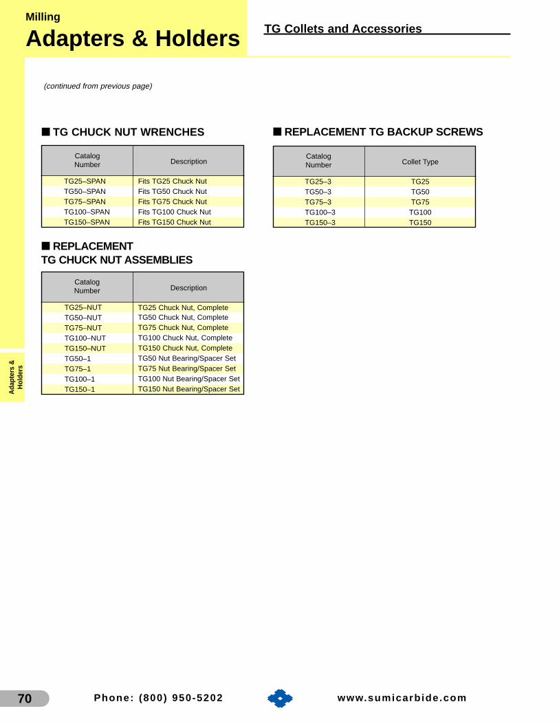
70 Phone: (800) 950-5202 www.sumicarb ide.com
Milling
Adapters & HoldersA
dapt
ers
&H
olde
rs
TG Collets and Accessories
■ REPLACEMENT TG BACKUP SCREWS■ TG CHUCK NUT WRENCHES
■ REPLACEMENTTG CHUCK NUT ASSEMBLIES
(continued from previous page)
Collet Type
TG25TG50TG75
TG100TG150
TG25–3TG50–3TG75–3TG100–3TG150–3
Description
Fits TG25 Chuck NutFits TG50 Chuck NutFits TG75 Chuck NutFits TG100 Chuck NutFits TG150 Chuck Nut
TG25–SPANTG50–SPANTG75–SPANTG100–SPANTG150–SPAN
Description
TG25 Chuck Nut, CompleteTG50 Chuck Nut, CompleteTG75 Chuck Nut, CompleteTG100 Chuck Nut, CompleteTG150 Chuck Nut, CompleteTG50 Nut Bearing/Spacer SetTG75 Nut Bearing/Spacer SetTG100 Nut Bearing/Spacer SetTG150 Nut Bearing/Spacer Set
TG25–NUTTG50–NUTTG75–NUTTG100–NUTTG150–NUTTG50–1TG75–1TG100–1TG150–1
CatalogNumber
CatalogNumber
CatalogNumber

71Phone: (800) 950-5202 www.sumicarb ide.com
ER Milling ChucksMilling
Adapters & HoldersA
dapters &H
olders
■ NMTB TAPER ER MILLING CHUCKS
■ CT TAPER ER MILLING CHUCKS
■ BT TAPER ER MILLING CHUCKS
Taper Size L D ColletRange Series
40 1/32–13/32" 1-3/4" 1-1/4" ER16NMTB40-ER16
Taper Size L D ColletRange Series
40 .019–.275" 2-1/2" 3/4" ER1140 1/32–13/32" 3-1/2" 1-1/4" ER1650 1/32–13/32" 4-1/8" 1-1/4" ER1640 .039–.511" 2-1/2" 1-3/8" ER2050 .039–.511" 2-1/2" 1-3/8" ER2040 .039–.629" 2-1/2" 1-11/16" ER2550 .039–.629" 2-1/2" 1-11/16" ER2540 .078–.787" 3-1/8" 2" ER3250 .078–.787" 4" 2" ER3240 .118–1.023" 3" 2-1/2" ER4050 .118–1.023" 4" 2-1/2" ER40
CT40-ER11CT40-ER16CT50-ER16CT40-ER20CT50-ER20CT40-ER25CT50-ER25CT40-ER32CT50-ER32CT40-ER40CT50-ER40
* Additional styles and sizes available on request.
ER Collets are on the following page.
BT30-ER11BT30-ER11LBT40-ER11BT30-ER16BT30-ER16LBT40-ER16BT50-ER16BT40-ER20BT50-ER20BT30-ER25BT30-ER25LBT40-ER25BT50-ER25BT30-ER32BT40-ER32BT50-ER32BT50-ER40
Taper Size L D ColletRange Series
30 .019–.275" 2" 3/4" ER1130 .019–.275" 4" 3/4" ER1140 .019–.275" 2-1/2" 3/4" ER4030 1/32–13/32" 2-3/8" 1-1/4" ER1630 1/32–13/32" 4" 1-1/4" ER1640 1/32–13/32" 3-1/2" 1-1/4" ER1650 1/32–13/32" 4-1/8" 1-1/4" ER1640 .039–.511" 2-1/4" 1-3/8" ER2050 .039–.511" 2-5/8" 1-3/8" ER2030 .039–.629" 2" 1-5/8" ER2530 .039–.629" 4" 1-5/8" ER2540 .039–.629" 2-1/4" 1-5/8" ER2550 .039–.629" 2-5/8" 1-5/8" ER2530 .078–.787" 3" 2" ER3240 .078–.787" 3-1/8" 2" ER3250 .078–.787" 4" 2" ER3250 .118–1.023" 4" 2-1/2" ER40
CatalogNumber
CatalogNumber
CatalogNumber

72 Phone: (800) 950-5202 www.sumicarb ide.com
Milling
Adapters & HoldersA
dapt
ers
&H
olde
rs
ER Collets and Accessories
Note: ER Series 11 Collets collapseapproximately 1/64."
Note: ER Series 16 through 40 colletscollapse approximately 1/32".
CatalogNumber Inch
ER11-012C 3/16”ER11-013C 13/64”ER11-014C 7/32”ER11-015C 15/64”ER11-016C 1/4”ER11-017C 17/64”
CatalogNumber Metric Inch
ER11-039 0.5-1mm .019-.039”ER11-059 1-1.5mm .039-.059”ER11-078 1.5-2mm .059-.078”ER11-098 2-2.5mm .078-.098”ER11-118 2.5-3mm .098-.118”ER11-137 3-3.5mm .118-.137”ER11-157 3.5-4mm .137-.157”ER11-177 4-4.5mm .157-.177”ER11-196 4.5-5mm .177-.196”ER11-216 5-5.5mm .196-.216”ER11-236 5.5-6mm .216-.236”ER11-255 6-6.5mm .236-.255”ER11-275 6.5-7mm .255-.275”
ER SERIES 11 STANDARD COLLETS
Metric
Collet I.D. CatalogNumber Metric
ER11-157C 4.0mmER11-177C 4.5mmER11-196C 5.0mmER11-216C 5.5mmER11-236C 6.0mmER11-255C 6.5mm
ER SERIES 11 COOLANT COLLETS
Metric
Collet I.D.
ER SERIES 11 COOLANT COLLETS
Inch
Collet I.D.
CatalogNumber Metric Inch
ER20-078 1-2mm .039-.078”ER20-118 2-3mm .078-.118”ER20-137 2.5-3.5mm .098-.137”ER20-157 3-4mm .118-.157”ER20-196 4-5mm .157-.196”ER20-236 5-6mm .196-.236”ER20-275 6-7mm .236-.275”ER20-314 7-8mm .275-.314”ER20-354 8-9mm .314-.354”ER20-393 9-10mm .354-.393”ER20-433 10-11mm .393-.433”ER20-452 11-11.5mm .433-.452”ER20-472 11-12mm .452-.472”ER20-511 12-13mm .472-.511”
ER SERIES 20STANDARD COLLETS
Metric
Collet I.D. CatalogNumber Inch
ER20-012C 3/16”
ER SERIES 20 COOLANT COLLETS
Inch
Collet I.D.CatalogNumber Metric
ER20-196C 5.0mmER20-216C 5.5mmER20-236C 6.0mmER20-255C 6.5mmER20-275C 7.0mmER20-295C 7.5mmER20-314C 8.0mmER20-334C 8.5mmER20-354C 9.0mmER20-374C 9.5mmER20-393C 10.0mmER20-413C 10.5mmER20-433C 11.0mmER20-452C 11.5mmER20-472C 12.0mmER20-492C 12.5mmER20-511C 13.0mm
ER SERIES 20 COOLANT COLLETS
Metric
Collet I.D.
CatalogNumber Inch
ER16-002 1/64-1/32”ER16-004 1/32-1/16”ER16-006 1/16-3/32”ER16-008 3/32-1/8”ER16-010 1/8-5/32”ER16-012 5/32-3/16”ER16-014 3/16-7/32”ER16-016 7/32-1/4”ER16-018 1/4-9/32”ER16-020 9/32-5/16”ER16-022 5/16-11-32”ER16-024 11/32-3/8”ER16-026 3/8-13/32”
CatalogNumber Metric Inch
ER16-039 0.5-1mm .019-.039”ER16-059 1-1.5mm .039-.059”ER16-078 1.5-2mm .059-.078”ER16-098 2-2.5mm .078-.098”ER16-118 2.5-3mm .098-.118”ER16-137 3-3.5mm .118-.137”ER16-157 3.5-4mm .137-.157”ER16-177 4-4.5mm .157-.177”ER16-196 4.5-5mm .177-.196”ER16-216 5-5.5mm .196-.216”ER16-236 5.5-6mm .216-.236”ER16-255 6-6.5mm .236-.255”ER16-275 6.5-7mm .255-.275”ER16-295 7-7.5mm .275-.295”ER16-314 7.5-8mm .295-.314”ER16-334 8-8.5mm .314-.334”ER16-354 8.5-9mm .334-.354”ER16-374 9-9.5mm .354-.374”ER16-393 9.5-10mm .374-.393”
ER SERIES 16 STANDARD COLLETS
Metric
Collet I.D.
CatalogNumber Metric
ER16-157C 4.0mmER16-177C 4.5mmER16-196C 5.0mmER16-216C 5.5mmER16-236C 6.0mmER16-255C 6.5mmER16-275C 7.0mmER16-295C 7.5mmER16-314C 8.0mmER16-334C 8.5mmER16-354C 9.0mmER16-374C 9.5mmER16-393C 10.0mm
ER SERIES 16 COOLANT COLLETS
Metric
Collet I.D.
ER SERIES 16 STANDARD COLLETS
Inch
Collet I.D.
ER SERIES 16 COOLANTCOLLETS
Inch
CatalogNumber Inch
ER16-012C 3/16”ER16-013C 13/64”ER16-014C 7/32”ER16-015C 15/64”ER16-016C 1/4”ER16-017C 17/64”ER16-018C 9/32”ER16-019C 19/64”ER16-020C 5/16”ER16-021C 21/64”ER16-022C 11/32”ER16-023C 23/64”ER16-024C 3/8”ER16-025C 25/64”ER16-026C 13/32”
Collet I.D.

73Phone: (800) 950-5202 www.sumicarb ide.com
Note: ER Series 11 collets collapse approximately 1/64˝.
CatalogNumber Metric Inch
ER25-078 1-2mm .039-.078”ER25-118 2-3mm .078-.118”ER25-137 2.5-3.5mm .098-.137”ER25-157 3-4mm .118-.157”ER25-196 4-5mm .157-.196”ER25-236 5-6mm .196-.236”ER25-275 6-7mm .236-.275”ER25-314 7-8mm .275-.314”ER25-354 8-9mm .314-.354”ER25-393 9-10mm .354-.393”ER25-433 10-11mm .393-.433”ER25-452 11-11.5mm .433-.452”ER25-472 11-12mm .452-.472”ER25-511 12-13mm .472-.511”ER25-551 13-14mm .511-.551”ER25-590 14-15mm .551-.590”ER25-629 15-16mm .590-.629”
ER SERIES 25 STANDARD COLLETS
Metric
Collet I.D. CatalogNumber Metric
ER25-236C 6.0mmER25-255C 6.5mmER25-275C 7.0mmER25-295C 7.5mmER25-314C 8.0mmER25-334C 8.5mmER25-354C 9.0mmER25-374C 9.5mmER25-393C 10.0mmER25-413C 10.5mmER25-433C 11.0mmER25-452C 11.5mmER25-472C 12.0mmER25-492C 12.5mmER25-511C 13.0mmER25-531C 13.5mmER25-551C 14.0mmER25-570C 14.5mmER25-590C 15.0mmER25-610C 15.5mmER25-629C 16.0mm
ER SERIES 25 COOLANT COLLETS
Metric
Collet I.D. CatalogNumber Inch
ER25-016C 1/4”ER25-017C 17/64”ER25-018C 9/32”ER25-019C 19/64”ER25-020C 5/16”ER25-021C 21/64”ER25-022C 11/32”ER25-023C 23/64”ER25-024C 3/8”
ER SERIES 25 COOLANT COLLETS
InchCollet I.D.
CatalogNumber Metric Inch
ER32-118 2-3mm .078-.118”ER32-137 2.5-3.5mm .098-.137”ER32-157 3-4mm .118-.157”ER32-196 4-5mm .157-.196”ER32-236 5-6mm .196-.236”ER32-275 6-7mm .236-.275”ER32-314 7-8mm .275-.314”ER32-354 8-9mm .314-.354”ER32-393 9-10mm .354-.393”ER32-433 10-11mm .393-.433”ER32-452 11-11.5mm .433-.452”ER32-472 11-12mm .452-.472”ER32-511 12-13mm .472-.511”ER32-551 13-14mm .511-.551”ER32-590 14-15mm .551-.590”ER32-629 15-16mm .590-.629”ER32-669 16-17mm .629-.669”ER32-708 17-18mm .669-.708”ER32-748 18-19mm .708-.748”ER32-767 18.5-19.5mm .728-.767”ER32-787 19-20mm .748-.787”
ER SERIES 32 STANDARD COLLETS
Metric
Collet I.D. CatalogNumber Metric
ER32-393C 10.0mmER32-413C 10.5mmER32-433C 11.0mmER32-452C 11.5mmER32-472C 12.0mmER32-492C 12.5mmER32-511C 13.0mmER32-531C 13.5mmER32-551C 14.0mmER32-570C 14.5mmER32-590C 15.0mmER32-610C 15.5mmER32-629C 16.0mmER32-649C 16.5mmER32-669C 17.0mmER32-688C 17.5mmER32-708C 18.0mmER32-728C 18.5mmER32-748C 19.0mmER32-767C 19.5mmER32-787C 20.0mm
ER SERIES 32 COOLANT COLLETS
Metric
Collet I.D.
ER Collets and AccessoriesMilling
Adapters & HoldersA
dapters &H
olders

74 Phone: (800) 950-5202 www.sumicarb ide.com
ER011–HEXER016–SPANER020–SPANER025–SPANER032–SPANER040–SPAN
REPLACEMENT ER BACKUP SCREWS
Collet Type
ER11ER16ER20ER25ER32ER40
ER11–3–ScrewER16–3–ScrewER20–3–ScrewER25–3–ScrewER32–3–ScrewER40–3–Screw
ER CHUCK NUT WRENCHES
Description
Fits ER11 Chuck NutFits ER16 Chuck NutFits ER20 Chuck NutFits ER25 Chuck NutFits ER32 Chuck NutFits ER40 Chuck Nut
REPLACEMENT ER CHUCK NUTS
Description
ER11-NUT ER11 Chuck Nut, CompleteER16-NUT ER16 Chuck Nut, CompleteER20-NUT ER20 Chuck Nut, CompleteER25-NUT ER25 Chuck Nut, CompleteER32-NUT ER32 Chuck Nut, CompleteER40-NUT ER40 Chuck Nut, Complete
ER COLLET RACKS
ER NUT BEARINGS
Description
ER16 Bearing/Spacer SetER20 Bearing/Spacer SetER25 Bearing/Spacer SetER32 Bearing/Spacer SetER40 Bearing/Spacer Set
ER16–1ER20–1ER25–1ER32–1ER40–1
ER11–RACKER16–RACKER20–RACKER25–RACKER32–RACKER40–RACK
Description
ER11 Collet RackER16 Collet RackER20 Collet RackER25 Collet RackER32 Collet RackER40 Collet Rack
CatalogNumber Metric
ER40-393C 10.0mmER40-413C 10.5mmER40-433C 11.0mmER40-452C 11.5mmER40-472C 12.0mmER40-492C 12.5mmER40-511C 13.0mmER40-531C 13.5mmER40-551C 14.0mmER40-570C 14.5mmER40-590C 15.0mmER40-610C 15.5mmER40-629C 16.0mmER40-649C 16.5mmER40-669C 17.0mmER40-688C 17.5mmER40-708C 18.0mm
ER SERIES 40 COOLANT COLLETS
Metric
Collet I.D. CatalogNumber Metric
ER40-728C 18.5mmER40-748C 19.0mmER40-767C 19.5mmER40-787C 20.0mmER40-807C 20.5mmER40-826C 21.0mmER40-846C 21.5mmER40-866C 22.0mmER40-885C 22.5mmER40-905C 23.0mmER40-925C 23.5mmER40-944C 24.0mmER40-964C 24.5mmER40-984C 25.0mmER40-1003C 26.0mmER40-1023C 26.5mm
Collet I.D.CatalogNumber Metric Inch
ER40-157 3-4mm .118-.157”ER40-196 4-5mm .157-.196”ER40-236 5-6mm .196-.236”ER40-275 6-7mm .236-.275”ER40-314 7-8mm .275-.314”ER40-354 8-9mm .314-.354”ER40-393 9-10mm .354-.393”ER40-433 10-11mm .393-.433”ER40-452 11-11.5mm .433-.452”ER40-472 11-12mm .452-.472”ER40-511 12-13mm .472-.511”ER40-551 13-14mm .511-.551”ER40-590 14-15mm .551-.590”ER40-629 15-16mm .590-.629”ER40-669 16-17mm .629-.669”ER40-708 17-18mm .669-.708”ER40-748 18-19mm .708-.748”ER40-767 18.5-19.5mm .728-.767”ER40-787 19-20mm .748-.787”ER40-826 20-21mm .787-.826”ER40-866 21-22mm .826-.866”ER40-905 22-23mm .866-.905”ER40-944 23-24mm .905-.944”ER40-984 24-25mm .944-.984”ER40-1023 25-26mm .984-1.023”
ER SERIES 40 STANDARD COLLETS
Metric
Collet I.D.
CatalogNumber
CatalogNumber
CatalogNumber
CatalogNumber
CatalogNumber
Milling
Adapters & HoldersA
dapt
ers
&H
olde
rs
ER Collets and Accessories

75Phone: (800) 950-5202 www.sumicarb ide.com
■ CT40 ENDMILL HOLDERS
CT40-06-125EMHCT40-06-187EMHCT40-06-250EMHCT40-06-312EMHCT40-06-375EMHCT40-06-500EMHCT40-06-625EMHCT40-06-750EMHCT40-06-875EMHCT40-06-1000EMHCT40-06-1250EMHCT40-06-1500EMH
Taper d L D Set Screw RetentionSize Knob Thread
40 1/8" 2-3/8" 3/4" 6-32x1/4 5/8"-1140 3/16" 2-1/2" 3//4" 8-32x1/4 5/8"-1140 1/4" 2-1/2" 13/16" 1/4-28x1/4 5/8"-1140 5/16" 2-1/2" 7/8" 5/16-24x1/4 5/8"-1140 3/8" 2-1/2" 1" 3/8-24x5/16 5/8"-1140 1/2" 2-1/2" 1-3/8" 7/16-20x3/8 5/8"-1140 5/8" 3" 1-5/8" 9/16-18x1/2 5/8"-1140 3/4" 3" 1-3/4" 5/8-18x1/2 5/8"-1140 7/8" 3-1/2" 2" 5/8-18x1/2** 5/8"-1140 1" 4" 2-3/8" 3/4-16x11/16** 5/8"-1140 1-1/4" 4" 2-1/2" 3/4-16x11/16** 5/8"-1140 1-1/2" 4-1/2" 3" 3/4-16x11/16** 5/8"-11
Inch
■ CT50 ENDMILL HOLDERS
CT50-06-500EMHCT50-06-625EMHCT50-06-750EMHCT50-06-875EMHCT50-06-1000EMHCT50-06-1250EMHCT50-06-1500EMHCT50-06-2000EMH
Taper d L D Set Screw RetentionSize Knob Thread
50 1/2" 2-5/8" 1-3/8" 7/16-20x3/8 1"-8` 50 5/8" 3" 1-5/8" 9/16-18x1/2 1"-8
50 3/4" 3" 1-7/8" 5/8-18x1/2 1"-850 7/8" 3-3/4" 2" 5/8-18x1/2** 1"-850 1" 4" 2-3/8" 3/4-16x11/16** 1"-850 1-1/4" 4" 2-1/2" 3/4-16x11/16** 1"-850 1-1/2" 4-1/2" 3" 3/4-16x11/16** 1"-850 2" 5-3/8" 3-3/4" 1-14x7/8** 1"-8
Inch
CT40-06-6EMHCT40-06-8EMHCT40-06-10EMHCT40-06-12EMHCT40-06-18EMHCT40-06-20EMHCT40-06-25EMHCT40-06-32EMH
Taper d L D Set Screw RetentionSize Knob Thread
40 6mm 2-1/2" 13/16" 1/4-28x1/4 5/8"-1140 8mm 2-1/2" 7/8" 5/16-24x1/4 5/8"-1140 10mm 2-1/2" 1" 3/8-24x5/16 5/8"-1140 12mm 2-1/2" 1-3/8" 7/16-20x3/8 5/8"-1140 18mm 3" 1-3/4" 5/8-18x1/2 5/8"-1140 20mm 3" 1-3/4" 5/8-18x1/2 5/8"-1140 25mm 4" 2-3/8" 3/4-16x11/16** 5/8"-1140 32mm 4" 2-1/2" 3/4-16x11/16** 5/8"-11
Metric
CT50-06-16EMHCT50-06-18EMHCT50-06-20EMHCT50-06-25EMHCT50-06-32EMH
Taper d L D Set Screw RetentionSize Knob Thread
50 16mm 3" 1-5/8" 9/16-18x1/2 1"-850 18mm 3" 1-7/8" 5/8-18x1/2 1"-850 20mm 3" 1-7/8" 5/8-18x1/2 1"-850 25mm 4" 2-3/8" 3/4-16x11/16** 1"-850 32mm 4" 2-1/2" 3/4-16x11/16** 1"-8
Metric
* Additional styles and sizes available on request.**(2) Required for these holders
CatalogNumber
CatalogNumber
CatalogNumber
CatalogNumber
Endmill HoldersMilling
Adapters & HoldersA
dapters &H
olders

Milling
Adapters & HoldersA
dapt
ers
&H
olde
rs
Endmill Holders
76 Phone: (800) 950-5202 www.sumicarb ide.com
■ BT40 ENDMILL HOLDERS
Taper d L D Set Screw RetentionSize Knob Thread
40 1/8" 2-3/8" 3/4" 6-32x1/4 M16P240 3/16" 2-1/2" 3/4" 6-32x1/4 M16P240 1/4" 2-1/2" 13/16" 1/4-28x1/4 M16P240 5/16" 2-1/2" 7/8" 5/16-24x1/4 M16P240 3/8" 2-1/2" 1" 3/8-24x5/16 M16P240 1/2" 2-1/2" 1-3/8" 7/16-20x3/8 M16P240 5/8" 2-1/2" 1-11/16" 9/16-20x1/2 M16P240 3/4" 2-1/2" 1-7/8" 5/8-18x1/2 M16P240 7/8" 3-3/8" 2" 5/8-18x1/2** M16P240 1" 3-9/16" 2-3/8" 3/4-16x11/16** M16P240 1-1/4" 3-9/16" 2-1/2" 3/4-16x11/16** M16P240 1-1/2" 4-1/2" 3" 3/4-16x11/16** M16P2
Inch
**(2) Required for these holders
CT50-06-375AEMHCT50-06-500AEMHCT50-06-625AEMHCT50-06-750AEMHCT50-06-875AEMH
CT50-06-1000AEMHCT50-06-1250AEMHCT50-06-1500AEMHCT50-06-2000AEMH
Taper d L D Set Screw RetentionSize Knob Thread
50 3/8" 2-13/16" 1-3/8" 3/8-24UNF 1"-850 1/2" 2-3/4" 1-5/8" 3/8-24UNF 1"-850 5/8" 2-11/16" 1-13/16" 1/2-20UNF 1"-850 3/4" 2-5/8" 2" 1/2-20UNF 1"-850 7/8" 2-5/8" 2-1/4" 1/2-20UNF 1"-850 1" 3" 2-5/8" 3/4-16UNF 1"-850 1-1/4" 3" 2-7/8" 3/4-16UNF 1"-850 1-1/2" 4" 3-1/4" 3/4-16UNF 1"-850 2" 5-3/8" 4" 3/4-16UNF** 1"-8
Inch
■ CT50 AEROSPACE ENDMILL HOLDERS
■ BT50 ENDMILL HOLDERS
BT50-06-500EMHBT50-06-625EMHBT50-06-750EMHBT50-06-875EMH
BT50-06-1000EMHBT50-06-1250EMHBT50-06-1500EMHBT50-06-2000EMH
Taper d L D Set Screw RetentionSize Knob Thread
50 1/2" 3" 1-3/8" 7/16-20x3/8 M24P350 5/8" 3" 1-11/16" 5/8-18x1/2 M24P350 3/4" 3" 1-7/8" 5/8-18x1/2 M24P350 7/8" 4" 2" 5/8-18x1/2 M24P350 1" 4" 2-3/8" 3/4-16x11/16** M24P350 1-1/4" 4" 2-1/2" 3/4-16x11/16** M24P350 1-1/2" 4-1/2" 3" 3/4-16x11/16** M24P350 2" 5" 3-3/4" 1-14x7/8** M24P3
Inch
BT40-06-125EMHBT40-06-187EMHBT40-06-250EMHBT40-06-312EMHBT40-06-375EMHBT40-06-500EMHBT40-06-625EMHBT40-06-750EMHBT40-06-875EMH
BT40-06-1000EMHBT40-06-1250EMHBT40-06-1500EMH
CatalogNumber
CatalogNumber
CatalogNumber

Endmill HoldersMilling
Adapters & HoldersA
dapters &H
olders
77Phone: (800) 950-5202 www.sumicarb ide.com
L
D
■ K & T Series 200 ENDMILL HOLDERS
KT20-06-375EMHKT20-06-500EMHKT20-06-625EMHKT20-06-750EMHKT20-06-875EMHKT20-06-1000EMHKT20-06-1250EMH
Set ScrewD L Size
3/8" 1-15/16” 3/8-24x5/161/2" 1-15/16” 7/16-20X3/85/8" 1-15/16” 1/2-20X5/83/4" 1-15/16” 5/8-18X1/27/8" 1-15/16” 5/8-18X1/21" 1-15/16” 5/8-18X1/2
1-1/4" 1-15/16” 5/8-18X1/2
Inch
■ HSK ENDMILL HOLDERS
HSK63-250-80EMHHSK63-375-90EMHHSK63-500-95EMHHSK63-625-100EMHHSK63-750-100EMHHSK100-375-90EMHHSK100-500-100EMHHSK100-625-105EMHHSK100-750-110EMHHSK100-1000-115EMHHSK100-1250-120EMH
Taper d L D Set ScrewSize
HSK-63 1/4" 3-1/8" 1-1/8" M8PHSK-63 3/8" 3-7/16" 1-3/8" M10PHSK-63 1/2" 3-3/4" 1-5/8" M12PHSK-63 5/8" 3-15/16" 1-7/8" M14PHSK-63 3/4" 3-15/16" 2-1/16" M16P
HSK-100 3/8" 3-7/16" 1-3/8" M10PHSK-100 1/2" 3-5/16" 1-5/8" M12PHSK-100 5/8" 4-1/8" 1-7/8" M14PHSK-100 3/4" 4-5/16" 2-1/16" M16PHSK-100 1" 4-1/2" 2-9/16" M18PHSK-100 1-7/16" 4-3/4" 2-13/16" M20P
Inch
■ R8 ENDMILL HOLDERS
R8-32-3R8-40-3R8-48-3R8-56-3R8-64-3R8-80-3R8-96-3
Set ScrewD L C Size
1/2" 1-15/16" 1-3/8" 7/16-20x3/85/8" 1-1/2" 1-5/8" 9/16-18x1/23/4" 2-3/8" 1-7/8" 5/8-18x1/27/8" 2-3/4" 2" 5/8-18x1/2**1" 3-1/4" 2-3/8" 3/4-16x11/16**
1-1/4" 3-1/4" 2-1/2" 3/4-16x11/16**1-1/2" 3-3/4" 3" 3/4-16x11/16**
Inch
Note: Balanceable HSK holders are available upon request.
**(2) Required for these holders
CatalogNumber
CatalogNumber
CatalogNumber

Milling
Adapters & HoldersA
dapt
ers
&H
olde
rs
Endmill Holders
78 Phone: (800) 950-5202 www.sumicarb ide.com
■ NMTB 30 ENDMILL HOLDERS
NMTB30-125EMHNMTB30-187EMHNMTB30-250EMHNMTB30-312EMHNMTB30-375EMHNMTB30-500EMHNMTB30-625EMHNMTB30-750EMHNMTB30-875EMHNMTB30-1000EMHNMTB30-1250EMH
Taper d L D Set ScrewSize
30 1/8" 1-3/4" 3/4" 6-32x1/430 3/16" 1-3/4" 3/4" 8-32x1/430 1/4" 1-3/4" 13/16" 1/4-28x1/430 5/16" 1-3/4" 7/8" 5/16-24x1/430 3/8" 1-3/4" 1" 3/8-24x5/1630 1/2" 1-3/4" 1-3/8" 7/16-20x3/830 5/8" 1-3/4" 1-7/16" 9/16-18x1/230 3/4" 2-1/4" 1-7/8" 5/8-18x1/230 7/8" 2-1/2" 2" 5/8-18x1/2**30 1" 2-11/16" 2-3/8" 3/4-16x11/16**30 1-1/4" 3-5/8" 2-1/2" 3/4-16x11/16**
Inch
■ NMTB 40 ENDMILL HOLDERS
NMTB40-125EMHNMTB40-187EMHNMTB40-250EMHNMTB40-312EMHNMTB40-375EMHNMTB40-500EMHNMTB40-625EMHNMTB40-750EMHNMTB40-875EMHNMTB40-1000EMHNMTB40-1250EMHNMTB40-1500EMH
Taper d L D Set ScrewSize
40 1/8" 2-5/16" 3/4" 6-32x1/440 3/16" 2-5/16" 3/4" 8-32x1/440 1/4" 2-5/16" 13/16" 1/4-28x1/440 5/16" 2-5/16" 7/8" 5/16-24x1/440 3/8" 2-5/16" 1" 3/8-24x5/1640 1/2" 2-5/16" 1-3/8" 7/16-20x3/840 5/8" 2-5/16" 1-11/16" 9/16-18x1/240 3/4" 2-5/16" 1-7/8" 5/8-18x1/240 7/8" 2-15/16" 2" 5/8-18x1/2**40 1" 3-3/8" 2-3/8" 3/4-16x11/16**40 1-1/4" 3-11/16" 2-1/2" 3/4-16x11/16**40 1-1/2" 3-15/16" 3" 3/4-16x11/16**
Inch
**(2) Required for these holders.
CatalogNumber
CatalogNumber

Endmill Holder Extensions and PartsMilling
Adapters & HoldersA
dapters &H
olders
79Phone: (800) 950-5202 www.sumicarb ide.com
6"
■ ENDMILL HOLDER EXTENSIONS - STRAIGHT SHANK
S75-125EMHES75-187EMHES75-250EMHES75-312EMHES10-375EMHES10-500EMHE
End Mill Shank Set ScrewSize Diameter Size
3/8" 3/4" 6-32x1/43/16" 3/4" 8-32x1/41/4" 3/4" 1/4-28x1/45/16" 3/4" 5/16-24x5/163/8" 1" 3/8-24x5/161/2" 1" 7/16-20x3/8**
Inch
■ REPLACEMENT SET SCREWS
RSS6-32x1/4RSS8-32x1/4RSS1/4-28x1/4RSS5/16-24x1/4RSS3/8-24x5/16RSS7/16-20x3/8RSS9/16-18x1/2RSS5/8-18x1/2RSS3/4-16x11/16RSS1-14x7/8
Size ofHolder I.D
1/8"3/16"
1/4", 6mm5/16", 6mm
3/8", 7/16", 6mm1/2", 12mm5/8", 16mm
3/4", 7/8", 18-20mm1"–1-1/2", 25-42mm
2" & 2-1/2"
Endmill Holders
RSS3/8-24UNFRSS1/2-20UNFRSS3/4-16UNF
Size ofHolder I.D.
3/8" & 1/2"5/8" & 7/8"1"–2-1/2"
Aerospace Endmill Holders
**(2) Required for these holders
CatalogNumber
CatalogNumber
CatalogNumber

Milling
Adapters & HoldersA
dapt
ers
&H
olde
rs
Shell & Face Mill Holders
80 Phone: (800) 950-5202 www.sumicarb ide.com
■ CT TAPER SHELL MILL HOLDERS
CT40-750SMHCT40-1000SMHCT40-1250SMHCT40-1500SMHCT45-750SMH
CT45-1000SMHCT45-1250SMHCT45-1500SMHCT45-2000SMHCT50-750SMH
CT50-1000SMHCT50-1250SMHCT50-1500SMHCT50-2000SMH
Taper D Face Dia. L Sq. Key Arbor RetentionSize Thread Knob Thread
40 3/4" 2" 1-3/4" 5/16" 3/8"-24 5/8"-1140 1" 2-3/8" 1-3/4" 3/8" 1/2"-20 5/8"-1140 1-1/4" 2-7/8" 2" 1/2" 5/8"-18 5/8"-1140 1-1/2" 3-3/4" 2" 5/8" 3/4"-16 5/8"-1145 3/4" 2" 1-3/4" 5/16" 3/8"-24 3/4"-1045 1" 2-1/4" 1-3/4" 3/8" 1/2"-10 3/4"-1045 1-1/4" 2-7/8" 1-3/4" 1/2" 5/8"-18 3/4"-1045 1-1/2" 3-3/4" 2" 5/8" 3/4"-16 3/4"-1045 2" 4-3/8" 2" 3/4" 1"-12 3/4"-1050 3/4" 2" 1-3/4" 5/16" 3/8"-24 1"-850 1" 2-3/4" 1-3/4" 3/8" 1/2"-20 1"-850 1-1/4" 2-7/8" 1-3/4" 1/2" 5/8"-18 1"-850 1-1/2" 3-3/4" 2" 5/8" 3/4"-16 1"-850 2" 4-3/8" 2" 3/4" 1"-14 1"-8
Inch
■ CT TAPER FACE MILL HOLDERS
CT50-2000FMHCT50-2500FMH
Taper D Face Dia. L Sq. Key RetentionSize Knob Thread
50 2" 5-1/16" 3" 3/4” 1"-850 2-1/2" 5" 3" 1” 1”-8
Inch
CatalogNumber
CatalogNumber

Shell & Face Mill HoldersMilling
Adapters & HoldersA
dapters &H
olders
81Phone: (800) 950-5202 www.sumicarb ide.com
■ BT TAPER SHELL MILL HOLDERS
BT40-750SMHBT40-1000SMHBT40-1250SMHBT40-1500SMHBT50-750SMHBT50-1000SMHBT50-1250SMHBT50-1500SMHBT50-2000SMH
Taper D Face Dia. L Sq. Key Arbor RetentionSize Thread Stud Thread
40 3/4" 2" 1-3/4" 5/16" 3/8"-24 M16P240 1" 2-3/8" 1-3/4" 3/8" 1/2"-20 M16P240 1-1/14" 2-7/8" 1-3/4" 1/2" 5/8"-18 M16P240 1-1/2" 3-3/4" 1-3/4" 5/8" 3/4"-16 M16P250 3/4" 2" 1-3/4" 5/16" 3/8"-24 M24P350 1" 2-3/8" 1-3/4" 3/8" 1/2"-20 M24P350 1-1/4" 2-7/8" 2" 1/2" 5/8"-18 M24P350 1-1/2" 3-3/4" 2" 5/8" 3/4"-16 M24P350 2" 4-3/8" 2" 3/4" 1"-14 M24P3
Inch
■ BT TAPER FACE MILL HOLDERS
BT50-2000FMHBT50-2000FMH
Taper D Face Dia. L Sq. Key RetentionSize Stud Thread
50 2" 5-1/16" 3" 3/4" 1"-850 2-1/2" 5" 3" 1" 1"-8
Inch
CatalogNumber
CatalogNumber

82 Phone: (800) 950-5202 www.sumicarb ide.com
■ K & T Series 200 SHELL MILL HOLDERS
KT20-750SMHKT20-1000SMHKT20-1250SMHKT20-1500SMH
Sq. Key Set ScrewD L Size Size
3/4" 2-15/16" 5/16" 3/8"-241" 2-15/16" 3/8" 1/2"-20
1-1/4" 3-15/16" 1/2" 5/8"-181-1/2" 3-15/16" 5/8" 3/4"-16
Inch
■ R8 SHELL MILL HOLDERS
R8-48-5R8-64-5R8-80-5R8-96-5
Sq. Key Set ScrewD L Size Size
3/4" 1" 5/16" 3/8"-241" 1" 3/8" 1/2"-20
1-1/4" 1" 1/2" 5/8"-181-1/2" 1-3/4" 5/8" 3/4"-16
Inch
■ HSK SHELL MILL HOLDERS
HSK63-1000SMHHSK63-1250SMHHSK63-1500SMHHSK100-1000SMHHSK100-1250SMHHSK100-1500SMHHSK100-2000SMH
Taper d L D Set ScrewSize
HSK-63A 1" 2-3/8" 2" 1/2"-20HSK-63A 1-1/4" 2-3/8" 2-3/8" 5/8"-18HSK-63A 1-1/2" 2-3/8" 3-1/8" 3/4"-16
HSK-100A 1" 3" 2" 1/2"-20HSK-100A 1-1/4" 3" 2-3/8" 5/8"-18HSK-100A 1-1/2" 3" 3-1/8" 3/4"-16HSK-100A 2" 3" 3-7/8" 1"-14
Inch
CatalogNumber
CatalogNumber
CatalogNumber
Milling
Adapters & HoldersA
dapt
ers
&H
olde
rs
Shell Mill Holders

Shell Mill Holders
83
Milling
Adapters & Holders
Phone: (800) 950-5202 www.sumicarb ide.com
Adapters &H
olders
■ NMTB TAPER SHELL MILL HOLDERS
NMTB30-750SMHNMTB30-1000SMHNMTB30-1250SMHNMTB40-750SMHNMTB40-1000SMHNMTB40-1250SMHNMTB40-1500SMHNMTB50-750SMHNMTB50-1000SMHNMTB50-1250SMHNMTB50-1500SMHNMTB50-2000SMH
Taper D Face Dia. L Sq. Key ArborSize Thread
30 3/4" 1-15/16" 1-5/16" 5/16" 3/8"-2430 1" 2-3/8" 1-5/16" 3/8" 1/2"-2030 1-1/4" 2-7/8" 1-7/16" 1/2" 5/8"-1840 3/4" 2" 7/8" 5/16" 3/8"-2440 1" 2-3/8" 1-5/16" 3/8" 1/2"-2040 1-1/4" 2-7/8" 1-1/2" 1/2" 5/8"-1840 1-1/2" 3-1/2" 1-5/8" 5/8" 3/4"-1650 3/4" 2" 1-1/4" 5/16" 3/8"-2450 1" 2-3/8" 1-7/8" 3/8" 1/2"-2050 1-1/4" 2-7/8" 1-7/8" 1/2" 5/8"-1850 1-1/2" 3-1/2" 1-7/8" 5/8" 3/4"-1650 2" 4-3/8" 1-7/8" 3/4" 1"-14
Inch
■ NMTB TAPER FACE MILL HOLDERS
NMTB50-2000FMHNMTB50-2500FMH
Taper D Face Dia. L Sq. KeySize
50 2" 5-1/16" 3" 3/4"50 2-1/2" 5" 3" 1"
Inch
CatalogNumber
CatalogNumber

Milling
Adapters & HoldersA
dapt
ers
&H
olde
rs
84
Replacement Keys & Arbor Screws
Phone: (800) 950-5202 www.sumicarb ide.com
■ REPLACEMENT SHELL MILL HOLDER KEYS
SMHK-3/4-KeysetSMHK-1-KeysetSMHK-1-1/4-KeysetSMHK-1-1/2-KeysetSMHK-2-KeysetSMHK-FMH-Keyset
Description
Two 5/16" Keys with ScrewsTwo 3/8" Keys with ScrewsTwo 1/2" Keys with ScrewsTwo 5/8" Keys with ScrewsTwo 3/4" Keys with ScrewsTwo 1" Keys with Screws
*3/8-24x-1-1/4˝ Lg. (series) UFO, APG, DPG, CHG, WFM, CPG, FPG, EHG & WGCSocket Head Cap Screw [size: 2.000” - 3.000”]
BFX3/4x16(series) UFO, APG, DPG, CHG, WFM, CPG, FPG, EHG & WGC[size: 4.000” - 5.000”]
BFX1x14(series) UFO, APG, DPG, CHG, WFM, CPG, FPG, EHG & WGC[size: 6.000”]
*5/8-11x2-3/16˝ Lg. (series) UFO, APG, DPG, CHG, WFM, CPG, FPG, EHG & WGCSocket Head Cap Screw [size: 8.000” - 12.000”]
*Note: Standard “Hardware Store” items are not available from Sumitomo. These items shouldhave class 2A threads (min.) and conform to ASTM A574-76 for best results. Reference “Grade8” or better required.
Cutter Type/Size
■ ARBOR SCREW AND MOUNTING BOLT REFERENCEFOR SUMITOMO MILLING CUTTERS
Screw/BoltDescription
CatalogNumber

TighteningF
ixtures
Tightening Fixtures& Retention Knobs
Table of ContentsTightening Fixtures &
Retention Knobs: Pages
CT Tooling Retention Knobs . . . . . . . . . . . . . . . . .86
BT Tooling Retention Knobs . . . . . . . . . . . . . . . . .87
Tightening Fixtures . . . . . . . . . . . . . . . . . . . . . . . .87
Pages 86-87
85

Tightening Fixtures &Retention Knobs
Tigh
teni
ngF
ixtu
res
86
Tightening Fixtures & Retention Knobs
Phone: (800) 950-5202 www.sumicarb ide.com
■ CT TOOLING RETENTION KNOBS
D (In.) L1 (In.) L2 (In.) W (In.) Thread (In.)
.75 .79 1.03 15 .28 5/8-11
.75 .79 1.02 15 .16 5/8-11
.59 .99 1.26 45 .12 5/8-11
.59 .99 1.26 45 .12 5/8-11
.59 .99 1.26 45 .12 5/8-11
.59 .99 1.26 45 .12 5/8-11
.59 .99 1.26 60 .12 5/8-11
.59 .99 1.26 60 .12 5/8-11
.59 .99 1.26 60 .12 5/8-11
.59 .99 1.26 60 .12 5/8-11
.59 .99 1.26 90 .12 5/8-11
.59 .99 1.26 90 .12 5/8-11
.59 .99 1.26 90 .12 5/8-11
.59 .99 1.26 90 .12 5/8-11
.74 .44 .64 45 .12 5/8-11
.74 .44 .64 45 .12 5/8-11
.59 .777 1.05 90 .19 5/8-11
.94 .708 .98 90 .19 5/8-11
.74 1.23 1.58 45 .31 3/4-10
.74 1.23 1.58 60 .31 3/4-10
.74 1.23 1.58 90 .31 3/4-10
.94 .58 .82 45 .16 3/4-101.1 .992 1.35 15 .28 1-81.1 .992 1.35 15 .2 1-8.9 1.377 1.77 45 .39 1-8.9 1.377 1.77 45 .39 1-8.9 1.377 1.77 45 .39 1-8.9 1.377 1.77 60 .39 1-8.9 1.377 1.77 60 .39 1-8.9 1.377 1.77 60 .39 1-8.9 1.377 1.77 90 .39 1-8.9 1.377 1.77 90 .39 1-8.9 1.377 1.77 90 .39 1-8
1.14 .7 1 45 .2 1-81.14 .7 1 45 .2 1-8
.9 1.385 1.78 90 .69 1-8.94 .905 1.22 90 .21 1-8
CT40-1500C*CT40-1500ISOC*CT40-4500CT40-4500BCT40-4500C*CT40S-4500CT40-6000CT40-6000BCT40-6000C*CT40S-6000CT40-9000CT40-9000BCT40-9000C*CT40S-9000CT40-C*CT40-BC*CT40-MAZAKCT40-MITSUICT45-4500CT45-6000CT45-9000CT45-C*CT50-1500C*CT50-1500ISOC*CT50-4500CT50-4500BCT50-4500C*CT50-6000CT50-6000BCT50-6000C*CT50-9000CT50-9000BCT50-9000C*CT50-C*CT50-BC*CT50-MAZAKCT50-MITSUI
*These items are supplied with coolant hole standard.
CatalogNumber

Tightening Fixtures & Retention Knobs
87
Tightening Fixtures &Retention Knobs
Phone: (800) 950-5202 www.sumicarb ide.com
TighteningF
ixtures
* Supplied with coolant hole
■ BT TOOLING RETENTION KNOBS
D (In.) L1 (In.) L2 (In.)Angle
W (In.) Thread (In.)(Degrees)
.44 .709 .9 45° .19 M12P1.75
.44 .709 .9 60° .19 M12P1.75
.54 .885 1.1 45° .19 M12P1.75
.54 .885 1.1 60° .19 M12P1.75
.55 .788 .9 90° .19 M12P1.75
.75 .91 1.14 15° .27 M16P2
.75 .788 1.02 15° .16 M16P2
.59 1.102 1.37 45° .23 M16P2
.59 1.102 1.37 45° .23 M16P2
.59 1.102 1.37 60° .23 M16P2
.59 1.102 1.37 60° .23 M16P2
.59 1.102 1.37 90° .23 M16P2
.59 1.102 1.37 90° .23 M16P2
.74 .43 .64 45° .12 M16P2
.74 .542 .752 45° .12 M16P2
.75 1.22 1.57 45° .31 M20P2.5
.75 1.22 1.57 60° .31 M20P2.5.9 1.377 1.77 45° .39 M24P3.9 1.377 1.77 45° .39 M24P3.9 1.377 1.77 60° .39 M24P3.9 1.377 1.77 60° .39 M24P3.9 1.377 1.77 90° .39 M24P3.9 1.377 1.77 90° .39 M24P3
BT30-4500BT30-6000BT35-4500BT35-6000BT35-9000BT40-1500C*BT40-1500ISOC*BT40-4500BT40-4500C*BT40-6000BT40-6000C*BT40-9000BT40-9000C*BT40-C*BT40-FADALBT45-4500BT45-6000BT50-4500BT50-4500C*BT50-6000BT50-6000C*BT50-9000BT50-9000C*
■ STANDARD TIGHTENING FIXTURES
Taper (Degrees)
30°40°50°
30-SCFX40-SCFX 50-SCFX
■ TOOL TIGHTENING FIXTURES
Description
CT30-Taper TOOL SETCT40-Taper TOOL SETCT50-Taper TOOL SET
BT30-Taper TOOL SETBT40-Taper TOOL SETBT50-Taper TOOL SET
C30-TOOLSETC40-TOOLSETC50-TOOLSET
B30-TOOLSETB40-TOOLSETB50-TOOLSET
CatalogNumber
CatalogNumber
CatalogNumber

1-800-950-5202www.sumicarbide.com

TechnicalInform
ation
TechnicalInformation
Table of ContentsTechnical Information: Pages
Milling Inserts:
Grade Selection . . . . . . . . . . . . . . . . . . . . . . . . . . 90
Grade Descriptions/Applications . . . . . . . . . . . 91-96
Indexable Milling Cutters:
Technical Description . . . . . . . . . . . . . . . . . . . . . . 97
Horsepower Consumption . . . . . . . . . . . . . . . . . . 98
General Milling Practices . . . . . . . . . . . . . . . . . . . 99
Lead Angle Effect . . . . . . . . . . . . . . . . . . . . . . . . 100
Radial Chip Thinning . . . . . . . . . . . . . . . . . . . . . 101
Speeds and Feeds . . . . . . . . . . . . . . . . . . . 102-104
Pages 90-104
89
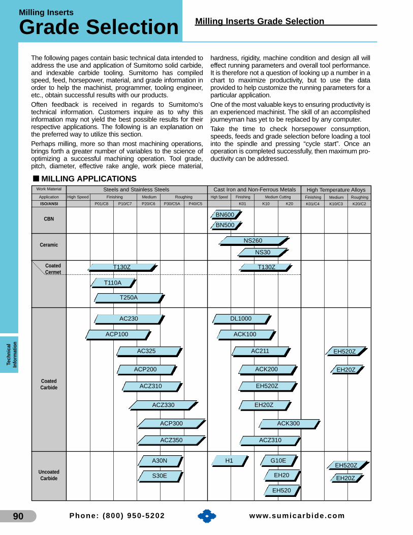
Milling Inserts
Grade SelectionTe
chni
cal
Info
rmat
ion
90
Milling Inserts Grade Selection
Phone: (800) 950-5202 www.sumicarb ide.com
The following pages contain basic technical data intended toaddress the use and application of Sumitomo solid carbide,and indexable carbide tooling. Sumitomo has compiledspeed, feed, horsepower, material, and grade information inorder to help the machinist, programmer, tooling engineer,etc., obtain successful results with our products.Often feedback is received in regards to Sumitomo’stechnical information. Customers inquire as to why thisinformation may not yield the best possible results for theirrespective applications. The following is an explanation onthe preferred way to utilize this section.Perhaps milling, more so than most machining operations,brings forth a greater number of variables to the science ofoptimizing a successful machining operation. Tool grade,pitch, diameter, effective rake angle, work piece material,
hardness, rigidity, machine condition and design all willeffect running parameters and overall tool performance.It is therefore not a question of looking up a number in achart to maximize productivity, but to use the dataprovided to help customize the running parameters for aparticular application.One of the most valuable keys to ensuring productivity isan experienced machinist. The skill of an accomplishedjourneyman has yet to be replaced by any computer.Take the time to check horsepower consumption,speeds, feeds and grade selection before loading a toolinto the spindle and pressing “cycle start”. Once anoperation is completed successfully, then maximum pro-ductivity can be addressed.
Steels and Stainless SteelsFinishing Medium CuttingHigh SpeedApplication
Work Material
Medium Roughing High Speed
CBN
Ceramic
CoatedCermet
CoatedCarbide
UncoatedCarbide
G10E
EH20
EH520
BN500
BN600
T110A
T130Z T130Z
A30N
S30E
Cast Iron and Non-Ferrous Metals
NS30
NS260
T250A
AC230
AC325
ACZ310
AC211
ACP100 ACK100
EH520Z
ACP200 ACK200
EH20Z
ACZ310ACZ350
ACP300
P01/C8ISO/ANSI P10/C7 P20/C6 P30/C5A P40/C5 K01 K10 K20
RoughingMediumFinishing
High Temperature Alloys
K01/C4 K10/C3 K20/C2
ACZ330
DL1000
H1
EH520Z
EH20Z
EH520Z
EH20Z
■ MILLING APPLICATIONS
Finishing
ACK300

91
TechnicalInform
ation
Grade Descriptions/Applications Milling Inserts1. Coated Grades
2. Cermet Grades
Grade Hardness (Hv) T.R.S. (kg/mm 2) Applications
T250A 1430 220 Finish milling of steels and stainless steels
4. CBN
Grade Hardness (Hv) Applications
BN500 3,300-3,500 High speed milling of gray and nodular cast irons
BN600 3,300-3,500 High speed milling of gray cast iron and finishing of exotic materials.
5. Polycrystalline Diamond (PCD)
Grade Hardness (Hv) Applications
DA2200 9,000-10,000 Finishing, roughing and interrupted machining of aluminum and non-ferrous materials
DA200 8,000-10,0000 Milling of non-ferrous alloys and plastics
DA150 10,000-12,0000 Machining of aluminum, copper, wood, rubber, graphite and carbide (soft), plastic, etc.
6. Uncoated Carbide
Grade Grade Hardness T.R.S. (psi) Applications
S30E 91.3 348,000 Milling of steels and stainless steelsC-5A
A30N (A30) 90.6 354,000 Rough turning and milling of steel and stainless steelC3 H1 92.4 352,000 Finishing to semi-finishing of aluminum
G10E 91.0 280,000 Milling of cast iron and aluminumH10E 92.3 284,467 Wiper inserts for cast iron and aluminumEH20 91.0 474,000 Milling of exotic materialsEH520 91.8 436,000 Longer tool life for exotic material milling
Grade Coating Layer Applications Color
ACP100 CVD “Super FF” Coating General to high speed and wet cutting of steels and stainless steels Gold
ACP200 PVD “Super ZX” Coating First choice for general purpose milling of steels and stainless steels Bronze
ACP300 PVD “Super ZX” Coating Very tough grade for steels and stainless steels Bronze
ACK100 CVD “Super FF” Coating High speed grade for milling gray and ductile cast irons Gold
ACK200 CVD “Super FF” Coating General purpose milling of gray and ductile cast irons Gold
ACK300 PVD “Super ZX” Coating General to heavy cutting of gray and ductile cast irons Bronze
EH20Z Double Phase PVD Milling of exotic materials Gold
AC325 Double Phase PVD General purpose milling of steels and stainless steels Gold
AC230 Multi-Phase Al2O3 High speed milling of steels and stainless steels Gold
AC211 Multi-Phase Al2O3 General purpose milling of cast iron Gold
ACZ120 ZX Coating (TIN/AIN) Finish milling of heat treated tool steels and alloys Pink
ACZ310 ZX Coating (TIN/AIN) General purpose milling of cast iron Pink
ACZ330 ZX Coating (TIN/AIN) General purpose milling of steels and stainless steels Pink
ACZ350 ZX Coating (TIN/AIN) General purpose milling of steels and stainless steels Pink
DL1000 Diamond-Like Carbon High speed milling of non-ferrous materials Blue
C2
3. Ceramic Grades
Grade Composition Hardness (Hv) Applications
NS30 Si3N4— Milling of cast iron
NS260 Si3N4 1,750 Milling of cast iron
Phone: (800) 950-5202 www.sumicarb ide.com

Milling InsertsTe
chni
cal
Info
rmat
ion
92
Grade Descriptions/Applications
Phone: (800) 950-5202
■ Grade Descriptions/Applications
■ Coated Grades
Sumitomo Electric Carbide, Inc. continues to introduce new and improved grades for milling. Thepatented “Super ZX” and “Super FF” coatings are featured on our new ACK and ACP series grades. Thistechnology provides our customers with increased tool life and productivity.
With the introduction of our Wave Ballnose Finishing Endmill (WBMF), Sumitomo developed a ZXcoated grade ACZ120 dedicate. The ACZ120 excels in applications involving finish milling of heat treatedtool steels and alloys, and is available only for the WBMF cutter.
Sumitomo’s idea of constant improvement through technology has once again provided the industry witha new style of insert. The Diamond-Like Carbon (DLC) coating on grade DL1000 excels in high speed non-ferrous milling applications due to its extremely hard coating.
These tools added to Sumitomo’s existing milling grades complete the product line, making it easier forthe customer when dealing with difficult applications.
Grade Coating Layer Applications Color
ACP100 CVD “Super FF” Coating General to high speed and wet cutting of steels and stainless steels Gold
ACP200 PVD “Super ZX” Coating First choice for general purpose milling of steels and stainless steels Bronze
ACP300 PVD “Super ZX” Coating Very tough grade for steels and stainless steels Bronze
ACK100 CVD “Super FF” Coating High speed grade for milling grey and ductile cast irons Gold
ACK200 CVD “Super FF” Coating General purpose milling of grey and ductile cast irons Gold
ACK300 PVD “Super ZX” Coating General to heavy cutting of grey and ductile cast irons Bronze
EH20Z Double Phase PVD Milling of exotic materials Gold
AC325 Double Phase PVD General purpose milling of steels and stainless steels Gold
AC230 Multi-Phase Al2O3 High speed milling of steels and stainless steels Gold
AC211 Multi-Phase Al2O3 General purpose milling of cast iron Gold
ACZ120 ZX Coating (TIN/AIN) Finish milling of heat treated tool steels and alloys Pink
ACZ310 ZX Coating (TIN/AIN) General purpose milling of cast iron Pink
ACZ330 ZX Coating (TIN/AIN) General purpose milling of steels and stainless steels Pink
ACZ350 ZX Coating (TIN/AIN) General purpose milling of steels and stainless steels Pink
DL1000 Diamond-Like Carbon High speed milling of non-ferrous materials Blue
www.sumicarb ide.com

Grade Descriptions/Applications
93
Milling Inserts
Phone: (800) 950-5202 www.sumicarb ide.com
TechnicalInform
ation
■ Cermet Grades
Grade Hardness (Hv) T.R.S. (kg/mm 2) Applications
T250A 1430 220 Finish milling of steels and stainless steels
■ Ceramic Grades
Grade Composition Hardness (Hv) Applications
NS30 Si3N4— Milling of cast iron
NS260 Si3N4 1,750 Milling of cast iron
Cermets are a type of cutting tool insert that combine theproperties of ceramic and metal materials in their chemicalmakeup. These tools provide excellent surface finishes andhave a high resistance to adhesion due to their sharp cutting edge.
Sumitomos T250A cermet milling grade exhibits excellenttoughness in finish milling applications. Also, the T250A is agreat economic alternative to coated carbide grades whenmachining steels and stainless steels.
Sumitomo Electric Carbide, Inc. produces superior-qualityceramic cutting tools. These highly reliable tools feature a fine grain size which produces both wear resistance andtoughness.
■ GRADE FEATURESSilicon Nitride Ceramic NS260The ceramic grade NS260 has an extremely fine grainmicrostructure. As a result, it is much more wear resistant tophysical and chemical damage than conventional ceramic grades.
Silicon Nitride Ceramic NS30The ceramic grade NS30 is manufactured with a unique processwhich increases toughness while preserving its wear resistance,creating longer tool life.

Milling InsertsTe
chni
cal
Info
rmat
ion
94
Milling Inserts
Phone: (800) 950-5202 www.sumicarb ide.com
■ Uncoated Carbide
Grade Grade Hardness T.R.S. (psi) Applications
S30E 91.3 348,000 Milling of steels and stainless steelsC-5A
A30N (A30) 90.6 354,000 Rough turning and milling of steel and stainless steelC3 H1 92.4 352,000 Finishing to semi-finishing of aluminum
G10E 91.0 280,000 Milling of cast iron and aluminumH10E 92.3 284,467 Wiper inserts for cast iron and aluminumEH20 91.0 474,000 Milling of exotic materialsEH520 91.8 436,000 Longer tool life for exotic material milling
C2
Sumitomo Electric Carbide, Inc’s research and development of tungsten carbide grades began in 1927.Since then, we have greatly improved and refined our grades to meet the needs of our customers today.
Our latest uncoated carbide milling grade is the EH520. This extremely tough grade outperforms thecompetition in applications involving exotic materials.

CBN Milling Grades
95
CBN
Milling Grades
Phone: (800) 950-5202 www.sumicarb ide.com
TechnicalInform
ation
Sumitomo Electric Carbide, Inc. is a world leader in the development of CBN cutting tool materials and their applications. For you, this means increased productivity, better surface finish, and an ability to hold closertolerances with longer tool life. Sumitomo offers products, sizes and grades available nowhere else.
BN500, BN600, and BN700 are three grades produced by Sumitomo and dedicated to machining cast irons. Theirwear resistance and high speed capability increases tool life and productivity.
■ Cubic Boron Nitride (CBN) Grades
Grades Features Applications
• High CBN content• Superior thermal conductivity and
adhesion resistance• Milling geometries available
High speed milling of gray cast iron
Hardness(Hv)
3900|
4200
95|
110
T.R.S.(kg/mm2)
BN600
• CBN sintered with ceramic binder material• Good thermal and wear resistance
Medium speed (,2000 sfm) milling of gray cast iron3300|
3500
100|
110
BN500
PCBN is generally classified into two groups according tothe material microstructure. The CBN particles of the firsttype are bonded together directly without an additional bindermaterial (BN600/BN700). This type of CBN contains a largepercentage of CBN and is thus extremely hard.
SUMIBORON, representative of the second type of PCBNmaterials, consists of CBN particles bonded together by aceramic binder (BN500). The bonding strength is very highand thus is very wear-resistant and tough.
Microstructure Features Grades
CBN particlesare bonded toeach other
BN600BN700
BN500
CBN particlesare bonded bya ceramicbinder
BN Finish MillFMU Milling Cutter
Milling Cutters by Request

PCD
Milling GradesTe
chni
cal
Info
rmat
ion
96
PCD Milling Grades
Phone: (800) 950-5202 www.sumicarb ide.com
FAM Milling Cutter SAM Milling CutterRF Milling Cutter
Milling Cutters by Request
Since the introduction of SUMIDIA DA polycrys-talline diamond (PCD) blanks in 1978, Sumitomo hascontinually developed and expanded the product lineto offer finished inserts in a wide range of grades,shapes and sizes. SUMIDIA inserts consist of a layerof fine grain synthetic diamond crystals bonded to atungsten carbide substrate which is securely brazedinto the pocket of a standard size insert. A highdegree of diamond to diamond bonding is achievedby an ultra high pressure-temperature process. Thiscrystal to crystal bonding provides exceptionalhardness and abrasion resistance.
Our closely controlled manufacturing processproduces unequaled consistency resulting insuperior tool edge quality.
SUMIDIA DA inserts and wipers are replacingtungsten carbide and natural diamond cutting tools on a worldwide basis. Use of SUMIDIA DA gradeswill provide dramatically increased tool life, the abilityto hold closer part tolerance, and improved surface finish.
New technological advances have given the industry a new style of PCD insert. The optimum sizeof PCD used in NF-DA2200 offers a less expensivealternative when machining non-ferrous materials.
Average Diamondcrystal size (microns)
Hardness (Hv)
T.R.S. (kg/mm2)
ProductDescription
Applications:
5
10,000-12,000
200
0.5
9,000-10,000
250
0.5
8,000-10,000
220
• Fine grain diamond
• High abrasion resistance
• High density sinteredmaterial made of ultra-micro diamond particles
• Superior hardness andwear resistance withsharp edge
• Ultra-fine grain structure
• Superior tool edgesharpness and toughness
■ Polycrystalline Diamond (PCD) Grades
Grade DA2200 DA150 DA200
• High Silicon Aluminum
• Copper
•Fiberglass
• Hard Rubber
• Graphite Epoxy
•Wood
• Carbon
• High Silicon Aluminum
• Copper
• Fiberglass
• Hard Rubber
• Graphite Epoxy
• Wood
• Aluminum Alloys
(finish, rough andinterrupted)
• Plastics
• Wood
• Aluminum applicationswhere low microfinish
is needed

Indexable Milling Cutters
97
Indexable
Milling Cutters
Phone: (800) 950-5202 www.sumicarb ide.com
TechnicalInform
ation
■ Illustration of Technical Terms
Hole DiameterWidth of Key Way
Lead Angle
Cutting EdgeInclinationAngle
Setting Ring
Depth of Key Way
Axial Rake Angle
Cutter Body
Back LocatingFace
Chip Pocket
Bolt
Insert
Front Relief Angle
TrueRake Angle
Radial Relief
Section A
Section A
Wiper Flat
FaceAngle
Major Cutting Edge
Chamfered Corner
Diameter of Cutter
Locator
Setting Ring
Clamp
Radial Rake Angle
External Diameter of Boss
External Diameter of Cutter Body
Overall Height
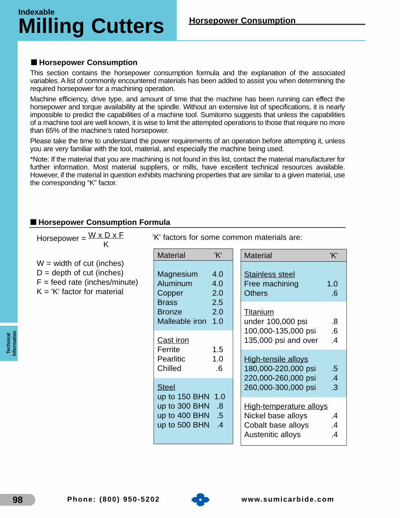
Indexable
Milling CuttersTe
chni
cal
Info
rmat
ion
98
Horsepower Consumption
Phone: (800) 950-5202 www.sumicarb ide.com
■ Horsepower Consumption Formula
Horsepower = W x D x FK
W = width of cut (inches)D = depth of cut (inches)F = feed rate (inches/minute)K = 'K' factor for material
'K' factors for some common materials are:
Material 'K'
Magnesium 4.0Aluminum 4.0Copper 2.0Brass 2.5Bronze 2.0Malleable iron 1.0
Cast ironFerrite 1.5Pearlitic 1.0Chilled .6
Steelup to 150 BHN 1.0up to 300 BHN .8up to 400 BHN .5up to 500 BHN .4
Material 'K'
Stainless steelFree machining 1.0Others .6
Titaniumunder 100,000 psi .8100,000-135,000 psi .6135,000 psi and over .4
High-tensile alloys180,000-220,000 psi .5220,000-260,000 psi .4260,000-300,000 psi .3
High-temperature alloysNickel base alloys .4Cobalt base alloys .4Austenitic alloys .4
This section contains the horsepower consumption formula and the explanation of the associatedvariables. A list of commonly encountered materials has been added to assist you when determining therequired horsepower for a machining operation.
Machine efficiency, drive type, and amount of time that the machine has been running can effect thehorsepower and torque availability at the spindle. Without an extensive list of specifications, it is nearlyimpossible to predict the capabilities of a machine tool. Sumitomo suggests that unless the capabilitiesof a machine tool are well known, it is wise to limit the attempted operations to those that require no morethan 65% of the machine’s rated horsepower.
Please take the time to understand the power requirements of an operation before attempting it, unlessyou are very familiar with the tool, material, and especially the machine being used.
*Note: If the material that you are machining is not found in this list, contact the material manufacturer forfurther information. Most material suppliers, or mills, have excellent technical resources available.However, if the material in question exhibits machining properties that are similar to a given material, usethe corresponding “K” factor.
■ Horsepower Consumption
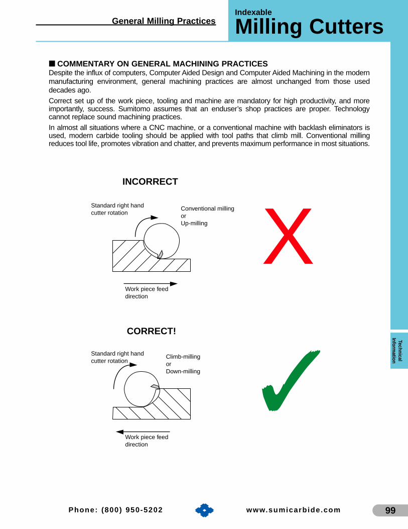
General Milling Practices
99
Indexable
Milling Cutters
Phone: (800) 950-5202 www.sumicarb ide.com
TechnicalInform
ation
■ COMMENTARY ON GENERAL MACHINING PRACTICESDespite the influx of computers, Computer Aided Design and Computer Aided Machining in the modernmanufacturing environment, general machining practices are almost unchanged from those useddecades ago.
Correct set up of the work piece, tooling and machine are mandatory for high productivity, and moreimportantly, success. Sumitomo assumes that an enduser’s shop practices are proper. Technologycannot replace sound machining practices.
In almost all situations where a CNC machine, or a conventional machine with backlash eliminators isused, modern carbide tooling should be applied with tool paths that climb mill. Conventional millingreduces tool life, promotes vibration and chatter, and prevents maximum performance in most situations.
INCORRECT
Work piece feeddirection
Standard right handcutter rotation
Climb-millingorDown-milling
CORRECT!
Work piece feeddirection
Standard right handcutter rotation
Conventional millingorUp-milling X
✓

Indexable
Milling CuttersTe
chni
cal
Info
rmat
ion
100
Lead Angle Effect
Phone: (800) 950-5202 www.sumicarb ide.com
The lead angle effect is a commonly known phenomenon in tool design. As the lead angle of a tool (theangle at which the insert is rotated away from its axial center line) increases, the actual thickness of theproduced chip decreases from the programmed amount. This allows us to take advantage of increasedfeed rates over standard zero degree (90 degree shoulder) lead tools.
By comparing the following lead angle figures, it is possible to increase the actual feed rate up to 30%over the suggested numbers (depending on the type of tool), thus increasing productivity.
Tool Lead Angle Percentage of chip thickness fromprogrammed feed rate
15 degrees 96%
20 degrees 94%
30 degrees 86%
45 degrees 71%
To simplify this calculation we have included a chart that allows easy determination of programmed feedper tooth by choosing desired feed per tooth and then following the column down to the row that matchesthe lead angle of the tool that is being used.
Example: Find the programmed feed per tooth for a UFO cutter (45 degree lead angle), when thedesired feed per tooth is 0.006 IPT.
Answer: Programmed feed per tooth = 0.0085 IPT
Programmed Feed Per Tooth vs. Desired Feed Per Tooth
0.004 0.005 0.006 0.007 0.008 0.009 0.010 0.011 0.012
15 0.0042 0.0052 0.0063 0.0073 0.0083 0.0094 0.0104 0.0115 0.0125
20 0.0043 0.0053 0.0064 0.0074 0.0085 0.0096 0.0106 0.0117 0.0128
30 0.0047 0.0061 0.0070 0.0081 0.0093 0.0105 0.0116 0.0128 0.0140
45 0.0057 0.0075 0.0085 0.0099 0.0113 0.0127 0.0141 0.0156 0.0170
Desired Feed Per Tooth (IPT)
Programmed Feed Per Tooth (IPT)
■ Lead Angle Effect
Tool Lead
Angle

Radial Chip Thinning
101
Indexable
Milling Cutters
Phone: (800) 950-5202 www.sumicarb ide.com
TechnicalInform
ation
■ Radial Chip ThinningJust as the axial rake of a cutting tool can alter the actual chip thickness, so can radial chip thinning.This occurs whenever the radial width of cut is less than 1/2 the cutter diameter. This is commonlyfound when making periphery cuts while end milling.Since both tool life and productivity rely on maintaining full chip thickness, it is important to compensatefor this scenario. Rather than using the mathematical process to arrive at a programmed feed rate, wehave included the following chart.
To use this chart it is necessary to have the following information:
1) Desired feed per tooth (as taken from the end mill speed and feed section)2) Cutter diameter3) Radial width of cut
The first step is to divide the radial width of cut by the cutter diameter and find the closest value in thefirst column on the left. Next find the desired feed per tooth at the top of the chart and follow that columndown to the row that was found in the first step. This will be the programmed feed per tooth.
Example: 1.00˝ diameter end mill Answer: Dividing 0.020˝ by 1.00˝=0.0200.020˝ radial width of cut0.004˝ desired feed per tooth
Finding 0.020 in the first column on the left, and then the 0.004˝ desired feed per tooth at the top, wefind where the two meet and obtain 0.014˝ programmed feed per tooth.
This results in a large increase in the feed rate. If we use these factors for a four flute tool at 2292 RPM,we have a feed rate of 128 IPM (2292 RPM x 0.014 IPT x 4 Flutes) versus 37 IPM (2292 RPM x 0.004IPT x 4 Flutes) that might have otherwise been programmed.
As you can see from the illustration below, as radial depth increases, so does chip thickness until wereach 50% of the cutting diameter. At this point we have full, programmed chip load.
0.004 0.005 0.006 0.007 0.008 0.009 0.010 0.011 0.012
WOC/Dia.0.005 0.0280 0.0350 0.0420 0.0490 0.0560 0.0630 0.0700 0.0770 0.08400.010 0.0200 0.0250 0.0300 0.0350 0.0400 0.0450 0.0500 0.0550 0.06000.015 0.0164 0.0205 0.0246 0.0287 0.0328 0.0369 0.0410 0.0451 0.04920.020 0.0140 0.0175 0.0210 0.0245 0.0280 0.0315 0.0350 0.0385 0.04200.025 0.0128 0.0160 0.0192 0.0224 0.0256 0.0288 0.0320 0.0352 0.03840.030 0.0116 0.0145 0.0174 0.0203 0.0232 0.0261 0.0290 0.0319 0.03480.035 0.0108 0.0135 0.0162 0.0189 0.0216 0.0243 0.0270 0.0297 0.03240.040 0.0100 0.0125 0.0150 0.0175 0.0200 0.0225 0.0250 0.0275 0.03000.060 0.0084 0.0105 0.0126 0.0147 0.0168 0.0189 0.0210 0.0231 0.02520.080 0.0072 0.0090 0.0108 0.0126 0.0144 0.0162 0.0180 0.0198 0.02160.120 0.0060 0.0075 0.0090 0.0105 0.0120 0.0135 0.0150 0.0165 0.01800.200 0.0052 0.0065 0.0078 0.0091 0.0104 0.0117 0.0130 0.0143 0.01560.300 0.0044 0.0055 0.0066 0.0077 0.0088 0.0099 0.0110 0.0121 0.0132
Desired Feed Per Tooth (IPT)
Programmed Feed Per Tooth (IPT)
Radial chipthickness
■ Radial Chip Thinning Compensation

Indexable Milling Cutters
Speeds & FeedsTe
chni
cal
Info
rmat
ion
102
Speeds and Feeds
Phone: (800) 950-5202 www.sumicarb ide.com
■ Indexable Milling CuttersThe following chart contains a list of commonly encounteredmaterials, suggested surface speeds, and chip loads (ipt). It isimportant to note that this is not a complete listing of allmaterials used in industry. It should be considered a guide tobe used when initially setting up a new application, and as aresource for better understanding Sumitomo’s cutting toolgrades.
As there are tremendous variations in the capabilities andperformance of machine tools, and variations in work piecematerials as well, individual results can vary considerably.This is where the trained eye of an advanced machinist, orApplications Engineer can markedly improve tool life and pro-ductivity. Sumitomo has Sales and Applications personnel forjust this purpose. When in doubt of the correct selection of atool type or grade your sales person can assist in achievingwinning results.
When applying carbide grades it is important to understandthe characteristics of the different types that Sumitomo offers.A few minutes spent looking at the grade comparison chart onpage 83 will shed some light on the differences betweenthem. Coated grades in most situations will provide anincrease in tool life, and are the preferred choice in themajority of industry today. Whether coated or not, the harder
grades will tend to be more wear resistant, but at the cost oftoughness. They generally will be the best choice for easier tomachine materials, but will sacrifice tool life in situations thatlack machine and/or part rigidity.
When programming an operation with a new grade, or anunfamiliar material, it is wise to start at the low end of thespeed and feed range and then work towards the upperranges. Make any changes one at a time so that the resultscan be examined accurately.
It is worth noting that modern cutting tool materials will oftenencounter as many problems when run too slowly, or whenprogrammed at insufficient feed rates as they can when runtoo fast. Since most of our inserts have been manufacturedwith edge preparations, feeds below .002, or .003 IPT maydiminish tool life. Also, they must have enough speed tooperate correctly. Cutting tools require an elevatedtemperature to perform without chip weld. Proper cuttingparameters will insure the heat that is generated will bedeposited into, and removed with the chip. Most situationsinvolving steels and alloys the best results are obtained withan air blast versus coolant. In applications cutting exoticalloys, aluminum, brass, grey iron, etc., commonly employcoolant.
ACP200 721-1213 675-1180 600-1125 .006-.0135ACP100 775-1310 725-1275 675-1225 .006-.0125ACZ330 650-1050 620-1020 575-900 .005-.0125ACZ310 675-1075 650-1025 550-950 .004-.0085AC230 685-1125 650-1050 525-950 .004-.008
T250A 700-1310 675-1200 575-1000 .0035-.0075ACP300 675-1075 650-1025 525-925 .006-.014ACZ350 650-1050 600-1000 500-925 .005-.0125AC325 625-900 585-850 500-800 .004-.011A30N 600-850 575-825 475-750 .005-.011
ACP200 725-1300 700-1250 675-1200 .006-.0135ACP100 750-1325 725-1275 675-1225 .006-.0135AC230 725-1200 700-1150 675-1100 .004-.008
ACZ330 675-1125 650-1050 650-1000 .005-.0125T250A 825-1450 825-1375 775-1300 .0035-.0085
ACZ310 675-1125 650-1100 650-1075 .004-.0085AC325 650-950 625-925 625-900 .004-.011
ACP300 675-1075 650-1050 650-1025 .006-.014ACZ350 675-1075 650-1050 650-1025 .005-.0125
A30N 650-950 625-900 600-875 .005-.011ACP200 575-950 550-925 500-875 .006-.012ACZ330 525-900 500-850 475-800 .005-.0105ACP100 600-975 575-950 550-900 .006-.011ACP300 575-950 550-925 500-875 .006-.012ACZ350 450-900 425-850 525-925 .005-.0115AC325 475-725 425-750 475-775 .004-.010
T250A 450-950 425-850 400-825 .0035-.0075ACZ310 500-925 475-900 450-875 .004-.0075AC230 550-1000 500-900 500-925 .004-.008A30N 400-775 375-575 450-925 .005-.011
Material Hardness Insert Grade Speed (SFM) based upon Depth of Cut Inch Feed (IPT)Carbide Cermet Diamond Ceramic .002-.050 .050-.125 .125 and over
Low and mediumcarbon steels
1008,1010,10181020,1025 etc.
,250 Bhn
Free machiningsteels and alloys
Freemax 15Freemax 4512L14, etc.
,250 Bhn
Medium-highcarbon steels
1040,10451055,1080
50100,5110052100,M-50
,250 Bhn
*NOTE: THESE SPEEDS ARE BASED ON 2/3 THE DIAMETER OF THE CUTTER ENGAGED.

Speeds and Feeds
103
Indexable Milling Cutters
Speeds & Feeds
Phone: (800) 950-5202 www.sumicarb ide.com
TechnicalInform
ation
ACP200 550-900 525-900 500-875 .006-.0115ACZ330 550-875 525-850 500-825 .0045-.0105ACP100 600-875 575-950 550-900 .006-.0095ACP300 525-875 500-825 475-800 .006-.0115ACZ350 525-850 500-825 500-800 .0045-.011AC325 500-800 500-800 475-775 .0045-.009
T250A 450-950 425-850 400-825 .0035-.0075ACZ310 550-875 525-850 500-800 .004-.008AC230 575-900 550-875 525-850 .004-.008A30N 475-750 450-725 425-700 .005-.009
ACP200 450-820 435-790 425-750 .0047-.011ACZ330 450-790 425-750 400-725 .0045-.0095ACP300 450-820 425-790 400-725 .0047-.012ACP100 475-820 450-790 425-750 .0047-.010ACZ350 450-725 435-710 425-700 .005-.010AC325 375-700 360-685 350-675 .004-.009T250A 450-650 425-600 250-550 .0039-.0079
ACP200 425-750 400-725 375-690 .0045-.010ACZ330 400-750 400-725 400-690 .0045-.0095ACP300 420-700 420-695 375-685 .0047-.012ACP100 400-775 400-735 400-700 .004-.009ACZ350 400-700 420-695 410-685 .005-.009AC325 350-675 345-670 335-660 .004-.008A30N 325-625 320-620 310-610 .005-.0085
ACP200 325-650 300-625 300-590 .0045-.0095ACP100 325-650 300-625 300-590 .003-.007ACZ330 400-750 400-725 400-690 .0045-.0095ACZ310 325-650 300-625 300-590 .003-.007EH20Z 325-650 300-625 300-590 .003-.007
ACP300 525-840 515-820 250-800 .004-.012ACP200 535-850 520-830 275-820 .004-.011ACZ350 525-840 515-820 250-800 .005-.010ACZ330 535-850 520-830 275-820 .0045-.009ACZ310 550-875 540-850 275-835 .0035-.0075T250A 550-950 500-900 .0035-.0075
ACP300 425-740 275-825 250-800 .004-.012ACP200 325-875 300-850 275-825 .004-.011ACZ350 425-740 415-720 175-675 .0035-.009ACZ330 435-750 420-720 175-700 .0035-.008EH20Z 400-750 400-725 375-700 .0035-.007
ACP300 300-850 275-825 250-800 .004-.012ACP200 325-875 300-850 275-825 .004-.011ACZ350 300-850 275-825 250-800 .0035-.009ACZ330 325-875 300-850 275-825 .0035-.009EH20Z 300-750 300-725 275-775 .0035-.0075T250A 650-950 600-900 .0035-.0075EH520 100-300 100-275 100-265 .003-.008EH20Z 100-300 100-275 100-265 .003-.008
ACZ310 100-300 100-275 100-265 .003-.007EH20Z 80-180 75-165 70-155 .003-.0075
ACK200 100-160 70-150 60-135 .003-.0075ACK300 100-160 70-150 60-135 .004-.0075ACZ310 80-160 70-150 60-135 .0025-.0065
G10E 70-125 60-110 50-100 .003-.007
Material Hardness Insert Grade Speed (SFM) based upon Depth of Cut Inch Feed (IPT)Carbide Cermet Diamond Ceramic .002-.050 .050-.125 .125 and over
Medium carbonalloy steels
4140, 43405130, 8620
,250 Bhn
Tool steels
D2, H13, S7, etc.
,250 Bhn
Bhn 220-350
.33 Hrc
,250 Bhn
.250 Bhn
Martensitic andFerritic stainless
steels414, 416, 430, 440
,250 Bhn
Austenitic andPrecipitation hardening
stainless steels303, 304, 316,
321, etc.
Titanium alloy
Exotic alloysInconel, Hastalloy
Waspalloy, etc.
*NOTE: THESE SPEEDS ARE BASED ON 2/3 THE DIAMETER OF THE CUTTER ENGAGED.

104 Phone: (800) 950-5202 www.sumicarb ide.com
Indexable Milling Cutters
Speeds & FeedsTe
chni
cal
Info
rmat
ion
Speeds and Feeds
ACK100 700-1250 625-1125 590-925 .004-.014ACK200 700-1050 625-925 590-900 .004-.014ACK300 600-950 575-875 550-850 .004-.014K245R2 700-1050 625-925 590-900 .004-.014ACZ310 650-975 625-925 590-900 .004-.0095AC211 600-900 550-875 525-850 .004-.0085G10E 500-800 475-750 425-725 .004-.010
NS260 1900-3500 1800-3300 1650-3200 .0025-.007NS30 1800-3500 1800-3300 1650-3200 .0025-.0065
ACK100 600-1000 625-925 590-850 .004-.014ACK200 600-950 525-825 490-800 .004-.014ACK300 500-850 475-775 450-750 .004-.014K245R2 600-950 525-825 490-800 .004-.014ACZ310 550-875 525-825 490-800 .004-.0085AC211 500-800 450-775 425-750 .0035-.008G10E 400-700 375-650 325-625 .004-.009
NS260 1700-3300 1600-3100 1450-3000 .0025-.006NS30 1600-3200 1500-3000 1350-2900 .0025-.0055
ACK200 600-925 550-875 490-800 .004-.012ACK100 600-1000 625-925 590-850 .004-.012ACK300 550-825 550-825 450-750 .004-.012K235R2 650-925 600-875 490-800 .004-.012ACZ310 650-925 600-875 490-800 .004-.0085AC211 500-800 475-750 450-675 .0035-.0075
NS260 1700-3300 1600-3100 1450-3000 .0025-.006DA150 3500-10000 3200-8000 2800-6000 .003-.006
DL1000 1500-4500 1475-4200 1275-4100 .004-.014H1 1500-3800 1300-3700 1200-3600 .004-.014
G10E 1250-3500 1150-3100 1050-2900 .004-.015DA150 1800-6500 1700-5500 1600-5000
DL1000 1075-3100 950-2950 850-2500 .0035-.0085H1 1000-3000 900-2500 800-2000 .0035-.0085
G10E 900-2900 800-2400 700-1900 .0035-.009
Material Hardness Insert Grade Speed (SFM) based upon Depth of Cut Inch Feed (IPT)Carbide Cermet Diamond Ceramic .002-.050 .050-.125 .125 and over
Grey Cast Iron
,250 Bhn
Ductile Iron
.250 Bhn
,320 Bhn
Aluminum, Brass,Copper
High SiliconeAluminum
*NOTE: THESE SPEEDS ARE BASED ON 2/3 THE DIAMETER OF THE CUTTER ENGAGED.

IndexSLP1250 . . . . . . . . . . . . . . . . . . . . . . . . . .66SLP1250-C . . . . . . . . . . . . . . . . . . . . . . . .66SLP1250MC-SPAN . . . . . . . . . . . . . . . . . .67SLP1250N-C . . . . . . . . . . . . . . . . . . . . . . .66SLP1250N-S . . . . . . . . . . . . . . . . . . . . . . .66SLP1250N-N . . . . . . . . . . . . . . . . . . . . . . .66SLP2000 . . . . . . . . . . . . . . . . . . . . . . . . . .67SLP2000-C . . . . . . . . . . . . . . . . . . . . . . . .67SLP2000MC-SPAN . . . . . . . . . . . . . . . . . .67SLP2000N-C . . . . . . . . . . . . . . . . . . . . . . .67SLP2000N-S . . . . . . . . . . . . . . . . . . . . . . .67SLP2000N-N . . . . . . . . . . . . . . . . . . . . . . .67SMHK . . . . . . . . . . . . . . . . . . . . . . . . . . . .84SNEX . . . . . . . . . . . . . . . . . . . . . . . . . . . .44SNG . . . . . . . . . . . . . . . . . . . . . . . . . . . . .53SNMN . . . . . . . . . . . . . . . . . . . . . . . . . . . .53SPCH . . . . . . . . . . . . . . . . . . . . . . . . . .56-57SPG . . . . . . . . . . . . . . . . . . . . . . . . . . .56-57SPMN . . . . . . . . . . . . . . . . . . . . . . . . .56-57SSUP-Z . . . . . . . . . . . . . . . . . . . . . . . . . . .12SSI . . . . . . . . . . . . . . . . . . . . . . . . . . . . . .13SSI-C . . . . . . . . . . . . . . . . . . . . . . . . . . . .13
T
TECN . . . . . . . . . . . . . . . . . . . . . . .50-51,54TEEN . . . . . . . . . . . . . . . . . . . . . . .50-51,54TEKN . . . . . . . . . . . . . . . . . . . . . . .50-51,54TG-1 . . . . . . . . . . . . . . . . . . . . . . . . . . . . .70TG-3 . . . . . . . . . . . . . . . . . . . . . . . . . . . . .70TG-NUT . . . . . . . . . . . . . . . . . . . . . . . . . .70TG-SPAN . . . . . . . . . . . . . . . . . . . . . . . . .70TG050 . . . . . . . . . . . . . . . . . . . . . . . . . . . .69TG075 . . . . . . . . . . . . . . . . . . . . . . . . . . . .69TG100 . . . . . . . . . . . . . . . . . . . . . . . . . . . .69TG100-C . . . . . . . . . . . . . . . . . . . . . . . . . .69TPC . . . . . . . . . . . . . . . . . . . . . . . . . . . . . .55TPCH . . . . . . . . . . . . . . . . . . . . . . . . . . . .55TPG . . . . . . . . . . . . . . . . . . . . . . . . . . . . .55TPMN . . . . . . . . . . . . . . . . . . . . . . . . . . . .55
U
UFO-R8 . . . . . . . . . . . . . . . . . . . . . . . . . .46UFO . . . . . . . . . . . . . . . . . . . . . . . . . . . . .48UFOF . . . . . . . . . . . . . . . . . . . . . . . . . . . .47UFOR . . . . . . . . . . . . . . . . . . . . . . . . . . . .49UW . . . . . . . . . . . . . . . . . . . . . . . . . . . .46-48
W
WBMF . . . . . . . . . . . . . . . . . . . . . . . . . . . .35WBMR . . . . . . . . . . . . . . . . . . . . . . . . .32-33WEM . . . . . . . . . . . . . . . . . . . . . . . . . .25-26WEM-EX . . . . . . . . . . . . . . . . . . . . . . .25-26WEX-E . . . . . . . . . . . . . . . . . . . . . . . . .20-22WEX-F . . . . . . . . . . . . . . . . . . . . . . . . .21,23WEX-R . . . . . . . . . . . . . . . . . . . . . . . . .21,23WEXC-R . . . . . . . . . . . . . . . . . . . . . . . . . .23WFMC . . . . . . . . . . . . . . . . . . . . . . . . . . . .43WFMF . . . . . . . . . . . . . . . . . . . . . . . . . . . .43WGC-EW . . . . . . . . . . . . . . . . . . . . . . . . .38WGC-R . . . . . . . . . . . . . . . . . . . . . . . . . . .39WGC-RS . . . . . . . . . . . . . . . . . . . . . . . . . .38WGC-SR . . . . . . . . . . . . . . . . . . . . . . . . . .37WGC-WR . . . . . . . . . . . . . . . . . . . . . . . . .37WGCF-R . . . . . . . . . . . . . . . . . . . . . . . . ..39WGCF-RS . . . . . . . . . . . . . . . . . . . . . . . . .38WGCF-SR . . . . . . . . . . . . . . . . . . . . . . . . .37WMM . . . . . . . . . . . . . . . . . . . . . . . . . . . .28WRCS . . . . . . . . . . . . . . . . . . . . . . . . . . . .38WRCW . . . . . . . . . . . . . . . . . . . . . . . . . . .41WRM . . . . . . . . . . . . . . . . . . . . . . . . . .29-30WRM-H . . . . . . . . . . . . . . . . . . . . . . . . . . .30
X
XDMT . . . . . . . . . . . . . . . . . . . . . . . . . . . .43
Z
ZNMT . . . . . . . . . . . . . . . . . . . . . . . . . .32-33ZPGU . . . . . . . . . . . . . . . . . . . . . . . . . . . .35
H
HSI . . . . . . . . . . . . . . . . . . . . . . . . . . . . . .12HSI-C . . . . . . . . . . . . . . . . . . . . . . . . . . . .12HSK63-EMH . . . . . . . . . . . . . . . . . . . . . . .77HSK63-SLP . . . . . . . . . . . . . . . . . . . . . . .64HSK63-SMH . . . . . . . . . . . . . . . . . . . . . . .82HSK100-EMH . . . . . . . . . . . . . . . . . . . . . .77HSK100-SLP . . . . . . . . . . . . . . . . . . . . . .64HSK100-SMH . . . . . . . . . . . . . . . . . . . . . .82
K
KT20-EMH . . . . . . . . . . . . . . . . . . . . . . . .77KT20-SMH . . . . . . . . . . . . . . . . . . . . . . . .82
M
MS . . . . . . . . . . . . . . . . . . . . . . . . . . . . . .45MZBI . . . . . . . . . . . . . . . . . . . . . . . . . . . . .16MZBI-C . . . . . . . . . . . . . . . . . . . . . . . . . . .16MZI . . . . . . . . . . . . . . . . . . . . . . . . . . .14-15MZI-C . . . . . . . . . . . . . . . . . . . . . . . . . .14-15MZM . . . . . . . . . . . . . . . . . . . . . . . . . .14-15MZM-C . . . . . . . . . . . . . . . . . . . . . . . . .14-15
N
NF-SDC . . . . . . . . . . . . . . . . . . . . . . . . . .52NF-SECW . . . . . . . . . . . . . . . . . . . . . .37-39NF-TEEN . . . . . . . . . . . . . . . . . . . .50-51,54NMTB30-EMH . . . . . . . . . . . . . . . . . . . . .78NMTB30-SMH . . . . . . . . . . . . . . . . . . . . .83NMTB40-EMH . . . . . . . . . . . . . . . . . . . . .78NMTB40-ER . . . . . . . . . . . . . . . . . . . . . . .71NMTB40-SLP . . . . . . . . . . . . . . . . . . . . . .64NMTB40-SMH . . . . . . . . . . . . . . . . . . . . .83NMTB50-FMH . . . . . . . . . . . . . . . . . . . . . .83NMTB50-SLP . . . . . . . . . . . . . . . . . . . . . .64NMTB50-SMH . . . . . . . . . . . . . . . . . . . . .83NW . . . . . . . . . . . . . . . . . . . . . . . . . . . . . .53
Q
QPMT . . . . . . . . . . . . . . . . . . . . . . . . .41-42
R
R8-3 . . . . . . . . . . . . . . . . . . . . . . . . . . . . .77R8-5 . . . . . . . . . . . . . . . . . . . . . . . . . . . . .82RGMN . . . . . . . . . . . . . . . . . . . . . . . . . . . .49RSS . . . . . . . . . . . . . . . . . . . . . . . . . . . . .79
S
S10-EMHE . . . . . . . . . . . . . . . . . . . . . . . .79S75-EMHE . . . . . . . . . . . . . . . . . . . . . . . .79SDC . . . . . . . . . . . . . . . . . . . . . . . . . . . . .52SDEW . . . . . . . . . . . . . . . . . . . . . . . . . . . .45SDKN . . . . . . . . . . . . . . . . . . . . . . . . . . . .59SDMR . . . . . . . . . . . . . . . . . . . . . . . . . . . .59SDMW . . . . . . . . . . . . . . . . . . . . . . . . . . .45SDP . . . . . . . . . . . . . . . . . . . . . . . . . . . . .44SEC . . . . . . . . . . . . . . . . . . . . . . . . . . . . .58SEET . . . . . . . . . . . . . . . . . . . . . . . . . .37-39SEKN . . . . . . . . . . . . . . . . . . . . . . . . . . . .58SEMR . . . . . . . . . . . . . . . . . . . . . . . . . . . .58SEMT . . . . . . . . . . . . . . . . . . . . . . . . . .37-39SFEN . . . . . . . . . . . . . . . . . . . . . . . . . .46-48SFKN . . . . . . . . . . . . . . . . . . . . . . . . . .46-48SFKR . . . . . . . . . . . . . . . . . . . . . . . . . .46-48SLP750 . . . . . . . . . . . . . . . . . . . . . . . . . . .65SLP750-C . . . . . . . . . . . . . . . . . . . . . . . . .65SLP750MC-SPAN . . . . . . . . . . . . . . . . . . .67SLP750N-C . . . . . . . . . . . . . . . . . . . . . . . .65SLP750N-S . . . . . . . . . . . . . . . . . . . . . . . .65SLP750N-N . . . . . . . . . . . . . . . . . . . . . . . .65SLP1000 . . . . . . . . . . . . . . . . . . . . . . . . . .66SLP1000-C . . . . . . . . . . . . . . . . . . . . . . . .66SLP1000MC-SPAN . . . . . . . . . . . . . . . . . .67SLP1000N-C . . . . . . . . . . . . . . . . . . . . . . .66SLP1000N-S . . . . . . . . . . . . . . . . . . . . . . .66SLP1000N-N . . . . . . . . . . . . . . . . . . . . . . .66
NUMERICAL
30-SCFX . . . . . . . . . . . . . . . . . . . . . . . . . .8740-SCFX . . . . . . . . . . . . . . . . . . . . . . . . . .8750-SCFX . . . . . . . . . . . . . . . . . . . . . . . . . .87
A
APET . . . . . . . . . . . . . . . . . . . . .25-26,28-30APMT . . . . . . . . . . . . . . . . . . . .25-26,28-30APG . . . . . . . . . . . . . . . . . . . . . . . . . . . . .52APW . . . . . . . . . . . . . . . . . . . . . . . . . . . . .52AXMT . . . . . . . . . . . . . . . . . . . . . . . . . .20-23
B
B-TOOL SET . . . . . . . . . . . . . . . . . . . . . .87BT30-ER . . . . . . . . . . . . . . . . . . . . . . . . . .71BT30-SLP . . . . . . . . . . . . . . . . . . . . . . . . .64BT30-TG . . . . . . . . . . . . . . . . . . . . . . . . . .68BT40-EMH . . . . . . . . . . . . . . . . . . . . . . . .76BT40-ER . . . . . . . . . . . . . . . . . . . . . . . . . .71BT40-SLP . . . . . . . . . . . . . . . . . . . . . . . . .64BT40-SMH . . . . . . . . . . . . . . . . . . . . . . . .81BT40-TG . . . . . . . . . . . . . . . . . . . . . . . . . .68BT50-EMH . . . . . . . . . . . . . . . . . . . . . . . .76BT50-ER . . . . . . . . . . . . . . . . . . . . . . . . . .71BT50-FMH . . . . . . . . . . . . . . . . . . . . . . . .81BT50-SLP . . . . . . . . . . . . . . . . . . . . . . . . .64BT50-SMH . . . . . . . . . . . . . . . . . . . . . . . .81
C
C-TOOL SET . . . . . . . . . . . . . . . . . . . . . .87CHE . . . . . . . . . . . . . . . . . . . . . . . . . . .50-51CHG . . . . . . . . . . . . . . . . . . . . . . . . . . . . .54CPG . . . . . . . . . . . . . . . . . . . . . . . . . . . . .55CSNH . . . . . . . . . . . . . . . . . . . . . . . . . . . .53CT40-EMH . . . . . . . . . . . . . . . . . . . . . . . .75CT40-ER . . . . . . . . . . . . . . . . . . . . . . . . . .71CT40-SLP . . . . . . . . . . . . . . . . . . . . . . . . .64CT40-SMH . . . . . . . . . . . . . . . . . . . . . . . .80CT40-TG . . . . . . . . . . . . . . . . . . . . . . . . . .68CT45-SMH . . . . . . . . . . . . . . . . . . . . . . . .80CT50-AEMH . . . . . . . . . . . . . . . . . . . . . . .76CT50-EMH . . . . . . . . . . . . . . . . . . . . . . . .75CT50-ER . . . . . . . . . . . . . . . . . . . . . . . . . .71CT50-FMH . . . . . . . . . . . . . . . . . . . . . . . .80CT50-SLP . . . . . . . . . . . . . . . . . . . . . . . . .64CT50-SMH . . . . . . . . . . . . . . . . . . . . . . . .80CT50-TG . . . . . . . . . . . . . . . . . . . . . . . . . .68
D
DNF . . . . . . . . . . . . . . . . . . . . . . . . . . . . .53DPG . . . . . . . . . . . . . . . . . . . . . . . . . . .56-57DPW . . . . . . . . . . . . . . . . . . . . . . . . . . . . .56
E
EHG . . . . . . . . . . . . . . . . . . . . . . . . . . . . .58ER-1 . . . . . . . . . . . . . . . . . . . . . . . . . . . . .74ER-3-SCREW . . . . . . . . . . . . . . . . . . . . . .74ER11 . . . . . . . . . . . . . . . . . . . . . . . . . . . . .72ER11-C . . . . . . . . . . . . . . . . . . . . . . . . . . .72ER16 . . . . . . . . . . . . . . . . . . . . . . . . . . . . .72ER16-C . . . . . . . . . . . . . . . . . . . . . . . . . . .72ER20 . . . . . . . . . . . . . . . . . . . . . . . . . . . . .72ER20-C . . . . . . . . . . . . . . . . . . . . . . . . . . .72ER25 . . . . . . . . . . . . . . . . . . . . . . . . . . . . .73ER25-C . . . . . . . . . . . . . . . . . . . . . . . . . . .73ER32 . . . . . . . . . . . . . . . . . . . . . . . . . . . . .73ER32-C . . . . . . . . . . . . . . . . . . . . . . . . . . .73ER40 . . . . . . . . . . . . . . . . . . . . . . . . . . . . .74ER40-C . . . . . . . . . . . . . . . . . . . . . . . . . . .74ER-HEX . . . . . . . . . . . . . . . . . . . . . . . . . .74ER-NUT . . . . . . . . . . . . . . . . . . . . . . . . . .74ER-RACK . . . . . . . . . . . . . . . . . . . . . . . . .74ER-SPAN . . . . . . . . . . . . . . . . . . . . . . . . .74
F
FPG . . . . . . . . . . . . . . . . . . . . . . . . . . . . .59

MillingInserts
SolidCarbide,Endmills
IndexableMilling Cutters
MillingAdapters
& Holders
Tightening Fixtures &
Retention Knobs
Technical Information
CAT.MILLING.1/07
Headquarters1001 Business Center DriveMount Prospect, IL 60056-2181P.O. Box 545, Mt. Prospect, IL 60056-0545Phone: (800) 950-5202Phone: (847) 635-0044Fax: (847) 635-7866http://www.sumicarbide.com
Detroit Branch14496 Sheldon Road #230Plymouth, MI 48170Phone: (800) 239-5177Phone: (734) 451-0200Fax: (734) 451-5338
Cincinnati Branch4450 Carver Woods DriveCincinnati, OH 45242-5545Phone: (800) 879-1887Phone: (513) 891-4000Fax: (513) 794-2911


