Military - Us Army - Field Manual - Fm 5-250 - Military Explosives
189
19-CommercialExplosives Commercial Explosives I have included here the essentials of the US Army FM 5-250. Take the time to read this, it is like an undergraduate degree in explosive demolitions. This manual describes the characteristics and proper use of every type of explosive in military use today. The sections on specific demolition operations, such as destroying bridges, contain a wealth of information necessar y to the White separatist. This Field Manual is reproduced without permission. 1. Military Explosives 2. Initiating, Firing and Detonating Systems 3. Calculation and Placement of Charges 4. Bridge Demolition 5. Demolition Safety file:///C|/2-eMule Downloads/Military - US Army - FM 5-250 - Military Explosives/19-CommercialExplosives.htm12/13/2006 7:24:31 AM
-
Upload
diaconu-laurentiu -
Category
Documents
-
view
240 -
download
0
Transcript of Military - Us Army - Field Manual - Fm 5-250 - Military Explosives
8/9/2019 Military - Us Army - Field Manual - Fm 5-250 - Military Explosives
http://slidepdf.com/reader/full/military-us-army-field-manual-fm-5-250-military-explosives 1/189
9-CommercialExplosives
Commercial Explosives
have included here the essentials of the US Army FM 5-250. Take the
me to read this, it is like an undergraduate degree in explosive
emolitions. This manual describes the characteristics and proper use ofvery type of explosive in military use today. The sections on specific
emolition operations, such as destroying bridges, contain a wealth of
nformation necessary to the White separatist. This Field Manual is
eproduced without permission.
1. Military Explosives
2. Initiating, Firing and Detonating Systems
3. Calculation and Placement of Charges
4. Bridge Demolition
5. Demolition Safety
le:///C|/2-eMule Downloads/Military - US Army - FM 5-250 - Military Explosives/19-CommercialExplosives.htm12/13/2006 7:24:31 AM
8/9/2019 Military - Us Army - Field Manual - Fm 5-250 - Military Explosives
http://slidepdf.com/reader/full/military-us-army-field-manual-fm-5-250-military-explosives 2/189
M 5-250 - 1
M 5-250
hapter 1
ilitary Explosives
ection I. Demolition Materials
-1. Characteristics. To be suitable for use in military operations, explosiv
ust have certain properties. Military explosives—
Should be inexpensive to manufacture and capable of being produced
om readily available raw materials.
Must be relatively insensitive to shock or friction, yet be able to positively
etonate by easily prepared initiators.
Must be capable of shattering and must have the potential energy (high
nergy output per unit volume) adequate for the purpose of demolitions.
Must be stable enough to retain usefulness for a reasonable time when
ored in temperatures between -80 and +165 degrees Fahrenheit.
Should be composed of high-density materials (weight per unit volume).
Should be suitable for use underwater or in damp climates.
Should be minimally toxic when stored, handled, and detonated.
-2. Selection of Explosives. Select explosives that fit the particular purpoased on their relative power. Consider all characteristics when selecting
xplosive for a particular demolition project.
able 1-1 contains significant information regarding many of the explosive
escribed below.
le:///C|/2-eMule Downloads/Military - US Army - FM 5-250 - Military Explosives/FM5-250-1.htm (1 of 35)12/13/2006 7:24:46 AM
8/9/2019 Military - Us Army - Field Manual - Fm 5-250 - Military Explosives
http://slidepdf.com/reader/full/military-us-army-field-manual-fm-5-250-military-explosives 3/189
M 5-250 - 1
-3. Domestic Explosives.
Ammonium Nitrate. Ammonium nitrate is the least sensitive of the milita
xplosives. It requires a booster charge to successfully initiate detonation
ecause of its low sensitivity, ammonium nitrate is a component of many
omposite explosives (combined with a more sensitive explosive).
mmonium nitrate is not suitable for cutting or breaching charges becausas a low detonating velocity. However, because of its excellent cratering
ffects and low cost, ammonium nitrate is a component of most cratering
nd ditching charges. Commercial quarrying operations use ammonium
trate demolitions extensively. Pack ammonium nitrate in an airtight
ontainer because it is extremely hydroscopic (absorbs humidity).
mmonium nitrate or composite explosives containing ammonium nitrate
re not suitable for underwater use unless packed in waterproof containerr detonated immediately after placement.
Pentaerythrite Tetranitrate (PETN). PETN is a highly sensitive and very
owerful military explosive. Its explosive potential is comparable to cyclon
RDX) and nitroglycerin. Boosters, detonating cord, and some blasting ca
ontain PETN. It is also used in composite explosives with trinitrotoluene
TNT) or with nitrocellulose. A PETN-nitrocellulose composite (Ml 18 shee
xplosive) is a demolition charge. The PETN explosive is a good
nderwater-demolition because it is almost insoluble in water.
-1
le:///C|/2-eMule Downloads/Military - US Army - FM 5-250 - Military Explosives/FM5-250-1.htm (2 of 35)12/13/2006 7:24:46 AM

8/9/2019 Military - Us Army - Field Manual - Fm 5-250 - Military Explosives
http://slidepdf.com/reader/full/military-us-army-field-manual-fm-5-250-military-explosives 4/189
M 5-250 - 1
Cyclotrimethlenetrinitramine (RDX). RDX is also a highly sensitive and
ery powerful military explosive. It forms the base charge in the M6 electri
le:///C|/2-eMule Downloads/Military - US Army - FM 5-250 - Military Explosives/FM5-250-1.htm (3 of 35)12/13/2006 7:24:46 AM
8/9/2019 Military - Us Army - Field Manual - Fm 5-250 - Military Explosives
http://slidepdf.com/reader/full/military-us-army-field-manual-fm-5-250-military-explosives 5/189
M 5-250 - 1
nd M7 nonelectric blasting caps.
When RDX is desensitized, it serves as a subbooster, booster, bursting
harge, or demolition charge.
he principal use for RDX is in composite explosives, such as Compositio
, B, and C explosives. RDX is available commercially under the nameyclonite.
Trinitrotoluene. TNT is the most common military explosive. It maybe in
omposite form, such as a booster, a bursting, or a demolition charge, or
noncomposite form. Since TNT is a standard explosive, it is used to rate
ther military explosives.
Tetryl. Tetryl is an effective booster charge in its noncomposite form anbursting or a demolition charge in composite forms. Tetryl is more
ensitive and powerful than TNT. However, RDX- and PETN-based
xplosives, which have increased power and shattering effects, are
eplacing tetryl and composite explosives containing tetryl.
Nitroglycerin. Nitroglycerin is one of the most powerful high explosives.
xplosive potential is comparable to RDX and PETN. Nitroglycerin is thexplosive base for commercial dynamites. Nitroglycerine is highly sensitiv
nd extremely temperature-sensitive. Military explosives do not use
troglycerin because of its sensitivity. Do not use commercial dynamites
ombat areas.
Black Powder. Black powder is the oldest-known explosive and
ropellant. It is a composite of potassium or sodium nitrate, charcoal, and
ulfur. Time fuses, some igniters, and some detonators contain blackowder.
Amatol. Amatol is a mixture of ammonium nitrate and TNT. It is a
ubstitute for TNT in bursting charges. Some older bangalore torpedoes u
0-20 amatol (80 percent ammonium nitrate and 20 percent TNT). Becau
matol contains ammonium nitrate, it is a hydroscopic compound.
le:///C|/2-eMule Downloads/Military - US Army - FM 5-250 - Military Explosives/FM5-250-1.htm (4 of 35)12/13/2006 7:24:46 AM
8/9/2019 Military - Us Army - Field Manual - Fm 5-250 - Military Explosives
http://slidepdf.com/reader/full/military-us-army-field-manual-fm-5-250-military-explosives 6/189
M 5-250 - 1
eep any explosives containing amatol in airtight containers. If properly
ackaged, amatol remains viable for long periods of time, with no change
ensitivity, power, or stability.
Composition A3. Composition A3 is a composite explosive containing 91
ercent RDX and 9 percent wax. The purpose of the wax is to coat,esensitize, and bind the RDX particles. Composition A3 is the booster
harge in some newer shaped charges and bangalore torpedoes. High-
xplosive plastic (HEP) projectiles may also contain Composition A3 as a
ain charge.
Composition B. Composition B is a composite explosive containing
pproximately 60 percent RDX, 39 percent TNT, and 1 percent wax. It is
ore sensitive than TNT. Because of its shattering power and high rate ofetonation, Composition B is the main charge in shaped charges.
Composition B4. Composition B4 contains 60 percent RDX, 39.5 perce
NT, and 0.5 percent calcium silicate. Composition B4 is the main charge
ewer models of bangalore torpedoes and shaped charges.
Composition C4 (C4). C4 is a composite explosive containing 91 percen
DX and 9 percent nonexplosive plasticizers. Burster charges are
omposed of C4. C4 is effective in temperatures between -70 to+ 170
egrees Fahrenheit; however, C4 loses its plasticity in the colder
mperatures.
. Tetrytol. Tetrytol is a composite explosive containing 75 percent tetryl
nd 25 percent TNT. It is the explosive component in demolition charges.
ooster charges require different mixtures oftetryl and TNT. Tetrytol is moowerful than its individual components, is better at shatteringthan TNT, a
less sensitive than tetryl.
Pentolite. Pentolite is a mixture of PETN and TNT. Because of its high
ower and detonating rate, a mixture of 50-50 pentolite (50 percent PETN
nd 50 percent TNT) makes an effective booster charge in certain models
le:///C|/2-eMule Downloads/Military - US Army - FM 5-250 - Military Explosives/FM5-250-1.htm (5 of 35)12/13/2006 7:24:46 AM

8/9/2019 Military - Us Army - Field Manual - Fm 5-250 - Military Explosives
http://slidepdf.com/reader/full/military-us-army-field-manual-fm-5-250-military-explosives 7/189
M 5-250 - 1
haped charges.
Dynamites.
) Standard Dynamite. Most dynamites, with the notable exception of
ilitary dynamite, contain nitroglycerin plus varying combinations of
bsorbents, oxidizers, antacids, and freezing-point depressants. Dynamiteary greatly in strength and sensitivity depending on, among other factors
e percentage of nitroglycerin they contain. Dynamites are for general
asting and demolitions, including land clearing, cratering and ditching, a
uarrying.
2) Military Dynamite. Military dynamite is a composite explosive that
ontains 75 percent RDX, 15 percent TNT, and 10 percent desensitizers
nd plasticizers. Military dynamite is not as powerful as commercial
ynamite. Military dynamite’s equivalent strength is 60 percent of
ommercial dynamiters. Because military dynamite contains no
troglycerin, it is more stable and safer to store and handle than
ommercial dynamite.
-4. Foreign Explosives.
Composition. Foreign countries use a variety of explosives, including
NT, picric acid, amatol, and guncotton. Picric acid is similar to TNT, but i
so corrodes metals and thus forms extremely sensitive compounds.
WARNING
o not use picric acid in rusted or corroded metal containers.
o not handle picric acid. Notify explosive ordnance disposal (EOD)
ersonnel for disposition.
Use. You may use the explosives of allied nations and those captured
om the enemy to supplement standard supplies. Only expert demolitioni
hould use such explosives and then only according to instructions and
le:///C|/2-eMule Downloads/Military - US Army - FM 5-250 - Military Explosives/FM5-250-1.htm (6 of 35)12/13/2006 7:24:46 AM
8/9/2019 Military - Us Army - Field Manual - Fm 5-250 - Military Explosives
http://slidepdf.com/reader/full/military-us-army-field-manual-fm-5-250-military-explosives 8/189
M 5-250 - 1
rectives of theater commanders. Captured bombs, propellants, and othe
evices may be used with US military explosives for larger demolition
rojects, such as pier, bridge, tunnel, and airfield destruction. Most foreign
xplosive blocks have cap wells large enough to receive US military blast
aps. Since foreign explosives may differ from US explosives in sensitivity
nd force, test shots should be made to determine their adequacy before
xtensive use or mixing with US-type explosives.
ection II. Service Demolition Charges
-5. Block Demolition Charges. Block demolition charges are prepackage
gh-explosive charges for general demolition operations, such as cutting,
reaching, and cratering. They are composed of the high-explosive TNT,
trytol, Composition-C series, and ammonium nitrate.
ock charges are rectangular inform except for the 40-pound, ammonium
trate block demolition charge, military dynamite, and the ¼-pound-TNT
ock demolition charge, which are all cylindrical in form. The various bloc
harges available are described in the text that follows.
-6. TNT Block Demolition Charge.
a. Characteristics. TNT block demolitions are available in three sizes
(Table 1-2). The ¼-pound block is issued in a cylindrical, waterproof,
olive-drab cardboard container. The ½-pound and l-pound blocks are
available in similar rectangular containers. All of the three charges ha
le:///C|/2-eMule Downloads/Military - US Army - FM 5-250 - Military Explosives/FM5-250-1.htm (7 of 35)12/13/2006 7:24:46 AM
8/9/2019 Military - Us Army - Field Manual - Fm 5-250 - Military Explosives
http://slidepdf.com/reader/full/military-us-army-field-manual-fm-5-250-military-explosives 9/189
M 5-250 - 1
metal ends with a threaded cap well in one end.
Use. TNT block demolition charges are effective for all types of demolit
ork. However, the ¼-pound charge is primarily for training purposes.
Advantages. TNT demolition charges have a high detonating velocity.
hey are stable, relatively insensitive to shock or friction, and wateresistant. They also are conveniently sized, shaped, and packaged.
Limitations. TNT block demolition charges cannot be molded and are
fficult to use on irregularly shaped targets. TNT is not recommended for
se in closed spaces because one of the products of explosion is poisono
ases.
-7. M112 Block Demolition Charge.
Characteristics. The M112 block demolition charge consists of 1.25
ounds of C4 packed in an olive-drab, Mylar-film container with a pressure
ensitive adhesive tape on one surface (Figure1-2). The tape is protected
peelable paper cover. Table 1-2 (page 1-5) lists additional characteristic
f the Ml12 block.
Use. The M112 block demolition charge is used primarily for cutting and
reaching. Because of its high cutting effect and its ability to be cut and
haped, the M1l2 charge is ideally suited for cutting irregularly shaped
rgets such as steel. The adhesive backing allows you to place the charg
n any relatively flat, clean, dry surface with a temperature that is above t
eezing point. The Ml12 charge is the primary block demolition charge
le:///C|/2-eMule Downloads/Military - US Army - FM 5-250 - Military Explosives/FM5-250-1.htm (8 of 35)12/13/2006 7:24:46 AM
8/9/2019 Military - Us Army - Field Manual - Fm 5-250 - Military Explosives
http://slidepdf.com/reader/full/military-us-army-field-manual-fm-5-250-military-explosives 10/189
M 5-250 - 1
resently in use.
WARNING
omposition C4 explosive is poisonous and dangerous if chewed or
gested; its detonation or burning produces poisonous fumes. Cut all plas
xplosives with a sharp steel knife on a nonsparking surface.
o not use shears.
Advantages. You can cut to shape the M112 block demolition charge to
regularly shaped targets. The color of the wrapper helps camouflage the
harge. Molding the charge will decrease its cutting effect.
Limitations. The adhesive tape will not adhere to wet, dirty, rusty, orozen surfaces.
-8. M118 Block Demolition Charge.
a. Characteristics. The M118 block demolition charge, or sheet explosiv
is a block of four ½-pound sheets of flexible explosive packed in a
plastic envelope (Figure 1-3). Twenty Ml18 charges and a package o80 M8 blasting-cap holders are packed in a wooden box. Each sheet
the explosive has a pressure-sensitive adhesive tape attached to one
surface. Table 1-2 (page 1 -5) lists additional characteristics for the
M118 charge.
Use. The Ml18 charges are designed for cutting, especially against stee
le:///C|/2-eMule Downloads/Military - US Army - FM 5-250 - Military Explosives/FM5-250-1.htm (9 of 35)12/13/2006 7:24:46 AM
8/9/2019 Military - Us Army - Field Manual - Fm 5-250 - Military Explosives
http://slidepdf.com/reader/full/military-us-army-field-manual-fm-5-250-military-explosives 11/189
M 5-250 - 1
rgets. The sheets of explosive are easily and quickly applied to irregular
nd curved surfaces and are easily cut to any desired dimension. The Ml1
harge is effective as a small breaching charge but, because of its high co
is not suitable as a bulk explosive charge.
Advantages. The flexibility and adhesive backing of the sheets allow
pplication to a large variety of targets. You can cut the ½-pound sheets tny desired dimension and apply them in layers to achieve the desired
ickness. The Ml18 charge is not affected by water, making it acceptable
r underwater demolitions.
Limitations. The adhesive tape will not adhere to wet, dirty, rusty, or
ozen surfaces.
-9. M186 Roll Demolition Charge.
Characteristics. The Ml86 roll demolition charge, shown in Figure 1-4, is
entical to the Ml18 block demolition charge except that the sheet explos
in roll form on a 50-foot, plastic spool. Each foot of the roll provides
pproximately a half pound of explosive. Included with each roll are 15 M8asting cap holders and a canvas bag with carrying strap. Table 1-2 (pag
-5) lists additional characteristics for the M186 charge.
Use. Use the M186 roll demolition charge in the same manner as the
l18 block demolition charge. The Ml86 charge is adaptable for demolish
rgets that require the use of flexible explosives in lengths longer than 12
ches.
le:///C|/2-eMule Downloads/Military - US Army - FM 5-250 - Military Explosives/FM5-250-1.htm (10 of 35)12/13/2006 7:24:46 AM
8/9/2019 Military - Us Army - Field Manual - Fm 5-250 - Military Explosives
http://slidepdf.com/reader/full/military-us-army-field-manual-fm-5-250-military-explosives 12/189
M 5-250 - 1
Advantages. The Ml86 roll demolition charge has all the advantages of
e Ml18 block demolition charge. You can cut the M186 charge to the exa
ngths desired.
Limitations. The adhesive backing will not adhere to wet, dirty, rusty, or
ozen surfaces.
orty-Pound, Ammonium-Nitrate Block Demolition Charge
a. Characteristics. Figure 1-5 (page 1-8) shows the 40-pound, ammoniu
nitrate block demolition charge or cratering charge. It is a watertight,
cylindrical metal container with approximately 30 pounds of an
ammonium-nitrate-based explosive and 10 pounds of TNT-based
explosive booster in the center, next to the priming tunnels. The two
priming tunnels are located to the outside of the container, midway
between the ends. One tunnel serves as a cap well for priming the
charge with an M6 electric or M7 nonelectric military blasting cap. Th
other tunnel series as a priming path, with the detonating cord passin
through the tunnel and knotted at the end.
here is a cleat between the tunnels to secure the time blasting fuse,
ectrical firing wire, or detonating cord. There is a metal ring on the top of
e container for lowering the charge into its hole. Table 1-2 (page 1-5) lis
le:///C|/2-eMule Downloads/Military - US Army - FM 5-250 - Military Explosives/FM5-250-1.htm (11 of 35)12/13/2006 7:24:46 AM
8/9/2019 Military - Us Army - Field Manual - Fm 5-250 - Military Explosives
http://slidepdf.com/reader/full/military-us-army-field-manual-fm-5-250-military-explosives 13/189
M 5-250 - 1
dditional characteristics for the 40-pound, ammonium-nitrate block
emolition charge.
Use. This charge is suitable for cratering and ditching operations. Its
rimary use is as a cratering charge, but it also is effective for destroying
uildings, fortifications, and bridge abutments.
Advantages. The size and shape of this charge make it ideal for crateri
perations. It is inexpensive to produce compared to other explosives.
Limitations. Ammonium nitrate is hydroscopic. When wet, it will not
etonate. To ensure detonation, use metal containers showing no evidenc
f water damage. Detonate all charges placed in wet or damp boreholes a
oon as possible.
-11. Ml Military Dynamite.
Characteristics. M1 military dynamite is an RDX-based compositexplosive containing no nitroglycerin (Figure 1-6). M 1 dynamite is packag
½-pound, paraffin-coated, cylindrical paper cartridges, which have a
ominal diameter of 1.25 inches and a nominal length of 8 inches.
able 1-2 (page 1-5) lists additional characteristics for Ml military dynamit
Use. Ml dynamite’s primary uses are military construction, quarrying,
le:///C|/2-eMule Downloads/Military - US Army - FM 5-250 - Military Explosives/FM5-250-1.htm (12 of 35)12/13/2006 7:24:46 AM
8/9/2019 Military - Us Army - Field Manual - Fm 5-250 - Military Explosives
http://slidepdf.com/reader/full/military-us-army-field-manual-fm-5-250-military-explosives 14/189
M 5-250 - 1
tching, and service demolition work. It is suitable for underwater
emolitions.
Advantages. Ml dynamite will not freeze or perspire in storage. The Ml
ynamite’s composition is not hydroscopic. Shipping containers do not
equire turning during storage. Ml dynamite is safer to store, handle, and
ansport than 60-percent commercial dynamite. Unless essential, do notse civilian dynamite incombat areas.
Limitations. Ml dynamite is reliable underwater only for 24 hours. Becau
f its low sensitivity, pack sticks of military dynamite well to ensure comple
etonation of the charge. Ml dynamite is not efficient as a cutting or
reaching charge.
ection III. Special Demolition Charges and Assemblies
-12. Shaped Demolition Charge. The shaped demolition charge used in
ilitary operations is a cylindrical block of high explosive. It has a conical
avity in one end that directs the cone-lining material into a narrow jet to
enetrate materials (Figure 1-7). This charge is not effective underwater,
nce any water in the conical cavity will prevent the high-velocity jet from
rming. To obtain maximum effectiveness, place the cavity at the specifieandoff distance from the target, and detonate the charge from the exact
ear center, using only the priming well provided. Never dual prime a shap
harge.
Characteristics.
)Fifteen-Pound, M2A4 Shaped Demolition Charge. The M2A4 charge
ontains a 0.1 l-pound (50 gram) booster of Composition A3 and a 11.5-ound main charge of composition
le:///C|/2-eMule Downloads/Military - US Army - FM 5-250 - Military Explosives/FM5-250-1.htm (13 of 35)12/13/2006 7:24:46 AM
8/9/2019 Military - Us Army - Field Manual - Fm 5-250 - Military Explosives
http://slidepdf.com/reader/full/military-us-army-field-manual-fm-5-250-military-explosives 15/189
M 5-250 - 1
. It is packaged three charges per wooden box (total weight is 65 pounds
his charge has a moisture-resisting, molded-fiber container. A cylindrica
ber base slips onto the end of the charge to provide a 6-inch standoffstance. The cavity liner is a cone of glass. The charge is 14+5/16 inches
gh and 7 inches in diameter, including the standoff.
2) Forty-Pound, M3A1 Shaped Demolition Charge. The M3A1 charge
ontains a 0.1 l-pound (50 gram) booster of Composition A3 and a 29.5-
ound main charge of Composition B. It is packaged one charge per box
otal weight is 65 pounds). The charge is in a metal container. The cone
ner also is made of metal. A metal tripod provides a 15-inch standoff
stance. The charge is 15 ½ inches high and 9 inches in diameter, not
cluding standoff.
Use. A shaped demolition charge’s primary use is for boring holes in
arth, metal, masonry,concrete, and paved and unpaved roads. Its
ffectiveness depends largely on its shape, composition, and placement.
le:///C|/2-eMule Downloads/Military - US Army - FM 5-250 - Military Explosives/FM5-250-1.htm (14 of 35)12/13/2006 7:24:46 AM

8/9/2019 Military - Us Army - Field Manual - Fm 5-250 - Military Explosives
http://slidepdf.com/reader/full/military-us-army-field-manual-fm-5-250-military-explosives 16/189
M 5-250 - 1
able 1-3, lists the penetrating capabilities of various materials and the
roper standoff distances for these charges.
Special Precautions. To achieve the maximum effectiveness of shaped
harges—Center the charge over the target point. Align the axis of the
harge with the direction of the desired hole. Use the pedestal to obtain th
roper standoff distance.
le:///C|/2-eMule Downloads/Military - US Army - FM 5-250 - Military Explosives/FM5-250-1.htm (15 of 35)12/13/2006 7:24:46 AM
8/9/2019 Military - Us Army - Field Manual - Fm 5-250 - Military Explosives
http://slidepdf.com/reader/full/military-us-army-field-manual-fm-5-250-military-explosives 17/189
M 5-250 - 1
uspend the charge at the proper height on pickets or tripods, if the
edestal does not provide the proper standoff distance.
emove any obstruction in the cavity liner or between the charge and the
rget.
-13. M183 Demolition Charge Assembly.
Characteristics. The Ml83 demolition charge assembly or satchel charg
onsists of 16 M112 (C4) demolition blocks and 4 priming assemblies. It h
total explosive weight of 20 pounds. The demolition blocks come in two
ags, eight blocks per bag. The two bags come in an M85 canvas carryin
ase. Two M85 cases come in a wooden box 17 1/8 by 11½ by 12½ inche
ach priming assembly consists of a 5-foot length of detonating cord withDX booster crimped to each end and a pair of Ml detonating-cord clips fo
ttaching the priming assembly to a detonating cord ring or line main.
Use. The M183 assembly is used primarily forereaching obstacles or
emolishing structures when large demolition charges are required (Figur
-8). The M183 charge also is effective against smaller obstacles, such as
le:///C|/2-eMule Downloads/Military - US Army - FM 5-250 - Military Explosives/FM5-250-1.htm (16 of 35)12/13/2006 7:24:46 AM
8/9/2019 Military - Us Army - Field Manual - Fm 5-250 - Military Explosives
http://slidepdf.com/reader/full/military-us-army-field-manual-fm-5-250-military-explosives 18/189
M 5-250 - 1
mall dragon’s teeth.
Detonation. Detonate the Ml83 demolition charge assembly with a prim
ssembly and an electric or a nonelectric blasting cap or by using a
etonating-cord ring main attached by detonating cord clips.
1A2 Bangtlore-Torpedo Demolition Kit.
Characteristics. Each kit consists of 10 loading assemblies, 10 connect
eeves, and 1 nose sleeve. The loading assemblies, or torpedoes, are ste
bes 5 feet long and 2 1/8 inches in diameter, grooved, and capped at ea
nd (Figure 1-9, page 1-12). The torpedoes have a 4-inch, Composition A
ooster (½ pound each) at both ends of each 5-foot section. The mainxplosive charge is 10½ pounds of Composition B4. The kit is packaged i
0¾- by 13¾- by 4 9/16-inch wooden box and weighs 198 pounds.
Use. The primary use of the torpedo is clearing paths through wire
bstacles and heavy undergrowth. It will clear a 3- to 4-meter-wide path
rough wire obstacles.
le:///C|/2-eMule Downloads/Military - US Army - FM 5-250 - Military Explosives/FM5-250-1.htm (17 of 35)12/13/2006 7:24:46 AM
8/9/2019 Military - Us Army - Field Manual - Fm 5-250 - Military Explosives
http://slidepdf.com/reader/full/military-us-army-field-manual-fm-5-250-military-explosives 19/189
M 5-250 - 1
WARNING
he Bangalore torpedo may detonate a live mine when being placed. To
revent detonation of the torpedo during placement, attach the nose sleev
a fabricated dummy section (approximately the same dimensions as a
ngle Bangalore section) and place the dummy section onto the front end
e torpedo.
Assembly. All sections of the torpedo have threaded cap wells at each
nd. To assemble two or more sections, press a nose sleeve onto one en
f one tube, and then connect successive tubes, using the connecting
eeves provided until you have the desired length. The connecting sleeve
ake rigid joints. The nose sleeve allows the user to push the torpedo
rough entanglements and across the ground.
Detonation. The recommended method to detonate the torpedo is to
rime the torpedo with eight wraps of detonating cord and attach two
itiation systems for detonation. Another method for priming the Bangalo
rpedo is by inserting an electric or a nonelectric blasting cap directly into
e cap well. Do not move the torpedo after it has been prepared for
etonation. You may wrap the end with detonating cord prior to placing it,
ut do not attach the blasting caps until the torpedo is in place.
180 Demolition Kit (Cratering).
le:///C|/2-eMule Downloads/Military - US Army - FM 5-250 - Military Explosives/FM5-250-1.htm (18 of 35)12/13/2006 7:24:46 AM

8/9/2019 Military - Us Army - Field Manual - Fm 5-250 - Military Explosives
http://slidepdf.com/reader/full/military-us-army-field-manual-fm-5-250-military-explosives 20/189
M 5-250 - 1
Characteristics. This kit consists of an M2A4 shaped charge, a modified
57 electrical firing device, a warhead, a rocket motor, a tripod, and a
emolition circuit (Figure 1- 10). The shaped charge, firing device, and
arhead are permanently attached to the launch leg of the tripod. The
ocket motor and the demolition circuit (packed in a wooden subpack) are
hipped separately. The kit weighs approximately 165 pounds (74.25
lograms). TM 9-1375-213-12-1 provides the assembly procedures,
perational description, and maintenance instructions for the Ml80 kit.
Use. The M180 is designed to produce a large crater in compacted soiload surfaces, but not in reinforced concrete, arctic tundra, bedrock, or
andy soil. The charge produces a crater in two stages. The shaped charg
ows a pilot hole in the surface. Then, the rocket-propelled warhead ente
e hole and detonates, enlarging the pilot hole. Up to five kits can be set
ose together and fired simultaneously to produce an exceptionally large
rater. Up to 15 kits can be widely spaced and freed simultaneously for
le:///C|/2-eMule Downloads/Military - US Army - FM 5-250 - Military Explosives/FM5-250-1.htm (19 of 35)12/13/2006 7:24:46 AM
8/9/2019 Military - Us Army - Field Manual - Fm 5-250 - Military Explosives
http://slidepdf.com/reader/full/military-us-army-field-manual-fm-5-250-military-explosives 21/189
8/9/2019 Military - Us Army - Field Manual - Fm 5-250 - Military Explosives
http://slidepdf.com/reader/full/military-us-army-field-manual-fm-5-250-military-explosives 22/189
M 5-250 - 1
Safety Fuse. Safety fuse consists of black powder tightly wrapped with
everal layers of fiber and waterproofing material. The outside covering
ecomes brittle and cracks easily in arctic temperatures. The burning rate
ay vary for the same or different rolls (30 to 45 seconds per foot) underfferent atmospheric and climatic conditions. This fuse may be any color,
ut orange is the most common (Figure 1-12). Test each roll in the area
here the charge will be placed (paragraph 2-lb(l), page 2-2). Since safety
se burns significantly faster underwater, test it underwater before
reparing an underwater charge.
afety fuse is packaged in 50-foot coils, two coils per package, and 30ackages (3,000 feet) per wooden box (24¾ by 15¾ by 12 ½ inches). The
tal package weighs 93.6 pounds.
etonating Cord.
Characteristics. The American, British, Canadian, and Australian (ABCA
tandardization
rogram recognizes this Type 1 detonating cord as the standard detonati
ord. Detonating cord (Figure 1-13) consists of a core of high explosive (6
ounds of PETN per 1,000 feet) wrapped in a reinforced and waterproof
ive-drab plastic coating. This detonating cord is approximately 0.2 inche
diameter, weighs approximately 18 pounds per 1,000 feet, and has a
reaking strength of 175 pounds. Detonating cord is functional in the sam
le:///C|/2-eMule Downloads/Military - US Army - FM 5-250 - Military Explosives/FM5-250-1.htm (21 of 35)12/13/2006 7:24:46 AM
8/9/2019 Military - Us Army - Field Manual - Fm 5-250 - Military Explosives
http://slidepdf.com/reader/full/military-us-army-field-manual-fm-5-250-military-explosives 23/189
M 5-250 - 1
mperature range as plastic explosive, although the cover becomes brittl
t lower temperatures. Moisture can penetrate the explosive filling to a
aximum distance of 6 inches from any cut or break in the coating. Water
oaked detonating cord will detonate if there is a dry end to allow initiation
or this reason, cut off and discard the first 6 inches of any new or used
etonating cord that nonelectric blasting caps are crimped to. Also, leave
-inch overhang when making connections or when priming charges.
Use. Use detonating cord to prime and detonate other explosive charge
When the detonating cord’s explosive core is initiated by a blasting cap, th
ore will transmit the detonation wave to an unlimited number of explosiveharges. Chapter 2 explains the use of detonating cord for these purpose
Precautions. Seal the ends of detonating cord with a waterproof sealan
hen used to fire underwater charges or when charges are left in place
everal hours before firing. If left for no longer than 24 hours, a 6-inch
verlap will protect the remainder of a line from moisture. Avoid kinks or
harp bends in priming, as they may interrupt or change the direction of
etonation and cause misfires. Avoid unintended cross-overs of theetonating cord where no explosive connection is intended. To avoid
ternal cracking do not step on the detonating cord.
asting Caps. Blasting caps are for detonating high explosives. There are
wo types of blasting caps: electric and nonelectric. They are designed for
sertion into cap wells and are also the detonating element in certain firin
le:///C|/2-eMule Downloads/Military - US Army - FM 5-250 - Military Explosives/FM5-250-1.htm (22 of 35)12/13/2006 7:24:46 AM
8/9/2019 Military - Us Army - Field Manual - Fm 5-250 - Military Explosives
http://slidepdf.com/reader/full/military-us-army-field-manual-fm-5-250-military-explosives 24/189
M 5-250 - 1
ystems and devices. Blasting caps are rated in power, according to the
ze of their main charge. Commercial blasting caps are normally Number
r 8 and are for detonating the more sensitive explosives, such as
ommercial dynamite and tetryl.
pecial military blasting caps (M6 electric and M7 nonelectric) ensure
ositive detonation of the generally less sensitive military explosives. Theain charge is approximately double that of commercial Number 8 blastin
aps. Never carry blasting caps loose or in uniform pockets where they ar
ubject to shock. Separate blasting caps properly. Never store blasting ca
ith other explosives. Do not carry blasting caps and other explosives in t
ame truck except in an emergency (paragraph 6-11, page 6-10).
WARNING
andle military and commercial blasting caps carefully, as both
reextremely sensitive and may explode if handled improperly.
o not tamper with blasting caps. Protect them from shock and extreme
eat.
Electric Blasting Caps. Use electric blasting caps when a source ofectricity, such as a blasting machine or a battery, is available. Both milita
nd commercial caps may be used.
ilitary caps (Figure 1-14, page 1-6) operate instantaneously. Commercia
aps may operate instantaneously or have a delay feature. The delay time
f commercial caps for military applications ranges from 1 to 1.53 second
ectric caps have lead wires of various lengths. The most common lead
ngth is 12 feet. Electric caps require 1.5 amperes of power to initiate. Thandard-issue cap is the M6 special electric blasting cap. TM 43-0001-38
ves additional information on blasting caps.
WARNING Do not remove the short-circuiting shunt until ready to test the
ap.
le:///C|/2-eMule Downloads/Military - US Army - FM 5-250 - Military Explosives/FM5-250-1.htm (23 of 35)12/13/2006 7:24:46 AM
8/9/2019 Military - Us Army - Field Manual - Fm 5-250 - Military Explosives
http://slidepdf.com/reader/full/military-us-army-field-manual-fm-5-250-military-explosives 25/189
M 5-250 - 1
oing this prevents accidental initiation by static electricity.
the cap has no shunt, twist the lead’s bare ends together with at least
ree 180-degree turns to provide a shunting action.
Non-electric Blasting Caps. Initiate these caps with time-blasting fuse, a
ring device, or detonating cord (Figure 1-15). Avoid using non-electric
asting caps to prime underwater charges because the caps are hard to
aterproof.
necessary, waterproof nonelectric blasting caps with a sealing compoun
he M7 special nonelectric blasting cap is the standard issue.
he open end of the M7 special nonelectric blasting cap is flared to allow
asy insertion of the time fuse. TM 43-0001-38 gives additional informatio
n blasting caps.
le:///C|/2-eMule Downloads/Military - US Army - FM 5-250 - Military Explosives/FM5-250-1.htm (24 of 35)12/13/2006 7:24:46 AM
8/9/2019 Military - Us Army - Field Manual - Fm 5-250 - Military Explosives
http://slidepdf.com/reader/full/military-us-army-field-manual-fm-5-250-military-explosives 26/189
M 5-250 - 1
lA4 Priming Adapter. The MIA4 priming adapter is a plastic, hexagonal-haped device, threaded to fit threaded cap wells. The shoulder inside the
readed end will allow time blasting fuse and detonating cord to pass, bu
e shoulder is too small to pass a military blasting cap. To accommodate
ectric blasting caps, the adapter has a lengthwise slot that permits blast
ap lead wires to be quickly and easily installed in the adapter (Figure 1-1
8 Blasting Cap Holder. The M8 blasting cap holder is a metal clip
le:///C|/2-eMule Downloads/Military - US Army - FM 5-250 - Military Explosives/FM5-250-1.htm (25 of 35)12/13/2006 7:24:46 AM
8/9/2019 Military - Us Army - Field Manual - Fm 5-250 - Military Explosives
http://slidepdf.com/reader/full/military-us-army-field-manual-fm-5-250-military-explosives 27/189
M 5-250 - 1
esigned to attach a blasting cap to a sheet explosive (Figure 1-17). Thes
ips are supplied with Ml18 sheet demolition charges and Ml86 roll
emolition charges. The M8 blasting cap holder is also available as a
eparate-issue item in quantities of 4,000.
-21. Ml Detonating-Cord Clip. The Ml detonating-cord clip is a device for
olding two strands of detonating cord together, either parallel or at right
ngles (Figure 1-18, diagram 1). Using these clips is faster and more
fficient than using knots. Knots, if left for extended periods, may loosen a
il to function properly.
a. Branch Lines. Connect a detonating cord branch line by passing it
through the trough of the Ml detonating cord clip and through the holethe tongue of the clip. Next, place the line/ring main into the tongue o
the clip so that it crosses over the branch line at a 90-degree angle a
ensure the crossover is held secure by the tongue; it may be necessa
to bend or form the tongue while doing this.
le:///C|/2-eMule Downloads/Military - US Army - FM 5-250 - Military Explosives/FM5-250-1.htm (26 of 35)12/13/2006 7:24:46 AM
8/9/2019 Military - Us Army - Field Manual - Fm 5-250 - Military Explosives
http://slidepdf.com/reader/full/military-us-army-field-manual-fm-5-250-military-explosives 28/189
M 5-250 - 1
Splices. Splice the ends of detonating cords by first overlapping them
pproximately 12 inches. Then secure each loose end to the other cord by
sing a clip. Finally, bend the tongues of the clips firmly over both strands
ake the connection stronger by bending the trough end of the clip back
ver the tongue
l Adhesive Paste. Ml adhesive paste is a sticky, putty-like substance tha
used to attach charges to flat, overhead or vertical surfaces. Adhesive
aste is useful for holding charges while tying them in place or, under som
onditions, for holding without ties. This paste does not adhere satisfactor
dirty, dusty, wet, or oily surfaces. Ml adhesive paste becomes useless
hen softened by water.
ressure-Sensitive Adhesive Tape.
Characteristics. Pressure-sensitive tape is replacing Ml adhesive paste
ressure sensitive tape has better holding properties and is more easily a
uickly applied. This tape is coated on both sides with pressure-sensitive
dhesive and requires no solvent or heat to apply. It is available in 2-inch-
ide rolls , 72 yards long.
Use. This tape is effective for holding charges to dry, clean wood, steel
r concrete.
Limitations. This tape does not adhere to dirty, wet, oily, or frozen
urfaces.
-24. Supplementary Adhesive for Demolition Charges.
a. Characteristics. This adhesive is used to hold demolition charges wh
the target surface is below freezing, wet, or underwater. The adhesiv
comes in tubes packed in water-resistant, cardboard slide boxes, with
wooden applicators
le:///C|/2-eMule Downloads/Military - US Army - FM 5-250 - Military Explosives/FM5-250-1.htm (27 of 35)12/13/2006 7:24:46 AM

8/9/2019 Military - Us Army - Field Manual - Fm 5-250 - Military Explosives
http://slidepdf.com/reader/full/military-us-army-field-manual-fm-5-250-military-explosives 29/189
M 5-250 - 1
Use. Apply the adhesive to the target surface and the demolition block
ith a wooden applicator and press the two together.
-25. Waterproof Sealing Compound. This sealant is for waterproofing
onnections between time blasting fuses or detonating cords and
onelectric blasting caps. The sealing compound will not make a permane
aterproof seal. Since this sealant is not permanent, fire underwateremolitions as soon as possible after placing them.
-26. M2 Cap Crimper. Use the M2 cap crimper for squeezing the shell of
onelectric blasting cap around a time blasting fuse, standard coupling
ase, or detonating cord.
le:///C|/2-eMule Downloads/Military - US Army - FM 5-250 - Military Explosives/FM5-250-1.htm (28 of 35)12/13/2006 7:24:46 AM
8/9/2019 Military - Us Army - Field Manual - Fm 5-250 - Military Explosives
http://slidepdf.com/reader/full/military-us-army-field-manual-fm-5-250-military-explosives 30/189
M 5-250 - 1
rimp the shell securely enough to keep the fuse, base, or cord from bein
ulled off, but not so tightly that it interferes with the operation of the
itiating device. A stop on the handle helps to limit the amount of crimp
pplied. The M2 crimper forms a water-resistant groove completely aroun
e blasting cap. Apply a sealing compound to the crimped end of the
asting cap to waterproof it. The rear portion of each jaw is shaped and
harpened for cutting fuses and detonating cords. One leg of the handle is
ointed for punching cap wells in explosive materials. The other leg has a
crewdriver end. Cap crimpers are made of a soft, nonsparking metal that
onducts electricity. Do not use them as pliers because such use damage
e crimping surface. Ensure crimp hole is round (not elongated) and theutting jaws are not jagged. Keep the cutting jaws clean, and use them on
r cutting fuses and detonating cords.
51 Blasting-Cap Test Set.
Characteristics. The test set is a self-contained unit with a magneto-typ
mpulse generator, an indicator lamp, a handle to activate the generator,
nd two binding posts for attaching firing leads.
he test set is waterproof and capable of operation at temperatures as low
s -40 degrees Fahrenheit
Use. Check the continuity of firing wire, blasting caps, and firing circuits
y connecting the leads to the test-set binding posts and then depressing
le:///C|/2-eMule Downloads/Military - US Army - FM 5-250 - Military Explosives/FM5-250-1.htm (29 of 35)12/13/2006 7:24:46 AM
8/9/2019 Military - Us Army - Field Manual - Fm 5-250 - Military Explosives
http://slidepdf.com/reader/full/military-us-army-field-manual-fm-5-250-military-explosives 31/189
M 5-250 - 1
e handle sharply. If there is a continuous (intact) circuit, even one create
y a short circuit, the indicator lamp will flash. When the circuit is open, th
dicator lamp will not flash.
Maintenance. Handle the test set carefully and keep it dry to assure
ptimum use.
efore using, ensure the test set is operating properly by using the followi
rocedure:
) Hold apiece of bare wire or the legs of the M2 crimpers between the
nding posts.
2) Depress the handle sharply while observing the indicator lamp. The
dicator lamp should flash.
3) Remove the bare wire or crimper legs from the binding posts.
4) Depress the handle sharply while observing the indicator lamp. This tim
e indicator lamp should not flash.
5) Perform both tests to ensure the test set is operating properly.
-28. Blasting Machines. Blasting machines provide the electric impulse
eeded to initiate electric blasting-cap operations. When operated, the M3
nd M34 models use an alternator and a capacitor to energize the circuit.
a. M32 10-Cap Blasting Machine. This small, lightweight blasting machi
produces adequate current to initiate 10 electrical caps connected in
series using 500 feet of WD-l cable. To operate the machine, use thefollowing procedure:
le:///C|/2-eMule Downloads/Military - US Army - FM 5-250 - Military Explosives/FM5-250-1.htm (30 of 35)12/13/2006 7:24:46 AM
8/9/2019 Military - Us Army - Field Manual - Fm 5-250 - Military Explosives
http://slidepdf.com/reader/full/military-us-army-field-manual-fm-5-250-military-explosives 32/189
M 5-250 - 1
(1) Check the machine for proper operation. Release the blasting
machine handle by rotating the retaining ring downward while pushinin on the handle. The handle will automatically spring outward from th
body of the machine.
(2) Activate the machine by depressing the handle rapidly three or fo
times until the neon indicator lamp flashes. The lamp is located
between the wire terminal posts and cannot be seen until it flashes,
since it is covered by green plastic.
(3) Insert the firing wire leads into the terminals by pushing down on
each terminal post and inserting the leads into the metal jaws.
(4) Hold the machine upright (terminals up) in either hand, so the
plunger end of the handle rests in the base of the palm and the finge
grasp the machine’s body. Be sure to hold the machine correctly, as
le:///C|/2-eMule Downloads/Military - US Army - FM 5-250 - Military Explosives/FM5-250-1.htm (31 of 35)12/13/2006 7:24:46 AM
8/9/2019 Military - Us Army - Field Manual - Fm 5-250 - Military Explosives
http://slidepdf.com/reader/full/military-us-army-field-manual-fm-5-250-military-explosives 33/189
M 5-250 - 1
handles are easily broken.
(5) Squeeze the handgrip sharply several times until the charge fires
Normally, no more than three or four strokes are required.
b. M34 50-Cap Blasting Machine. This small, lightweight machine
produces adequate current to initiate 50 electrical caps connected in series. It looks like the M32 blasting machine (Figure 1-22) except for
black band around the base and a steel-reinforced actuating handle.
Test and operate the M34 in the same manner as the M32.
Firing Wire and Reels.
a. Types of Firing Wire. Wire for firing electric charges is available in200- and 500-foot coils.
The two-conductor AWG Number 18 is a plastic-covered or rubber-
covered wire available in 500-foot rolls. This wire is wound on an
RL39A reel unit. The single conductor. AWG Number 20 annunciator
wire is available in 200-foot coils and is used to make connections
between blasting caps and firing wire. The WD- l/TT communicationwire will also work, but it requires a greater power source if more than
500 feet are used (blasting machines will not initiate the full-rated
number of caps connected with more than 500 feet of WD-l/TT wire).
As a rule of thumb, use 10 less caps than the machine’s rating for ea
additional 1,000 feet of WD-1/TT wire employed.
b. Reel. The RL39A reel, with spool, accommodates 500 feet of wire. T
reel has a handle assembly, a crank, an axle, and two carrying straps(Figure 1-23). The fixed end of the wire extends from the spool throug
a hole in the side of the drum and fastens to two brass thumb-out
terminals.
le:///C|/2-eMule Downloads/Military - US Army - FM 5-250 - Military Explosives/FM5-250-1.htm (32 of 35)12/13/2006 7:24:46 AM
8/9/2019 Military - Us Army - Field Manual - Fm 5-250 - Military Explosives
http://slidepdf.com/reader/full/military-us-army-field-manual-fm-5-250-military-explosives 34/189
M 5-250 - 1
he carrying handles are two U-shaped steel rods. A loop at each end
ncircles a bearing assembly to accommodate the axle. The crank is rivet
one end of the axle, and a cotter pin holds the axle in place on thepposite end.
-30. Firing Devices and Other Accessory Equipment
a. M60 Weatherproof Fuze Igniter. This device is for igniting timed
blasting fuse in all weather conditions, even underwater, if properly
waterproofed. Insert the fuse through a rubber sealing grommet and
into a split collet. This procedure secures the fuse when the end capothe igniter is tightened. Pulling the pull ring releases the striker
assembly, allowing the firing pin to initiate the primer, igniting the fuse
Chapter 2 gives detailed operating instructions for the M60 igniter.
le:///C|/2-eMule Downloads/Military - US Army - FM 5-250 - Military Explosives/FM5-250-1.htm (33 of 35)12/13/2006 7:24:46 AM
8/9/2019 Military - Us Army - Field Manual - Fm 5-250 - Military Explosives
http://slidepdf.com/reader/full/military-us-army-field-manual-fm-5-250-military-explosives 35/189
M 5-250 - 1
b. Demolition Equipment Set. This set (Electric and Nonelectric Explosiv
Initiating Demolition Equipment Set) is an assembly of tools necessa
for performing demolition operations.
EXT
le:///C|/2-eMule Downloads/Military - US Army - FM 5-250 - Military Explosives/FM5-250-1.htm (34 of 35)12/13/2006 7:24:46 AM
8/9/2019 Military - Us Army - Field Manual - Fm 5-250 - Military Explosives
http://slidepdf.com/reader/full/military-us-army-field-manual-fm-5-250-military-explosives 36/189
M 5-250 - 1
ACK TO COMMERCIAL EXPLOSIVES
le:///C|/2-eMule Downloads/Military - US Army - FM 5-250 - Military Explosives/FM5-250-1.htm (35 of 35)12/13/2006 7:24:46 AM
8/9/2019 Military - Us Army - Field Manual - Fm 5-250 - Military Explosives
http://slidepdf.com/reader/full/military-us-army-field-manual-fm-5-250-military-explosives 37/189
M5-250-2
hapter 2
itiating Sets, Priming, and Firing Systems
ection I. Initiating Sets
WARNING
efer to the safety procedures in Chapter 6 before undertaking any
emolitions mission.
on-electric Initiation Sets.
Components Assembly. A non-electric system uses a non-electricasting cap as the initiator. The initiation set consists of a fuse igniter
produces flame that lights the time fuse), the time blasting fuse
ransmits the flame that fires the blasting cap), and a non-electric
asting cap (provides shock adequate to detonate the explosive) (Figu
-1). When combined with detonating cord, a single initiation set can fir
ultiple charges.
Preparation Sequence. Preparing demolitions for non-electric initiatio
ollows a specified process. This process includes—
le:///C|/2-eMule Downloads/Military - US Army - FM 5-250 - Military Explosives/FM5-250-2.htm (1 of 46)12/13/2006 7:25:13 AM
8/9/2019 Military - Us Army - Field Manual - Fm 5-250 - Military Explosives
http://slidepdf.com/reader/full/military-us-army-field-manual-fm-5-250-military-explosives 38/189
M5-250-2
tep 1. Checking the time fuse.
tep 2. Preparing the time fuse.
tep 3. Attaching the fuse igniter.
tep 4. Installing the primer adapter.
tep 5. Placing the blasting cap
) Checking Time Fuse. Test every coil of fuse, or remnant of a coil,
sing the burning-rate test prior to use.
ne test per day per coil is sufficient.
ever use the first and last 6 inches of a coil because moisture may ha
enetrated the coil to this length. Using an M2 crimper, cut and discard
-inch length from the free end of the fuse
Figure 2-2). Cut off and use a 3-foot length of the fuse to check the
urning rate. Ignite the fuse and note the time it takes for the fuse to
urn. Compute the burning rate per foot by dividing the bum time ineconds by the length in feet. If the test bum does not fall within ± 5
econds of a 40-second-per-foot burn rate, perform another test to veri
our results.
le:///C|/2-eMule Downloads/Military - US Army - FM 5-250 - Military Explosives/FM5-250-2.htm (2 of 46)12/13/2006 7:25:13 AM
8/9/2019 Military - Us Army - Field Manual - Fm 5-250 - Military Explosives
http://slidepdf.com/reader/full/military-us-army-field-manual-fm-5-250-military-explosives 39/189
M5-250-2
WARNING
est burn a 3-foot length of time blasting fuse to determine the exact ra
rior to use.
2) Preparing Time Fuse. Cut the fuse long enough to allow the person
etonating the charge to reach safety (walking at a normal pace) before
e explosion. Walk and time this distance prior to cutting the fuse to
ngth. The formula for determining the length of time fuse required is—
ime Required(min) X 60 (sec/min) = Fuse Length (ft)
urn Rate (sec/ft)
ake your cut squarely across the fuse. Do not cut the fuse too far in
dvance, since the fuse may absorb moisture into the open ends. Do n
low the time fuse to bend sharply, as you may crack the black powde
ore, resulting in a misfire.
le:///C|/2-eMule Downloads/Military - US Army - FM 5-250 - Military Explosives/FM5-250-2.htm (3 of 46)12/13/2006 7:25:13 AM
8/9/2019 Military - Us Army - Field Manual - Fm 5-250 - Military Explosives
http://slidepdf.com/reader/full/military-us-army-field-manual-fm-5-250-military-explosives 40/189
M5-250-2
3) Attaching Fuse Igniter. To attach an M60 weatherproof fuze igniter,
nscrew the fuse holder cap two or three turns, but do not remove the
ap. Press the shipping plug into the igniter to release the split collet
Figure 1-24, page 1-22). Rotate and remove the plug from the igniter.
sert the free end of the time fuse as far as possible into the space lef
y the removed shipping plug.
ufficiently tighten the holder cap to hold the fuse and weatherproof the
int.
4) Installing Priming Adapter. If you use a priming adapter to hold a no
ectric blasting cap, place the time fuse through the adapter before
stalling (crimping) the blasting cap onto the fuse.
nsure the adapter threads are pointing to the end of the time fuse tha
ill receive the blasting cap.
5) Preparing Blasting Caps.
a) Inspection. Hold the cap between the thumb and ring finger of one
and, with the forefinger of the same hand on the closed end of theasting cap. Inspect the blasting cap by looking into the open end. You
hould see a yellow-colored ignition charge. If dirt or any foreign matter
resent, do the following:
im the open end of the cap at the palm of the second hand.
ently bump the wrist of the cap-holding hand against the wrist of the
ther hand.
the foreign matter does not dislodge, do not use the cap.
b) Placing and crimping. Use this procedure for installing blasting caps
nto fuse. Using this procedure will allow accurate crimping, even in
arkness, because finger placement guides the crimpers to the open e
le:///C|/2-eMule Downloads/Military - US Army - FM 5-250 - Military Explosives/FM5-250-2.htm (4 of 46)12/13/2006 7:25:13 AM
8/9/2019 Military - Us Army - Field Manual - Fm 5-250 - Military Explosives
http://slidepdf.com/reader/full/military-us-army-field-manual-fm-5-250-military-explosives 41/189
M5-250-2
f the blasting cap. Use the following procedures to attach a non-electr
asting cap onto time fuse:
old the time blasting fuse vertically with the square-cut end up, and sl
e blasting cap gently down over the fuse so the flash charge in the ca
ouches the fuse.
WARNING
the charge in the cap is not in contact with the fuse, the fuse may not
nite the cap (misfire). Never force a time fuse into a blasting cap, for
xample, by twisting or any other method. If the fuse end is flat or too
rge to enter the blasting cap freely, roll the fuse between the thumb a
ngers until it will freely enter the cap. A rough, jagged-cut fuse inserte a blasting cap can cause a misfire. If the cutting jaws of the M2 crimp
re unserviceable, use a sharp knife to cut the fuse. When using a knif
o cut fuse squarely, cut the fuse against a solid, non-sparking surface
uch as wood.
While applying slight pressure with the forefinger on the closed end of t
ap, grasp the fuse with the thumb and ring finger. Using the oppositeand, grasp the crimpers. Place the crimping jaws around the cap at a
oint 1/8 to ¼ inch from the open end. The thumb and ring finger that
old the fuse will be below the crimpers. Rest the second finger of the
and holding the fuse on top of the crimpers to prevent the crimpers fro
iding up the cap.
le:///C|/2-eMule Downloads/Military - US Army - FM 5-250 - Military Explosives/FM5-250-2.htm (5 of 46)12/13/2006 7:25:13 AM
8/9/2019 Military - Us Army - Field Manual - Fm 5-250 - Military Explosives
http://slidepdf.com/reader/full/military-us-army-field-manual-fm-5-250-military-explosives 42/189
M5-250-2
xtend both arms straight out while rotating the hands so that the close
nd of the blasting cap is pointing away from the body and from other
ersonnel.
rimp the blasting cap by firmly squeezing the M2 crimper handlesogether, maintaining eye contact with the blasting cap. Inspect the crim
fter you have finished. Ensure that the fuse and cap are properly joine
y gently trying to pull them apart
OTE: Attach the M60 fuze igniter to the time fuse before crimping a
asting cap to the opposite end. Do not remove the safety pin until you
re ready to detonate the charge.
WARNING
o not crimp too close to the explosive end of the blasting cap; doing t
ay cause the cap to detonate.
oint the cap out and away from the body during crimping.
le:///C|/2-eMule Downloads/Military - US Army - FM 5-250 - Military Explosives/FM5-250-2.htm (6 of 46)12/13/2006 7:25:13 AM
8/9/2019 Military - Us Army - Field Manual - Fm 5-250 - Military Explosives
http://slidepdf.com/reader/full/military-us-army-field-manual-fm-5-250-military-explosives 43/189
M5-250-2
OTE: If the cap is to remain in place several days before firing, protec
e joint between the cap and the timed blasting fuse with a coat of
ealing compound or similar substance. This sealing compound will no
ake a waterproof seal; therefore, fire submerged charges immediatel
OTE: See paragraph 6-8 (page 6-8) for procedures on handling non-ectric misfires.
Fuse Initiation. To fire the assembly, hold the M60 igniter in one han
nd remove the safety pin with the other. Grasp the pull ring and give it
uick, hard pull. In the event of a misfire, reset the M60 by pushing the
unger all the way in, rotate it left and right, and attempt to fire as befo
WARNING
Water can enter through the vent hole in the pull rod when attempting t
eset the igniter under water.
his will prevent the fuse igniter from working after resetting.
OTE: If a fuze igniter is not available, light the time blasting fuse with atch.
plit the fuse at the end (Figure 2-4) and place the head of an unlit mat
the powder train. Light the inserted match head with a flaming match
r rub the abrasive on the match box against it. It may be necessary to
se two match heads during windy conditions.
le:///C|/2-eMule Downloads/Military - US Army - FM 5-250 - Military Explosives/FM5-250-2.htm (7 of 46)12/13/2006 7:25:13 AM

8/9/2019 Military - Us Army - Field Manual - Fm 5-250 - Military Explosives
http://slidepdf.com/reader/full/military-us-army-field-manual-fm-5-250-military-explosives 44/189
M5-250-2
lectric Initiation Sets.
Preparation Sequence. Use the process below to make an electric
itiation set. This process includes—
esting and maintaining control of the blasting machine.
esting the M51 blasting-cap test set.
esting the firing wire on the reel, shunted and unshunted.
aying out the firing wire completely off the reel.
etesting the firing wire, shunted and unshunted.
esting the blasting caps.
onnecting the series circuit.
onnecting the firing wire.
le:///C|/2-eMule Downloads/Military - US Army - FM 5-250 - Military Explosives/FM5-250-2.htm (8 of 46)12/13/2006 7:25:13 AM
8/9/2019 Military - Us Army - Field Manual - Fm 5-250 - Military Explosives
http://slidepdf.com/reader/full/military-us-army-field-manual-fm-5-250-military-explosives 45/189
M5-250-2
esting the entire circuit.
riming the charges.
Components Assembly. An electric system uses an electric blasting
ap as the explosion initiator. The initiation set consists of an electricasting cap, the firing wire, and a blasting machine
Figure 2-5) An electric impulse (usually provided by a blasting machine
avels through the firing wires and blasting cap leads, detonating the
asting cap which initiates the explosion. Radio waves can also detona
ectric blasting caps. Therefore, observe the minimum safe distances
sted in Chapter 6 (page 6-5) at all times. When combined withetonating cord, a single initiation set can fire multiple charges. TM 9-
375-213-34 provides detailed information about electric blasting
quipment.
lways follow the procedure below when preparing an electric initiation
et:
) Testing and Maintaining Control of Blasting Machine.
a) Test the blasting machine to ensure it is operating properly
paragraph 1-28, page 1-20).
le:///C|/2-eMule Downloads/Military - US Army - FM 5-250 - Military Explosives/FM5-250-2.htm (9 of 46)12/13/2006 7:25:13 AM
8/9/2019 Military - Us Army - Field Manual - Fm 5-250 - Military Explosives
http://slidepdf.com/reader/full/military-us-army-field-manual-fm-5-250-military-explosives 46/189
M5-250-2
b) Control access to all blasting machines. The supervisor is responsib
or controlling all blasting machines.
2) Testing M51 Blasting-Cap Test Set
a) Check the M51 test set to ensure it is operating properly (paragraph
7, page 1-19).
b) Perform both the open- and short-circuit tests.
3) Testing Firing Wire on the Reel.
a) Separate the firing wire leads at both ends and connect the leads a
ne end to the posts of the MS 1 test set. Squeeze-tie test-set handle.he indicator lamp should NOT flash. If it does, the lamp’s flash indicat
short circuit in the firing wire (Figure 2-6).
le:///C|/2-eMule Downloads/Military - US Army - FM 5-250 - Military Explosives/FM5-250-2.htm (10 of 46)12/13/2006 7:25:13 AM
8/9/2019 Military - Us Army - Field Manual - Fm 5-250 - Military Explosives
http://slidepdf.com/reader/full/military-us-army-field-manual-fm-5-250-military-explosives 47/189
M5-250-2
b) Shunt the wires atone end and connect the leads from the other end
o the posts of the M51 test set. Squeeze the test-set handle. The
dicator lamp should flash. If it does not, the lamp’s failure to light
dicates a break in the firing wire (Figure 2-6).
OTE: Use at least three 180-degree turns to shunt wires.
c) Shunt both ends of the firing wire after testing.
4) Laying Out Firing Wire.
a) After locating a firing position a safe distance away from the charge
paragraph 6-7, page 6-6), lay out the firing wire between the charges
le:///C|/2-eMule Downloads/Military - US Army - FM 5-250 - Military Explosives/FM5-250-2.htm (11 of 46)12/13/2006 7:25:13 AM
8/9/2019 Military - Us Army - Field Manual - Fm 5-250 - Military Explosives
http://slidepdf.com/reader/full/military-us-army-field-manual-fm-5-250-military-explosives 48/189
M5-250-2
nd the firing position. More than one reel of wire may be necessary.
b) Do not allow vehicles to drive over or personnel to walk on firing wir
lways bury firing wire or lay it flat on the ground.
c) Keep the firing wire as short as possible. Avoid creating any loops in
e wire (lay it in as straight a line as possible). Cut the wire to length. Dot connect it to a blasting machine through the unused portion of wire
n the reel.
5) Retesting Firing Wire.
a) Perform the open- and short-circuit tests again. The process of
nreeling the wire may have separated broken wires not found when thire was tested on the reel.
b) Continually guard the firing position from this point on. Do this to
nsure that no one tampers with the wires or fires the charges
rematurely.
c) Use hand signals to indicate the test results. Hand signals are
ecessary because of the distance involved between the charges and
e firing position. The man testing the wire also can give these signals
rectly to the soldier at the opposite end of the wire or, if they cannot s
ach other, through intermediate positions or over the radio. The tester
dicates to his assistant that he wants the far end of the firing wire
nshunted by extending both arms straight out at shoulder height.
fter unshunting the firing wire, the assistant at the far end of the wireepeats the signal, indicating to the tester that his end is unshunted.
When the tester wants the far end of the firing wire shunted, he signals
s assistant by clasping his hands together and extending his arms ov
s head, elbows bent, forming a diamond shape. After shunting the firi
ire, the assistant repeats the signal, indicating to the tester that his wi
shunted.
le:///C|/2-eMule Downloads/Military - US Army - FM 5-250 - Military Explosives/FM5-250-2.htm (12 of 46)12/13/2006 7:25:13 AM
8/9/2019 Military - Us Army - Field Manual - Fm 5-250 - Military Explosives
http://slidepdf.com/reader/full/military-us-army-field-manual-fm-5-250-military-explosives 49/189
8/9/2019 Military - Us Army - Field Manual - Fm 5-250 - Military Explosives
http://slidepdf.com/reader/full/military-us-army-field-manual-fm-5-250-military-explosives 50/189
M5-250-2
equired for a demolition operation. you may use one of the series
rcuits illustrated in Figure 2-7.
se the following procedure:
a) Test all blasting caps separately before connecting them in a circuit
b) Join blasting cap wires together using the Western Union pigtail spl
Figure 2-8). Protect all joints in the circuit with electrical insulation tape
o not use the cardboard spool that comes with the blasting cap to
sulate these connections.
c) Test the entire circuit. After the series is completed, connect the two
ee blasting cap wires to the M51 test set. The indicator lamp shouldash to indicate a good circuit. If the lamp does not flash, check your
onnections and blasting caps again.
d) After testing the cap circuit, shunt the two free blasting cap wires un
ou are ready to connect them to the firing wire.
le:///C|/2-eMule Downloads/Military - US Army - FM 5-250 - Military Explosives/FM5-250-2.htm (14 of 46)12/13/2006 7:25:13 AM
8/9/2019 Military - Us Army - Field Manual - Fm 5-250 - Military Explosives
http://slidepdf.com/reader/full/military-us-army-field-manual-fm-5-250-military-explosives 51/189
M5-250-2
8) Connecting the Firing Wire.
a) Connect the free leads of blasting caps to the firing wire before
riming the charges or taping a blasting cap to a detonating-cord ring
ain.
b) Use a Western Union pigtail splice to connect the firing wire to theasting cap wires.
c) Insulate the connections with tape. Never use the cardboard spool
at comes with the blasting cap to insulate this connection. The firing
ire is likely to break when bent to fit into the spool.
9) Testing the Entire Firing Circuit. Before priming the charges oronnecting blasting caps to ring mains, test the circuit from the firing
oint. Use the following procedure:
a) Ensure the blasting caps are under protective sandbags while
erforming this test.
b) Connect the ends of the firing wire to the M51 test set. Squeeze the
ring handle. The indicator lamp should flash, indicating a proper circui
c) Shunt the ends of the firing wire.
WARNING
o not prime charges or connect electric blasting caps to detonating co
ntil all other steps of the preparation sequence have been completed.
0) Priming the Charges. Prime the charges and return to the firing
oint. This is the last step prior to actually returning to the firing point a
ring the circuit.
WARNING
le:///C|/2-eMule Downloads/Military - US Army - FM 5-250 - Military Explosives/FM5-250-2.htm (15 of 46)12/13/2006 7:25:13 AM
8/9/2019 Military - Us Army - Field Manual - Fm 5-250 - Military Explosives
http://slidepdf.com/reader/full/military-us-army-field-manual-fm-5-250-military-explosives 52/189
M5-250-2
rime charges when there is a minimum of personnel on site.
Circuit Initiation. At this point the initiation set is complete. Do not
onnect the blasting machine until all personnel are accounted for and
e charge is ready to fire. When all personnel are clear, install the
asting machine and initiate the demolition. Chapter 6 (page 6-9) cove
rocedures for electric misfires.
Splicing Electric Wires.
) Preparation. Strip the insulating material from the end of insulated
ires before splicing.
emove approximately 1 ½ inches of insulation from the end of eachire (Figure 2-8, diagram 1).
lso remove any coating on the wire, such as enamel, by carefully
craping the wire with the back of a knife blade or other suitable tool. D
ot nick, cut, or weaken the bare wire. Twist multiple-strand wires lightl
fter scraping.
2) Method. Use the Western Union pigtail splice (Figure 2-8, page 2-8
o splice two wires.
plice two pairs of wires in the same way as the two-wire splice (Figure
). Use the following procedure:
a) Protect the splices from tension damage by tying the ends in an
verhand or square knot (tension knot), allowing sufficient length for eaplice (Figure 2-8, diagram 2, page 2-8).
b) Make three wraps with each wire (Figure 2-8, diagram 3, page 2-8)
c) Twist the ends together with three turns (Figure 2-8, diagram 4, pag
-8).
le:///C|/2-eMule Downloads/Military - US Army - FM 5-250 - Military Explosives/FM5-250-2.htm (16 of 46)12/13/2006 7:25:13 AM
8/9/2019 Military - Us Army - Field Manual - Fm 5-250 - Military Explosives
http://slidepdf.com/reader/full/military-us-army-field-manual-fm-5-250-military-explosives 53/189
M5-250-2
d) Flatten the splice, but not so far that the wire crimps itself and break
Figure 2-8, diagram 5, page 2-8).
3) Precautions. A short circuit may occur at a splice if you do not
ractice some caution. For example, when you splice pairs of wires,
agger the splices and place a tie between them (Figure 2-9, diagram nother method of preventing a short circuit in a splice is using the
ternate method (Figure 2-9, diagram 2). In the alternate method,
eparate the splices rather than stagger them. Insulate the splices from
e ground or other conductors by wrapping them with friction tape or
ther electric insulating tape. Always insulate splices.
Series Circuits.
) Common. Use this circuit to connect two or more electric blasting
le:///C|/2-eMule Downloads/Military - US Army - FM 5-250 - Military Explosives/FM5-250-2.htm (17 of 46)12/13/2006 7:25:13 AM
8/9/2019 Military - Us Army - Field Manual - Fm 5-250 - Military Explosives
http://slidepdf.com/reader/full/military-us-army-field-manual-fm-5-250-military-explosives 54/189
M5-250-2
aps to a single blasting machine (Figure 2-7, diagram 1, page 2-8).
repare a common series circuit by connecting one blasting cap to
nother until only two end wires are free. Shunt the two end wires until
ou are ready to proceed with the next step. Connect the free ends of t
ap lead wires to the ends of the firing wire. Use connecting wires
usually annunciator wire) when the distance between blasting caps isreater than the length of the usual cap lead wires.
2) Leapfrog. The leapfrog method of connecting caps in a series is
seful for firing any long line of charges (Figure 2-7, diagram 2, page 2
). This method is performed by starting at one end of a row of charges
nd priming alternate charges to the opposite end and then priming the
emaining charges on the return leg of the series. This method eliminat
e necessity for a long return lead from the far end of the line of
harges. Appendix E has additional information on series circuits.
here is seldom a need for this type of circuit, since detonating cord,
hen combined with a single blasting cap, will fire multiple charges.
ection II. Priming Systems
-3. Methods. The three methods of priming charges are non-electric,
ectric, and detonating-cord.
on-electric and electric priming involves directly inserting blasting cap
to the charges. Use the direct-insertion method only when employing
haped charges. Detonating-cord priming is the preferred method for
riming all other charges since it involves fewer blasting caps, makesriming and misfire investigation safer, and allows charges to be prime
t State of Readiness 1 (safe) when in place on a reserved demolition.
OTE: You can crimp non-electric blasting caps to detonating cord as
ell as time fuse. This capability permits simultaneous firing of multiple
harges primed with a blasting cap.
le:///C|/2-eMule Downloads/Military - US Army - FM 5-250 - Military Explosives/FM5-250-2.htm (18 of 46)12/13/2006 7:25:13 AM
8/9/2019 Military - Us Army - Field Manual - Fm 5-250 - Military Explosives
http://slidepdf.com/reader/full/military-us-army-field-manual-fm-5-250-military-explosives 55/189
8/9/2019 Military - Us Army - Field Manual - Fm 5-250 - Military Explosives
http://slidepdf.com/reader/full/military-us-army-field-manual-fm-5-250-military-explosives 56/189
M5-250-2
Electric.
) With Priming Adapter. Use the following procedure for priming TNT
ock, using the priming adapter:
a) Prepare the electric initiation set before priming.
b) Pass the lead wires through the slot of the adapter, and pull the cap
to place in the adapter (Figure 2-12). Ensure the blasting cap protrud
om the threaded end of the adapter.
c) Insert the blasting cap into the threaded cap well of the TNT block a
crew the adapter into place.
2) Without Priming Adapter. If a priming adapter is not available, use t
le:///C|/2-eMule Downloads/Military - US Army - FM 5-250 - Military Explosives/FM5-250-2.htm (20 of 46)12/13/2006 7:25:13 AM
8/9/2019 Military - Us Army - Field Manual - Fm 5-250 - Military Explosives
http://slidepdf.com/reader/full/military-us-army-field-manual-fm-5-250-military-explosives 57/189
M5-250-2
ollowing procedure:
a) Prepare the electric initiation set before priming.
b) Insert the electric blasting cap into the cap well. Tie the lead wires
round the block, using two half hitches or a girth hitch (Figure 2- 13).
llow some slack in the wires between the blasting cap and the tie torevent any tension on the blasting-cap lead wires.
Detonating Cord. Use the following methods to prime TNT blocks wit
etonating cord:
OTE: A 6-inch length of detonating cord equals the power output of a
asting cap. However, detonating cord will not detonate explosives as
eliably as a blasting cap because its power is not as concentrated.
herefore, always use several turns or a knot of detonating cord for
riming charges.
) Method 1 (Figure 2-14). Lay one end (l-foot length) of detonating co
t an angle across the explosive. Then, wrap the running end around th
ock three turns, laying the wraps over the standing end. On the fourth
rap, slip the running end under all wraps, parallel to the standing end
nd draw the wraps tight. Doing this forms a clove hitch with two extra
rns.
le:///C|/2-eMule Downloads/Military - US Army - FM 5-250 - Military Explosives/FM5-250-2.htm (21 of 46)12/13/2006 7:25:13 AM
8/9/2019 Military - Us Army - Field Manual - Fm 5-250 - Military Explosives
http://slidepdf.com/reader/full/military-us-army-field-manual-fm-5-250-military-explosives 58/189
M5-250-2
2) Method 2 (Figure 2-14). Tie the detonating cord around the explosiv
ock with a clove hitch and two extra turns. Fit the cord snugly against
e block, and push the loops close together.
3) Method 3 (Figure 2-14). Place a loop of detonating cordon the
xplosive, leaving sufficient length on the end to make four turns aroun
e block and loop with the remaining end of the detonating cord. When
arting the first wrap, ensure that you immediately cross over the
anding end of the loop, working your way to the closed end of the loo
ass the free end of the detonating cord through the loop and pull it tig
his forms a knot around the outside of the block.
-5. Priming M112 (C4) Demolition Blocks.
Non-electric and Electric. C4 blocks do not have a cap well; therefore
ou will have to make one. Use the following procedure:
) With the M2 crimpers or other non-sparking tool, make a hole in the
le:///C|/2-eMule Downloads/Military - US Army - FM 5-250 - Military Explosives/FM5-250-2.htm (22 of 46)12/13/2006 7:25:13 AM
8/9/2019 Military - Us Army - Field Manual - Fm 5-250 - Military Explosives
http://slidepdf.com/reader/full/military-us-army-field-manual-fm-5-250-military-explosives 59/189
M5-250-2
nd or on the side (at the midpoint) large enough to hold the blasting ca
2) Insert the blasting cap into the hole or cut. If the blasting cap does n
the hole or cut, do not force the cap, make the hole larger.
3) Anchor the blasting cap in the block by gently squeezing the plastic
xplosive around the blasting cap.
Detonating Cord. To prime plastic explosive with detonating cord, us
e following procedure:
) Form either a Uli knot, double overhand knot, or triple roll hot as
hown in Figure 2-15.
le:///C|/2-eMule Downloads/Military - US Army - FM 5-250 - Military Explosives/FM5-250-2.htm (23 of 46)12/13/2006 7:25:13 AM
8/9/2019 Military - Us Army - Field Manual - Fm 5-250 - Military Explosives
http://slidepdf.com/reader/full/military-us-army-field-manual-fm-5-250-military-explosives 60/189
M5-250-2
2) Cut a notch out of the explosive, large enough to insert the knot you
ormed.
WARNING
se a sharp knife on a non-sparking surface to cut explosives.
3) Place the knot in the cut.
4) Use the explosive you removed from the notch to cover the knot.
nsure there is at least ½ inch of explosive on all sides of the knot.
5) Strengthen the primed area by wrapping it with tape.
OTE: It is not recommended that plastic explosives be primed by
rapping them with detonating cord, since insufficient wraps will not
roperly detonate the explosive charge.
-6. Priming M118 and M186 Demolition Charges.
Non-electric and Electric. Use one of the following methods to prime118 and M186 demolition charges:
) Method 1 (Figure 2-16, page 2- 16). Attach an M8 blasting cap hold
o the end or side of the sheet explosive. Insert an electric or a non-
ectric blasting cap into the holder until the end of the cap presses
gainst the sheet explosive. The M8 blasting cap holder has three
le:///C|/2-eMule Downloads/Military - US Army - FM 5-250 - Military Explosives/FM5-250-2.htm (24 of 46)12/13/2006 7:25:13 AM
8/9/2019 Military - Us Army - Field Manual - Fm 5-250 - Military Explosives
http://slidepdf.com/reader/full/military-us-army-field-manual-fm-5-250-military-explosives 61/189
M5-250-2
anted, protruding teeth which prevent the clip from withdrawing from t
xplosive. Two dimpled spring arms firmly hold the blasting cap in the M
older.
2) Method 2 (Figure 2-16, page 2-16). Cut a notch in the sheet explos
approximately 1½ inches long and ¼ inch wide). Insert the blasting ca
o the limit of the notch. Secure the blasting cap with a strip of sheetxplosive.
3) Method 3 (Figure 2-16, page 2-16). Place 1½ inches of the blasting
apon top of the sheet explosive and secure it with a strip of sheet
xplosive (at least 3 by 3 inches).
le:///C|/2-eMule Downloads/Military - US Army - FM 5-250 - Military Explosives/FM5-250-2.htm (25 of 46)12/13/2006 7:25:13 AM
8/9/2019 Military - Us Army - Field Manual - Fm 5-250 - Military Explosives
http://slidepdf.com/reader/full/military-us-army-field-manual-fm-5-250-military-explosives 62/189
M5-250-2
4) Method 4 (Figure 2-16, page 2- 16). Insert the end of the blasting ca
½ inches between two sheets of explosive.
Detonating Cord. Sheet explosives also can be primed with detonati
ord using a Uli knot, double overhand knot, or triple roll knot. Insert the
not between two sheets of explosive or place the knot on top of the
heet explosive and secure it with a small strip of sheet explosive. The
not must be covered on all sides with at least ½ inch of explosive. 2-7
riming Dynamite. Prime dynamite at either end or side. Choose the
ethod that will prevent damage to the primer during placement.
Non-electric. There are three methods for priming dynamite non-
ectrically:
) End-Priming Method (Figure 2-17).
a) Using the M2 crimpers, make a cap well in the end of the dynamite
artridge.
b) Insert a fused blasting cap into the cap well.
c) Tie the cap and fuse securely in the cartridge with a string.
2) Weatherproof, End-Priming Method (Figure 2-17).
a) Unfold the wrapping at the folded end of the dynamite cartridge.
b) Using the M2 crimpers, make a cap well in the exposed dynamite.
c) Insert a fused blasting cap into the cap well.
d) Close the wrapping around the fuse and fasten the wrapping secure
ith a string or tape.
e) Apply a weatherproof sealing compound to the tie.
le:///C|/2-eMule Downloads/Military - US Army - FM 5-250 - Military Explosives/FM5-250-2.htm (26 of 46)12/13/2006 7:25:13 AM
8/9/2019 Military - Us Army - Field Manual - Fm 5-250 - Military Explosives
http://slidepdf.com/reader/full/military-us-army-field-manual-fm-5-250-military-explosives 63/189
M5-250-2
3) Side-Priming Method (Figure 2-18, page 2-18).
a) Using the M2 crimpers, make a cap well (approximately 1½ inches
ng) into the side of the cartridge at one end. Slightly slant the cap we
o the blasting cap, when inserted, will be nearly parallel to the side of
e cartridge and the explosive end of the cap will be at a point neareste middle of the cartridge.
b) Insert a fused blasting cap into the cap well.
c) Tie a string securely around the fuse. Then, wrap the string tightly
round the cartridge, making two or three turns before tying it.
le:///C|/2-eMule Downloads/Military - US Army - FM 5-250 - Military Explosives/FM5-250-2.htm (27 of 46)12/13/2006 7:25:13 AM
8/9/2019 Military - Us Army - Field Manual - Fm 5-250 - Military Explosives
http://slidepdf.com/reader/full/military-us-army-field-manual-fm-5-250-military-explosives 64/189
M5-250-2
d) Weatherproof the primed cartridge by wrapping a string closely
round the cartridge, extending it an inch or so on each side of the hole
o cover it completely. Cover the string with a weatherproof sealing
ompound.
Electric. Use the following method for priming with electric blasting
aps:
) End-Priming Method (Figure 2-19).
a) Using the M2 crimpers, make a cap well in the end of the cartridge.
b) Using the M2 crimpers, insert an electric blasting cap into the cap w
c) Tie the lead wires around the cartridge with two half hitches, a string
le:///C|/2-eMule Downloads/Military - US Army - FM 5-250 - Military Explosives/FM5-250-2.htm (28 of 46)12/13/2006 7:25:13 AM
8/9/2019 Military - Us Army - Field Manual - Fm 5-250 - Military Explosives
http://slidepdf.com/reader/full/military-us-army-field-manual-fm-5-250-military-explosives 65/189
8/9/2019 Military - Us Army - Field Manual - Fm 5-250 - Military Explosives
http://slidepdf.com/reader/full/military-us-army-field-manual-fm-5-250-military-explosives 66/189
M5-250-2
le:///C|/2-eMule Downloads/Military - US Army - FM 5-250 - Military Explosives/FM5-250-2.htm (30 of 46)12/13/2006 7:25:13 AM
8/9/2019 Military - Us Army - Field Manual - Fm 5-250 - Military Explosives
http://slidepdf.com/reader/full/military-us-army-field-manual-fm-5-250-military-explosives 67/189
M5-250-2
-8. Priming 40-Pound, Ammonium-Nitrate Cratering Charges. Becaus
e cratering charge is primarily an underground charge, prime it onlyith detonating cord. Use dual priming to protect against misfires (Figu
-21, diagram 2, page 2-20). Use the following procedure:
Tie an overhand knot, with a 6-inch overhang, at one end of the leng
f detonating cord.
Pass the opposite end of the detonating cord up through the
etonating cord tunnel (Figure 2-21, diagram 1) of the cratering charge
mmonium nitrate is hydroscopic. When wet, ammonium nitrate is
effective. WARNING
herefore, inspect the metal container for damage or rust. Do not use
amaged or rusty charges.
When dual priming a single 40-pound cratering charge, use a minim
f one pound of explosive.
rime a block of TNT or package of C4 with detonating cord (paragrap
-4c, page 2-13, and 2-5b, page 2-14, respectively) and tape this charg
o the center of the cratering charge (Figure 2-21, diagram 2). The
etonating cord branch lines must be long enough to reach the
etonating-cord ring mains after the cratering charge is in the ground.
welve-foot branch lines should be adequate.
When placing two cratering charges in the same borehole, prime only t
etonating cord tunnels of each charge. In this manner, the borehole is
ual-primed and extra explosives are not required, as shown in Figure
1, diagram 3.
le:///C|/2-eMule Downloads/Military - US Army - FM 5-250 - Military Explosives/FM5-250-2.htm (31 of 46)12/13/2006 7:25:13 AM
8/9/2019 Military - Us Army - Field Manual - Fm 5-250 - Military Explosives
http://slidepdf.com/reader/full/military-us-army-field-manual-fm-5-250-military-explosives 68/189
M5-250-2
-9. Priming M2A4 and M3A1 Shaped Charges. The M2A4 and M3A1
re primed only with electric or non-electric blasting caps. These charg
ave a threaded cap well at the top of the cone.
rime them with a blasting cap as shown in Figure 2-22. Use a piece o
ring, cloth, or tape to hold the cap if a priming adapter is not available
imultaneously detonate multiple shaped charges to create a line of
oreholes for cratering charges by connecting each charge into a
etonating-cord ring or line main. Use the following procedure for primi
haped charges:
Crimp a non-electric blasting cap to a branch line.
Connect the branch line to the ring main.
le:///C|/2-eMule Downloads/Military - US Army - FM 5-250 - Military Explosives/FM5-250-2.htm (32 of 46)12/13/2006 7:25:13 AM
8/9/2019 Military - Us Army - Field Manual - Fm 5-250 - Military Explosives
http://slidepdf.com/reader/full/military-us-army-field-manual-fm-5-250-military-explosives 69/189
M5-250-2
Insert the blasting cap into the blasting cap well of the shaped charg
When detonating multiple shaped charges, make all branch-line
onnections before priming any shaped charges.
WARNING
o not dual prime shaped charges. Prime them only with a blasting cap
the blasting cap well.
le:///C|/2-eMule Downloads/Military - US Army - FM 5-250 - Military Explosives/FM5-250-2.htm (33 of 46)12/13/2006 7:25:13 AM
8/9/2019 Military - Us Army - Field Manual - Fm 5-250 - Military Explosives
http://slidepdf.com/reader/full/military-us-army-field-manual-fm-5-250-military-explosives 70/189
M5-250-2
-10. Priming the Bangalore Torpedo.
Non-electric. Insert the blasting cap of a non-electric initiation setrectly into the cap well of a torpedo section. If a priming adapter is no
vailable, use tape or string to hold the blasting cap in place (Figure 2-
3, diagram 1, page 2-22).
Electric. Insert the blasting cap of an electric initiation set into the ca
ell of a torpedo section. If a priming adapter is not available, hold the
ap in place by taping or tying (with two half hitches) the lead wires to tnd of the torpedo. Allow some slack in the wires between the blasting
ap and the tie to prevent tension on the blasting cap leads.
Detonating Cord. Prime the torpedo by wrapping detonating cord eig
mes around the end of the section, just below the bevel (Figure 2-24).
fter pulling the knot tight, insert the short end of the detonating cord in
le:///C|/2-eMule Downloads/Military - US Army - FM 5-250 - Military Explosives/FM5-250-2.htm (34 of 46)12/13/2006 7:25:13 AM
8/9/2019 Military - Us Army - Field Manual - Fm 5-250 - Military Explosives
http://slidepdf.com/reader/full/military-us-army-field-manual-fm-5-250-military-explosives 71/189
M5-250-2
e cap well and secure it with tape. Never use the short end (tail) of th
etonating cord to initiate the torpedo. Initiation must come from the
unning end of the detonating cord.
WARNING
o not use more than or less than eight wraps to prime the Bangaloreorpedo.
oo many wraps will extend the detonating cord past the booster charg
ousing, possibly causing the torpedo to be cut without detonating. Too
ew wraps may cause the torpedo to only be crimped, without detonatin
ection III. Firing Systems
-11. Types of Firing Systems. There are two types of firing systems:
ngle and dual. Chapter 5 covers the tactical applications for these
ystems.
le:///C|/2-eMule Downloads/Military - US Army - FM 5-250 - Military Explosives/FM5-250-2.htm (35 of 46)12/13/2006 7:25:13 AM
8/9/2019 Military - Us Army - Field Manual - Fm 5-250 - Military Explosives
http://slidepdf.com/reader/full/military-us-army-field-manual-fm-5-250-military-explosives 72/189
M5-250-2
Single. Figure 2-25 shows a single-firing system Each charge is sing
rimed with a branch line. The branch line is tied to the line main or ring
ain. (Tying to the ring main is preferred but construction of a ring mai
ay not be possible because of the amount of detonating cord. The rin
ain decreases the chances of a misfire should a break or cut occur
nywhere within the ring main.) The electric, non-electric, or combinatio
itiation systems are then taped onto the firing system. When using a
ombination initiation system, the electric initiation system is always the
rimary means of initiation. When using dual, non-electric initiation
ystems, the shorter time fuse is the primary initiation system
Figure 2-26).
le:///C|/2-eMule Downloads/Military - US Army - FM 5-250 - Military Explosives/FM5-250-2.htm (36 of 46)12/13/2006 7:25:13 AM
8/9/2019 Military - Us Army - Field Manual - Fm 5-250 - Military Explosives
http://slidepdf.com/reader/full/military-us-army-field-manual-fm-5-250-military-explosives 73/189
M5-250-2
Dual. Figure 2-27 (page 2-24) shows a dual-firing system. Each
harge is dual-primed with two branch lines (Figure 2-28, page 2-24).
ne branch line is tied to one firing system, and the other branch line is
ed to an independent firing system. Line mains or ring mains may be
sed; however, they should not be mixed. To help prevent misfires, use
etonating-cord crossovers.
rossovers are used to tie both firing systems together at the ends. Th
itiation systems are taped in the primary initiation system goes to one
ring system, the secondary goes to the other.
le:///C|/2-eMule Downloads/Military - US Army - FM 5-250 - Military Explosives/FM5-250-2.htm (37 of 46)12/13/2006 7:25:13 AM
8/9/2019 Military - Us Army - Field Manual - Fm 5-250 - Military Explosives
http://slidepdf.com/reader/full/military-us-army-field-manual-fm-5-250-military-explosives 74/189
M5-250-2
gure 2-29 shows a dual-firing system using horizontal and vertical rin
ains. The complexity simultaneous detonation. These will be referred
s horizontal and vertical lines or ring mains.
le:///C|/2-eMule Downloads/Military - US Army - FM 5-250 - Military Explosives/FM5-250-2.htm (38 of 46)12/13/2006 7:25:13 AM
8/9/2019 Military - Us Army - Field Manual - Fm 5-250 - Military Explosives
http://slidepdf.com/reader/full/military-us-army-field-manual-fm-5-250-military-explosives 75/189
M5-250-2
f a target or obstacle may necessitate using multiple line mains or ring
ains for 2-12. Detonating Cord. A firing system uses detonating cord
ansmit a shock wave from the initiation set to the explosive charge.
etonating cord is versatile and easy to install. It is useful for underwat
nderground, and above-ground blasting because the blasting cap of th
itiation set may remain above water or above ground and does not
ave to be inserted directly into the charge. Detonating-cord firingystems combined with detonating-cord priming are the safest and mos
fficient ways to conduct military demolition missions. Initiate detonatin
ord only with non-electric or electric initiation sets.
-13. Attaching the Blasting Cap. Attach the blasting cap, electric or no
ectric, to the detonating cord with tape. You can use string, cloth, or
ne wire if tape is not available. Tape the cap securely to a point 6 inchom the end of the detonating cord to overcome moisture contaminatio
he tape must not conceal either end of the cap. Taping in this way
lows you to inspect the cap in case it misfires. No more than 1/8 inch
e cap needs to be left exposed for inspection (Figure 2-30).
le:///C|/2-eMule Downloads/Military - US Army - FM 5-250 - Military Explosives/FM5-250-2.htm (39 of 46)12/13/2006 7:25:13 AM
8/9/2019 Military - Us Army - Field Manual - Fm 5-250 - Military Explosives
http://slidepdf.com/reader/full/military-us-army-field-manual-fm-5-250-military-explosives 76/189
M5-250-2
-14. Detonating-Cord Connections. Use square knots or detonating-co
ips to splice the ends of detonating cord (Figure 2-31). Square knots
ay be placed in water or in the ground, but the cord must be detonate
om a dry end or above ground. Allow 6-inch tails on square knots to
revent misfires from moisture contamination. Paragraph 1-21 (page 1
7) describes the process for connecting detonating cord with detonati
ord clips.
le:///C|/2-eMule Downloads/Military - US Army - FM 5-250 - Military Explosives/FM5-250-2.htm (40 of 46)12/13/2006 7:25:13 AM
8/9/2019 Military - Us Army - Field Manual - Fm 5-250 - Military Explosives
http://slidepdf.com/reader/full/military-us-army-field-manual-fm-5-250-military-explosives 77/189
M5-250-2
Branch Line. A branch line is nothing more than a length of detonatin
ord. Attach branch lines to a detonating-cord ring or line main to fire
ultiple charges. Combining the branch line with an initiation set allows
ou to fire a single branch line. If possible, branch lines should not be
nger than 12 feet from the charge to the ring or line main. A longer
ranch line is too susceptible to damage that may isolate the charge.asten a branch line to a main line with a detonating-cord clip
Figure 1-18, page 1-17) or a girth hitch with an extra turn (Figure 2-32
he connections of branch lines and ring or line mains should intersect
ght (90-degree) angles. If these connections are not at right angles, th
ranch line may be blown off the line main without complete detonation
o prevent moisture contamination and ensure positive detonation, lea
t least 6 inches of the running end of the branch line beyond the tie. It
oes not matter which side of the knot your 6-inch overhang is on at th
onnection of the ring or line main.
Ring Main. Ring mains are preferred over line mains because the
etonating wave approaches the branch lines from two directions. The
harges will detonate even when them is a break in the ring main. A rin
ain will detonate an almost unlimited number of charges.
le:///C|/2-eMule Downloads/Military - US Army - FM 5-250 - Military Explosives/FM5-250-2.htm (41 of 46)12/13/2006 7:25:13 AM
8/9/2019 Military - Us Army - Field Manual - Fm 5-250 - Military Explosives
http://slidepdf.com/reader/full/military-us-army-field-manual-fm-5-250-military-explosives 78/189
M5-250-2
ranch-line connections at the ring main should be at right angles. Kink
the lines should not be sharp. You can connect any number of branc
nes to the ring main; however, never connect a branch line (at the poi
here the ring main is spliced. When making branch-line connections,
void crossing lines. If a line crossing is necessary, provide at least 1 fo
f clearance between the detonating cords. Otherwise, the cords will cuach other and destroy the firing system.
) Method 1. Make a ring main by bringing the line main back in the fo
f a loop and attaching it to itself with a girth hitch with an extra turn
Figure 2-33, diagram 1).
2) Method 2. Make a ring main by making a U-shape with the detonati
ord, and then attaching a detonating-cord crossover at the open end oe U. Use girth hitches with extra turns when attaching the crossover
Figure 2-33, diagram 2). An advantage of the U-shaped ring main is th
provides two points of attachment for initiation sets.
le:///C|/2-eMule Downloads/Military - US Army - FM 5-250 - Military Explosives/FM5-250-2.htm (42 of 46)12/13/2006 7:25:13 AM
8/9/2019 Military - Us Army - Field Manual - Fm 5-250 - Military Explosives
http://slidepdf.com/reader/full/military-us-army-field-manual-fm-5-250-military-explosives 79/189
M5-250-2
Line Main. A line main will fire multiple charges (Figure 2-34), but if a
reak in the line occurs, the detonating wave will stop at the break. Wh
e risk of having a line main cut is unacceptable, use a ring main. Usene mains only when speed is essential and a risk of failure is
cceptable. You can connect any number of branch lines to a line main
owever, connect only one branch line at any one point unless you use
nction box (Figure 2-35, page 2-28).
le:///C|/2-eMule Downloads/Military - US Army - FM 5-250 - Military Explosives/FM5-250-2.htm (43 of 46)12/13/2006 7:25:13 AM
8/9/2019 Military - Us Army - Field Manual - Fm 5-250 - Military Explosives
http://slidepdf.com/reader/full/military-us-army-field-manual-fm-5-250-military-explosives 80/189
M5-250-2
-15. Initiating Lines and Mains.
Line Main and Branch Line. Whenever possible, dual initiate a line
ain or a branch line (Figure 2-36, page 2-28). Place the blasting cap
at will detonate first closest to the end of the detonating cord (for
xample, the electric cap of a combination of initiation sets). Doing this
ill ensure the integrity of the backup system when the first cap
etonates and fails to initiate the line main. Do not try to get both caps
etonate at the same time. This is virtually impossible to do with time
se. Stagger the detonations a minimum of 10 seconds.
Ring Main. Initiate ring mains as shown in Figures 2-33. The blasting
aps are still connected as shown in Figure 2-36 (page 2-28), but by
aving one on each side of the ring main, the chances of both capsecoming isolated from the ring are greatly reduced.
le:///C|/2-eMule Downloads/Military - US Army - FM 5-250 - Military Explosives/FM5-250-2.htm (44 of 46)12/13/2006 7:25:13 AM
8/9/2019 Military - Us Army - Field Manual - Fm 5-250 - Military Explosives
http://slidepdf.com/reader/full/military-us-army-field-manual-fm-5-250-military-explosives 81/189
M5-250-2
WARNING
le:///C|/2-eMule Downloads/Military - US Army - FM 5-250 - Military Explosives/FM5-250-2.htm (45 of 46)12/13/2006 7:25:13 AM
8/9/2019 Military - Us Army - Field Manual - Fm 5-250 - Military Explosives
http://slidepdf.com/reader/full/military-us-army-field-manual-fm-5-250-military-explosives 82/189
M5-250-2
When using time or safety fuse, uncoil it and lay it out in a straight line.
lace the time fuse so that the fuse will not curl up and prematurely
etonate the blasting cap crimped to it.
EXT
ACK TO COMMERCIAL EXPLOSIVES
le:///C|/2-eMule Downloads/Military - US Army - FM 5-250 - Military Explosives/FM5-250-2.htm (46 of 46)12/13/2006 7:25:13 AM
8/9/2019 Military - Us Army - Field Manual - Fm 5-250 - Military Explosives
http://slidepdf.com/reader/full/military-us-army-field-manual-fm-5-250-military-explosives 83/189
M5-250-3
hapter 3
alculation and Placement of Charges
ection I. Demolition
-1. Principles. The amount and placement of explosives are key
actors in military demolition projects. Formulas are available to help t
ngineer calculate the required amount of explosives.
emolition principles and critical-factor analysis also guide the soldier
orking with explosive charges. The available formulas for demolition
alculations are based on the following factors:
. Effects of Detonation. When an explosive detonates, it violently
hanges into highly compressed gas. The explosive type, density,
onfinement, and dimensions determine the rate at which the charge
hanges to a gaseous state. The resulting pressure then forms a
ompressive shock wave that shatters and displaces objects in its pat
high-explosive charge detonated in direct contact with a solid objecroduces three detectable destructive affects:
) Deformation. The charge’s shock wave deforms the surface of the
bject directly under the charge. When the charge is placed on a
oncrete surface, it causes a compressive shock wave that crumbles
he concrete in the immediate vicinity of the charge, forming a crater.
When placed on a steel surface, the charge causes an indentation orepression about the size of the contact area of the charge.
2) Spall. The charge’s shock wave chips away at the surface of the
bject directly under the charge. This action is known as spalling. If th
harge is large enough, it will span the opposite side of the object.
ecause of the difference in density between the target and the air, th
le:///C|/2-eMule Downloads/Military - US Army - FM 5-250 - Military Explosives/FM5-250-3.htm (1 of 45)12/13/2006 7:25:30 AM

8/9/2019 Military - Us Army - Field Manual - Fm 5-250 - Military Explosives
http://slidepdf.com/reader/full/military-us-army-field-manual-fm-5-250-military-explosives 84/189
M5-250-3
harge’s compressive shock wave reflects as a tensile shock wave fro
he free surface, if the target has a free surface on the side opposite t
harge. This action causes spalling of the target-free surface.
he crater and spans may meet to forma hole through the wall in
oncrete demolitions. On a steel plate, the charge may create one sp
the shape of the explosive charge, throwing the spall from the plate
3) Radial Cracks. If the charge is large enough, the expanding gases
an create a pressure load on the object that will cause cracking and
herefore displace the material. This effect is known as radial cracking
When placed on concrete walls, the charge may crack the surface int
large number of chunks and project them away from the center of th
xplosion. When placed on steel plates, the charge may bend the ste
way from the center of the explosion.
. Significance of Charge Dimensions. The force of an explosion
epends on the quantity and power of the explosive. The destructive
ffect depends on the direction in which the explosive force is directed
o transmit the greatest shock, the charge must have the optimal
elationship of contact area and thickness to target volume and densit
you spread a calculated charge too thinly, you will not have provided
nough space for the shock wave to reach full velocity before striking
he target. In improperly configured explosives (too thin or wrong
trength), the shock wave tends to travel in a parallel rather than a
erpendicular direction to the surface. As a result, the volume of the
arget will be too much for the resulting shockwave. Additionally, a thi
harge with too small a contact area will transmit a shock wave over t
mall a target area, with much lateral loss of energy.
Significance of Charge Placement. The destructive effect of an
xplosive charge also depends on the location of the charge in relatio
o the target size, shape, and configuration. For the most destructive
le:///C|/2-eMule Downloads/Military - US Army - FM 5-250 - Military Explosives/FM5-250-3.htm (2 of 45)12/13/2006 7:25:30 AM
8/9/2019 Military - Us Army - Field Manual - Fm 5-250 - Military Explosives
http://slidepdf.com/reader/full/military-us-army-field-manual-fm-5-250-military-explosives 85/189
M5-250-3
ffect, detonate an explosive of the proper size and shape for the size
hape, and configuration of the target. Any significant air or water gap
etween the target and explosive will lessen the force of the shock
ave. Cut explosives (such as sheet or plastic explosives) to fit odd-
haped targets. Whenever possible, place explosive charges to act
hrough the smallest part of the target. Use internal charges to achievmaximum destruction with minimum explosives expense.
amping external charges increases their destructive effect.
-2. Types of Charges.
. Internal Charges. Place internal charges in boreholes in the target.
onfine the charges with tightly packed sand, wet clay, or other matestemming). Stemming is the process of packing material on top of an
ternal borehole or crater charge. Fill and tamp stemming material
gainst the explosive to fill the borehole to the surface. In drill holes,
amp the explosive as it is loaded into the hole. Tamp stemming
material only with nonsparking equipment.
. External Charges. Place external charges on the surface of thearget. Cover and tamp the charges with tightly packed sand, clay, or
ther dense material. Stemming material may be loose or in sandbag
o be most effective, make the thickness of the tamping material at
ast equal to the breaching radius. Tamp small breaching charges on
orizontal surfaces with several inches of wet clay or mud.
-3. Charge Calculations. Determine the amount of explosives requireor any demolition project by calculation, based on the following critica
actors:
. Type and Strength of Materials in Targets. A target may be timber,
teel, or other material.
le:///C|/2-eMule Downloads/Military - US Army - FM 5-250 - Military Explosives/FM5-250-3.htm (3 of 45)12/13/2006 7:25:30 AM
8/9/2019 Military - Us Army - Field Manual - Fm 5-250 - Military Explosives
http://slidepdf.com/reader/full/military-us-army-field-manual-fm-5-250-military-explosives 86/189
M5-250-3
oncrete may be reinforced with steel, thereby increasing the
oncrete’s strength.
. Size, Shape, and Configuration of Target. These characteristics all
fluence the required type and amount of explosives. For example,
rge or odd-shaped targets, such as concrete piers and steel beams
re more economically demolished with multiple charges than with a
ngle charge.
Desired Demolition Effect. Consider the extent of the demolition
roject and the other desired effects, such as the direction trees will fa
hen constructing an abatis.
. Type of Explosive. The characteristics of each type of explosiveetermine its application for demolition purposes. Tables 1-1 and 1-2
pages 1-2 and 1-5) list these characteristics.
. Size and Placement of Charge. When using external charges witho
onsidering placement techniques, use a flat, square charge with a
hickness-to-width ratio of 1:3. In general, charges of less than 5
ounds should be at least 1 inch thick. Charges from 5 to 40 poundshould be 2 inches thick. Charges of 40 pounds or more should be 4
ches thick. Fasten charges to the target using wire, adhesive
ompound, tape, or string. Prop charges against targets with wooden
metal frames made of scrap or other available materials or place the
harges in boreholes.
Method of Tamping. If you do not completely seal or confine theharge or if you do not ensure the material surrounding the explosive
alanced on all sides, the explosive’s force will escape through the
eakest spot. To keep as much explosive force as possible on the
arget, pack material around the charge to fill any empty space. This
material is called tamping material and the process is called tamping.
andbags and earth are examples of common tamping materials.
le:///C|/2-eMule Downloads/Military - US Army - FM 5-250 - Military Explosives/FM5-250-3.htm (4 of 45)12/13/2006 7:25:30 AM
8/9/2019 Military - Us Army - Field Manual - Fm 5-250 - Military Explosives
http://slidepdf.com/reader/full/military-us-army-field-manual-fm-5-250-military-explosives 87/189
M5-250-3
lways tamp charges with a nonsparking instrument.
. Direction of Initiation. The direction in which the shockwave travels
hrough the explosive charge will affect the rate of energy transmitted
he target. If the shock wave travels parallel to the surface of the targe
Figure 3-1, diagram 1), the shock wave will transmit less energy over
eriod of time than if the direction of detonation is perpendicular to the
arget. For best results, initiate the charge in the center of the face
pposite the face in contact with the target.
-4. Charge Selection and Calculation.
. Selection. Explosive selection for successful demolition operations balance between the critical factors listed above and the practical
spects: target type; the amount and types of explosives, materials
such as sandbags), equipment, and personnel available; and the
mount of time available to accomplish the mission.
. Calculation. Use the following procedure to determine the weight (P
f the explosive required for a demolition task, in pounds of TNT. If yose an explosive other than TNT, adjust P accordingly by dividing P fo
NT by the relative effectiveness (RE) factor of the explosive you plan
o use (Table 1-1, page 1-2). Use the following six-step, problem-
olving format for all charge
alculations:
) Determine the critical dimensions of the target.
2) Calculate the weight of a single charge of TNT to two decimal plac
y using the appropriate demolition formula (do not round). If your
alculations are for TNT, skip to Step 4.
le:///C|/2-eMule Downloads/Military - US Army - FM 5-250 - Military Explosives/FM5-250-3.htm (5 of 45)12/13/2006 7:25:30 AM
8/9/2019 Military - Us Army - Field Manual - Fm 5-250 - Military Explosives
http://slidepdf.com/reader/full/military-us-army-field-manual-fm-5-250-military-explosives 88/189
M5-250-3
3) Divide the quantity of explosive by the RE factor (carry the
alculations to two decimal places, and do not round). If you are using
NT, skip this step.
4) Determine the number of packages of explosive for a single charg
y dividing the individual charge weight by the standard package weig
f the chosen explosive. Round this result to the next-higher, whole
ackage. Use volumes instead of weights for special purpose charges
ibbon, diamond, saddle, and similar charges).
5) Determine the number of charges for the target.
6) Determine the total quantity of explosives required to destroy the
arget by multiplying the number of charges (Step 5) by the number ofackages required per charge (Step 4).
ection II. Normal Cutting Charges
-6. Steel-Cutting Charges.
WARNING
teel-cutting charges produce metal fragments.
roper precautions should be taken to protect personnel. Refer to Tab
-3, page 6-7.
. Target Factors. The following target factors are critical in steel-
tructure demolitions, more so than with other materials:
) Target Configuration. The configuration of the steel in the structure
etermines the type and amount of charge necessary for successful
emolition. Examples of structured steel are I-beams, wide-flange
eams, channels, angle sections, structural tees, and steel plates use
building or bridge construction. Example A-3 (page A-3) shows how
le:///C|/2-eMule Downloads/Military - US Army - FM 5-250 - Military Explosives/FM5-250-3.htm (6 of 45)12/13/2006 7:25:30 AM
8/9/2019 Military - Us Army - Field Manual - Fm 5-250 - Military Explosives
http://slidepdf.com/reader/full/military-us-army-field-manual-fm-5-250-military-explosives 89/189
M5-250-3
o calculate steel-cutting charges for wide-flange beams and girders.
2) Target Materials. In addition to its configuration, steel also has
aried composition:
igh-carbon steel. Metal-working dies and rolls are normally compose
f high-carbon steel and are very dense.
lloy steel. Gears, shafts, tools, and plowshares are usually compose
f alloy steel. Chains and cables are often made from alloy steel;
owever, some chains and cables are composed of high-carbon stee
lloy steel is not as dense as high-carbon steel.
ast iron. Some steel components (such as railroad rails and pipes) aomposed of cast iron. Cast iron is very brittle and easily broken.
ickel-molybdenum steel. This type of steel cannot be cut easily by
onventional steel-cutting charges. The jet from a shaped charge will
enetrate it, but cutting requires multiple charges or linear-shaped
harges. Nickel-molybdenum steel shafts can be cut with a diamond
harge. However, the saddle charge will not cut nickel-molybdenumhafts. Therefore, use some method other than explosives to cut nick
molybdenum steel, such as thermite or acetylene or electrical cutting
ools.
. Explosives Factors. In steel-cutting charges, the type, placement,
nd size of the explosive are important. Confining or tamping the
harge is rarely practical or possible. The following factors are importahen selecting steel-cutting charges:
) Type. Select steel-cutting charges that operate with a cutting effec
ercussive charges are not very effective for steel cutting. Plastic
xplosive (C4) and sheet explosive (Ml 18) are best. These explosive
ave very effective cutting power and are easily cut and shaped to fit
le:///C|/2-eMule Downloads/Military - US Army - FM 5-250 - Military Explosives/FM5-250-3.htm (7 of 45)12/13/2006 7:25:30 AM

8/9/2019 Military - Us Army - Field Manual - Fm 5-250 - Military Explosives
http://slidepdf.com/reader/full/military-us-army-field-manual-fm-5-250-military-explosives 90/189
M5-250-3
ghtly into the grooves and angles of the target. These explosives are
articularly effective when demolishing structural steel, chains, and
teel cables.
2) Placement (Figure 3-7). To achieve the most effective initiation an
esults, ensure that—
he charge is continuous over the complete line of the proposed cut.
here is close contact between the charge and the target.
he width of the charge’s cross section is between one and three time
s thickness. Do not use charges more than 6 inches thick because y
an achieve better results by increasing the width rather than thehickness.
ong charges are primed every 4 to 5 feet. If butting C4 packages end
o end along the line of the cut, prime every fourth package.
he direction of initiation is perpendicular to the target (Figure 3-1).
3) Size. The size of the charge is dictated by the target steel’s type a
ze and the type of charge selected. Use either C4 or TNT block
le:///C|/2-eMule Downloads/Military - US Army - FM 5-250 - Military Explosives/FM5-250-3.htm (8 of 45)12/13/2006 7:25:30 AM
8/9/2019 Military - Us Army - Field Manual - Fm 5-250 - Military Explosives
http://slidepdf.com/reader/full/military-us-army-field-manual-fm-5-250-military-explosives 91/189
M5-250-3
xplosives for cutting steel. C4 works best. Each steel configuration
equires a unique charge size.
a) Block charge. Generally, the following formula will give you the siz
f charge necessary for cutting I-beams, built-up girders, steel plates,
olumns, and other structural steel sections. (When calculating cutting
harges for steel beams, the area for the top flange, web, and bottom
ange must be calculated separately.) Built-up beams also have rivet
eads and angles or welds joining the flanges to the web. You must a
he thickness of one rivet head and the angle iron to the flange
hickness when determining the thickness of a built-up beam’s flange.
se the thinnest point of the web as the web thickness, ignoring rivet-
ead and angle-iron thickness. Cut the lattice of lattice-girder websagonally by placing a charge on each lattice along the line of the cut
se tables 3-2 and 3-3 (page 3-10) to determine the correct amount o
4 necessary for cutting steel sections. Use the following formula to
etermine the required charge size (Table 3-3, page 3-10, is based on
his formula):
here–
= TM required, in pounds.
= cross-sectional area of the steel member, in square inches.
le:///C|/2-eMule Downloads/Military - US Army - FM 5-250 - Military Explosives/FM5-250-3.htm (9 of 45)12/13/2006 7:25:30 AM
8/9/2019 Military - Us Army - Field Manual - Fm 5-250 - Military Explosives
http://slidepdf.com/reader/full/military-us-army-field-manual-fm-5-250-military-explosives 92/189
M5-250-3
b) High-carbon or alloy steel. Use the following formula to determine
he required charge for cutting high-carbon or alloy steel:
le:///C|/2-eMule Downloads/Military - US Army - FM 5-250 - Military Explosives/FM5-250-3.htm (10 of 45)12/13/2006 7:25:30 AM
8/9/2019 Military - Us Army - Field Manual - Fm 5-250 - Military Explosives
http://slidepdf.com/reader/full/military-us-army-field-manual-fm-5-250-military-explosives 93/189
M5-250-3
here–
= TNT required, in pounds.
= diameter or thickness of section to be cut, in inches.
c) Steel bars, rods, chains, and cables (up to 2 inches). The size ofhese materials makes proper charge placement difficult. For example
igure 3-8 shows charge placement on a chain. If the explosive is lon
nough to bridge both sides of the link or is large enough to fit snugly
etween the two links, use one charge. If the explosive is not large
nough to bridge both sides, use two charges. Use the following
mount of explosive:
or materials up to 1 inch in diameter or thickness, use 1 pound of
xplosive.
or materials between 1 and 2 inches in diameter or thickness, use 2
ounds of explosive.
le:///C|/2-eMule Downloads/Military - US Army - FM 5-250 - Military Explosives/FM5-250-3.htm (11 of 45)12/13/2006 7:25:30 AM
8/9/2019 Military - Us Army - Field Manual - Fm 5-250 - Military Explosives
http://slidepdf.com/reader/full/military-us-army-field-manual-fm-5-250-military-explosives 94/189
M5-250-3
d) Steel bars, rods, chains, and cables (over 2 inches). When the
arget diameter or thickness is 2 inches or greater, use equation 3-4.
When the thickness or diameter is 3 inches or greater, place half of th
harge on each side of, the target and stagger the placement to
roduce the maximum shearing effect (Figure 3-9).
le:///C|/2-eMule Downloads/Military - US Army - FM 5-250 - Military Explosives/FM5-250-3.htm (12 of 45)12/13/2006 7:25:30 AM
8/9/2019 Military - Us Army - Field Manual - Fm 5-250 - Military Explosives
http://slidepdf.com/reader/full/military-us-army-field-manual-fm-5-250-military-explosives 95/189
M5-250-3
e) Railroad rails. The height of the railroad rail is the critical dimensio
or determining the amount of explosive required.
or rails 5 inches or more in height, crossovers, and switches, use 1
ound of C4 or TNT. For rails less than 5 inches high, use 1/2 pound
4 or TNT (Figure 3-10, page 3-12). Railroad frogs require 2 pounds 4 or TNT. Place the charges at vulnerable points, such as frogs,
urves, switches, and crossovers, if possible. Place the charges at
ternate rail splices for a distance of 500 feet.
ection III. Special Cutting Charges
-7. Purpose. When time and circumstances permit, you can use thepecial cutting charges (ribbon, saddle, and diamond charges) instea
f conventional cutting charges. These charges may require extra tim
o prepare, since they require exact and careful target measurement t
chieve optimal effect. With practice, an engineer can become
roficient at calculating, preparing, and placing these charges in less
me than required for traditional charges. Special cutting charges use
le:///C|/2-eMule Downloads/Military - US Army - FM 5-250 - Military Explosives/FM5-250-3.htm (13 of 45)12/13/2006 7:25:30 AM
8/9/2019 Military - Us Army - Field Manual - Fm 5-250 - Military Explosives
http://slidepdf.com/reader/full/military-us-army-field-manual-fm-5-250-military-explosives 96/189
M5-250-3
onsiderably less explosive than conventional charges. Use plastic-
xplosive (M112) or sheet-explosive (Ml18 or Ml86) charges as speci
harges. C4 requires considerable cutting, shaping, and molding, whi
may reduce its density and, therefore, its effectiveness. Sheet explosi
more suitable than C4, since sheet explosive is more flexible and
equires less cutting.
se of these charges requires considerable training and practice. The
harges are thin and require blasting caps crimped to a detonating-co
ranch line for initiation. (A detonating-cord knot will work but is difficu
o place and can ruin the advantage of the special charge shape).
-8. Ribbon Charges. Use these charges to cut flat, steel targets up to
ches thick (Figure 3- 11).
le:///C|/2-eMule Downloads/Military - US Army - FM 5-250 - Military Explosives/FM5-250-3.htm (14 of 45)12/13/2006 7:25:30 AM
8/9/2019 Military - Us Army - Field Manual - Fm 5-250 - Military Explosives
http://slidepdf.com/reader/full/military-us-army-field-manual-fm-5-250-military-explosives 97/189
M5-250-3
Make the charge thickness one-half the target thickness but never les
han 1/2 inch. Make the charge width three times the charge thicknesnd the length of the charge equal to the length of the desired cut.
etonate the ribbon charge from the center or from either end. When
sing the ribbon charge to cut structural steel sections, place the char
s shown in Figure 3-12. The detonating-cord branch lines must be th
ame length and must connect in a junction box (Figure 2-35, page 2-
7). Example A-5 (page A-5) shows how to calculate steel-cutting
le:///C|/2-eMule Downloads/Military - US Army - FM 5-250 - Military Explosives/FM5-250-3.htm (15 of 45)12/13/2006 7:25:30 AM
8/9/2019 Military - Us Army - Field Manual - Fm 5-250 - Military Explosives
http://slidepdf.com/reader/full/military-us-army-field-manual-fm-5-250-military-explosives 98/189
M5-250-3
harges for steel plates. The formula for the ribbon charge is as follow
. Charge Thickness. The charge thickness equals one half the targe
hickness; however, it will never be less than 1/2 inch.
. Charge Width. The charge width is three times charge thickness.
Charge Length. The charge length equals the length of the desired
ut.
-9. Saddle Charge. This steel-cutting method uses the destructive
ffect of the cross fracture formed in the steel by the base of the sadd
harge (end opposite the point of initiation). Use this charge on mild
teel bars, whether round, square, or rectangularly shaped, up to 8quare inches or 8 inches in diameter (Figure 3-13, page 3-14). Make
he charge a uniform l-inch thick. Example A-7 (page A-7) shows how
alculate steel-cutting charges for steel bars, Determine the dimensio
f the saddle charge as follows:
. Dimensions.
) Thickness. Make the charge 1 inch thick (standard thickness of Ml
2 block explosive).
2) Base Width. Make the base width equal to one-half the target
rcumference or perimeter.
3) Long-Axis Length. Make the long-axis length equal to the target
rcumference or perimeter.
le:///C|/2-eMule Downloads/Military - US Army - FM 5-250 - Military Explosives/FM5-250-3.htm (16 of 45)12/13/2006 7:25:30 AM
8/9/2019 Military - Us Army - Field Manual - Fm 5-250 - Military Explosives
http://slidepdf.com/reader/full/military-us-army-field-manual-fm-5-250-military-explosives 99/189
M5-250-3
. Detonation. Detonate the saddle charge by placing a blasting cap a
he apex of the long axis.
Placement. The long axis of the saddle charge should be parallel w
he long axis of the target. Cut the charge to the correct shape and
mensions and then place it around the target. Ensure the chargemaintains close contact with the target by taping the charge to the
arget.
-10. Diamond Charge. This technique, the stress-wave method,
mploys the destructive effect of two colliding shock waves. The
multaneous detonation of the charge from opposite ends (Figure 3-1
le:///C|/2-eMule Downloads/Military - US Army - FM 5-250 - Military Explosives/FM5-250-3.htm (17 of 45)12/13/2006 7:25:30 AM
8/9/2019 Military - Us Army - Field Manual - Fm 5-250 - Military Explosives
http://slidepdf.com/reader/full/military-us-army-field-manual-fm-5-250-military-explosives 100/189
M5-250-3
roduces the shock waves. Use the diamond charge on high-carbon o
loy steel bars up to 8 inches in diameter or having cross-sectional
reas of 8 square inches or less. Example A-8 (page A-7) shows how
alculate steel-cutting charges for high-carbon steel.
. Dimensions.
) Thickness. Make the charge 1 inch thick (standard thickness of Ml
ock explosive).
2) Long-Axis Length. Make the long-axis length equal to the target
rcumference or perimeter.
3) Short-Axis Length. Make the short-axis length equal to one-half tharget circumference or perimeter.
. Placement. Place the explosive completely around the target so tha
he ends of the long axes touch. You may have to slightly increase the
harge dimensions to do this. To ensure adequate contact with the
le:///C|/2-eMule Downloads/Military - US Army - FM 5-250 - Military Explosives/FM5-250-3.htm (18 of 45)12/13/2006 7:25:30 AM
8/9/2019 Military - Us Army - Field Manual - Fm 5-250 - Military Explosives
http://slidepdf.com/reader/full/military-us-army-field-manual-fm-5-250-military-explosives 101/189
M5-250-3
arget, tape the charge to the target.
Priming. Prime the diamond charge (Figure 3-14) with two detonati
ord branch lines using one of the following methods:
etonating cord knots (Figure 2-15, page 2- 14).
wo electric blasting caps in a series circuit (Figure 2-7, page 2-8).
wo nonelectric blasting caps (Figure 2-35, page 2-27).
OTE: When using detonating cord knots or nonelectric blasting caps
he branch lines must be the same length.
ection IV. Breaching Charges
-11. Critical Factors. Use breaching charges to destroy bridge piers,
ridge abutments, and permanent field fortifications. The size, shape,
acement, and tamping or confinement of breaching charges are
ritical to success. The size and confinement of the explosive are the
most critical factors because the targets are usually very strong andulky. The intent of breaching charges is to produce and transmit
ufficient energy to the target to make a crater and create spalling.
reaching charges placed against reinforced concrete will not cut met
einforcing bars. Remove or cut the reinforcement with a steel-cutting
harge after the concrete is breached.
-12. Computation.
. Formula. Determine the size of the charge required to breach
oncrete, masonry, rock, or similar material by using the following
ormula:
le:///C|/2-eMule Downloads/Military - US Army - FM 5-250 - Military Explosives/FM5-250-3.htm (19 of 45)12/13/2006 7:25:30 AM

8/9/2019 Military - Us Army - Field Manual - Fm 5-250 - Military Explosives
http://slidepdf.com/reader/full/military-us-army-field-manual-fm-5-250-military-explosives 102/189
M5-250-3
here—
= TNT required, in pounds.
= breaching radius, in feet.
= material factor, which reflects the strength, hardness, and mass o
he material to be demolished, (Table 3-4).
le:///C|/2-eMule Downloads/Military - US Army - FM 5-250 - Military Explosives/FM5-250-3.htm (20 of 45)12/13/2006 7:25:30 AM
8/9/2019 Military - Us Army - Field Manual - Fm 5-250 - Military Explosives
http://slidepdf.com/reader/full/military-us-army-field-manual-fm-5-250-military-explosives 103/189
M5-250-3
= tamping factor, which depends on the location and tamping of the
harge (Figure 3-15).
. Breaching Radius (R). The breaching radius for external charges is
qual to the thickness of the target being breached. For internal
harges placed in the center of the target’s mass, the breaching radiu
one half the thickness of the target. If the charge is placed at less
han half the mass thickness, the breaching radius is the longer of the
stances from the center of the charge to the outside surfaces of the
arget. For example, when breaching a 4-foot wall with an internal
harge placed 1 foot into the wall, the breaching radius is 3 feet (the
ngest distance from the center of the explosive to an outside target
urface). If placed at the center of the wall’s mass, the explosive’sreaching radius is 2 feet (one-half the thickness of the target). The
reaching radius is 4 feet for an external charge on this wall. Round
alues of R to the next-higher ¼-foot distance for internal charges and
o the next-higher ½-foot distance for external charges.
Material Factor (K). K represents the strength and hardness of the
le:///C|/2-eMule Downloads/Military - US Army - FM 5-250 - Military Explosives/FM5-250-3.htm (21 of 45)12/13/2006 7:25:30 AM
8/9/2019 Military - Us Army - Field Manual - Fm 5-250 - Military Explosives
http://slidepdf.com/reader/full/military-us-army-field-manual-fm-5-250-military-explosives 104/189
M5-250-3
arget material. Table 3-4 gives values for K for various types and
hicknesses of material. When you are unable to positively identify the
arget material, assume the target consists of the strongest type of
material in the general group. Always assume concrete is reinforced
nd masonry is first-class unless you know the exact condition and
onstruction of the target materials.
. Tamping Factor (C). C depends on the charge location and materia
sed for tamping.
igure 3-15 illustrates methods for placing charges and gives the valu
f C for both tamped and untamped charges. When selecting a value
or C from Figure 3-15, do not consider a charge tamped with a solid
material (such as sand or earth) as fully tamped unless you cover the
harge to a depth equal to or greater than the breaching radius.
-13. Breaching Reinforced Concrete. Table 3-5 (page 3-18) gives the
umber of C4 packages required for breaching reinforced-concrete
argets. Example A-9 (page A-8) shows how to calculate the breachin
harge for a reinforced-concrete pier. The amounts of C4 in the table
re based on equation 3-6. To use the table, do the following:
. Measure the concrete thickness.
. Decide how the charge will be placed against the target. Compare
he method of placement with the diagrams at the top of the Table 3-5
page 3-18). If in doubt about which column to use, always use the
olumn that lists the greatest amount of explosive.
Using the column directly under the chosen placement method,
elect the amount of explosive required, based on target thickness. Fo
xample, 200 packages of C4 are required to breach a 7-foot reinforc
oncrete wall with an untamped charge placed 7 feet above ground.
le:///C|/2-eMule Downloads/Military - US Army - FM 5-250 - Military Explosives/FM5-250-3.htm (22 of 45)12/13/2006 7:25:30 AM
8/9/2019 Military - Us Army - Field Manual - Fm 5-250 - Military Explosives
http://slidepdf.com/reader/full/military-us-army-field-manual-fm-5-250-military-explosives 105/189
M5-250-3
-14. Breaching Other Materials. You can also use Table 3-5 to
etermine the amount of C4 required for other materials by multiplying
he value from the table by the proper conversion factor from Table 3-
se the following procedure:
. Determine the type of material in the target. If in doubt, assume the
material to be the strongest type from the same category.
le:///C|/2-eMule Downloads/Military - US Army - FM 5-250 - Military Explosives/FM5-250-3.htm (23 of 45)12/13/2006 7:25:30 AM
8/9/2019 Military - Us Army - Field Manual - Fm 5-250 - Military Explosives
http://slidepdf.com/reader/full/military-us-army-field-manual-fm-5-250-military-explosives 106/189
M5-250-3
. Determine from Table 3-5 the amount of explosive required if the
bject were made of reinforced concrete.
Find the appropriate conversion factor from Table 3-6.
. Multiply the number of packages of explosive required (from Table
) by the conversion factor (from Table 3-6).
-15. Number and Placement of Charges.
. Number of Charges. Use the following formula for determining the
umber of charges required for demolishing piers, slabs, or walls:
here–
= number of charges. (If N is less than 1.25, use one charge; if N is
.25 but less than 2.5, use two charges; if N is equal to or greater tha
le:///C|/2-eMule Downloads/Military - US Army - FM 5-250 - Military Explosives/FM5-250-3.htm (24 of 45)12/13/2006 7:25:30 AM
8/9/2019 Military - Us Army - Field Manual - Fm 5-250 - Military Explosives
http://slidepdf.com/reader/full/military-us-army-field-manual-fm-5-250-military-explosives 107/189
M5-250-3
.5, round to the nearest whole number and use that many charges.)
W = pier, slab, or wall width, in feet.
= breaching radius, in feet.
he first charge is placed R distance in from one side of the target. Th
emainder
f the charges are spaced at a distance of 2R apart (Figure 3-16).
. Placement.
) Limitations. Piers and walls offer limited locations for placing
xplosives.
nless a demolition chamber is available, place the charge (or charge
gainst one face of the target. Placing a charge above ground level is
more effective than placing one directly on the ground. When the
emolition requires several charges to destroy a pier, slab, or wall and
ou plan to use elevated charges, distribute the charges equally, no
ss than one breaching radius high from the base of the target.
le:///C|/2-eMule Downloads/Military - US Army - FM 5-250 - Military Explosives/FM5-250-3.htm (25 of 45)12/13/2006 7:25:30 AM
8/9/2019 Military - Us Army - Field Manual - Fm 5-250 - Military Explosives
http://slidepdf.com/reader/full/military-us-army-field-manual-fm-5-250-military-explosives 108/189
M5-250-3
oing this takes maximum advantage of the shock wave. If possible,
ace breaching charges so that there is a free reflection surface on th
pposite side of the target. This free reflection surface allows spalling
ccur. If time permits, tamp all charges thoroughly with soil or filled
andbags.
he tamped area must be equal to or greater than the breaching radiu
or piers, slabs, or walls partially submerged in water, place charges
qual to or greater than the breaching radius below the water line, if
ossible (Figure 3-15, page 3-16).
2) Configuration. For maximum effectiveness, place the explosive
harge in the shape of a flat square. The charge width should bepproximately three times the charge thickness. The thickness of the
harge depends on the amount of explosive required (Table 3-7).
-16. Counterforce Charge.
le:///C|/2-eMule Downloads/Military - US Army - FM 5-250 - Military Explosives/FM5-250-3.htm (26 of 45)12/13/2006 7:25:30 AM
8/9/2019 Military - Us Army - Field Manual - Fm 5-250 - Military Explosives
http://slidepdf.com/reader/full/military-us-army-field-manual-fm-5-250-military-explosives 109/189
M5-250-3
. Use. This special breaching technique is effective against rectangu
masonry or concrete columns 4 feet thick or less. It is not effective
gainst walls, piers, or long obstacles. The obstacle also must have a
ast three free faces or be freestanding. If constructed of plastic
xplosives (C4) and properly placed and detonated, counterforce
harges produce excellent results with a relatively small amount of
xplosive. Their effectiveness results from the simultaneous detonatiof two charges placed directly opposite each other and as near the
enter of the target as possible (Figure 3-17).
. Calculation. The thickness or diameter of the target determines the
mount of plastic explosive required. The amount of plastic explosive
quals 1½ times the thickness of the target, in feet (1 ½ pounds of
xplosive per feet). Round fractional measurements to the next highealf foot before multiplying. For example, a concrete target measuring
eet 9 inches thick requires 6 pounds of plastic explosive (1.5 lb/foot x
eet).
Placement. Split the charge in half. Place the two halves directly
pposite each other on the target. This method requires accessibility t
le:///C|/2-eMule Downloads/Military - US Army - FM 5-250 - Military Explosives/FM5-250-3.htm (27 of 45)12/13/2006 7:25:30 AM
8/9/2019 Military - Us Army - Field Manual - Fm 5-250 - Military Explosives
http://slidepdf.com/reader/full/military-us-army-field-manual-fm-5-250-military-explosives 110/189
M5-250-3
oth sides of the target so the charges will fit flush against their
espective target sides.
. Priming. Prime both charges on the face farthest from the target. Jo
he ends of the detonating-cord branch lines in a junction box (Figure
7). The length of the branch lines from both charges must be equal t
nsure simultaneous detonation.
ection V. Cratering and Ditching Charges
-17. Factors.
. Sizes. To be effective obstacles, road craters must be too wide for
ack vehicles to span and too deep and steep-sided for any vehicle toass through. Blasted road craters will not stop modern tanks
definitely. A tank, making repeated attempts to traverse the crater, w
ull soil loose from the slopes of the crater, filling the bottom and
educing both the crater’s depth and angle of slope.
oad craters are effective antitank obstacles if a tank requires three o
more passes to traverse the
rater, thereby providing enough time for antitank weapons to stop the
ank. Road craters should
e large enough to tie into natural or constructed obstacles at each en
mprove the effectiveness of blasted road craters by placing log hurdl
n either side, digging the face of the hurdle vertically on the friendlyde, mining the site with antitank and antipersonnel mines, filling the
rater with water, or by using other means to further delay enemy
rmor. Cut road craters across the desired gap at a 45-degree angle
om the direction of approach. This angled cut will increase the tank’s
endency to slip sideways and ride off its track. To achieve sufficient
bstacle depth, place craters in multiple or single rows, enhancing
le:///C|/2-eMule Downloads/Military - US Army - FM 5-250 - Military Explosives/FM5-250-3.htm (28 of 45)12/13/2006 7:25:30 AM
8/9/2019 Military - Us Army - Field Manual - Fm 5-250 - Military Explosives
http://slidepdf.com/reader/full/military-us-army-field-manual-fm-5-250-military-explosives 111/189
M5-250-3
ome other obstacle, such as a bridge demolition. When creating mor
han one row of craters, space them far enough apart so that a single
rmored vehicle launch bridge (AVLB) will not span them.
. Explosives. All military explosives can create antitank craters. Whe
vailable, use the 40-pound, ammonium-nitrate cratering charge (Figu
-5, page 1-8) for blasting craters.
Charge Confinement. Place cratering charges in boreholes and tam
hem.
-18. Breaching Hard-Surfaced Pavements. Breach hard-surfaced
avements so that holes can be dug for the cratering charges. This ca
e done by exploding tamped charges on the pavement surface. Usepound charge of explosive for each 2 inches of pavement thickness.
amp the charges twice as deep as the pavement thickness. Shaped
harges also are effective for breaching hard-surfaced pavements. A
haped charge will readily blast a small-diameter borehole through th
avement and into the subgrade. Blasting the boreholes with shaped
harges will speed up the cratering task by first, eliminating the need
reach the pavement with explosive charges and then digging the hol
or the cratering charge. Do not breach concrete at an expansion joint
ecause the concrete will shatter irregularly. Table 1-3 (page 1-10) lis
ole depths and optimum standoff distances when using the 15- or 40
ound shaped charges against various types of material, Shaped
harges do not always produce open boreholes capable of accepting
-inch diameter cratering charge. You may need to remove some ear
r widen narrow areas to accommodate the cratering charge. Widen
eep, narrow boreholes by knocking material from the constricted are
ith a pole or rod or by breaking off the shattered concrete on the
urface with a pick or crowbar.
-19. Hasty Crater. This method takes the least amount of time to
le:///C|/2-eMule Downloads/Military - US Army - FM 5-250 - Military Explosives/FM5-250-3.htm (29 of 45)12/13/2006 7:25:30 AM
8/9/2019 Military - Us Army - Field Manual - Fm 5-250 - Military Explosives
http://slidepdf.com/reader/full/military-us-army-field-manual-fm-5-250-military-explosives 112/189
M5-250-3
onstruct, based upon the number and depth of the boreholes.
owever, it produces the least effective barrier because of its depth a
hape (Figure 3-18).
he hasty method forms a V-shaped crater about 6 to 7 feet deep and
0 to 25 feet wide, extending approximately 8 feet beyond each end
orehole. The sides of the crater slope 25 to 35 degrees. Modern US
anks require an average of four attempts to breach a hasty crater. To
orm a crater that is effective against tanks, boreholes must be at leas
feet deep with at least 50 pounds of explosive in each hole. Use the
ollowing procedure to create a road crater:
. Boreholes. Dig all boreholes to the same depth (5 feet or deeper
ecommended). Space the boreholes at 5-foot intervals, center toenter, across the road. Use the following formula to compute the
umber of boreholes:
le:///C|/2-eMule Downloads/Military - US Army - FM 5-250 - Military Explosives/FM5-250-3.htm (30 of 45)12/13/2006 7:25:30 AM
8/9/2019 Military - Us Army - Field Manual - Fm 5-250 - Military Explosives
http://slidepdf.com/reader/full/military-us-army-field-manual-fm-5-250-military-explosives 113/189
M5-250-3
here–
= number of boreholes; round fractional numbers to next higher
hole number.
= length of the crater, in feet. (Measure across the area to be cut.
ound fractional measurements to the next higher foot).
6 = combined blowout of 8 feet each side.
=5-foot spacing.
= factor to convert from spaces to holes.
. Charge Size. Load the boreholes with 10 pounds of explosive per
oot of borehole depth.
When using standard cratering charges, supplement each charge with
dditional explosives to obtain the required amount. For example, a 6
oot hole would require one 40-pound cratering charge and
0 pounds of TNT or C4.
Firing System. Use dual firing systems when time and explosives
ermit (Figures 2-27, page 2-24). Initiate with either electric or
onelectric caps. Dual prime the 40-pound cratering charge as shown
igure 2-21 (page 2-20).
. Tamping. Tamp all boreholes with suitable materials.
-20. Deliberate Crater. Figure 3-19 illustrates a method that produce
more effective crater than the hasty method.
le:///C|/2-eMule Downloads/Military - US Army - FM 5-250 - Military Explosives/FM5-250-3.htm (31 of 45)12/13/2006 7:25:30 AM

8/9/2019 Military - Us Army - Field Manual - Fm 5-250 - Military Explosives
http://slidepdf.com/reader/full/military-us-army-field-manual-fm-5-250-military-explosives 114/189
M5-250-3
Modem US tanks require an average of eight attempts to breach a
eliberate crater. Placing charges deliberately produces a V-shaped
rater, approximately 7 to 8 feet deep and 25 to 30 feet wide, with sid
opes of 30 to 37 degrees. The crater extends approximately 8 feet
eyond the end boreholes. Example A-11 (page A-9) shows how to
alculate a cratering charge.
. Determine the number of boreholes required, using the same formu
s for a hasty crater.
When there is an even number of holes (Figure 3-20, page 3-24), plac
wo adjacent 7-foot boreholes in the middle.
. Dig or blast the boreholes 5 feet apart, center to center, in a line
cross the area to be cut.
Make the end boreholes 7 feet deep and the other boreholes alternate
and 7 feet deep. Never place two 5-foot holes next to each other.
Place 80 pounds of explosive in the 7-foot holes and 40 pounds of
xplosive in the 5-foot holes.
le:///C|/2-eMule Downloads/Military - US Army - FM 5-250 - Military Explosives/FM5-250-3.htm (32 of 45)12/13/2006 7:25:30 AM
8/9/2019 Military - Us Army - Field Manual - Fm 5-250 - Military Explosives
http://slidepdf.com/reader/full/military-us-army-field-manual-fm-5-250-military-explosives 115/189
M5-250-3
. Use dual firing systems (Figure 2-27, page 2-24). Initiate with eithe
ectric or nonelectric caps. Dual prime the 40-pound cratering charge
s shown in Figure 2-21 (page 2-20).
. Tamp all charges with suitable materials.
-21. Relieved-Face Crater. The method shown in Figure 3-20 (page
4) produces a crater that is a more effective obstacle to modern tank
han the standard V-shaped crater. This technique produces a
apezoidal-shaped crater about 7 to 8 feet deep and 25 to 30 feet wid
ith unequal side slopes. In compact soil, such as clay, the relieved-
ace cratering method will create an obstacle such as the one illustrat
Figure 3-20 (page 3-24). The side nearest the enemy slopespproximately 25 degrees from road surface to crater bottom. The
pposite (friendly) side slopes approximately 30 to 40 degrees from
oad surface to crater bottom. However, the exact shape of the crater
epends on the type of soil. Use the following procedure to create a
elieved-face crater:
. On dirt or gravel-surfaced roads, drill two lines of boreholes 8 feet
part, spacing them at 7-foot centers. On hard-surfaced roads, drill th
le:///C|/2-eMule Downloads/Military - US Army - FM 5-250 - Military Explosives/FM5-250-3.htm (33 of 45)12/13/2006 7:25:30 AM
8/9/2019 Military - Us Army - Field Manual - Fm 5-250 - Military Explosives
http://slidepdf.com/reader/full/military-us-army-field-manual-fm-5-250-military-explosives 116/189
M5-250-3
wo lines of boreholes 12 feet apart. Use the following formula to
ompute the number of boreholes for the friendly-side row:
here—
= number of boreholes; round fractional numbers to the next higher
hole number.
= crater length, in feet. (Measure across the area to be cut. Round
actional measurements to the next higher foot.)
0 = combined blowout of 5 feet each side.
= spacing of holes.
= factor to convert spaces to holes.
. Stagger the boreholes in the row on the enemy side in relation to tholes in the row on the friendly side (Figure 3-20). The line closest to
he enemy will always contain one less borehole than the friendly line
Make the boreholes on the friendly side 5 feet deep, and load them
ith 40 pounds of explosive. Make the boreholes on the enemy side 4
eet deep, and load them with 30 pounds of explosive.
. Use a dual firing system for each line of boreholes. Prime any 40-
ound cratering charge as shown in Figure 2-21 (page 2-20).
. Tamp all holes with suitable material.
here must be a 0.5- to 1.5-second delay in detonation between the t
ows of boreholes.
le:///C|/2-eMule Downloads/Military - US Army - FM 5-250 - Military Explosives/FM5-250-3.htm (34 of 45)12/13/2006 7:25:30 AM
8/9/2019 Military - Us Army - Field Manual - Fm 5-250 - Military Explosives
http://slidepdf.com/reader/full/military-us-army-field-manual-fm-5-250-military-explosives 117/189
M5-250-3
etonate the row on the enemy side frost. Then fire the friendly-side
ow while the earth from the enemy-side detonation is still in the air.
se standard delay caps. If the firings cannot be staggered, fire both
ows simultaneously. However, the crater produced by a simultaneou
etonation will not have the same depth and trapezoidal shape as a
elieved-face crater.
-22. Misfire Prevention. The shock and blast of the first row of charge
may affect the delayed detonation of the friendly-side charges. To
revent misfires of the friendly-side charges, protect its detonating-co
nes by covering them with approximately 6 inches of earth.
-23. Creating Craters in Permafrost and Ice.
. Blasting in Permafrost. Permafrost can be as hard as solid rock.
herefore, you must adapt the procedures for blasting or cratering to
ccommodate permafrost conditions. In permafrost, blasting requires
pproximately twice as many boreholes and larger charges than for
ratering operations in moderate climates. Blasted, frozen soil breaks
to clods 12 to 18 inches thick and 6 to 8 inches in diameter. Becausormal charges have insufficient force to blow these clods clear of the
oreholes, the span falls back into the crater when the blast subsides
) Boreholes. Before conducting extensive blasting, perform a test on
he soil in the area to determine the number of boreholes needed. Dig
he boreholes with standard drilling equipment, steam-point drilling
quipment, or shaped charges. Standard drilling equipment has oneerious defect—the air holes in the drill bits freeze. There is no known
method to prevent this freezing.
team-point drilling is effective for drilling boreholes in sand, silt, or
ay, but not in gravel. Place the charges immediately after withdrawin
he steam point; otherwise, the area around the borehole thaws and
le:///C|/2-eMule Downloads/Military - US Army - FM 5-250 - Military Explosives/FM5-250-3.htm (35 of 45)12/13/2006 7:25:30 AM

8/9/2019 Military - Us Army - Field Manual - Fm 5-250 - Military Explosives
http://slidepdf.com/reader/full/military-us-army-field-manual-fm-5-250-military-explosives 118/189
M5-250-3
ollapses. Shaped charges also are effective for producing boreholes
specially when forming craters. Table 1-3 (page 1-10) lists borehole
zes made by shaped charges in permafrost and ice.
2) Explosives. If available, use low-velocity explosives, such as
mmonium nitrate, for blasting holes in arctic climates. The displacing
uality of low-velocity explosives will more effectively clear large
oulders from the crater. If only high-velocity explosives are available
amp the charges with water and let them freeze before detonating.
nless thoroughly tamped, high-velocity explosives tend to blow out o
he boreholes.
. Blasting in Ice. Access holes in ice are required for obtaining water
nd determining the capacity of the ice for bearing aircraft and vehicle
o accommodate rapid forward movements, you must be capable of
uickly determining ice capacities. Blasting operations provide this
bility.
) Boreholes. Make small-diameter access holes using shaped
harges. The M2A4 charge will penetrate ice as thick as 7 feet; the
M3A1 charge will penetrate over 12 feet of ice (Table 1-3, page 1-10)
he M3A1 can penetrate deeper, but it has only been tested on ice
pproximately 12 feet thick. If placed at the normal standoff distance,
he charge forms a large crater at the surface, requiring you to do
onsiderable probing to find the actual borehole. Use a standoff
stance of 42 inches or more with the M2A4 shaped charge to avoid
xcessive crater formation. The M2A4 creates an average borehole
ameter of 3 ½ inches. An M3A1 borehole has an average diameter
inches. In late winter, ice grows weaker and changes color from blu
o white. Although the structure and strength of ice vary, the crater
ffect is similar, regardless of the standoff distance.
2)
le:///C|/2-eMule Downloads/Military - US Army - FM 5-250 - Military Explosives/FM5-250-3.htm (36 of 45)12/13/2006 7:25:30 AM
8/9/2019 Military - Us Army - Field Manual - Fm 5-250 - Military Explosives
http://slidepdf.com/reader/full/military-us-army-field-manual-fm-5-250-military-explosives 119/189
8/9/2019 Military - Us Army - Field Manual - Fm 5-250 - Military Explosives
http://slidepdf.com/reader/full/military-us-army-field-manual-fm-5-250-military-explosives 120/189
M5-250-3
eeper, increasing the depth as the length increases. Use the followin
methods for creating ditches:
. Single Line. The single-line method (Figure 3-21) is the most
ommon ditching method.
le:///C|/2-eMule Downloads/Military - US Army - FM 5-250 - Military Explosives/FM5-250-3.htm (38 of 45)12/13/2006 7:25:30 AM
8/9/2019 Military - Us Army - Field Manual - Fm 5-250 - Military Explosives
http://slidepdf.com/reader/full/military-us-army-field-manual-fm-5-250-military-explosives 121/189
M5-250-3
etonate a single row of charges along the centerline of the proposed
tch, leaving any further widening for subsequent lines of charges.
able 3-8 gives charge configurations for the single-line method.
. Cross Section. When it is necessary to blast the full width of the dit
one operation, use the cross-section method (Figure 3-22). Table 3
ves charge configurations for the cross-section method. Place an
xtra charge midway between lines of charges.
le:///C|/2-eMule Downloads/Military - US Army - FM 5-250 - Military Explosives/FM5-250-3.htm (39 of 45)12/13/2006 7:25:30 AM
8/9/2019 Military - Us Army - Field Manual - Fm 5-250 - Military Explosives
http://slidepdf.com/reader/full/military-us-army-field-manual-fm-5-250-military-explosives 122/189
M5-250-3
ection VII. Special Applications
-31. Survivability Positions. In many circumstances, the use of
xplosives can reduce digging time and effort. Use explosives only in
oil that would normally be excavated by pick and shovel. Explosives
re not recommended for excavations less than 2 feet deep. Use sma
harges buried and spaced just enough to loosen the soil, limiting the
spersion of soil to as small an area as possible. Do not attempt to
orm a crater doing this spreads soil over a large area, affectingoncealment and weakening the sides of the finished position.
xplosives can create individual fighting positions and larger crew-
erved, gun, or vehicle positions. Using explosives in this manner
equires some advance preparation. In the case of an individual fighti
osition, the preparation time may exceed time required to prepare th
osition by traditional methods.
. Depth. Place charges 1 foot shallower than the required depth, to a
maximum of 4 feet. If the required depth is greater than 5 feet, dig the
osition in two stages, dividing the required depth in half for each stag
Make the boreholes with an earth auger, wrecking bar, picket driver, o
ther expedient device.
le:///C|/2-eMule Downloads/Military - US Army - FM 5-250 - Military Explosives/FM5-250-3.htm (40 of 45)12/13/2006 7:25:30 AM
8/9/2019 Military - Us Army - Field Manual - Fm 5-250 - Military Explosives
http://slidepdf.com/reader/full/military-us-army-field-manual-fm-5-250-military-explosives 123/189
M5-250-3
. Spacing. For rectangular excavations, dig the boreholes in staggere
nes. For circular excavations, dig the boreholes in staggered,
oncentric rings. The spacing between boreholes in each line or ring
nd between lines or rings should be between 1 and 1.5 times the
orehole depth.
nsure all charges are at least 2 feet inside the proposed perimeter o
he excavation. Also, dig an 8-by 8-inch channel around the outer
erimeter of the proposed excavation, with the outer edge of the
hannel forming the outer edge of the finished excavation. Figure 3-25
hows layouts for rectangular and circular excavations.
Charge Size. Use ¼-pound charges of plastic explosive to dig
oxholes. For large excavations, use charges between ½ and 1 ½
ounds, depending on spacing and soil characteristics.
test shot is usually necessary to determine the correct charge size.
le:///C|/2-eMule Downloads/Military - US Army - FM 5-250 - Military Explosives/FM5-250-3.htm (41 of 45)12/13/2006 7:25:30 AM
8/9/2019 Military - Us Army - Field Manual - Fm 5-250 - Military Explosives
http://slidepdf.com/reader/full/military-us-army-field-manual-fm-5-250-military-explosives 124/189
8/9/2019 Military - Us Army - Field Manual - Fm 5-250 - Military Explosives
http://slidepdf.com/reader/full/military-us-army-field-manual-fm-5-250-military-explosives 125/189
M5-250-3
here–
= quantity of explosive (any high explosive), in pounds.
= bore size of the barrel, in millimeters.
c) Placement. Pack the explosive, preferably C4, into the breach,
mmediately behind the tamping. Place the plastic explosive in close
ontact with the chamber. Close the breach block as far as possible,
aving only enough space for the detonating cord to pass without beent or broken. If time permits, place 15-pound charges on the drive
heels of tracked guns and on the wheels and axles of towed guns.
onnect the branch lines in a junction box or use a ring main.
imultaneously detonate all charges.
le:///C|/2-eMule Downloads/Military - US Army - FM 5-250 - Military Explosives/FM5-250-3.htm (43 of 45)12/13/2006 7:25:30 AM
8/9/2019 Military - Us Army - Field Manual - Fm 5-250 - Military Explosives
http://slidepdf.com/reader/full/military-us-army-field-manual-fm-5-250-military-explosives 126/189
M5-250-3
2) Improvised Method. When block explosives are not available,
estroy a gun with its own ammunition. Insert and seat one round in t
muzzle end and a second charge, complete with ropellant charge (if
equired), in the breach end of the tube. Fire the gun from a safe
stance, using the gun’s own mechanism. Use a long lanyard and
nsure the firing party is under cover before firing the gun.
. Vehicles. To destroy friendly vehicles, refer to the applicable TM. U
he following priorities when destroying vehicle components:
riority 1. Carburetor, distributor, fuel pump or injectors, and fuel tank
nd lines.
riority 2. Engine block and cooling system.
riority 3. Tires, tracks, and suspension system.
riority 4. Mechanical or hydraulic systems (where applicable).
riority 5. Differentials and transfer case.
riority 6. Frame.
) Armored Fighting Vehicles (AFVs). Destroy AFVs beyond repair b
etonating a 25-pound charge inside the hull. The charge may be a b5-pound charge or a number of smaller charges, placed on the drivin
urret, and gun controls. To increase the amount of damage to the AF
nsure the ammunition within the AFV detonates simultaneously with
he other charges, and ensure all hatches, weapons slits, and other
penings are sealed. If it is not possible to enter the AFV, place the
le:///C|/2-eMule Downloads/Military - US Army - FM 5-250 - Military Explosives/FM5-250-3.htm (44 of 45)12/13/2006 7:25:30 AM
8/9/2019 Military - Us Army - Field Manual - Fm 5-250 - Military Explosives
http://slidepdf.com/reader/full/military-us-army-field-manual-fm-5-250-military-explosives 127/189
M5-250-3
harges under the gun mantle, against the turret ring, and on the final
rive (Figure 3-26).
explosives are not available, destroy the AFV by using antitank
eapons or fire, or destroy the main gun with its own ammunition.
2) Wheeled Vehicles.
a) Explosives method. Destroy wheeled vehicles beyond repair byrecking the vital parts with a sledgehammer or explosives. If high
xplosives are available, use 2-pound charges to destroy the cylinder
ead, axles, and frame.
b) Improvised method. Drain the engine oil and coolant and run the
ngine at full throttle until it seizes. Finish the destruction by burning t
ehicle (ignite the fuel in the tank).
EXT
ACK TO COMMERCIAL EXPLOSIVES
le:///C|/2-eMule Downloads/Military - US Army - FM 5-250 - Military Explosives/FM5-250-3.htm (45 of 45)12/13/2006 7:25:30 AM
8/9/2019 Military - Us Army - Field Manual - Fm 5-250 - Military Explosives
http://slidepdf.com/reader/full/military-us-army-field-manual-fm-5-250-military-explosives 128/189
M5-250-4
hapter 4
ridge Demolition
ection I. Requirement
-1. Purpose of Bridge Demolition. The purpose of bridge demolitions
o create gaps in bridges by attacking key components of the bridge.
his makes gaps large enough to make repair uneconomical and to
orce the enemy to construct other bridges on other sites. The minimu
ap required must exceed the enemy’s assault bridging capability by
meters. For planning purposes, use 25 meters as the minimum gap
ze, but 35 meters is better. The gap may be less than 25 meters ifnemy forces must depend on the demolished bridge components to
ear their assault bridging and there is insufficient bearing capacity in
he remains to carry the loads.
-2. Degree of Destruction. The complete demolition of a bridge usua
volves the destruction of all the components (spans, piers, and
butments). Complete demolition may be justified when the terrainorces the enemy to reconstruct a bridge on the same site. However,
omplete destruction is not normally required to meet the tactical
bjective. Select the method of attack that achieves the tactical goal,
ith a minimum expenditure of resources.
-3. Debris. Debris may cause enemy forces serious delays if it
bstructs the gap (Figure 4-l). Debris also provides excellent
oncealment for mines and booby traps. Whenever possible, demolis
ridges in such a way that the resulting debris hinders reconstruction.
le:///C|/2-eMule Downloads/Military - US Army - FM 5-250 - Military Explosives/FM5-250-4.htm (1 of 38)12/13/2006 7:25:46 AM
8/9/2019 Military - Us Army - Field Manual - Fm 5-250 - Military Explosives
http://slidepdf.com/reader/full/military-us-army-field-manual-fm-5-250-military-explosives 129/189
M5-250-4
ection II. Considerations
-4. Bridge Categories. The first step in any efficient bridge demolition
o categorize the bridge correctly. The term categorization has been
dopted to avoid confusion with classification, which is concerned with
he load-carrying capacity of bridges. The correct categorization of
ridges, coupled with an elementary knowledge of bridge design, allow
ou to select a suitable attack method. All bridges fit into one of three
ategories:
. Simply Supported. In simply supported bridges, the ends of each
pan rest on the supports; there are no intermediate supports. The fre
earing conditions shown in Figure 4-2 represent any bearing that
lows some horizontal movement (for example, roller bearings, slidin
earings, and rubber bearing pads).
le:///C|/2-eMule Downloads/Military - US Army - FM 5-250 - Military Explosives/FM5-250-4.htm (2 of 38)12/13/2006 7:25:46 AM

8/9/2019 Military - Us Army - Field Manual - Fm 5-250 - Military Explosives
http://slidepdf.com/reader/full/military-us-army-field-manual-fm-5-250-military-explosives 130/189
M5-250-4
. Miscellaneous. Miscellaneous bridges form a small proportion ofridge structures. The theoretical principles governing these bridges
etermine the appropriate methods of attack. Examples of bridges in
his category are suspension, lift, and cable-stayed bridges.
Continuous. If a bridge does not fit the miscellaneous category and
ot simply supported, categorize it as a continuous bridge. Hence,
ontinuous has a wider meaning than multispan, continuous-beam
ridges, as is normally implied.
-5. Stages of Destruction. When designing a bridge demolition, the fi
riority is to create a gap. Accomplishing this may require one or two
ttacks. Further actions that improve the obstacle may follow, if the
tuation permits.
le:///C|/2-eMule Downloads/Military - US Army - FM 5-250 - Military Explosives/FM5-250-4.htm (3 of 38)12/13/2006 7:25:46 AM
8/9/2019 Military - Us Army - Field Manual - Fm 5-250 - Military Explosives
http://slidepdf.com/reader/full/military-us-army-field-manual-fm-5-250-military-explosives 131/189
M5-250-4
. Minimum Conditions. There are two minimum conditions for
uccessful bridge demolition:
ou must design a proper collapse mechanism.
ou must ensure the attacked span will be free to move far enough,
nder its own weight, to create the desired obstacle.
) Condition 1. Under normal conditions, a bridge is a stable structure
n bridge demolitions, the goal is to destroy the appropriate parts of a
ridge so that it becomes unstable and collapses under its own weigh
n other words, you form a collapse mechanism. This may involve eith
utting completely through all structural members or creating points of
eakness in certain parts of the bridge. Figure 4-3 shows an impropeollapse mechanism and the hinges that have not been formed. At
mes, making bridges unstable by attacking their piers rather than the
uperstructures is easier, but it is still possible for bridges not to
ollapse, even though they lost the support provided by one or more o
heir piers. To avoid this type of demolition failure, place the charges o
he structural members of the superstructure, immediately above the
ers being attacked.
2) Condition 2. Figure 4-4 shows a bridge demolition where the
le:///C|/2-eMule Downloads/Military - US Army - FM 5-250 - Military Explosives/FM5-250-4.htm (4 of 38)12/13/2006 7:25:46 AM
8/9/2019 Military - Us Army - Field Manual - Fm 5-250 - Military Explosives
http://slidepdf.com/reader/full/military-us-army-field-manual-fm-5-250-military-explosives 132/189
M5-250-4
ollapse mechanism has formed, but where, because the bridge span
as jammed before moving far enough, it has failed to form the desire
bstacle. To complete the demolition in this example, you need to
emove only a small portion of the abutment to allow the span to swin
own freely.
. Types of Collapse Mechanism. Figures 4-5 through 4-7 illustrate thhree basic collapse mechanisms.
le:///C|/2-eMule Downloads/Military - US Army - FM 5-250 - Military Explosives/FM5-250-4.htm (5 of 38)12/13/2006 7:25:46 AM
8/9/2019 Military - Us Army - Field Manual - Fm 5-250 - Military Explosives
http://slidepdf.com/reader/full/military-us-army-field-manual-fm-5-250-military-explosives 133/189
M5-250-4
Unsuccessful Bridge Demolitions.
wo possible reasons for unsuccessful bridge demolitions are—
) No-Collapse Mechanism. The formation of cantilevers (Figure 4-8)
typical example of a no-collapse mechanism being formed. Thekelihood of this occurring is high when attacking continuous bridges.
le:///C|/2-eMule Downloads/Military - US Army - FM 5-250 - Military Explosives/FM5-250-4.htm (6 of 38)12/13/2006 7:25:46 AM
8/9/2019 Military - Us Army - Field Manual - Fm 5-250 - Military Explosives
http://slidepdf.com/reader/full/military-us-army-field-manual-fm-5-250-military-explosives 134/189
M5-250-4
2) Jamming. The span, once moved by the collapse mechanism, jam
efore moving far enough to create the desired obstacle. The most
kely causes of jamming are the formation of a three-pin arch or a
ranked beam (Figure 4-9). When attacking bridge spans, always
onsider the possibility of jamming during bottom and top attacks.
le:///C|/2-eMule Downloads/Military - US Army - FM 5-250 - Military Explosives/FM5-250-4.htm (7 of 38)12/13/2006 7:25:46 AM
8/9/2019 Military - Us Army - Field Manual - Fm 5-250 - Military Explosives
http://slidepdf.com/reader/full/military-us-army-field-manual-fm-5-250-military-explosives 135/189
M5-250-4
-6. Bottom Attack. In the bottom attack, the hinge forms at the top. A
he span falls, the cut ends at the bottom move outward. The span ma
orm a three-pin arch and fail to fall completely if the distance the cut
nds must move is greater than the total end clearance between the
pan ends and the pier or abutment faces (Figure 4-10). If a three-pin
rch situation is likely, do not attempt a bottom attack.
le:///C|/2-eMule Downloads/Military - US Army - FM 5-250 - Military Explosives/FM5-250-4.htm (8 of 38)12/13/2006 7:25:46 AM
8/9/2019 Military - Us Army - Field Manual - Fm 5-250 - Military Explosives
http://slidepdf.com/reader/full/military-us-army-field-manual-fm-5-250-military-explosives 136/189
M5-250-4
-7. Top Attack. In a top attack, the hinge forms at the bottom. As the
pan falls, the cut ends at the top move inward. Some bridges may ja
ong the faces of the cut before the ends of the span have fallen off t
butments, forming a cranked beam (Figure 4-11).
le:///C|/2-eMule Downloads/Military - US Army - FM 5-250 - Military Explosives/FM5-250-4.htm (9 of 38)12/13/2006 7:25:46 AM
8/9/2019 Military - Us Army - Field Manual - Fm 5-250 - Military Explosives
http://slidepdf.com/reader/full/military-us-army-field-manual-fm-5-250-military-explosives 137/189
M5-250-4
nsure the length of span removed (LC) at the top is sufficient to
revent the formation of a cranked beam.
-8. Efficient Demolition Methods.
o ensure that a demolition achieves collapse with reasonable
conomy, consider the factors required to achieve an efficient
emolition. The best balance between these factors will depend on th
articular demolition under consideration. An efficient demolition shou
—
. Achieve the desired effect.
. Use the minimum amount of resources (time, manpower, andxplosives).
Observe the proper priorities. The demolition reconnaissance repor
must clearly state the priorities and separately list the requirements fo
riority 1 actions and Priority 2 improvements (priorities are explained
elow). If a sufficient gap will result by attacking bridge spans, do not
erform the Priority 2 improvements unless the report specifiesomplete destruction or an excessively long gap. If the total gap
panned by a bridge is too small to defeat enemy assault bridging,
onsider the site an unsuitable obstacle unless the gap can be
creased. Your engineer effort may be better applied elsewhere.
lternatively, to improve an obstacle, it may be necessary to increase
he gap by demolishing the abutments and building craters on the
mmediate approaches. In this case, you should also attack nearbyypass sites (place mines and craters).
) Priority One. Create the desired obstacle. The minimum gap
equired is 5 meters greater than the enemy’s assault bridging
apability. Ideally, accomplish the demolition with the first attempt.
owever, many reinforced- or prestressed-concrete bridges may
le:///C|/2-eMule Downloads/Military - US Army - FM 5-250 - Military Explosives/FM5-250-4.htm (10 of 38)12/13/2006 7:25:46 AM
8/9/2019 Military - Us Army - Field Manual - Fm 5-250 - Military Explosives
http://slidepdf.com/reader/full/military-us-army-field-manual-fm-5-250-military-explosives 138/189
M5-250-4
equire two-stage attacks. Attacking the friendly side of spans will per
conomical reconstruction of the bridge at a later date, if necessary.
2) Priority Two. Make improvements to the gap. Perform this activity
nly when it is specified on the demolition reconnaissance report. Wh
o reconnaissance report has been issued and time permits, perform
mprovements in the sequence specified below. Deviate from this
equence only under exceptional circumstances or when directed to d
o by the responsible commander. The standard sequence of
emolition is to-
a) Destroy and mine the blown abutment
b) Lay mines in likely bypasses.
c) Blast craters and lay mines in likely approaches.
d) Destroy the piers.
-9. Concrete-Stripping Charges.
. Description. Concrete-stripping charges are bulk, surface-placed
harges designed for removing concrete from reinforced-concrete
eams and slabs and exposing the steel reinforcement.
le:///C|/2-eMule Downloads/Military - US Army - FM 5-250 - Military Explosives/FM5-250-4.htm (11 of 38)12/13/2006 7:25:46 AM

8/9/2019 Military - Us Army - Field Manual - Fm 5-250 - Military Explosives
http://slidepdf.com/reader/full/military-us-army-field-manual-fm-5-250-military-explosives 139/189
M5-250-4
lthough these charges cause some damage to the reinforcing steel,
ou will not be able to predict the extent of this damage. These charge
re effective against reinforced-concrete beams and slabs up to 2
meters thick. Figure 4-12 shows the effect of the concrete-stripping
harge. Using the proper charge size for the thickness of the target w
— —
emove all concrete from above the main reinforcing steel.
emove all concrete from below the main reinforcing steel (spalling).
amage the main reinforcing steel to some extent.
estroy the minor reinforcing steel near the surface under the charge
. Charge Calculations (Simply Supported Bridges). For all simply
upported concrete bridges, removing all concrete over a specified LC
ill cause collapse. For beam-and-slab bridge spans (T-beam and I-
eam bridges), determine the charge sizes for the beams and slab
eparately.
xample A-12 (page A-10) shows how to calculate beam-and-slab
ridge charges. Use the following procedure for determining charge
zes for simply supported spans:
) Calculate the mass of the charge required:
where—
= required charge size, in pounds per meter of bridge width.
= beam or slab plus roadway depth, in meters (minimum is 0.3 mete
nd maximum is 2 meters).
le:///C|/2-eMule Downloads/Military - US Army - FM 5-250 - Military Explosives/FM5-250-4.htm (12 of 38)12/13/2006 7:25:46 AM
8/9/2019 Military - Us Army - Field Manual - Fm 5-250 - Military Explosives
http://slidepdf.com/reader/full/military-us-army-field-manual-fm-5-250-military-explosives 140/189
M5-250-4
2) Calculate the width of the required ditch. The charge will produce a
tch across the width of the bridge. To determine the width of this ditc
se the following formula:
Wd = 2 h + 0.3 (4-2)
here-Wd = ditch width, in meters.
= overall roadway and beam or slab depth, in meters.
3) Compare the required Wd with the required LC, and take the
ppropriate action:
LC is equal to or less than Wd, use one row of charges as specifiedy P.
LC is greater than Wd, but less than twice Wd, increase the size of
harge by 10 percent.
LC is twice Wd, double the charge and place them in two lines, side
y side.
4) Place charges in a continuous line across the full width of the bridg
t the point of attack.
he shape of the end cross section of the charge should be such that
he width is between one and three times the height.
5) Tamp the charges, if required. No tamping is required for theoncrete stripping charge as calculated, but if tamping with two filled
andbags per pound of explosive is used, reduce the calculated mass
f charge by one third. The width of ditch formed will remain the same
s for the original mass of charge.
ection III. Bridge Attacks
le:///C|/2-eMule Downloads/Military - US Army - FM 5-250 - Military Explosives/FM5-250-4.htm (13 of 38)12/13/2006 7:25:46 AM
8/9/2019 Military - Us Army - Field Manual - Fm 5-250 - Military Explosives
http://slidepdf.com/reader/full/military-us-army-field-manual-fm-5-250-military-explosives 141/189
M5-250-4
-10. Guidelines (Continuous and Simply Supported Bridges). There
re a number of factors that will assist you inadequately differentiating
mply supported bridges from continuous bridges.
igure 4-13 and the subparagraphs below describe these factors.
. Continuity. In simply supported bridges, the entire superstructure is
omposed of a span or multiple spans supported at each end. The ma
tructural members (individual spans) meet end to end, and each
termediate pair of ends is supported by a pier. The single ends are
upported by the abutments. In continuous bridges, the main structura
members are formed into one piece and do not have breaks over the
ers, if any are present.
. Construction Depth. In multispan, simply supported bridges, the
onstruction depth of the span may decrease at the piers. In continuo
ridges, construction depth frequently increases at the piers.
Flange Thickness (Steel-Girder Bridges). In simply supported, stee
rder bridges, the thickness of the flange frequently increases atmidspan. In continuous bridges, the size of the flange frequently
creases over the piers.
. Bearing. Multispan, simply supported bridges require two lines of
earing at the piers; continuous bridges require only one.
. Category Selection.
he external appearance of a bridge can sometimes be deceptive.
Whenever possible, consultconstruction drawings to ascertain the
orrect bridge category. If drawings are not available and there is any
ncertainty about the category to which the bridge belongs, assume th
ridge is of continuous construction. Since more explosive is necessa
le:///C|/2-eMule Downloads/Military - US Army - FM 5-250 - Military Explosives/FM5-250-4.htm (14 of 38)12/13/2006 7:25:46 AM

8/9/2019 Military - Us Army - Field Manual - Fm 5-250 - Military Explosives
http://slidepdf.com/reader/full/military-us-army-field-manual-fm-5-250-military-explosives 142/189
M5-250-4
o demolish a continuous bridge, assuming a continuous construction
ill provide more than enough explosive to demolish a bridge of
nknown construction.
Reconnaissance Procedures. To correctly use the tables in Append
, decide whether the bridge is in the simply supported, continuous, o
miscellaneous category, and follow the procedures outlined in the
ppropriate paragraph.
le:///C|/2-eMule Downloads/Military - US Army - FM 5-250 - Military Explosives/FM5-250-4.htm (15 of 38)12/13/2006 7:25:46 AM
8/9/2019 Military - Us Army - Field Manual - Fm 5-250 - Military Explosives
http://slidepdf.com/reader/full/military-us-army-field-manual-fm-5-250-military-explosives 143/189
M5-250-4
-11. Simply Supported Bridges.
. Categorization. There are four main subcategories: steel beam, ste
uss, concrete beam and slab, and bowstring.
he first three are further subdivided into deck bridges, which carry th
ads on top of the main structural members. When dealing with deck
ridges, note the locations of bearing (supporting the top or bottom
hord or flange), as this will influence the possibility of jamming.
) Steel-Beam Bridges. Stell-beam bridges may be constructed of
ormal steel-beam, plate-girder, or box-girder spans. Figure 4-15 sho
ypical cross sections of these spans.
le:///C|/2-eMule Downloads/Military - US Army - FM 5-250 - Military Explosives/FM5-250-4.htm (16 of 38)12/13/2006 7:25:46 AM
8/9/2019 Military - Us Army - Field Manual - Fm 5-250 - Military Explosives
http://slidepdf.com/reader/full/military-us-army-field-manual-fm-5-250-military-explosives 144/189
M5-250-4
2) Steel-Truss Bridges. Figure 4-16 shows the side elevations for thre
ormal steel-truss spans. Note that all truss bridges have diagonal
members in the trusses.
le:///C|/2-eMule Downloads/Military - US Army - FM 5-250 - Military Explosives/FM5-250-4.htm (17 of 38)12/13/2006 7:25:46 AM
8/9/2019 Military - Us Army - Field Manual - Fm 5-250 - Military Explosives
http://slidepdf.com/reader/full/military-us-army-field-manual-fm-5-250-military-explosives 145/189
M5-250-4
3) Concrete-Beam-and-Slab
ridges. For categorization purposes, you will not need to distinguish
etween reinforced- and
restressed-concrete bridges, as the methods of attack are the same
or both. Figure 4-17 shows midspan cross-sectional views of these
ypes of bridges. At midspan, the majority of steel reinforcing rods or
endons are located in the bottom portion of the superstructure. The
ttack methods detailed in Appendix H take this reinforcing condition
to account.
le:///C|/2-eMule Downloads/Military - US Army - FM 5-250 - Military Explosives/FM5-250-4.htm (18 of 38)12/13/2006 7:25:46 AM
8/9/2019 Military - Us Army - Field Manual - Fm 5-250 - Military Explosives
http://slidepdf.com/reader/full/military-us-army-field-manual-fm-5-250-military-explosives 146/189
M5-250-4
4) Bowstring Bridges. Note the following about bowstring bridges:
a) Features. Figure 4-18 (page 4-12) shows the features of a normal
owstring bridge. Recognize that—
he bow is in compression.
he bow may be a steel beam, box girder, concrete beam, or steel
uss.
he bow’s depth (thickness) is larger than or equal to the depth of the
eck support members.
he deck acts as a tie and resists the outward force applied by the bo
he deck is designed as a weak beam supported by the hangers.
here is no diagonal bracing between the hangers.
le:///C|/2-eMule Downloads/Military - US Army - FM 5-250 - Military Explosives/FM5-250-4.htm (19 of 38)12/13/2006 7:25:46 AM
8/9/2019 Military - Us Army - Field Manual - Fm 5-250 - Military Explosives
http://slidepdf.com/reader/full/military-us-army-field-manual-fm-5-250-military-explosives 147/189
M5-250-4
b) Uses. Occasionally the bow and hangers are used to reinforce a
teel-beam or-truss bridge.
ategorize this type of bridge as a bowstring reinforced-beam or -trusridge. In this type of bridge, the depth (thickness) of the bow will
ways be less than the depth of the deck support members.
c) Pseudo-bowstring bridges. The bridge illustrated in Figure 4-20 is
ot a bowstring, but an arch bridge. Categorize this type of bridge as arch bridge because the outward forces of-the arch (pseudo bow) are
estrained primarily by the abutments, not the deck.
. Reconnaissance. For simply supported bridges, use the following
econnaissance procedure:
) Categorize the bridge.
2) Measure the bridge
Figure 4-21):
a) Length (L). Measure the length of the span to be attacked, in mete
le:///C|/2-eMule Downloads/Military - US Army - FM 5-250 - Military Explosives/FM5-250-4.htm (20 of 38)12/13/2006 7:25:46 AM
8/9/2019 Military - Us Army - Field Manual - Fm 5-250 - Military Explosives
http://slidepdf.com/reader/full/military-us-army-field-manual-fm-5-250-military-explosives 148/189
M5-250-4
OTE: This distance is not the clear gap, but the length of the
ngitudinal members that support the deck from end to end.
b) Depth (H). Measure the depth of the beam, truss, or bow, in meternclude the deck with the beam or truss measurement).
c) Total end clearance (E). Total the amount of end clearance at both
nds of the span, in meters.
d) Average length of the bearing supports (LS). Measure the average
ngth of the bearing supports from the ends of the spans to the faceshe abutments or piers, in meters.
3) Determine the attack method.
4) Determine the critical dimensions of the span required for charge
alculations.
Attack. Two considerations apply when attacking a simply supporte
pan:
) Point of Attack. Attack simply supported bridges at or near midspa
ecause—
ending moments are maximum at midspan.
le:///C|/2-eMule Downloads/Military - US Army - FM 5-250 - Military Explosives/FM5-250-4.htm (21 of 38)12/13/2006 7:25:46 AM
8/9/2019 Military - Us Army - Field Manual - Fm 5-250 - Military Explosives
http://slidepdf.com/reader/full/military-us-army-field-manual-fm-5-250-military-explosives 149/189
M5-250-4
he likelihood of jamming during collapse is reduced if the bridge is
ttacked at midspan.
2) Line of Attack. Make the line of attack parallel to the lines of the
butments (Figure 4-22). Doing this reduces the risk that the two parts
f the span will slew in opposite directions and jam. Do not employ an
echnique that induces twist in the bridge. If the line of attack involves
utting across transverse beams, reposition the line of attack to cut
etween the transverse beams.
. Attack Methods. Table H-3 (page H-3) lists in recommended order,
ttack methods likely to produce the most economical demolition, by
ridge category. Within each category are variations to accommodate
fferences in construction materials, span configurations, load
apacities (road, rail, or both), and gap and abutment conditions. The
hree recommended ways of attacking simply supported spans are
ottom, top, and angled attacks. In all cases, ensure jamming cannot
ccur during collapse.
) Bottom Attack. Use the bottom attack whenever possible, as it
aves the roadway open and enables you to use the bridge, even wh
le:///C|/2-eMule Downloads/Military - US Army - FM 5-250 - Military Explosives/FM5-250-4.htm (22 of 38)12/13/2006 7:25:46 AM
8/9/2019 Military - Us Army - Field Manual - Fm 5-250 - Military Explosives
http://slidepdf.com/reader/full/military-us-army-field-manual-fm-5-250-military-explosives 150/189
M5-250-4
he demolitions are at a ready-to-fire state (State 2).
einforced and prestressed (tension) beams are very vulnerable to
ottom attack, as the steel cables and reinforcing bars run along the
ottom portion of the beam and are thus covered by less concrete.
he major disadvantages of the bottom attack are the increased amou
f time and effort necessary for placing and inspecting the charges.
ecause it is generally impracticable to place sufficient explosive belo
reinforced or prestressed slab to guarantee a cut deeper than 0.15
meters, used the top or angled attacks listed in Table H-3 (page H-3)
hese types of bridges. When Table H-3 (page H-3) lists a bottom
ttack, determine the required end clearance (ER) from Table H-1
page H-1) to prevent jamming. If the total end clearance (E) is greate
han ER, jamming will not occur.
E is less than ER, use a top or angled attack or destroy one abutme
t the places where jamming would occur. Example A-13 (page A-12)
xplains the method for bottom attack calculations.
2) Top Attack. When Table H-3 (page H-3) lists a top attack, LC muse removed from the top of the bridge to prevent jamming. Determine
C from Table H-2 (page H-2). Remove LC in a V-shaped section alo
he full depth of the target. For reinforced-concrete bridges, use a
oncrete-stripping charge (paragraph 4-9, page 4-7) to remove LC fro
he top of the bridge. This action, by itself, should cause collapse. The
no requirement to cut steel reinforcing rods.
xample A-14 (page A-13) shows the method for top attack calculatio
3) Angled Attack. For angled attacks, cut all members (span, hand-
ails, service pipes, and so forth) of the bridge. Make the angle of atta
pproximately 70 degrees to the horizontal to prevent jamming. The
cation of the charge should be between the midspan point and a po
le:///C|/2-eMule Downloads/Military - US Army - FM 5-250 - Military Explosives/FM5-250-4.htm (23 of 38)12/13/2006 7:25:46 AM
8/9/2019 Military - Us Army - Field Manual - Fm 5-250 - Military Explosives
http://slidepdf.com/reader/full/military-us-army-field-manual-fm-5-250-military-explosives 151/189
M5-250-4
/3 from the end (Figure 4-23).
lthough an angled attack is effective on any type of bridge, it is
ssential when the bridge must be kept open to traffic, or when there
mple time to prepare demolitions.
-12. Continuous Bridges.
. Categorization. Figure 4-24 is a categorization chart for continuous
ridges. Use this chart like the chart for simply supported bridges. There six main subcategories: cantilever, cantilever and suspended spa
eam or truss, portal, arch, and masonry arch. The first five categorie
fferentiate between steel and concrete construction, as each materia
as a different attack method.
a continuous bridge is of composite construction (for example, steel
eams supporting a reinforced-concrete deck), the material thatomprises the main, longitudinal load-bearing members will determine
he attack method.
) Cantilever Bridges. A cantilever bridge has a midspan shear joint.
le:///C|/2-eMule Downloads/Military - US Army - FM 5-250 - Military Explosives/FM5-250-4.htm (24 of 38)12/13/2006 7:25:46 AM
8/9/2019 Military - Us Army - Field Manual - Fm 5-250 - Military Explosives
http://slidepdf.com/reader/full/military-us-army-field-manual-fm-5-250-military-explosives 152/189
M5-250-4
ote that the full lengths of the anchor spans may be built into the
butments, making the cantilever difficult to identify.
2) Cantilever and Suspended-Span Bridges. If a cantilever bridge
corporates a suspended span (Figure 4-26, page 4-16) that is at lea
meters longer than the enemy assault bridging capability, attack thisection of the bridge; attacking this section requires less preparation.
ecause suspended spans are simply supported, use the attack
method described for simply supported bridges (Table H-3, page H-3)
3) Beam or Truss Bridges. For beam or truss bridges differentiate
etween those bridges with spans of similar lengths and those with
hort side spans because this affects the attack method. A short side
pan is one that is less than three quarters of the length of the nextdjacent span.
4) Portal Bridges. For portal bridges (Figure 4-30), differentiate
etween those with fixed footings and those with pinned footings, as
le:///C|/2-eMule Downloads/Military - US Army - FM 5-250 - Military Explosives/FM5-250-4.htm (25 of 38)12/13/2006 7:25:46 AM
8/9/2019 Military - Us Army - Field Manual - Fm 5-250 - Military Explosives
http://slidepdf.com/reader/full/military-us-army-field-manual-fm-5-250-military-explosives 153/189
M5-250-4
his affects the attack method. If you cannot determine the type of
ooting, assume fixed footings. Portal bridges, as opposed to arch
ridges, lack a smooth curve between the bearing point of the span a
he span itself.
5) Arch Bridges. In arch bridges determine whether the bridge has an
pen or solid spandrel and fixed or pinned footings. Again, when in
oubt, assume fixed footings.
6) Masonry Arch Bridges. Identify masonry arch bridges by their
egmental arch ring. However, it is easy to mistake a reinforced-
oncrete bridge for a masonry-arch bridge because many reinforced-
le:///C|/2-eMule Downloads/Military - US Army - FM 5-250 - Military Explosives/FM5-250-4.htm (26 of 38)12/13/2006 7:25:46 AM
8/9/2019 Military - Us Army - Field Manual - Fm 5-250 - Military Explosives
http://slidepdf.com/reader/full/military-us-army-field-manual-fm-5-250-military-explosives 154/189
M5-250-4
oncrete bridges have masonry faces. Always check the underside of
he arch. The underside is rarely faced on reinforced-concrete bridges
. Reconnaissance. For continuous bridges, use the following
econnaissance procedure:
) Categorize the bridge.
2) Measure the bridge
Figure 4-33):
a) Length (L).
Measure the span you plan to attack, in meters (between centerlines o
he bearings).
b) Rise (H). For arch and portal bridges, measure the rise, in meters
rom the springing or bottom of the support leg to the deck or top of th
rch, whichever is greater).
c) Determine the attack method from Appendix H.
le:///C|/2-eMule Downloads/Military - US Army - FM 5-250 - Military Explosives/FM5-250-4.htm (27 of 38)12/13/2006 7:25:46 AM
8/9/2019 Military - Us Army - Field Manual - Fm 5-250 - Military Explosives
http://slidepdf.com/reader/full/military-us-army-field-manual-fm-5-250-military-explosives 155/189
8/9/2019 Military - Us Army - Field Manual - Fm 5-250 - Military Explosives
http://slidepdf.com/reader/full/military-us-army-field-manual-fm-5-250-military-explosives 156/189
M5-250-4
pecified minimum span length. Determine this minimum length by
sing Table 4-1 and the L and H values determined by reconnaissanc
-13. Miscellaneous Bridges.
. Suspension-Span Bridges. Suspension-span bridges usually span
ery large gaps. These bridges have two distinguishing characteristics
oadways carried by flexible members (usually wire cable) and long
pans.
) Components. The components of suspended-span bridges areables, towers, trusses or girders, and anchors. Suspension-bridge
ables are usually multiwire-steel members that pass over the tower
ops and terminate at anchors on each bank. The cables are the load-
arrying members.
The Golden Gate bridge has 127,000 miles of wire cable of this type.
le:///C|/2-eMule Downloads/Military - US Army - FM 5-250 - Military Explosives/FM5-250-4.htm (29 of 38)12/13/2006 7:25:46 AM
8/9/2019 Military - Us Army - Field Manual - Fm 5-250 - Military Explosives
http://slidepdf.com/reader/full/military-us-army-field-manual-fm-5-250-military-explosives 157/189
M5-250-4
he towers support the cables. Towers may be steel, concrete,
masonry, or a combination of these materials. The trusses or girders d
ot support the load directly; they only provide stiffening. Anchors hold
he ends of the cables in place and may be as large as 10,000 cubic
eet.
2) Demolishing Methods.
a) Major bridges. Anchors for major suspension bridges are usually t
massive to be demolished. The cables are usually too thick to be
ffectively cut with explosives. The most economical demolition metho
to drop the approach span or a roadway section by cutting the
uspenders of the main or load-bearing cables. The enemy’s repair an
actical bridging capabilities determine the length of the target section
When reinforced-concrete towers are present, it may be feasible to
reach the concrete and cut the steel of the towers.
b) Minor bridges. The two vulnerable points on minor suspension
ridges are towers and cables. Use the following methods:
owers. Destroy towers by placing tower charges slightly above thevel of the roadway. Cut a section out of each side of each tower.
lace the charges so that they force the ends of the cut sections to
move in opposite directions, twisting the tower. Doing this will prevent
he end of a single cut from remaining intact. Demolition chambers,
rovided in some of the newer bridges, make blasting easier, quicker,
nd more effective.
ables. Destroy the cables by placing charges as close as possible to
nchor points, such as the top of towers. Cables are difficult to cut
ecause of the air space between the individual wires in the cable.
nsure the charge extends no more than one half the cable’s
rcumference. These charges are usually bulky, exposed, and difficu
o place. Shaped charges are very effective for cable cutting.
le:///C|/2-eMule Downloads/Military - US Army - FM 5-250 - Military Explosives/FM5-250-4.htm (30 of 38)12/13/2006 7:25:46 AM

8/9/2019 Military - Us Army - Field Manual - Fm 5-250 - Military Explosives
http://slidepdf.com/reader/full/military-us-army-field-manual-fm-5-250-military-explosives 158/189
M5-250-4
. Movable Bridges. These bridges have one or more spans that open
o provide increased clearance for waterway traffic. The three basic
ypes of movable bridges are swing-span, bascule, and vertical-lift. Th
haracteristics of these bridges are described in the next paragraphs.
) Swing-Span Bridges.
a) Characteristics. A swing span is a continuous span capable of
otating on a central pier. The arms of a swing-span bridge may not be
f equal length. If the arms are not of equal length, weights are added
alance them. Rollers that run on a circular track on top of the centraler carry the span’s weight. The swing span is independent from any
ther span in the bridge. Identify a swing-span bridge by its wide,
entral pier. This central pier is much wider than the one under a
ontinuous-span bridge that accommodates the rollers and turning
mechanism (Figure 4-35).
b) Demolition methods. Because swing-span bridges are continuous
ridges, use an attack method from the continuous bridge section in
ppendix H. For partial demolition, open the swing span and damage
he turning mechanism.
2) Bascule Bridges.
le:///C|/2-eMule Downloads/Military - US Army - FM 5-250 - Military Explosives/FM5-250-4.htm (31 of 38)12/13/2006 7:25:46 AM

8/9/2019 Military - Us Army - Field Manual - Fm 5-250 - Military Explosives
http://slidepdf.com/reader/full/military-us-army-field-manual-fm-5-250-military-explosives 159/189
M5-250-4
a) Characteristics. Bascule bridges are more commonly known as
rawbridges. These bridges usually have two leaves that fold upward
Figure 4-36), but some bascule bridges may have only one leaf (Figu
-37). The movable leaves in bascule bridges appear in three genera
orms: counterweights below the road level (most modem),
ounterweights above the road level (older type), and noounterweights (lifted by cable or rope; oldest type; usually timber).
b) Demolition methods. Demolish the cantilever arms with an attack
method appropriate for simply supported bridges. For partial demolitio
pen the bridge and jam or destroy the lifting mechanism.
3) Vertical-Lift Bridges.
a) Characteristics. These bridges have simply supported, movable
pans that can be raised vertically in a horizontal position. The span is
upported on cables that pass over rollers and connect to large,
movable counterweights.
b) Demolition methods. Demolish the movable span with an attack
method appropriate for simply supported bridges. Another method is t
aise the bridge and cut the lift cables on one end of the movable spa
he movable span will either wedge between the supporting towers o
all free and severely damage the other tower.
le:///C|/2-eMule Downloads/Military - US Army - FM 5-250 - Military Explosives/FM5-250-4.htm (32 of 38)12/13/2006 7:25:46 AM
8/9/2019 Military - Us Army - Field Manual - Fm 5-250 - Military Explosives
http://slidepdf.com/reader/full/military-us-army-field-manual-fm-5-250-military-explosives 160/189
M5-250-4
4) Floating Bridges. Floating bridges consist of a continuous metal or
ood roadway supported by floats or pontoons
a) Pneumatic floats. Pneumatic floats are airtight compartments of
ubberized fabric inflated with air. For hasty attack of these bridges, cu
he anchor cables and bridle lines with axes and the steel cables with
xplosives. Also, puncture the floats with small-arms or machine-gun
re. Using weapons to destroy the floats requires a considerable
olume of fire because each float has a large number of watertight
ompartments. Another method is to make a clean cut through the flo
sing detonating cord stretched snugly across the surface of the
ontoon compartments.
ne strand of cord is enough to cut most fabrics, but two strands may
e necessary for heavier materials. Also, place one turn of a branch-li
ord around each inflation valve. This will prevent the raft from being
einflated if it is repaired. Do not use main-line cords to cut valves
ecause the blast wave may fail to continue past any sharp turn in the
ord.
) Rigid pontoons. Rigid pontoons are made of various materials: wooastic, or metal. To destroy these bridges, place a ½-pound charge o
he upstream end of each pontoon at water level.
etonate all charges simultaneously. If the current is rapid, cut the
nchor cables so that the bridge will be carried downstream. Another
method is to cut the bridge into rafts. Place ½-pound charges at each
nd of each pontoon and detonate them simultaneously. To destroymetal treadways on floating bridges, use the steel-cutting formula
paragraph 3-6, page 3-8). The placement and size of the charges
epend on bridge type. Typically, placing cutting charges at every oth
int in the treadway will damage the bridge beyond use.
5) Bailey Bridges. To destroy these bridges, place l-pound charges
le:///C|/2-eMule Downloads/Military - US Army - FM 5-250 - Military Explosives/FM5-250-4.htm (33 of 38)12/13/2006 7:25:46 AM

8/9/2019 Military - Us Army - Field Manual - Fm 5-250 - Military Explosives
http://slidepdf.com/reader/full/military-us-army-field-manual-fm-5-250-military-explosives 161/189
M5-250-4
etween the channels of the upper and lower chords. Use ½-pound
harges for cutting diagonals and l-pound charges for cutting sway
racing (Figure 4-40).
a) In-place demolitions. Cut the bridge in several sections by attackin
he panels on each side, including the sway bracing. The angle of atta
hould be 10 degrees to the horizontal to prevent jamming. In double-
tory or triple-story bridges, increase the charges on the chords at the
tory-junction line. For further destruction, place charges on the
ansoms and stringers.
b) In-storage or-stockpile demolition. When abandoning bridges in
torage, do not leave any component the enemy can use as a unit or
mprovised construction. Do this by destroying the essential
omponents that the enemy cannot easily replace or manufacture.
anel sections fulfill the role of essential components. To render the
anel useless, remove or distort the female lug in the lower tensionhord. Destroy all panels before destroying other components.
ection III. Abutments and Intermediate Supports
-14. Abutments. To demolish abutments, place charges in the fill
ehind the abutment. This method uses less explosive than external
le:///C|/2-eMule Downloads/Military - US Army - FM 5-250 - Military Explosives/FM5-250-4.htm (34 of 38)12/13/2006 7:25:46 AM
8/9/2019 Military - Us Army - Field Manual - Fm 5-250 - Military Explosives
http://slidepdf.com/reader/full/military-us-army-field-manual-fm-5-250-military-explosives 162/189
M5-250-4
reaching charges and also conceals the charges from the enemy. Th
sadvantage is the difficulty in placing the charges. When speed is
equired, do not place charges behind abutments if you know the fill
ontains large rocks.
. Abutments (5 Feet Thick or Less). Demolish these abutments by
acing a line of 40-pound cratering charges, on 5-foot centers, in
oreholes 5 feet deep, located 5 feet behind the face of the abutment
riple-nickel-forty method). Place the first hole 5 feet from either end o
he abutment and continue this spacing until a distance of 5 feet or les
emains between the last borehole and the other end of the abutment
Figure 4-41). If the bridge approach is steep, place the breaching
harges against the rear of the abutment. Determine the number of 40ound cratering charges as follows:
where—
= number of charges; round UP to next higher whole number.
W = abutment width, in feet.
le:///C|/2-eMule Downloads/Military - US Army - FM 5-250 - Military Explosives/FM5-250-4.htm (35 of 38)12/13/2006 7:25:46 AM
8/9/2019 Military - Us Army - Field Manual - Fm 5-250 - Military Explosives
http://slidepdf.com/reader/full/military-us-army-field-manual-fm-5-250-military-explosives 163/189
M5-250-4
. Abutments (0ver 5 Feet Thick). Destroy these abutments withreaching charges in contact with the back of the abutment. Calculate
he amount of each charge using the breaching formula in equation 3-
page 3-16). Use the abutment thickness as the breaching radius.
etermine the number of charges and their spacing using equation 3-
page 3-19). Place charges at least three feet below the bridge seat
where the bridge superstructure sits on the abutment) (Figure 4-42).
le:///C|/2-eMule Downloads/Military - US Army - FM 5-250 - Military Explosives/FM5-250-4.htm (36 of 38)12/13/2006 7:25:46 AM
8/9/2019 Military - Us Army - Field Manual - Fm 5-250 - Military Explosives
http://slidepdf.com/reader/full/military-us-army-field-manual-fm-5-250-military-explosives 164/189
M5-250-4
Abutments (Over 20 Feet High). Demolish these abutments by
acing a row of breaching charges at the base of the abutment on the
ap side, in addition to the charges specified in paragraphs 4-14a or 4
4b above. Fire all charges simultaneously. This method tends to
verturn and completely destroy the abutment.
. Wing Walls. If the wing walls can support a rebuilt or temporary
ridge, destroy the wing walls by placing charges behind them in the
ame manner as for abutments (Figures 4-41 and 4-42).
-15. Intermediate Supports. Demolish concrete and masonry piers w
ternal or external charges (Figure 4-43).
. Internal Charges. These charges require less explosive than do
xternal charges. However, unless the support has built-in demolition
hambers, this method requires an excessive amount of equipment a
reparation time. Use equation 3-6 (page 3-16) to determine the
mount of each charge. Ml12 (C4) is ideal for internal charges.
le:///C|/2-eMule Downloads/Military - US Army - FM 5-250 - Military Explosives/FM5-250-4.htm (37 of 38)12/13/2006 7:25:46 AM
8/9/2019 Military - Us Army - Field Manual - Fm 5-250 - Military Explosives
http://slidepdf.com/reader/full/military-us-army-field-manual-fm-5-250-military-explosives 165/189
M5-250-4
horoughly tamp all charges of this type with nonsparking tools (blunt
ooden tamping sticks or similar tools). If the support has demolition
hambers, place the charges in boreholes created with shaped charg
r drilled with pneumatic or hand tools. A 2-inch-diameter borehole
olds approximately 2 pounds of explosive per foot of depth. The stee
einforcing bars, however, make drilling in heavily reinforced concretempractical.
. External Charges. Place these charges at the base of the pier or
gher, and do not space the charges by more than twice the breachin
adius. Stagger the charges to leave a jagged surface to hinder future
se. Thoroughly tamp all external charges with earth and sandbags, if
me, size, shape, and location of the target permit.
EXT
ACK TO COMMERCIAL EXPLOSIVES
le:///C|/2-eMule Downloads/Military - US Army - FM 5-250 - Military Explosives/FM5-250-4.htm (38 of 38)12/13/2006 7:25:46 AM
8/9/2019 Military - Us Army - Field Manual - Fm 5-250 - Military Explosives
http://slidepdf.com/reader/full/military-us-army-field-manual-fm-5-250-military-explosives 166/189
M5-250-6
hapter 6
emolition Safety
ection I. General Safety
-1. Considerations.
o not attempt to conduct a demolitions mission if you are unsure
emolition procedures; review references or obtain assistance.
revent inexperienced personnel from handling explosives.
void dividing responsibility for demolition operations.
se the minimum number of personnel necessary to accomplish t
emolitions mission.
ake your time when working with explosives; make your actions
eliberate.
lways post guards to prevent access inside the danger radius.
lways maintain control of the blasting machine or initiation source
se the minimum amount of explosives necessary to accomplish
he mission while keeping sufficient explosives in reserve to handlny possible misfires.
Maintain accurate accountability of all explosives and accessories
lways store blasting caps separately and at a safe distance from
ther explosives.
le:///C|/2-eMule Downloads/Military - US Army - FM 5-250 - Military Explosives/FM5-250-6.htm (1 of 24)12/13/2006 7:25:58 AM
8/9/2019 Military - Us Army - Field Manual - Fm 5-250 - Military Explosives
http://slidepdf.com/reader/full/military-us-army-field-manual-fm-5-250-military-explosives 167/189
M5-250-6
nsure all personnel and equipment are accounted for prior to
etonating a charge.
nsure you give warnings before initiating demolitions; give the
warning "Free in the hole!" three times.
lways guard firing points.
ssign a competent safety officer for every demolition mission.
ual initiate all demolitions, regardless of whether they are single-
ual-primed.
void using deteriorated or damaged explosives.
o not dismantle or alter the contents of any explosive material.
void mixing live and inert (dummy) explosives.
WARNING
o not use blasting caps underground.
se detonating cord to prime underground charges.
-2. Explosive Materials.
. Blasting Caps. Both military and commercial blasting caps arextremely sensitive and can explode unless handled carefully.
lasting caps can detonate if exposed to extreme heat (cook off).
Military blasting caps are more powerful and often more sensitive
han their commercial counterparts. When using commercial
le:///C|/2-eMule Downloads/Military - US Army - FM 5-250 - Military Explosives/FM5-250-6.htm (2 of 24)12/13/2006 7:25:58 AM
8/9/2019 Military - Us Army - Field Manual - Fm 5-250 - Military Explosives
http://slidepdf.com/reader/full/military-us-army-field-manual-fm-5-250-military-explosives 168/189
M5-250-6
lasting caps to detonate military explosives, ensure they are
owerful enough to detonate the explosives, thus, avoiding misfire
ecause power requirements for caps from different manufacturer
ary, never mix caps from different manufacturers; mixing caps
ould result in rnisfires. When installing caps in explosives, never
orce them into an explosive or a cap well; use an appropriate toolor making or enlarging the cap well.
nsure 1/8 to 1/4 inch of the cap is clearly visible at both ends whe
aping onto detonation cord. Do not connect blasting-cap initiation
ets to ring or line mains or charges when nonessential personnel
re on site. Never leave blasting caps unattended before or after
ttaching them to the charges or firing system.
1) Nonelectric.
se only authorized equipment and procedures when crimping
onelectric blasting caps to time fuse or detonating cord.
Maintain blasting caps in the appropriate cap box until needed.ever store blasting caps with explosives.
ever carry loose blasting caps in your pocket or place loose
lasting caps in a container; secure them.
o not blow into a nonelectric cap or attempt to remove any
bstructions from the blasting cap well. Remove obstructions thatwill dislodge by using the wrist-to-wrist tap method.
ever insert anything but time fuse or detonation cord into a
onelectric blasting cap.
o not twist time fuse or detonating cord while attempting to insert
le:///C|/2-eMule Downloads/Military - US Army - FM 5-250 - Military Explosives/FM5-250-6.htm (3 of 24)12/13/2006 7:25:58 AM

8/9/2019 Military - Us Army - Field Manual - Fm 5-250 - Military Explosives
http://slidepdf.com/reader/full/military-us-army-field-manual-fm-5-250-military-explosives 169/189
M5-250-6
nto a blasting cap.
ever attempt to crimp a blasting cap installed in an explosive. If t
lasting cap has come loose from the time fuse or detonating cord
emove the blasting cap from the charge, recrimp the cap, and the
einstall the cap in the charge.
void striking, pinching, and mashing nonelectric caps during
rimping activities. Use only the M2 crimpers for all crimping
perations.
When using nonelectric caps to dual prime demolitions, cut the fus
o allow an interval of not less than 10 seconds between firings.
2) Electric.
o not remove the short-circuiting shunt unless testing or
onnecting the cap. The shunt prevents accidental initiation by sta
lectricity. If the blasting cap has no shunt, twist the bare ends of
he lead wires together at least three times (180-degree turns) torovide a proper shunt.
se proper grounding procedures when static electricity is present
ee paragraph 6-5b (page 6-4).
When transporting electric blasting caps near vehicles (including
ircraft) equipped with a transmitter, protect the blasting caps bylacing them in a metal can with a snug-fitting cover (½ inch or mo
f cover overlap). Do not remove blasting caps from their containe
ear an operating transmitter unless the hazard has been judged
cceptable.
le:///C|/2-eMule Downloads/Military - US Army - FM 5-250 - Military Explosives/FM5-250-6.htm (4 of 24)12/13/2006 7:25:58 AM
8/9/2019 Military - Us Army - Field Manual - Fm 5-250 - Military Explosives
http://slidepdf.com/reader/full/military-us-army-field-manual-fm-5-250-military-explosives 170/189
M5-250-6
eep electric blasting caps at least 155 meters from energized
ower lines. If using electric blasting caps near power lines,
emporarily cut the power to the lines during blasting operations.
lways use at least the minimum current required to fire electric
lasting caps.
lways check circuit continuity of electric blasting caps before use
over connections between blasting cap leads and firing wires wit
nsulating tape, not the cardboard spool.
Remove firing wire loops and, if practical, bury blasting wires.
. Time Fuse and Detonating Cord.
1) Time Fuse.
lways conduct a test burn of at least three feet for each roll of tim
use. If you do not use the fuse within 24 hours of the test burn,erform another test burn before using the fuse.
se M2 crimpers to cut time fuse. If serviceable M2 crimpers are n
vailable, use a sharp knife to cut fuse. Be sure to cut the fuse end
quarely. Make the cut on a nonsparking surface, such as wood. A
ough or jagged-cut fuse can cause a misfire.
void cutting the fuse until you are ready to insert it into the igniter
nd blasting cap.
o avoid problems from moisture infiltration, never use the first or
ast 6 inches of time fuse from a new or partial roll.
le:///C|/2-eMule Downloads/Military - US Army - FM 5-250 - Military Explosives/FM5-250-6.htm (5 of 24)12/13/2006 7:25:58 AM
8/9/2019 Military - Us Army - Field Manual - Fm 5-250 - Military Explosives
http://slidepdf.com/reader/full/military-us-army-field-manual-fm-5-250-military-explosives 171/189
M5-250-6
void sharp bends, loops, and kinks in time fuse. Avoid stepping o
he fuse. Any of these conditions or actions can break the powder
ain and result in a misfire.
2) Detonating Cord.
o not carry or hold detonating cord by placing it around your neck
o avoid problems from moisture infiltration, never use the first or
ast 6 inches of detonating cord from a new or partial roll.
void sharp bends, loops, and kinks in detonating cord. Avoid
tepping on the cord.
ny of these conditions or actions can change the path of
etonation or cause the cord to cut itself.
. Plastic and Sheet Explosives.
lways cut plastic and sheet explosives with a sharp knife on aonsparking surface.
ever use shears.
void handling explosives with your bare skin as much as possible
. Picric Acid. Picric acid degrades with time. Do not use picric aci
its container is rusted or corroded. A rusty or corroded container
ndicates the explosive is unstable.
WARNING
o not handle picric acid. Notify EOD for disposition.
le:///C|/2-eMule Downloads/Military - US Army - FM 5-250 - Military Explosives/FM5-250-6.htm (6 of 24)12/13/2006 7:25:58 AM
8/9/2019 Military - Us Army - Field Manual - Fm 5-250 - Military Explosives
http://slidepdf.com/reader/full/military-us-army-field-manual-fm-5-250-military-explosives 172/189
M5-250-6
. Commercial Explosives. Commercial dynamite is sensitive to
hock and friction and is not recommended for use in combat area
o not use old, commercial dynamite because it is extremely
ensitive and very unstable. Follow the procedures in TM 9-1300-
06 or the manufacturer’s recommendations to destroy aged
ommercial dynamite. When commercial dynamite freezes, itecomes covered with crystals and is very unstable. Do not use
ozen dynamite. Commercial dynamite containing nitroglycerin
equires special handling and storage. Rotate commercial dynamit
n storage to prevent the nitroglycerin from settling to the bottom o
he explosive.
-3. Boreholes. Do not leave any void spaces in boreholes,
specially in quarrying operations. A secondary explosion can res
om a borehole with voids between loaded explosives. After the fi
last, it may take up to 15 minutes for such an explosion to occur.
amp all voids with appropriate material. When using springing
harges to dig boreholes, allow at least 2 hours for boreholes to co
etween placing and firing successive springing charges, or cool toreholes with water or compressed air to save time.
-4. Toxicity. Most military explosives are poisonous if ingested an
will produce lethal gases if detonated in confined areas such as
unnels, caves, bunkers, and buildings. Allow sufficient time for bla
umes, dust, and mists to clear before inspecting or occupying a
lasting area. TNT is extremely poisonous; avoid using TNT to blan enclosed areas. Avoid touching sensitive areas of your body,
uch as around the face and groin, when working with explosives.
Wash your hands after working with explosives, especially before
onsuming food.
le:///C|/2-eMule Downloads/Military - US Army - FM 5-250 - Military Explosives/FM5-250-6.htm (7 of 24)12/13/2006 7:25:58 AM
8/9/2019 Military - Us Army - Field Manual - Fm 5-250 - Military Explosives
http://slidepdf.com/reader/full/military-us-army-field-manual-fm-5-250-military-explosives 173/189
M5-250-6
-5. Natural and Physical Properties.
. Lightning. Lightning is a hazard to both electric and nonelectric
lasting charges. A lightning strike or nearby miss is almost certain
o initiate either type of system. If lightning strikes occur, even far
way from the blasting site, electrical firing circuits could be initiatey high, local earth currents and shock waves resulting from the
trikes. These effects are increased when lightning strikes occur
ear conducting elements, such as fences, railroads, bridges,
treams, underground cables or conduits, and in or near buildings
he only safe procedure is to suspend all blasting activities during
lectrical storms or when an electrical storm is imminent.
. Static Electricity. Though rare, electric blasting caps can possib
e initiated by static electricity. If possible, avoid using electric
lasting caps if static electricity is a problem. Exercise extreme
aution when working with explosives in cold, dry climates or when
wearing clothing and equipment that produce static electricity, suc
s clothing made of nylon or wool. Before handling an electric
lasting cap, always remove the static electricity from your body b
ouching the earth or a grounded object. It may be necessary to
erform this grounding procedure often in an area where static
lectricity is a constant problem.
Induced Currents. Radio signals can induce a current in electric
lasting caps and prematurely detonate them. Table 6-1 lists theminimum safe distances from transmitters for safe electrical
lasting. This table applies to operating radio, radar, microwave,
nd television transmitting equipment. Keep mobile transmitters an
ortable transmitters at least 50 meters from any electric blasting
ap or electrical firing system. Do not use electric blasting caps
within 155 meters of energized power transmission lines.
le:///C|/2-eMule Downloads/Military - US Army - FM 5-250 - Military Explosives/FM5-250-6.htm (8 of 24)12/13/2006 7:25:58 AM
8/9/2019 Military - Us Army - Field Manual - Fm 5-250 - Military Explosives
http://slidepdf.com/reader/full/military-us-army-field-manual-fm-5-250-military-explosives 174/189
M5-250-6
. Blast Effects. Personnel in close proximity to explosions may
xperience permanent hearing loss or other injury from the pressu
wave caused by an explosion. Hearing protection should be worn
uring all blasting operations. Personnel observing minimum safe
istances for bare charges (see Table 6-1 and Army RegulationAR) 385-63) generally will not be affected by blast effects. Refer t
R 385-63, Chapter 18, for additional information on blast effect.
. Missile Hazards. Explosives can propel lethal missiles great
le:///C|/2-eMule Downloads/Military - US Army - FM 5-250 - Military Explosives/FM5-250-6.htm (9 of 24)12/13/2006 7:25:58 AM
8/9/2019 Military - Us Army - Field Manual - Fm 5-250 - Military Explosives
http://slidepdf.com/reader/full/military-us-army-field-manual-fm-5-250-military-explosives 175/189
M5-250-6
istances. The distances these missiles will travel in air depend
rimarily on the relationship between the missiles’ weight, shape,
ensity, initial angle of projection, and initial speed. Under normal
onditions, the missile-hazard area of steel-cutting charges is
reater than that of cratering, quarrying, and surface charges.
-6. Underwater Operations.
. Explosives. Explosives are subject to erosion by water.
nprotected explosives will deteriorate rapidly, reducing their
ffectiveness. Ensure all exposed explosives are adequately
rotected when used in water, especially running water.
. Nonelectric Caps. Nonelectric caps depend on combustion to
work properly. Any moisture inside a nonelectric cap may cause a
misfire. Because nonelectric blasting caps are difficult to waterproo
viod using them to prime underwater charges or charges placed
wet boreholes.
Time Fuse. Time fuse depends on combustion to burn properly.ime fuse burns significantly faster underwater due to water
ressure. Waterproof sealing compounds will not make
permanent waterproof seal between the fuse and a nonelectric
lasting cap. Place the fuse underwater at the last possible mome
efore firing.
OTE: If the mission requires using time fuse underwater, then do
he test burn underwater.
. Detonating Cord. Seal the ends of detonating cord with a
waterproof sealing compound when using detonating cord for
le:///C|/2-eMule Downloads/Military - US Army - FM 5-250 - Military Explosives/FM5-250-6.htm (10 of 24)12/13/2006 7:25:58 AM
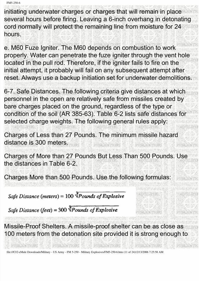
8/9/2019 Military - Us Army - Field Manual - Fm 5-250 - Military Explosives
http://slidepdf.com/reader/full/military-us-army-field-manual-fm-5-250-military-explosives 176/189
M5-250-6
nitiating underwater charges or charges that will remain in place
everal hours before firing. Leaving a 6-inch overhang in detonatin
ord normally will protect the remaining line from moisture for 24
ours.
. M60 Fuze Igniter. The M60 depends on combustion to workroperly. Water can penetrate the fuze igniter through the vent hol
ocated in the pull rod. Therefore, if the igniter fails to fire on the
nitial attempt, it probably will fail on any subsequent attempt after
eset. Always use a backup initiation set for underwater demolition
-7. Safe Distances. The following criteria give distances at which
ersonnel in the open are relatively safe from missiles created byare charges placed on the ground, regardless of the type or
ondition of the soil (AR 385-63). Table 6-2 lists safe distances for
elected charge weights. The following general rules apply:
harges of Less than 27 Pounds. The minimum missile hazard
istance is 300 meters.
harges of More than 27 Pounds But Less Than 500 Pounds. Use
he distances in Table 6-2.
harges More than 500 Pounds. Use the following formulas:
Missile-Proof Shelters. A missile-proof shelter can be as close as
00 meters from the detonation site provided it is strong enough to
le:///C|/2-eMule Downloads/Military - US Army - FM 5-250 - Military Explosives/FM5-250-6.htm (11 of 24)12/13/2006 7:25:58 AM
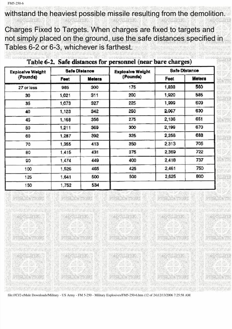
8/9/2019 Military - Us Army - Field Manual - Fm 5-250 - Military Explosives
http://slidepdf.com/reader/full/military-us-army-field-manual-fm-5-250-military-explosives 177/189
M5-250-6
withstand the heaviest possible missile resulting from the demolitio
harges Fixed to Targets. When charges are fixed to targets and
ot simply placed on the ground, use the safe distances specified
ables 6-2 or 6-3, whichever is farthest.
le:///C|/2-eMule Downloads/Military - US Army - FM 5-250 - Military Explosives/FM5-250-6.htm (12 of 24)12/13/2006 7:25:58 AM
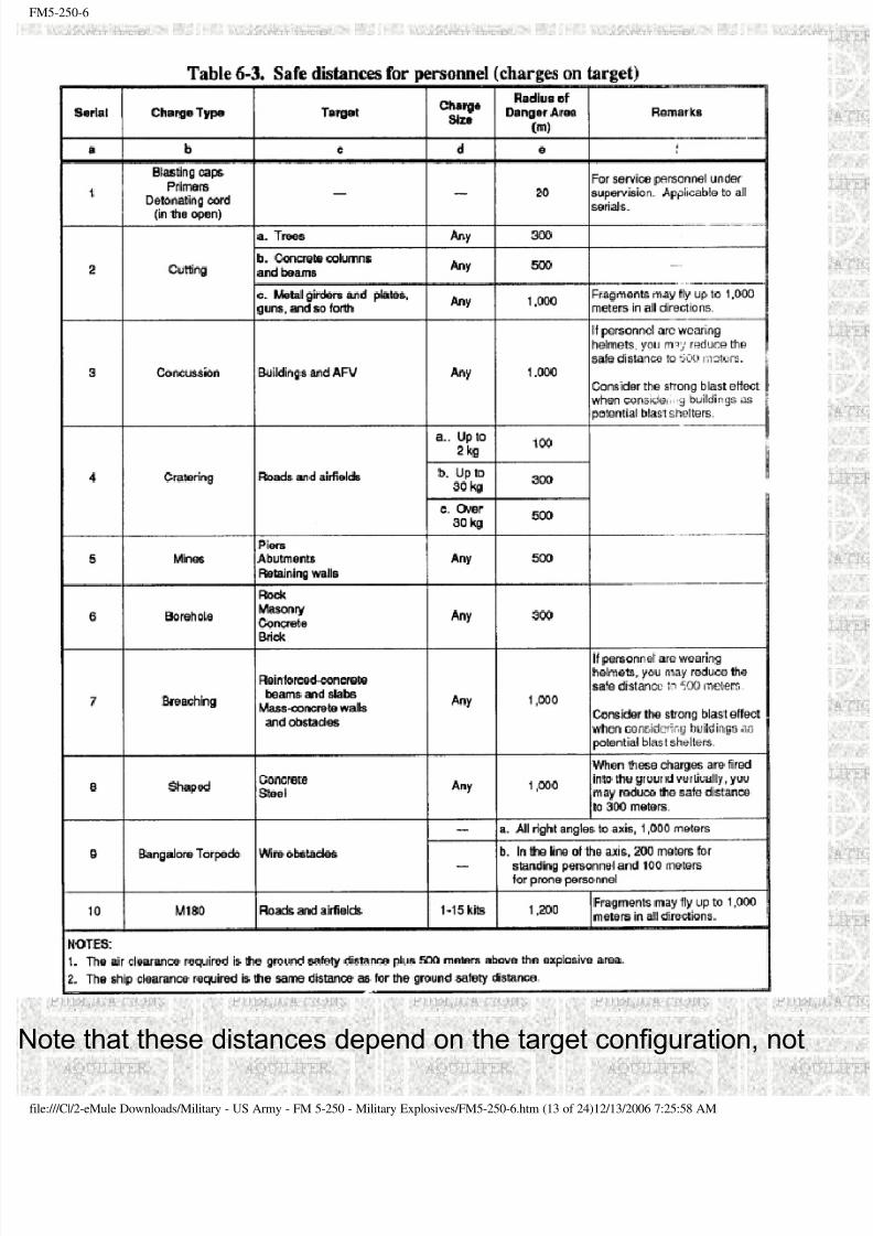
8/9/2019 Military - Us Army - Field Manual - Fm 5-250 - Military Explosives
http://slidepdf.com/reader/full/military-us-army-field-manual-fm-5-250-military-explosives 178/189
M5-250-6
ote that these distances depend on the target configuration, not
le:///C|/2-eMule Downloads/Military - US Army - FM 5-250 - Military Explosives/FM5-250-6.htm (13 of 24)12/13/2006 7:25:58 AM
8/9/2019 Military - Us Army - Field Manual - Fm 5-250 - Military Explosives
http://slidepdf.com/reader/full/military-us-army-field-manual-fm-5-250-military-explosives 179/189
M5-250-6
uantity of explosive.
ection II. Misfire Procedures
-8. Nonelectric Misfires.
. Causes.
Moisture in the time fuse, detonating cord, or explosives.
ime fuse not seated completely in blasting cap or in fuse igniter.
reaks in time fuse or detonating cord.
agged or uneven ends on time fuse.
lasting caps not seated securely in cap well or explosive.
oose or improper detonating-cord installation.
ebris in the blasting cap.
ommercial blasting caps were not strong enough to detonate
military explosives.
. Prevention. You can minimize nonelectric misfires by taking the
ollowing precautions:
repare and place all primers properly.
oad all charges carefully.
etonate charges with the proper techniques.
le:///C|/2-eMule Downloads/Military - US Army - FM 5-250 - Military Explosives/FM5-250-6.htm (14 of 24)12/13/2006 7:25:58 AM
8/9/2019 Military - Us Army - Field Manual - Fm 5-250 - Military Explosives
http://slidepdf.com/reader/full/military-us-army-field-manual-fm-5-250-military-explosives 180/189
M5-250-6
se dual-initiation systems and, if possible, dual firing systems.
se detonating cord for underground demolitions. Do not bury cap
erform tamping operations with care to avoid damaging prepared
harges.
void crimping blasting caps onto time fuse in the rain; seek a
overed area out of the rain.
nsure you completely seat time fuse when installing it into a
lasting cap or fuse igniter.
Clearing Procedure.
he soldier who placed the charges should investigate and correc
ny problems with the demolition.
fter attempting to fire the demolition, delay investigating any
etonation problem for at least 30 minutes plus the time remainingn the secondary. Tactical conditions may require investigation pr
o the 30-minute limit.
or above-ground misfires of charges primed with blasting caps,
lace a primed, l-pound charge next to the misfired charge and
etonate the new charge. Each misfired charge or charge separat
om the firing circuit that contains a blasting cap requires a 1-pounharge for detonation. Do not touch scattered charges that contain
lasting caps; destroy there in place. For charges primed with
etonating cord, use the procedures in paragraph 6-10 (page 6-10
or a nonelectric cap that has detonated but failed to initiate a
etonating-cord branch line, line main, or ring main, attach a new
le:///C|/2-eMule Downloads/Military - US Army - FM 5-250 - Military Explosives/FM5-250-6.htm (15 of 24)12/13/2006 7:25:58 AM
8/9/2019 Military - Us Army - Field Manual - Fm 5-250 - Military Explosives
http://slidepdf.com/reader/full/military-us-army-field-manual-fm-5-250-military-explosives 181/189
8/9/2019 Military - Us Army - Field Manual - Fm 5-250 - Military Explosives
http://slidepdf.com/reader/full/military-us-army-field-manual-fm-5-250-military-explosives 182/189
M5-250-6
lectrical wiring in a demolition circuit. This individual should do th
ollowing:
erform all splicing.
nstall all blasting caps in the firing circuit. Do not bury caps!
Make all of the connections between blasting cap wires, connectin
wires, and firing wires.
nspect system for short circuits.
void grounding out the system.
nsure the number of blasting caps in any circuit does not exceed
he rated capacity of the power source.
Clearing Procedure. Use the following procedures to clear elect
misfires:
Make another attempt to fire.
se the secondary firing system, when present.
heck the wire connections, blasting machine, or power-source
erminals.
isconnect the blasting machine or power source and test thelasting circuit. Check the continuity of the firing wire with a circuit
ester.
se another blasting machine or power source and attempt to fire
he demolition again, or change operators.
le:///C|/2-eMule Downloads/Military - US Army - FM 5-250 - Military Explosives/FM5-250-6.htm (17 of 24)12/13/2006 7:25:58 AM
8/9/2019 Military - Us Army - Field Manual - Fm 5-250 - Military Explosives
http://slidepdf.com/reader/full/military-us-army-field-manual-fm-5-250-military-explosives 183/189
M5-250-6
When employing only one electrical initiation system, disconnect t
lasting machine, shunt the wires, and investigate immediately.
When employing more than one electrical initiation system, wait 30
minutes before inspecting. Tactical conditions may require
nvestigation prior to the 30-minute limit.
nspect the entire circuit for wire breaks or short circuits.
you suspect an electric blasting cap is the problem, do not attem
o remove or handle it. Place a primed, 1-pound charge next to the
misfired charge and detonate the new charge.
-10. Detonating-Cord Misfires.
. Detonating Cord. If detonating cord fails to function properly, tak
he following action:
ttach a new blasting cap to the remaining detonating cord, taking
are to fasten it properly, and detonate the new blasting cap.
reat branch lines in the same manner as noted above.
. Detonating-Cord Priming. If the detonating cord leading to the
harge detonates but fails to explode the charge, take the followin
ction:
o not investigate until the charges have stopped burning. Wait 30minutes if the charge is underground.
Reprime and attempt to detonate the charge.
cattered charges that do not contain blasting caps may be
ollected and detonated together.
le:///C|/2-eMule Downloads/Military - US Army - FM 5-250 - Military Explosives/FM5-250-6.htm (18 of 24)12/13/2006 7:25:58 AM
8/9/2019 Military - Us Army - Field Manual - Fm 5-250 - Military Explosives
http://slidepdf.com/reader/full/military-us-army-field-manual-fm-5-250-military-explosives 184/189
M5-250-6
or underground charges, dig to within one foot of the charge; pla
primed, 2-pound charge on top or to the side of the charge; and
etonate the new charge.
ection III. Transportation and Storage Safety
-11. Transportation.
. Regulations. Both military and commercial carriers are subject t
egulations when transporting military explosives and other
angerous military materials within the United States.
R 55-355 covers the transportation of explosives. When
ansporting explosives outside the United States, follow the
egulations from the host countries as well. TM 9-1300-206 contain
minimum safety requirements for handling and transporting militar
xplosives and ammunition.
ll explosives transport personnel must learn the local proceduresnd safety requirements.
. Safety Procedures. The commander should assign a primary an
ssistant operator to each vehicle transporting explosives on publi
ighways, roads, or streets. Whenever transporting explosives
ocally, operators must observe the following safety rules:
1) Vehicles.
nsure vehicles are in good condition. Inspect all vehicles intende
or hauling explosives before loading any explosives. Pay particula
ttention to protecting against any short circuits in the electrical
ystem.
le:///C|/2-eMule Downloads/Military - US Army - FM 5-250 - Military Explosives/FM5-250-6.htm (19 of 24)12/13/2006 7:25:58 AM
8/9/2019 Military - Us Army - Field Manual - Fm 5-250 - Military Explosives
http://slidepdf.com/reader/full/military-us-army-field-manual-fm-5-250-military-explosives 185/189
M5-250-6
When using vehicles with steel or partial-steel bodies, install fire-
esistant and nonsparking cushioning to separate the explosives
om the metal truck components.
o not load vehicles beyond their rated capacities whenansporting explosives.
over open-body vehicles hauling explosives with a fire-resistant
arpaulin.
Mark all vehicles transporting explosives with reflective placards
ndicating the type of explosives carried (TM 9-1300-206, Chapter
se demolition transports for explosives only. Do not carry metal
ools, carbides, oils, matches, firearms, electric storage batteries,
ammable substances, acids, or oxidizing or corrosive compounds
n the bed or body of any vehicle transporting explosives.
quip vehicles transporting explosives with not less than two Clas-BC fire extinguishers for on-post shipments. Place the
xtinguishers at strategic points, ready for immediate use.
eep vehicles away from congested areas. Consider congestion
when parking.
Operate vehicles transporting explosives with extreme cam. Do norive at a speed greater than 35 miles per hour. Make full stops at
pproaches to all railroad crossings and main highways. This does
ot apply to convoys or crossings protected by guards or highway
workers (flaggers).
eep flames at least 50 feet from vehicles or storage points
le:///C|/2-eMule Downloads/Military - US Army - FM 5-250 - Military Explosives/FM5-250-6.htm (20 of 24)12/13/2006 7:25:58 AM
8/9/2019 Military - Us Army - Field Manual - Fm 5-250 - Military Explosives
http://slidepdf.com/reader/full/military-us-army-field-manual-fm-5-250-military-explosives 186/189
M5-250-6
ontaining explosives.
2) Cargo (Explosives).
ever leave explosives unattended.
ever mix live and inert (dummy) explosives.
ecure the load of explosives in the transport to prevent shifting
uring transport.
ransport blasting caps separately from other explosives. Do not
ansport blasting caps or other initiators in the same vehicles
arrying explosives. If both blasting caps and explosives must be
arried in the same vehicle, separate blasting caps from the other
xplosives by carrying the caps in a closed metal container in the
ab of the transport.
o persons other than the primary and the assistant operators will
de on or in a truck transporting explosives. Do not refuel a vehiclwhile carrying explosives except in an emergency.
3) Fire. If fire breaks out in a vehicle transporting explosives, take
he following actions:
ry to stop the vehicle away from any populated areas.
top traffic from both directions. Warn vehicle drivers and
assengers and occupants of nearby buildings to keep at least
,000 feet away from the fire. Inform police, fire fighters, and other
mergency-response personnel that the cargo is explosives.
the fire involves only the engine, cab, chassis, or tires, make an
le:///C|/2-eMule Downloads/Military - US Army - FM 5-250 - Military Explosives/FM5-250-6.htm (21 of 24)12/13/2006 7:25:58 AM
8/9/2019 Military - Us Army - Field Manual - Fm 5-250 - Military Explosives
http://slidepdf.com/reader/full/military-us-army-field-manual-fm-5-250-military-explosives 187/189
M5-250-6
ffort to extinguish the fire with fire extinguishers, sand, dirt, or
water. If the fire spreads to the body of the transport or the cargo,
top fighting the fire and evacuate to a distance of at least 2,000
eet.
o not attempt to extinguish burning explosives without expertdvice and assistance.
-12. Storage Safety.
. Magazines. There are two types of magazines: permanent and
emporary. Although permanent magazines are preferred,
emporary or emergency magazines are frequently required whenermanent construction is not possible. Field Manual (FM) 9-6 and
M 9-1300-206 give details on magazine storage of explosives.
onsider the following when constructing magazines:
1) Permanent.
a) Placement. Consider acceptability of magazine locations basedn safety requirements, accessibility, dryness, and drainage. Safe
nd accessibility are the most important. An ideal location is a hilly
rea where the height of the ground above the magazine provides
atural wall or barrier to buildings, centers of communication, and
ther magazines in the area. Hillside bunkers are not desirable
ecause adequate ventilation and drainage are often difficult to
chieve. Clear brush and tall grass from the site to lessen the
anger of fire.
b) Lightning protection. All magazines must have a grounded,
verhead lightning-rod system.
le:///C|/2-eMule Downloads/Military - US Army - FM 5-250 - Military Explosives/FM5-250-6.htm (22 of 24)12/13/2006 7:25:58 AM
8/9/2019 Military - Us Army - Field Manual - Fm 5-250 - Military Explosives
http://slidepdf.com/reader/full/military-us-army-field-manual-fm-5-250-military-explosives 188/189
M5-250-6
onnect all metal parts (doors, ventilator, window sashes,
einforcing steel, and so forth) to buried conduits of copperplate or
raphite rods in several places.
c) Barricades. Install barricades around magazines; that is, there
must be a substantial obstacle between magazines and inhabiteduildings. For certain explosives, effective natural or artificial
arricades reduce the required safe distance between magazines
nd railways and highways by one half. The use of barricades
ermits the storage of larger quantities of explosives in any given
rea.
lthough barricades help protect magazines against explosives anomb or shell fragments, they do not safeguard against pressure
amage. TM 9-1300-206 gives more specific guidance on
arricades.
d) Security. Place guards at all magazines to prevent unauthorize
ersonnel from gaining access to magazine facilities.
2) Temporary.
a) Placement. When permanent magazine construction is not
ossible, create temporary magazines by placing explosives on
allets to accommodate ventilation. Store the pallets in a well-
rained bunker. Excavate the bunker in a dry area and revet the
unker with timber to prevent collapse. Alternatives are an isolated
uilding or a light, wooden-frame house with a wedge-type roof
overed with corrugated iron or tent canvas.
b) Identification. Mark field-expedient storage facilities on all four
des with signs (TM 9-1300-206).
le:///C|/2-eMule Downloads/Military - US Army - FM 5-250 - Military Explosives/FM5-250-6.htm (23 of 24)12/13/2006 7:25:58 AM
8/9/2019 Military - Us Army - Field Manual - Fm 5-250 - Military Explosives
http://slidepdf.com/reader/full/military-us-army-field-manual-fm-5-250-military-explosives 189/189
M5-250-6
. Temporary Storage. When necessary, store limited supplies of
xplosives in covered ammunition shelters. Ensure the temporary
acilities are separated adequately to prevent fire or explosion from
eing transmitted between shelters. Piles of temporarily stored
xplosives should contain no more than 500 pounds each and be
paced no closer than 140 feet. Pile explosive components
eparately. Keep explosives, caps, and other demolition materials
tored in training areas in covered ammunition shelters and under
uard at all times. Local safety standing operating procedures
SOPS) and TM 9-1300-206, Chapter 4, are guides for temporary
torage operations.