MILITARY SPECIFICATION RIFLE, 7.62MM, SNIPER
53
MIL-R-71126(AR) 24 September 1992 . o MILITARY SPECIFICATION RIFLE, 7.62MM, SNIPER W/ DAY OPTICAL SIGHT AND CARRYING CASES, M24 ‘This specification is approved for use by the U.S. Army Armament, Munitions and Chemical Command, and is available for use by all Departments and Agencies of the Department of Defense. 1. SCOPE 1.1 Scope. This specification covers the performance, characteristics, firing, packaging and quality assurance requirements for the Rifle, 7.62mm, Sniper with day optical sight, and carrying cases, M24. The M24 is comprised of a rifle, a detachable day optical sight with a carrying case, iron sights and a carrying case for all the components. 2. APPLICABLE DOCUMENTS 2.1 Government documents. 2.1.1 Specifications, standards and handbooks. The following specifications, standards and handbooks form a part of this document to the extent specified herein. Unless otherwise specified, the issues of these documents shall be those listed in the issue of the Department of Defense Index of Specifications and Standards (DoDISS) and supplement thereto, cited in the solicitation (6.2). SPECIFICATIONS MILITARY MIL-B-117 -Bag, Sleeve and Tubing - Interior Packaging FIIL-G-174 -Glass, Optical MIL-C-372 -Cleaning Compound, Solvent MIL-C-675 -Coating of Glass Optical Elements (Anti- reflection) r Beneficial comments (recommendations,additions, deletions) and any pertinent ciata which may be of use in improving this document, should be addressed to: Commander U.S. Amy ARDEC, ATTN: SMCAR-BAC-S, Picatlnny Arsenal, New Jersey 07806-5000 by using the self-addressed StandardizationDocument Improvement Proposal o 4 (DD Form 1426] appearing at the end of this document or by letter. + ANISCWA Fsc 1005 ~T &ApPmwctror public mkase;distribution isunlimited. Downloaded from http://www.everyspec.com
Transcript of MILITARY SPECIFICATION RIFLE, 7.62MM, SNIPER
MIL-R-71126(AR)24 September 1992
.
o
MILITARY SPECIFICATION
RIFLE, 7.62MM, SNIPERW/ DAY OPTICAL SIGHT AND
CARRYING CASES, M24
‘This specification is approved for use by the U.S. ArmyArmament, Munitions and Chemical Command, and is availablefor use by all Departments and Agencies of the Department ofDefense.
1. SCOPE
1.1 Scope. This specification covers the performance,characteristics, firing, packaging and quality assurancerequirements for the Rifle, 7.62mm, Sniper with day optical sight,and carrying cases, M24. The M24 is comprised of a rifle, adetachable day optical sight with a carrying case, iron sights anda carrying case for all the components.
2. APPLICABLE DOCUMENTS
2.1 Government documents.
2.1.1 Specifications, standards and handbooks. Thefollowing specifications, standards and handbooks form a part ofthis document to the extent specified herein. Unlessotherwise specified, the issues of these documents shall be thoselisted in the issue of the Department of Defense Index ofSpecifications and Standards (DoDISS) and supplement thereto,cited in the solicitation (6.2).
SPECIFICATIONS
MILITARY
MIL-B-117 -Bag, Sleeve and Tubing - Interior PackagingFIIL-G-174 -Glass, OpticalMIL-C-372 -Cleaning Compound, SolventMIL-C-675 -Coating of Glass Optical Elements (Anti-
reflection)rBeneficial comments (recommendations,additions, deletions) and any pertinent ciatawhich may be of use in improving this document, should be addressed to: CommanderU.S. Amy ARDEC, ATTN: SMCAR-BAC-S, Picatlnny Arsenal, New Jersey 07806-5000by using the self-addressed StandardizationDocument Improvement Proposal
o 4(DD Form 1426] appearing at the end of this document or by letter.
+
ANISCWA Fsc 1005~T &ApPmwctrorpublicmkase;distributionisunlimited.
Downloaded from http://www.everyspec.com
M1L-R-71126(AR)
MIL-A-8625
MIL-O-13830
MIL-W-13855
MIL-F-13926
MIL-L-14107MIL-L-46000MIL-C-46477
MIL-C-46934MIL-L-63460
MIL-W-63150
STANDARDS
FEDERAL
FED-STD-101
MILITARY
MIL-STD-109MIL-STD-129MIL–STD-130
MIL-STD-171MIL-STD-81O
–Anodic Coatings, for Aluminum and AluminumA:lloys
-Optical Components for Fire ControlInstruments . General SpecificationGoverning the Manufacture, Assembly andInspection of
–Weapons: Small Arms and AircraftA:rmament Subsystems, GeneralSpecification for
–Fire Control Material, Manufacture andInspection General Specification for
–Lubricating Oil, Weapons, Low Temperature–Lubricant, Semi–Fluid (Automatic weapons)–Cartridge, 7.62mm, NATO, Test, HighPressure, M60
–Cartridge, 7.62mm, NATO, special Ball, M118
–Lubricant, Cleaner and Preservative forWeapons and Weapons Systems-Weapons and Support Materiel StandardQuality Assurance Provisions for
-Test procedures for Packaging Materials
–Quality Assurance Terms and Definitions-Marking for Shipment and Storage–Identification Marking of US MilitaryProperty
–Finishing of Metal and Wood Surface-Environmental Test Methods
MIL–STD–1472 –Human Engineering Design Criteria forMilitary Systems, Equipment and
f FacilitiesMIL–STD–1474 –Noise Limits for Army MaterielMIL–STD–1949 –Inspection process, Magnetic particle
HANDBOOKS
MIL–HDBK-759 –Human Factors Engineering
(Unless otherwise indicated, copies of federal and militaryspecifications, standards, and handbooks are available from theStandardization Documents Order Desk, Bldg. 4D, 700 RobbinsAvenue, Philadelphia, PA 19111-5094).
2
Downloaded from http://www.everyspec.com
MIL-R-71126(AR)
2.1.2 Other Government documents, drawings, and publications .The following other Government documents, drawinqs, andpublications form a part of this document to the-extentspecified herein. Unless otherwise specified, the issues arethose cited in the solicitation.
DRAWINGS (See 6.6)
U.S. ARMY ARMAMENT, RESEARCH, DEVELOPMENT AND ENGINEERINGCENTER (ARDEC)
PRODUCT AND PACKING DRAWINGS
7141245 -Slinq, Leather, M19075564174 -Brusi; Cleaning, Cal .30
NATICK LAB DRAWING
D2-2-282 Cleaning Pouch
PUBLICATIONS
DEPARTMENT OF DEFENSE
TOP-3-2-609 -Chemical Comparability of Non-MetallicMaterials
(Copies of other Government documents, standards, drawings, andpublications required by contractors in connection with specificprocurement functions should be obtained from the contractingactivity or as directed by the contracting officer. )
2.2 Non-g overnment publications. The following documentsform a part of this document to the extent specified herein.Unless otherwise specified, the issues of the documents which areDoD adopted are those listed in the issue of the DoDISScitied in the solicitation. Unless otherwise specified, theissues of documents not listed in the DoDISS are the issues ofthe documents cited in the solicitation (see 6.2).
AMERICAN METALS sOCIETY (AMs)
AP4S 2469 -Aluminum & Aluminum Alloys, Processing &Requirements, Hard Coating Treatment of
(Application for copies should be addressed to the societyof automotive Engineers, 40 Commonwealth Drive, Warrendale, PA,15096) .
Downloaded from http://www.everyspec.com
AMERICAN NATIONAL
ANSI-B46
(Application for
MIL-R-71126(AR)
STANDARDS INSTITUTE
–Surface Texture (Surface Roughness~Waviness and Lay)
copies should be addressed to the AmericanNational Standards Institute, 1430, Broadway, New York, Ny 10018-3308)
AMERICAN SOCIETY FOF[ TESTING AND MATERIALS (ASTM)
ASTM–B117 -Standard Method of Salt Spray (Fog)Testing
ASTM-D3951 –E)ackaging, Commercial
(Application for copies should be addressed to the AmericanSociety for Testing and Materials, 1916 Race Street, Philadelphia,PA 19103-1187. )
2.3 Order of precedence. In the event of a conflict betweenthe text of this document and the references cited herein,the text of this specification takes precedence. Nothing in thisdocument, however, supersedes applicable laws and regulationsunless a specific exemption has been obtained.
3. REQUIREMENTS c
3.1 First Article. When specified (see 6.2), a sample shallbe subjected to first article inspection in accordance with 4.4.
3.2 Materials and construction. The M24 shall conform tothe materials and construction requirements specified herein and bein accordance with the applicable materials and constructionprovisions of MIL-W-1385!5 and MIL-F-13926. Parts and surfacessubjected to rolling or sliding contact shall be of sufficienthardness to resist wear. Staked or dovetailed members shall havesufficient temper to retain their original fit after extended use.Screws, when firmly tightened, shall not cause binding of any ofthe mechanisms. External pins shall be secured in position bydetent or retainer.
3.3 Design. Unless otherwise specified in the contract, theM24 shall conform to the human factors provisions of MIL–STD–1472 and MIL-HDBK-759.
3.3.1 Component carrying case. The component carrying caseshall have provisions to securely contain and protect thefollowing: rifle without day optical sight mounted on the rifle;the unmounted day optical sight enclosed in its carrying case; the
Downloaded from http://www.everyspec.com
,. ,
e MIL-R-71126(AR)
rifle cleaning kit; two (2) magazines if the magazines aredetachable from the rifle, and the deployment kit. If the ironsights are detachable, they shall be enclosed in the day opticalsight carrying case.
3.4 Machine finish. Machine finishes shall be in accordancewith commercial Practice for the rifle, iron sights and opticalsight furnished.- First article rifles, and the-aforementionedsighting systems (see 3.1) shall be used as standards for machinefinishes for production items. In the event of a dispute overthe comparison of finishes of the inspection standards and theproduction items, referee comparison shall be in accordance
● with ANSI B46.1.
3.5 Final protective finish. Unless otherwise specified. (see 6.2) the final finish of the exterior of metal parts shall be
in accordance with the applicable finishes listed below.The final protective finishes shall not apply to springs, orspring pins which may be left bright. However, exterior exposedsurfaces of these parts are subject to the touchup requirements inaccordance with 3.6. A commercial protective finish may be usedin lieu of those specified in this paragraph provided that finishmeets the corrosion resistance requirements of 3.12 and 4.6.3. Aprotective finish shall not be applied to the firing pin. A~~
o
carbon steel parts in the deployment kit shall be coated withlubricant per MIL-L-63460 (CLP).
Material Finish
Steel (other than corrosionresisting steel) 5.3.1.2 or 5.3.2.2 **
of MIL-STD-171Corrosion-resisting steel 3.3.2 or 3.3.3 of
MIL-STD-171Aluminum and aluminum alloys 7.1.2 or 7.2.2 (dyed black)
or 7.5* of JwIIL-STD-171 orMIL-A-8625, Type 11 or 111,class 1 or 2, color offinished parts shall belusterless uniform dark greyor black.
* The following provisions shall apply to finish number 7.5:
a. Thickness of coating shall be 0.002 + 0.0002 inch.
5
Downloaded from http://www.everyspec.com
MIL–R–71126(AR)
b. In lieu of the abrasion and wear resistance testspecified in AMS 2469, resistance to wear may be determined byother suitable means as approved by the procuring activity.
** Finish number 5.3.2.2 shall not be used on steel parts thatare subjected to rolling or sliding contact.
3.6 Touchup material. Exterior surfaces on metal componentswhich are briqht or with~t finish after assemblv o~erations, such. .as the surfaces of rivets, pins, screw heads, staking marks andthe like shall be refinished using materials and procedures inaccordance with the touchup procedures of MIL–W–13855.
3.7 Human engineering characteristics. In addition tomeeting the design requirements specified herein, rifles, sightingsystems and carrying cases shall meet with approval of theGovernment for human engineering characteristics in accordancewith MIL–STD–1472 (para 5.4 and 5.11).
3.8 Operator’s manual. An operator’s manual which clearlyand fully explains the operations, field stripping and maintenanceshall be provided with each M24. This manual shall also include aparts list keyed to an exploded assembly drawing. The manualshall be placed in a plastic bag conforming to Type I, Class B,Style 2 of MIL-B-117, for packing.
o3.9 Parts list. The contractor shall provide a
—
comprehensive parts list with the quantities required to maintainthe M24 over a period of 10,000 rounds of firing. The. list shouldreflect but need not specifically identify all data available tothe contractor, such as a factory replacement and repair history,contractor test and endurance test history,sales to dealer andrepair stations, etc.
3.10 NBC decontamination. The M24, except for the interiorof the carrying cases, s!~all be NBC decontamination survivable.
3.11 Fungus. The lfi24shall be fungus resistant.
3.12 Corrosion resistance. All components of the M24 shallbe corrosion resistant. All metal components shall meet thecorrosion resistance requirement of paragraph 5.1.3.1, 5.1.3.2,5.1.3.3 and 5.1.3.4 of MIL-STD-171 as applicable.
3.13 Chemical resistance. All components of the M24, exceptfor the interior of the carrying cases, and except for theadjustment knobs, lenses, and lens cover on the day optical sight,shall not be affected by petroleum, oil and lubricant products,insect repellents and other common battlefield compounds, listed
Downloaded from http://www.everyspec.com
I
M.L-R-71126(AR)
in TOP 3-2-609. The interior of the component carrying case shallnot be affected by LSA (MIL-L-46000), CLP (MIL-L-63460), LAW (MIL-L-14107) and RBC (MIL-C-372).
3.14 Rifle.
3.14.1 Weight/size. The rifle shall weigh no more than 16pounds when mounted with the day optical sight and equipped withsling swivels, carrying strap and with the magazine fully loadedwith ammunition. The total length of the rifle shall not be morethan 46 inches with the stock adjusted to the minimum length.
3.14.2 Cleaning equipment. The rifle shall be supplied with “a cleaning rod and cleaning patch eyelet which shall not causescratches, burrs nor any other type of damage or wear detrimentalto the rifle, rifle barrel or any other parts. The cleaning rodshall be compatible with cleaning brush Dwg. 5564174. Thecleaning rod shall fit into the cleaning pouch (Dwg. D2-2-282)(NATICK Lab Dwg.) and shall be capable of being used with standardDOD lubricants and solvents.
3.14.3 Maintainability. The rifle shall be designed toallow the operator to perform necessary maintenance using standardDOD lubricant/solvent, without the use of any tools other thanthe equipment in the cleaning kit and deployment kit. Thedeployment kit shall consist of replacement parts including atleast one (1) firing pin and any tools required for maintenance ofall operator level functions on the SWS. It shall be designedsuch that as a minimum the operator can replace the firing pin.
3.14.4 Magazine. The magazine shall have a minimum capacityof four rounds. The magazine shall not protrude below the toe ofthe stock and shall be free of defects which may affect thefunctioning of either the magazine or the rifle.
3.14.5 Noise. The rifle, when firing MI18 ammunition, shallnot exceed curve Y of the peak pressure level and B-durationlimits for impulse noise of MIL-STD-1474.
3.14.6 Sling swivels. The rifle shall have detachable(without the use of tools) sling swivels which will accommodate a1 1/4 inch wide carrying strap (sling, leather, M1907) (Dwg.7141245). The front sling swivel shall have a minimum openingheight of 3/8 inch.
3.14.7 Exterior surface. All components of the rifle shallhave permanent nonreflective exterior surfaces. The color shallbe black or camouflage green.
7
Downloaded from http://www.everyspec.com
MIL-R-71126(AR)
3.14.8 Stock. The stock shall have an adjustable length ofpull . Adjustments shall be continuous or incremental, with amaximum of 1/4 inch increments, over a minimum acceptable lengthof pull range of 12 to 14 inches. Adjustment of the stock, atambient temperature, shall be accomplished within 3 minuteswithout the use of special tools. Special tools are tools notcontained in the cleaning or deployment kit. The stock shall beadjustable at ambient, hot (1450 + 5oF) and cold (-50° + 5° F).The stock shall be adjustable by ; person dressed in cold weatherenvironmental clothing (with the exception of the outer articmitten) and NBC clothing.
3.14.8.1 Stock surface. The gripping surfaces of theforestock and stock shall have non–skid surface textures inaccordance with MIL–STD-1472 (para 5.9.11.5.4).
3.14.9 Bolt assemb~. The bolt assembly shall beremovable and replaceable within one minute without the use ofany tools.
3.14.10 Soundness of weld. All welds shall show goodfusion. The weld and welded parts shall be free of cracks,porosity, inclusions and other metallic discontinuities.
3.14.11 Safety. T’he rifle shall have a safety device whichshall be detented in both the extreme “safe” and extreme “fire” ●position and, when in the safe position, will prevent the weaponfrom firing. The shooter shall be able to verify the position ofthe safety by both sight and touch. It shall be movable betweenthe safe and fire positions by the operator without moving hishands from the shooting position (prone, standing, kneeling,sitting) . It shall remain in the position the operator sets ituntil it is manually changed. The safety shall provide tactilefeedback during movement from one position to another. The safetyshall require a force of between 2 to 10 pounds to operate.
The safety shall perform all the above operations at ambient,hot (1450 + 50F) and cold (–500 + 5oF) and by a person dressedin cold we=ther environmental cl~thing (except for the outer articmitten) and NBC clothing.
3.14.12 Iron sights. The rifle shall have accurate, matchgrade quality iron sight= capable of engaging “E” silhouettetargets at ranges up to and including 600 meters.
The iron sights, if detachable, shall be capable of beingdetached and reattached by the operator with no tools other thanthose contained in the deployment kit and when reattached shallrepeat zero to within 1 minute of angle (MOA) .
Downloaded from http://www.everyspec.com
.
●
I
I
i
MIL-R-71126(AR)
The configuration of the iron sights shall consist of a frontsight and a rear peep sight. The rear peep sight shall have amovable scale for zeroing purposes.
The iron sights may have inserts for the front sight and therear peep sight. If the iron sights have inserts, they shall bereplaceable by the operator with no tools other than thosecontained in the deployment kit.
The width of the front sight shall be such that it is thenar~owest one offered by the contractor.
The iron sights shall be adjustable for both elevation andazimuth in increments no greater than .S MOA increments. Theadjustments shall be detented, audible and tactile clicks and becapable of being performed at ambient, hot (1450F + 5oF) . cold(-50° F ~ 5° F) by a person dressed in cold weather ~nvironmental
-——
clothing (less the outer arctic mitten) , and by a person dressedin NBC clothing.
3.15 Performance Characteristics.
3.15.1 Headspace. The headspa,ce shall be a maximum of 1.640inches and a minimum of 1.630 inches. Variance from these valuesshall require Government approval.
—
3.15.2 Trigger pull . The rifle shall have a trigger pullcapable of being adjusted in force and in movement after releaseby the operator. The minimum force shall be 2 pounds 8 ounces + 8ounces. The maximum force shall be at least four pounds. Afte~adjustment of the trigger pull, the rifle shall demonstrate theability to consistently retain the trigger pull setting within + 8ounces at 2.5 pounds, within + 12 ounces at 3.0 pounds and with~n+ 16 ounces at 4 pounds, but In no case shall it go below 2Founds. The trigger shall return to its normal forward positionimmediately upon release after partial or complete trigger pull.
3.15.3 Functioning. The rifle shall operate withoutmalfunctions or unserviceable parts. After functioning, the dayoptical sight shall meet the cleanliness and optical qualityrequirement (3.16.10). Unless otherwise s~ecified, all ammunitionused shall be GovernmentCartridges in accordance
3.15-4 Endurance.withstand a 10,000 roundcapable of firing 10,000
standard 7.62mm N~TO, Special Ball, M118--with MIL-C-46934.
The rifle and day optical sight shallendurance test. The rifle shall berounds without the receiver requirinq
overhaul. The r~ceiver shall be free of cracks. Crack; shali bedefined as cracks that are detected by magnetic particleinspection with the unaided eye.
9
Downloaded from http://www.everyspec.com
MIL-R-71126(AR)
The rifle shall have a barrel which is accurate and is freeof cracks for a minimum o:E 5000 rounds. The barrel shall beconsidered worn out when the average mean radius, calculated usingfive tarqets of ten shots each, exceeds the values listed belowfor the ;angesmachine rest.
200 yards300 yards
specified when fired from a Government approved
Average Mean Radius (AMR)
2.6 inches3.8 inches
200 meters 2.8 inches
The rifle and day optical sight shall meet the reliabilityrequirements of 3.15.5.
3.15.5 Reliability. The mean round between stoppage (MRBS)for the rifle shall be 1400 rounds. The MRBS is the total numberof rounds fired divided b:y the total number of stoppages. Astoppage shall be defined as any malfunction* of the rifle.
* A malfunction is defined as any incident resulting in systemstoppage (unplanned cessation in firing or inability tocommence firing) . A malfunction also includes systemstoppages which are traceable or chargeable to anunserviceable part. Malfunction descriptions includesystem stoppages which are traceable or chargeable to anunserviceable part. Malfunction descriptions includefailures to feed, extract, eject, close, fire, or failure tofunction of the magazine. When it is definitely establishedby the Government representative that previously recordedmalfunctions are attributable to an unserviceable part, suchmalfunctions shall not be counted against the rifle beingtested, provided they occurred not more than 200 rounds priorto replacement of the unserviceable part. These 200 roundsshall have been fired with the unserviceable part. However,such malfunctions shall remain recorded and properlyidentified. Malfunctions attributed to ammunition, assubstantiated by a contractor failure analysis acceptable tothe Government representative, shall not be counted againstthe rifle\magazine being tested. However, they shall berecorded and properly identified with supporting analysis.
The mean round between failure (MRBF) for the rifle and dayoptical sight shall be 2600 rounds, the MRBF is the total numberof rounds fired divided by the total number of failures. Afailure shall be one or more of the following:
1. Any stoppage that cannot be corrected within 10 seconds.
10
Downloaded from http://www.everyspec.com
1
II
t
t
I
I
MIL-R-71126(AR)
2. Any parts that are replaced. Each part that is replacedshall be counted as one failure, except where the parts failuresare interrelated. In this case, all the parts failures that a-reinterrelated, shall be counted as one failure. Replacement of thebarrel after 5000 rounds shall not be counted as a failure.
3. Occurrence of a crack in the bolt.
4. The day optical sight becomes loose or falls off within500 rounds of being fixed to the rifle.
5. The maximum change between the point of aim and the centerof impact exceeds 1.086 minutes of angle.
3.15.6 High- -pressure resistance. The rifle shall withstandthe proof firing of one Government standard 7.62mm, M60 high--pressure test cartridge. Cartridges shall be in accordance withMIL-C-46477. Parts shall be free of cracks after proof firing asevidenced by visual and magnetic particle inspection. As aminimum, the barrel, bolt and receiver shall be inspected bymagnetic particle.
3.15.7 Targeting and accuracy. The rifle shall achieve thedispersion set forth below when fired from a Government approvedmachine rest. The average mean radius shall be less than or equalto the values stated below. The minimum rate of fire forconducting this test shall be three rounds per minute.
Range Average Mean Radius (AMR)
200 yards 1.3 inches300 yards 1.9 inches
200 meters 1.4 inches
The radial distance from the calculated center of impact ofthe first target compared to the calculated center of impacts ofthe subsequent targets shall be less than or equal to 1.086minutes of angle (3.3 inches (?300 yards, 2.2 inches @ 200 yards,2.4 inches @ 200 meters] on an average basis. After the rifle iszeroed on the target, there shall be a minimum of 30 tactileclicks (15 minutes of angle) of windage adjustment (in both theleft and right directions) and a minimum of 40 tactile clicks (40minutes of angle for system superelevation adjustment) ofelevation adjustment between the zeroed position of the reticleand the extreme adjustment position.
11
Downloaded from http://www.everyspec.com
MIL-R-71126(AR)
3.15.8 Drop test - rifle. The rifle, with the safety inthe safe position and an empty primed M118 cartridge in thechamber, shall withstand a five foot drop onto dirt. The dirtshall have a minimum soil. penetration resistance of 750 pounds persquare inch at a depth between one and one and one half inches.The primed cartridge shall not discharge. There shall be nofunctional damage to the rifle. After rezeroing, the rifle shallmeet the targeting and accuracy requirement (3.15.7) .
3.15.9 Firing pin indent. The minimum firing pin indent atambient temperature shall. be 0.020 inches when tested as specifiedin 4.6.19.
3.15.10 Temperature extremes. The rifle with day opticalsight shall be operable and safelY functionable at hot (145° 350F) and cold (-500 + 5oF) and shall be operable by the shooterdressed in cold weatfier environmental clothing (except for theouter artic mitten) at the cold temperature.
3.15.10.1 Cold temperature functioning. The rifle shall becapable of firing 300 rounds at cold temperature (–50° ~ 5° F) withthe occurrence of a total of no more than 18 stoppages and partsfailures.
3.15.11 Special clothing. The rifle with day optical sightshall be operable by the shooter when dressed in NBC clothing. ●
3.15.12 Interchangeability. All operator level repairparts that are field serviceable shall be interchangeable.
3.16 Day optical sight.
3.16.1 Magnification. The magnification shall be 10 or 12power.
3.16.2 Elevation and windage adjustment. Adjustment forelevation and windage shall be knobs which have clearly markedgraduations and tactile clicks. The zero position of the reticleshall not move more than .55 MOA from the optical axis when eachknob is cycled from O to the extreme adjustments and returned, for10 cycles. The elevation and windage adustment shall meet theabove requirements at ambient temperature.
3.16.3 Lens cover. The lens covers shall provide protectionto the lenses from sunlight, debris and dust. The lens coversshall be capable of being securely fastened to the day opticalsight, and shall be flip up with a detent lock.
12
Downloaded from http://www.everyspec.com
I
.—Le MIL-R-71126(AR)
3.16.4 Reticle. The day optical sight shall have a scaled,cross hair reticle with one mil increment dots that will assistthe shooter in compensating for wind, target movement, andestimation of range.
3.16.5 Anti-reflection coating. All lens surfaces shall becoated with an anti-reflection coating that conforms to minimumdurability requirements in 3.8.4.2 and 3.8.5 of MIL-C-675. Thecoating shall allow at least 85% light transmission for theassembled sight unit.
3.16.6 Optical glass. The optical glass shall meet therequirements of grade C of specification MIL-G-174.
3.16.7 Parallax. The focus parallax between center of the. reticle and image of a target out to a range of 800 meters shall
not exceed 0.5 minutes of angle.
3.16.8 Eyepiece focus. The eyepiece shall be easilyadjustable and provide at least plus 2 diopters to minus 4diopters from the position of best focus on the reticle surface.
3.16.9 Resolution. At the center of field of view, thesight unit shall resolve 9 seconds of angle or better.
e 3.16.10 Cleanliness and optical quality. There shall be noevidence of glass, fracture, cement separation, grease orfingerprints on any optical component when viewing through theobjective or eyepiece end of the sight unit. There shall not bemore than 3 particles of foreign matter visible on the reticlesurface and no particle shall exceed the apparent width of areticle line. There shall be no foreign matter obvious to theunaided eye which would impair optical performance when lookinginto the eyepiece against a background having a brightness of thesky in average daylight.
3.16.11 Watertightness. The day optical sight shall show noevidence of leakage when subjected to a minimum pressure of 32.5pounds per square inch atmospheric by being submerged in water fora 5 minute period. No moisture or fogging shall be observed.
3.16.12 Sealing. All internal optical areas of the dayoptical sight shall be purged with dry nitrogen. The sight unitshall be sealed such that the interior is moisture-free afterpurging. The sight unit shall remain sealed after being exposedto an external pressure of 4.4 pounds per square inch atmosphericfor a minimum of 8 hours.
3.16.13 Exterior surface. All components of the day opticalsiqht except the lenses, shall have a permanent non-reflective
*
ex~erior s;rface. The lens surfaces shall comply with 3.16.5.
13
Downloaded from http://www.everyspec.com
MIL-R-71126(AR)
3.16.14 Reattachment. The day optical sight shall becapable of being removed>nd replaced on the rifle using only thetools contained in the deployment and cleaning kits. The dayoptical sight shall be capable of being removed from the rifleand reattached for a minimum of 180 cycles. The maximum change inthe zero of the weapon shall be 1/2 minute of angle.
3.16.15 Drop test day optical “sight with carrying case. Theday optical sight, while inside day optical sight carrying caseshall withstand a drop test from a height of seven feet onto a oneinch thick steel plate backed by concrete. The drop test shallbe conducted at hot (1450 + a5° F) and cold (-500 ~ 5° F). Thereshall be no structural dam=ge to the carrying case which mayresult in damage to the contents during subsequent shipping,handling, or storage. There shall be no affect on the opticalproperties or functional damage to the day optical sight.
3.16.16 Drop test day optical sight. The day optical sightshall withstand either a two foot drop onto dirt or a five footdrop onto an 86 durometer rubber pad, one inch thick, backed byconcrete. The dirt shall have a minimum soil penetrationresistance of 750 pounds per square inch at a depth between 1and l+ inches. The day optical sight shall still meet allthe optical requirements. There shall be no functional damageto the day optical sight.
3.17 Component carrying case. The component carrying caseshall meet the following requirements.
3.17.1 Drop test. The component carrying case and its fulicontents (3.3.1) shall withstand a 30 inch drop test onto a oneinch steel plate backed loy concrete. The drop test shall beconducted at hot (1450 + 5oF) and cold (–400 + 5oF) temperature.The component carrying ~ase shall not open. There shall be nostructural damage to the component carrying case which may resultin damage to the contents during subsequent shipping, handling orstorage. There shall be no functional or physical damage to itscontents.
3.17.2 Transportation vibration. The component carryingcase and its full contents shall withstand the transportationvibration tests of Method 5019.1 and method 5020.1 of FederalTest Method Standard No. 101. There shall be no functional orphysical damage to the contents and no functional damage to thecomponent carrying case. There shall be no structural damage tothe component carrying case which may result in damage to thecontents during subsequent shipping, handling or storage. The dayoptical sight shall meet the requirements of 3.16.10.
14
Downloaded from http://www.everyspec.com
MIL-R-71126(AR)
3.17.3 Rain/moisture. The component carrying case shallkeep its full contents dry when subjected to rain falling at arate of at least 0.03 inches/minute with a crosswind of 60feet/second.
3.17.4 Man portable. The component carrying case when fullyloaded shall be man portable in accordance with MIL-STD-1472.
3.17.5 Pressure test. The component carrying case shall becapable of maintaining an internal positive pressure of 0.50 +0.05 psig (13.8 ~ 1.4 in. of water) for 6 minutes with no mor=than a 15 percent drop from the initial reading.
3.18 Bid samples.
a. Each bidder shall furnish the specified number of bidsample rifles (see 6.2) of the design he proposes to supply fortest and evaluation for determination of compliance with thisspecification and other characteristics as may be desired bythe Government. Rifles shall be representative of acommercially available design modified as necessary to meet thispurchase description. Unless otherwise specified, bid samplerifles shall be prepared for delivery in accordance with level Brequirements and shall be forwarded to the test and evaluationagency specified in the contract. Along with the submittedsample, each bidder shall indicate the commercial nomenclature andmodel designation of the samples submitted.
b. Upon award of contract, samples submitted by thesuccessful bidder and approved by the evaluation and test agencywill be retained for use by the Government as inspectionstandards. These standards shall apply to all characteristics forwhich definite requirements are not prescribed.
3.19 Marking. The rifle shall be marked and serial numbersassigned in accordance with MIL-w-13855. The day optical sightshall be marked in accordance with MIL-F-13926. Each rifle shallbe marked as specified below in accordance with MIL-STD-130:
3.19.1 Candidate Bid Samples. Candidate Bid Samples shallbe identified by a serial number on the receiver assigned by theprocuring agenc~. A mark shall be stamped on the barrelindicating successful passing of the high pressure resistancetest.
15
Downloaded from http://www.everyspec.com
MIL-R-71126(AR)
3.19.2 Contract production items. Contract production itemsshall be identified by a serial number on the receiver assignedthrough the contractor’s serialization series and the following:
(1) Manufacturer’s name.(2) Model number identification(3) Caliber of the weapon
3.20 Workmanship. Workmanship shall be in accordance withMIL-w–13855 and MIL-F-13926. Finished items and parts shall notexhibit poor material and processing such as seams, laps,laminations, cracks, visible steps, sharp edges, nicks, scratches,burrs, deformations and missing operations which may affect :
serviceability, functioning, operation, appearance or safetY-Fins and other extraneous metal shall be removed from cast orforged parts. Hammering to shape, salvage operations (includingrepair by welding except that normal cosmetic welding of surfaceblemishes on forgings or castings prior to heat treatment shall bepermissible, except on barrels) or other similar practices shallnot be permitted without prior approval of the procuring activity.
4. QUALITY ASSURANCE PROVISIONS
4.1 Responsibility for inspection. Unless otherwisespecified in the contract or purchase order, the contractor isresponsible for the performance of all inspection requirements ●(examinations and tests) as specified herein. Except as otherwisespecified in the contract or purchase order, the contractor mayuse his own or any other facilities suitable for the performanceof the inspection requirements specified herein, unlessdisapproved by the Government. The Government reserves the rightto perform any of the inspections set forth in this specificationwhere such inspections are deemed necessary to ensure supplies andservices conform to prescribed requirements.
4.1.1 Responsibility for compliance. All items must meetall requirements of sections 3 and 5. The inspection set forth inthis specification shall become a part of the &ontractor’soverall inspection system or quality program. The absence of anyinspection requirements in the specification shall not relievethe contractor of the responsibility of ensuring that all productsor supplies submitted to the Government for acceptance comply withall requirements of the contract. Sampling inspection, as part ofmanufacturing operations, is an acceptable practice to ascertainconformance to requirements, however, this does not authorizesubmission of known defective material, either indicated oractual , nor does it commit the Government to accept defectivematerial.
16
Downloaded from http://www.everyspec.com
i
I
I
t1
II
I
MIL-R-71126(AR)
4.1.2 General provisions. Unless otherwise specifiedherein, the provisions of MIL-F-13926 and MIL-W-63150 apply andform a part of this specification. Reference shall be made toMIL-STD-109 to define quality assurance terms used herein.
4.2 Quality assurance terms and definitions. Qualityassurance terms and definitions used herein are in accordance withMIL-STD-109 .
4.3 Classification of inspections. The following type ofinspection shall apply:
a. Bid Sample Inspection (4.3.1).
b. First Article Inspection (4.4).
c. Quality Conformance Inspection (see 4.5).
4.3.1 Bid sample inspection. Bid sample inspection of M24’sshall be subjected to the quality conformance inspection specifiedherein and such other inspection as necessary to determinecompliance with the contract.
4.4 First article.
4.4.1 First article inspection. The first article shall beselected from early production and submitted for testing inaccordance with Figures 1 and 2, and Table I. Thesample shall be representative of production processes to be usedduring quantity production. The first article shall be subjectedto all examination and tests specified herein, and such otherinspection as necessary to determine that all the requirements ofthe contract have been met.
4.4.2 First article submission. The contractor shall submita first article sample consisting of 19 iY24’s.
4.4.3 Rejection. If any M24 fails to comply with any ofthe applicable requirements, the first article sample shall berejected. The Government reserves the right to terminate itsinspection upon any failure of a M24 to comply with any of thestated requirements. In the event of rejection, the Governmentreserves the right to require the contractor to take correctiveaction and submit a new first article quantity.
I 17
Downloaded from http://www.everyspec.com
1
TABLE I . First article inspection.
CLASSIFICATION OF’ CHARACTERISTICS MIL-R-71126(AR)
PARAGRAPH T I T L E DRAW l NGNUM i 3 ER 1Rifle, 7.62 MM, Sniper w/Day Optical SHEET 10F 5Sight and Carrying Cases, M24
NEXT H I GHERASSEMBLY
Cb l SS I F I CAT I ON EXAM I NAT I ONOR T EST CON F ORMANCE REQu I REMENTCR I T ER I A PARAGRAPH I NSPECT I ONME THOD RE F ERENCE
T e s t sNBC Decontamination ~/ 1 3.10 4.6.1Fungus 1 3.11 4.6.2Corrosion Resistance 1 3.12 4.6.3Chemical Resistance ~\ 1 3.13 4.6.4Noise ~/ 5 3.14.5 4.6.5Stock l/ 3 3.i4.~ 4.6.6Bolt A=sembly ~/ 3 3.14.9 4.6.7Soundness of Weld 100% 3.14.1 0 4.6.8Safety Ambient Temperature l_/ 100% 3.14.1 4.6.9Safety Hot and Cold Temperatureand Special Clothing ~/ 10 3.14.1 4.6.9
Iron Sights >/ 6 3.14.1 4.6.10
Performance TestsHeadspace 100% 3.15.1 4.6.11Trigger Pull 100% 3.15.2 4.6.12Endurance ~/ 5 3.15.4 4.6.14Reliability ~/ 5 3.15.5 4.6.15High Pressure Resistance 100% 3.15.6 4.6.16Drop Test Rifle 6 3.15.8 4.6.18Targeting and Accuracy 100% 3.15.7 4.6.17Firing Pin Indent 100% 3.15.9 4.6.19Interchangeability 10 3.15.1 4.6.22Temperature Extremes 1/ 2 3.15.1 4.6.20Special Clothing ~/ – 2’ 3.15.1 4.6.21
4 0 T ES :~ j This test will be performed by the Government.
-. ----AMSMC Form 1570b, 1 Jul 89 Replaces 15/0, 1 Feb 85, which may not be used.
Downloaded from http://www.everyspec.com
TABLE I . First article inspection.
CIASSIFICAYION OF CHARACTERISTICS MT1– D–7119&f AD\
Pw
,. A. W-,, -,-I- -L4” ,t-l L \ ,
PARAGRAPH T I T L E DWW I NG NUM i l ER
Rifle, 7.62 MM, Sniper w\Day Optical SHE 1 3 2 OF5Sight and Carrying Cases, M24 NEX1H l GHERASS0&3 LY
CLASS I F I CAT I ON f XA ) J I NAT I ONOR T EST CON F ORMARC f REOU I REMCNTCR I T ER I A PARAGRAPH I NSPECT I ONME THOD RE F ERENCE
Rifle
Weight/Size 100% 3“14.1 SMTECleaning System 100% 3.14.2 Visual/ManualMaintainability 100% 3.14.3 Visual/ManualMagazine 100% 3.14.4 SMTESling Swivels 100% 3.14.6 Visual/Manual/
SMTEExterior Surface 100% 3.14.7 VisualStock Surface 10 3.14.8.: . Visual/ManualMachine Finish 100% 3.4 VisualFinal Protective Finish 100% 3.5 VisualHuman Engineering Characteristics 100% 3.7 Visual/Manual/
SMTEOperators Manual 1 3.8 VisualTouch-up 100% 3.6 Visual
Workmanship 10 3.20 Visual/Manual
YOTCS:
A14SMCForm 1570b, 1 Jul 89 Replaces 1570, 1 Feb 85, which may not be used.
Downloaded from http://www.everyspec.com
PARAGRAPH
CLASS I F I CAT I ON
NOT ES :
TABLE I. First article inspection.
CLASSIFICATION OF CHARACTERISTICS
I T L E
<ifle, 7.62 MM, Sniper w/Day OpticalSight and Carrying Cases, M24
SHE E T 3 OF 5
EXAM I NAT I ONOR T EST
@ Optical Sight
Machine finishFinal protective finishTouch–up materialHuman engineering characteristics
Maintainability
Performance Tests
WatertightnessSealingReattachment ~/Drop test day optical sight withcarrying case
Drop test day optical sight
CON F ORMANCECR I T ER I A
100%100%100%100%
100%
10103
23
1/ This test will be performed by the Government.
EQu I REMENT‘ ARAGRAPH
3.43.53.63.7
3.14.3
3.16.13.16.13.16.1
3.16.13.16.1
MIL-R-71126(AR)
R / wNGNUME I ER
KXT H I GHERASSEMBLY
I NSPECT I ONME THOD RE F ERENCE ‘
VisualVisualVisualVisual/Manual/SMTEVisual/Manual
4.6.274.6.284.6.29
4.6.304.6.31
—
AhlSMCForm 1570b, 1 Jul 89Replaces 1570, 1 Feb 85, which may not be used
4 v
Downloaded from http://www.everyspec.com
a )
TA13LE I . First article inspection.
CLASSIFICATION OF CHARACTERISTICS MI L-R-71126 (AR)
~t
T I T L f D F V f W I NGNUMd ER
R i f l e , 7.62 MM, Sniper w/Day Optical SHfET 40F 5
Sight and Carrying Cases, M24NEXT H I GHERASSEUBLY
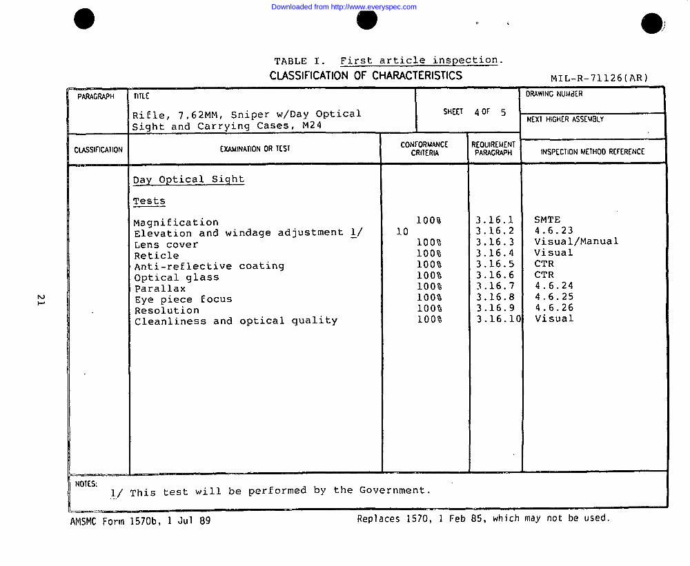
C I ASS l f l CAT I ON EXAM I NAT I ONOR T EST CON~ORMANCE REOU I RDKNTCR I T ERM PARAGRAPH I NSPECT I ONME THOD R [ ~ ERENCE
—
Day Optical Sight
Tests
Magnification 100% 3.16.1 SMTEElevation and windage adjustment ~/ 10 3.16.2 4.6.23Lens cover 100% 3.16.3 Visual/ManualReticle 100% 3.16.4 VisualAnti-reflective coating 100% 3.16.5 CTROptical glass 100% 3.16.6 CTRParallax 100% 3.16.7 4.6.24Eye piece focus 100% 3.16.8 4.6.25Resolution 100% 3.16.9 4.6.26Cleanliness and optical quality 100% 3.16.1 0 Visual
NOT ES :~ / ‘ I ’ h i s t e s t will be performed by the Government.
-—. — --- .AMShlCForm 1570b, 1 Jul 89 Replaces 1570, 1 Feb 85, which may not be used.
Downloaded from http://www.everyspec.com
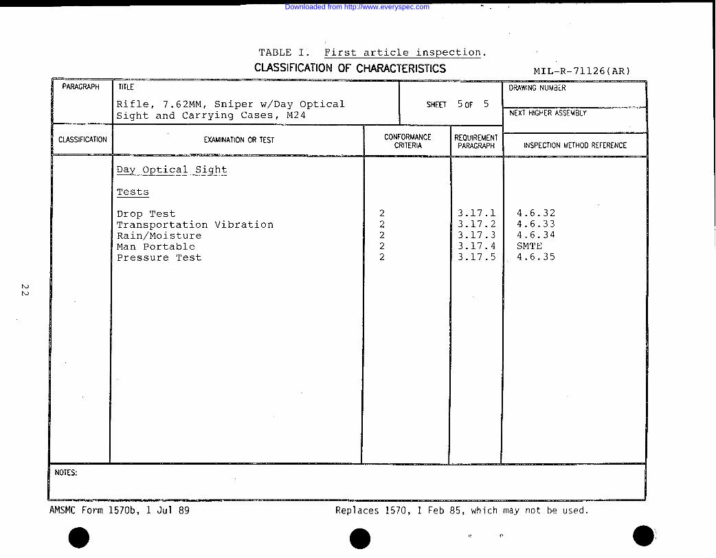
TABLE I . First article inspection.
CLASSIFICATION OF CHARACTERISTICS MT T.–R–71 17 F) (AR).. ----- ,+-ti- ,---. ,
Rifle, 7.62 MM, Sniper w/Day Optical SHE E T 5 0 F 5
Sight and Carrying Cases, M24 NEXT H I GHERASSW3 LY
CLASS I F I CAT I ON EXAM I NAT I ONORT ESTCR I T ER I A PARAGRAPH I NSPECT I ONME THOD RE F ERENCE
Day Optical Sight
Tests
Drop Test 2 3.17.1Transnort.at.ion Vibration_.-_—L--— ---- 2 3.17.2Rain/Moisture 2 3.17.3 4.6.34Man Portable 2 3.17.4 SMTEPressure Test 2 3.17.5 4.6.35
I OT ES :
AMSMC Form 1570b, 1 Jul 89
●
Replaces 1570, 1 Feb 85, which may not be used.
● 1? O
Downloaded from http://www.everyspec.com
.
MIL-R-71126(AR)
I
IIII
I
IIII
!
I
I
I
I
1
I
I
I
I
1
1
I
1
I
I
I
I
I
I
)
I
I
I
I
I
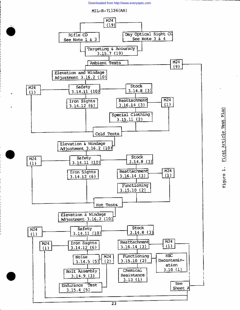
‘M24
I(19)
I
I
I Ambient Tests 1 M24r /01
M24 Safety stock(1) 4 3.14.11(lo) 3.14.8 (3).
IIron Sights Reattacm M243.14.12 (6) 3.16.14 (3) (1).
Special Clothing3.15.11 (2)
Elevation & Windage !
a
Adjustment 3.16.2 (10)
M24 stock
(1) 3.14.8 (3)
Reattachmen~ M243.16.14 (3) (1)
Functioning3.15.10 (2)
4
Hot Tests I
I
M241
Safety(1) 3.14.11 (10)4
Iron Sights3.14.12 (6)
Noise
Reattachment M243.16.14 (3) (1) I
I
Functioning3.15.10(2) Decontamin-
ationChemicai 3.10(1)Resistance \
1 3.13 (1) I
*
Seesheet
I i23
Downloaded from http://www.everyspec.com
MIL-R-71126(AR)
Sheet A
M24
r ’12)
LFungusTest3.11(1)
Drop TestComponent Carrying
Case3.17.1 (2)
Transportation/Vibration3.17.2(2)
~
Rain/Moisture3.17.3(2)
Man Portable3.17.4(2)
Pressure Test3.17.5
(2)
I
)) I
IvDrop TestRifle.3.15.8 (6)
Drop TestDay Optical Sight
3.16.16(3)
CorrosionTest3.12(1)
Drop TestDay Optical Sight
Carrying Case3.16.15 (2)
Figure 2. First Article Test Plan
24
Downloaded from http://www.everyspec.com
MIL-R-71126(AR)
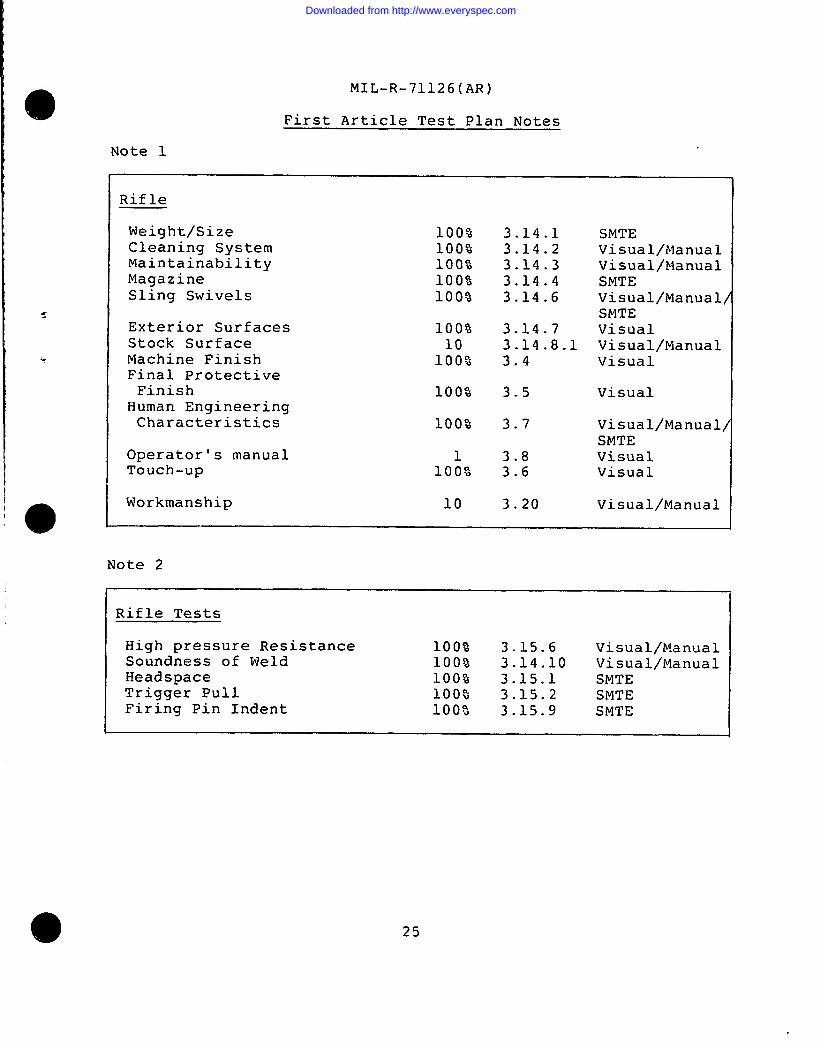
First Article Test Plan Notes
Note 1
Rifle
Weight/SizeCleaning SystemMaintainabilityMagazineSling Swivels
Exterior SurfacesStock SurfaceMachine FinishFinal ProtectiveFinish
Human EngineeringCharacteristics
Operator’s manualTouch-up
Workmanship
100%100%100%100%100%
100%10100%
100%
100%
1100%
10
3.14.13.14.23.14.33.14.43.14.6
3.14.73.14.8.13.4
3.5
3.7
3.83.6
3.20
SMTEVisual/ManualVisual/ManualSMTEVisual/ManualSMTEVisualVisual/ManualVisual
Visual
Visual/ManualSMTEVisualVisual
Visual/Nlanual
Note 2
Rifle Tests
High pressure Resistance 100% 3.15.6 Visual/ManualSoundness of Weld 100$3 3.14.10 VisuallllanualHeadspace 100% 3.15.1 SMTE ‘Trigger Pull 100% 3.15.2 SMTEFiring Pin Indent 100a 3.15.9 SMTE
25
Downloaded from http://www.everyspec.com
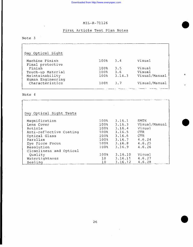
MIL-R-71126
First Article Test Plan Notes
Note 3
Day optical Sight
Machine Finish 100% 3.4 VisualFinal protectiveFinish 100% 3.5 Visual
Touch-up Material 100% 3.6 VisualMaintainability 100% 3.14.3 Visual/ManualHuman EngineeringCharacteristics 100% 3.7 Visual/Manual
Note 4
Day Optical Sight Tests
Magnification 100% 3.16.1 SMTELens Cover 100% 3.16.3 Visual/ManualReticle 100% 3.16.4 VisualAnti-reflective Coating 100% 3.16.5 CTROptical Glass 100% 3.16.6 CTRParallax 100% 3.16.7 4.6.24Eye Piece Focus 100% 3.16.8 4.6.25Resolution 100% 3.16.9 4.6.26Cleanliness and OpticalQuality 100% 3.16.10 Visual
Watertightness 10 3.16.11 4.6.27- Sealing 10 3.16.12 4.6.28
26
Downloaded from http://www.everyspec.com
MIL-R-71126(AR)
4.5 Quality conformance inspection.
4.5.1 Inspection lot formation. The term “inspection lo-t”is defined as a homogeneous collection of units of product fromwhich a representative sample is drawn or which is inspected 100percent to determine conformance with applicable requirements.Units of product selected for inspection shall represent only theinspection lot from which they are drawn and shall not beconstrued to represent any prior or subsequent quantitiespresented for inspection. Homogeneity shall be considered toexis’t provided the inspection lot has been produced by onemanufacturer, in one unchanged process, using the same materialsand methods, in accordance with the same drawings, same drawingrevisions, same specifications and same specification revisions.All material submitted for inspection in accordance with thisspecification shall comply with the homogeneity criteria specifiedherein, regardless of the type of inspection procedure which isbeing applied to determine conformance with requirements.
4.5.1.1 Lot size. The size of the lot shall be inaccordance with MIL-W-13855. The maximum size of a lot shallbe 400.
4.5.1.2 Lot identification. Each inspection lot shall beidentified with a lot number. The reason for rejection of anyinspection lot shall be recorded. When a rejection inspectio~ lotis resubmitted after reconditioning, it shall be identified assuch .
4.5.2 Examinations and tests.
a. Classification of characteristics. Qualityconformance examinations and tests are specified in the followinqClassification of Characteristics paragraphs. The contractor’s -quality program or detailed inspection system shall provideassurance of compliance of all characteristics with the applicabledrawing and specification requirements utilizing as a minimum theconformance criteria specified. When cited herein, attributessampling inspection shall be conducted in accordance with Table IIusing the inspection levels stated in the Classification ofCharacteristics paragraphs. The certification provisions of MIL-W-63150 for Certified Test Reports (CTR) and Certificates ofConformance (COC) shall apply.
27
Downloaded from http://www.everyspec.com
.—
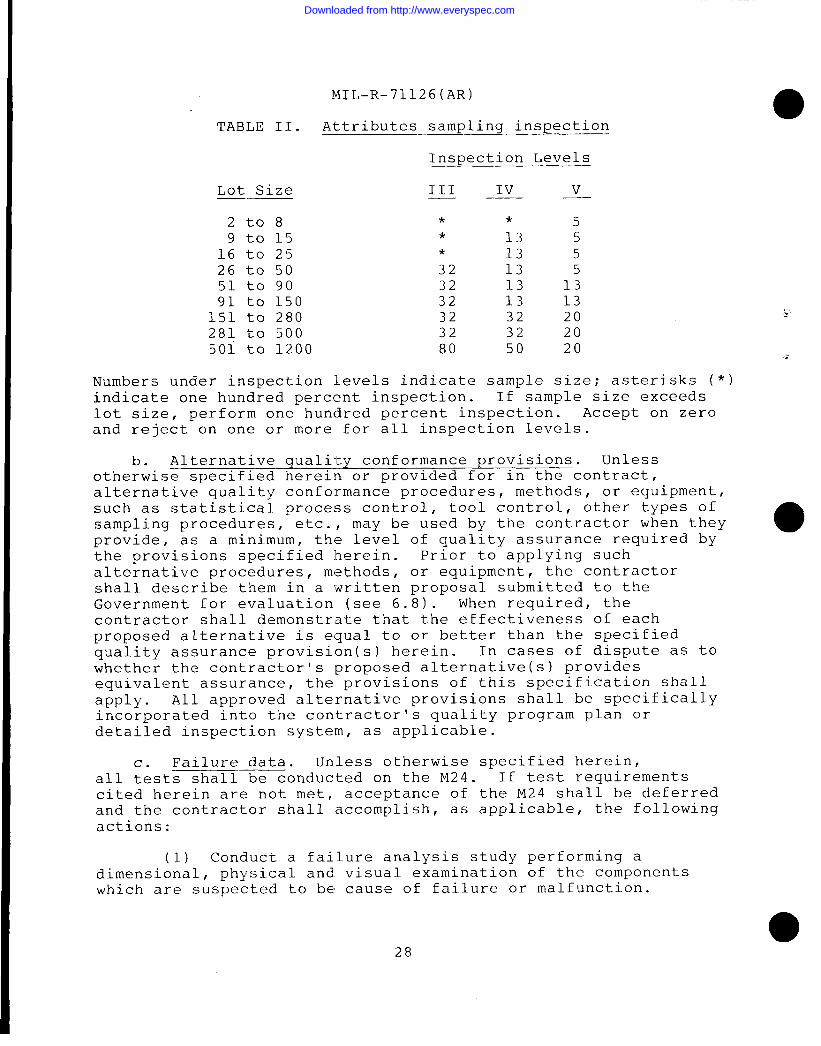
TABLE II.
Lot Size
2t089 to 15
16 to 2526 to 5051 to 9091 to 150
151 to 280281 to 5005oi to 1200
MIL-R-71126(AR)
Attributes sampling inspection
Inspection Levels
III Iv v— . —
* * 5* 13 5* 13 532 13 532 13 1332 13 1332 32 2032 32 2080 50 20
Numbers under inspection levels indicate sample size; asterisks (*)indicate one hundred percent inspection. If sample size exceedslot size, perform one hundred percent inspection. Accept on zeroand reject on one or more for all inspection levels.
b. Alternative qualit~ provisions. Unlessotherwise specified herein or provided for in the contract,alternative quality conformance procedures, methods, or equipment~such as statistical process control, tool control, other types ofsampling procedures, etc. , may be used by the contractor when they ●provide, as a minimum, the level of quality assurance required bythe provisions specified herein. Prior to applying suchalternative procedures, methods, or equipment, the contractorshall describe them in a written proposal submitted to theGovernment for evaluation (see 6.8). When required, thecontractor shall demonstrate that the effectiveness of eachproposed alternative is equal to or better than the specifiedquality assurance provision(s) herein. In cases of dispute as towhether the contractor’s proposed alternative(s) providesequivalent assurance, the provisions of this specification shallapply. All approved alternative provisions shall be specificallyincorporated into the contractor’ s quality program plan ordetailed inspection system, as applicable.
c. Failure data. Unless otherwise specified herein,all tests shall be conducted on the M24. If test requirementscited herein are not met, acceptance of the M24 shall be deferredand the contractor shall accomplish, as applicable, the followingactions:
(1) Conduct a failure analysis study performing adimensional, physical and. visual examination of the componentswhich are suspected to be cause of failure or malfunction.
28
Downloaded from http://www.everyspec.com
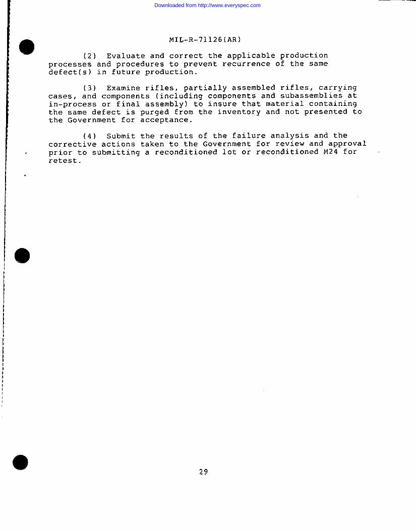
o MIL-R-71126(AR)
(2) Evaluate and correct the applicable productionprocesses and procedures to prevent recurrence of the samedefect(s) in future production.
(3) Examine rifles, partially assembled rifles, carryingcases, and components (including components and subassemblies atin-process or final assembly) to insure that material containingthe same defect is purged from the inventory and not presented tothe Government for acceptance.
(4) Submit the results of the failure analysis and thecorrective actions taken to the Government for review and approval
. prior to submitting a reconditioned lot or reconditioned 1124 for “retest.
.
29
Downloaded from http://www.everyspec.com
b.)o
.
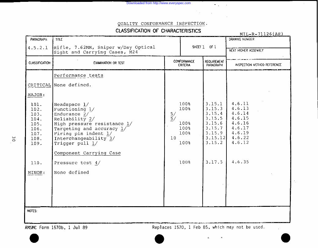
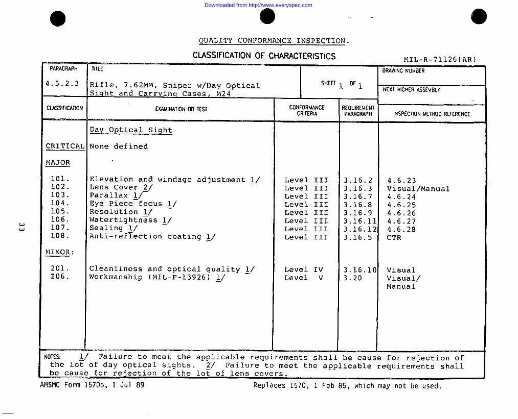
QUALITY CONFORMANCE INSPECTION.
CLASSIFICATION OF CHARACTERISTICSMT T.– R–71 1 ?& (AR)
PARAGRAPH T I T L E DRAW I NGNUM J E I ?
4 .5.2.1 Rifle, 7.62MM, Sniper w\Day Optical SHE E T 1 O F 1
Sight and Carrying Cases, M24NEXT H I GHERASSEUBLY
C I K3 1 F I CAT I ON EY . AM I NAT I ONOR T EST CR I T ER I A I NSPECT I ONME THOD RE F ERENCE
Performance tests
CRITICAL None defined.
MAJOR :
101. Headspace ~/ 100% 3.15.1 4.6.11102. Functioning ~\ 100% 3.15.3 4.6.13
103. Endurance ~/ 5/ 3.15.4 4.6.14104. Reliability ~/ ~/ 3.15.5 4.6.15
105. High pressure resistance ~\ 100% 3.15.6 4.6.16
106. Targeting and accuracy ~/ 100% 3.15.7 4.6.17
10.7. Firing pin indent ~/ 100% 3.15.9 4.6.19
108. Interchangeability ~/ 10 3.15.12 4.6.22
109. Trigger pull :/ 100% 3.15.2 4.6.12
Component Carrying Case
110. Pressure test ~\ 100% 3.17.5 4.6.35
MINOR : None defined
‘ 4 0 T ES :
AMSMC Form 1570b, 1 Jul 89
●
R e p l a c e s 1570, 1 Feb 85, which may not be used
● i? f,,
Downloaded from http://www.everyspec.com
MIL-R-71126(AR)
>/ Failure to meet the applicable requirement shall be cause forrejection of the rifle.
I
[~/ Failure to meet the applicable requirement shall be cause for
f rejection of the lot of rifles.
1~
3/ Interchangeability testing. A sample of ten M24’s from eachInspection lot shall be tested for interchangeability of repair
) parts using the test method specified in 4.6.22. M24’s taken forI
interchangeability testing shall have been found satisfactory in. all other examinations and tests. Hand refinement of parts will -
not be allowed. Failure of any part of the interchange testingspecified in 4.6.22 shall be cause for retest or rejection of the
a represented lot. An interchangeability retest shall be cause forrejection of the represented lot subject to reconditioning andfurther test as a reconditioned lot. A sample of 20 M24s from areconditioned lot shall be tested using the same proceduredescribed above.
~/ Failure to meet the applicable requirement shall be cause forI rejection of the lot of component carrying case.I
o ~\ For the endurance test, the sample size shall be one weaponfor a lot size of 200 or less and two weapons for a lot sizebetween 201 and 400.
31
Downloaded from http://www.everyspec.com
.
QUALITY CONFORMANCE INSPECTION.
CLASSIFICATION OF CHARACTERISTICS MI L-R-71126 (AR)-.——.PARAGRAPH T I T L E DRAW I NGNUMd ER
4 .5.2.2 Rifle, 7.62 MM, Sniper w/Day Optical SHE E T 1 O F 1
Sight and Carrying Cases, M24 NEXT H I GHERASSEMBLY
CLASS I F I CAT I ON EXAM I NAT I ONOR T EST CON F ORMANCE REQU I REMENTCR I T ER I A PARAGRAPH I NSPECT I ONME THOD RE F ERENCE
Rifle
CRITICAL None defined
MAJOR
101. Magnetic Particle Mark ~/ 100% 3.15.6 4.6.16102. Proof Mark ~/ 100% 3.15.6 4.6.16103. Ironsights ~/ Level III 3.14.12 4.6.10.2104. Soundness of Weld ~/ 100% 3.14.10 4.6.8105. Safety 100% 3.14.11 4.6.9.2
MINOR :
201. Machine Finish ~/ Level IV 3.4 Visual202. Final Protective Finish ~/ Level IV 3.5 Visual203. Touch-up Material ~/ Level IV 3.6 Visual204. Stock Surface ~/ Level IV 3.14.8. - Visual/
Manual205. Sling Swivels ~/ Level IV 3.14.6 Visual/
Manual/SMTE206. Workmanship ~/ Level V 3.20 Visual/
Manual
‘ J OT ES : 1 / Failure to meet the applicable requirements shall be cause for rejection ofthe ri~le. ~/ Failure to meet the applicable requirements shall be cause for rejectionof the lot of rifles.
AMSMC Form 1570b, 1 Jul 89 Replaces 1570, 1 Feb 85, which may not be used.
({ .
Downloaded from http://www.everyspec.com
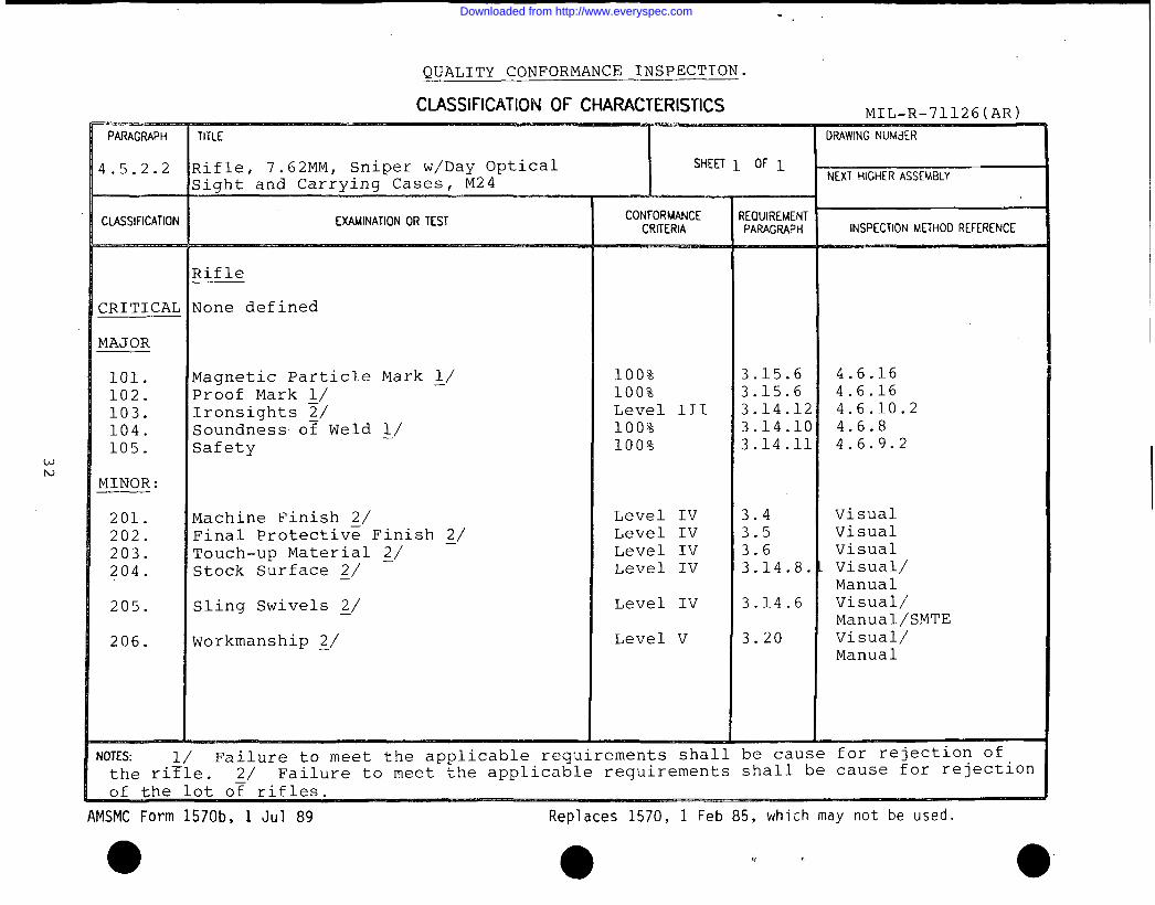
QUALITY CONFORMANCE INSPECTION.
CIJWSIFICATION OF CHARACTERISTICS MT T4-R-7119K(ZIR)
wu
. . . . . . , .. -...-.”,’... ,
PARAGRAPH T I T L E DRAW I NGNUM i l ER
4 . 5 . 2 . 3 R j , f l ~ , 7.62 MM, Sniper w/Day Optical SHE E T ~ O F l
Siqht and Carryinq Cases,NEXT H I GH I RASSEMBLY
M2 4
CLASS l f l CAT I ON Cw I NAT I ON OR T EST cotp;yvJcE REQU I REMENTPARAGRAPH I NSPECT I ONME THOO RE F ERENCE
Day Optical Sight
CRITICAL None defined
MAJOR
101. Elevation and windage adjustment ~/ Level 111 3.16.2 4.6.23102. Lens Cover ~/ Level III 3.16.3 Visual/Manual103. Parallax ~/ Level 111 3.16.7 4.6.24104. Eye Piece focus ~/ Level III 3.16.8 4.6.25105. Resolution >/ Level III 3.16.9 4.6.26106. Watertightness ~/ Level III 3.16.11 4.6.27107. Sealing ~/ Level III 3.16.12 4.6.28108. Anti-reflection coating ~/ Level III 3.16.5 CTR
MINOR :
201. Cleanliness and optical quality ~/ Level IV 3.16.10 Visual206. Workmanship (MIL-F-13926) ~/ Level V 3.20 Visual/
Manual
NOT ES : & / Failure to meet the applicable requirements shall be cause for rejection ofthe lot of day optical sights. ~/ Failure to meet the applicable requirements shall
~ ~au~
AMSMC Form 1570b, 1 Jul 89 Replaces 1570, 1 Feb 85, which may not be used.
Downloaded from http://www.everyspec.com
NIIL-R-71126(AR)
4.6 Methods of inspection.
4.6.1 NBC decontamination. The contractor shall submit alist of all of the materials used in the rifle, sighting systemsand the exterior of the carrying case. The Government will doan engineering study to determine the NBC decontaminationsurvivability of the materials. To be acceptable, all of thematerials shall pass the Government’s study.
4.6.2 Fungus. The fungus resistance test shall beconducted on the rifle, sighting systems and carrying cases inaccordance with MIL–STD–81.O. The test cycle shall be 28 days.
4.6.3 Corrosion resistance. The test shall be performed asspecified in ASTM–B117. Test procedures and equipment shall haveprior approval of the Government.
4.6.3.1 Repair parts. The time for the salt spray testrepair parts shall be the-following:
Maganese phosphate coating: 1 1/2 hoursZinc phosphate coating: 2 hoursProtective finishes on metalcomponents other than thosespecified in 3.5: 96 hours
Upon completion of the test, parts shall be examined forcorrosion. To be acceptable, there shall be no evidence ofcorrosion.
4.6.3.2 Rifle with (W optical sight and componentcarrying case. The rifl= with the day optical sight attached anda closed empty component carrying case shall be subjected to thesalt spray test for 24 hours. The adjustment knobs and lensesshall be exposed. Upon completion of the test the rifle with dayoptical sight and component carrying case shall be examined forcorrosion for information only. The following test shall then beconducted.
4.6.3.3 Targeting and accuracy. The rifle shall be cleanedand lubricated before the start of the test. The rifle and dayoptical sight shall be subjected to the targeting and accuracytest of 4.6.17. To be acceptable, it shall meet the targetingand accuracy requirements of 3.15.7.
4.6.3.4 Reattachment. The rifle with day optical sightshall be tested for reattachment in accordance with 4.6.29. Theday optical sight shall be removed and reattached for a total of10 cycles. To be acceptable, it shall meet the requirements of3.16.14.
34
Downloaded from http://www.everyspec.com
MIL-R-71126(AR)
4.6.3.5 Component carrying case. The hinges shall bechecked for functioning. The component carrying case shall beopened and closed three times. To be acceptable, all of thehinges shall function without binding.
4.6.4 Chemical resistance. The rifle, sighting systemsexcept for the adjustment knobs, lenses and lens cover, and theexterior of the carrying cases shall be tested in accordance with‘TOP 3-2-609. The interior of the carrying case shall be testedfor the chemicals listed in 3.13 in accordance with TOP 3-2-609;
4.6.5 Noise. The noise test shall be conducted on the riflein accordance with MIL-STD-1474. A minimum of 10 rounds shall befired.
4.6.6 Stock. The range of the length of pull shall bechecked using a Government approved gage. If the adjustment isincremental, the length of each increment of adjustment betweenthe range of 12 to 14 inches shall be checked using a Governmentapproved gage. The rifle shall be placed on a table with thestock in the minimum position. A command shall be given to startat the same time a Government approved stopwatch is started. Thestock shall be adjusted to a length of pull of 14 inches minimumusing only the tools available to the operator. The time tocompletion shall be recorded.
To be acceptable, the time to completion shall be less than3 minutes.
The stock shall be adjusted to a length of pull of 14 inches,minimum, using only the tools available to the operator under thefollowing conditions:
a. By a person dressed in NBC clothing.
b. The rifle shall be conditioned for a minimum of fourhours in a cold temperature chamber at -500F + 5oF. A persondressed in cold weather environmental clothin~, with theouter artic mitten removed, shall enter the chamber and the aboveprocedure repeated.
c. The rifle shall be conditioned for a minimum of fourhours in a hot temperature chamber at 145° F ~ 5° F and the aboveprocedure repeated.
4.6.7 Bolt assembly. The rifle shall be placed on a table.A command shall be given to start at the same time a Governmentapproved stopwatch is started. The bolt shall be removed andreinserted. The time shall be recorded. To be acceptable thetime to completion shall be less than one minute.
35
Downloaded from http://www.everyspec.com
MIL-R-71126(AR)
4.6.8 Soundness of weld. Magnetic particle inspection forsoundness of weld shall be performed in accordance with MIL–STD–1949.
4.6.9 Safe~.
4.6.9.1 First artic].e. A primed empty M118 cartridge shallbe inserted into the chamk=r before performing the followingtests:
The safety shall be placed in the safe position. Threeattempts shall be made to fire the rifle. With the shooter ineach of the positions listed in 3.14.11, the shooter shall verifythe position of the safety by looking at it. Next, without,looking the shooter shall verify the position of the safety bytouch . While in each of these positions, the shooter shall changethe position of the safety from safe to fire and back to safewithout moving his hands from the shooting position. To beacceptable the shooter shall perform all of the above tests andthe rifle shall not fire.
With the safety in the safe position, a force gage shall beattached and a force applied parallel to the direction of rotationuntil the safety moves to the fire position. The force shall berecorded. To be acceptable, both forces shall be between 2 and10 pounds. ●
The above procedure with the exception of the force test,shall be repeated under the following conditions:
a. By a person dressed in NBC clothing.
b. The rifle shall be conditioned for a minimum of fourhours in a cold temperature chamber at –500F ~ 5oF. A persondressed in cold weather environmental clothing with the outerartic mitten removed, shall enter the chamber and the aboveprocedure repeated.
c. The rifle shall be conditioned for a minimum of fourhours in a hot temperature chamber at 145° F + 5oF and the aboveprocedure repeated.
—
4.6.9.2 Lot acceptance. Ensure that the weapon is in thecocked position (firing pin head is to the rear) before beginningthis test. The safety shall be placed in the safe position.Three attempts shall be made to fire the weapon. The firing pinhead shall be visually inspected after each attempt to ensure thatit does not fall forward. To be acceptable the firing pin headshall not fall forward on any of the three attempts. The safetyshall then be placed in the fire position. An attempt shall bemade to fire the weapon. If firing pin head falls forward the ●
36
Downloaded from http://www.everyspec.com
MIL-R-71126(AR)
weapon shall be recocked. This procedure shall be repeatedthree times. To be acceptable the firing pin head shall fallforward all three times. Ensure that the weapon is in the cockedposition. The safety shall be placed in the safe position. Threeattempts shall be made to fire the weapon. The firing pin headshall be visually inspected after each attempt to ensure that itdoes not fall forward. To be acceptable the firing pin head shallnot fall forward on any of the three attempts. A force gage shallthen be attached to the safety lever and a force applied parallelto the direction of rotation until the safety moves to the fireposition. The force shall be recorded. The force shall then beapplied in the opposite direction until the safety moves from thefire to the safe position. The force shall be recorded. To” be “acceptable both force readings shall be between 2 and 10 pounds.
4.6.10 Iron sights.
4.6.10.1 First article. A total of six rifles shall be usedfor this test. All six rifles shall be subjected to the testlisted in 4.6.10.2. Two rifles shall then be conditioned in acold temperature chamber (-500 ~ 50F) for a minimum of four hours.A person dressed in cold weather environmental clothing with theouter artic mitten removed, shall enter the chamber and performthe adjustments listed in 4.6.10.1.1. The two rifles shall thenbe conditioned in a hot temperature chamber (+1450 ~ 5oF) for aminimum of four hours. A person shall enter the chamber andperform the procedure listed in 4.6.10.1.1. A person dressed inNBC clothing shall perform the adjustments listed in 4.6.10.1.1 atambient temperature.
4.6.10.1.1 Adjustment. The iron sight azimuth andelevation adjustment shall be adjusted to each extreme twotimes.
4.6.10.1.2 Front sight width. The contractor shall submitthe dimensions with tolerance of the front sight width forGovernment approval. Upon Government approval, this shall be therequirement for checking the front sight width.
4.6.10.2 Lot acceptance. The width of the front sight shallbe checked using a Government approved gage. The iron sightazimuth and elevation adjustment shall be adjusted to each extremetwo times. The full range of azimuth and elevation shall bechecked for detented, audible and tactile clicks. If the ironsights are detachable, the following procedure shall be performed:
The iron sights shall be set to zero. The rifle shall thenbe mounted in a Government approved rigid mount. A Governmentapproved test target shall be positioned at a distance from theweapon and dimensioned such that when viewed through the ironsights, it will represent the tolerance for maximum change in
37
Downloaded from http://www.everyspec.com
MIL-R-71126(AR)
zero. The iron sights shall then be removed and reattached tothe rifle. Upon completion of the test, the target shall beviewed through the iron sights. To be acceptable, the line ofsight shall lie within the tolerance zone on the test target.
4.6.11 Headspace. The rifles shall be gaged for headspaceusing a Government approved headspace gage.
4.6.12 Trigger pull. This test shall be performed usingGovernment approved ~=ction equipment.
4.6.12.1 Minimum load. The trigger pull shall be set to itsminimum force. The rifle shall be cocked and the selector levelshall be placed in the “fire” position. A Government approvedforce gage shall be attached to the trigger. A force shall begradually applied to the center of the trigger and exerted in aline parallel to the axis of the barrel bore until the firingmechanism is released. The force shall be recorded. The aboveprocedure shall be repeated a total of five times. To beacceptable all of the readings shall be within 2 pounds 8 ounces+ 8 ounces.—
4.6.12.1.1 Minimum load after targeting and accuracy. Theabove test shall be performed prior to target~and accuracytesting (4.6.17). The targeting and accuracy test shall then beperformed with the trigc;er pull force set at approximately 4pounds . At the conclus~Lon of target and accuracy testing, thetrigger pull force shall be reset at its minimum setting and theminimum load test shall be repeated.
4.6.12.2 Maximum ILoad. The trigger pull shall be set to itsmaximum force. The above procedure in 4.6.12.1 shall berepeated. To be acceptable all of the readings shall be a minimumof 4 pounds.
4.6.12.3 Retrainability . This test shall be performed aspart of the contractor ’:~process testing. The trigger pullshall be set at its minimum setting and checked in accordancewith 4.6.12.1. The rifle shall be manually cycled and the triggerpulled a total of 50 times. The trigger pull forces shall againbe checked in accordance with 4.6.12.1. To be acceptable all tentrigger pull force readings shall be within 2 pounds 8 ounces + 8ounces. The above procedure shall be repeated at trigger pull–settings of approximately 3 pounds and 4 pounds with theexception that the rifle shall be cycled 20 times. To beacceptable, all trigger pull force readings shall be within arange of + 12 ounces at the 3 pound setting and + 16 ounces at the4 pound s~tting. At the conclusion of the test ~t. four pounds, thetrigger pull force shall be reset at its minimum setting and againchecked in accordance with 4.6.12.1.
38
.
.=
Downloaded from http://www.everyspec.com
MIL-R-71126(AR)
4.6.13 Functioning. During targeting and accuracy (4.6.17), therifle shall be checked to assure that there are no malfunctionsor unserviceable parts or pierced primers. Upon completion ofthe test, the day optical sight shall be checked for cleanlinessand optical quality (3.16.10). In the event of the occurrence ofany stoppages during the functioning test, a retest shall beallowed consisting of firing 100 rounds. To be acceptable, nostoppages, malfunctions, unserviceable parts or pierced primersshall occur during the retest.
4.6.14 Endurance test. The endurance test shall beperformed by firing each rifle with the day optical sightattached, a total of 10,000 rounds. The rifle shall be fired froma Government approved test fixture. The ammunition used for thistest shall be as specified in 3.15.3. All rounds fired shall becounted. The number of rifles used shall be the following:
First Article 5
Lot acceptance 1 (Lot size 200 or less)2 (Lot size 201 to 400)
4.6.14.1 Firing procedure. Firing shall be accomplished ingroups of 30 shots. Firing shall be at the rate of 60 shots perhour for the first 5,000 shots fired. The firing rate after 5,000shots have been fired may vary between 60 shots and 240 shots perhour. The weapon shall be cleaned, decoppered and lubricated at ‘30 round intervals.
4.6.14.2 Replacement of parts . NO parts shall be alteredduring the test. Broken parts that affect function and thoseparts that are worn to the extent they are unserviceable shall bereplaced. The contractor shall provide replacement parts asrequired to complete the test at no additional cost to theGovernment.
4.6.14.3 Magnetic particle inspection. The barrel receiverand bolt shall be maqnetic particle inspected at 2,500 rounds,5,000 rounds and at =very 1~000 rounds thereafter. Magneticparticle inspection shall be done in accordance with MIL-STD-1949.
4.6.14.4 Barrel accuracy. The barrel accuracy shall bechecked after 4940 rounds have been fired. Testing shall beconducted with the rifle held in a Government approved machinerest. The ranges shall be as specified in 3.15.4. Theammunition shall be as specified in 3.15.3. Before the rifle isfired for record, ten shots shall be fired to seat the rifle.Five targets of ten rounds each shall then be fired and theaverage mean radius calculated. The average mean radius must meetthe requirements as specified in 3.15.4.
39
Downloaded from http://www.everyspec.com
MIL-R-71126(AR)
4.6.14.5 Cleaning and lubrication. The rifle shall becleaned and lubricated as specified below.
4.6.14.5.1 Lubrication. The rifle shall be lubricatedusing lubricant in accordance with MIL–L–46000 (LSA) or MIL–L–63460.
4.6.14.5.2 Cleaning. The rifle shall be cleaned using acleaning solvent in accc=dance with MIL–C–372.
4.6.14.6 Retention of point of aim. At the start of theendurance test, the scope mounting bolts shall be torqued asspecified in 4.6.17. The weapon shall be mounted in a machinerest and ten shots shall. be fired to seat the weapon. Fiveconsecutive ten shot groups shall then be fired at five separatetargets, for a total of fifty shots. The same point of aim shallbe retained for all rounds fired. The center of impact for eachten round group shall be calculated. The centroid of the fivecenters of impact shall then be calculated by taking the mean ofthe X and Y coordinates for the five centers of impact. At 440rounds of the endurance test the above procedure shall berepeated. To be acceptable, the calculated centroid of the fivecenters of impact at 440 rounds shall not deviate by more than1.086 minutes of anqle (3.3 inches @ 300 yards, 2.2 inches at 200yards, 2.4 inches a~ 200 meters) from the-calculated centroid at Orounds. The above test shall be repeated over the 4500 roundthrough 4940 round, interval of the endurance test. ●
4.6.15 Reliability test.
shall be calculated based on theOnly failures that are
4.6.15.1 MRBF. The MRBFresults of the endurance test.attributable to either the rifle or the optical day sight and meetthe failure criteria of 3.15.5 shall be counted.
The MRBF shall be calculated based on the following formula:
M.R.B.F. req = Total number of rounds firedTotal number of failures
4.6.15.1.1 Number of failures allowed for first article.Accept on 19 failures or less.
4.6.15.1.2 Number of failures allowed for lot acceptance.
Sample size
12
Accept on 4 failures. or lessAccept on 8 failures or less
40
Downloaded from http://www.everyspec.com
I
I!
,I
I
i
II
II
MIL-R-71126(AR)
4.6.15.2 MRBS . The MRBS shall be calculated based on theresults of the endurance test. Only stoppages that areattributable to the rifle and meet the stoppage criteria of 3;15.5shall be counted.
The MRBS shall be calculated based on the following formula:
M.R.B.S. req = Total number of rounds firedTotal number of stoppages
‘ 4.6.15.2.1 Number of stopp ages allowed for first article.Accept on 36 stoppages or less.
4.6.15.2.2 Number of stopp aqes allowed for lot acceptance.
Sample size
1 Accept on 7 stoppages or less2 Accept on 14 stoppages or less
4.6.16 High pressure resistance. The rifles shall be testedfor high-pressure resistance by firing one Government standardhigh-pressure test cartridge in each rifle. After proof firingthe rifles shall be visually examined for cracks, deformations andother evidence of damage, and cartridge cases shall be visuallyexamined for bulges, splits, rings and other defects caused bydefective barrels. AS a minimum, the barrel, bolt and receivershall be examined by magnetic particle for cracks, and otherevidence of damage, in accordance with MIL-STD-1949. Proof marksand magnetic particle inspection marks shall be applied to riflesthat have passed this test.
4.6.17 Targeting and accuracy. Testing of rifles with dayoptical sight for targeting and accuracy shall be accomplishedwith the rifle held in a Government approved machine rest. Therange shall be as specified in 3.15.7. The ammunition shall beas specified in 3.15.3. All firing shall begin with the magazinefilled to capacity. Before each rifle is fired for record, up toten shots may be fired to foul the bore, seat the weapon, settlethe rifle action and sight the weapon. Five series of ten shotsshall be fired at five separate targets for a total of 50 shots.
The same point of aim shall be retained between all roundsfired. A Government approved stop watch shall be startedcoincident with the firing of the first shot for record. It shallbe stopped as soon as the last shot in the magazine is fired.This procedure shall be repeated until all 50 shots for recordhave been fired. The total time used for firing shall then berecorded. This time is then to be divided. by 50 to determine theaverage firing rate. To be acceptable, the firing rate shall be 3shots per minute or greater.
41
Downloaded from http://www.everyspec.com
MIL-R-71126(AR)
The five targets shall be suitably identified with a commonreference coordinate system to accomplish the measuring requiredto determine the requirements of paragraph 3.15.7. The targetsshall then be checked to determine whether all the targeting andaccuracy requirements of 3.15.7 have been met. To be acceptableeach group of targets shall meet all requirements of 3.15.7.
This test shall be performed with the trigger pull force setat four pounds. Prior tc, the performance of this test, the dayoptical sight mounting nut threads shall be lubricated withlubricant per MIL–L-63460 and the day optical sight shall beremoved form the rifle and reattached a total of 20 times usingthe following procedure:
Removal:
a. Using 1/2 inch box wrench, loosen front ring nut.
b. Using 1/2 inch box wrench, loosen back ring nut.
Reattachment:
a. The back and front right nuts shall be checked forlubrication and smooth mc)vement with respect to the clamp of thering mount. Lubrication and smooth movement shall be assuredbefore proceeding with attachment of the day optical sight. ●
b. Inspection for burrs and foreign matter shall be madebetween the ring nut and the clamp of the ring mount. Any suchburrs or foreign matter found shall be removed prior to telescopeattachment .
c. Finger tighten the back ring nut.
d. Finger tighten the front ring nut.
e. Using 1/2 inch box wrench, tighten the back ring nut1/4 turn (i.e. rotate 90 degrees) .
f. Using 1/2 inch box wrench, tighten the front ring nut1/4 turn (i.e. rotate 90 degrees) .
4.6.17.1 Reticle adjustment. Upon completion of thetargeting and accuracy test (4.6.17), the number of tactileclicks of reticle adjustment between the zeroed position of thewindage (left and right direction) and elevation shall be counted.To be acceptable, the number of clicks of adjustment shall meetthe requirements of 3.15.7.
42
Downloaded from http://www.everyspec.com
1MIL-R-71L26(AR)
4.6.18 Drop test rifle. A total of six rifles are to bedrop tested. Each of the six rifles shall be used for one of sixorientations. The rifles shall be dropped onto a dirt surface.The soil penetration resistance shall be measured at a depth of 1to 1 1/2 inches using a Government approved cone penetrometer. Aminimum of three readings at least six inches apart shall be madein the area the rifle is to be dropped (a maximum of six inchesaway from where the rifle will impact). The safety shall beplaced in the safe position and an empty M118 cartridge insertedin the chamber. The rifle shall then be attached to a contractordesigned Government approved test fixture in the followingorientations; barrel down, butt end down, right side down, leftside down, 45 degree angle with vertical plane - butt end down,and top side down. The rifle shall be released from each of theseorientations and allowed to free fall a minimum distance of five
*- feet onto the dirt surface. Upon completion of this test, eachrifle shall be visually inspected for damager rezeroed and shallthen be subjected to the targeting and accuracy test (4.6.17).
4.6.19 Firing pin indent test. Prior to this test, the boltbody assembly will be cleaned and visually inspected to ensurethat there is no excess braze or other condition which couldinterfere with normal function of the firing pin assembly. Thebolt body assembly will then be lightly lubricated with CLP. Therifles shall be tested for firing pin indent using Government
aapproved inspection equipment. The rifle shall be held in ahorizontal position with the bolt held open. A fixture forholding a copper compression cylinder shall be inserted into thechamber, along with an undeformed cylinder. The bolt shall bemanually returned to battery position and, the trigger pulled toindent the copper from the rifle and the depth of the indent inthe copper cylinder computed by measuring the distance from theoriginal surface of the copper cylinder (before indentation) to thebottom of the firing pin impression. The test shall be repeated 2additional times using a new copper cylinder each time. To beacceptable the firing pin indent in all three cylinders shall beequal to or greater than the firing pin indent requirement of3.15.9.
4.6.20 Temperature extremes. Two rifles with the dayoptical sight shall be used for this test. The rifles shall befired at the rate of 60 shots per hour and cleaned and lubricatedevery 30 rounds. For the cold temperature test, the bolt assemblyfrom each rifle shall be disassembled, cleaned with solvent inaccordance with MIL-C-372, dried and reassembled dry. The riflesshall then be conditioned in a cold temperature chamber at -500 +SoF for a minimum of four hours before testinu beqins. A Rerson–dressed in coldmitten removed,the magazine in
. - .weather environmental clothing with the outer articshall enter the chamber, load the magazine, insertthe rifle or load the rifle, and fire 100 shots
43
Downloaded from http://www.everyspec.com
MIL-R-71126(AR)
with each weapon. [Jpon completion of this test, the day opticalsight shall be checked fc)r looseness. The rifles shall then becleaned and lubricated using LSA (MIL–L–46000) or CLP (MIL–L-63460) . The rifles shall. then be conditioned in a hot temperaturechamber at 1450 + 5oF. A person shall enter the chamber and fire100 shots with each weapc)n. To be acceptable all shots must firewithout any stoppages, as defined in 3.15.5, and the day opticalsight shall not become lclose.
4.6.21 Special clothing. Two rifles shall be used for thistest. A shooter dressed =.B.C. clothing shall load themagazine, ins’ert the magazine in the rifle or load the rifle. Heshall then fire four shots with each rifle. To be acceptable, allshots shall fire without any stoppages attributable to theclothing.
4..6.22 Interchangeability . The M24 shall be tested for theinterchange of repair parts (3.15.2) by disassembling and thenreassembling parts using the parts and pre–arranged systemspecified below. Interchange of parts shall be accomplished bydividing the parts of each M24 into 10 groups of non–matingparts . The 10 groups of non–mating parts shall be based on thecontractor supplied parts list (3.9). The parts shall bedistributed in groups into 10 different trays until each traycontains parts of a complete M24. Groups of parts from the firstM24 shall be taken in order and placed in trays 1 through 10;groups of parts from the second M24 shall be taken in order andplaced in trays 2 through 10 to 1; groups of parts from the thirdM24 shall be taken in order and placed in trays 3 through 10 to 2,etc. Commercial parts such as screws, spring pins, etc., shall beplaced in the same tray as their mating or associated part. Anycommercial part rendered unserviceable by disassembly shall bereplaced without penalty to the interchangeability test. The M24shall be reassembled using only those parts which are in the sametray. The rifle shall then be subjected to the headspace test(4.6.11) and firing pin indent test (4.6.19). The rifle shallthen be subjected to the targeting and accuracy (4.6.17) andfunctioning test (4.6.13).
4.6.23 Elevation and windage adjustment. A Governmentapproved collimator which has a reticle capable of measuring to1/2 minute of angle shall be used for this test. The day opticalsight shall be rigidly mounted to a Government approved testfixture. View through the day optical sight and line up thereticle with the collimator reticle. The elevation and windageknobs shall be rotated as specified in 3.16.2. To be acceptable,the zero position of the day optical sight as defined by theintersection of the vertical and horizontal reticle lines shall nothave moved more than the tolerance specified in 3.16.2.
..
●44
Downloaded from http://www.everyspec.com
I
MIL-R-71126(AR)
4.6.24 Parallax. Parallax shall be checked by sightingthrough the day optical sight and observing a point on the targetat the distance specified in 3.16.7 with respect to a correspondingpoint of the day optical sight reticle in close proximity to theoptical axis. Parallax shall be recognized as any apparentdisplacement of the target image in relation to the reticle imagewhen the observer’s head is moved. The displacement of the targetimage shall not exceed the limit specified in 3.16.7.
4.6.25 Eye piece focus. This test shall be performed withthe aid of a calibrated dioptometer with a magnification of at least3 power (3), and a diopter measuring range of-at least plus and
. minus 4 diopters. Adjust the dioptometer eyepiece for best focus -of the dioptometer reticle and set the dioptometer diopter scale tozero. Adjust the eyepiece of the day optical sight to each
. extreme direction and obtain a clear sharp image of the dayoptical sight reticle while viewing through th~ dioptomete~ todetermine conformance with 3.16.8.
4.6.26 Resolution. This test shall be performed utilizingan auxiliary telescope with a magnification of at least 3 power(3X), a resolving power chart, and a supporting medium to receivethis test equipment as well as the day optical sight to be tested.The resolving power chart shall be either figure I of
‘mMIL-O-13830 or the National Bureau of Standards (NBS) HighContract Resolution Test Chart 1952 that forms a part of NBS.Circular 533. The test method and procedure shall be incompliance with the “Resolution Test” specified in MIL-O-13830.The limit of resolution shall be within the value specified in3.16.9 as determined by viewing through the auxiliary telescope.
4.6.27 Watertightness . The day optical sight shall beplaced in a container of water at ambient temperature andsubjected to a minimum pressure of 17.8 pounds per square inchgage for five minutes. The day optical sight shall then bevisually examined for evidence of moisture penetration. To beacceptable, there shall be no evidence of moisture or fogging.
4.6.28 Sealing. The day optical sight shall be placed inGovernment approved test chamber and the pressure reduced to atleast -10.3 pounds per square inch gage. Once this pressure is
a
reached, it shall be maintained for-a-minimum of 7 172 hours. Atthe end of this time, the vacuum pump shall be turned off and thevalves to the chamber closed. Water vapor shall then beintroduced into the chamber until a condition of water vaporcondensing exists. This condition shall be maintained while thechamber is slowly brought to atmospheric pressure. The total timeof this condition shall be a minimum of 1/2 hour. The dayoptical sight shall then be removed from the chamber and examined
45
Downloaded from http://www.everyspec.com
MIL-R-71126(AR)
for the presence of water vapor within the day optical sight. To●
be acceptable, there shall be no evidence of water vapor withinthe day optical sight.
4.6.29 Reattachmen~. This test shall be ‘performed after thetargeting and accuracy test (4.6.17). Three rifles, with dayoptical sight, shall be used. The.day optical sight shall beremoved and reattached for a total of 180 cycles using theprocedure specified in 4.6.17. Throughout this test the scoperings must be aligned with the same slot of the basemount/receiver from which it was removed. The change in zero ofthe day optical sight, as defined by the intersection of thehorizontal and vertical reticle lines in relation to the bore ofthe rifle, shall be recorded after each of the required 180cycles . An auto–collimator which is accurate to 0.5 seconds ofarc, a muzzled reference mirror rigidly attached to the muzzle ofthe rifle and a light sclurce which will project light through theday optical sight to the collimator shall be used to measure thechange in zero. The distance between the auto–collimator reticleas reflected from the muzzle mirror and the projected day opticalsight reticle is the change in zero. To be acceptable, the changein zero shall not exceed the value specified in 3.16.14.
4.6.30 Day optical. sight carrying case. A total of twoday optical sight carrying cases with the day optical sight insideshall be used for this test. One day optical sight carrying case ●shall be conditioned in a cold temperature chamber (–50° F + 5° F)
, for a minimum of 24 hours. The remaining one day optical =ightcarrying case shall be conditioned in a hot temperature chamber(1450F + 50F) for a mir~imum of 24 hours. The two sets of dayoptical—sight carrying cases shall be subjected to the test in4.6.30.1 either while still inside the chamber or immediatelyafter removal from the c:hamber. If the drop test is performedoutside of the chamber, the test shall be completed within threeminutes of removal from the chamber.
4.6.30.1 Orientations. The day optical sight carrying casewith the day optical sig=inside shall be attached to aGovernment approved test fixture in each of the following sixorientations: top, bottom, two adjacent sides, and two diagonallyopposed corners. The day optical sight carrying case shall bereleased from each of these orientations and allowed to fall aminimum distance of seven feet onto a one inch steel plate backedby concrete. Upon compilation of this test, the day optical sightshall be examined for structural and functional damage. The dayoptical sight shall be subjected to the optical tests (4.6.26,4.6.24 and 4.6.23 (ambient onlY)l the waterti9htness test(4.6.27) and the sealing test (4.6.28).
46
Downloaded from http://www.everyspec.com
MIL-R-71126(AR)
4.6.31 Drop test day optical sight. A total of three dayoptical sights are to be drop tested in accordance with either4.6.31.;. or 4.6.31.2. Each of the three day optical sights shallbe used for one of three orientations.
4.6.31.1 Drop test day optical sight on dirt. The dayoptical sight shall be dropped on a dirt surface. The soilpenetration resistance shall be measured at a depth of 1 to 1 1/2inches using a Government approved cone penetrometer. A minimumof three readings at least six inches apart shall be made in thearea the day optical sight is to be dropped (a maximum of sixinches away from where the day optical sight will impact) . Theday optical sight shall then be attached to a contractor designedGovernment approved test fixture in the following threeorientations: both ends and the knobs pointing down. The dayoptical sight shall be released from each of these orientationsand allowed to free fall a minimum distance of two feet onto thedirt surface. Upon completion of the test, the day optical sightshall be subjected to the optical tests (4.6.23 (ambient only)4.6.24, 4.6.26), the watertightness test (4.6.27) and the sealingtest (4.6.28).
4.6.31.2 Drop test day optical sight on rubber mat. Theday optical sight shall be dropped on a 86 durometer pad, one inchthick, back by concrete. The rubber mat shall be certified thatit meets the proper durometer value. The day optical sight shallthen be attached to a contractor designed Government approved testfixture in the following three orientations: both ends and theknobs pointing down. The day optical sight shall be released fromeach of these orientations and allowed to free fall a minimumdistance of five feet onto the rubber mat. Upon completion of thetest, the day optical sight shall be subjected to the opticaltests (4.6.23 (ambient only) 4.6.24, 4.6.26), the watertightnesstest (4.6.27) and the sealing test (4.6.28).
4.6.32 Droptest component carrying case. A total of twocomponent carrying cases are to be drop tested. One componentcarrying case with its full contents shall be conditioned in acold temperature chamber (-400F ~ 5oF) for a minimum of 24 hours.The remaining one rifle carrying case with its full contents shallbe conditioned in a hot temperature chamber (1450F + 5oF) for aminimum of 24 hours. The two component carrying ca=es with itsfull contents shall be subjected to the test in 4.6.32.1 eitherwhile still inside the chamber or immediately after removal fromthe chamber. If the drop test is performed outside the chamber,the test shall be completed within ten minutes of removal from thechamber.
47
Downloaded from http://www.everyspec.com

MIL-R-71126(AR)
4.6.32.1 Orientations. The component carrying case shall beattached to a Government approved test fixture in each of thefollowing orientations: t~p, bottom, tow adjacent sides and twodiagonally opposed corners. The component carrying case shall bereleased from each of these orientations and allowed to fall aminimum distance of 30 inches onto a one inch steel plate backedby concrete. Upon completion of this test, the component carryingcase shall be visually examined for any structural or functionaldamage. All of the contents shall be examined for any physicaldamage .
4.6.33 Transportation vibration. This test shall beperformed at the completion of the component carrying case droptest. One component carrying case shall be subjected to the coldtemperature transportation vibration test of Method 5019.1 andMethod 5020.1 of Federal Test Method Standard No. 101. Uponcompletion of the test, the component carrying case shall beexamined for structural damage and the rifle and day optical sightshall be examined for physical damage. The component carryingcase and its full contents shall be subjected to the rain/moisturetest (4.6.34) and the rifle shall be subjected to the targetingand accuracy test (4.6.17).
4.6.34 Component carrying case rain/moisture. Thecomponent carrying case with all of its contents inside shall beplaced inside a Government approved rain chamber. Rain and wind ●&hall be applied at the rate-~pecified in 3.17.3 for 1/2 hour.Upon completion of the test, the rifle shall be removed from thecase and examined for wetness. To be acceptable there shall be nowetness inside the case.
4.6.35 Component carrying case pressure test. The pressurerelief value shall be =moved from the carryinq case and asuitable adaptor shall be installed which w~ll-permit drycompressed air to pressurize the case. A pressure regulatorshall be used to prevent over pressurization. The case shall bepressurized to a positive pressure of 0.50 + 0.05 psig (13.8 ~ 1.4in . of water) and the air supply shut off. ‘The pressure shall beallowed to stabilize for 15 minutes. If the pressure fallsoutside 0.50 + 0.05 psig range during the stabilization period,the case shali be repressurized to 0.50 ~ 0.05 psig. Record theactual pressure in the case. Allow the container to remain inthis condition for 6 minutes and record the pressure. If thepressure drop after 6 minutes exceeds the requirement in 3.17.5the case shall be rejected.
48
Downloaded from http://www.everyspec.com
MIL-R-71126(AR)
5. PACKAGING
5.1 Packaging requirements. The requirements for packagingshall be in accordance with ASTM-D3951. The quantity of unit packshall be one each.
5.2 Marking. Marking shall be in accordance withMIL-STD-129 .
6. NOTES
(This section contains information of a general orexplanatory nature that may be helpful, but is not mandatory) .
6.1 Intended use. The M24 furnished to this specificationare intended for sniper purposes.
6.2 Acquisition requirements. Procurement documents shouldspecify the following:
a. Title, number, and date of this specification.
b. Issue of DOD I SS to be cited in the solicitation, andif required, the specific issue of individual documents referenced(see 2.1.2).
c. Requirements for first article (see 3.1).
d. Final protective finish, if other than specified (see3.5).
e. Block of serial numbers (see 3.19).
f. Level of packaging and packing (see Section 5).
Responsibilities for furnishing acceptance inspectionequipme~~, if other than specified (see 6.3) .
h. Disposition instructions for endurance tested riflesand first article rifles.
i. P41L-I-45208 as the applicable higher level contractquality requirement.
6.3 Submission of contractor inspection equipment designsfor approval. Inspection equipment designs are of two types -Government Special Inspection Equipment (SIE) designs andcontractor designs. SIE designs are designated by drawing numbersunder the “Method of Inspection” heading in Section 4. Designresponsibility for all other inspection equipment is assigned to
49
Downloaded from http://www.everyspec.com
NIIL-R-71126(AR)
the contractor. However, the contractor need not furnish anydesign when a complete Government SIE 49 design is part of theTechnical Data Package (TDP). Unless otherwise specified, thecontractor may submit alternate or modified contractor designs ofSIE in accordance with 6.3.2 and 6.3.3 should he elect to do so.
6.3.1 SIE designs. SIE designs may consist of any of thefollowing:
a. Detailed drawings which completely depict allinformation necessary for the fabrication and use of the item ofinspection equipment.
b. A source control drawing or a specification controldrawing as defined in the Contract Data Requirements List (DD Form1423) .
c. An envelope drawing, as defined in DOD–STD–1OO, whichestablishes the criteria which a detailed design shall meet. Whenenvelope drawings are specified, the contractor shall preparedesigns which comply with the criteria therein.
6.3.2 Contractor designs. Contractor designs arerequired for all inspection equipment for which SIE designs arenot specified and may include commercial equipment which thecontractor proposes to use. (Commercial equipment is defined as ●unmodified equipment which is cataloged and available for purchaseby the general public). contractor designs shall includeappropriate operating instructions, calibration procedures andmaintenance procedures. (Commercial equipment shall be fullydescribed by catalog listing or other means which providesufficient information to permit identification and evaluation bythe Government and may include illustration and engineering data.Designs shall be prepared for any special fixture(s) required tobe used with commercial equipment, or with SIE designs if nototherwise covered thereby (see 6.3.lc) . Designs shall be of thecategory and form specified in the Contract Data RequirementsLists (DD Form 1423).
The specification number, paragraph number, and defectnumber from Section 4 shall be referenced on each contractordesign together with the component or assembly drawing number,revision letter and date to which the specific design applies.
6.4 Definitions .
50
Downloaded from http://www.everyspec.com
MIL-R-71126(AR)
6.4.1 Contractor. Unless otherwise specified, the workContractor used throughout this or the item detail specificationshall mean any supplier or producer of items or mate~ial to theGovernment. This shall include commercial contractors, sub-contractors, Government Owned, Contractor Operated (GOCO) andGovernment Owned, Government Operated (GOGO) plants.
6.4.2 Technical data package (TDP). A technical descriptionof an item adequate for use in procurement. The descriptiondefines the required design configuration and assures adequacy ofitem performance. It consists of all applicable technical datasuch as plans, drawings, and associated lists, specifications,standards, models, performance requirements, quality assuranceprovisions, and packaging data.
6.4.3 Critical defect. A defect that judgement andexperience indicate is likely to result in hazardous or unsafeconditions for individuals using, maintaining, or depending uponproduct; or a defect that jcdgement and experience indicate islikely to prevent performance and of the tactical function of amajor end item such as an aircraft, tank, land vehicle, missile,artillery, or other major weapon system.
6.4.4 Special defect. A defect, other than Critical, thatjudgement and experience indicate may, depending upon the degreeof variance from the design, requirement:
a. Result in hazardous or unsafe conditions forindividuals using, maintaining or depending upon the product or
b. Prevent performance of the tactical function of a majorend item.
6.5 Test firing facilities and operating procedures. Testfiring facilities and operating procedures should be designed bythe contractor in conformance with local, state, and federalregulations, they should be suitable for carrying out prescribedfiring tests and insure the safety of operating and visitingpersonnel. Copies of these contractor designs should be forwardedto the contracting officer.
6.6 Drawings. Drawings listed in Section 2 of thisspecification under the heading US Army Armament Research,Development and Engineering Center (ARDEC) may also includedrawings prepared by and identified as, Edgewood Arsenal, NATICKLabs, Frankford Arsenal, Rock Island Arsenal, Picatinny Arsenalor US Army Armament Research and Development Command (ARRADCOM)drawings. Technical data originally prepared by these activitiesis now under the cognizance of ARDEC.
51
Downloaded from http://www.everyspec.com
M1L-R-71126(AR)
6.7 Subject term (key word) listing.
Sma l l caliber weaponsSniper weaponsMarksmanship rifles
6.8 Submission of alternative quality conformanceprovisions . Unless otherwise specified in the contract, proposedalternative quality conformance provisions will be submitted bythe contractor for evaluation by the technical activityresponsible for the preparation of this specification.
Custodian,,.?
Preparing activity:Army–AR Army–AR
*(project 1OO5-A768)
52
Downloaded from http://www.everyspec.com
STAIWARDIZATION DOCUMENT IMPROVEMEIW PROPOSAL
1. The preparing rictivity must complete blocks 1, 2, 3, and 8. In block 1, both the document number and revtsionletter should be ~iven.
2. The submitter of this form must complete blocks 4, 5, 6, end 7.3. The preparing activity must provide a reply within 30 deys from receipt of the form.NOTE: This form may not be used to request copies of documents, nor to request waivers, or c!atification efrequirements on current contracts. Comments submitted on this form do not constitute or imply authorization towaive any portion of the referenced document(s) or to emend contractual requirements.
i#fie6~tiENb..AC~ANGE: 1. 00C”MENT NUMBER 2. DOCUMENT OATE (YYMMOOJ
:.+,.,,.,:;,l;<;.,,.>:.,.:.,,:..,,. .:..,.,,. .,, , , ,.
3. OOCUMSNT TITLE
4. NATURE OF CHANGE (&ntMy paragra~ rwmbcw m fmti CaPOSfM rowritol If aosdwo. AttacfI Oatra IWWX$ if rwdd. )
15. REASON FOR RECOMMENDATION
- -------- . . ..a. NAME (&sf. f%m, &fMdla bwkiol] b. ORGANIZATION
)
c. ADORESS (ncuoa Z@ Q&) d. TELEPHONE (11’Wu&2 Area CC!@ 7. OATS SUmxn-mo
(1) Cat’nmorclot@lwh400)
(2)AUTOVON[tf app/bmIo)
& PRSPARING ACTMW
● ✍ NAME 1b. TELEPHONE (6!cIM0 MOO CO@)
(1) Camrnorclciti (z) AUTOVON
ic. AooaEss (hchJd92P -)
IWYOU DO NOT RECEIVS A REPLY WITHIN 45 OAYS, CONTACT:
Odonso Ouolitw and $landardizotion Office
eD Form 1426, OCT 89
1 S303 Loosbwg iiko, Suito 1403, Falls Church, VA =1-34S$Tok?Phoiw ~703) 7S+ZM0 AIJTOVOhJ 2S%3340
Previouseditionsare obwlele. ma/2m
1
I
I
I
Downloaded from http://www.everyspec.com