MILITARY FOLDING BRIDGES AS AN ALTERNATIVE TO...
12
3-2016 PROBLEMY EKSPLOATACJI – MAINTENANCE PROBLEMS 53 Karolina DROZDOWSKA The Department of Roads and Bridges, Faculty of Civil Engineering and Architecture Opole University of Technology [email protected]; [email protected] MILITARY FOLDING BRIDGES AS AN ALTERNATIVE TO TRADITIONAL BRIDGE DESIGNS INCLUDING ENGINEERING DESIGN AND AN ANALYSIS OF THE CAPACITY OF THE SELECTED METHOD OF THE ADAPTATION OF THE COLLAPSIBLE STRUCTURE Key words Military bridge folding MS-54, military bridge folding MS-22-80, adaptation, numerical analysis, permanent bridge. Abstract The article deals with the problem of bridges that were destroyed by natural disasters, i.e. flooding. The article describes the need for the rapid improvement of the communication of traffic, and it provides an example of the village Radochów, which rebuilt a destroyed bridge using elements of a folding MS-54 military bridge. This example demonstrates how to adapt the structure, and it provides construction drawings, and numerical calculations. In the following, another structure adopting the folding MS-22-80 is proposed. The proposed concept is different from the existing modular solutions
Transcript of MILITARY FOLDING BRIDGES AS AN ALTERNATIVE TO...

3-2016 PROBLEMY EKSPLOATACJI – MAINTENANCE PROBLEMS
53
Karolina DROZDOWSKA The Department of Roads and Bridges, Faculty of Civil Engineering and Architecture Opole University of Technology [email protected]; [email protected]
MILITARY FOLDING BRIDGES AS AN ALTERNATIVE TO TRADITIONAL BRIDGE DESIGNS INCLUDING
ENGINEERING DESIGN AND AN ANALYSIS OF THE CAPACITY OF THE SELECTED METHOD
OF THE ADAPTATION OF THE COLLAPSIBLE STRUCTURE
Key words
Military bridge folding MS-54, military bridge folding MS-22-80, adaptation, numerical analysis, permanent bridge.
Abstract
The article deals with the problem of bridges that were destroyed by natural disasters, i.e. flooding. The article describes the need for the rapid improvement of the communication of traffic, and it provides an example of the village Radochów, which rebuilt a destroyed bridge using elements of a folding MS-54 military bridge. This example demonstrates how to adapt the structure, and it provides construction drawings, and numerical calculations.
In the following, another structure adopting the folding MS-22-80 is proposed. The proposed concept is different from the existing modular solutions
PROBLEMY EKSPLOATACJI – MAINTENANCE PROBLEMS 3-2016
54
because it created a computer model for the bridge spans that range from 15 to 33 meters. The proposed adaptation of the structure allowed obtaining the maximum span of the bridge of 21 meters which is the true limit of bearing capacity and deflection structure. The conclusion highlights the need for further research on this type of construction, based on the more complex numerical models.
Introduction
The current weather situation, both at home and in the world, causes many natural disasters. The memorable flood in 1997 caused a lot damage in the tributary of the Oder River. The greatest damage was recorded in mountain areas. Flooding rivers damaged or entirely destroyed many objects and numerous sections of roads and railways. Much of it hampered or paralysed transportation in south-west Poland. Road-bridge engineers need to immediately restore the transportation systems.
When a permanent object is a destroyed bridge, it paralyzes traffic, which needs to be unblocked in order to ensure the free movement of vehicles and pedestrians. The costs of the reconstruction in shortest possible time favour the search for alternatives for the construction of bridges. A good solution seems to be adopting military bridges for these crossings; therefore, using folding military bridges is justified, and they are becoming a significant solution.
1. Example of an retractable military bridge adapted to permanent use
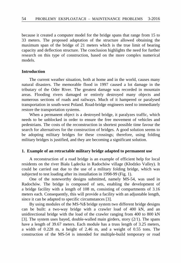
A reconstruction of a road bridge is an example of efficient help for local residents on the river Biała Lądecka in Radochów village (Kłodzko Valley). It could be carried out due to the use of a military folding bridge, which was subjected to test loading after its installation in 1998-99 (Fig. 1).
One of the noteworthy designs submitted, namely MS-54, was used in Radochów. The bridge is composed of sets, enabling the development of a bridge facility with a length of 108 m, consisting of compartments of 3.16 meters each. Consequently, this will provide a facility with an adjustable length, since it can be adapted to specific circumstances [3].
By using modules of the MS-%$ bridge system two different bridge designs can be built: a two-way bridge with a crawler load of 400 kN, and an unidirectional bridge with the load of the crawler ranging from 400 to 800 kN [3]. The system uses bayed, double-walled main girders, story (2/1). The spans have a length of 39.67 meters. Each module has a truss length of 3.25 meters, a width of 0.228 m, a height of 2.46 m, and a weight of 0.55 tons. The construction of the MS-54 is intended for multiple-build temporary or road
3-2016 PROBLEMY EKSPLOATACJI – MAINTENANCE PROBLEMS
55
Fig. 1. A View of tested bridge after completion and the location in Poland
bridge bypasses, with a two-way roadway, with a standard width of 6.00 m, curbs 2 × 0.25 m, and sidewalks of 2 × 0.75 m, located outside the main girders.
1.1. Description of the construction of the new bridge and adaptation works
In place of the destroyed bridge, the military used a collapsible MS-54 with a span length equal to 33.00 m and a width of 5.92 m of usable road (Fig. 2). Adaptation of the bridge consisted mainly of the "classic" exchange platform on the bridge in the form of a steel orthotropic plate with added brackets for walkways with a width of 1.50 m each. This treatment also affected the additional stiffening of the whole structure [5].
Joining the adapted elements established a minimum interference with the existing structural system of the bearing structure of the bridge, MS-54, by using the existing structural elements to the maximum extent [5]. Due to the relatively small width of 6.00 m, it was not possible to design full-scale pavements for pedestrians within the span [4]. Therefore, the addition of a cantilever construction provided new external sidewalks.

PROBLEMY EKSPLOATACJI – MAINTENANCE PROBLEMS 3-2016
56
Fig. 2. Cross-section of the folding MS-54-bridge adapted for permanent use in Radochów
In this design, the nodes connecting truss segments (main girders), as well
as the cross members, were stiffened to eliminate the influence of the clearance of mounting, which is typical for the spans of folding bridges. Additionally, the grate bridge was connected with M20 high-strength bolts that connected joints, brackets, and sections in the middle. The grate bridge was stiffened by welding the elements of the beams with cross members and a new orthotropic plate bridge. Using an existing system of openwork crossbeams and stringers, a bridge in the form of a steel orthotropic plate was constructed. The platform, which is completely welded, is composed of sheet metal transversely ribbed with the ribs resting on the upper stringers of the existing shelves (Fig. 2).
1.2. Description of computational analysis
Numerical calculations were carried out that were then compared with the results obtained during tests on the real object.
Calculations were performed for the flat and spatial MES models of the bridge, using bar-, beam- and shell-type finite elements. The main attention was paid to modelling the hinges - the truss-modules connectors, which play an important role in the global deformation state of the structure (Fig. 3).
The following assumptions were made for calculations: – Calculations are to be performed using MES in Robot Millennium. – Finite element calculations are used for the types of rods and beams. – Calculations of the beam sections of openwork webs are omitted. – In 2D models, loads on the bridge, including vehicles, are summarized
as concentrated forces at the nodes of lattice girders. – In 3D models, the loads on the bridge, including vehicles, are
summarized as elements of grilled flat.

3-2016 PROBLEMY EKSPLOATACJI – MAINTENANCE PROBLEMS
57
Fig. 3. Summary of the computational models used: a) The 2D model of the truss girder; b) The
2D model of the truss girder with the deck; and, c) The 3D model of truss girders with a grid platform
JELCZ 640 KAMAZ 5511
JELCZ 640 KAMAZ 5511
260
260
3150
SCHEME "A"
SCHEME "B"
SCHEME "C"
KAMAZ 5511 JELCZ 640
Fig. 4. Calculations involving considered alternatives of the test load of the folding MS-54
bridge, adopted for a permanent object

PROBLEMY EKSPLOATACJI – MAINTENANCE PROBLEMS 3-2016
58
Table 1. Comparison of normal stresses (MPa) in elements of structural computational models
Results from model Loading scheme
Structural member
2D 2D with deck 3D
“A” scheme
Truss Stringer
Cross-beam
92.53 50.53 42.24
70.82 31.78 11.98
“B” scheme Truss
Stringer Cross-beam
120.92 68.38 48.12
93.23 34.45 12.02
“C” scheme Truss
Stringer Cross-beam
132.85 79.80 127.79
98.64 103.30 22.28
The computational model was subjected to static loads, being equivalent to
real bridge loading under field tests, and also to standard loads for the purpose of comparisons. Three outlines of test loading were taken into consideration. Received results were compared in Table 1 and presented in graphical form (Fig. 4), listing stresses and displacements in the elements and nodes of the main girders, crossbeams, and stringers.
Special attention has been paid to comparing the results of calculations with those estimated from unique field tests of this object conducted by the Mostar Company and Division of Roads and Bridges from Opole University of Technology. Performed calculations showed slight differences, resulting from adopted research methods about the determined accuracy.
Calculations confirmed that the structure of the folding MS-54 bridge is able to carry loads corresponding to Class C construction (according to Polish Standards) and, with a modernised deck, it can effectively perform the functions of a permanent road bridge [6].
Accordingly, the author decided to develop a new concept of a military bridge adaptation on other types of military constructions, such as MS-22-80.
2. Proposal for the adaptation of MS-22-80 bridge for a permanent object
The general approach taken for the modernization of a folding MS-22-80 bridge applies the following assumptions:
– It is acceptable to weld new elements to modular elements. – The use of new components, i.e. all kinds of rolled elements (profiles,
flat bars, etc.) is encouraged. – The primary goal is to ensure an extension of the exploitation period of
the roadway. – The concepts focused exclusively on the modernization of the
supporting structure of the bridge.
3-2016 PROBLEMY EKSPLOATACJI – MAINTENANCE PROBLEMS
59
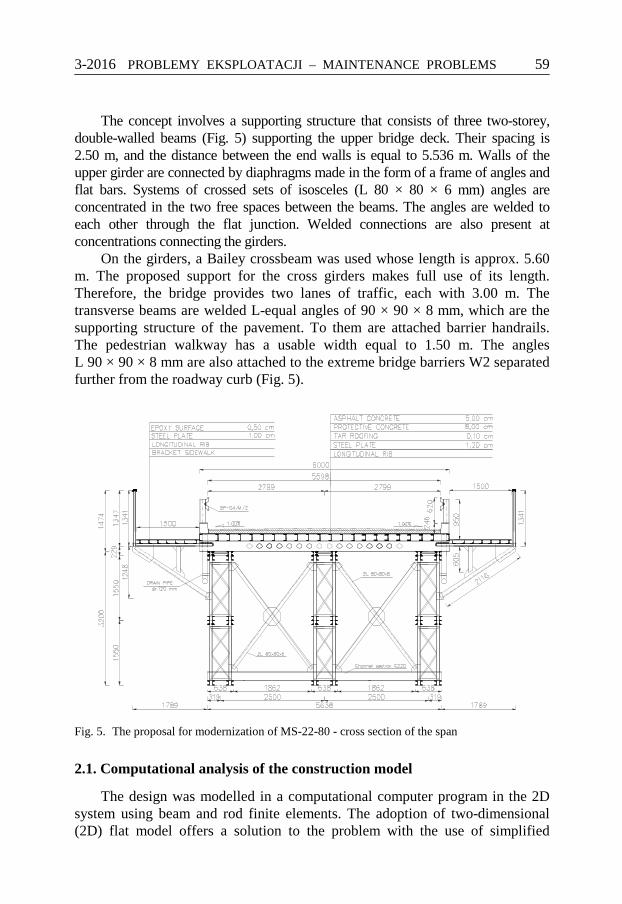
The concept involves a supporting structure that consists of three two-storey, double-walled beams (Fig. 5) supporting the upper bridge deck. Their spacing is 2.50 m, and the distance between the end walls is equal to 5.536 m. Walls of the upper girder are connected by diaphragms made in the form of a frame of angles and flat bars. Systems of crossed sets of isosceles (L 80 × 80 × 6 mm) angles are concentrated in the two free spaces between the beams. The angles are welded to each other through the flat junction. Welded connections are also present at concentrations connecting the girders.
On the girders, a Bailey crossbeam was used whose length is approx. 5.60 m. The proposed support for the cross girders makes full use of its length. Therefore, the bridge provides two lanes of traffic, each with 3.00 m. The transverse beams are welded L-equal angles of 90 × 90 × 8 mm, which are the supporting structure of the pavement. To them are attached barrier handrails. The pedestrian walkway has a usable width equal to 1.50 m. The angles L 90 × 90 × 8 mm are also attached to the extreme bridge barriers W2 separated further from the roadway curb (Fig. 5).
Fig. 5. The proposal for modernization of MS-22-80 - cross section of the span
2.1. Computational analysis of the construction model
The design was modelled in a computational computer program in the 2D system using beam and rod finite elements. The adoption of two-dimensional (2D) flat model offers a solution to the problem with the use of simplified
PROBLEMY EKSPLOATACJI – MAINTENANCE PROBLEMS 3-2016
60
calculations. Positive results can provide grounds for the development and verification of the adopted model in more detail.
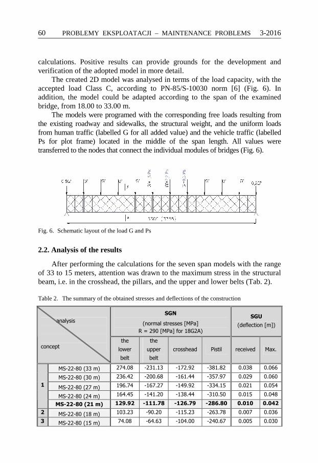
The created 2D model was analysed in terms of the load capacity, with the accepted load Class C, according to PN-85/S-10030 norm [6] (Fig. 6). In addition, the model could be adapted according to the span of the examined bridge, from 18.00 to 33.00 m.
The models were programed with the corresponding free loads resulting from the existing roadway and sidewalks, the structural weight, and the uniform loads from human traffic (labelled G for all added value) and the vehicle traffic (labelled Ps for plot frame) located in the middle of the span length. All values were transferred to the nodes that connect the individual modules of bridges (Fig. 6).
Fig. 6. Schematic layout of the load G and Ps
2.2. Analysis of the results
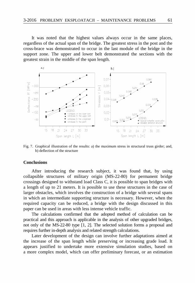
After performing the calculations for the seven span models with the range of 33 to 15 meters, attention was drawn to the maximum stress in the structural beam, i.e. in the crosshead, the pillars, and the upper and lower belts (Tab. 2).
Table 2. The summary of the obtained stresses and deflections of the construction
SGN
(normal stresses [MPa]
R = 290 [MPa] for 18G2A)
SGU
(deflection [m]) analysis
concept the
lower
belt
the
upper
belt
crosshead Pistil received Max.
MS-22-80 (33 m) 274.08 -231.13 -172.92 -381.82 0.038 0.066
MS-22-80 (30 m) 236.42 -200.68 -161.44 -357.97 0.029 0.060
MS-22-80 (27 m) 196.74 -167.27 -149.92 -334.15 0.021 0.054
MS-22-80 (24 m) 164.45 -141.20 -138.44 -310.50 0.015 0.048
1
MS-22-80 (21 m) 129.92 -111.78 -126.79 -286.80 0.010 0.042
2 MS-22-80 (18 m) 103.23 -90.20 -115.23 -263.78 0.007 0.036
3 MS-22-80 (15 m) 74.08 -64.63 -104.00 -240.67 0.005 0.030
3-2016 PROBLEMY EKSPLOATACJI – MAINTENANCE PROBLEMS
61
It was noted that the highest values always occur in the same places, regardless of the actual span of the bridge. The greatest stress in the post and the cross-brace was demonstrated to occur in the last module of the bridge in the support zone. The upper and lower belt demonstrated the sections with the greatest strain in the middle of the span length.
Fig. 7. Graphical illustration of the results: a) the maximum stress in structural truss girder; and,
b) deflection of the structure
Conclusions
After introducing the research subject, it was found that, by using collapsible structures of military origin (MS-22-80) for permanent bridge crossings designed to withstand load Class C, it is possible to span bridges with a length of up to 21 meters. It is possible to use these structures in the case of larger obstacles, which involves the construction of a bridge with several spans in which an intermediate supporting structure is necessary. However, when the required capacity can be reduced, a bridge with the design discussed in this paper can be used in areas with less intense vehicle traffic.
The calculations confirmed that the adopted method of calculation can be practical and this approach is applicable in the analysis of other upgraded bridges, not only of the MS-22-80 type [1, 2]. The selected solution forms a proposal and requires further in-depth analysis and related strength calculations.
Later development of the design can involve further adaptations aimed at the increase of the span length while preserving or increasing grade load. It appears justified to undertake more extensive simulation studies, based on a more complex model, which can offer preliminary forecast, or an estimation
PROBLEMY EKSPLOATACJI – MAINTENANCE PROBLEMS 3-2016
62
regarding the possibility of the building of a bridge based on the presented design or one including a necessary degree of modernization.
References
1. Drozdowska K., 2012, Propozycja adaptacji konstrukcji wojskowego mostu składanego dms-65 do potrzeb cywilnego budownictwa komunikacyjnego, czasopismo Inżynieria i Budownictwo. 3/2012 s. 46–47.
2. Drozdowska K., Koncepcja adaptacji wojskowego mostu składanego dms-65 na obiekt stały, Autobusy, Technika, Eksploatacja, Systemy Transportowe, 6/2016.
3. MARSZAŁEK J. i inni: Mosty składane. Projektowanie, budowa i eksplo-atacja. Wojskowa Akademia Techniczna w Warszawie, GDDKiA, Warszawa 2005.
4. Mańko Z., Kamyk Z., Jakiel P., Michalski J.: Ocena stanu technicznego i przydatności do wykorzystania stalowych elementów konstrukcji mostu składanego na stały most drogowy przez rzekę Białą Lądecką w miejscowości Radochów o długości całkowitej 33 m. Zakład Budowlany BAR-BUD w Bystrzycy Kłodzkiej, Centrum Naukowo-Badawcze Rozwoju Budownictwa „Mostar”, Wrocław 1998.
5. Mańko Z., Jakiel P., Kamyk Z.: Opracowanie projektu budowlanego stałego stalowego mostu składanego typu MS-54 o konstrukcji kratownicowej wraz z podporami w Radochowie. Centrum Naukowo- -Badawcze Rozwoju Budownictwa „Mostar”, Wrocław 1998.
6. PN-S-10030. 1985 Obiekty mostowe. Obciążenia.
Wojskowe mosty składane jako alternatywa dla stałych obiektów inżynieryjnych. Analiza nośności wybranego sposobu adaptacji konstrukcji składanej
Słowa kluczowe
Wojskowy most składany MS-54, wojskowy most składany MS-22-80, adaptacja, analiza numeryczna, most stały.
Streszczenie
W artykule podjęty został problem przepraw mostowych, które uległy zniszczeniu w wyniku klęsk żywiołowych, tj. powodzi. Opisano konieczność szybkiego usprawnienia ruchu komunikacyjnego i podano przykład miejscowości Radochów, w której odbudowano zniszczony most z użyciem

3-2016 PROBLEMY EKSPLOATACJI – MAINTENANCE PROBLEMS
63
elementów wojskowego mostu składanego MS-54. Przedstawiono sposób adaptacji, rysunki konstrukcyjne, obliczenia numeryczne.
W dalszej części zaproponowano możliwość zaadaptowania innej konstrukcji składanej MS-22-80. Zaproponowana koncepcja różni się od dotychczasowych modułowych rozwiązań. W programie komputerowym opracowano model dla przęsła mostu o rozpiętości od 15 do 33 metrów. Zaproponowana adaptacja konstrukcji pozwoliła na uzyskanie maksymalnej rozpiętości mostu – 21 metrów, dla której spełniony jest stan graniczny nośności i stan graniczny użytkowalności. Podsumowując, zwrócono uwagę na konieczności prowadzenia dalszych badań tego typu konstrukcji w oparciu o bardziej złożone modele numeryczne.

PROBLEMY EKSPLOATACJI – MAINTENANCE PROBLEMS 3-2016
64