Milestone #2 Project Proposal Group 4 Victoria Jefferson Reece Spencer Andy Jeanthanor Yanira Torres...
37
Milestone #2 Project Proposal Group 4 Victoria Jefferson Reece Spencer Andy Jeanthanor Yanira Torres Kevin Miles Tadamitsu Byrne 1
Transcript of Milestone #2 Project Proposal Group 4 Victoria Jefferson Reece Spencer Andy Jeanthanor Yanira Torres...
Milestone #2 Project ProposalGroup 4Victoria Jefferson Reece SpencerAndy Jeanthanor Yanira TorresKevin Miles Tadamitsu Byrne
1

Problem StatementVehicle must operate autonomouslyDimensions of AUV : 6ft x 3ft x 3ftWeight of AUV must be less that 110lbsPressure rated for a depth of 16ftComplete specified tasks (not yet released)
follow a marked path, maneuver through a gate, drop markers into a specified bin, locate a pinger, and grasp a rescue object
Upon time expiration AUV should surface in designated area
2

Operating Environment Camp Transdec, CA
Salt water poolAUV will be hoisted into
the pool15 minutes to complete all
objectivesTraverse a distance of 50ft
AUV must have a 0.5% buoyancy
3

4
Solutions Approach
Statement of WorkTasks have been divided into five technical areas
Micro processing and programmingPropulsion SystemVehicle design
Competition componentsSensorsPower and electronics
Each member in the group is given a specific technical focus area based on educational background as well as technical interests, knowledge, and/or experience
5

BeagleBoard
6

BeagleBoardThe BeagleBoard is an OMAP3530 platformPower: USB Power/DC PowerAdditional memory can be added (if necessary)A 6 in 1 SD/MMC connector is provided as a means for
expansion and can support such devices as:CameraGPS modulesminiSD cards
7

BeagleBoard
8
Micro processing & programmingMicroprocessor
Takes the input from the different sensors, analyzes the data, and then sends output signals to the motors, claw, and marker dropper
SoftwareProgram the ARM microcontroller
C++ Joint Architecture for Unmanned Systems (JAUS) ARM Assembly
Continuity (programming done in one computer language)
9
Micro processing & controlling C++
Decrease the complication of programmingIncrease the readability of the code
JAUSPoint bonusOpportunity to work with state of the art technology
ARM assembly Ability to access the memory directlyWork at a low-level programming stage
10

Computer Schedule
11

Computer Budget
12

Propulsion System 4 thrusters will control direction and depth
Left and right thrusters control the turning as well as forward and reverse propulsion
Front and back thrusters control depthMotor controllers
Pulse width modulated output signal from microprocessor will be utilized to control the speed of the motor
13
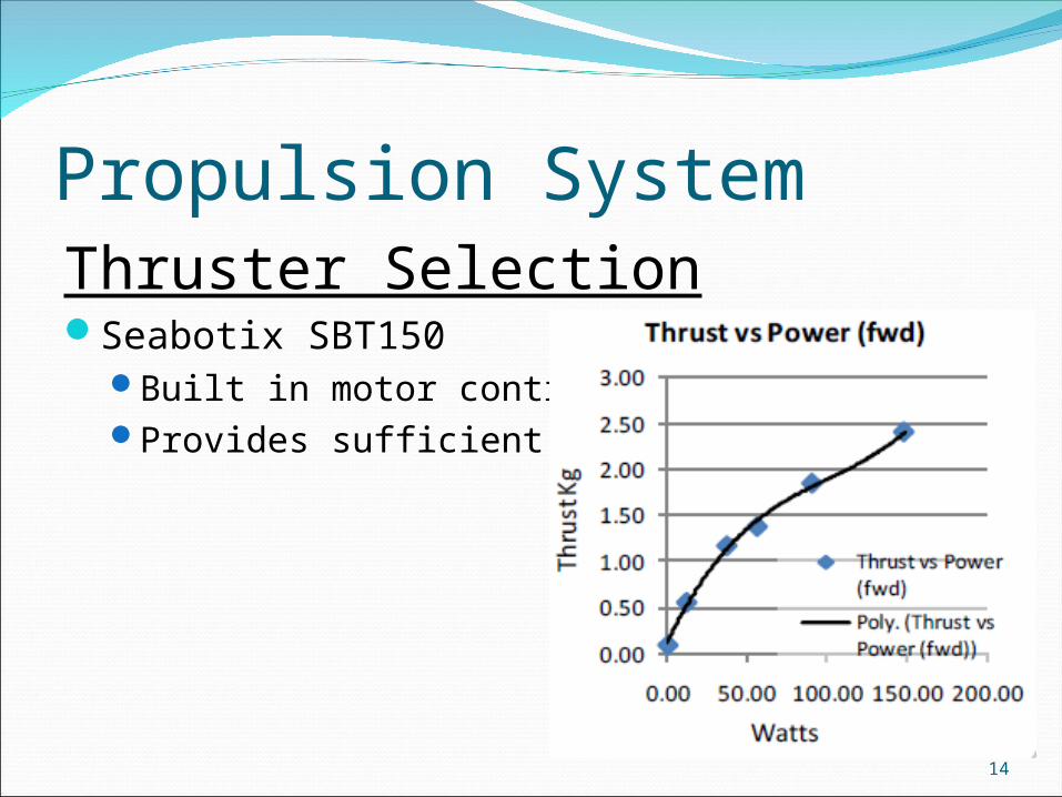
Propulsion System Thruster SelectionSeabotix SBT150
Built in motor controllers Provides sufficient thrust
14

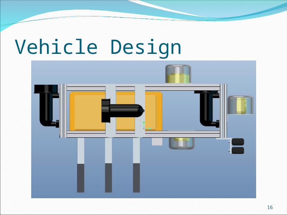
Vehicle Design Hull
Pelican box Water tight and large enough to house all electrical components
FrameMust support and house all
components8020 (T-frame) Aluminum
Easily adjustable Minimize cost
15
Vehicle Design
16

Vehicle Design
17

Competition ComponentsMarker Dropper
Use two magnets (permanent/electromagnet) Permanent magnet holds steel sphere Electromagnet cancels magnetic field Drop metallic sphere
Mechanical GrabberUsed to hoist a rescue object
Design process not complete Scoop Array of claws 3 prong grabber
18

Competition Components
19
Sensors Camera
Shape RecognitionColor RecognitionWebcam
Charge Coupled Device (CCD) Excellent low light performance
HousingInertial Measurement Unit
Stability control Data will be input into the microcontroller for data analysis
20
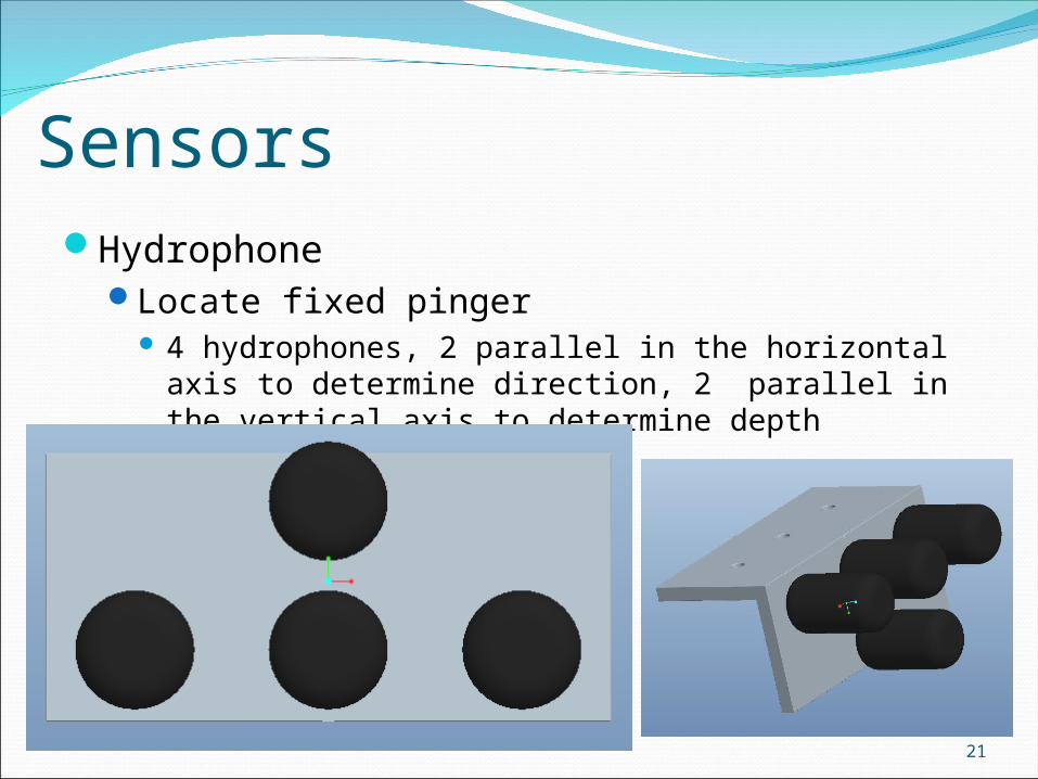
Sensors Hydrophone
Locate fixed pinger 4 hydrophones, 2 parallel in the horizontal axis to determine
direction, 2 parallel in the vertical axis to determine depth
21
22
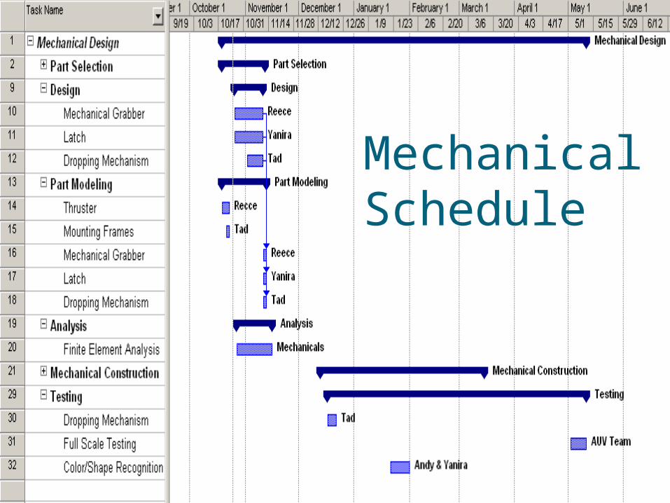
Mechanical Schedule
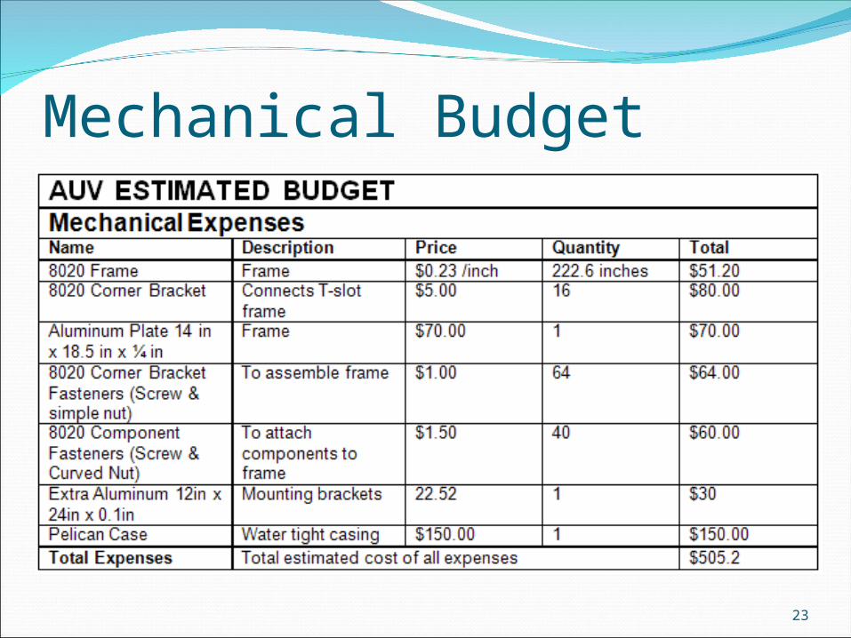
Mechanical Budget
23

Power and ElectronicsSupply sufficient power
electronics, sensors, additional components and four thrusters
Identifying power requiredThrusters have been chosenElectronics and sensors have to be finalizedAdditional components have to be finalized
2011 rules have not been released
24

Power and Electronics Battery SelectionThrusters
Use two LiFePO4 batteries in seriesThrusters will be connected in parallelThrusters can run for over one hour continuouslyMax current drawn by the entire circuit will be 21.2 Amps
with Voltage of 28.1 VMicrocontroller,Webcam,Hydrophones
5V, 5A battery using voltage/current regulators
25

Top-Level Design
26

Electrical Schedule
27

Electrical Budget
28

Risk AssessmentBudget Miscalculations
If budget is incorrectly estimated the treasurer is required to reevaluate all expenditures. reopen the parts/materials search process with the team and
find cheaper parts to reduce expenses. required to begin searching for new sponsors in an attempt to
raise more money.
29
Risk Assessment Critical Scheduling Issues
If production is vastly behind schedule the project manager is tasked with evaluating team performance Every team member is required to work extra hours on weekends Sections of the design that are not critical may be eliminated
Evaluate design to determine what to pursue and abandon
30

Risk Assessment Malfunctioning Parts
RepairWarranty
If the warranty holds the malfunctioning part will be returned in exchange for a working part
If the budget allows, one spare part will be ordered for the important items when they are purchased Otherwise money will have to be raised to purchase replacement
parts
31

Risk AssessmentLoss of Team Member
Sick, injured, or has departedSplit additional work among the teamThe team member will be kept ‘in the know’ so that upon
their return the team member can get back to workIf the team member is unable to return the team will divide
their part and ‘keep the ball rolling’
32
Risk Assessment Requirements/Specifications Not Met
Adjustment current designReevaluate what can be accomplishedAbandon components that are not required to qualify for
the competitionThe team will have to adjust their goals and try to deliver a
finished productThe team will also lay the groundwork for the next team in
meeting all requirements and specifications for the next competition
33

Risk AssessmentTechnological IssuesSensors
Not communicating with the microcontroller correctly Reevaluate wired connections and programming
Seek faculty assistanceExclude specific function until further notice
Microcontroller Review specific software resulting in malfunctionRewrite and reintegrate software into main programRewrite entire program
34

Risk AssessmentTechnological IssuesElectronics
All electronic equipment, connections and wires will be reviewed
Any faulty equipment will be discarded and replaced
The team will be required to provide extensive documentation as to why problems occurred and what can be done to prevent this problem for the next team working on the AUV
35
DeliverablesHardwareReports
Project proposalDetailed design and test reviewLaboratory notebookWeekly meeting minutesAUVSI journal paperSchematic
36
Referenceshttp://www.auvsifoundation.org/AUVSI/
FOUNDATION/UploadedImages/AUV_Mission_Final_2010.pdf
Team 4 Final Proposal
BeagleBoard User Manual
37