Mil Std 100e Notice 2
58
MIL-STD-100E NOTICE 2 4 SEPTEMBER 1992 MILITARY STANDARD ENGINEERING DRAWING PRACTICES TO ALL HOLDERS OF MIL-STD-100E: 1. Make the following pen and ink changes: a. Page xv, paragraph 606. Change title to “Reinstating a superseded (old drawing, differen number) drawing.” b. Page xix, Appendix E, paragraph 40.4. Change to “Abbreviated distribution statements and export control warning notices.” c. Page 16, paragraphs 3.9,3.9.1,3.9.2, and 3.9.3. Delete all four definitions. d. Page 17, paragraph 3.4, lines 3, 6 and 7. Change “CAGE code” to “CAGE: Code”. e. Page 18, paragraphs 3.16 and 3.17. Delete both definitions. f. Page 22, paragraph 3.44, line 2. Change “CAGE code” to “CAGE Code”. g. Page 24, paragraph 3.59, line 3. Change “CAGE code”’ to “CAGE Code”. h. Page 26, paragraph 3.70, line 2. Change “repairable” to “repair-able” and “MIL-STD-1388/1“ to “MIL-STD-1388-1“. i. Page 34, paragraph 6.4. Delete “Baseline” and changr “CAGE code” to “CAGE code”. j. Page 100-1, ” paragraph 101.1.1, line 3. Change the phrase “a component of a largcr unit” to “an element of a larger item. ” k. Page 400-8,” NOTE 1. Change “dash numbers” to “suffix identifiers”. 1. Page 400-9,” paragraph 406.10, Note 2, first sentence. Change to read “Source control drawing numbers, along with applicable suffixes, establish PINs.” m. Page 400–9, paragraph 406.10, NOTE 2. In line 3 delete “identified and”, and in line 4 change “dash number” to “suffix identifier”. AMSC N/A DRPR DISTRIBUTION STATEMENT A. Approved for public release; distribution in unlimited. Downloaded from http://www.everyspec.com
-
Upload
logonwheeler -
Category
Documents
-
view
43 -
download
1
description
Mil Std 100e Notice 2
Transcript of Mil Std 100e Notice 2

MIL-STD-100ENOTICE 24 SEPTEMBER 1992
MILITARY STANDARD
ENGINEERING DRAWING PRACTICES
TO ALL HOLDERS OF MIL-STD-100E:
1. Make the following pen and ink changes:
a. Page xv, paragraph 606. Change title to “Reinstating a superseded (old drawing,differen number) drawing.”
b. Page xix, Appendix E, paragraph 40.4. Change to “Abbreviated distributionstatements and export control warning notices.”
c. Page 16, paragraphs 3.9,3.9.1,3.9.2, and 3.9.3. Delete all four definitions.
d. Page 17, paragraph 3.4, lines 3, 6 and 7. Change “CAGE code” to “CAGE: Code”.
e. Page 18, paragraphs 3.16 and 3.17. Delete both definitions.
f. Page 22, paragraph 3.44, line 2. Change “CAGE code” to “CAGE Code”.
g. Page 24, paragraph 3.59, line 3. Change “CAGE code”’ to “CAGE Code”.
h. Page 26, paragraph 3.70, line 2. Change “repairable” to “repair-able” and“MIL-STD-1388/1“ to “MIL-STD-1388-1“.
i. Page 34, paragraph 6.4. Delete “Baseline” and changr “CAGE code” to “CAGEcode”.
j. Page 100-1, ” paragraph 101.1.1, line 3. Change the phrase “a component of a largcrunit” to “an element of a larger item. ”
k. Page 400-8,” NOTE 1. Change “dash numbers” to “suffix identifiers”.
1. Page 400-9,” paragraph 406.10, Note 2, first sentence. Change to read “Source controldrawing numbers, along with applicable suffixes, establish PINs.”
m. Page 400–9, paragraph 406.10, NOTE 2. In line 3 delete “identified and”, and in line4 change “dash number” to “suffix identifier”.
AMSC N/A DRPRDISTRIBUTION STATEMENT A. Approved for public release; distribution in unlimited.
Downloaded from http://www.everyspec.com

MIL-STD-100ENOTICE 2
n. Page 400-10, paragraph 406.11.1, line 6, Change “dash numbers” to “suffixidentifiers”.
o. Page 500-8.” Delete Figure 500-2,”
p. Page 500-9.” Delete Figure 500-3,”
q. Page 600-3,” title of Figure 600.1. ” Change “Revision block” to “Revisitions block”.
r. Page 600-4,” paragraph 602.6, line 3. Change “revisition block” to “revisions block”.
s. Page 600-4,” title of Figure 600-2.” Change “Revisition block” to “Revisions block”.
t. Page 600-9,” paragraph 605.1. In line 6. change notations” to “history”, and in line 8change “revision block” to “revisitions block”.
u. Page 700-8.” paragraph 709, line 2. Change “Revision Block” to “revisions block”.
V. Page B-8, paragraph 40.1.8. In line 2 change “deleting” to “removing”, and in line 5change “revision block” to “revisions block”.
W. Page B–8, Figure B-7. Delete from Figure the notation “OLD CLASSIFICATIONMAY BE LINED OUT OR REMOVED.”
x. Page D-3, paragraph 40.5.1, line 1. Change to read: “Existing single-source, sourcecontrol drawings shall...”
y. Page D-9, paragraph 50.3.2, last sentence. Change to read: Each item of data andeach sheet that contains data to be protected is to marked with above statement.
2
Downloaded from http://www.everyspec.com
MIL-STD-100ENOTICE 2
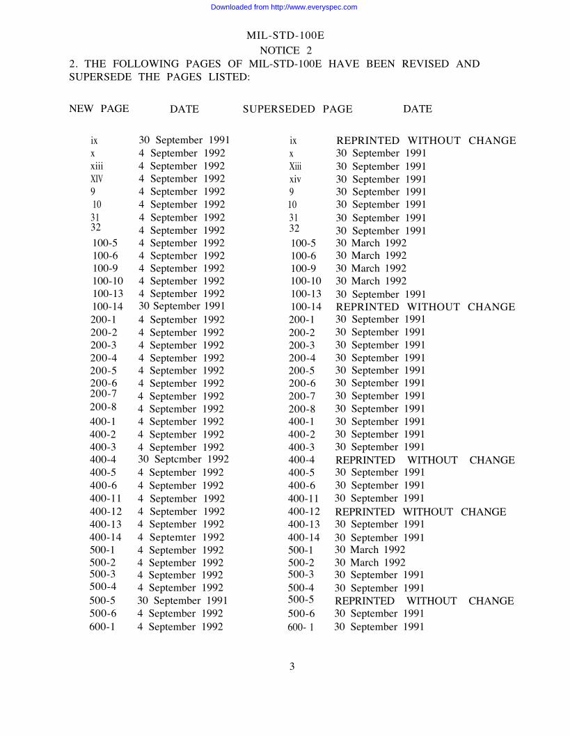
2. THE FOLLOWING PAGES OF MIL-STD-100E HAVE BEEN REVISED ANDSUPERSEDE THE PAGES LISTED:
NEW PAGE DATE
ixxxiiiXIV9103132100-5100-6100-9100-10100-13100-14200-1200-2200-3200-4200-5200-6200-7200-8400-1400-2400-3400-4400-5400-6400-11400-12400-13400-14500-1500-2500-3500-4500-5500-6600-1
30 September 19914 September 19924 September 19924 September 19924 September 19924 September 19924 September 19924 September 19924 September 19924 September 19924 September 19924 September 19924 September 199230 September 19914 September 19924 September 19924 September 19924 September 19924 September 19924 September 19924 September 19924 September 19924 September 19924 September 19924 September 199230 Septcmber 19924 September 19924 September 19924 September 19924 September 19924 September 19924 Septemter 19924 September 19924 September 19924 September 19924 September 199230 September 19914 September 19924 September 1992
SUPERSEDED PAGE DATE
ixxXiiixiv9103132100-5100-6100-9100-10100-13100-14200-1200-2200-3200-4200-5200-6200-7200-8400-1400-2400-3400-4400-5400-6400-11400-12400-13400-14500-1500-2500-3500-4500-5500-6600- 1
REPRINTED WITHOUT CHANGE30 September 199130 September 199130 September 199130 September 199130 September 199130 September 199130 September 199130 March 199230 March 199230 March 199230 March 199230 September 1991REPRINTED WITHOUT CHANGE30 September 199130 September 199130 September 199130 September 199130 September 199130 September 199130 September 199130 September 199130 September 199130 September 199130 September 1991REPRINTED WITHOUT CHANGE30 September 199130 September 199130 September 1991REPRINTED WITHOUT CHANGE 30 September 199130 September 199130 March 199230 March 199230 September 199130 September 1991REPRINTED WITHOUT CHANGE30 September 199130 September 1991
3
Downloaded from http://www.everyspec.com

MIL-STD-100ENOTICE 2
600-2600-5600-6600-7600-8600-11600-12600-13600-14700-5700-6B-5B-6E-1E-2
4 September 19924 September 19924 September 19924 September 19924 September 19924 September 19924 September 19924 September 199230 September 19914 September 19924 September 19924 September 199230 September 19914 September 19924 September 1992
600-2600-5600-6600-7600-8600-11600-12600-13600-14700-5700-6B-5B-6E-1E-2
30 March 199230 September 199130 September 199130 September 199130 September 199130 September 199130 September 199130 September 1991REPRINTED WITHOUT CHANGE30 September 199130 September 199130 March 1992REPRINTED WITHOUT CHANGE30 September 199130 September 1991
3. RETAIN THIS NOTICE AND INSERT BEFORE TABLE OF CONTENTS
4. Holders of MIL–STD–100E will verify that page changes indicated above have beenentered. This notice will be retained as a check sheet. This issuance, together with appendedpages, is a separate publication. Each notice is to be retained by stocking points until theMilitary Standard is completely revised or cancelled.
5. Vertical lines are used in this Notice to denote changes (additions, modifications,corrections, deletions) from the basic standard. This was done as a convenience only and the -
Government assumes no liability whatsoever for any inaccuracies in these notations. Biddersand contractor-s are cautioned to evaluate the requirements of this document based on theentire content irrespective of the marginal notations and relationship to the basic standard.
Custodians: Preparing activity:
Army - AR Army - ARNavy - SAAir Force -16 (Project DRPR-0328)
Review activities:Army - AT, AV CE, CR, EA, ER, MI, SC, SM, TENavy - AS, CH, EC, MC, OS, SH, TD, YDAir Force -11, 13, 14, 18, 19, 19, 79, 90, 99DLA - CS, DH, ES, GS, ISNSA - NS
User activities:Army - GL, MEAir Force -68, 70, 71, 80, 84
4
Downloaded from http://www.everyspec.com
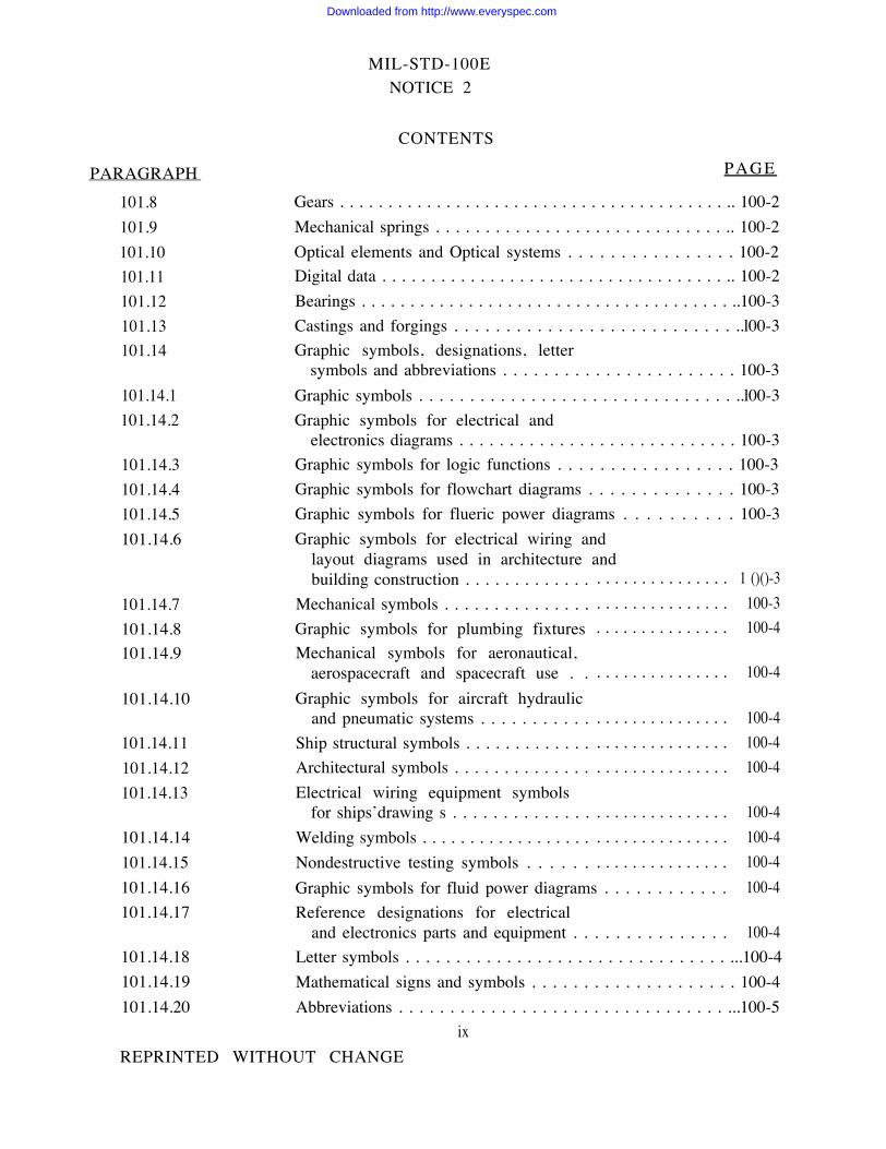
PARAGRAPH
101.8101.9101.10101.11101.12101.13101.14
101.14.1101.14.2
101.14.3101.14.4101.14.5101.14.6
PAGE
101.14.7101.14.8101.14.9
101.14.10
101.14.11101.14.12101.14.13
101.14.14101.14.15101.14.16101.14.17
101.14.18101.14.19101.14.20
MIL-STD-100ENOTICE 2
CONTENTS
Gears . . . . . . . . . . . . . . . . . . . . . . . . . . . . . . . . . . . . . . . . .. 100-2Mechanical springs . . . . . . . . . . . . . . . . . . . . . . . . . . . . . .. 100-2Optical elements and Optical systems . . . . . . . . . . . . . . . . 100-2Digital data . . . . . . . . . . . . . . . . . . . . . . . . . . . . . . . . . . . .. 100-2Bearings . . . . . . . . . . . . . . . . . . . . . . . . . . . . . . . . . . . . . . ..100-3Castings and forgings . . . . . . . . . . . . . . . . . . . . . . . . . . . ..l00-3Graphic symbols, designations, letter
symbols and abbreviations . . . . . . . . . . . . . . . . . . . . . . . 100-3Graphic symbols . . . . . . . . . . . . . . . . . . . . . . . . . . . . . . . ..l00-3Graphic symbols for electrical and
electronics diagrams . . . . . . . . . . . . . . . . . . . . . . . . . . . . 100-3Graphic symbols for logic functions . . . . . . . . . . . . . . . . . 100-3Graphic symbols for flowchart diagrams . . . . . . . . . . . . . . 100-3Graphic symbols for flueric power diagrams . . . . . . . . . . 100-3Graphic symbols for electrical wiring and
layout diagrams used in architecture andbuilding construction . . . . . . . . . . . . .
Mechanical symbols . . . . . . . . . . . . . . .Graphic symbols for plumbing fixturesMechanical symbols for aeronautical,
aerospacecraft and spacecraft use . .Graphic symbols for aircraft hydraulic
and pneumatic systems . . . . . . . . . . .Ship structural symbols . . . . . . . . . . . . .Architectural symbols . . . . . . . . . . . . . .Electrical wiring equipment symbols
for ships’drawing s . . . . . . . . . . . . . .Welding symbols . . . . . . . . . . . . . . . . . .Nondestructive testing symbols . . . . . .
. . . . . . . . . . . . . . . 1 ()()-3
. . . . . . . . . . . . . . .
. . . . . . . . . . . . . . .
. . . . . . . . . . . . . . .
. . . . . . . . . . . . . . .
. . . . . . . . . . . . . . .
. . . . . . . . . . . . . . .
. . . . . . . . . . . . . . .
. . . . . . . . . . . . . . .
. . . . . . . . . . . . . . .Graphic symbols for fluid power diagrams . . . . . . . . . . . .Reference designations for electrical
and electronics parts and equipment . . . . . . . . . . . . . . .
100-3100-4
100-4
100-4100-4100-4
100-4100-4100-4100-4
100-4Letter symbols . . . . . . . . . . . . . . . . . . . . . . . . . . . . . . . . ...100-4Mathematical signs and symbols . . . . . . . . . . . . . . . . . . . . 100-4Abbreviations . . . . . . . . . . . . . . . . . . . . . . . . . . . . . . . . ...100-5
ixREPRINTED WITHOUT CHANGE
Downloaded from http://www.everyspec.com

MIL-STD-100ENOTICE 2
PARAGRAPH101.15101.15.1101.15.1.1101.15.2101.15.3101.16101.16.1101.16.1.1101.16.1.2101.16.1.3101.16.1.4101.16.1.5101.16.1.6101.16.1.6.1101.16.1.6.2101.16.1.7101.16.2101.16.2.1101.16.2.2101.16.2.3101.17101.17.1101.17.2101.17 .2.1101.17.3101.18101.18.1101.18.1.1101.18.1.2101.18.1.3101.18.1.4101.l8.1.5101.19101.20
CONTENTS
PAGEDiagrams . . . . . . . . . . . . . . . . . . . . . . . . . . . . . . . . . . . ...100-5Electrical and electronics diagrams . . . . . . . . . . . . . . . . . . 100-5Logic circuit diagrams . . . . . . . . . . . . . . . . . . . . . . . . . ...100-5Printed wiring drawings . . . . . . . . . . . . . . . . . . . . . . . . ...100-5Printed board description in digital form . . . . . . . . . . . . . 100-5Media for drawings and associated lists . . . . . . . . . . . . . . 100-5Materials . . . . . . . . . . . . . . . . . . . . . . . . . . . . . . . . . . . . . . . . . . . . ....100-5Plastic sheet or roll . . . . . . . . . . . . . . . . . . . . . . . . . . . . ...100-5Paper, tracing . . . . . . . . . . . . . . . . . . . . . . . . . . . . . . . . ...100-5Film, Diazotype . . . . . . . . . . . . . . . . . . . . . . . . . . . . . . . ..100-5Paper, Diazotype . . . . . . . . . . . . . . . . . . . . . . . . . . . . . ...100-5Preparation of duplicate original . . . . . . . . . . . . . . . . . . . . 100-6Digital data . . . . . . . . . . . . . . . . . . . . . . . . . . . . . . . . . . . ..100-6Plotters . . . . . . . . . . . . . . . . . . . . . . . . . . . . . . . . . . . . . . . . 100-6Maintenancc . . . . . . . . . . . . . . . . . . . . . . . . . . . . . . . . . . . . 100-6Associated lists, materials . . . . . . . . . . . . . . . . . . . . . . . . . 100-6Digital product definition data . . . . . . . . . . . . . . . . . . . . . 100-6Media . . . . . . . . . . . . . . . . . . . . . . . . . . . . . . . . . . . . . . . . . . . . . . .100-6Initial Graphics Exchange Specification(iges) . . . . . . . 100-6Raster engineering drawing data files . . . . . . . . . . . . . . . . 100-6Scale . . . . . . . . . . . . . . . . . . . . . . . . . . . . . . . . . . . . . . . ...100-6Selection of scale..... . . . . . . . . . . . . . . . . . . . . . . . ...100-6Indication of scale . . . . . . . . . . . . . . . . . . . . . . . . . . . . . . ..100-7Fractional method . . . . . . . . . . . . . . . . . . . . . . . . . . . . . ...100-7Drawing not to scale. . . . . . . . . . . . . . . . . . . . . . . . . . ...100-7Drawing marking for item identification . . . . . . . . . . . . . . 100-7Drawing requirements for part identification marking . . 100-7Identification marking location and size . . . . . . . . . . . . . . 100-7Tags and plates . . . . . . . . . . . . . . . . . . . . . . . . . . . . . . . ...100-8Packaged items . . . . . . . . . . . . . . . . . . . . . . . . . . . . . . . ...100-8Altered or selected item identification . . . . . . . . . . . . . . . 100-8Printed wirirn assemblies . . . . . . . . . . . . . . . . . . . . . . . . . . 100-8Optional/alternative designs . . . . . . . . . . . . . . . . . . . . . . . 100-8Depietion of castings and forgings . . . . . . . . . . . . . . . . . . . 100-8
xSuperedes page x of 30 September 1991
Downloaded from http://www.everyspec.com

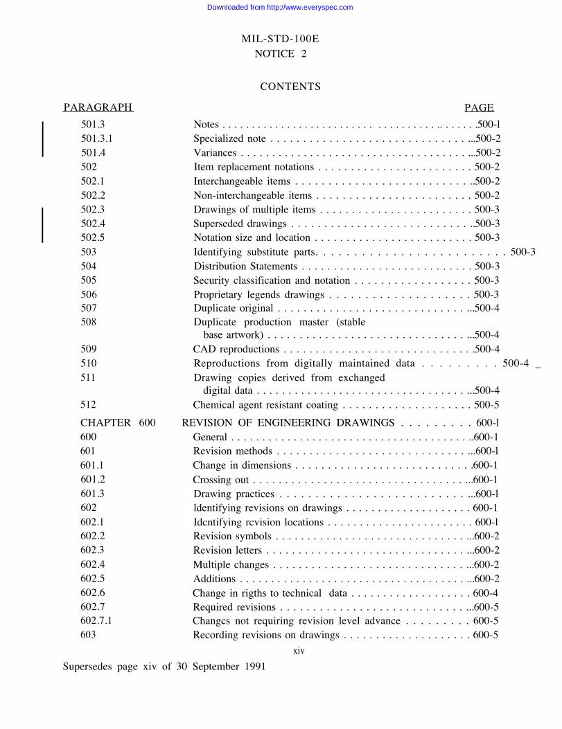
PARAGRAPH405406406.1406.2406.3406.4406.5406.6406.7406.8406.9
406.9.1406.10406.10.1406.11406.11.1406.11.2406.12406.12.1406.12.2406.12.3406.13406.13.1406.14406.15
406.15.1406.15.2406.15.3406.15.4406.15.4.1
CHAPTER 500500501501.1501.2
MIL-STD-10OENOTICE 2
CONTENTS
Supersedes page xiii of 30
PAGEFind number . . . . . . . . . . . . . . . . . . . . . . . . . . . . . . . . . . . . . . . . 400-2Identification requirements . . . . . . . . . . . . . . . . . . . . . . . . 400-2New drawings and associated lists . . . . . . . . . . . . . . . . . . . 400-2Existing drawings and associated lists . . . . . . . . . . . . . . . . 400-3Referenced documents . . . . . . . . . . . . . . . . . . . . . . . . . ...400-3CAGE Code . . . . . . . . . . . . . . . . . . . . . . . . . . . . . . . . . ...400-3Drawing number structure . . . . . . . . . . . . . . . . . . . . . ...400-3PIN length and application . . . . . . . . . . . . . . . . . . . . . ...400-5Records . . . . . . . . . . . . . . . . . . . . . . . . . . . . . . . . . . . . . ...400-6Associated lists . . . . . . . . . . . . . . . . . . . . . . . . . . . . . . . ...400-6Transferring design responsibility to
another activity . . . . . . . . . . . . . . . . . . . . . . . . . . . . . ...400-6Maintaining design activity identities . . . . . . . . . . . . . . . . 400-8Item identification and PIN . . . . . . . . . . . . . . . . . . . . . . . . 400-8Identification cross reference . . . . . . . . . . . . . . . . . . . . . . . 400-9ldentification on drawings . . . . . . . . . . . . . . . . . . . . . . . . . 400-9Vendor item and source control drawings . . . . . . . . . . . . . 400-10CAGE Code and part numbering . . . . . . . . . . . . . . . . . . . 400-l0Numbering of related parts . . . . . . . . . . . . . . . . . . . . . ...400-11Matched part designation . . . . . . . . . . . . . . . . . . . . . . . ...400-11Symmetrically opposite (mirrored) parts . . . . . . . . . . . . . . 400-11Inseparable assembly . . . . . . . . . . . . . . . . . . . . . . . . . . ...400-11Change requiring new identification . . . . . . . . . . . . . . . . . 400-11Computer program . . . . . . . . . . . . . . . . . . . . . . . . . . . . ...400-12Changes not requiring new identification . . . . . . . . . . . . . 400-12Identification of materials, processes
and protective treat merit... . . . . . . . . . . . . . . . . . . . . . . 400-13Group identification . . . . . . . . . . . . . . . . . . . . . . . . . . . ...400-13Other identification . . . . . . . . . . . . . . . . . . . . . . . . . . . . . .400-13Formulation identification . . . . . . . . . . . . . . . . . . . . . . . . . 400-13Bulk materials identification . . . . . . . . . . . . . . . . . . . . . . . 400-14Drawings for bulk materials . . . . . . . . . . . . . . . . . . . . . . . . 400-14
MARKINGS ON ENGINEERING DRAWINGS . . . . . . . . 500-1General . . . . . . . . . . . . . . . . . . . . . . . . . . . . . . . . . . . . . . . . . . . . .500-lSpecial Items and processes . . . . . . . . . . . . . . . . . . . . . . . . . . . . . . . 500-lMarking for special items and processes . . . . . . . . . . . . . . 500-lFeature identification . . . . . . . . . . . . . . . . . . . . . . . . . . . . . . . ..500-l
xiiiSeptember 1991
Downloaded from http://www.everyspec.com
MIL-STD-100ENOTICE 2
PARAGRAPH501.3501.3.1501.4502502.1502.2502.3502.4502.5503504505506507508
509510511
512
CHAPTER 600600601601.1601.2601.3602602.1602.2602.3602.4602.5602.6602.7602.7.1603
CONTENTS
PAGENotes . . . . . . . . . . . . . . . . . . . . . . . . . . . . . . . . . . . . .. . . . . . .500-lSpecialized note . . . . . . . . . . . . . . . . . . . . . . . . . . . . . . ...500-2Variances . . . . . . . . . . . . . . . . . . . . . . . . . . . . . . . . . . . . ...500-2Item replacement notations . . . . . . . . . . . . . . . . . . . . . . . . 500-2Interchangeable items . . . . . . . . . . . . . . . . . . . . . . . . . . ..500-2Non-interchangeable items . . . . . . . . . . . . . . . . . . . . . . . . 500-2Drawings of multiple items . . . . . . . . . . . . . . . . . . . . . . . . 500-3Superseded drawings . . . . . . . . . . . . . . . . . . . . . . . . . . . ..500-3Notation size and location . . . . . . . . . . . . . . . . . . . . . . . . . 500-3Identifying substitute parts. . . . . . . . . . . . . . . . . . . . . . . . . 500-3Distribution Statements . . . . . . . . . . . . . . . . . . . . . . . . . . . 500-3Security classification and notation . . . . . . . . . . . . . . . . . . 500-3Proprietary legends drawings . . . . . . . . . . . . . . . . . . . . 500-3Duplicate original . . . . . . . . . . . . . . . . . . . . . . . . . . . . . ...500-4Duplicate production master (stable
base artwork) . . . . . . . . . . . . . . . . . . . . . . . . . . . . . . . ...500-4CAD reproductions . . . . . . . . . . . . . . . . . . . . . . . . . . . . . .500-4Reproductions from digitally maintained data . . . . . . . . . 500-4 _Drawing copies derived from exchanged
digital data . . . . . . . . . . . . . . . . . . . . . . . . . . . . . . . . . ...500-4Chemical agent resistant coating . . . . . . . . . . . . . . . . . . . . 500-5
REVISION OF ENGINEERING DRAWINGS . . . . . . . . . 600-lGeneral . . . . . . . . . . . . . . . . . . . . . . . . . . . . . . . . . . . . . . ..600-1Revision methods . . . . . . . . . . . . . . . . . . . . . . . . . . . . . ...600-lChange in dimensions . . . . . . . . . . . . . . . . . . . . . . . . . . . .600-1Crossing out . . . . . . . . . . . . . . . . . . . . . . . . . . . . . . . . . ...600-1Drawing practices . . . . . . . . . . . . . . . . . . . . . . . . . . ...600-lldentifying revisions on drawings . . . . . . . . . . . . . . . . . . . . 600-1Idcntifying rcvision locations . . . . . . . . . . . . . . . . . . . . . . . 600-lRevision symbols . . . . . . . . . . . . . . . . . . . . . . . . . . . . . . ...600-2Revision letters . . . . . . . . . . . . . . . . . . . . . . . . . . . . . . . ...600-2Multiple changes . . . . . . . . . . . . . . . . . . . . . . . . . . . . . . ...600-2Additions . . . . . . . . . . . . . . . . . . . . . . . . . . . . . . . . . . . . ...600-2Change in rigths to technical data . . . . . . . . . . . . . . . . . . . 600-4Required revisions . . . . . . . . . . . . . . . . . . . . . . . . . . . . ...600-5Changcs not requiring revision level advance . . . . . . . . . 600-5Recording revisions on drawings . . . . . . . . . . . . . . . . . . . . 600-5
xivSupersedes page xiv of 30 September 1991
Downloaded from http://www.everyspec.com

ANSI Y14.36
ANSI Y32.4
ANSI Y32.9
MIL-STD-100ENOTICE 2
Surface Texture Symbols
Graphic Symbols for PlumbingFixtures for Diagrams Used inArchitecture and BuildingConstruction
Graphic Symbols for Electric Wiringand Layout Diagrams Used inArchitectural and BuildingConstruction
ANSI Y32.10 Graphic Symbols for Fluid PowerDiagrams
AMERICAN SOCIETY FOR TESTING AND MATERIALS (ASTM)
ASTM E380 Standtad for Metric Practice
AMERICAN WELDING SOCIETY (AWS)
ANSI/AWS A2.4 Symbols for Welding andNondestructive Testing
ANSI/AWS A3.0 Welding Terms and Definitions
INSTITUTE OF ELECTRICAL. AND ELECTRONIC ENGINEERS (IEEE)
ANSI/IEEE Std 91 Graphic Symbols for Logic Functions
ANSI/IEEE Std 91a Supplement to Graphic Symbols for Logic Functions
ANSI/IEEE Std 200 Reference Designations forElectrical and Electronic Parts andEquipment
ANSI/IEEE Std 260
ANSI/IEEE Std 280
Letter Symbols for Units ofMeasurement (SI Units, Customaryinch-Pound Units and Certain OtherUnits)
letter Symbols for Quantities usedin Electrical Science and ElectricalEngineering (Same as ANSI Y10.5-1985)
9
Supersedes page 9 of 30 September 1991
Downloaded from http://www.everyspec.com
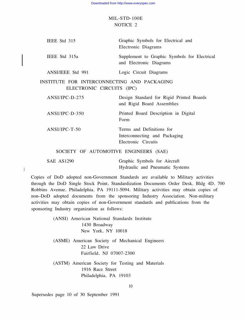
MIL-STD-100ENOTICE 2
I
IEEE Std 315 Graphic Symbols for Electrical andElectronic Diagrams
IEEE Std 315a Supplement to Graphic Symbols for Electricaland Electronic Diagrams
ANSI/IEEE Std 991 Logic Circuit Diagrams
INSTITUTE FOR INTERCONNECTING AND PACKAGINGELECTRONIC CIRCUITS (IPC)
ANSI/IPC-D-275 Design Standard for Rigid Printed Boardsand Rigid Board Assemblies
ANSI/IPC-D-350 Printed Board Description in DigitalForm
ANSI/IPC-T-50 Terms and Definitions forInterconnecting and PackagingElectronic Circuits
SOCIETY OF AUTOMOTIVE ENGINEERS (SAE)
SAE AS1290 Graphic Symbols for AircraftHydraulic and Pneumatic Systems
Copies of DoD adopted non-Government Standards are available to Military activitiesthrough the DoD Single Stock Point, Standardization Documents Order Desk, Bldg 4D, 700Robbins Avenue, Philadelphia, PA 19111-5094. Military activities may obtain copies ofnon–DoD adopted documents from the sponsoring Industry Association. Non-militaryactivities may obtain copies of non-Government standards and publications from thesponsoring Industry organization as follows:
(ANSI) American National Standards Institute1430 BroadwayNew York, NY 10018
(ASME) American Society of Mechanical Engineers22 Law DriveFairfield, NJ 07007-2300
(ASTM) American Society for Testing and Materials1916 Race StreetPhiladelphia, PA 19103
10
Supersedes page 10 of 30 September 1991
Downloaded from http://www.everyspec.com

MILSTD-100ENOTICE 2
6. NOTES
(This section contains information of a general or explanatory nature that may be helpful, butis not mandatory.)
6.1 Intended use. The requirements contained herein apply to hardcopy drawings, digitaldata file(s), associated lists and textual data resulting from the contractual application ofDOD-D- 1()()(), MIL-T-31000 or MIL-T-47500.
6.1.1 Applicabilitypacktage element isdesign.
I
The current document specifying engineering drawings as a technical dataMIL–T-31000. DOD–D–1000 and MIL–T–47500 are inactive
6.2 Acqu isition requirements.
6.2.1 Issue of DODISS. When this standard is used in acquisition, the applicable issue of theDODISS must be cited in the solicitatition (see 2.1.1, and 2.2).
for new
6.2.2 Tailoring guidance. To ensure proper application of this Standard, invitations for bids,requests for proposals, and Contract Data Requirements Lists (CDRLs) must tailor therequirements in Chapters 100 through 700” to exclude unnecessary requirements. It isessential (hat the contractual applicability of the numerous referenced documents, ascontained herein. especially Chapter 100, be as definitive as practicable. Although themanner and extent of such tailtoring will vary in accordance with program or end–itemrequirements, the following is provided as a minimum for consideration in acquisitiondocuments:
A. Media (See 101.16 and 704 including NOTE)
(1) Hard Copy: originals reproductions
(2) Digital Data: magnetic tape, IGES (type) tramsmission
B. Drawing Format (See ANSI Y 14.1)
(1) Contractor
(2) Government
31
Supersedes page 31 of 30 September 1991
Downloaded from http://www.everyspec.com

MIL-STD-100ENOTICE 2
C. Application Data (See 101.1.1)
(1) Whether required(2) On drawing(3) Separate document(4) Used on identity
D. Drawing Detail (See ASME Y14.24M)
(1) Monodetail(2) Multidetail
E. Metric (See 101.4)
F. ANSI Y14.5M (Version) (See 101.21.6e)
G. Drawing Notes (See 101.21.5)
(1) On drawing(2) Separate document
H. Quality Assurance Provisions - Location and Format (See l0l.21.6h)
I.
J.
K.
L.
M
N.
o .
Types of Drawings (See ASME Y14.24M and Chapter 200)”
Multi-Sheet Drawings (Revisions) (See 604)
Redrawn Drawings (Practices) (See 605)
Special Items and Processes (See 501 )
Associated Lists: Parts Lists, Data Lists, Index Lists (See Chapter 700)
(1)(2)
(3)
Manually preparedDerived from digital dataPLs: Separate, integral or contractors option
Distribution Statements and Export Control Notices (See 504, 602.7 and Appendix E).
Software Master Media (See 204.2.6.1)
6.3 International agreements. Certain provisions of this Military Standard are the subject ofInternational Standardization Agreements (see following listing). When revision orcancellation of this standard is proposed which will affect or violate the InternationalAgreement concerned, the Preparing Activity will take appropriate reconciliation actionthrough international standardization channels including departmental standardization offices,if required.
32Supersedes page 32 of 30 September 1991
Downloaded from http://www.everyspec.com
MIL-STD-100ENOTICE 2
101.14,20” Abbreviations. Abbreviations shall be in accordance with MIL-STD-12.
101.15 Diagrams.
101.15.1 Electrical and electronics diagrams. Electrical and electronics diagrams andinterconnection diagrams shall be in accordancedance with ANSI Y14.15, Y14.15a and Y14.15b.
101.15 .1.1 Logic circuit diagrams. Logic circuit diagrams shall be in accordance withANSI/IEEE Std 991.
I 101.15.2 Printed board drawings. Printed board drawings shall be in accordance with therequirements of MIL–STD–275, MIL-STD–2118, ANSI/IPC-T-50, and ANSI/IPC-D-275 asapplicable.
101.15.3 Printed board description in digital form. When printed board descriptions are indigital form (defined either by metric or customary units) the descriptition and form shall be inaccordance with ANSI/IPC-D-350 or MIL-D-28000.
101.16 Media for drawings and associated lists.
101.16.1 Materials.
101.16 .1.1 Plastic sheet or roll. originals on plastic sheet shall be in accordance with
I L-P-519, type I or II, class 2. Undimensioned drawings, printed wiriring artwork masters,production masters, and master pattern drawings shall be in accordance with MIL-D-8510.type 11 (per MIL–STD-275) or L–P–519, type I or II, class 1.
101.16 .1.2 Paper tracing. Tracing paper for dimensioned drawings shall be in accordancewith UU–P–561, Type as specified.
101.16.1.3 Film. Diazotype. Copies on sensitized, diazotype film shall be in accordance withL- F-340, Type and Class as specified.
101016.1.4 Paper, Diazotype. Copies on direct-positive, sensitized (diazotype) paper shall bein accordance with UU–P–221.
100-5
Supersedes page 100-5 of 30 March 1992
Downloaded from http://www.everyspec.com

MIL-STD-100ENOTICE 2
101.16 .1.5 Preparation of duplicate original. Duplicate originals shall not be prepared forthe purpose of maintaining duplicate records. Their application is limited to replacingmissing original drawings.
101.16.1.6 Digital data.
101.16.1.6.1 Plotters. If originals are maintained as digital data, copies resultingelectrostatic plotters need not meet the material, erasure and aging requirementsor UU–P–561.
101.16.1.6.2 Maintenance. Unless otherwise specified. requirements for erasure.paper do not apply to associated lists prepared by automatic data processing, or drawingsprepared and maintained as digital data.
fromof L–P–519
aging and
101.16.1.7 Associated lists, materials. Associated lists prepared from digital data need notmeet the requirements of 101.16.1.1 or 101.16.1.2.
101.16.2 Digital product definition data.
101.16.2. Media. The physical media for delivery of digital product definition data shalconform to MIL–STD-1840.
101.16.2.2 Initial Graphics Exchange Specification (IGES). IGES ergineering data files shall be Class II application data subsets in conformance to MIL-D-28000 and MIL-STD-1840.
101.16.2.3 Raster data files. Rastcr data files shall be in accordance with MIL-R-28002.
100-6
Supersedes pages 100-6 of 30 March 1992
Downloaded from http://www.everyspec.com
MIL-STD-100ENOTICE 2
101.21 Drawing notes. Drawing notes are used to provide information required to clarify therequirements for the item delineated. They may apply to a portion of the drawing or to theentire drawing, providing additional treatment, finish, protection, or other considerations.The notes area of a drawing shall be identified with the heading “NOTES”.
101.21.1 Languagee style. Notes shall be short, concise statements, using the simplest wordsand phrases for conveying the intended meaning. Notes shall not include contractualrequirements such as statements of costs, time and place of delivery, methods of payment,requirements for submission, approval or distribution of data, reports or plans.
101.21.2 Commonly used words and phasees. Certain words and phrases are frequently usedon a drawing. The following rules shall be applied:
a. Reference documents shall be cited as follows:
(1) “...pe”...”
(2) “ ...conforrning to...”
(3) “... as specified in...”
(4) “... in accordance with... ” or “... IAW...”
b. “Unless otherwise specified” shun be used to indicate the generally appliedrequirements. This phrase shall come at the beginning of the note or denoted at the head ofthe NOTES column. This phrase shall be used only when it is possible to clarify its meaningby providing a reference to another document, or requirement on the drawing, that clearlyspecifies the exception(s).
101.21.3 Use of “shall”. “will”. “should” and “may”.
a. “Shall”. “Shall”, the emphatic form of the verb, shall be used whenever arequirement is intended to express a provision that is contractually binding.
b. “Will”. “Will” may be used to express a declaration of purpose on the part ofthe Design Activity. It may be necessary to use “will” in cases when simple futurity isrequired.
c. “Should” and “may”. “Should” and “may” are used when it is necessary toexpress non-mandatory provisions.
100-9
Supersedes page 100-9 of 30 March 1992
Downloaded from http://www.everyspec.com

MIL-STD-100ENOTICE 2
100-10
Downloaded from http://www.everyspec.com
MIL-STD-100ENOTICE 2
I
I
100-13
Supersedes page 100-13 of 30 September 1991
Downloaded from http://www.everyspec.com
MIL-STD-100ENOTICE 2
101.27 Use of Government and non-Government standardization documents. When therequirements in applicable standardization documents do not completely fulfill the designrequirements of the item, engineering drawings may specify the requirements of thestandardization document and the variations necessary to fulfill the design requirements ofthe item, in lieu of preparing new documentation.
101.28 Code Identification, FSCM and CAGE Code. Terms such as “FSCM” or “CodeIdentification” on existing documents or pre-prepared formats in stock need not be updatedto “CAGE Code” or “CAGEC”.
100-14
REPRINTED WITHOUT CHANGE
Downloaded from http://www.everyspec.com

MIL-STD-100ENOTICE 2
200-1
Supersedes page 200-1 of 30 September 1991
Downloaded from http://www.everyspec.com
MIL-STD-100ENOTICE 2
202.2.1 Book-form requirements and limitations. Drawings in book-form shall use A, B, C, and G size sheets, and may include graphic delineations. textual data, tables and tabulations.A, B, and G size sheets may be intermingled in a single drawing. However, C size sheets shallnot be intermingled with other sheet sizes. See 604 for revision procedures. Drawings inbook-form shall not be prepared to circumvent the requirements for furnishing the types ofdrawings normally required for the delineation of an item or system.
202.3 Combination of drawing types. The characteristics of more than one drawing type maybe combined into a single drawing provided that the resulting combination includes the datarequired by the individual drawing types.
202.3.1 Application. Normally several types of engineering drawings and associated lists arerequired to completely define the end–product requirements of an item. As a minimum, acombination of detail and assembly drawings may suffice to define these requirements.However, as the complexity of the item increases, specialized engineering drawings may berequired to provide for full engineering description. As a rule, combinations of detail,assembly, control, installation and diagrammatic drawings will provide the necessaryengineering description. In certain cases, ancillary drawings (see 204.1) may be required formanagement control, logistic purposes, configuration management, manufacturing aids, andother unique functions as might be required by a design or procuring activity.
203. Pictorial drawing. When three dimensional depiction is specified instead of or as asupplement to multiview orthographic drawings, the required pictorial drawing shall be inaccordance with ASME Y14.4M.
200-2
Supersedes page 200-2 of 30 September 1991
Downloaded from http://www.everyspec.com

MIL-STD-100ENOTICE 2
204. Drawing types.
204.1 Industry standard. The following drawing types shall be in accordance with ASMEY14.24M (See Appendix F.)
—
—
—
—
Note
—
—
—
Ancillary drawings
Layout drawing
Detailed drawings:
Assembly drawing
(See Note 1)
monodetail and multidetail
Modifying drawings: altered item and selected item and modification drawings (seea .
Arrangement drawing
Installation drawing
Control drawings: vendor item drawing (formerly specification control drawing), sourcecontrol drawing, interface control drawing, and identification cross reference drawing (seeNotes 4, 5, 6, 7, 8 and 9).
— Mechanical schematic diagram
— Electrical/electronic diagrams: functional block diagram , single line diagram, schematicor circuit diagram, connection or wiring diagram, irterconnection diagram, wiring list, andlogic circuit diagram
— Special application drawings: wiring harness drawing, cablc assembly drawing. printedboard drawing sets - assembly drawing. master drawing, and artwork master, undimensioncddrawing, tube bend drawings – pictorial and tabular delineation. matched set drawing, kitdrawing, and cnt(~ur definition drawing (see Note lo).
NOTE 1: Ancillary drawings are other than end-product drawings used to supplementend–product requirements. Ancillary drawings do not establish item identification. Thesekinds of engineering drawings may be required for management control, logistic purposes,configuration management, manufacturing aids, and other function unique to a designactivity or manufacturer. Drawings of a general nature that describe unique data, processes,methods, heat treatment, protective finishes or special painting, shun be prepared as a generalrequirements drawing in either book-form or other format. See also 202.2.
200-3
Supersedes page 200-3 of 3o September 1991
Downloaded from http://www.everyspec.com

MIL-STD-100ENOTICE 2
200-4
Supersedes page 200-4 of 30 September 1991
Downloaded from http://www.everyspec.com

I
MIL-STD-100ENOTICE 2
NOTE 7: Under certain contracts or purchase orders, Government design or procuringactivity approval may be required for the preparation of Source Control Drawings. SeeAppendix D for Qualification Provisions as applied to Source Control Drawings where theGovernment Activity (Army, Navy, Air Force) is identified by CAGEC and Name in the titleblock or indicated as “CURRENT DESIGN ACTIVITY”.
NOTE 8: A source control drawing provides an engineering description, qualificationrequirements, and acceptance criteria for a vendor item that exclusively provides theperformance. installation, and interchangeability characteristics required for specific criticalapplications. Included on the drawing is a listing of approved sources of supply, theiraddresses, CAGE Code. and item identification for vendor items that have been qualified andapproved for use in a specific application. The source control drawing number and applicablesuffix identifiers establish the PIN. See 406.10, Note 2.
NOTE 9: Unless otherwise specified. the listing of manufacturing sources of supply on asource control drawing by a Government design activity is performed in accordance withAppendix D.
NOTE l0: See also 101.15.2 and 101.15.3 on Printed Board Drawing.
204.2 Government peculiar. The following drawing types (or variations thereof) describeprogram or Government peculiar requirements for drawing types. See also Appendix F.
204.2.1 Inseparable assembly drawing. An inseparable assembly drawing delineates items(pieces) which are separately fabricated and are permanently joined together (as in welded,brazed, riveted, sewed, glued or other processes) to form an integral unit (part) not normallycapable of being disassembled for replacement or repair of the individual pieces. Aninseparable assembly drawing may be prepared in lieu of individual monodetail drawings forinseparable (welded, brazed, bonded, riveted, sewn, glued or other processes) assembliesintended to be procured and replaced us a unit. Example: A welded or riveted bracket, awood, metal or plastic chest, or a canvas case may be covered by an inseparable assemblydrawing without separate detail drawings. See Figure 200-3. (See ASME Y14.24M,Assembly Drawing)
200-5
Supersedes page 200-5 of 30 September 1991
Downloaded from http://www.everyspec.com
MIL-STD-100ENOTICE 2
200-6
Supersedes page 200-6 of 30 September 1991
Downloaded from http://www.everyspec.com
MIL-STD-100ENOTICE 2
200-7
Supersedes page 200-7 of 30 September 1991.
Downloaded from http://www.everyspec.com

MIL-STD-10OENOTICE 2
I
d. QTY: The quantity of each item which is necessary to make up one unit of thepackage.
e. NAME OF ITEM: Nomenclature of each item contained in the package.
f. DWG NO.: The drawing number of each item listed.
g. CAGE CODE: The CAGE Code assigned to the drawing for- the items listed. If theCAGE Code is the same as that in the drawing title block it may be omitted here.
h. PIN: The PIN of each item listed.
i. STOCK NUMBER: The National Stock Number of each item listed. If no StockNumber exists, leave blank.
j. TITLE BLOCK: The nomenclature of the package contents drawing.
204.2.6 Software and firmware data. Drawings defining software that will be or are intendedas resident in a firmware device shall be prepared as Software Drawings for the master mediaand Altered Item Drawings for the firmware.
204.2.6.1 Software drawing. A software drawing describes the characteristics of the softwareand its master media, used for programming each applicable device or assembly. Softwareprograms will not be defined as truth tables but rather identified as to be supplied as aduplicate of the master media in digital form.
204.2 .6.1.1 software drawing requirements. The drawing shall specify the type of media (forexample, magnetic tape or disk), media PIN. and version identification of the software. Inaddition, the media characteristics (for example, type, number of tracks, density and size) andthe characteristics and formats of the information stored on the media shall be fullydescribed. Any other information necessary to completely describe how the master media isto be used shall also be included. The PIN of the master media shall be shown as a suffixedidentifier of the software drawing. If more than one version of the software is to be installedor used, the drawing shall provide separate suffixes for each version. The notationSOFTWARE DRAWING shall be placed above the title block. See Figure 200-8.”
200-8
Supersedes page 200-8 of 30 September 1991
Downloaded from http://www.everyspec.com
MIL-STD-100ENOTICE 2
CHAPTER 400
NUMBERING, CODING AND IDENTIFICATION
400. General. This chapter establishes numbering, coding. and identification procedures for-engineering drawings, associated lists, and documents referenced thereon. It also providesidentification direction for parts, materials, processes, and treatments specified on theseengineering drawings and associated lists.
401. Commercial and Government Entity Code (CAGE Code). The CAGE Code is afive-position code, or numeric or alpha numeric character-s, applicable to activities which havedesigned, produced or are producing or supplying items used by the Government. It alsoapplies to Government activities which control design, or are responsible for the developmentof certain specifications. drawings or standards which control the design of items. Thesecodes are assigned in conformance with CAGE Cataloging Handbook, H4/H8. Activities notassigned a CAGE Code shall request such identification in conformance with the CAGECataloging Handbooks. Organizations which neither manufacture nor control design, such asdealers. agents or vendors of items produced by others, are assigned type “F” CAGE Codesand shall not be included as a design activity on a drawing. Type “A” CAGE Codes, formnufacturers, are applicable for use on drawings. CAGE Codes shall be entered in theappropriate block of the engine engine drawing or associated list format and shall be precededby the phrase “CAGE CODE”. If necessary, because of space limitations, the phrase“CAGE” may be used.
402. Document identification number. The document identification number consists ofnumbers of combinations of letters, numbers, and dashes. This number, in addition to thetitles and CAGE Code, is assigned to a document for identification purposes.
400-1
Supersedes page 400-1 of 30 September 1991
Downloaded from http://www.everyspec.com

MIL-STD-100ENOTICE 2
403. Drawing number. The drawing number consists of letters, numbers or combination ofletters and numbers, which may or may not be separated by dashes. The number assigned to aparticular drawing and the CAGE Code provide a unique drawing identification. Thedrawing number shall be assigned from numbers controlled by the design activity whoseCAGE Code is assigned to the drawing.
404. Part or identifying number The Part or Identifying Number (PIN) shall consist ofletters, numbers or combinations of letters and numbers. which may or may not be separatedby dashes or slashes that are assigned to uniquely identify a specific item. The PIN shall beor shall include the design activity drawing number, and may include a suffix identifier (ifapplicable). (See 406.6.) The PIN assigned to a specific item and the CAGE Code assignedto the drawing of the item provide a unique item identification.
405. Find number A find number may be assigned to an item for the purpose ofcross-referencing an item identified in a parts list or table on the drawing to the location ofthe item in the field of the drawing, in lieu of using the PIN in the field of the drawing. Itemidentifications for- parts or assemblies that are assigned a find number shall be itemized in theintegral or separate parts list or in a table on the drawing. Items identified as substitutes shallbe assigned the same find number as the items for which they may be substituted. Findnumbers are for cross-referencing purposes only within the drawing and associated lists, andshall not be used for procurement or marked on the items they represent or the assembliescontaining the items. Reference designations in accordance with ANSI/IEEE STD 200 andIEEE STD 315 may be used as find numbers. See ANSI Y14.34M.
406. Identification requirements. All drawings, associated lists and items shall be assignedidentifications as follows:
406.1 New drawings and associated lists. New drawings and associated lists shall be assigneda CAGE Code in accordance with 401 find 406.4: drawing number-s in accordance with 403and 406.5. Items shall be assigned PINs in accordance with 404, 406.6 and 406.10.
400-2
Supersedes page 400-2 of 30 September 1991
Downloaded from http://www.everyspec.com

MIL-STD-100ENOTICE 2
400-3
Supersedes page 400-3 of 30 September 1991
Downloaded from http://www.everyspec.com

MIL-STD-100ENOTICE 2
Figure 400-1. Example of CAGE Code, drawing no, designactivity relationship as orginally specified.
400-4
REPRINTED WITHOUT CHANGE
Downloaded from http://www.everyspec.com

MIL-STD-100ENOTICE 2
c. Blank spaces are not permitted.d. Symbols such as: parentheses (), asterisks*, degree °, plus +, shall not be used,
except when referencing the Government or non-Government standardization documentwhose identification contains such a symbol.
e. The CAGE Code. drawing format size letter, and drawing revision letter (see602.3) are not considered part of the drawing number.
f. Drawing numbering systems shall preclude duplication of assigned numbers.Numbering systems may be based on either non-significant numbers or significant numbers.
406.6 PIN length and applicat PIN’s shall not exceed 15 characters. This number shallbe or shall include the drawing number on which the item is described. Where more thanone item is described on a drawing. unique identification shall be provided by the addition of
I a suffix identifier, with the following limitations: (For bulk materials see 406.15.4).
I a. The total length of the PIN including the suffix identifier shall not exceed 15characters.
I b. The suffix identifier shall have the same characteristics as drawing numbers andmay be composed of numbers, letters or any combination thereof.
c. Suffix identifiers may be used even if only one item is described on a drawing.
d. PIN’s shall not include the drawing revision (see 400.5.e).
400-5
Supersedes page 400-5 of 30 September 1991
Downloaded from http://www.everyspec.com

MIL-STD-100ENOTICE 2
I
I
I
400-6
Supersedes page 400-6 of 30 September 1991
Downloaded from http://www.everyspec.com

MIL-STD-100ENOTICE 2
400-11
Supersedes page 400-11 of 30 September 1991
Downloaded from http://www.everyspec.com
MIL-STD-100ENOTICE 2
Condition 1. Performance or durability is affected to such an extent that supersededitems must be discarded or modified for reasons of safety or malfunction.
Condition 2. Parts, subassemblies, or complete articles are changed to such anextent that the superseded and superseding items are not interchangeable.
Condition 3. When superseded parts are limited to use in specific articles ormodels of articles and the superseding parts are not so limited to use.
Condition 4. When an item has been altered, selected, or is a source control item(see Chapter 200 and ASME Y14.24M).
Condition 5. When a repair part within an item is changed so that it is no longerinterchangeable with its previous version, it shall be assigned a new PIN. A new PIN shallalso be assigned to the next higher assembly for the changed repair part and to all subsequenthigher assemblies up to and including the level at which interchangeability is r-e-established.
406.13.1 Compute r program. When an item is changed in such a way that it necessitates acorresponding change to a computer- program for operation. self test or maintenance test, thePIN of the item and its next assembly and all progressively higher assemblies shall be changedup to and including the assembly where computer programs are affected.
406.14 Changes not requiring new identification. When a part or assembly is changed insuch a manner that conditions of 406.13 do not occur, the PIN shall not be changed. Underno condition shall the PIN be changed only because a new application is found for an existingpart. When an item has been furnished to the Government. the applicable PIN shall not bechanged unless conditions in 406.13 apply. However, when a design activity desires to createa tabulated listing or a standard because of a multiple application of an item, theaforementioned need not apply. The superseded drawing shall identify the document whichsuperseded it. The superseding document shall identify the PINs replaced and provide acomplete cross-reference of superseded PINs to replacement PINs.
400-12
REPRINTED WITHOUT CHANGE
Downloaded from http://www.everyspec.com

MIL-STD-100ENOTICE 2
400-13
Supersedes page 400-13 of 30 September 1991
Downloaded from http://www.everyspec.com
MIL-STD-100ENOTICE 2
406.15.4 Bulk items idenentification Bulk items shall be identificd by a discrete identifier inaccordance with 406.10 or 406.15. Where practicable, the quantity or measurement ofmaterial shall be included. Separate engineering drawings shall not be prepared for speeificquantities of bulk items, unless the conditions specified in 406.15.4.1 apply.
406.15.4.1 Drawings for bulk items Any bulk item, requiring assignment of National StockNumber and not having an associated PIN system, shall require a drawing and PIN if nosupporting documentation exists (military specification or standard, or non-Governmentstandard). Bulk items, which have a finite shape, such as wire, tubing. cable, chain, tape andhose, and are required for logistics support, shall be identified as a component an assemblyor installation drawings through a discrete PIN consisting of a document number and suffixidentifiers, as applicable to identify each size, length or quantity used in the assembly orinstallation. Accordingly. the absence of controlling documention and PIN system shallrequire a separate drawing. Separate drawings shall not be preptared for bulk items coveredby existing specifications or standards except where there is a support requirement and anabsence of a PIN system.
400-14
Supersedes page 400-14 of 30 September 1991
Downloaded from http://www.everyspec.com
MIL-STD-100ENOTICE 2
CHAPTER 500MARKINGS ON ENGINEERING DRAWINGS
500-1
Supersedes page 500-1 of 30 March 1992
Downloaded from http://www.everyspec.com
MIL-STD-l00ENOTICE 2
500-2
Superses page 500-2 of 30 March 1992
Downloaded from http://www.everyspec.com
MIL-STD-100ENOTICE 2
be used in all its applications. The addition of the note constitutes a change: therefore, an applicable entry in the revisions block in accordance with Chapter 600” is required.
502.3 Drawings of multiple items. When not all of the items on a drawing are replaced, thenotation information cited in 502.1 and 502.2 shun be contained in a drawing flagnote ortable for each affected item.
502.4 Superseded drawing When a drawing is redrawn (new original with the same drawingnumber), and the superseded drawing is to be retained, the word “SUPERSEDED” shall beadded to the old original above the title block as shown in Figure 500-4 and in accordancewith 502.5. Revisions block entries shall be in accordance with Chapter 600.”
502.5 Notation size. Notation cited in 502.4 shall be stamped or printed in characters thesame size as the lettering height of the drawing title.
503. ldentifying substitute parts. Drawings and PLs show parts, materials, or methods assubstitute to permit establishment of alternate sources of supply, permit production of partsby alternate methods of manufacture or permit fabrication of items with substitute parts ormaterials. If parts are identified on the field of the drawing by part number callout, substituteparts or assemblies shall be identified directly or by reference, on assembly or installationdrawings as follows (See 406):
1 2 7 X X X X l - P R E F E R R E D
128XXXX3 - SUBSTITUTE
o r
128XXXX3 - ALTERNATE
504. Distribution Statements. Distribution Statements and associated Export ControlWarning Notices shall be in accordance with MIL-STD-1806 and located on engineeringdrawings and associated lists in accordance with Appendix E. Distribution Statements shallbe as specified by the Government design or procuring activity.
505. Security classification and notation. Security classificatition and notations shall be inaccordance with Appendix B.
506. Proprietary legends on drawings. Proprietary (limited rights) claims shall be marked onapplicable sheets of drawings with the appropriate approved legend as required by applicableDefense Federal Acquisition Regulation (DFAR).
500-3
Supersedes page 500-3 of 30 September 1991
Downloaded from http://www.everyspec.com

MIL-STD-100ENOTICE 2
500-4
Supersedes page 500-4 of 30 September 1991
Downloaded from http://www.everyspec.com

MIL-STD-100ENOTICE 2
512. Chemical agent resistant coating. Items coated with Chemical Agent Resistant Coating((’AR(’) shall have the word “CARC” and data applied near the data plate or name plate ofthe item. The word “CARC” shall be in contrasting color, black or green, in block letters, 7.5mm high minimum. The marking may be applied directly or by label or decal. Drawingsshall specify the exact method of applying and locating of the word “CARC”.
500-5
REPRINTED WITHOUT CHANGE
Downloaded from http://www.everyspec.com

MIL-STD-100ENOTICE 2
TABLE I. Acronyms for special items and processes
ACRONYM
CSICSPENIESD
ESS
HAZ
HCIHCP
I/R
INT
OCI
OCP
DESCRIPTION
Critical Safety ItemCritical Safety ProcessEnvironmental ImpactElectrostatic discharge Sensitive Devices
Environmental Stress Screening
HAZardous conditions, processes,or materials
Hardness Critical ItemHardness Critical Process
Interchangeability /Replaceability
lNTerface control
Observable Critical Item
Observable Critical Process
REFERENCE
MIL-STD-882MIL-STD-882
MIL-STD-1686/DOD-HDBK-263
MIL-STD-2164
MIL-I-8500
500-6
Supersedes page 500-6 of 30 September 1991
Downloaded from http://www.everyspec.com

I
I
MIL-STD-100ENOTICE 2CHAPTER 600
REVISION OF ENGINEERING DRAWINGS
600 General. This chapter covers methods for revising engineering drawings and foridentifying and recording revisions on original drawings.
601 Revision methods. Revisitions shall be made by erasure, crossing out, addition ofinformation or by redrawing.
601.1 Change in dimensions. In general, any change in a dimension of a part should also bemade to scale on the affected portion of the delineation. However. for manually maintaineddrawings, it is permissible to leave the delineation unchanged when the new proportion of thepart is not noticetibly different from the original one. If change to scale is not made, thepractice outlined in ANSI Y 14.5M (for out-of-scale dimensions) shall be followed, If thedrawing is redrawm, delineation shall be made to scale. Where the product definition is on aninteractive computer graphics system the scale of the feature and dimension shall be
600-1
Superedes page 600-11 of 30 September 1991
Downloaded from http://www.everyspec.com

MIL-STD-100ENOTICE 2
a. Description in the revisions block
b. Zone in the zone column within the revisions block.
c. Revision authorization document referenced in the revisionsblock.
d. Revision symbols on the field of the drawing.
e. Combinations of (a), (b), (c) and (d) as required for clarity.
602.2 Revision symbols. Revision symbols shall not be used on drawings in book-form,artwork master of undimensioned drawings and schematic or wiring diagrams where the useof such symbols may conflict with other symbols as used on these kinds of drawings.
602.3 Revision letters. Upper case letters shall be used in alphabetical sequence. The letters“I”, “O”, “Q”, “S”, “X” and “Z” shall not be used. When revisions are numerous enough toexhaust the alphabet, the revision following “Y” shall be “AA”, and the next “AB”, then “AC”.etc. Should “AA” to “AY” be exhausted, the next sequence shall be “BA”, “BB”. Revisionletters shall not exceed two characters. Release (initial issue) of a drawing does not constituteneed for a revision letter and may be indicated by the use of a dash (–). See Figure 500-6.”
602.4 Multiple Change. All changes to a drawing authorized by a given revisionauthorization document shall be incorporated at the same time. All changes to a drawingincorporated at one time shall be identified by the same revision letter if the revision letter isassigned at the time the changes are incorporated. The changes may be numberedsequentially to permit ready identification of a specific change. In this case the appropriatesequence number will appear as a suffix to the revision letter in the field of the drawing.Revision authorization documents that are assigned individual revision letters shall beincorporated individually as separate revisions (in proper sequence) to the drawing.
602.5 Additions. When a multi-sheet drawing is revised to add a new sheet(s), the note.“THIS SHEET ADDED”, shall be placed in the revisions block of the new sheet(s), inaddition to other notations. See FIGURE 600-1”. If a revisions block is not included on thenew sheet, the indication that a new sheet was added to the drawing shall be recorded onsheet 1. See 604.2.
600-2
Supersedes page 600-2 of 30 March 1992
Downloaded from http://www.everyspec.com
MIL-STD-100ENOTICE 2
602.7 Required revisions. Any change to a drawing or associated list, except as noted in602.7.1 and 605, requires advancing the revision level. When security classification ischanged on a drawing, this will constitute a revision to the drawing. However, addition ofCAGE Code (see 401) or initial inclusion of Distribution Statement (see 504 and AppendixE) may be accomplished concurrent with needed drawing revision but need not be describedin the revisitions block or revisition authorization documents. Subsequent changes to anindicated Distribution Statement shall require a change in the drawing revision level and anentry in the revision block or described in a revision authorization document.
603. Recording revisions on drawing level advance. A Distribution Statement and deliverycontract numbers (see 504 and Appendix E) may be added to copies of contract~~r’s drawingsupon release for delivery to the Government without revision action.
603. Recording revisions on drawing.
603.1 Revision block. Unless other-wise specified, revisions block format shall conform toANSI Y14.1. Each revision shall be recorded in the revisions block in accordancc withFigures 600-”1, 600-2,” and the following:
603.1.1 Letter. The identifying letter pertaining to the particular revision being recordedshun be entered in the “REV” column.
603.1.2 Description. A brief description of the change (see also) 602.6), or reference to theidentity of the revision authorization document describing the charge, shall be entered in thedescription column.
603.1.3 Approval. The date of revision approval shall be entered in the “DATE” column,and signature or name entered in the “APPROVED” column. See 101.23.
603.1.4 Zoning. When changes are recorded by zoning, the zone in which each change ismade shall be entered in the “ZONE” column on the same line as the description of change.When the “ZONE” column is too small to identify all zones revised, the zones may bedefined in the “DESCRIPTION” column and cross referenced to the zone column by symbol.
600-5
Supersedes page 600-5 of 30 September 1991
Downloaded from http://www.everyspec.com

MIL-STD-100ENOTICE 2
600-6
Supersedespage 600-6 of 30 September 1991
Downloaded from http://www.everyspec.com

MIL-STD-100ENOTICE 2
604.1.1 Alternate Procedure. All sheets may be identified by the same revision letter withoutregard to the specific sheet(s) to which the revision applies. The revision status of sheetsblock may be replaced by a note stating that the revision status of all sheets are the same,such as: “ALL SHEETS ARE THE SAME REVISION STATUS”. However, when thismethod is used and sheets are added or deleted drawing sheets shall be numbered inaccordance with 604.2.1 or 604.2.2.
The above figure is informational only and complete to the degree necessary to illustrate asample format. Actual for-mat and drawing shall conform to the textual requirements setforth in this standard.
FIGURE 600-3. Revision status to existing drawing sheets.
600-7
Supersedes page 600-7 of 30 September 1991
Downloaded from http://www.everyspec.com
MIL-STD-100ENOTICE 2
600-8
Supersedes page 600-8 of 30 September 1991
Downloaded from http://www.everyspec.com
MIL-STD-100ENOTICE 2
600-11
Supersedes page 600-11 of 30 September 1991
Downloaded from http://www.everyspec.com

Downloaded from http://www.everyspec.com
MIL-STD-100ENOTICE 2
600-13
Supersedes page 600-133 of 30 September 1991
Downloaded from http://www.everyspec.com
MIL-STD-10OENOTICE 2
608. Revisions to production master drawings. Revisions to production master drawings(reproduction of the artworks master) shall be made to the original artwork master drawing orCAD file only. New duplicate production masters shall be reproduced from the revisedoriginal artwork master or CAD system and shall be marked in accordance with 508.
600-14
REPRINTED WITHOUT CHANGE
Downloaded from http://www.everyspec.com
MIL-STD-100ENOTICE 2
No Req.
Example:
Find Qty Document NomenclaturePIN No. or Description
15 8 MS9321-16 MS9321
15 SUBST MS9320-16 MS9320
705.4.2 Column 10, quantity required (mandatory).
WASHER, FLAT -AMS 6350
WASHER, FLAT -AMS 5510
Enter the quantity for each item re-quired to produce a single assembly to which the list pertains. The abbreviation AR (As Re-quired) or the quantity required, if known, (including the unit of measure when no optionalunit of measure column is used) shall be used for bulk items. If nonstandard symbols or ab-breviations are used, they will be explained in the parts list or in a referenced document.
705.4.3 Column 11, CAGE Code (mandatory). Enter the appropriate CAGE Code assignedto the design activity whose PIN appears in column 12 or whose document number appears inthe drawing document number column (See 705.4.5). When the CAGE Code for an item ordocument is identical to that entered for the list (block 2), it is not necessary to repeat thecode in column 11. Whenever Government or Industry standards or specifications are the ba-sis for entries in the list, a CAGE Code need not be listed.
705.4.4 Column 12. part or identifying number (PIN) (mandatory).
a. Enter the PIN including the suffix identifier (when applicable) for parts and bulkitems.
700-5
Supesedes page 700-5 of 30 September 1991
Downloaded from http://www.everyspec.com
MIL-STD-100ENOTICE 2
700-6
Supersedes page 700-6 of 30 September 1991
Downloaded from http://www.everyspec.com

MIL-STD-100ENOTICE 2
40.16. Location of security markings on associated lists. Security classification shall be at thetop and bottom of the list as illustrated in Figures B-4 and B-5.
FIGURE B-4 Location of security marking on associated lists.B-5
Supersedes page B-5 of 30 March 1992
Downloaded from http://www.everyspec.com
MIL-STD-100ENOTICE 2
B-6
REPRINTED WITHOUT CHANGE
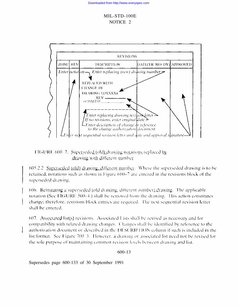
Downloaded from http://www.everyspec.com
MIL-STD-100ENOTICE 2
APPENDIX E
DISTRIBUTION STATEMENTS
l0. General.
10.1 Scope. This Appendix pertains to the content of Distribution Statements, criteria forapplication and guidance for physical location on drawings. This Appendix is a mandatorypart of this standard. The information contained herein is intended for compliance.
20. Applicable documents.
20.1 Government documents. The following documents form a part of this Appendix to theextent specified:
MILITARY STANDARDS
MIL-STD-1806 Marking Technical Data Prepared by orfor the Department of Defense.
(Copies of federal and military specifications. standards, and handbooks are availablefrom the Standardization Documents Order Desk, Bldg 4D, 700 Robbins Avenue,Philadelphia. PA 19111-5094. For specific acquisition functions, these documents should beobtained from the contracting activity or as directed by the contractin activity. )
30. Definitions.
30.1 Definitions used in this appendix. For purposesMIL-STD- 1806 shall apply.
40. General requirement
40.1. Distribution statement and associated notices.export control warning notices, including abbreviatedMIL-STD-1806 (see 504) and the following:
of this appendix the definitions of
Distribution statements and associatcdnotices. shall be in accordance with
E-1
Supersedes page E-1 of 30 September 1991
Downloaded from http://www.everyspec.com
MIL-STD-100ENOTICE 2
Assigning statements and notices. Assignment of distribution statements and notices to 40.2engineering drawings and associated lists denote the extent to which they are available fordistribution, release and dissemination without additional approvals or authorization.Marking of associated lists shall be based on the content of the list and not the classifictitionof the drawing.
40.3 Applicability. Distribution statements shall be included on all drawings and associatedlists. For multi-sheet drawings except drawings in book-form, distribution statements shallbe included on all sheets. For drawings in book-form and multi-sheet associated lists,inclusion of distribution statements on sheet one shall suffice.
40.4 Abbreviated distribution statements and export control warning notices. When spacelimitations prohibit the use of entire notices or distribution statements, abbreviated notices ordistribution statements may be used and shall be in accordance with MIL-STD-1806.
40.5 Method of application. Statements and notices may be generated from digital data,applied by decals, rubber stamp or by direct lettering on the drawing. Lettering shall meetthe reproduction requirements of the engineering drawing and associated lists.
40.6 Size of lettering. Lettering shall be equal to or larger than the size of the largest notelettering on the drawing or associated list.
40.7 Color of lettering All lettering and notations shall be black.
40.8 Location on drawings and associated lists. Graphics and textual data permitting,Distribution Statements shall be located on drawings and lists in accordance with Figures E-1through E–6. Otherwise the required statements and associated notices are to be located insimilarly prominent areas.
40.8.1 Location of associated notices. Export control warning notices required in associationwith Distribution Statements shall be located in the same general area as the DistributionStatement
E-2Supersedes page E-2 of 30 September 1991
Downloaded from http://www.everyspec.com