MIL-DTL-62177E SUPERSEDING DETAIL SPECIFICATION … · MIL-L-21260 - Lubricating Oil, Internal...
26
INCH POUND MIL-DTL-62177E 17 September 1998 SUPERSEDING MIL-PRF-62177D 7 May 1996 DETAIL SPECIFICATION ENGINE, DIESEL: 12 CYLINDER, 90° V-TYPE, 750 H.P., AVDS1790-2, AVDS1790-2A, AVDS1790-2C, AVDS1790-2D, AVDS1790-2DR, AVDS1790-2CA AND AVDS1790-2DA This specification is approved for use by all Departments and Agencies of the Department of Defense. 1. SCOPE 1.1 Scope. This specification covers 7 types of 12-cylinder, 90° V-type, air-cooled, 4 stroke-cycle, turbo-supercharged, internal-combustion, compression-ignition (diesel) engines for use in military vehicles (see 6.1). 1.2 Classification. This engine is classified in seven configurations as follows (see 6.2): Type I - AVDS1790-2 (Army Drawing 8725265) furnished with air-cooled generator and associated accessory drive. Type II - AVDS1790-2A (Army Drawing 10912450) furnished with air-cooled generator and associated accessory drive. Type III - AVDS1790-2C (Army Drawing 11682700). Furnished with oil-cooled alternator and associated accessory drive. Type IV - AVDS1790-2D (Army Drawing 11684000) furnished with air-cooled generator and associated accessory drive. Beneficial comments (recommendations, additions, deletions) and any pertinent data which may be of use in improving this document should be addressed to: U.S. Army Tank-automotive and Armaments Command, ATTN: AMSTA-TR-E/BLUE, Warren, MI 48397-5000, by using the Standardization Document Improvement Proposal (DD Form 1426) appearing at the end of this document or by letter. AMSC N/A FSC 2815 DISTRIBUTION STATEMENT A. Approved for public release; distribution is unlimited.
-
Upload
vuongkhanh -
Category
Documents
-
view
227 -
download
0
Transcript of MIL-DTL-62177E SUPERSEDING DETAIL SPECIFICATION … · MIL-L-21260 - Lubricating Oil, Internal...

INCH POUNDMIL-DTL-62177E17 September 1998SUPERSEDINGMIL-PRF-62177D7 May 1996
DETAIL SPECIFICATION
ENGINE, DIESEL: 12 CYLINDER, 90° V-TYPE, 750 H.P.,AVDS1790-2, AVDS1790-2A, AVDS1790-2C, AVDS1790-2D,
AVDS1790-2DR, AVDS1790-2CA AND AVDS1790-2DA
This specification is approved for use by all Departments and Agencies of theDepartment of Defense.
1. SCOPE
1.1 Scope. This specification covers 7 types of 12-cylinder, 90° V-type, air-cooled,4 stroke-cycle, turbo-supercharged, internal-combustion, compression-ignition (diesel) enginesfor use in military vehicles (see 6.1).
1.2 Classification. This engine is classified in seven configurations as follows (see 6.2):
Type I - AVDS1790-2 (Army Drawing 8725265) furnished withair-cooled generator and associated accessory drive.
Type II - AVDS1790-2A (Army Drawing 10912450) furnishedwith air-cooled generator and associated accessory drive.
Type III - AVDS1790-2C (Army Drawing 11682700). Furnished with oil-cooled alternator and associated accessory drive.
Type IV - AVDS1790-2D (Army Drawing 11684000) furnishedwith air-cooled generator and associated accessory drive.
Beneficial comments (recommendations, additions, deletions) and any pertinent data which maybe of use in improving this document should be addressed to: U.S. Army Tank-automotive andArmaments Command, ATTN: AMSTA-TR-E/BLUE, Warren, MI 48397-5000, by using theStandardization Document Improvement Proposal (DD Form 1426) appearing at the end of thisdocument or by letter.AMSC N/A FSC 2815DISTRIBUTION STATEMENT A. Approved for public release; distribution is unlimited.
MIL-DTL-62177E
2
Type V - AVDS1790-2DR (Army Drawing 11684150) furnishedwith air-cooled generator and associated accessory driveand an auxiliary power take-off drive.
Type VI - AVDS1790-2CA (Army Drawing 12314611) furnishedwith oil-cooled alternator and associated accessory driveand the Clean Air System, composed of the Dust Detectorand Dust Ejector.
Type VII - AVDS1790-2DA (Army Drawing 12314641) furnishedwith air-cooled generator and associated accessory driveand the Clean Air System, composed of the Dust Detectorand Dust Ejector.
2. APPLICABLE DOCUMENTS
2.1 General. The documents listed in this section are specified in sections 3 and 4 of thisspecification. This section does not include documents in other sections of this specification orrecommended for additional information or as examples. While every effort has been made toensure the completeness of this list, document users are cautioned that they must meet allspecified requirements documents cited in sections 3 and 4 of this specification, whether or notthey are listed.
2.2 Government documents.
2.2.1 Specifications, standards, and handbooks. The following specifications, standards,and handbooks form a part of this document to the extent specified herein. Unless otherwisespecified, the issues of these documents are those listed in the issue of the Department ofDefense Index of Specifications and Standards (DoDISS) and supplement thereto, cited in thesolicitation (see 6.2).
SPECIFICATIONS
FEDERAL
A-A-50271 - Plates, Identification.A-A-52524 - Seal, Plain, and Seal, Plain, Encased: Fluid, Radial,
Single and Multiple Lip Sealing Member.A-A-52557 - Fuel Oil, Diesel; For Posts, Camps And Stations.
DEPARTMENT OF DEFENSE
MIL-PRF-2104 - Lubricating Oil, Internal Combustion Engine, Combat/Tactical Service.
MIL-PRF-10924 - Grease, Automotive and Artillery.
MIL-DTL-62177E
3
MIL-L-21260 - Lubricating Oil, Internal Combustion Engine,Preservative and Break-in.
MIL-L-46167 - Lubricating Oil, Internal Combustion Engine, Arctic.MIL-PRF-46736 - Filter Element, Intake Air Cleaner: Dry Type.MIL-PRF-62576 - Regulator, Engine Generator.
(Unless otherwise indicated, copies of the above specifications, standards, andhandbooks are available from the Standardization Document Order Desk, 700 Robbins Avenue,Building 4D, Philadelphia, PA 19111-5094.)
2.2.2 Other Government documents, drawings, and publications. The following otherGovernment documents, drawings, and publications form a part of this specification to the extentspecified herein. Unless otherwise specified, the issues are those cited in the solicitation.
DRAWINGS
8725265 - Engine Assembly (AVDS1790-2).10912450 - Engine Assembly (AVDS1790-2A).11682700 - Engine Assembly (AVDS1790-2C).11684000 - Engine Assembly (AVDS1790-2D).11684150 - Engine Assembly (AVDS1790-2DR).12314611 - Engine Assembly (AVDS1790-2CA).12314641 - Engine Assembly (AVDS1790-2DA).12354334 - Regulator - Solid State.
(Application for copies should be addressed to the U.S. Army Tank-automotive andArmaments Command, ATTN: AMSTA-TR-E/BLUE, Warren, MI 48397-5000.)
2.3 Non-Government publications. The following document(s) form a part of thisdocument to the extent specified herein. Unless otherwise specified, the issues of the documentswhich are DoD adopted are those listed in the issue of the DoDISS cited in the solicitation.Unless otherwise specified, the issues of documents not listed in the DoDISS are the issue of thedocuments cited in the solicitation (see 6.2).
NATO INTERNATIONAL STAFF - DEFENSE SUPPORT DIVISION
AC/225 (Panel II) D131 (part II) - NATO Standard Engine Laboratory Test for Diesel and Gasoline Engines.
(Application for copies should be addressed to NATO, Military Agency forStandardization (MAS), 35 Chesham Place, London SWI, England.)
MIL-DTL-62177E
4
2.4 Order of precedence. In the event of a conflict between the text of this document andthe references cited herein, the text of this document takes precedence. Nothing in thisdocument, however, supersedes applicable laws and regulations unless a specific exemption hasbeen obtained.
3. REQUIREMENTS
3.1 First article. When specified (see 6.2), a sample shall be subjected to first articleinspection in accordance with 4.3.
3.2 Design, materials, and manufacturing processes. Unless otherwise specified, thedesign, materials and manufacturing process selection is the prerogative of the contractor as longas all articles submitted to the Government fully meet the operating, interface, support andownership, and operating environment requirements specified (see 4.5.1).
3.2.1 Design and manufacturing processes. The design and construction of the dieselengine shall be in accordance with the applicable Army drawing for the engine type as follows(see 1.2, 4.5.1, 4.5.2 and 6.2):
Type I - 8725265Type II - 10912450
Type III - 11682700 Type IV - 11684000
Type V - 11684150Type VI - 12314611Type VII - 12314641
3.2.2 Recycled, recovered, or environmentally preferable materials. Recycled,recovered, or environmentally preferable materials should be used to the maximum extentpossible provided that the material meets or exceeds the operational and maintenancerequirements, and promotes economically advantageous life cycle costs.
3.2.3 Greases. Engine greases shall conform to MIL-PRF-10924, where applicable(see 4.5.1).
3.2.4 Protective coatings. Exposed exterior surfaces of the engine and its components,except the turbocharger compressor housing and the fuel injection pump aluminum parts, shallbe leaned, and painted or treated for corrosion resistance as specified on the applicable drawings(see 4.5.1 and 4.5.2).
3.2.5 Metals. The use of dissimilar metals in intimate metal to metal contact shall beavoided.

MIL-DTL-62177E
5
3.3 Operating requirements. Each engine shall provide the following functional,operational, and performance capabilities.
3.3.1 Break-in. The engine shall receive a break-in period that meets thetime/speed/torque schedule specified in 4.6.2.1.12.
3.3.2 Performance. The engine performance requirements shall be met under thefollowing conditions:
a. Fuel. Diesel fuel conforming to A-A-52557, grade DF-2 shall be used.b. Lubricating oil. Unless otherwise specified herein, lubricating oil conforming to
the seasonal requirements of MIL-PRF-2104 or MIL-L-21260 (-10 to 115 degreesFahrenheit (°F) [(23 to 46 degrees Celsius (°C)] and MIL-L-46167 (-65 to 0°F)(-54 to -18°C) shall be used.
c. Rated operating conditions. The engine performance requirements specified in3.3.3 through 3.3.14.1 shall be met after correction of measured parameters to thefollowing:
1. Dry air barometric pressure: 29.92 inches (in.) mercury (Hg),(101.3 kilopascal (kPa)) Hg.
2. Fuel temperature at the secondary fuel filter: 60°F (16°C).3. Turbocharger inlet air temperature: 60°F.
3.3.3 Leakage. The engine shall not leak fluid more than the degree defined as “droplet”(see 4.5.2 and 6.4).
3.3.4 Governor. The engine governor shall limit the engine speed as follows,(see 4.6.2.1.1):
a. Auxiliary drive operation 1750 to 1800 revolutions per minute(For AVDS1790-2DR engine only) (rpm).
b. Idle 700 to 750 rpm.c. Speed (no load) 2600 to 2660 rpm.d. Speed (full load) 2400 to 2450 rpm.
The engine speed shall stabilize within 30 seconds after the full power setting is reached.
3.3.5 Gross corrected brake horsepower (GCBHP). The engine shall develop not lessthan 735 nor more than 780 GCBHP at 2400 to 2450 rpm at the full power setting(see 4.6.2.1.2).
MIL-DTL-62177E
6
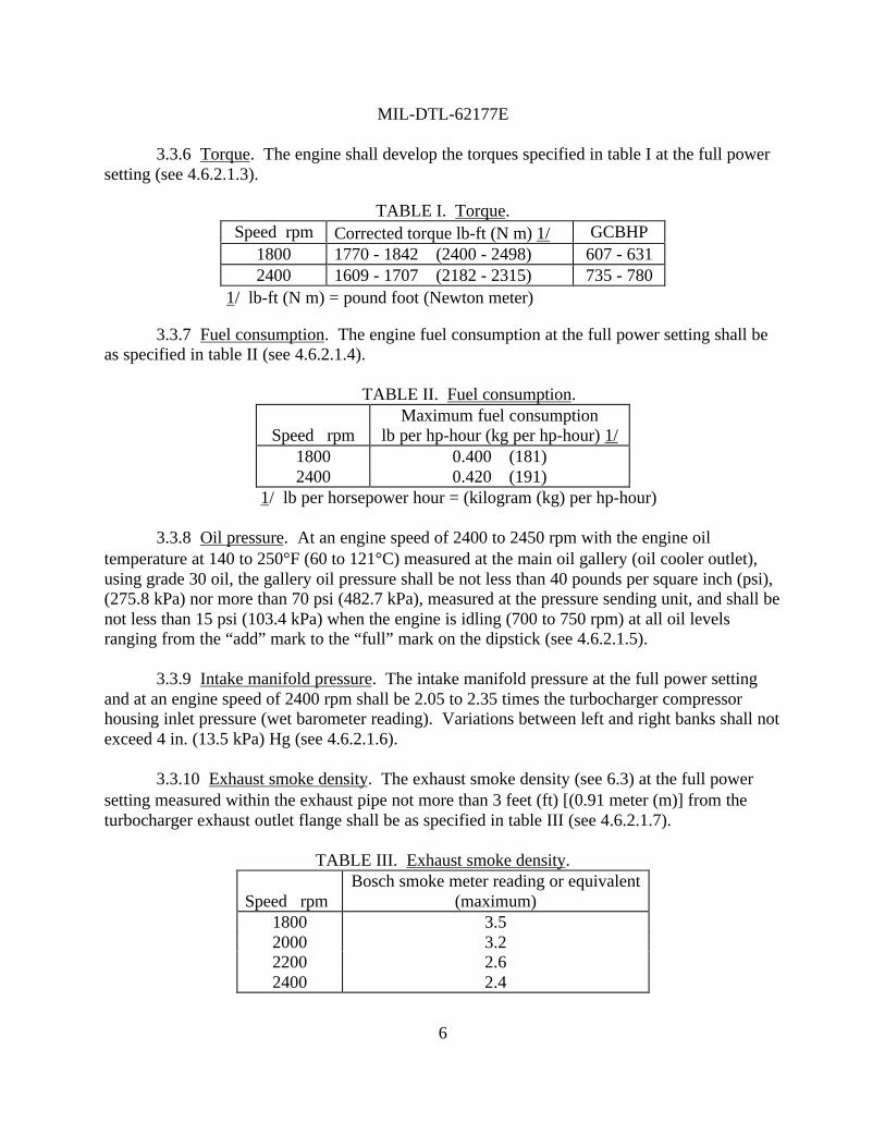
3.3.6 Torque. The engine shall develop the torques specified in table I at the full powersetting (see 4.6.2.1.3).
TABLE I. Torque.Speed rpm Corrected torque lb-ft (N⋅m) 1/ GCBHP
1800 1770 - 1842 (2400 - 2498) 607 - 6312400 1609 - 1707 (2182 - 2315) 735 - 780
1/ lb-ft (N⋅m) = pound foot (Newton meter)
3.3.7 Fuel consumption. The engine fuel consumption at the full power setting shall beas specified in table II (see 4.6.2.1.4).
TABLE II. Fuel consumption.
Speed rpmMaximum fuel consumption
lb per hp-hour (kg per hp-hour) 1/1800 0.400 (181)2400 0.420 (191)
1/ lb per horsepower hour = (kilogram (kg) per hp-hour)
3.3.8 Oil pressure. At an engine speed of 2400 to 2450 rpm with the engine oiltemperature at 140 to 250°F (60 to 121°C) measured at the main oil gallery (oil cooler outlet),using grade 30 oil, the gallery oil pressure shall be not less than 40 pounds per square inch (psi),(275.8 kPa) nor more than 70 psi (482.7 kPa), measured at the pressure sending unit, and shall benot less than 15 psi (103.4 kPa) when the engine is idling (700 to 750 rpm) at all oil levelsranging from the “add” mark to the “full” mark on the dipstick (see 4.6.2.1.5).
3.3.9 Intake manifold pressure. The intake manifold pressure at the full power settingand at an engine speed of 2400 rpm shall be 2.05 to 2.35 times the turbocharger compressorhousing inlet pressure (wet barometer reading). Variations between left and right banks shall notexceed 4 in. (13.5 kPa) Hg (see 4.6.2.1.6).
3.3.10 Exhaust smoke density. The exhaust smoke density (see 6.3) at the full powersetting measured within the exhaust pipe not more than 3 feet (ft) [(0.91 meter (m)] from theturbocharger exhaust outlet flange shall be as specified in table III (see 4.6.2.1.7).
TABLE III. Exhaust smoke density.
Speed rpmBosch smoke meter reading or equivalent
(maximum)1800 3.52000 3.22200 2.62400 2.4
MIL-DTL-62177E
7
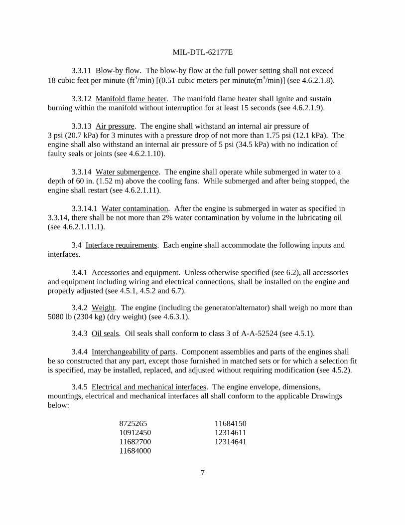
3.3.11 Blow-by flow. The blow-by flow at the full power setting shall not exceed18 cubic feet per minute (ft3/min) [(0.51 cubic meters per minute(m3/min)] (see 4.6.2.1.8).
3.3.12 Manifold flame heater. The manifold flame heater shall ignite and sustainburning within the manifold without interruption for at least 15 seconds (see 4.6.2.1.9).
3.3.13 Air pressure. The engine shall withstand an internal air pressure of3 psi (20.7 kPa) for 3 minutes with a pressure drop of not more than 1.75 psi (12.1 kPa). Theengine shall also withstand an internal air pressure of 5 psi (34.5 kPa) with no indication offaulty seals or joints (see 4.6.2.1.10).
3.3.14 Water submergence. The engine shall operate while submerged in water to adepth of 60 in. (1.52 m) above the cooling fans. While submerged and after being stopped, theengine shall restart (see 4.6.2.1.11).
3.3.14.1 Water contamination. After the engine is submerged in water as specified in3.3.14, there shall be not more than 2% water contamination by volume in the lubricating oil(see 4.6.2.1.11.1).
3.4 Interface requirements. Each engine shall accommodate the following inputs andinterfaces.
3.4.1 Accessories and equipment. Unless otherwise specified (see 6.2), all accessoriesand equipment including wiring and electrical connections, shall be installed on the engine andproperly adjusted (see 4.5.1, 4.5.2 and 6.7).
3.4.2 Weight. The engine (including the generator/alternator) shall weigh no more than5080 lb (2304 kg) (dry weight) (see 4.6.3.1).
3.4.3 Oil seals. Oil seals shall conform to class 3 of A-A-52524 (see 4.5.1).
3.4.4 Interchangeability of parts. Component assemblies and parts of the engines shallbe so constructed that any part, except those furnished in matched sets or for which a selection fitis specified, may be installed, replaced, and adjusted without requiring modification (see 4.5.2).
3.4.5 Electrical and mechanical interfaces. The engine envelope, dimensions,mountings, electrical and mechanical interfaces all shall conform to the applicable Drawingsbelow:
8725265 1168415010912450 1231461111682700 1231464111684000

MIL-DTL-62177E
8
3.5 Support and ownership requirements. Each engine shall possess the following lifecycle ownership characteristics.
3.5.1 Endurance. The engine shall retain 90% of the rated power after being subjected toa 400-hour endurance test cycle, operating in an operating profile scenario (see 4.6.4.1).
3.5.2 Identification marking. Parts requiring identification shall be identified inaccordance with the requirements of the specific product drawings (see 4.5.2).
3.5.3 Nameplates. Unless otherwise specified in applicable drawings (see 6.2), thenameplate, data and instruction plates shall conform to A-A-50271 (see 4.5.2).
3.5.4 Workmanship/safety. Manufacturing techniques shall not cause the degradation ofinherent engine reliability or durability, and shall pose no hazards, physically or electrically topersonnel operating the engine (see 4.5.2 and 4.6.4.2)
3.6 Operating environment requirements. Each engine shall operate under the followingenvironmental conditions, without degradation in performance.
3.6.1 Extreme-temperature starting ability. The engine shall start under the followingconditions (see 4.6.5.1):
a. After being cold-soaked to an ambient temperature of -25°F (-32°C) withoutexternal aids or benefit of solar radiation. (Cold-soak is to reduce the temperatureof the engine, fuel, and lubricating oil to within 5°F (-2.8°C) of the ambient airtemperature).
b. After being cold-soaked to an ambient temperature of -65°F, with thewinterization kit preheating the cold-soaked batteries and lubricating oil to-25°F.
c. After being operated at an ambient temperature of 115°F with exposure tomaximum solar radiation with the lubricating oil at the maximum attainabletemperature up to 250°F measured at the main oil gallery (oil cooler outlet).
3.6.2 High-temperature operation. Engine temperatures shall not exceed the followinglimits when operating at the maximum GCBHP full power setting (see table II) with an air inlettemperature of 115°F (see 4.6.5.2):
a. Lubricating oil temperature 250°F(measured at the main oil gallery;oil cooler outlet).
MIL-DTL-62177E
9
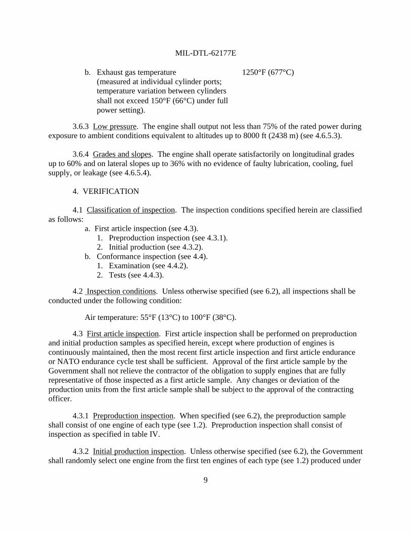
b. Exhaust gas temperature 1250°F (677°C)(measured at individual cylinder ports;temperature variation between cylindersshall not exceed 150°F (66°C) under fullpower setting).
3.6.3 Low pressure. The engine shall output not less than 75% of the rated power duringexposure to ambient conditions equivalent to altitudes up to 8000 ft (2438 m) (see 4.6.5.3).
3.6.4 Grades and slopes. The engine shall operate satisfactorily on longitudinal gradesup to 60% and on lateral slopes up to 36% with no evidence of faulty lubrication, cooling, fuelsupply, or leakage (see 4.6.5.4).
4. VERIFICATION
4.1 Classification of inspection. The inspection conditions specified herein are classifiedas follows:
a. First article inspection (see 4.3).1. Preproduction inspection (see 4.3.1).2. Initial production (see 4.3.2).
b. Conformance inspection (see 4.4).1. Examination (see 4.4.2).2. Tests (see 4.4.3).
4.2 Inspection conditions. Unless otherwise specified (see 6.2), all inspections shall beconducted under the following condition:
Air temperature: 55°F (13°C) to 100°F (38°C).
4.3 First article inspection. First article inspection shall be performed on preproductionand initial production samples as specified herein, except where production of engines iscontinuously maintained, then the most recent first article inspection and first article enduranceor NATO endurance cycle test shall be sufficient. Approval of the first article sample by theGovernment shall not relieve the contractor of the obligation to supply engines that are fullyrepresentative of those inspected as a first article sample. Any changes or deviation of theproduction units from the first article sample shall be subject to the approval of the contractingofficer.
4.3.1 Preproduction inspection. When specified (see 6.2), the preproduction sampleshall consist of one engine of each type (see 1.2). Preproduction inspection shall consist ofinspection as specified in table IV.
4.3.2 Initial production inspection. Unless otherwise specified (see 6.2), the Governmentshall randomly select one engine from the first ten engines of each type (see 1.2) produced under
MIL-DTL-62177E
10
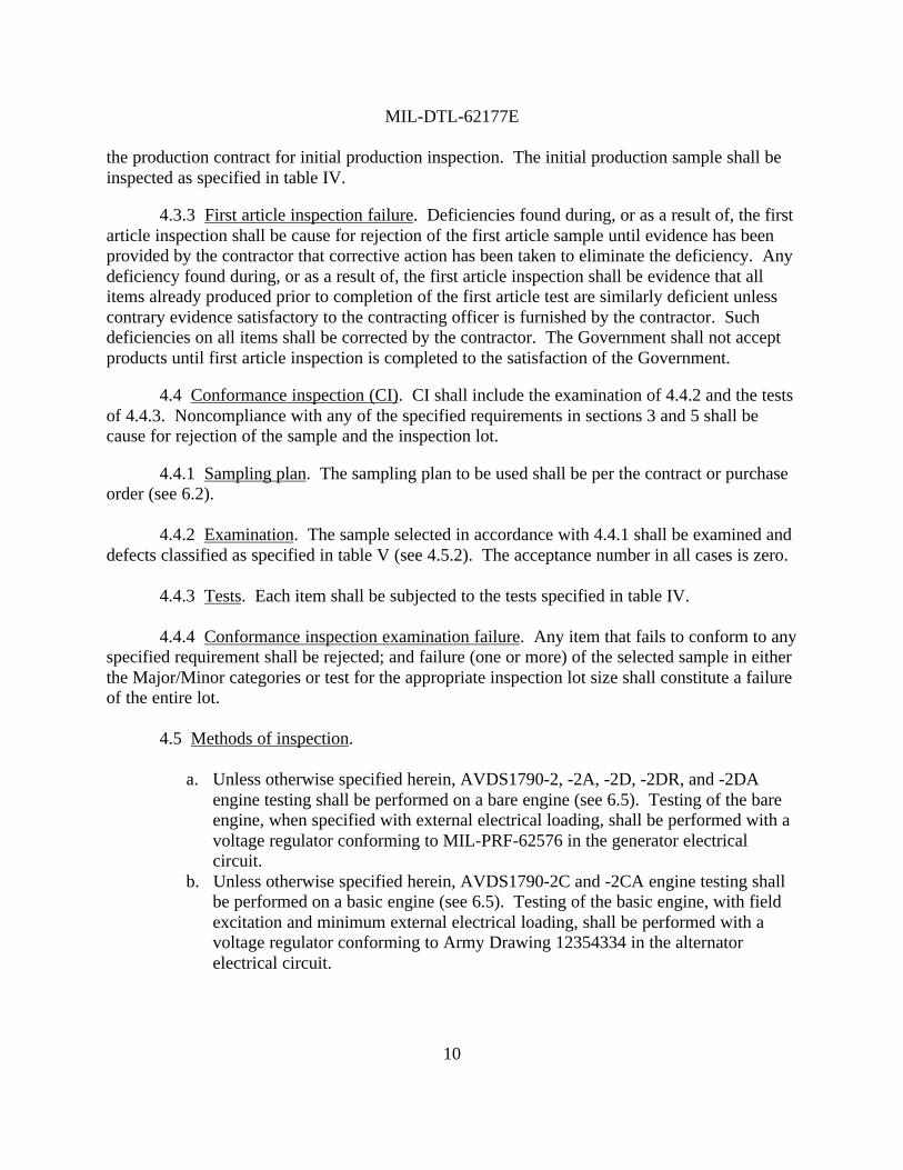
the production contract for initial production inspection. The initial production sample shall beinspected as specified in table IV.
4.3.3 First article inspection failure. Deficiencies found during, or as a result of, the firstarticle inspection shall be cause for rejection of the first article sample until evidence has beenprovided by the contractor that corrective action has been taken to eliminate the deficiency. Anydeficiency found during, or as a result of, the first article inspection shall be evidence that allitems already produced prior to completion of the first article test are similarly deficient unlesscontrary evidence satisfactory to the contracting officer is furnished by the contractor. Suchdeficiencies on all items shall be corrected by the contractor. The Government shall not acceptproducts until first article inspection is completed to the satisfaction of the Government.
4.4 Conformance inspection (CI). CI shall include the examination of 4.4.2 and the testsof 4.4.3. Noncompliance with any of the specified requirements in sections 3 and 5 shall because for rejection of the sample and the inspection lot.
4.4.1 Sampling plan. The sampling plan to be used shall be per the contract or purchaseorder (see 6.2).
4.4.2 Examination. The sample selected in accordance with 4.4.1 shall be examined anddefects classified as specified in table V (see 4.5.2). The acceptance number in all cases is zero.
4.4.3 Tests. Each item shall be subjected to the tests specified in table IV.
4.4.4 Conformance inspection examination failure. Any item that fails to conform to anyspecified requirement shall be rejected; and failure (one or more) of the selected sample in eitherthe Major/Minor categories or test for the appropriate inspection lot size shall constitute a failureof the entire lot.
4.5 Methods of inspection.
a. Unless otherwise specified herein, AVDS1790-2, -2A, -2D, -2DR, and -2DAengine testing shall be performed on a bare engine (see 6.5). Testing of the bareengine, when specified with external electrical loading, shall be performed with avoltage regulator conforming to MIL-PRF-62576 in the generator electricalcircuit.
b. Unless otherwise specified herein, AVDS1790-2C and -2CA engine testing shallbe performed on a basic engine (see 6.5). Testing of the basic engine, with fieldexcitation and minimum external electrical loading, shall be performed with avoltage regulator conforming to Army Drawing 12354334 in the alternatorelectrical circuit.
MIL-DTL-62177E
11
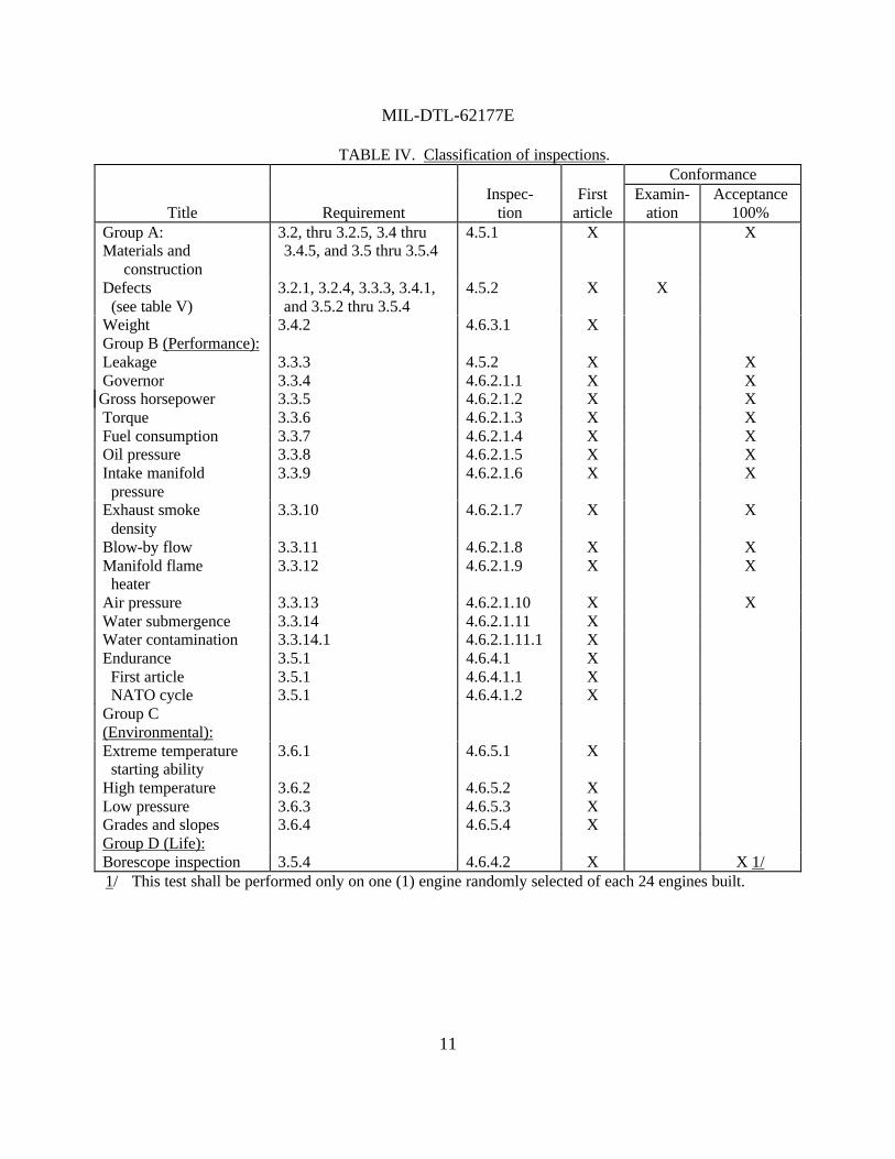
TABLE IV. Classification of inspections.Conformance
Title RequirementInspec-
tionFirst
articleExamin-
ationAcceptance
100%Group A:Materials and
construction
3.2, thru 3.2.5, 3.4 thru3.4.5, and 3.5 thru 3.5.4
4.5.1 X X
Defects (see table V)
3.2.1, 3.2.4, 3.3.3, 3.4.1,and 3.5.2 thru 3.5.4
4.5.2 X X
Weight 3.4.2 4.6.3.1 XGroup B (Performance):Leakage 3.3.3 4.5.2 X XGovernor 3.3.4 4.6.2.1.1 X XGross horsepower 3.3.5 4.6.2.1.2 X XTorque 3.3.6 4.6.2.1.3 X XFuel consumption 3.3.7 4.6.2.1.4 X XOil pressure 3.3.8 4.6.2.1.5 X XIntake manifold pressure
3.3.9 4.6.2.1.6 X X
Exhaust smoke density
3.3.10 4.6.2.1.7 X X
Blow-by flow 3.3.11 4.6.2.1.8 X XManifold flame heater
3.3.12 4.6.2.1.9 X X
Air pressure 3.3.13 4.6.2.1.10 X XWater submergence 3.3.14 4.6.2.1.11 XWater contamination 3.3.14.1 4.6.2.1.11.1 XEndurance 3.5.1 4.6.4.1 X First article 3.5.1 4.6.4.1.1 X NATO cycle 3.5.1 4.6.4.1.2 XGroup C(Environmental):Extreme temperature starting ability
3.6.1 4.6.5.1 X
High temperature 3.6.2 4.6.5.2 XLow pressure 3.6.3 4.6.5.3 XGrades and slopes 3.6.4 4.6.5.4 XGroup D (Life):Borescope inspection 3.5.4 4.6.4.2 X X 1/1/ This test shall be performed only on one (1) engine randomly selected of each 24 engines built.
MIL-DTL-62177E
12
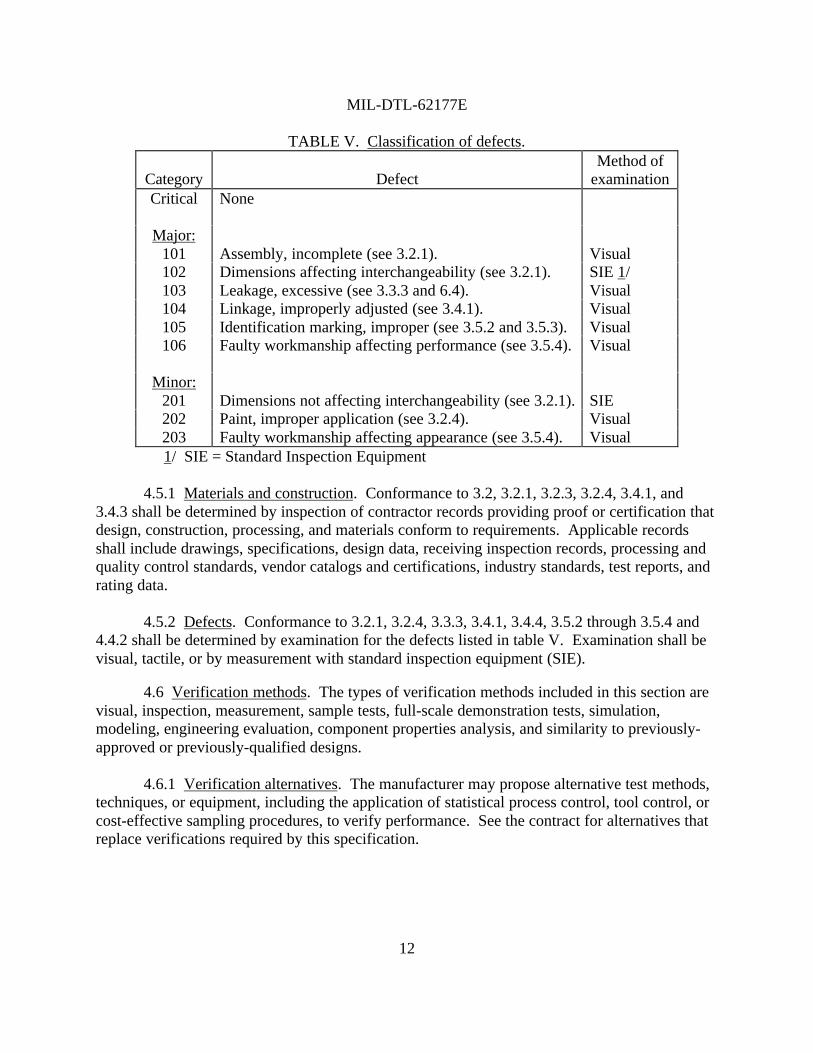
TABLE V. Classification of defects.
Category DefectMethod of
examinationCritical None
Major:101 Assembly, incomplete (see 3.2.1). Visual102 Dimensions affecting interchangeability (see 3.2.1). SIE 1/103 Leakage, excessive (see 3.3.3 and 6.4). Visual104 Linkage, improperly adjusted (see 3.4.1). Visual105 Identification marking, improper (see 3.5.2 and 3.5.3). Visual106 Faulty workmanship affecting performance (see 3.5.4). Visual
Minor:201 Dimensions not affecting interchangeability (see 3.2.1). SIE202 Paint, improper application (see 3.2.4). Visual203 Faulty workmanship affecting appearance (see 3.5.4). Visual
1/ SIE = Standard Inspection Equipment
4.5.1 Materials and construction. Conformance to 3.2, 3.2.1, 3.2.3, 3.2.4, 3.4.1, and3.4.3 shall be determined by inspection of contractor records providing proof or certification thatdesign, construction, processing, and materials conform to requirements. Applicable recordsshall include drawings, specifications, design data, receiving inspection records, processing andquality control standards, vendor catalogs and certifications, industry standards, test reports, andrating data.
4.5.2 Defects. Conformance to 3.2.1, 3.2.4, 3.3.3, 3.4.1, 3.4.4, 3.5.2 through 3.5.4 and4.4.2 shall be determined by examination for the defects listed in table V. Examination shall bevisual, tactile, or by measurement with standard inspection equipment (SIE).
4.6 Verification methods. The types of verification methods included in this section arevisual, inspection, measurement, sample tests, full-scale demonstration tests, simulation,modeling, engineering evaluation, component properties analysis, and similarity to previously-approved or previously-qualified designs.
4.6.1 Verification alternatives. The manufacturer may propose alternative test methods,techniques, or equipment, including the application of statistical process control, tool control, orcost-effective sampling procedures, to verify performance. See the contract for alternatives thatreplace verifications required by this specification.
MIL-DTL-62177E
13
4.6.2 Operating requirements verification.
4.6.2.1 Performance tests. The performance tests may be run concurrently with thebreak-in specified in 3.3.1. The engine performance shall be required under the followingconditions:
a. The engine speeds shall be governed as specified in 3.3.4.b. The engine shall function with external interface inputs as follows:
Fuel supply flow rate (minimum) 1400 lb (635 kg) per hour at 2400 rpm.Fuel supply pressure (minimum) 3 psi.Combustion air restriction 20 in. (0.51 m) of water (maximum) (1.5 in. Hg) at 2400 rpm.Intake air filter Equal to the requirements of
MIL-PRF-46736.Cooling airflow 24 000 ft3/min (672 m3/min) approximate.
c. Diesel fuel conforming to A-A-52557, grade DF-2 shall be used. MIL-L-21260,type I (-10 to 115°F) and MIL-L-46167 (-65 to 0°F) shall be used.
4.6.2.1.1 Governor. To determine conformance to 3.3.4, a bare/basic engine (see 6.5)shall be operated at full power rpm, high idle rpm, and low idle rpm. On the AVDS1790-2DRengine only, the rpm of the auxiliary drive operation shall be checked.
4.6.2.1.2 Gross hp. To determine conformance to 3.3.5, the engine shall be operated at400 to 2450 rpm at the full power setting. The corrected gross hp shall be calculated andrecorded.
4.6.2.1.3 Torque. To determine conformance to 3.3.6, the engine shall be operated at1800 and 2400 rpm at the full power setting. The corrected torque is a value that can becalculated from the GCBHP.
4.6.2.1.4 Fuel consumption. To determine conformance to 3.3.7, the engine shall beoperated at 1800 and 2400 rpm at the full power setting under full load. The corrected fuelconsumption shall be calculated and recorded.
4.6.2.1.5 Oil pressure. To determine conformance to 3.3.8, the engine shall be operatedat 2400 rpm with the oil temperature at 140 to 250°F measured at the main oil gallery (oil cooleroutlet). The oil pressure shall be measured and recorded. Also, when the engine is idling, the oilpressure shall be measured and recorded.
4.6.2.1.6 Intake manifold pressure. To determine conformance to 3.3.9, the engine shallbe operated at 2400 rpm at the full power setting. The intake manifold pressure shall bemeasured and recorded.
MIL-DTL-62177E
14
4.6.2.1.7 Exhaust smoke density. To determine conformance to 3.3.10, the engine shallbe operated at 1800, 2000, 2200, and 2400 rpm at the full power setting. The exhaust smokedensity shall be measured not more than 3 ft from the turbocharger exhaust outlet flange andrecorded.
4.6.2.1.8 Blow-by flow. To determine conformance to 3.3.11, the engine shall run at2400 rpm at the full power setting with a blow-by flow meter or equivalent.
4.6.2.1.9 Manifold flame heater (if applicable). To determine conformance to 3.3.12, theengine shall be cranked and the manifold flame heater shall be checked if it has been energized.The results shall be recorded.
4.6.2.1.10 Air pressure. To determine conformance to 3.3.13, all engine openings shallbe closed to ambient with appropriate plugs and covers. A port shall be provided for applying airpressure into the engine crankcase with a gage and a shut-off valve. An air pressure of 3 psishall be applied for 3 minutes. Any pressure drop shall be measured. Also, an air pressure of5 psi shall be applied, and checked for any indication of faulty seals or joints.
4.6.2.1.11 Water submergence. To determine conformance to 3.3.14, the engine shall beoperated for 30 minutes while submerged in water (fresh water or 4% by volume salt water) to adepth of 60 in. above the cooling fans with the intake and exhaust ducted to the atmosphere. Theengine shall then be stopped for 3 minutes and shall then be restarted for an additional 15minutes. The basic engine (see 6.5) shall operate with field excitation only to the alternator,which shall operate at no load. The results shall be recorded.
4.6.2.1.11.1 Water contamination. To determine conformance to 3.3.14.1, the watercontamination in the lubricating oil shall be measured and recorded after the engine is subjectedto the test specified in 4.6.2.1.11.
4.6.2.1.12 Break-in. To determine conformance to 3.3.1, the engine shall follow thebreak-in schedule in table VI.
4.6.3 Interface requirements verification.
4.6.3.1 Weight. To determine conformance to 3.4.2, the engine, including the generatoror alternator, shall be weighed (dry weight).

MIL-DTL-62177E
15
TABLE VI. Break-in schedule.Run number Time minutes Speed rpm Torque lb ft (N⋅m)
1 10 Idle 700-750 Warm up2 15 1000 85 (115)3 15 1400 440 (597)4 20 1800 837 (1135)5 20 2200 1024 (1389)6 20 2400 1092 (1481)7 30 2400 1202 (1630)8 30 2400 Full power setting9 5 2400 Full power setting10 5 2200 Full power setting11 5 2000 Full power setting12 5 1800 Full power setting
NOTES:-Bare engine shall operate without generator (see 6.5).-Basic engine shall operate with alternator and field excitation only (see 6.5).-Engine shall operate on its designed oil system, not on a test cell oil system.-Check for low idle at 700 to 750 rpm - adjust if necessary.-Inspect visually for air, exhaust, oil, and fuel leaks.-Check governor high idle speed at 2600 to 2660 rpm (no load, dynamometer water off). If adjustment is required, recheck the horsepower at 1800 and 2400 rpm at the full power setting.-The governor shall be resealed after adjustment.
4.6.4 Support and ownership requirements verification.
4.6.4.1 Endurance. To determine conformance to 3.5.1, the engine shall be subjected toan applicable test as follows.
4.6.4.1.1 First article. The engine shall be tested as specified in table VII for 20 cycles.The engine shall require only minor services (such as replacing oil or fuel filter elements) duringthese runs. Adjustments or replacement of parts must have approval by the Government. Thetest shall be conducted under the following conditions:
a. Running time less than 30 minutes shall not be counted toward the fulfillment ofendurance hours.
b. The inlet air temperature shall be not less than 60°F nor more than 100°F.
MIL-DTL-62177E
16
c. Electrical loading:1. Bare engine (see 6.5). A bare engine shall have a 300 ampere (A) direct
current (dc) generator installed with an applicable voltage regulator. Thegenerator shall operate at 100 ± 10 A throughout the test.
2. Basic engine (see 6.5). A basic engine, with the applicable voltage regulator,shall have its generator (alternator) operated at 200 ± 10 A throughout the test.
d. After the break-in and before initiation of the test, the engine shall be borescopeinspected and the condition of the cylinders recorded.
e. The engine shall operate on its designed oil system, not on a test cell system. Atspecified idle periods, engine lubricating oil level shall be checked with enginedipstick and oil shall be added to reach full mark on dipstick. Quantity of oiladded shall be recorded. At the end of every 5th test cycle, brake specific oilconsumption (BSOC) shall be calculated based on total oil used and averagehorsepower hours. Oil consumption shall not exceed 0.0075 pound perbrakehorsepower-hour (lb/bhp-hr), (0.0034 kg/bhp-hr).
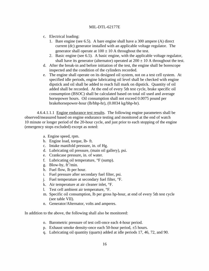
4.6.4.1.1.1 Engine endurance test results. The following engine parameters shall beobserved/measured based on engine endurance testing and monitored at the end of watch10 minute or longer period of the 20-hour cycle, and just prior to each stopping of the engine(emergency stops excluded) except as noted:
a. Engine speed, rpm.b. Engine load, torque, lb- ft.c. Intake manifold pressure, in. of Hg.d. Lubricating oil pressure, (main oil gallery), psi.e. Crankcase pressure, in. of water.f. Lubricating oil temperature, °F (sump).g. Blow-by, ft3/min.h. Fuel flow, lb per hour.i. Fuel pressure after secondary fuel filter, psi.j. Fuel temperature at secondary fuel filter, °F.k. Air temperature at air cleaner inlet, °F.l. Test cell ambient air temperature, °F.m. Specific oil consumption, lb per gross hp-hour, at end of every 5th test cycle
(see table VII).n. Generator/Alternator, volts and amperes.
In addition to the above, the following shall also be monitored:
o. Barometric pressure of test cell-once each 4-hour period.p. Exhaust smoke density-once each 50-hour period, ±5 hours.q. Lubricating oil quantity (quarts) added at idle periods 17, 46, 72, and 90.

MIL-DTL-62177E
17
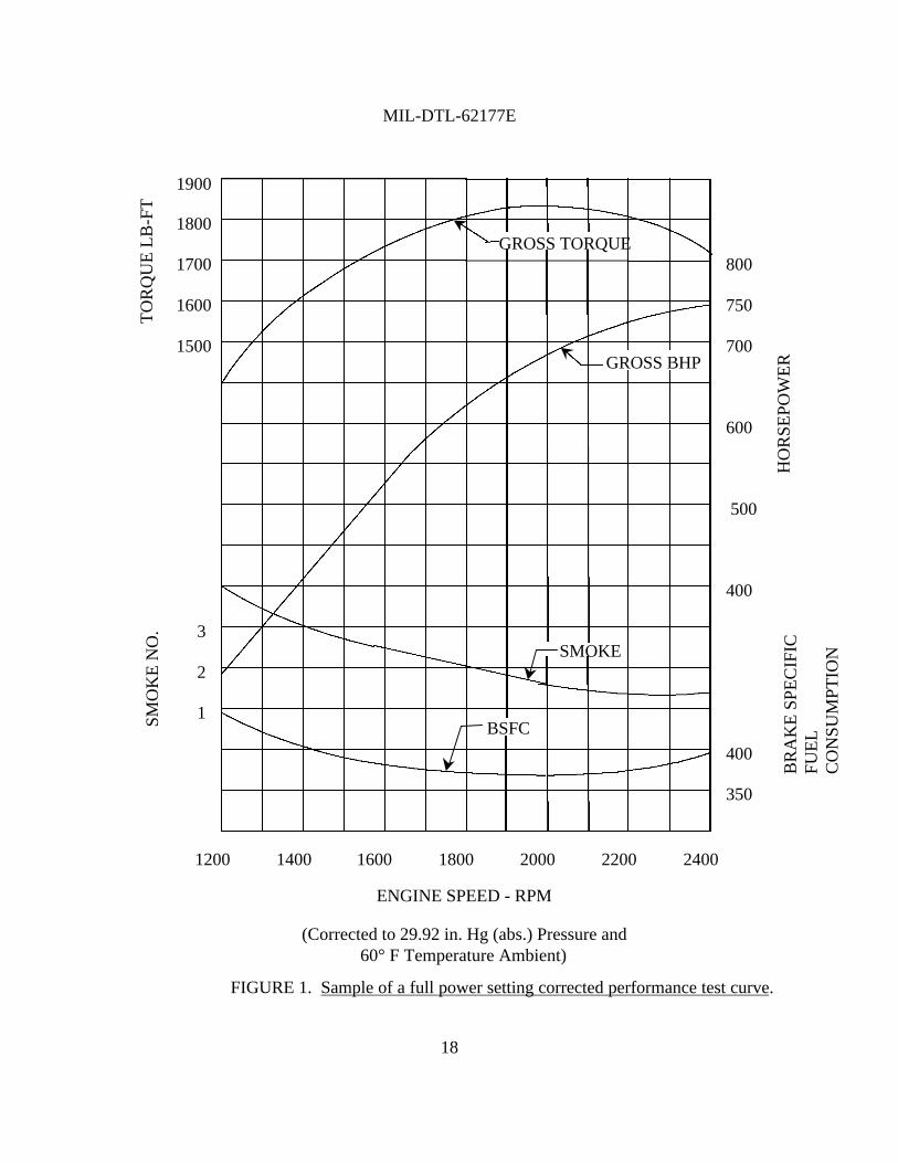
r. At the start and end of test and at the end of every 5th cycle, a full power settingcorrected performance test curve (see figure 1 for a sample) shall be plotted frommeasurements taken at a minimum of seven speed settings in descending order,the first setting being at rated speed. The speeds to be run shall include 1200,1400, 1600, 1800, 2000, 2200, and 2400 rpm.
4.6.4.1.1.2 Test cycle. The test cycle shall be as specified in table VII.
4.6.4.1.2 NATO cycle. When specified (see 6.2), the test according to 4.6.4.1.1.2. shallnot be required, and the first article test shall be the NATO cycle specified in 4.6.4.1.2.2. Theengine shall require only minor services (such as replacing oil or fuel filter elements) during thistest. Adjustments or replacement of parts must have approval by the Government. The test shallbe conducted under the following conditions:
a. Running time less than 30 minutes shall not be counted toward the fulfillment ofendurance hours.
b. The inlet air temperature shall be not less than 60°F nor more than 100°F.c. The engine shall be operated with the same cooling airflow as prevailed during
the full power setting (run number 8 of table VI).d. Electrical loading:
1. Bare engine (see 6.5). The bare engine shall have a 300 A dc generatorinstalled with an applicable voltage regulator. The generator shall operate at100 ± 10 A throughout the test.
2. Basic engine (see 6.5). The basic engine, with the applicable voltageregulator, shall have its generator (alternator) operated at 200 ± 10 Athroughout the test.
e. The lubricating oil and oil filter elements shall be replaced at the end of20 completed cycles (100 hours).
f. After the break-in and before initiation of the test, the engine shall be borescope inspected and the condition of the cylinders recorded.
MIL-DTL-62177E
18
FIGURE 1. Sample of a full power setting corrected performance test curve.
1
2
3
1900
1800
1700
1600
1500
800
750
700
600
500
400
400
350
2400220020001800160014001200
SMOKE
GROSS TORQUE
GROSS BHP
BSFC
TO
RQ
UE
LB
-FT
HO
RSE
POW
ER
SMO
KE
NO
.
(Corrected to 29.92 in. Hg (abs.) Pressure and60° F Temperature Ambient)
ENGINE SPEED - RPM
BR
AK
E S
PEC
IFIC
FUE
LC
ON
SUM
PTIO
N

MIL-DTL-62177E
19
TABLE VII. First article endurance test cycle.
Periodnumber
Periodlength
(minutes)Gross
hp rpmPeriodnumber
Periodlength
(minutes)Gross
hp rpm1 Start 0 0 47 30 300 16002 5 Idle 48 5 Idle3 5 300 1600 49 30 750 24004 120 600 2000 50 5 Idle5 5 300 1600 51 5 Stop6 5 Idle 52 5 Idle7 5 Stop 53 15 460 18008 5 Idle 54 5 Idle9 5 300 1600 55 5 Stop10 25 720 2200 56 30 550 190011 5 Idle 57 5 Idle12 50 650 2100 58 35 460 180013 5 Idle 59 5 Idle14 5 Stop 60 20 550 190015 5 Idle 61 5 Idle16 15 200 2400 62 15 200 140017 5 Idle 63 5 Idle18 5 Stop 64 5 300 160019 5 200 1400 65 5 Idle20 5 Idle 66 5 Stop21 30 200 1400 67 40 300 160022 5 Idle 68 5 Idle23 25 600 2000 69 20 460 180024 5 Idle 70 5 Idle25 5 Stop 71 10 200 140026 100 600 2000 72 5 Idle27 5 Idle 73 5 Stop28 5 Stop 74 5 300 160029 5 Idle 75 5 Idle30 15 750 2400 76 30 300 160031 5 Idle 77 5 Idle32 15 650 2100 78 15 750 240033 5 Idle 79 5 Idle34 5 300 1600 80 5 Stop35 5 Idle 81 10 750 240036 5 Stop 82 5 Idle37 5 Idle 83 25 550 1900
MIL-DTL-62177E
20
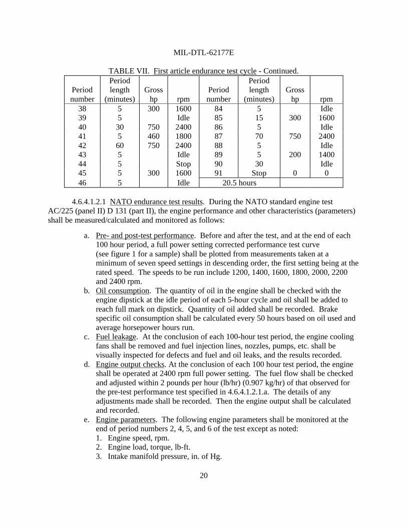
TABLE VII. First article endurance test cycle - Continued.
Periodnumber
Periodlength
(minutes)Gross
hp rpmPeriodnumber
Periodlength
(minutes)Gross
hp rpm38 5 300 1600 84 5 Idle39 5 Idle 85 15 300 160040 30 750 2400 86 5 Idle41 5 460 1800 87 70 750 240042 60 750 2400 88 5 Idle43 5 Idle 89 5 200 140044 5 Stop 90 30 Idle45 5 300 1600 91 Stop 0 046 5 Idle 20.5 hours
4.6.4.1.2.1 NATO endurance test results. During the NATO standard engine testAC/225 (panel II) D 131 (part II), the engine performance and other characteristics (parameters)shall be measured/calculated and monitored as follows:
a. Pre- and post-test performance. Before and after the test, and at the end of each100 hour period, a full power setting corrected performance test curve(see figure 1 for a sample) shall be plotted from measurements taken at aminimum of seven speed settings in descending order, the first setting being at therated speed. The speeds to be run include 1200, 1400, 1600, 1800, 2000, 2200and 2400 rpm.
b. Oil consumption. The quantity of oil in the engine shall be checked with theengine dipstick at the idle period of each 5-hour cycle and oil shall be added toreach full mark on dipstick. Quantity of oil added shall be recorded. Brakespecific oil consumption shall be calculated every 50 hours based on oil used andaverage horsepower hours run.
c. Fuel leakage. At the conclusion of each 100-hour test period, the engine coolingfans shall be removed and fuel injection lines, nozzles, pumps, etc. shall bevisually inspected for defects and fuel and oil leaks, and the results recorded.
d. Engine output checks. At the conclusion of each 100 hour test period, the engineshall be operated at 2400 rpm full power setting. The fuel flow shall be checkedand adjusted within 2 pounds per hour (lb/hr) (0.907 kg/hr) of that observed forthe pre-test performance test specified in 4.6.4.1.2.1.a. The details of anyadjustments made shall be recorded. Then the engine output shall be calculatedand recorded.
e. Engine parameters. The following engine parameters shall be monitored at theend of period numbers 2, 4, 5, and 6 of the test except as noted:1. Engine speed, rpm.2. Engine load, torque, lb-ft.3. Intake manifold pressure, in. of Hg.
MIL-DTL-62177E
21
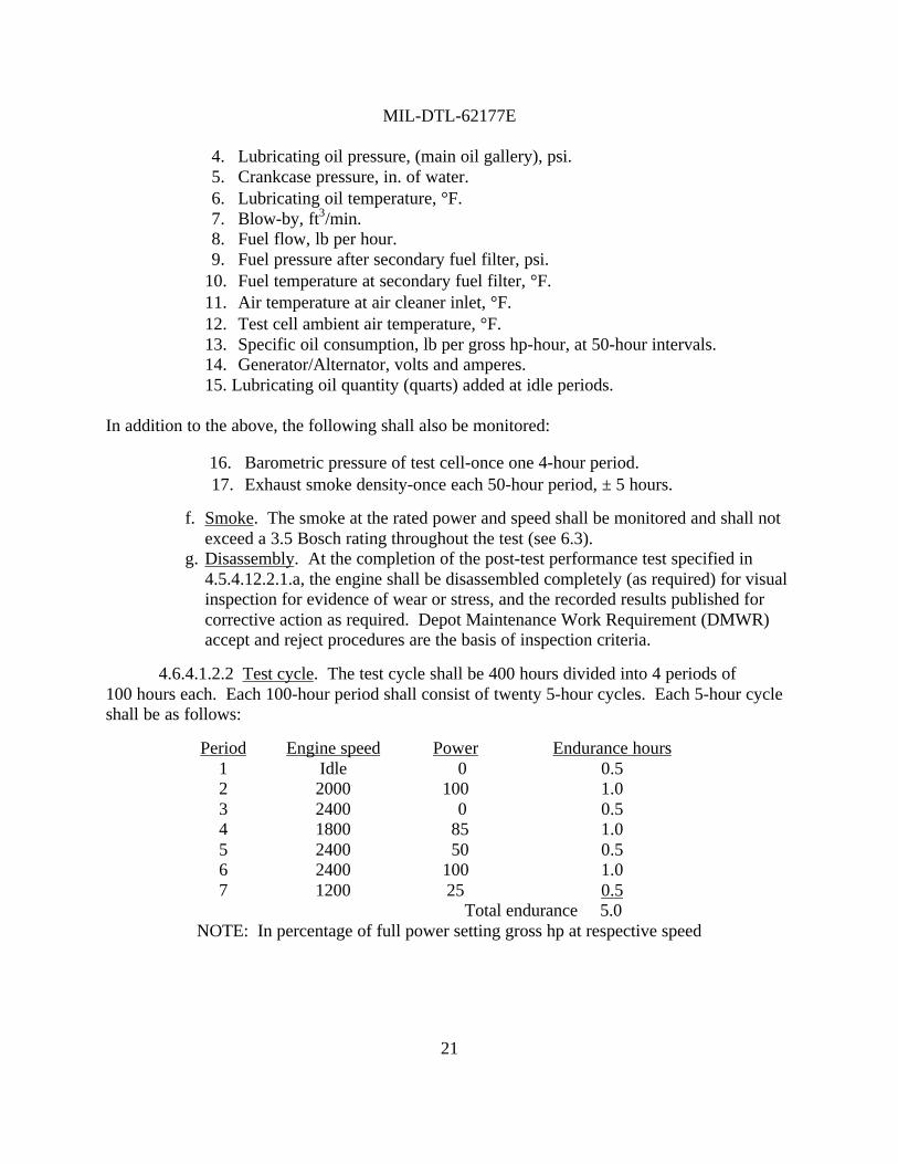
4. Lubricating oil pressure, (main oil gallery), psi.5. Crankcase pressure, in. of water.6. Lubricating oil temperature, °F.7. Blow-by, ft3/min.8. Fuel flow, lb per hour.9. Fuel pressure after secondary fuel filter, psi.
10. Fuel temperature at secondary fuel filter, °F.11. Air temperature at air cleaner inlet, °F.12. Test cell ambient air temperature, °F.13. Specific oil consumption, lb per gross hp-hour, at 50-hour intervals.14. Generator/Alternator, volts and amperes.15. Lubricating oil quantity (quarts) added at idle periods.
In addition to the above, the following shall also be monitored:
16. Barometric pressure of test cell-once one 4-hour period.17. Exhaust smoke density-once each 50-hour period, ± 5 hours.
f. Smoke. The smoke at the rated power and speed shall be monitored and shall notexceed a 3.5 Bosch rating throughout the test (see 6.3).
g. Disassembly. At the completion of the post-test performance test specified in4.5.4.12.2.1.a, the engine shall be disassembled completely (as required) for visualinspection for evidence of wear or stress, and the recorded results published forcorrective action as required. Depot Maintenance Work Requirement (DMWR)accept and reject procedures are the basis of inspection criteria.
4.6.4.1.2.2 Test cycle. The test cycle shall be 400 hours divided into 4 periods of100 hours each. Each 100-hour period shall consist of twenty 5-hour cycles. Each 5-hour cycleshall be as follows:
Period Engine speed Power Endurance hours12345
Idle2000240018002400
0100 0 85 50
0.51.00.51.00.5
6 2400 100 1.07 1200 25 0.5
Total endurance 5.0NOTE: In percentage of full power setting gross hp at respective speed

MIL-DTL-62177E
22
Electrical loadingEndurance hours -2, -2A, -2D, -2DR or -2DA engine -2C or -2CA engine
0-100101-200201-300301-400
100 ± 10 A200 ± 10 A200 ± 10 A300 ± 10 A
300 ± 10 A400 ± 10 A500 ± 10 A650 ± 10 A
4.6.4.2 Borescope inspection. To determine conformance to 3.5.4, the engine shall beborescope inspected and the condition of the cylinders recorded.
4.6.5 Operating environment requirements verification.
4.6.5.1 Extreme temperature starting ability. To determine conformance to 3.6.1, theengine shall be subjected to the following tests:
a. The engine shall be cold-soaked to an ambient temperature of -25°F. Then,without external aids or benefit of solar radiation, the engine shall be started.
b. The engine shall be cold-soaked to an ambient temperature of -65°F with thewinterization kit preheating the cold-soaked batteries and lubricating oil to-25°F). Then the engine shall be started.
c. The engine shall be operated at the full power setting and at an ambienttemperature of 115°F with exposure to maximum solar radiation until thelubricating oil reaches the maximum attainable temperature up to 250°F measuredat the main oil gallery (oil cooler outlet). Then the engine shall be stopped, andrestarted.
4.6.5.2 High temperature operation. To determine conformance to 3.6.2, the engine shallbe operated at the maximum GCBHP (see table I) with a maximum air inlet temperature of115°F. The lubricating oil temperature shall be measured at the main oil gallery (oil cooleroutlet), and the exhaust gas temperature at each cylinder port.
4.6.5.3 Low pressure. To determine conformance to 3.6.3, the engine shall be operatedat the following ambient conditions:
Elevation ft (m) Pressure in. of Hg (cm of Hg) Temperature3000 (914)4000 (1219)5000 (1524)6000 (1829)7000 (2134)8000 (2438)
26.8 (68.1)25.8 (65.5)24.9 (63.2)
24.0 (61)23.1 (58.7)22.2 (56.4)
115°F108°F (42°C)
100°F97°F (36°C)93°F (34°C)90°F (32°C)

MIL-DTL-62177E
23
4.6.5.4 Grades and slopes. To determine conformance to 3.6.4, the engine shall beoperated for not less than 30 minutes in each position of forward and backward inclinations of60% (31.0 degrees) and of left and right inclinations of 36% (19.8 degrees).
5. PACKAGING
5.1 Packaging. For acquisition purposes, the packaging requirements shall be asspecified in the contract or order (see 6.2). When actual packaging of materiel is to beperformed by DoD personnel, these personnel need to contact the responsible packaging activityto ascertain requisite packaging requirements. Packaging requirements are maintained by theInventory Control Point’s packaging activity within the Military Department or Defense Agency,or within the Military Department’s System Command. Packaging data retrieval is availablefrom the managing Military Department’s or Defense Agency’s automated packaging files, CD-ROM products, or by contacting the responsible packaging activity.
6. NOTES
(This section contains information of a general or explanatory nature which may behelpful, but is not mandatory.)
6.1 Intended use. The AVDS1790 series of engines as classified in 1.2 are intended tobe used for production, as spares, or as replacements in military combat and tactical transportvehicles. These series of engines are military unique because they are used on military combatvehicles that must operate satisfactorily and reliably at extreme ambient temperatures of -65°F to115°F.
6.2 Acquisition requirements. Acquisition documents must specify the following:
a. Title, number, and date of this specification.b Type of engine, applicable Army drawing no. (see 1.2 and 3.2.1).c. Issue of DoDISS to be cited in the solicitation, and if required, the specific issue
of individual documents referenced (see 2.2.1 and 2.3).d. If a first article sample is required (see 3.1).e. If all accessories and equipment will not be installed on engines and adjusted
(see 3.4.1).f. If nameplates will be other than as specified (see 3.5.3).g. If inspection conditions will be other than as specified (see 4.2).h. Arrangements for first article inspection and rights of the Government
(see 4.3.1 and 4.3.2).i. When first article preproduction inspection is other than as specified (see 4.3.1).j. If initial production inspection is other than as specified (see 4.3.2).k. Sampling plan (see 4.4.1).
MIL-DTL-62177E
24
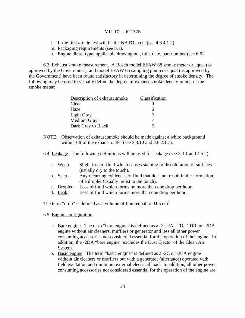
l. If the first article test will be the NATO cycle (see 4.6.4.1.2).m. Packaging requirements (see 5.1).n. Engine diesel type; applicable drawing no., title, date, part number (see 6.6).
6.3 Exhaust smoke measurement. A Bosch model EFAW 68 smoke meter or equal (asapproved by the Government), and model EFAW 65 sampling pump or equal (as approved bythe Government) have been found satisfactory in determining the degree of smoke density. Thefollowing may be used to visually define the degree of exhaust smoke density in lieu of thesmoke meter:
Description of exhaust smoke ClassificationClearHazeLight GrayMedium GrayDark Gray to Black
12345
NOTE: Observation of exhaust smoke should be made against a white backgroundwithin 3 ft of the exhaust outlet (see 3.3.10 and 4.6.2.1.7).
6.4 Leakage. The following definitions will be used for leakage (see 3.3.1 and 4.5.2).
a. Weep. Slight loss of fluid which causes staining or discoloration of surfaces(usually dry to the touch).
b. Seep. Any recurring evidences of fluid that does not result in the formationof a droplet (usually moist to the touch).
c. Droplet. Loss of fluid which forms no more than one drop per hour.d. Leak. Loss of fluid which forms more than one drop per hour.
The term “drop” is defined as a volume of fluid equal to 0.05 cm3.
6.5 Engine configuration.
a. Bare engine. The term “bare engine” is defined as a -2, -2A, -2D, -2DR, or -2DAengine without air cleaners, mufflers or generator and less all other powerconsuming accessories not considered essential for the operation of the engine. Inaddition, the -2DA “bare engine” excludes the Dust Ejector of the Clean AirSystem.
b. Basic engine. The term “basic engine” is defined as a -2C or -2CA enginewithout air cleaners or mufflers but with a generator (alternator) operated withfield excitation and minimum external electrical load. In addition, all other powerconsuming accessories not considered essential for the operation of the engine are

MIL-DTL-62177E
25
excluded. The -2CA “basic engine” also excludes the Dust Ejector of the CleanAir System.
6.6 Part or identifying number (PIN). The PINs to be used for engines acquired to thisspecification are created as follows:
M 62177 X
Engine type designation (see 1.2)1- Type I, Drawing 87252652- Type II, Drawing 109124503- Type III, Drawing 116827004- Type IV, Drawing 116840005- Type V, Drawing 116841506- Type VI, Drawing 123146117- Type VII, Drawing 12314641
Specification number
Prefix
6.7 Accessories and equipment. MIL-HDBK-1184 may be used as a guide for electricalcomponent waterproofness testing (see 3.4.1).
6.8 Subject term (key word) listing.
Blow-byCompression-ignitionFuelHorsepowerInternal-combustion
6.9 Changes from previous issue. Marginal notations are not used in this revision toidentify changes with respect to the previous issue due to the extent of the changes.
Custodian: Preparing Activity:Army - AT Army - AT
Review Activity: (Project 2815-0180)DLA - CC
STANDARDIZATION DOCUMENT IMPROVEMENT PROPOSAL
1. The preparing activity must complete blocks 1, 2, 3, and 8. In block 1, both the document number and revisionletter should be given.
2. The submitter of this form must complete blocks 4, 5, and 7.3. The preparing activity must provide a reply within 30 days from receipt of the form.NOTE: This form may not be used to request copies of documents, nor to request waivers, or clarification of requirements on current contracts. Comments submitted on this form do not constitute or imply authorization towaive any portion of the referenced document(s) or to amend contractual requirements.
INSTRUCTIONS
I RECOMMEND A CHANGE:1. DOCUMENT NUMBER 2. DOCUMENT DATE (YYMMDD)
3. DOCUMENT TITLE
4. NATURE OF CHANGE (Identify paragraph number and include proposed rewrite, if possible. Attach extra sheets as needed.)
5. REASON FOR RECOMMENDATION
6. SUBMITTER
a. NAME (Last, First, Middle Initial) b. ORGANIZATION
c. ADDRESS (Include Zip Code) d. TELEPHONE (Include Area Code)(1) Commercial(2) AUTOVON
(If applicable)
7. DATE SUBMITTED (YYMMDD)
8. PREPARING ACTIVITYa. NAME b. TELEPHONE (Include Area Code)
(1) Commercial (2) AUTOVON(810) 574-8745 786-8745
c. ADDRESS (Include Zip Code)CommanderU.S. Army Tank-automotive and Armaments CommandATTN: AMSTA-TR-E/BLUEWarren, MI 48397-5000
IF YOU DO NOT RECEIVE A REPLY WITHIN 45 DAYS, CONTACT:Defense Quality and Standardization Office5203 Leesburg Pike, Suite 1403Falls Church, VA 22041-3466Telephone (703) 756-2340 AUTOVON 289-2340
DD Form 1426, OCT 89 Previous editions are obsolete. 198/290
980917MIL-DTL-62177E
Engine Diesel: 12 cylinder, 90° V-Type, 750 HP