MIL-C-5015 Connectors MS-E/F/R/ER
15
www.ittcannon.com 167 Dimensions are shown in inches (millimeters). Dimensions subject to change. MIL-C-5015 Connectors MS-E/F/R/ER How to Order ITT Cannon is the foremost manufacturer of MS and MS type connectors with the widest range of connector styles, sizes and variations in the indus- try. These connectors utilize the finest materials, which, along with precision manufacturing and rigid quality control, assure ITT Cannon customers of the finest quality connectors. These circular connectors were originally designed for aircraft, but are now widely used in many other fields. They are particularly suitable for commercial applications requiring low cost and high reliability. ENVIRONMENTAL RESISTANT MS-E, MS-F, MS-R AND F80 (Solder/Crimp Termination) MS-E, MS-F and MS-R are similar to MS-A and MS-B connectors but have resilient insulators and wire sealing grommets for extreme environmental conditions and high altitude sealing. MS-E's and MS-F's have a mechanical cable clamp; the MS-R has a shorter, lighter weight endbell without the cable clamp. Both the MS-F and MS-R have 0 rings to supplement the interfacial seal. Shells are alumi- num alloy. Contacts are siliver plated copper alloy. The F80 modification (crimp contact termination) is available in E, R, F and BFR styles with resilient insulators. In the latest revision of MIL-C-5015, a new class of environment-resistant connectors was added. This new class F connector supersedes the previous class E connector. The MS3106F is identical to the MS3106E except that the MS3106F has an "0" ring under the coupling nut. The class E will still be available upon request for exitsting programs, and upon ordering will also bear the E nomenclature on the shell. MS-F and MS-R connectors are designed to operate in the extreme environmental conditions of high altitude filight and must be completely sealed to withstand moisture, condensation, vibration, corona and flashover caused by high altitude environments. They have resilient grommet with internal restric- tions in the wire cavities which act as 0 rings around the wires. This allows the wires to slide thru the grommet with a minimum of friction, yet when the ferrule is seated and the endbell tightened it provides a perfect wire seal thru a wide variety of wire diameters. This seal at the rear, plus the interfacial seal at the front, effects a completely environment-resistant asssembly when the plug is mated to and F or R receptacle. Sockets are of the closed-entry type. The temperature range for this connector is -55˚C (-67˚F) to +125˚C (+257˚F) and meets the requirements of MIL-C-5015. The F80 modification (crimp contact termination) is avialable in resilient insulators in the E, R, F, and BFR styles, creating a large selection of insert assemblies and hardware. Components are identical to the MS-5015 except that the contacts are modified for crimp termination providing and in- expensive crimp contact connector with the proven reliability of and complete intermateability with the MS-5015 series. See page 187 for assembly in- structions. Cable clamps have been integrally de- signed with the endbell on MS-E and MS-F connec- tors. Class R is without the cable clamp. POTTING ER CONNECTORS (Solder Contact Termination) These lightweight potting connectors provide re- sistance to salt water, fuels, etc., and will with- stand the effects of high vibration. 3100 and 3106 connectors with plastic potting cups and resilient inserts meet the requirements of MS3103 and MS25183. Contacts are silver plated copper or brass. ER insulators are resilient; shells are alumi- num alloy. A 90˚ plug (3108ER) is also available. ACCESSORIES Accessories to fit MS connectors include junction shells, protective caps, dummy or stowage recepta- cles, cable clamps, telescoping bushings. PREFIX CA MS 3106 3106 R R 20 20 27 27 P P W W * - - - PREFIX MS - Conforms to latest MIL-C-5015 revision CA - Cannon designation (for any modification) Coupling thread diameter in sixteenths of an inch See pages 171-174 P for Pin; S for Socket W, X, Y and Z (omit for "Normal") (applies to CA numbers only, not MS) F80 - Crimp type contacts. See page 187 for assembly instructions. 3100 - Wall mounting receptacle 3101 - Cable connecting plug 3102 - Box mounting receptacle 3106 - Straight plug 3108 - 90˚ angle plug E/F - Environmental with resilient insulators and integral cable clamp. R - Environmental with resilient insualtors and shortened light weight endbell; also additional sealing with 0 ring seal under coupling nut in styles 3106 and 3108 When ordering MS3106F to the Cannon part number, designate CA06R. See pages 177 and 181. * * SHELL STYLE SHELL STYLE CLASS CLASS SHELL SIZE SHELL SIZE CONTACT ARRANGEMENT CONTACT ARRANGEMENTs CONTACT TYPE CONTACT TYPE ALTERNATE INSERT POSITION ALTERNATE INSERT POSITION MODIFICATION CODE MODIFICATION CODE
Transcript of MIL-C-5015 Connectors MS-E/F/R/ER
www.ittcannon.com 167
Dimensions are shown in inches (millimeters).Dimensions subject to change.
MIL-C-5015 Connectors MS-E/F/R/ER
How to Order
ITT Cannon is the foremost manufacturer of MS and
MS type connectors with the widest range of
connector styles, sizes and variations in the indus-
try. These connectors utilize the finest materials,
which, along with precision manufacturing and rigid
quality control, assure ITT Cannon customers of the
finest quality connectors.
These circular connectors were originally designed
for aircraft, but are now widely used in many other
fields. They are particularly suitable for commercial
applications requiring low cost and high reliability.ENVIRONMENTAL RESISTANT MS-E, MS-F,
MS-R AND F80 (Solder/Crimp Termination)
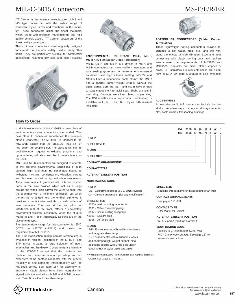
MS-E, MS-F and MS-R are similar to MS-A and
MS-B connectors but have resilient insulators and
wire sealing grommets for extreme environmental
conditions and high altitude sealing. MS-E's and
MS-F's have a mechanical cable clamp; the MS-R
has a shorter, lighter weight endbell without the
cable clamp. Both the MS-F and MS-R have 0 rings
to supplement the interfacial seal. Shells are alumi-
num alloy. Contacts are siliver plated copper alloy.
The F80 modification (crimp contact termination) is
available in E, R, F and BFR styles with resilient
insulators.
In the latest revision of MIL-C-5015, a new class of
environment-resistant connectors was added. This
new class F connector supersedes the previous
class E connector. The MS3106F is identical to the
MS3106E except that the MS3106F has an "0"
ring under the coupling nut. The class E will still be
available upon request for exitsting programs, and
upon ordering will also bear the E nomenclature on
the shell.
MS-F and MS-R connectors are designed to operate
in the extreme environmental conditions of high
altitude filight and must be completely sealed to
withstand moisture, condensation, vibration, corona
and flashover caused by high altitude environments.
They have resilient grommet with internal restric-
tions in the wire cavities which act as 0 rings
around the wires. This allows the wires to slide thru
the grommet with a minimum of friction, yet when
the ferrule is seated and the endbell tightened it
provides a perfect wire seal thru a wide variety of
wire diameters. This seal at the rear, plus the
interfacial seal at the front, effects a completely
environment-resistant asssembly when the plug is
mated to and F or R receptacle. Sockets are of the
closed-entry type.
The temperature range for this connector is -55˚C
(-67˚F) to +125˚C (+257˚F) and meets the
requirements of MIL-C-5015.
The F80 modification (crimp contact termination) is
avialable in resilient insulators in the E, R, F, and
BFR styles, creating a large selection of insert
assemblies and hardware. Components are identical
to the MS-5015 except that the contacts are
modified for crimp termination providing and in-
expensive crimp contact connector with the proven
reliability of and complete intermateability with the
MS-5015 series. See page 187 for assembly in-
structions. Cable clamps have been integrally de-
signed with the endbell on MS-E and MS-F connec-
tors. Class R is without the cable clamp.
POTTING ER CONNECTORS (Solder Contact
Termination)
These lightweight potting connectors provide re-
sistance to salt water, fuels, etc., and will with-
stand the effects of high vibration. 3100 and 3106
connectors with plastic potting cups and resilient
inserts meet the requirements of MS3103 and
MS25183. Contacts are silver plated copper or
brass. ER insulators are resilient; shells are alumi-
num alloy. A 90˚ plug (3108ER) is also available.
ACCESSORIES
Accessories to fit MS connectors include junction
shells, protective caps, dummy or stowage recepta-
cles, cable clamps, telescoping bushings.
PREFIX
CA
MS
3106
3106
R
R20
20
27
27
P
P
W
W
*
-
-
-
PREFIX
MS - Conforms to latest MIL-C-5015 revision
CA - Cannon designation (for any modification)
Coupling thread diameter in sixteenths of an inch
See pages 171-174
P for Pin; S for Socket
W, X, Y and Z (omit for "Normal")
(applies to CA numbers only, not MS)
F80 - Crimp type contacts. See page 187 for
assembly instructions.
3100 - Wall mounting receptacle
3101 - Cable connecting plug
3102 - Box mounting receptacle
3106 - Straight plug
3108 - 90˚ angle plug
E/F - Environmental with resilient insulators
and integral cable clamp.
R - Environmental with resilient insualtors
and shortened light weight endbell; also
additional sealing with 0 ring seal under
coupling nut in styles 3106 and 3108
When ordering MS3106F to the Cannon part number, designate
CA06R. See pages 177 and 181.
*
*
SHELL STYLE
SHELL STYLE
CLASS
CLASS
SHELL SIZE
SHELL SIZE
CONTACT ARRANGEMENT
CONTACT ARRANGEMENTs
CONTACT TYPE
CONTACT TYPE
ALTERNATE INSERT POSITION
ALTERNATE INSERT POSITION
MODIFICATION CODE
MODIFICATION CODE
www.ittcannon.com 168
Dimensions are shown in inches (millimeters).Dimensions subject to change.
MIL-C-5015 Connectors MS-E/F/R/ER
Performance and Material Specifications
High Voltage Cartridges for MS-E and MS-R (HV310*E/R Series)
For class E, R and F connectors, satisfactory mois-
ture sealing will be obtained if AWG and MS wire
sizes and insulation outside diameters are governed
by this table.
Test current ratings of contacts and allowable
voltage drop under test conditions when assembled
as in service are shown below. Maximum total
current to be carried per connector is the same as
the allowable in wire bundles as specified in MIL-
W-5088.
Pin and socket contacts are designed to resist severe vibration and repeated connection and disconnection.
The average force to either engage or separate pin and socket contacts will not exceed the average values
given in the latest revision of MIL-C-5015.
Sizes 12 and 16 contacts, machined from matching thermocouple lead wire alloys, can be supplied in
ITT Cannon connectors. These thermocouple contacs maintain continuity from thermal-sensor leads thru a
bulkhead of other closures in temperature measuring applications.
These contacts for matching lead wires are detailed by the standards of the Instrument Society of America
(I.S.A);
Since the thermocouple connector applications determines the soldering methods and materials to be used,
thermocouple contacts, identified by permanent markings, are normally supplied with untinned solder pots.
Thermocouple contacts are supplied only in connectors having resilient insulators.
MS connectors show no evidence of breakdown when the test voltage given below is applied between the
two closest contacts and between the shell and the contacts closest to the shell for a period of one minute.
MATERIALS AND FINISHES
ELECTRICAL SERVICE DATA
WIRING
CONTACTS
THERMOCOUPLE CONTACTS
HIGH POTENTIAL TEST VOLTAGE
Shell
ContactSize
Test Current(amps)
Potential Drop(millivolts)Contact Size
FORCEIn lbs.
Material
Finish
Aluminum alloy
O.D. Chromate coating
over cadmium plating
Polychloroprene (resilient)
Brass or copper alloy
Silver plate
Tinned solder pot
16
12
8
4
0
16
12
8
4
0
13
23
46
80
150
49
42
26
23
21
Maximum
Average
Minimum
3.00
2.10
.25
J and Y
K
T
Inst.
A
D
E
B
C
* As indicated in previous MS Specification and to be used by designer only as a guide.
Standard contact arrangements are adaptable to
high voltage applications.
Eliminates need for a separate high voltage
connector.
Assembly time is reduced.
•
•
•
1000
2000
2800
3500
4500
7000
250
700
1250
1750
2450
4200
200
500
900
1250
1750
3000
1/16
1/8
3/16
1/4
5/16
1/16
1/8
3/16
1/4
5/16
1
Iron and constantan
Chromel and alumel
Copper and constantan
5.00
3.50
.50
10.00
7.00
.75
15.00
10.50
1.00
20.00
14.00
2.00
16 thru 20
12 thru 14
8 thru 10
4 thru 6
0 thru 2
.064 (1.63) min. to .130 (3.30) max.
.114 (2.90) min. to .170 (4.32) max.
.164 (4.17) min. to .255 (6.48) max.
.275 (6.98) min. to .370 (9.40) max.
.415 (10.54) min. to .550 (13.97) max.
Material
Material
Finish
Termination
I.S.A Standards
MSServiceRating
Suggested *Operating Voltages
DC AC (rms)
TestVoltage(RMS]60 cps
AirSpacing
Nom.(inches)
CreepageDistance
Nom.(inches)
Material
Contact Sizes816 12 4 0
Wire Size(MIL-W-5086)
Insulation OD Limit(inches)
Insulator
Contacts
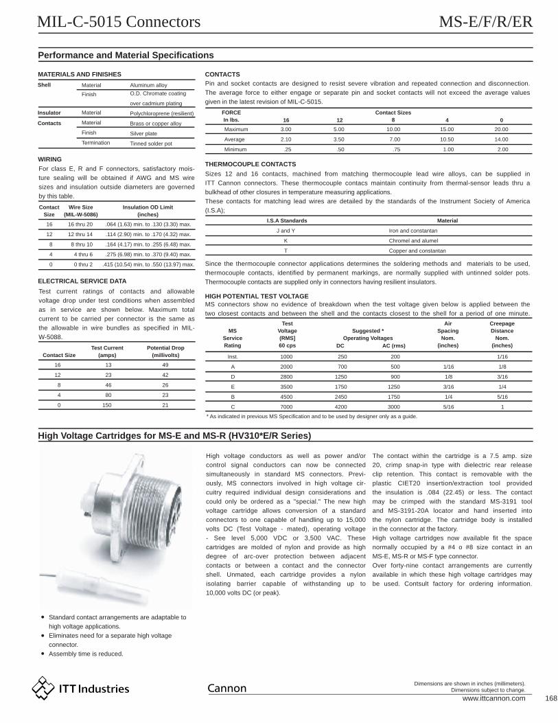
High voltage conductors as well as power and/or
control signal conductors can now be connected
simultaneously in standard MS connectors. Previ-
ously, MS connectors involved in high voltage cir-
cuitry required individual design considerations and
could only be ordered as a "special." The new high
voltage cartridge allows conversion of a standard
connectors to one capable of handling up to 15,000
volts DC (Test Voltage - mated), operating voltage
- See level 5,000 VDC or 3,500 VAC. These
cartridges are molded of nylon and provide as high
degree of arc-over protection between adjacent
contacts or between a contact and the connector
shell. Unmated, each cartridge provides a nylon
isolating barrier capable of withstanding up to
10,000 volts DC (or peak).
The contact within the cartridge is a 7.5 amp. size
20, crimp snap-in type with dielectric rear release
clip retention. This contact is removable with the
plastic CIET20 insertion/extraction tool provided
the insulation is .084 (22.45) or less. The contact
may be crimped with the standard MS-3191 tool
and MS-3191-20A locator and hand inserted into
the nylon cartridge. The cartridge body is installed
in the connector at the factory.
High voltage cartridges now available fit the space
normally occupied by a #4 o #8 size contact in an
MS-E, MS-R or MS-F type connector.
Over forty-nine contact arrangements are currently
available in which these high voltage cartridges may
be used. Contsult factory for ordering information.

www.ittcannon.com 169
Dimensions are shown in inches (millimeters).Dimensions subject to change.
MIL-C-5015 Connectors MS-E/F/R/ER
MS Alternate Insert Positions
Normal Position
ShellSize
A A
AA
AAA
D(G)A(all others)
A
AAA
A(A-L),B(R)D(M-P)
A(C,E,G,J,K,L)B(H,M), D(A,B)
A
AD
E(A)D(all others)
A
Inst. (A,B,h,j)A(all others)
A
D
D
D
A(B,C)D(A)
AA
A
A
A
AD
D (m)A(all others)
A
A
D
A
DA
D
D
EEEBD
A(A-D)D(E)
AA(A-C,E,F)
E(D)D(A)
A(all others)A(C-E)
D(all others)AAA
D(H)A(all others)
D(J)A(all others)
A
DA
D(A,G,H)A(all others)
A
AAA
A
D
DE
Inst.
D)A,E,J)A(all others)
D
D
D
-
AAA
---
-
-
---
-
-
---
-
-
---
-
-70
-145
-215
-290
- - - -
----
9070
-120110
-180145
-240
--
270215
-----
290
35
90-
3535
110
180-
110110
250
270-
250250
325
--
325325
80357090-
-110145180170
-250215270265
280325290
--
70
353580
-70
80
--
8080
--
70
145
110110110
--
110
120170
-110
120120145
215
250250250
--
250
240265
-250
240240215
290
325325280
-290
280
--
280280
--
290
-704580
80
80
8080
90
35
90
-145110110
110
110
-110
180
110
180
-215250250
250
250
-250
270
250
270
-290
-280
280
280
280280
-
325
-
D
DA
A
AInst.Inst.Inst.
AA
A
AA�A�A
ADA�A�A
A(B,C,F,G)Inst.(all others)
DDD
BA
Inst.
AAAA
AAD
DDD
A(C-F)D(A,B,G,H)
Inst.
A
AA
A
A
A
1 #16
1 #162 #163 #16
1 #12
1 #162 #16
1 #8
3 #164 #165 #166 #163 #162 #16
2 #162 #123 #121 #42 #122 #12
7 #162 #163 #163 #165 #16
10 #16
2 #124 #161 #162 #121 #87 #161 #125 #162 #124 #125 #126 #163 #121 #84 #1210 #163 #16
1 #03 #124 #128 #16
4 #162 #83 #122 #87 #127 #162 #121 #165 #126 #163 #123 #8
8S-1 20-22
20-2320-24
20-2720-2920-33
All views are looking into front of pin insert of rear of socket insert.
A B
AB
AB
AB
AB
28-10
28-11
28-1228-1528-1628-17
28-19
28-20
28-2128-22
32-1
32-6
32-7
32-8
32-9
32-15
32-17
36-4
36-536-6
36-7
36-8
36-9
36-1036-14
36-15
40-10
40-56
44-1
48-5
3 #122 #82 #418 #164 #1226 #1635 #1620 #1615 #16
6 #164 #124 #1610 #1637 #163 #163 #4
3 #122 #016 #162 #123 #82 #428 #167 #1224 #166 #1212 #162 #42 #06 #124 #4
3 #0
4 #04 #42 #040 #167 #1246 #161 #1214 #1614 #122 #81 #448 #166 #165 #125 #835 #16
16 #169 #84 #485 #16
36 #166 #12
90 #161 #89 #12
80
80
90808080
80
80
8070
80
80
80
80
80
35
45
70
-35
80
80
80
8090
60
65
72
65
65
110
110
180110110110
110
110
110145
110
110
125
125
110
110
110
145
120110
110
110
125
125180
125
125
144
125
125
250
250
270250250250
250
250
250215
250
250
235
235
250
250
250
215
240250
250
250
235
235270
245
225
216
225
225
280
280
-280280280
280
280
280290
280
280
280
280
280
280
-
290
-325
280
280
280
280-
305
310
288
310
310
3 #163 #82 #82 #162 #814 #1617 #1611 #16
80
3535
3580-
110
110110
110--
250
250250
250--
280
325325
325280-
145110
110
110
-145110110110
110
-110
110
110
110110110-
-
-
215250
250
250
-215250250250
250
-250
250
250
250250250250
250
-
-110110
110
110-110
110
110
110-110
-250250
250
250-250
250
250
250-250
110
110
110110
250
250
250250
290325
325
280
-290325325280
325
280280
280
280
280325--
280
280
280280280
280
325280325
280
280
-280280
280
325
325280
7035
35
80
-70353580
35
8080
80
80
8035-35
80
80
808080
80
358035
80
80
458080
80
35
3580
3 #82 #122 #8 4 #162 #121 #162 #81 #03 #124 #162 #163 #162 #81 #164 #1219 #161 #165 #128 #161 #128 #16
14 #169 #164 #88 #12
8 #161 #87 #12
7 #1216 #168 #12
14 #162 #122 #47 #86 #123 #83 #122 #49 #162 #124 #87 #1624 #16
6 #123 #812 #162 #122 #46 #166 #12
22-222-4
22-5
22-6
22-722-922-1022-1122-12
22-13
22-1422-15
22-17
22-18
22-1922-2022-2222-23
22-27
22-28
24-224-524-6
24-7
24-924-1024-11
24-12
24-20
24-2224-2724-28
28-1
28-2
28-728-9
10S-210SL-410SL-3
12-5
12S-412S-3
14-3
14S-114S-214S-514S-614S-714S-9
16-9
16-1016-1216-1116-13
16S-116S-416S-516S-616S-8
18-1
18-318-418-5
18-718-8
18-9
18-1018-1118-1218-13
18-1518-1918-22
20-220-320-420-7
20-8
20-14
20-1520-16
20-17
20-18
20-19
* Not MSA/B insert arrangements and polarization.
*
*
*
*
*
*
*
*
*
*
*
*
*
*
**
*
*
*
*
*
*
8S 20 28
32
36
40
44
48
22
24
28
10S
12
12S
14
14S
16
16S
18
20
WireSize Service Rating
Alternate Positions-Degrees
W X Y Z
ContactArrange-
mentShellSize
WireSize Service Rating
Alternate Positions-Degrees
W X Y Z
ContactArrange-
mentShellSize
WireSize Service Rating
Alternate Positions-Degrees
W X Y Z
ContactArrange-
ment
Position W Position X Position Y Position Z

2201712
4
98,13
116
22195,315
21181614
www.ittcannon.com 170
Dimensions are shown in inches (millimeters).Dimensions subject to change.
MIL-C-5015 Connectors MS-E/F/R/ER
ITT Cannon Designated Alternate Insert Positions
Not MS approved
NOTE: Front view of pin insulator rotates as shown.
Note: For ITT Cannon contact arrangements not listed, consult factory.
ShellSize
10SL
12S
20
24
32 32A1032A47
36 36A1636A3436A4636A66
40 40A2740A33
10SLA4
12SA10
20A37
24A24
28A16
28A51
54 #16
47 #16
18 #1252 #1627 #1252 #164 #12
60 #167 #86 #4
5 #20
4 #16
4 #8
12 #12
5 #16
4 #4
43 #16
AA
AAAA
2
3
4
5
6
8
9
11
12
13
14
15
16
17
18
19
20
21
22
23
24
25
26
Normal
PositionAngle
(degrees)
0
260
110
80
use pos. 3
85
250
280
105
100
use pos. 8
30
45
120
130
150
195
220
255
290
165
330
235
125
AA
A
Inst.
D
A
A
A
33
3333
143
3
5
4
3
4
44
4445
175
5
8
9
5
5
55
5558
208
8
13
12
8
8
88
8889
2213
12
9
9
99
999
13
13
13
12
1212
12121217
1313
13131318
1520
13
22
2222
42
2
3
2
2
3
28
WireSize
ServiceRating Available Position
ContactArrange-
ment

www.ittcannon.com 171
Dimensions are shown in inches (millimeters).Dimensions subject to change.
MIL-C-5015 Connectors MS-E/F/R/ER
Contact Arrangements (Face View Pin Insert)
LEGENDResilient onlyResilient & Plastic
Shell SizeNo. of ContactsService Rating
8S-11 #16
A
10S-21 #16
A
10SL-42 #16
A
10SL-33 #16
A
10SLA45 #20
A
12S-41 #16
D
12-51 #12
D
12S-32 #16
A
12SA104 #16Inst.
14-31 #8
A
14S-92 #16
A
16-132 #12
(A-IronB-Constantan)
A
16S-42 #16
D
16-112 #12
A
16-121 #4
A
14S-66 #16
Inst.
14S-55 #16
Inst.
14S-24 #16
Inst.
14S-73 #16
A
14S-13 #16
A
16S-53 #16
A
16S-63 #16
A
16-103 #12
A
16-92 #16 (B,D)2 #12 (A,C)
A
16S-85 #16
A
16S-17 #16
A
18-71 #8
B
18-32 #12
D
18-126 #16
A
18-115 #12
A
18-154 #12
(A, C-Iron;B, D-Constantan)
A
18-133 #12 (B,C,C)
1 #8(A)
A
18-104 #12
A
18-44 #16
D
18-223 #16
D
18-51 #16(A)
2 #12(B,C)
D
18-95 #16(B,C,E-G)
2 #12(A,D)Inst.
18-87 #16(A-G)1 #12(H)
A
18-110 #16
A(B,C,F,G)Inst. (all others)
18-1910 #16
A
20-21 #0
D
20-232 #8
A
20-33 #12
D
20-193 #8
A
20-157 #12
A
20-223 #16(B,D,F)3 #8(A,C,E)
A
20-171 #16(F)
5 #12(A-E)A
20-84 #16(B,C,E,F)
2 #8(A,D)Inst.
20-143 #12(C,D,E)
2 #8(A,B)A
20A37ITT Cannon pos.
#8 of 20-4D
20-242 #16 (A,C)2 #8 (B,D)
A
20-44 #12
D
Shell SizeNo. of Contacts
Service Rating
Shell SizeNo. of Contacts
Service Rating
Shell SizeNo. of Contacts
Service Rating
Shell SizeNo. of Contacts
Service Rating
Shell SizeNo. of Contacts
Service Rating
High Volume Layouts - readilyavailable from Cannon Distributors
¢
¢ ¢ ¢ ¢
¢¢¢¢
¢ ¢ ¢
¢
¢ ¢ ¢
A A
A
AA AB
ABA
A
B
BB
BB
BB
B
AA
AA
AA
A
CC
C
C
C
BB
B BB
B
B
BB
B
B
A
AC
C
C C
C
C C
CC
C
C
B
BA
A
A A
A
A
A
AA
A
AC
C
C
DD
D
D DD
DD
DD
D
E
EE F
G
E
F
B
BB
B
B
BB
B
BB
B
B
B
CCC
C
C
C
CC
C
C
C
C
C
G
A
AA
A
A
AAA
A
AAA
A
BB
C
AA
DD
D
DD
D
D
D
D
DD
D
E
E
EEE
E
E
E
EF
F
F
F
G
G
G
G
H
H
H
J
J
I
K
FF
FF
D
E
EF B
D
BC
B
B B
C CD
E
B

www.ittcannon.com 172
Dimensions are shown in inches (millimeters).Dimensions subject to change.
MIL-C-5015 Connectors MS-E/F/R/ER
Contact Arrangements (Continued)
LEGENDResilient onlyResilient & Plastic
Shell SizeNo. of Contacts
Service Rating
20-78 #16
A(C-F)D(A,B,G,H)
20-167 #16(A-G)2 #12(H,I)
A
20-186 #16(A,C-E,G,H)
3 #12(B,F,I)A
20-3311 #16
A
20-1113 #16
Inst.
20-2714 #16
A
20-2917 #16
A
22-71 #0
E
22-123 #16(A,C,D)
2 #8(B,E)D
22-224 #8
A
22-104 #16
E
22-42 #12(A,C)2 #8(B,D)
A
22-93 #12
E
22-61 #16(B)2 #8(A,C)
D
22-23 #8
�D
22-112 #16
B
22-131 #16(E)
4 #12(A-D)A(A-D), D(E)
22-54 #16(A,C,D,F)
2 #12(B,E)D
22-151 #16(D)
5 #12(A-C,E,F)A(A-C,E,F),E(D)
22-287 #12
A
22-188 #16
A(C-E)D(all others)
22-238 #12
D(H)A(all others)
22-178 #16(A-D,F-J)
1 #12(E)D(A), A(all others)
22-209 #16
A
24-107 #8
A
24-27 #12
D
24-123 #12(B,D,E)
2 #4(A,C,)A
24-224 #8
D
24-92 #4
A
22-1419 #16
A
22-1914 #16
A
22-278 #16(A-H)
1 #8(J)D(J), A (all others)
24-277 #16
E
24-68 #12
D(A,G,H)A(all others)
24-116 #12(A-C,G-I)
3 #8(D-F)A
24-209 #16(A-D,G-L)
2 #12(E,F)D
24-1912 #16
6 #12(B-G)A
24A2412 #12
A
24-516 #16
A
24-714 #16(A-M,O)
2 #12(P,N)A
Shell SizeNo. of Contacts
Service Rating
Shell SizeNo. of Contacts
Service Rating
Shell SizeNo. of Contacts
Service Rating
Shell SizeNo. of Contacts
Service Rating
High Volume Layouts - readilyavailable from Cannon Distributors
¢
¢
¢¢
¢ ¢
A
A
A A A AA
AA
AAAAAA
AA
B
B
BBB
B
B
B C
C
CCC
C
CC DDD
DDDD
D
EE
E
EE E
E
EEE
E
EE E
EEE
A A A
A
AA A A
AAAAA
AAA
BB
BB
B
B B
BB
BB
B BB B
BC
C
CC C
C C
CC
C
CC
C
CC
DD
D
D D
D
DD
D
D
DD
D
DD
E EEF
FF
G
G
G
H
H
H
JJ
K
L
M
M
N
N
P P
RS
T
U
V
L
K
J
E
E
F
F
FF
F
F
F
F
F
FFF
FF
FFF
JJ
HH
HH
G
G
G G
G
G
GG
G
G
G
H
H
H
H
H
H
H
I
JJ
J
J
J
J
K
K
K
K
K
L
L
L
LL
M
M
M
M
N
N
N O
P
PS
R
G
G
G
A
A A
A
A A
B
BB
BB
B
BB
B
B
B
B B BB
CC
CC
C
C CC
C
C
C
C
C
C
D
D
D D D
DD
D
D
D
D
E
E
EE
E
E
E
E
F
F
F
F
G
G
G
H H
HJ
J
J
J
K
K
K
L
L
LM
M
M
NN
NP
RS
TF
F F
GG G
H J J M
L
J
K
H
H
H

www.ittcannon.com 173
Dimensions are shown in inches (millimeters).Dimensions subject to change.
MIL-C-5015 Connectors MS-E/F/R/ER
Contact Arrangements (Continued)
LEGENDResilient onlyResilient & Plastic
Shell SizeNo. of Contacts
Service Rating
24-2824 #16
Inst.
28-72 #4
�D
28-223 #16(D-F)3 #4(A-C)
D
28-103 #12(A,F,G)
2 #8(B,E)2 #4(C,D)
D(G), A(all others)
28-16 #12(A,B,D-F,H)
3 #8(C,J,G)
D(A,E,J)A(all others)
28A165 #16(A,D-F,J)4 #4(B,C,G,H)
A
28-196 #16(A-C,H,L,M)
4 #12(E,G,J,K)
A(C,E,G,J,K,L)B(H,M),D(A,B)
28-1226 #16
A
28-1118 #16(A-I, N-X)
4 #12(J-M)A
28-1620 #16
A
28-1715 #16
A(A-L), B(R)D(M-P)
28-204 #16(K-N)
10 #12(A-J,P)A
28-212 #16(A,L,N)
2 #12(M,P)D
28-96 #16(A,H-M)6 #12(B-G)
D
28-1535 #16
AFor MIL equip
design, use 28-21
28-2137 #16
A
28A5143 #16
A
32-174 #4
D
32-13 #12(A,C,D)
2 #0(B,E)E(A),D(all others)
32-152 #0(A,G)
6 #12(B,C,D,E,F,H)D
32-912 #16(C-N)
2 #4(A,B)D
36-43 #0
A(B,C),C(A)
32A1054 #16
A
32A4747 #16
A
32-728 #16(A-N,W-Z,a-k)
7 #12(O-V)
Inst. (A,B,h,j)A(all others)
32-824 #16(A-L,T-Z,a-e)
6 #12(M-S)2 #8(O,R)
AFor new MIL equip.
design, use 32-7
32-616 #16(A-O,S)
2 #12(U,V)3 #8(P,R,T)2 #4(W,X)
A
Shell SizeNo. of Contacts
Service Rating
Shell SizeNo. of Contacts
Service Rating
Shell SizeNo. of Contacts
Service Rating
*NOTE: Additional layouts are the same as shown but in unique alternate positioins. Please consult the factory.
High Volume Layouts - readilyavailable from Cannon Distributors
¢
¢
¢¢
A
A
A
A
B
B
B
BC C
C
D
DD
EE
E
F
FF
G GH J
K L M N P Q
R S T U V
W X Y Z
A
A
A
AA A
A
A
A
A
A A A
B
B
B
BBB
BB
B
B
B BB
C
C
C
CC
C
C
C
C
C
C C
C
D
DD
D
DD
D
DD
D
D
D
E
E
E
EEE
E
E
E
E
E
E
E
F
F
F
F
F F
F
F
F
F
F
F
G
G
G
G
G
G
G
G
G
G
G
GG
H
HH
H
H
H H
H H
H
H H
H
J
J
JI I
J
J
J
J
J
J
JI
JJ
J
K
L
L
L
L
L
L
LL
L L
K
K
K
K
K
K K
K
K
K
L
M
M
M
M
MM M
M
M
M
M
N
N
N
N
N
N
N
N
N
P
P
P
P P
P
P
PP
O
O
Q
R
R
R
R
R
R
R
S
S
S
S
S
S
T
T
T
T
T
T
U
U
U
UU
U
V
V
V
VV
V
W
WW
W
W
X
X
X
X X
Y
Y
Y
Z
Z
a
a
b
b
c
c
d
d
e
e f g h
j kl m
A
A
A
AA
AA
B
B
B
B
B
BB
C
C
C
C
CCC
D
D
D
D
D
D D
EE
EE
EE
F
F
F
F F
G
G
G
G
H
H
H
H
J
J
I
JG H J
L
L
LL
KK
KK
M
M
M M
N
N
N N
P
P
O
O
P P
R
R
RR
SS
SS
T
T
TT
U
U
UU
V
V
V V
W
W
WW
X
X
X
Y
Y
Y
ZZ
ZZ
a
a
a
b
b
b
c
c
a b cc
d
d
dd
e
e
ee
ff
ff
g
g
gg
h
h
hh
j
j
jj
kk
kk
l
ln p r s
m n p q r
s t u v w
x y
A
A
B
B
C
C D E F G
H J
L
K
M N
lm n p r s
t u v w y
m
Z
ab
d

www.ittcannon.com 174
Dimensions are shown in inches (millimeters).Dimensions subject to change.
MIL-C-5015 Connectors MS-E/F/R/ER
Contact Arrangements (Continued)
LEGENDResilient onlyResilient & Plastic
Shell SizeNo. of Contacts
Service Rating
36-54 #0
A
36-64 #4(B,C,E,F)
2 #0(A,D)
A
36-146 #16(K-N,P,Q)
5 #12(B,D,F,H,J)5 #8(A,C,E,G,I)
D
36A1618 #12
(B,C,V,J,K,M,N,R, T-Iron; A,D-F,H,LP,S,U-Constantan)
A
36A4627 #12
A
36-914 #16(A-G,Z-f)14 #12(H-N,S-Y)
2 #8(O,R)1 #4(P)
A
36A6652 #16(A-c,h-AK)
4 #12(d,e,f,g)A
36A3452 #16
A
36-1048 #16
A
36-846 #16(A-X,Z-z
1 #12(Y)A
36-740 #16(A-Z,a-s)
7 #12(t-z)A
36-1535 #16
D(m), A (all others)
40A337 #8(G-N)6 #4(A-F)
A
40-1016 #16(A,B,E-H,M,N,P
Q,V-Y,b,c)9 #8(C,D,I,L,O,R,U,Z,a)
4 #4(K,J,S,T)A
40A2760 #16
A
40-5685 #16
A
48-590 #16(A-BL,BN-BT,BW,BX)
1 #8(CD)9 #12(BM,BU,BV,BY-CC,CE)
A
44-136 #16(A-S,Z-t
6 #12(T-Y)
D
Shell SizeNo. of Contacts
Service Rating
Shell SizeNo. of Contacts
Service Rating
Shell SizeNo. of Contacts
Service Rating
High Volume Layouts - readilyavailable from Cannon Distributors
Grommet not available. Consultfactory for ordering connectorswith this arrangment.
¢
¢
†
†
A
B C D E F G
H J K L M N P Q R
S T U V W X Y Z a b
c d e f g h j k m n p
q
AA AB AC AD AE AF AG AH AJ AK AL
AM AN AP AQ AR AS AT AU AV AW
AX AY AZ BA BB BC BD BE BF BG
BH BJ BK BL
BMBM BP BQ BR
BSBU BV
BW BXBT
BZ
BY
CCCD
CA
CB
CE
AA AB
AC AD AE AF AG AJ AK AL AM AN
AP AR AS AT AU AV AW AX AY
AZ BA BB BC BD BE BF BG
BJ BK BL BNBM BP BR
BS BU BVBT
r s t u v w x y z
A124
2322
21
20
19
18
1716
1514
35
50
59
60
54
4241
53
52
51
36
40
39
38
37
25
43
55
58
49
34
13
2
26
44
56
57
48
33
12
34
2827
45
46
47
32
11
29
30
31
10
5
6
7
8
98
A
A
BB
B
C
C
C
D
D
D
E
E
E
F
F
F
G
G
H
H
H
J
J
JI
K
K
K
L
L
L
M
M
M
N
N
ON
P
P
R
R
S
S
T
T
U
U
V
V
W
W
X
X
Y
Y
Z
Z
a
a
b
b
c
c
d
d e
f
f
g
g
h i
h
j
j
k
k
m
m
n
n
o
p
p
q r
r
s
s
t
t
u v w x y z
AAA A
A
A
AAA
AAA
B
B
B
B
B
B
BBB
BB
C
C
C
C
C
C
CC
CCC
C
D
D
D
D
DD
DDDD
D
D
E
E
E
E
E
EEE
E
E
E
F
F
F
F
F
FFFFF
F
G
G
G
G
GG
G
G
G
H
H
H
H
H
HHHH
H
J
J
J
J
JJ
JJ
J
J
II
I
I
I
K
K
K
K
KKK
KK
K
LL
L
L
LL
LLL
L
M
M
M
M
MMM
MM
M
N N
N
N
NN
N
NN
N
O
OOO
P
P
P
PP
PPPP
Q
Q
Q
R
R
R
RR
RRR
R
S
S
S
SS
SS
S
S
T
T
T
TT
TT
T
T
U
U
U
UUU
UU
U
V
V
VV
V
VVV
W
W
WW
WW
W
W
X
X
XX
XX
X
X
Y
Y
YY
YYY
Y
Z
Z
ZZ
ZZZ
Z
a
a
a
aaaa
a
b b
bb
bb
b
b
c c
cc
cc
c
c
d
d
dd
ddd
d
e
e
e
eee
e
f
ff
ff
ff g
ggg
gg
hh
hhhh l
iii
jj
jj
j
kkkkk
k
mm
mm
m
m
nn
nnn
pp
ppp
rrr
r
r
ssss
s
tt
t
t
t
uu
uu
u vvvv
v wwww
w xxx
xx
yy
yy
zz AA AA
AB AB
AK AJ AM
AD ADAE AEAF AFAGAG
AC AC
zz
z
†

www.ittcannon.com 175
Dimensions are shown in inches (millimeters).Dimensions subject to change.
MIL-C-5015 Connectors MS-E/F/R/ER
Cable Connecting Plug (Receptacle with no mounting flange)
MS3101E/MS3101FIntegral Cable Clamp
CA3101E/CA3101E MS3101E cable connecting
plugs are used for cable
extension requirements, where
mounting provisions are
unnecessary.
MS3101E plugs mate with
3106, 3107 and 3108 plugs.
Note: the D revision of
MIL-C-5015 has changed the
nomenclature of the 3101 from
receptacle to plug.
MS3101R cable connecting plug
is identical in purpose to the
MS3101E. The MS3101R
features a shorter lightweight
endbell and mates with 3106,
3107 and 3108 plugs. Note:
The D revision of the
MIL-C-5015 specification has
changed the nomenclature of
the 3101 from receptacle to
plug.
MS3101R
ShellSize
ShellSize
†Not to MS specification*Not Available in MS3101E and MS3101R.
Performance Specifications - Page 168
Contact, Sealing Plugs, Assembly Tools - Page
187
Contact Arrangements - Page 171-174
8S
10S
10SL
12S
14S
16S
12
14
1/2-28UNEF-2A
5/8-24UNEF-2A
5/8-24UNEF-2A
3/4-20UNEF-2A
7/8-20UNEF-2A
1-20UNEF-2A
3/4-20UNEF-2A
7/8-20UNEF-2A
1-20UNEF-2A
1-1/8-18UNEF-2A
1-1/4-18UNEF-2A
1-3/8-18UNEF-2A
1-1/2-18UNEF-2A
1-3/4-18UNS-2A
2-18UNS-2A
2-1/4-16UN-2A
2-1/2-16UN-2A
16
18
20
22
24
28
32
36
40
ShellSize
AThread
AThread
8S
10S
10SL
12S
14S
16S
12
14
16
18
20
22
24
28
32
36
40
.375 (9.53)
.375 (9.53)
.375 (9.53)
.375 (9.53)
.375 (9.53)
.375 (9.53)
.625(15.88)
.625(15.88)
.625(15.88)
.625(15.88)
.625(15.88)
.625(15.88)
.625(15.88)
.625(15.88)
.625(15.88)
.625(15.88)
.625(15.88)
.235 (5.97)
.235 (5.97)
.297 (7.54)
.297 (7.54)
.422 (10.72)
.547 (13.89)
.297 (7.54)
.422 (10.72)
.547 (13.89)
.610 (15.49)
.735 (18.67)
.740 (18.80)
.922 (23.42)
.922 (23.42)
1.235 (31.37)
1.360 (34.54)
1.628 (41.35)
.102 (2.59)
.102 (2.59)
.140 (3.56)
.140 (3.56)
.195 (4.95)
.255 (6.48)
.140 (3.56)
.195 (4.95)
.255 (6.48)
.285 (7.24)
.350 (8.89)
.350 (8.89)
.468 (11.89)
.468 (11.89)
.664 (15.87)
.694 (17.63)
.911 (23.14)
.844 (21.44)
.969 (24.61)
1.062 (26.97)
1.062 (26.97)
1.156 (29.36)
1.281 (32.54)
1.062 (26.97)
1.156 (29.36)
1.281 (32.54)
1.344 (34.14)
1.500 (38.10)
1.625 (41.28)
1.750 (44.45)
2.000 (50.80)
2.250 (57.15)
2.500 (63.50)
2.750 (69.85)
.125 (3.18)
.125 (3.18)
.125 (3.18)
.140 (3.56)
.140 (3.56)
.140 (3.56)
.146 (3.71)
.146 (3.71)
.146 (3.71)
.180 (4.57)
.180 (4.57)
.180 (4.57)
.203 (5.16)
.203 (5.16)
.203 (5.16)
.203 (5.16)
.203 (5.16)
2.250 (57.15)
2.250 (57.15)
2.250 (57.15)
2.250 (57.15)
2.250 (57.15)
2.250 (57.15)
2.625 (66.68)
2.625 (66.58)
2.625 (66.58)
2.688 (68.28)
2.750 (69.85)
2.750 (69.85)
2.969 (75.44)
3.031 (76.99)
3.031 (76.99)
3.281 (83.34)
3.560 (89.66)†
1.838 (46.69)
1.838 (46.69)
1.838 (46.69)
1.838 (46.69)
1.838 (46.69)
1.838 (46.69)
2.181 (55.40)
2.181 (55.40)
2.181 (55.40)
2.281 (55.40)
2.281 (55.40)
2.281 (55.40)
2.281 (55.40)
2.281 (55.40)
2.322 (58.98)
2.322 (58.98)
2.427 (61.65)†
.562 (14.27)
.562 (14.27)
.562 (14.27)
.562 (14.27)
.562 (14.27)
.562 (14.27)
.750 (19.05)
.750 (19.05)
.750 (19.05)
.750 (19.05)
.750 (19.05)
.750 (19.05)
.812 (20.62)
.812 (20.62)
.875 (22.23)
.875 (22.23)
.875 (22.23)
.890 (22.61)
.890 (22.61)
.970 (24.64)
.970 (24.64)
1.150 (29.21)
1.250 (31.75)
.970 (24.64)
1.150 (29.21)
1.250 (31.75)
1.450 (36.83)
1.570 (39.88)
1.570 (39.88)
1.880 (47.75)
1.880 (47.75)
2.205 (56.01)
2.400 (60.96)
2.840 (72.14)
.515 (13.08)
.640 (16.26)
.640 (16.26)
.765 (19.43)
.890 (22.61)
1.015 (25.78)
.765 (19.43)
.890 (22.61)
1.015 (25.78)
1.140 (28.96)
1.265 (32.13)
1.390 (35.31)
1.515 (38.48)
1.765 (44.83)
2.015 (51.18)
2.270 (57.66)
2.427 (61.65)
.840 (21.34)
.840 (21.34)
.900 (22.86)
.900 (22.86)
1.00 (27.94)
1.200 (30.48)
.900 (22.86)
1.100 (27.94)
1.200 (30.48)
1.300 (33.02)
1.500 (38.10)
1.500 (38.10)
1.740 (44.20)
1.740 (44.20)
2.075 (52.71)
2.300 (58.42)
2.688 (68.28)
1.046 (26.57)
1.046 (26.57)
1.125 (28.58)
1.125 (28.58)
1.343 (34.11)
1.484 (37.69)
1.125 (28.58)
1.343 (34.11)
1.484 (37.69)
1.609 (40.87)
1.890 (48.01)
1.890 (48.01)
2.170 (55.12)
2.170 (55.12)
2.656 (67.46)
2.922 (74.22)
-*
BMin.
EMax.
EMin.
GMax.
KMax.
LMax.
LMax.
1 1PMax.
SMax.
VMax.
WMax.
M+.031(0.79)-.000(0.00)
CA3101R
W
G
G
S 1
S 1
P
P
V
A Thd.
A Thd.
B
B
M
M
L
1L
K
K
E

www.ittcannon.com 176
Dimensions are shown in inches (millimeters).Dimensions subject to change.
MIL-C-5015 Connectors MS-E/F/R/ER
Wall Mounting Receptacle
MS3100E/MS3100FIntegral Cable Clamp
CA3100E/CA3100E MS3100F wall mounting
receptacles are used to carry
wires thru walls or bulkheads,
or to provide a means of
disconnection at a bulkhead.
MS3100F receptacles mate
with 3106 and 3108 plugs.
MS3100E is identical to
MS3100F and is available upon
request. For new equipment,
customer should specify
MS3100F.
The MS3100R receptacle is
identical in purpose to the
MS3100F. The MS3100R
features a shorter light weight
endbell and mates with 3106
and3108 plugs.
MS3100R
ShellSize
ShellSize
†Not to MS specification*Not Available in MS3101E and MS3101R.
Performance Specifications - Page 168
Contact, Sealing Plugs, Assembly Tools - Page
187
Contact Arrangements - Page 171-174
8S
10S
10SL
12S
14S
16S
12
14
1/2-28UNEF-2A
5/8-24UNEF-2A
5/8-24UNEF-2A
3/4-20UNEF-2A
7/8-20UNEF-2A
1-20UNEF-2A
3/4-20UNEF-2A
7/8-20UNEF-2A
1-20UNEF-2A
1-1/8-18UNEF-2A
1-1/4-18UNEF-2A
1-3/8-18UNEF-2A
1-1/2-18UNEF-2A
1-3/4-18UNS-2A
2-18UNS-2A
2-1/4-16UN-2A
2-1/2-16UN-2A
16
18
20
22
24
28
32
36
40
ShellSize
AThread
AThread
8S
10S
10SL
12S
14S
16S
12
14
16
18
20
22
24
28
32
36
40
.375 (9.53)
.375 (9.53)
.375 (9.53)
.375 (9.53)
.375 (9.53)
.375 (9.53)
.625(15.88)
.625(15.88)
.625(15.88)
.625(15.88)
.625(15.88)
.625(15.88)
.625(15.88)
.625(15.88)
.625(15.88)
.625(15.88)
.625(15.88)
.235 (5.97)
.235 (5.97)
.297 (7.54)
.297 (7.54)
.422 (10.72)
.547 (13.89)
.297 (7.54)
.422 (10.72)
.547 (13.89)
.610 (15.49)
.735 (18.67)
.740 (18.80)
.922 (23.42)
.922 (23.42)
1.235 (31.37)
1.360 (34.54)
1.628 (41.35)
.102 (2.59)
.102 (2.59)
.140 (3.56)
.140 (3.56)
.195 (4.95)
.255 (6.48)
.140 (3.56)
.195 (4.95)
.255 (6.48)
.285 (7.24)
.350 (8.89)
.350 (8.89)
.468 (11.89)
.468 (11.89)
.664 (15.87)
.694 (17.63)
.911 (23.14)
.125 (3.18)
.125 (3.18)
.125 (3.18)
.140 (3.56)
.140 (3.56)
.140 (3.56)
.146 (3.71)
.146 (3.71)
.146 (3.71)
.180 (4.57)
.180 (4.57)
.180 (4.57)
.203 (5.16)
.203 (5.16)
.203 (5.16)
.203 (5.16)
.203 (5.16)
2.250 (57.15)
2.250 (57.15)
2.250 (57.15)
2.250 (57.15)
2.250 (57.15)
2.250 (57.15)
2.625 (66.68)
2.625 (66.58)
2.625 (66.58)
2.688 (68.28)
2.750 (69.85)
2.750 (69.85)
2.969 (75.44)
3.031 (76.99)
3.031 (76.99)
3.281 (83.34)
3.560 (89.66)†
1.838 (46.69)
1.838 (46.69)
1.838 (46.69)
1.838 (46.69)
1.838 (46.69)
1.838 (46.69)
2.181 (55.40)
2.181 (55.40)
2.181 (55.40)
2.281 (55.40)
2.281 (55.40)
2.281 (55.40)
2.281 (55.40)
2.281 (55.40)
2.322 (58.98)
2.322 (58.98)
2.427 (61.65)†
.562 (14.27)
.562 (14.27)
.562 (14.27)
.562 (14.27)
.562 (14.27)
.562 (14.27)
.750 (19.05)
.750 (19.05)
.750 (19.05)
.750 (19.05)
.750 (19.05)
.750 (19.05)
.812 (20.62)
.812 (20.62)
.875 (22.23)
.875 (22.23)
.875 (22.23)
.890 (22.61)
.890 (22.61)
.970 (24.64)
.970 (24.64)
1.150 (29.21)
1.250 (31.75)
.970 (24.64)
1.150 (29.21)
1.250 (31.75)
1.450 (36.83)
1.570 (39.88)
1.570 (39.88)
1.880 (47.75)
1.880 (47.75)
2.205 (56.01)
2.400 (60.96)
2.840 (72.14)
.594 (15.09)
.719 (18.26)
.719 (18.26)
.812 (20.62)
.906 (23.01)
.969 (24.61)
.812 (20.62)
.906 (23.01)
.969 (24.61)
1.062 (26.97)
1.156 (29.36)
1.250 (31.75)
1.375 (34.93)
1.562 (39.67)
1.750 (44.45)
1.938 (49.23)
2.188 (55.58)
.875 (22.23)
1.000 (25.40)
1.000 (25.40)
1.094 (27.79)
1.188 (30.18)
1.281 (32.54)
1.094 (27.79)
1.188 (30.18)
1.281 (32.54)
1.375 (34.93)
1.500 (38.10)
1.625 (41.28)
1.750 (44.45)
2.000 (50.80)
2.250 (57.15)
2.500 (63.50)
2.750 (69.85)
.120 (3.05)
.120 (3.05)
.120 (3.05)
.120 (3.05)
.120 (3.05)
.120 (3.05)
.120 (3.05)
.120 (3.05)
.120 (3.05)
.120 (3.05)
.120 (3.05)
.120 (3.05)
.147 (3.73)
.147 (3.73)
.173 (4.39)
.173 (4.39)
.173 (4.39)
.840 (21.34)
.840 (21.34)
.900 (22.86)
.900 (22.86)
1.100 (27.94)
1.200 (30.48)
.900 (22.86)
1.100 (27.94)
1.200 (30.48)
1.300 (33.02)
1.500 (38.10)
1.500 (38.10)
1.740 (44.20)
1.740 (44.20)
2.075 (52.71)
2.300 (58.42)
2.688 (68.28)
1.046 (26.57)
1.046 (26.57)
1.125 (28.58)
1.125 (28.58)
1.343 (34.11)
1.484 (37.69)
1.125 (28.58)
1.343 (34.11)
1.484 (37.69)
1.609 (40.87)
1.890 (48.01)
1.890 (48.01)
2.170 (55.12)
2.170 (55.12)
2.656 (67.46)
2.922 (74.22)
-*
BMin.
EMax.
EMin.
KMax.
LMax.
LMax.
1 PMax.
S+_.031
R+_.005
VMax.
WMax.
M+.031-.000
T+.010-.005
CA3100R
W
P
V
A Thd.
T Dia.4 Mtg. Holes
T Dia.4 Mtg. Holes
STyp.
RTyp.
R Typ.
S Typ.
A Thd.
B
B
M
M
L
1L
K
K
E

www.ittcannon.com 177
Dimensions are shown in inches (millimeters).Dimensions subject to change.
MIL-C-5015 Connectors MS-E/F/R/ER
Straight Plug
MS3106E/MS3106FIntegral Cable Clamp
CA3106E/CA06R MS3106F straight plugs mate
with 3100 and 3102
receptacles and 3101 plugs.
The MS3106E is available upon
request. For new equipment,
customer should specify.
MS3106F. MS3106E is identical
to MS3106F except to O ring
under the coupling nut.
The MS3106R striaght plug is
identical in puropse to the
MS3106F. The MS3106R has
the shorter endbell. This plug
will mate with 3100 and 3102
receptacles and 3101 plugs.
MS3106R
ShellSize
ShellSize
†Not to MS specification
Performance Specifications - Page 168
Contact, Sealing Plugs, Assembly Tools - Page
187
Contact Arrangements - Page 171-174
8S
10S
10SL
12S
14S
16S
12
14
1/2-28UNEF-2B
5/8-24UNEF-2B
5/8-24UNEF-2B
3/4-20UNEF-2B
7/8-20UNEF-2B
1-20UNEF-2B
3/4-20UNEF-2B
7/8-20UNEF-2B
1-20UNEF-2B
1-1/8-18UNEF-2B
1-1/4-18UNEF-2B
1-3/8-18UNEF-2B
1-1/2-18UNEF-2B
1-3/4-18UNS-2B
2-18UNS-2B
2-1/4-16UN-2B
2-1/2-16UN-2B
16
18
20
22
24
28
32
36
40
ShellSize
AThread
AThread
** Barrel engaging face to shoulder.
8S
10S
10SL
12S
14S
16S
12
14
16
18
20
22
24
28
32
36
40
.235 (5.97)
.235 (5.97)
.297 (7.54)
.297 (7.54)
.422 (10.72)
.547 (13.89)
.297 (7.54)
.422 (10.72)
.547 (13.89)
.610 (15.49)
.735 (18.67)
.740 (18.80)
.922 (23.42)
.922 (23.42)
1.235 (31.37)
1.360 (34.54)
1.628 (41.35)
.102 (2.59)
.102 (2.59)
.140 (3.56)
.140 (3.56)
.195 (4.95)
.255 (6.48)
.140 (3.56)
.195 (4.95)
.255 (6.48)
.285 (7.24)
.350 (8.89)
.350 (8.89)
.468 (11.89)
.468 (11.89)
.664 (15.87)
.694 (17.63)
.911 (23.14)
.536 (13.61)
.536 (13.61)
.536 (13.61)
.536 (13.61)
.536 (13.61)
.536 (13.61)
.724 (18.39)
.724 (18.39)
.724 (18.39)
.724 (18.39)
.724 (18.39)
.724 (18.39)
.724 (18.39)
.724 (18.39)
.724 (18.39)
.724 (18.39)
.724 (18.39)
.844 (21.44)
.969 (24.61)
.969 (24.61)
1.062 (26.97)
1.156 (29.36)
1.250 (31.75)
1.062 (26.97)
1.156 (29.36)
1.250 (31.75)
1.344 (34.14)
1.469 (37.31)
1.594 (40.49)
1.719 (43.66)
1.969 (50.01)
2.219 (56.36)
2.469 (62.71)
2.723 (69.16)†
2.250 (57.15)
2.250 (57.15)
2.250 (57.15)
2.250 (57.15)
2.250 (57.15)
2.250 (57.15)
2.625 (66.68)
2.625 (66.68)
2.625 (66.68)
2.688 (68.28)
2.750 (69.85)
2.750 (69.85)
2.969 (75.41)
3.031 (76.99)
3.031 (76.99)
3.281 (83.34)
3.560 (89.66)†
1.838 (46.69)
1.838 (46.69)
1.838 (46.69)
1.838 (46.69)
1.838 (46.69)
1.838 (46.69)
2.181 (55.40)
2.181 (55.40)
2.181 (55.40)
2.281 (55.40)
2.281 (55.40)
2.281 (55.40)
2.281 (55.40)
2.281 (55.40)
2.322 (58.98)
2.322 (58.98)
2.427 (61.65)†
.890 (22.61)
.890 (22.61)
.970 (24.64)
.970 (24.64)
1.150 (29.21)
1.250 (31.75)
.970 (24.64)
1.150 (29.21)
1.250 (31.75)
1.450 (36.83)
1.570 (39.88)
1.570 (39.88)
1.880 (47.75)
1.880 (47.75)
2.205 (56.01)
2.400 (60.96)
2.840 (72.14)
.840 (21.34)
.840 (21.34)
.900 (22.86)
.900 (22.86)
1.00 (27.94)
1.200 (30.48)
.900 (22.86)
1.100 (27.94)
1.200 (30.48)
1.300 (33.02)
1.500 (38.10)
1.500 (38.10)
1.740 (44.20)
1.740 (44.20)
2.075 (52.71)
2.300 (58.42)
2.688 (68.28)
1.046 (26.57)
1.046 (26.57)
1.125 (28.58)
1.125 (28.58)
1.343 (34.11)
1.484 (37.69)
1.125 (28.58)
1.343 (34.11)
1.484 (37.69)
1.609 (40.87)
1.890 (48.01)
1.890 (48.01)
2.170 (55.12)
2.170 (55.12)
2.656 (67.46)
2.922 (74.22)
-*
EMax.
EMin.
J**Max.
LMax.
NMax.
LMax.
1 P Max.
1 VMax.
WMax.
CA3106R
WA Thd.
V
N
J**
A
J**
L
1L1P
1PE
www.ittcannon.com 178
Dimensions are shown in inches (millimeters).Dimensions subject to change.
MIL-C-5015 Connectors MS-E/F/R/ER
Box Mounting Receptacle
90˚ Angle Plug
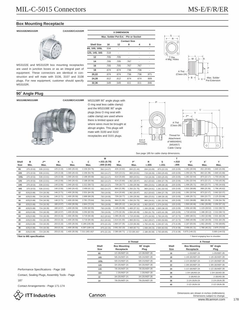
MS3102E/MS3102R CA3102E/CA3102R
MS3108R 90˚ angle plugs with
O ring seal less cable clamp)
and the MS3108E 90˚ angle
plugs (less O ring seal with
cable clamp) are used where
there is limited space and
where wires must be brought at
abrupt angles. This plugs will
mate with 3100 and 3102
receptacles and 3101 plugs.
MS3108E/MS3108R
ShellSize
ShellSize
†Not to MS specification
Performance Specifications - Page 168
Contact, Sealing Plugs, Assembly Tools - Page
187
Contact Arrangements - Page 171-174
8S
10S
10SL
12S
14S
16S
12
14
X DIMENSION
Shell Size
Contact Size
16 12 8 04
Max. Solder Pot Ext. - Pin or Socket
8S, 10S, 10SL
12S, 14S, 16S
12
14
16
18
20,22
24,28
32,36
.534
.518
.705
.705
.705
.674
.674
.612
.549
-
-
.705
.705
.705
.674
.674
.612
.549
-
-
-
.767
.767
.736
.736
.674
.611
-
-
-
-
.767
.736
.736
.674
.611
-
-
-
-
-
-
.971
.909
.846
1/2-28UNEF-2B
5/8-24UNEF-2B
5/8-24UNEF-2B
3/4-20UNEF-2B
7/8-20UNEF-2B
1-20UNEF-2B
3/4-20UNEF-2B
7/8-20UNEF-2B
1/2-28UNEF-2A
5/8-24UNEF-2A
5/8-24UNEF-2A
3/4-20UNEF-2A
7/8-20UNEF-2A
1-20UNEF-2A
3/4-20UNEF-2A
7/8-20UNEF-2A
1-20UNEF-2B
1-1/8-18UNEF-2B
1-1/4-18UNEF-2B
1-3/8-18UNEF-2B
1-1/2-18UNEF-2B
1-3/4-18UNS-2B
2-18UNS-2B
2-1/4-16UN-2B
2-1/2-16UN-2B
1-20UNEF-2A
1-1/8-18UNEF-2A
1-1/4-18UNEF-2A
1-3/8-18UNEF-2A
1-1/2-18UNEF-2A
1-3/4-18UNS-2A
2-18UNS-2A
2-1/4-16UN-2A
2-1/2-16UN-2A
16
18
20
22
24
28
32
36
40
ShellSize
Box MountingReceptacle
Box MountingReceptacle
90˚ AnglePlug
90˚ AnglePlug
A ThreadA Thread
** Barrel engaging face to shoulder.
8S
10S
10SL
12S
14S
16S
12
14
16
18
20
22
24
28
32
36
40
.536 (13.61)
.536 (13.61)
.536 (13.61)
.536 (13.61)
.536 (13.61)
.536 (13.61)
.724 (18.39)
.724 (18.39)
.724 (18.39)
.724 (18.39)
.724 (18.39)
.724 (18.39)
.724 (18.39)
.724 (18.39)
.724 (18.39)
.724 (18.39)
.724 (18.39)
.844 (21.44)
.969 (24.61)
.969 (24.61)
1.062 (26.97)
1.156 (29.36)
1.250 (31.75)
1.062 (26.97)
1.156 (29.36)
1.250 (31.75)
1.344 (34.14)
1.469 (37.31)
1.594 (40.49)
1.719 (43.66)
1.969 (50.01)
2.219 (56.36)
2.469 (62.71)
2.723 (69.16)†
BMin.
KMax.
J**Max.
LMax.
M+.031 (0.79)-.000 (0.00)
T+.010-.005
PMax.
R+_.005
S+_.031
LMax.
3 P Max.
1 1VMax.
1XMax.
YMax.
CA3108E/CA3108R
J**
A Thd.(Class-2B)
End ofThread
(MS3108R)
See page 185 for cable clamp dimensions.
Thread forAttachment
of M85049/41(MS3057)
Cable Clamp
Y
LM K
P
XB
T Dia.4 Mtg. Holes
A Thd.(Class-2A)
Max. SolderPot Extension
RS
3L
1V
1P
1X
.375 (9.53)
.375 (9.53)
.375 (9.53)
.375 (9.53)
.375 (9.53)
.375 (9.53)
.625(15.88)
.625(15.88)
.625(15.88)
.625(15.88)
.625(15.88)
.625(15.88)
.625(15.88)
.625(15.88)
.625(15.88)
.625(15.88)
.625(15.88)
.125 (3.18)
.125 (3.18)
.125 (3.18)
.140 (3.56)
.140 (3.56)
.140 (3.56)
.146 (3.71)
.146 (3.71)
.146 (3.71)
.180 (4.57)
.180 (4.57)
.180 (4.57)
.203 (5.16)
.203 (5.16)
.203 (5.16)
.203 (5.16)
.203 (5.16)
1.040 (26.42)
1.040 (26.42)
1.040 (26.42)
1.040 (26.42)
1.040 (26.42)
1.040 (26.42)
1.400 (35.56)
1.400 (35.56)
1.400 (35.56)
1.400 (35.56)
1.400 (35.56)
1.400 (35.56)
1.400 (35.56)
1.400 (35.56)
1.400 (35.56)
1.400 (35.56)
1.400 (35.56)
2.156 (54.76)
2.156 (54.76)
2.188 (55.58)
2.188 (55.58)
2.312 (58.72)
2.406 (61.11)
2.531 (64.29)
2.688 (68.28)
2.781 (70.64)
2.844 (72.24)
3.250 (82.55)
3.250 (82.55)
3.719 (94.46)
3.719 (94.46)
4.188 (106.38)
4.297 (109.14)
7.211 (183.16)†
.426 (10.82)
.520 (13.21)
.614 (15.60)
.614 (15.60)
.739 (18.77)
.864 (21.95)
.614 (15.60)
.739 (18.77)
.864 (21.95)
.989 (25.12)
1.145 (29.08)
1.270 (32.26)
1.395 (35.43)
1.614 (41.00)
1.864 (47.35)
2.051 (52.10)
2.390 (60.71)
1.281 (30.94)
1.250 (31.75)
1.281 (32.54)
1.281 (32.54)
1.406 (35.71)
1.531 (38.89)
1.281 (32.54)
1.406 (35.71)
1.531 (38.89)
1.593 (40.46)
1.656 (42.06)
1.718 (43.64)
1.890 (48.01)
1.968 (49.99)
2.187 (55.55)
2.406 (61.11)
5.875 (149.22)
.811 (20.60)
.842 (21.39)
.873 (22.17)
.873 (22.17)
.936 (23.77)
.998 (25.35)
.873 (22.17)
.936 (23.77)
.998 (25.35)
1.061 (26.95)
1.123 (28.52)
1.186 (30.12)
1.263 (32.08)
1.342 (34.09)
1.561 (39.65)
1.780 (45.21)
-
1.640 (41.66)
1.640 (41.66)
1.703 (43.26)
1.703 (43.26)
1.765 (44.83)
1.796 (45.62)
2.062 (52.37)
2.125 (53.98)
2.156 (54.76)
2.250 (57.15)
2.312 (58.72)
2.312 (58.72)
2.531 (64.29)
2.531 (64.29)
2.750 (69.85)
2.875 (73.02)
5.690 (144.53)
.562 (14.27)
.562 (14.27)
.562 (14.27)
.562 (14.27)
.562 (14.27)
.562 (14.27)
.750 (19.05)
.750 (19.05)
.750 (19.05)
.750 (19.05)
.750 (19.05)
.750 (19.05)
.812 (20.62)
.812 (20.62)
.875 (22.23)
.875 (22.23)
.875 (22.23)
.594 (15.09)
.719 (18.26)
.719 (18.26)
.812 (20.62)
.906 (23.01)
.969 (24.61)
.812 (20.62)
.906 (23.01)
.969 (24.61)
1.062 (26.97)
1.156 (29.36)
1.250 (31.75)
1.375 (34.93)
1.562 (39.67)
1.750 (44.45)
1.938 (49.23)
2.188 (55.58)
.875 (22.23)
1.000 (25.40)
1.000 (25.40)
1.094 (27.79)
1.188 (30.18)
1.281 (32.54)
1.094 (27.79)
1.188 (30.18)
1.281 (32.54)
1.375 (34.93)
1.500 (38.10)
1.625 (41.28)
1.750 (44.45)
2.000 (50.80)
2.250 (57.15)
2.500 (63.50)
2.750 (69.85)
.120 (3.05)
.120 (3.05)
.120 (3.05)
.120 (3.05)
.120 (3.05)
.120 (3.05)
.120 (3.05)
.120 (3.05)
.120 (3.05)
.120 (3.05)
.120 (3.05)
.120 (3.05)
.147 (3.73)
.147 (3.73)
.173 (4.39)
.173 (4.39)
.173 (4.39)
MS3102E and MS3102R box mounting receptacles
are used in junction boxes or as an integral part of
equipment. These connectors are identical in con-
struction and will mate with 3106, 3107 and 3108
plugs. For new equipment, customer should specify
MS3102R.

www.ittcannon.com 179
Dimensions are shown in inches (millimeters).Dimensions subject to change.
MIL-C-5015 Connectors MS-E/F/R/ER
How to Order
Wall Mounting Receptacle
MS3103Nylon Potting CupThreaded Attachment Ring
CA3100ER
PREFIX
PREFIX
CA - ITT Cannon prefix indicating special applica-
tion or variation of MS
The CA3100ER receptacle (MS3103) is supplied with a resilient insulator and nylon potting cup with a
threaded attachment ring. This receptacle mates with 3106, 3107, and 3108 plugs.
S
R PolarizingBoss
T Dia.4 Mtg. Holes A Thd.
L
Coupling thread diameter figured in sixteenths of
an inch
See pages 171-174
P for Pin: S for Socket
3100 - Wall mounting receptacle (MS3103)
3106 - Straight plug (MS25183)
3108 - 90˚ angle plug
ER - Resilient insulator, nylon potting cup and
thread attachment ring
No class designator for MS types.
SHELL STYLE
SHELL STYLE
MS
MS
CA
25183
3103
3100
-
-
ER
18
18
18
10
10
10
P
P
P
-
-
-
COTNACT ARRANGEMENTS
COTNACT TYPE
SHELL STYLE
CLASS
CLASS
SHELL SIZE
CONTACT ARRANGEMENT
CONTACT TYPE
ShellSize
Performance Specifications - Page 168
Contact, Sealing Plugs, Assembly Tools - Page
187
Contact Arrangements - Page 171-174
8S
10S
10SL
12S
14S
16S
12
14
16
18
20
22
24
28
32
36
LMax.
R+_.005 (+_0.13)
R+.010 (+0.25)-.005 (+0.13)
SMax.
AThread
.594 (15.09)
.719 (18.26)
.719 (18.26)
.812 (20.62)
.906 (23.01)
.969 (24.61)
.812 (20.62)
.906 (23.01)
.968 (24.59)
1.062 (26.97)
1.156 (29.36)
1.250 (31.75)
1.375 (34.92)
1.562 (39.67)
1.750 (44.45)
1.938 (49.23)
1.531 (38.89)
1.531 (38.89)
1.531 (38.89)
1.531 (38.89)
1.531 (38.89)
1.531 (38.89)
1.968 (49.99)
1.968 (49.99)
1.968 (49.99)
1.968 (49.99)
2.188 (55.58)
2.188 (55.58)
2.188 (55.58)
2.188 (55.58)
2.188 (55.58)
2.188 (55.58)
.906 (23.01)
1.031 (26.19)
1.031 (26.19)
1.125 (28.58)
1.219 (30.96)
1.312 (33.32)
1.125 (28.58)
1.219 (30.96)
1.312 (33.32)
1.406 (35.71)
1.531 (38.89)
1.656 (42.06)
1.781 (45.24)
2.031 (51.59)
2.281 (57.94)
2.531 (64.29)
.120 (3.05)
.120 (3.05)
.120 (3.05)
.120 (3.05)
.120 (3.05)
.120 (3.05)
.120 (3.05)
.120 (3.05)
.120 (3.05)
.120 (3.05)
.120 (3.05)
.120 (3.05)
.147 (3.73)
.147 (3.73)
.173 (4.39)
.173 (4.39)
1/2-28UNEF-2A
5/8-24NEF-2A
5/8-24NEF-2A
3/4-20UNEF-2A
7/8-20UNEF-2A
1-20UNEF-2A
3/4-20UNEF-2A
3/4-20UNEF-2A
1-20UNEF-2A
1-1/8-18NEF-2A
1-1/4-18NEF-2A
1-3/8-18NEF-2A
1-1/2-18NEF-2A
1-3/4-18NS-2A
2-18NS-2A
2-1/4-16UN-2A
MS type potting connectors are available with nylon
cups. 00 and 06 shell styles with plastic cups and
resilient insulators meet the requirments of
MS3103 and MS25183. Also available is the 08
plug with resilient insulator and 90˚ angle nylon
potting cup.
ITT Cannon provides for a 1/4" clearance for
potting on all contact sizes.�
www.ittcannon.com 180
Dimensions are shown in inches (millimeters).Dimensions subject to change.
MIL-C-5015 Connectors MS-E/F/R/ER
Straight Plug
90˚ Angle Plug
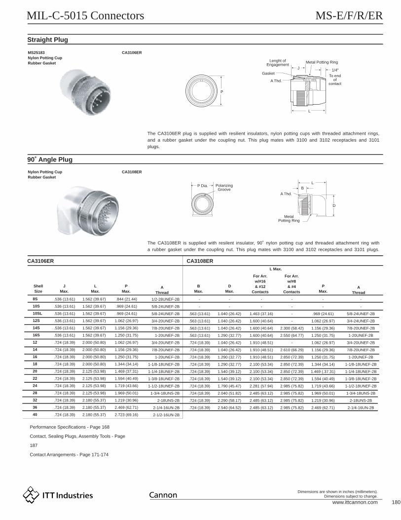
CA3106ER CA3108ER
MS25183Nylon Potting CupRubber Gasket
CA3106ER
P
P Dia. PolarizingGroove
A Thd.
BL
D
A Thd.
Gasket
Lenght ofEngagement
Metal Potting Ring
J
To endof
contact
1/4"
L
MetalPotting Ring
Nylon Potting CupRubber Gasket
CA3108ER
ShellSize
JMax.
LMax.
PMax.
BMax.
DMax.
PMax.
L Max.
For Arr.w/#16& #12
Contacts
For Arr.w/#8& #4
Contacts
Performance Specifications - Page 168
Contact, Sealing Plugs, Assembly Tools - Page
187
Contact Arrangements - Page 171-174
8S
10S
10SL
12S
14S
16S
12
14
16
18
20
22
24
28
32
36
40
AThread
1/2-28UNEF-2B
5/8-24UNEF-2B
5/8-24UNEF-2B
3/4-20UNEF-2B
7/8-20UNEF-2B
1-20UNEF-2B
3/4-20UNEF-2B
7/8-20UNEF-2B
1-20UNEF-2B
1-1/8-18UNEF-2B
1-1/4-18UNEF-2B
1-3/8-18UNEF-2B
1-1/2-18UNEF-2B
1-3/4-18UNS-2B
2-18UNS-2B
2-1/4-16UN-2B
2-1/2-16UN-2B
AThread
-
-
5/8-24UNEF-2B
3/4-24UNEF-2B
7/8-20UNEF-2B
1-20UNEF-2B
3/4-20UNEF-2B
7/8-20UNEF-2B
1-20UNEF-2B
1-1/8-18UNEF-2B
1-1/4-18UNEF-2B
1-3/8-18UNEF-2B
1-1/2-18UNEF-2B
1-3/4-18UNS-2B
2-18UNS-2B
2-1/4-16UN-2B
-
-
.563 (13.61)
.563 (13.61)
.563 (13.61)
.563 (13.61)
.724 (18.39)
.724 (18.39)
.724 (18.39)
.724 (18.39)
.724 (18.39)
.724 (18.39)
.724 (18.39)
.724 (18.39)
.724 (18.39)
.724 (18.39)
-
-
1.040 (26.42)
1.040 (26.42)
1.040 (26.42)
1.290 (32.77)
1.040 (26.42)
1.040 (26.42)
1.290 (32.77)
1.290 (32.77)
1.540 (39.12)
1.540 (39.12)
1.790 (45.47)
2.040 (51.82)
2.290 (58.17)
2.540 (64.52)
-
-
1.463 (37.16)
1.600 (40.64)
1.600 (40.64)
1.600 (40.64)
1.910 (48.51)
1.910 (48.51)
1.910 (48.51)
2.100 (53.34)
2.100 (53.34)
2.100 (53.34)
2.281 (57.94)
2.485 (63.12)
2.485 (63.12)
2.485 (63.12)
-
-
-
-
2.300 (58.42)
2.550 (64.77)
-
2.610 (66.29)
2.850 (72.39)
2.850 (72.39)
2.850 (72.39)
2.850 (72.39)
2.985 (75.82)
2.985 (75.82)
2.985 (75.82)
2.985 (75.82)
-
-
.969 (24.61)
1.062 (26.97)
1.156 (29.36)
1.250 (31.75)
1.062 (26.97)
1.156 (29.36)
1.250 (31.75)
1.344 (34.14)
1.469 (.37.31)
1.594 (40.49)
1.719 (43.66)
1.969 (50.01)
1.219 (30.96)
2.469 (62.71)
.536 (13.61)
.536 (13.61)
.536 (13.61)
.536 (13.61)
.536 (13.61)
.536 (13.61)
.724 (18.39)
.724 (18.39)
.724 (18.39)
.724 (18.39)
.724 (18.39)
.724 (18.39)
.724 (18.39)
.724 (18.39)
.724 (18.39)
.724 (18.39)
.724 (18.39)
1.562 (39.67)
1.562 (39.67)
1.562 (39.67)
1.562 (39.67)
1.562 (39.67)
1.562 (39.67)
2.000 (50.80)
2.000 (50.80)
2.000 (50.80)
2.000 (50.80)
2.125 (53.98)
2.125 (53.98)
2.125 (53.98)
2.125 (53.98)
2.180 (55.37)
2.180 (55.37)
2.180 (55.37)
.844 (21.44)
.969 (24.61)
.969 (24.61)
1.062 (26.97)
1.156 (29.36)
1.250 (31.75)
1.062 (26.97)
1.156 (29.36)
1.250 (31.75)
1.344 (34.14)
1.469 (37.31)
1.594 (40.49)
1.719 (43.66)
1.969 (50.01)
1.219 (30.96)
2.469 (62.71)
2.723 (69.16)
The CA3106ER plug is supplied with resilient insulators, nylon potting cups with threaded attachment rings,
and a rubber gasket under the coupling nut. This plug mates with 3100 and 3102 receptacles and 3101
plugs.
The CA3108ER is supplied with resilent insulator, 90˚ nylon potting cup and threaded attachment ring with
a rubber gasket under the coupling nut. This plug mates with 3100 and 3102 receptacles and 3101 plugs.
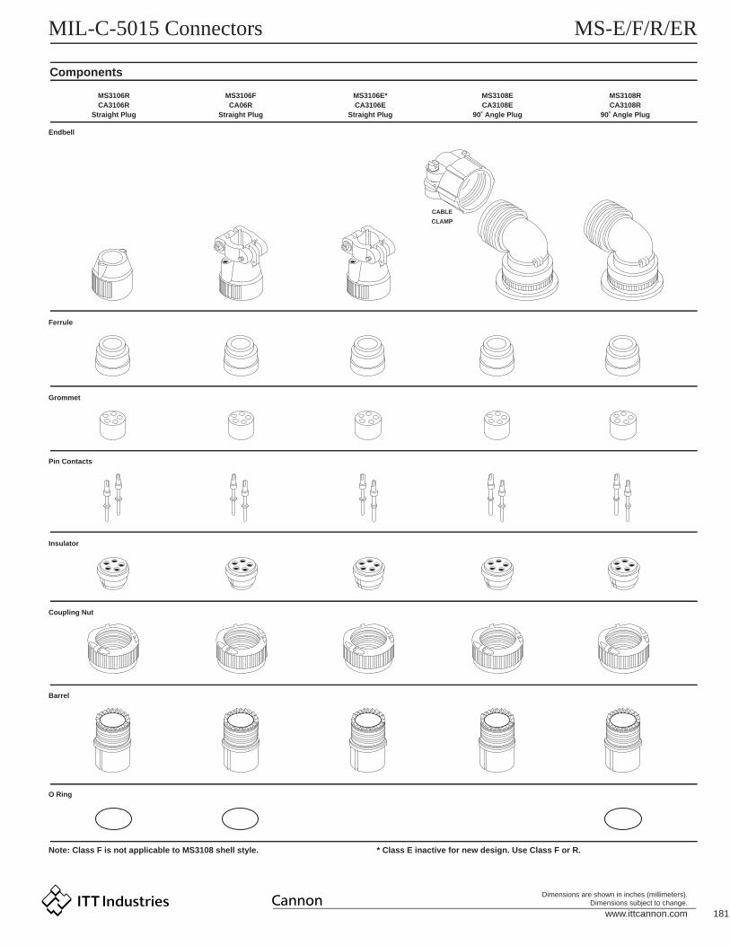
www.ittcannon.com 181
Dimensions are shown in inches (millimeters).Dimensions subject to change.
MIL-C-5015 Connectors MS-E/F/R/ER
Components
MS3106RCA3106R
Straight Plug
Endbell
Ferrule
Grommet
Pin Contacts
Insulator
Coupling Nut
Barrel
O Ring
Note: Class F is not applicable to MS3108 shell style. * Class E inactive for new design. Use Class F or R.
MS3106FCA06R
Straight Plug
MS3106E*CA3106E
Straight Plug
MS3108ECA3108E
90˚ Angle Plug
CABLE
CLAMP
MS3108RCA3108R
90˚ Angle Plug


![Index [] · This catalogue describes the standard and special purpose designs used in Military and industrial circular connectors meeting the following specifications. MIL-C-5015](https://static.fdocuments.in/doc/165x107/6038ccf7b3dc96029852a182/index-this-catalogue-describes-the-standard-and-special-purpose-designs-used.jpg)