Mike Brennan and Mike Blaskiewicz Brookhaven ... -...
21
Stochastic Cooling in RHIC Mike Brennan and Mike Blaskiewicz Brookhaven National Lab Collider-Accelerator Department Particle Accelerator Conference 2009 Vancouver, Canada May 6, 2009
Transcript of Mike Brennan and Mike Blaskiewicz Brookhaven ... -...
Stochastic Cooling in RHICMike Brennan and Mike Blaskiewicz
Brookhaven National LabCollider-Accelerator Department
Particle Accelerator Conference 2009Vancouver, Canada
May 6, 2009
May 6, 2009 BNL - RHIC 2
Acknowledgements
Mike and I want the thank Dave McGinnis and Ralph Pasquinelli of FermilabAnd Fritz Caspers of CERNFor countless gems of advice and suggestions, and for
their longstanding encouragement of this project
May 6, 2009 BNL - RHIC 3
Outline
• The overall plan for stochastic cooling at RHIC• Motivation, to counteract IBS; Context, why we are
implementing S.C. now, and not before• Technical aspects, challenges of bunched beam,
narrowband kickers, signal processing• Results with beam, longitudinal cooling• Simulations and luminosity projections
May 6, 2009 BNL - RHIC 4
Overall Plan for Stochastic Cooling in RHIC
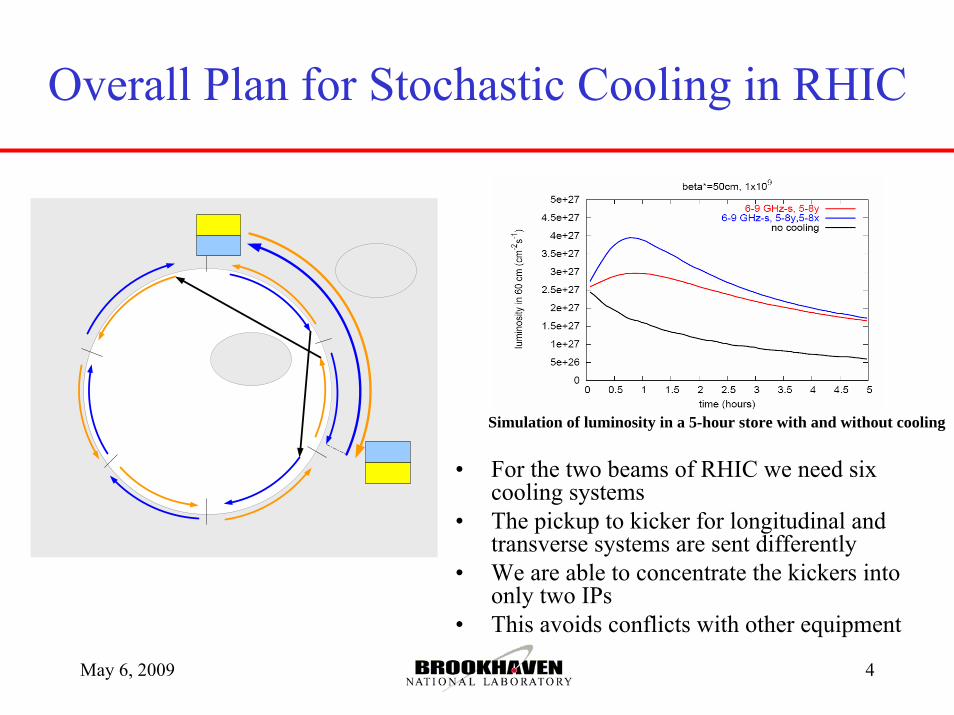
• For the two beams of RHIC we need six cooling systems
• The pickup to kicker for longitudinal and transverse systems are sent differently
• We are able to concentrate the kickers into only two IPs
• This avoids conflicts with other equipment
Simulation of luminosity in a 5-hour store with and without cooling
May 6, 2009 BNL - RHIC 5
The purpose of Stochastic Cooling is to Counteract Intra-Beam Scattering
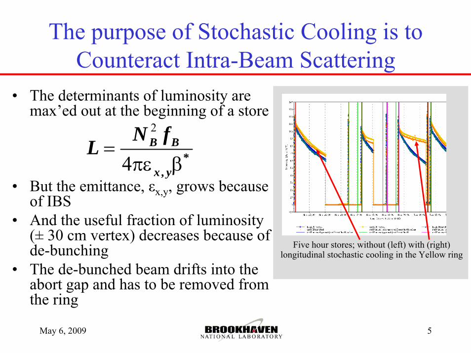
• The determinants of luminosity are max’ed out at the beginning of a store
• But the emittance, εx,y, grows because of IBS
• And the useful fraction of luminosity (± 30 cm vertex) decreases because of de-bunching
• The de-bunched beam drifts into the abort gap and has to be removed from the ring
2
4 *,
=πε β
B B
x y
N fL
Five hour stores; without (left) with (right) longitudinal stochastic cooling in the Yellow ring
May 6, 2009 BNL - RHIC 6
To Beat IBS the Cooling Time Must be Less Than 1 Hour
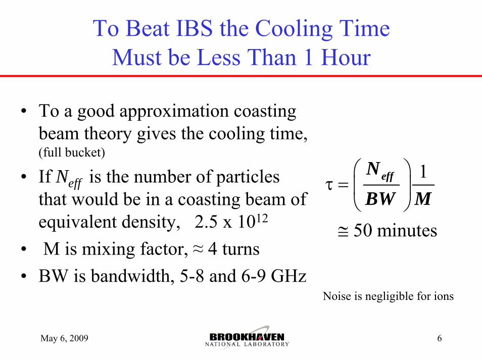
• To a good approximation coasting beam theory gives the cooling time, (full bucket)
• If Neff is the number of particles that would be in a coasting beam of equivalent density, 2.5 x 10¹²
• M is mixing factor, ≈ 4 turns• BW is bandwidth, 5-8 and 6-9 GHz
1
50 minutes
⎛ ⎞τ = ⎜ ⎟
⎝ ⎠≅
effNBW M
Noise is negligible for ions
May 6, 2009 BNL - RHIC 7
So why are we doing stochastic cooling now and not years before?
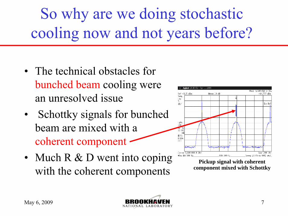
• The technical obstacles for bunched beam cooling were an unresolved issue
• Schottky signals for bunched beam are mixed with a coherent component
• Much R & D went into coping with the coherent components
Pickup signal with coherent component mixed with Schottky
May 6, 2009 BNL - RHIC 8
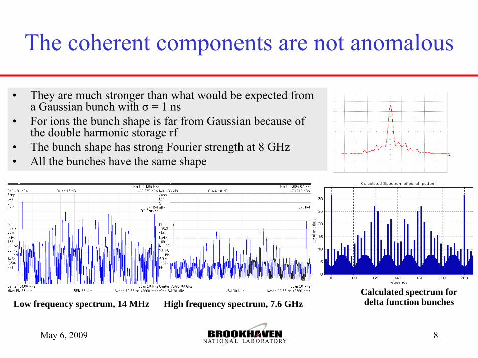
• They are much stronger than what would be expected from a Gaussian bunch with σ = 1 ns
• For ions the bunch shape is far from Gaussian because of the double harmonic storage rf
• The bunch shape has strong Fourier strength at 8 GHz• All the bunches have the same shape
The coherent components are not anomalous
Low frequency spectrum, 14 MHz High frequency spectrum, 7.6 GHzCalculated spectrum for delta function bunches
May 6, 2009 BNL - RHIC 9
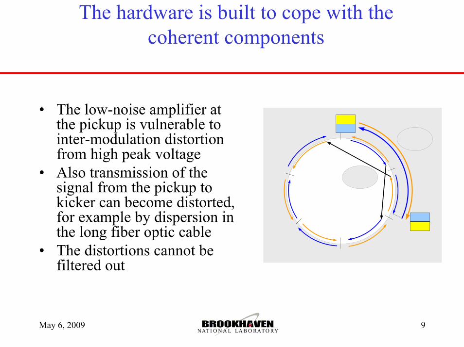
The hardware is built to cope with the coherent components
• The low-noise amplifier at the pickup is vulnerable to inter-modulation distortion from high peak voltage
• Also transmission of the signal from the pickup to kicker can become distorted, for example by dispersion in the long fiber optic cable
• The distortions cannot be filtered out
May 6, 2009 BNL - RHIC 10
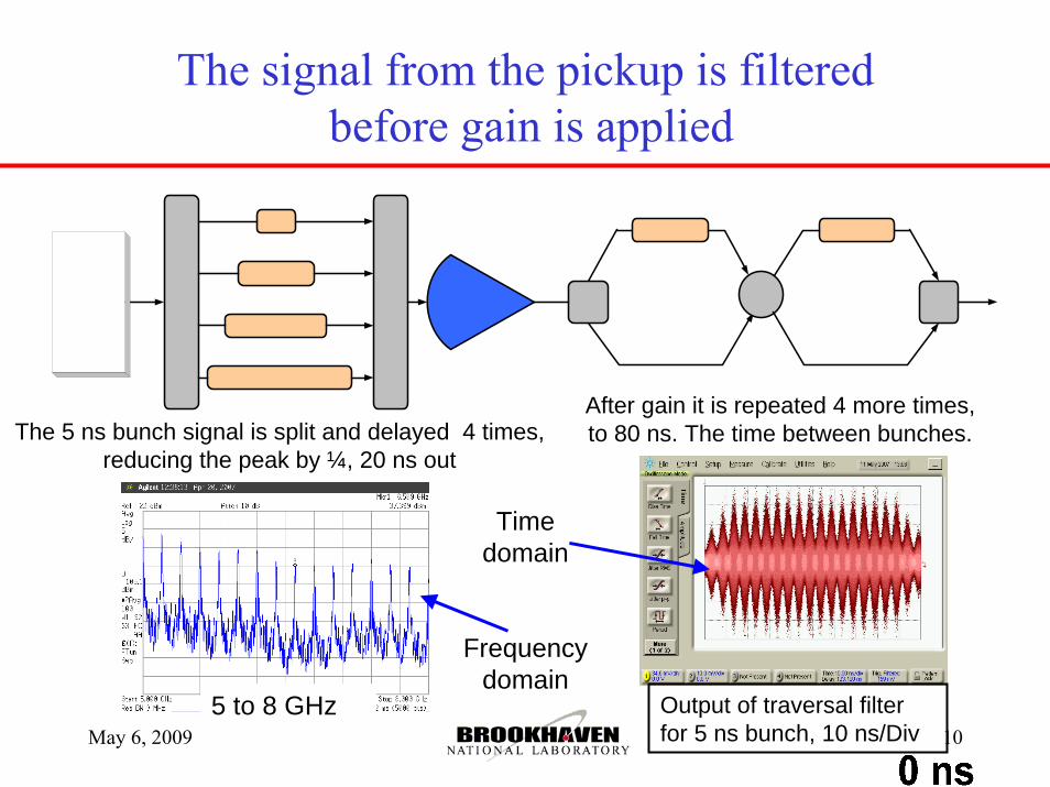
The signal from the pickup is filteredbefore gain is applied
The 5 ns bunch signal is split and delayed 4 times, reducing the peak by ¼, 20 ns out
After gain it is repeated 4 more times, to 80 ns. The time between bunches.
Time domain
Frequency domain
Output of traversal filter for 5 ns bunch, 10 ns/Div
5 to 8 GHz
May 6, 2009 BNL - RHIC 11
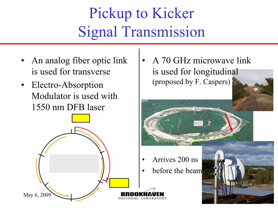
Pickup to Kicker Signal Transmission
• An analog fiber optic link is used for transverse
• Electro-Absorption Modulator is used with 1550 nm DFB laser
• A 70 GHz microwave link is used for longitudinal (proposed by F. Caspers)
• Arrives 200 ns • before the beam
May 6, 2009 BNL - RHIC 12
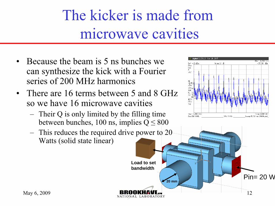
Pin= 20 W
Load to set bandwidth
20 mm
• Because the beam is 5 ns bunches we can synthesize the kick with a Fourier series of 200 MHz harmonics
• There are 16 terms between 5 and 8 GHz so we have 16 microwave cavities– Their Q is only limited by the filling time
between bunches, 100 ns, implies Q ≤ 800– This reduces the required drive power to 20
Watts (solid state linear)
The kicker is made frommicrowave cavities
May 6, 2009 BNL - RHIC 13
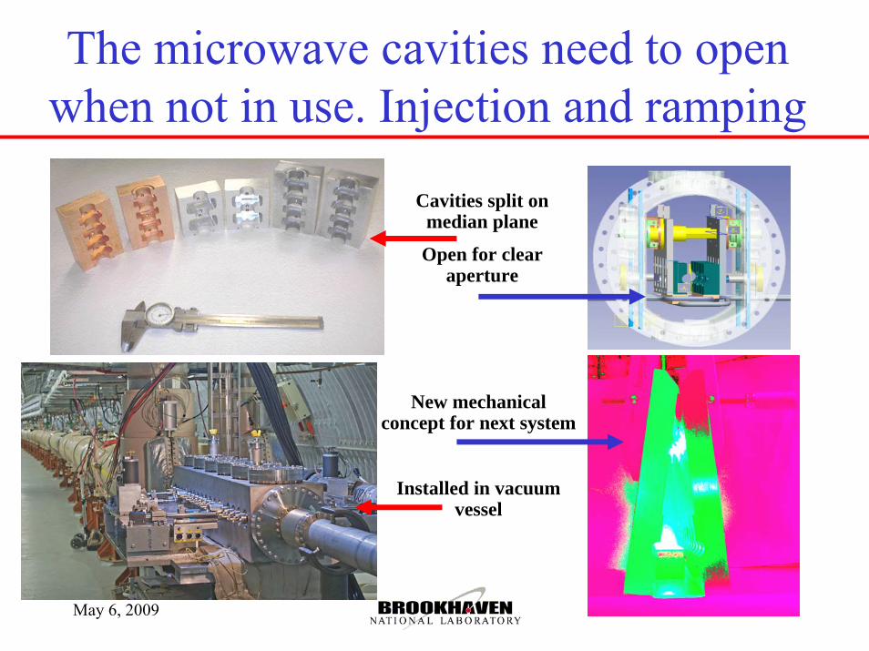
The microwave cavities need to open when not in use. Injection and ramping
Cavities split on median plane
Open for clear aperture
New mechanical concept for next system
Installed in vacuum vessel
May 6, 2009 BNL - RHIC 14
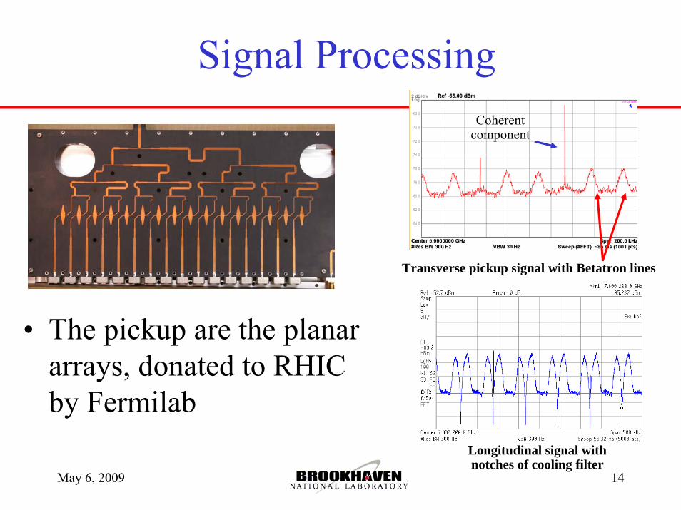
Signal Processing
• The pickup are the planar arrays, donated to RHIC by Fermilab
Transverse pickup signal with Betatron lines
Coherent component
Longitudinal signal with notches of cooling filter
May 6, 2009 BNL - RHIC 15
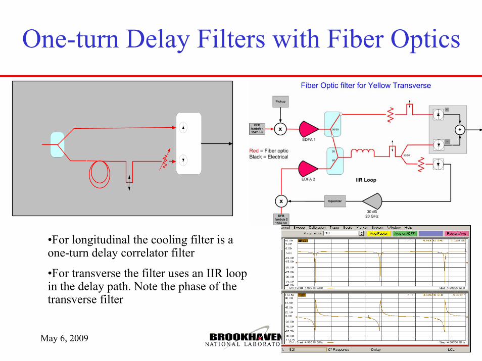
One-turn Delay Filters with Fiber Optics
•For longitudinal the cooling filter is a one-turn delay correlator filter
•For transverse the filter uses an IIR loop in the delay path. Note the phase of the transverse filter
May 6, 2009 BNL - RHIC 16
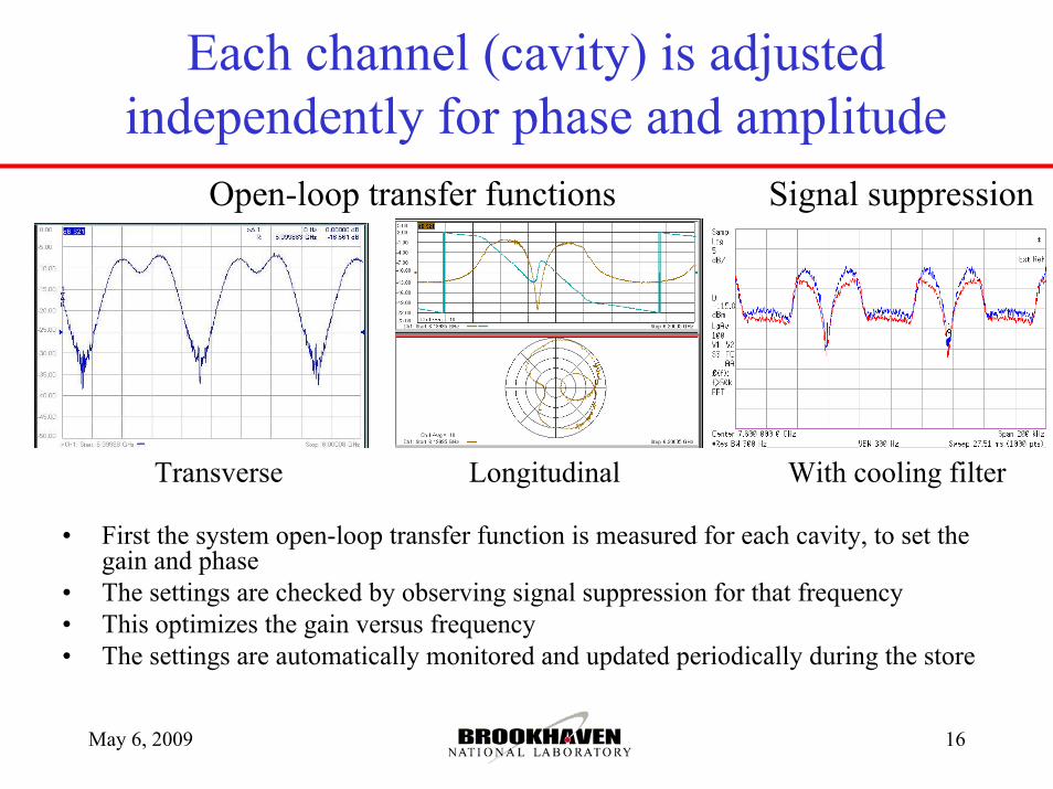
Each channel (cavity) is adjusted independently for phase and amplitude
• First the system open-loop transfer function is measured for each cavity, to set the gain and phase
• The settings are checked by observing signal suppression for that frequency• This optimizes the gain versus frequency• The settings are automatically monitored and updated periodically during the store
Signal suppression Open-loop transfer functions
Transverse Longitudinal With cooling filter
May 6, 2009 BNL - RHIC 17
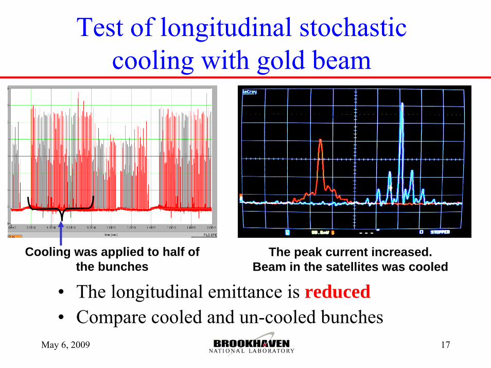
Test of longitudinal stochastic cooling with gold beam
• The longitudinal emittance is reduced• Compare cooled and un-cooled bunches
Cooling was applied to half of the bunches
The peak current increased. Beam in the satellites was cooled
May 6, 2009 BNL - RHIC 18
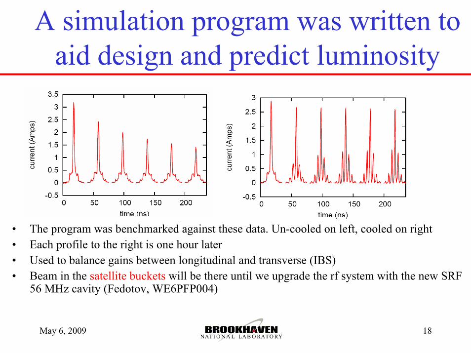
A simulation program was written to aid design and predict luminosity
• The program was benchmarked against these data. Un-cooled on left, cooled on right• Each profile to the right is one hour later• Used to balance gains between longitudinal and transverse (IBS)• Beam in the satellite buckets will be there until we upgrade the rf system with the new SRF
56 MHz cavity (Fedotov, WE6PFP004)

May 6, 2009 BNL - RHIC 19
Projected Luminosity Improvement with Transverse and Longitudinal Cooling
Simulations of luminosity for a 5 hour store with; red=no cooling, green=cooling, blue=56 MHz SRF harmonic cavity
• Transverse and longitudinal interact via IBS
• Shortening the bunch increases transverse IBS
• X 4 increase in integrated luminosity is expected
May 6, 2009 BNL - RHIC 20
Status and Plans
• Now we have three of the six phase space planes ready– Longitudinal, Yellow(1) and Blue(2) (with microwave link)– Transverse, Vertical(3) in Yellow ring
• Shutdown of 2009 we add Vertical in Blue(4), the microwave link in Yellow longitudinal
• Shutdown of 2010 we add Horizontal(5+6) to complete• Only Yellow longitudinal has seen ions so far• In the future (?) we would like to upgrade the
longitudinal to 12 GHz
May 6, 2009 BNL - RHIC 21
Summary
• Cooling of bunched beam ions in RHIC has been accomplished
• It has been used operationally for two runs with gold ions in one ring
• We are about half way complete on a full six plane system
• We expect stochastic cooling to increase the integrated luminosity of gold collisions by approximately a factor of 4 over no cooling