MIDI Standard for Dummies Implementing MIDI Outdelliott/ece492/appnotes/2015w/G7_MIDI... · MIDI...
8
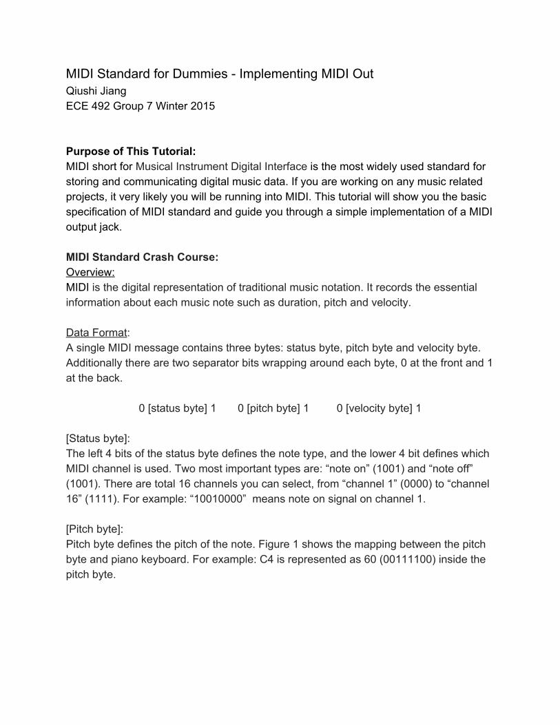
MIDI Standard for Dummies Implementing MIDI Out Qiushi Jiang ECE 492 Group 7 Winter 2015 Purpose of This Tutorial: MIDI short for Musical Instrument Digital Interface is the most widely used standard for storing and communicating digital music data. If you are working on any music related projects, it very likely you will be running into MIDI. This tutorial will show you the basic specification of MIDI standard and guide you through a simple implementation of a MIDI output jack. MIDI Standard Crash Course: Overview: MIDI is the digital representation of traditional music notation. It records the essential information about each music note such as duration, pitch and velocity. Data Format : A single MIDI message contains three bytes: status byte, pitch byte and velocity byte. Additionally there are two separator bits wrapping around each byte, 0 at the front and 1 at the back. 0 [status byte] 1 0 [pitch byte] 1 0 [velocity byte] 1 [Status byte]: The left 4 bits of the status byte defines the note type, and the lower 4 bit defines which MIDI channel is used. Two most important types are: “note on” (1001) and “note off” (1001). There are total 16 channels you can select, from “channel 1” (0000) to “channel 16” (1111). For example: “10010000” means note on signal on channel 1. [Pitch byte]: Pitch byte defines the pitch of the note. Figure 1 shows the mapping between the pitch byte and piano keyboard. For example: C4 is represented as 60 (00111100) inside the pitch byte.
Transcript of MIDI Standard for Dummies Implementing MIDI Outdelliott/ece492/appnotes/2015w/G7_MIDI... · MIDI...
MIDI Standard for Dummies Implementing MIDI Out Qiushi Jiang ECE 492 Group 7 Winter 2015 Purpose of This Tutorial: MIDI short for Musical Instrument Digital Interface is the most widely used standard for storing and communicating digital music data. If you are working on any music related projects, it very likely you will be running into MIDI. This tutorial will show you the basic specification of MIDI standard and guide you through a simple implementation of a MIDI output jack. MIDI Standard Crash Course: Overview: MIDI is the digital representation of traditional music notation. It records the essential information about each music note such as duration, pitch and velocity. Data Format: A single MIDI message contains three bytes: status byte, pitch byte and velocity byte. Additionally there are two separator bits wrapping around each byte, 0 at the front and 1 at the back.
0 [status byte] 1 0 [pitch byte] 1 0 [velocity byte] 1
[Status byte]: The left 4 bits of the status byte defines the note type, and the lower 4 bit defines which MIDI channel is used. Two most important types are: “note on” (1001) and “note off” (1001). There are total 16 channels you can select, from “channel 1” (0000) to “channel 16” (1111). For example: “10010000” means note on signal on channel 1. [Pitch byte]: Pitch byte defines the pitch of the note. Figure 1 shows the mapping between the pitch byte and piano keyboard. For example: C4 is represented as 60 (00111100) inside the pitch byte.
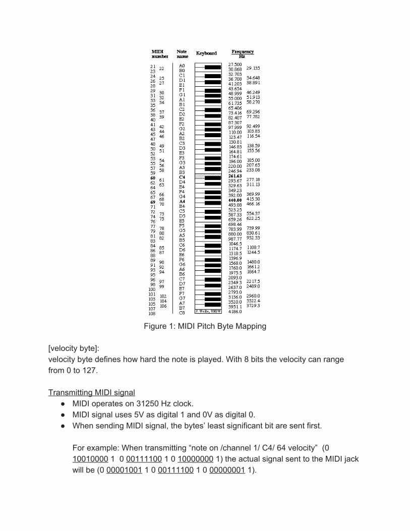
Figure 1: MIDI Pitch Byte Mapping
[velocity byte]: velocity byte defines how hard the note is played. With 8 bits the velocity can range from 0 to 127. Transmitting MIDI signal
MIDI operates on 31250 Hz clock. MIDI signal uses 5V as digital 1 and 0V as digital 0. When sending MIDI signal, the bytes’ least significant bit are sent first.
For example: When transmitting “note on /channel 1/ C4/ 64 velocity” (0 10010000 1 0 00111100 1 0 10000000 1) the actual signal sent to the MIDI jack will be (0 00001001 1 0 00111100 1 0 00000001 1).
MIDI out is fixed at 5V when there is no signal.
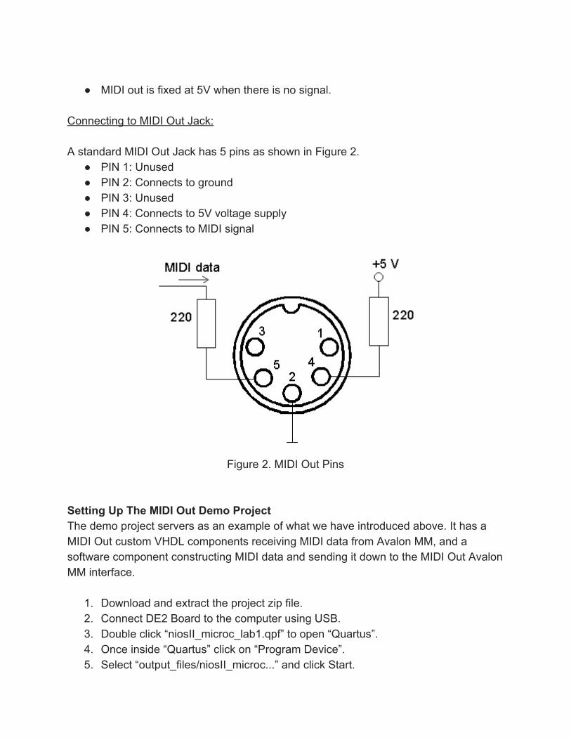
Connecting to MIDI Out Jack: A standard MIDI Out Jack has 5 pins as shown in Figure 2.
PIN 1: Unused PIN 2: Connects to ground PIN 3: Unused PIN 4: Connects to 5V voltage supply PIN 5: Connects to MIDI signal
Figure 2. MIDI Out Pins
Setting Up The MIDI Out Demo Project The demo project servers as an example of what we have introduced above. It has a MIDI Out custom VHDL components receiving MIDI data from Avalon MM, and a software component constructing MIDI data and sending it down to the MIDI Out Avalon MM interface.
1. Download and extract the project zip file. 2. Connect DE2 Board to the computer using USB. 3. Double click “niosII_microc_lab1.qpf” to open “Quartus”. 4. Once inside “Quartus” click on “Program Device”. 5. Select “output_files/niosII_microc...” and click Start.
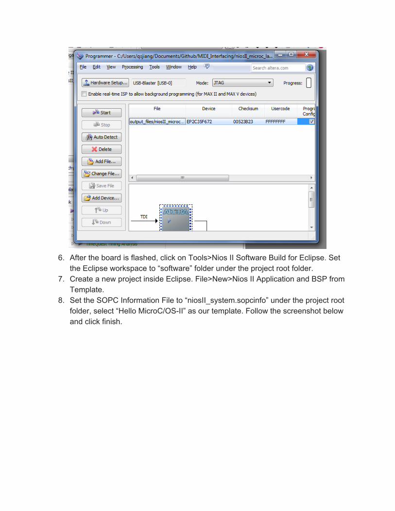
6. After the board is flashed, click on Tools>Nios II Software Build for Eclipse. Set
the Eclipse workspace to “software” folder under the project root folder. 7. Create a new project inside Eclipse. File>New>Nios II Application and BSP from
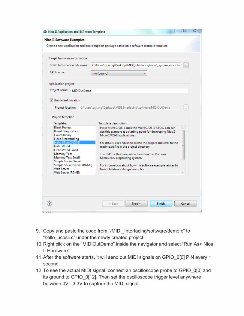
Template. 8. Set the SOPC Information File to “niosII_system.sopcinfo” under the project root
folder, select “Hello MicroC/OSII” as our template. Follow the screenshot below and click finish.
9. Copy and paste the code from “/MIDI_Interfacing/software/demo.c” to “hello_ucosii.c” under the newly created project.
10.Right click on the “MIDIOutDemo” inside the navigator and select “Run As> Nios II Hardware”.
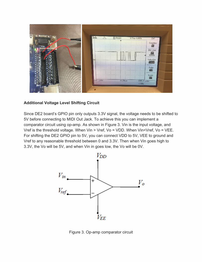
11.After the software starts, it will send out MIDI signals on GPIO_0[0] PIN every 1 second.
12.To see the actual MIDI signal, connect an oscilloscope probe to GPIO_0[0] and its ground to GPIO_0[12]. Then set the oscilloscope trigger level anywhere between 0V 3.3V to capture the MIDI signal.
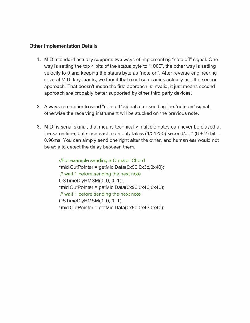
Additional Voltage Level Shifting Circuit Since DE2 board’s GPIO pin only outputs 3.3V signal, the voltage needs to be shifted to 5V before connecting to MIDI Out Jack. To achieve this you can implement a comparator circuit using opamp. As shown in Figure 3. Vin is the input voltage, and Vref is the threshold voltage. When Vin > Vref, Vo = VDD. When Vin<Vref, Vo = VEE. For shifting the DE2 GPIO pin to 5V, you can connect VDD to 5V, VEE to ground and Vref to any reasonable threshold between 0 and 3.3V. Then when Vin goes high to 3.3V, the Vo will be 5V, and when Vin in goes low, the Vo will be 0V.
Figure 3. Opamp comparator circuit
Other Implementation Details
1. MIDI standard actually supports two ways of implementing “note off” signal. One way is setting the top 4 bits of the status byte to “1000”, the other way is setting velocity to 0 and keeping the status byte as “note on”. After reverse engineering several MIDI keyboards, we found that most companies actually use the second approach. That doesn’t mean the first approach is invalid, it just means second approach are probably better supported by other third party devices.
2. Always remember to send “note off” signal after sending the “note on” signal,
otherwise the receiving instrument will be stucked on the previous note.
3. MIDI is serial signal, that means technically multiple notes can never be played at the same time, but since each note only takes (1/31250) second/bit * (8 + 2) bit = 0.96ms. You can simply send one right after the other, and human ear would not be able to detect the delay between them.
//For example sending a C major Chord *midiOutPointer = getMidiData(0x90,0x3c,0x40); // wait 1 before sending the next note OSTimeDlyHMSM(0, 0, 0, 1);. *midiOutPointer = getMidiData(0x90,0x40,0x40); // wait 1 before sending the next note OSTimeDlyHMSM(0, 0, 0, 1); *midiOutPointer = getMidiData(0x90,0x43,0x40);
Reference: MIDI 1.0 Detailed Specification http://oktopus.hu/uploaded/Tudastar/MIDI%201.0%20Detailed%20Specification.pdf Accessed on: April 7, 2015. Figure 1: MIDI Pitch Byte Mapping retrived from http://newt.phys.unsw.edu.au/jw/notes.html Accessed on: April 7, 2015. Figure 2. MIDI Out Pins retrived from http://tryndelka.narod.ru/ Accessed on: April 7, 2015.
Figure 3. Opamp comparator circuit retrieved from http://ocw.mit.edu/courses/electricalengineeringandcomputerscience/ Accessed on: April 7, 2015.