Middle East District Design Instructions Manual · INTRODUCTION . The MIDDLE EAST DISTRICT DESIGN...
417
Middle East District Design Instructions Manual April 2014
-
Upload
hoangkhuong -
Category
Documents
-
view
228 -
download
0
Transcript of Middle East District Design Instructions Manual · INTRODUCTION . The MIDDLE EAST DISTRICT DESIGN...
Middle East District
Design Instructions
Manual
April 2014

Middle East District April 2014 Design Instructions Manual
Revisions
June 2013 – Reformatting for QMS
February 2014 – Add Authorized Scope of Work for MILCON Project to Chapter. Correct Website on Introduction.
April 2014 – Replace Chapter 2 Presentation of Data
ii

Middle East District April 2014 Design Instructions Manual
INTRODUCTION
The MIDDLE EAST DISTRICT DESIGN INSTRUCTIONS MANUAL consists of the following:
1 DESIGN INSTRUCTIONS
2 Supplement: DESIGN CHECKLIST
Revisions will be issued to this manual as necessary. Specific comments on the contents are requested from the users and should be directed to Engineering Management Support Branch (CETAM-EN-M), Attn: Mr. John Adams, e-mail address “[email protected]” (540) 665-3661.
DESIGN INSTRUCTIONS MANUAL presents standard procedures and guidance for the preparation of designs by both Architect Engineer (A-E) firms and U.S. Army Corps of Engineers (USACE) personnel. It presents general instructions as well as detailed requirements for the various design disciplines. All personnel performing design for the Middle East District should thoroughly familiarize themselves with the guidance contained herein.
An electronic copy of this document and all design checklist are posted on the MED Engineering Public Webpage for access by groups outside MED and USACE. The MED Engineering Public Webpage is: http://www.tam.usace.army.mil/BusinessWithUs/Engineering/EngineeringFiles.aspx
DISCLAIMER: It is the intent of the Corps of Engineers (CE) to provide quality construction based on U.S. construction standards. By regulation, the Middle East District (MED) has been mandated to use the metric system as the national system of measure. In some instances, English units of measure are still used within this manual. This use of English measurements shall not be construed as, nor constitute a waiver to the requirements to use metric units of measure. It is the sole responsibility of the designers or Architect-Engineer to verify and ensure conversion of all English units of measure to the appropriate metric unit of measure in accordance with Corps of Engineers Guide Specification 01415 entitled METRIC MEASUREMENTS.
iii
Middle East District April 2014 Design Instructions Manual
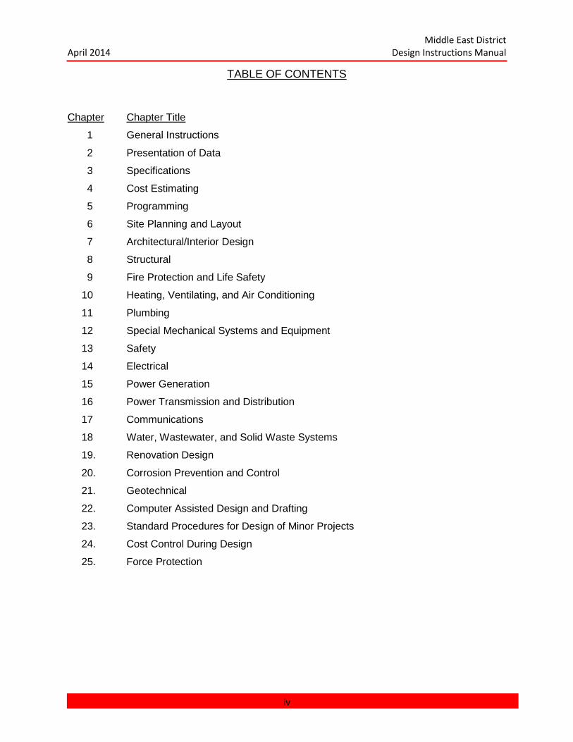
TABLE OF CONTENTS
Chapter Chapter Title
1 General Instructions
2 Presentation of Data
3 Specifications
4 Cost Estimating
5 Programming
6 Site Planning and Layout
7 Architectural/Interior Design
8 Structural
9 Fire Protection and Life Safety
10 Heating, Ventilating, and Air Conditioning
11 Plumbing
12 Special Mechanical Systems and Equipment
13 Safety
14 Electrical
15 Power Generation
16 Power Transmission and Distribution
17 Communications
18 Water, Wastewater, and Solid Waste Systems
19. Renovation Design
20. Corrosion Prevention and Control
21. Geotechnical
22. Computer Assisted Design and Drafting
23. Standard Procedures for Design of Minor Projects
24. Cost Control During Design
25. Force Protection
iv

Middle East District April 2014 Design Instructions Manual
CHAPTER COORDINATION RESPONSIBILITIES
CHAPTER CHAPTER TITLE SECTION 1 General Instructions CETAM-EN-M
2 Presentation of Data CETAM-EN-M
3 Specifications CETAM-EN-T
4 Cost Estimating CETAM-EN-T
5 Programming All Sections
6 Site Planning CETAM-EN-C
7 Architecture and Interior Design CETAM-EN-A
8 Structural CETAM-EN-A
9 Fire Protection and Life Safety CETAM-EN-B
10 Heating Ventilation and Air Conditioning CETAM-EN-B
11 Plumbing CETAM-EN-B
12 Special Mechanical Systems and Equipment CETAN-EN-B
13 Safety All Sections
14 Electrical CETAM-EN-E
15 Power Generation CETAM-EN-E
16 Power Transmission and Distribution CETAM-CE-E
17 Communications CETAM-EN-E
18 Water, Waste water and Solid Waste Systems CETAM-EN-C
19 Renovation Design CETAM-EN-A
20 Corrosion Prevention and Control CETAM EN-C
21 Geotechnical CETAM-EM-C
22 Computer Assisted Design and Drafting CETAM-EN-M
23 Standard Procedures for Design of MinorProjects All Sections
24 Cost Control During Design CETAM-EN-T
25 Force Protection All Sections
v

Middle East District April 2014 Design Instructions Manual
CHAPTER 1 GENERAL INSTRUCTIONS
CHAPTER 1 GENERAL INSTRUCTIONS ........................................................................... 1-1
1.1 GENERAL ...................................................................................................................... 1-3
1.2 APPLICABLE PUBLICATIONS. ..................................................................................... 1-3
1.3 INSTRUCTIONS ............................................................................................................ 1-3
1.3.1 Assignment of Project Manager ............................................................................. 1-3
1.3.2 Conduct of Work .................................................................................................... 1-4
1.3.3 Quality of Work ...................................................................................................... 1-4
1.3.4 Design Priorities ..................................................................................................... 1-4
1.3.5 Design Specialists ................................................................................................. 1-5
1.3.6 Value Engineering ................................................................................................. 1-5
1.3.7 Architectural Studies .............................................................................................. 1-5
1.3.8 Engineering Studies ............................................................................................... 1-6
1.3.9 Project Specific Criteria .......................................................................................... 1-6
1.3.10 Technical Criteria ................................................................................................. 1-7
1.3.11 Design Phases ..................................................................................................... 1-7
1.3.12 Design Reviews ................................................................................................... 1-7
1.3.13 Occupational Safety and Health Act ..................................................................... 1-7
1.3.14 Asbestos Containing Materials ............................................................................. 1-8
1.3.15 LEED Requirements ............................................................................................ 1-8
1.3.16 Applicable Codes ................................................................................................. 1-8
1.3.17 Authorized Scope of Work for MILCON Projects .................................................. 1-9
1.4 DEFINITIONS .............................................................................................................. 1-10
1.4.1 Basis of Design ................................................................................................... 1-10
1.4.2 Cost Estimates .................................................................................................... 1-10
1.4.3 Design Analysis ................................................................................................... 1-10
1.4.4 Drawings ............................................................................................................. 1-10
1.4.5 Life-Cycle Cost (LCC) Analysis ............................................................................ 1-11
1.4.6 Classification of Equipment and Furnishings ....................................................... 1-11
1.4.7 Construction Plan-Network Analysis System (CP-NAS) ....................................... 1-12
1.4.8 Specifications ...................................................................................................... 1-13
1-1

Middle East District April 2014 Design Instructions Manual
1.4.9 Transfer and Acceptance of Military Real Property .............................................. 1-13
1.5 SUBMITTAL REQUIREMENTS.................................................................................... 1-13
1.5.1 Programming Phase Submittal ............................................................................ 1-13
1.5.2 Concept Phase Submittal .................................................................................... 1-14
1.5.3 Preliminary Review Submittal .............................................................................. 1-14
1.5.4 Final Review Submittal ........................................................................................ 1-14
1.5.5 RTA Submittal ..................................................................................................... 1-14
1.5.6 Award Set Document ........................................................................................... 1-15
1.5.7 Summary Chart ................................................................................................... 1-15
1.5.8 CADD Files .......................................................................................................... 1-15
1.5.9 FIGURE 1 ............................................................................................................ 1-16
1-2

Middle East District April 2014 Design Instructions Manual
CHAPTER 1 GENERAL INSTRUCTIONS
1.1 GENERAL
This manual prescribes general procedures and instructions required to program, design, and prepare specifications, drawings, design analyses, and cost estimates for projects under the responsibility of the U.S. Army Corps of Engineers (USACE), Middle East District. This manual shall be used under the direction of U.S. Army Corps of Engineers, Middle East District (CETAM) and will be a part of all Architect Engineer (A-E) contracts. Should this manual and the contract documents conflict, the contract will take precedence. Any conflicts between referenced documents in the contract documents and this manual excluding codes, this manual will take precedence. The A-E shall document each conflict in writing and bring it to the immediate attention of the CETAM Project Manager.
1.2 APPLICABLE PUBLICATIONS.
The current edition of the publications listed below, form a part of this manual.
ER 1-1-11. Network Analysis System.
ER 415-1-10. Construction, Contractor Submittal Procedures
ER 415-345-38 Transfer and Acceptance of Military Real Property.
ER 1110-345-720. Engineering & Design Construction Specifications
TI-800-01 Technical Instructions Design Criteria
ETL 1110-3-332 Engineering and Design; Economic Studies, 22 March 1987.
TM 5-802-1. Economic Studies for Military Construction-Applications.
Department of the Army, Publication.
Engineering Economic Studies, Life Cycle Costing Instructions OCE
OSHA-CFR,Title 29, Occupational Safety and Health Act. Chapter XVII, Parts 1910 & 1926.
1.3 INSTRUCTIONS.
1.3.1 Assignment of Project Manager. Prior to A-E selection or initiation of design, a CETAM Project Manager will be designated within the Engineering & Construction Programs & Project Management Directorate (CETAM-PM). The Project Manager will be responsible for the day-to-day coordination and management of the project design and of the A-E contract. All questions shall be directed to the Project Manager. All written communications shall be
1-3

Middle East District April 2014 Design Instructions Manual
addressed to the attention of the Project Manager unless specifically directed to do otherwise, in which case, the Project Manager shall be furnished a copy. Telephone inquiries of a technical nature may be directed to the appropriate Engineering & Construction Technical Directorate (CETAM-EN) Division Chief, or a designated engineer or architect within CETAM-EN.
1.3.2 Conduct of Work. In the performance of contracts with CETAM, the A-E shall:
a. Perform the work diligently and aggressively, and promptly advise CETAM in writing of all significant developments.
b. Prepare a summary, and promptly furnish a copy thereof to CETAM, of significant telephone conversations relating to the technical phases of work under the contract.
c. Take appropriate measures to obtain clarification of design criteria requirements, to acquire all pertinent design information, and to incorporate such information in the work being performed.
d. Cooperate fully with other firms, consultants and contractors performing work under the program to which this contract pertains, upon being advised by CETAM that such firms or individuals have a legitimate interest in the program, have need-to-know status, and proper security clearance where required.
1.3.3 Quality of Work. Top quality design work is necessary for all projects under the supervision of CETAM. Contract drawings and specifications must be sufficient to attract intelligent and competitive bids and to afford a clear understanding of the construction work required. Work must be organized in a manner that will assure thorough coordination between various details on drawings, between the various sections of the specifications, and between the drawings and specifications. The A-E is expected to cross-check all work until he is professionally satisfied that no conflicts exist.
1.3.4 Design Priorities. In general, CETAM projects require consideration of harsh environment and remoteness from sources of technical supply, the high cost of construction, the low level of maintenance, and the difficulty of obtaining replacement parts, which necessitates the following design priorities:
a. Construction must have a long expected life.
b. Low maintenance materials and systems must be employed.
c. Mechanical and electrical systems must be simple to operate and easy to maintain.
d. Use of standardized materials, equipment, and systems is necessary to minimize the requirements for replacement parts, storage facilities, and service requirements.
1-4
Middle East District April 2014 Design Instructions Manual
e. Use of construction materials or techniques which are suitable for overseas work.
f. Economical construction details.
g. Realistic tolerances.
d. Unrestrictive specifications.
i. Complete design.
j. Explosives safety and fire protection requirements.
1.3.5 Design Specialists. Whenever a design specialist is required for a particular project, the A-E shall submit for the approval of the CETAM Contracting Officer, the name of the designated specialist along with the individual's educational background, experience, and licenses or registrations held, before design work commences. The design specialists shall be registered architects, registered professional engineers, or recognized consultants with a background of at least five years design experience, unless otherwise specified, in the appropriate specialty. Services of design specialists may be required in the following specialties:
Stage/Theater Design Landscape Design Food Service Design Irrigation Design (Horticultural) Medical Design Fire Protection Acoustical Design Interior Design Educational Design Security Telecommunications Audio Visual, PA, TV, etc. Geotechnical Design Hardened Structures/Force Protection Asbestos Abatement X-Ray Shielding EMF Shielding
Other problems and features which deserve the attention of specialists will be designated for specific projects.
1.3.6 Value Engineering. CETAM reserves the right to perform value engineering (V-E) studies on projects controlled by the USACE either during or after completion of design. The value engineering studies may be performed by CETAM or another A-E designated by CETAM. CETAM, at its discretion, may modify A-E contracts to implement any or all design changes resulting from the value engineering studies or the engineering evaluations after completion of design. The A-E during the course of his design shall be alert for and shall identify those high-cost low-value items or areas which he considers may be accomplished in different ways and possibly at less cost. Potential value engineering study items shall be reported to the Project Manager.
1.3.7 Architectural Studies. The models, perspectives, and color renderings, both interior and exterior, necessary for a visual presentation to the user shall be determined on a project-by-project basis and shall be furnished only as specified in the contract.
1-5

Middle East District April 2014 Design Instructions Manual
1.3.8 Engineering Studies. In addition to project design requirements discussed heretofore, CETAM may require the performance of special studies and the preparation of special estimates. The scope and requirements for these activities will be included in the contract, if required. In general, fuel selections, pollution abatement methods, and other variable processes shall be based upon life-cycle costs in accordance with AEI Design Criteria, ETL 1110-3-332 and TM 5-802-1.
1.3.9 Project Specific Criteria. CETAM will furnish the A-E with all available data and criteria concerning the work. Usually these criteria take the form of a Design Directive or a set of approved Basis of Design Documents as determined by the A-E Scope of Work. Both the Design Directive and the Basis of Design Documents are further described in Chapter 5: PROGRAMMING.
1.3.9.1 Design Directive. CETAM shall inform the A-E of the "quality, cost, and area" design parameters within which he is expected to design each facility of a project. The quality and costs for systems and finishes of a prestigious building (e.g., Headquarters building) will be higher than they would be for a utilitarian type building (i.e., warehouse). As an example, the structural system selected for a headquarters building may not be the most economical, whereas the structural system selected for the warehouse would be expected to be the most economical possible. As a further example, the mechanical system selected for a headquarters building may be relatively sophisticated to fulfill the minimum necessary requirements of the user, whereas the warehouse's mechanical system would be relatively unsophisticated.
1.3.9.2 Topographic Surveys, Easements, and Utilities. Unless otherwise stated in the contract, CETAM will be responsible for detailed topographic mapping, available easements, and utility information for the project.
1.3.9.3 Geotechnical Investigation. When required, geotechnical investigation, including subsurface explorations, sampling, field and laboratory testing, and water studies will be conducted by MED or the A-E. The results of geotechnical investigation will be contained in a geotechnical investigation report written by MED or the A-E, whichever applicable. Foundations and pavements and other Geotechnical related designs will be in accordance with the provisions of Chapter 8: STRUCTURAL, and Chapter 21: GEOTECHNICAL.
1.3.9.4 Cathodic Protection and Earth Resistance. Unless otherwise stated in the contract, the A-E will be responsible for determining whether cathodic protection on buried structures and underground utility systems are needed for special electrical grounding and counterpoise systems, and for gathering the field data necessary for design.
1.3.9.5 Water Supply and Quality Data. When specifically stated in the contract, CETAM will provide the A-E with water supply and water quality data. This data will include information on the locations and depths of all viable water supply sources at the sites involved and a water quantity and water quality analysis for each source. Water supply and treatment systems will be designed in accordance with the provisions of Chapter 18: WATER, WASTEWATER, AND SOLID WASTE SYSTEMS.
1-6
Middle East District April 2014 Design Instructions Manual
1.3.10 Technical Criteria. All designs, drawings, and specifications shall be prepared in accordance with this Manual and with the applicable publications referenced by this Manual.
(NOTE: For U.S. Air Force and U.S. Navy programs, their compatible design criteria and publications shall supplement and take precedence over the referenced USACE publications.)
As soon as possible, the A-E shall obtain copies of all publications applicable to his project, including the appropriate guide specifications (See Chapter 3: SPECIFICATIONS). Any deviations from the technical criteria contained in this Manual or in the applicable publications, including the use of criteria obtained from the user or other sources, must receive prior approval of CETAM. Where the technical criteria contained or referred to herein is not met, the A-E will be required to conform his design to the same at his own time and expense. Any questions or problems encountered by the A-E in following the criteria should be promptly submitted with his recommendations to CETAM for decision.
1.3.11 Design Phases. The total design effort unless modified by contract will include three phases; the Programming phase; the Concept design phase; and the Final design phase. The products of the Final design phase are documents completed for use in bidding, construction, and project management. During the Final design phase, two submissions of certain documents will be required for design review (Preliminary and Final reviews). Corrected documents will be provided in the Ready-to-Advertise submittal.
1.3.12 Design Reviews. The work under contract will be subject to continuous review by representatives of CETAM. Additionally, joint design review conferences with representation by all organizations having a direct interest in the items under review will be held.
1.3.12.1 Review Dates. The dates on which the joint review conferences will be held will be indicated in the contract. The A-E shall furnish copies of all drawings and related documents to be reviewed at the CETAM review conference on or before the date specified in the contract. The place for delivery and number of copies will be as indicated in the contract. Additional conferences pertaining to specific problems may be requested by the A-E or as directed by CETAM as necessary to progress the work. The A-E shall prepare minutes of all conferences and shall furnish two copies to CETAM within 7 days after the conference.
1.3.12.2 Review Comments. CETAM will review the submittal material, prepare written comments thereon, and meet with the A-E to obtain an agreement on the action to be taken on each comment. These review comments and the submittal material for each review will become the basis for any ensuing design work. Copies of the design review comments with the action taken on each comment noted, shall be bound in all succeeding volumes of the design analysis.
1.3.13 Occupational Safety and Health Act. The facilities, systems, and equipment designed under this contract shall comply with the Occupational Safety and Health Act (OSHA),
1-7

Middle East District April 2014 Design Instructions Manual
Code of Federal Regulations, Title 29, Chapter XVII, Parts 1910 and 1926. Any problems in incorporating these standards due to conflicts with other technical criteria shall be submitted to CETAM for resolution.
1.3.14 Asbestos Containing Materials.
1.3.14.1 New Designs. Asbestos containing material (ACM) will not be used in the design of new structures or systems. In the event no other material is available which will perform the required function or where the use of other material would be cost prohibitive, a waiver for the use of asbestos containing materials must be obtained from CETAM.
1.3.14.2 Existing Construction. Asbestos containing materials (ACM) presently included in existing construction to be rehabilitated or otherwise modified as a result of this project, shall be removed and a non-asbestos containing material substituted in lieu thereof. All such structures and systems shall be inspected to determine the presence or probable presence of ACM. When ACM is suspected, a documented survey will be performed. The survey will be developed into an abatement design and will be made a part of the design documents. In the event no other material is available which will perform the required function or the use of a substitute material would be cost prohibitive due to initial cost and tear-out of existing construction, a waiver for the retention of the asbestos containing material must be obtained from the Contracting Officer, CETAM.
1.3.15 LEED Requirements
1.3.15.1 US Projects. All vertical US Military projects shall be designed using principles of the LEED requirements (www.USGBC.org) for new construction or renovations as applicable. The A-E shall provide the LEED spreadsheet showing how the facility can qualify to for a LEED Silver rating. This spreadsheet shall be included in the Design Analysis. The A-E shall provide a written statement for any project where is unfeasible to meet a LEED Silver Rating stating the reason why the rating cannot be met. The MED Project Manager must approve this statement.
1.3.15.2 Non US Projects. Project for foreign governments shall be address on a case by case basis for the implementation of LEED or other environmental requirements.
1.3.16 Applicable Codes
1.3.16.1 US Projects. All projects for the US government shall comply with the following codes and guidance:
International Building Code (IBC) NFPA Life Safety Code All Applicable Unified Facilities Criteria (UFC) Documents (www.wbdg.org) The Sandbook – US Central Command Construction and Base Camp
Development Guidance Additional codes and guidance’s are listed in other chapter of this manual.
1-8
Middle East District April 2014 Design Instructions Manual
1.3.16.2 Non-US Projects. Unless specified otherwise, all non-US projects will follow the International Building Code (IBC). Other Foreign governments may have applicable building codes that shall be complied with. The A/E is responsible for compliance with local building codes.
1.3.17 Authorized Scope of Work for MILCON Projects
1.3.17.1 With enactment of the FY 13 National Defense Authorization Act, Title 10 U.S.C. Section 2853 was amended to clearly state that the scope of work for a military construction project or for the construction, improvement, and acquisition of a military family housing project may not be increased above the amount specified for that project in the justification data provided to Congress. The law was further amended to define “scope of work” as referring to the “function, size, or quantity of a facility or item of complete and useable infrastructure contained in the justification data provided to Congress as part of the request for the authorization of the project, construction, improvement, or acquisition.” The justification data provided to Congress as part of the request for authorization of the project is the DD Form 1391 included in the President’s Budget submission.
1.3.17.2 Once final design authority is released by HQ USACE or our National Proponents, the installation/user and Project Delivery Team (PDT) do not have authority to deviate from the scope of the DD Form 1391. Scope deviations will be measured against the scope of distinct facilities (meaning each distinct facility line item) represented in Block 9 of the DD Form 1391.A Congressional notification will be required for increases to the scope beyond what is stated in the DD Form 1391 or decreases in scope greater than 25 percent for any distinct facility. Any single distinct facility line item that exceeds or is decreased by more than 25 percent will require completion of a Congressional notification of scope reduction before award can be authorized.
1.3.17.3 Project managers, designers and design teams are responsible and accountable for ensuring that plans and specifications, and request for proposal (RFP) documents define the government’s requirements in a manner that does not exceed the authorized scope, meaning the function, size, or quantity of any distinct facility or item of infrastructure on the DD Form 1391. Architect-Engineer will include a requirement to design within the authorized scope of work as described by the DD Form 1391. Design-build construction contracts must describe the Government’s requirements within the authorized DD Form 1391 scope, and shall require the contract to design within the authorized scope of work as described in the DD Form 1391.
1.3.17.4 Design Analysis Requirements to Document Designed Scope: As required by Appendix B, Part 1, paragraph 1.b.(2) of ER 110-345-700 (reference g. ), the design analysis for projects within the scope of this ECB shall include a detailed synopsis of the scope of work authorized under the DD Form 1391. In addition, each design analysis shall include:
1) Calculations and discussion for each distinct facility or item of infrastructure to document how scope of the design was calculated with references to the applicable
1-9

Middle East District April 2014 Design Instructions Manual
regulations that prescribe how scope is calculated and measured.
2) Discussion and documentation demonstrating how the designed facility or item of infrastructure satisfies the authorized function and is within the authorized scope of work using the units of measure of the DD Form 1391.
3) Identification and analysis of any variations from the scope of the DD Form 1391, explaining why the full authorized scope of the project is not included in the design, and who approved the deviation. Providing less than the authorized scope of the project requires approval of the national program proponent.
1.3.17.5 Review Requirements to Verify Compliance with Authorized Scope: Design reviews after receipt of final design authority will include review of design scope to verify that each distinct facility or item of infrastructure is within the scope represented in the DD Form 1391. This assessment will include distinct facilities or items of infrastructure described both in Block 9 and elsewhere in the DD Form 1391.
1.4 DEFINITIONS.
1.4.1 Basis of Design. The Basis of Design results from the programming phase of project design and consists of certain documents which are described in Chapter 5: PROGRAMMING.
1.4.2 Cost Estimates. The A-E is required to include a project cost estimate with each submittal. See Chapter 4: COST ESTIMATING for instructions on the preparation of cost estimates.
1.4.3 Design Analysis. The design analysis is submitted for Concept, Preliminary, Final and RTA reviews. The design analysis is a written explanation of project design which is expanded and revised for each submission. The design analysis contains a summary of the Basis of Design; and the criteria for and the history of the project design, including criteria furnished by CETAM, letters, codes, references, conference minutes, and pertinent research. The design analysis contains analyses, such as life-cycle cost analyses, of at least three alternatives for each major building system and material and a constructibility analysis. The justification of each major selection and design decision is stated clearly. Design calculations, computerized and manual, are included in the design analysis. Narrative descriptions of design solutions are also included. Written material may be illustrated by diagrams and sketches to convey design concepts. Catalog cuts and manufacturer's data for all equipment items shall be submitted. Copies of all previous design phase review comments and the actions assigned to them shall be included with each submission of the design analysis. Specific requirements for the design analysis, listed by submittal phase, are contained in Chapters 6 through 19. Refer to Chapter 2: PRESENTATION OF DATA for guidance in preparing the design analysis.
1.4.4 Drawings. Drawings are a part of each submittal. The Basis of Design Drawings are described in Chapter 5: PROGRAMMING. The drawings submitted for concept review may or may not be used later as working drawings. In either case, the Concept drawings shall be
1-10
Middle East District April 2014 Design Instructions Manual
complete, but not complicated by unnecessary detail. The Preliminary drawings are incomplete working drawings which shall be adequately labeled and cross-referenced for review. Complete, thoroughly checked and coordinated contract drawings shall be submitted for Final review. The drawings will be finalized by the incorporation of Preliminary design review comments. Specific drawing requirements are contained in Chapters 5 through 19. Chapter 2: PRESENTATION OF DATA and Chapter 22: COMPUTER ASSISTED DESIGN AND DRAFTING, contain drawing preparation requirements.
1.4.5 Life-Cycle Cost (LCC) Analysis. Life-cycle costs are engineering economic studies which consider the potential economic impact of time on alternate systems, subsystems, and components over a given life cycle. A life-cycle cost analysis provides a means to determine the total cost of each alternate by considering not only the initial cost of construction but also the cost associated with operation and over a given life-cycle. The life-cycle cost analysis shall be developed in accordance with "Engineering Economic Studies, Life Cycle Costing Instructions".
1.4.6 Classification of Equipment and Furnishings. The following is a classification for equipment and furnishings, that may be furnished by the construction contractor, or other "Contractor Furnished Property (CFP)", and those items to be furnished by the government, "Government Furnished Property (GFP)".
Class 1: Permanently fixed items with permanent utility connections, such as stoves, dishwashers, steam tables, light fixtures, wall switches, water chillers, air handling units, bridge cranes, pumps, electrical generators, transformers, and switchgear; and large fixed shop equipment such as automatic cutting machines, air compressors, jib cranes, large cleaning and plating tanks, and milling machines. Also included are repair parts and spare parts needed for their maintenance.
Class 2: Portable items with flexible or quick-disconnect utility connections, including office and household items such as typewriters, calculators, electric coffee pots, vacuum cleaners, table lamps, floor lamps, window air conditioner units, household refrigerators, and television sets; and shop equipment such as powered hand drills (electric and pneumatic), powered hand-held saws, air compressors, welding machines, oxyacetylene cutting and welding outfits, and paint sprayers. Also included are repair parts and spare parts needed for their maintenance.
Class 3: Movable items without utility connections, including office and household furnishings such as chairs, sofas, stands, desks, tables, rugs, beds, and shop equipment such as tool cabinets, work benches, storage racks, storage bins, storage shelves, bench mounted vises, hand powered trucks for handling compressed gas tanks, and A-frame cranes. These items usually have no repair parts and spare parts associated with them, but if they do, this class includes the repair parts and spare parts needed for their maintenance.
Class 4: Expendable and consumable items, including expendable's such as window curtains, shower curtains, bed linens, uniforms, clothing, brooms, wall mirrors, wall pictures,
1-11
Middle East District April 2014 Design Instructions Manual
tableware, crystal ware, kitchen cutlery, cooking utensils, hand tools (pliers, screwdrivers, wrenches), mechanics tool kits, test equipment (small battery powered, hand held voltmeters and multimeters), and storage aids (plastic storage bins and shelf separators); and consumable's such as products with limited shelf life (medicines, chemicals, paints, and food), household supplies (soaps, cleansers, and ammonia solutions), office supplies, shop supplies (nuts, bolts, welding rods, fluxes, electrical tape), janitorial supplies (wiping cloths, paper towels, toilet paper, and oil absorbent sweeping materials). These items do not have repair parts or spare parts.
Class 5: Permanent powered facility rolling stock and related items, such as trucks automobiles, truck tractors and their trailers, field and garden tractors and their pulled or mounted equipment and attachments (gang lawn mowers, weed sprayers, rollers, harrows, rotary mowers and carts), tracked vehicles, locomotives and their rail cars, and fork lifts. Also included are repair parts and spare parts needed for their maintenance.
Class 6: Construction support equipment and temporary buildings, such as graders, bulldozers, compactors, air compressors, asphalt plants, dump trucks, loaders, housing units, office units, and air conditioning units used in construction support or in mobilization operations as opposed to the end products of construction for the permanent facilities. Also included are repair parts and spare parts needed for their maintenance.
1.4.7 Construction Plan-Network Analysis System (CP-NAS).
1.4.7.1 General Guidance. If required by the contract, the CP-NAS shall be prepared in accordance with the following guidance.
1.4.7.1.1 The final CP-NAS should include not less than the contractually required number of activities showing major construction activities to display the following on an arrow diagram:
a. Major equipment interfaces, CFP/GFP.
b. Other GFP (i.e., furniture, etc.), if applicable.
c. Other contract interfaces (construction packages).
d. Major construction features of works (i.e.,
Mechanical, Electrical, Structural, Civil, Site Work,
Utilities, Foundation, etc.).
e. Dollar value.
f. Time duration.
1.4.7.1.2 Detail should be sufficient enough to show or determine logical timing and
1-12
Middle East District April 2014 Design Instructions Manual
sequence of the major facilities and activities.
1.4.7.1.3 Each facility or structure should be broken out separately and show interface to each other.
1.4.7.1.4 The CP-NAS should not be greater than five (5) standard size drawings.
1.4.7.2 Submissions.
1.4.7.2.1 Concept Design.
a. Preliminary CP-NAS. 50-200 activities displaying overall construction plan.
b. Show long lead CFP/GFP.
1.4.7.2.2 Preliminary Design. Final CP-NAS.
1.4.7.3 Automatic analysis will not be required.
1.4.8 Specifications. Outline Specifications are required for Concept review. Draft specifications shall be submitted for Preliminary and Final reviews. The specifications shall be submitted in accordance with Chapter 3: SPECIFICATIONS.
1.4.9 Transfer and Acceptance of Military Real Property shall be as required by paragraph 5b(1) of ER 415-345-38.
1.5 SUBMITTAL REQUIREMENTS.
The documents which the A-E shall submit to CETAM for each review are generally described below. More specific submittal requirements are in Chapters 3 through 19. The presentation of submittal documents shall comply with Chapter 2: PRESENTATION OF DATA.
1.5.1 Programming Phase Submittal. The objective of the programming phase of the work is to prepare the Basis of Design Documents to be used for the design of a proposed project. During this phase of the work the A-E will take an inventory of the existing conditions at each proposed site and of the human activities which will occur at the proposed project. The A-E will analyze these conditions and activities and will coordinate with the Middle East District to determine the goals, objectives and requirements for the proposed project.
1.5.1.1 The objective of the review for this phase is to evaluate the Basis of Design documents for compliance with USACE requirements outlined in Chapter 5: PROGRAMMING. The emphasis of this review is to ascertain that the A-E has established the most desirable functional relationships possible between the various project elements, the relationship of the project and its surrounding area and to establish a tentative budget. It shall be verified that the plans follow master planning principals and procedures for the sound planning and economical development of a military installation.
1-13
Middle East District April 2014 Design Instructions Manual
1.5.2 Concept Phase Submittal. The submittal for this design review shall be of sufficient detail to show the user how his functional and technical requirements will be met, to indicate the A-E's approach to the solution of technical problems, to show compliance with the design criteria or to justify noncompliance, and to provide a valid estimate of cost.
1.5.3 Preliminary Review Submittal. The review of this submittal is to insure that the contract documents, design analysis, and cost estimates are on schedule and that the design criteria and previous review comments are being correctly interpreted.
1.5.3.1 The draft specifications submitted for Preliminary review will be the marked-up guide specifications (including specification sections developed by the A-E), draft submittal register, draft Proposal Schedule, an index of the specifications sections, and the identification of any aspects of the project that must be addressed in the Special Clauses.
1.5.4 Final Review Submittal. The review of this submittal is to insure that the design is in accordance with directions provided the A-E during the design process.
1.5.4.1 The design analysis submitted for Final review shall be in its final form. The design analysis shall include all backup material previously submitted and revised as necessary. All design calculations shall be included. The design analysis shall contain all explanatory material giving the design rationale for any design decisions which would not be obvious to an engineer reviewing the final drawings and specifications. The annotated Design Checklist will be included signed by the A-E verifying that each item on the list has been checked.
1.5.4.2 The contract drawings submitted for Final review shall include the drawings previously submitted which have been revised and completed as necessary. The A-E is expected to have completed all of his constructability and coordination checks and have the drawings in a Ready-to-Advertise condition. The drawings shall be complete at this time, incorporating any design review comments generated by the Preliminary design review. The drawings shall contain all the details necessary to attract intelligent and competitive bids and to assure a clear understanding of the work throughout construction.
1.5.4.3 The specifications submitted for Final review shall be in final form, including all specification sections required for the design. A final Submittal Register, Proposal Schedule, and Index of the specifications sections shall be included. The identification of any aspects of the project that must be addressed in the Special Clauses, or Contract Clauses to be used for the proposed project, shall also accompany this submittal.
1.5.4.4 Transfer and acceptance of military real property submitted for final review shall be in its final form.
1.5.5 RTA Submittal. The A-E shall revise the Contract Drawings by incorporating the design review comments generated during the final design review, finalize the Contract Specifications, prepare a final Proposal Schedule, and update the Cost Estimate, finalize the Submittal Register and complete the Network Analysis System to Final status. The A-E shall return the copy of CETAM Review Comments with these documents.
1-14

Middle East District April 2014 Design Instructions Manual
1.5.6 Award Set Document. At the end of the bidding and award process the designer will be requested to assemble and provide an award set for the selected contractor and the CETAM Field Office. The Contracting Specialist will provide notice to EN for in-house projects and the PM will be responsible for providing notice on A-E designed projects.
1.5.6.1 Drawings. All amendments shall be incorporated into the drawings package. The amendment triangles and bubbles shall be removed from all amended sheets to create a clean set. Both CADD and PDF files shall be provided.
1.5.6.2 Specifications. Specifications shall be provided as a clean copy with all underlines and strikeouts incorporated into the specifications. Both PDF and SpecsIntact files shall be provided.
1.5.7 Summary Chart. Figure 1, paragraph 1.5.8, indicates the documents the A-E is required to submit to TAD for each phase of the project design.
1.5.8 CADD Files. Digital CADD files and supporting documentation shall be submitted with the final design in accordance with Chapter 22: COMPUTER ASSISTED DESIGN AND DRAFTING. A sample tape shall be furnished not later than thirty (30) calendar days following contract award, to demonstrate compatibility with the CETAM CADD system.
1-15
Middle East District April 2014 Design Instructions Manual
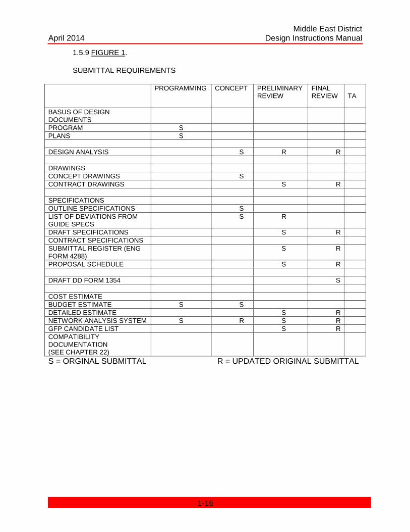
1.5.9 FIGURE 1.
SUBMITTAL REQUIREMENTS
PROGRAMMING CONCEPT PRELIMINARY REVIEW
FINAL REVIEW TA
BASUS OF DESIGN DOCUMENTS
PROGRAM S PLANS S DESIGN ANALYSIS S R R DRAWINGS CONCEPT DRAWINGS S CONTRACT DRAWINGS S R SPECIFICATIONS OUTLINE SPECIFICATIONS S LIST OF DEVIATIONS FROM GUIDE SPECS
S R
DRAFT SPECIFICATIONS S R CONTRACT SPECIFICATIONS SUBMITTAL REGISTER (ENG FORM 4288)
S R
PROPOSAL SCHEDULE S R DRAFT DD FORM 1354 S COST ESTIMATE BUDGET ESTIMATE S S DETAILED ESTIMATE S R NETWORK ANALYSIS SYSTEM S R S R GFP CANDIDATE LIST S R COMPATIBILITY DOCUMENTATION (SEE CHAPTER 22)
S = ORGINAL SUBMITTAL R = UPDATED ORIGINAL SUBMITTAL
1-16
Middle East District April 2014 Design Instructions Manual
CHAPTER 2 PRESENTATION OF DATA
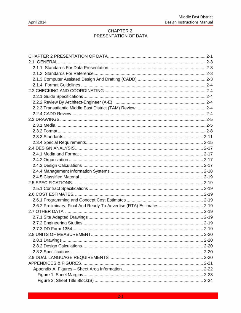
CHAPTER 2 PRESENTATION OF DATA ............................................................................... 2-1 2.1 GENERAL ........................................................................................................................ 2-3
2.1.1 Standards For Data Presentation ............................................................................... 2-3 2.1.2 Standards For Reference........................................................................................... 2-3 2.1.3 Computer Assisted Design And Drafting (CADD) ....................................................... 2-3 2.1.4 Format Guidelines ..................................................................................................... 2-4
2.2 CHECKING AND COORDINATING .................................................................................. 2-4 2.2.1 Guide Specifications ................................................................................................... 2-4 2.2.2 Review By Architect-Engineer (A-E). .......................................................................... 2-4 2.2.3 Transatlantic Middle East District (TAM) Review. ....................................................... 2-4 2.2.4 CADD Review. ............................................................................................................ 2-4
2.3 DRAWINGS ...................................................................................................................... 2-5 2.3.1 Media. ........................................................................................................................ 2-5 2.3.2 Format ........................................................................................................................ 2-8 2.3.3 Standards ................................................................................................................. 2-11 2.3.4 Special Requirements ............................................................................................... 2-15
2.4 DESIGN ANALYSIS. ....................................................................................................... 2-17 2.4.1 Media and Format .................................................................................................... 2-17 2.4.2 Organization ............................................................................................................. 2-17 2.4.3 Design Calculations .................................................................................................. 2-17 2.4.4 Management Information Systems ........................................................................... 2-18 2.4.5 Classified Material .................................................................................................... 2-19
2.5 SPECIFICATIONS. ......................................................................................................... 2-19 2.5.1 Contract Specifications ............................................................................................. 2-19
2.6 COST ESTIMATES. ........................................................................................................ 2-19 2.6.1 Programming and Concept Cost Estimates .............................................................. 2-19 2.6.2 Preliminary, Final And Ready To Advertise (RTA) Estimates .................................... 2-19
2.7 OTHER DATA. ................................................................................................................ 2-19 2.7.1 Site Adapted Drawings ............................................................................................. 2-19 2.7.2 Engineering Studies.................................................................................................. 2-19 2.7.3 DD Form 1354 .......................................................................................................... 2-19
2.8 UNITS OF MEASUREMENT ........................................................................................... 2-20 2.8.1 Drawings .................................................................................................................. 2-20 2.8.2 Design Calculations .................................................................................................. 2-20 2.8.3 Specifications ........................................................................................................... 2-20
2.9 DUAL LANGUAGE REQUIREMENTS ............................................................................ 2-20 APPENDICES & FIGURES ................................................................................................... 2-21 Appendix A: Figures – Sheet Area Information .................................................................. 2-22
Figure 1: Sheet Margins ................................................................................................. 2-23 Figure 2: Sheet Title Block(S) ........................................................................................ 2-24
2-1
Middle East District April 2014 Design Instructions Manual
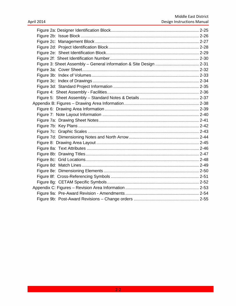
Figure 2a: Designer Identification Block ......................................................................... 2-25 Figure 2b: Issue Block .................................................................................................. 2-26 Figure 2c: Management Block ...................................................................................... 2-27 Figure 2d: Project Identification Block ........................................................................... 2-28 Figure 2e: Sheet Identification Block ............................................................................. 2-29 Figure 2f: Sheet Identification Number .......................................................................... 2-30 Figure 3: Sheet Assembly – General information & Site Design .................................... 2-31 Figure 3a: Cover Sheet ................................................................................................. 2-32 Figure 3b: Index of Volumes ......................................................................................... 2-33 Figure 3c: Index of Drawings ........................................................................................ 2-34 Figure 3d: Standard Project Information ....................................................................... 2-35 Figure 4: Sheet Assembly - Facilities ............................................................................ 2-36 Figure 5: Sheet Assembly – Standard Notes & Details ................................................. 2-37
Appendix B: Figures – Drawing Area Information .............................................................. 2-38 Figure 6: Drawing Area Information .............................................................................. 2-39 Figure 7: Note Layout Information ................................................................................ 2-40 Figure 7a: Drawing Sheet Notes ................................................................................... 2-41 Figure 7b: Key Plans .................................................................................................... 2-42 Figure 7c: Graphic Scales ............................................................................................ 2-43 Figure 7d: Dimensioning Notes and North Arrow .......................................................... 2-44 Figure 8: Drawing Area Layout ..................................................................................... 2-45 Figure 8a: Text Attributes ............................................................................................. 2-46 Figure 8b: Drawing Titles .............................................................................................. 2-47 Figure 8c: Grid Locations .............................................................................................. 2-48 Figure 8d: Match Lines ................................................................................................. 2-49 Figure 8e: Dimensioning Elements ............................................................................... 2-50 Figure 8f: Cross-Referencing Symbols ......................................................................... 2-51 Figure 8g: CETAM Specific Symbols ............................................................................ 2-52
Appendix C: Figures – Revision Area Information ............................................................. 2-53 Figure 9a: Pre-Award Revision - Amendments ............................................................. 2-54 Figure 9b: Post-Award Revisions – Change orders ...................................................... 2-55
2-2

Middle East District April 2014 Design Instructions Manual
CHAPTER 2 PRESENTATION OF DATA
2.1 GENERAL
2.1.1 Standards For Data Presentation. Unless specifically noted otherwise, the standards for data presentation contained in this chapter shall be used in the preparation of all documents required in the contract. All personnel associated with the development and review of drawings, specifications, and other data shall comply with this manual.
2.1.2 Standards For Reference. The Standards for Reference shall incorporate the select requirements of the (1) TAM CADD Procedures, (2) Middle East District Design Instruction, (3) A/E/C CAD Standards and (4) The U.S. National CAD Standard (NCS).
2.1.2.1 TAM CADD Procedures. The TAM CADD Procedures contain specific project information. At the beginning of the design, the A-E is responsible for contacting the CETAM-EN-M to obtain the CADD Procedures, Project Folder Structure and Seed Files.
2.1.2.2 Middle East District Design Instruction Manual. The Middle East District Design Instruction Manual contains supplemental materials and TAM specific requirements not addressed in the A/E/C CAD Standard.
2.1.2.3 A/E/C CAD Standard. The A/E/C CAD Standard contains supplemental materials and DoD specific requirements not addressed in the U.S. National CAD Standard.
2.1.2.4 The U.S. National CAD Standard. The U.S. National CAD Standard is the basis of all CAD standards.
2.1.3 Computer Assisted Design And Drafting (CADD). CADD is required for all design projects. Despite any references called out in the RFP or the contract documents that providing CADD Standards, the CADD Standards in this document will take precedence. The CADD deliverables shall meet the requirements of the following documents in this priority:
(1) TAM CAD Procedures (2) Middle East District Design Instructional Manual Chapter 2: PRESENTATION OF DATA Chapter 22: COMPUTER ASSISTED DESIGN AND DRAFTING (3) A/E/C CAD Standard (4) U.S. National CAD Standard.
All items not specifically addresses in the TAM CAD Procedures shall be referred to Middle East District Design Instruction Manual. Item not covered in the Middle East
2-3

Middle East District April 2014 Design Instructions Manual
Design Instructions Manual shall be referred to the A/E/C Standards. Items not covered by the previous listed CADD Standards shall follow the standards listed in the US National CAD Standards. Any questions regarding the standards to be used should be sent to the MED CADD Department : [email protected].
2.1.4 Format Guidelines. All documents shall be legible and clearly expressed. If the format for a document is not prescribed herein, one shall be chosen by the Architect-Engineer (A-E) to present the data in a uniform and logical manner. Each volume of data required to be submitted by this manual, shall be adequately titled and dated and the name of the submittal stage shall be stamped or otherwise marked on the cover sheet. Pages within a section or chapter of a document shall be consecutively numbered and indexed so that specific items of information can be easily located and referenced.
2.2 CHECKING AND COORDINATING
Documents shall be thoroughly checked and coordinated to prevent the omission of vital information, to discover and resolve conflicts, and to avoid repetition. Since coordination among the design specialties and between the drawings and the specifications is essential, the A-E is encouraged to prepare and use checklists (See Supplement 2 DESIGN CHECKLIST) to assist him in the preparation and in-house checking of his work.
2.2.1 Guide Specifications. Unified Facilities Guide Specification (UFGS) available www.wbdg.org are to be used on all TAM projects unless otherwise noted. These guide specifications contain notes with design information to the specifier and designer. The A-E shall examine these notes and check the drawings and other submittal data to be sure that they are coordinated with the specifications.
2.2.2 Review By Architect-Engineer (A-E). The A-E shall perform an independent review (review by someone other than Designer/Design Engineer) of all drawings, specifications, and other required data prior to the scheduled Final review. This review shall be for the purposes of eliminating errors, interferences, and inconsistencies, and of incorporating design criteria, review comments, guide specifications, and any additional information required by this manual.
2.2.3 Transatlantic Middle East District (TAM) Review. The final review by TAM prior to advertisement of the project, is often limited in time and scope, therefore, the A-E shall not consider any review performed by TAM after the completion of the design effort as justification for incomplete work.
2.2.4 CADD Review. The software program Dr.Checks will be utilized for all review comments. The CADD review shall not be construed as a complete check, but will check for compliance, in accordance with the TAM CADD Procedures, TAM Design Instruction Manual, A/E/C CADD Standards and National CADD Standard.
The CAD review is often limited in time and scope, therefore, the Design Submitter shall not consider any review performed by the Government as an excuse for incomplete work.
2.2.4.1 Shipping CADD Files for Compatibility. The Design Submitter will ship one (1) electronic copy of “Read Only” CADD files no later than thirty (30) calendar days following contract award, to demonstrate compatibility with the CETAM CADD System. (See Section 22.1.4.).
2-4

Middle East District April 2014 Design Instructions Manual
2.2.4.2 Shipping CADD Files for Design Submittals. The Design Submitter will ship one (1) electronic copy of “Read Only” CADD files when providing PDF design submittals.
2.2.4.3 Incorporation of CADD Review Comments. The Design Submitter will be furnished comments from the TAM CADD Management Team. The CADD review will be for the conformance with the technical requirements of this manual. The Design Submitter shall either incorporate each comment or, if the Design Submitter disagrees technically and does not intend to comply with the comment(s), clearly outline with ample justification, its reasons for its noncompliance within five (5) days after receipt of the comment(s).
2.2.4.5 Design Submitter Responsibility. Prior to submittal/re-submittal, all items shall be checked and approved by the Design Submitter Quality Control (QC) System Manager. If found to be in strict conformance with the TAM Design Instruction Manual (DIM), the Quality Control Clause (QCC), will proceed with the submittal.
2.3 DRAWINGS
2.3.1 Media. The elements of Media will address the (1) Approval, (2) Border Sheets, and (3) Plotted Drawings.
2.3.1.1 Approval. Drawings prepared in any convention other than CADD, must have the approval of the CETAM-EN-M. All CADD files must meet the requirements of Chapter 22 of this Design Instruction Manual.
2.3.1.2 Border Sheets. CETAM-EN-M will provide the typical layout for ALL design drawing sheets showing margins, title block information, and zoning.
2.3.1.2.1 Sheet Margins. TAM projects will be prepared for the internationally recognized ANSI “D” size approximately 22 inches by 34 inches. (See Figure(s) 01 – Sheet Margins).
2.3.1.2.1.1 Study Drawings. Study drawings and sketches shall also be prepared when possible on the “A1” size drawing sheets with the title block altered as necessary to permit the signature desired.
2.3.1.2.1.2 Sketches. The revision of amendment sketch form may be on either tracing or bond paper. Lines and lettering shall be dark enough for photographic reproduction process. The A-E shall provide the blank forms as required.
2.3.1.2.2 Sheet Title Block. The Sheet Title Block consists of the (1) Designer Identification Block, (2) Issue Block, (3) Management Block, (4) Project Identification Block, and (5) Sheet Identification Block. (See Figure 02 - Sheet Title Block).
2.3.1.2.2.1 Designer Identification Block. The TAM Logo will consist of the registered USACE Corps Logo and the text stating “US Army Corps of Engineers MIDDLE EAST DISTRICT”. (See Figure 02-A – Designer Identification Block).
2.3.1.2.2.2 Issue Block. The Issue Block consists of the (1) Symbol, (2) Description, (3) Date and (4) Approval sections. (See Figure 02- B – Issue
2-5
Middle East District April 2014 Design Instructions Manual
Block).
2.3.1.2.2.2.1 Symbol. The symbol column will include the percentage of design during the design stage and a delta triangle with the corresponding number or letter inside the triangle representing an Amendment or COP after the award of the design.
2.3.1.2.2.2.2 Description. The Description will include the name of the issue.
2.3.1.2.2.2.3 Date. The Date of issue will be provided in mm- dd-yy format.
2.3.1.2.2.2.4 Approval. The Approval columns will include the initial of the Principal for A-E design work or Project Manager for TAM design work.
2.3.1.2.2.3 Management Block. The Management Block consists of the (1) A-E Name, (2) TAM Name, (3) Designed By, (4) Dwn By, (5) Chk By, (6) Date, (7), Submitted By, (8) File Name, (9) Size, (10) Solicitation Number, (11) Contract Number, (12) Plot Scale and (13) Plot Date. (See Figure 02-C – Management Block).
2.3.1.2.2.3.1 A-E Name. The top half of the left hand side of the management block is reserved for the name of the AE.
2.3.1.2.2.3.2 TAM Name. The bottom half of the left hand side of the management block is reserved for the name of the TAM.
2.3.1.2.2.3.3 Designed By. The designed by block will show the initials of the designer.
2.3.1.2.2.3.4 Dwn By. The drawn by block will show the initials of the detailer.
2.3.1.2.2.3.5 Chk By. The checked by block will show the initials of the checker of the sheet information.
2.3.1.2.2.3.6 Date. The date will show the submittal date in the MM-DD-YY format.
2.3.1.2.2.3.7 Submitted By. The submitted by block will show the principal’s name in the format of initial of first name and complete last name for A-E submittals. TAM submittals will show the names of the respective chiefs as discipline of sheet.
2.3.1.2.2.3.8 File Name. The file number block will show the full MED Design File Number, in coordination with the specific project requirements within the TAM CAD Procedures. (See Section 22.3.2.3.1)
2-6
Middle East District April 2014 Design Instructions Manual
2.3.1.2.2.3.9 Size. The size block will show the text “22 x 34” (See Section 2.3.1.2.1)
2.3.1.2.2.3.10 Solicitation number The solicitation number block will show the Pre-AWARD number.
2.3.1.2.2.3.11 Contract Number. The contract number block will show the AWARD number.
2.3.1.2.2.3.12 Plot Scale. The plot scale block will show the text “FULL” if the 22x34 sheet plotted at 1:1 or “HALF” if the 22x34 sheet plotted at 1:2.
2.3.1.2.2.3.13 Plot Date. The plot date block will show the date when the plots were submitted for submission.
2.3.1.2.2.4 Project Identification Block consists of (1) Project Title, (2) Location of Project, (3) Name of Facility or (4) Name of Drawing Sheet. (See Figure 02 -D – Project Identification Block).
2.3.1.2.2.4.1 Project Title. The Project Title will match the TAM CADD Procedures and will use all capitals letters in its description. No more than (2) lines of text will be used. If the Project Title uses only (1) line, then the bottom title line will be used.
2.3.1.2.2.4.2 P2 Number. The P2 number is a constant number used to track the project from conception to close- out. All newly created projects will include the P2 number.
2.3.1.2.2.4.3 Location of Project. The Location of the Project will match the TAM CADD Procedures and will use all capital letters in its description. No more than (1) line of text will be used.
2.3.1.2.2.4.4 Name of Facility. The Name of the Facility will match the TAM CADD Procedures and will use all capital letters in its description. No more than (1) line of text will be used.
2.3.1.2.2.4.5 Title of the Drawing Sheet will identify the graphical elements found within the drawing area and will use all capital letters in its description. No more than (2) lines of text will be used.
2.3.1.2.2.5 Sheet Identification Block will consist of (1) the Facility Designation Type and (2) the Sheet Reference Number. (See Figure 02-E – Sheet Identification Block).
2.3.1.2.2.5.1 Facility Designation Type. The Facility Designation Type is used to identify the grouping of drawings. The “type” will directly correspond to the Index of Facilities located in the TAM CADD Procedures for each specific project. The Facility Designation Type is NOT part of the Sheet Reference Number. The Facility Designation Type is placed BETWEEN the Sheet ID Text found in the Sheet
2-7

Middle East District April 2014 Design Instructions Manual
Identification Block, AND the actual Sheet Reference Number.
2.3.1.2.2.5.2 Sheet Reference Number. The Sheet Reference Number will appear on all sheets, EXCEPT, the Cover Sheet. It is used to identify discipline type, Sheet Type Designator and Sequential sheet number. Also, depending on the Grouping of Drawings, special requirements will be required for coordination with the Discipline Designator. (See Figure 02-F – Sheet Identification Number).
2.3.1.3 Plotted Drawings. Plotter prepared original drawings shall be prepared on 20 pound bond paper, unless otherwise approved and shall be plotted on the matte side. Raster plotters must provide a minimum resolution of 400 dpi while vector plotters shall provide a minimum resolution of 0.0010 inch with an accuracy of +0.1% of the move and a repeatability error of not more than 0.005 inch. Line density shall be equivalent to that produced by black India ink: half-tones and gray scale plots are not acceptable unless otherwise approved. Manual changes to plotted originals are not acceptable.
2.3.1.3.1 Plotted Drawings for Design Submittals. Plotted Drawings for Design Submittals will be provided in Half Sized sheets. These sheets will use the internationally recognized size of approximately 11 inches by 17 inches. Meeting this requirement allows the design team to;
(1) Accurately verify the graphical scale of the dimensions,
(2) Reduce the desktop space required to review the plots and
(3) Allow for accurate plotting when PDF’s are provided.
2.3.1.4 Binding. All volumes of drawing prints shall be firmly bound and shall have covers of heavier bond than the drawing sheets. If posts are used to fasten sheets together, the drilled holes on the bond edges of the sheets shall be on 8-1/2-inch centers.
2.3.2 Format. The Format will address the (1) General Information, (2) Site Design (3) Facilities and (4) Standard Notes & Details.
2.3.2.1 General Information. General Information sheets consist of the (1) Cover Sheet, (2) Volume Index, (3) Index of Drawings and (4) Standard Project Information. (See Figure 03 Typical Format – General Information & Site Design.)
The General Information sheets consist of the following discipline designator;
Discipline Designation Discipline
G General
2.3.2.1.1 Cover Sheet. The first sheet will be the Cover Sheet. The Cover Sheet is meant to invoke a simple look. It will be comprised of the Project Title, Project City, Project Country, TAM Project Number, Contract Number, Volume
2-8
Middle East District April 2014 Design Instructions Manual
Number, TAM Logo & Info, AE Logo & Info, Submission Type of Submittal and Date of Submittal. (See Figure 03-A – Cover Sheet).
2.3.2.1.2 Index of Volumes. The second sheet will be the Volume Index. A Volume Index will be provided for all submittals, even if only one (1) volume of drawings is required. This sheet will identify the Volume Index as; “Volume 1 of 1” and will list the Site Plan, Name of the Facilities, and/or Standard Facility Notes & Details found in that volume.
(See Figure 03-B – Index of Volumes).
However, when a project consists of more than 250 drawing sheets, the drawing set shall be broken up into subsequent volumes having 200 or less sheets per volume. The Volumes will be identified as “Volume 1 of (X)”, when X= the number of volumes provided.
Note #1; Drawings for a single facility shall NOT be divided between volumes.
Note #2; If there are more than 250 site development drawings, they should be broken into volumes of no more than 200 sheets, but they shall not be broken within a discipline.
2.3.2.1.3 Index of Drawings. The third (and subsequent) sheet(s) will be the Index of Drawings. Multiple Index of Drawings sheets may be required, depending on the project size. The Index of Drawings will list the Drawing Sheets in accordance with the TAM and AEC requirements.(See Figure 03-C – Index of Drawings).
2.3.2.1.4 Standard Project Information. The Standard Project Information sheets will contain standard abbreviations, general legends and the TAM specific Drawing Scales, Drawing Titles and Cross Referencing Symbology. (See Figure 03-D – Standard Project Information).
2.3.2.2 Site Design. Site Design sheets shall consist of the disciplines listed below. (See Figure 03 Typical Format – General Information & Site Design.)
Discipline Designation Discipline
H Hazardous Materials/Environmental
V Surveying/Mapping
B Geotechnical
C Civil
L Landscape
XS Site Structural
2-9
Middle East District April 2014 Design Instructions Manual
XQ Site Equipment
XF Site Fire Protection
XP Site Plumbing
XM Site Mechanical
XE Site Electrical
XT Site Telecommunications
Note #1; Any other non-civil type discipline not listed above, will place an “X” before the discipline designator and be listed in the order in accordance with A/E/C CAD Standard.
2.3.2.3 Facilities. Facility Drawings sheets shall consist of the disciplines listed below. (See Figure 04 - Typical Format – Facilities.)
Discipline Designation Discipline
S Structural
A Architectural
I Interiors
Q Equipment
F Fire Protection
P Plumbing
M Mechanical
E Electrical
T Telecommunications
Z Contractor/Shop Drawings
Note #1; A Facility shall be grouped in the design drawing package so that a single building may be withdrawn without deleting or removing a consecutive block of sheets. Conversely, it shall be possible for the U.S. Army Corps of Engineers to easily add a facility to a bid package.
2.3.2.4 Standard Notes & Details. Typical sheets of Standard Notes & Details used on all buildings are authorized and encouraged. Sheets of Standard Notes & Details may be prepared so that they can be reused if the design package must be divided into separate construction packages. Standard Notes & Details sheets shall consist of the disciplines listed below. (See Figure 05 - Typical Format – Standard Facility
2-10
Middle East District April 2014 Design Instructions Manual
Notes & Details.)
Discipline Designation Discipline
SS Structural
SA Architectural
SI Interiors
SQ Equipment
SF Fire Protection
SP Plumbing
SD Process
SM Mechanical
SE Electrical
ST Telecommunications
Note #1; Notes & Details peculiar to one facility shall NOT be shown in the Standard Facility Notes & Details, but instead within the group of drawings for the facility to which it pertains.
2.3.3 Standards. The Standards will address the information of the (1) Drawing Preparation, (2) Drawing Standards, (3) Layout Information (4) Drawing Layouts and (5) Drawing Revisions.
2.3.3.1 Drawing Preparation. All drawings shall be prepared so that they are well arranged and placed for ready reference, and so that they present complete information. The A-E shall prepare the drawings and specifications with the expectation that both TAM, in the role of supervision, and the construction Contractors will be able to construct the building or facility without any additional assistance from the A-E or the necessity to issue modifications to correct design deficiencies. Drawings shall be complete; however, unnecessary work such as duplicate views, notes and lettering, and repetition of details will not be permitted. Standard details not applicable to the project shall not be shown, and unnecessary waste space shall be minimized. Details of standard products or items which are adequately covered by specifications shall not be included on the drawings. Drawings shall be detailed to the extent that an accurate estimate can be prepared and shop drawings can be checked.
2.3.3.2 Drawing Standards. The Drawing Standards will address the (1) Preparation, (2) Lines and (3) Text.
2.3.3.2.1 Preparation. Preparation of all work shall be for half size reduction unless instructed otherwise. Most modern reproduction processes of half size or smaller do not tolerate shading, whether it be by color or background
2-11

Middle East District April 2014 Design Instructions Manual
shading; therefore, shading shall not be permitted on reproducible material unless otherwise approved. New work shall be clearly distinguished from existing features.
2.3.3.2.2 Lines. Lines shall be opaque and of uniform width for each type of line. The degree of darkness (opacity) shall be the same regardless of the type of line. The difference will be in the width of the line to obtain required variations known as width, weight, density, or gage. Generally, four widths of lines will be used; i.e., thin, medium, thick, and extra thick. These lines shall have widths in the proportion 1:2:4:6; and the appropriate widths will be governed by the size and style of the drawing, always reflecting the more important features more prominently than the secondary or related features. Lines will meet the attribute requirements of the A/E/C CAD Standard. (See Chapter 3 – Graphic Concepts)
2.3.3.2.3 Text. Text shall be displayed in all CAPITALS. Notes will maintain a minimum height/width of 3mm at a 1:1 Sheet Scale. Font Type shall consist of Proportional use of “True Type (TT) Arial”. Text shall be clearly read and not placed over other text. If text is placed in a hatching or patterns, the hatch/pattern area will be clipped so the text can be read.
2.3.3.3 Drawing Area Information. The Drawing Area Information is comprised of the Note Layout Information and Drawing Area Layout Information. (See Figure 07 – Layout Information)
2.3.3.3.1 Note Layout Information. The right hand two-thirds of the sheet shall be favored in the layout of major information since all drawings, when printed, shall be bound on the left. (See Figure 07 – Layout Information)
2.3.3.3.1.1 Drawing Sheet Notes. The Drawing Sheet Notes shall include General Sheet Notes, Reference Keynotes and if necessary Sheet Keynotes. These items shall occupy the right side of the drawing area. The notes should identify, but not overly describe the materials, components, or assemblies. (See Figure 07-A – Drawing Sheet Notes).
2.3.3.3.1.2 Key Plans. Key plans shall be used to relate large scale plans to total floor plans but also to relate individual buildings to complexes of buildings. Key plans shall be drawn in the lower right- hand corner of the drawing area below the Drawing Sheet Notes and shall indicate the relative location of the represented plan area by crosshatching. When a Key plan is used on the plan sheets, it should also be placed on the elevation sheets with elevation symbols indicating the location of each elevation shown on the sheet. (See Figure 07-B – Key Plans).
2.3.3.3.1.3 Graphic Scales. The graphic scales shall follow the specific TAM requirements and will be used for all drawings. Deliberate reduction of these scales, or use of unusual scales shall be avoided. Similar work for all design disciplines shall, whenever possible, be shown at the same discipline. A graphic scale for each of the different Scales used on a drawing shall be placed in the right hand side of the drawing area below the Key Plan and if necessary shall be stacked one above the other. (See Figure 07-C – Graphic Scales).
2-12

Middle East District April 2014 Design Instructions Manual
2.3.3.3.1.4 Dimension Notes. Units of linear dimension shall be millimeters for all building dimensions, and shall be meters for large site plans. Dimensions without a decimal point are millimeters; dimensions with a decimal point carried to one, two, or three places, are meters. Dimensions will use ONLY the arrowhead terminator. Also, a note shall appear on each dimensioned drawing stating “UNLESS OTHERWISE NOTED, LINEAR DIMENSIONS SHOWN ARE IN MILLIMETERS.” (See Figure 07-D – Dimension Units and Direction Arrows).
2.3.3.3.1.5 North Arrow. All plan view drawings shall have a standard north arrow placed adjacent to the view. To maintain a uniform and consistent drawings presentation, the plan view should, if possible, be located to permit the North direction to be at the bottom of the sheet, by the Standard Dimension note. (See Figure 07-D – Dimension Units and Direction Arrows).
2.3.3.3.2 Drawing Area Layout. The right hand two-thirds of the sheet shall be favored in the layout of major information since all drawings, when printed, shall be bound on the left. (See Figure 08 – Drawing Area Layout)
2.3.3.3.2.1 Text Attributes. Refer to section 2.3.3.2.3 Text.
Additional information found on illustration. (See Figure 08-A – Text Attributes).
2.3.3.3.2.2 Drawing Titles. Drawing Titles will appear within the Drawing layout to identify the type of information represented in the drawing layout area. Drawing titles will be used to identify Plans, Elevations, Sections, Details, Schedules, Diagrams and 3D Representations. The Drawing Title will match the Sheet Title found in the Project Information Block. (See Figure 08-B – Drawing Titles).
2.3.3.3.2.3 Grid Location. Horizontal gridlines will show letter designators and vertical gridlines will show number designators. The starting point for the gridlines will begin in the lower left corner of the drawing. (See Figure 08-C – Grid Location).
2.3.3.3.2.4 Match Lines. Site plans or floor plans that cannot be contained within the boundaries of a single drawing area because of sheet size limitations will use match lines to identify these divisions. (See Figure 08-D – Match Lines).
2.3.3.3.2.5 Dimensioning Elements. The TAM Standard is the use of FILLED ARROWHEADS for the dimension terminators. Under no circumstances will architectural ticks be used. The location of the dimensions will be shown at the top and/or right side of the drawing element. Exterior walls of concrete or masonry will be dimensioned to the outside face of the wall. Interior walls will be dimensioned to the centerline of the wall. Vertical sections or elevations will be dimensioned floor to floor. (See Figure 08-E – Dimensioning Elements).
2.3.3.3.2.6 Cross Referencing Symbology. Cross referencing for sections and details shall be based on the sheet reference number showing from where the
2-13
Middle East District April 2014 Design Instructions Manual
item is referenced from.(See Figure 08-F – Cross Referencing Symbology).
2.3.3.3.2.7 TAM Specific Symbols. The symbols used on the drawings shall be in accordance with those assigned for the AEC CAD Standards, EXCEPT as noted. (See Figure 08-G – TAM Specific Symbols).
2.3.3.4 Revisions. Drawing revisions shall be prepared only on the original CADD files. Following submission of the final design, the "original CADD files" resides with the U.S. Army Corps of Engineers, Middle East District (CETAM). The revision shall be fully coordinated with CETAM-EN-M and prepared by the instructions in this manual. TAM personal and/or A-E Firms will follow the SOP for processing the Amendments or Change Orders. (See Chapter 22, Computer-Aided Design & Drafting (CADD), Appendix C – CAD User SOP’s).
2.3.3.4.1 Revision Designations. Amendments (Pre-Awarded Designs) & Change Orders (Post-Awarded Designs) are the TAM User defined portions of the file name. Their use is comprised post-creation of the original file name. They are differentiated by use of “numbers” for Amendments & “letters” for Change Orders.
Note 1: In all cases either the delta “number” or “letter” found in the revision triangle will match the corresponding Amendment or Change Order.
For Example:
• Amendments - designations use numbers “01 thru 99”.
• Change Orders - designations use letters “A thru Z”.
2.3.3.4.2 Drawing Area Revisions. A revision area is required on all sheets. No changes will be made after advertisement unless authorized by TAM for inclusion in an amendment or change order proposal (COP). Prior to changing any drawing issued for bids, a copy of the CADD file shall be made. The triangular symbol is reserved for annotating revisions to the original drawings after issuance to the bidders. This symbol shall not be used otherwise. The triangle shall be placed on the drawing near each revision and a "cloud" drawn around the change and the triangle, on the designated level of the sheet. After making the record reproducible, the "clouds" from the previous change shall be removed so that only the latest revision is emphasized. For Amendment changes during the advertising period, the triangles shall contain a numeric character corresponding to the actual number of revisions on the drawing. For COP changes after award of the bid, the triangle shall enclose an alphabetic character. Note that the clouds from a previous amendment or COP will be removed, but the drawing area will still contain the previous amendment or COP triangle. (See Figure(s) 09-A & B – Drawing Revision Area).
2.3.3.4.3 Sheet Issue Block Revisions. (See Figure(s) 09-A & B – Sheet Issue Block).
2.3.3.4.4 Index of Drawings Revisions. As the drawings in the set are revised,
2-14

Middle East District April 2014 Design Instructions Manual
the latest revision symbol will appear in the "Revisions" column of the index sheet to show which revised drawings are in the package. (See Figure(s) 09-A & B – Index of Drawings).
2.3.4 Special Requirements. The Special Requirements will address the information of the (1) Graphical Information, (2) Floor Elevation & (3) Gross Floor Area.
2.3.4.1 Graphical Information.
2.3.4.1.1 General Information. All General Information (ie; symbols, notes, legends, etc.) will be placed in the 000 Series of the Sheet Type Designator. However in some case, additional legends will be required to be placed on the drawing layout sheet to identify specific information pertaining to that sheet.
2.3.4.1.2 Plans. Plans represent a drawing of a horizontal plane for a specific layout or arrangement. All Plans will be placed in the 100 Series of the Sheet Type Designator.
2.3.4.1.2.1 Civil Plans. Civil plans include site demolition, site improvement, dimension control, grading, paving, and site utilities plan. Contact CETAM-EN-C for specific information regarding Civil Plans.
2.3.4.1.2.2 Structural Plans. Structural plans include the demolition, foundation, and framing plans. Contact CETAM-EN-S for specific information regarding Structural Plans.
2.3.4.1.2.3 Architectural Plans. Architectural plans include the demolition, floor, reflected ceiling plan, and roof plans. Contact CETAM-EN-A for specific information regarding Architectural Plans.
2.3.4.1.2.4 Interior Plans. Interior plans include demolition, furniture, furnishings, fixtures, and equipment plans. These plans are usually drawn on the architectural backgrounds without symbols or dimension layers. Contact CETAM-EN-A for specific information regarding Interior Plans.
2.3.4.1.2.5 Fire Protection Plans. These plans include floor and demolition plans. They define the piping required to connect fixtures, floor and roof drains, fire pumps, fire hose cabinets, sprinkler heads, and other plumbing system. For some industrial projects such as labs and medical facilities, plans include gas, air, vacuum, and special waste piping. Contact CETAM-EN-B for specific information regarding Fire Protection Plans.
2.3.4.1.2.6 Mechanical Plans. Mechanical plans showing demolition of existing components of the mechanical system or the duct, pipe, and heating media layout for new construction and fire suppression are overlaid on the architectural background. For better readability the architectural floor plan is screened back. Mechanical plans must identify same unit designations that appear in schedules, indicate all sections, reference all details, and size louvers and openings. Contact CETAM-
2-15

Middle East District April 2014 Design Instructions Manual
EN-B for specific information regarding Mechanical Plans.
2.3.4.1.2.7 Electrical Plans. Demolition, lighting, power, communications and fire detection constitute the typical electrical plans. Lighting plans define the type and location of light fixtures, switches, smoke detectors, exit lights, speakers, and elements of the fire detection and security systems. Power plans locate all outlets, electrical panels, junction boxes, motors, switch gears, transformers, emergency generators, and other components of the electrical power system. Contact CETAM-EN-E for specific information regarding Electrical Plans.
2.3.4.1.2.8 Telecommunication Plans. Contact CETAM-EN-E for specific information regarding Telecom Plans.
2.3.4.1.3 Elevations. Architectural exterior elevations and partial exterior elevations are developed from the plans they are projected. For smaller projects, window types, building section and wall section symbols may be shown on the plans. For medium and large projects, wall section and window types may be shown on the elevations. Elevations consist of both Exterior and Interior types. All Elevations will be placed in the 200 Series of the Sheet Type Designator.
2.3.4.1.3.1 Exterior Elevations. Building elevations shall be drawn on the sheet so that the main (normally, the front) elevation is located in the lower left corner of the sheet. The elevation drawings shall be placed on the sheet in a clockwise sequence from the main elevation. Match lines should be set at the same location as the plans. Grid lines should be placed only at the corners.
2.3.4.1.3.2 Interior Elevations. Interior elevations are required for kitchens and classrooms (chalkboard and tackboard walls) to show millwork and casework and to indicate the extent of materials where more than one material is scheduled. They are also required for important spaces such as auditoriums, main lobbies, and atria.
2.3.4.1.4 Sections. Section types may include both Building and Wall sections. All Sections will be placed in the 300 Series of the Sheet Type Designator.
2.3.4.1.5 Large-Scale Views. Large-scale views are drawings reproduced at a larger scale to provide more detailed information that cannot be accommodated at the smaller-scaled drawings. Large-Scale Views include Enlarged Floor Plans, Toilet Rooms, Stair Sections and Elevator Shaft Sections. All Large-Scale Views will be placed in the 400 Series of the Sheet Type Designator.
2.3.4.1.6 Details. Details are used to enlarge specifically identified areas found on the plans and sections. Details are divided into three groups – horizontal or plan details, vertical or section details and 3D details. All details will be placed in the 500 Series of the Sheet Type Designator.
2.3.4.1.7 Schedules And Diagrams. Schedules Take a tabular form while diagrams are graphic representations. Both provide a large amount of information in a limited space. Schedules may be placed either in the specifications or on the drawings. Schedules placed in the drawings will be imbedded, contact CETAM-EN-M for more information.
2-16
Middle East District April 2014 Design Instructions Manual
Schedules, Diagrams, Door & Frame Types, Window Types and Partition Types will be placed in the 600 Series of the Sheet Type Designator.
2.3.4.1.8 Not Used. Contact MED for use of 700 Series.
2.3.4.1.9 Not Used. Contact Med for use of 800 Series.
2.3.4.1.10 3D Representations. 3D Representations showing either Axonometric Drawings, Oblique Drawings, Perspectives or Photographs will be placed in the 900 Series of the Sheet Type Designator.
2.3.4.2 Floor Elevations. All building floor elevations shown on the Architectural, Structural, Electrical, and Mechanical drawings shall be given as reference elevations to the finished ground floor elevation. A reference floor elevation of 100.00 will be used for the finished ground floor. Elevations in terms of height above sea level shall be indicated only on site plans.
2.3.4.2.1 Gross Floor Area. The floor plans shall be devoid of any floor area indications. However, on the same drawing sheet with the architectural floor plan (ground floor plan of multiple storied buildings) the gross floor area shall be indicated in tabular form. The breakdown shall comprise of four items: (1) the total for spaces computed at full area, (2) the total for spaces computed at one- half area, (3) the grand total and (4) the allowed areas listed on the DoD Form 1391 for MILCON Projects. The basis of the gross area is the total area of all floors, including mezzanines, basements, and penthouses as determined by the effective outside dimensions of the building. One-half area shall be included for loading platforms and covered, but not enclosed, patios, passageways, porches, balconies; covered and uncovered but open stairs. Uncovered stoops, paved terraces, and all enclosed space having an average ceiling height of less than2.10 meters shall be excluded. Tabulations shall be provided for each floor and then a total gross for the building. For MILCON projects, the total gross area shall not exceed the space allocated on the DoD Form 1391 for the project. Refer to TI800-01 Chapter 5 for building area computation guidance.
2.4 DESIGN ANALYSIS.
2.4.1 Media and Format. The Design analysis shall be presented on 8-1/2- inch by 11-inch paper except that larger sheets may be used when required for graphs or other special calculation forms. All sheets shall be in reproducible form. The material may be typewritten, hand lettered, hand written, or a combination thereof, provided it is legible. Side margins shall be 1-inch minimum to permit side binding and head to head printing. Bottom margins shall be 1-1/4-inches, with page numbers centered 1 inch from the bottom.
2.4.2 Organization. The Several parts and sheets of the design analysis shall be given a sequential binding-number and bound under a cover indicating the name of the facility and project number, if applicable. The title page shall carry the designation of the submittal being made. The complete design analysis presented for final review with the final drawings and specifications shall carry the designation "FINAL DESIGN ANALYSIS" on the title page.
2.4.3 Design Calculations. Design calculations are a part of the design analysis.
2-17
Middle East District April 2014 Design Instructions Manual
When they are voluminous, they shall be bound separately from the narrative part of the design analysis. The design calculations shall be presented in a clean and legible form incorporating a title page and index for each volume. A table of contents, which shall be an index of the indices, shall be furnished when there is more than one volume. The source of loading conditions, supplementary sketches, graphs, formula, and references shall be identified. Assumptions and conclusions shall be explained. Calculation sheets shall carry the names or initials of the computer and the checker and the dates of calculations and checking. No portion of the calculations shall be computed and checked by the same person.
2.4.4 Management Information Systems.
2.4.4.1 Automatic Data Processing Systems (ADPS). When ADPS are used to perform design calculations, the design analysis shall include descriptions of the computer programs used and copies of the ADPS input data and output summaries. When the computer output is large, it may be divided into volumes at logical division points.
2.4.4.2 Computer Printouts. Each set of computer printouts shall be preceded by an index and by a description of the computation performed. If several sets of computations are submitted, they shall be accompanied by a general table of contents in addition to the individual indices.
2.4.4.3 Preparation. Preparation of the description which must accompany each set of ADPS printouts shall include the following.
a. Explain the design method, including assumptions, theories and formulae.
b. Include applicable diagrams, adequately identified.
c. State exactly the computation performed by the computer.
d. Provide all necessary explanations of the computer printout format, symbols, and abbreviations.
e. Use adequate and consistent notation.
f. Provide sufficient information to permit manual checks of the results.
2.4.4.4 Description. The description of each computer program shall be in sufficient detail so that the general method of problem and solution limitations may be identified; however, unless otherwise required by design contract, the A-E is not required to disclose any confidential or proprietary information concerning ADPS that is not normally available to clients without additional charge. Examples of such information are detailed computer programs and machine language. ENG FORM 2883 may be used for this purpose.
2.4.4.5 Specific Requirements. Specific requirements for ADPS material.
a. Disks or tapes used for final computations shall be retained for the life of the construction contract.
b. Final submission shall include a complete set of checked
2-18

Middle East District April 2014 Design Instructions Manual
computations clearly marked as finals.
c. MED will not accept additional printout sheets sent by the A-E to be incorporated with previously submitted computations.
2.4.5 Classified Material. Those Volumes Of the design analysis containing classified material shall be marked and handled in accordance with applicable security regulations. Where only a minor portion of the criteria or calculations is of a classified nature, every effort shall be made to prepare the design analysis so as to permit it to be an unclassified document with proper references to sources of classified material.
2.5 SPECIFICATIONS.
2.5.1 Contract Specifications. Instructions, accompanied by examples for the preparation of the contract specifications, are contained in Chapter 3: SPECIFICATIONS.
2.6 COST ESTIMATES.
2.6.1 Programming and Concept Cost Estimates. The estimates of cost submitted with the Programming and Concept Design Submittals shall be as accurate as possible for they will be used for programming and budgeting purposes and will be a major factor in determining how or if the project is to proceed through the Final design and construction phases. These estimates shall be prepared in pencil, or by computer. See Chapter 4: COST ESTIMATING for format, model estimate, and other instructions.
2.6.2 Preliminary, Final And Ready To Advertise (RTA) Estimates. The Preliminary, Final and RTA estimates shall be prepared in increasing detail by the use of computer assisted techniques, as outlined in Chapter 4: COST ESTIMATING. These estimates will be used in design control and as a basis to negotiate the construction contract.
2.7 OTHER DATA.
2.7.1 Site Adapted Drawings. Construction of various buildings and facilities may be required at sites other than those for which original designs were developed. In order to reuse the drawings for any particular site, the drawings must be adapted to conform to the site requirements, particularly in relation to foundation design. Revision may also be required of the heating system and other utilities, and may include other minor building design changes desired by the user. Such site adaptation shall be made by using the original design drawings to the maximum extent possible. The original titles block will be retained with appropriate changes to the file and sheet numbers. The top line of the revision area shall contain the phrase "Site Adapted For ". The A-E may add his firm's name and the phrase "Site Adapted by" to the drawings at the left edge of the title block.
2.7.2 Engineering Studies. Occasionally, in addition to the items previously mentioned, engineering studies that relate to specific problems and engineering reports thereon are required. The necessary instructions regarding the preparation of such reports will be furnished when required.
2.7.3 DD Form 1354. DD Form 1354(Transfer and Acceptance of Military Real Property) as required under Chapter 1 and attached Sample DD Form 1354.
2-19

Middle East District April 2014 Design Instructions Manual
2.8 UNITS OF MEASUREMENT.
It is the intent of TAM to provide a quality of construction based upon U.S. construction standards. At the same time, our clients use in general, the metric system as the national system of measure. In order to provide projects based on U.S. construction standards and to facilitate the use of the metric system, the following standardized approach will be taken in preparing data.
2.8.1 Drawings. All site layout data shall be dimensioned in meters or coordinates, as appropriate. All details and pipe sizes shall be dimensioned in millimeters.
EXAMPLE: Masonry openings shall be a U.S. module to suit a standard U.S. door. The dimensions of the opening shall be given in metric.
2.8.2 Design Calculations. Calculations shall be in English or metric units as deemed appropriate by the designer to meet the requirements of the design. Quantities on the contract drawings stated in metric units, shall also be stated in metric units in the design analysis to match the drawings.
2.8.3 Specifications.
2.8.3.1 Equipment and Products. Shall be specified by U.S. standards and described by metric units. Specification sections and schedules for sizing and manufacturing of air handling units will state all design requirements in metric units. Specification sections for testing and/or balancing of the system after construction will state all figures in metric units and equivalent English units.
2.8.3.1 Quality of Materials and Equipment. Shall be specified using U.S. standards, such as ASTM Standards, & other industry standards in the guide specifications, unless otherwise instructed by MED.
EXAMPLE: Structural Steel ASTM A 36.
2.9 DUAL LANGUAGE REQUIREMENTS.
Requirements for the use of English and/or another language are found in the following paragraphs. Where both languages are required, English shall always be placed after or below the other language, with the local language dominate.
2.9.1 O&M Manuals. Manufacturers' equipment operation and maintenance manuals shall be required in English only, unless otherwise stated in the contract.
2.9.2 Operating Instructions And Signage. Posted operating instructions, schematics, and signage (including building interior traffic and safety signs) shall be in both the local language and English.
2-20

Middle East District April 2014 Design Instructions Manual
APPENDICES & FIGURES
Appendices:
Appendix A: Figures – Sheet Area Information
Appendix B: Figures – Drawing Area Information
Appendix C: Figures – Revision Area Information
2-21

Middle East District April 2014 Design Instructions Manual
Appendix A: Figures – Sheet Area Information
Sheet Area Information (SAI)
1. Sheet Margins
2. Sheet Title Block
a. Designer Identification Block b. Issue Block c. Management Block d. Project Identification Block e. Sheet Identification Block f. Sheet Identification Number
3. Sheet Assembly – General Info & Site Design
a. Cover Sheet b. Index of Volumes c. Index of Drawings d. Standard Drawing Information
4. Sheet Assembly - Facilities
5. Sheet Assembly – Standard Notes & Details
2-22
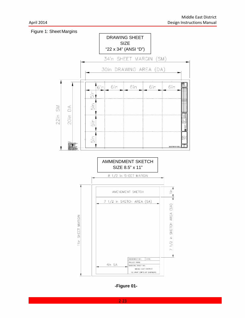
Middle East District April 2014 Design Instructions Manual
Figure 1: Sheet Margins
AMMENDMENT SKETCH SIZE 8.5” x 11”
DRAWING SHEET SIZE
“22 x 34” (ANSI “D”)
-Figure 01-
2-23

Middle East District April 2014 Design Instructions Manual
Figure 2: Sheet Title Block(S)
-Figure 02-
OLD NEW
DESIGNER IDENTIFICATION BLOCK
(SEE FIGURE 02-A)
ISSUE BLOCK
(SEE FIGURE 02- B)
MANAGEMENT BLOCK
(SEE FIGURE 02- C)
PROJECT
IDENTIFICATION BLOCK
(SEE FIGURE 02- D)
SHEET
IDENTIFICATION BLOCK
(SEE FIGURE 02- B)
2-24

Middle East District April 2014 Design Instructions Manual
Figure 2a: Designer Identification Block
FROM DRAWING SHEET SIZE ANSI “D”
LOGO WILL CONSIST OF THE REGISTERED USACE CORPS LOGO
AND TEXT STATING “US Army Corps of
Engineers Middle East District
FONT = TRUE TYPE (TT) ARIAL
HEIGHT & WIDTH = 2.5 mm
-Figure 02-a-
2-25
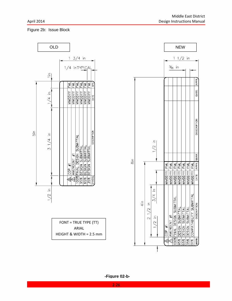
Middle East District April 2014 Design Instructions Manual
Figure 2b: Issue Block
OLD NEW
FONT = TRUE TYPE (TT) ARIAL
HEIGHT & WIDTH = 2.5 mm
-Figure 02-b-
2-26
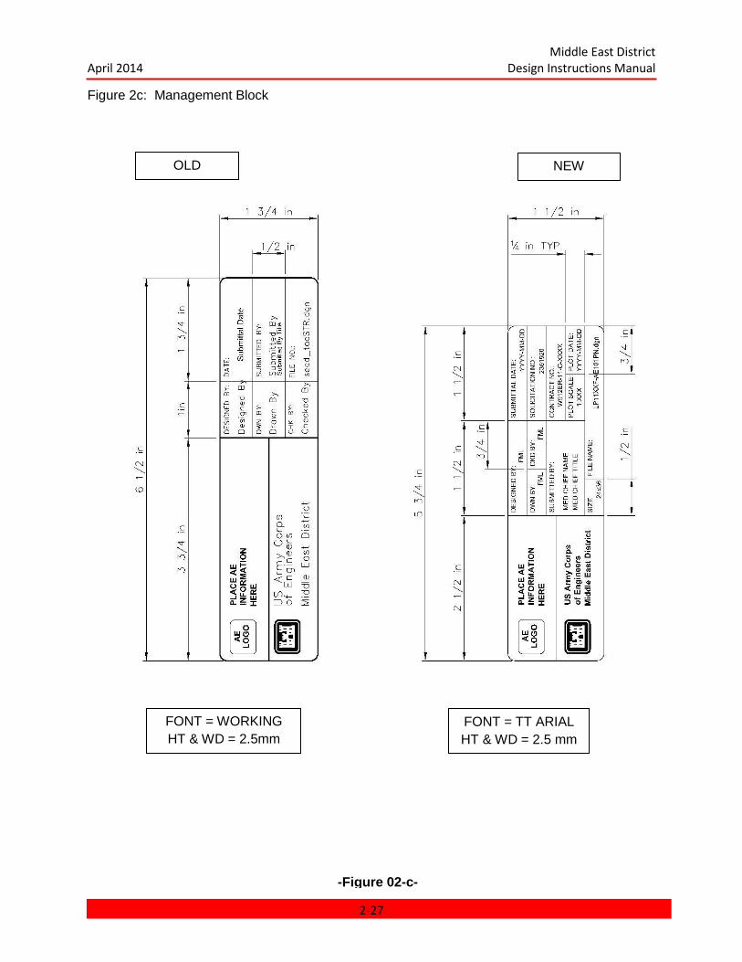
Middle East District April 2014 Design Instructions Manual
Figure 2c: Management Block
-Figure 02-c-
OLD NEW
FONT = WORKING HT & WD = 2.5mm
FONT = TT ARIAL HT & WD = 2.5 mm
2-27

Middle East District April 2014 Design Instructions Manual
Figure 2d: Project Identification Block
-Figure 02-d-
OLD NEW
FONT = WORKING HT & WD = 2.5mm
Except “Project Location”
HT & WD = 2.5 mm
FONT = TT ARIAL HT & WD = 2.5 mm
P2 Number
2-28
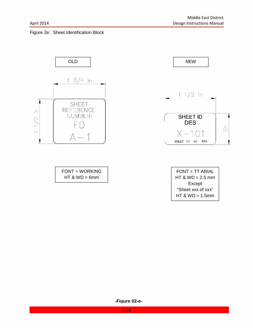
Middle East District April 2014 Design Instructions Manual
Figure 2e: Sheet Identification Block
-Figure 02-e-
OLD NEW
FONT = WORKING HT & WD = 6mm
FONT = TT ARIAL HT & WD = 2.5 mm
Except “Sheet xxx of xxx” HT & WD = 1.5mm
2-29

Middle East District April 2014 Design Instructions Manual
Figure 2f: Sheet Identification Number
Sheet ID Number. The Sheet ID Number will consist of the Discipline Designator, “dash”, Sheet Type Designator and Sheet Sequence Number.
IMPORTANT:
The Facility Folder Designation Type (“A,B,C” etc. for facilities) or (“$” for Standard Details or “-“ for Site Design) is NOT part of the Sheet ID Number.
The Facility Folder Designation Type is placed BETWEEN the Sheet ID Number text found on the border, AND the actual Sheet ID Number.
Site Design Files use a double letter.
The letter “X” precedes the Discipline Designator to identify the sheet as a Site Design.
Facility Folders use a single letter.
A single letter is used to identify the discipline for the sheet for Facility Folders.
Standard Details use a double letter.
The letter “S” precedes the Discipline Designator to identify the sheet as a Standard Detail.
STANDARD DETAILS ARE PLACED AFTER THE LAST FACILITY IN THE INDEX OF DRAWINGS.
“SHEET 01 OF 25” IDENTIFIES HOW MANY SHEETS ARE INCLUDED WITH EACH SPECIFIC DISCIPLINE.
-Figure 02-f-
2-30
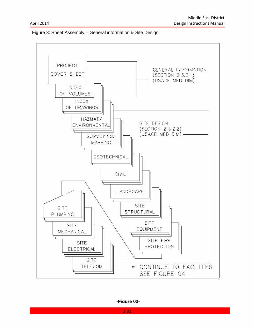
Middle East District April 2014 Design Instructions Manual
Figure 3: Sheet Assembly – General information & Site Design
-Figure 03-
2-31
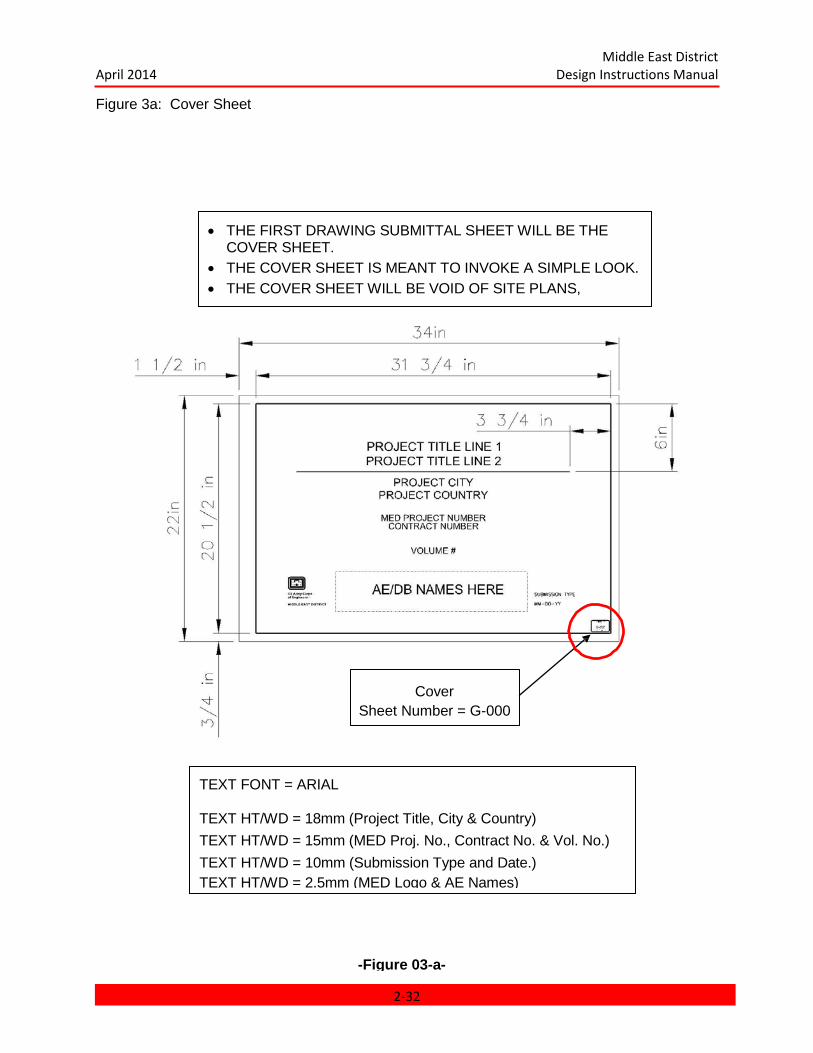
Middle East District April 2014 Design Instructions Manual
Figure 3a: Cover Sheet
• THE FIRST DRAWING SUBMITTAL SHEET WILL BE THE COVER SHEET.
• THE COVER SHEET IS MEANT TO INVOKE A SIMPLE LOOK. • THE COVER SHEET WILL BE VOID OF SITE PLANS,
-Figure 03-a-
TEXT FONT = ARIAL TEXT HT/WD = 18mm (Project Title, City & Country) TEXT HT/WD = 15mm (MED Proj. No., Contract No. & Vol. No.) TEXT HT/WD = 10mm (Submission Type and Date.) TEXT HT/WD = 2.5mm (MED Logo & AE Names)
Cover Sheet Number = G-000
2-32
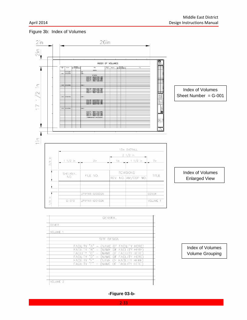
Middle East District April 2014 Design Instructions Manual
Figure 3b: Index of Volumes
-Figure 03-b-
Index of Volumes Sheet Number = G-001
Index of Volumes Enlarged View
Index of Volumes Volume Grouping
2-33
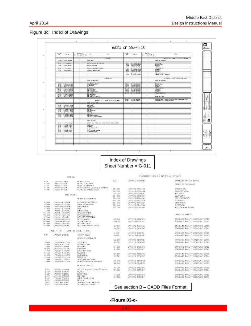
Middle East District April 2014 Design Instructions Manual
Figure 3c: Index of Drawings
Index of Drawings Sheet Number = G-011
See section B – CADD Files Format
-Figure 03-c-
2-34

Middle East District April 2014 Design Instructions Manual
Figure 3d: Standard Project Information
-Figure 03-d-
Standard Legends & Symbology Sheet Sheet Number = G-012
Standard Abbreviation List Sheet Number = G-031
2-35
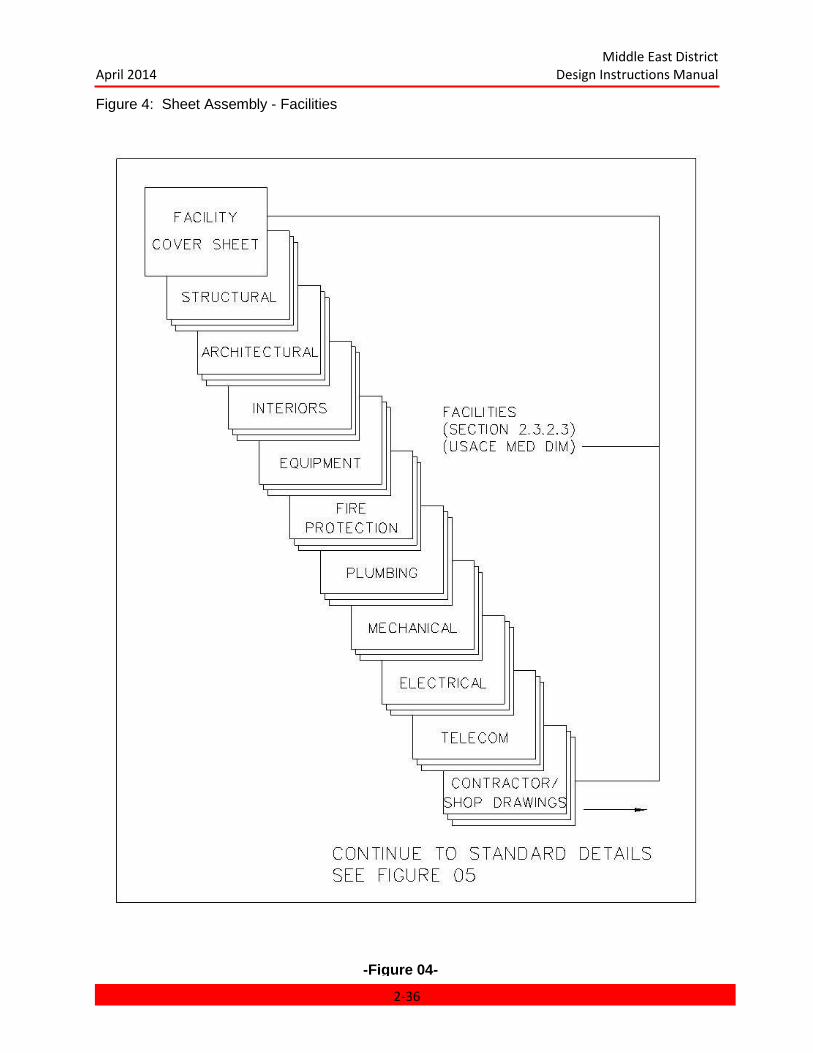
Middle East District April 2014 Design Instructions Manual
Figure 4: Sheet Assembly - Facilities
-Figure 04-
2-36

Middle East District April 2014 Design Instructions Manual
Figure 5: Sheet Assembly – Standard Notes & Details
-Figure 05-
2-37
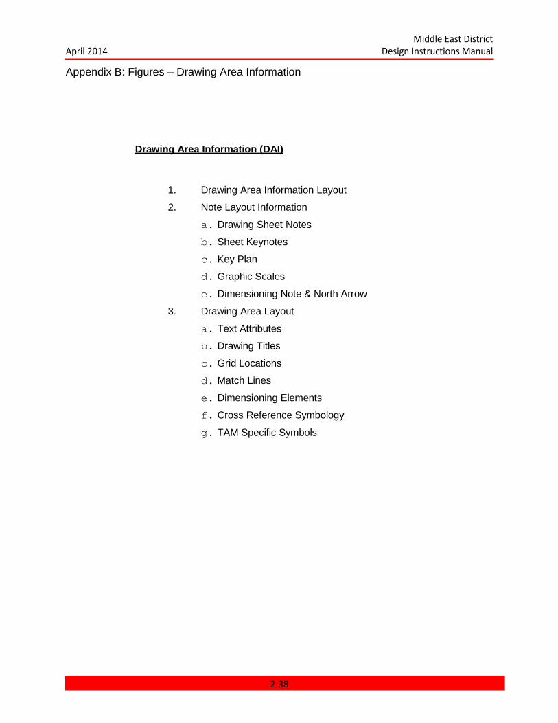
Middle East District April 2014 Design Instructions Manual
Appendix B: Figures – Drawing Area Information
Drawing Area Information (DAI)
1. Drawing Area Information Layout
2. Note Layout Information
a. Drawing Sheet Notes
b. Sheet Keynotes
c. Key Plan
d. Graphic Scales
e. Dimensioning Note & North Arrow
3. Drawing Area Layout
a. Text Attributes
b. Drawing Titles
c. Grid Locations
d. Match Lines
e. Dimensioning Elements
f. Cross Reference Symbology
g. TAM Specific Symbols
2-38
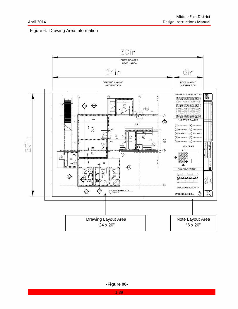
Middle East District April 2014 Design Instructions Manual
Figure 6: Drawing Area Information
-Figure 06-
Drawing Layout Area “24 x 20”
Note Layout Area “6 x 20”
2-39
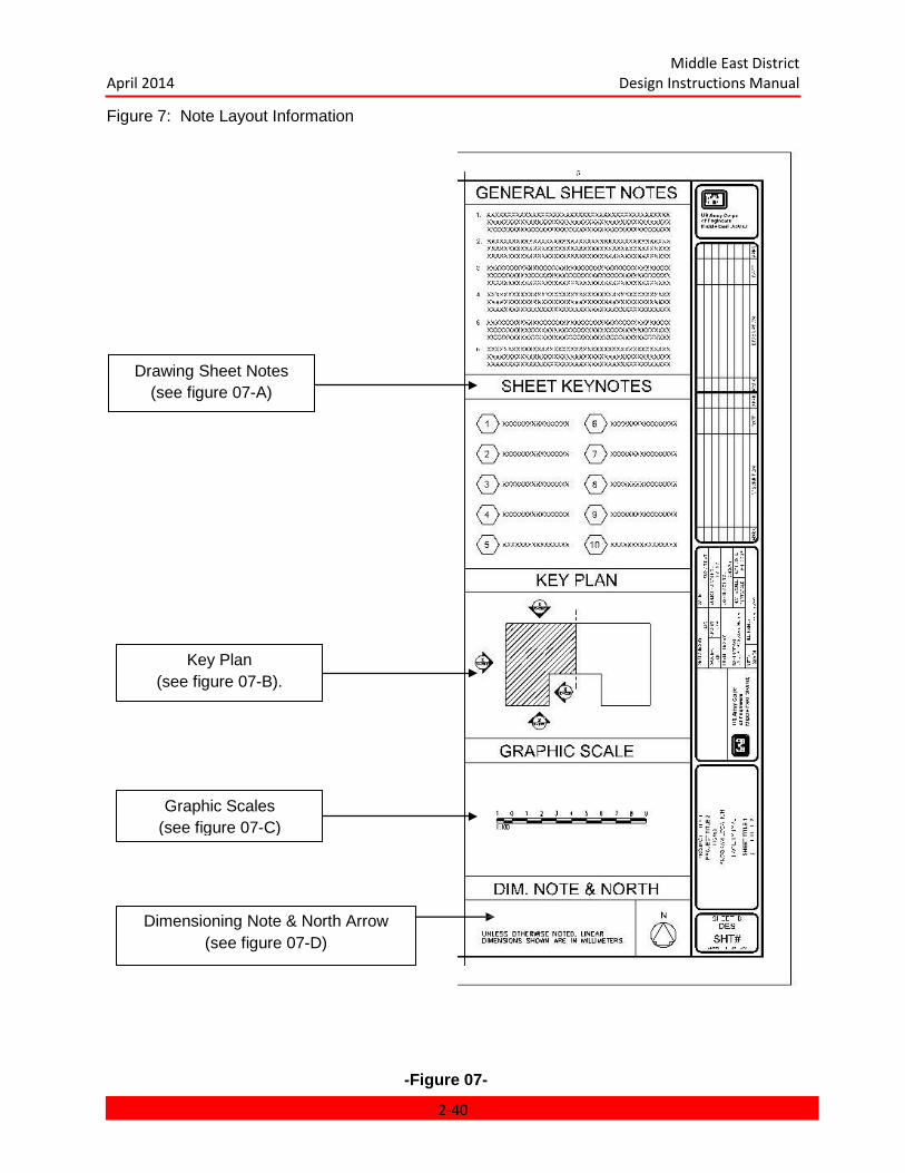
Middle East District April 2014 Design Instructions Manual
Figure 7: Note Layout Information
Dimensioning Note & North Arrow (see figure 07-D)
-Figure 07-
Drawing Sheet Notes (see figure 07-A)
Key Plan (see figure 07-B).
Graphic Scales (see figure 07-C)
2-40
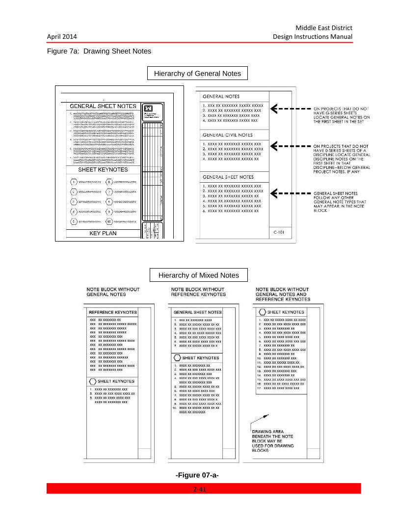
Middle East District April 2014 Design Instructions Manual
Figure 7a: Drawing Sheet Notes
-Figure 07-a-
Hierarchy of Mixed Notes
Hierarchy of General Notes
2-41
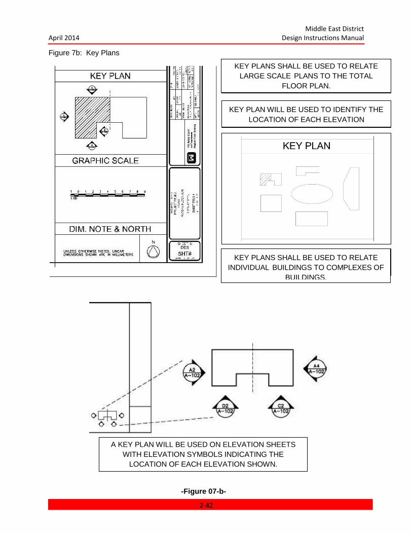
Middle East District April 2014 Design Instructions Manual
Figure 7b: Key Plans
-Figure 07-b-
KEY PLANS SHALL BE USED TO RELATE LARGE SCALE PLANS TO THE TOTAL
FLOOR PLAN.
KEY PLAN WILL BE USED TO IDENTIFY THE LOCATION OF EACH ELEVATION
KEY PLANS SHALL BE USED TO RELATE INDIVIDUAL BUILDINGS TO COMPLEXES OF
BUILDINGS.
A KEY PLAN WILL BE USED ON ELEVATION SHEETS WITH ELEVATION SYMBOLS INDICATING THE
LOCATION OF EACH ELEVATION SHOWN.
2-42
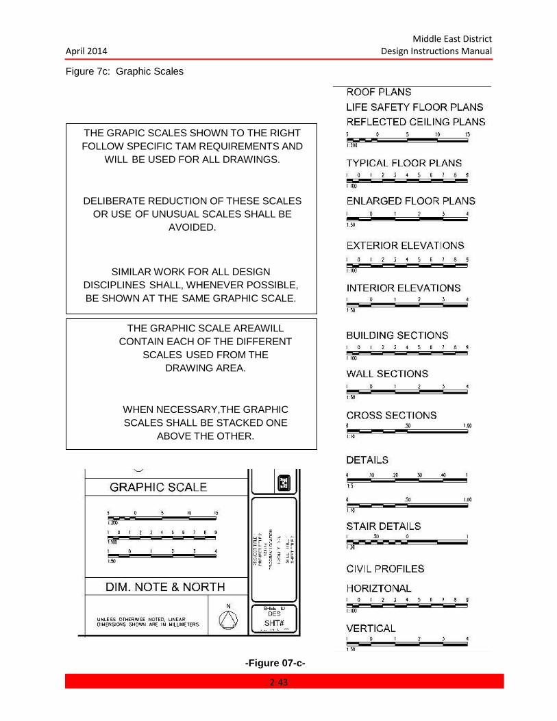
Middle East District April 2014 Design Instructions Manual
Figure 7c: Graphic Scales
-Figure 07-c-
THE GRAPIC SCALES SHOWN TO THE RIGHT FOLLOW SPECIFIC TAM REQUIREMENTS AND
WILL BE USED FOR ALL DRAWINGS.
DELIBERATE REDUCTION OF THESE SCALES OR USE OF UNUSUAL SCALES SHALL BE
AVOIDED.
SIMILAR WORK FOR ALL DESIGN DISCIPLINES SHALL, WHENEVER POSSIBLE, BE SHOWN AT THE SAME GRAPHIC SCALE.
THE GRAPHIC SCALE AREAWILL CONTAIN EACH OF THE DIFFERENT
SCALES USED FROM THE DRAWING AREA.
WHEN NECESSARY,THE GRAPHIC SCALES SHALL BE STACKED ONE
ABOVE THE OTHER.
2-43
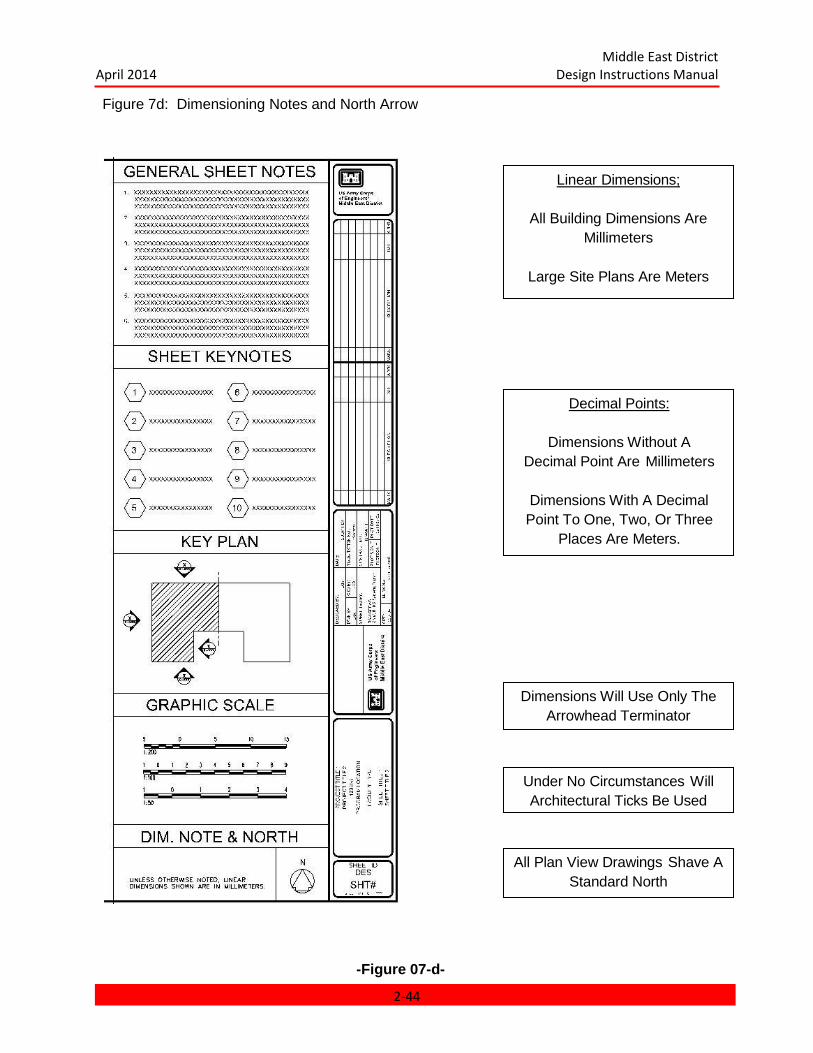
Middle East District April 2014 Design Instructions Manual
Figure 7d: Dimensioning Notes and North Arrow
-Figure 07-d-
Linear Dimensions;
All Building Dimensions Are Millimeters
Large Site Plans Are Meters
Decimal Points:
Dimensions Without A Decimal Point Are Millimeters
Dimensions With A Decimal Point To One, Two, Or Three
Places Are Meters.
Under No Circumstances Will Architectural Ticks Be Used
Dimensions Will Use Only The Arrowhead Terminator
All Plan View Drawings Shave A Standard North
2-44

Middle East District April 2014 Design Instructions Manual
Figure 8: Drawing Area Layout
-Figure 08-
Typical Sheet With Sheet Notes
Plan Sheet (100 Series)
Elevations Sheets (200 Series) Enlarged Plan Sheets (400 Series)
Typical Sheets Without Notes
Section Sheets (300 Series) Detail Sheets (500 Series)
Schedule Sheets (600 Series) Diagram Sheets (600 Series)
3D Sheets (900 Series)
2-45
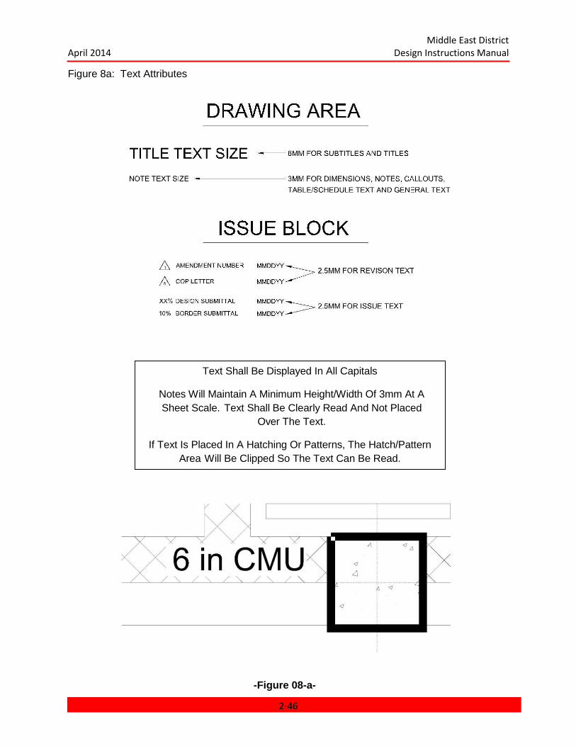
Middle East District April 2014 Design Instructions Manual
Figure 8a: Text Attributes
-Figure 08-a-
Text Shall Be Displayed In All Capitals
Notes Will Maintain A Minimum Height/Width Of 3mm At A Sheet Scale. Text Shall Be Clearly Read And Not Placed
Over The Text.
If Text Is Placed In A Hatching Or Patterns, The Hatch/Pattern Area Will Be Clipped So The Text Can Be Read.
2-46
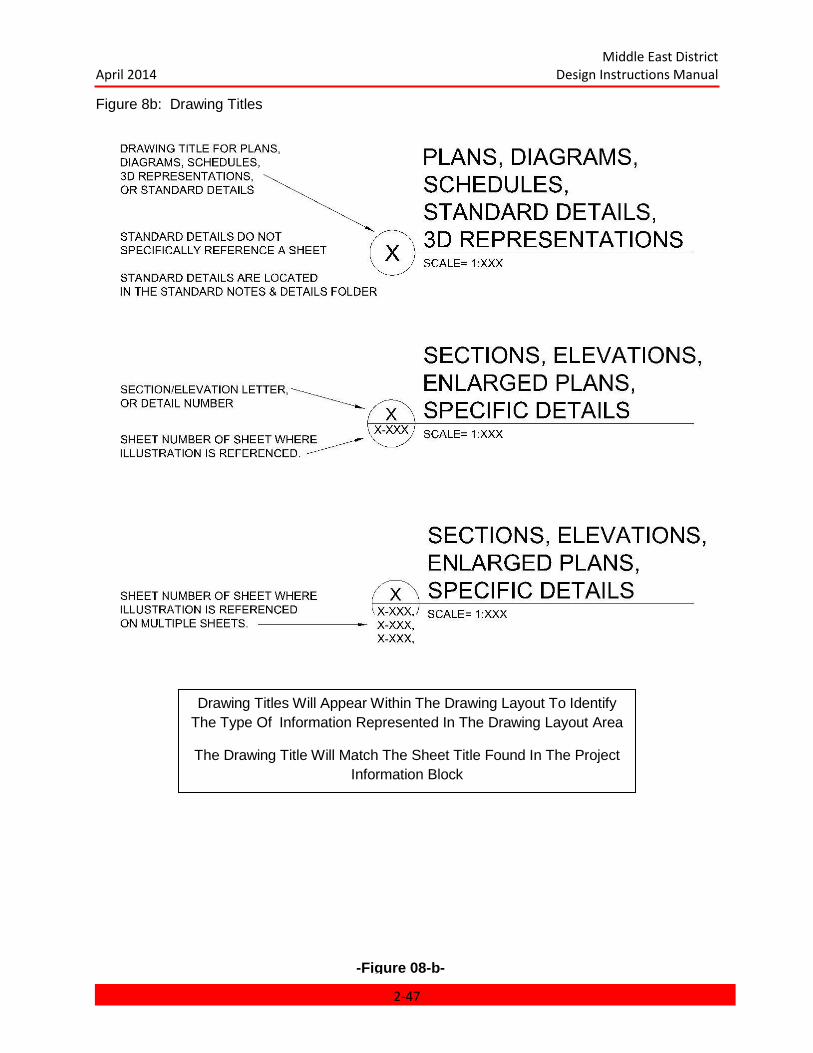
Middle East District April 2014 Design Instructions Manual
Figure 8b: Drawing Titles
-Figure 08-b-
Drawing Titles Will Appear Within The Drawing Layout To Identify The Type Of Information Represented In The Drawing Layout Area
The Drawing Title Will Match The Sheet Title Found In The Project Information Block
2-47
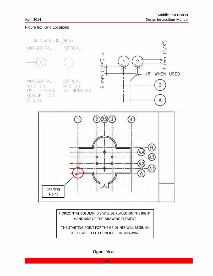
Middle East District April 2014 Design Instructions Manual
Figure 8c: Grid Locations
-Figure 08-c-
HORIZONTAL COLUMN ID’S WILL BE PLACED ON THE RIGHT HAND SIDE OF THE DRAWING ELEMENT
THE STARTING POINT FOR THE GRIDLINES WILL BEGIN IN THE LOWER LEFT CORNER OF THE DRAWING
Starting Point
2-48

Middle East District April 2014 Design Instructions Manual
Figure 8d: Match Lines
-Figure 08-d-
Site Plans Or Floor Plans That Cannot Be Contained Within
The Boundaries Of A Single Drawing Area Because Of Sheet Limitations Will Use Match Lines To Identify These Divisions
Solid Fill Or 45 Degree Hatch Pattern Is
Acceptable
2-49

Middle East District April 2014 Design Instructions Manual
Figure 8e: Dimensioning Elements
-Figure 08-e-
(Med Does Not Use Of Architectural Ticks)
Excerpts Extracted From The National Cad Standards For Reference Only
2-50

Middle East District April 2014 Design Instructions Manual
Figure 8f: Cross-Referencing Symbols
-Figure 08-f-
2-51

Middle East District April 2014 Design Instructions Manual
Figure 8g: CETAM Specific Symbols
-Figure 08-g-
For All Other Symbols Refer To The AEC CAD Standard
(Appendix D – AEC CAD Standard Symbology)
2-52

Middle East District April 2014 Design Instructions Manual
Appendix C: Figures – Revision Area Information
Revision Area Information (RAI)
1. Revision Area Information
a. Pre-Award Revisions - Amendments
b. Pre-Award Revisions – Change Orders
2-53

Middle East District April 2014 Design Instructions Manual
Figure 9a: Pre-Award Revision - Amendments
-Figure 09-a
Drawing Area Revision
Sheet Issue Block
Index Of Drawings
Current Amendment
Previous Amendment
FML = First, Middle Last Name of Project
Manager Responsible for the
Reissue
Previous Amendment
Current Amendment
2-54

Middle East District April 2014 Design Instructions Manual
Figure 9b: Post-Award Revisions – Change orders
-Figure 09-b-
Drawing Area Revision
Index Of Drawings
Current Change Order
Previous Change Order
FML = First, Middle Last Name of Project
Manager Responsible for the
Reissue
Previous Change Order
Current Change Order
Sheet Issue Block
2-55
Middle East District April 2014 Design Instructions Manual
CHAPTER 3 SPECIFICATION
CHAPTER 3 SPECIFICATION ...................................................................................................... 3-1
3.1 GENERAL INSTRUCTIONS ................................................................................................... 3-3
3.1.1 Guide Specifications ......................................................................................................... 3-3
3.1.2 Standard Facility Specifications ........................................................................................ 3-3
3.2 APPLICABLE PUBLICATIONS ............................................................................................... 3-3
3.3 SUBMITTAL REQUIREMENTS .............................................................................................. 3-3
3.3.1 Concept Submittal ............................................................................................................ 3-4
3.3.2 Preliminary Review Submittal ........................................................................................... 3-5
3.3.3 Final Review Submittal ..................................................................................................... 3-5
3.3.4 Ready to Advertise (RTA) Submittal ................................................................................. 3-6
3.3.5 Submittal Review .............................................................................................................. 3-6
3.3.6 Copies Required ............................................................................................................... 3-6
3.4 PREPARATION OF PROJECT SPECIFICATIONS ................................................................. 3-6
3.4.1 Specifications ................................................................................................................... 3-6
3.4.3 Priorities of Publication References .................................................................................. 3-6
3.4.4 Material Descriptions ........................................................................................................ 3-7
3.4.5 New Materials and Methods ............................................................................................. 3-7
3.4.6 Ambiguities ....................................................................................................................... 3-7
3.4.7 Project Table of Contents ................................................................................................. 3-8
3.4.8 Guide specifications.......................................................................................................... 3-8
3.4.9 Edited Guide Specifications .............................................................................................. 3-8
3.4.10 RTA Specifications ......................................................................................................... 3-8
3.4.11 New Sections .................................................................................................................. 3-8
3.5 AMENDMENTS ...................................................................................................................... 3-9
3.5.1 Amendment ...................................................................................................................... 3-9
3.5.2 Scheduling of Amendment ................................................................................................ 3-9
3.5.3 Preparation of Amendments ............................................................................................. 3-9
3.6 CHANGE ORDER PROPOSAL (COP) ................................................................................... 3-9
3.7 SPECIFIC REQUIREMENTS ................................................................................................ 3-10
3.7.1 Government-Furnished Property..................................................................................... 3-10
3-1

Middle East District April 2014 Design Instructions Manual
3.7.2 Removal of Equipment or Materials at Existing Facilities ................................................ 3-10
3.7.3 Shop Drawings and Submittals ....................................................................................... 3-10
3.7.4 Services of Manufacturer's Technical Representatives ................................................... 3-10
3.7.5 Proprietary Items ............................................................................................................ 3-10
3.8 LIST OF EXAMPLES ............................................................................................................ 3-11
EXAMPLE A - Typical Outline Specification............................................................................. 3-13
EXAMPLE B - Marked-Up Draft Guide Specifications .............................................................. 3-17
EXAMPLE C - Final Submittal ................................................................................................. 3-29
EXAMPLE D – Amendment Revised Section .......................................................................... 3-34
EXAMPLE E – Amendment New Section Added ..................................................................... 3-37
EXAMPLE F – ENG Form 4288............................................................................................... 3-50
3-2
Middle East District April 2014 Design Instructions Manual
CHAPTER 3
SPECIFICATIONS
3.1 GENERAL INSTRUCTIONS.
3.1.1 Guide Specifications. Guide specification referenced throughout this Instructions Manual is the Unified Facility Guide Specifications (UFGS), and is to be used in lieu of writing sections where feasible, except when directed to use standard facility specifications. The UFGS is in the Government SPECSINTACT program, and is available at the Whole Building Design Guide(WBDG) Website (http://www.wbdg.org). Architect-Engineer (AE) firms and personnel performing design for CETAM are required to use UFGS. Guide specifications shall be edited for each particular project by making suitable modifications and alterations thereto.
All inapplicable portions of the guide specifications shall be deleted, and where required additional information shall be added and included in the proper part of each section, in the course of editing. Where various alternatives are provided in the guide specifications, the proper alternative for the specific design shall be selected and other alternatives deleted. Where guide specifications allow use of optional materials or methods, options shall be included in the completed specifications to the extent that such material and methods are suitable and available for construction in the country where the project is located.
3.1.2 Standard Facility Specifications. When a standard design with specifications has been developed for repetitive type structures, a copy of the specifications for the standard design will be furnished to the A-E. The standard facility specification shall be adapted and edited as applicable for the particular project, and updated to reflect current guide specifications requirements.
3.2 APPLICABLE PUBLICATIONS.
The following publications of the issues listed below, but referred to thereafter by basic designation only, form a part of this Manual to the extent indicated by the references thereto.
Engineering Regulations:
ER 415-1-10. Construction Contractor Submittal Procedures.
ER 1110-1-8155. Engineering & Design: Specifications.
ER 1110-345-700. Engineering & Design: Design Analysis, Drawings and Specifications.
Engineering Manuals:
EM 385-1-1 Corps of Engineers Safety and Health Requirements.
3.3 SUBMITTAL REQUIREMENTS.
3-3

Middle East District April 2014 Design Instructions Manual
3.3.1 Concept Submittal. An outline specification prepared in accordance with ER 1110-1-8155 and ER 1110-345-700, shall be submitted for the concept design review. An outline specification (See Example A) is required in order to give an overall picture of the systems to be employed in the construction of a project. Along with the outline specification, a list of deviations from the guide specifications shall be included and shall enumerate all design items which are not in accordance with the guide specifications. A justification for a waiver of guide specifications requirements shall be included for each deviation.
3.3.1.1 Outline specifications shall briefly describe the type and quality of construction, and construction materials and equipment contemplated.
a. Purpose:
To provide a listing of specifications intended to be used, with a description of the design.
To provide a brief but comprehensive listing of the systems, materials, and equipment to be specified.
To require the designer to review the intended guide specifications for the systems, materials, and equipment allowed or covered in the guide specifications.
b. Execution:
Outline specifications shall be a part of the concept design submittal only. They will be made a part of the design analysis.
Designers shall develop outline specifications by reviewing the guide specifications. This will improve coordination between the drawings and specifications by reviewing for materials and equipment to be considered, options available, and flagging those items which require original developed specifications.
At the concept review submission, the outline specifications shall be reviewed thoroughly by each applicable design discipline and by the Specifications Engineer for completeness and accuracy of materials, systems and equipment specified (or not specified).
c. Format:
Outline specifications shall include a listing of the specifications to be used in the project. The listing shall include: section number and section title. Outline specifications format shall be in accordance with Example A. Top and side margins shall be 1-inch minimum to permit side binding and head-to-head printing. Bottom margins shall be 1-inch, with page number centered at bottom margin.
3-4

Middle East District April 2014 Design Instructions Manual
3.3.2 Preliminary Review Submittal. Edited draft specifications including the Project Table of Contents shall be submitted CETAM for the preliminary design review (See Example B attached to this chapter).
When a UFGS is not available for the subject matter to be specified, the designer shall develop the specification section. See New Sections paragraph for requirements.
3.3.3 Final Review Submittal. Completely edited draft specifications shall be submitted for the final design review (See Example C attached to this chapter). Final design drawings, specifications, and design analysis constitute a complete design sufficient for bidding and construction. The ONLY effort remaining between FINAL DESIGN and READY TO ADVERTISE is the incorporation of BCOE comments. The design process DOES NOT continue beyond FINAL DESIGN. The following items shall be included for review with this submittal:
a. Specification sections with Project Table of Contents and any attachments for the specifications.
b. A Proposal Schedule indicating complete listing of bid items, units, and quantities, where required by unit pricing.
c. Identification by separate paragraph, of any aspect of the project that must be addressed elsewhere in the contract documents of the intended design package. The designer shall submit this information on a Memorandum to Middle East District, Engineering for review by the PDT and PM.
d. Upon completion of design for each project a guidance memorandum identifying unusual or critical design features and any direct involvement recommended by the designers during construction phase. This will be accomplished for all designs. The memorandum will identify and recommend involvement in certain phases of field inspection and will outline critical areas of the project where more than routine inspection is required. Topics which are anticipated to be covered in the guidance memorandum will be provided as early as possible in project development. At the concept design stage the need for site visits by geotechnical personnel or other designers will be identified so that the costs can be incorporated into the Project Manager’s budget for the project. Each schedule design Submittal will be accompanied by a draft of the guidance memorandum. After completion of final design, during the RFP solicitation/advertisement period, the final guidance memorandum will be published. Project Managers will assure that field office and MED comments are obtained on the early drafts of the memorandum. Care must be taken to insure that the memorandum addresses all unusual or critical items.
e. Shop Drawing Submittal Register is created with SpecsIntact (ENG Form 4288).
f. UFGS Sections 01 42 00 SOURCES FOR REFERENCE PUBLICATIONS and 00 31 10 METRIC MEASUREMENTS shall be used on all projects.
3-5
Middle East District April 2014 Design Instructions Manual
3.3.4 Ready to Advertise (RTA) Submittal. RTA shall incorporate all comments from the final submittal. This submittal will include the technical specifications (See Example C attached to this chapter); the submittal register; a Proposal Schedule showing bid items, units, and quantities; and guidance Memo. CETAM will prepare the bidding information, bid forms, contract clauses, special clauses and other boilerplate information for the intended project.
3.3.5 Submittal Review. Upon completion of the CETAM review at each stage of submittals, the reviewer's comments will be put in Dr Checks, for incorporation into the next required submittal.
3.3.6 Copies Required. The number of copies of specifications required with each submittal will be stated in the Architect-Engineer's Contract. Unless otherwise stated in the A-E's contract, the absolute minimum for design submittals shall be one (1) CD with PDF and Word format copies, and one (1) printed hard copy on 8-1/2" X 11" white bond paper.
3.4 PREPARATION OF PROJECT SPECIFICATIONS.
3.4.1 Specifications: UFGS is in the SPECSINTACT automated system. A-E's and designers will prepare the project specifications in SPECSINTACT unless otherwise directed in the A-E's contract. Specifications shall be furnished to CETAM in the current version of SPECSINTACT.
3.4.2 Content.
3.4.2.1 The technical specifications shall be in sufficient detail so that when used with the project drawings, estimates or bids can be furnished by contractors, material suppliers, or manufacturers on a fair and competitive basis; and construction can be completed without additional specifications except as necessary to deal with unforeseen conditions or to accomplish changes made during construction. Sections shall be prepared in a manner to supplement the project drawings only to the extent necessary. As a general policy, the use of trade names, proprietary items, and the drafting of a specification by adopting a manufacturer's description shall be avoided. To the extent possible, the specifications shall refer to recognized standards and organizations such as ASTM, ANSI, AWWA, etc. Specifications shall include at a minimum, the following items if appropriate:
a. Size or capacity.
b. Materials of construction.
c. Detailed description of equipment construction and function.
3.4.3 Priorities of Publication References. References known to nationally recognized industry and technical society specifications shall be used. References shall be by specific issue; the revision letter, date, or other specific identification shall be included. Availability of publications (where to purchase) is contained in UFG Section 01 42 00 entitled: SOURCES FOR REFERENCE PUBLICATIONS, available on the Whole Building Design Guide (WBDG) website at:
3-6

Middle East District April 2014 Design Instructions Manual
http://www.wbdg.org
3.4.4 Material Descriptions. Except for unique spare parts that are inherently sole source, trade or brand names will only be used as a last resort and only with acceptance of a Justification and Approval (J&A) staffed by the Project Manager (PM)thru the appropriate offices of Middle East District. The naming of a particular commercial product with the words "or approved equal", or adopting verbatim a manufacturer's description of a particular commercial article will not be allowed, unless approved by the Contracting Officer. If approved for use, no less than three (3) manufacturers with complete address, telephone number, fax number, e-mail address, and Point-of-Contact (POC)if known, shall be included within the specification. The specifier shall describe the needs of the design, or the Government with sufficient clarity to apprize prospective bidders of the specific requirements. Every effort shall be made to describe properly in the specifications (and supplement by drawing details, where applicable), the physical, chemical, or performance characteristics of materials, products, or construction methods in a manner to insure full and free competition. This concept also applies to non-unique spare parts where competitive, equivalent items are available (belts, filters, hoses, valves, bearings, lamps, etc.). When the use of brand-name is considered for specifying products or equipment, the following must be complied with; Brand-name or equal descriptions, and other purchase descriptions that permit prospective contractors to offer products other than those specifically referenced by brand name, shall provide for full and open competition and do not require justifications and approvals to support their use. However, the Specifier must meet the requirements of FAR 11.104, and Subpart 6.300, 6.301, 6.302 and 6.302-1. If and when a brand name is used, a generic description describing both the acceptable and unacceptable salient features of the item will accompany the trade name. In accordance with Contract Clause 52.236-5 entitled MATERIAL AND WORKMANSHIP Proposer’s, Offeror’s, and the Construction Contractor may propose substitutions and such substitutions need not be exact duplicates of the products specified. Therefore the specifier shall take special care to identify the salient features that clearly define the essential requirements and appurtenant accessories that will make one product acceptable and another unacceptable. As with sole source products, Brand Name or equal listings shall list no less than three (3) manufacturers with complete address, telephone number, fax number, e-mail address, and Point-of-Contact (POC) (if known) within the specification.
3.4.5 New Materials and Methods. Unusual or new materials or methods of construction may be specified if merit has been established and use has been approved by CETAM. As an aid to proving merit, a handout is available for use in evaluation of new materials, equipment, and methods for military construction; the evaluation handout may be given to producers and suppliers who present their products for inclusion in specifications for military construction. Copies of the evaluation handout may be obtained from HQDA (DAEN-MCE-S) WASH DC 20314.
3.4.6 Ambiguities. Ambiguities shall be avoided in the preparation of specifications. Specific instructions shall be included in the specifications in lieu of the expression "as directed (approved) by the Contracting Officer". Designer should contact the responsible representative of the Engineering & Construction Directorate, Middle East District, to obtain specific information to avoid the necessity for indefinite specification requirements. For example, when material is to be salvaged and stored, the specifications shall state the disposition of such material, e.g. "to be stored in
3-7

Middle East District April 2014 Design Instructions Manual
Building 210" or "in the Base Salvage Yard", rather than "where directed by the Contracting Officer". When ultimate disposition of excess excavated materials, broken concrete, etc., is impossible to determine at the time of the writing of the specifications, the specification should state that the haul will not exceed a stated number of miles when such material can be disposed of on Government controlled property. When disposal of waste material is to be disposed of by the Contractor off the Government property, the specifications shall state, "Waste material shall be disposed of off the Government premises by and at the expense of the Contractor." Where necessary to demolish or move structures, CETAM should be contacted for disposition of material, equipment or the structure in order that detailed instructions may be given in the Technical Specifications, or Contract Clauses.
3.4.7 Project Table of Contents. A Table of Contents for the project specifications shall be prepared in SpecsIntact.
3.4.8 Guide specifications. When editing guide specifications, intent shall be clearly defined and the guide specifications shall be revised accordingly. Specifications shall not be written which leave the burden of intent (interpretation) on the bidders, contractor, or construction personnel administering the contract in the field.
3.4.9 Edited Guide Specifications. Edited guide specifications shall be prepared as shown in Example B. The following rules shall apply:
a. To delete words: Overstrike Appearance shall be used, so a reviewer is able to read what was deleted. (See Example B attached to this chapter).
b. New text will appear underscored, as defaulted by the <ADD> <ADD> tags in SPECSINTACT.
(See Example B attached to this chapter).
3.4.10 RTA Specifications. The RTA specification section shall be submitted as SpecsIntact files and in PDF format.
3.4.11 New Sections. Those sections required in the Technical Provisions where no guide specifications are available shall be prepared and submitted by the designer in accordance with the following guidelines.
3.4.11.1 Format. The format shall be consistent with the requirements for guide specifications as described in this chapter.
3.4.11.2 Shall be provided to CETAM as SpecsIntact files and in PDF files on CD or DVD.
a. Section Numbering and Title: New sections created by the designer shall conform to Construction Specification Institute (CSI) Format Master 2004 which is a detailed breakdown by subject area; individual six-digit numbers for each subject area.
b. Specification Format shall follow the standard format for the UFGS.
c. When editing a guide specification for a project, paragraph numbers shall be
3-8

Middle East District April 2014 Design Instructions Manual
sequential (Do not show as "Not Used", or "Not Applicable"). An exception would be amendments or change order proposals, where the numbers of paragraphs must remain the same as the advertised package. (instructions from Technical Services Branch (CETAM-EN-T)are required).
f. Paragraph Reference. When a paragraph contains a reference to a titled paragraph within the section, the reference will be by paragraph title not paragraph number, “Work shall be in accordance with paragraph PAINT AND COATINGS.”
3.5 AMENDMENTS.
3.5.1 Amendment. During the time a project is being advertised, revisions or corrections to drawings and specifications may become necessary. When directed by the Project Manager by a formal tasker, the designer shall prepare an amendment to the drawings and/or specifications incorporating the required revisions.
3.5.2 Scheduling of Amendment. Amendment revisions shall be prepared and submitted under a strict time schedule in order that revisions can be issued to bidders at the appropriate time during the advertising period. Close coordination with Technical Services Branch (CETAM-EN-T), is required at this time.
3.5.3 Preparation of Amendments. Amendments shall be prepared in the same manner as stated in the paragraph entitled SUBMITTAL REQUIREMENTS hereinbefore. Deleted text will appear over struck, and new text will appear underscored. The solicitation number and amendment numbers positioned below the page number of the revised or new specification section and shall be coordinated with Technical Services Branch (CETAM-EN-T). Paragraphs shall not be renumbered when making deletions by amendment. For example, if a paragraph is deleted, the paragraph number shall remain and shall be noted as "NOT USED". New paragraphs or subparagraphs should always be inserted at the most logical chronological place between existing paragraphs or subparagraphs.
3.5.3.1 Revised Specifications Sections. Revised specification section shall be re-issued in their entirety. (See example D). The first page of the revised section shall state “REVISED BY AMENDMENT NO. XXXX” under the section title.
3.5.3.2. New Specification Sections. New sections added by amendment shall identified as such. The first page of the new section shall state “ADDED BY AMENDMENT NO. XXXX”” under the section title. (See example E)
Editing tags will not be required on a completely new section added by amendment. The table of contents shall be reprinted to reflect the new section added. The Submittal register for the new section shall be printed.
3.6 CHANGE ORDER PROPOSAL (COP)
Requirements for preparation of a COP, shall be in strict accordance with instructions from Technical Services Branch (CETAM-EN-T). Designers are responsible to insure that specific
3-9

Middle East District April 2014 Design Instructions Manual
instructions are received from CETAM, prior to preparation of specifications or drawings for a COP. This requirement is necessary to insure that the latest up-to-date drawing and specification section is being revised. COP's follow the same procedures as amendments.
3.7 SPECIFIC REQUIREMENTS.
3.7.1 Government-Furnished Property. When Government-furnished, Contractor-installed (GFCI) materials or equipment are involved, such Government-furnished shall be listed on a separate list and submitted along with specifications at the Final and RTA submittals. The list shall contain the quantity, item description including manufacturer's make and model number if available, dimensions, cube weight, and power source if applicable, e.g. gas, electric, steam, 120V, 220V, 240V, etc.
3.7.2 Removal of Equipment or Materials at Existing Facilities. Equipment or materials to be removed shall be identified in the scope of work and shall include any special disposal instructions such as store for re-use or return to customer.
3.7.3 Shop Drawings and Submittals. The designer shall identify all required submittals and shop drawings and categorize than for review or information per ER 415-1-10. SPECSINTACT will automatically compile a list of all required submittals and shop drawings for the projects and create the ENG Form 4288 for the project. See example F.
3.7.4 Services of Manufacturer's Technical Representatives shall be included in contract requirements for projects and equipment when required to insure proper installation, start-up and/or training of operation and maintenance personnel. The requirements for these services shall be added in the Technical Specifications only upon approval and coordination with CETAM.
3.7.5 Proprietary Items. Specifying proprietary items shall not be used when alternate available materials, equipment, systems, or processes are acceptable. Middle East District authorization is necessary when specific materials, equipment, systems, or processes are required by design criteria or conditions. The designer making the determination of the essentialness of the proprietary item shall take the following action.
a. Request To Use Proprietary Item: The designer shall submit for approval a request to use the proprietary item with complete justification for its use to the Middle East District project manager prior to inclusion of the proprietary item or material in the design documents. Requests shall be based on a fully justified determination that only that particular product will meet the essential requirements. Any such request shall be made in time to be resolved and approved.
b. Middle East District Approval of Request: If the justification is adequate, CETAM shall take the necessary steps to have the request approved by the Commander.
c. Insertion of Manufacturer Information: Upon approval of proprietary use of the item involved, the make and model number and manufacturer's address and telephone number shall be inserted and followed with the words "no substitutes will be acceptable".
3-10

Middle East District April 2014 Design Instructions Manual
3.8 LIST OF EXAMPLES
The examples found at the end of this chapter illustrating the format to be used are as follows:
EXAMPLE A - Typical Outline Specification
EXAMPLE B - Marked-Up Draft Guide Specifications. (Preliminary Section)
EXAMPLE C – Final Submittal
EXAMPLE D - Amendment Revised Section
EXAMPLE E - Amendment New Section
EXAMPLE F - Submittal Register ENG Form 4288
3-11
Middle East District April 2014 Design Instructions Manual
3-12
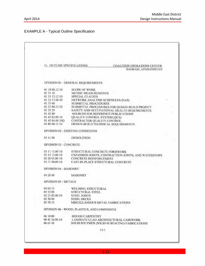
Middle East District April 2014 Design Instructions Manual
EXAMPLE A - Typical Outline Specification
Example A Continued
3-13

Middle East District April 2014 Design Instructions Manual
EXAMPLE A - Continued
3-14
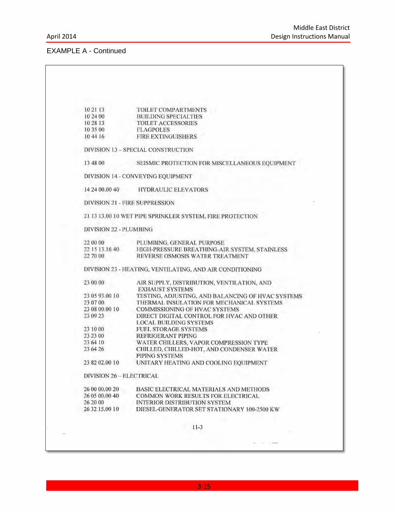
Middle East District April 2014 Design Instructions Manual
EXAMPLE A - Continued
3-15

Middle East District April 2014 Design Instructions Manual
EXAMPLE A - Continued
3-16

Middle East District April 2014 Design Instructions Manual
EXAMPLE B - Marked-Up Draft Guide Specifications
3-17

Middle East District April 2014 Design Instructions Manual
EXAMPLE B - Continued
3-18

Middle East District April 2014 Design Instructions Manual
EXAMPLE B - Continued
3-19

Middle East District April 2014 Design Instructions Manual
EXAMPLE B - Continued
3-20

Middle East District April 2014 Design Instructions Manual
EXAMPLE B - Continued
3-21
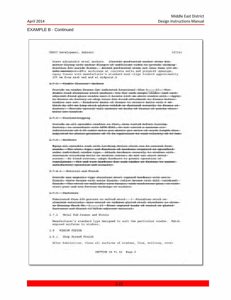
Middle East District April 2014 Design Instructions Manual
EXAMPLE B - Continued
3-22

Middle East District April 2014 Design Instructions Manual
EXAMPLE B - Continued
3-23
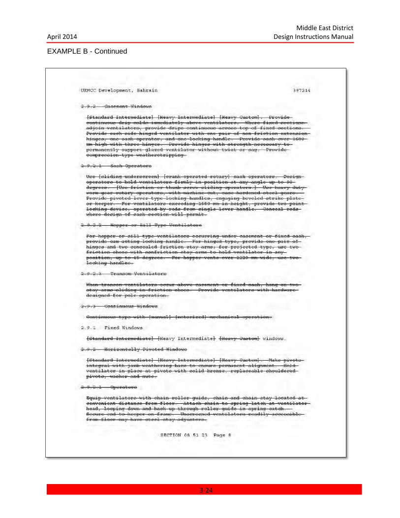
Middle East District April 2014 Design Instructions Manual
EXAMPLE B - Continued
3-24

Middle East District April 2014 Design Instructions Manual
EXAMPLE B - Continued
3-25
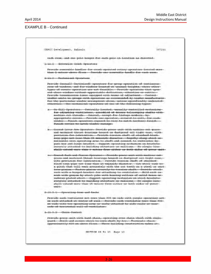
Middle East District April 2014 Design Instructions Manual
EXAMPLE B - Continued
3-26
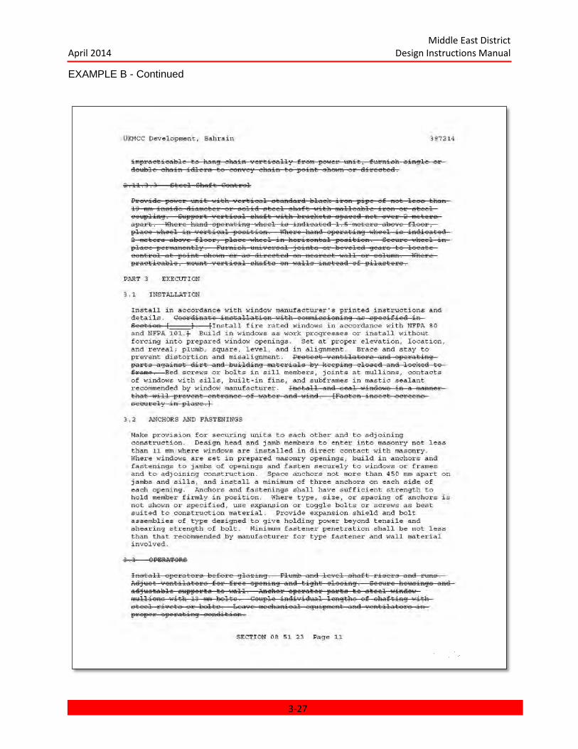
Middle East District April 2014 Design Instructions Manual
EXAMPLE B - Continued
3-27

Middle East District April 2014 Design Instructions Manual
EXAMPLE B - Continued
3-28
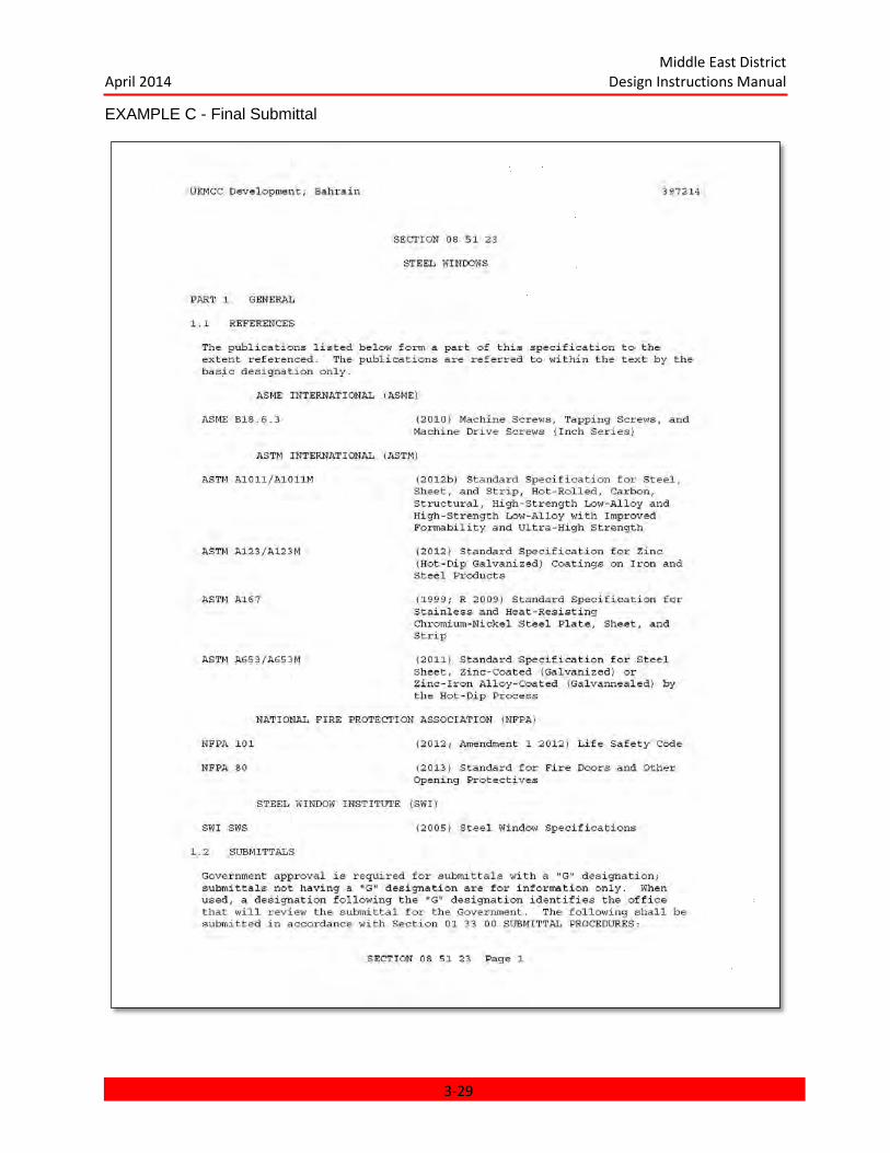
Middle East District April 2014 Design Instructions Manual
EXAMPLE C - Final Submittal
3-29

Middle East District April 2014 Design Instructions Manual
EXAMPLE C - Continued
3-30
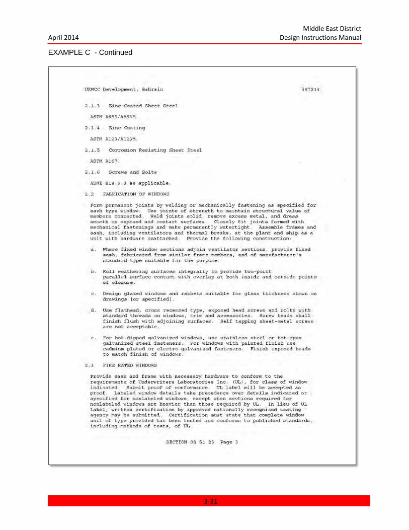
Middle East District April 2014 Design Instructions Manual
EXAMPLE C - Continued
3-31
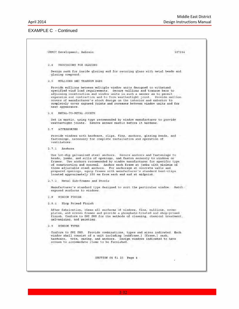
Middle East District April 2014 Design Instructions Manual
EXAMPLE C - Continued
3-32

Middle East District April 2014 Design Instructions Manual
EXAMPLE C - Continued
3-33
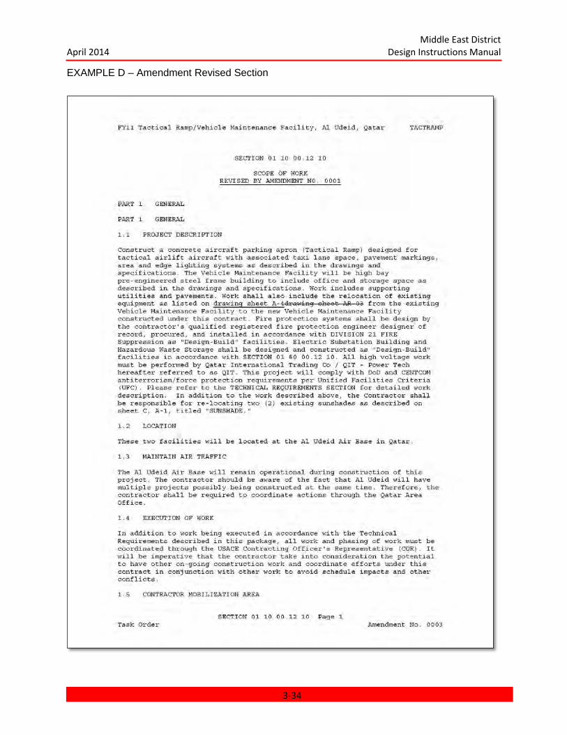
Middle East District April 2014 Design Instructions Manual
EXAMPLE D – Amendment Revised Section
3-34
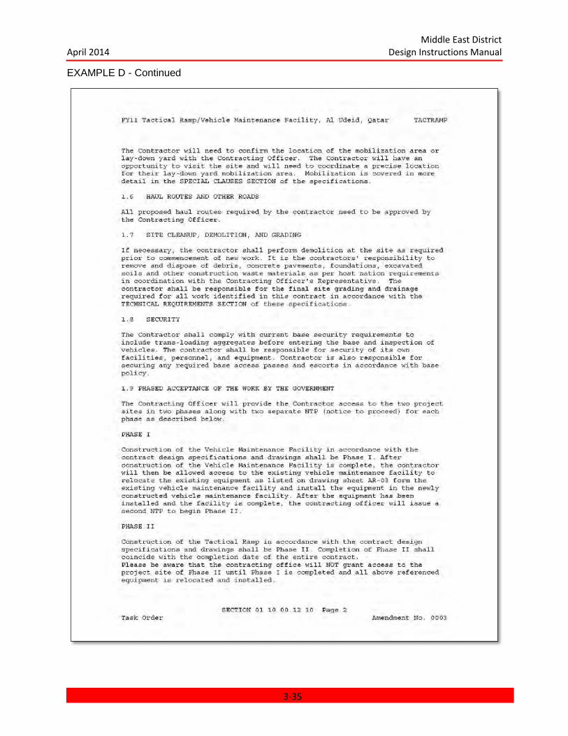
Middle East District April 2014 Design Instructions Manual
EXAMPLE D - Continued
3-35

Middle East District April 2014 Design Instructions Manual
EXAMPLE D - Continued
3-36

Middle East District April 2014 Design Instructions Manual
EXAMPLE E – Amendment New Section Added
3-37
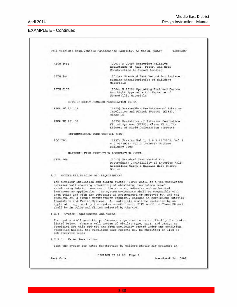
Middle East District April 2014 Design Instructions Manual
EXAMPLE E - Continued
3-38
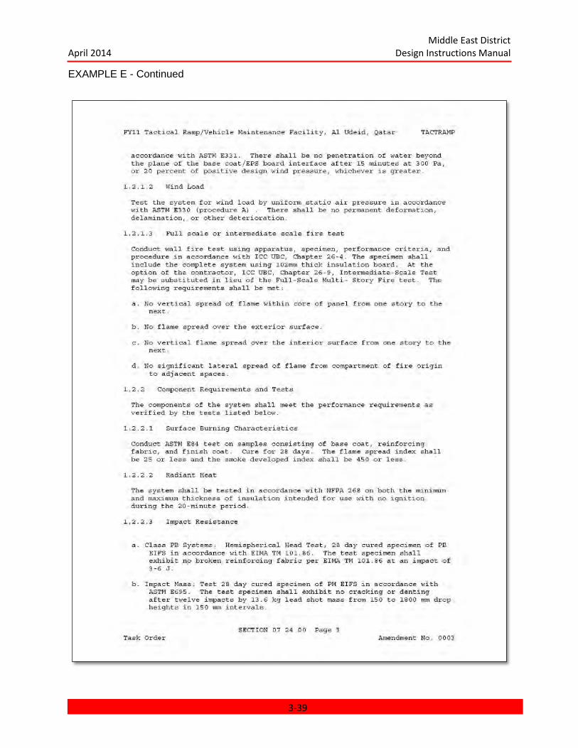
Middle East District April 2014 Design Instructions Manual
EXAMPLE E - Continued
3-39

Middle East District April 2014 Design Instructions Manual
EXAMPLE E - Continued
3-40
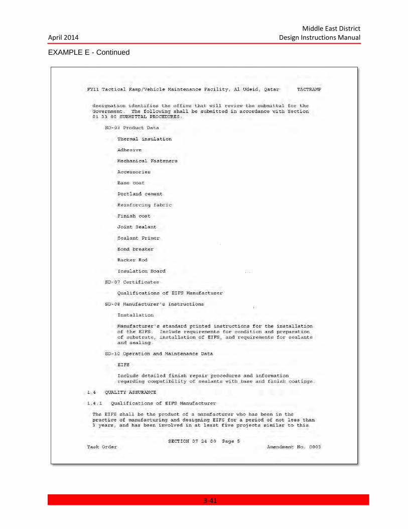
Middle East District April 2014 Design Instructions Manual
EXAMPLE E - Continued
3-41
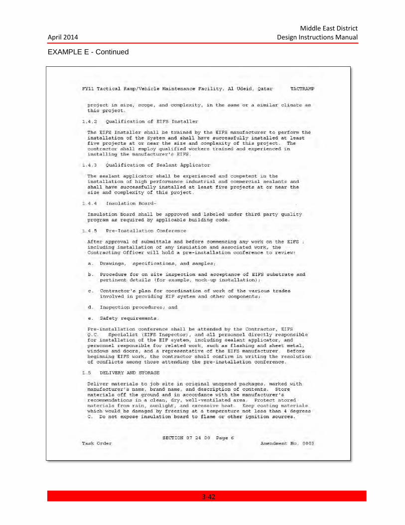
Middle East District April 2014 Design Instructions Manual
EXAMPLE E - Continued
3-42
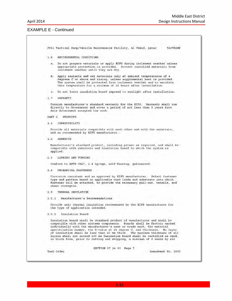
Middle East District April 2014 Design Instructions Manual
EXAMPLE E - Continued
3-43
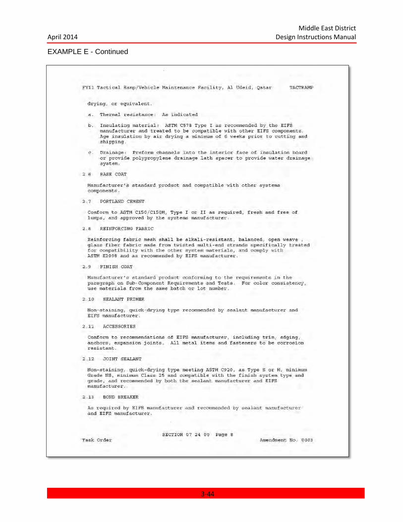
Middle East District April 2014 Design Instructions Manual
EXAMPLE E - Continued
3-44
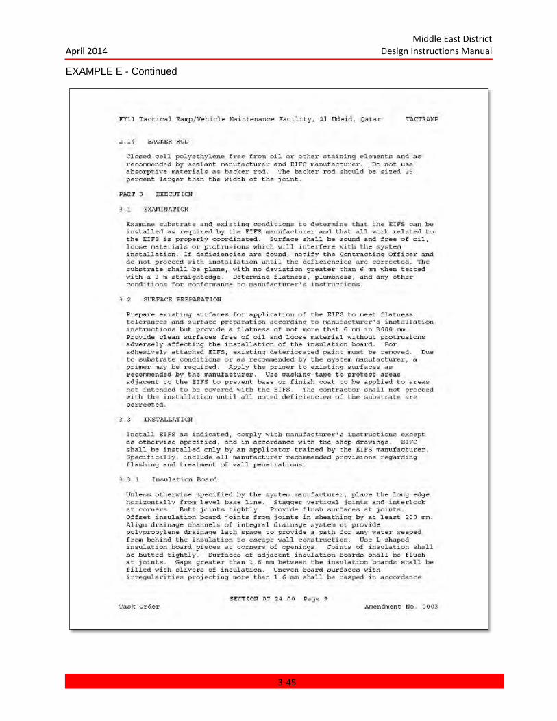
Middle East District April 2014 Design Instructions Manual
EXAMPLE E - Continued
3-45
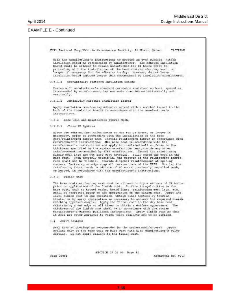
Middle East District April 2014 Design Instructions Manual
EXAMPLE E - Continued
3-46
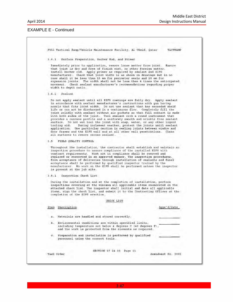
Middle East District April 2014 Design Instructions Manual
EXAMPLE E - Continued
3-47
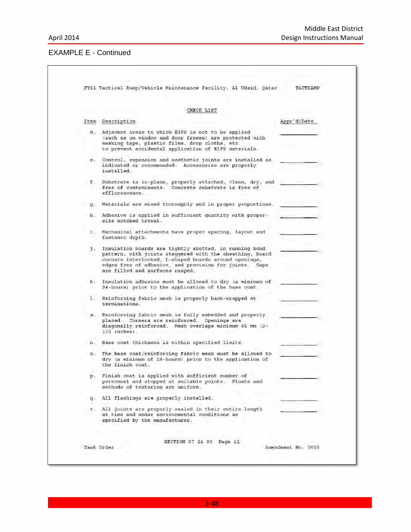
Middle East District April 2014 Design Instructions Manual
EXAMPLE E - Continued
3-48

Middle East District April 2014 Design Instructions Manual
EXAMPLE E - Continued
3-49
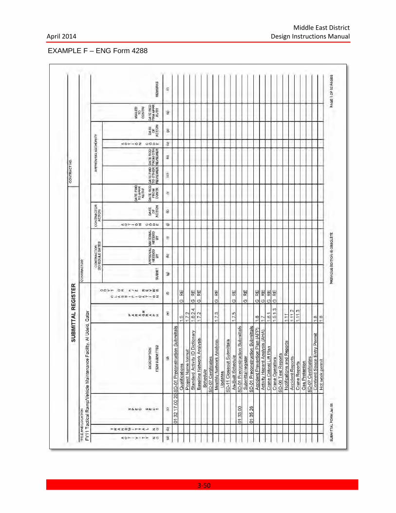
Middle East District April 2014 Design Instructions Manual
EXAMPLE F – ENG Form 4288
3-50
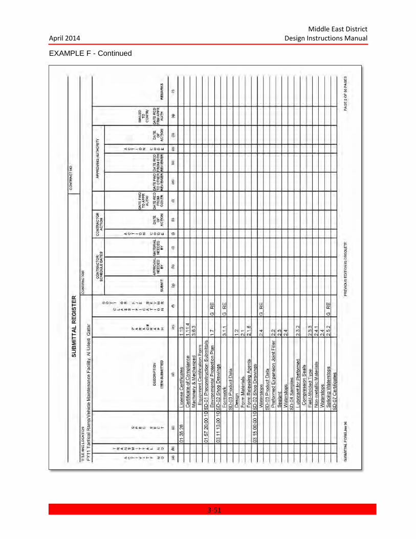
Middle East District April 2014 Design Instructions Manual
EXAMPLE F - Continued
3-51
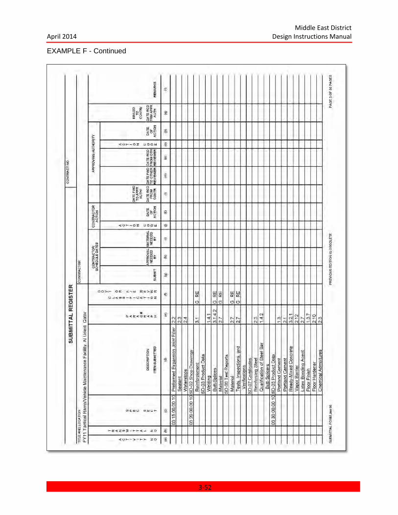
Middle East District April 2014 Design Instructions Manual
EXAMPLE F - Continued
3-52
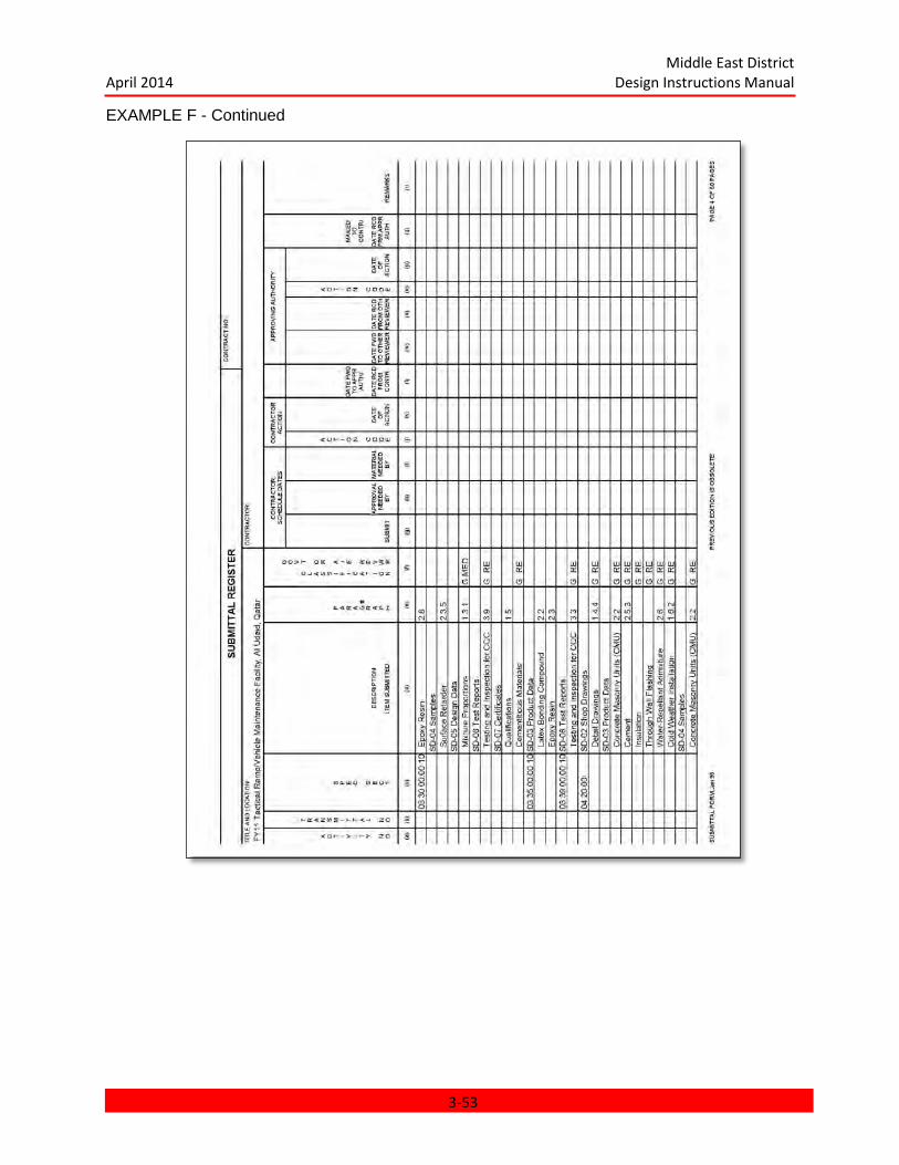
Middle East District April 2014 Design Instructions Manual
EXAMPLE F - Continued
3-53
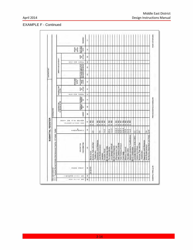
Middle East District April 2014 Design Instructions Manual
EXAMPLE F - Continued
3-54

Middle East District April 2014 Design Instructions Manual
CHAPTER 4 COST ESTIMATING
CHAPTER 4 COST ESTIMATING ................................................................................................................... 4-1 4.1 GENERAL .............................................................................................................................................. 4-2
4.1.1 Purpose ......................................................................................................................................... 4-2 4.1.2 A-E Responsibilities ....................................................................................................................... 4-2
4.2 SUBMITTAL REQUIREMENTS ................................................................................................................ 4-2 4.2.1 Programming and Concept Estimates........................................................................................... 4-2 4.2.2 Preliminary Estimates ................................................................................................................... 4-2 4.2.3 Final and RTA Estimates ................................................................................................................ 4-3
4.3 UNIT PRICE BOOK (UPB) ....................................................................................................................... 4-3 4.4 MANUAL VERSUS COMPUTER TECHNIQUES ....................................................................................... 4-3
4.4.1 Computer Processing .................................................................................................................... 4-3 4.4.2 Manual Estimates.......................................................................................................................... 4-4
4-1

Middle East District April 2014 Design Instructions Manual
CHAPTER 4 COST ESTIMATING
4.1 GENERAL.
4.1.1 Purpose. The purpose of this chapter is to present the general policy of the Middle East District (MED) of the
U.S. Army Corps of Engineers (USACE) concerning cost estimating and to outline the requirements for Architect-Engineers (A-E's) preparing estimates for the Middle East District. Refer to the MED Office Estimating Manual for detailed instructions on preparing estimates and to the MED Unit Price Book for detailed pricing information (Supplement 1, Volumes 1 and 2).
4.1.2 A-E Responsibilities. The A-E shall prepare,(or have prepared by estimating consultants), professional construction cost estimates for the project at the various stages of design as described hereinafter. If review of any estimate submitted indicates noncompliance with these described requirements, i.e., nonprofessional standards, carelessness, or shortcuts which cannot be defended, the A-E shall revise and resubmit the estimate at no additional cost to the Government. If a question is raised against any item in an estimate, the A-E shall provide sufficient data to justify the item. The estimate must be defendable by the A-E. Quantity takeoffs shall be prepared for each line of pricing. These quantity calculations shall be retained by the A-E but shall be presented and defended to MED upon request.
4.2 SUBMITTAL REQUIREMENTS.
Estimates shall be prepared and submitted for each submittal defined in Chapter 1: GENERAL INSTRUCTIONS, i.e., Programming, Concept, Preliminary, Final, and Ready To Advertise (RTA), or as the Scope of Work requires. All pricing shall reflect siting costs.
4.2.1 Programming and Concept Estimates. These estimates shall be prepared using a method agreed upon between the A-E and MED Cost Engineering/Value Engineering Division (CETAM-EN-T). The level of detail shall be commensurate with the amount of design accomplished. The method used may be any one or a combination of the following:
a. Square meter costs experienced overseas facility by type as determined by MED or A-E preparing estimate.
b. Factored U.S. square meter costs for each facility by type with separate factors developed by MED or A-E under MED guidance.
c. Factored U.S. or Outside U.S., experienced square meter cost for systems within a facility, e.g. floors air-conditioning, fire protection, etc.
4.2.2 Preliminary Estimates shall be prepared using a method agreed upon between A-E, and MED (CETAM-EN-T). One of the primary sources of pricing information shall be the MED UNIT PRICE BOOK (UPB) as furnished at the award of the A-E's contract. Preliminary
4-2

Middle East District April 2014 Design Instructions Manual
estimates should be semi-detailed estimates broken down into labor, material, and equipment components, commensurate to the amount of design accomplished. Items for which no design is finished may be estimated using methods as described in subparagraph 4.2.1: Programming and Concept Estimates, hereinbefore. Costs for shipping, indirects, mobilization, demobilization, profit, escalation, etc. shall be applied as a percentage based on MED furnished data supplemented by A-E experience.
4.2.3 Final and RTA Estimates are prepared in a maximum amount of detailed construction tasks, estimated in terms of labor, material, and equipment. The estimates shall be prepared using the Unit Price Book and micro computer techniques as described in Supplement 1, and below. The need for the A-E professional experience is still required. Detailed costs shall be developed for shipping and transportation to the site, mobilization and preparatory work, overhead and indirect costs, profit, and escalation to midpoint of construction. Quotations for major cost items shall be obtained and submitted with the estimates.
4.3 UNIT PRICE BOOK (UPB).
The MED Unit Price Book (UPB), organized by the UCI Uniform Numbering System, contains building construction tasks, daily outputs, unit costs, and shipping information for new construction. A-E's preparing construction cost estimates for MED will be required to use the UPB in conjunction with the instructions in this chapter and the MED Estimating Manual. Information in the UPB shall be used to price either manually prepared estimates or M-CACES estimates. When changes are necessary to pricing in the UPB, the A-E shall document and defend his changes. The responsibility for submittal of a professionally prepared and defendable estimate remains with the A-E.
4.4 MANUAL VERSUS COMPUTER TECHNIQUES.
The A-E Scope of Work will specify whether the direct cost portion of estimates are prepared using manual or computer methods for the various stages of design.
4.4.1 Computer Processing. As specified in the A-E's contract, the direct cost portion of construction cost estimates during the design shall be processed by micro computer on the M-CACES software as outlined in the MED Estimating Manual, Supplement
1. Quantities from the quantity takeoffs shall be entered into the M-CACES software. Code numbers from the MED Unit price Book are then entered corresponding to the quantity takeoff.
4.4.1.1 Processing. At the direction of MED, through the Scope of Work, the A-E shall process a completed computer estimate using MCACES software provided by MED at award of the A-E's contract.
4.4.1.2 Computer Printouts. The computer output sheets or "printouts" will itemize then summarize the direct labor, material, and equipment costs for each building or facility, bid item, and total project. The summaries will also show totals for labor hours by trade,
4-3

Middle East District April 2014 Design Instructions Manual
equipment hours by type, and transportation costs.
4.4.2 Manual Estimates. Use of manual estimates must have approval of Middle East District (CETAM-EN-T). Manually prepared construction cost estimates shall utilize pricing information contained in the MED Unit Price Book. A sample form will be supplied by MED to the A-E.
4-4
Middle East District April 2014 Design Instructions Manual
Chapter 5 PROGRAMMING
CHAPTER 5 PROGRAMMING ............................................................................................... 5-1
5.1 GENERAL ......................................................................................................................... 5-2
5.1.1 Intent .......................................................................................................................... 5-2
5.1.2 Site Selection.............................................................................................................. 5-2
5.1.3 Design Directive ......................................................................................................... 5-2
5.2 APPLICABLE PUBLICATIONS ......................................................................................... 5-2
5.3 PROGRAMMING SUBMITTAL REQUIREMENTS ............................................................ 5-2
5.3.1 Basis of Design Program ............................................................................................ 5-2
5.3.2 Basis of Design Site Plans .......................................................................................... 5-6
5.3.3 Basis of Design Cost Estimate .................................................................................... 5-7
5.3.4 Basis of Design Building Schematic Drawings ............................................................ 5-7
5.4 TECHNICAL REQUIREMENTS ........................................................................................ 5-7
5-1

Middle East District April 2014 Design Instructions Manual
CHAPTER 5
PROGRAMMING
5.1 GENERAL.
5.1.1 Intent. This phase will only be performed when required by the contract. The objective of the programming phase of the work is to prepare the Basis of Design documents to be used in the design of a proposed project. The major tasks facing the Architect Engineer (A-E) during this phase of the work are research and analysis. The A-E, in cooperation with Middle East District (MED), shall define in detail the project purpose, including the activities, processes, and events which will occur at the proposed project. The proposed project site(s) shall be examined, and site conditions shall be analyzed to determine their affinity to the proposed project.
5.1.2 Site Selection. For some projects a number of sites may be considered, in which case the A-E will be charged with a site selection recommendation. The A-E shall investigate each site and make a recommendation based upon the requirements of the proposed project.
5.1.3 Design Directive. The A-E will be given a design directive which will outline the design parameters of the projects as completely as possible, including the purpose of the project, the requirements of the user, the expected time schedule, and the project budget, if determined. The design directive will establish three major parameters for the project: quality, cost, and floor area, and it will determine the relative importance of each. Thus, the design directive will determine whether the project should be a monumental facility with a relatively high cost per square meter, a utilitarian facility with a relatively low cost per square meter, a facility with high quality systems and a subsequent high cost, etc.
5.2 APPLICABLE PUBLICATIONS.
The current edition of the publications listed below, form a part of this manual.
Architectural and Design Criteria (3 July 94) Engineering Instructions (AEI).
5.3 PROGRAMMING SUBMITTAL REQUIREMENTS.
The Basis of Design documents shall be prepared in accordance with Chapter 2: PRESENTATION OF DATA as applicable. The Basis of Design plans should comply with drawing requirements and the Basis of Design Program should comply with design analysis requirements.
5.3.1 Basis of Design Program. The Basis of Design program is a volume of written material which will constitute the main source of project design criteria to implement the later phases of the facility design. The Program shall define the type, purpose, intent and goals of the project and shall assign priorities to any of these stated goals that could be in conflict with each other. The Basis of Design Program shall include but not be limited to the following information:
5.3.1.1 General Requirements. The discussion of the program requirements shall include the following:
a. Purpose: The overall intent and goals together with any background
5-2
Middle East District April 2014 Design Instructions Manual
information necessary to clarify the project.
b. Participants: An overview of the major users of the facilities.
c. Activities: Identification of the significant activities to be supported by the project including relationships between the various activities and any requirements imposed by operational or organizational restrictions.
d. Facilities: The physical features of the project required to meet the functional requirements.
e. General Criteria: User furnished requirements including time schedule, project budget, area limitation phasing requirements, future expansion, etc.
f. Major Assumptions: Requirements augmenting project directive.
5.3.1.2 Intangible Requirements. Determine and express the principal attitudes of the user concerning the character of the whole project and of the individual parts, including outdoor spaces and facilities. Discover the aesthetic qualities desired by the user, indicating the user's preferences for such items as form, scale, density, composition, texture, color, decoration, and other physical characteristics which evoke psychological or sociological responses. The user's evaluation of aesthetic and functional qualities relative to economies of area, cost, and engineering systems shall be expressed. State how these values are different for different project elements and how the user's desires were determined.
5.3.1.3 Facility Requirements. For each facility in the project, the discussion of the program requirements shall include the following:
a General Requirements as identified in paragraph 5.3.1.1 with the discussion directed toward the specific facility.
b. Individual Space Requirements. Develop the information necessary to plan the spaces within the facility as well as any appropriate, specific criteria to be used in the design development. The discussion shall include the following:
1. Function - the purpose of the space, the activities that take place, how often they occur, how long they last, etc.
2. Participants - the people involved in the activities (staff, users, visitors, etc). Their characteristic's (officer, enlisted, civilian, etc) and their number (maximum, minimum, average, etc).
3. Size - the overall area of the space and any allowable variations in space size.
4. Relationships - the requirements for proximity to or remoteness from other spaces.
5. Special considerations - the important features that support the function of
5-3
Middle East District April 2014 Design Instructions Manual
the space, critical dimensions, integral storage requirements, special life safety requirements, etc.
6. Acoustic considerations - the requirements for special sound control measures.
7. Interior requirements - the finishing of the space including identification of major equipment and furniture required to support the activities of the space. Restrictions or requirements on finish, color selection, signage, etc.
8. Structure and Environmental support considerations - requirements relating the building structure; the HVAC, plumbing, fire protection, electrical, and communications systems; etc.
9. Space Development Sketches - any graphic aids necessary to support and/or clarify the space criteria, indicating the important physical features equipment, furniture, etc, required by the activities within the space.
c. Space Allocation Table, relating the functional areas and their programmed space allocations. The table shall include allocations for circulation, mechanical, electrical and other spaces as necessary to yield the total facility gross area as defined in Chapter 2: PRESENTATION OF DATA.
d. Facility Organization. Functional areas shall be organized to obtain the most economical and efficient use of space. Discuss the reasoning behind major layout decisions including such items as optimization of adjacency relationships, establishment of workable and convenient circulation, flexibility of space use, simplification of visual control, economy of structure and/or environmental support systems, etc. Provide any graphic design aids such as affinity drawings, spatial organization and relationship matrices and building layout sketches as necessary to support or clarify the organization of the facility. Comparative analysis of alternate facility organizations considered may be provided where necessary to establish the relative merit of the recommended solution.
5.3.1.4 Site Peculiar Requirements. Site analysis is required for site selection and for project design on the selected site. The discussion shall include the following items.
a. A description of the project site, including boundaries and total area. Include a discussion of any trees, topographic features, and other physical features on the site.
b. An indication of the present and former use of the project site and of the presence of existing structures on it.
c. A discussion of land use on adjacent properties and the characteristics of any surrounding development. Include photographs of significant topographic features such as groves of trees, wadis, escarpments, buildings, etc.
d. A review of any possible conditions of flooding. Describe any significant drainage courses that cross the site.
5-4

Middle East District April 2014 Design Instructions Manual
e. A discussion and an analysis of the surrounding roads, railroads, airports, harbors, towns, outdoor recreation areas and other areas of interest.
f. An inventory of existing mapping and the public services available including public transportation; fire protection; water supply; waste water collection; solid waste collection; electric power and communication systems; and central plant facilities for heating, cooling, water treatment, wastewater treatment, and electrical power.
g. A description of weather conditions at the site: temperatures, rainfall, dust storms, relative humidity, wind conditions, etc.
h. An indication of the orientation of the sun and wind to the site throughout the year. Notes on the wind velocity and wind direction should be included.
i. A summary of the geotechnical conditions at the site; stating the types, elevations, and locations of soils found; the types, elevations, and locations of surface and subsurface rock; soil stability; corrosive elements in the soil; extent and type of subsurface explorations; and any special foundation studies needed for the Concept design.
j. A statement noting the requirements of any existing regional master plan and how the proposed project may comply or conflict with those requirements.
k. A summary of any local zoning regulations, traffic regulations, building restrictions, and any height restrictions due to aircraft landing patterns.
5.3.1.5 Resulting Requirements. The synthesis of the requirements listed above shall be presented. The Basis of Design shall indicate that logical reasoning has been converted into significant design decisions. The information which shall be presented includes the following:
a. Proposed solutions to problems resulting from site conditions.
b. Proposed alternatives for public services which are nonexistent or insufficient, such as water supply and treatment, wastewater treatment and disposal, and power generation and communication systems.
c. Transportation studies, indicating the need, scope and effect of systems for pedestrian, auto, transit, rail and air traffic. From surveys of existing and proposed trip-making, project future trip-making, trip distribution, and modal split.
d. Identification of structures that would have high loading on foundations or excavation for basements.
e. A statement relating to the need to relocate, remodel, or demolish any existing utilities or facilities on the proposed site.
f. If phasing of the project is required, a detailed summary of how the phasing will be handled including how all necessary later phase items will be handled in the initial phase on a temporary basis.
5-5
Middle East District April 2014 Design Instructions Manual
g. An assessment of the impact of the proposed project on the existing environment.
h. Copies of all Corps of Engineers (USACE) standard facility plans or sketches the design A-E is expected to incorporate in the design of the project.
i. A list of all technical publications used to develop this programming information.
5.3.2 Basis of Design Site Plans. The Basis of Design site plans shall provide graphic inventories and analyses of the project site and shall graphically present the proposed project master plan. These site plans shall indicate the major project elements (i.e. structures, circulation, grading and landscaping, and utility services) arranged in accordance with the following parameters: function, appearance, safety, economy, environmental harmony, regional congruity, and future growth. The site plans shall include and shall be limited to the following plans.
5.3.2.1 Existing Site Plan. This plan shall show the existing land use of the site, the existing topography, and the location of any natural or manmade features.
5.3.2.2 Regional and Vicinity Map. This plan shall show the development and other conditions surrounding the site.
5.3.2.3 Site Analysis. This plan shall be the A-E's analysis of the existing site and shall include these items:
a. Best views, poor views, objectionable views.
b. Recommendations for the removal or preservation
of any trees.
c. Areas suitable for development, logical points
of ingress.
d. Prevailing wind and breezes.
e. Assessment of other natural features.
f. Floor elevations, if pertinent.
5.3.2.4 Preliminary Land Use Plan. This plan shall show how the land area of the site is to be developed in terms of general land use. The plan shall also show what relationships exist between the various land-use elements and how much space is allocated for each use.
5.3.2.5 Traffic Circulation Plan. This plan shall show the modes and relative amounts of expected traffic between various elements of the plan and to locations beyond the site. Graphic devices, such as arrow size and line weight, shall be used to indicate sequence, frequency, and volume.
5.3.2.6 General Site Plan. This plan shall show the location of all required facilities, including buildings, parking areas, and roadways. Buildings shall be shown in outline only with
5-6

Middle East District April 2014 Design Instructions Manual
an indication of the number of building floors. Pedestrian and service access points shall be indicated but interior spaces shall not be developed. Parking areas shall be shown only as areas with an indication of the number of parking spaces. Traffic aisles and parking stalls shall not be shown. Only major roads and service access roads shall be shown at this stage. Any major pedestrian routes between buildings shall be shown. Areas with a large number of small buildings such as family housing areas shall be shown only as masses. The probable locations of such facilities as mosques, markets, schools, and major access roads shall be indicated within these mass areas.
5.3.3 Basis of Design Cost Estimate. This estimate shall be used to establish a programming budget to guide the later phases of the facility design. The estimate shall be as described in the Chapter 4: COST ESTIMATING.
5.3.4 Basis of Design Building Schematic Drawings shall be developed based on the Basis of Design Program. Schematics shall be single line drawings at a scale to clearly show the arrangement of the facilities. Dimensions shall be approximately correct, but not necessarily final.
5.3.4.1 Floor plans shall show functional layout of all elements including circulation spaces, entrances, stairways, elevators, column locations, and mechanical and electrical equipment spaces. All rooms and spaces shall be identified but door swings, windows, plumbing fixtures and materials need not be identified. On the first plan of each facility, the gross areas of the facility with a breakdown by floor shall be shown.
5.3.4.2 Elevations shall be block outlines and breaks to indicate the various masses and how they coincide with the plans. Typical proposed window arrangement and exterior material indication shall be shown only to the extent necessary to suggest a possible design in accordance with the program requirements. Floor to floor dimensions shall be shown.
5.3.4.3 Building sections shall show how the architectural, structural, mechanical and electrical systems will be accommodated. Major rooms identified by name shall be shown, as well as floor to floor dimensions.
5.3.4.4 Perspectives shall be consistent in detail and scale with other sketches and shall be provided where desirable to clarify or highlight exterior features of the facilities.
5.4 TECHNICAL REQUIREMENTS.
Programming shall comply with the requirements of Architectural and Engineering Instructions (AEI) Design Criteria as well as the applicable requirements of this volume and the Design Checklist.
5-7

Middle East District April 2014 Design Instructions Manual
CHAPTER 6 SITE PLANNING AND LAYOUT
CHAPTER 6 SITE PLANNING AND LAYOUT ........................................................................ 6-1
6.1.1 Scope ......................................................................................................................... 6-2 6.1.2 Policy .......................................................................................................................... 6-2 6.1.3 Project Specific Criteria .............................................................................................. 6-2
6.2 APPLICABLE PUBLICATIONS ......................................................................................... 6-2 6.3 CONCEPT SUBMITTAL REQUIREMENTS ...................................................................... 6-3
6.3.1 Concept Design Analysis ............................................................................................ 6-4 6.3.2 Concept Design Drawings .......................................................................................... 6-5
6.4 PRELIMINARY SUBMITTAL REQUIREMENTS................................................................ 6-6 6.4.1 Preliminary Design Analysis ....................................................................................... 6-6 6.4.2 Preliminary Design Drawings ...................................................................................... 6-7
6.5 FINAL SUBMITTAL REQUIREMENTS ............................................................................. 6-8 6.5.1 Design Analysis .......................................................................................................... 6-8 6.5.2 Drawings .................................................................................................................... 6-9
6.6 READY TO ADVERTISE (RTA) SUBMITTAL REQUIREMENTS ...................................... 6-9 6.7 TECHNICAL REQUIREMENTS ........................................................................................ 6-9
6.7.1 Buildings and Structures ............................................................................................. 6-9 6.7.2 Fences and Walls ....................................................................................................... 6-9 6.7.3 Circulation .................................................................................................................. 6-9 6.7.4 Airfield Facilities ........................................................................................................ 6-10 6.7.5 Grading..................................................................................................................... 6-11 6.7.6 Landscaping ............................................................................................................. 6-12 6.7.7 Outdoor Recreation .................................................................................................. 6-12
6-1

Middle East District April 2014 Design Instructions Manual
CHAPTER 6
SITE PLANNING AND LAYOUT
6.1 GENERAL.
6.1.1 Scope. This chapter provides guidance for site planning and layout and directs the preparation of site development drawings, specifications, and the design analysis. Specific submittal requirements in this chapter supplement the requirements of Chapter 1: GENERAL INSTRUCTIONS. Drawings, specifications, and the design analysis shall be prepared in accordance with Chapter 2: PRESENTATION OF DATA.
6.1.2 Policy. Good site planning and layout will provide guidance for developing an installation and controlling its orderly growth. Arrangement of facilities must be integrated with the site to achieve optimum land use, good functional relationships, environmental harmony, and a pleasant appearance.
6.1.3 Project Specific Criteria. The Basis of Design Program (See Chapter 5: PROGRAMMING) will provide project specific criteria for the design phases which follow programming. Site information will be provided by the Corps of Engineers Middle East District (CEMED) and will include such data as the following:
a. Site survey showing existing topography.
b. Location of existing roads, utilities, buildings, etc.
c. Survey control monuments for locating new construction.
6.2 APPLICABLE PUBLICATIONS.
The current edition of the publications listed below, form a part of this manual.
Department of the Army Technical Manuals:
TM 5-803-4. Planning of Army Aviation Facilities.
TM 5-803-5. Installation Design.
TM-5-803-7. Civil Engineering Programming Airfield and Heliport Planning Criteria.
TM 5-803-10 Planning and Design of Outdoor Sports Facilities.
TM 5-803-11. Children's Outdoor Play Areas.
6-2
Middle East District April 2014 Design Instructions Manual
TM 5-803-13. Landscape Design and Planting Criteria.
TM 5-820-1. Surface Drainage Facilities for Airfields and Heliports.
TM 5-820-3. Drainage and Erosion Control Structures for Airfields and Heliports.
TM 5-820-4. Drainage for Areas Other than Airfields
TM 5-822-2. General Provisions and Geometric Design for Roads, Streets, Walks, and Open Storage Areas.
TM 5-822-5. Pavement Design for Roads, Streets, Walks, and Open Storage Areas.
TM 5-822-7. Standard Practice for Concrete Pavements.
TM 5-822-8. Bituminous Pavements, Standard Practice.
TM 5-822-13 Pavement Design for Roads, Streets and Open Storage (Elastic Layered Method).
TM 5-822-14. Soil Stabilization for Pavements.
TM 5-823-4. Marking of Army Airfield – Heliport Operational and Maintenance Facilities.
TM 5-824-4. Airfields Other Than Army Airfield Operational and Maintenance Facilities.
TM 5-825-1 General Provisions for Airfield - Heliport Pavements Design.
TM 5-825-2. Flexible Pavement Design for Airfields.
TM 5-825-3. Rigid Pavements for Airfields.
TM 5-825-3.1 Rigid Pavement Design for Airfields, Elastic Layered Method.
TM 5-826-1. Airfield Pavement – Evaluation Concepts Table of Contents.
TM 5-826-2. Engineering and Design: Airfield Flexible Pavement Evaluation.
TM 5-826-3. Airfield Rigid Pavement Evaluation.
TM 5-830-3. Dust Control for Roads, Airfields, and Adjacent Areas.
6.3 CONCEPT SUBMITTAL REQUIREMENTS.
6-3
Middle East District April 2014 Design Instructions Manual
6.3.1 Concept Design Analysis. The Concept design analysis shall include a summary of the Basis of Design Program to establish project background and criteria. In addition, the Concept design analysis shall indicate the progress of project design as required by the paragraphs below.
6.3.1.1 Buildings and Structures: Discussion of the siting of buildings and structures shall include the following items:
a. Functional arrangement.
b. Relationship to topographic features.
c. Intra-relationship with other project elements, such as circulation systems, drainage patterns, utility networks, and natural and landscaped forms.
d. Availability and adequacy of service access, such as emergency, maintenance and delivery vehicles.
e. Need for and type of fences and walls (e.g., security, privacy, decoration, etc.).
6.3.1.2 Circulation. Basic circulation patterns, traffic volumes, and modes of transportation are established in the programming phase and should be further defined in the Concept design analysis. All calculations which support transportation system design decisions shall be included.
a. Pedestrian. Discuss in general terms the width and route of sidewalks and foot paths, citing functional, topographic, and aesthetic criteria.
b. Vehicular. Provide complete analysis of vehicular traffic, considering automobiles, buses, trucks, taxis, and emergency and military vehicles. The impact of project traffic on the existing transportation systems shall be discussed, as well as onsite traffic. Discuss geometric features, including widths of parking lanes, traffic volumes, pavement design, shoulders, and parking spaces.
6.3.1.3 Grading. Discuss cut and fill procedures, including the necessities and locations of borrow pits and disposal sites, estimated excavation and fill quantities, and estimated aggregate sizes and quantities.
a. Dust and erosion control. Include statement of proposed type and method of providing dust and erosion control, reasons for selection, extent of area treated, etc. If no treatment is proposed, justify omission.
b. Drainage. Discuss the proposed drainage design. Information regarding capacity, elevation, and condition of existing affected drains will be obtained. Topography, size, and shape of the drainage area and location of possible ponding areas will be determined. The location, type, size, elevations, and
6-4

Middle East District April 2014 Design Instructions Manual
condition of existing utilities, in addition to drains that may affect or be affected by the new drainage system will be determined. Basic information will include design storm criteria and reasons for selection thereof; rainfall and infiltration rates, source of information, and basis for selection; method of computing runoff, times of concentration and ponding effects, if any; and other items affecting design discharges. A print of the area involved shall be furnished with the design analysis showing the individual drainage areas used in the design. Provide a description of materials considered and a discussion for each alternative, including drainage piping, headwall structures, ditch checks, etc. Establish a general drainage plan which will serve as a basis to be followed in developing contract documents for integral parts of the overall project. Establish drainage patterns to protect existing and proposed facilities from erosion and flooding caused by additional storm runoff.
6.3.1.4 Landscaping. Existing plants shall be described and site features shall be analyzed to determine plant selection criteria. General plant types and locations shall be recommended with justification for their recommendation based on existing site conditions or project criteria.
a. Temperature. Determine the suitability of plants due to temperature range, seasonal changes, and freezing conditions.
b. Water. With regard to plant selection, provide discussion regarding transpiration; moisture dependency for photosynthesis; moisture content of soil; tolerance to saline water; and quantity of water required. Discuss the type and method of proposed irrigation.
c. Function. Discuss the need for and suitability of plantings for wind break; provider of shade and shadow; visual screen or framing of views; or integral part of a design scheme of form and space.
6.3.2 Concept Design Drawings. If available, the Basis of Design General Site Plan shall be submitted with the Concept design submittal. In addition, site plan(s) shall be submitted to present the Concept design. The number of site plan drawings submitted shall depend on the size and complexity of the project. For concept design only, more than one site layout element may appear on one site plan drawing as long as the drawing is not crowded and the information required below is complete.
6.3.2.1 General. Show location of the project, usually by a small scale project location map, indicating only the general relationship between the new facility and major existing structures and/or streets, to facilitate identification of the proposed site. Vicinity maps or location maps will be provided.
6.3.2.2 Buildings and Structures. Floor and grade elevations for buildings and structures will be shown. Indicate setback distances of buildings. Show existing and
6-5
Middle East District April 2014 Design Instructions Manual
proposed fencing and walls.
6.3.2.3 Circulation. Indicate major pedestrian paths, major and minor roads, and parking areas. Parking lanes will be delineated and dimensions of parking spaces will be indicated. Denote locations and dimensions of runways, parking aprons, taxiways, and heliport pads for airfields and heliports.
6.3.2.4 Grading, Drainage, and Utilities. Show existing topography and all existing physical features. Provide an exterior utility layout with location of all existing and proposed utility services and points of connection. Locations of underground drainage piping and surface drainage facilities shall be established. Indicate the direction of drainage runoff by use of flow arrows and locate culverts. Sufficient horizontal and vertical control will be shown to clearly indicate the proposed siting of the project elements in relation to existing topographical features.
6.3.2.5 Landscaping. Although specific plantings need not be selected at this time, a discussion of probable species to be used shall be provided and areas of major and minor landscaping shall be indicated.
6.4 PRELIMINARY SUBMITTAL REQUIREMENTS.
6.4.1 Preliminary Design Analysis. The Preliminary design analysis shall include all items in the Concept design analysis and any necessary revisions. In addition, the following specific items shall be included when applicable.
6.4.1.1 Buildings and Structures. The siting of all buildings and major structures should be accomplished by the Preliminary review submittal. Submit any calculations and backup information required for the design, equipment, and location of miscellaneous facilities which are highly site related, such as military and training fields and courses, courts and fields for sports, playgrounds, outdoor markets, plazas, and monuments. Determine the material, type, and height of fences and walls.
6.4.1.2 Circulation. Design calculations and analysis shall be provided for all systems and shall include the following.
a. Sidewalks. Determine types, size, materials of construction and special features.
b. Curbs. Determine the need for curbs for roads and parking areas.
c. Road configurations. Discuss type, widths, special features and material of construction.
d. Flexible pavement. The design analysis shall consist of the class, category, index, CBR of the subgrade, type and thickness of the various component layers, and a typical cross-section adopted for construction.
6-6

Middle East District April 2014 Design Instructions Manual
e. Portland cement concrete pavements. The design analysis shall consist of the modulus of subgrade reaction, class, category, index, the 28-day flexural strength of the concrete, the total thickness, and a typical cross-section adopted for construction.
6.4.1.3 Grading. Further information on drainage design shall be developed. It is the policy of CEMED in the preparation of contract plans and specifications, to allow the Contractor an option of acceptable materials for drainage piping. Size selection should be based on individual design calculations using Manning "N" values specified in TM 5-820-4. These calculations shall be clearly shown in the design analysis.
6.4.1.4 Landscaping. Plant and tree species shall be finalized at this stage of the project design. The objectives of the landscape design shall be stated and the solutions to anticipated landscaping problems shall be proposed.
a. Describe the natural characteristics of the plants selected; e.g., rate of growth and ultimate size; shape, form, color and texture; and seasonal characteristics (changes in foliage, fruit, bloom).
b. Discuss the plant selection for specific locations due to the following factors:
1. Ecological compatibility, or suitability in terms of hardiness.
2. Nature of root growth.
3. Adaptability to pruning, shaping.
4. Suitability for framing or embellishing specific views or settings.
5. Visual screening or wind breaking capability.
6. Water requirements and irrigation frequency.
6.4.2 Preliminary Design Drawings. Preliminary drawings will be partially completed working drawings. All changes resulting from the Concept design review will be incorporated in the Preliminary design drawings. Separate site drawings shall be provided for grading and drainage; layout; landscaping; and utilities. Some of the items which shall be included on the Preliminary design drawings are listed below.
6.4.2.1 Contours and Spot Elevations. Site plans will show new and existing contours necessary to relate proposed facilities to existing facilities and/or terrain. A contour interval of 0.25 meters is used. Final contours will be furnished to show the full scope of the project. Spot elevations shall be shown at the following locations and as required to complete the grading drawings.
a. Pertinent changes in longitudinal and transverse pavement grades.
6-7

Middle East District April 2014 Design Instructions Manual
b. All corners of parking areas, walk intersections, junctions of walks with curb and gutter.
c. Corners and pertinent points adjacent to buildings.
d. Stoops, ramps, and other structures.
e. Controlling elevations of ditches or drainage courses.
f. Invert and top elevations of drainage facilities.
6.4.2.2 Geotechnical Information. Exploration layout shall be shown on the drawings.
6.4.2.3 Roads, Parking Areas, Railroads, Airfields, and Heliports. Finished surface grades for the pavement on parking areas and other large paved areas shall be shown by contours. Road layouts shall indicate radii of curvatures for street intersections, corners of dividing islands, and curves. Plans and profiles shall be shown with the profile shown directly under the plan. A sufficient number of sections shall be shown for all roads, railroads, parking areas, airfields, and heliports to clearly indicate the construction to be performed. Thickness of each layer of material as well as its composition, shall be indicated on the sections. Widths and slopes will be included on the preliminary drawings.
6.4.2.4 Drainage. Grading plans shall show all transitions essential to positive drainage for any required purpose, in particular pavement depressed for drainage purposes. The location of inlets, manholes, and storm drains shall be shown and fully coordinated for complete grading and drainage control for the area represented. Site drainage and storm sewer ditches, pipes, culverts, retaining ponds, and receiving wadis will be clearly delineated on the drawings, and size and invert elevations of pipes and culverts will be shown. Storm drainage profiles shall be provided for closed pipe systems. Typical and special items such as manholes and retaining basins shall be detailed.
6.4.2.5 Plantings. Areas which were indicated as major or minor landscaping areas in the Concept submittal will now be illustrated on the Preliminary drawings in a more detailed fashion with the aid of symbols and legend which will denote the species of plants, trees, shrubs, or grass to be planted in different locations on the site. Dimensions will be provided for locating plantings.
6.4.2.6 Other Features. Layouts and details of sidewalks, fences, walls, and other site features shall be included.
6.5 FINAL SUBMITTAL REQUIREMENTS.
6.5.1 Design Analysis. The design analysis shall be complete. The sections of the annotated Design Checklist pertaining to site planning and layout will be included.
6-8

Middle East District April 2014 Design Instructions Manual
6.5.2 Drawings. Working drawings for all sitework shall be complete, including all revisions resulting from Preliminary design review.
6.6 READY TO ADVERTISE (RTA) SUBMITTAL REQUIREMENTS.
The comments generated during the Final design review shall be incorporated in the documents before they are submitted as RTA.
6.7 TECHNICAL REQUIREMENTS.
Site design should be conducive to pleasant living and working environments by avoiding monotony and regimentation. Topography, more than any other site characteristic, should strongly influence the project design. A conscious and active concern for the values of natural beauty shall be considered in the siting of facilities. Selection and development of a site should take into careful consideration the hazards and nuisance effects created by the land uses adjacent to the project site, which may include excessive noise, odors, smoke, and dust. Guidelines for the planning and layout of specific project elements are listed below.
6.7.1 Buildings and Structures.
6.7.1.1 Siting Parameters for buildings and structures shall be as shown in TM 5-803-5 and shall include the following:
a. Functional relationships to provide for operational efficiency and economical maintenance.
b. Advantageous relationships to site features, such as topography, views, trees, sun, wind.
c. Spacing of buildings to provide adequate light admission; air circulation; fire safety; parking; and pedestrian, vehicular and service access.
6.7.1.2 Relationship to Finish Grade. For proper surface drainage, the finish floor elevation of concrete floor slabs shall be at least 6 inches above the adjacent finish grade.
6.7.2 Fences and Walls.
6.7.2.1 Chain-link fencing will be designed to withstand adverse atmospheric conditions.
6.7.2.2 The type, height, color, and material of fences and walls shall be selected to be compatible with surrounding architecture and landscaping.
6.7.3 Circulation. Circulation patterns will be provided that separate pedestrians and vehicles. General routes and capacities of major elements of circulation systems should be defined in the programming phase of design. (See Chapter 5: PROGRAMMING). Convenience, safety, and adherence to the topography are the major goals of design. Technical requirements for the design of transportation systems are listed below.
6-9

Middle East District April 2014 Design Instructions Manual
6.7.3.1 Pedestrian. Minimum width of sidewalks should be four (4) feet, width being increased in increments of two
(2) feet as required to accommodate the anticipated volume. The grades of walks should normally follow the natural pitch of the ground. The use of steps in walks should be avoided where possible; single risers in particular are hazardous and should not be used. When steps are required, they should have at least three risers and one handrail. In lieu of steps, a gradient not exceeding 15 percent may be used, provided that the length of the gradient is short. All stoops, steps, or similar required access to entrances normally built by a building contractor (as differentiated from sidewalks, driveways, etc., which are normally constructed by a paving subcontractor), shall be shown on the architectural drawings.
6.7.3.2 Vehicular. Technical Manuals TM-5-822-2, TM 5-822-5, and TM 5-822-13, are comprehensive outlines of basic design principles for this type of work and shall be used as applicable.
a. Streets. Convenient and safe vehicular access and circulation should be provided for essential services, such as deliveries, trash and garbage collection, bus transit, fire protection, maintenance, and repair, with through traffic being kept to a minimum.
b. Parking. Off-street parking should normally be provided for both organizational and non-organizational vehicles closely related to the facilities served. This parking should be designed for easy entrance and exit and for safe maneuvering of vehicles. Dead end parking lots shall be avoided. The arrangement and layout of parking spaces will be in accordance with TM 5-803-5.
c. Pavements. In general, road and parking area pavement will consist of a subbase course, base course, and hot-mix bituminous concrete surface course. Exceptions to this are areas that require concrete pavement due to their usage; e.g., work racks, grease racks, areas where fuel spillage will occur, and areas subject to tracked vehicles. Curbs, combination curbs and gutters or shallow paved gutters, and attendant underground storm drains will be constructed along streets and around off-street parking areas in built-over areas. Technical Manuals TM 5-822-5 TM 5-822-7, TM 5-822-8,and TM 5-822-13 shall govern the use of rigid pavements and flexible pavements. Curbs and gutters will not be constructed along roads and at remote facilities except as required for drainage and erosion control.
d. Traffic Signs and markings. Roadway traffic control signs and markings shall be included.
6.7.4 Airfield Facilities.
6.7.4.1 General. Criteria for design of airfields and heliports shall be as indicated in TM 5-803-4, TM 5-803-7 and TM 5-824-4. Airfields and heliports will be designed for the intended
6-10
Middle East District April 2014 Design Instructions Manual
purpose of the facilities. Specific guidance will be developed during the programming phase.
6.7.4.2 Pavements. In general, airfield pavement design shall follow guidance in TM 5-825-1. When rigid pavement is used, follow additional design criteria in TM 5-825-3 and TM 5-826-3. When flexible pavement is used, follow additional design criteria in TM 5-825-2 and TM 5-826-2.
6.7.5 Grading. The objectives of grading design shall be the following.
a. Balance of cut and fill.
b. Avoidance of excessive earth movements.
c. Preservation of natural site features, such as
ground forms, water, rocky ledges, and trees.
d. Proper drainage.
e. Dust and erosion control.
f. Prevention of sand drifts.
g. Maintenance of high finish grades where rock will be encountered close to the surface, reducing the cost of utility trenching.
h. Proper relationships to existing building and adjacent property levels.
i. Adequate depth for utility systems or connecting tunnels and for plant and tree roots.
j. Proper grades for walks, drives, and streets.
k. Gravity flow to existing sanitary sewers, if possible.
l. Careful use of retaining walls and earthbanks to minimize seeding, sodding and maintenance costs.
6.7.5.1 Dust and Erosion Control. Measures to prevent dust erosion include terraces, ditch drop structures, coarse graded aggregate, anchored mulch, sprinkler irrigation systems in low rainfall areas, and vegetation. Dust erosion control is particularly important to rehabilitate those areas scarred or disturbed during construction. For dust control, TM 5-830-3 will be used as a guide.
6.7.5.2 Drainage. To provide positive drainage, slopes of not less than 2 percent in overland areas are desirable; however, more permeable soils may require a lesser slope. Drainage slopes away from buildings should be a minimum of 5 percent. Banks for transitions
6-11

Middle East District April 2014 Design Instructions Manual
from one area to another should not be steeper than one (1) foot vertical in four (4) feet horizontal. Consideration must be given to disposal of surface water, either by underground methods, surface methods, or a combination thereof, along with floodproofing of the site and all structures. Technical Manual TM 5-820-4, is a comprehensive outline of basic criteria which should be utilized in this design. For airfield and heliport drainage criteria, TM 5-820-1 and TM 5-820-3 shall be used.
6.7.6 Landscaping. Landscaping should be an integral part of the total design scheme, related in terms of shape, form, texture, and color with the visual and functional design of the roads, walks and buildings. Unless otherwise approved, plantings shall be in arrangements as outlined in TM 5-803-13. Plantings should be economical to maintain and chosen from species which have been proven to be locally hardy and tolerant of specific site conditions. Protection of or improvements to existing plantings to be retained shall be an integral part of the design effort. Desert type landscaping should be considered when irrigation quantities are limited. Maximum use should be made of native plants.
6.7.6.1 Water and Salt Criteria. Generally, plants chosen for use in desert landscaping should require low water usage and have high salt tolerance.
6.7.6.2 Provision for Growth. Compromising tree growth by locating utility poles, wires, structural overhangs, and trees in close proximity to each other shall be avoided.
6.7.6.3 Damage by Roots. The location and species of trees to be planted shall preclude roots from damaging sewer lines.
6.7.6.4 Landscape Planting Subdrains. Subdrains may be required when soil conditions do not allow adequate percolation. Where irrigation water is anticipated to create foundation problems, landscaping and irrigation shall be avoided. Design of subdrain system should provide for gravity flow and cleanout provisions.
6.7.7 Outdoor Recreation.
6.7.7.1 Reflect Installation Needs and Desires. The goal of outdoor recreation area planning is the development of facilities to support a complete outdoor recreation program for personnel and their families. The planning should fully consider and reflect their current needs and the scope of activities and facilities required to fill those needs. Each site should have the capability of supporting present requirements and be adequate to provide expansion for possible future requirements.
6.7.7.2 Select Area Compatible With Other Land Uses. The area chosen for outdoor recreation development should be compatible with installation and other surrounding land uses. The location should develop harmonious relationships which minimize land use conflicts. For example: noisy activities should not be adjacent to quiet activities; pedestrian activities should not be combined with vehicular activities; and outdoor recreation activities should not be near industrial activities.
6-12

Middle East District April 2014 Design Instructions Manual
6.7.7.3 Relate Recreation To Participants. Facilities planned for outdoor recreation should be located as close as practicable to the people served to encourage maximum participation. The majority use will be on a short-term, off-duty basis by personnel who will either walk, bike or use privately owned cars.
6.7.7.4 For Outdoor sports Facilities and Children's Play Area criteria, see TM 5-803-10 and TM 5-803-11. Team Handball playing surface shall be a "hard" surface, (reference TM 5-803-10), suitable for bouncing a ball rather than the specified turf.
6-13

Middle East District April 2014 Design Instructions Manual
CHAPTER 7 ARCHITECTURAL/INTERIOR DESIGN
CHAPTER 7 ARCHITECTURAL/INTERIOR DESIGN ................................................. 7-1 CHAPTER 7 ................................................................................................................ 7-3 7.1 GENERAL ............................................................................................................. 7-3
7.1.1 Scope ............................................................................................................. 7-3 7.1.2 Architectural/Interior Quality ............................................................................ 7-3 7.1.3 Design Character ............................................................................................ 7-3 7.1.4 Local Material Procurement ............................................................................ 7-3 7.1.5 Design Criteria and Standards ........................................................................ 7-3 7.1.6 Special Studies ............................................................................................... 7-4 7.1.7 Vending Facility Program for the Blind ............................................................ 7-4 7.1.8 Provisions for Physically Handicapped Individuals .......................................... 7-4 7.1.9 Force Protection .............................................................................................. 7-4 7.1.10 Leadership in Energy & Environmental Design (LEED) ................................. 7-4 7.1.11 Energy .......................................................................................................... 7-4
7.2 APPLICABLE PUBLICATIONS.............................................................................. 7-4 7.3 INTERIOR DESIGN ............................................................................................... 7-5
7.3.1 Building-Related Design .................................................................................. 7-5 7.3.2 Furniture, Fixtures and Equipment (FF&E) ...................................................... 7-6 7.3.3 FF&E Package Guidance For Full Design Projects ......................................... 7-8 7.3.4 FF&E Package Guidance for Design/Build Projects. .................................... 7-16
7.4 CONCEPT SUBMITTAL REQUIREMENTS......................................................... 7-17 7.4.1 Concept Design Analysis .............................................................................. 7-17 7.4.2 Concept Design Drawings ............................................................................. 7-20
7.5 PRELIMINARY REVIEW SUBMITTAL REQUIREMENTS ................................... 7-22 7.5.1 Preliminary Design Analysis .......................................................................... 7-22 7.5.2 Preliminary Design Drawings ........................................................................ 7-23 7.5.3 Preliminary Building Related Color and Finish Boards .................................. 7-24
7.6 FINAL REVIEW SUBMITTAL REQUIREMENTS ................................................. 7-24 7.7 READY TO ADVERTISE (RTA) REQUIREMENTS ............................................. 7-24 7.8 TECHNICAL REQUIREMENTS ........................................................................... 7-25
7.8.1 General Considerations ................................................................................ 7-25 7.8.2 Regional Considerations ............................................................................... 7-27 7.8.3 Sitework ........................................................................................................ 7-28 7.8.4 Masonry ........................................................................................................ 7-28 7.8.5 Miscellaneous Metals .................................................................................... 7-29 7.8.6 Wood and Plastics ........................................................................................ 7-29 7.8 7 Thermal and Moisture Protection .................................................................. 7-30 7.8.8 Doors and Windows ...................................................................................... 7-32
7-1

Middle East District April 2014 Design Instructions Manual
7.8.9 Finishes ........................................................................................................ 7-34 7.8.10 Specialties .................................................................................................. 7-37 7.8.11 Equipment ................................................................................................... 7-38 7.8.12 Furnishings ................................................................................................. 7-38 7.8.13 Metal Buildings ............................................................................................ 7-39 7.8.14 Elevators ..................................................................................................... 7-40 7.8.15 Plumbing ..................................................................................................... 7-40
7-2
Middle East District April 2014 Design Instructions Manual
CHAPTER 7
ARCHITECTURAL/INTERIOR DESIGN
7.1 GENERAL.
7.1.1 Scope. This chapter states criteria, requirements, and guidance for architectural/interior design. Specific submittal requirements in this chapter supplement the requirements of Chapter 1: GENERAL INSTRUCTIONS. All required documents, including the drawings and the design analysis, shall be prepared in accordance with Chapter 2: PRESENTATION OF DATA, and Chapter 22: COMPUTER ASSISTED DESIGN AND DRAFTING. If Building Information Modeling (BIM) technology is to be used on the project, the requirements shall be obtained from the CADD Coordinator at MED. Renovation design shall comply with the requirements of Chapter 19: RENOVATION DESIGN.
7.1.2 Architectural/Interior Quality. The objective of the Middle East District (CETAM) is to obtain attractive structures which are designed using sound technical knowledge and which are constructed using recognized, good commercial building industry practices, as well as being cost effective. The design and construction program shall incorporate those characteristics which will provide structures with present and continuing utility, durability, and desirability, incorporating the harmonious and discriminating use of color, materials, texture, finish and style using aesthetic judgment; and which will be economical to maintain for the life of the structure. The design shall be such that will provide a safe and healthy environment.
7.1.3 Design Character. In general, facilities shall be austere in character. The design shall reflect an Architectural style or theme appropriate to the function of the facility and in conformance with the Installation Design Guide (IDG) for the installation. The application of superfluous ornamentation is not appropriate. In general, facilities interrelate with other facilities or complexes in terms of appearance and features according to their function and the status of the occupants. The design character should be consistent with the "status" of the facility in this hierarchy.
7.1.4 Local Material Procurement. Locally manufactured materials and products may be utilized in facility designs to the extent their use will result in a suitable, quality product, and is approved in accordance with the BALANCE OF PAYMENTS PROGRAMS, when applicable.
7.1.5 Design Criteria and Standards. Designs shall follow normal industry practice for similar facilities except when modified by specific design criteria established in this document, and by supplemental criteria provided with the project scope of work (SOW). Host nation building codes and regulations, and international agreement requirements identified in the project SOW or as determined as the result of the SOW, apply when they are more stringent than the criteria and standards noted above. Designs shall meet the requirements of the client, utilize locally available skills and materials to maximum advantage, and be of the most economical and serviceable type. Any problems in incorporating these standards due to
7-3

Middle East District April 2014 Design Instructions Manual
conflicts in the criteria shall be submitted to CETAM for resolution.
7.1.6 Special Studies. Except as identified in the project SOW, rigorous economic analyses or formal life cycle cost studies are not required in conjunction with the architectural features of the project. Likewise models, perspectives, renderings and other special presentation material are not required except as specifically identified in the project SOW.
7.1.7 Vending Facility Program for the Blind is not applicable except as specifically identified in the project SOW.
7.1.8 Provisions for Physically Handicapped Individuals. Every building and facility shall be designed to ensure access by handicapped individuals in compliance with Engineering and Construction Bulletin No. 2009-20, dated 10 August 2009, subject Access for People with Disabilities.
7.1.9 Force Protection. Applicability of force protection design criteria to the project to include perimeter stand-off distances to the primary occupied facilities and clear definition of the assigned occupancy category – uninhabited, inhabited or billeting & primary gathering structures – for each facility in the project.
7.1.10 Leadership in Energy & Environmental Design (LEED). The applicability of LEED Certification to the project shall be clearly identified and the required level of certification (Certified, Silver, Gold or Platinum) shall be noted in the design analysis.
7.1.11 Energy. Applicability of UFC 3-400-01 (Feb 2008) Energy Conservation and Engineering and Construction Bulletin No.2010-14, dated 28 June 2010, subject Improving building performance through enhanced requirements for energy performance and select LEED credits. All buildings are to achieve an energy consumption that is at least 40% below the consumption of a baseline building meeting the requirements of the 2007 version of ASHRAE 90.1.
7.2 APPLICABLE PUBLICATIONS.
The following publications of the issues listed below, but referred to thereafter by basic designation only, form a part of this Manual to the extent indicated by the references thereto.
Enterprise Standard (ES) – 08010 Life Safety / Fire Protection Design and Review Requirements
Technical Instructions (TI) – Design Criteria TI 800-01
Unified Facility Guide Specifications (UFGS) UFC 1-200-01 General Building Requirements UFC 3-600-01 Fire Protection Engineering for Facilities
7-4

Middle East District April 2014 Design Instructions Manual
UFC 3-120-10 Interior Design (This document contains good information but MED typically does not allow GSA procurement for FF&E items.)
UFC 4-021-01 Design and O&M: Mass Notification Systems
American Society for Testing and Materials (ASTM)
National Fire Protection Association (NFPA) International Building Code (IBC) Occupational Safety and Health Administration (OSHA) Standards
Air Force Manuals and Engineering Technical Letters (ETLs)
American Society of Heating, Refrigerating and Air- Conditioning Engineers (ASHRAE) - Handbook of Fundamentals
7.3 INTERIOR DESIGN.
The Comprehensive Interior Design (CID) is a combination of two elements, the Structural Interior Design (SID) and the Furniture, Fixtures and Equipment (FF&E) specification and procurement package. The SID is the selection and specification of all building related finishes and products. Included in the SID is paint, carpet, laminates, flooring, vinyl base, signage, etc. The FF&E package is the document that dictates the item selection, procurement, provision and installation of all furniture, furnishings, and equipment needed for the installation.
Although commonly referred to as the CID, frequently the term is used to denote the FF&E package. Clarify with the PDT which effort is really required for the project. If an SID is to be provided as well as an FF&E package (a true CID), the designer shall coordinate with the project architect to provide all necessary building finish selections, schedules, and color boards to fully explain the color schemes. In all cases, the designer shall fully coordinate the SID package with the FF&E package so that the project is unified and cohesive.
Interior design can be considered in two areas: Building related design (SID) and Furniture-related design (FF&E).
The FF&E may sometimes be abbreviated as FFE in the plans and specification. The meaning will be the same for both FF&E and FFE in this document. FF&E is the preferred abbreviation
7.3.1 Building-Related Design consists of the basic space planning for anticipated furniture and equipment requirements in conjunction with the functional layout of the building design and such requirements as privacy, lighting, ventilation, and handicapped accessibility. Further, it requires the design, selection, and coordination of surface materials and colors that are applied to or compose walls, floors, ceilings, trim, doors, windows, window treatments, built-
7-5

Middle East District April 2014 Design Instructions Manual
in furniture and equipment, decorative lighting, signage and other items which are permanently attached to, or are integral to the building. This interior design is an integral required element of the project design, and results in design analysis, drawings, specifications and building related color boards hereinafter described. This aspect of the interior design is referred to as the Structural Interior Design (SID).
7.3.2 Furniture, Fixtures and Equipment (FF&E) consists of the selection and specifying of furniture and equipment (class 2, 3, or 4) to be procured for the project facilities. The items are typically procured thru open market sources. Government sources such as GSA may be used only with the contracting officer’s approval. The furniture related design, often referred to as the Comprehensive Interior Design (CID) package, is only required when so identified in the project SOW. This design results in specifications and placement drawings and will require preparation of presentation material for purposes of obtaining approval of the design scheme.
7.3.2.1 Government Source Procurement. When procurement is indicated to be thru Government sources, equipment, furniture and furnishings shall be selected from the GSA Federal Supply Service. Specifications shall include complete data necessary for procurement. Where Government source items do not meet the project requirements, specifications must be written to include testing and rating requirements to meet minimum standards, or other data necessary for procurement on the open market.
7.3.2.2 Open Market Source Procurement. Where procurement is indicated to be thru open market sources, the FF&E items shall be selected from commercial sources. Specifications shall include all data necessary for procurement. Government source designations such as National Stock Numbers or GSA numbers shall not be used in the specifications.
7.3.2.3 Level of Interior Design. General Use Facilities such as general offices, administrative, academic, dining, library, morale and recreation facilities and similar spaces shall be designed to provide a pleasant environment with some variety of style, color, and finish. The furniture selections will be single source for each piece. These pieces will be selected to permit interchangeability of any manufacturers pieces without significant loss of design coordination. The color and finishes selected shall be durable industry standard products and easily matched. Wall art and accessories shall be included in design selections only when required by the project SOW. Standardization is desirable. Specifications shall be trade name (manufacturer and model number) "or approved equal" and shall clearly list the essential features and all appurtenant accessories the item must possess. Substitute items will be considered acceptable if they possess all the specified essential features.
7.3.2.5 Furniture Presentation Requirements. Where required by the project SOW, the interior designer for the project shall prepare a FF&E package necessary for client approval of the interior design scheme. The FF&E package shall consist of the selection of all freestanding furniture, furnishings, equipment, accessories and pre-wired workstation components. Provide three copies of all information in separate 3-ring binders, one of which shall be kept on file at MED, and shall include the following:
7-6
Middle East District April 2014 Design Instructions Manual
a. Certification Document. The certification document verifies that three (3) vendors were found for each specified furniture item which meet the specifications and which met the requirements of the client, based on function, maintenance, ergonomics, aesthetics and budget constraints. The certification document shall be signed by the project Interior Designer.
b. Design Narrative.
c. Item Code Legend. Provide a spreadsheet indicating each item code ID with a brief item description, quantity and item location.
d. Provide a technical and aesthetic specification for each item when doing open market procurement.
e. Furniture Illustrations and Finish Samples. A furniture illustration sheet shall be provided for each item of FF&E and shall consist of a picture of the item and a fabric and/or finish color sample. Fabric and finish colors shall be selected to coordinate with the building room finish colors.
f. Pre-wired Workstation Layouts. If pre-wired workstations are required for the project, an enlarged layout of each different type of workstation shall be provided. Additionally, perspective or all elevations shall be drawn for each workstation typical. Panel layout plans shall be provided as needed.
g. Manufacturer’s Summary List. The manufacturer’s summary list shall include the name of each manufacturer with the address, telephone number and point of contact.
h. Color Boards for FF&E Packages. Provide three sets of color boards to show area color fabric and finish schemes. Samples must be large enough to show texture and patterns in the selected finishes.
i. Color Boards for SID Packages. Three sets of color boards depicting the building related materials and finishes shall be provided. Display samples shall indicate true pattern, color and texture and shall be labeled to identify color, pattern, and style. See paragraph entitled PRELIMINARY BUILDING RELATED COLOR AND FINISH BOARDS for color board requirements. One set of color boards shall be kept on file at MED. Color boards shall be prepared as part of the SID regardless of whether a CID is part of the project scope.
j. Enlarged Floor Plans. An enlarged floor plan showing the layout of FF&E shall be provided. Each item of FF&E shall be identified by means of an item code identification number.
k. Cost Summary Listing. A cost summary spread sheet shall include the item code identification number, item name, brief item description, quantity, item price,
7-7

Middle East District April 2014 Design Instructions Manual
and total item price based on quantity.
7.3.3 FF&E Package Guidance For Full Design Projects.
General Design Requirements
Design Coordination
FF&E is the selection, layout, specification and documentation of furniture includes but is not limited to workstations, seating, tables, storage and shelving, filing, trash receptacles, clocks, framed artwork, artificial plants, and other accessories. Contract documentation is required to facilitate pricing, procurement and installation. The FF&E package is based on the furniture footprint developed in the SID portion of the interior design. The FF&E package shall be optimally developed concurrently with the building design to ensure that there is coordination between the electrical outlets, switches, J-boxes, communication outlets and lighting as appropriate. In addition, coordinate layout with other building features such as architectural elements, thermostats, location of TV's, GF/GI equipment (for example computers, printers, copiers, shredders, faxes), etc. Locate furniture in front of windows only if the top of the item falls below the window and unless otherwise noted, do not attach furniture including furniture systems to the building. If project has classified data and/or non-classified networks, furniture layout to be coordinated with the proper separation requirements. Verify that all separation requirements for classified systems have been incorporated in the design.
The Designer Of Record (DOR) shall conduct interviews to determine FF&E requirements for furniture and furnishings. Determine FF&E items and quantities by, but not limited to: (1) the number of personnel to occupy the building, (2) job functions and related furniture/office equipment to support the job function, (3) room functions, (4) rank and grade.
Provide a design developed by the DOR, not by a furniture dealership or supplier. Do not provide manufacturer specific information such as product names and numbers on drawings, drawings to be non-proprietary.
Selection and Specification
Consult with MED contracting department to establish the contracting procurement strategy. This will establish the format and steer the type of furniture selections that will go into the package. Failure to confer with contracting may result in massive reworking of the FF&E package.
7-8

Middle East District April 2014 Design Instructions Manual
Depending on whether the project has been determined to be open market or GSA will profoundly affect the format and the content of the package.
If the project is established to be an open market procurement, full specifications, including all technical salient features, aesthetic salient features, colors, styles, finishes, code compliance, and warranties, for all items shall be written, in addition to editing the 12.50.00 systems furniture specification that is part of the Whole Building Design Specification. Other items that have Whole Building Design Specifications shall be edited and included as necessary.
See example below for sample specification:
C8-Club Chair The club chair, 34”wx32d” x32”h, with arms, shall be contemporary to transitional in
style. The club chair shall be skirtless, with solid maple tapered block legs. The solid kiln dried hardwood frame shall be doweled and corner blocked for maximum strength. Corners shall be additionally strengthened with the addition of corner blocks, screwed.
Seat cushions shall be 5” thick premium grade fire retardant, contour cut foam with a compression of 32 lbs. and with a 1.8 density. The cushions are covered in .75 oz. of polyester fiber.
The back cushion shall be 2” thick premium grade fire retardant, contour cut foam with a 28 lb. compression and a 1.5 density. The cushions shall be covered in .75 oz. of polyester fiber.
The suspension system shall be comprised of seat webbing made of natural compounded latex that is resistant to ozone, ultraviolet light, fungus, dry rot, and heat. The webbing shall be attached with ½” stainless steel staples.
The seat back construction shall consist of 11 gauge springs covered with a non-woven spring cover.
The wood finish shall be a chemically engineered urethane clear coat that preserves the finish against chemicals and scratches.
Glides shall be in a non-marking finish. Fabric: Chair shall be upholstered in a durable fabric with no less than 150,000 double
rubs in durability. Fabric: Arc Com Sagrada AC-68810, color: Cobalt #11; or approved equal. Finish: Clove on Maple Manufacturers: Carolina, Kanvas Collection, #676-1; or Approved Equal. Provide furniture selections from the GSA Schedules only if the project will be a GSA
furniture buy. (Caution: this is not a typical scenario at MED). If using the GSA Schedules, furniture available on the open market may be specified only if the item is not available on the GSA Schedules. Provide justification stating that the item was not available on the GSA Schedules.
To the greatest extent possible when specifying furniture for all types of procurement, work within a manufacturer’s family of furniture for selections, example: Steelcase, Turnstone, Brayton International, Metro, and Vecta are all Steelcase companies. Each alternate should also be specified from a manufacturer’s family of furniture, example: first set of alternates would
7-9

Middle East District April 2014 Design Instructions Manual
be specified from Knoll’s family of furniture and the second from Herman Miller family of furniture. It may be necessary to make some selections from other than a manufacturer’s family of furniture if costs are not reasonable for particular items, some items are not appropriate for the facility or the items needed are not available from the family of products. If this occurs, consider specifying product from an open line that is accessible by numerous dealerships.
When selecting design standards for open market procurement, specify the fewest possible vendors needed in order to achieve the maximum possibility of good volume pricing discounts from the manufacturers.
Provide design standard selections that are representative of the item’s type in the FF&E industry. Provide item specifications that are easily able to be provided by at least 3 different manufacturers.
Provide design selections of standard office furniture including case goods, tables, storage, seating, etc. that are compatible in style, finish and color. Provide furniture that complies with ANSI/BIFMA and from manufacturer’s standard product line as shown in the most recent published price list and/or amendment and not custom product. Call out all applicable safety and performance standards in the specification documents and include the required warranty.
Provide a design standard item at the end of the specification, and follow it with “or approved equal”
Provide kneespace at workstations and tables that is not obstructed by panels/legs that interfere with kneespace of seated person and provide desks, storage and tables with leveling devices to compensate for uneven floors.
Unless otherwise noted, specify lockable desks and workstations and storage of steel construction. Use tempered glass glazing when glazing is required.
Select “A” Grade Furniture as the design basis. The term “A” Grade Furniture is an industry understood definition of high quality furniture. This term addresses the quality and solid construction characteristics of well designed and put together furniture. Although the furniture should be attractive, it does not have to be highly stylish or ”cutting edge”. The construction should be according to the best standards for durability and strength. Finishes should address a severe contract commercial usage. Commercial “A” Grade Furniture is the best quality commercial furniture for non residential usage. Lower grades of furniture take shortcuts on construction, finishes, grades of steel, etc. Some examples of “A” Grade systems furniture would include, Steelcase, Herman Miller, All Steel, Knoll, Teknion, and Haworth or equivalent. These manufacturers also produce the quality of chairs, files, tables, etc. that would be appropriate for specification.
Finishes
Provide neutral colors for casegoods, furniture systems, storage and tables. Provide
7-10

Middle East District April 2014 Design Instructions Manual
desk worksurfaces and table tops that are not too light or too dark in color and have a pattern to help hide soiling. Accent colors are allowed in break and lounge areas. Keep placement of furniture systems panel fabric accent colors to a minimum. All finishes shall be cleanable with ordinary household cleaning solutions.
Utilize manufacturer’s standard fabrics; this includes textile manufacturers fabrics that have been graded into the furniture manufactures fabric grades and are available through their GSA Schedule. Customers Own Material can be used in headquarter buildings in command suites with executive furniture; coordinate specific locations with Corps of Engineers Interior Designer.
Provide worksurface tops constructed to prevent warpage. Provide finish intended for horizontal surfaces and user friendly features such as radius edges. Do not use sharp edges and exposed connections and ensure the underside of desks, tables and worksurfaces are completely and smoothly finished. Provide abutting worksurfaces that mate closely and are of equal heights when used in side-by-side configurations in order to provide a continuous and level worksurface.
Accessories
Provide all accessories required for completely finished furniture installation. Provide filing cabinets and storage for office supplies. Provide tack surfaces at workstations with overhead storage. Provide tack surfaces at workstations with overhead storage.
Mission Unique Equipment
Funding for FF&E furniture items and mission unique equipment items are from two different sources and will be purchased independent of each other. Mission unique equipment includes, but is not limited to, items such as industrial shelving, workbenches, appliances, fitness equipment, IT equipment and supporting carts. The mission unique equipment items will be purchased and installed by the User, unless otherwise noted. Identify locations of known mission unique equipment items such as industrial shelving, workbenches, appliances, etc. for space planning purposes.
Sustainability
For all designs provided regardless of facility type, the DOR shall make every effort to implement all aspects of sustainability to the greatest extent possible for all the selections made in the FF&E package. This includes but is not limited to the selection of products that consider: Material Chemistry and Safety of Inputs (What chemicals are used in the construction of the selections?); Recyclability (Do the selections contain recycled content?); Disassembly (Can the selections be disassembled at the end of their useful life to recycle their materials?).
The DOR is encouraged to make selections to the greatest extent possible of products that possess current McDonough Braungart Design Chemistry (MBDC) certification or other
7-11

Middle East District April 2014 Design Instructions Manual
“third-party” certified Cradle to Cradle program, Forest Stewardship Council (FSC) certification, GREENGAURD certification or similar “third-party” certified products consisting of low-emitting materials.
FURNITURE SYSTEMS
General
Where appropriate provide furniture systems in open office areas. Coordinate style and color of furniture systems with other storage, seating, etc. in open office areas. Minimize the number of workstation typicals and the parts and pieces required for the design to assist in future reconfiguration and inventorying.
Connector Systems
Provide a connector system that allows removal of a single panel or spine wall within a typical workstation configuration without requiring disassembly of the workstation or removal of adjacent panels. Provide connector system with tight connections and continuous visual seals. When Acoustical panels are used, provide connector system with continuous acoustical seals. All clips, screws, and other construction elements should be concealed when possible.
Panels and Spine Walls
Provide panels and spine walls with hinged or removable covers that permit easy access to the raceway when required but are securely mounted and cannot be accidentally dislodged under normal conditions. Provide panels capable of structurally supporting more than 1 fully loaded component per panel per side. Raceways are to be an integral part of the panel and must be able to support lay-in cabling and have a large capacity for electrical and IT. Do not thread cables through the frame.
Electrical and Information/Technology (IT)
Verify the building electrical system in place on the job site. Verify with the MED electrical engineer what the electrical for FF&E should be to interface properly with the building electrical.
Also, verify what style of electrical plugs will be needed and specify the appropriate type.
Call out the appropriate electrical designation and plug type in the item specification.
Provide furniture with electrical systems that meets requirements of UL 1286 when powered panels are required and UL approved task lights that meet requirements of NFPA 70. Dependent on user requirements and Section 01 10 00, paragraph 3 requirements, it is
7-12

Middle East District April 2014 Design Instructions Manual
recommended that workstation electrical and IT wiring entry come from the building walls to eliminate the use of power poles and access at the floor.
Provide electrical and IT systems that are easily accessed in the spine wall and panels without having to move return panels and components. Electrical and IT management will be easily accessible by removable wall covers which can be removed while workstation components are still attached. Provide connector system that has continuation of electrical and IT wiring within workstations and workstation to workstation.
Consult with the Corps COM/Electrical team member about any electrical/COM requirements or restrictions in advance of furniture placement layouts. Coordinate furniture placement with either wall outlets or raised access floor. Avoid the use of power poles.
Pedestals
Provide pedestals that are interchangeable from left to right, and right to left, and retain pedestal locking system capability. All pedestal drawers shall stay securely closed when in the closed position and protect wires from damage during drawer operation. Each drawer shall also contain a safety catch to prevent accidental removal when fully open.
Executive Furniture.
Provide executive furniture in command areas, coordinate specific locations with Corps of Engineers Interior Designer. Use upgraded furniture, upholsteries and finishes in command suites. This includes but is not limited to wood casegoods, seating and tables. Provide executive furniture casegoods from a single manufacturer and style line, to include workstations, credenzas, filing, and storage, etc.
Provide furniture with wood veneer finish (except worksurfaces) with mitered solid wood edge of same wood type. Provide worksurface plastic laminate that closely matches adjacent wood veneer. Other executive office furniture such as seating, tables, executive conference room furniture, etc. shall be compatible in style, finish and color with executive furniture casegoods.
SEATING
General
Provide appropriate chair casters and glides for the floor finish where the seating is
7-13
Middle East District April 2014 Design Instructions Manual
located. Universal casters that are appropriate for both hard surface flooring and carpet are preferred. All seating shall support up to a minimum of 300 lbs.
Desk and Guest Seating
Provide ergonomic desk chairs with casters, non-upholstered adjustable arms, waterfall front, swivel, tilt, variable back lock, adjustable back height or adjustable lumbar support, pneumatic seat height adjustment, and padded, contoured upholstered seat and back. Desk and guest chair backs may be other than upholstered such as mesh fabric if it is ergonomically designed, forms to back and is comfortable. Depending on scale of desk chair provide seat pan forward and back adjustment to increase or decrease depth of seat pan. All desk chairs shall have an adjustable seat height range of 4 1/2", range to include 16 1/2-20".
Provide guest chairs that are compatible in style, finish and color with the desk chairs.
Conference Room Seating
At tables, provide ergonomic conference seating with casters, non-upholstered arms, waterfall front, swivel, tilt, pneumatic seat height adjustment, and padded, contoured seat and back, unless otherwise noted. Provide arm height and/or design that allows seating to be moved up closely to the table top. Conference chair backs may be other than upholstered such as mesh fabric if it is ergonomically designed, forms to back and is comfortable.
Provide perimeter conference chairs that are compatible in style, finish and color with conference seating at the tables.
Lounge, Waiting and Reception Area Seating
Provide seating with arms and cushioned, upholstered seat and back. In heavy use areas, provide arms that can be easily cleaned such as non-upholstered arms or upholstered arms with wood arm caps unless otherwise noted.
Break Room Seating
Provide seating that is stackable and easily cleaned. Provide seating that is appropriate for table and counter heights as applicable and non-upholstered arms if arms are required.
7-14

Middle East District April 2014 Design Instructions Manual
Provide metal for chair legs and composite materials for chair seats.
Lounge, Waiting And Reception Furniture.
Provide end and coffee tables with high pressure plastic laminate tops that are compatible in style finish and color with the seating.
Upholstery and Finishes
Provide seating upholstery that meets Wyzenbeek Abrasion Test, 55,000 minimum rubs. Utilize manufacturer’s standard fabrics; this includes textile manufacturers fabrics that have been graded into the furniture manufactures fabric grades and are available through their GSA Schedule. Provide upholstery and finish colors and patterns that help hide soiling. Provide finishes that can be cleaned with ordinary household cleaning solutions.
Filing and Storage.
Provide storage and shelving units that meet customer’s functional load requirements for stored items. Provide counterweights for filing cabinets when required by the manufacturer for stability. Provide file drawers that allow only one drawer to be opened at a time. Provide heavy duty storage and shelving if information is not available.
Training Tables.
Don’t provide plastic laminate self edge. Provide training tables that are reconfigurable, moveable and storable; lighter weight folding with dollies or castered as necessary. Provide dollies if required
Furniture Warranties.
Provide manufacturer's performance guarantees or warranties that include parts, labor and transportation as follows: Furniture System, unless otherwise noted – 10 year minimum Furniture System Task Lights – 2 year minimum, excluding bulbs Furniture System Fabric – 3 year minimum Desks - 10 year minimum Seating, unless otherwise noted - 10 year minimum Seating Mechanisms and Pneumatic Cylinders - 10 years
7-15

Middle East District April 2014 Design Instructions Manual
Fabric - 3 years minimum Filing and Storage - 10 year minimum Tables, unless otherwise noted - 10 year minimum Table Mechanisms – 5 year Table Ganging Device - 1 year Items not listed above - 1 year minimum
Furniture Pricing
An FF&E Cost Estimate shall be provided for every project. The cost information required shall be different depending on whether the procurement method is open market or GSA.
For Open Market Procurement, provide another Item Code Legend that includes a column for List price, a column for Extended List Prices (unit List x quantity), and a column for Manufacturer’s Sell percentage off of List Price for all items. (To get the Manufacturer’s Sell percentage off of List, coordinate with the Manufacturer’s Representative, who will provide a percentage off discount based on the total product quantity.) Also include a column for the discounted List price and another column for the extended discounted List pricing.
For GSA procurements, provide an Item Code Legend that includes a column for GSA unit price, and a column for GSA extended prices (unit price x quantity) for all items.
Other factors such as profit, shipping, and freight, storage, and installation, etc. shall be on a per project basis. Contact the Costs Engineering Branch for further information about these factors. Allowable percentages shall be supplied to you for these factors.
7.3.4 FF&E Package Guidance for Design/Build Projects.
7.3.4.1 Direct the Design Builder to provide an FF&E package that shall (at minimum) include the following:
Provide a Design Narrative-Provide a narrative that addresses the process of determining selections for the project. Describe the project specific requirements as discovered in the client interview process to justify selections. Spell out any conversations, requirements, or special situations that determined the project direction. Itemize the factors that were considered in the design process.
Provide an Item Code Legend-Code each item with a specific and unique identifier and maintain this coding throughout all parts of the FF&E package. Include a brief description of the item in this chart. Provide a quantity column that shows item quantity totals.
Provide Technical Information that proves compliance with the specifications. Provide complete item information for all items that are proposed, including all technical salient features, construction characteristics and materials, aesthetic salient features,
7-16

Middle East District April 2014 Design Instructions Manual
warranty information and adherence to all applicable codes for all items that are submitted for the package. Provide this information in manufacturer’s printed materials and brochures.
Provide a Product Illustration. Provide a picture of each item and its related fabrics and finishes. Provide the manufacturer and product number of each item. Provide plans and isometric drawings (and other graphic information) of workstation typicals, as well as panel plans and electrical panel plans that designate electrical and COM in this section.
Provide coded furniture floor plans. Provide furniture floor plans with all FF&E items coded with the same designator as is established on the Item Code Legend. Provide partial floor plans at larger scales as needed for clarity. Provide furniture floor plans that accurately reflect the requirements.
Provide Item Code Legend with furniture quantities and furniture locations with quantities in the specific locations.
Cost estimates - Consult with MED Cost Department for formulas and procedures.
Color boards - Separate color boards shall be provided for each color scheme and/or each area type.
Products shall comply with all applicable codes and standards as indicated in the Specification Section 12 51 00 (which is a customized version of 12 50 00).
See “Specification Instruction for FF&E “ for minimum requirement of furniture and equipment to be included in the Design Build Package (available from MED Interior Design).
7.4 CONCEPT SUBMITTAL REQUIREMENTS.
7.4.1 Concept Design Analysis. The designer shall state the criteria, assumptions and rational behind all major facility design decisions. The following specific items shall be included when applicable.
7.4.1.1 Basis of Design Program. Except where programming has been accomplished in accordance with Chapter 5: PROGRAMMING, a Concept Design Narrative shall be developed which meets the requirements of paragraphs 5.3.1.1, 5.3.1.2 and 5.3.1.3 of Chapter 5, and shall be provided as a part of the design analysis. Where programming has been prepared in accordance with the referenced paragraphs, a summary of the Basis of Design shall be provided.
7.4.1.2 Basis of Design Summary. Provide a summary of the Basis of Design including, but not limited to, the following.
a. General Description of the Project. State the purpose, function, and capacities in sufficient detail to delineate and characterize the features and the desired image or visual appearance of the project as a whole and of the individual structures within the project.
7-17

Middle East District April 2014 Design Instructions Manual
b. Individual Space Criteria. For the individual spaces, provide the general information necessary to plan and conceptualize the space as well as appropriate, specific criteria to be used in the design development. The description shall include the following:
1. Function: The purpose of the space, the activities that take place, how often they occur, how long they last, etc.
2. Participants: The people involved in the activities (staff, users, visitors, etc), their characteristics (officer, enlisted, civilian, etc.) and their number (maximum, minimum, average, etc.).
3. Size: The overall area of the space and allowable variations in space size.
4. Relationships: The requirements for proximity to or remoteness from other spaces.
5. Special Considerations: The important features that support the function of the space, critical dimensions, integral storage requirements, special life safety or security considerations, access flooring, overhead lifting capability, demolition, Sensitive Compartmented Information Facility (SCIF) , etc.
6. Acoustic Considerations: The requirements for special sound control measures. Sound Transmission Coefficient (STC) ratings should be identified.
7. Interior Furniture: The finishing of the space and Finishing including identification of requirements major equipment and furniture required to support the activities of the space, restrictions or requirements on style, form, finish and color selection, materials, signage, etc. 8. Space Development: Any graphic aids necessary to sketches support and/or clarify the space criteria, indicating the important physical features, equipment, furniture, etc. required by the activities within the space.
c. Space allocation table for each structure, relating the functional areas, their programmed space allocations and their as-designed area. The table shall include allocations for circulation, electrical/mechanical and other spaces as necessary to yield the complete gross area as defined in Chapter 2: PRESENTATION OF DATA. Significant variation between programmed and as-designed areas shall be justified.
d. Building organization Analysis. Submit any graphic design aids such as affinity drawings, spatial organization and relationship matrices, and building layout sketches, together with sufficient narrative to indicate the reasoning and justification for major layout decisions. Any provisions for future expansion should be indicated, including schedules for phasing.
e. List the Technical Criteria used to guide the design work. This might include Design Guides, Technical Manuals, site adapted drawings, etc.
7-18
Middle East District April 2014 Design Instructions Manual
f. Building Systems Analysis. Include any explanatory material required to support the selection of architectural materials or systems. Indicate the rationale utilized in the selection of the various systems. The analysis shall be sufficiently complete to show that the Architect-Engineer (A-E) has adequately conceived the project as a whole and that the systems utilized represent the maximum value which can be obtained for the result intended. The following are some, but not necessarily all, of the systems that should be investigated.
1. Exterior wall systems.
2. Solar screen systems.
3. Fenestration.
4. Roof systems.
5. Interior partition systems.
6. Openings in interior walls.
7. Ceiling systems.
8. Floor systems.
9. Interior finishes.
10. Interior and exterior colors.
11. Building signage systems.
12. Noise and/or acoustical control measures.
13. Special equipment.
14. Vertical transportation (elevators).
7.4.1.3 Statement of Interior Design Objective. Provide a narrative explaining the interior design philosophy of the facility. Where applicable, included desired psychological and functional impact of the interior environment on its inhabitants and proposed method of accomplishing same by using space planning, shapes, forms, color, patterns, textures, fabrics and furnishings. Explain how the design integrates functional, visual, interior, and architectural design requirements.
7.4.1.4 Design Calculations. Submit complete calculations for the following:
a. Gross building areas in accordance with Chapter 2: PRESENTATION OF
7-19
Middle East District April 2014 Design Instructions Manual
DATA, paragraph 2.4.8.2.
b. "U" values for each exterior construction assembly.
c. Calculations for toilet fixture count using TI 800-01 Chapter 15 for fixture allowances in concert with the building occupancy projections.
d. Projected building occupancy using the occupant load factors from Table 7.3.1.2 of NFPA 101 Life Safety Code
7.4.2 Concept Design Drawings. The following specific items shall be shown when applicable.
7.4.2.1 Composite Floor Plans. If the main floor plans must be drawn in segments in order to comply with the requirements on the proper scales, provide a composite floor plan for each floor level. These plans shall show the following:
a. The general building layout showing exterior walls, interior partitions, and circulation elements drawn to scale.
b. The identification of significant areas.
c. Overall building dimensions.
d. Planning grid or column lines.
e. Cross-references for enlarged floor plans and building sections.
f. Gross area tabulations as required in Chapter 2: PRESENTATION OF DATA.
7.4.2.2 Floor Plans. Provide a floor plan for each floor showing functional arrangements and circulation elements to scale, as well as the following:
a. Planning grid and/or column lines.
b. All major dimensions.
c. Functional identification of each area.
d. Finish floor elevations. (show height above ground floor. Ground floor is assumed elevation 100.00).
e. Openings in walls.
f. All major fixed equipment, casework, and built-in specialties.
g. Adjacent site related features such as stoops, patios, flag poles, dumpster pads, equipment screens, etc.
7-20
Middle East District April 2014 Design Instructions Manual
h. Gross floor area tabulations as required in CHAPTER 2.
i. Cross references for elevations, sections, and details.
j. Structural columns and building expansion joint locations.
7.4.2.3 Roof Plan. Provide a roof plan showing the following:
a. Planning grid and/or column lines.
b. Overall dimensions.
c. Indication of roof drainage, scupper and downspout locations, etc.
d. Major roof-mounted equipment, skylights, etc.
e. Expansion joint locations.
7.4.2.4 Building Elevations. Provide building elevations showing the exterior design of all major elevations. Elevations shall be designated by letter: shall not be designated as north, east, south, or west. Each elevation shall show the following:
a. Planning grid and/or column lines.
b. Building masses and fenestration.
c. Identification of all major building materials.
d. Major roof-mounted equipment.
e. Building expansion joints
7.4.2.5 Building Sections. Provide no less than two building cross sections cut along perpendicular axes demonstrating the coordination of the structural, mechanical, and electrical systems. In addition, the following shall be shown:
a. Planning grid and/or column lines.
b. Structural system.
c. Changes in floor levels.
d. Finish ceilings.
e. Floor-to-ceiling and floor-to-floor heights.
f. Identification of major spaces.
7-21

Middle East District April 2014 Design Instructions Manual
g. Spaces to be used by the lighting and HVAC systems.
h. Adjacent grades (shown, but not dimensioned).
7.4.2.6 Typical Wall Sections. Provide at least one unbroken, typical exterior wall section. This section shall show the following:
a. Structural system.
b. Exterior wall and roof assemblies.
c. Ceiling systems.
d. Significant story and ceiling heights.
e. Spaces to be used by the lighting and HVAC systems.
f. Typical window openings and solar screening assemblies.
7.4.2.7 Details. In addition to the above requirements, show details of any design significant features and any sections necessary to demonstrate the required coordination of the various building systems.
7.4.2.8 Generic Furniture, Fixture and Equipment (FF&E) Plans and Schedules. Submit floor plans graphically showing the size and location of each major (floor space occupying) piece of FF&E. The plans shall include a schedule identifying the item number (keyed to the plans) and the generic name of the item. Description and quantity of the required items shall be provided in the specifications only.
7.5 PRELIMINARY REVIEW SUBMITTAL REQUIREMENTS.
7.5.1 Preliminary Design Analysis. The preliminary design analysis shall include all items in the concept design analysis and any refinements or revisions necessary. In addition, the following specific items shall be included when applicable.
7.5.1.1 Design Calculations. Provide complete calculations for the following:
a. Economic analysis of materials, equipment, furnishings, and systems (comparative cost analysis, life-cycle cost analysis, or other techniques) where required by the A-E project SOW to support the selection of those items.
b. Acoustic analysis for spaces requiring special acoustic control measures.
c. Sole Source Authorization for furniture (see para. 7.3.2.3 hereinbefore) identified and documented (furniture related interior design).
7-22
Middle East District April 2014 Design Instructions Manual
d. Comparative analysis of Furniture, Fixture and Equipment (FF&E) items to be procured by limited competition (see paragraph 7.3.2. hereinbefore) shall indicate major features (materials, color, finish, dimension) and cost of each item portrayed, to facilitate easy evaluation of major similarities and differences (Furniture-related interior design only).
7.5.1.2 Manufacturer's Literature shall be submitted for all significant specialty, equipment, furniture, furnishings and special construction items incorporated in the design. Literature shall be mainline vendor catalog cuts representative of manufacturers' products which meet the design details and specifications, and shall include sufficient data to clearly describe the assembly and appropriate accessories. Items for which this would apply might include elevators, access flooring, metal stair assemblies, roofing systems, vault doors, acoustical assemblies, special door hardware, wire mesh partitions, food service equipment, etc. Furniture and furnishings literature shall include photographs, fabric samples, color samples, finish samples, item model numbers, details and specifications as required to clearly describe the items (Furniture-related interior design only).
7.5.2 Preliminary Design Drawings. These drawings shall include, but will not necessarily be limited to, the following items.
7.5.2.1 Architectural Floor Plans. Provide plans for each floor showing dimensions, functional arrangement, and fixed equipment for all areas, including corridors, exits, stairs, and utility spaces. The relationship of the building to exterior access, vehicles parking, service areas, etc. shall be indicated on the floor plans. Individual treatment shall be given to special design or items involving deviation from normally accepted standards. Gross floor areas shall be shown for each floor and for the entire building, and tabulation of floor areas shall be shown on the first architectural sheet of the structure. All column lines shall be designated to aid in location of project components and any phased construction shall be shown. Fire rated construction shall be identified, unless indicated on Fire Protection drawings.
7.5.2.2 Building Elevations and Sections. Provide elevations of all building faces and sections showing story heights, fenestration, suspended ceilings, with heights, partitions, and relation to finish grades. Building materials and significant roof mounted equipment shall be shown and identified. Building sections shall show the structure and how it is coordinated with the mechanical and electrical systems.
7.5.2.3 Roof Plans. Roof plans shall show roof slope and drainage, roof mounted equipment, membrane penetrations, walkways, expansion joints and any special ballasting requirements.
7.5.2.4 Reflected Ceiling Plans. Except for buildings with minimal ceiling finish requirements, the design shall provide plans for each floor indicating ceiling materials with grids and showing the tentative locations of light fixtures and HVAC grilles and diffusers, shafts, pipe chases, stairwells, room numbers, references to typical sections, , etc.
7-23

Middle East District April 2014 Design Instructions Manual
7.5.2.5 Wall Sections and Details. Typical exterior wall sections shall be provided showing materials, thicknesses, methods of attachment, and relation of fenestration to supporting columns or walls. Details of all major or typical conditions such as stairs, roof conditions, entryways, etc. shall be shown. Details of unique design conditions shall be shown.
7.5.2.6 Schedules. The drawings shall include door, window, equipment, finish, and color schedules. Schedules need not be complete at this point; however, they should be sufficient to indicate the door and window sizes, major equipment items, and the primary finishes and color schemes
7.5.2.7 Generic Furniture, Fixture and Equipment (FF&E) Plans and Schedules (Building-related interior design). Concept layout plan revised as necessary for consistency with the facility(s) development. If present, government furnished government installed (GFGI) items shall be clearly identified and distinguished from items that are contractor furnished and contractor installed (CFCI).
7.5.2.8 Furniture, Fixture and Equipment (FF&E) Placement Plans and Schedules (Furniture-related interior design). These plans shall graphically show the size and location of each piece of FF&E and shall include schedules identifying the item number (keyed to the plan), generic name, major dimensions and other qualifying feature such as color where necessary to distinguish from other similar items. Item quantities will not be identified on the drawings.
7.5.2.9 Building Signage Requirements including location, configuration and text. A signage schedule may be provided in drawing format or in a tabular form in the specifications.
7.5.3 Preliminary Building Related Color and Finish Boards shall be provided showing the interior and exterior material finish and color selections to be incorporated into the design. Boards shall be sized to fit in 3-ring binders with color chips and material samples. Samples shall indicate true pattern, color, and texture and shall be labeled to identify color, pattern, and style. Where color, patterns and style are identified using a manufacturer's designation, a disclaimer shall be added to the effect "pattern and color is shown for reference only, other manufacturer's similar pattern and color may be used, as approved by the Contracting Officer". One set of boards shall be submitted and they shall be returned for modification if required for resubmittal.
7.6 FINAL REVIEW SUBMITTAL REQUIREMENTS.
The design analysis and the drawings submitted for Final review shall include all such items in the preliminary submittal including necessary revisions, and shall be complete, thoroughly checked and coordinated as described in Chapter 1: GENERAL INSTRUCTIONS. The Design Checklist shall be annotated and submitted as part of the design analysis. Color and finish boards shall be revised if required and resubmitted. 6 sets of 200mm by 250mm professional quality custom color prints and (2) DVDs with JPG/TIF and PDF files of each board shall also be submitted.
7.7 READY TO ADVERTISE (RTA) REQUIREMENTS.
7-24

Middle East District April 2014 Design Instructions Manual
The comments generated during the Final design review shall be incorporated in the documents before the documents are submitted as Ready to Advertise.
7.8 TECHNICAL REQUIREMENTS.
In addition to the criteria contained herein, the architectural design details, terminology, materials, and construction methods shall comply with the text and instructional notes inserted in the applicable guide specifications as well as the appropriate elements of the Design Checklist. The work shall be technically sufficient, comply with all instructions provided in the course of design development, be feasible, clear, accurate in detail and consistent with related architectural and engineering features.
7.8.1 General Considerations.
7.8.1.1 Permanent construction. Buildings and facilities shall be designed for a life expectancy of not less than 25 years. Finishes, materials and systems shall be selected for low maintenance and low life cycle costs over that 25 year period.
7.8.1.2 Materials, equipment and construction methods incorporated into designs must provide overall economy consistent with functional and aesthetic requirements, reasonable comfort, and sound architectural and engineering practice. Their use shall result in low overall costs consistent with economical maintenance for the required use and life expectancy of the facility. While low initial cost is always desirable, life cycle cost must be considered. Products with low initial cost that require frequent maintenance, care, cleaning and replacement, will not prove to be cost effective, in the long term. Products must be strong and durable, not easily marred, discolored, or vandalized, and capable of withstanding regular cleaning. Factory finished products not requiring refinishing are desirable. Materials requiring new finishes or frequent replacement should be avoided. Selection of products must consider not only initial availability, but future availability for maintenance and replacement. Similarly, the level of local technology must be considered with respect to construction, operation and maintenance of the facility. Stock items should be used in lieu of special products where possible. The variety of materials and finishes should be limited to create a unified building appearance, to minimize the initial labor costs, and to minimize the number and types of different maintenance equipment and processes involved. Products with highly decorated or simulated finishes can appear substandard and should not be used.
7.8.1.3 Exposed metals must be carefully selected and appropriately protected against corrosion. The Middle East generally has corrosive soils, constant winds and limited rainfall. The result is wind blown chloride containing dust, which lodges in joints, welds, and condensation on metal surfaces. Corrosive attack is activated by the condensation, and the limited rain provides no periodic rinsing of the surfaces. The problem is aggravated by wind blown sand and dust which abrades the protective coatings. At coastal sites, wind driven salt laden water particles compound the problem. Especially at sites exposed to monsoon conditions. In the vicinity of large cities, atmospheric pollution
7-25
Middle East District April 2014 Design Instructions Manual
also poses a significant threat to metallic surfaces. It has been our experience that Types 302 and 304 stainless steels perform marginally in exterior exposed locations in the island nation of Bahrain due to its close proximity to salt water and salt laden atmosphere. Accordingly, Type 316 should be utilized in harsh climates such as this.
7.8.1.4 Assure exterior facade and massing of new buildings are visually compatible with adjacent existing structures. A marked difference in appearance should be avoided.
7.8.1.5 Energy Conservation.
7.8.1.5.1 Glass area including glass doors shall not exceed 15 percent of the total wall area. Fully glazed doors, large windows, and window walls are energy intensive and must be held to a minimum. The use of glass must be carefully studied in relation to energy conservation and building function 7.8.1.5.2 Solar Shading or Rejection. For any air conditioned space, all windows and other glazed areas exposed to the sun shall be completely shaded on the exterior, not less than 80 percent of the time between 0730 and 1630 (solar time), daily during the summer (1 June through 30 September) in the northern hemisphere. Partial shading all of the time is an acceptable alternative provided the total solar gain does not exceed that achieved by compliance with criteria noted above, based on actual solar studies. Shading may be achieved by various architectural solutions, such as horizontal and vertical building projections; deep reveals; or external solar screens which completely shade the glass area, and have a solar heat rejection of not less than 70 percent. The use of factory manufactured fully reflective glass is also acceptable for external shading, provided it is readily available on the local market. The use of "heat absorbing tinted glass" and partial exterior shading is acceptable, provided the total heat gain based on specific studies does not exceed that permitted under the criteria in this paragraph, and provided the glass is readily available on the local market. Sheet applied films are not acceptable. The shading coefficient (sc) for glazed areas must be obtained from the chapter entitled "Fenestration" of the AMERICAN SOCIETY OF HEATING, REFRIGERATING AND AIR-CONDITIONING ENGINEERS (ASHRAE) Handbook of Fundamentals, or from manufacturers' test data. The shading coefficient used for louvered shade screens shall be determined using a profile angle of 30 degrees, as found in the ASHRAE Handbook of fundamentals.
7.8.1.5.3 . Many locations in which MED does work are remote and thermal glazing may not be readily available.
7.8.1.6 Airlock vestibules shall be provided to reduce air and dust infiltration at all primary entrances and exits in multi-story buildings, and in all single-story air conditioned buildings, at sites subject to windblown sand and dust. Vestibules do not require double wide entry doors. Recessed floor mats are recommended for vestibules.
7.8.1.7 Doors, stairs, and corridors shall be of adequate size to accommodate the installation and removal of furniture and equipment.
7-26

Middle East District April 2014 Design Instructions Manual
7.8.1.8 In multi-story buildings, mechanical and electrical rooms should be on the ground floor wherever possible. Grade level mechanical rooms shall normally be provided with doors to the outside of the building only. Doors shall be of adequate size to accommodate the installation and removal of equipment.
7.8.1.9 Alcoves for drinking fountains shall be sized to permit easy installation and maintenance of the units.
7.8.1.10 Roof access (stair or permanent ladder) must be provided on all building sections over one story in height requiring periodic equipment or roofing system maintenance. Access stairs and ladders shall be configured to support the roof top activities and designed to restrict access to authorized persons (i.e., interior access to roof by way of a ladder and roof scuttle).
7.8.2 Regional Considerations. The particular location of a project influences various aspects of the design. Failure to properly consider the local climate, traditions and customs, living standards, construction materials, technology, and laws, could result in poor design. The designer, therefore, shall examine carefully all design assumptions to establish their validity for the project.
7.8.2.1 Privacy is a key consideration in the traditional Middle East culture. Individual privacy is essential in toilets, showers and similar facilities. Activities involving a state of undress (swimming, athletic events, etc.) require segregation of the participants and bono fide spectators from the general public. Outside the immediate family, the sexes normally do not mix socially; therefor any social and recreational facilities provided for women, are to be separate from those of the males. In the traditional Arab home, reception areas separate from the family quarters are provided, where the man of the family entertains male guests. Ensure that project specific guidance is obtained regarding facilities for women and families.
7.8.2.2 Women generally are often a very limited part of the Host Nation military work forces in the Middle East. In some countries however, such as Kuwait and Jordan, they are present in significant numbers within the civilian engineering and administrative staff. The extent to which they should be accommodated in the design must be established for each project. Any general criteria regarding women must be adapted accordingly.
7.8.2.3 Separate toilet facilities are commonly provided in the Middle East for officers and for enlisted men, for instructors and for students, and similarly for other groups. To accommodate future changes in facility use, it is more desirable to provide multiple smaller toilets, than fewer large ones.
7.8.2.4 Urinals and western style water closets are not used in the traditional Middle East culture. However, as a result of wide spread travel and foreign education, many Arabs are comfortable using them. Ensure that appropriate toilet fixture criteria is used.
7.8.2.5 The typical Middle Eastern diet requires slightly different food service equipment than that required by a western diet. Preparation of large quantities of rice,
7-27

Middle East District April 2014 Design Instructions Manual
roasting of whole lambs, and baking of flat bread are among the areas of difference which must be accommodated.
7.8.2.6 Tea is consumed frequently during the day in the Middle East. A tea preparation area, equipped with at least a surface range, counter, refrigerator, and sink is required in most work areas and on each floor of multi-story buildings.
7.8.2.7 American style ground coffee is not used in Middle East facilities. In lieu of the typical United States (U.S.) commercial type coffee urns, simple water heating units should be specified.
7.8.2.8 Residential roofs in the Middle East are often used in the evening for informal gatherings. To accommodate this need, roof areas on both accompanied and unaccompanied housing for Arab customers shall be designed to be accessible by the building occupants and finished using precast concrete pavers. Ensure the structural system will accommodate the higher roof load and that appropriate safety considerations are incorporated. On family housing, provide for the privacy necessary for the women.
7.8.2.9 Ceiling heights in the Middle East are traditionally higher than in the United States. In general a height of 2600 mm to 2750 mm is an appropriate alternate to the standard U.S. 2400 mm ceiling height.
7.8.2.10 Floors in the Middle East are often cleaned using large amounts of water rather than damp mopping. Spaces subject to frequent cleaning (kitchens, toilets, showers, laboratories, etc.) require a hard surface floor, floor drains with the entire floor sloping to drain, marble saddles to contain the water in the space, and where located above occupied spaces, shall be provided with membrane waterproofing under the setting bed. Floor slope shall be indicated on the architectural plan and require slope on the entire room.
7.8.3 Sitework.
7.8.3.1 Access to Entrances. All stoops, steps, or similar required access to entrances that will be normally built by a building contractor as differentiated from sidewalks, driveways, etc., which are normally constructed by a paving subcontractor, shall be shown on the architectural drawings. Surfaces shall be sloped to drain.
7.8.3.2 Guard posts shall be provided where necessary at jambs of service doors to protect concrete, masonry and stucco finish, from vehicular traffic damage. Coordinate details and specifications with the site development.
7.8.3.3 Aggregate Blanket shall be provided at the base of exterior walls subject to splashing by rainwater or irrigation, to reduce staining. The aggregate shall be washed crushed stone, 10 mm to 50 mm across, applied 100 mm deep, and 1500 mm wide. Coordinate rock mulch requirements with the site design drawings and integrate into the landscaping design.
7.8.4 Masonry.
7-28
Middle East District April 2014 Design Instructions Manual
7.8.4.1 Concrete masonry unit (CMU) walls and partitions are commonly used in the Middle East. In contrast to common locally used block, Corps of Engineers specifications for CMU require relatively close dimensional tolerances and dense, sound and well cured concrete. Material meeting these specifications (ASTM), can generally be obtained at major cities in the Middle East. In 1990, experience in Morocco indicated specification grade block was not available in Tangier, and if CMU is to be used, local block should be reinforced and plastered in order to provide satisfactory strength and finish. Hollow clay tiles are more commonly used in Morocco than CMU.
7.8.4.2 Concrete masonry design shall be based on locally available units. Commonly local units are metric modular, 400 mm long, 200 mm high, with widths of 100, 150, 200, and 300 mm nominal, and with actual dimensions 10 mm less. In general, bond beam and lintel block as well as concrete brick are available. Sash, bullnose, half height, and other special units are usually not available. Lightweight aggregate is not available. Design shall be in accordance with the applicable requirements of Chapter 8: STRUCTURAL.
7.8.4.3 Interior Walls and Partitions. Concrete masonry units in interior masonry walls and partitions shall be not less than 150 mm in nominal thickness.
7.8.4.4 Pipe Chase Walls. Concrete masonry unit walls which support wall-hung plumbing fixtures shall be not less than 200 mm in nominal thickness with the following exception: pipe chase walls may be 150 mm in nominal thickness if the two walls are tied together so that they act as a single wall structurally.
7.8.4.5 Coursing. Concrete masonry unit coursing shall be coordinated with metric door and window heights, and structural bay spacings to reduce the need for a cutting block. THINK MODULAR !
7.8.5 Miscellaneous Metals.
7.8.5.1 Access panels required to service concealed electrical and mechanical items shall be shown on the architectural drawings and specified in Miscellaneous Metals sections.
7.8.5.2 7.8.5.2 Cover Plates in finish floor surfaces shall be designed and constructed so that the top surface of the cover plate will be flush with adjoining finish floor surfaces.
7.8.5.3 Ferrous metals exposed to corrosive environments shall be appropriately protected. Stair safety nosing shall be non-ferrous.
7.8.5.4 Louvers which are necessary for the proper operation of air-conditioning and ventilation systems and which are to be furnished and installed by the non-mechanical trades, shall be shown on the architectural drawings and specified in Metal Louvers section of specifications.
7.8.6 Wood and Plastics.
7-29

Middle East District April 2014 Design Instructions Manual
7.8.6.1 Wood usage overseas should be approached with caution since quality control and availability vary greatly according to the region.
7.8.6.2 Extreme climatic conditions may adversely affect wood products, including laminated materials, during shipment and storage as well as while in use at the project site. Materials should be selected and specified with care to assure that deterioration will not occur. Particular attention must be paid to the characteristics of laminating glues and to the moisture content of the wood products. The use of wood in exterior exposed conditions is not advisable if another material can be used.
7.8.6.3 Architectural Woodwork. Built-in counters, cabinets, casework, reception desks, and other architectural woodwork items shall generally be designed around the Architectural Woodwork Institute (AWI) Quality Standards, Custom Grade. Simple clean forms, standard detailing, and simple sturdy hardware shall be used.
7.8 7 Thermal and Moisture Protection.
7.8.7.1 "U" values for building components shall be coordinated with the mechanical engineer and in concert with UFC 3-400-01 Energy Conservation. In our AOR it is recommended that roofs on air-conditioned facilities in permanent construction have a U-value of .025 and walls have a U-value of .05. Non-air conditioned building should have a U-value of .05 for roofs and .077 for walls. For contingency construction, air conditioned buildings should have a U-value of .05 for roofs and .077 for walls; and non-air conditioned buildings should have U-value of .077 for roofs and .15 for walls. Roofs of metal shade structures intended for human occupancy (training, maintenance, etc.) shall be insulated as for weather region 9 to reduce the downward heat radiation from the roof.
7.8.7.2 Moisture Migration. All buildings shall be designed to prevent moisture migration and condensation of water vapor within the envelope assembly that decreases insulation performance and/or contributes to structural deterioration. Designs shall incorporate the principles of the chapter titled "Thermal Insulation and Vapor Retarders" of the AMERICAN SOCIETY OF HEATING, REFRIGERATING AND AIR-CONDITIONING ENGINEERS (ASHRAE) Handbook of Fundamentals.
7.8.7.3 In areas of high humidity, insulation for air conditioned buildings shall be of sufficient thickness to maintain the exterior surface temperature above the ambient dew point temperature.
7.8.7.4 Roof and Wall Insulation, except when required for refrigerated spaces, shall be drawn at a nominal thickness consistent with the insulation requirements of the particular building or project. The thickness of roof or wall insulation shall not be dimensioned nor the thickness indicated on the drawings. General standards for insulation, as indicated in the applicable guide specifications, require insulation thickness as determined by the established "U" or "R" value for total roof or wall thickness, and the typical of material utilized. Details shall allow for possible differences in insulation thickness.
7-30
Middle East District April 2014 Design Instructions Manual
7.8.7.5 Sprayed-on insulation and fire proofing shall not be used due to the difficulties obtaining positive bond and adequate thickness.
7.8.7.6 Exterior wall insulation and finish systems (EIFS) commercially available in the U.S. are not commonly used in most Middle East locations. The EIFS technology is being used however in Afghanistan at the direction of AED. On renovation projects that include energy retrofit and other projects where such a system would be appropriate, a configuration using integrally colored, portland cement stucco may be considered.
7.8.7.7 Membrane roofs shall be designed to provide not less than a 2% slope to drain the field of the roof and a minimum of 1% slope in the valleys. Where possible the basic slope shall be provided by sloping the roof deck. Methods of providing slope through applied lightweight materials (fluidapplied fill, tapered insulation board, etc.) are more expensive and introduce complications e.g., entrapment of moisture, requirement for fasteners of various lengths, need for high piles of wood nailers at the perimeter, etc. In addition, when these applied slope-providing components are damaged (and when the roofing membrane is replaced), the cost of providing slope will be borne again. Crickets shall be applied to provide positive drainage and on concrete decks shall be formed of standard weight concrete or similar, durable product. Lightweight fill (less than 25 MPa compressive strength) is not usually available and in any event shall not be used as a base for adhered membrane roofing systems due to its potential for crushing under traffic. Crickets on steel decks may be tapered insulation.
7.8.7.8 Roofing. The basic roofing specification may be "Elastomeric" Roofing (EPDM)", "Modified Bitumen Roofing" or "Protected Membrane Roofing" using either single ply membrane as appropriate for intended use, and as recommended by the designer and approved by CETAM.
7.8.7.9 Roof Drainage. Even in arid climates, the rain often falls in heavy, short duration thunder storms. The drainage system must be sized to accommodate the anticipated flow. Rain leaders shall be used where control of rain water is necessary. Water draining onto open ground shall be diverted to prevent erosion by utilizing splash blocks. For roofs with parapets which are drained through interior drainage systems, overflow scuppers shall be provided as a secondary means of drainage if the interior drains become blocked. Scuppers should be designed to penetrate the parapet eight to ten cm above the level of the primary drains. The structural roof deck must be designed to accommodate such ponding.
7.8.7.10 Flashings shall be located above the roof water line where possible. If it is impractical, flashings must at least be kept out of areas of water ponding. Parapets and curbs for expansion joints, area dividers, equipment mounting and similar purposed shall be high enough at the high point of the roofing to provide a base flashing height of at least 20 cm.
7.8.7.11 Venting of the roofing system, either in the field or at the perimeter, is normally not desirable nor required. Likewise, vapor retarders are only required in the most unusual
conditions (See paragraph 7.8.7.2).
7-31
Middle East District April 2014 Design Instructions Manual
7.8.7.12 Roofing penetrations should be minimized or eliminated to preclude potential leakage. Where penetrations are necessary, they should be located out of the valleys, and curbs and equipment supports must be properly secured and flashed.
7.8.7.13 Mounting of mechanical and electrical equipment on the roof should be kept to an absolute minimum. Rooftop equipment creates difficult flashing details, obstructs drainage paths, increases repair and maintenance traffic, accelerates corrosion and equipment weathering, and negatively affects maintainability of both the roof and the equipment thereon.
7.8.7.14 Concrete pavers used for ballast shall be locally formed materials. Interlocking, factory formed ballast is not available in the Middle East and cannot be economically shipped there. Assure that the roofing system design accommodates local pavers.
7.8.7.15 Concrete canopies over unoccupied spaces, regardless of size and whether or not the outer edge is supported by columns, shall be sloped to drain, shall have a dense troweled finish, and shall not be covered with roofing. Any slabs over a patio or area of similar use that will be occupied, as opposed to a protection over a door opening, shall be covered with roofing membrane. Canopies are not to be confused with roof overhangs.
7.8.8 Doors and Windows.
7.8.8.1 Metal doors and frames are recommended for general use. Wood doors and frames may be used at interior locations where appropriate in family housing construction, to match existing conditions, or in administrative facilities where appearance is important. Aluminum doors and frames or storefront systems are generally recommended for building entrances. Entrance doors, windows and frames should be weather resistance, protected from the weather and of sufficient strength to resist constant use. Wood entrance doors should be avoided. Service (overhead, etc.) doors in air conditioned facilities should be insulated.
7.8.8.2 Personnel doors shall be 2100 mm or 2150 mm high except in family housing where they shall be 2050 mm. Door openings shall, in general, be 900 mm in width, except for special purpose doors, toilet rooms, closets, family housing, etc. Where practical door frames in masonry walls shall be detailed such that standard door sizes will fit the metric modular opening.
7.8.8.3 Horizontal sliding doors and windows shall not be used in circumstances where dusty conditions contribute to a build-up of dirt in the tracks.
7.8.8.4 Special Purpose Doors such as rolling doors shall be adequately designed to safely resist the required wind pressures. Rolling steel or aluminum doors shall be designed to permit operation of the door at maximum wind velocities defined in the area where used. Rolling service doors shall generally be electrically operated with manual override but smaller doors may be manually operated.
7.8.8.5 Colors of painted door frames and doors shall be indicated in the Color
7-32
Middle East District April 2014 Design Instructions Manual
Schedule.
7.8.8.6 Overall Size of Return Air Louvers located in doors shall be indicated in the Door Schedule. The designer shall size the door louvers based on the type of louver specified and the air flow required. Minimum bottom rail dimension shall be 250 mm and the minimum stile dimension shall be 125 mm. Variable louver dimension shall be in height only, for simplicity and appearance. Stamped open lattice grilles shall not be used.
7.8.8.7 Weatherstripping. Except where louvered doors are used, exterior doors shall be provided with weatherstripping to reduce heating and cooling losses, as well as dust infiltration.
7.8.8.8 Hardware set designations should be identified in the door schedule. The specification on builders hardware shall provide the necessary hardware set designation numbers and description of each hardware group. Where exterior doors are relatively heavy due to site-specific force protection criteria it may be necessary to utilize continuous hinges or pivots to support the weight of the door.
7.8.8.9 Door closers should be surface mounted on the doors. Door pivots, recessed below the door threshold, that will collect dirt and sand and should not be used unless required to support a particularly heavy door. When selecting hardware sets, limit the use of closers to reasonable locations. Parallel arm closers are required when the hinged jamb is less than 7 inches from the adjacent wall. Door locations should be studied in the design stage to eliminate the need for parallel arm closers.
7.8.8.10 Locks which are not local products need to be provided with spare key blanks.
7.8.8.11 Instructions for developing the keying system shall be provided in the specification by the designer. Actual development of the keying schedule will be by the construction Contractor. Assure cylinder lock source and keying is coordinated with existing facilities and on-going construction, where applicable.
7.8.8.12 Aluminum framed windows are recommended for most applications although compliance with force protection criteria in some locations such as NSA Bahrain has dictated the use of blast resistant steel windows. Windows should be factory finished.
7.8.8.13 Many locations in which MED does work are remote and thermal glazing may not be readily available.
7.8.8.14 Operable Windows. All habitable spaces shall have at least one operable window. Operable sash shall provide emergency egress where required by fire code. Light and natural ventilation shall be provided in all designs. Ensure that outward projecting window vents do not create a hazard in walking areas where someone can run into them, and that inward projecting windows do not interfere with window coverings and furniture placement.
7.8.8.15 The use of reflective or mirror glass should be avoided due to possible
7-33
Middle East District April 2014 Design Instructions Manual
deterioration of the coating. Tinted glass is preferable for solar reflection, but if used it must be available for replacement in kind from local sources.
7.8.8.16 Tempered glass is required where personnel safety is involved: including entrance doors, glazed panels nearer than 45 cm to the floor, sliding glass doors, fully glazed doors, and enclosures for bathtubs.
7.8.8.17 Insect Screening Devices shall be provided on windows of all habitable spaces.
7.8.8.18 Glass Cleaning. Provide both interior and exterior access for cleaning glass and minimize horizontal or canted glass because it collects dirt and is difficult to clean.
7.8.9 Finishes.
7.8.9.1 Finish selection shall be appropriate for the function of both the building and the interior space. Selection of materials and finishes must give consideration to aesthetic requirements, suitability and availability in the geographic area, anticipated use, life-cycle coat, fire and safety requirements, maintenance, comfort, and sound control. the color, texture and pattern of materials shall complement the overall building design. Color shall be used to stimulate positive human physical and emotional reactions and to enhance the overall function of the building. Color/finish schedules, as well as interior details and elevations, shall coordinate building features with related furnishings and equipment. The specifications shall require submittal for approval of key color/finish items to assure design continuity through construction.
7.8.9.2 Colors shall be selected from the standard colors of a major manufacturer of the required product. Where a manufacturer's color is used, a disclaimer shall be added to the effect that: "pattern and color is identified for reference only; any other manufacturer's corresponding pattern and color may be submitted subject to approval by the Contracting Officer." Color schedules may be provided on the drawings or in the specifications.
7.8.9.3 Concrete floors are appropriate for industrial, maintenance and other utilitarian spaces. Appropriately designed and properly finished slabs should not require applied hardeners or sealers for most uses. Exposed concrete floors in areas where any dusting of the concrete would present a particular problem should receive a sealing and dustproofing agent. Surface hardeners should be used only where the surface is expected to receive unusual abuse. Natural concrete floors are appropriate for mechanical rooms, storage rooms, etc. Concrete floors should not be painted except where essential to the function of the space.
7.8.9.4 Concrete, marble, and terrazzo pavers are commonly used on plazas and walkways in the Middle East and may be appropriate for exterior use on prestige projects. It is likely that maintenance vehicles, including water tankers used for irrigation, will use (or at least attempt to use) pedestrian walkways: they must be designed accordingly. Design consideration must also be given to blowing sand/dust which will accumulate in corners and will be washed into and plug any area drains.
7-34
Middle East District April 2014 Design Instructions Manual
7.8.9.5 Paved outdoor areas such as entrances, patios, and roof terraces should be in light earth colors which are subject to less heat build-up and which give less glare than pavements of white or black. Precast colored concrete pavers are well suited for the purpose.
7.8.9.6 Tile (terrazzo, ceramic, quarry, etc.) is the most common floor finish in the Middle East for spaces such as offices, corridors, classrooms, etc. Its use is traditional, it is durable and readily maintained. Porous tile like terrazzo require a sealer coat.
7.8.9.7 Terrazzo tile having a cementitious matrix is a durable, low maintenance flooring appropriate for heavy traffic and commonly used in the Middle East. Use of a U.S. variant made with a resinous matrix is discouraged in that it is visually similar to the more durable cementitious product that the users are familiar with and is therefore likely to be mistreated. Use some other resilient flooring material it that type is appropriate.
7.8.9.8 Resilient flooring is not traditionally or commonly used in the Middle East. In the past it has been difficult to get concrete slabs finished smoothly enough for a good installation. Damage from smokers used to dropping butts on the more common hard surface floors is likely. Where use of resilient flooring is appropriate, it should be in the form of tiles and spares must be provided. Sheet flooring should not be used unless dictated by design criteria such as to minimize seams for hygienic reasons in medical facilities.
7.8.9.9 Carpet provided an aesthetic solution where appearance and acoustical control are important. Because of high maintenance requirements and the limited durability of carpet relative to the commonly used hard surface floors, use of carpeting should be limited to prestige areas and areas where maintenance and durability are a lesser concern. Wall to wall carpeting should generally be avoided in favor of area rugs. Where used, carpet shall be medium-to-heavy weight, fire and stain resistant and provide for static control. Selection of carpet shall consider resistance to wear, soiling and cigarette burns, and its appearance after such damage. Adhesive used in glue-down applications shall be nonflammable, environmentally safe.
7.8.9.10 Use of dark colored floor surfaces, resilient flooring, and carpeting at building entrances should generally be avoided in the Middle East because of the maintenance problem created by the dust and sand that is typically tracked in on footwear. For areas where dust/sand is a severe problem, consideration should be given to providing recessed floor mats/grates at primary entrances.
7.8.9.11 Use non-slip (matt finish) ceramic mosaic tile in wet areas such as toilets, showers and locker rooms. Ensure that polished stone and other materials with slick surfaces are not used in areas subject to wetting.
7.8.9.12 CMU walls and partitions are commonly used in the Middle East and are traditionally finished with portland cement plaster/stucco to conceal irregular blockwork. In contract to common locally used block, CE specifications for concrete masonry units require relatively close dimensional tolerances and dense, sound and well cured concrete. Material meeting these specifications can generally be obtained at major cities near CE construction
7-35

Middle East District April 2014 Design Instructions Manual
sites in the Middle East. This "specification" grade block results in masonry partitions that can be used "exposed" (with block filler and paint finish) where image is not a prime consideration, where austerity is a major concern, or where a low degree of maintenance is desired. Areas requiring a smooth, uniform finish, for either aesthetic, functional or maintenance reasons, should have a plaster/stucco finish.
7.8.9.13 Plaster and stucco in the Middle East is almost exclusively portland cement based. Gypsum plaster is not commonly used; likewise resin based synthetic stucco and its associated application skills are not readily available: both should be avoided in CE projects. The most common application of plaster and stucco (and the most successful) is directly on masonry and concrete. On occasion, isolated problems with inadequate bonding to cast-in-place concrete have required the use of metal lathe.
7.8.9.14 Stucco is the most common exterior finish in the Middle East. It shall be integrally colored: either white (using white cement) or finished using a factory-mixed colored finish coat. Paint applied over stucco creates an ongoing maintenance problem and its use should be avoided. Achieving color uniformity using integrally colored stucco is a significant problem: dark colors being more of a problem than light colors. Textured stucco surfaces collect dust which in turn streaks the walls in the infrequent rains of the arid Middle East.
7.8.9.15 Plaster partitions constructed with light gauge metal framing are less commonly used than masonry in the Middle East. This type of construction is relatively new there and successful application of plaster on metal lath required experience and special skills which are not yet well developed. For that reason use of light gauge metal framing is discouraged in favor of masonry. Where the lower dead weight or other advantages of metal framing over masonry partitions make its use preferable, the design must be complete and fully detailed to compensate for limited local experience.
7.8.9.16 Plaster and stucco expansion joint and control joint conditions shall be shown on the plans and elevations. For plaster/stucco applied to metal lath, crack control joints must be provided to limit sections to approximately 13 sq. m. On solid base (concrete, masonry, etc.), plaster/stucco crack control joints must be provided at all joints and changes in the substrate material.
7.8.9.17 Gypsum wall board partitions and ceilings are not appropriate to some Middle East locations, but its use is becoming more prevalent in the more developed locations. Skilled labor is often not readily available to install and finish the wallboard, the material frequently must be imported, durability is low, and maintenance and repair can be a problem.
7.8.9.18 Paints which are light color and flat finish show dirt more readily and are more difficult to clean that semigloss and gloss paints. Heavy traffic areas, doors and door frames shall receive slightly darker, semigloss or gloss paint. Shops and industrial areas are inherently dirty and should avoid light colors and flat finishes altogether.
7.8.9.19 Ceilings exposed to the structure above are appropriate for maintenance,
7-36

Middle East District April 2014 Design Instructions Manual
service or utility functions; and in areas such as mechanical and equipment rooms. Finish painting of the exposed structure above should be avoided (especially in mechanical rooms) where it is not required by the function of the space. Coordinate any low ceiling reflectance with the lighting design.
7.8.9.20 Acoustical tile ceilings shall be installed on a metal suspension system or on metal furring; no adhesive shall be used. In electronic and communications facilities in which avoidance of dust is a major consideration, acoustical treatment shall be limited to acoustical tile with non-dusting characteristics.
7.8.9.21 Lay-in ceilings. Suspended acoustical tile ceilings are an economical solution to concealing ducting and other utility systems, and they provide excellent acoustical properties. Their use is appropriate for most finished ceiling applications. Suspended ceilings in kitchens and food preparation areas of dining facilities should be in compliance with applicable criteria intended to improve sanitation.
7.8.9.22 Suspension system for suspended acoustic and plaster ceilings must include provisions appropriate for seismic conditions.
7.8.9.23 Portland cement plaster ceilings (suspended or applied directly to concrete overhead) should be provided in spaces requiring a finished ceiling and subject to high humidity or wetting (food preparation areas, gang toilets, shower/locker areas, etc.), areas subject to abuse or vandalism (corridors of dormitories, etc.), and areas where an exposed or lay-in ceiling is not appropriate.
7.8.9.24 Suspended plaster ceilings shall be designed as unrestrained ceilings. Plaster control joints shall be shown on the reflected ceiling plan.
7.8.10 Specialties.
7.8.10.1 For privacy, all toilet enclosures and all showers for Arab customers must be designed so that vision from outside the stall is not possible. Shower stalls, toilet enclosures at western water closets, and their doors should extend to within 100 mm of the finished floor. All cracks between panels, at door jambs, etc., shall be covered for complete privacy.
7.8.10.2 Doors (not curtains) are required on shower and dressing cubicals for Arab customers.
7.8.10.3 Manufactured toilet enclosures should not be used for shower, dressing and eastern water closet compartments. Because of the frequent water spray, masonry with ceramic tile is required for durability.
7.8.10.4 Signage shall be designed as an overall building system. Economy, flexibility, ease of installation and maintenance are important considerations. Insofar as possible the signage should be a commercially available, nonproprietary system capable of being maintained and/or extended from locally available sources. As a minimum all
7-37
Middle East District April 2014 Design Instructions Manual
regulatory and safety related signs, together with signs identifying basic operational features of the building (stairs, toilets, housekeeping spaces, etc.) shall be provided and shall use pictographic symbols to the greatest extent possible. Additional identification, directional and informational signage shall be provided as required by the project SOW.
7.8.10.5 Narrative message shall be in both the local language and English, unless otherwise indicated. Precedence shall be given to the local language in both location and size. Text translation shall be by the construction contractor and approved by the Contracting Officer.
7.8.10.6 Access flooring should generally be a stringer-type system unless directed otherwise by the customer. The system should utilize a metric 600mm x 600mm grid.
7.8.11 Equipment.
7.8.11.1 Equipment to be provided shall have a minimum of controls, be simple to operate and require little maintenance. Where possible, the equipment shall have local distributors with in-stock replacement parts and qualified service personnel.
7.8.11.2 Trade name or approved equal specifications may be used where deemed necessary, however, all salient features for which equivalence is desired must be identified in the specification. This includes not only the functional and operational features, but also those elements which go toward establishing more subjective characteristics such as configuration, quality and durability. The "or equal" specification cannot be used to establish required characteristics which are not specifically described as part of the specification. This type specification is weak at best, difficult to write and difficult to enforce.
7.8.11.3 Equipment must be consistent with local use constraints:
a. Electrical characteristics: often 220v, 50hz, and may be available through DIN style convenience outlets. Lamps may have bayonet base rather than screw type.
b. Television broadcast standards: commonly SECAM.
c. Copy machine paper stock: usually A3, A4, etc.
d. Carbonated beverage dispensers: syrup not available, use bottles.
7.8.11.4 Mounting height for wall mounted equipment must be indicated and must not result in a safety hazard.
7.8.11.5 Finish and color for equipment items shall be selected in coordination with building finishes and colors.
7.8.12 Furnishings.
7.8.12.1 Furniture selection shall include consideration of function, ergometrics,
7-38

Middle East District April 2014 Design Instructions Manual
movability, adjustability, maintenance, durability, comfort, and cost. A clear relationship between furniture finishes and building finishes shall be established.
7.8.12.2 Trade name or approved equal specifications may be used where deemed necessary; however, all salient features for which equivalence is desired must be identified in the specification. This includes not only the functional and operational features, but also those elements which go toward establishing more subjective characteristics such as appearance, quality and durability. The "or equal" specification cannot be used to establish required characteristics which are not specifically described as part of the specification. This type specification is weak at best, difficult to write and difficult to enforce.
7.8.12.3 Swivel-tilt chairs shall be specified with a five arm base and without pneumatic height adjustment. Casters shall be hard composition for use on carpeted floors or soft composition for use on hard surfaced floors.
7.8.12.4 Upholstery shall be a durable, medium to heavy weight, fire retarding and stain (water) resistant fabric. Specifications shall reference manufacturer's name and address, fabric name and number, color name and number, and identify fiber content, and other salient features of the material.
7.8.12.5 In general, the manufacturer's standard line of fabric shall be used. The use of customer's own material (COM) fabrics shall be restricted to cases where the manufacturer's standard line does not include acceptable fabric type or color.
7.8.13 Metal Buildings.
7.8.13.1 Metal building systems must be appropriately selected and protected against corrosion. Recommended systems follow:
a. Coastal installations (within 500 meters of the coast line) shall use aluminum or aluminum coated panels and accessories protected with not less than a 3.5 mil film of a high performance KYNAR finish such as Valspar's Flurothane IV. The wall and roof system shall have concealed fasteners and panels shall be without splices.
b. Inland locations with know corrosive environments shall use aluminum coated panels and accessories protected with not less than a 1.8 mil film of a high performance KYNAR finish such as Valspar's Flurothane II. The roof system shall have concealed fasteners and roof panels shall be full length.
c. Inland locations which are not considered to have corrosive environments may use galvanized steel panels and accessories protected with not less than a 0.9 mil film of a high performance KYNAR finish such as Valspar's Fluropon. The system may have exposed fasteners. Insure that all exposed metal components (including those which are not a part of the metal building system have protection equivalent to that of the building panels. Consider the need for protection of
7-39
Middle East District April 2014 Design Instructions Manual
interior surfaced, particularly on buildings having many or large doors and those using outside air for ventilation.
7.8.13.2 Metal siding is often terminated 3 meters above grade in Middle East construction to avoid (or reduce) abrasion of the finish by wind blown sand/dust near the ground level. A masonry skirt is provided for the lower 3 meters.
7.8.13.3 In humid coastal regions, nightly condensation on the cool surfaces of metal buildings results in runoff, which if not controlled can result in staining of the siding and lower wall finish, and may promote the growth of mildew on north exposures. Metal building accessories such as formed drips can alleviate the impact of condensation.
7.8.13.4 Ensure that exposed (not concealed behind liner panels, masonry, etc.) insulation is shown and specified to be rigid or semi-rigid board insulation. Compliance with code must be assured where closed cell insulation is used.
7.8.14 Elevators.
7.8.14.1 Elevators should be provided only where required by the functional program. Hydraulic elevators should generally be used for buildings up to four or five stories, and electric elevators generally should be used for all others. The U.S. Navy has a subject matter expert on elevators and the design of any elevator on Navy projects must be coordinated with that office.
7.8.14.2 Use of plunger type, hydraulic elevators must be coordinated with the soil and foundation conditions.
7.8.15 Plumbing.
7.8.15.1 Toilet fixtures shall be provided in the quantities required by Chapter 15 of TI 800-01 , except as modified herein and/or by project specific guidance. Facilities utilizing only eastern style water closets shall have fixtures based on the criteria for females (resulting in a higher water closet and lavatory fixture count than a typical western male toilet, and without urinals). Facilities requiring a mix of eastern and western water closets shall have eastern closets based on the male water closet criteria, additional western closets based on the urinal criteria, and lavatories based on the female criteria. Urinals, if considered appropriate by the client, may substitute for up to one third of the western closets and shall be located in enclosed cubicals. In straight western style facilities for Arab customers, the lavatory count shall be increased using the female criteria and urinals need not be enclosed, but shall be separated by tall screens. Water wash hoses are required for all eastern water closets as well as for western water closets for most Arab customers.
7.8.15.2 Floor drains and slopes, hose bibs and shower heads, shall be shown on architectural drawings as well as on mechanical drawings, and shall be closely coordinated. All floors in areas requiring drains shall be sloped toward the drains.
7-40
Middle East District April 2014 Design Instructions Manual
CHAPTER 8 STRUCTURAL
CHAPTER 8 STRUCTURAL ................................................................................................... 8-1 8.1 GENERAL ......................................................................................................................... 8-2 8.2 APPLICABLE PUBLICATIONS ......................................................................................... 8-2 8.3 CONCEPT SUBMITTAL REQUIREMENTS ...................................................................... 8-3
8.3.1 Concept Design Analysis ............................................................................................ 8-3 8.3.2 Concept Design Drawings .......................................................................................... 8-5 8.3.3 Concept Design Specifications ................................................................................... 8-5
8.4 PRELIMINARY SUBMITTAL REQUIREMENTS................................................................ 8-5 8.4.1 Preliminary Design Analysis ....................................................................................... 8-5 8.4.2 Preliminary Design Drawings ...................................................................................... 8-5 8.4.3 Preliminary Design Specifications ............................................................................... 8-5
8.5 FINAL SUBMITTAL REQUIREMENTS ............................................................................. 8-5 8.6 READY TO ADVERTISE (RTA) DESIGN REQUIREMENTS ............................................ 8-5 8.7 TECHNICAL REQUIREMENTS ........................................................................................ 8-6
8.7.1 System Selection Factors ........................................................................................... 8-6 8.7.2 Design Loads.............................................................................................................. 8-6 8.7.3 Foundation Design ..................................................................................................... 8-6 8.7.4 Concrete Design ......................................................................................................... 8-6 8.7.5 Masonry Design .......................................................................................................... 8-8 8.7.6 Structural Steel Design ............................................................................................... 8-9 8.7.7 Steel Joists ................................................................................................................. 8-9 8.7.8 Steel Decking ............................................................................................................. 8-9 8.7.9 Hardened Construction ............................................................................................... 8-9 8.7.10 Drawings ................................................................................................................ 8-10 8.7.11 Bonding and Grounding .......................................................................................... 8-12 8.7.12 Future Expansion ................................................................................................... 8-12 8.7.13 Deviations ............................................................................................................... 8-12 8.7.14 Concrete in Contact with Ground ............................................................................ 8-12
Figure 1 - Bar Bending Details .............................................................................................. 8-14 Figure 2 - Equivalent Conversion Chart English/Metric ........................................................ 8-15
8-1
Middle East District April 2014 Design Instructions Manual
CHAPTER 8
STRUCTURAL
8.1 GENERAL.
This chapter specifies design criteria and submittal requirements for development of structural systems. Specific submittal requirements in this chapter supplement those given in Chapter 1, GENERAL INSTRUCTIONS. All documents shall be prepared in accordance with Chapter 2, PRESENTATION OF DATA.
8.2 APPLICABLE PUBLICATIONS.
The current editions of the publications listed below form a part of this Manual.
Department of Defense (DoD)
UFC 1-200-01, General Building Requirements
UFC 3-301-01, Structural Engineering
UFC 3-310-04, Seismic Design for Buildings
UFC 3-340-01, Design and Construction of Hardened Structures to Conventional Weapons (FOUO)
UFC 3-340-02, Structures to Resist the Effects of Accidental Explosions
UFC 4-010-01, DoD Minimum Antiterrorism Standards for Buildings
UFC 4-020-01 DoD Security Engineering Facility Planning Manual
American Society of Civil Engineers (ASCE):
ASCE 7 Minimum Design Loads for Buildings and Other Structures.
AMERICAN SOCIETY FOR TESTING AND MATERIALS (ASTM):
ASTM C 90 Load-Bearing Concrete Masonry Units
American Concrete Institute (ACI) Standards:
ACI 318 Building Code Requirements for Reinforced Concrete.
ACI 360R Guide for Design of Slabs on Grade.
ACI SP-66 ACI Detailing Manual.
8-2
Middle East District April 2014 Design Instructions Manual
ACI 530 Building Code requirements for Masonry Structures
American Institute of Steel Construction (AISC) Publications:
AISC 325 AISC Manual of Steel Construction.
Steel Joist Institute (SJI) Publications:
SJI Specifications and Tables
Metal Building Manufacturer's Association (MBMA) Publications:
Metal Building Systems Manual with Current Supplements.
Steel Deck Institute (SDI):
Pub. No. 24 Design Manual for Composite Decks, Form Decks and Roof Decks.
Precast/Prestressed Concrete Institute (PCI)
MNL-120 PCI Design Handbook
The publications listed above form a portion of the documents which are available for use in the design of structures and components thereof. Such publications provide recognized engineering principles and are intended for general information. While such publications provide information that is believed to be accurate, such information should not be used or relied upon without examination and verification of accuracy, suitability, and applicability by a licensed professional structural engineer.
8.3 CONCEPT SUBMITTAL REQUIREMENTS.
8.3.1 Concept Design Analysis. The following specific items shall be included.
8.3.1.1 Design Loads. State the service live loads for which the structures are to be designed, including roof and floor loads. State the basic (fastest-mile) wind speed, seismic criteria, etc. Define what portions of these loads are allowances for future loadings, if any.
8.3.1.2 Blast/Radiation Resistance. Indicate the structures and areas to be blast or radiation resistant and the level of resistance for which each is to be designed.
8.3.1.3 Antiterrorism and Force Protection. Indicate the structures and areas to be designed to meet antiterrorism and force protection requirements in accordance with UFC 4-010-01 and UFC 4-020-01 and the level of protection to be provided.
8.3.1.4 Foundation Analysis. For requirements, refer to Chapter 21, GEOTECHNICAL, of this Manual.
8-3

Middle East District April 2014 Design Instructions Manual
8.3.1.5 Structural System Selection Analysis. When required by the Scope of Work, provide a study and comparative analysis of at least three apparently competitive structural systems. All Costs for Comparative estimates shall be based upon the Middle East District (MED) Unit Price Book. See Chapter 4, COST ESTIMATING. A portion of each facility, large enough to be representative of the entire structure, shall be designed in enough detail to provide for a labor and materials estimate that will be the basis of the structural system selection. The portion of the structure selected for comparing alternate system costs shall include framing for at least one interior and exterior bay of the roof, floor, and foundation systems. Additional costs due to nonstructural systems but attributable to a structural alternative shall be included in the comparative cost estimate for that alternative. Determination of these additional costs must be based upon a concept of the complete building configuration, including architectural, mechanical, electrical, and other systems. The inherent costs of an exposed structural system, as a result of establishing and maintaining an acceptable architectural appearance, shall be included. The method of providing the required degree of fire resistance shall be determined for each alternative, and the costs included. These additional costs shall be developed as life-cycle costs whenever possible. The submittal shall include the following items:
a. A complete description, with sketches, of each structural system considered.
b. Design calculations supporting the member sizes used for the cost estimate.
c. A comparative cost for each system, clearly showing all costs and quantities used.
d. An analysis of the study results, with justification for the spans, materials, and system selected.
8.3.1.6 Design Methods. State the method to be used in the design of the selected structural system in terms of the following:
a. Concrete design shall be in accordance with ACI 318.
b. Steel design shall be in accordance with the AISC Manual of Steel Construction using Allowable Stress or Ultimate Strength Design. Clearly indicate which method is used.
c. Any technique or reference not included among but compatible with those publications listed in paragraph: APPLICABLE PUBLICATIONS.
8.3.1.7 Lateral Stability Analysis. Describe the method of providing lateral stability for the proposed system.
8.3.1.8 Sound/Vibration Control. State any sound or vibration control requirements for the selected structural system and the measures proposed to meet them.
8-4
Middle East District April 2014 Design Instructions Manual
8.3.2 Concept Design Drawings. In general, the design drawings required in Chapter 7, ARCHITECTURAL/INTERIOR DESIGN are adequate to describe the structural system. For unusual or complex structures, it may be necessary to include structural drawings to assure these structures are completely defined.
8.3.3 Concept Design Specifications. Provide concept design specifications in accordance with Chapter 3: SPECIFICATIONS.
8.4 PRELIMINARY SUBMITTAL REQUIREMENTS.
The preliminary design submittal shall incorporate those comments generated by the concept design review.
8.4.1 Preliminary Design Analysis. The preliminary design analysis is a continuation of the Concept work done on the approved structural framing scheme. Describe the method of design, including assumptions, theories, formulas, and references used. Provide calculations, including comprehensive thermal analyses, as required. Provide calculations for design of typical framing members under the most critical loading conditions. Include load, shear, and moment diagrams for complex loading situations. Identify analysis techniques utilized. Provide a sketch of the transverse and/or longitudinal member cross section where needed for clarification. If Automatic Data Processing Systems (ADPS) are used to perform design calculations, provide copies of ADPS input data and output summaries, accompanied by diagrams which identify the joints, members, areas, etc. which correspond to the notations used in the data listings.
8.4.2 Preliminary Design Drawings. Provide structural foundation, floor, wall, and roof framing plans with sizing of typical members indicated. Include typical sections showing the methods of framing. Service live loads shall be shown on drawings. Indicate locations of joints and provide details of same.
8.4.3 Preliminary Design Specifications. Provide preliminary design specifications in accordance with Chapter3 Specifications
8.5 FINAL SUBMITTAL REQUIREMENTS.
The final design submittal shall include the completed design analysis and 100 percent design structural drawings, incorporating those comments generated by the Preliminary design review. The design analysis shall contain complete structural calculations of all structural systems such as foundations, frames, floors, roofs, stairways, equipment supports and ancillary structures. All structural elements shall be designed and detailed. The drawings shall be complete with all intended sections, elevations, details, and notes. All calculations shall be checked and initialed by the checker at this stage. Provide final design specifications in accordance with Chapter 3: SPECIFICATIONS.
8.6 READY TO ADVERTISE (RTA) DESIGN REQUIREMENTS.
8-5

Middle East District April 2014 Design Instructions Manual
The comments generated during the Final Review shall be incorporated in the documents before they are submitted as Ready to Advertise.
8.7 TECHNICAL REQUIREMENTS.
8.7.1 System Selection Factors. Certain construction and environmental conditions may exist at the construction location which influence the erection and performance of structures. Some of the more pertinent conditions which may influence the structural system selections are as follows:
8.7.1.1 Range and Climatic Conditions. Local climatic conditions need to be considered in selection, design and detailing the structural system. For example, high temperatures combined with low humidities produce excessive shrinkage and thermal contraction of building materials such as wood, concrete, and masonry; and amplified creep deflection of concrete members. Stresses and movement from temperature change shall be thoroughly analyzed and provisions made to accommodate thermal loadings when proposed joint spacings exceed the values recommended in this Manual and the references listed herein.
8.7.1.2 Local Absence or Shortage of Materials. Due to the absence or shortage of structural materials in some locations, importing materials must be considered.
8.7.1.3 Logistics. Where in-country or local area transportation is difficult due to a limited road network and lack of service facilities, materials and system selection may be affected.
8.7.1.4 Water. In locations where water is scarce or not usable, concrete construction must be well planned.
8.7.2 Design Loads.
8.7.2.1 Seismic Loads. The seismic design data for the project location shall be taken from the applicable tables in UFC 3-301-01 or shall be established through geotechnical investigation conducted in accordance with Chapter 21, GEOTECHNICAL of this Manual. Seismic design shall be based on UFC 3-310-04.
8.7.2.2 Wind Loads. Wind loads shall be determined in accordance with UFC 3-301-01 and ASCE 7.
8.7.3 Foundation Design. For further foundation design requirements, refer to Chapter 21, GEOTECHNICAL, of this manual. In the case of mat foundations, dead, live and blast loads should be furnished with a discussion of the load distribution and uniformity or non-uniformity of foundation pressure. Foundation design and contract drawings should show elevations of any basements, elevator pits or other below grade items, including top elevations of all footings, mats, slabs, or pile caps. In the case of pile foundations, the contract drawings shall show the type, capacity, and distribution of all piles.
8.7.4 Concrete Design shall be in accordance with ACI 318 except as indicated below.
8-6
Middle East District April 2014 Design Instructions Manual
8.7.4.1 Maximum Spacing of Expansion Joints shall be forty-five (45) meters for regularly shaped rectangular structures unless a thermal analysis is submitted showing that a greater spacing is acceptable. The maximum spacing of expansion joints for use in Egyptian Air Force related projects, shall be thirty-five (35) meters. Slab-on-grade systems for buildings do not require expansion joints but do require control and construction joints as specified elsewhere. Structures with characteristics that cause high thermal stresses shall be analyzed to determine expansion joint spacing. Any departures from the above must be approved in writing by CETAM-EN-S and must be requested prior to progressing beyond the Concept Phase.
8.7.4.2 Control of Long Term Deflection. Where the environment tends to amplify long term deflection, such as hot, dry, windy conditions, the deepest section feasible should be used for concrete flexural members. The use of camber and additional reinforcing steel in the compression zone for these members shall also be considered.
8.7.4.3 Congested Reinforcement. Particular attention should be given to the prevention of congested reinforcement, especially at splices and at intersections of beams and girders with columns in order to ensure proper concrete cover and clearance between bars.
8.7.4.4 The necessity for joints in slabs-on-grade, and elimination of large re-entrant corners in slabs shall be considered during the design. Sawed control joints should be avoided.
8.7.4.5 Keyed joints generally should not be used in 300 mm thick or less reinforced concrete walls unless justified by analysis.
8.7.4.6 Slabs-on-grade systems shall be designed in accordance with Corps of Engineers methods given in ACI 360R.
8.7.4.7 Avoiding Rigid Edge Support. Slabs-on-grade shall be isolated from adjoining structural elements to avoid rigid edge supports for most conditions. If any differential movement would be objectionable, such as at main entrances, the slab shall be detailed and adequately reinforced to prevent cracking.
8.7.4.8 Concrete floor slab finishes are specified in the Unified Facilities Guide Specifications for concrete construction.
8.7.4.9 Precast Concrete. Describe the proposed method of anchorage and supporting precast concrete units. Detail all aesthetic and functional requirements. Specify the required structural performance of the precast unit. Specified performance shall include all limiting combinations of loads together with their points of application. This information shall be supplied in such a way that all details of the unit can be designed without reference to the behavior of other parts of the structures. If desired by performance specifications, define all limiting factors such a minimum and maximum thickness, depths, weights, and any other limiting dimensions. Give acceptable limits of any other requirements not detailed. Precast demolding, handling and erection stresses will be the responsibility of the construction contractor and shall be noted on the drawings.
8-7
Middle East District April 2014 Design Instructions Manual
8.7.4.10 Prestressed concrete, either pre-tensioned or post-tensioned, shall be detailed and specified in accordance with the PCI Design Handbook to include the following:
a. For post-tensioning, the maximum tensile stress in the concrete and minimum effective prestress force after all losses shall be specified for each member.
b. For all prestressed concrete, the required camber before and after application of the prestress force shall be specified.
c. Specifications shall require shop drawings to indicate short and long term prestress losses, deflections at time of de-tensioning and deflection when installed.
d. Specifications shall require the contractor to measure the deflection of members after application of prestress force.
8.7.5 Masonry Design shall be in accordance with UFC 3-301-01 and ASCE 530:
8.7.5.1 Design of concrete masonry walls shall be based on the use of Type S mortar and concrete masonry units, according to ASTM C 90, having a minimum compressive strength of 6.89 MPa over the average gross area.
8.7.5.2 Control Joint Spacing Control joint spacing should give consideration to conditions of climate. Spacing of control joints may be increased with use of additional reinforcement as provided in bond beams. Maximum control joint spacing should not exceed 7.2 meters.
8.7.5.3 Control joints shall be provided as defined in the Masonry Specifications or as shown on the Structural Standard Design Drawings.
8.7.5.4 Lateral Stability. Masonry wall systems should be carefully designed to resist lateral loads due to seismic activity or wind. Lateral stability of walls may be developed considering simultaneous transverse support from both horizontal and vertical elements, resulting in a two-way distribution of loads and stress.
8.7.5.5 All required reinforcement shall be determined, and the type and location of joints shall be identified by the structural engineer.
8.7.5.6 Joint locations shall be reviewed with the architect to assure they are properly integrated into the aesthetic features of the structure, such as exterior finish joints.
8.7.5.7 All joints for masonry may be detailed by the architect and may be shown on the architectural drawings.
8.7.5.8 In designing masonry walls, all loads must be considered, including but not limited to thermal, shrinkage, wind and seismic.
8-8

Middle East District April 2014 Design Instructions Manual
8.7.5.9 Enough details shall be shown on the structural and architectural drawings to fully cover all conditions and provide clear intent to the contractor.
8.7.6 Structural Steel Design shall be in accordance with the AISC Manual except as follows:
8.7.6.1 Nondestructive weld inspection methods shall be coordinated with CETAM-EN-S to ensure that required equipment and expertise are available in the field.
8.7.7 Steel Joists shall conform to SJI Specifications and Tables.
8.7.8 Steel Decking. Design and selection of composite steel floor deck, form deck, and roof deck shall be in accordance with the provisions of the Steel Deck Institute Design Manual. The minimum required depth, gage and sectional properties of deck sections shall be provided on the drawings.
8.7.9 Hardened Construction. Hardened construction, in this manual, is defined as any structure that must resist the effect, to any degree, of shock and/or blast from a nuclear or conventional weapon or accidental explosion. Personnel protective structures shall be designed for moderate damage as described in UFC 3-340-01. Command post structures and structures housing equipment critical to operations, such as communications equipment, will normally be designed to a higher degree of protection. Design for hardened construction may be subject to review and/or approval by the USACE Center of Expertise, the Protective Design Center (PDC) in Omaha Nebraska. The degree of protection and PDC review/approval requirements for all hardened facilities must be agreed to, in writing, by CETAM-EN-S prior to the start of design.
8.7.9.1 Concrete Construction. Concrete structures that are to be hardened shall be designed to provide continuity, ductility, and resistance to loading and rebound. Reinforcement shall be lapped or welded adequately to assure continuity. Reinforcement to resist diagonal tension shall be placed normal to the axis of the member at a maximum spacing of 300 mm on center. Pure shear reinforcing, if required, shall be inclined. To increase ductility, members shall be doubly reinforced with a maximum steel percentage of 2 percent of the cross sectional area of the member. Joints shall be detailed so as to insure ductile behavior of the entire element and, if practical, to develop the ultimate strength of the weakest connected element. Structures to resist accidental explosions shall be designed and detailed in accordance with UFC 3-340-02.
8.7.9.2 Structural Steel Construction. Steel construction shall be used primarily for support of suspension systems, blast doors, hardened fences, and other similar elements. The use of steel framing is also acceptable for major structures where economically feasible. Steel construction, where practical, shall be designed and detailed to achieve continuity and full plastic strength of the weakest connected members at joints. Bolted connections shall be designed as bearing type, as opposed to slip-critical type.
8.7.9.3 Other Material. The use of steel joists and masonry as structural systems for hardened construction shall be allowed only with approval from CETAM-EN-S and/or the PDC prior to start of design.
8-9

Middle East District April 2014 Design Instructions Manual
8.7.9.4 Shock Analysis and Design. The design of equipment and structural components shall be as complete as possible during the design stage. When shock analyses must be left to the contractor, due to insufficient knowledge of exact equipment configuration during design, the specifications shall be very specific in stating analysis methods and criteria for acceptance. The master submittal register, to be bound in the contract, must list the type and size of each item for which the contractor is to perform and submit shock analyses. Design of shock mountings shall give consideration to strength of connections to resist forces caused by accelerations and to allowances of proper space for relative displacements of structure and equipment. Shock must be attenuated to a level that is acceptable to the isolated equipment.
8.7.10 Drawings.
8.7.10.1 General.
a. Details of joints shall be carefully and fully developed on final drawings.
b. Final framing drawings should be coordinated with mechanical work and shall show details at openings, supports, and roof curbs around openings.
c. Foundation or structural floor plans shall show location of floor trenches and openings. Direction and amount of slope to drains shall also be shown.
d. Drawings shall have notes indicating the assumed live loadings, design stresses, and maximum foundation pressures. Forces on truss members shall be shown on the drawings.
e. All building floor elevations shall be given as reference elevations to the finished ground floor elevation. A reference floor elevation of 100.00 will be used for the finished ground floor. Elevations in terms of height above sea level shall be indicated only on site plans.
f. Dimensions and material descriptions shall be as follows unless otherwise directed:
1. Dimensions provided in sections, details, plans and elevations shall be shown in millimeters.
2. Plate sizes are given in millimeters. Thus PL 19 x 200 x 600 LG.
3. Rolled steel shapes are indicated by AISC metric notation. Thus, W 200 x 150.
4. Angle sizes are given in millimeters. Thus, 100 x 100 x 10 x 600 LG.
5. Reinforcing bar sizes are given in accordance with ACI metric notation.
8-10
Middle East District April 2014 Design Instructions Manual
Spacing and length are given in millimeters. Thus, 19 dia. @ 300 x 2000 LG.
6. Welding notation, size, length, and spacing are given in millimeters with welding symbols in accordance with AWS.
7. Bolt diameters are given in millimeters. Length is given in millimeters. Thus, 19 dia. x 300 LG.
8.7.10.2 Concrete shall be detailed in accordance with ACI SP-66 except as follows:
a. Reinforcing shall be designated using ACI standard notation and a chart provided (Fig. 1) equating bar numbers to equivalent metric diameters. The thickness of concrete cover over reinforcing, location of splices, length of lap required for tension and compression splicing, and minimum embedment for all discontinuous bars shall be clearly indicated. The size, number, and placement of all reinforcing shall be shown on the drawings.
b. The paragraphs of the specifications pertaining to finishes for concrete shall be carefully checked against the drawings to verify that all conditions have been covered and that finishes not used in the job are deleted from the specifications. A Class A finish should only be specified when needed to meet architectural requirements.
c. Drawings shall show all joints in concrete necessary to assure a serviceable facility. Water stops shall be provided at all joints that occur below the ground level where the entrance of water into the adjacent area could have a detrimental effect on the function of the area.
d. Where concrete slabs are depressed to receive quarry, or ceramic tile and insulation, structural plans shall indicate the extent of the lowered area and the amount of offset. For slabs-on-grade, applied finishes shall be coordinated with floor joints. Changes in surface elevation shall be shown. Membrane waterproofing or vapor barrier where provided under slabs-on-grade, pits, and trenches shall also be identified on drawings.
e. Locations and details of step footings under continuous walls shall be indicated on drawings.
8.7.10.3 Masonry Construction.
a. The location and details of bond beam units, control joints, and joint reinforcement for crack control in both exterior and interior walls shall be identified on drawings.
b. Lintels for all openings in masonry walls such as windows, doors, and mechanical work shall be identified on drawings.
8-11
Middle East District April 2014 Design Instructions Manual
c. In the design of frame structures, either concrete or steel, non-structural masonry walls and interior partitions shall be independent elements. The main structural framing system shall be isolated from walls and partitions to allow movement of the framing system without imposing stress on the wall elements.
8.7.10.4 Steel Joists. Spacing of all joists shall be dimensioned on framing plans. Location of bridging lines shall be shown on framing plans. Details of joist connections to beams, columns, and walls shall be shown for each applicable condition. Joists and bridging shall be checked against mechanical requirements such as duct openings and equipment support, and modifications made as required.
8.7.10.5 Structural Steel. All bolted connections of any type other than AISC Standard connections are to be detailed on the drawings. Notes shall indicate whether the bolted connection is slip-critical or bearing type. Normally, bearing type connections are the most economical. Symbols shall clearly differentiate between shop and field welding. When welds are to be examined by radiographic or magnetic particle inspection, a paragraph shall be added to the appropriate structural steel section of the specifications covering the extent and type of inspection required.
8.7.11 Bonding and Grounding. Certain facilities may require bonding and grounding of metal work to eliminate interference with radio or radar operations, or for lightning protection. When necessary to meet these requirements, the structural engineer shall coordinate facility criteria with the design so that bonding and grounding of reinforcing, structural steel, and other metal work can be accomplished in detail on the drawings, and so that it will be in complete agreement with the appropriate electrical section of the specifications. For some usages, floors may be required to be spark proof or electrically non-conductive.
8.7.12 Future Expansion. Where future expansion of buildings is planned, it is especially important that provisions made for the later extension be carefully developed and shown on drawings. This is necessary information for future design work so that the projected construction may be added without unusual or troublesome operations and with minimum interference with the use of the structure being enlarged.
8.7.13 Deviations. If compliance with provisions of the referenced applicable publications or this manual cannot be met, such deviations shall be noted, explanations given for them, and a request for waiver submitted. This shall be done prior to preliminary submittal.
8.7.14 Concrete in Contact with Ground.
8.7.14.1 Standard practice requires the use of Type I or Type V cement, silica fume and a HRWR, with a water/cement ratio of 0.45 maximum when high concentrations of sulfates are contained in the foundation soils.
8-12
Middle East District April 2014 Design Instructions Manual
8-13

Middle East District April 2014 Design Instructions Manual
FIGURE 1 - BAR BENDING DETAILS
8-14
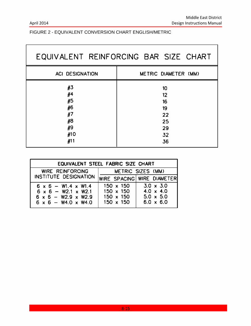
Middle East District April 2014 Design Instructions Manual
FIGURE 2 - EQUIVALENT CONVERSION CHART ENGLISH/METRIC
8-15

Middle East District April 2014 Design Instructions Manual
CHAPTER 9
FIRE PROTECTION AND LIFE SAFETY
CHAPTER 9 FIRE PROTECTION AND LIFE SAFETY ........................................................... 9-1 9.1 GENERAL ......................................................................................................................... 9-2
9.1.1 Purpose ...................................................................................................................... 9-2 9.1.2 Basis of Design ........................................................................................................... 9-2 9.1.3 Services of Fire Protection and Life Safety Specialists ............................................... 9-2
9.2 DESIGN REVIEW SUBMITTALS ...................................................................................... 9-3 9.3 FIRE EXTINGUISHING SYSTEM DESIGN ....................................................................... 9-4
9.3.1 ARCHITECT/ENGINEER (A-E) Designed Systems .................................................... 9-4 9.3.2 Contractor Designed Systems .................................................................................... 9-5 9.3.3 Non-water-based Fire Extinguishing Systems............................................................. 9-6 9.3.4 Portable Fire Extinguishers ......................................................................................... 9-6
9.4 CONCEPT REVIEW SUBMITTAL REQUIREMENTS ....................................................... 9-6 9.4.1 Concept Design Analysis ............................................................................................ 9-6 9.4.2 Concept Design Drawings .......................................................................................... 9-7 9.4.3 Certification of Review ................................................................................................ 9-8
9.5 PRELIMINARY REVIEW SUBMITTAL REQUIREMENTS ................................................. 9-8 9.5.1 Preliminary Design Analysis ....................................................................................... 9-8 9.5.2 Preliminary Design Drawings ...................................................................................... 9-9
9.6 FINAL REVIEW SUBMITTAL REQUIREMENTS............................................................... 9-9 9.6.1 The Final Fire Protection and Life Safety Design Analysis .......................................... 9-9 9.6.2 Certification of Review ................................................................................................ 9-9
9.7 READY TO ADVERTISE (RTA) DESIGN REQUIREMENTS ............................................ 9-9 9.7.1 RTA Fire Protection and Life Safety Design Submittal ................................................ 9-9
9-1
Middle East District April 2014 Design Instructions Manual
CHAPTER 9
FIRE PROTECTION AND LIFE SAFETY
9.1 GENERAL.
9.1.1 Purpose. This chapter prescribes design requirements necessary to assure adequate protection of personnel and facilities from fire.
9.1.2 Basis of Design. Design requirements shall be based upon applicable criteria contained in Unified Facilities Criteria; Fire Protection for Facilities Engineering, Design and Construction (UFC 3-600-01), as supported by specific reference to the most current edition of National Fire Protection Association (NFPA) Standards, and the International Building Code (IBC).
a. Compliance with the above criteria is mandatory. Where a conflict exists, UFC 3-600-01 shall govern. Seismic zone and provisions for seismic design shall be identified and included in accordance with NFPA standards. Unusual situations not specifically addressed by the above criteria shall be referred, in writing, to the Middle East District (MED) for resolution and direction.
9.1.3 Services of Fire Protection and Life Safety Specialists.
a. Unless the project scope of work specifically states to the contrary, all projects shall require the services of a specialist qualified and experienced in designing and specifying installed fire protection systems. In addition, the specialist shall perform an in-depth analysis of the overall facility configuration to verify that the design complies with all applicable provisions of the Life Safety Code (NFPA 101), as well as other applicable NFPA standards and the IBC. The final Design Analysis shall include certification signed by the specialist stating that the design complies with all applicable codes.
b. Qualifications of the Fire Protection/Life Safety Specialist shall be as follows:
(1) Nationally recognized fire protection engineering consulting firm, or:
(2) Member of the Society of Fire Protection Engineers, or:
(3) Graduate fire protection engineer with at least five years of full time experience in the design of various types of fire protection and life safety systems, or:
(4) Engineer whose job title is "fire protection engineer" and who has a fire protection background which includes at least five years of full time experience in the design of various types of fire protection and life safety systems.
9-2
Middle East District April 2014 Design Instructions Manual
c. Qualifications of proposed fire protection and life safety specialists shall be submitted to and approved by the Corps of Engineers project manager prior to start of design work. Failure to submit qualifications for approval prior to start of work shall not relieve the A-E of responsibility to comply with this requirement, and the design shall not proceed until this requirement is fulfilled.
d. Life safety elements include design of egress and exiting, smoke control, fire resistance ratings and related systems, in addition to extinguishing systems and fire alarm systems.
9.2 DESIGN REVIEW SUBMITTALS.
Fire Protection and Life Safety review submittals for each facility shall be provided as a separate discipline and shall include the following:
a. Analysis of UFC 3-600-01 requirements for the facilities under design as supported by the IBC and NFPA standards. Narrative shall identify occupancy group(s), allowable floor areas, construction types, interior finish ratings, fire protection systems, and other pertinent factors related to the facility being designed.
b. Complete narrative identifying criteria and rationale referencing the sections of UFC 3-600-01 used to determine fire protection features and systems to be provided.
c. Life Safety Plans of each floor of each building showing various occupancy classifications, occupant loads, units of exit capacity required vs. provided, exit routes, travel distances and other details to demonstrate compliance with The applicable provisions of the Life Safety Code (NFPA 101). Identification of construction requiring fire resistance ratings of 1-hour and greater. Identification of the locations of all openings in fire-rated construction requiring protection, and the level of protection required. Note: Unless otherwise directed, separate life safety plans will be included in the design analysis (only), not with the contract drawing package.
d. Drawings indicating pertinent details of all installed fire protection systems. Unless otherwise directed, separate "FP" drawings will be provided unless not warranted due to limited size or simplicity of the facility.
e. Calculations of all water-based fire extinguishing system designs including fire pumps, sprinkler systems, standpipes, etc. Calculations of automatic sprinkler systems shall be computer generated and shall follow methods and procedures outlined in NFPA 13. Water supplies shall be verified by water distribution system (fire hydrant or other equivalent) flow tests. These tests should be performed prior to Concept Design, but not later than Preliminary Design. Hydrant flow tests shall be conducted and test reports prepared in accordance with NFPA 291.
9-3

Middle East District April 2014 Design Instructions Manual
(Refer to para.9.3).
f. Complete description of any existing or proposed water distribution system supplying all water-based fire protection systems, including sprinkler systems and hose streams. Include calculations and flow test data from the source (elevated storage, pump station, etc.) to the system(s) under design.
g. Catalog cuts of pertinent fire protection equipment, e.g. fire pumps, foam proportioning equipment, monitor nozzles, deluge and other special water control valves, fire hose and nozzles, hose storage devices, sprinklers, cooking equipment fire extinguishing systems, etc.
h. Schematics and isometric piping diagrams clearly identifying intended configuration and operation of all fire protection system components. This is particularly applicable to more complex fire extinguishing systems such as hangar foam systems, clean agent fire suppression systems, multiple fire pump installations, etc.
i. Coordination of fire protection system components being specified under "Fire Protection" sections of the specifications and drawings with those provided under "Electrical" sections. For example, heat detectors provided to actuate a system are considered to be an integral part of the sprinkler system. Such detectors shall be shown on the "FP" drawings and described under the specification sections pertaining to the particular fire extinguishing system or systems involved. Appropriate control panel schematics and riser diagrams shall be shown on the "FP" drawings, not "Electrical" drawings.
j. Description of fire detection and alarm systems other than systems functioning as an integral part of fire suppression systems. For example, smoke detectors provided in air handling units shall be included as part of the building fire alarm system. The requirements driving the installation of such systems shall be described under the "Fire Protection" section of the design analysis, but the system shall be shown on "Electrical/Mechanical" drawings and specified under "Electrical" specifications. The design analysis shall specifically indicate rationale for selecting types of fire detectors proposed for use.
k. Fire alarm riser diagrams shall be included with "Electrical" drawings and shall clearly indicate the zoning of all initiating devices. Generally, a separate zone shall be provided for each major building area or floor, suppression system, air handling unit (ductmounted smoke detectors), etc., as appropriate for the size and complexity of each facility to assure prompt identification of alarm source.
9.3 FIRE EXTINGUISHING SYSTEM DESIGN.
9.3.1 ARCHITECT/ENGINEER (A-E) Designed Systems: Unless otherwise stated in the project scope of work, water-based fire extinguishing systems shall be hydraulically designed by
9-4
Middle East District April 2014 Design Instructions Manual
the A-E and shall include the following:
a. Location and type(s) of all sprinklers and/or nozzles.
b. Routing and sizing of all sprinkler piping.
c. Details of sprinkler risers, fire hose stations, test connections, drains, etc.
d. Hydraulic calculations complying with NFPA 13. Computer generated calculations are required. Calculation data files shall be compatible with the latest version of "HASS" fire protection software produced by HRS Systems, Inc., Atlanta, GA. Printed reports shall be similar in format to that of "HASS". Submittals shall include a CD or DVD containing all applicable data files. This shall be in addition to required hardcopy. Calculations shall use metric units, unless otherwise indicated.
e. Gridded systems shall be considered for use and employed where appropriate for high demand systems where the use of such piping configuration will result in a more efficient piping system. For example, gridded systems are usually appropriate for warehouses with high-piled storage.
f. Demand and supply curves depicting sprinkler demand requirements and water supply available as verified by actual flow testing on existing systems or calculations carried to the source of storage and pressure for newly designed systems. Appropriate hose stream allowances shall also be indicated.
g. Deviations from the above requirements will be authorized on an exception basis for relatively small or simple designs. In such cases, the A-E shall stipulate design criteria to be followed and prepare a "performance specification" requiring the contractor to design and calculate systems. (Refer to par. 9.3.2)
9.3.2 Contractor Designed Systems: Where specifically stated in the A-E’s scope of work, fire extinguishing system design will be accomplished on a "performance specification" basis whereby sprinkler locations, piping plans, pipe sizing, as well as system calculations, will be the responsibility of the contractor. In such cases, the A-E shall provide the following:
a. Occupancy classification and applicable criteria upon which sprinkler performance requirements shall be based. (Note: Requirements of UFC 3-600-01 are generally more stringent than NFPA 13).
b. Sprinkler discharge requirements in terms of density in lpm/m2 (gpm/ft
2) and
corresponding area of application in m2 (ft
2) for each occupancy classification.
c. Maximum allowable sprinkler coverage in m2/sprinkler (ft
2/sprinkler).
9-5

Middle East District April 2014 Design Instructions Manual
d. Sprinkler riser size and water supply in terms of pressure, flow and residual pressure available at the base of the sprinkler riser (identified as being required to be verified by the Contractor as in para. 9.3.1-f).
e. Sprinkler riser details and other details related to the sprinkler installation.
9.3.3 Non-water-based Fire Extinguishing Systems: When gaseous, wet or dry chemical and other special extinguishing systems are provided, the design analysis shall identify protected areas, indicate the locations and quantities of extinguishing agents, and operating circumstances for each system. In lieu of complete A-E design, such systems shall be "contractor designed" by using a "performance specification" similar to that described above for water-based fire protection systems. Pre-engineered equipment and systems shall not be considered nor provided.
9.3.4 Portable Fire Extinguishers: Portable Fire Extinguishers shall be provided in all facilities in accordance with NFPA 10. Extinguishers will generally be multi-purpose dry chemical type with a minimum rating of 2A:10B:C.
9.4 CONCEPT REVIEW SUBMITTAL REQUIREMENTS.
9.4.1 Concept Design Analysis: The Concept Fire Protection and Life Safety design analysis employing criteria set forth in paragraph 9.1.2, "Basis of Design", shall include, but not necessarily be limited to the following:
a. Specific code references or required design features.
b. List of pertinent standards and codes with dates of issue of each.
c. Classification of each building per UFC 3-600-01, IBC and applicable NFPA standards as to:
(1) Occupancy group(s).
(2) Type(s) of construction.
(3) Building height and floor area(s).
(4) Location of the building relative to
adjacent structures, yards and streets.
(5) Site water supply, hydrant configuration
and vehicle access.
(6) Presence of sprinklers or other fire
9-6

Middle East District April 2014 Design Instructions Manual
extinguishing system(s).
d. Required fire protection and life safety features such as protection of vertical openings, interior finishes, signaling systems, extinguishing systems, smoke partitions, fire doors and building service equipment.
e. Required fire resistance of the various construction assemblies including walls, doors, floors, roof and structural frame, etc.
f. Requirements relative to materials of construction to be used as interior finishes, including thermal and acoustical insulation.
g. Presence of hazardous areas requiring special protection.
h. Analysis of means of egress including verification by exit calculations.
i. Areas to be provided with automatic sprinkler systems, or other extinguishing systems and equipment, including identification of type of system, i.e. wet-pipe, dry-pipe, deluge, or preaction, for each protected area and the basic design criteria.
j. Specifics of the existing or proposed water system that will provide water for fire protection. Include water source, and sizes of storage tanks, pumps, and distribution system (verified as required by para. 9.2).
k. Description of any fire detection and alarm system.
l. Description of any smoke control system to be provided.
m. Requirements for means of egress/exit illumination, emergency power, etc..
9.4.2 Concept Design Drawings. The concept Fire Protection and Life Safety design drawings employing the criteria set forth in paragraph 9.1.2, Basis of Design, shall include, but not necessarily be limited to floor plans indicating the following:
a. The location and rating of any fire-resistive construction such as occupancy separations, area separations, shaft and stair enclosures, corridors, exit passageways, separation of hazardous areas, etc.
b. Life safety plans of each floor of each building identifying occupancy classifications, occupant loads, probable exit routes, required exit capacity vs. exit capacity provided, travel distances from each area of each floor, and other details as required to demonstrate compliance with all provisions of NFPA 101.
c. Identification of all areas to be sprinklered including occupancy hazard classifications per UFC 3-600-01 and NFPA 13.
9-7
Middle East District April 2014 Design Instructions Manual
d. Identification of all areas to be provided with other types of installed fire extinguishing systems including gaseous, dry or wet chemical, etc.
e. Location and classification of standpipes and hose systems, and portable fire extinguishers.
f. Identification of smoke compartments associated with smoke control systems.
g. Characteristics of the water supply for fire protection.
9.4.2.1 Other drawings shall be provided as necessary to clearly define and explain all fire protection and life safety features and requirements.
9.4.3 Certification of Review. Written certification that the Concept Fire Protection and Life Safety design has been reviewed by the approved fire protection and life safety specialist and that the design complies with all applicable codes and criteria shall accompany the Concept Review Submittal.
9.5 PRELIMINARY REVIEW SUBMITTAL REQUIREMENTS.
9.5.1 Preliminary Design Analysis. The Preliminary Fire Protection and Life Safety design analysis shall include all items in the Concept design analysis incorporating all necessary revisions. In addition, the following specific items shall also be included:
a. Complete basis of design and calculations for determination of occupant load by floor area and fire area, number of exits, required egress capacities, maximum allowable travel distances, and other features required for compliance with the Life Safety Code, NFPA 101.
b. Complete basis of design for fire extinguishing systems and equipment to be provided. Include data as specified in paragraph 9.3 (Fire Extinguishing System Design).
c. Water system analysis including calculations, existing water supply test results and water supply and demand curves to demonstrate capability of water system to satisfy fire protection requirements of UFC 3-600-01 and other applicable criteria.
d. Calculations to determine other fire extinguishing system requirements, e.g. capacity of foam concentrate storage tanks, quantities of CO2, size of air compressors for dry-pipe sprinkler systems, fire pumps, and similar requirements.
e. Fire alarm/detection system configuration.
f. Types and ratings of portable fire extinguishers to be provided.
9-8
Middle East District April 2014 Design Instructions Manual
9.5.2 Preliminary Design Drawings. The Preliminary Fire Protection and Life Safety design drawings shall consist of all design features of the Concept design incorporating all necessary revisions. In addition, the following specifications shall also be included:
a. All fire protection system design requirements specified under paragraph 9.3 "Fire Extinguishing System Design".
b. Complete basis of design and operating sequences for all fixed fire extinguishing systems.
c. Layouts of all fixed fire extinguishing systems including locations and mounting details of agent storage containers, control panels, test connections, hose cabinets, etc.
d. Locations of all fire doors, fire/smoke dampers, fire alarm system devices, and similar equipment related to the overall fire protection scheme of each facility.
e. Location, type, rating and mounting details of portable fire extinguishers to be provided.
f. Schematics, isometrics and other details as necessary to clearly delineate the arrangement and operation of all fire extinguishing systems.
9.6 FINAL REVIEW SUBMITTAL REQUIREMENTS.
9.6.1 The Final Fire Protection and Life Safety Design Analysis shall include all the items in the Preliminary design analysis, incorporating all necessary revisions as well as completed calculations on fire extinguishing system(s). The Final Fire Protection and Life Safety design drawings shall be expanded to include all revisions and refinements necessary to complete the design. The design analysis and drawings submitted for Final review shall be complete, as described in Chapter 1, GENERAL INSTRUCTIONS.
9.6.2 Certification of Review. Written certification that the Final Fire Protection and Life Safety Design is complete and has been reviewed by the approved fire protection and life safety specialist and that the design complies with all applicable codes and criteria.
9.7 READY TO ADVERTISE (RTA) DESIGN REQUIREMENTS.
9.7.1 RTA Fire Protection and Life Safety Design Submittal shall reflect incorporation of the comments generated during the Final design review and previous reviews. The design shall be complete forming an integral part of the construction package.
9-9

Middle East District April 2014 Design Instructions Manual
CHAPTER 10
CHAPTER 11 HEATING, VENTILATING, AND AIR CONDITIONING
CHAPTER 10 HEATING, VENTILATING, AND AIR CONDITIONING ................................... 11-1 10.1 GENERAL ..................................................................................................................... 11-2 10.2 APPLICABLE PUBLICATIONS ..................................................................................... 11-2 10.3 CONCEPT SUBMITTAL REQUIREMENTS .................................................................. 11-4
10.3.1 General Considerations. ......................................................................................... 11-4 10.3.2 Concept Design Analysis ........................................................................................ 11-4 10.3.3 Concept Design Drawings ...................................................................................... 11-6
10.4 PRELIMINARY REVIEW SUBMITTAL REQUIREMENTS. ............................................ 11-8 10.4.1 Preliminary Design Analysis ................................................................................... 11-8 10.4.2 Preliminary Design Drawings .................................................................................. 11-8
10.5 FINAL REVIEW SUBMITTAL REQUIREMENTS ........................................................... 11-9 10.5.1 Design Analysis ...................................................................................................... 11-9 10.5.2 Drawings .............................................................................................................. 11-11 10.5.3 Catalog Cuts ......................................................................................................... 11-12
10.6 READY TO ADVERTISE (RTA) DESIGN REQUIREMENTS ...................................... 11-12 10.7 TECHNICAL REQUIREMENTS .................................................................................. 11-12
10.7.1 General Considerations ........................................................................................ 11-12 10.7.2 Ventilation ............................................................................................................. 11-15 10.7.3 Air Conditioning .................................................................................................... 11-17 10.7.4 Site Utilities ........................................................................................................... 11-31 10.7.5 Equipment and Design Data Schedules ................................................................ 11-32
AIR-CONDITIONING DESIGN SCHEDULE ............................................................ 11-33 AIR HANDLING UNIT SCHEDULE ......................................................................... 11-34 COOLING COIL SCHEDULE .................................................................................. 11-35 HEATING COIL SCHEDULE ................................................................................... 11-36 INERTIAL SEPARATOR SCHEDULE ..................................................................... 11-36 FAN SCHEDULE ..................................................................................................... 11-37 EXHAUST HOOD SCHEDULE ............................................................................... 11-38 PUMP SCHEDULE.................................................................................................. 11-38 WATER CHILLER SCHEDULE ............................................................................... 11-39 VARIABLE (CONSTANT) VOLUME (REHEAT) BOX SCHEDULE .......................... 11-40 ACOUSTICAL SOUND TRAP SCHEDULE ............................................................. 11-40 FILTER SCHEDULE ................................................................................................ 11-41 FLOW CONTROL VALVE SCHEDULE ................................................................... 11-41 TEMPERATURE CONTROL VALVE SCHEDULE................................................... 11-42 COOLING TOWER SCHEDULE ............................................................................. 11-42
11-1

Middle East District April 2014 Design Instructions Manual
CHAPTER 10
HEATING, VENTILATING, AND AIR-CONDITIONING
10.1 GENERAL.
The major requirements for the design of space heating systems, central heating and
air-conditioning plants, central chilled water distribution systems, ventilating systems, central air
conditioning systems, and, unitary air-conditioning systems for permanent construction are
discussed in this section. For specific projects, supplemental guidance may be provided. These
additional requirements will also be incorporated in the design effort. Engineering practices
recommended in ASHRAE Handbooks shall be followed in regard to special conditions and
problems not specifically covered herein. Specific submittal requirements in this chapter
supplement the requirements of Chapter 1: GENERAL INSTRUCTIONS. All required
documents, including drawings and design analysis, shall be prepared in accordance with
Chapter 2: PRESENTATION OF DATA.
10.2 APPLICABLE PUBLICATIONS.
The current edition of the publications listed below form a part of this Manual.
Headquarters, U.S. Army Corps of Engineers (HQUSACE) Publication.
Architectural and Design Criteria. Engineering Instructions (AEI).
Department of the Army Technical Manuals (TM):
TM 5-785. Engineering Weather Data.
TM 5-805-4. Noise and Vibration Control.
TM 5-809-10. Seismic Design for Buildings.
TM 5-810-1. Mechanical Design Heating, Ventilating, and Air Conditioning.
TM 5-815-3. Heating, Ventilating and Air Conditioning (HVAC) Control
Systems. Department of Defense (DOD),Military Handbook:
MIL-HDBK-1191. Medical Military Construction Program Facilities, Design and
11-2

Middle East District April 2014 Design Instructions Manual
Construction Criteria.
American National Standards Institute, Inc. (ANSI) Standards:
A 13.1. Scheme for the Identification of Piping Systems.
B31.1 Power Piping. & B31.1a & B31.1b
American Society of Heating, Refrigeration, and Air-Conditioning Engineers (ASHRAE)
Inc. Standards:
ASHRAE Handbooks, Latest Editions.
American Society of Mechanical Engineers (ASME) Codes:
Boiler and Pressure Vessel Codes: Section I. Rules for Construction of Power
Boilers. Section IV. Rules for Construction of Heating Boilers. Section VIII-D.
Rules for Construction of Pressure Vessels.
National Institute of Occupational Safety and Health (NIOSH):
NIOSH 76-130. Lead Exposure and Design Consider rations for Indoor Firing
Ranges.
National Fire Protection Association (NFPA) Publications:
No. 31. Standards for Installation of Oil Burning Equipment.
No. 54. National Fuel Gas Code.
No. 70. National Electric Code.
No. 90A. Standards for Installation of AirConditioning and Ventilating Systems.
No. 91. Blower and Exhaust Systems for Air Conveying of Materials.
Sheet Metal and Air-Conditioning Contractors National Association, Inc
(SMACNA):
HVAC Duct Construction Standards - Metal and Flexible.
11-3
Middle East District April 2014 Design Instructions Manual
American Conference of Government Industrial Hygienists:
Industrial Ventilation, A Manual of Recommended Practice.
10.3 CONCEPT SUBMITTAL REQUIREMENTS.
10.3.1 General Considerations. a. At the Concept design stage of project development it is recognized that all
calculations are tentative for analysis purposes and only indicate approximate
capacities of equipment. Any dimensions and sizes required are order-of-
magnitude figures, conservatively stated, to assure adequate space for
installation and maintenance of equipment and utility elements such as piping,
ductwork, etc., in congested areas.
b. Equipment shown in plans and sections is not shown in great detail but is
shown merely as simple geometric forms with approximate correct dimensions.
c. Piping layouts shown are simple main pipe runs showing general location,
routing and, when applicable, approximate order-of-magnitude sizes. Control
valves, check valves, etc., are shown only as required to indicate function of the
system. Only routing of pipe mains feeding batteries of water coils are shown, not
individual lines to coils unless required for clarity of the system.
d. System flow diagrams, layouts, and one of each type of take-off, branch, or
feed must be shown but not all individual branches. Purpose of the flow diagram
is only to show system design intent and the basic principle of system operation.
e. Drawings and sketches. Scale of concept drawings will generally be smaller
than the working drawings. Plans and sections need be only large enough to
properly show pertinent information. Sketches will be acceptable when sufficient
to show pertinent information or convey basic system concepts. Quantity of
concept drawings are to be kept to the minimum number required to convey
basic systems information. Some mechanical information required in the Concept
submission may logically be included on other discipline drawings or in sketch
form in the design analyses and need not be indicated on formal drawings.
10.3.2 Concept Design Analysis. The following specific items shall be included, as
11-4

Middle East District April 2014 Design Instructions Manual
applicable.
10.3.2.1 Heating, Ventilating and Air-Conditioning (HVAC).
a. For air-conditioning, give a statement citing applicable specific references
(DOD, TM's Programming Data, etc.) used to the extent air-conditioning is
authorized and to any authority for waiver of these criteria. State whether for
comfort cooling or according to technical requirements or both. For technical
requirements, show the authorized tolerance for temperature and humidity
control, the degree of air cleaning or purity required, and any other special
considerations involved.
b. For evaporative cooling, cite applicable references as to the extent authorized
and to any authorized waiver of these criteria. Note if single or two-stage
process.
c. For cold storage facilities, indicate room holding temperatures, commodities to
be held in cold storage and the quantity of commodity to be stored. (May be
indicated on drawings.)
d. State the indoor and outdoor design temperatures for heating and cooling and
proposed "U" factors for walls, ceilings, floors, etc.
e. Prepare tentative heating and cooling block load calculations for heating and
cooling systems.
f. Prepare tentative ventilation calculations for ventilated areas.
g. For air distribution, prepare tentative calculations for each typical zone of
control, fan type and unit sections required.
h. Prepare overall tentative air balance calculations with a flow diagram showing
quantities of air handled and circulated throughout each building as a whole
including quantities for outside and exhaust air.
i. Describe the proposed heating ventilation and air-conditioning systems and
their associated air distribution systems and provide rationale used for selection
of the recommended systems.
11-5

Middle East District April 2014 Design Instructions Manual
j. Describe ventilating systems. Provide statements whether gravity or
mechanical systems are proposed. If mechanical systems, indicate whether
supply or exhaust. State requirements for outside air and the basis for
determination of quantity, i.e., number of air changes per hour, of CFM per
person, or other.
k. Describe the control system for each major typical air distribution system.
Control system descriptions may be provided on plans or as part of the narrative.
10.3.2.2 Central Chilled Water Systems.
a. Describe the proposed type of chilled water plant and justification for selection,
operating pressure and temperature, and approximate capacities. Describe the
type of chilled water distribution system outside buildings, pumping schemes and
capacities, routing and type of system, and whether aboveground, tunnel or
underground piping will be used. Include soil investigations and survey, and
materials evaluation with recommendations for selection of piping materials.
b. Develop a failure mode analysis of each chilled water plant and distribution
system to minimize service interruptions, equipment damage, and hazards to
personnel. Failure mode analysis will be limited to those conditions that may
result in a hydraulic pressure wave propagation. Loss of electrical power, control
signals, and equipment failures, as well as human error or lack of skill, shall be
included in the analysis. Maximum use of computer methods shall be made
during the analysis. Input and output data, as well as a user-oriented description
of the programs involved shall be provided as part of the documentation. The
analysis shall follow the normal design sequence and shall be updated as the
system design effort continues and additional information becomes available.
10.3.3 Concept Design Drawings. The following specific items shall be shown on the
HVAC Concept design drawings when applicable.
10.3.3.1 Tentative schematic flow diagrams along with system descriptions of all
systems considered, including air distribution, chilled water distribution and pumping. The
rationale for systems recommended shall be clearly documented.
a. Tentative control description of operation to clearly indicate general features
11-6
Middle East District April 2014 Design Instructions Manual
sufficient to define method of control of each typical major equipment and
system. (May be shown in design analysis.)
10.3.3.2 All systems Recommended for Inclusion. The following applies to all systems
recommended for inclusion in a project.
a. Flow diagrams of all systems proposed. These diagrams shall be an accurate
schematic representation of each system showing proposed equipment, primary
control valves, dampers and control loops, as applicable.
b. Provide single line layouts of heating and air conditioning systems showing
equipment and contemplated zoning for each building. Drawings shall identify
rooms and be sufficiently complete to show the location, arrangement, and
approximate capacities of all major items of equipment and space allocated for
servicing and maintenance. The following items shall be included as a minimum.
(1) Single line layouts of typical HVAC systems with approximate
representative duct sizes of main runs and air quantities. This includes
exhaust systems and make-up air systems.
(2) Layout of major mechanical equipment, to determine space
requirements, and adequacy of mechanical room sizes.
(3) Component parts of air handling equipment should be indicated, i.e.,
fan, coils, filters, etc.
(4) Show required maintenance space for all major equipment, preferably
with dotted lines and backed up by xerox copies of typical manufacturers'
cataloged maintenance space in design analysis. A minimum 30-inch
clearance around equipment shall be shown to allow "squatting" for the
maintenance purposes.
(5) Show major piping single line with approximate size.
(6) Indicate approximate capacities of all major equipment including
horsepower of motors and kw of major electric heating elements, CFM of
major air handlers, etc.
11-7
Middle East District April 2014 Design Instructions Manual
c. Show the approximate routing of site chilled water piping, size and location of
valve boxes, drain and vent points. Include a piping and valve layout for each
typical valve box, air vent and drain point.
10.4 PRELIMINARY REVIEW SUBMITTAL REQUIREMENTS.
10.4.1 Preliminary Design Analysis. The Preliminary design analysis shall include all
items in the Concept design analysis and any necessary revisions. In addition, the following
specific items shall be included when applicable.
a. Detailed calculations for sizing equipment, piping, ductwork, control valves,
etc.
b. Schematics for the control schemes used.
c. Any other information or computations required to permit verification that the
design complies with the design criteria, codes, and standards and is satisfactory
for the intended purpose.
10.4.2 Preliminary Design Drawings. The following specific items shall be
shown when applicable.
10.4.2.1 Flow Diagrams of All Systems. These diagrams shall show all the information
given on the Concept drawings but in greater detail. The diagrams shall include equipment, all
ductwork and piping including sizes and flow rates, all dampers, valves, and miscellaneous
accessories for the duct and piping systems, and the instrumentation and control devices for the
systems.
10.4.2.2 Plans showing layout and details of the final version of all HVAC systems. The
location, arrangement, capacity, and space requirements of all equipment shall be indicated.
Selected zones of air distribution shall be sufficiently completed to indicate the solution of the
design for the remainder of the system and the precautions taken to coordinate the design with
the architectural, structural and electrical phases of construction. Equipment room and chilled
water plant layouts shall be sufficiently complete to show piping and duct layouts and access for
maintenance. Since equipment rooms represent the most congested areas for both equipment
and piping, the following guidelines should be followed when drawings are being prepared.
11-8
Middle East District April 2014 Design Instructions Manual
a. Single line ducting layouts are not sufficient to adequately plan major
installations and check interferences.
b. All piping shall be shown by single line layouts and symbols. However the
designer shall assure that the space allotted for installation of the piping,
including insulation, valves, fittings and accessories, is adequate.
c. All ductwork and fittings in equipment rooms and other congested areas, shall
be drawn to scale by double line layouts.
d. All equipment shall be outlined to scale, and maintenance or removal space
shall be indicated by dotted lines.
e. Removal, replacement, or moving space must be considered for the largest
and heaviest equipment when a drawing is made.
f. In plans, sections, and details, these same rules should apply.
g. Vertical control for horizontal runs of piping, ductwork, etc. shall be clearly
delineated on the drawings. The drawings, by sections, elevations, or notes, shall
show vertical control of piping and ductwork. The design shall ensure sufficient
vertical clear height has been provided. This includes site chilled water piping.
10.4.2.3 Equipment Schedules. The final form of all equipment schedules which will be
included in the project shall be shown with Preliminary equipment data filled in.
10.4.2.4 Catalog Cuts. Catalog cuts shall be submitted for all major items of equipment.
Catalog cuts shall be a part of the design analysis.
10.5 FINAL REVIEW SUBMITTAL REQUIREMENTS.
10.5.1 Design Analysis. The design analysis shall include all of the information
required in the Preliminary submittal but in its final form, also any additional information
required, and the information listed below when applicable.
a. All textbooks, handbooks, and other references used in the design analysis
11-9
Middle East District April 2014 Design Instructions Manual
shall be cited, giving page and/or paragraph numbers from which data are
obtained.
b. Heat transmission calculations shall be shown for all heat transmission
coefficients not directly obtained from a standard reference book.
c. Cooling load and heat gain calculations shall, in general, conform to the
procedure given in the latest issue of the ASHRAE Handbooks. All corrections
and assumptions, such as time of day, outdoor daily temperature range, wall
color, building orientation, latitude, etc., shall be stated. Where computerized
calculations are submitted, a complete description of the method and formulas
used, column headings and data output or results, and index to the computer
printout shall be furnished.
d. The basis for determining the quantity of all ventilation air shall be indicated.
e. A psychometric chart, including a plot for all processes, shall be included in the
analysis.
f. The determination of air distribution shall be made to include the total air cfm
and the individual room cfm.
g. Water pump gpm, TDH, and horsepower calculations shall be shown for
condenser and chilled water circuits. The friction losses in the water circuits and
pipe sizing shall be tabulated.
h. The method of sizing cooling towers shall be shown.
i. The humidification or dehumidification requirements shall be stated.
j. Equipment sizing calculations to support the selection of all equipment shall be
shown in the design analysis.
k. Major items of gas equipment shall be selected from manufacturers' catalogs
and the model numbers shall be stated in the analysis. This information will not
appear on the drawings.
l. Schematic diagrams shall be shown and a control sequence of operation for
11-10

Middle East District April 2014 Design Instructions Manual
each typical system shall be described with all control points and settings
defined.
m. The method for achieving air balance in systems for supply air, return air,
outside air, exhaust air, and exfiltration shall be described.
n. The method for maintaining positive pressure relative to outside air to prevent
the entrance of windblown dust shall be described.
o. Explanatory notes shall be included in the design analysis covering all
rationale for design which would not be obvious to an engineer reviewing the
analysis. Methods of air-conditioning and controls for air-conditioning systems
shall generally be confined to those in common use in the industry. The A-E shall
review the prepared plans and specifications and determine that they are in
accordance with the Manual and all other criteria and instructions furnished by
the CE. It will be the responsibility of the A-E to coordinate the HVAC systems
with the other trades involved in the building design and to eliminate interference
between HVAC equipment and other components of the building.
p. The design analysis shall show calculations for all items listed under
paragraph: Equipment and Design Data Schedules. (10.7.5)
10.5.2 Drawings. Flow diagrams and plans containing all the necessary details to attract
accurate and competitive bids and to afford a clear understanding throughout construction shall
be included in the drawings. Plans shall be complete in all respects, showing location of all
equipment, ductwork, piping, and accessories. Sections and details shall be provided as
required to clearly show all aspects of the system design. The following specific items shall be
included when applicable.
a. Schematic flow or riser diagrams of all systems. Information shall be as
required on preliminary submittal, but in greater detail.
b. Equipment room layouts and appropriate sections and details.
c. Duct and pipe sizes.
d. Vertical control for horizontal runs of piping, ductwork, etc. shall be clearly
11-11

Middle East District April 2014 Design Instructions Manual
delineated on the drawings. The drawings, by sections, elevations, or notes, shall
show vertical control of piping and ductwork. The design shall ensure sufficient
clear vertical height has been provided.
e. Registers, diffusers, grilles, dampers, turning vanes, transitions, flexible
connections, valves, etc. shall be shown and identified.
f. Controls schematic diagrams and control sequences of operation for all
systems.
g. Equipment to be furnished and/or installed by others.
h. Equipment schedules giving capacities, working temperatures and pressures,
and other pertinent data necessary to give a clear and concise description of all
equipment.
10.5.3 Catalog Cuts. Complete catalog cuts and data sheets shall be submitted for all
major items of equipment. Catalog cuts shall be a part of the design analysis.
10.6 READY TO ADVERTISE (RTA) DESIGN REQUIREMENTS.
The comments generated during the Final design review shall be incorporated in the
documents before they are submitted as Ready to Advertise.
10.7 TECHNICAL REQUIREMENTS.
10.7.1 General Considerations.
10.7.1.1 Packaged Equipment. Standard manufactured packaged type equipment shall
be used to the greatest extent possible to simplify specifying, purchasing, installation, spare
parts procurement and maintenance of equipment.
10.7.1.2 Soil Surveys shall be conducted to determine the electrical resistivity and
percolation characteristics of the soil and to acquire ground water information along the
alignment of all proposed buried piping systems.
10.7.1.3 Seismic Design for the mechanical systems shall conform to the requirements
of TM 5-809-10. Seismic zone determinations shall be in accordance with Chapter 8,
11-12
Middle East District April 2014 Design Instructions Manual
STRUCTURAL.
10.7.1.4 Dust Control. In addition to providing air filtration, which is described
hereinafter, conditioned spaces must be maintained at a positive pressure relative to the outside
air in order to prevent windblown sand and dust from entering. Backdraft dampers or louvers
should be used on all mechanical system openings to the exterior.
10.7.1.5 Noise Control. All noise control design work shall be in accordance with TM-
805-4. The sound levels for various applications for both centrifugal and propeller type fans
shall be as set forth in the ASHRAE Handbooks. Specialized areas such as conference
rooms, theaters, etc. shall be evaluated to ensure that proper acoustic treatment has been
provided. An acoustical analysis shall be included in design analysis to support acoustical
design requirements.
10.7.1.6 Design Temperatures.
a. Indoor design temperatures shall be in accordance with AEI Design Criteria,
and as described hereinafter.
(1) Equipment Rooms: Unoccupied mechanical and electrical equipment
rooms shall be provided with mechanical ventilation or relief heating
and/or cooling as required to limit the maximum room temperature to
32oC in summer and minimum temperature to 4.5
oC in winter.
Unoccupied equipment rooms for critical switchgear or controls may be
provided with 100 percent backup air-conditioning if required by the user
or viewed as mission critical.
(2) Stationary Work Stations shall be spot cooled with mechanical
refrigeration if the facility is not centrally air conditioned and the space
temperature is determined to exceed 32oC.
(3) Control rooms shall be air-conditioned for normal comfort conditions
(25.5oC, 50% RH).
(4) Kitchens and Laundries: In geographical areas where mechanical
ventilation would result in inside temperatures higher than 35oC.,
11-13
Middle East District April 2014 Design Instructions Manual
mechanical cooling shall be provided. Either spot cooling or cooling of the
entire area to 32oC shall be used depending on the requirements of the
particular facility. Refer to paragraph: Spot Cooling. (10.7.2.11)
(5) Transformer Rooms: When transformers are located, as determined
by electrical requirements, within an enclosed space, the room shall be
air conditioned to limit the maximum room temperature to 32oC. Return air
may not be ducted to the central air conditioning systems.
b. Weather design conditions shall be in accordance with TM 5-785, ASHREA
Fundamentals Handbook or in accordance with data supplied by Middle East
District (MED). Outdoor winter design temperatures shall normally be selected
based upon the 97 1/2% dry bulb column temperature. Summer outside design
temperatures shall normally be selected based upon the 2 1/2% dry bulb and the
5% wet bulb column temperatures. Critical systems shall be selected based upon
the 1% column temperatures, as defined in AEI Design Criteria.
10.7.1.7 Smoke Detection. Smoke detection and emergency automatic controls shall be
in accordance with NFPA 90A and NFPA 72.
10.7.1.8 Fire an Smoke Dampers. Dampers shall be provided for protection of
openings in walls, partitions or floors in accordance with NFPA 90A.
10.7.1.9 Sand Screening: Where windblown sand is a problem, screening around
exterior mounted equipment shall be provided as follows:
a. "Screen" must be louvered, semi-open block (decorative), or of a design to
allow air circulation to the equipment.
b. Where solid walls are required, a minimum distance of 3 meters shall be
maintained between wall and condenser coil intakes.
c. Movable access shall be provided in "screen" for condenser coil/radiator
removal and other maintenance functions hindered by "screen".
10.7.1.10 System Segregation. Piping systems shall contain sufficient isolation valves to
allow segregation of the system for maintenance, draining, and/or testing. Piping systems,
11-14

Middle East District April 2014 Design Instructions Manual
which may be extended by another contractor or at some future date, shall be terminated with
blind-flanged valved connections.
10.7.2 Ventilation.
10.7.2.1 Hazardous Areas. The exhaust system discharge point shall be such that the
vapors cannot enter other areas through open windows or the fresh air system. The capacity of
the exhaust system shall be sufficient to prevent flammable or toxic vapors from escaping into
areas surrounding the hazardous areas. Direct recirculation shall not be permitted. Mechanical
ventilation and exhaust systems for flammable and toxic gases shall follow the codes of practice
of the National Fire Protection Association, TM 5-810-1, Industrial Ventilation Standards and the
ASHRAE Handbooks.
10.7.2.2 Special Process Spaces. Special process areas require a greater degree of
ventilation to remove dust, fumes, gases, or vapors harmful to personnel. Therefore, special
consideration shall be given to these areas, and the ventilation system shall be designed,
installed, and protected in accordance with ASHRAE Handbooks and "Industrial Ventilation
Manual".
10.7.2.3 Special Buildings. Ventilation requirements for special buildings will be
evaluated, and recommendations and calculations will be submitted for approval to the CE
prior to commencement of design.
10.7.2.4 Air Distribution System. Air distribution systems for ventilation systems
shall be as described in paragraph: Air Conditioning.
10.7.2.5 Kitchen Exhaust Hoods, Filters, and Accessories. The hoods shall be of an
approved design for a particular application. They shall be a minimum of approximately 600
mm high in order to provide a reservoir to confine sudden puffs of smoke, fumes, or steam
until they can be evacuated by the system The hood shall extend beyond the equipment
surface by 150 mm for every 600 mm of height above the equipment. The minimum
overhang for the hoods shall be approximately 300 mm. The transformation from hood face
to duct shall be gradual to avoid turbulence and inefficiency of air flow. The hood shall be
dimensioned to facilitate the use of standard size filters and to be readily accessible for
cleaning.
a. Whenever outside air is required as make-up for the exhaust air quantity in the
11-15
Middle East District April 2014 Design Instructions Manual
kitchen, the exhaust hood shall be of the air curtain type in which the hood supply
air is fed to the work area by means of slots in the hood perimeter. If possible a
packaged unit consisting of a hood, supply air fan with filters, and exhaust fan
shall be used for this application. Supply air quantity shall be approximately 80
percent of the exhaust air quantity.
b. Make-up air filtration. For make-up air filtration requirements see paragraph:
Air Filtration.
10.7.2.6 Fans. The fan bearings, belt, and pulleys shall be fully protected from the
fumes. Fan wheel and shaft shall be constructed of non-sparking material where required.
Laboratory exhaust fans shall be coated with an appropriate material to protect them from
corrosive fumes, etc.. Because of the tendency of the filters to clog, the fan shall be capable of
operating efficiently at static pressure in excess of those calculated. Non-overloading fans are
preferred so that they may be operated effectively when filters are removed or contaminated.
Discharges of grease hood ventilation systems shall be vertical.
10.7.2.7 Laboratory Fume Hoods. Hoods shall be of a manufacturer's standard
design constructed of materials suitable for the contaminants involved. Discharges of fume
hood ventilation systems shall be vertical above the building roof.
10.7.2.8 Battery Rooms and UPS Rooms. Each room where hydrogen is generated
shall be exhaust ventilated to the exterior of the building in accordance with NFPA-70. Each
room shall be air conditioned to not less than 26.5oC.
10.7.2.9 Indoor Firing Ranges shall be ventilated in accordance with NIOSH 76-
130.
10.7.2.10 Fuel Burning Appliance Combustion and Ventilation Air shall be in accordance
with the recommendations of NFPA No. 54 for Gas or NFPA No. 31 for Oil.
10.7.2.11 Spot Cooling. When spot cooling systems are employed, they shall be of
the mechanical refrigeration type designed in accordance with the latest ASHRAE
Handbooks. Evaporative cooling may be used where practical and shall be approved by
Middle East District (MED). Terminals shall be swivel type with adjustable air discharge
patterns.
11-16
Middle East District April 2014 Design Instructions Manual
10.7.3 Air Conditioning.
10.7.3.1 Equipment.
a. Water chillers/condensers.
(1) Air cooled packaged chillers shall be utilized for decentralized, small
tonnage, space cooling applications wherever possible because of their
superior record of reliability and because they require considerably less
maintenance than other water chilling systems. Only chillers rated for
condenser entering air temperatures of 12.2oC higher than the outdoor
design dry bulb temperature shall be used and chillers shall be sized on
the basis of this condenser entering air temperature. Remotely located air
cooled condensers may be used when packaged chillers are not
practical. Air-cooled condensers should not operate at less than 9.5oC
differential between refrigerant condensing temperature and entering air
in order to avoid control problems at partial load. Factory mounted, air
side type control shall be used to minimize the refrigerant charge and the
risk of slugging the compressor or diluting the lubrication oil with liquid
refrigerant. Compressors shall have time delays to start after the fan
when condenser coils are placed to sunlit locations in order to avoid
startup high pressure tripouts. Air-cooled condensers should be vertical or
horizontal coil, propeller fan type. The fan motors shall be totally enclosed
or as required to prevent the accumulation of sand in cooling passages,
and shall be designed to operate at the local airstream temperature which
may be higher than ambient if the motor is in the leaving airstream.
Airtight, dustproof control cabinets shall be sunshaded and internally
cooled without requiring the introduction of outside air. A compressed air
hose or some other means of removing sand, lint, and other foreign
materials which may have accumulated on the condenser should be
provided.
(2) Water-cooled. When specifying a water-cooled condenser for chillers,
a complete description of the cooling water treatment, automatic
blowdown control, and cooling tower construction will be included. See
11-17
Middle East District April 2014 Design Instructions Manual
paragraph: Water Treatment for water quality control limits. Water cooled
condensers for small tonnage space cooling applications shall be close
connected, closed-shell, and straight cleanable fin tube type with water in
the tubes and an extended surface on the shell side. Water tube
velocities recommended to minimize fouling and erosion should be
between .9 meters and 1.8 meters per second.
(3) Radiator cooled. In extreme conditions, where water is either unusable
or totally unavailable, the use of radiator-cooled water chillers shall be
considered. In such systems a standard water-cooled chiller with "high lift"
capability would be used. The condenser water would be pumped via a
closed circuit system through a large industrial type radiator.
(4) Due to environmental concerns regarding ozone depletion, all
mechanical refrigeration equipment shall use refrigerants with an Ozone
Deflection Potential less than or equal to 0.05. Note that R-407c, R-410,
R-123 and R-134a all meet this requirement.
b. Cooling towers.
(1) General. When field-erected towers are required on projects for
evaporative cooling purposes, the towers shall be of masonry shell
construction utilizing ceramic tile fill. Cold water basins should be deep to
enable maintenance personnel to move about under the fill to wash down
accumulated dirt, sand, and debris. Cleanout sumps shall be provided for
this purpose. When non-field erected towers (packaged or factory
fabricated) are to be used, the materials of construction shall be those
required by the project. Cooling towers shall be sized based on the 1
percent wet bulb temperature. The specifications shall require that all
towers be tested by Cooling Tower Institute (CTI) procedures, but CTI
certification shall not be required. The specifications shall also require
that the manufacturer guarantee 100 percent thermal performance of the
tower.
(2) Sand control. Means shall be provided to limit the amount of sand
blown into the tower. The most straight forward means of accomplishing
11-18
Middle East District April 2014 Design Instructions Manual
sand control is through the use of sand louvers or maze intake structures.
The location and size of the intake structure can be adjusted to fit
architectural considerations so long as basic air flow patterns are
unaltered and sufficient air flow area is provided.
(3) Side Stream Filtration. Means should be provided to maintain
concentration of total dissolved solids in the circulating water to an
acceptable level by use of side stream filtration and appropriate retention
time in the cooling tower sump.
c. Air handling units (AHU's).
(1) Modular packaged units shall be used rather than "built-up" systems to
the greatest extent possible. Compartmentalization of the air handling
equipment shall be considered in order to limit the amount of space
affected by failure of a unit. Stacking of fan rooms shall be utilized when
possible in multistory buildings.
(2) Cooling coils. The recommended cooling coil face velocity is 152
meters per minute (mpm). Maximum allowable face velocity is 183 mpm.
In general, wide fin spacing shall be used when possible, even if coil
depth needs to be increased to maintain the required capacity. The
maximum fin spacing shall be 8 fins per 25 mm. Cooling coils, greater
than 5 ton refrigeration capacity, shall have copper tubes and copper fins
for facilities located within 32 kilometers (km) of the Sea coast. For air-
conditioners (single packaged units, split systems, etc.) the total capacity
must be derated such that the minimum sensible coil capacity of the
equipment will meet the sensible load requirements.
(3) Electric heating coils. In single zone or zoned reheat installations, the
heating in ducts and AHU's shall be electric. When multi-zone
installations are required, electric hot deck coils are not recommended
because the varying air flows across the different parts of the coil will
cause thermal overload tripout. In these instances, consideration shall be
given to using additional single zone or zoned reheat units rather than a
lesser number of multi-zone units. Where it is possible to use a
11-19
Middle East District April 2014 Design Instructions Manual
manufacturer's standard electric heating coil modules in modular AHU's,
their standard product shall be used. Where the heating requirement is
too small for the electric coil to be installed in the AHU, it shall be installed
in the ductwork. The following requirements shall be met for electric coils.
A. The heater shall be completely prepackaged, including all
conductors, safety controls, etc.
B. The only external controls required shall be the temperature
sensor and controller (step switch or current valve).
C. Heating elements shall be finned tubular (enclosed element)
type, for facilities within 32 km of the sea coast.
D. Generally, heaters shall be sized to fit the duct exactly.
Where it is necessary to have duct transitions, they shall be in
accordance with the requirements of SMACNA.
d. Pumps for chilled water and condenser water shall, in general, be end suction
type for capacities up to 284 lpm and of the split case type for capacities over
284 lpm. Vertical turbine type pumps may be used for condenser water. Pumps
such as vertical in-line pumps shall be allowed where their use will significantly
simplify pump room piping. Primary pumping shall be accomplished by using
several constant speed pumps in parallel. Motors shall be of sufficient size
without operating in the service factor for the duty to be performed and will not
exceed their full rated load when the driven equipment is operating at specified
capacity under the most severe conditions likely to be encountered. See
paragraph: ELECTRIC MOTORS.
10.7.3.2 Piping, Valves and Fittings.
a. Refrigerant piping shall be designed in accordance with the ASHRAE
Handbooks. Where an optional refrigeration piping system is allowed, design of
piping for all options shall be provided. Hot gas discharge and suction lines shall
be designed to ensure oil return. Oil separators shall be provided as required.
Hot gas by-pass connections may be permitted to allow unit operation below
minimum capacity control step.
11-20
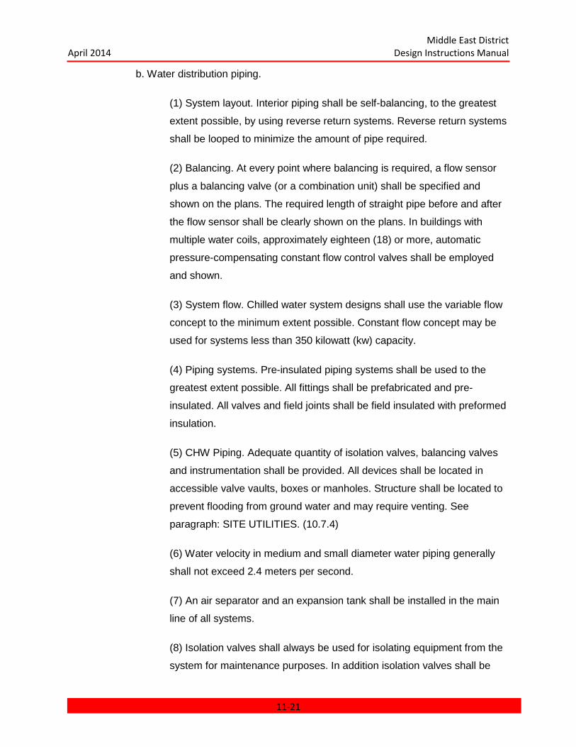
Middle East District April 2014 Design Instructions Manual
b. Water distribution piping.
(1) System layout. Interior piping shall be self-balancing, to the greatest
extent possible, by using reverse return systems. Reverse return systems
shall be looped to minimize the amount of pipe required.
(2) Balancing. At every point where balancing is required, a flow sensor
plus a balancing valve (or a combination unit) shall be specified and
shown on the plans. The required length of straight pipe before and after
the flow sensor shall be clearly shown on the plans. In buildings with
multiple water coils, approximately eighteen (18) or more, automatic
pressure-compensating constant flow control valves shall be employed
and shown.
(3) System flow. Chilled water system designs shall use the variable flow
concept to the minimum extent possible. Constant flow concept may be
used for systems less than 350 kilowatt (kw) capacity.
(4) Piping systems. Pre-insulated piping systems shall be used to the
greatest extent possible. All fittings shall be prefabricated and pre-
insulated. All valves and field joints shall be field insulated with preformed
insulation.
(5) CHW Piping. Adequate quantity of isolation valves, balancing valves
and instrumentation shall be provided. All devices shall be located in
accessible valve vaults, boxes or manholes. Structure shall be located to
prevent flooding from ground water and may require venting. See
paragraph: SITE UTILITIES. (10.7.4)
(6) Water velocity in medium and small diameter water piping generally
shall not exceed 2.4 meters per second.
(7) An air separator and an expansion tank shall be installed in the main
line of all systems.
(8) Isolation valves shall always be used for isolating equipment from the
system for maintenance purposes. In addition isolation valves shall be
11-21

Middle East District April 2014 Design Instructions Manual
provided to systematically flush and clean the system during construction
or after repair of a leak.
(9) Sea Water Systems. Piping systems and its components used to
convey or in contact with sea water shall be investigated for proper
material selections. A-E shall investigate acceptable materials and submit
recommendations to MED for review and approval. Approved materials
shall be used as a basis for the specifications.
c. Pipe Routing: Except for building entrances, piping shall not be routed
beneath the floor slab of slab-on-grade buildings. A request of waiver to
this requirement must be submitted to MED for approval.
d. Identification of Piping. Piping systems in process systems, buildings,
mechanical equipment rooms and utility tunnels will be identified in accordance
with the applicable portion of the American National Standard Institute (ANSI)
A13.1.
e. Corrosion Protection for Piping Materials at Building Service Entrances:
(1) Below Ground Cast Iron and Ductile Iron Pipe. All pipe joints, fittings,
valves, etc., should be electrically bonded. This bonding is to provide
electrical continuity to disconnect differential corrosion from electrically
isolated piping elements; to provide the ability to test the buried pipe and
to facilitate installation of sacrificial anodes if testing shows the necessity
of cathodic protection. After installation and before insulating and
backfilling, all pipe, fittings, valve bodies, etc., shall be coal-tar epoxy
coated and checked with a holiday tester. Insulation and insulation
protection shall be applied as required. Prior to backfill, the exposed
piping shall be encased in polyethylene.
(2) Below Grade Steel Pipe. In addition to the above corrosion treatment,
the steel pipe is also to be bonded to the grounding network inside the
building.
11-22
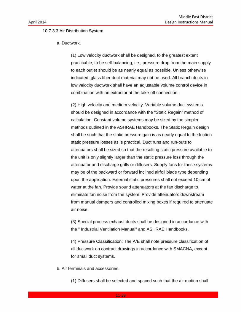
Middle East District April 2014 Design Instructions Manual
10.7.3.3 Air Distribution System.
a. Ductwork.
(1) Low velocity ductwork shall be designed, to the greatest extent
practicable, to be self-balancing, i.e., pressure drop from the main supply
to each outlet should be as nearly equal as possible. Unless otherwise
indicated, glass fiber duct material may not be used. All branch ducts in
low velocity ductwork shall have an adjustable volume control device in
combination with an extractor at the take-off connection.
(2) High velocity and medium velocity. Variable volume duct systems
should be designed in accordance with the "Static Regain" method of
calculation. Constant volume systems may be sized by the simpler
methods outlined in the ASHRAE Handbooks. The Static Regain design
shall be such that the static pressure gain is as nearly equal to the friction
static pressure losses as is practical. Duct runs and run-outs to
attenuators shall be sized so that the resulting static pressure available to
the unit is only slightly larger than the static pressure loss through the
attenuator and discharge grills or diffusers. Supply fans for these systems
may be of the backward or forward inclined airfoil blade type depending
upon the application. External static pressures shall not exceed 10 cm of
water at the fan. Provide sound attenuators at the fan discharge to
eliminate fan noise from the system. Provide attenuators downstream
from manual dampers and controlled mixing boxes if required to attenuate
air noise.
(3) Special process exhaust ducts shall be designed in accordance with
the " Industrial Ventilation Manual" and ASHRAE Handbooks.
(4) Pressure Classification: The A/E shall note pressure classification of
all ductwork on contract drawings in accordance with SMACNA, except
for small duct systems.
b. Air terminals and accessories.
(1) Diffusers shall be selected and spaced such that the air motion shall
11-23

Middle East District April 2014 Design Instructions Manual
not exceed more than 25.2 mpm at the occupied level and area covered
by the diffuser. In general, supply outlets shall be selected with throw
equal to three-fourths of the total distance required at a terminal velocity
of 30.5 mpm.
(2) Exhaust or return air outlets shall be provided to permit the free flow of
air from the conditioned area. Power exhaust or return air fans shall be
used whenever necessitated by system design. The exhaust shall be
drawn from hot or contaminated locations (kitchens, battery storage
areas, toilets, etc.) whenever feasible. If the quality and temperature are
acceptable, ventilated air may be used for condensers or engine radiator
cooling.
(3) Supply and exhaust air quantities shall be balanced to maintain a
slight positive pressure in the building. Wherever convenient, corridors
and stairwells shall be pressurized in order to minimize the entry of
smoke due to fire. Where variable air volume (VAV) systems are used or
where pressure is critical, volumetric type pressure controls shall be used
to set and control the pressure.
(4) Volume control dampers (where the size and shape of the duct
permits) shall be of the multi-louver opposed blade type and shall be the
standard product of a recognized air distribution equipment manufacturer.
(5) Sound attenuators and/or acoustical duct lining shall be provided as
required to maintain room noise criteria (NC) as recommended in the
ASHRAE Handbooks.
(6) Turning vanes shall be double blade and the standard product of a
recognized air distribution equipment manufacturer.
(7) Control dampers shall not be sized according to the duct size. They
shall be sized to provide the pressure drop which will result in the most
linear performance curve. Damper sizing, including a copy of the
manufacturer's sizing tables, shall be included in the design analysis.
10.7.3.4 Air Filtration.
11-24

Middle East District April 2014 Design Instructions Manual
a. Design Considerations.
(1) Degree of collection required. Clean country air contains less than 2.0
x 10-7 kg of largely harmless organic dust per cubic meter of air. Such air
requires no filtration system beyond an insect screen. The permissible
concentration of dust in the discharge air of the HVAC supply air should
not exceed 0.187 x 10⁻⁷ pcf, 0.3 mg/m
3. The outside air quality and intake
location determines the type of air filtration system required.
(2) Outside air intakes should be located as high as practical (preferably
over 8 meters) but within reasonable architectural constraints. Where
outside air intakes must be located below 3 meters, a consideration will
be given to providing inertial separators as a first stage filter. In special
use building areas or facilities, activated carbon filters or other types of
special filters shall be employed for removal of odor, tobacco smoke, and
bacteria during the 100% recirculation operation of the HVAC system.
(3) Economizer cycles are not recommended for use in the Middle East
because of high air filter maintenance requirements and limited benefits
of reducing refrigeration equipment operation. Use of economizer cycles
may be granted by MED if feasible and requested by the A/E.
b. Filtration Equipment: Air intake systems shall be designed with air filtration
equipment as follows unless specific design conditions warrant that a waiver be
requested of MED. If such a waiver cannot be obtained from MED, air filtration
systems for all projects shall consist of three stages as described below.
(1) First Stage Filtration: At locations where sandstorm and dust storm
frequency is low and there is no need for an efficient pre-cleaner, weather
louvers without inertial separators will be used for outside air intakes and
shall serve as a first stage of filtration. Where sandstorm and dust storm
frequency is high, weather louvers with inertial separators are required as
the first stage filter for outside air. Therefore, weather louvers and inertial
separators are required in areas of high sandstorm and dust-storm
frequency and are also required for all locations if the outside air intakes
11-25
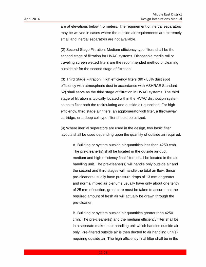
Middle East District April 2014 Design Instructions Manual
are at elevations below 4.5 meters. The requirement of inertial separators
may be waived in cases where the outside air requirements are extremely
small and inertial separators are not available.
(2) Second Stage Filtration: Medium efficiency type filters shall be the
second stage of filtration for HVAC systems. Disposable media roll or
traveling screen wetted filters are the recommended method of cleaning
outside air for the second stage of filtration.
(3) Third Stage Filtration: High efficiency filters (80 - 85% dust spot
efficiency with atmospheric dust in accordance with ASHRAE Standard
52) shall serve as the third stage of filtration in HVAC systems. The third
stage of filtration is typically located within the HVAC distribution system
so as to filter both the recirculating and outside air quantities. For high
efficiency, third stage air filters, an agglomerator-roll filter, a throwaway
cartridge, or a deep cell type filter should be utilized.
(4) Where inertial separators are used in the design, two basic filter
layouts shall be used depending upon the quantity of outside air required.
A. Building or system outside air quantities less than 4250 cmh.
The pre-cleaner(s) shall be located in the outside air duct;
medium and high efficiency final filters shall be located in the air
handling unit. The pre-cleaner(s) will handle only outside air and
the second and third stages will handle the total air flow. Since
pre-cleaners usually have pressure drops of 13 mm or greater
and normal mixed air plenums usually have only about one tenth
of 25 mm of suction, great care must be taken to assure that the
required amount of fresh air will actually be drawn through the
pre-cleaner.
B. Building or system outside air quantities greater than 4250
cmh. The pre-cleaner(s) and the medium efficiency filter shall be
in a separate makeup air handling unit which handles outside air
only. Pre-filtered outside air is then ducted to air handling unit(s)
requiring outside air. The high efficiency final filter shall be in the
11-26

Middle East District April 2014 Design Instructions Manual
main air handling unit handling the total air flow. Medium efficiency
filters are not required upstream of the third stage filters in the air
handling unit in this case.
c. Panel filters for HVAC systems shall be of the throw-away or disposable type.
Panel filters may be used as second stage filters.
10.7.3.5 Cleaning, Flushing, Testing and Water Treatment. The chilled water system
shall be designed to facilitate system flushing, testing, and balancing. Provisions must be made
to add corrosion and scale inhibitors in closed loop chilled water systems. The water that would
be used for system flush, test, final fill, and make up shall be of quality no less then that required
by International Standard for drinking water. See table below:
___________________________________________________________________
INTERNATIONAL STANDARD FOR DRINKING WATER
(l) Constituent International Standard Limit
Calcium (Ca+) 75-200 mg/1
Magnesium (Mg++) 30-150(2) mg/1
Sodium (Na+) & Potassium -- --
(K+) (expressed as Na+)
Biacarbonate (HCO3) -- --
Arsenic (As) 0.05 mg/1
Carbonate (CO3) -- --
Cadmium (Cd) 0.01 mg/1
Hydroxide (OH-) -- --
Cyanide (CN) 0.05 mg/1
Sulfate (SO4=) 200-400 mg/1
11-27
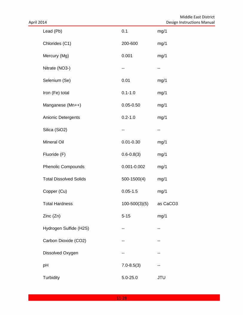
Middle East District April 2014 Design Instructions Manual
Lead (Pb) 0.1 mg/1
Chlorides (C1) 200-600 mg/1
Mercury (Mg) 0.001 mg/1
Nitrate (NO3-) -- --
Selenium (Se) 0.01 mg/1
Iron (Fe) total 0.1-1.0 mg/1
Manganese (Mn++) 0.05-0.50 mg/1
Anionic Detergents 0.2-1.0 mg/1
Silica (SiO2) -- --
Mineral Oil 0.01-0.30 mg/1
Fluoride (F) 0.6-0.8(3) mg/1
Phenolic Compounds 0.001-0.002 mg/1
Total Dissolved Solids 500-1500(4) mg/1
Copper (Cu) 0.05-1.5 mg/1
Total Hardness 100-500(3)(5) as CaCO3
Zinc (Zn) 5-15 mg/1
Hydrogen Sulfide (H2S) -- --
Carbon Dioxide (CO2) -- --
Dissolved Oxygen -- --
pH 7.0-8.5(3) --
Turbidity 5.0-25.0 JTU
11-28
Middle East District April 2014 Design Instructions Manual
Color Clear, (6) --
Notes:
(l) Constituent International Standard Limit
(1) Lower figure is desirable maximum, higher figure is maximum permissible.
(2) If there are at least 250 mg/l of sulfates, the maximum limit of magnesium is 30 mg/l,
otherwise the limit is 125 mg/l.
(3) Lower figure is recommended minimum, higher is recommended maximum.
(4) Calculated by summation of ions plus uncharged substances.
(5) Calculated from Ca++
and Mg++
concentrations.
(6) After 8 to 10 hours water exhibits yellowish color due to iron oxidation.
(7) All values are as ion unless otherwise noted.
______________________________________________________________________
10.7.3.6 Control Systems.
a. HVAC controls based on standard control strategies and standard system
control panels using single loop digital controllers or DDC controls shall be
provided for all projects as is appropriate for the project location. Technical
Manual (TM 5-815-3) providing criteria for HVAC single loop digital control
systems shall be used for guidance.
b. A complete sequence of operation shall be included on the drawings along
with a schematic control diagram for each typical system. The sequence of
operation and schematic control diagrams shall specifically cover the following
items and others as the project requires.
(1) Refrigeration compressor control.
(2) Refrigeration system protective devices.
11-29

Middle East District April 2014 Design Instructions Manual
(3) Chilled water and DX system controls.
(4) Water coil or evaporator coil control;
temperature and/or humidity as required.
(5) Air-cooled condenser control.
(6) Air handling unit control with protective
devices.
(7) Individual unit control.
(8) Motor interlocks for each system component
along with starting and stopping instructions.
(9) All thermostat, humidistat, and protective
device control settings.
(10) Chilled water pump and flow controls for
each building.
c. Central plant control will generally be manual through a hard wired control
panel. Chillers, pumps, and other equipment in general will be started and
stopped manually.
d. Air cooled chillers shall be specified to include a high ambient temperature
control of some type. This control shall be inoperative up to 50oC. When the
ambient air temperature rises above 50oC, this control will activate to sense head
pressure and unload the compressors if required to maintain head pressures
below the settings of the high pressure cut-out control. This control shall be
furnished by the chiller manufacturer and shall be built into the chiller control
panel.
e. Condenser water temperature. In general, the temperature of the cooling tower
11-30
Middle East District April 2014 Design Instructions Manual
water entering the condenser shall not be controlled, i.e., the temperature shall
not be maintained at the design figure but shall be allowed to drop as the system
load and the ambient wet bulb temperatures drop. Cooling tower fans shall be
cycled from the temperature of the water in the cooling tower sump. The
minimum allowable condenser entering water temperature shall be determined
by the chiller manufacturer. When the minimum temperature is approached, a
control valve shall be used to bypass some condenser leaving water back to the
condenser pump inlet to maintain the condenser inlet water temperature safely
above the minimum allowable.
f. Variable air volume systems generally use inlet vane control. However, if the
system selected is by a manufacturer who uses "run around" rather than inlet
vane control, it is acceptable provided that the entire air distribution system is
specified to be procured from this manufacturer.
10.7.3.7 Electric Motors. All motors exposed to 40.5oC temperature or greater shall be of
the totally enclosed fan cooled (TEFC) type continuous duty classifications based upon 50oC
ambient temperature of reference. Cooling tower applications, where vertical turbine pumps are
used, electrical motor enclosures shall be equipped with strip heaters in order to avoid
condensation due to dirernal temperature difference.
10.7.4 Site Utilities.
10.7.4.1 Thermal Expansion must be considered and accounted for in straight runs of
piping. Allowable stress ranges are given in ANSI B31.1.
10.7.4.2 Anchors. Anchors shall be required where there is a change in direction,
diameter, or wall thickness of a pipeline that may cause undesired movement, loads, or stress
and whenever buckling of the pipe may occur. For buried piping, no credit may be taken for
resisting friction between the pipe and the soil since the full development of this force does not
occur when line movement is prevented. Anchors may be concrete or piling type.
10.7.4.3 The Minimum Depth of buried piping shall be 622 mm. Roads and changes in
slope shall be considered where applicable.
10.7.4.4 Routing of pipes shall be in groups wherever possible.
11-31

Middle East District April 2014 Design Instructions Manual
10.7.5 Equipment and Design Data Schedules. The following equipment and general
design parameters and information shall be provided on the mechanical equipment schedule
drawings. Each schedule shall neatly provide sufficient space to include all applicable
information required. The applicable mechanical equipment schedules shall be submitted, as
hereinbefore described, on the preliminary and final submittal drawings.
11-32
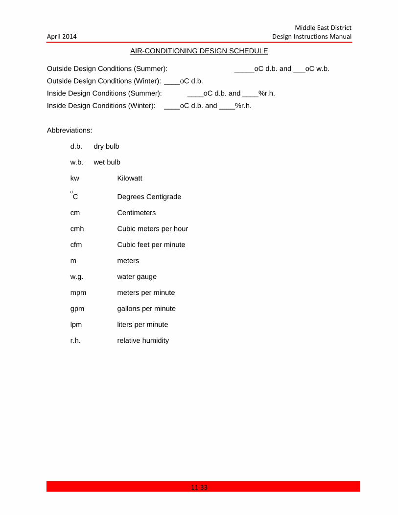
Middle East District April 2014 Design Instructions Manual
AIR-CONDITIONING DESIGN SCHEDULE Outside Design Conditions (Summer): _____oC d.b. and ___oC w.b.
Outside Design Conditions (Winter): ____oC d.b.
Inside Design Conditions (Summer): ____oC d.b. and ____%r.h.
Inside Design Conditions (Winter): ____oC d.b. and ____%r.h.
Abbreviations:
d.b. dry bulb
w.b. wet bulb
kw Kilowatt
oC Degrees Centigrade
cm Centimeters
cmh Cubic meters per hour
cfm Cubic feet per minute
m meters
w.g. water gauge
mpm meters per minute
gpm gallons per minute
lpm liters per minute
r.h. relative humidity
11-33
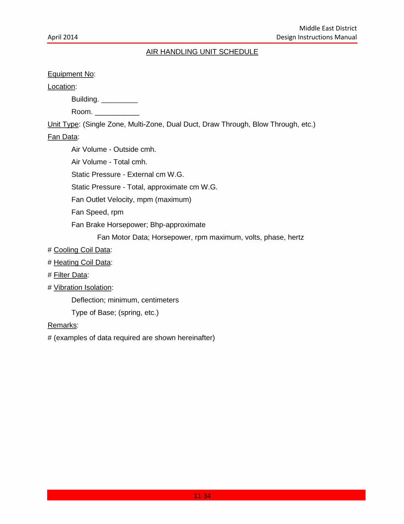
Middle East District April 2014 Design Instructions Manual
AIR HANDLING UNIT SCHEDULE
Equipment No:
Location:
Building. _________
Room. ___________
Unit Type: (Single Zone, Multi-Zone, Dual Duct, Draw Through, Blow Through, etc.)
Fan Data:
Air Volume - Outside cmh.
Air Volume - Total cmh.
Static Pressure - External cm W.G.
Static Pressure - Total, approximate cm W.G.
Fan Outlet Velocity, mpm (maximum)
Fan Speed, rpm
Fan Brake Horsepower; Bhp-approximate
Fan Motor Data; Horsepower, rpm maximum, volts, phase, hertz
# Cooling Coil Data:
# Heating Coil Data:
# Filter Data:
# Vibration Isolation:
Deflection; minimum, centimeters
Type of Base; (spring, etc.)
Remarks:
# (examples of data required are shown hereinafter)
11-34
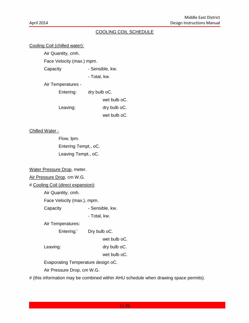
Middle East District April 2014 Design Instructions Manual
COOLING COIL SCHEDULE
Cooling Coil (chilled water):
Air Quantity, cmh.
Face Velocity (max.) mpm.
Capacity - Sensible, kw.
- Total, kw.
Air Temperatures -
Entering: dry bulb oC.
wet bulb oC.
Leaving: dry bulb oC.
wet bulb oC.
Chilled Water -
Flow, lpm.
Entering Tempt., oC.
Leaving Tempt., oC.
Water Pressure Drop, meter.
Air Pressure Drop, cm W.G.
# Cooling Coil (direct expansion):
Air Quantity, cmh.
Face Velocity (max.), mpm.
Capacity - Sensible, kw.
- Total, kw.
Air Temperatures:
Entering:` Dry bulb oC.
wet bulb oC.
Leaving: dry bulb oC.
wet bulb oC.
Evaporating Temperature design oC.
Air Pressure Drop, cm W.G.
# (this information may be combined within AHU schedule when drawing space permits).
11-35
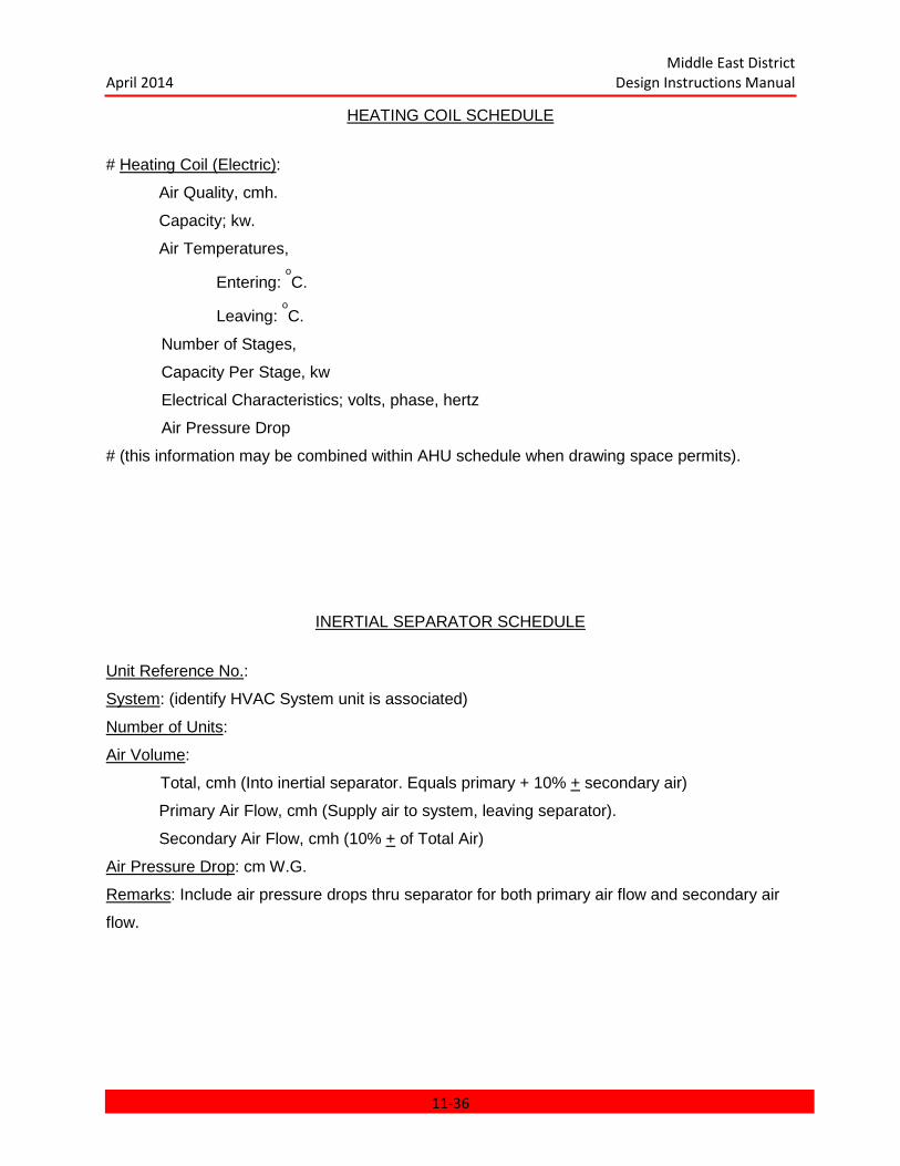
Middle East District April 2014 Design Instructions Manual
HEATING COIL SCHEDULE
# Heating Coil (Electric):
Air Quality, cmh.
Capacity; kw.
Air Temperatures,
Entering: oC.
Leaving: oC.
Number of Stages,
Capacity Per Stage, kw
Electrical Characteristics; volts, phase, hertz
Air Pressure Drop
# (this information may be combined within AHU schedule when drawing space permits).
INERTIAL SEPARATOR SCHEDULE
Unit Reference No.:
System: (identify HVAC System unit is associated)
Number of Units:
Air Volume:
Total, cmh (Into inertial separator. Equals primary + 10% + secondary air)
Primary Air Flow, cmh (Supply air to system, leaving separator).
Secondary Air Flow, cmh (10% + of Total Air)
Air Pressure Drop: cm W.G.
Remarks: Include air pressure drops thru separator for both primary air flow and secondary air
flow.
11-36
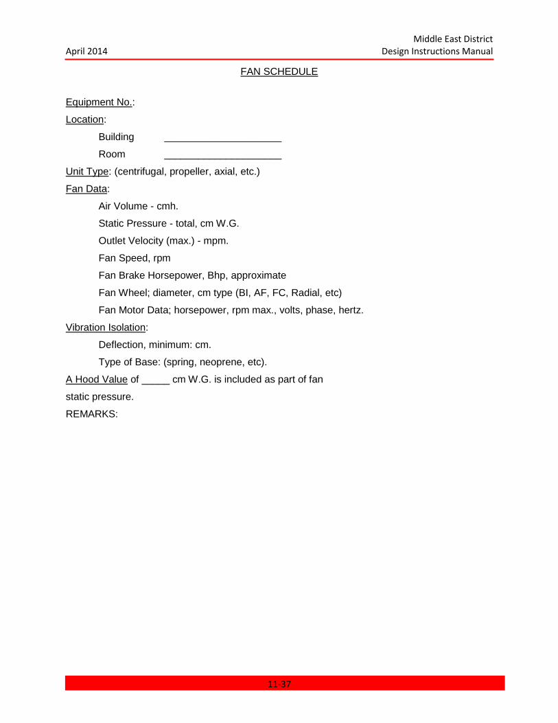
Middle East District April 2014 Design Instructions Manual
FAN SCHEDULE
Equipment No.:
Location:
Building _____________________
Room _____________________
Unit Type: (centrifugal, propeller, axial, etc.)
Fan Data:
Air Volume - cmh.
Static Pressure - total, cm W.G.
Outlet Velocity (max.) - mpm.
Fan Speed, rpm
Fan Brake Horsepower, Bhp, approximate
Fan Wheel; diameter, cm type (BI, AF, FC, Radial, etc)
Fan Motor Data; horsepower, rpm max., volts, phase, hertz.
Vibration Isolation:
Deflection, minimum: cm.
Type of Base: (spring, neoprene, etc).
A Hood Value of _____ cm W.G. is included as part of fan
static pressure.
REMARKS:
11-37

Middle East District April 2014 Design Instructions Manual
EXHAUST HOOD SCHEDULE (Kitchen, Fume, Machine, etc)
Unit Reference No:
Location:
Building: ___________________
Room: ___________________
Fan: ___________________
Filters: See info - "Filter Schedule" and include (as applicable)
Air Volume: cmh
Hood Static Pressure Loss: cm W.G.
(a) Exhaust Side
(b) Supply Side
PUMP SCHEDULE
Equipment No.:
Location:
Building ____________________
Room ____________________
Service: (chilled water, hot water, etc.)
(Operating, standby, etc.)
Unit Type: (Centrifugal, etc.)
Pump Data:
Flow Rate, lpm.
Head, meters.
Efficiency Pump Motor Data; horsepower, rpm, volts, phase, hertz
Remarks:
11-38

Middle East District April 2014 Design Instructions Manual
WATER CHILLER SCHEDULE
Equipment No.:
Location:
Building _______________
Room _______________
Operating Function: (operating or standby)
Unit Type: (air cooled centrifugal, etc.)
Tonnage, Nominal:
Input, KW:
Chiller Cooler (evaporator) Data:
Flow Rate, lpm.
Water Temperatures, entering _____ oC, leaving _____ oC.
Number of Passes.
Pressure Drop, meters.
Fouling Factor.
Chiller Condenser Data (Air Cooled):
Number of condenser fans.
Air Temperatures, entering _____ oC, leaving _____ oC.
Fan Drive, (direct, belt).
Fan Motor Data, horsepower, rpm, volts, phase, hertz.
Chilled Condenser Data (Water Cooled).
Water flow rate.
Water temperature
entering _____ oC, leaving _____ oC.
Pressure drop, meters.
Fouling factor.
Remarks:
11-39
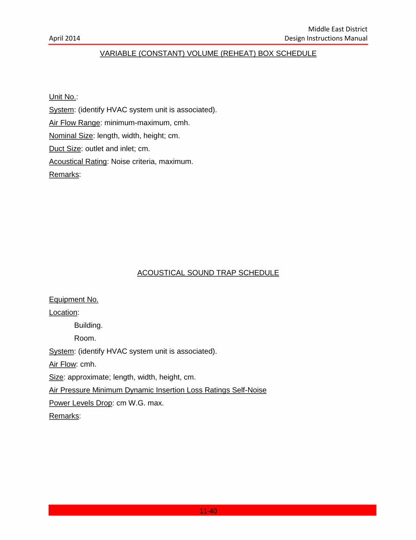
Middle East District April 2014 Design Instructions Manual
VARIABLE (CONSTANT) VOLUME (REHEAT) BOX SCHEDULE
Unit No.:
System: (identify HVAC system unit is associated).
Air Flow Range: minimum-maximum, cmh.
Nominal Size: length, width, height; cm.
Duct Size: outlet and inlet; cm.
Acoustical Rating: Noise criteria, maximum.
Remarks:
ACOUSTICAL SOUND TRAP SCHEDULE
Equipment No.
Location:
Building.
Room.
System: (identify HVAC system unit is associated).
Air Flow: cmh.
Size: approximate; length, width, height, cm.
Air Pressure Minimum Dynamic Insertion Loss Ratings Self-Noise
Power Levels Drop: cm W.G. max.
Remarks:
11-40
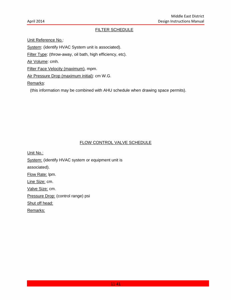
Middle East District April 2014 Design Instructions Manual
FILTER SCHEDULE Unit Reference No.:
System: (identify HVAC System unit is associated).
Filter Type: (throw-away, oil bath, high efficiency, etc).
Air Volume: cmh.
Filter Face Velocity (maximum), mpm.
Air Pressure Drop (maximum initial): cm W.G.
Remarks:
(this information may be combined with AHU schedule when drawing space permits).
FLOW CONTROL VALVE SCHEDULE Unit No.:
System: (identify HVAC system or equipment unit is
associated).
Flow Rate: lpm.
Line Size: cm.
Valve Size: cm.
Pressure Drop: (control range) psi
Shut off head:
Remarks:
11-41
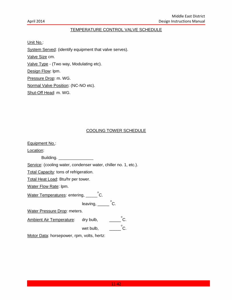
Middle East District April 2014 Design Instructions Manual
TEMPERATURE CONTROL VALVE SCHEDULE
Unit No.:
System Served: (identify equipment that valve serves).
Valve Size cm.
Valve Type - (Two way, Modulating etc).
Design Flow: lpm.
Pressure Drop: m. WG.
Normal Valve Position: (NC-NO etc).
Shut-Off Head: m. WG.
COOLING TOWER SCHEDULE
Equipment No.:
Location:
Building. _______________
Service: (cooling water, condenser water, chiller no. 1, etc.).
Total Capacity: tons of refrigeration.
Total Heat Load: Btu/hr per tower.
Water Flow Rate: lpm.
Water Temperatures: entering, _____oC.
leaving, _____ oC.
Water Pressure Drop: meters.
Ambient Air Temperature: dry bulb, _____oC.
wet bulb, _____oC.
Motor Data: horsepower, rpm, volts, hertz:
11-42

Middle East District April 2014 Design Instructions Manual
CHAPTER 11
PLUMBING
CHAPTER 11 PLUMBING ................................................................................................... 11-1 11.1 GENERAL .................................................................................................................... 11-3
11.1.1 Scope .................................................................................................................... 11-3 11.1.2 Document Requirements ....................................................................................... 11-3
11.2 APPLICABLE PUBLICATIONS .................................................................................... 11-3 11.3 CONCEPT SUBMITTAL REQUIREMENTS ................................................................. 11-4
11.3.1 General Considerations ......................................................................................... 11-4 11.3.2 Concept Design Analysis ....................................................................................... 11-4
11.4 PRELIMINARY REVIEW SUBMITTAL REQUIREMENTS ............................................ 11-5 11.4.1 Preliminary Design Analysis .................................................................................. 11-5 11.4.2 Preliminary Design Drawings ................................................................................. 11-5 11.4.3 Equipment Schedules ............................................................................................ 11-6
11.5 FINAL REVIEW SUBMITTAL REQUIREMENTS .......................................................... 11-6 11.5.1 Final Design Analysis ............................................................................................ 11-6 11.5.2 Final Design Drawings ........................................................................................... 11-6 11.5.3 Catalog Cuts .......................................................................................................... 11-7
11.6 READY TO ADVERTISE (RTA) ................................................................................... 11-7 11.7 TECHNICAL REQUIREMENTS ................................................................................... 11-7
11.7.1 Packaged Equipment ............................................................................................. 11-7 11.7.2 Existing Services ................................................................................................... 11-7 11.7.3 Soil Surveys........................................................................................................... 11-7 11.7.4 Sanitary and Roof Drainage Systems .................................................................... 11-8 11.7.5 Water Supply System ............................................................................................ 11-8 11.7.6 Piping System ...................................................................................................... 11-16 11.7.7 Plumbing Fixtures ................................................................................................ 11-17 11.7.8 Pipe Protection .................................................................................................... 11-18 11.7.9 Seismic Design .................................................................................................... 11-18 11.7.10 Noise Control ..................................................................................................... 11-18 11.7.12 Compressed Air and Vacuum Systems .............................................................. 11-19 11.7.13 Fuel Gas Piping ................................................................................................. 11-19 11.7.14 Equipment and Fixture Schedules ..................................................................... 11-19
PLUMBING FIXTURE SCHEDULE .................................................................................... 11-20 WATER HEATER SCHEDULE .......................................................................................... 11-21 HOT WATER STORAGE TANK SCHEDULE .................................................................... 11-22 WATER COOLER SCHEDULE .......................................................................................... 11-22 PUMP SCHEDULE ............................................................................................................ 11-23 AIR COMPRESSOR SCHEDULE ...................................................................................... 11-24
11-1

Middle East District April 2014 Design Instructions Manual
#MISCELLANEOUS EQUIPMENT CONNECTION SCHEDULE ........................................ 11-25 11.8 Abbreviations ............................................................................................................. 11-26
11-2
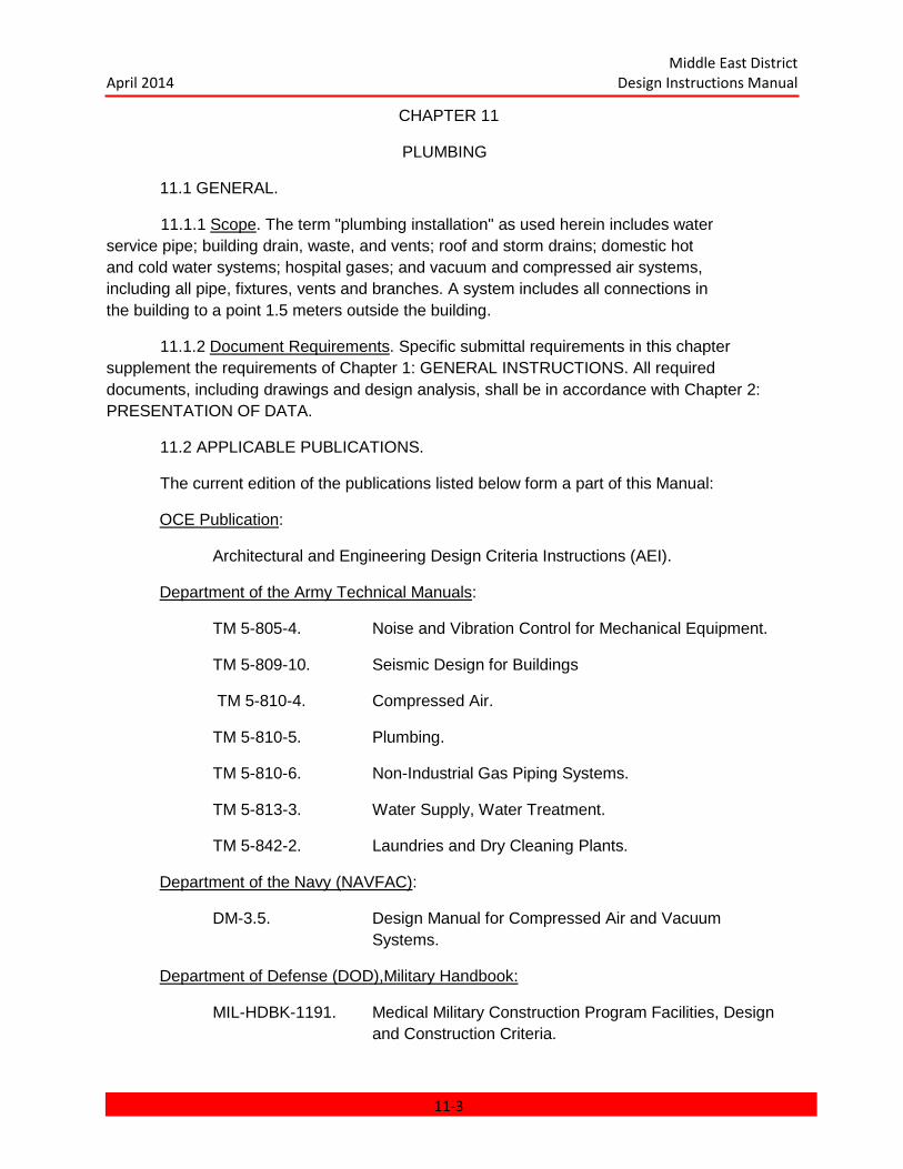
Middle East District April 2014 Design Instructions Manual
CHAPTER 11
PLUMBING
11.1 GENERAL.
11.1.1 Scope. The term "plumbing installation" as used herein includes water service pipe; building drain, waste, and vents; roof and storm drains; domestic hot and cold water systems; hospital gases; and vacuum and compressed air systems, including all pipe, fixtures, vents and branches. A system includes all connections in the building to a point 1.5 meters outside the building.
11.1.2 Document Requirements. Specific submittal requirements in this chapter supplement the requirements of Chapter 1: GENERAL INSTRUCTIONS. All required documents, including drawings and design analysis, shall be in accordance with Chapter 2: PRESENTATION OF DATA.
11.2 APPLICABLE PUBLICATIONS.
The current edition of the publications listed below form a part of this Manual:
OCE Publication:
Architectural and Engineering Design Criteria Instructions (AEI).
Department of the Army Technical Manuals:
TM 5-805-4. Noise and Vibration Control for Mechanical Equipment.
TM 5-809-10. Seismic Design for Buildings
TM 5-810-4. Compressed Air.
TM 5-810-5. Plumbing.
TM 5-810-6. Non-Industrial Gas Piping Systems.
TM 5-813-3. Water Supply, Water Treatment.
TM 5-842-2. Laundries and Dry Cleaning Plants.
Department of the Navy (NAVFAC):
DM-3.5. Design Manual for Compressed Air and Vacuum Systems.
Department of Defense (DOD),Military Handbook:
MIL-HDBK-1191. Medical Military Construction Program Facilities, Design and Construction Criteria.
11-3
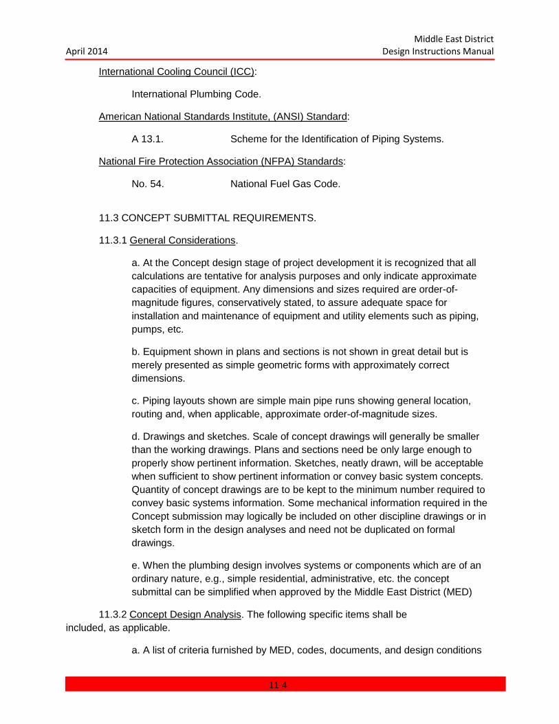
Middle East District April 2014 Design Instructions Manual
International Cooling Council (ICC):
International Plumbing Code.
American National Standards Institute, (ANSI) Standard:
A 13.1. Scheme for the Identification of Piping Systems.
National Fire Protection Association (NFPA) Standards:
No. 54. National Fuel Gas Code.
11.3 CONCEPT SUBMITTAL REQUIREMENTS.
11.3.1 General Considerations.
a. At the Concept design stage of project development it is recognized that all calculations are tentative for analysis purposes and only indicate approximate capacities of equipment. Any dimensions and sizes required are order-of-magnitude figures, conservatively stated, to assure adequate space for installation and maintenance of equipment and utility elements such as piping, pumps, etc.
b. Equipment shown in plans and sections is not shown in great detail but is merely presented as simple geometric forms with approximately correct dimensions.
c. Piping layouts shown are simple main pipe runs showing general location, routing and, when applicable, approximate order-of-magnitude sizes.
d. Drawings and sketches. Scale of concept drawings will generally be smaller than the working drawings. Plans and sections need be only large enough to properly show pertinent information. Sketches, neatly drawn, will be acceptable when sufficient to show pertinent information or convey basic system concepts. Quantity of concept drawings are to be kept to the minimum number required to convey basic systems information. Some mechanical information required in the Concept submission may logically be included on other discipline drawings or in sketch form in the design analyses and need not be duplicated on formal drawings.
e. When the plumbing design involves systems or components which are of an ordinary nature, e.g., simple residential, administrative, etc. the concept submittal can be simplified when approved by the Middle East District (MED)
11.3.2 Concept Design Analysis. The following specific items shall be included, as applicable.
a. A list of criteria furnished by MED, codes, documents, and design conditions
11-4
Middle East District April 2014 Design Instructions Manual
used; references to any authorized waiver of criteria and codes.
b. Tentative calculations and sizing of domestic hot and cold water, sanitary, roof drainage, compressed air, vacuum, fuel gas, water treatment, and special gas systems.
c. Description, approximate capacity, and location of all miscellaneous equipment such as air compressors, vacuum pumps, water treatment softeners, water heaters, fuel gas storage tanks, etc., to be installed in the project.
d. Hot water and fuel gas demand analysis, including hourly heating capacity, hourly requirements, and storage capacity.
11.3.3 Concept Design Drawings. The plans shall be sufficiently complete to show locations and the general arrangement of plumbing fixtures and major plumbing system equipment.
11.4 PRELIMINARY REVIEW SUBMITTAL REQUIREMENTS.
11.4.1 Preliminary Design Analysis. The Preliminary design analysis shall include all items in the Concept design analysis and any necessary revisions. In addition, the following specific items shall be included when applicable.
a. Detailed calculations for sizing equipment, piping, water treatment systems, etc. for each plumbing system involved in the design.
b. Data showing the capacity of hot and domestic potable water circulating or booster pumps (where required).
c. Any other information or computations required to permit verification that the design complies with the design criteria, codes, and standards and is satisfactory for the intended purpose.
d. Catalog Cuts. As a minimum catalog cuts for all major items of equipment shall be submitted. Catalog cuts shall be a part of the design analysis.
11.4.2 Preliminary Design Drawings. The plans shall include, but not be limited to the following:
a. Enlarged partial plans and riser diagrams of typical toilet rooms including hot water, cold water, waste, and vent piping.
b. Locations and arrangement of all plumbing fixtures and equipment.
c. Layout of domestic water, sewer, roof drainage, and all other piping systems used in the building, including sections and details, especially of congested areas, etc.
d. Flow diagrams of compressed air systems including all equipment such as air
11-5

Middle East District April 2014 Design Instructions Manual
compressors, accessories, pipe, tubing, and control valve actuators or any other equipment to which air is supplied.
e. Since equipment rooms represent the most congested areas for both equipment and piping. The drawings shall represent by enlarged partial plans, sections, and details that sufficient removal, maintenance, replacement, and installation space has been provided.
f. Vertical control for horizontal runs of piping, etc. shall be clearly delineated on the drawings. The drawings, by sections, elevations, or notes, shall show vertical control of piping. The design shall ensure sufficient vertical clear height has been provided.
11.4.3 Equipment Schedules. The final form of all equipment schedules which will be included in the project shall be shown with Preliminary equipment data filled in.
11.5 FINAL REVIEW SUBMITTAL REQUIREMENTS.
11.5.1 Final Design Analysis. The design analysis shall include all of the information required in the Preliminary submittal but in its final form, any additional information required, and also the information listed below when applicable.
a. All textbooks, handbooks, and other references used in the design analysis shall be cited, giving page and paragraph numbers from which data is obtained.
b. The basis of sizing water treatment system shall be presented.
c. Pump lpm, TDH, and horsepower calculations shall be shown for potable drinking water, and hot water recirculating pumps. The friction losses in the water circuits and pipe sizing shall be tabulated for proper review.
d. The method of sizing hot water heaters, etc. shall be shown.
e. Equipment sizing calculations to support the selection of all equipment shall be shown in the design analysis.
f. Explanatory notes shall be included in the design analysis covering all rationale for design which would not be obvious to an engineer reviewing the analysis. The A-E shall review the prepared plans and specifications and determine that they are in accordance with this manual and all other criteria and instructions furnished by MED. It will be the responsibility of the designer to coordinate the plumbing systems with the other trades involved in the building design and to eliminate interference between plumbing equipment and other components of the building.
11.5.2 Final Design Drawings. Flow diagrams, riser diagrams, and plans containing all the necessary details to attract accurate and competitive bids and to afford a clear understanding throughout construction shall be included in the drawings. Plans shall be
11-6

Middle East District April 2014 Design Instructions Manual
complete in all respects, showing location of all equipment, piping, and accessories. Sections and details shall be provided as required to clearly show all aspects of the system design. The following specific items shall be included when applicable:
a. Schematic flow and/or riser diagrams of all systems.
b. Equipment room layouts and appropriate sections and details.
c. Pipe sizes.
d. Vertical control for horizontal runs of piping, etc. shall be clearly delineated on the drawings. The drawings, sections, elevations, or notes, shall show vertical control of piping and ductwork. The design shall ensure sufficient clear vertical height has been provided.
e. Equipment to be furnished and installed by others.
f. Equipment schedules giving capacities, working temperatures and pressures, and other pertinent data necessary to give a clear and concise description of all equipment.
11.5.3 Catalog Cuts. Complete catalog cuts and data sheets shall be submitted for all major items of equipment. Catalog cuts shall be a part of the design analysis.
11.6 READY TO ADVERTISE (RTA).
The comments generated during the Final design review shall be incorporated in the documents before they are submitted as RTA.
11.7 TECHNICAL REQUIREMENTS.
11.7.1 Packaged Equipment. Packaged equipment shall be used to the greatest extent possible to simplify specifying, purchasing, installation, and maintenance of equipment.
11.7.2 Existing Services. The location, elevation, etc., of all existing sewers, water mains, and other necessary services will be verified to ascertain that such services are adequate and that connection thereto is permissible. If the water supply pressure obtained from the water main is inadequate, a house tank or hydropneumatic system shall be provided. In the event that sanitary sewer or water services are not available or connections thereto are prohibited, an individual sewage disposal or water system shall be installed to adequately serve the building. Water flow tests on public hydrants shall be made to ascertain the adequacy of the fire protection water supply based on the water supply requirements in Chapter 18: WATER, WASTEWATER, AND SOLID WASTE SYSTEMS.
11.7.3 Soil Surveys, to determine the electrical resistivity and percolation characteristics of the soil and ground water information along the alinements of all proposed buried piping systems, shall be conducted. These surveys shall be conducted by MED when requested by
11-7

Middle East District April 2014 Design Instructions Manual
the Architect Engineer (A-E).
11.7.4 Sanitary and Roof Drainage Systems.
11.7.4.1 Storm and Sanitary Sewers. Requirements for storm drainage outside buildings are included in Chapter 6: SITE PLANNING AND LAYOUT. Roof and area drains shall be piped to storm drains wherever available. In no case shall drainage be directed to adjacent property without approval of MED. Interior downspouts from roof drains shall be entirely separated from the sanitary system inside of the building, even though they may connect to a combined city sewer.
11.7.4.2 Lift Stations and Backwater Valves. Special consideration should be given to insure against the possibility of sewage and water backup. See TM 5-810-5 for guidance.
11.7.4.3 Roof Drains. Design of roof drains shall be on the basis of one-hour rainfall and 25-year records (if available). It shall also be in accordance with the recommendations of the National Standard Plumbing Code. The extent of any water retention on the roof shall be coordinated with the structural engineer.
11.7.4.4 Compactor Area Drains. An area drain shall be provided in trash compactor areas.
11.7.4.5 Floor Drains. Floor drains shall be provided in all boiler and mechanical equipment rooms and adjacent to each emergency deluge shower in addition to all areas listed as requiring floor drains in TM 5-810-5. Provide at least one floor drain with trap in each room with a water source, e.g., in kitchens, toilets, and tea rooms. Where fire pumps are installed having conventional packing glands, floor drains with dedicated gland leak-off piping shall also be provided.
11.7.4.6 Grease Interceptors shall be installed outside of buildings in accordance with TM 5-810-5.
11.7.4.7 Garbage Can Washing Facilities, including hot water booster heater shall be provided on the kitchen loading platform or in other suitable space adjacent to the kitchen service doors.
11.7.5 Water Supply System. For guidance additional to the paragraphs below, refer to Chapter 18: WATER, WASTEWATER, AND SOLID WASTE SYSTEMS.
11.7.5.1 Water Treatment. The A-E shall provide recommendations as to the chemical treatment system required for the following special facilities. The systems recommended shall be based upon an evaluation of the existing site water quality analysis.
a. Laundry softening is required where the water supply has a total hardness of 86 ppm or more, in accordance with TM 5-842-1.
b. Dishwashing for Mess Halls. Softening is required where the water supply has
11-8

Middle East District April 2014 Design Instructions Manual
a total hardness of 86 ppm or more, in accordance with TM 5-813-3.
c. Hospitals. Softening is required where the water supply has a total hardness of 171 ppm or more, in accordance with TM 5-838-2.
d. Aircraft/Vehicle Wash Facilities.
e. Humidifiers.
11.7.5.2 Water Usage. In all locations, the minimum acceptable level of water usage shall be maintained. Consideration should be given to methods that will preserve fresh water supplies, and minimum water treatment.
11.7.5.3 Dual Distribution Network. Where dual site water distribution networks exist and are approved for use within buildings, i.e., one raw or hard water main and one treated or soft water main, two separate cold water piping systems shall be installed as follows.
a. All facilities. Hard water shall be supplied to water closets and urinals.
b. Public facilities. Hard potable water shall be supplied to sinks and lavatories; soft water shall be supplied to drinking fountains and hot water heaters.
c. Living quarters (private or hotels). Soft water shall be supplied to both cold water faucets and hot water heaters.
11.7.5.4 Metering. In general, provide separate metering for each building on site, including single family housing units, except for small structures such as guard houses, sheds, etc.
11.7.5.5 Backflow Prevention. The water distribution system shall be protected against the flow of water or other liquids into the distributing pipes from any source or sources other than their intended flow. Refer to the International Plumbing Code for requirements on all systems.
11.7.5.6 Pressure Reducing Valves. Where excessive water pressures (above 448 KPa) are encountered, pressure reducing valves shall be installed to protect plumbing units or equipment which are inadequate to withstand such pressures. The valves shall be installed either on the building service line or on individual lines to the various units, whichever is more economically feasible.
11.7.5.7 Potable Water Outlets.
a. Water coolers (Drinking Water Dispensers) in work areas should be located out of the way of possible traffic aisles whenever possible. However, if located in the flow of traffic, they shall be provided with safety guard rails to protect user and fountain where shop type vehicles are used. Provide cold drinking water stations in the following locations:
(1) Near toilet rooms.
11-9

Middle East District April 2014 Design Instructions Manual
(2) In lunchrooms.
(3) In accordance with TM 5-810-5.
b. Water shall be chilled by standard packaged, self-contained water coolers (electric water coolers) with hot water heating capability as authorized. See TM 5-810-5 for drinking water consumption requirements.
c. Vending machine areas. Valved and capped potable cold water outlets shall be provided for vending machines at convenient locations in vending areas. Hot water for hot drinks may be incorporated with water coolers as authorized by MED.
11.7.5.8 Domestic Hot Water.
a. Shower system capacity. (See TM 5-810-5.) In the design of any buildings in which water closets and showers are installed, the designer shall exercise the necessary precautions to prevent personnel from being scalded while taking showers due to simultaneous operations of water closets equipped with flush valves. The final temperature for hot water supplied for showers shall not
exceed 43oC. It is suggested that consideration be given to the correction of this
condition by the methods listed hereinafter:
(1) Water supply line design. The water supply lines shall be designed to provide an adequate flow of water without excessive pressure drops.
(2) Separate water lines. Separate water supply lines shall be provided for the showers, so that a sudden demand on the water supply such as would be caused by the simultaneous flushing of flush valve equipped closets, will not affect the flow to the showers.
(3) Valves for showers. The showers shall be equipped with pressure-balancing mixing valves.
(4) "Mixed Water Temperature Control", in accordance with National Standard Plumbing Code.
b. Water heaters.
(1) Wherever commercial or industrial size domestic hot water heaters (as opposed to residential size) are supplied from a hard water line, a water softener shall be installed in the cold water line to the heater. All water softeners in individual buildings shall be of the automatic duplex type, so that there is no interruption of the soft water supply during backwash.
(2) The energy source for water heaters shall be electric. Other sources may be as indicated in TM 5-810-5 and as determined by availability and
11-10
Middle East District April 2014 Design Instructions Manual
economic considerations. Electric water heaters serving individual toilet rooms may be economically justified when toilet rooms are spaced far apart requiring long runs of piping or where venting is a problem. Where more than a 2,000-watt capacity is required, dual heater elements shall be specified to reduce instantaneous power demands.
(3) Check valves will not be placed on cold water inlet of water heaters.
c. Selection of piping materials and storage tanks. The selection of pipe, valves, fittings, materials and tanks will be in accordance with the quality of the water as classified in TM 5-810-5. Material selection must be coordinated with the project specifications.
d. Domestic hot water temperatures shall be in accordance with TM 5-810-5.
11.7.5.9 Hose Faucets (bibbs) and Lawn Faucets. All hose bibbs and lawn faucets shall be furnished with 15 mm water supply and standard hose type connections.
a. Exterior. Where buildings are located in grassed areas, lawn faucets shall be located so that watering may be accomplished using not more than 30 meters of hose and so that sprinkling can be accomplished without extending the hose over main walks and driving areas. A hose bibb with vacuum breaker shall be mounted adjacent to the cooling tower sump. A shutoff valve and drain shall be included in all areas if subject to freezing conditions.
b. Interior. Hose bibbs shall be provided at interior locations as follows and in other locations where required.
(1) At least one cold water hose bibb in mechanical equipment rooms housing central heating and refrigeration equipment.
(2) At least one cold water hose bibb at trash compactor areas.
(3) At least one hot water hose bibb at garbage storage locations.
(4) A cold water hose bibb in battery room for washdown of spills and leaks.
c. Vehicle maintenance facilities. Hose bibbs shall be provided in the following areas:
(1) At least one hose bibb for cold water service in the repair and lube area.
(2) At least one hose bibb at each gasoline servicing island. Provide a
frostproof type hydrant where the winter design temperature is -1oC. or
below.
11-11
Middle East District April 2014 Design Instructions Manual
(3) One hose bibb in each wash bay.
(4) An unthreaded hot water faucet three (3) feet above floor in the wash bay.
11.7.5.10 Emergency Deluge Showers and Eyewash Fountains. A deluge shower and combination eye-face wash fountain shall be provided in the following areas:
a. Any area where acid is handled, such as battery rooms.
b. The general vicinity of chemical water treatment feeders in the mechanical equipment rooms, or as required by the nature of the chemicals being handled, the form of the chemical (powder, liquid, etc.), and the type of feed equipment.
11.7.5.11 Swimming Pool Criteria.
a. Pipeless perimeter recirculation systems shall be used for all pools with surface areas of 325 square meters and less. Pipeless perimeter recirculation systems or systems using continuous overflow gutters and bottom inlets shall be used for all pools with surface areas greater than 325 square meters.
(1) Pipeless perimeter recirculation system: Pipeless perimeter recirculation systems shall be designed to store surge within the pool thus eliminating the need for a surge tank. Surge weirs shall operate without the use of electric or electronic probes or sensors. At least one skimming weir shall be provided for every
46 m2 of water surface area or fraction thereof, and each weir
shall be designed for a flow rate of at least 114 lpm at full flow.
(2) Continuous overflow gutter systems: Pool surge from continuous overflow gutters shall be stored in an external surge tank. Recirculation supply shall be from bottom inlets or from extruded Polyvinyl Chloride (PVC) conduit system imbedded in the racing lanes in the pool. (Bottom inlets shall be shown on the drawings as the base design). The continuous gutter drain shall be separated from the deck drainage system. Buried piping shall be minimized to the greatest extent possible. All piping under the pool bottom slab shall be encased in concrete.
b. Inlets from the recirculation system shall be flush with the pool walls or bottom and submerged at least 200 mm below the water level. An adequate number of inlets shall be provided to accomplish complete and uniform recirculation of the pool water. Gutter drain system shall be designed for 100% of recirculation flow to break up thermal stratification.
11-12
Middle East District April 2014 Design Instructions Manual
c. Main Drains shall be at least four times the area of the discharge pipe. Multiple outlets shall be provided where the width of the pool is more than 9 meters. Multiple outlets shall be spaced not more than 9 meters apart and not more than 5 meters from the side walls of the pool.
d. Hydrostatic relief valves shall be provided in areas where high water tables are anticipated. Pool drain lines shall discharge into the sanitary sewer or storm sewer through a suitable air gap. Pools shall drain at a rate not to exceed 100 mm per hour to allow the hydrostatic relief valves to relieve the pressure on the pool structure. Main drain lines shall be designed to carry 100% of the recirculation flow.
e. Pools shall be designed with a six hour turnover rate. Where wading facilities for children are provided, these areas shall be physically separated from the swimming pool and shall be designed with a two hour turnover rate.
f. The recirculation system shall be provided with a strainer to prevent hair, lint, etc., from reaching the pump and filters. Duplex pumps shall be provided with each pump sized for full flow. Whenever possible, pumps shall be located such that they shall have a flooded suction. Where this is not possible, pumps shall be self-priming.
g. Filter types in order of preference are as follows:
(1) Vacuum DE filters
(2) Rapid Sand filters
(3) High rate sand filters
A. High rate or rapid sand filters shall be used for all pools with surface areas of 325 square meters and less. Rapid sand or Vacuum diatomaceous Earth filters shall be used for all pools with surface areas greater than 325 square meters. Maximum flow rates for filters shall be as follows:
Rapid Sand 120 lpm/m2
High Rate 600 lpm/m2
Vacuum DE with continuous body feed 80 lpm/m2
Vacuum DE without continuous body feed 60 lpm/m2
B. When vacuum DE filters are used, three filters shall be provided. Each filter shall be sized for half the recirculation flow. When high rate sand filters are used, a dual tank system shall be used. When rapid rate sand
11-13
Middle East District April 2014 Design Instructions Manual
filters are used, one spare filter shall be provided.
h. Pool water heaters shall be provided for all pools where the water
temperature would fall below 24oC at any time when the pool is in use.
Design water temperature for heated pools shall be adjustable from 24oC
to 30oC db. Cooling of pool water may generally not be required. A/E
shall determine if water softeners are required to minimize scaling of pool heater elements.
(1) The heating load for sizing pool heaters shall be calculated in accordance with the recommendations of the ASHRAE Handbook, HVAC Applications. Sizing should be based primarily upon evaporation loss from the pool surface, and to maintain the pool at a given temperature without regard to the required initial warm-up time.
i. Water used in the initial swimming pool fill and subsequent makeup shall be potable water quality. Additional treatment of swimming pool water to preclude corrosion and scaling of the pool, piping, and associated components shall be as determined by the designer. Chemically treated pool water shall have no adverse or toxic affects on humans exposed to or ingesting it.
j. Calcium Hypochlorite is the preferred method of disinfection and shall
be used for all pools with volumes of 1325 m3 or less. Gas chlorination
will be considered for larger pools on a case by case basis. Powdered calcium hypochlorite will be the type of hypochlorite used due to the stability problems associated with liquid bleach. Chlorinators shall be designed to pump 0.50 kilograms of free chlorine per eight hours per 40,000 liters of pool volume. Equipment shall be provided to maintain the ph of the pool water between seven and eight with preference to the lower range. Acid treatment may be required periodically to eliminate calcium deposits within the pool, and from treatment equipment.
k. When gas chlorination is provided, the following precautions must be taken:
(1) Chlorine cylinders and chlorination equipment shall be located in a separate above ground room that opens to the outside.
(2) Air inlets for chlorine rooms shall be near the floor. Chlorine rooms shall be ventilated at a rate of at least one air change every 15 minutes for normal ventilation and at least one air change every four minutes in case of a severe chlorine leak. Fan
11-14
Middle East District April 2014 Design Instructions Manual
switch shall be located outside of the chlorine room.
(3) A gas mask designed for use in a chlorine atmosphere and of a type approved by the U.S. Bureau of Mines shall be provided. This gas mask shall be located in an unlocked closed cabinet outside of the chlorine storage room.
(4) Chlorine cylinders shall be anchored to prevent mechanical damage.
l. Pools shall be provided with an automatic chlorination and ph control system. Controller shall be capable of controlling free chlorine residual within 0.1 ppm of the setting.
m. Bathing load design shall be based on the following requirements:
(1) One square meter for each swimmer in the shallow area.
(2) Two square meters for each swimmer in the deep area.
(3) Twenty-eight square meters for each diving board.
n. Piping material shall be as follows:
Main Drain Lines Cast Iron, Ductile iron or RTRP Gutter Drains RTRP, cast iron or ductile iron Recirculation Supply RTRP, cast iron, or ductile iron Surge Chamber Cast Iron or ductile iron. Filter Piping Cast Iron, ductile iron or RTRP Filter House Piping RTRP, Cast Iron or ductile iron
o. Portable vacuum cleaning devices shall be provided for all pools. Built-in type systems shall not be used.
p. The design of the heating, air conditioning or ventilation systems for the swimming pool shall be in accordance with ASHRAE Applications Handbook.
11.7.5.12 Decorative Water Fountain Criteria. The following criteria shall be applied to fountain design:
a. Water used in the initial fill of the decorative water fountain and subsequent makeup shall be of potable water quality. Additional water treatment shall be provided as follows:
(1) Disinfection shall be accomplished by the addition of hypochlorite to the fountain water or by an equivalent approved method. Chlorine gas will not be permitted. If calcium hypochlorite is used, additional treatment
11-15
Middle East District April 2014 Design Instructions Manual
may be required to eliminate calcium deposits within the fountain. The designer shall determine the concentration of disinfectant required and the method of application.
(2) Algicide shall be used as necessary. The designer shall determine the concentration of algicide required and the method of application.
(3) Additional treatment of fountain water to preclude corrosion and scaling of the fountain, piping, and associated components shall be as determined by the designer.
b. Location of decorative water fountains shall be indoors, or they shall otherwise be protected against the environment to prevent large evaporative losses due to the sun and wind and to prevent mechanical and maintenance problems due to blowing silt, sand and salt residue.
c. Cascading or waterfall type fountains shall be preferred over bubbler, aerated and spray types. Minimum orifice size shall be 15 mm diameter.
d. The recirculation system shall be provided with a strainer to prevent debris from reaching the filter, pump, and valves. Pumps shall have a flooded suction.
11.7.6 Piping System.
11.7.6.1 General. Piping materials and sizes shall comply with the recommendations in the International Plumbing Code and the applicable Guide Specifications. Flow velocities in water pipe shall not exceed 2.4 meters per second. All piping shall be sloped to permit complete drainage and must be properly supported with allowances for expansion and contraction. Piping systems shall contain sufficient isolation valves to allow segregation of the system for maintenance, draining, and/or testing. Piping systems, which may be extended by another contractor or at some future date, shall be terminated with blind-flanged valved connections. Expansion loops or expansion joints and anchor points shall be shown on plumbing drawings. Water supply piping shall not be buried under concrete floors except in special instances where other methods of installation are impracticable. See TM 5-810-5 for further guidance.
11.7.6.2 Concealment of Piping. All piping with the exception of individual fixture runouts shall be completely concealed in finish spaces such as offices, toilet rooms, housing units, etc. In other spaces, overhead lines shall be concealed whenever dropped ceilings are provided unless construction interferences prevail. Vertical stacks and risers in workshop spaces shall be concealed or properly protected from damage by trucks.
11.7.6.3 Pipe Supports. Exposed interior pipe supports shall be coordinated with pipe supports used for process piping, heating systems, and cooling system piping, and will be identical throughout each individual facility.
11-16
Middle East District April 2014 Design Instructions Manual
11.7.6.4 Interferences. All work shall be installed so as not to interfere with lighting and other equipment and to provide necessary clearances where truck lifts operate.
11.7.6.5 Color Coding. Plumbing and piping in building will be identified in accordance with the applicable portion of the American National Standard Institute (ANSI) A13.1. Compressed gas cylinders and piping will be coded in accordance with applicable commercial standards.
11.7.7 Plumbing Fixtures. The number of plumbing fixtures allowed for various types of facilities and hospitals shall be as listed in AEI Design Criteria.
11.7.7.1 Faucets and Shower Heads in all facilities shall be provided with flow limiting devices for water conservation. Maximum allowable flow shall be 7.5 to 9.5 lpm for faucets and 11 to 13 lpm for shower heads. In addition, lavatories for the following areas shall be provided with self-closing type faucets with adjustable closing time (generally from 2 to 15 seconds): public buildings, barracks, gymnasiums, offices, motels, auditoriums, mess halls (except kitchens), clubs, schools, and swimming pools.
11.7.7.2 Floor Receptors and Service Sinks. Provide a floor-mounted receptor with 80 mm drain and removable strainer plate in each janitor's closet and battery room. A service sink shall be installed in areas where there is insufficient space for a floor receptor. Receptors shall be cast or molded stone, or enameled cast iron, with rim guard, approximately 700 mm by 700mm with wall-mounted service sink faucet.
11.7.7.3 Utility or Engineers' Sinks. Utility or engineers' sinks shall be provided in main mechanical equipment rooms, general repair shop, paint shops, and elsewhere as required.
11.7.7.4 Fixture Materials. Fixtures shall be of the materials listed hereinafter:
a. Bathtubs. Porcelain enameled cast iron or steel, acid resisting.
b. Floor drains. Cast iron.
c. Grease traps. Usually reinforced concrete or cast iron; vitrified clay in laboratories.
d. Laundry trays. Reinforced fiberglass or porcelain enameled cast iron.
e. Lavatories. Porcelain enameled cast iron, acid resisting. Lavatories in dormitories shall be provided with carriers, except for those lavatories which are installed on masonry chase type or solid masonry walls.
f. Medical plumbing equipment. See Military Handbook MIL-HDBK-1191.
g. Sinks. Kitchen, stainless steel; scullery, stainless steel; and service, porcelain enameled cast iron, acid resisting.
h. Urinals. Vitreous china. Modesty shields shall be provided to isolate urinals
11-17

Middle East District April 2014 Design Instructions Manual
except when they are provided with integral extended shields.
i. Water closets. Vitreous china. Both Eastern and Western style closets may be required. Eastern Water closet shall be specified optional vitreous china or enameled cast iron.
j. Ablution Faucets: Each water closet shall be provided with ablution faucet (wash hose) unless otherwise directed. Ablution faucet shall be installed on the right side of the water closet. The nozzle for the faucets shall be suitable for the type of water closet used (Eastern or Western type).
11.7.8 Pipe Protection.
11.7.8.1 Pipe Sleeves. Pipes passing under or through wall shall be protected from breakage. Any plumbing pipe passing under a footing or through a foundation wall shall be provided with a relieving arch; or there shall be built into the masonry wall an iron pipe sleeve two pipe sizes greater than the pipe passing through; or equivalent protection shall be provided as may be approved by TAC.
11.7.8.2 Corrosion. Pipe subject to corrosion passing through or under corrosive fill such as cinders, concrete, or other corrosive material, shall be protected against external corrosion by protective coating, wrapping, or other means which will resist such corrosion. Piping made of inherently noncorrosive material will be used to the greatest extent possible. Dielectric unions shall be used where dissimilar metals are used in the same piping system.
a. Corrosion Protection for Piping Materials at Building Service Entrances.
(1) Below ground Cast Iron and Ductile Iron Pipe. All pipe joints, fittings, valves, etc., are to be electrically bonded. This bonding is to provide electrical continuity to disconnect differential corrosion from electrically isolated piping elements; to provide the ability to test the buried pipe and to facilitate installation of sacrificial anodes if needed. After installation and before insulating and backfilling, all pipe, fittings, valve bodies, etc., are to be coal-tar epoxy coated and checked with a holiday tester. Insulation and insulation protection shall be applied as required. Prior to backfill, all piping shall be encased in polyethylene.
(2) Below grade Steel Pipe. In addition to the above corrosion treatment, the steel pipe shall be cathodically protected and also bonded to the grounding network inside the building.
11.7.9 Seismic Design. Design for the plumbing systems shall conform to the requirements of TM 5-809-10. Seismic zone determinations shall be in accordance with Chapter 21: GEOTECHNICAL, of this manual.
11.7.10 Noise Control. All noise control design work shall be in accordance with TM 5-
11-18

Middle East District April 2014 Design Instructions Manual
805-4.
11.7.11 Testing and Inspection. A/E shall specify that all new, altered, extended, or replaced plumbing shall be left uncovered and unconcealed until it has been tested and approved. Testing of each piping system shall be performed. All equipment, materials, and labor required for testing a plumbing system shall be furnished by the installing contractor. Potable water systems shall be disinfected.
11.7.12 Compressed Air and Vacuum Systems. Design for Compressed Air and Vacuum systems shall be in accordance with TM 5-810-4. NAVFAC DM-3.5 shall be used for design for Compressed Air Pressure above 1034 KPag.
11.7.13 Fuel Gas Piping: Design for fuel gas piping systems shall be in accordance with the recommendations of TM 5-810-6.
11.7.13.1 Fuel gas heating valves shall be as indicated in TM 5-810-5 unless otherwise approved.
11.7.14 Equipment and Fixture Schedules. The following equipment and fixture schedules shall be provided on the mechanical plumbing schedule drawings. Each schedule shall neatly provide sufficient space to include all applicable information required. The applicable equipment and fixture schedules shall be submitted, as hereinbefore described, on the preliminary and final drawings.
11-19

Middle East District April 2014 Design Instructions Manual
PLUMBING FIXTURE SCHEDULE
Plan PIPE CONNECTION SIZE, millimeters.
Code Description CW HW WASTE VENT
P-1 Water Closet (Western) 25 -- 100 50
P-2 Urinal 20 -- 50 40
P-3 Lavatory 15 15 40 40
P-4 Service Sink 15 15 80 40
P-5 Bathtub 15 15 40 40
(x)P-6 Drinking Fountain 15 -- 32 40
N/A Shower 15 15 50 40
NOTE:
The above schedule is intended as a guide only. Additions or deletions will be made to suit specific requirements. Each schedule will show designations or P numbers in consecutive numerical order, using the same designations on the plans as appear in the schedule and in the specifications. If more than one type of each fixture is required, such types shall be designated by alpha-numeric designations as shown. Where more than one type of building is to be covered in a specification, each building shall carry the same designation or P number for identical fixtures.
(x) Do not confuse this fixture with mechanically refrigerated water cooler.
11-20
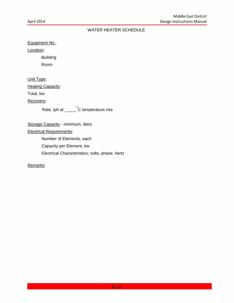
Middle East District April 2014 Design Instructions Manual
WATER HEATER SCHEDULE
Equipment No.:
Location:
Building
Room
Unit Type:
Heating Capacity:
Total, kw
Recovery:
Rate, lph at _____oC temperature rise
Storage Capacity - minimum, liters
Electrical Requirements:
Number of Elements, each
Capacity per Element, kw
Electrical Characteristics; volts, phase, hertz
Remarks:
11-21
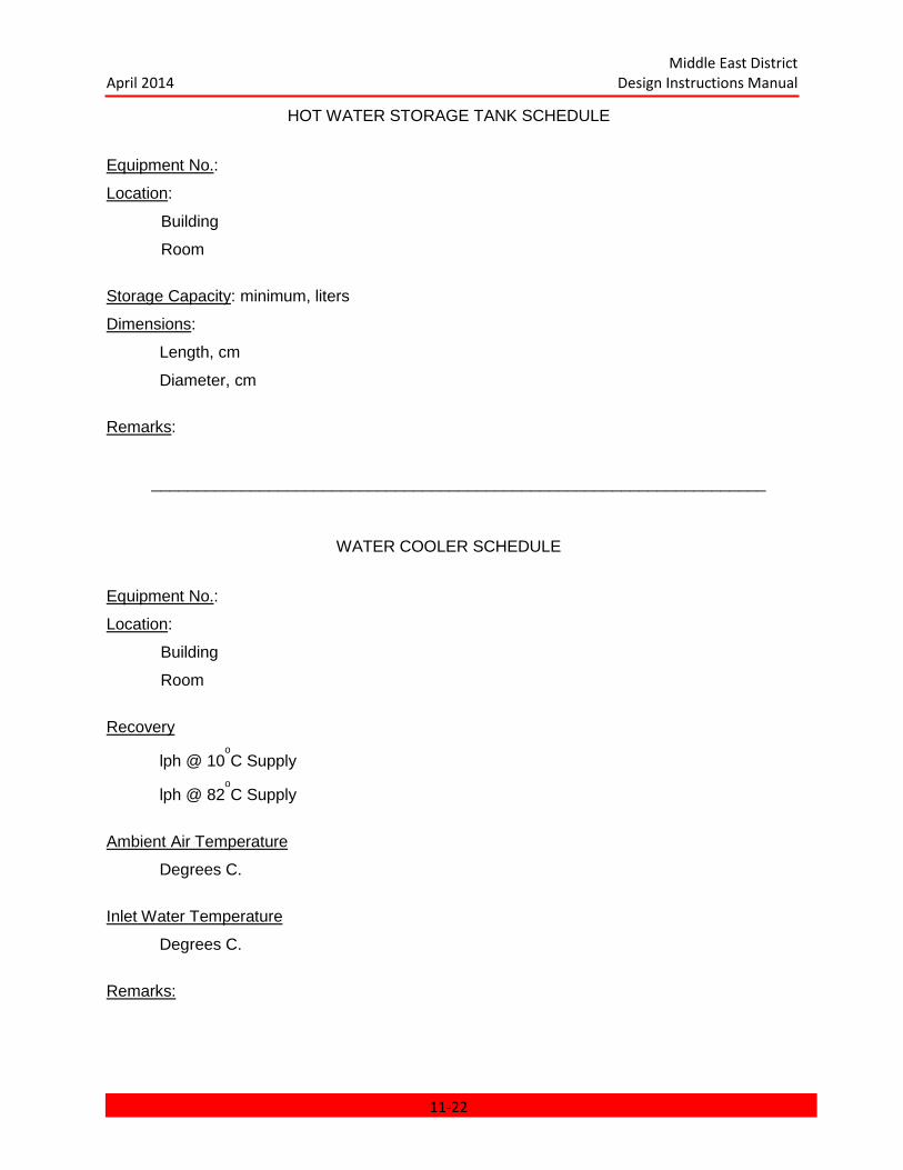
Middle East District April 2014 Design Instructions Manual
HOT WATER STORAGE TANK SCHEDULE
Equipment No.:
Location:
Building
Room
Storage Capacity: minimum, liters
Dimensions:
Length, cm
Diameter, cm
Remarks:
____________________________________________________________________
WATER COOLER SCHEDULE
Equipment No.:
Location:
Building
Room
Recovery
lph @ 10oC Supply
lph @ 82oC Supply
Ambient Air Temperature
Degrees C.
Inlet Water Temperature
Degrees C.
Remarks:
11-22
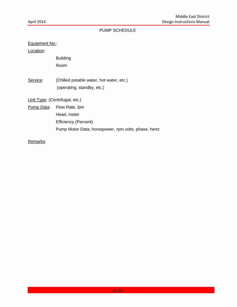
Middle East District April 2014 Design Instructions Manual
PUMP SCHEDULE
Equipment No.:
Location:
Building
Room
Service: (Chilled potable water, hot water, etc.)
(operating, standby, etc.)
Unit Type: (Centrifugal, etc.)
Pump Data: Flow Rate, lpm
Head, meter
Efficiency (Percent)
Pump Motor Data; horsepower, rpm volts, phase, hertz
Remarks:
11-23
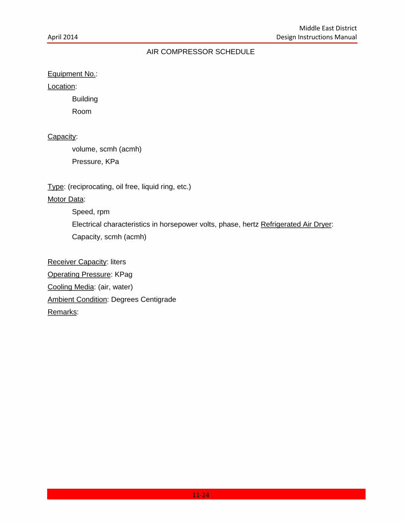
Middle East District April 2014 Design Instructions Manual
AIR COMPRESSOR SCHEDULE
Equipment No.:
Location:
Building
Room
Capacity:
volume, scmh (acmh)
Pressure, KPa
Type: (reciprocating, oil free, liquid ring, etc.)
Motor Data:
Speed, rpm
Electrical characteristics in horsepower volts, phase, hertz Refrigerated Air Dryer:
Capacity, scmh (acmh)
Receiver Capacity: liters
Operating Pressure: KPag
Cooling Media: (air, water)
Ambient Condition: Degrees Centigrade
Remarks:
11-24
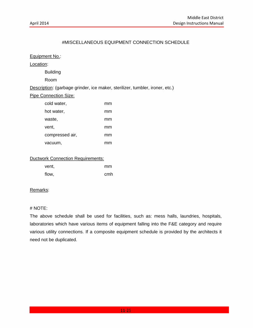
Middle East District April 2014 Design Instructions Manual
#MISCELLANEOUS EQUIPMENT CONNECTION SCHEDULE
Equipment No.:
Location:
Building
Room
Description: (garbage grinder, ice maker, sterilizer, tumbler, ironer, etc.)
Pipe Connection Size:
cold water, mm
hot water, mm
waste, mm
vent, mm
compressed air, mm
vacuum, mm
Ductwork Connection Requirements:
vent, mm
flow, cmh
Remarks:
# NOTE:
The above schedule shall be used for facilities, such as: mess halls, laundries, hospitals,
laboratories which have various items of equipment falling into the F&E category and require
various utility connections. If a composite equipment schedule is provided by the architects it
need not be duplicated.
11-25
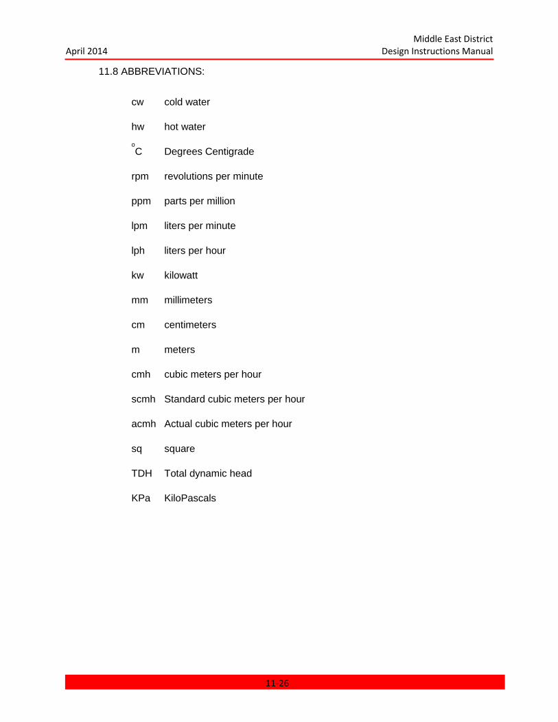
Middle East District April 2014 Design Instructions Manual
11.8 ABBREVIATIONS:
cw cold water
hw hot water oC Degrees Centigrade
rpm revolutions per minute
ppm parts per million
lpm liters per minute
lph liters per hour
kw kilowatt
mm millimeters
cm centimeters
m meters
cmh cubic meters per hour
scmh Standard cubic meters per hour
acmh Actual cubic meters per hour
sq square
TDH Total dynamic head
KPa KiloPascals
11-26
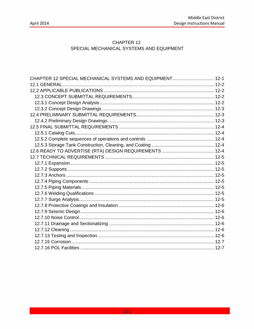
Middle East District April 2014 Design Instructions Manual
CHAPTER 12 SPECIAL MECHANICAL SYSTEMS AND EQUIPMENT
CHAPTER 12 SPECIAL MECHANICAL SYSTEMS AND EQUIPMENT................................ 12-1 12.1 GENERAL ..................................................................................................................... 12-2 12.2 APPLICABLE PUBLICATIONS ..................................................................................... 12-2
12.3 CONCEPT SUBMITTAL REQUIREMENTS ............................................................... 12-2 12.3.1 Concept Design Analysis ........................................................................................ 12-2 12.3.2 Concept Design Drawings ...................................................................................... 12-3
12.4 PRELIMINARY SUBMITTAL REQUIREMENTS ............................................................ 12-3 12.4.2 Preliminary Design Drawings .................................................................................. 12-3
12.5 FINAL SUBMITTAL REQUIREMENTS ......................................................................... 12-4 12.5.1 Catalog Cuts ........................................................................................................... 12-4 12.5.2 Complete sequences of operations and controls .................................................... 12-4 12.5.3 Storage Tank Construction, Cleaning, and Coating ................................................ 12-4
12.6 READY TO ADVERTISE (RTA) DESIGN REQUIREMENTS ........................................ 12-4 12.7 TECHNICAL REQUIREMENTS .................................................................................... 12-5
12.7.1 Expansion ............................................................................................................... 12-5 12.7.2 Supports ................................................................................................................. 12-5 12.7.3 Anchors .................................................................................................................. 12-5 12.7.4 Piping Components ................................................................................................ 12-5 12.7.5 Piping Materials ...................................................................................................... 12-5 12.7.6 Welding Qualifications ............................................................................................ 12-5 12.7.7 Surge Analysis ........................................................................................................ 12-5 12.7.8 Protective Coatings and Insulation .......................................................................... 12-6 12.7.9 Seismic Design ....................................................................................................... 12-6 12.7.10 Noise Control ........................................................................................................ 12-6 12.7.11 Drainage and Sectionalizing ................................................................................. 12-6 12.7.12 Cleaning ............................................................................................................... 12-6 12.7.13 Testing and Inspection .......................................................................................... 12-6 12.7.15 Corrosion .............................................................................................................. 12-7 12.7.16 POL Facilities ....................................................................................................... 12-7
12-1
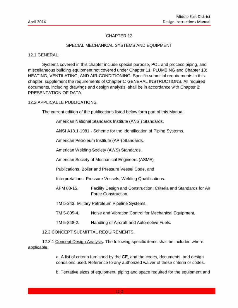
Middle East District April 2014 Design Instructions Manual
CHAPTER 12
SPECIAL MECHANICAL SYSTEMS AND EQUIPMENT
12.1 GENERAL.
Systems covered in this chapter include special purpose, POL and process piping, and miscellaneous building equipment not covered under Chapter 11: PLUMBING and Chapter 10: HEATING, VENTILATING, AND AIR-CONDITIONING. Specific submittal requirements in this chapter, supplement the requirements of Chapter 1: GENERAL INSTRUCTIONS. All required documents, including drawings and design analysis, shall be in accordance with Chapter 2: PRESENTATION OF DATA.
12.2 APPLICABLE PUBLICATIONS.
The current edition of the publications listed below form part of this Manual.
American National Standards Institute (ANSI) Standards.
ANSI A13.1-1981 - Scheme for the Identification of Piping Systems.
American Petroleum Institute (API) Standards.
American Welding Society (AWS) Standards.
American Society of Mechanical Engineers (ASME)
Publications, Boiler and Pressure Vessel Code, and
Interpretations: Pressure Vessels, Welding Qualifications.
AFM 88-15. Facility Design and Construction: Criteria and Standards for Air Force Construction.
TM 5-343. Military Petroleum Pipeline Systems.
TM 5-805-4. Noise and Vibration Control for Mechanical Equipment.
TM 5-848-2. Handling of Aircraft and Automotive Fuels.
12.3 CONCEPT SUBMITTAL REQUIREMENTS.
12.3.1 Concept Design Analysis. The following specific items shall be included where applicable.
a. A list of criteria furnished by the CE, and the codes, documents, and design conditions used. Reference to any authorized waiver of these criteria or codes.
b. Tentative sizes of equipment, piping and space required for the equipment and
12-2
Middle East District April 2014 Design Instructions Manual
distribution method selected.
c. A description of the proposed control system.
d. Description, approximate capacity, and location of any miscellaneous equipment such as elevators, cranes, lifts, etc.
e. Description of the various types and quantities (supported by calculations as applicable) of POL products and their associated unloading, storage, and dispensing systems.
12.3.2 Concept Design Drawings. The following specific items shall be shown where applicable.
a. Flow diagrams of all systems proposed. These diagrams shall be an accurate schematic representation of the system, showing all proposed equipment, piping, control valves and primary control loops. In addition, the drawings shall indicate approximate capacities of equipment; flow rates in mains, branches, and outlets; and shall identify the location of equipment by building and room.
b. Plans which are sufficiently complete to show the location and general arrangement of mechanical equipment and major piping. Piping may be shown with single lines.
12.4 PRELIMINARY SUBMITTAL REQUIREMENTS.
12.4.1 Preliminary Design Analysis. The Preliminary design analysis shall include all items in the Concept design analysis and any necessary revisions. In addition, the following specific items shall be included when applicable.
a. Detailed calculations for sizing equipment, storage tanks, filter pumps, piping, control valves, liquid surge analysis, etc.
b. Detailed logic diagrams for the control schemes used.
c. Any other information or computation required to verify that the design complies with the design criteria, codes, and standards, and is satisfactory for the intended purpose.
d. Catalog Cuts. Minimum catalog cuts shall be submitted for all major items of equipment. Catalog cuts shall be a part of the design analysis.
12.4.2 Preliminary Design Drawings. The following specific items shall be shown when applicable.
12.4.2.1 Flow Diagrams of All Systems. These diagrams shall show all of the information given on the Concept drawings, but in greater detail. The diagrams shall include equipment capacities and power requirements, all piping sizes with flow rates indicated, all valves, piping specialties, instrumentation, and control devices.
12-3
Middle East District April 2014 Design Instructions Manual
12.4.2.2 Plans showing layout and details of the final version of the proposed system, showing location, arrangement, capacity, and space requirements of all equipment.
12.4.2.3 Equipment. The drawings shall include space for rating data in tabular form for all items of equipment, with space reserved for designating the manufacturer and the model number in anticipation of as-built drawings. Preliminary rating data shall be submitted for all items of equipment, even though it is not mandatory that it be inserted in the equipment schedule at this stage. Equipment schedules shall be completed when final rating data are established, but not later than the Final submission. Since equipment rooms represent the most congested areas for both equipment and piping, the following guidelines should be followed when drawings are being prepared.
a. Single-line piping or ducting layouts are not sufficient to adequately plan major installations and check interference.
b. All pipe shall be shown by single-line layouts and symbols except in equipment rooms or other congested areas to assure that the allocated space is adequate for installation, maintenance or repair work. Pipes 3 inches and larger shall be shown to scale by double-line layout.
c. All ducts and fittings in equipment rooms and other related congested areas shall be drawn to scale by double-line layouts.
d. All equipment shall be outlined to scale, and maintenance or removal space shall be indicated.
e. Removal, replacement, or moving space must be considered for the largest and heaviest equipment when a drawing is made.
f. In plans, sections, and details these same rules shall apply.
12.5 FINAL SUBMITTAL REQUIREMENTS.
The design analysis and the drawings submitted for the Final review shall be complete, as described in Chapter 1: GENERAL INSTRUCTIONS.
12.5.1 Catalog Cuts. Complete catalog cuts and data sheets shall be submitted for all major items of equipment. Catalog cuts shall be a part of the design analysis.
12.5.2 Complete sequences of operations and controls.
12.5.3 Storage Tank Construction, Cleaning, and Coating.
A complete analysis shall be submitted indicating the type and degree of cleaning required, and tank coatings to be utilized.
12.6 READY TO ADVERTISE (RTA) DESIGN REQUIREMENTS.
The comments generated during the Final design review shall be incorporated in
12-4
Middle East District April 2014 Design Instructions Manual
the documents before they are submitted as Ready To Advertise (RTA).
12.7 TECHNICAL REQUIREMENTS.
12.7.1 Expansion.
12.7.1.1 Temperature Ranges. When designing the flexibility of the system, full consideration shall be given to the maximum and minimum temperature to which the line will be exposed. This shall include not only environmental temperatures but also temperatures of cleaning processes such as steam or vapor. Ample provision shall be made for temperature ranges and shall be completely covered by the design analysis. Generally, where expansion of piping will be absorbed by utilizing the inherent flexibility of the piping or by providing expansion loops and bends, the pipe expansion stresses shall be calculated by a standard method used in industry such as the Tube Turn, Blaw-Knox, Grinnell, or M. W. Kellogg methods.
12.7.1.2 Piping Alignment. The horizontal and vertical alignment of the piping shall be carefully planned to utilize the inherent flexibility of the pipe to absorb expansion. Obstructions such as road crossings which may occur in the route of the piping shall be given due consideration.
12.7.2 Supports. Supports for aboveground piping shall be designed with full allowances for the movement and forces developed by the piping, either during operation, testing, cleaning, or shock loading, whichever is the most severe condition, and shall be of ample strength to withstand the forces developed by the piping.
12.7.3 Anchors. All pipe anchors shall be designed to completely withstand the maximum forces developed by the pipe system during the most severe condition of operation, either during regular operation, testing, shock loading, or cleaning. Design calculations for anchors shall be a part of the design analysis and should show all forces, assumptions, soil bearing values, etc.
12.7.4 Piping Components. Components such as valves, strainers, gages, surge suppressors, and other devices shall be specified in detail with pressure or temperature rating, size, capacity, pressure and temperature ranges, test pressures, and materials called out. Valves and miscellaneous components shall be as directed by Middle East District (MED) or applicable publications.
12.7.5 Piping Materials. The options on materials for the piping systems shall be furnished as part of the design criteria. Pipe and tank coatings shall be as directed by Middle East District or the applicable publications.
12.7.6 Welding Qualifications. Welding shall be specified in accordance with the ASME Boiler and Pressure Vessel Code, ANSI Piping Code, or the American Welding Society Standards. Requirements for welding procedure, welding operator, and welder qualification and identification shall be specified. Detailed requirements for welding shall be specified.
12.7.7 Surge Analysis. A complete fuel surge analysis shall be performed upon the
12-5

Middle East District April 2014 Design Instructions Manual
final design of the fuel systems. All corrective action to the design shall be performed as required. The surge shall be less than the pressure ratings of all system components.
12.7.8 Protective Coatings and Insulation. Protective coating for both aboveground and underground piping shall be specified with appropriate test procedures.
12.7.9 Seismic Design. Design shall conform to the requirements of the Seismic Zone.
12.7.10 Noise Control. All design work shall be in accordance with TM 5-805-4.
12.7.11 Drainage and Sectionalizing. All conditions of operation of the system shall be taken into consideration when designing the drainage points and sectionalizing. If a system is to be cleaned in place, the line shall be capable of being divided into short sections for ease of cleaning without having to cut the piping. Drains shall be located at all low points, and if they are to be used for cleaning or flushing, they will be of a size large enough to assure adequate flow of cleaning agents and rinses. Piping systems shall contain sufficient isolation valves to allow segregation of the system for maintenance and/or testing. Piping distribution systems, which may be extended by another contractor or at some future date, shall be terminated with blind-flanged valved connections.
12.7.12 Cleaning. The details of the cleaning processes
and the number and location of cleanings shall be specified. The specification shall call out the degree of inspection and shall require the use of approved cleaning facilities. Detailed cleaning procedures shall be required of the Contractor prior to cleaning any piping. Shop cleaned pipe or components cleaned off the job will be required to be sealed against contamination with a substantial sealing method which will endure, without failure, the rigors of shipment, handling, and storage.
12.7.13 Testing and Inspection.
12.7.13.1 General Requirements. Methods and degree of cleanliness and welding inspection shall be specified. Generally, welding inspections shall consist of visual and radiographic or other non-destructive inspection. The method of testing and the standards by which they will be judged shall be indicated.
12.7.13.2 Detailed Requirements shall be specified for pressure, leak, and operational testing. All test requirements for components such as leak testing and proof testing shall be specified in detail. Operational tests shall also be carefully indicated. Records of all tests shall be made and reproducible copies shall be turned over to the Contracting Officer. Performance and other tests of valves, strainers, etc., shall require certification, with copies furnished to the Contracting Officer.
12.7.14 Piping Identification. Piping systems in boiler plants, heating plants, buildings, mechanical equipment rooms, and tunnels will be identified in accordance with the applicable portion of the American National Standard Institute (ANSI) A13.1. Bulk petroleum
12-6

Middle East District April 2014 Design Instructions Manual
product systems and Compressed gas cylinders and piping shall be coded in accordance with accepted Commercial and Industry Standards. Special markings or identification may be required, and will be as directed by MED.
12.7.15 Corrosion. For corrosion protection, see paragraph: Corrosion in Chapter 11. Special corrosion protection will be required for underground piping based on project location, as directed by Transatlantic Division.
12.7.16 POL Facilities. POL facilities shall be in accordance with TM 5-343, TM 5-800-1, TM 5-848-2, and AFM 88-15.
12-7

Middle East District April 2014 Design Instructions Manual
CHAPTER 13 SAFETY
CHAPTER 13 SAFETY ......................................................................................................... 13-1 13.1 GENERAL ..................................................................................................................... 13-2
13.1.1 Policy ...................................................................................................................... 13-2 13.1.2 Criteria .................................................................................................................... 13-2 13.1.3 Scope ..................................................................................................................... 13-2 13.1.4 Reviews .................................................................................................................. 13-2 13.1.5 Built-in Safety ......................................................................................................... 13-2 13.1.6 Interpretations ......................................................................................................... 13-2 13.1.7 Document Requirements ........................................................................................ 13-2
13.2 APPLICABLE PUBLICATIONS ..................................................................................... 13-3 13.3 CONCEPT SUBMITTAL REQUIREMENTS .................................................................. 13-3
13.3.1 Concept Design Analysis ........................................................................................ 13-3 13.3.2 Concept Design Drawings ...................................................................................... 13-4
13.4 PRELIMINARY SUBMITTAL REQUIREMENTS ............................................................ 13-5 13.4.1 Preliminary Design Analysis ................................................................................... 13-5 13.4.2 Preliminary Design Drawings .................................................................................. 13-5
13.5 FINAL SUBMITTAL REQUIREMENTS ......................................................................... 13-5 13.6 READY TO ADVERTISE (RTA) DESIGN REQUIREMENTS ........................................ 13-6 13.7 TECHNICAL REQUIREMENTS .................................................................................... 13-6
13.7.1 Human Engineering ................................................................................................ 13-6 13.7.2 Explosive Safety ..................................................................................................... 13-7 13.7.3 Hazardous Materials ............................................................................................... 13-7 13.7.4 Noise ...................................................................................................................... 13-7 13.7.5 Facility Security ...................................................................................................... 13-7 13.7.6 Protective Construction ........................................................................................... 13-7
13-1
Middle East District April 2014 Design Instructions Manual
CHAPTER 13
SAFETY
13.1 GENERAL.
13.1.1 Policy. The design of facilities, equipment, and systems shall provide a safe and healthful work environment such that occupants, and operations and maintenance personnel suffer no avoidable risk in the performance of their respective work, thereby preserving the safety of personnel and property.
13.1.2 Criteria. The nature and mission of these facilities, as well as the impacted time and cost factors, require the following.
a. Safety considerations shall be totally integrated during project development and not imposed upon the final design.
b. Variances with explosive safety requirements shall be avoided.
c. Building codes, safety codes, standards, and requirements shall be uniformly interpreted and applied.
13.1.3 Scope. Explosives, systems, and industrial safety; fire protection; industrial hygiene; and human engineering shall be fully considered in the development and design of projects.
13.1.4 Reviews. All designs shall be reviewed prior to their approval for conformance with established safety codes, standards, and principles and with regard to accident prevention principles. Planning and design personnel shall apply the same analytical approach to identifying potential hazards and incorporating appropriate safeguards that they apply to other design problems.
13.1.5 Built-in Safety. Equipment, systems, and facilities shall be designed so that hazards are eliminated. Where the lack of technology or the constraints of operational effectiveness preclude this, appropriate measures shall be built-in to identify and control hazardous conditions or otherwise safeguard personnel and property. Intrinsic safety and fail-safe devices shall be used to the maximum rather than depending on less reliable means.
13.1.6 Interpretations. Architect-Engineer (A-E) firms and each design element of the Corps of Engineers (CE) shall monitor and control the application of building codes, safety codes, standards, policies, and procedures to assure that they are consistently, uniformly, and effectively applied on all project.
13.1.7 Document Requirements. Specific submittal requirements in this chapter supplement the requirements of Chapter 1: GENERAL INSTRUCTIONS. All required documents, including Drawings and Design Analysis, shall be in accordance
13-2

Middle East District April 2014 Design Instructions Manual
with Chapter 2: PRESENTATION OF DATA.
13.2 APPLICABLE PUBLICATIONS.
The following publications of the issues listed below, but referred to thereafter by basic designation only, form a part of this manual to the extent indicated by the references thereto:
MIL-STD-882D Military Standard Practice for System Safety
UFC 4-010-01 Minimum Antiterrorism Standards for Buildings
AR 385-63. Policies and Procedures for Firing Ammunition for Training, Target Practice and Combat.
AR 385-64. Ammunition and Explosive Safety Standards.
UFC 3-340-01 Design and Analysis of Hardened Structures to Conventional Weapons Effects.
UFC 3-340-02 Structures to Resist the Effects of Accedental Explosions.
TB Med 501. Noise and Conservation of Hearing, Aug 88.
13.3 CONCEPT SUBMITTAL REQUIREMENTS.
13.3.1 Concept Design Analysis. The following specific items shall be included when applicable.
13.3.1.1 Siting. Special considerations shall be given to the design and location of facilities that involve the handling, manufacture, storage, and transportation of hazardous materials, such as ammunition, explosives, chemicals, and liquid propellants. Site planning for such facilities should be done as soon as the requirement is known. All facilities shall be sited in accordance with the requirements of AR 385-63, and AR 385-64.
13.3.1.2 Safety. Analyze the project in terms of the required criteria and determine the following.
a. The types of hazardous materials to be used or stored in the facility or to be used in its construction and the general methods to be incorporated in order to maintain the required standards of safety.
b. The type of electrical equipment and light fixtures, ventilation requirements, and other related safety features required for any buildings or areas involved with the use or storage of hazardous materials.
c. The guidelines to be used to control noise levels throughout the project.
13-3

Middle East District April 2014 Design Instructions Manual
13.3.1.3 Security.
a. List all facilities and/or rooms that are to be secure against theft, or sabotage and the recommended means by which the security is to be achieved. Rooms or areas wherein arms, ammunition, high value items, narcotics, classified documents, are stored as well as mission critical rooms or areas such as power plants, communication centers, command posts will require varying degrees of security. Fully describe rationale used in recommending each security measure. All design discipline applicable to the security measures shall provide a narrative description of the means and degree by which the security measure accomplishes its task.
b. The duration of the "button-up" period and the necessity for standby electrical and mechanical systems.
13.3.2 Concept Design Drawings. The following specific items shall be shown when applicable.
13.3.2.1 Site Safety Plan. Prepare a site plan to present a compendium of the total explosives safety features being incorporated into the site layout. As a minimum, such plans shall contain the following data.
a. The location and distances between the facility to be constructed or modified and other installation facilities, the installation boundary, public railways and public highways, including power transmission and utility lines.
b. The identification and brief description of the mission of all other facilities which will be constructed or modified within the inhabited building distance of the facility.
c. A general description of items, components, or other hazardous materials to be handled or stored in the new or modified facility; i.e., rockets, artillery ammunition, fuses, etc.
d. The explosive limits and class(es) of ammunition, explosives, or other hazardous materials proposed for the facility, including a breakdown by room or bay when appropriate.
e. The explosive limits and class(es) of ammunition, explosives, or other hazardous materials in facilities located within the inhabited building distance of the facility.
f. A topographic map with appropriate contours when terrain features are considered to constitute natural barricading or when topography otherwise influences layout.
13-4

Middle East District April 2014 Design Instructions Manual
13.3.2.2 Other Drawings. In general, very little detail beyond the Fire Protection Plan is required for the Concept design submittal. However, if any unusual pieces of equipment or methods of protection are proposed, details shall be shown on the appropriate drawings.
13.4 PRELIMINARY SUBMITTAL REQUIREMENTS.
13.4.1 Preliminary Design Analysis. The preliminary design analysis shall include all items in the concept design analysis and any necessary revisions. In addition, the following specific items shall be included when applicable.
13.4.1.1 Safety. The following items shall be included in the Preliminary design analysis.
a. A comprehensive analysis of all safety requirements of a facility with an indication of the treatment for each potential hazard, the alternatives considered, and the justification for the alternatives selected.
b. Calculations for the following items.
1. Noise control.
2. Ventilation requirements.
3. Explosion protection.
c. A complete list of materials used in construction that may be of a hazardous nature and the precautions, protection equipment, or treatment required due to the use of these materials.
13.4.1.2 Facility Security. Include in the Preliminary design analysis a comprehensive analysis of all security measures taken for a facility with an indication of the security measures employed, the alternatives considered, and the justification for the alternatives selected.
13.4.1.3 Protective Construction. Include a comprehensive analysis of the protective construction measures for a facility with an indication of the protective measures taken, the alternatives considered, and the justification for the alternatives selected. Calculations for any structural protective construction measures shall appear with the other structural calculations.
13.4.2 Preliminary Design Drawings. Many of the features for safety, physical security, and protective construction shall appear on the drawings of the various disciplines. In addition, the following specific item shall be shown on a separate drawing.
13.4.2.1 Site Safety Plan. Submit the revised compendium of the total explosive safety features previously submitted with the Concept design drawings.
13.5 FINAL SUBMITTAL REQUIREMENTS.
13-5
Middle East District April 2014 Design Instructions Manual
The design analysis shall include all the items in the Preliminary design analysis and any necessary revisions. For mechanical items such as pumps and blowers, provide a list of at least three manufacturers whose equipment will perform the desired function. The design analysis and the drawings submitted for Final review shall be complete, as described in Chapter 1: GENERAL INSTRUCTIONS.
13.6 READY TO ADVERTISE (RTA) DESIGN REQUIREMENTS.
The comments generated during the Final design review shall be incorporated into the documents before they are submitted as READY TO ADVERTISE (RTA).
13.7 TECHNICAL REQUIREMENTS.
13.7.1 Human Engineering. To be safe as well as usable, facilities, equipment, and operations must be adapted to the limitations of the people who use them. In keeping with this, designs and specifications shall consider the following items.
a. When equipment is inappropriate or inadequate, people will improvise and modify, thereby taking unnecessary risks and exposure to hazards and accidents.
b. Reliance shall not be placed on the safety consciousness of personnel where it is feasible to provide protection against human error.
c. Anticipate that equipment may be used improperly and procedures improvised, and then design the operation to minimize the consequences.
d. Make sure that equipment use and limits are readily identifiable to help assure that it will be operated and maintained properly.
e. A warning note in technical and operating manuals will not overcome a safety problem. People may not read, remember, or even know where to find the warning notes. Bilingual warning signs shall be placed near hazardous operations areas.
f. Do not assume that effective standard operating procedures will be developed or that personnel will receive appropriate safety indoctrination, training, and supervision. Instead, build safety into the design.
13.7.1.1 Accessibility Check. Designers shall check each system and its equipment to assure ready accessibility and operability of all maintenance points, gages, valves, controls, and signals. Devices whose operations are critical during emergency conditions shall be prominently located and singularly identified.
13.7.1.2 Coordination Check. A cross-check shall be made by designers of the structural, process piping, heating and ventilation, plumbing, conveyors, and packaged
13-6

Middle East District April 2014 Design Instructions Manual
equipment and systems in order to detect and correct interferences with illumination levels, fire detection, alarm and suppression systems, toxic or explosive detection systems, personnel, fire doors and shutters and material and equipment traffic or other degradations of the safety of personnel or property.
13.7.2 Explosive Safety. AR 385-64 is the standard for explosive safety. Its provisions shall be fully incorporated in the design of explosives related facilities. TM 5-1300 shall be used to locate and design barricades, blast walls, and other blast-resistive structures.
13.7.3 Hazardous Materials. Chemicals are used throughout industry as preservatives for equipment in storage, as equipment lubricants and cleaners, as electrical conducting or insulating mediums, and as sealants or protective coatings for working surfaces. However, many of these compounds are also flammable, toxic, or allergenic in nature. The danger to personnel and property rise steadily in light of the annual introduction of new chemicals and the use of trade names which do not identify the product's chemical constituents. In selecting generic or trade name chemicals to be called for in the specifications, A-E's must investigate the flammability, toxicity, and allergenic hazards associated with those chemicals. To the maximum extent possible, those chemicals which are considered nonhazardous shall be specified. Where chemicals of a hazardous nature are employed for lack of a safe substitute, the construction specification paragraph shall identify the hazards, the precautions, personal protective equipment or apparel, first-aid treatment, antidote, and fire fighting equipment to be employed. Technical sections of specifications containing epoxy coatings and/or mortar shall include a paragraph on safety precautions. Film projection rooms shall be designed for the hazards associated with the use of cellulose base film.
13.7.4 Noise. Technical specifications for mechanical and electrical equipment shall be developed to call for noise levels in inhibited equipment spaces that are consistent with the levels set forth in TB Med 501, entitled "Noise and Conservation of Hearing". Consistent with these requirements, designers shall provide an engineering estimate of sound pressure levels for mechanical-electrical equipment for use in the design of the structure.
13.7.5 Facility Security. There are no additional requirements for facility security systems. Refer to the criteria previously listed and to Chapter 17: COMMUNICATIONS and Chapter 14: ELECTRICAL.
13.7.6 Protective Construction. There are no additional requirements for protective construction designs. Refer to the criteria previously listed and to Chapter 8: STRUCTURAL.
13-7

Middle East District April 2014 Design Instructions Manual
CHAPTER 14
ELECTRICAL
CHAPTER 14 ELECTRICAL ................................................................................................. 14-1 14.1 GENERAL ..................................................................................................................... 14-3
14.1.1 Application .............................................................................................................. 14-3 14.2 APPLICABLE PUBLICATIONS ..................................................................................... 14-3
14.2.1 Additional Standards ............................................................................................... 14-5 14.3 CONCEPT SUBMITTAL REQUIREMENTS .................................................................. 14-5
14.3.1 Concept Design Analysis ........................................................................................ 14-5 14.3.2 Concept Design Drawings .................................................................................... 14-10 14.3.3 Concept Design Specifications ............................................................................. 14-12
14.4 PRELIMINARY SUBMITTAL REQUIREMENTS .......................................................... 14-12 14.4.1 Preliminary Design Analysis ................................................................................. 14-12 14.4.2 Preliminary Design Drawings ................................................................................ 14-14 14.4.3 Preliminary Design Specifications ......................................................................... 14-15
14.5 FINAL SUBMITTAL REQUIREMENTS ....................................................................... 14-15 14.5.1 Final Design Analysis ........................................................................................... 14-15 14.5.2 Final Design Drawings .......................................................................................... 14-18 14.5.3 Final Design Specifications ................................................................................... 14-19
14.6 READY TO ADVERTISE (RTA) DESIGN REQUIREMENTS ...................................... 14-19 14.6.1 RTA Design Analysis ............................................................................................ 14-19 14.6.2 RTA Design Drawings .......................................................................................... 14-19 14.6.3 RTA Design Specifications. .................................................................................. 14-20
14.7 TECHNICAL REQUIREMENTS .................................................................................. 14-20 14.7.1 General Requirements .......................................................................................... 14-20 14.7.2 Equipment ............................................................................................................ 14-20 14.7.3 Services ................................................................................................................ 14-20 14.7.4 Metering ............................................................................................................... 14-20 14.7.5 Power Utilization Voltage Levels ........................................................................... 14-20 14.7.6 Transformers ........................................................................................................ 14-21 14.7.7 Branch Circuits ..................................................................................................... 14-21 14.7.8 Feeders and Sub-Feeders .................................................................................... 14-22 14.7.9 Wiring Methods and Materials .............................................................................. 14-22 14.7.10 Panelboards ....................................................................................................... 14-23 14.7.11 Lighting ............................................................................................................... 14-24 14.7.12 Control Circuits ................................................................................................... 14-27 14.7.13 Fire Alarm System .............................................................................................. 14-28 14.7.14 Hazardous Locations .......................................................................................... 14-28 14.7.15 Grounding ........................................................................................................... 14-28 14.7.15.1 Grounding system ............................................................................................ 14-28 14.7.16 Substations ......................................................................................................... 14-28
14-1

Middle East District April 2014 Design Instructions Manual
14.7.17 Switchboards ...................................................................................................... 14-28 17.7.18 Motors and Controllers ....................................................................................... 14-29 14.7.19 Security Control Systems .................................................................................... 14-29 14.7.20 Units of Measure................................................................................................. 14-29
EXAMPLE 1 - Panelboard Schedule ................................................................................... 14-32 EXAMPLE 2 - Lighting Fixture Schedule ............................................................................. 14-33
14-2

Middle East District April 2014 Design Instructions Manual
CHAPTER 14
ELECTRICAL
14.1 GENERAL 14.1.1 Application. This chapter gives requirements for the preparation of drawings,
specifications, and design analysis of electrical systems. Electrical systems include distribution systems, lighting systems, fire detection and alarm systems, and security alarm systems.
Specific requirements for related electrical design are found in Chapter 15: POWER GENERATION, Chapter 16: POWER TRANSMISSION AND DISTRIBUTION, and Chapter 17: COMMUNICATIONS.
The requirements of this chapter supplement the requirements in Chapter 1: GENERAL INSTRUCTIONS, Chapter 2: PRESENTATION OF DATA, Chapter 3: SPECIFICATIONS, and Chapter 4: COST ESTIMATING. In addition, the electrical design requirements must be coordinated with the requirements of Chapter 9: FIRE PROTECTION AND LIFE SAFETY, and Chapter 10: HEATING, VENTILATING, AND AIR CONDITIONING, and Chapter 12: SPECIAL MECHANICAL SYSTEMS AND EQUIPMENT, and Chapter 13: SAFETY.
14.2 APPLICABLE PUBLICATIONS.
The current editions of the publications listed below form a part of this manual and define the standard to which the electrical design shall conform.
Corps of Engineers Computer-Aided Design and Drafting (CADD) Details:
Standard Details Internet Hyperlink https://cadbim.usace.army.mil/default.aspx?p=s&t=13&i=17
United Facilities Criteria (UFC):
UFC 3-501-01 Electrical Engineering
UFC 3-510-01 Foreign Voltages and Frequencies Guide
UFC 3-520-01 Interior Electrical Systems
UFC 3-530-01 Design: Interior and Exterior Lighting and Controls
UFC 3-535-01 Visual Air Navigation Facilities
UFC 3-540-04N Diesel Electric Generating Plants
UFC 3-550-01 Exterior Electrical Systems
14-3

Middle East District April 2014 Design Instructions Manual
UFC 3-555-01N 400 Hertz Medium Voltage Conversion/Distribution and Low Voltage Utilization Systems
UFC 3-570-02A Cathodic Protection
UFC 3-580-01 Telecommunications Building Cabling Systems Planning and Design
UFC 3-600-01 Fire Protection Engineering for Facilities
UFC 4-020-04A Electronic Security Systems: Security Engineering
UFC 4-021-01 Design and O&M: Mass Notification Systems
UFC 4-121-10 Design: Aircraft Fixed Point utility Systems
UFC 4-510-01 Design: Medical Military Facilities
Department of the Navy
Naval Facilities Engineering Command:
MIL-HDBK-419A Grounding, Bonding and Shielding for Electronic Equipment and Facilities.
MIL-HDBK-1004/1 Electrical Engineering Preliminary Design Considerations.
MIL-HDBK-1004/6 Electrical Engineering Lightning Protection Systems.
MIL-HDBK-1O12/1 Electronic Facilities Engineering.
Illuminating Engineering Society (IES):
IES Lighting Handbook - Application Volume
IES Lighting Handbook - Reference Volume
Institute of Electrical and Electronic Engineers (IEEE):
IEEE Std. 141 IEEE Recommended Practice for Electrical Power Distribution for Industrial Plants. (Red Book)
IEEE Std. 142 IEEE Recommended Practice for Grounding of Industrial and Commercial Power Systems. (Green Book)
IEEE Std. 241 IEEE Recommended Practice for Electrical Power Systems in Commercial Buildings. (Gray Book)
14-4
Middle East District April 2014 Design Instructions Manual
IEEE Std. 242 IEEE Recommended Practice for Protection and Coordination of Industrial and Commercial Power Systems. (Buff Book)
IEEE Std. 399 IEEE Recommended Practice for Power Systems Analysis. (Brown Book).
IEEE Std. 446 IEEE Recommended Practice for Emergency and Standby Power Systems.(Orange Book)
IEEE Std. 493 IEEE Recommended Practice for Design of Reliable Industrial and Commercial Power Systems. (Gold Book)
IEEE Std. 602 Recommended Practice for Electric Systems in Health Care Facilities (White Book)
IEEE Std. 739 Recommended Practice for Energy Conservation and Cost-Effective Planning in Industrial Facilities (Bronze Book)
IEEE Std. 1100 Powering and grounding Sensitive Electronic Equipment (Emerald Book)
C2 National Electrical Safety Code
National Fire Protection Association (NFPA):
NFPA 70 National Electrical Code (NEC).
NFPA 101 Life Safety Code.
Pamphlet 72 Fire Alarm Signalling Systems.
14.2.1 Additional Standards. In addition to the above standards, there may be design standards which are enforced by the government of the country in which the project is located. These standards, if any, are identified in the Scope of Work. Conflicts between standards shall be brought to the Government's attention for resolution.
14.3 CONCEPT SUBMITTAL REQUIREMENTS.
The concept submittal shall provide sufficient information to show how the functional requirements of the electrical design will be met. The specific information required to achieve this is provided in the following sections.
14.3.1 Concept Design Analysis. The concept design analysis shall provide narrative descriptions, initial calculations, analysis of alternative design approaches, and
14-5

Middle East District April 2014 Design Instructions Manual
recommendations which explain and justify the concept design presented. The design analysis shall also document how design criteria has been met. The following items shall be included in the concept design analysis. (Note: Items that are not applicable to the project shall be noted as such in the design analysis.) The design analysis shall consist of two parts, part A: Narrative, and part B: Calculations. The calculations may be provided as an appendix to the narrative.
NARRATIVE:
14.3.1.1 Site Electrical Supply and Distribution
a. Service Availability: Discuss the availability of electrical service from the local utility, on-site electrical distribution system, or local generator.
1. Summarize calculations (provided as an appendix to the design analysis) of the estimated project load, including any assumptions and approximations made (follow applicable procedures of UFC 3-501-01 or MIL-HDBK-1004/1)
2. Identify the recommended source of power and discuss its capacity to meet the estimated demand of the new load.
3. Define the characteristics of the power source at the point of service to the new facility, i.e. voltage, frequency, number of phases, KVA capacity, and available fault current. Discuss all assumptions made.
b. Distribution Scheme: Describe the proposed distribution scheme. Provide reasoning for selection of simple radial, loop radial, primary selective, etc. system. The description shall also include an explanation of the protection scheme proposed for the distribution scheme (with appropriate references to the site one line diagram). The recommended distribution system shall be responsive to the operational needs of the facility as well as economic factors. The description should include a discussion of the recommended distribution voltage levels and location of transformers. Computer or manual calculations of approximate short circuit current and voltage drop associated with the proposed scheme (for major components only, to demonstrate the range of expected results) shall be provided (in the appendix) and the results discussed in the narrative.
c. Grounding: Describe the proposed grounding scheme (i.e., resistance or solidly grounded distribution systems, lightning protection grounds, special equipment grounds, etc). Indicate how the grounds will be interconnected within the site, including the use of counterpoise conductors, building ground rings, ground rods, etc.
d. Construction Methods: Describe the proposed construction method (direct burial, duct bank, aerial) and provide supporting documentation for the recommended approach. Both operational requirements (reliability, site congestion, etc.) and cost shall be addressed in the analysis. Design criteria, such as separation of medium voltage (15KV), high voltage (33KV etc), low voltage (380V), and signal conductors
14-6

Middle East District April 2014 Design Instructions Manual
shall be discussed.
14.3.1.2 Other Electrical Site Utilities.
a. Telephone/Data: Describe the site telephone/data system requirements. Identify project requirements (such as number of trunk lines) and requirements for connection with supplying telephone service (such as transmission protocol, 2 or 4 wire circuit, twisted pair, single-mode, multi-mode fiber, etc.). Identify source of telephone service. Describe proposed construction method for installation of interconnecting cables. Define proposed responsibilities (i.e. does the contractor or the user provide the cable, who makes what connections, etc.). Requirements of UFC 3-580-01 shall be followed.
b. Fire Alarm: Describe the site fire alarm system requirements. Identify requirements for project alarm, site alarm system, and proposed method of interconnection. Identify proposed construction method or signaling technology. Define proposed responsibilities between the contractor and the local fire authority.
c. Security: Describe the requirements for any site security systems (i.e. CCTV, intrusion detection, etc.) identified in the Scope of Work. For each required system, describe the proposed technology (i.e., infrared, capacitance field, tensioned wire, microwave, etc.) construction methods (coax, fiber optic, radio, etc.), and routing. This description shall discuss the relative advantages of alternative solutions and provide supporting information for the selected system. Describe proposed interfaces of responsibility between contractor and site security authority.
d. Other: Provide similar analysis for any other site utility identified by the Scope of Work, such as cable TV, data communication, etc.
e. Exterior Lighting: Describe the site lighting requirements, including security lighting. State the proposed lighting intensities for each system. Describe the type of lamps and luminaries for each system, addressing such issues as restoration of lighting after a power outage and color rendition. Describe the proposed spacing and location of such fixtures and their relation to security and maintained uniformity in lighting intensities. Describe the proposed construction method for the wiring and the source of power (including control philosophy).
f. Cathodic Protection: Discuss the requirement (or lack of) for cathodic protection of underground materials. The discussion should address the corrosiveness of the soils, the materials to be used on the project (for all disciplines, not just electrical), and the need for active or passive protection. If protection is required, provide supporting documentation for the recommended system. Be sure to coordinate any special requirements with other design disciplines.
g. Lightning Protection: Identify requirements for lightning protection of any facility included in the project. The discussion should include descriptions of surge arresters for distribution equipment and feeders as well as lightning rods for facilities, down
14-7

Middle East District April 2014 Design Instructions Manual
conductors, and connection to the ground system.
14.3.1.3 Building Electrical Systems
a. Power Distribution: State the proposed system voltage for each level of distribution. Describe how the power will be derived and distributed, including the point of service from the site distribution system. Identify any special utilization requirements (such as 400 HZ power, 120 v power on a 380/220V system, UPS, Frequency Converter requirements, etc.) and describe how the requirement will be met.
b. Lighting Systems: Describe the proposed lighting systems. Identify and discuss all tasks that require special lighting treatment. Provide (in an appendix) a table listing each room or area, the lighting level required (including reference to criteria), and the proposed fixture type. Describe the emergency lighting and exit lighting requirements for the facility and indicate the proposed means of meeting the requirements.
c. Wiring Methods: Describe the proposed wiring methods. Identify the proposed applications for of rigid metal conduit, EMT, cable trays etc. Define which type of circuits will be in or beneath floor slabs, run overhead, exposed, etc. Identify the type of conductors proposed, including any special requirements for high ambient temperature, etc. Identify any proposed use of busway, including justification. Identify the type of outlets to be used for various system voltages, phases, and frequencies. Indicate how special circuits (such as 400 hz) circuits will be segregated from other circuits.
d. Emergency Power: Identify requirements for emergency power (based upon the Scope of Work or other safety criteria). For all such requirements, identify the proposed method of providing emergency power, and provide supporting reasons for its selection. Include a description of the proposed source of power, define the distribution system for the emergency power, and discuss the proposed use of transfer switches or other means of interconnection of emergency and normal power sources. Define the period of time the emergency power will be sustained and the criteria used to select it.
e. Hazardous Locations: Define all hazardous locations within the limits of the project. Discuss the type of hazard and the resulting electrical design criteria that will be followed during the design of the project. Identify any special circuiting requirements that this may impose on the design.
f. Fire Alarm: Describe the proposed fire detection and alarm systems. This shall be coordinated with the requirements of Chapter 9 of these instructions. Discuss the types of detectors that will be used and where they will be used. Describe the types and locations of alarms. Define the source of power for the detectors, alarms, and associated control panels.
g. Communications: Describe all proposed signal and communications systems
14-8

Middle East District April 2014 Design Instructions Manual
within the facility. These include telephone, intercom, data networks, public address, security, paging, tea call, etc. For each system describe the proposed wiring method, distribution scheme within the facility, construction methods (conduits, open-wire, etc.), equipment and devices provided as part of this contract, and any other pertinent features of the proposed design. Identify points of interface between the building system and connections to the related site distribution system. Identify interface responsibilities between the construction contractor and others (i.e., who installs the wiring, who installs telephone instruments, who installs electronic equipment.)
h. Special Grounding or Shielding: Identify any special grounding requirements (such as isolated electronic ground for computer systems), special power conditioning (filtered power supplies, etc.), and shielding (EMI/RFI) required for the facility. For all such requirements provide a description of the design features that will meet these requirements. Design criteria for special grounding and shielding criteria is found in MIL-HDBK-1012/1: ELECTRONIC FACILITIES ENGINEERING, and in Federal Information Processing Standards Publication FIPS PUB 94: GUIDELINE ON ELECTRICAL POWER FOR ADP INSTALLATIONS. Compliance with the criteria in MIL HDBK-419 may be required depending upon the nature of the project under design.
i. Special Equipment: Identify any special mechanical equipment (elevators, cranes, foundry ovens, etc.) that require special electrical design attention. For all such equipment describe the design features that will meet these requirements. This description shall be coordinated with the requirements of Chapter 12: SPECIAL MECHANICAL SYSTEMS AND EQUIPMENT.
CALCULATIONS:
The following calculations shall be provided in support of the concept design submittal.
a. Load Calculations. The estimated electrical load of the facility shall be calculated. This may be done in accordance with the guidelines in MILHDBK-1004/1. The estimated load shall include estimates of large mechanical or other loads in addition to estimated lighting and general power loads. Use of demand and diversity factors shall be fully explained.
b. Cable size. Based upon the load calculations, initial cable sizing calculations shall be provided for main feeders. Calculations shall include all derating factors (such as ambient temperature, conductors in conduit, etc.). Manual calculations are acceptable. Alternative choices (such as three conductor versus single conductor, direct buried versus duct or conduit installation) shall be discussed, with resulting recommendations.
c. Transformers. Calculations for main service transformer capacity shall be
14-9

Middle East District April 2014 Design Instructions Manual
presented based upon the load calculations described above. Although not final, these calculation should indicate the approximate size of transformers needed and their configuration.
d. Short Circuit. Initial short circuit calculations shall be provided. These shall be based upon the available utility short circuit, transformer impedances proposed for the project, and main feeder configuration. Manual calculations are acceptable. An impedance diagram corresponding to the calculations shall be furnished. The calculations shall be of sufficient detail to identify the approximate magnitude of short circuit available with the proposed design. The purpose of this study is to identify potential problems with equipment ratings. A detailed bus by bus analysis is not required so long as the overall range of ratings has been identified.
e. Voltage Drop. An initial voltage drop study shall be provided. The study shall be based upon the load analysis, transformer impedances, feeder sizes, and physical configuration for major elements of the proposed system. Manual calculations are acceptable. An impedance diagram corresponding to the calculations shall be furnished. The calculations shall be of sufficient detail to identify any voltage drop problems associated with the proposed design. Excessive drops will be corrected and calculations done again to demonstrate that the proposed design satisfies all criteria.
14.3.2 Concept Design Drawings.
14.3.2.1 Site Drawings.
a. Plan. Develop site drawings showing all facilities included in the project, the proposed power and signal cable routings, location of transformers, and location of electrical interfaces (service connection point, substation, etc.). Show existing utility lines (if pertinent to the design or the construction of the new work). Identify all proposed removals. Significant features of construction (i.e. roads, paved areas, etc.) shall also be shown. The drawings shall be sufficiently complete to define the overall electrical site distribution systems, although details need not be provided.
b. One Line Diagram. Provide a site one-line diagram showing the power source for the project, the proposed distribution scheme, all transformers, and major protective devices. Only approximate equipment ratings and configurations are necessary at the concept stage. The design should be sufficiently complete to determine the effectiveness of the protection scheme and evaluate the efficiency of the operating configuration. Any special requirements shown on the one line diagram (remote metering, etc.) shall be discussed in the design analysis.
14.3.2.2 Building Drawings
a. Floor Plans - power.
1. Equipment location. Provide floor plans showing the proposed location of all
14-10
Middle East District April 2014 Design Instructions Manual
major electrical equipment including electrical switchgear rooms, vaults, transformers, switchboards, motor control centers, distribution panels, power and lighting panels, main telephone terminal cabinets, and fire alarm panels. Space allocations and equipment layouts shall provide for maintenance and egress as required by the NEC.
2. Show sample branch circuit designs for several circuits. Drawing presentation for branch circuits shall include location of outlets, lines connecting outlets representing wiring and home run arrow to panel (with panel designation and circuit number shown). Connecting lines shall differentiate between concealed wiring, wiring in or under floor, and exposed wiring. Connecting lines do not need to show the actual physical routing of the circuit, only its schematic configuration.
b. Floor Plans - lighting. Show sample lighting layout designs for several typical rooms. The layout shall show how fixtures will be identified as per type of fixture, how circuits and switching legs are to be identified, and provide a representation of required wiring methods. In general, circuit conductors shall be shown in a similar fashion to that described above for branch circuits. The method of wiring to lay-in type fixtures shall be via a flexible conduit from a junction box (which can serve up to four fixtures) mounted above the suspended ceiling. All fixture layouts shall be coordinated with the reflected ceiling plan and HVAC requirements.
c. Floor Plans - communication. Provide sample communication floor plans if necessary. These plans are not required if the communication requirements for the project are minimal and the power plans will not be congested in their final development. In this case, the communication requirements may be included on the power plans. If, however, the power plans will be congested, or substantial communication requirements exist for the project, separate communication plans shall be provided. These plans shall show the location for such items as telephones, data network terminals, fire alarms and detectors, public address systems, intercom stations, security devices, cable TV, etc. The proposed method of wiring shall also be indicated on the drawing. Depending upon the nature of the systems, the description of wiring methods may be accomplished via the use of notes.
d. Single-line Diagrams. Provide a single line diagram for the building electrical distribution system. The diagram shall include incoming power feeders, transformers, main distribution panels, sub-panel feeders, major sub-panels and motor control centers, transfer switches, emergency generators, and any major load centers. Tentative sizing of major components and feeders shall be indicated (based upon the information contained in the design analysis). Conceptual design of protective relay schemes (where required) will also be presented.
14.3.2.3 Detail Drawings. Detail drawing sheet anticipated for the design shall be included in the drawing index to demonstrate the estimated requirement for detailed drawings. Concept level detail drawings may be submitted if some details have been initiated at this phase of the design.
14-11

Middle East District April 2014 Design Instructions Manual
14.3.2.4 Panel Schedules. Panel schedule sheets anticipated for the design shall be included in the drawing index to demonstrate the estimated requirement for panel schedules. Blank, or partially filled out panel schedules may be submitted if they have been developed at the concept level design.
14.3.3 Concept Design Specifications. Outline Specifications, per the requirements of Chapter 3: SPECIFICATIONS shall be submitted. All major items of the electrical design (i.e. items shown on the one line diagram) shall be addressed in the outline specifications. All special requirements (i.e. grounding, communication wiring, etc.) shall also be contained in the outline specifications. The outline specification serve to identify the materials and equipment required by the design without imposing the requirement to edit the Guide Specifications to provide the information.
14.4 PRELIMINARY SUBMITTAL REQUIREMENTS.
14.4.1 Preliminary Design Analysis.
NARRATIVE:
The design analysis narrative shall include all items addressed in the concept submittal, revised as necessary, to accurately document the basis of the preliminary design. All accepted Government review comments made on the concept submission will be addressed in the preliminary submission. New information required as a result of the preliminary design development shall also be included.
CALCULATIONS:
The following calculations shall be provided in support of the preliminary design submittal.
a. Load Calculations: Provide the estimated project electrical load based upon the design loads known at the preliminary design. Provide individual circuit loads, tabulated in volt-ampere or KVA for each panelboard, motor control center, and switchboard. Provide known loads where available, otherwise use estimated loads per circuit. The tabulations shall correspond to the panel schedules shown on the drawings. Loads shown shall be based upon the ratings of equipment shown on the drawings. Use of demand factors, load factors, growth factors, etc. shall be clearly documented in their application. Computer "spreadsheets" showing this data shall be acceptable only if their operation is documented. The load summaries shall be auditable from the panel schedules through to system to establish the overall project load. A load diagram (similar to a one line diagram, but showing load distribution) is an acceptable method to show this where numerous panels exist in the project. The preliminary analysis shall highlight any significant changes in the project load that may have occurred since the concept submittal.
b. Cable Size. Provide updated cable sizing calculations based upon the preliminary load calculations. Cable sizing calculation shall clearly indicate all load factors,
14-12

Middle East District April 2014 Design Instructions Manual
ambient temperature derating factors, installation (ductbank, thermal) factors required for proper cable sizing. Recommended cable sizes shall be clearly identified. Manual calculations are preferred, although computerized calculations are acceptable if documentation is provided to show that appropriate factors required by the project have been properly considered. (Caution: some computerized calculations rely upon assumed conditions that may not be appropriate to the project.)
c. Transformers. Provide updated transformer calculations based upon the preliminary load calculations.
d. Short Circuit. Provide an updated short circuit calculation based upon the preliminary design configuration. An updated impedance diagram shall also be provided. The study shall address all busses to the panelboard level unless it is obvious that the short circuit current does not warrant that level of study. Calculations using reactance only are acceptable unless results are very close to standard equipment ratings, in which case resistance and reactance calculations are required. The calculations shall include all sources of short circuit current, such as large rotating machinery, to the extent such contributions are significant to the results. Manual calculations are preferred for small projects. Computerized calculations are acceptable if documentation is provided to show that appropriate factors required by the project have been properly considered. (Caution: some computerized calculations rely upon assumed conditions that may not be appropriate to the project.)
e. Voltage Drop. Provide an updated voltage drop calculation based upon the preliminary design configuration and loads identified in the load study. An updated impedance diagram shall also be provided. The study shall address all feeders to the panelboard level. Calculations shall also be provided for worst case branch circuits. Revised calculations shall be provided when initial calculations indicate potential voltage drops in excess of criteria. Manual calculations are preferred for small projects. Computerized calculations are acceptable if documentation is provided to show that appropriate factors required by the project have been properly considered. (Caution: some computerized calculations rely upon assumed conditions that may not be appropriate to the project.)
f. Lighting. Provide lighting calculations for all spaces. Interior lighting calculations may be done using the zonal cavity method, using standard CEGS fixtures. Computerized calculations are acceptable so long as sufficient information is shown to validate the computations. Exterior lighting calculations may either be done by computer or manually through the use of properly scaled foot-candle curves.
g. Other calculations. Other calculations may be required at this submittal depending upon the requirements of the project. Examples of these include generator sizing calculations, reduced voltage motor starting requirements, overhead distribution lines (pole sizing, conductor tensioning and sagging, guy wire sizing, etc.), cathodic
14-13

Middle East District April 2014 Design Instructions Manual
protection, ground resistance, telephone equipment, etc. All such calculations required for the proper design of the project shall be provided in preliminary form as part of this submission.
CATALOG CUTS:
The preliminary design analysis shall include, in the appendix, catalog cuts representing the type of equipment called out on the drawings and specifications for major components of the electrical system. Catalog cuts shall be provided for all major pieces of equipment, such as transformers, switchgear, switchboards, power circuit breakers, transfer switches, busway, load break switches, generators, etc. Where feasible, more than one source for major equipment shall be represented in the catalog cuts. The catalog cuts shall demonstrate that the selected equipment fits within the dimensions allowed in the design, and is available in the ratings required.
14.4.2 Preliminary Design Drawings.
14.4.2.1 Site Drawings.
a. Plan. The concept site plan drawings shall be updated to reflect preliminary design development. Additional information shall be shown to describe such features as duct bank configurations, manhole locations, splice boxes, etc. as necessary for the project. Exterior electrical features of the project, such as exterior lighting, security systems, etc. shall also be shown. Detail sheets shall be referenced on the plan drawings, and all such referenced sheets (developed to the 60% stage) shall be added to the package.
b. One Line Diagram. The one line diagram shall be updated to reflect preliminary design development. Device ratings shall be based upon the design as documented in the design analysis. Protection scheme relaying shall be shown, including CT ratios, fuse ratings, device numbers, control lines, etc. The site one line diagram shall be fully coordinated with building one line diagrams.
14.4.2.2 Building Drawings.
a. Floor Plans - power.
1. The equipment location plans shall be updated to reflect preliminary design development.
2.Branch circuit designs shall reflect approximately 60 percent completion. All equipment served by dedicated circuits shall be shown. Circuits shall be coordinated with design analysis data and panel schedules.
b. Floor Plans - lighting. Lighting layouts shall reflect approximately 60 percent design completion. Lighting design shall be shown for each type of fixture used in the design. A fixture schedule shall be added to the drawing set showing mounting heights, lamp data, and reference to Standard Detail descriptions. Exterior light fixtures may also be included in the fixture schedule with additional information on pole heights and types.
14-14
Middle East District April 2014 Design Instructions Manual
c. Floor Plans - communication. Communication plans shall be updated to reflect preliminary design development. Modified "riser" diagrams shall be provided to show the interconnection of devices such as telephones to telephone cabinets, intercom stations to controllers, security devices to alarm panels, fire detectors to fire alarm panels, etc. These riser diagrams shall depict routing methods
(i.e. above the ceiling or beneath the floor slab), conduit sizes, conductor collection schemes, etc. The combination of the plan locations and the riser diagrams shall enable each communication circuit to be traced. These designs shall be developed to approximately the 60 percent stage.
d. Single - line Diagrams. The single line diagram for the building electrical distribution system shall be updated to reflect the preliminary design development. Sizing of major components and feeders shall be based upon the information in the design analysis and be coordinated with information shown on the plan drawings. Preliminary design of protective relay schemes (where required) will also be presented, including device ratings and control schemes.
14.4.2.3 Detail Drawings. Detail drawings shall be submitted showing approximately 60 percent design development. These drawings shall show the design for such things as motor control center elevations (generic in nature) showing approximate maximum dimensions permitted, general layout of compartments, and conduit interfaces (These details should be coordinated with the catalog cuts mentioned above). Similar details shall be shown for metal enclosed switchgear, load break switches, low voltage switchgear, busway, etc. Detail layout drawings shall be provided for electrical equipment rooms and other congested areas. Conduit routings in congested areas shall also be detailed. Details shall be provided for conduit penetrations of exterior walls and floor slabs. Special mounting requirements or unusual equipment connection requirements shall also be detailed.
14.4.2.4 Panel Schedules. Panel schedule drawings shall be provided for the panel included in the design. The format of the schedule shall show, as a minimum, the phase connection of each circuit, the number of poles required, a circuit number, ampere rating of the protective device, conductor sizes and number of conductors, conduit size, load description, and volt-ampere load per phase of each circuit. The panel schedule shall show the total connected load per phase, the estimated demand load (per NEC requirements) per phase, and the estimated currents. The panel ratings shall also be provided, including the bus ratings, the short circuit ratings, the main breaker (if required) ratings (both frame size and trip rating), the size of the feeder to the panel, and its source of power.
14.4.3 Preliminary Design Specifications. Specifications shall be submitted in accordance with the requirements of Chapter 3: SPECIFICATIONS.
14.5 FINAL SUBMITTAL REQUIREMENTS.
14.5.1 Final Design Analysis NARRATIVE:
14-15
Middle East District April 2014 Design Instructions Manual
The design analysis narrative shall include all items addressed in the preliminary submittal, revised as necessary, to accurately document the basis of the completed design. All Government review comments made on the preliminary submission will be addressed in the Final submission. New information required as a result of the completed design development shall also be included. The narrative shall include a detailed description of the protective scheme for the system, including a detailed description of the sequence of operations. Appropriate references shall be made to the design calculations, one line diagrams, and tentative coordination study.
CALCULATIONS:
The following calculations shall be provided in support of the Final design submittal.
a. Load Calculations: Provide the estimated project electrical load based upon the design loads known at the completion of the design. Provide individual circuit loads, tabulated in volt-ampere or KVA for each panelboard, motor control center, and switchboard. Provide known loads where available, otherwise use estimated loads per circuit. The tabulations shall correspond to the panel schedules shown on the drawings. Loads shown shall be based upon the ratings of equipment shown on the drawings. Use of demand factors, load factors, growth factors, etc. shall be clearly documented in their application. Computer "spreadsheets" showing this data shall be acceptable only if their operation is documented. The load summaries shall be auditable from the panel schedules through to system to establish the overall project load. A load diagram (similar to a one line diagram, but showing load distribution) is the preferred method to show this where numerous panels exist in the project.
b. Cable Size. Provide updated cable sizing calculations based upon the completed design load calculations. Cable sizing calculation shall clearly indicate all load factors, ambient temperature derating factors, installation (ductbank thermal) factors required for proper cable sizing. Recommended cable sizes shall be clearly identified. Manual calculations are preferred, although computerized calculations are acceptable if documentation is provided to show that appropriate factors required by the project have been properly considered. (Caution: some computerized calculations rely upon assumed conditions that may not be appropriate to the project.)
c. Transformers. Provide updated transformer calculations based upon the completed design load calculations.
d. Short Circuit. Provide an updated short circuit calculation based upon the completed design configuration. An updated impedance diagram shall also be provided. The study shall address all busses to the panelboard level unless it is obvious that the short circuit current does not warrant that level of study. Calculations using reactance only are acceptable unless results are very close to
14-16

Middle East District April 2014 Design Instructions Manual
standard equipment ratings, in which case resistance and reactance calculations are required. The calculations shall include all sources of short circuit current, such as large rotating machinery, to the extent such contributions are significant to the results. Manual calculations are preferred for small projects. Computerized calculations are acceptable if documentation is provided to show that appropriate factors required by the project have been properly considered. (Caution: some computerized calculations rely upon assumed conditions that may not be appropriate to the project.)
e. Voltage Drop. Provide an updated voltage drop calculation based upon the completed design configuration and loads identified in the load study. An updated impedance diagram shall also be provided. The study shall address all feeders to the panelboard level. Calculations shall also be provided for worst case branch circuits. Revised calculations shall be provided when initial calculations indicate potential voltage drops in excess of criteria. Manual calculations are preferred for small projects. Computerized calculations are acceptable if documentation is provided to show that appropriate factors required by the project have been properly considered. (Caution: some computerized calculations rely upon assumed conditions that may not be appropriate to the project.)
f. Lighting. Provide lighting calculations for all spaces. Interior lighting calculations may be done using the zonal cavity method, using standard CEGS fixtures. Computerized calculations are acceptable so long as sufficient information is shown to validate the computations. Exterior lighting calculations may either be done by computer or manually through the use of properly scaled foot-candle curves.
g. Other calculations. Other calculations may be required depending upon the requirements of the project. Examples of these include generator sizing calculations, reduced voltage motor starting requirements, overhead distribution lines (pole sizing, conductor tensioning and sagging, guy wire sizing, etc.), cathodic protection, ground resistance, telephone equipment, etc. All such calculations required for the proper design of the project shall be provided in final form as part of this submission.
h. Coordination Study. To assure that the system as designed can provide a coordinated protective response, a tentative coordination study shall be provided. This study shall show the damage curves for the specified equipment (transformers, conductors, major loads), curves for typical protective devices (fuses, circuit breakers) as called out on the drawings at each level of protection, and the minimal time-current curve required from the utility serving the project. While the final specifications shall impose upon the construction contractor the requirement for a detailed coordination study based upon the equipment installed on the project, the purpose of this study is to demonstrate that a coordinated system can be achieved within the parameters of the design.
14-17
Middle East District April 2014 Design Instructions Manual
CATALOG CUTS:
The design analysis shall include, in the appendix, catalog cuts representing the type of equipment for called out on the drawings and specifications for major components of the electrical system. Catalog cuts shall be provided for all major pieces of equipment, such as transformers, switchgear, switchboards, panelboards, power circuit breakers, transfer switches, busway, load break switches, generators, etc. Where feasible, more than one source for major equipment shall be represented in the catalog cuts. The catalog cuts shall demonstrate that the selected equipment fits within the dimensions allowed in the design, and is available in the ratings required.
14.5.2 Final Design Drawings.
14.5.2.1 Site Drawings.
a. Plan. The preliminary site plan drawings shall be updated to reflect the completed design. Thorough information shall be shown to describe such features as duct bank configurations, manhole locations, splice boxes, etc. as necessary for the project. Exterior electrical features of the project, such as exterior lighting, security systems, etc. shall also be shown. Detail sheets shall be referenced on the plan drawings, and all such referenced sheets shall be added to the package.
b. One Line Diagram. The one line diagram shall be updated to reflect completed design. Device ratings shall be based upon the design as documented in the design analysis. Protection scheme relaying shall be shown, including CT ratios, fuse ratings, device numbers, control lines, etc. The site one line diagram shall be fully coordinated with building one line diagrams. The diagram shall include complete descriptions of all components, including size and rating of devices, conductors, conduits, trip settings, frame size, bus bracing ratings, short circuit ratings, surge suppressors, terminations, etc.
14.5.2.2 Building Drawings.
a. Floor Plans - power.
1.The equipment location plans shall be updated to reflect the completed design.
2. Branch circuit designs shall be complete. Circuits shall be coordinated with design analysis data and panel schedules. All unusual grounding requirements shall be shown by reference to detail sheets.
b. Floor Plans - lighting. Lighting layouts shall be complete. The fixture schedule shall indicate all mounting heights, lamp data, and reference to CEGS 40-06-04 fixture descriptions. Exterior light fixtures may also be included in the fixture schedule with additional information on pole heights and types.
c. Floor Plans - communication. Communication plans shall be complete. Modified
14-18
Middle East District April 2014 Design Instructions Manual
"riser" diagrams shall be provided to show the interconnection of devices such as telephones to telephone cabinets, intercom stations to controllers, security devices to alarm panels, fire detectors to fire alarm panels, etc. These riser diagrams shall depict routing methods (i.e. above the ceiling or beneath the floor slab), conduit sizes, conductor collection schemes, etc. The combination of the plan locations and the riser diagrams shall enable each communication circuit to be traced. The drawings shall include location of all fire alarm equipment and associated wiring, including alarm bells, manual stations, control panels, power supply, and connections to the site system. Similar information shall be presented for security alarm systems if required.
d. Single - line Diagrams. The single line diagram for the building electrical distribution system shall be complete. Sizing of major components and feeders shall be based upon the information in the design analysis and be coordinated with information shown on the plan drawings. Design of protective relay schemes (where required) will also be presented, including device ratings and control schemes. The one line diagram shall depict all major loads within the facility, and include such details as disconnect switches for motor loads and control devices (thermostats, level switches, etc.) required for control of devices (with appropriate reference to mechanical equipment specifications.).
14.5.2.3 Detail Drawings. Detail drawings shall be submitted based upon the completed design. These drawings shall show motor control center elevations (generic in nature) showing approximate maximum dimensions permitted, general layout of compartments, and conduit connections. Similar details shall be shown for metal enclosed switchgear, load break switches, low voltage switchgear, busway, etc. Detail layout drawings shall be provided for electrical equipment rooms and other congested areas. Conduit routings in congested areas shall also be detailed. Details shall be provided for conduit penetrations of exterior walls and floor slabs. Special mounting requirements or unusual equipment connection requirements shall also be detailed. Details shall be provided for special grounding requirements, cathodic protection requirements, security device mounting requirements, and all other special construction requirements.
14.5.2.4 Panel Schedules. Completed panel schedules shall be submitted based upon the completed design.
14.5.3 Final Design Specifications. Specifications shall be submitted per the requirements of Chapter 3: SPECIFICATIONS.
14.6 READY TO ADVERTISE (RTA) DESIGN REQUIREMENTS.
14.6.1 RTA Design Analysis. The RTA design analysis shall consist of the Final design analysis updated to reflect incorporation of review comments.
14.6.2 RTA Design Drawings. The RTA design drawings shall consist of the Final design drawings updated to reflect incorporation of review comments.
14-19

Middle East District April 2014 Design Instructions Manual
14.6.3 RTA Design Specifications. Provide RTA specifications in compliance with the requirements of Chapter 3: SPECIFICATIONS.
14.7 TECHNICAL REQUIREMENTS.
14.7.1 General Requirements. The design shall comply with the requirements of the National Electrical Code, the Life Safety Code, and the National Electrical Safety Code. The design shall be developed in accordance with the Department of the Army Technical Manuals, Naval Facility Engineering Command Design Manuals, and IEEE recommended practices. The design shall be based upon the use of U.S. equipment and standards, including appropriate ANSI and UL standards. The specifications shall be based upon Government furnished guide specifications when available and A/E developed specifications (CSI three part format) when guide specifications are not available.
14.7.2 Equipment. All electrical equipment, including switchboards, panelboards, controllers, metering cabinets, transformers and special equipment shall be housed within NEMA enclosures, shall be in accordance with appropriate ANSI standards for design and manufacture, and shall be located and mounted in compliance with the NEC.
14.7.3 Services. The incoming electrical service shall consist of the necessary incoming power lines, transformers, meters, disconnect switches, and main over-current device for a complete and reliable system. Electrical equipment shall be UL approved. Service configuration shall comply with NEC requirements. The minimum service entrance conductor size shall be based upon the demand load plus 25 percent of the continuous loading. The demand load used in determining conductor size shall include the spare capacity requirements defined later for lighting and power panelboards.
14.7.4 Metering. In general, metering requirements shall be in accordance with standard practice for electrical equipment such as switchgear. Special metering requirements, such as for individual housing units, shall be determined during the concept stage of design.
14.7.5 Power Utilization Voltage Levels.
a. 60 Hertz Systems. For projects complying with U.S. practices, in general; if a building has a total demand load of less than 150 amperes, power distribution in the building shall be 240/120 volts, single phase, three wire unless otherwise required by equipment or as directed by the Government. All other utilization shall be at 208Y/120 volts, three phase four wire. Where economically justified, 480Y/277 volts may be used for lighting and distribution within the building with step down transformers for 120 volt loads. All single phase receptacle loads shall be at 120 volts. Convenience outlets shall be NEMA standard. Interior lighting may be at 120 volts or 277 volts as determined by economic analysis. Projects required to meet Saudi Arabian Standards shall be designed at 127/220V, 3 phase, 4 wire and 220/380V, 3 phase, 4 wire. Where exterior underground branch circuits exceed 150 feet in length, a higher supply voltage shall be considered to reduce voltage drop. Distribution arrangements requiring high
14-20
Middle East District April 2014 Design Instructions Manual
interrupting capacities (100,000 A.I.C.) and long feeders shall be avoided.
b. 50 Hertz Systems. The utilization voltage for outlets and lighting shall be in accordance with the prevailing standard in the area of the project. In general, this means either 380Y/220 volts three phase four wire, or 415Y/240 volts three phase four wire. Convenience outlets shall be specified to correspond with prevailing use in the area of the project. In general this means either DIN standard "Schuko" outlets, BS.1363:1984 outlets, or French Standard (19mm) outlets. Transition from these non-NEMA devices to U.S. standard equipment (conduit, panelboards, etc.) shall be done in an orderly and defined manner. Particular attention is required in the editing of the project specifications for outlets and outlet boxes. Boxes must be called out to properly accommodate the specified outlets. Standard U.S. boxes do not work with European outlets.
14.7.6 Transformers.
a. Interior. Transformers installed in buildings, unless installed in fireproof vaults, shall be dry type. Ventilation supplied for transformer rooms shall not be less than specified in Article 450 of the NEC.
b. Distribution. Distribution transformers shall be Type I, mineral oil insulated, cast resin, or dry type two winding. Transformers shall be provided with no-load tap changes having two 2-1/2 percent taps each, above and below, rated primary voltage unless otherwise directed or required by the system design. Transformer impedances and BIL ratings shall be for standard applications within the industry.
c. Traffic barriers. Heavy duty traffic barriers shall be installed around exterior pad-mounted transformers where transformers are located in the vicinity of any vehicle traffic.
d. Demand and diversity factors. Appropriate demand and diversity factors shall be applied when selecting transformer ratings.
e. Derating factors. Where applicable, apply appropriate derating factors to transformers for ambient temperature conditions, giving special attention to transformers in poorly ventilated enclosed spaces. Derating factors shall be used as described in NEMA TR-1, ANSI C57.92 and ANSI C57.96.
f. Grounding. All grounding shall be done in accordance with Article 250 of the NEC. Provide details on the drawings indicating all the service entrance neutral ground connections required by the NEC for each building or facility. An equipment grounding conductor shall be run in all conduits with ungrounded conductors.
14.7.7 Branch Circuits. Branch circuits shall be designed in accordance with Article 210 of the NEC.
14-21

Middle East District April 2014 Design Instructions Manual
a. Branch circuit loading. For the purpose of branch circuit loading, lighting panelboard branch circuits shall be loaded to a maximum of 80 percent of the circuit capacity. In general, 20-ampere circuit breakers shall be used as branch circuit protective devices for convenience outlets. Convenience outlet branch circuiting shall be limited to 16 amperes per circuit using 180 volt-amperes per outlet. Additional restrictions may apply in some foreign countries.
b. Load identification. Extreme care shall be taken to assure that proper service is provided for all electrical loads, and that all electrical loads are properly identified on the drawings.
c. Number of conductors. The number of conductors shall be shown in all conduit runs where more than two circuit and equipment grounding conductors are required. As an alternative, the panel schedule may be used to show number of conductors in branch circuits. An equipment grounding conductor shall be run with circuit conductors.
14.7.8 Feeders and Sub-Feeders. Feeders and sub-feeders shall be designed in accordance with the NEC, Army Technical Manuals, and Navy Design Manuals. Feeder circuits shall be run in rigid conduit, intermediate metal conduit, or electrical metallic tubing except where large loads justify the use of enclosed bus bars. Feeder circuit conductors shall have heat resistant thermoplastic insulation. For large buildings, feeder lengths and sizes should be reduced by use of several transformer banks supplied at primary voltages. The combined voltage drop of the feeder and branch circuit shall be proportioned not to exceed a total voltage drop of 5 percent from the transformer to the furthest load. In general, the voltage drop for the feeder circuit conductors shall not exceed 2 percent and the branch circuit conductors shall not exceed 3 percent. Feeders shall be derated for high ambient temperature where required by project conditions. General routing of main feeders shall be shown on the drawings where required for purposes of constructibility.
14.7.9 Wiring Methods and Materials. Wiring methods and materials shall be those recognized by the National Electrical Code, except as modified below. All interior power, lighting, and line voltage control conductors shall be run in raceways, except where cable tray systems are employed. Low voltage and temperature control wiring shall be encased in conduit where the run is exposed.
14.7.9.1 Conduit. Electrical metallic tubing shall not be installed below grade, where subject to severe corrosive conditions, or where embedded in concrete. Only rigid steel conduit may be used where exposed to damage, 7 feet or less above the floors. Where rigid steel conduit is required to run below slab-on-grade, the conduit will be appropriately coated to prevent corrosion. Use of intermediate metal conduit shall be permitted and shall comply with Article 345 of the NEC. Use of plastic conduit shall be permitted as outlined in the Guide Specifications.
14.7.9.2 Wiring for Power and Lighting. The minimum size wiring for power and lighting shall be No. 12 AWG. The design shall be based upon the use of copper conductors unless
14-22

Middle East District April 2014 Design Instructions Manual
otherwise instructed by the Government.
14.7.9.3 Under-floor Duct. Under-floor duct systems shall be installed in administrative or other areas where extensive power or signal systems are required, or where wall outlets (in combination with occasional floor outlets) cannot serve an area adequately. Separate duct sections shall be provided for power and telephone systems. Power ducts shall have a minimal nominal cross sectional area of 3 square inches. Junction or pull boxes shall be provided to facilitate wiring and spaced at not more than 50 foot intervals. Specifications shall call for complete system installation, including boxes, covers, pans, rings, and outlets suitable for the finished floor.
14.7.9.4 Grounding. When extensive metal is in or on a building, a ground grid shall be installed around the building, and the building steel and equipment shall be connected to the grounding grid system. Special grounding requirements shall be fully detailed, such as electronic signal ground connections or shielded enclosure grounds. Where complex grounding systems exist within a facility, a detail showing the NEC requirements and their relation to the special requirements shall be shown. Equipment grounding conductors shall be installed in all raceways containing power conductors.
14.7.9.5 Switchboxes. Not more than one switch or duplex receptacle shall be placed in a single gang position of a switchbox.
14.7.10 Panelboards.
14.7.10.1 Types and Ratings. Branch circuit panelboards shall be of the circuit breaker type. Feeder, distribution, and sub-distribution panelboards shall be either circuit breaker, current limiting circuit breaker, or circuit breaker and current limiting fuse type. A main circuit breaker or disconnect shall be provided on all panelboards when two or more panelboards are supplied from the same feeder. All panelboards shall be provided with insulated neutral terminals and equipment grounding terminals.
14.7.10.2 Loads. Supplying small single-phase loads from power and distribution panels shall be avoided. Large three phase loads shall not be fed from lighting panels. Lighting and power panelboards may be combined for small facilities, but shall generally be segregated for larger facilities.
14.7.10.3 Location of Panelboards. The location of panelboards shall be coordinated with architectural drawings to assure cabinet mounting is correct for the location and wall type. Panel location shall provide for economical distribution of branch circuit conductors and minimal voltage drop.
14.7.10.4 Spare circuits. One spare circuit, rated at 1,000 volt-amperes shall be provided for each five active single phase (120 V) circuits in lighting panelboards. One spare circuit, rated at 2,000 volt-amperes shall be provided for each five active single phase (220 or 240 V) circuits in lighting panelboards. Spare circuits and spaces in power and distribution panelboards shall be provided in the range of 10 to 20 percent of the active circuits. The spare circuits shall be included when applying demand loads for feeder, panel, and transformer
14-23

Middle East District April 2014 Design Instructions Manual
sizing. For panelboards recessed in finished wall spaces, spare conduits shall be called out to be provided from the panelboard to overhead accessible areas for the spare circuits.
14.7.11 Lighting.
14.7.11.1 Lighting Fixtures.
a. Selection. Lighting fixtures shall be of the most efficient type to meet lighting requirements. Fixtures shall be selected from the standard fixtures contained in Std Drawing 40-06-04. If a Standard Fixture does not meet the lighting requirements of the application, a typical commercial fixture may be used, and catalog data describing the fixture shall be included in the design analysis. Fixtures used that are not contained on the Standard Drawings shall be specified and presented in the same format as the Standard Fixtures. A description and pictorial view for each such lighting Fixture shall be prepared on an 8-1/2" x 11" drawing and included in the specifications. As an option, CADD details of the fixtures may be grouped on detail drawing sheets. Titles for such fixtures shall be similar in format to the Standard Fixtures.
b. Application. Color corrected lighting shall be used where beneficial for operations in the lighted area. Fixtures mounted 25 feet or more above the floor shall be provided with facilities for relamping. Ceiling mounted fixtures shall be controlled by wall mounted switches. (Where economically justified, wall switches may control circuit breaker contactors to control large areas of ceiling lighting.) Street and road lighting shall be MH, HPS, MV or a combination to achieve the necessary lighting levels most economically. Overhead lighting is required in every room of family housing, BOQ, and similar facilities to provide illumination of these rooms without the need for portable table or similar lamps. Care shall be taken to reduce the stroboscopic effect of fluorescent and mercury vapor lighting in areas where revolving machinery is used. Stroboscopic effect can be reduced by using a lead-lag ballast per pair of fluorescent lamps.
14.7.11.2 Lighting intensities. Lighting intensities shall be based upon the requirements of I.E.S. or other Government furnished criteria. Where there are conflicts between DOD 4270.1 and I.E.S., the DOD manual shall have precedence.
14.7.11.3 Design analysis. The design analysis for lighting systems shall include the following:
14.7.11.3.1 Interior systems.
a. Room designation number
b. Required foot-candles
c. Room dimensions (length, width, height)
d. Fixture mounting height
14-24
Middle East District April 2014 Design Instructions Manual
e. Room Cavity Ratio
f. Maintenance factor
g. Coefficient of Utilization (Note: unless otherwise noted in the design, ceiling reflectance of .80, wall reflectance of .50, and floor reflectance of .20 shall be used.)
h. Number of fixtures
i. Fixture type, # of lamps, volt-amperes
j. Actual foot candles provided (must not deviate more than 20 % above or 10 % below required level)
14.7.11.3.2 Roadway lighting.
a. Roadway classification of traffic
b. Illumination level for each class.
c. Classification of roadway.
d. Type of luminaire and distribution (provide catalog cut of typical fixture)
e. Mounting height, spacing, overhang, arrangement, width of roadway.
f. Average foot-candles required.
g. Minimum foot-candles provided in covered area.
14.7.11.3.3 Area Lighting Systems.
a. Illumination level required
b. Type and location of fixtures
c. Coefficient of beam utilization
d. Maintenance factor
e. Number of fixtures per pole
f. Mounting height
g. Area to be lighted
h. Intensity of illumination for typical areas (showing maximum and minimum values)
14.7.11.4 Fixture Properties. Use the following output lumen values and input volt-ampere
14-25

Middle East District April 2014 Design Instructions Manual
values for calculations:
a. Incandescent lamps:
Rating (W) Lumens volt-amperes 50 660 50 60 835 60 75 1150 75 100 1620 100 150 2600 150 200 4000 200 300 6000 300 500 10500 500 750 16700 750
b. Fluorescent lamps (Depending on local availability):
Rating (W) Lumens volt-amperes 40w T-12 3100 50(va per lamp) 36w European 32w T-8 2800 40 (va per lamp)
c. High Pressure Sodium Lamps
Rating (W) Lumens volt-amperes 250 23205 310 400 45000 480 1000 127400 1060
d. Mercury Vapor
Rating (W) Lumens volt-amperes 175 6600 200 250 9750 285 400 18200 450 1000 43400 1075
e. Metal Halide
Rating (W) Lumens volt-amperes 400 26500 455 1000 79000 1070
14.7.11.5 Exit lighting systems.
Exit lights shall be provided to meet all applicable codes. All wiring of emergency lighting systems shall conform to the applicable sections of the NEC. The entire exit lighting system shall be considered as an emergency system, and shall be installed in conduit. Illuminated exit
14-26
Middle East District April 2014 Design Instructions Manual
signs, in the appropriate language for the project, shall be provided at all emergency exits and passageways required by the NFPA Life Safety Code. In general, exit signs are required in:
a. Theaters, auditoriums, assembly halls, and places of public assembly.
b. Clubs, gymnasiums, and similar places of public and private gatherings.
c. Schools, lecture halls, and similar educational facilities, including technical training buildings.
d. Hospitals, dispensaries, and similar facilities for housing and sheltering of patients.
e. Exchanges, commissaries, and similar sales occupancies in excess of 5,000 sf.
f. Dormitories, officer's quarters, and similar quarters for occupancy by ten or more persons.
g. Administrative offices, shops, laboratories, and similar technical facilities having in excess of four rooms designed for an aggregate capacity in excess of 50 persons.
14.7.11.6 Power source. The electrical power source for an exit light system shall be taken from the service entrance circuit. In facilities equipped with emergency standby electrical power systems, the exit lighting shall be connected to the emergency power source. When battery powered individual emergency lighting units are used, they may be considered separate standby systems, but will be served from the same normal supply serving the exit lighting in the immediate area of application. Only one switch and over-current device shall be installed in the supply circuit for the exit lighting. The unit shall be tamper-proof. Where more than 10 lights are required or where the load exceeds 1,000 watts, two or more exit lighting circuits with over-current protection may be provided after the main exit lighting switch.
14.7.12 Control Circuits.
14.7.12.1 Special Control Circuits. Special control circuits shall be explained with schematic diagrams, logic diagrams, and narrative descriptions as appropriate. Schematic diagrams of control circuits shall be shown on the drawings for such items as remotely controlled lights, mechanical equipment, access control, etc. Care shall be taken in the design to assure voltage drop and conductor sizes are matched to the specified components and their physical location on the project site.
14.7.12.2 Motor Control Circuits. Motor control circuits shall be coordinated with the mechanical design. Where the control circuits are part of an integral mechanical system, they shall be clearly specified as such. Where control circuits are not integral to the mechanical system, a detailed control diagram shall be developed and included in the design documents. A basic schematic diagram (ladder type) shall be provided with references to devices, junction boxes, power sources, etc. shown on the building power drawings. Motor control stations for
14-27

Middle East District April 2014 Design Instructions Manual
major equipment loads shall also be shown on the building one-line power diagram.
14.7.13 Fire Alarm System. Refer to chapter 9, Fire Protection and Life Safety for fire alarm system requirements. Fire alarm systems vary in complexity from simple detection and alarm system to integrated detection and control of protection systems. Depending upon the size and use of the facility, as well as its location, the requirements are normally site specific. Chapter 9 provides additional guidance on those design requirements.
14.7.14 Hazardous Locations. The drawings and specifications shall indicate the extent and classification of the hazardous areas. Electrical equipment, lighting fixtures, and devices in hazardous locations shall be noted on the drawings to as having to meet the classification requirements of the NEC and be UL approved.
14.7.15 Grounding. Existing soil conditions and project criteria shall be considered. Drawings and specifications shall clearly indicate all requirements for special grounding. Grounds for equipment, transformers, AC and DC generators, rectifiers, enclosures, shields, and lightning protection shall be clearly shown on the drawings and described in the specifications. Note that often the project will be installed in a remote location by laborers unfamiliar with NEC grounding requirements. For this purpose it is important to provide a detail showing the relationship between the equipment grounding conductors, the main bonding jumper, neutral bus, grounding electrode conductor, and the grounded service conductor. Additional details are required to show grounding requirements for computer and other electronic signal grounds, especially how they relate and are connected to the grounded service conductor.
14.7.15.1 Grounding system. Ground rods, where jointed, shall be exothermically welded. All metal supports or exposed metals in electrical cable trenches or tunnels shall be grounded. Convenience outlets for appliances or portable equipment use, or for extension of service through flexible cable shall be provided with a grounding pole electrically connected to a suitable grounding conductor. Ground conductors are required to be run with all branch and feeder circuits. The system neutral shall not be used for a grounding conductor.
14.7.16 Substations. Local building substation ratings should not normally exceed 500 KVA for 120/208 or 1500 KVA for 380/220V (480/277V or 415/240V) volt secondaries. Double ended substations shall be provided with a normally open, manually switched secondary bus tie, interlocks, and isolating switches to permit load transfer operation of building loads at reduced capacity in an emergency. Normally, primary disconnect switches shall be metal-enclosed, air-insulated, with current limiting fuses when required (although newer technology switches may be used if economically justified). Safety interlocks shall be provided. Switch ratings (BIL, interrupting capacity) shall be industry standard ratings for the application.
14.7.17 Switchboards. Switchboards, including those integral with unit substations, shall be of the dead-front, free-standing type. Protective elements shall be coordinated to provide a fully selective system. At least one space for future feeder positions shall be provided in each switchboard. All switchboards shall be provided with a main protective device and an equipment ground bus. In lieu of a full size neutral bus, a reduced size neutral bus shall be provided when
14-28

Middle East District April 2014 Design Instructions Manual
the maximum unbalanced load between the neutral and any one ungrounded conductor can adequately carry the resultant neutral current. NOTE: There shall be no reduction of the neutral capacity for that portion of the load which consists of electric discharge lighting and other third harmonic producing equipment.
17.7.18 Motors and Controllers. Motors rated 1/2 horsepower or less shall be single phase. Motors rated more than 1/2 horsepower shall be three-phase, except where it is impractical to provide three phase power. This restriction does not apply to appliances and devices that are receptacle loads. Building equipment shall be controlled and protected by motor starters installed either individually or in motor control centers. Three phase running over-current protection shall be provided. Where equipment requires periodic maintenance, each starter shall be supplied with a H-O-A switch. Provide dust-tight enclosures for electrical equipment in areas susceptible to dust infiltration.
14.7.19 Security Control Systems. Security requirements will be identified by the project Scope of Work. When required, security control equipment shall be provided for monitoring and control of designated entrances, visual scanning of designated areas, intrusion detection systems, and fence detection systems. Control for all security systems shall be provided in one console. A block diagram shall be provided on the drawings showing all system components and interconnection. References to building and site drawings shall be included on the block drawing. All wiring for security devices shall be suitable protected.
14.7.20 Units of Measure.
14.7.20.1 English Units. English units shall be used to design and call out the following items unless otherwise noted in the project Scope of Work.
a. Duct and conduit size (inches)
b. Wire size (AWG or kcmil)
c. Horsepower
d. Lighting intensity (foot-candles)
14.7.20.2 Metric Units. Metric units shall be used to design and call out the following items.
a. Plan, elevation, and detail dimensions
b. Pull boxes and cabinets
c. Manholes
d. Length of duct and conduit runs
e. Equipment dimensions.
14.7.20.3 Equivalent Dimensions. Provide conversion tables or dual dimensional units
14-29

Middle East District April 2014 Design Instructions Manual
on the drawings giving the metric equivalent size for conductors and conduits. Equivalent sizes shall take into consideration such things as derating factors and termination requirements. In no case shall the equivalent metric size offer diminished performance in comparison with the English units.
14-30
Middle East District April 2014 Design Instructions Manual
14-31
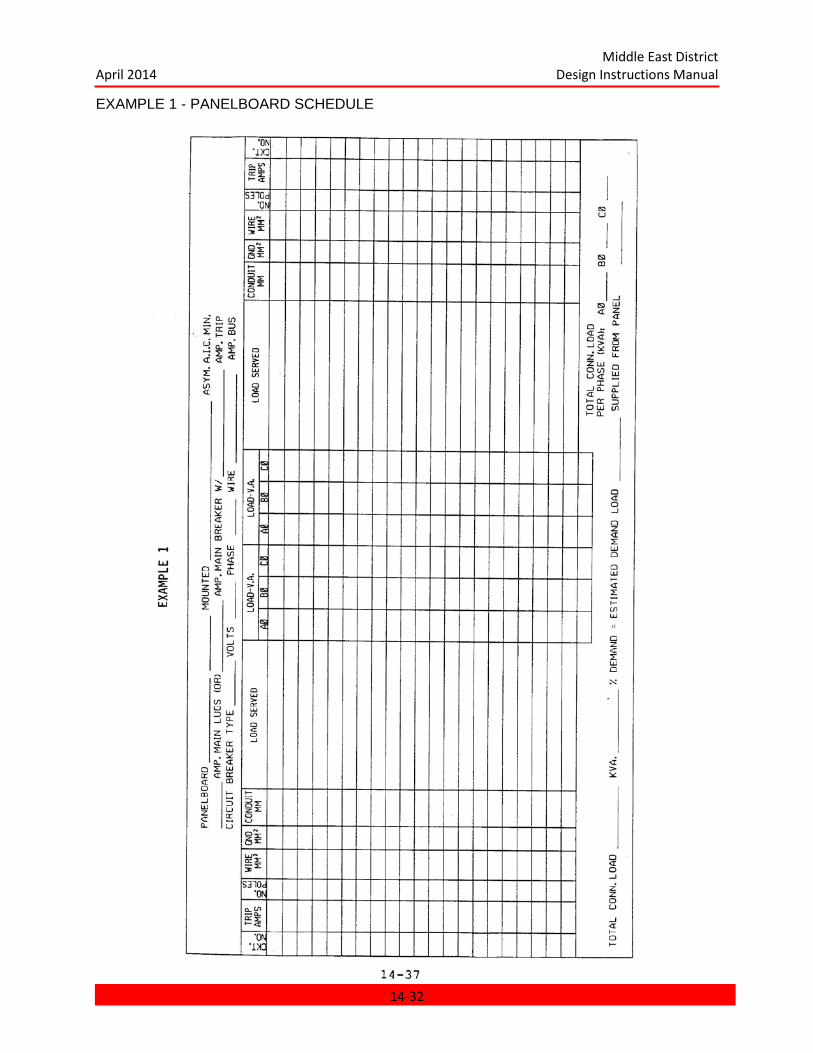
Middle East District April 2014 Design Instructions Manual
EXAMPLE 1 - PANELBOARD SCHEDULE
14-32
Middle East District April 2014 Design Instructions Manual
EXAMPLE 2 - LIGHTING FIXTURE SCHEDULE
14-33
Middle East District April 2014 Design Instructions Manual
CHAPTER 15 POWER GENERATION
CHAPTER 15 POWER GENERATION ................................................................................. 15-1 15.1 GENERAL ..................................................................................................................... 15-2 15.2 APPLICABLE PUBLICATIONS ..................................................................................... 15-2 15.3 CONCEPT SUBMITTAL REQUIREMENTS .................................................................. 15-3
15.3.1 Concept Design Analysis ........................................................................................ 15-3 5.3.2 Concept Design Drawings ........................................................................................ 15-5 15.3.3 Concept Design Specifications ............................................................................... 15-5
15.4 PRELIMINARY SUBMITTAL REQUIREMENTS ............................................................ 15-5 15.4.1 Preliminary Design Analysis ................................................................................... 15-6 15.4.2 Preliminary Design Drawings .................................................................................. 15-6 15.4.3 Preliminary Design Specifications ........................................................................... 15-8
15.5 FINAL SUBMITTAL REQUIREMENTS ......................................................................... 15-8 15.5.1 Final Design Specifications ..................................................................................... 15-8
15.6 READY TO ADVERTISE (RTA) DESIGN REQUIREMENTS ........................................ 15-8 15.7 TECHNICAL REQUIREMENTS .................................................................................... 15-8
15.7.1 Generating Units ..................................................................................................... 15-8 15.7.2 Noise Control .......................................................................................................... 15-8 15.7.3 Intake Air System ................................................................................................... 15-8 15.7.4 Exhaust System ...................................................................................................... 15-9 15.7.5 Ambient Air ............................................................................................................. 15-9 15.7.6 Sandstorms ............................................................................................................ 15-9 15.7.7 Fuel Systems .......................................................................................................... 15-9 15.7.8 Relaying ............................................................................................................... 15-11 15.7.9 Emergency Power ................................................................................................ 15-11 15.7.10 Wiring Methods ................................................................................................... 15-11 15.7.11 Synchronization .................................................................................................. 15-11 15.7.12 Grounding ........................................................................................................... 15-12 15.7.13 Communication System ...................................................................................... 15-12 15.7.14 Energy Management Control (EMC) ................................................................... 15-12 15.7.15 Layout Criteria .................................................................................................... 15-12
15-1
Middle East District April 2014 Design Instructions Manual
CHAPTER 15
POWER GENERATION
15.1 GENERAL.
This chapter gives general guidelines for the preparation of drawings, specifications, and design analysis for power plants and supplements the requirements of Chapter 1 with specific criteria and additional specific design requirements. All required documents including drawings and design analysis shall be in accordance with Chapter 2: PRESENTATION OF DATA.
15.2 APPLICABLE PUBLICATIONS.
The current editions of the publications listed below form a part of this Manual.
U.S. Army Corps of Engineers Publication:
Architectural and Engineering Design Criteria Instructions (AEI).
Department of the Army Technical Manuals (TM):
TM 5-785. Engineering Weather Data.
TM 5-805-4. Noise and Vibration Control for Mechanical Equipment.
TM 5-805-9. Power Plant Acoustics.
TM 5-809-10. Seismic Design for Buildings.
TM 5-810-1. Mechanical Design, Heating, Ventilating, and Air Conditioning.
TM 5-810-4. Compressed Air.
TM 5-810-5. Plumbing.
TM 5-810-6. Non-Industrial Gas Piping Systems.
TM 5-813-3. Water Treatment.
United Facilities Criteria (UFC):
UFC 3-501-01 Electrical Engineering
UFC 3-510-01 Foreign Voltages and Frequencies Guide
UFC 3-520-01 Interior Electrical Systems
UFC 3-540-04N Diesel Electric Generating Plants
15-2
Middle East District April 2014 Design Instructions Manual
UFC 3-550-01 Exterior Electrical Systems
American Society of Heating, Refrigeration, and Air- Conditioning Engineers (ASHRAE) Inc. Standards:
ASHRAE Handbooks, latest editions.
National Association of Plumbing-Heating-Cooling Contractors Codes:
National Standard Plumbing Code.
National Electrical Safety Code (NESC):
National Fire Protection Association (NFPA):
No. 30. Flammable and Combustible Liquid Code.
No. 70. National Electrical Code.
NO. 90A. Installation of Air Conditioning and Ventilating Systems.
No. 91. Blower and Exhaust Systems.
Illuminating Engineering Society (I.E.S.) Lighting Handbook:
Institute of Electrical and Electronic Engineers (IEEE):
IEEE Std. 242 IEEE Recommended Practice for Protection and Coordination on Industrial land Commercial Power Systems (Buff Book).
IEEE Std. 493 IEEE Recommended Practice for Design of Reliable Industrial and commercial Power Systems (Gold Book).
C2 National Electrical Safety Code
Sheet Metal and Air-Conditioning Contractors National Association, Inc. (SMACNA):
Low and High Pressure Duct Construction Standards.
Other Publications:
Industrial Ventilation. A manual of recommended practice, American Conference of Governmental Industrial Hygienists; Lansing, Michigan; Latest Edition (Industrial Ventilation Manual).
15.3 CONCEPT SUBMITTAL REQUIREMENTS.
15.3.1 Concept Design Analysis. The advantages and disadvantages of various
15-3

Middle East District April 2014 Design Instructions Manual
schemes shall be discussed and cost comparisons shall be submitted. Alternative fuel sources shall be discussed. Differing configurations of unit sizes and number of units shall be investigated, and the relative merits (cost, efficiency, maintenance) of each analyzed. Recommendations shall be presented as to how to best serve the load. Climatic and other physical conditions which may affect the reliability of service shall be discussed. The following specific items shall be included when applicable.
15.3.1.1 Power Plant Operation and Control Philosophy shall be discussed and the use of an Emergency Management Control (EMC) system of the power generation system shall be considered.
15.3.1.2 Protective Device Coordination Study. A conceptual protective device coordination study and short circuit analysis of the current and voltages under fault conditions shall be made. The study shall cover all operating arrangements of the system, symmetrical 3-phase faults, line-to-line faults, single phase line-to-ground faults, and double line-to-ground faults. This study shall demonstrate that the proposed configuration can be constructed using equipment with standard ratings and that proper coordination can be achieved using standard devices.
15.3.1.3 Relaying Systems that will be used to protect faulty conditions of circuits of apparatuses shall be discussed.
15.3.1.4 Grounding and Bonding. Discuss the general requirements for grounding and bonding of electrical installations; specific requirements for system grounding such as solid system grounding, resistance system grounding, or reactance system grounding; and the type of grounding for substations or switching stations (for example, upper steel rods, station ground mat, or counterpoise).
15.3.1.5 Prime Movers. A study shall be made to determine the number and type of prime movers to be furnished based on suitability for the particular condition. See paragraph: 15.7.1 Generating Units. Show the selection of these units based on a load study.
15.3.1.6 Load Analysis. Provide a load analysis in the development of the design showing estimated connected load, demand factors which are applied to various loads or areas, and total demand load.
15.3.1.7 Additional Generating Units. Consider the location and space requirements for additional generating units to handle future load growth and expansion.
15.3.1.8 Life-Cycle Cost Comparison. Provide a life-cycle cost comparison of different types and sizes of prime mover generating units.
15.3.1.9 Diversity. Discuss completely the effect that diversity will have in sizing the generating units.
15.3.1.10 Available mVA. State the maximum available short circuit mVA (3-phase
15-4
Middle East District April 2014 Design Instructions Manual
symmetrical).
15.3.1.11 Auxiliary Power Requirements for control and black startup (such as standby electrical power and station batteries as applicable) shall be discussed.
15.3.1.12 Cathodic Protection of underground metallic pipes, structures, buried tanks, lead-covered cables, and equipment in manholes shall be considered.
15.3.1.13 Power Plant Communication System. If a power plant communication system is required, it shall be discussed. Indicate the method of operation of plant intercommunication systems for use between various handset locations and for paging personnel throughout the power plant, administration building, or warehouse. See Chapter 17: COMMUNICATIONS.
15.3.1.14 Building Lightning Protection to be provided for generating plants shall be discussed.
15.3.1.15 Fire Alarm System. Discuss required fire alarm systems and the type of fire and smoke detectors to be used. See Chapter 9: FIRE PROTECTION AND LIFE SAFETY.
15.3.1.16 Power Plant Security System. If a power plant security system is required, it shall be discussed. See Chapter 9: FIRE PROTECTION AND LIFE SAFETY.
15.3.1.17 Power Plant Mechanical Systems. Discuss required HVAC and plumbing systems and the method of operation. See Chapter 10: HEATING VENTILATING AND AIR CONDITIONING, and Chapter 11: PLUMBING.
5.3.2 Concept Design Drawings. The following specific items shall be shown when applicable.
15.3.2.1 Plant Drawings shall show the proposed location of generating units, engine auxiliaries room, machine shop and spare parts storage, transformers, switchgear, switchyards, and control room. The plans shall indicate fuel supply storage and handling.
15.3.2.2 Flow diagrams of all HVAC, Plumbing and Generator Auxiliary systems, including Fuel Storage and Supply System, Cooling System, and Compressed Air System. These diagrams shall be an accurate schematic representation of each system showing proposed equipment, primary control accessories, and piping as applicable.
15.3.2.3 Single-Line Diagrams. Provide complete ac and dc system single-line diagrams for buildings, including package system auxiliaries such as diesel or gas turbine generators.
15.3.3 Concept Design Specifications. Concept design specifications shall be submitted in accordance with Chapter 3: SPECIFICATIONS.
15.4 PRELIMINARY SUBMITTAL REQUIREMENTS.
15-5
Middle East District April 2014 Design Instructions Manual
15.4.1 Preliminary Design Analysis. A design analysis shall be required as part of the Preliminary design submittal in support of information depicted on the plans. The analysis shall include all items in the concept design analysis and any necessary revisions. It shall indicate computations, references, any assumptions made in the design, and shall indicate criteria on which the design is based. Complete calculations shall be submitted for the following items.
15.4.1.1 Maintained Foot-Candle Intensities in all areas shall be provided.
15.4.1.2 Demand Load Summary. Provide a summary of feeder demand, connected loads, overall demand load at generating plant and overall demand load for area to be served; give quantity and type of conductors, type of conduit, minimum rating of feeder bus duct, voltage drop calculations, and actual size and type of overcurrent devices including interrupting capacity and transformer capacity.
15.4.1.3 Protective Device Selectivity. In addition to the short circuit analysis required in paragraph: Protective Device Coordination Study of the Concept design analysis, protective device selectivity assuring that a faulted circuit is cleared and that no other parts of the system are affected shall be considered.
15.4.1.4 Relay and Circuit Breaker Settings. Provide calculations for recommended relay and circuit breaker settings.
15.4.1.5 Selection Factors. Provide all demand,
diversity, ambient temperature, or derating factors considered in the selection of equipment and conductors.
15.4.1.6 Design Data and Loads. Provide structural and mechanical design data and design loads. Mechanical design to include equipment heat rejection, cooling system, room ambient temperature and equipment temperature deration.
15.4.1.7 Computer Printouts submitted as part of computer fault studies shall have the inputs and outline of the computer program. A one-line diagram with lines and feeder references shall be provided. An impedance diagram shall be provided.
15.4.1.8 Electrical Characteristics. Discuss the electrical characteristics of the supply to the facility or portion thereof involved. Include in this discussion the interrupting capacity of devices intended to break current and the bus bracing requirements of electrical equipment housing these devices. Electrical characteristics shall be in accordance with TM 5-811-1 unless otherwise stated in this Manual.
15.4.2 Preliminary Design Drawings. Preliminary design drawings shall incorporate the following requirements.
15.4.2.1 Plan Drawings shall show the location of all major items or equipment, including the following.
15-6
Middle East District April 2014 Design Instructions Manual
a. High voltage switchgear.
b. Low voltage distribution equipment.
c. Control panels.
d. Instrumentation panels.
e. Lighting panelboards.
f. Power panelboards.
g. Motor control centers.
h. Prime mover details.
i. Lightning protection.
j. Telephone cabinets.
k. Automatic transfer switches.
l. Emergency generators.
m. Magnetic motor starters.
n. Lighting.
o. Site plan details.
p. All HVAC, plumbing and other building equipment including air conditioning, exhaust fans, and overhead door operators.
q. Special operating equipment such as compressors, radiators, pumps, and bridge cranes.
r. Fuel bulk storage and day tanks.
15.4.2.2 Power Distribution Features. All major items of equipment shall be sized and properly identified to agree with electrical plans. All motor control circuits shall be explained with basic schematic diagrams (ladder type) on the plan drawings. Power distribution features shall include the following detailed single-line diagrams of the electrical system.
a. Primary power.
b. Central power plant building.
c. Motor control center.
15-7
Middle East District April 2014 Design Instructions Manual
d. Direct current for battery systems.
e. Generator auxiliaries.
15.4.2.3 Power and Control Wiring. Plan drawings shall show location and routing circulation of all power and control wiring.
15.4.2.4 Grounding. Show the grounding necessary for power plant building, outdoor substations, outdoor switching stations, transmission lines, chimneys, flagpoles, and ordinary buildings. Show details for all unusual grounding requirements including those for transformer pads, all ac generating equipment, dc generators and rectifiers, static grounds, lightning protection, and primary equipment.
15.4.3 Preliminary Design Specifications. Preliminary design specifications shall be submitted in accordance with Chapter 3: SPECIFICATIONS.
15.5 FINAL SUBMITTAL REQUIREMENTS.
The design analysis and the drawings submitted for Final review shall be complete, as described in Chapter 1: GENERAL INSTRUCTIONS.
15.5.1 Final Design Specifications. Final design specifications shall be submitted in accordance with Chapter 3: SPECIFICATIONS.
15.6 READY TO ADVERTISE (RTA) DESIGN REQUIREMENTS.
The comments generated during the Final design review shall be incorporated in the documents before they are submitted as Ready To Advertise (RTA).
15.7 TECHNICAL REQUIREMENTS.
15.7.1 Generating Units. Life-cycle cost analyses will be made, and site elevations, ambient conditions, etc. must be considered for proper selection of the type and size of generating units. In addition, factors peculiar to each generating station must be considered. Examples of these factors include the following: availability and cost of water, logistics of fuel supply, types of fuel available to the site, future expansion considerations, future ties to commercial power, use of heat recovery, standardization of module size, market availability of competitively sized units, and system availability analyses. Analysis described in UFC 3-540-04N shall be followed.
15.7.2 Noise Control. Noise control design shall be in accordance with TM 5-805-9.
15.7.3 Intake Air System. The air intake system consists of an air inlet filter system, air inlet silencer, and connecting ducts capable of providing clean air. Total pressure drop across the inlet system shall be kept to a minimum (not to exceed 3 inches of H20). Location of the inlet shall be such that contaminants from exhaust, tank vent vapor, etc., are kept to a minimum. The
15-8
Middle East District April 2014 Design Instructions Manual
inlet air filter system shall include an inertial type filter to remove the larger particles, followed by intermediate and high efficiency stages of filtration. Installations also require filtration to remove salt from the inlet air.
15.7.4 Exhaust System. The exhaust system ductwork must be terminated in a manner that precludes recirculation of exhaust products through the air intake or cooling radiator. The height of exhaust duct above air inlet, the building roof design, the direction of prevailing wind, and the proximity of adjacent structures must be considered. Where two or more units exhaust into a common header such as that used for heat recovery equipment, provisions must be made to prevent hot gas from flowing into the nonoperative units.
15.7.4.1 Heat Reclamation. At any installation which produces prime power from diesel engines or gas turbines consider the use of waste heat boilers to reclaim all possible heat economically consistent with the total heating and/or air-conditioning requirement of the installation. An economic study shall be made to determine the feasibility of using heat from waste heat boilers and engine jacket water heat recovery equipment.
15.7.4.2 Exhaust Silencing. When exhaust silencing is required, provisions shall be made to mount and support the equipment adequately and to limit the silencer pressure.
15.7.5 Ambient Air. The combination of arid desert climate, generally poor water supply, and high temperatures requires special consideration with respect to power generation facilities design. When the water supply is generally inadequate, dry air cooling shall be provided. The use of dry air cooling results in larger heat exchanger surfaces and greater fan horsepower than would be required for evaporative cooling. High ambient temperatures in comparison to typical U. S. and European temperatures, reduces the theoretical and actual thermodynamic conversion efficiencies of generating units. Ambient air temperatures within generation facility
buildings can exceed 65o C (150
o F) near generating units, imposing a requirement for special
concern about the cooling of generators and other items which may be affected by high local air temperatures.
15.7.6 Sandstorms. Sandstorms are a climatic threat to power plants. Obviously, the entrance of dust and/or sand into an engine or turbine would have serious deleterious effects on the internal working parts. Although highly effective inlet air infiltration may be required for routine operation, it is unlikely that such filtration would be adequate during sandstorm conditions. During such periods it would be necessary either to use additional high efficiency filters in the inlet air stream, to reduce power output to supply essential needs only, or to do both.
15.7.7 Fuel Systems.
15.7.7.1 Fuel Oil and Crude Oil. Base load generating stations will be provided with facilities to handle Grades 1 and 2 fuel oil and light crude oil. Systems will be designed for primary use of Grade 1 and 2 fuel oil with crude oil as standby. Space will be provided for future installation of a natural gas line. Alternate fuel sources shall be considered as required by the
15-9

Middle East District April 2014 Design Instructions Manual
Scope of Work.
15.7.7.2 Natural Gas. The natural gas fuel system includes all components necessary to control fuel at the proper schedule during starting and operating, from no load to full load. The gas supply should be at a regulated pressure of 165 to 200 psig.
15.7.7.3 Liquid Fuel. Fuel systems consist of the following major parts.
a. Booster pump and strainer.
b. 10-micron, low pressure, duplex filter replaceable element).
c. Main turbine or engine driven fuel pump.
d. High pressure filter (10-micron).
e. Main fuel control (combines the functions of the acceleration control and the fuel metering valve) controlled by governor actuator.
f. Valve block (provides manifolding and mounting for shutoff valve, bypass valve, purge valve, and igniter valve).
g. Fuel manifold block for distributing fuel to the fuel injectors.
h. Fuel washing system for crude oil only.
i. Oil heating system for crude oil only, when required.
15.7.7.4 Dual Fuel System. The dual fuel system combines all the features of the natural gas fuel system and the liquid fuel system, and includes the controls for fuel changeover during operation. Two basic types of systems are discussed below.
a. The engine-driven main liquid fuel pump system includes an offset fuel cooler for eliminating the heat dissipated into the fuel by the engine driven fuel pump while the unit is running on gas fuel. The boost pump for this system shall be the jet type system.
b. With an ac motor-driven pump system, the motor driven pump is shut down when the unit is running on gas fuel, thus deactivating the liquid fuel system. A return-to-tank liquid line is not required.
15.7.7.5 Fuel Storage. In addition to the day tank, underground storage shall be provided for all generating plants covered by this Manual. The storage tank shall be of sufficient capacity to operate the plant for two weeks using No. 2 fuel oil during the months of largest average demand. Actual fuel consumption of the engines and estimated number of hours of operation shall be used in determining the capacity of the storage tank. A maximum of one-half of the total storage tanks will be piped to dispense both No. 2 fuel oil and light crude oil with
15-10
Middle East District April 2014 Design Instructions Manual
proper valving to guard against pumping into the wrong system.
15.7.8 Relaying. Protective relaying will cause the prompt removal of any element of a power system when it suffers a short circuit or when it starts to operate in any abnormal manner. The protective relaying system shall detect a failure or abnormal condition quickly and commensurate with system requirements. Relays will open a minimum of overcurrent protective devices to isolate the defective element. Quick isolation will minimize or prevent damage to the defective element and will minimize the seriousness and duration of the defective element's interference with normal operation of the rest of the power system. Relays shall be suitable for use with the frequency.
15.7.8.1 The Relaying Scheme shall be selective and shall meet the following conditions.
a. Minimum disturbance of the system by isolating the fault from the remainder of the system.
b. Discrimination between genuine faults and abnormal conditions that do not require tripping of circuit breakers (for example, locked rotor in-rush currents of motors).
15.7.8.2 Backup Relaying shall be provided only when the original relaying scheme can be designed to incorporate backup as an inherent feature of the relaying scheme.
15.7.8.3 Current Transformers for Differential Relaying shall not be used for any purpose than differential relaying.
15.7.9 Emergency Power. Provide an uninterruptable power supply (UPS) for reliable power to critical control and/or protection systems for black start, proper operation, or safe shutdown of the generator upon complete loss of the ac auxiliary power system.
15.7.9.1 Transfer Switch. Provide an automatic solid state transfer switch for the UPS. During normal operation, the UPS will be powered by the ac system, with automatic transfer to the dc system upon loss of ac power.
15.7.9.2 Stored Energy Starting. Stored energy starting may be used where only short interruptions of power is permissible. Energy is stored in batteries, capacitors, flywheels, pneumatic pressure vessels, and similar units. The energy shall be utilized in a particular fashion to provide service during interruption of prime mover service until emergency generation is available.
15.7.10 Wiring Methods. See paragraph: Wiring Methods in Chapter 14 of this Manual.
15.7.11 Synchronization. Generator units will be paralleled via synchronizing bus when operating in parallel. Operation of the system shall have provisions for manual and
15-11
Middle East District April 2014 Design Instructions Manual
automatic start. A synchronizing relay, which will bring selected units on line, will sense voltage on the bus and either close the breaker when the incoming unit is in phase with the voltage or close immediately if there is no voltage on the bus. With the synchronizing switch turned on the operator shall have the option to manually put a unit(s) on the line by watching a synchroscope and closing the circuit breaker switch at the proper synchronous point.
15.7.12 Grounding. For power generating plants, a grid type ground system shall be installed around the building. Each ground grid shall consist of buried loop copper wire, not smaller than number 4/0, which encircles the area. Ground rods shall be driven along this loop. A number of cross-connections shall be installed to connect building steel and equipment to the ground grid in such a way that each major piece of equipment or structure has common ground paths. The individual ground grids shall be ties together with an interconnecting ground wire. Building steel and conductive enclosures of electrical equipment shall be connected to the ground system. The ground system shall be in accordance with the National Electrical Code and National Electrical Safety Code, taking into account conditions encountered at the particular location.
15.7.13 Communication System. A telephone system shall be provided for power plants. This system shall be in accordance with Chapter 17: COMMUNICATION. When required by the contract, a complete plant intercommunication system shall be provided for use between various handset locations and for paging of personnel throughout the power plant and auxiliary Buildings.
15.7.14 Energy Management Control (EMC). The use of EMC for power plant operation and control shall be considered. An Energy Management System eliminates the requirements for many operators, reducing the overall manpower requirements, and decreasing the margin of human errors. An EMC system has the following capabilities.
a. An EMC system enables the operator to monitor the operating status of (on-off) functions from a central control station.
b. The system can measure variables such as temperature, flow, and pressure.
c. EMC has alarm capabilities for out-of-tolerance conditions.
d. Control interfaces with central HVAC systems and/or central control monitoring systems are possible.
e. The EMC system can also be used to shed noncritical loads if and when the demands of the plant exceed its generating capacity.
15.7.15 Layout Criteria. Layout shall provide easy access to all equipment and shall minimize daily maintenance time required. (For example, all motor starters shall be ground together in motor control centers, and a central instrumentation and control panel shall be provided.)
15-12
Middle East District April 2014 Design Instructions Manual
CHAPTER 16 POWER TRANSMISSION AND DISTRIBUTION
CHAPTER 16 POWER TRANSMISSION AND DISTRIBUTION ........................................... 16-1 16.1 GENERAL ..................................................................................................................... 16-2
16.2 Applicable Publications .............................................................................................. 16-2 16.3 CONCEPT SUBMITTAL REQUIREMENTS .................................................................. 16-3
16.3.1 Concept Design Analysis ........................................................................................ 16-3 16.3.2 Concept Design Drawings ...................................................................................... 16-3 16.3.3 Concept Design Specifications ............................................................................... 16-4
16.4 PRELIMINARY SUBMITTAL REQUIREMENTS ............................................................ 16-4 16.4.1 Preliminary Design Analysis ................................................................................... 16-4 16.4.2 Preliminary Design Drawings .................................................................................. 16-4 16.4.3 Preliminary Design Specifications ........................................................................... 16-5
16.5 FINAL SUBMITTAL REQUIREMENTS ......................................................................... 16-5 16.6 READY TO ADVERTISE (RTA) DESIGN REQUIREMENTS ........................................ 16-5 16.7 TECHNICAL DESIGN REQUIREMENTS ...................................................................... 16-5
16.7.1 Selection of Distribution Systems ............................................................................ 16-6 16.7.2 Conductor Selection ............................................................................................... 16-6 16.7.3 Transformers .......................................................................................................... 16-6 16.7.4 Circuit Design ......................................................................................................... 16-9 16.7.5 Underground Construction .................................................................................... 16-10 16.7.6 Voltage Drop ......................................................................................................... 16-11 16.7.7 Circuit Protection .................................................................................................. 16-11 16.7.8 Reliability .............................................................................................................. 16-12
16-1
Middle East District April 2014 Design Instructions Manual
CHAPTER 16
POWER TRANSMISSION AND DISTRIBUTION
16.1 GENERAL.
This chapter gives guidelines for the preparation of drawings, specifications, and design analysis for power transmission and distribution. It supplements the general requirements of Chapter 1: GENERAL INSTRUCTIONS and Chapter 14: ELECTRICAL with specific criteria and additional specific design requirements. All required documents, including Drawings and Design Analysis, shall be in accordance with Chapter 2: PRESENTATION OF DATA.
16.2 Applicable Publications.
The current edition of the publications listed below, form a part of this manual.
Department of the Army Technical Manual (TM):
TM 5-765. Electric Power Transmission and Distribution.
TM 5-811-1. Electrical Power Supply and Distribution.
Corps of Engineers Guide Specifications (CEGS):
Standard Drawings. Electrical Distribution Construction, Standard Detail No. 40-06-01.
CEGS. Electrical-Distribution and Street-Lighting System; Underground.
CEGS. Electrical-Distribution and Street-Lighting System; Aerial.
American National Standards Institute (ANSI):
ANSI C2 National Electrical Safety Code
National Electrical Manufacturers Association (NEMA) Standards:
Insulation Power Cable Engineers Association (IPCEA):
National Fire Protection Association (NFPA):
NFPA-70. National Electrical Code (NEC).
NFPA Lightning Protection Code.
NFPA 101. Life Safety Code.
Institute of Electrical and Electronics Engineers, Inc. (IEEE) :
IEEE Transactions. Standard Basic Impulse Insulation Levels".
16-2
Middle East District April 2014 Design Instructions Manual
IEEE Std. 141. Recommended Practice for Electric Power Distribution for Industrial Plants. (Red Book)
IEEE Std. 142. Recommended Practice for Grounding of Industrial and Commercial Power Systems (Green Book).
IEEE Std. 242. Recommended Practice for Protection and Coordination of Industrial and Commercial Power Systems (Buff Book).
Naval Facilities Engineering Command:
MIL-HDBK-1004/1 Electrical Engineering Preliminary Design Considerations.
MIL-HDBK-1004/2 Power Distribution Systems.
MIL-HDBK-1004/3 Switchgear & Relaying.
MIL-HDBK-1004/4 Electrical Utilization Systems.
MIL-HDBK-1004/6 Electrical Engineering Lightning Protection Systems.
16.3 CONCEPT SUBMITTAL REQUIREMENTS.
Specific requirements for concept documents are given below. These requirements are in addition to the general requirements of Chapters 1 and 2.
16.3.1 Concept Design Analysis. The Concept design analysis shall include a narrative, identifying systems, and a description of the method of distribution with supporting rationale. The following specific items shall be included when applicable.
16.3.1.1 Fault Calculations and Protective Coordination Study. Provide fault calculations and a protective coordination study for the system. The design analysis shall include a simplified single-line diagram in support of fault calculations. Show all equivalent resistances, reactances, and interrupting capacities on the single-line diagram. Short circuit calculations shall be coordinated with the requirements of Chapter 15: POWER GENERATION if required.
16.3.1.2 System Design Calculations shall include an estimate of the total connected and demand loads as well as individual feeder loads.
16.3.1.3 Primary Voltage Selection. Provide the rationale and economic justification for selection of the primary voltage.
16.3.1.4 Selection of Equipment and Material. Include any assumptions or conditions peculiar to the project which will effect selection of equipment and material. For example, if derating factors are used in determining cable ampacities, transformer capacities, etc., these factors must be clearly stated in the design analysis and supporting data given to show how factors were determined.
16.3.2 Concept Design Drawings. The following specific items shall be shown when applicable.
16-3
Middle East District April 2014 Design Instructions Manual
16.3.2.1 Proposed Distribution. Show proposed routing of electrical distribution and street lighting systems.
16.3.2.2 Electrical Distribution System Diagram. Provide a single-line diagram of the electrical distribution system showing a tie-in with the local or municipal plant.
16.3.3 Concept Design Specifications. Provide concept design outline specifications as described in Chapter 3: SPECIFICATIONS.
16.4 PRELIMINARY SUBMITTAL REQUIREMENTS.
16.4.1 Preliminary Design Analysis. A design analysis shall be required as part of the Preliminary design submittal in support of information depicted on plans. The analysis shall include computations and shall indicate criteria on which the design is based, references approximately indexed, and any assumptions made in the design.
16.4.1.1 Complete Manual and/or Computer calculations shall be submitted for the following.
a. Short circuit performance of bare overhead conductors and underground cables including thermal stresses on conductors, worst-case fault conditions, and single-phase short circuit currents which are the most frequent type to occur shall be indicated.
b. Calculations to support the strength requirements used to select the proper size poles, insulators, guying, anchors, and foundation details.
c. Calculations to select the proper rating of electrical components such as lightning arresters, disconnect switches, fused cutouts, and insulators.
e. Structural calculations as required to support the electrical design.
f. Feeder calculations including all derating factors.
16.4.1.2 Distribution at 50 Hertz. When the project requires distribution at a 50 Hz frequency, use tables, charts, and graphs suitable for 50 Hz or add appropriate correction factors.
16.4.1.3 Worst-Case Voltage Drops. Include computations in the design analysis for worst-case voltage drops.
16.4.1.4 Roadway or Area Lighting. When roadway lighting or area lighting is required, provide lighting calculations in accordance with Chapter 14: ELECTRICAL.
16.4.1.5 Soil Boring Data. Provide all pertinent soil boring data when special pole bracing or footings are required for subnormal soil bearing conditions.
16.4.2 Preliminary Design Drawings. Preliminary design drawings shall incorporate the following requirements.
16.4.2.1 Plan Drawings. Provide plans showing the underground distribution, telephone and fire alarm systems. Consideration shall be given to establishing right-of-way clearances,
16-4

Middle East District April 2014 Design Instructions Manual
manhole and ductline spacing, and any special space or physical protection requirements. Aerial distribution will only be considered for temporary installations, unless specifically directed otherwise in the Scope of Work.
16.4.2.2 Details. Details for plan drawings shall include but not be limited to the following items when applicable.
a. Overhead line construction details and transpositions.
b. Underground line construction details and sections.
c. Guying of poles.
d. Manhole details (check proper sizing).
e. Special pole setting foundation details.
f. Distribution transformer details.
g. Transformation connections (Ex: A-Y).
h. Grounding details.
i. Exterior substation and switching stations.
j. Overcurrent protection and control equipment.
k. Tower line construction.
l. Schematic Diagrams.
m. Where ductbanks are used, profiles of ductbank and manhole elevations, coordinated with civil topographical drawings and other underground utilities.and manhole elevations, coordinated with civil topographical drawings and other underground utilities.
16.4.3 Preliminary Design Specifications. Provide preliminary design specifications in accordance with Chapter 3: SPECIFICATIONS.
16.5 FINAL SUBMITTAL REQUIREMENTS.
The Design Analysis and drawings submitted for Final Review shall be complete, as described in Chapter 1: GENERAL INSTRUCTIONS. Specifications shall be prepared per Chapter 3: SPECIFICATIONS.
16.6 READY TO ADVERTISE (RTA) DESIGN REQUIREMENTS.
The comments generated during the Final Design Review shall be incorporated in the documents before they are submitted as Ready To Advertise.
16.7 TECHNICAL DESIGN REQUIREMENTS.
16-5
Middle East District April 2014 Design Instructions Manual
16.7.1 Selection of Distribution Systems. In choosing the distribution system, the designer must consider load requirements, permissible voltage regulation, reliability, flexibility, and initial cost. The following systems as listed in MIL-HDBK -1004/2 are available.
16.7.1.1 Conventional Simple-Radial Distribution System.
16.7.1.2 Modern Simple-Radial Distribution System. The modern simple-radial distribution system can be used for capacities in excess of 1,000 kVA. The length of low-voltage feeders shall be kept to a minimum, reducing cable cost and energy losses. Size each transformer to handle the peak load of the area served.
16.7.1.3 Modified Modern Simple-Radial Distribution System.
16.7.1.4 Loop Primary-Radial Distribution Type.
16.7.1.5 Banked Secondary-Radial Distribution System.
16.7.1.6 Primary Selective-Radial Distribution System.
16.7.1.7 Secondary Selective-Radial Distribution System.
16.7.1.8 Simple Network Distribution System.
16.7.1.9 Simple Spot-Network Distribution System. The simple spot-network distribution system shall be used for installation that have heavy loads concentrated in small areas with a considerable distance between each other.
16.7.1.10 Primary Selective Network Distribution System. The primary selective network distribution system shall be used for industrial applications in which heavy loads are evenly distributed.
16.7.1.11 Primary Selective Spot-Network Distribution System.
16.7.2 Conductor Selection. Primary cable systems shall be selected in accordance with the following Standard Corps of Engineers Guide Specifications (CEGS).
a. Electrical-Distribution and Street-Lighting System; Underground.
b. Electrical-Distribution and Street-Lighting System; Aerial.
16.7.3 Transformers. Transformers shall be of the self cooled type, with rating selected from Standard NEMA tables where the required size is not listed in the table, the next larger size should be installed unless the next smaller size will provide at least 90 percent of the required rating. Wye-wye connected transformers should not be utilized. All transformers installed outdoors or in fire proof transformer vaults should be of the oil-insulated, self-cooled type. Transformers installed within buildings in which fireproof vaults have not been provided shall be of the dry type (ventilated or sealed as appropriate).
16.7.3.1 Transformer capacities shall be selected so that all transformers will be operating as nearly as practicable to the allowable temperature limits during periods of maximum demand. Transformer derating shall be applied as required by NEMA Standards TR 27 "Commercial, institutional and industrial dry-type transformer" and TR 98 "Guide for loading
16-6
Middle East District April 2014 Design Instructions Manual
oil-immersed power transformers with 65, C average winding rise". Special derating should be addressed for loads having high harmonic neutral currents.
16.7.3.2 Distribution transformers, pad-mounted compartmental type, single-phase, three-phase oil-filled and dry type shall be utilized where it is not advantageous to use secondary or primary unit substations. The transformer and associated terminal compartments shall be tamper proof, protected from the unusual site service conditions and derated for altitude and ambient temperatures as appropriate. Compartmental pad mounted transformers shall be comprised of air filled incoming and outgoing terminal compartments. The high voltage bushings in the incoming compartment shall consist of appropriate high voltage fuses. The outgoing compartment shall consist of low voltage bushings as required for system distribution.
16.7.3.3 Secondary unit substation shall be utilized where the low voltage section is rated 1000 volts or less and shall consist of the following.
a. Incoming section providing connection of one or more incoming H.V. circuits, each of which may or may not require a switching device or a switch and interrupting device.
b. Transformer section including one or more transformers.
c. Outgoing section for connection of one or more outgoing feeders, each of which is provided with a switching and interrupting device. These sections shall be either preassembled at the factory or sub-assembled in field as appropriate.
16.7.3.4 Primary unit substations shall be utilized where the low voltage section is rated above 1000 volts and with incoming transformers and secondary sections indicated above for the secondary unit substations.
16.7.3.5 Transformers should be located as close to the center of the secondary load as practicable and should preferably be located in buildings. Where the installation of transformers in buildings is not practicable, such as in housing areas, compartmental type transformers should be installed on outdoor concrete foundations.
16.7.3.6 When exterior pad-mounted transformers are located in the vicinity of any vehicular traffic, install heavy-duty traffic barriers around the transformer. Locate outdoor installation so that the equipment and enclosure will be as inconspicuous as possible and, with the addition of shrubbery, will fit properly into the landscaping layout.
16.7.3.7 Oil Filled Transformers 2,000 kVA through 10,000 kVA. In general, oil-filled transformers 2,000 kVA and larger operating at voltages not exceeding 15 kV and electrically remote from generating stations (low X/R ratio) shall have the following protective measures.
a. Circulating current differential protection, utilizing percentage differential relays of the induction type.
b. Rate of pressure rise relay (for hermetically sealed transformers).
c. Overcurrent and ground fault relays, directional or non-directional, as required to ensure selectivity.
16-7

Middle East District April 2014 Design Instructions Manual
d. Over pressure detector wired to give alarm in attended substations and to disconnect the transformer in unattended substations.
e. Winding and oil over temperature detection wired to give alarm in attended substations and to disconnect the transformer in unattended substations.
f. Interlocks and alarms to ensure that all auxiliaries (fans, pumps, and similar items) are in working order.
16.7.3.8 Oil Filled Transformers Below 2,000 kVA and All Dry Transformers. Fuses shall normally be used for primary protection of transformers. However, should primary circuit breakers (medium voltage) be provided, overcurrent and ground fault relays shall be used.
16.7.3.9 Protection of Switchgear. Substations of primary importance shall have some form of bus bar differential relaying. Substations of secondary importance will not normally warrant bus bar protection. In any case, switchgear must be capable of withstanding, both mechanically and thermally, the largest available fault currents. All current transformers for bus bar differential relaying shall be the same ratio and type. Bus differential relaying shall be installed on the line side of circuit breakers to minimize outages due to malfunction of the main differential system. The tripping of all circuit breakers connected to bus bars should not occur unless both relays have operated. Special arrangement shall be made to facilitate frequent maintenance and testing of the installation with the bus in service. The risk of accidental tripping shall be reduced to a minimum.
16.7.3.10 Outdoor vs Indoor Substations. If a substation shall have an attendant constantly on the premises, then shelter and a room in which to work, i.e., a building, shall be required. As a minimum, the building would house the control board, telephone, control battery and charger, and any other devices that are normally built only for indoor service. Otherwise, it is more practical to build new unattended substations outdoors.
16.7.3.11 Bus Arrangement: The selection of the substation bus arrangement shall depend upon the cost, the application, and the required degree of service continuity and reliability.
16.7.3.12 Lightning Arresters shall be included in substations connected to overhead lines. Where possible, on high voltage systems the neutral shall be permanently connected to ground for a more effective arrester. The resultant lower impulse voltage obtained by grounding the neutral will allow for a more economical installation since lower impulse installation ratings may be used in selecting other equipment and components.
16.7.3.13 Connections to Existing Distribution Systems. When the project requires extension of or tapping into an existing medium voltage distribution system, the connection must be done in a way approved by the local organization responsible for the existing distribution system. Generally this requires the use of a ring main unit (RMU), loop switch, or sectionalizing switch. "T" splices are generally not acceptable. The designer shall provide sufficient documentation to the local authority to obtain approval for the connection and provide a record of the approval in the design analysis. The design analysis shall also contain all information about the existing distribution obtained by the designer during the course of the design. On site involvement by the designer, either to obtain design data or to coordinate with the local authority for approval of the design, shall be as defined in the general scope of work.
16-8
Middle East District April 2014 Design Instructions Manual
16.7.4 Circuit Design. The proper procedure for the design of circuits may be ascertained from the list of detailed data in Table A.
TABLE A Information Required for Circuit Design
Item Specific information required
Voltage, phase 13.8 kV, 3 phase, 480/277V, 3 phase,208/120V, 3 phase.
Load Location, magnitude, load factor, peak load, coincidence factor.
Peak load For each circuit, point where power feeds into circuit.
Voltage drop For peak load. For each phase, if circuit is multi phase with unbalanced load.
Motor load Add to normal load currents on circuit.
16.7.4.1 Criteria. Use the following criteria for design.
a. Provide for spare capacity in each circuit where required by design.
b. Select the wire size in accordance with the current carrying capacity required.
c. Size regulating devices in accordance with the amount of regulation required.
d. Choose the type of regulators from fixed capacitors, switched capacitors, single-step boosters, multi step regulators, and induction regulators as required.
e. Provide line drop compensation for automatic operation when these regulators are used on more than one source or when more than one regulator is used on a single circuit.
f. Select physical design features in accordance with type of circuit involved and the type of distribution, that is, primary or secondary. Select from the following types.
1. Direct burial single or multi-conductor.
2. Duct encased single or multi-conductor.
3. High and low voltage in cable tray.
16.7.4.2 Grounding. Provide grounding for all equipment and structures associated with electrical systems to prevent shock from static or dynamic voltages. For information on grounding of overhead distribution systems, see the National Electrical Safety Code, Part 2.
16.7.4.2.1 Ground resistance. Provide a low impedance path at the source of fault currents if a circuit contains a deliberate ground connection.
16.7.4.2.2 Maximum ground resistance. Consult the National Electrical Safety Code,
16-9
Middle East District April 2014 Design Instructions Manual
Part 2. Consider the source or power, capacity, magnitude of fault current, and method of system grounding, as they affect this resistance.
16.7.4.2.3 Grounding methods.
a. Water pipe connection. The electrical system may be grounded to a water supply system except where nonmetallic pipes or insulating couplings are incorporated in the water pipe systems.
b. Ground rods. Ground rods may be used either singly or in clusters. Drive the ground rods to ground level for effective and permanent installation. Provide for corrosion prevention by a proper choice of metals or by cathodic protection. Where ground water cannot be reached, chemicals such as salt or calcium chloride should be used to improve soil conductivity. Provide for easy maintenance and periodic testing. Protection against lightning shall comply with NFPA-78.
c. Grounding network. In poor soil, effective safety grounds shall be obtained by the use of a buried network of ground conductors. If meshes are made small enough, the control of surface voltage gradients can be obtained even though the ground resistance may be relatively high.
d. Combination of grounding methods. Where the ground resistance in an existing system is high, any of the aforementioned methods, either singly or in combination, may be used to effect improvement.
e. Underground Distribution Systems. All manholes and handholes in an underground distribution system shall be provided with an integral ground rod. A copper ground counterpoise conductor shall be run above all power ductbanks.
16.7.5 Underground Construction. Underground construction shall be in accordance with TM 5-765 and TM 5-811-1. Underground system is to be a long-life installation that will be adequate for any foreseeable degree of expansion during the life of the facility.
16.7.5.1 Route. The first problem in preparing an underground line system is selection of the route. This is important whether or not the cables are laid in ducts or buried directly in the earth. An accurate map should be made showing the location of fire hydrants, street-light standards, curb lines, buildings to be served, and points of entrance for service to buildings. The map should also show the subsurface obstructions. A route should be selected which will require as few curves and bends as possible and which will not have to be placed at too great a depth. The route should avoid the following obstructions.
a. Gas mains and gas service laterals.
b. Telephone and other communication duct lines and laterals.
c. Sewer mains, manholes, and service connections.
d. Water mains and service laterals.
e. Storm sewers and catch basins.
16-10
Middle East District April 2014 Design Instructions Manual
f. Steam pipes.
g. Chilled water pipes.
16.7.5.2 Direct Burial. In general, direct burial cable installations shall be limited to secondary voltage and street lighting systems in uncongested areas.
16.7.5.3 Duct System. The duct system shall be used for all primary voltage, telephone and fire alarm systems or when direct burial cables are subject to mechanical damage. The nominal diameter of ducts for primary cables shall not be less than 4 inches. Where power and communication cables are routed in the same duct bank the nominal diameter of ducts shall also not be less than 4 inches. A sufficient number of spare ducts shall be provided for future installation of a minimum 25 percent increase in the initial number of cables. Distances between manholes, service boxes, and ducts shall be as required by the Department of the Army Technical Manual, TM 5-765 and TM 5-811-1. Do not use a duct bank containing more than 16 ducts because of cable arrangement in manholes and best heat dissipation. Usually if more than 12 ducts are needed, a separate bank is installed with minimum separation of 2 feet of earth.
16.7.5.4 Ducts. Service ducts shall be limited to a length of about 125 feet. The main conduit shall not be over 500 feet between manholes, and should have as few bends as possible. Mechanical damage is caused by pulling stresses imposed on cables during installation, and ducts that are too long or have frequent and sharp bends cause considerable damage.
16.7.6 Voltage Drop. As required by TM 5-811-1, voltage drop shall not exceed 2 percent on the primary and 3 percent on secondary circuits, respectively.
16.7.7 Circuit Protection. Circuit protection shall comply with NAVFAC DM-4, MIL-HDBK-1004.
16.7.7.1 Circuit Interrupting Devices.
16.7.7.1.1 Fuses. Based on the required current carrying capacity, the interrupting duty, and the time-current blowing characteristics, selection of the fuse should be made from the three principal types available.
a. Expulsion type.
b. Boric acid type.
c. Current limiting type.
16.7.7.1.2 Circuit breakers. Coordinate the circuit breaker rating with the load interrupting duty, and coordinate the circuit breaker with the fuses ahead of and after it.
16.7.7.1.3 Switches. Use switches to allow localizing of a defective portion, and to permit dead-circuit work to be accomplished. Select from one of the following principal types.
a. Nonload-break switches. Use nonload-break switches only for the interruption of circuits that carry no appreciable load. Select the type applicable, depending
16-11
Middle East District April 2014 Design Instructions Manual
on circuit importance, load, voltage, and fault circuit duty. The types available are porcelain disconnect fuse cutouts, plain or fused disconnect switches, and disconnect fuse cutouts of various types. See manufacturers' catalogs and NEMA Standard publication No. SG-6.
b. Load-break switches. Load-break switches are provided with an interrupting device capable of disconnecting circuits under load, and should be used for that purpose. Vacuum switches are in this class.
16.7.7.2 Lightning Arresters. In determining the requirements for lightning protection, consider the overhead ground wire, open or expulsion gaps, self-protected transformers, distribution valve type and station-type lightning arresters. Select the proper arrester in accordance with the chosen basic impulse insulation level (BIL) for which the circuit must be built. Follow the criteria in "Standard Basic Impulse Insulation Levels", adopted by a Joint Committee of IEEE, Edison Electric Institute, and NEMA (published in IEEE Transactions 1941), also IEEE Standards for Lightning Arresters.
16.7.8 Reliability. Refer to TM 811-1 for reliability criteria. The supply should have a degree of reliability which the project warrants. Except for small posts and camps having a population of less than one thousand, duplicate supply lines should be installed wherever this type of service will be made available without excessive cost to the Government. To be of any value in insuring an uninterrupted supply of electricity to the project, the two supply lines should be fed from different sources, over different routes.
16-12

Middle East District April 2014 Design Instructions Manual
CHAPTER 17 COMMUNICATIONS
Chapter 17 COMMUNICATIONS .......................................................................................... 17-1 17.1 GENERAL ..................................................................................................................... 17-2 17.2 APPLICABLE PUBLICATIONS ..................................................................................... 17-2 17.3 CONCEPT SUBMITTAL REQUIREMENTS. ................................................................. 17-3
17.3.1 Concept Design Analysis ........................................................................................ 17-3 17.3.2 Plan Drawings ........................................................................................................ 17-3 17.3.3 Concept Design Specifications ............................................................................... 17-3
17.4 PRELIMINARY SUBMITTAL REQUIREMENTS ............................................................ 17-3 17.4.1 Preliminary Design Analysis ................................................................................... 17-3 17.4.2 Preliminary Design Drawings .................................................................................. 17-3 17.4.3 Preliminary Design Specifications ........................................................................... 17-4
17.5 FINAL SUBMITTAL REQUIREMENTS ......................................................................... 17-4 17.5.1 Final Design Specifications ..................................................................................... 17-4
17.6 READY TO ADVERTISE (RTA) DESIGN REQUIREMENTS ........................................ 17-4 17.7 TECHNICAL REQUIREMENTS .................................................................................... 17-4
17.7.1 Design Objectives ................................................................................................... 17-4 17.7.2 Video Communication Systems .............................................................................. 17-5 17.7.3 Audio Communication Systems .............................................................................. 17-5 17.7.4 Telephone Communications System ...................................................................... 17-6 17.7.5 Medical Facilities, Communications Systems .......................................................... 17-6 17.7.6 Qualifications .......................................................................................................... 17-6 17.7.7 Submittals ............................................................................................................... 17-6 17.7.8 Testing Plan and Acceptance Criteria ..................................................................... 17-6
17-1
Middle East District April 2014 Design Instructions Manual
CHAPTER 17
COMMUNICATIONS 17.1 GENERAL.
Communication systems include video, radio, intercoms, paging, music, hospital-patient monitoring systems, servants' call, telephone-telex, data transmission systems, security alarm systems, access control systems, and monitoring systems, to the extent required by project criteria. Specific submittal requirements in this chapter supplement the requirements of Chapter 1: GENERAL INSTRUCTIONS. All required documents, including Drawings and Design Analysis, shall be in accordance with Chapter 2: PRESENTATION OF DATA. 17.2 APPLICABLE PUBLICATIONS.
The current edition of the publications listed below, form a part of this manual. Department of the Army United States Army Information Systems Engineering
Command (ISEC)
Technical Criteria for the Installation Information Infrastructure Architecture Outside Plant Design and Performance Requirements
U.S. Army Corps of Engineers Publication (OCE):
Architectural and Design Criteria Engineering Instructions (AEI).
United Facilities Criteria (UFC):
UFC 3-501-01 Electrical Engineering
UFC 3-520-01 Interior Electrical Systems
UFC 3-580-01 Telecommunications Building Cabling Systems Planning and Design
Institute of Electrical and Electronic Engineers(IEEE):
C2 National Electrical Safety Code
National Fire Protection Association (NFPA):
NFPA 70 National Electrical Code (NEC)
17-2
Middle East District April 2014 Design Instructions Manual
17.3 CONCEPT SUBMITTAL REQUIREMENTS.
17.3.1 Concept Design Analysis. The following specific items shall be included where applicable.
17.3.1.1 Design Criteria. List design criteria furnished by the Corps of Engineers (CE) and by the Basis of Design Documents, codes and other documents, such as industry standards used in the preparation of the designs. Explain all unauthorized deviations from these criteria.
17.3.1.2 An Individual System Description explaining the logic behind the need for the system, the life-cycle costs of the various alternates considered, and the justification for the system ultimately selected shall be included.
17.3.1.3 Equipment Characteristics. Equipment sizes, power needs, special voltage and current characteristics, and special cable characteristics shall be included. Major components and distribution lines shall be located. Ambient needs shall be delineated.
17.3.1.4 Special Requirements. Denote any special shielding, bonding, or grounding requirements peculiar to the system selected.
17.3.2 Plan Drawings. Show conduit or duct routing on site plans. Show equipment rooms, including space required for maintenance work and for future expansion. Show emergency power source(s) if applicable.
17.3.3 Concept Design Specifications. Provide concept design specifications in accordance with Chapter 3: SPECIFICATIONS. 17.4 PRELIMINARY SUBMITTAL REQUIREMENTS.
17.4.1 Preliminary Design Analysis. The Preliminary design analysis shall include all items in the Concept design analysis and any revisions necessary. In addition, the following specific items shall be included when applicable.
17.4.1.1 Calculations. Provide detailed calculations for equipment sizing.
17.4.1.2 Verification of Good Practice. Provide all information and computations to permit verification that precepts of the design criteria, codes, standards, and good engineering practice have been met, and that the design is satisfactory for its intended purpose. Provide published data from manufacturers to demonstrate equipment specified is available and appropriate for project.
17.4.2 Preliminary Design Drawings. The following specific items shall be shown when applicable.
17-3

Middle East District April 2014 Design Instructions Manual
17.4.2.1 Riser Diagrams of all systems shall be supplied which provide detail beyond the
Concept stage and which show capacities of equipment, and terminal cabinet locations. Schematics shall show both normal and emergency power supplies.
17.4.2.2 Plans shall show building and room layouts. Master Conduit and ductbank routings, terminal cabinets, and the final location of all equipment items shall appear on the plan drawings. All emergency power supplies shall be located.
17.4.2.3 Details. Special mounting details shall be indicated when necessary. Interface connections with other communication systems shall be shown.
17.4.3 Preliminary Design Specifications. Provide preliminary design specifications in accordance with Chapter 3: SPECIFICATIONS. 17.5 FINAL SUBMITTAL REQUIREMENTS.
The Design Analysis and the Drawings submitted for Final Review shall be complete, as described in Chapter 1: GENERAL INSTRUCTIONS.
17.5.1 Final Design Specifications. Provide Final design specifications in accordance with Chapter 3: SPECIFICATIONS. 17.6 READY TO ADVERTISE (RTA) DESIGN REQUIREMENTS.
The comments generated during the Final Design Review shall be incorporated in the documents before they are submitted as Ready To Advertise (RTA). 17.7 TECHNICAL REQUIREMENTS.
17.7.1 Design Objectives. The technical design objectives which must be met for telecommunication/data systems work are as follows:
a. The telecommunications/data systems shall comply with the requirements of
UFC 3-580-01 Telecommunications Building Cabling Systems Planning and Design and as augmented by ISEC Technical Criteria for the Installation Information Infrastructure Architecture, and Outside Plant Design and Performance Requirements.
a. System adequacy to meet the design requirements b. Installation details consistent with codes, manufacturers’ requirements, and
current industry practice c. Maintainability of both the manufacturers’ equipment and the installation as an
entire unit d. Ease of systems operation
17-4
Middle East District April 2014 Design Instructions Manual
e. Durability
17.7.2 Video Communication Systems.
17.7.2.1 Closed-Circuit Security Systems. The video security system, where required, shall be integrated into the purpose of the building and into the overall mission of the area. Placement of cameras must be carefully considered in order to avoid dead zones. Special zoom and pan remote control devices shall be considered. The following areas are probable locations of video closed circuit security cameras.
a. Area access gates b. Underground parking areas c. Armory and munitions storage d. Pharmaceuticals storage e. Sensitive records storage f. Entrances to womens’ quarters g. Fuel oil storage h. Accessible swimming pools i. Financial disbursing offices
17.7.2.2 Master TV Antenna Systems. A thorough survey shall be made of the signal
strengths available at the proposed site. The location of amplifiers and boosters shall be indicated to allow the proper power to be provided for the installations. Additional provisions shall be made for radiationproof installation where leakage might interfere with other circuit transmissions. Consideration shall be given to proper channel selection when closed-circuit transmissions will be available on the same sets receiving master TV antenna signals.
17.7.3 Audio Communication Systems.
17.7.3.1 Radio Standard Broadcast. The radio system shall provide at least four channels of entertainment to each outlet. The radio system may be overlaid with a public address system. Alternate program sources to be considered include, but are not limited to, the following
a. Programs for assembly halls b. Religious broadcasts c. Phonograph record or tape programs d. Announcements from the headquarters organization e. Playback of locally recorded events
All-channel paging consisting of paging microphone, push-to-talk switch, paging
amplifier, and one or more paging relays shall be provided.
17-5

Middle East District April 2014 Design Instructions Manual
17.7.3.2 Intercom System. The intercom feature shall be incorporated into the telephone system as much as possible. It is more economical to provide intercom capabilities within a telephone system than it is to provide individual intercom systems. However, there are certain areas where only an individual intercom system will suffice, e.g. in surgery suites, certain lab areas, and utility areas.
17.7.3.2.1 Servants' tea call system. Tea call systems may be required in office type buildings. The system shall provide electrically supervised annunciated calls from manually operated call stations. Operation of any manual call station shall result in activation of the annunciator drop for the station. Upon activation, the annunciator drop shall light, and the buzzers in the servants' area will sound. The annunciator drop will remain active until a response is made at the station originating the call.
17.7.4 Telephone Communications System. The A.E.'s responsibility for telephone communications system shall be as directed for each project.
17.7.5 Medical Facilities, Communications Systems. Communications systems for health care facilities shall meet the requirements indicated in UFC 4-510-01 Design: Medical Military Facilities.
17.7.6 Qualifications. Communications designs and specifications shall be prepared by
qualified communications engineers with demonstratable experience in the system being designed. The specifications shall include the minimum qualifications required for the installation contractor.
17.7.7 Submittals. The specifications shall clearly call out the submittals required of the contractor to demonstrate compliance with the design. As a minimum, this shall include a block diagram, equipment list, and published vendor date showing compliance with requirements.
17.7.8 Testing Plan and Acceptance Criteria. The specifications shall call out testing plan requirements and establish acceptance criteria.
17-6
Middle East District April 2014 Design Instructions Manual
CHAPTER 18 WATER, WASTEWATER, AND SOLID WASTE SYSTEMS
CHAPTER 18 WATER, WASTEWATER, AND SOLID WASTE SYSTEMS .......................... 18-1 18.1 GENERAL ..................................................................................................................... 18-2 18.2 APPLICABLE PUBLICATIONS ..................................................................................... 18-2 18.3 CONCEPT SUBMITTAL REQUIREMENTS .................................................................. 18-2
18.3.1 Concept Design Analysis ........................................................................................ 18-3 18.3.2 Concept Design Drawings ...................................................................................... 18-4
18.4 PRELIMINARY SUBMITTAL REQUIREMENTS ............................................................ 18-5 18.4.1 Preliminary Design Analysis ................................................................................... 18-5 18.4.2 Preliminary Design Drawings .................................................................................. 18-6
18.5 FINAL SUBMITTAL REQUIREMENTS ......................................................................... 18-7 18.5.1 Design Analysis ...................................................................................................... 18-7 18.5.2 Design Drawings .................................................................................................... 18-7
18.6 READY TO ADVERTISE (RTA) SUBMITTAL REQUIREMENTS .................................. 18-7 18.7 TECHNICAL REQUIREMENTS .................................................................................... 18-7
18.7.1 Water Supply, Treatment, and Distribution. ............................................................ 18-8 18.7.2 Outside Fire Protection ........................................................................................... 18-8 18.7.3 Sanitary and Industrial Wastewater Systems .......................................................... 18-8 18.7.4 Solid Wastes Systems. ........................................................................................... 18-8 18.7.5 Reference Discrepancies ........................................................................................ 18-8 18.7.6 Potable Water Quality. ............................................................................................ 18-8 18.7.7 System Reliability ................................................................................................... 18-8 18.7.8 Safety and Comfort Items ....................................................................................... 18-8 18.7.9 Storage Space and Handling Facilities ................................................................... 18-8 18.7.10 Corrosion .............................................................................................................. 18-8
18-1
Middle East District April 2014 Design Instructions Manual
CHAPTER 18
WATER, WASTEWATER, AND SOLID WASTES SYSTEMS 18.1 GENERAL.
This chapter presents general requirements for the preparation of drawings and design analyses for water supply systems; water and wastewater treatment facilities; water distribution, wastewater collection, and irrigation systems; and solid waste systems. Specific submittal requirements in this chapter supplement the requirements of Chapter 1: GENERAL INSTRUCTIONS. All required documents, including drawings and design analysis, shall be in accordance with Chapter 2: PRESENTATION OF DATA. 18.2 APPLICABLE PUBLICATIONS.
The current edition of the publications listed below form a part of this Manual.
Department of the Army Technical Manual (TM): Department of Defense (DOD),Military Handbook:
TM 5-813-1 Water Supply sources and General Considerations TM 5-813-3 Water Supply, Water Treatment TM 5-813-4 Water Supply, Water Storage TM 5-813-5 Water Supply, Water Distribution TM 5-813-7 Water Supply for Special Projects TM 5-813-8 Water Desalination TM 5-813-9 Water Supply: Pumping Stations TM 5-814-1 Sanitary and Industrial Wastewater Collection; Gravity Sewers
and Appurtenances TM 5-814-2 Sanitary and Industrial Wastewater Collection; Pumping stations
and Force Mains TM 5-814-3 Domestic Wastewater treatment TM 5-814-5 Sanitary Landfill TM 5-814-7 Hazardous Waste Land Disposal/Land Treatment Facilities TM 5-814-9 Central Vehicle Wash Facilities TM 5-634 Solid Waste Management
Department of Defense (DOD), Military Handbook:
MIL-HDBK-1008C. Fire Protection for Facilities Engineering, Design and
Construction. 18.3 CONCEPT SUBMITTAL REQUIREMENTS.
18-2
Middle East District April 2014 Design Instructions Manual
18.3.1 Concept Design Analysis. The following specific items shall be included where applicable.
18.3.1.1 Domestic and Industrial Water Supply Sources. Discussion of water supply shall include but not be limited to the following items:
a. Alternate sources and justification for sources selected. b. Sufficient water quality data to establish general treatment criteria. c. Adequacy of the existing supply system to meet additional requirements. d. Special corrosion prevention requirements.
18.3.1.2 Domestic and Industrial Water and Wastewater Treatment Facilities. Discussion
of treatment facilities shall include but not be limited to the following items:
a. Influent quantity and quality, including temperature. b. Required product water quality. c. Treatment alternatives and justification for system selected. d. General treatment description and a process flow diagram. e. Chemical types, including sources, dosages, and storage requirements. f. Alternative disposal methods for water treatment and industrial reject water;
backwash water; chemical and biological sludges; screenings, grit, and wastewater treatment plant effluent; and justification for selection of the methods used.
g. Documentation of unusual waste, (e.g. photographic wastes), proposed treatment, and disposal.
h. Adverse environmental impact i. Provision for future expansion j. Adequacy of the existing treatment system to meet increased loads k. Alternative treatment plant sites and justification for selection of a particular location
18.3.1.3 Water Distribution, Wastewater Collection, and Irrigations Systems. Discussion
of water distribution, wastewater collection, and irrigation systems shall include but not be limited to the following factors:
a. Proposed pipe materials, minimum pipe sizes, lengths between manholes, etc. b. Pumping facilities. c. Provision for future expansion. d. Adverse environmental impact. e. Corrosion prevention requirements.
18.3.1.3.1 Discussion of water distribution shall include but not be limited to the
following: a. Population served, fire protection requirements, domestic and industrial demands, as
well as average and peak demands. b. Required residual pressures.
18-3
Middle East District April 2014 Design Instructions Manual
c. Storage requirements. d. The adequacy of the existing system to meet the added requirements. e. The adequacy of the proposed system to meet peak demand and pressure
requirements.
18.3.1.3.2 Discussion of wastewater collection shall include but not be limited to the following:
a. Contributing sources b. Average peak flow rates c. Velocity analysis in pipes at average and peak flow rates
18.3.1.3.3 Discussion of irrigation water shall include but not be limited to the following:
a. Required irrigation water quality. b. Required quantity of irrigation water. c. Alternative sources and justification for the one selected. d. Alternative systems of irrigation and justification for the one selected.
18.3.1.4 Solid Waste Systems. Discussion of solid waste systems shall include but not
be limited to the following: a. Solid waste contributors, respective quantities, composition, alternative collection
and disposal methods and site locations, and justification for selected method and site.
b. Provision for future expansion. a. Adverse environmental impacts.
18.3.2 Concept Design Drawings. The following specific items shall be submitted when
applicable.
18.3.2.1 Domestic and Industrial Water Supply Sources.
a. A site plan showing the water supply source, location and piping. a. A floor plan with equipment layout and single-line piping for pumping stations.
18.3.2.2 Water and Wastewater Treatment Facilities.
a. A site plan showing major structures and/or treatment units, including new and
existing yard piping with directional arrows indicating flows. b. A floor plan showing equipment layout and single-line piping for each building, major
structure, and pump station.
18.3.2.3 Water Distribution, Wastewater Collection, and Irrigation Systems.
18-4
Middle East District April 2014 Design Instructions Manual
a. The site plan with layout of water distribution, wastewater collection, and irrigation systems shall include proposed routing of lines and tentative location of valves, hydrants, manholes, pumping stations, etc. Site plans shall include existing utilities and any other features which could affect construction.
b. Wastewater pump stations shall utilize submersible pumping systems, unless otherwise approved by the client or directed by Middle East District (CETAM).
18.3.2.4 Solid Waste Systems.
a. A site plan showing location of collection, storage, and disposal sites. b. A floor plan of major structures showing equipment layout. c. A schematic flow diagram.
18.4 PRELIMINARY SUBMITTAL REQUIREMENTS.
18.4.1 Preliminary Design Analysis. The Preliminary design analysis shall include all items in the Concept design analysis and any necessary revisions. In addition, the following specific items shall be included when applicable.
18.4.1.1 Domestic and Industrial Water Supply Sources.
a. Detailed water quality analysis of all sources. b. Calculations to support selection of all equipment and pipe sizes.
18.4.1.2 Domestic and Industrial Water and Wastewater Treatment.
a. Average and peak loadings for individual unit processes including hydraulic, organic,
solids, etc. b. Detailed descriptions of proposed unit process including type, size, capacity,
supporting data, and calculations showing the degree of treatment expected in each unit process, as well as the overall treatment efficiency.
c. Discussion of controls, instrumentation, and proposed operating sequences or methods.
d. Discussion of features for operator safety and comfort. e. Discussion of facility layout from the standpoint of easy operation and maintenance. f. Calculations to support selection of all equipment and pipe sizes.
18.4.1.3 Water Distribution, Wastewater Collection, and Irrigation Systems.
a. Detailed hydraulic calculations for each system, including the worst fire situation for
the water distribution system. b. Discussion of pipe materials and justification for the materials selected. c. Discussion of the irrigation system including justification for the system selected.
18-5

Middle East District April 2014 Design Instructions Manual
18.4.1.4 Solid Waste System. Discussion of the solid waste system shall include a detailed description of solid waste storage, collection, transportation, and disposal methods including collection schedules and disposal design calculations.
18.4.2 Preliminary Design Drawings. The following specific items shall be submitted when applicable.
18.4.2.1 Domestic and Industrial Water Supply.
a. Detailed floor plans and sections of pumping stations with equipment layout, piping, and sufficient dimensions and elevations to physically locate all items of equipment, piping, etc.
b. Hydraulic profiles. c. Pipe sizes and details of piping.
18.4.2.2 Domestic and Industrial Water and Wastewater Treatment.
a. Hydraulic profiles. b. Detailed floor plans and sections of structures with equipment layout, piping, and
sufficient dimensions and elevations to physically locate all items of equipment, piping, etc.
c. Instrumentation and control schematics.
18.4.2.3 Water Distribution, Wastewater Collection, and Irrigation Systems.
a. Location of lines by grid coordinates or other suitable means. Items to be located include bends, tees, valves, fire hydrants, manholes, pumping stations, laterals, etc.
b. Sizes for new and existing pipelines and manholes. c. Partially completed profiles of gravity sewers. Double lines are required for profile
piping. d. Invert and rim elevations for all manholes. e. Details for connecting new lines to existing systems. f. Irrigation systems shall include control valves pressure reducing and regulating
valves, flow control valves, emitters, and typical sections for various types of irrigation systems if applicable.
18.4.2.4 Solid Waste System.
a. A site plan showing collection routes. Relatively simple systems may be described by
notes on site plans. b. Detailed floor plans and sections of structures and/or disposal facilities with
equipment layout, including sufficient dimensions and elevations to locate all items of equipment and appurtenances.
c. Instrumentation and control schematics.
18-6

Middle East District April 2014 Design Instructions Manual
18.5 FINAL SUBMITTAL REQUIREMENTS.
In addition to the corrected Preliminary design, the following information shall be provided at the Final stage:
18.5.1 Design Analysis. The design analysis shall be complete, and include a list of at least three suitable manufacturers for all major mechanical items of equipment, e.g. pumps, blowers, aerators, etc. Catalog cuts and manufacturer's data for all equipment items shall be included. The sections of the annotated Design Checklist pertaining to water, wastewater and solid waste systems will be included.
18.5.2 Design Drawings. Working drawings for all systems shall be complete, including all revisions resulting from review comments.
18.5.2.1 Domestic and Industrial Water and Wastewater Treatment Facilities.
a. Schematic diagrams for complex piping installations such as reverse osmosis units, pressure filters, digesters, etc.
b. Separate equipment schedules for such items as valves and gates, pumps, blowers, yard piping, and interior piping. The schedule should include an item designation number or letter (e.g. pump No. 3 or valve B, etc.), item description, function, size or capacity, material of construction, and any special remarks or information.
18.5.2.2 Domestic and Industrial Water Supply and Distribution, Wastewater Collection,
and Irrigation Systems.
a. Details for standard appurtenances such as manholes, valve settings, hydrant settings, etc.
b. Special construction details c. Details for runways, railroad, and highway crossings d. Pipe bedding details
18.6 READY TO ADVERTISE (RTA) SUBMITTAL REQUIREMENTS.
The comments generated during the Final design review shall be incorporated in the documents before they are submitted as RTA. 18.7 TECHNICAL REQUIREMENTS.
The following technical requirements will be adhered to when applicable, unless specifically instructed otherwise by the Scope of Work:
18-7

Middle East District April 2014 Design Instructions Manual
18.7.1 Water Supply, Treatment, and Distribution. Water supply, treatment, and distribution shall be designed in accordance with TM 5-813-1 through TM 5-813-9.
18.7.2 Outside Fire Protection. Outside fire protection shall be designed in accordance with the applicable sections of TM 5-813-1, and TM 5-813-4 through 7, the National Fire Protection codes, and MILHDBK-1008C.
18.7.3 Sanitary and Industrial Wastewater Systems. Sanitary and industrial wastewater systems shall be designed in accordance with TM 5-814-1 thru 3, and TM 5-814-9.
18.7.4 Solid Wastes Systems. Solid wastes systems shall be designed in accordance with TM 5-634 and TM 5-814-5 through 7.
18.7.5 Reference Discrepancies. When a discrepancy exists between the Technical Manuals and other references, the designing Architect/Engineer (A-E) shall immediately notify CETAM for clarification of the governing document.
18.7.6 Potable Water Quality. Potable water quality shall comply with World Health Organization Standards latest edition unless otherwise advised by CETAM. Wastewater treatment plant effluent shall be reused to the maximum extent possible for irrigation, industrial cooling, etc. Also, provision shall be made to reuse industrial blowdown water to the maximum extent possible.
18.7.7 System Reliability. Only those systems or processes having proven reliability, ease of operation, and minimal maintenance requirements shall be considered.
18.7.8 Safety and Comfort Items. If a facility is to be manned by an operator, provide adequate safety and comfort items including emergency showers, eye washers, toilets, drinking fountains, etc.
18.7.9 Storage Space and Handling Facilities. Adequate storage space and handling facilities shall be provided for supplies and chemicals.
18.7.10 Corrosion. Pipe corrosion is often a problem when metallic pipe is used in an underground application. Good designs will minimize corrosion by selecting proper materials; protecting metals by protective coatings and linings; or installing cathodic protection. The use of cathodic protection systems should be limited, since proper operation and maintenance services are often not locally available.
18-8

Middle East District April 2014 Design Instructions Manual
CHAPTER 19 RENOVATION DESIGN
CHAPTER 19 RENOVATION DESIGN ................................................................................. 19-1 19.1 GENERAL ..................................................................................................................... 19-2
19.1.1 Scope ..................................................................................................................... 19-2 19.1.2 Document Requirements ........................................................................................ 19-2 19.1.3 Early Planning ........................................................................................................ 19-2 19.1.4 Clearances/Approvals ............................................................................................. 19-2
19.2 SUBMITTALS ............................................................................................................... 19-2 19.2.1 General ................................................................................................................... 19-2 19.2.2 Concept Submittals ................................................................................................. 19-2 19.2.3 Additional Submittals .............................................................................................. 19-3
19.3 TECHNICAL REQUIREMENTS .................................................................................... 19-3 19.3.1 General ................................................................................................................... 19-3 19.3.2 Renovation Drawings .............................................................................................. 19-3 19.3.3 Renovation Specifications ....................................................................................... 19-4
19-1

Middle East District April 2014 Design Instructions Manual
CHAPTER 19
RENOVATION DESIGN 19.1 GENERAL.
19.1.1 Scope. This chapter provides the required guidance for presenting renovation designs and submittal requirements to be observed in the development of design which involves renovation. Renovation design shall include rehabilitation, upgrading, or demolition as part of, or to an entire existing facility, or the systems contained therein. Renovation to an existing facility or its systems can also include additions or extensions thereto.
19.1.2 Document Requirements. Specific submittal requirements in this chapter supplement the general requirements of Chapter 1: GENERAL INSTRUCTIONS. All required documents; including drawings, and design analysis shall be in accordance with Chapter 2: PRESENTATION OF DATA. Specifications shall be in accordance with Chapter 3: SPECIFICATIONS.
19.1.3 Early Planning. The decisions required to determine how to approach and present a renovation design must be made before the start of the project since they will impact manhour budgets, schedules, and final packaging. The decisions will also impact the number of site surveys, the degree of information to be collected or obtained during the surveys, and the required length of surveys.
19.1.4 Clearances/Approvals. Some foreign agencies hesitate to allow or release photographs or video tapes. Therefore, clearances or approvals must be obtained prior to site surveys. Approvals to use (or not) pictures will greatly affect the detail of field notes, sketches, etc. required and the overall presentation of the renovation design. 19.2 SUBMITTALS.
19.2.1 General. The documents which are submitted for review shall be as generally described below. For additional specific submittal requirements, refer to Chapters 3 through 19.
19.2.2 Concept Submittals. The concept submittal shall show sufficient detail, plans, elevations, etc. to convey:
a. Existing construction and systems together with an indication of the extent of removal, repair, and replacement.
b. The method of presenting the renovation design. It shall be evident whether separate or consolidated discipline removal drawings are to be used. Design Analysis shall narratively identify existing construction, materials, and systems involved in the
19-2

Middle East District April 2014 Design Instructions Manual
renovation; describe the proposed rehabilitation, and support the decision to remove, repair, or replace as appropriate.
19.2.3 Additional Submittals. Removal drawings and design analysis provided for each additional submittal, preliminary, prefinal and final. Each submittal shall be an extension of the previous one including any refinements, additions, or revisions required as the result of design development. The preliminary submittal shall begin to show the designers method of representing removal and identification of exact quantities to be removed. 19.3 TECHNICAL REQUIREMENTS.
19.3.1 General. The objective of the renovation design is to clearly show the existing conditions, components of construction, and systems of the facility and clearly define the scope of work involved. The extent of work must: (a) provide each bidder a clear, concise, and accurate baseline upon which to base his bids, and (b) provide the Contracting Officer a basis from which to administer the contract and monitor the Contractor's progress. The renovation design must not leave it to the Bidders, the Contractor, or the Contracting Officer to determine the extent of work. In general each renovation design shall include:
a. Renovation/removal drawings. b. Removal, repair, and disposal specifications c. Appropriate special contract requirement clauses d. Appropriate removal bid items
19.3.2.1 General. Each renovation design shall include the necessary drawings which show
the existing conditions, components, systems, etc. of the facility. The extent of these drawings will vary based upon the extent of the renovation required within or to a facility. In most cases, the standard shall be to provide renovation/removal drawings for each discipline involved. If the extent of design warrants, and if approved, combined demolition drawings may be used to show multiple discipline work. Such drawings shall be organized to be the first drawings behind the site drawings, or the first drawings within each discipline. 19.3.2 Renovation Drawings.
19.3.2.2 Drawings. Each drawing shall clearly show the extent and location of demolition or removal, and provide sufficient descriptive data, sizes, etc. as may be required to clearly convey the scope of work. Provide floor plans, roof plans, elevations, and sections as necessary to show exact locations, areas, or quantities involved.
a. Drawings shall clearly show which existing components of the facility are to be retained,
to be removed or to be abandoned in place. The exact extent of removal shall be clearly shown. The location and type of patching shall be indicated especially when mechanical and electrical systems or equipment are removed and/or replaced.
b. Where shading is approved to be used on the drawings, it shall be such that the shaded area is readable at full size and at half size.
19-3

Middle East District April 2014 Design Instructions Manual
c. By varying drawing line weights existing verses new work can be easily distinguishable on drawings. Existing conditions are typically shown in light line while new work is shown in bold darker lines.
d. Appropriate legends of symbols, line weights, etc. shall be provided on the renovation/demolition drawings.
e. Notes used on the drawings shall be as descriptive as possible without becoming wordy in order to fully define the work required. Words such as approximate, assumed, or to be determined shall not be acceptable.
19.3.2.3 Photographs shall be used to show existing conditions, but they shall not eliminate
the need for demolition drawings. The use of photographs must be approved prior to beginning the design, since clearance must be granted by the foreign agency involved. Photographs shall be black and white and of sufficient size (5 x 7 or 8 x 10) to show conditions after reducing drawings to half size. Each photograph shall be "keyed" on a floor plan so as to indicate location and direction of items shown. Photographs shall be provided with titles and any other applicable notes which may describe the existing items shown.
19.3.2.4 Video tapes used in conjunction with renovation/demolition designs can be used to show existing conditions. The use of video tapes must be approved prior to the start of design. Video tapes shall be of the highest quality and clearly show existing conditions. The use of voice communication shall be clearly heard and understood and shall describe what is being shown as well as the location from where the video is being taken. Video tapes shall not eliminate completely the need for demolition drawings, but could reduce the number and complexity of the information placed upon the drawings. The final video tape shall be the edited version of the site survey tapes. 19.3.3 Renovation Specifications.
19.3.3.1 General. Each renovation design shall contain renovation specifications. A separate specification shall be used whenever the nature and scope of renovation, salvage, and demolition work is extensive. Each design discipline shall be responsible to provide the required input into this specification to cover its renovation involvement. For some renovation designs, it may be more appropriate to incorporate the scopes of work into the various technical provisions of the specifications.
19.3.3.2 Specifications and drawings shall be fully coordinated. If renovation work is specified in the various technical provisions, the cross references shall be placed upon the drawings referring to the applicable section.
19.3.3.3 As built conditions obtained during the site visit shall be the basis of the renovation design. There will be some facilities, however, which will have these conditions change between the time of the site visit and time of award. When this is likely, the specifications shall include a paragraph requiring the Contractor to perform a plan-in-hand
19-4

Middle East District April 2014 Design Instructions Manual
survey in the presence of the Contracting Officer. The survey shall update the contract set of documents and provide a current as built condition before beginning construction.
19-5
Middle East District April 2014 Design Instructions Manual
CHAPTER 20 CORROSION PREVENTION AND CONTROL
CHAPTER 20 CORROSION PREVENTION AND CONTROL .............................................. 20-1 20.1 GENERAL ..................................................................................................................... 20-2
20.1.1 Scope ..................................................................................................................... 20-2 20.1.2 Document Requirements ........................................................................................ 20-2 20.1.3 Design Objective .................................................................................................... 20-2
20.2 APPLICABLE PUBLICATIONS ..................................................................................... 20-2 20.3 CONCEPT SUBMITTAL REQUIREMENTS .................................................................. 20-2
20.3.1 Concept Design Analysis ........................................................................................ 20-2 20.3.2 Concept Design Drawings ...................................................................................... 20-3
20.4 PRELIMINARY SUBMITTAL REQUIREMENTS ............................................................ 20-3 20.4.1 Preliminary Design Analysis ................................................................................... 20-3 20.4.2 Preliminary Design Drawings .................................................................................. 20-3
20.5 FINAL SUBMITTAL REQUIREMENTS ......................................................................... 20-3 20.6 READY TO ADVERTISE (RTA) DESIGN REQUIREMENTS ........................................ 20-3 20.7 TECHNICAL REQUIREMENTS .................................................................................... 20-3
20.7.1 Meteorological Conditions ....................................................................................... 20-3 20.7.2 Other Environmental Conditions ............................................................................. 20-4 20.7.3 Methods of Corrosion Prevention and Control ........................................................ 20-5
20-1
Middle East District April 2014 Design Instructions Manual
CHAPTER 20 CORROSION PREVENTION AND CONTROL
20.1 GENERAL.
20.1.1 Scope. This chapter provides criteria, requirements and guidance for the design of corrosion prevention and control systems. The term corrosion is used here in a broad sense covering generally the degradation of construction materials caused by harsh arid desert environment, as well as conventional corrosive soil conditions. Corrosion of metallic materials is usually electrochemical in nature. Corrosion of nonmetallic materials depends on other types of reactions.
20.1.2 Document Requirements. Specific submittal requirements in this chapter supplement the general requirements of Chapter 1: GENERAL INSTRUCTIONS. All required documents; including drawings, and design analysis shall be in accordance with Chapter 2: PRESENTATION OF DATA. Specifications shall be in accordance with Chapter 3: SPECIFICATIONS.
20.1.3 Design Objective. The engineering objective is to obtain structures, equipment, systems, etc., of present and continuing utility and durability which will require minimal maintenance. Therefore, construction systems, materials and coatings shall be designed and selected not only on their ability to fulfill an intended purpose but also on their ability to resist the corrosive forces present in the environment to which they will be subjected. 20.2 APPLICABLE PUBLICATIONS.
The current editions of the publications listed below, form a part of this Manual.
Department of the Army Technical Manuals (TM):
TM 5-811-4. Engineering and Design: Corrosion Control.
American Society for Testing and Materials (ASTM):
ASTM C 150. Specification for Portland Cement.
National Association of Corrosion Engineers (NACE):
NACE RP-01-78. Design, Fabrication and Surface of Metal Tanks and Vessels to be Lined for Chemical Immersion Service.
20.3 CONCEPT SUBMITTAL REQUIREMENTS.
20.3.1 Concept Design Analysis. The following specific items shall be included.
20-2

Middle East District April 2014 Design Instructions Manual
20.3.1.1 Basis of Design Summary. Provide a summary of the Basis of Design, including, but not limited to, the following where applicable:
a. List weather data peculiar to the site. b. List results of soil resistivity investigation. c. List results of soil chemical analysis. d. List data regarding air pollution.
20.3.1.2 Technical Criteria. List the technical criteria used as a guide in the design work.
20.3.1.3 Corrosion Prevention and Control Systems Analysis. Include any explanatory
material necessary to support the selection of the cathodic protection systems, materials and coating systems chosen insofar as it relates to the problem of corrosion.
20.3.2 Concept Design Drawings. The Concept design drawings shall include a site plan drawing showing the construction intended to be protected. 20.4 PRELIMINARY SUBMITTAL REQUIREMENTS.
20.4.1 Preliminary Design Analysis. The Preliminary design analysis shall include all items in the Concept design analysis and any necessary revisions thereto. Calculations generated in the design of a cathodic protection system shall also be included.
20.4.2 Preliminary Design Drawings. The Preliminary design drawings shall include, when applicable, anode, resistor and test station locations. For impressed current cathodic protection systems, electrical one-line diagrams shall be included. 20.5 FINAL SUBMITTAL REQUIREMENTS. The design analysis and drawings submitted for final review shall be complete, as described in Chapter 1: GENERAL INSTRUCTIONS. 20.6 READY TO ADVERTISE (RTA) DESIGN REQUIREMENTS. The comments generated during the final review shall be incorporated before the documents are submitted as Ready to Advertise. 20.7 TECHNICAL REQUIREMENTS.
20.7.1 Meteorological Conditions. Since climate is an important factor influencing the corrosion rate of building elements exposed to the atmosphere, an understanding of the local climate is necessary for the design of proper corrosion prevention and control systems.
20.7.1.1 General Meteorological Conditions.
20-3

Middle East District April 2014 Design Instructions Manual
a. Temperature and Humidity. The climate for projects covered by these instructions is generally desert-like. Temperatures may range from winter lows of -7 degrees Centigrade to summer highs of 49 degrees Centigrade. At such high temperatures, corrosion occurs more rapidly than at more moderate temperatures. While relative humidities in interior areas are generally low (down to 3 percent in summer months), the relative humidity in coastal areas frequently could be in the 80 to 100 percent range. In such areas where high relative humidities exist, it is not unusual to have the dropping evening temperature fall below the dewpoint, resulting in moisture condensing on exposed metal surfaces. Such moisture, often salt laden due to the fact that the high humidities occur in the coastal area, is particularly corrosive. Upon evaporation, this moisture leaves behind a salt residue which accumulates as the condensation and evaporation cycle recurs.
b. Wind. Another meteorological factor which affects the corrosion of building surfaces is the wind. High velocity winds, accompanied by vertical mixing, will generally cause dust storms and sandstorms. It is the sandstorms, which occur when the wind velocity exceeds 27 knots, that are a corrosive factor in that they wear away nonresistant protective paint finishes allowing surface corrosion to occur. Chlorides and sulfates are also present in some airborne dusts which enhance corrosion in some of the materials they contact. The wind deposited dust also provides a binder for the accretion of salt and moisture.
c. Sun. A third element of the climate which is of a corrosive nature, and must be considered during material selection, is the sun. With many areas lying south of the Tropic of Cancer, the intensity of the sun is greater than that experienced farther north. This greater intensity combined with the lack of atmospheric moisture found in some areas results in fairly intense ultraviolet radiation levels which have a deleterious effect on certain protective coatings and plastics.
20.7.1.2 Specific Meteorological Conditions. Prior to the start of any design work, the
Architect/Engineer (A-E) shall familiarize himself with the specific meteorological conditions of his particular construction site. This information will be provided to him by the Middle East District (MED) as required.
20.7.2 Other Environmental Conditions. Besides meteorological conditions, there are other environmental factors that play an important role in the corrosion of building elements. A knowledge of these other factors is necessary for the design of proper corrosion prevention and control systems.
20.7.2.1 Soil Resistivity. The resistivity of the soil is an important factor in the corrosion of underground structures. Soil test results including soil resistivity measurements will be provided as required (See Chapter 21: GEOTECHNICAL). The relationship between soil resistivity and corrosion rate of isolated buried structures is as follows:
Anticipated Resistivity
Resistivity Range
Activity
20-4

Middle East District April 2014 Design Instructions Manual
Corrosion Classification
(ohm-cm)
Low 0 - 2,000 Severe Medium 2,000 -
10,000 Moderate
High 10,000 - 30,000
Mild
Very High > 30,000 Unlikely
20.7.2.2 Soil Chemical Content. Soil tests are required to determine if applicable amounts of chlorides, organic matter, ammonia compounds, sulfates or sulfides are present. Soil test results will be provided as required, (See Chapter 21: GEOTECHNICAL). If analysis shows the soil to have a low ph, or to support anaerobic bacteria activity, corrosion will be accelerated and any corrosion prevention and control design decisions shall be made accordingly.
20.7.2.3 Water Chemical Content. For identified specific projects where metallic surfaces will come into contact with ground water or other water, a chemical analysis of the water is required. Water analysis results will be provided as required (See Chapter 21: GEOTECHNICAL. The information obtained from such analyses shall be considered in the design and selection of corrosion prevention and control methods.
20.7.2.4 Air Pollution. If the A-E is contracted to design within an industrialized area, he shall investigate the presence of possible harmful airborne pollutants and shall consider their effect on his design.
20.7.3 Methods of Corrosion Prevention and Control. Once the various corrosive factors for a particular project site have been determined and measured, the A-E shall consider these factors in the design of his project. The selection and design of cathodic protection systems, the selection of materials and the selection of coating systems shall all be based on their ability to prevent and control corrosion of the building elements.
20.7.3.1 Cathodic Protection. Metallic surfaces which will be in contact with soil or water shall be considered as candidates for cathodic protection. Normally, the surfaces of different metals, or of the same metal in different environments, assume different electrical potentials when submerged in an electrolyte. Some metal surfaces become anodic, while others become cathodic. Corrosion occurs at the anodic areas on metal surfaces. Cathodic protection consists of making cathodic a surface upon which corrosion is to be controlled. Cathodic protection systems include components which are strongly anodic. Immersion of these components in the same electrolyte as the metal to be protected, provided an electrical connection completes the circuit, results in the creation of a cathodically biased protected metal surface, thus, minimizing metal loss. The degree of protection accomplished is contingent upon the potential difference between the protected metal surface and the electrolyte in which the surface is buried or submerged.
20-5

Middle East District April 2014 Design Instructions Manual
a. Methods of Achieving Cathodic Protection. There are two methods of achieving cathodic protection: the sacrificial anode method and the impressed current method. Both methods can provide the external direct-current source necessary to make a metallic structure cathodic. After it has been determined that a cathodic protection system is required, the proper system shall be selected depending on the circumstances encountered. 1. Sacrificial Anode Method. Sacrificial anodes are generally used where small
increments of current are required in areas where electrolyte resistivity is low. Such anodes when electrically connected to a metallic structure lower in the galvanic series when both are in a common electrolyte, discharge current in the process.
2. Impressed Current Method. Impressed current systems are beneficial when there is a high probability of change in the parameters which affect system design. Protective current is introduced into the electrolyte through anodes and flows through the electrolyte to the structure to be protected. The current then flows along the protected structure and the circuit is completed by a metallic connection to the negative terminal of the rectifier. The rectifier is energized by an outside alternating current power source.
b. Basic Design Factors. To a large extent, cathodic protection system design is based on the conditions of the existing electrolyte and the effect those conditions have on the metal to be protected. Other factors also influence basic system design. 1. Electrolyte Resistivity. Electrolytes with low resistivity are more conducive to
electrochemical reactions. 2. Electrolyte Composition. The chemical composition of the electrolyte is an
important factor in cathodic protection system design. 3. Liquid Electrolyte Velocity. Whenever a liquid electrolyte passes over or
contacts a metallic surface to be cathodically protected, the velocity of the electrolyte shall be considered because as the velocity increases, the protective current requirement also increases.
4. Type of Metal. Since corrosion occurs at different rates for different metals, cathodic protection system design shall take the type of metal to be protected into consideration.
5. Design Life. A cathodic protection system shall be designed to provide protective current for the life of the structure to be protected. If the life expectancy of the structure exceeds that of the cathodic protection system, provisions shall be made to replace portions of the system as necessary when the protection provided the structure is no longer adequate.
6. Power Source Availability. For cathodic protection systems of the impressed current type, the availability of an ac power source shall be considered. Locating the rectifier in the vicinity of the ac power source is the preferred procedure providing the effectiveness with regard to the range of protection is sufficient and the cost of the rectifier is not prohibitive. If an ac power source is not available, solar powered units shall be considered.
20-6

Middle East District April 2014 Design Instructions Manual
c. Supplemental Design Factors. After the basic design factors have been considered, certain other factors shall also be considered in the design of a cathodic protection system. 1. Electrical Continuity. Where it is desirable for a cathodically protected
structure to be electrically continuous, bonding wires shall be installed, where required, by exothermally welding two cables to both sides of each nonelectrically continuous connection, such as a joint in slip-jointed carbon steel, ductile iron or cast-iron pipe. Bolted, soldered or welded joints of carbon steel, copper and stainless steel will provide adequate electrical continuity without additional bonding.
2. Electrical Isolation. Cathodic protection systems shall be designed to provide protection to specific installations, the limits of which are well defined. To assure that protective current is not being diverted to surfaces that do not need protection, electrical isolation shall be provided. Insulated flanges shall be installed at the boundaries where cathodic protection is no longer required, such as where pipe emerges from below ground.
3. Encasement. Whenever an underground metallic pipe is partially concrete encased and partially buried in direct contact with an electrolyte, additional cathodic protection shall be provided as required to protect the pipe in contact with the electrolyte as accelerated corrosion is likely to occur as a result. In such cases, the entire pipe, both the part encased and the part buried, shall be provided with a high quality dielectric coating. If metal reinforcing is used in the concrete encasement of pipe, extreme care shall be taken to assure that metal-to-metal contact between the pipe and the reinforcement is avoided.
4. Presence of Other Structures. The presence of other structures in the same electrolyte as the structure to be protected shall be considered in cathodic protection system design. The proper location of system components will assure that shielding is minimized and that as much of the protective current as is practical will flow directly to the structure for which it is intended rather than be diverted to other structures.
5. Stray Current Control. Potential measurements made on surfaces to be protected often reveal the presence of stray currents. The control of such undesirable stray currents shall be accomplished as required by using drainage bonds, coatings, insulated joints, reverse current switches, polyethylene encasement or by a combination of such techniques.
6. System Monitoring. A cathodic protection system shall be provided with a means of testing its effectiveness. The system shall provide leads directly to the structure and shall be terminated in a field test station. Monitoring of structure to electrolyte potentials, electrical isolation, electrical continuity and the level of protection shall be accomplished by means of these test leads.
7. Other Environmental Factors. The routing of an underground metal structure shall be considered in the design of a cathodic protection system for that structure. In some areas, cathodic protection facilities installed in the usual
20-7

Middle East District April 2014 Design Instructions Manual
manner may be aesthetically unacceptable. Cathodic protection system facilities shall avoid excessive interference with the normal use of the land. When overhead power lines are present, cathodic protection equipment, such as insulated flanges or rectifiers, shall be selected which are capable of withstanding high voltage power surges.
20.7.3.2 Material Selection. One important method of preventing corrosion is to select
materials which will not corrode in the environment to which they will be exposed. While this is not always possible, materials used in corrosive environments shall be selected based on their relative ability to withstand corrosion. Such a selection, however, shall be contingent on the materials' ability to fulfill its intended function and the materials cost as related to the anticipated life span of the structure. Materials shall also be selected based on their compatibility with adjacent materials to reduce the possibility of galvanic corrosion.
a. Concrete. To avoid the degradation of concrete in natural environment good engineering practices shall be used. Cement conforming to ASTM C 150, Type V is the standard for resistance to sulfate exposure at the concentrations found in the soils and waters of much of the countries that TAD has design responsibilities. Because of physical characteristics, however, cements other than Type V may be preferred for certain uses of concrete.
b. Plastics. Some plastics suffer from ultraviolet deterioration due to the strong solar radiation. Plastics which will be exposed to direct sunlight shall be specified as ultraviolet resistant.
c. Metals. Metals used for construction shall be carefully selected. In coastal areas even galvanized steel corrodes readily. Stainless steel suffers from concentration cell corrosion when it contacts sea water. Well water, even treated, is generally high in chlorides and is corrosive to steel and galvanized steel. Distilled water from desalinization plants, is also highly corrosive to steel. Where dissimilar metals are adjacent, adequate separation shall be provided to prevent galvanic corrosion.
20.7.3.3 Coating Selection. The proper selection of applied coating systems is an
important element of corrosion control. Ordinarily, a material subject to corrosion is covered with an inert coating to protect it from attack by a corrosive environment. Other coatings, such as inorganic zinc coatings, consist of substances more anodic than the surface they are protecting. These coatings sacrificially corrode in preference to the surface they are protecting so as to protect that surface electrochemically. A third application of a coating is to cover the most noble of two dissimilar metals which are in electrical contact and immersed in a common electrolyte. This type of coating prevents the metal from acting as a cathode. The proper selection of applied coatings is just as important for shop-applied as for field-applied coatings. Those shop-finished items which will be exposed to corrosive forces, such as preformed metal siding, condensing units, transformers, etc., shall be specified to receive coating systems designed to resist the anticipated corrosion. The specification of a "manufacturer's standard" shop-applied finish shall be made only after the composition of the finish has been determined and found
20-8
Middle East District April 2014 Design Instructions Manual
appropriate to the particular situation. For items specified to be shop-primed only, the prime coat specified shall be compatible with the anticipated finish coat.
a. Design of Facilities to be Coated. Whenever practical, anything to be coated shall be designed to minimize the corrosion problem and to effectively accept the protective coating. Crevice corrosion, concentration cell corrosion, and stress corrosion cracking can be avoided, or at least minimized by suitable design. As sharp edges of metals are very subject to corrosion and are not easily coated, they should be avoided. Guidance in the design of metal vessels is presented in NACE Standard RP-01-78. The components of concrete that will be coated shall be carefully selected to avoid soluble salts which can cause efflorescence on surfaces which interferes with the application of coatings. These salts can also cause osmotic pressure buildup under coatings exposed to moisture resulting in blistering and loss of coating.
b. Coating Application. The successful performance of coatings selected for corrosion resistance usually depends upon the careful application of the coatings to properly prepared surfaces and the proper curing and drying of the coatings. Adequate quality control standards are required with inspection procedures to determine whether the standards are met. 1. Surface Preparation. Contract specifications shall specify that surface
preparation shall be in accordance with the manufacturer's recommendations or with the standard methods of the Steel Structures Painting Council or the National Association of Corrosion Engineers. The surface preparation specified shall be appropriate for the type of material, type of coating, and corrosive conditions anticipated.
2. Application and Curing. Contract specifications shall specify that coatings shall be applied and cured in accordance with the manufacturer's instructions. Before being specified, however, it shall be determined whether or not the proposed coating can be properly applied and cured under the anticipated temperature and humidity conditions at the site.
3. Quality Control and Inspection. Adequate quality control procedures shall be specified to assure that the coatings have been properly applied and are of the appropriate thicknesses.
c. Coating Material Selection. The materials to be coated are generally concrete, ferrous metals and nonferrous metals. The type of protective coating each requires depends upon the type of environmental exposure it has. For Middle East areas, the exposures of concern are, principally, desert air, marine air, sea water immersion or splash, distilled water immersion, saline soil surface contact, underground burial and fuel tank interior. Coatings shall be selected which will protect the particular surfaces from the specific environmental exposure encountered. Generally, only those coating systems shall be selected that have proved serviceable under the conditions of concern. The various materials will sometimes encounter the following exposures.
20-9
Middle East District April 2014 Design Instructions Manual
1. Concrete. Generally, high quality concrete designed to withstand sulfate exposure does not need a coating to protect if from the desert air or sea. Also, exposure to soil containing less than 2.4 percent sulfate does not require a protective coating. However, exposure to soil containing over 2.4 percent sulfate or to water containing over 0.6 percent sulfate does require a protective coating. Distilled water from desalinization is also very corrosive to concrete and concrete pipe. Concrete exposed to sewage or sewage fumes should also be considered for coating.
2. Ferrous Metals. Because of the degree of thermal expansion and contraction of metals due to the climate, thin flexible coatings are preferred over thick inflexible ones which may crack as a result of thermal cycling. Both steel and galvanized steel corrode readily when exposed to marine air. In desert air, curing of some coatings is a problem due to lack of humidity. Wind blown sand and dust also create an abrasion problem. Both sea water exposure and distilled water exposure produce serious corrosion problems with steel requiring a good quality coating free of defects. As the soil may contain salts corrosive to steel, protective coatings are desirable for steel equipment located on the surface of the ground or underground. Exposure to moist soils is more corrosive than exposure to dry soil. Under the most favorable circumstances, coatings recommend for exposure to the air will be adequate. Under the worst circumstances, coatings recommended for sea water exposure shall be considered. Coatings for tanks and pipes shall be compatible with the tank or pipe contents. Fuel tank coatings shall be resistant to the liquid fuel and vapors.
3. Nonferrous Metals. While aluminum normally does not require an applied coating, in a corrosive environment, pitting of aluminum sometimes occurs. In the case of pipes carrying sea water at a desalinization plant, the interior of high alloy (e.g. stainless steel) pipes shall be painted for a distance of three times the pipe diameter from the point where they are connected to iron pipes. This prevents the high alloy from acting as a cathode to the corrosion of the iron.
20-10

Middle East District April 2014 Design Instructions Manual
CHAPTER 21 GEOTECHNICAL
CHAPTER 21 GEOTECHNICAL ........................................................................................... 21-1
21.1 GENERAL. ................................................................................................................ 21-2 21.2 APPLICABLE PUBLICATIONS ..................................................................................... 21-2 21.3 RESOURCES ............................................................................................................... 21-3
21.3.1 Geotechnical References........................................................................................ 21-3 21.4 CONCEPT SUBMITTAL REQUIREMENTS .................................................................. 21-3
21.4.1 Design Analysis ...................................................................................................... 21-3 21.4.2 Design Drawings .................................................................................................... 21-3 21.4.3 Concept Design Specifications ............................................................................... 21-4
21.5 PRELIMINARY SUBMITTAL REQUIREMENTS ............................................................ 21-4 21.5.1 Design Analysis ...................................................................................................... 21-4 21.5.2 Geotechnical Report ............................................................................................... 21-4 21.5.3 Design Drawings .................................................................................................... 21-4 21.5.4 Foundation System ................................................................................................. 21-4 21.5.5 Pavement Type ...................................................................................................... 21-4 21.5.6 Preliminary Design Specifications ........................................................................... 21-4
21.6 FINAL SUBMITTAL REQUIREMENTS ........................................................................ 21-4 21.6.1 Final Design Submittal ............................................................................................ 21-4 21.6.2 Foundation Analysis ............................................................................................... 21-4 21.6.3 Final Design Specifications ..................................................................................... 21-5
21.7 READY TO ADVERTISE (RTA) DESIGN REQUIREMENTS ........................................ 21-5 21.8 TECHNICAL REQUIREMENTS .................................................................................... 21-5
21.8.1 Geotechnical Design Specialist............................................................................... 21-5 21.8.2 Site Work ................................................................................................................ 21-5 21.8.3 Specifications ......................................................................................................... 21-5
21-1

Middle East District April 2014 Design Instructions Manual
CHAPTER 21 GEOTECHNICAL
21.1 GENERAL.
This chapter specifies design criteria, submittal requirements, and additional technical requirements to be adhered to in the geotechnical design. Specific submittal requirements in this Chapter supplement the requirements of Chapter 1: GENERAL INSTRUCTIONS. All required documents, including drawings and design analysis, shall be in accordance with Chapter 2: PRESENTATION OF DATA. Specifications shall be in accordance with Chapter 3: SPECIFICATIONS. 21.2 APPLICABLE PUBLICATIONS.
The current edition of the publication listed below, forms a part of this manual. Unified Facilities Criteria (UFC) Technical Publications UFC 3-220-01A Deep Foundations
UFC 3-220-02 Pile Driving Equipment UFC 3-220-03FA Soils and Geology Procedures for Foundation Design and
Buildings and Other Structures (Except Hydraulic Structures)
UFC 3-220-04FA Backfill for Subsurface Structures UFC 3-220-05 Dewatering and Groundwater Control UFC 3-220-07 Foundations in Expansive Soils UFC 3-220-08FA Engineering Use of Geotextile UFC 3-220-10N Soil Mechanics UFC 3-250-01FA Pavement Design for Roads, Streets, Walks, and Open
Storage Areas UFC 3-250-03 Standard Practice Manual for Flexible Pavements UFC 3-250-04 Standard Practice for Concrete Pavements UFC 3-250-06 Repair of Rigid Pavements Using Epoxy Resin Grouts,
Mortars and Concretes UFC 3-250-07 Standard Practice for Pavement Recycling UFC 3-250-08FA Standard Practice for Sealing Joints and Cracks in Rigid
and Flexible Pavements UFC 3-250-09FA Aggregate Surfaced Roads and Airfields Areas UFC 3-250-11 Soil Stabilization for Pavements UFC 3-260-01 Airfield and Heliport Planning and Design UFC 3-260-02 Pavement Design for Airfields UFC 3-260-03 Airfield Pavement Evaluation UFC 3-260-16FA Airfield Pavement Condition Survey Procedures
Pavements UFC 3-270-01 Asphalt Maintenance and Repair
21-2
Middle East District April 2014 Design Instructions Manual
UFC 3-270-02 Asphalt Crack Repair UFC 3-270-03 Concrete Crack and Partial-Depth Spall Repair UFC 3-270-04 Concrete Repair UFC 3-270-05 Paver Concrete Surfaced Airfield Pavement Condition
Index (PCI) UFC 3-270-06 Paver Asphalt Surfaced Airfield Pavement Condition Index
(PCI) Pavement-Transportation Computer Assisted Structural Engineering (PCASE)
Publication PCASE https://transportation.wes.army.mil/pcase/
21.3 RESOURCES.
21.3.1 Geotechnical References. The Architect Engineer (A-E) shall base design and construction documents upon applicable UFC technical publications above, recognized state of the art geotechnical references, resources, and texts. Current standards of the American Society for Testing Materials should be used to the maximum extent possible.
21.4 CONCEPT SUBMITTAL REQUIREMENTS.
21.4.1 Design Analysis. The following specific items shall be included.
21.4.1.1 Site Conditions. State results of research and review of existing information on the site, such as general topography, soil types, geology conditions (geology setting, rock types, outcrops, etc.), ground water, surface water sources, climate, etc. This may be based upon information in published geotechnical reports or the results of literature search
21.4.1.2 Foundation System. State the proposed foundation system based upon preliminary design research developed from generalized site conditions. Include rationale, both economic and technical, for choosing the proposed foundation system. These preliminary assumptions are subject to change.
21.4.1.3 Pavement Type. State the proposed pavement types (flexible or rigid pavement) which will be used in the design. Provide aircraft traffic loads and passes information. These preliminary assumptions are subject to change. The pavement designs shall be conducted with the Pavement-Transportation Computer Assisted Structural Engineering (PCASE) program.
21.4.2 Design Drawings. Include sketches showing proposed buildings, pavements, and
other facilities layouts, and results of preliminary research on site conditions. Indicate the foundation systems anticipated for the structure(s) involved. Specifically indicate whether a shallow (e.g., spread footing, mat) or deep (e.g., pile, drilled pier) foundation is anticipated. Indicate the pavement types (flexible or rigid pavement) anticipated for the project. Approval at
21-3
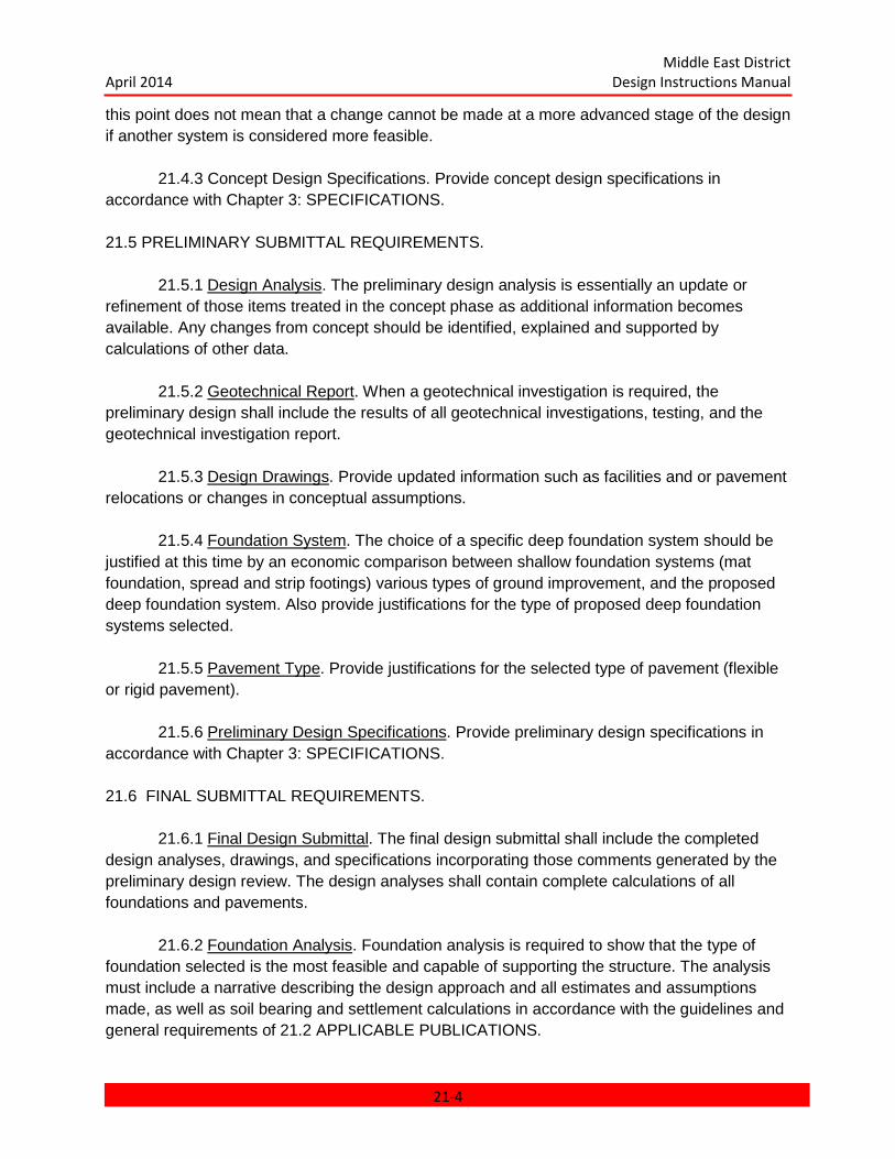
Middle East District April 2014 Design Instructions Manual
this point does not mean that a change cannot be made at a more advanced stage of the design if another system is considered more feasible.
21.4.3 Concept Design Specifications. Provide concept design specifications in accordance with Chapter 3: SPECIFICATIONS. 21.5 PRELIMINARY SUBMITTAL REQUIREMENTS.
21.5.1 Design Analysis. The preliminary design analysis is essentially an update or refinement of those items treated in the concept phase as additional information becomes available. Any changes from concept should be identified, explained and supported by calculations of other data.
21.5.2 Geotechnical Report. When a geotechnical investigation is required, the preliminary design shall include the results of all geotechnical investigations, testing, and the geotechnical investigation report.
21.5.3 Design Drawings. Provide updated information such as facilities and or pavement
relocations or changes in conceptual assumptions.
21.5.4 Foundation System. The choice of a specific deep foundation system should be justified at this time by an economic comparison between shallow foundation systems (mat foundation, spread and strip footings) various types of ground improvement, and the proposed deep foundation system. Also provide justifications for the type of proposed deep foundation systems selected.
21.5.5 Pavement Type. Provide justifications for the selected type of pavement (flexible or rigid pavement).
21.5.6 Preliminary Design Specifications. Provide preliminary design specifications in
accordance with Chapter 3: SPECIFICATIONS. 21.6 FINAL SUBMITTAL REQUIREMENTS.
21.6.1 Final Design Submittal. The final design submittal shall include the completed design analyses, drawings, and specifications incorporating those comments generated by the preliminary design review. The design analyses shall contain complete calculations of all foundations and pavements.
21.6.2 Foundation Analysis. Foundation analysis is required to show that the type of foundation selected is the most feasible and capable of supporting the structure. The analysis must include a narrative describing the design approach and all estimates and assumptions made, as well as soil bearing and settlement calculations in accordance with the guidelines and general requirements of 21.2 APPLICABLE PUBLICATIONS.
21-4

Middle East District April 2014 Design Instructions Manual
21.6.3 Final Design Specifications. Provide final design specifications in accordance with
Chapter 3: SPECIFICATIONS.
21.7 READY TO ADVERTISE (RTA) DESIGN REQUIREMENTS.
The comments generated during the final design review shall be incorporated in the documents before they are submitted as ready to advertise. 21.8 TECHNICAL REQUIREMENTS.
21.8.1 Geotechnical Design Specialist. Services of a Geotechnical Design Specialist will be required unless specifically waived by MED. Prior to the commencement of design work the name of the designated specialist along with the individual's educational background, experience, licenses and registrations shall be submitted for approval. The Geotechnical Specialist shall be a practicing registered professional Geotechnical Engineer, Engineering Geologist, or qualified Civil Engineer who has been practicing in geotechnical engineering field for a minimum of 10 years, etc., appropriate to the project. He shall be experienced, competent and specialized in soil mechanics, rock mechanics, subsurface investigations, interpretations, evaluations, ground water geology, rock excavation, hydrology, etc. The Geotechnical Design Specialist will be responsible for interpreting foundation investigation reports and reports of special geotechnical studies as well as designing various types of foundations, excavations, backfills, fills, dewatering systems, and other geotechnically related items. The Geotechnical Specialist shall present subsurface information in Design Reports, Contract Plans and Specifications.
21.8.2 Site Work. Discuss cut and fill recommendations. Relate foundation and pavement designs and excavation to utility layouts. Avoid excessive earth movement, and preserve natural site features where indicated.
21.8.3 Specifications. The applicable Unified Facilities Guide Specifications (UFGS) shall be edited by the A-E's geotechnical engineer/personnel. The edited specifications shall consider all geotechnical elements of the site. The edited specifications shall be coordinated between the drawings and design analyses.
21-5
Middle East District April 2014 Design Instructions Manual
CHAPTER 22 COMPUTER ASSISTED DESIGN AND DRAFTING
CHAPTER 22 COMPUTER ASSISTED DESIGN AND DRAFTING ...................................... 22-1 22.1 GENERAL ..................................................................................................................... 22-3
22.1.1 Intent ...................................................................................................................... 22-3 22.1.2 Standards for Data Presentation ............................................................................. 22-3 22.1.2 Software Compatibility ............................................................................................ 22-3
22.2 APPLICABLE PUBLICATIONS ..................................................................................... 22-3 22.3 GRAPHIC DATA FILES ................................................................................................ 22-3
22.3.1 File Naming Convention ......................................................................................... 22-3 22.3.2 Working Units ......................................................................................................... 22-4 22.3.3 Scale ...................................................................................................................... 22-4 22.3.4 Accuracy ................................................................................................................. 22-4 22.3.5 Text ........................................................................................................................ 22-5 22.3.6 Line Weights ........................................................................................................... 22-5 22.3.7 Line Style ................................................................................................................ 22-5 22.3.8 Line Colors ............................................................................................................. 22-5 22.3.9 Reference Files ...................................................................................................... 22-5 22.3.10 Level Assignments ................................................................................................ 22-6 22.3.11 Plotting ................................................................................................................. 22-6 22.3.12 File Documentation ............................................................................................... 22-6 22.3.13 Finalizing Design Files .......................................................................................... 22-7
22.4 NON-GRAPHIC DATA FILES ....................................................................................... 22-7 22.5 DIGITAL DATA EXCHANGE ......................................................................................... 22-7
22.5.1 Electronic Transfer.................................................................................................. 22-7 22.5.2 Media...................................................................................................................... 22-7 22.5.3 Demonstration of Compatibility ............................................................................... 22-8
22.6 CUSTOMIZATION. ....................................................................................................... 22-8 22.6.1 Standard Drawing Sheets ....................................................................................... 22-8 22.6.2 Cell Libraries ........................................................................................................... 22-8
22-1
Middle East District April 2014 Design Instructions Manual
LIST OF FIGURES Figure 1 – Cover Sheet File Information 22-17 Figure 2 – Index File Information 22-17 Figure 3 – Drawing Border/Title Block File Information 22-18 Figure 4 – Survey/Mapping Design File Information 22-19 Figure 5 – Civil Site Design File Information 22-20 Figure 6 – Sanitary Design file Information 22-21 Figure 7 – Building Background Design File Information 22-22 Figure 8 – Architectural Floor Plan Design File Information 22-23 Figure 9 – Architectural Elevations Design File Information 22-24 Figure 10 – Architectural Sections Design File Information 22-25 Figure 11 – Architectural Roof Plan Design File Information 22-26 Figure 12 – Architectural Reflected Ceiling Design File Information 22-27 Figure 13 – Architectural Furnishings Design File Information 22-28 Figure 14 – Architectural Details Design File Information 22-29 Figure 15 – Structural Design File Information 22-30 Figure 16 – Plumbing Design File Information 22-21 Figure 18 – Fire Protection Design File Information 22-32 Figure 19 – Electrical Site Design File Information 22-33 Figure 20 – Electrical Floor Plan Design File Information 22-34 Figure 21 – Electrical diagrams Design File Information 22-35 Figure 22 – Electrical Schedules Design File Information 22-36
22-2
Middle East District April 2014 Design Instructions Manual
CHAPTER 22 COMPUTER ASSISTED DESIGN AND DRAFTING
22.1 GENERAL.
22.1.1 Intent. Computer Assisted Design and Drafting (CADD) is required for all design projects. The CADD deliverables shall meet the requirements of this chapter, and the design shall otherwise meet the applicable requirements of this Manual.
22.1.2 Standards for Data Presentation. Unless specifically noted otherwise, the
standards for data presentation contained in Chapter 2: PRESENTATION OF DATA shall be used as the basis for the preparation of all design documents.
22.1.2 Software Compatibility. All digital data files shall be in the standard format used
by the software involved. Formats which can be read using built-in or third party translators are not considered a standard format of the software. The Architect-Engineer (A-E) shall ensure any translation or preprocessing necessary to reach the required compatibility, is complete and accurate. CADD files shall be fully operational within Bentley's MicroStation and Bentley Building. Related non-graphic files shall be suitable for use within the Microsoft Window environment; text files shall be provided in Microsoft Word; database files shall be provided for dBASE IV, version 1; and spreadsheet files shall be provided for Microsoft Excel. Adobe Acrobat Professional shall be used to create all PDF files.
22.2 APPLICABLE PUBLICATIONS. The current edition of the following publications form a part of this manual to the extent indicated by any references thereto:
Corps of Engineers Standard Manual for U.S. Army EM 1110-1-1807 Corps of Engineers Computer-Aided Design and Drafting (CADD) Systems.
American Institute CADD Layer Guidelines of Architects (AIA)
The CADD/GIS Technology Center: A/E/C CADD Standard
22.3 GRAPHIC DATA FILES. Unless otherwise indicated, graphic design files may be either two or three dimensional drawing files at the A-E's option. Graphic data scanned into CADD files must be functionally and operationally equivalent to vector data generated with commercial CADD software.
22.3.1 File Naming Convention. Each design file is to contain only one drawing and shall be uniquely named.
22.3.1.1 Design Drawing Files. Drawing files are to be named in the format
"AR100PNxx.DGN" where:
22-3
Middle East District April 2014 Design Instructions Manual
A: Discipline Designator R: Discipline Modifier 100: Sheet (drawing) Number (101, 102...) PN: Drawing Type Indicator xx: Used only for Amendments (01,02) or COPs (A,B) DGN: Design File Extension Discipline Designators and Modifiers are defined in the A/E/C CADD Standard and CAD Procedures Document. CAD Procedures will be provide for each project upon request to the MED CAD Manager, Joyce Rudy, [email protected] Drawings modified by an amendment or COP shall be generated by creating an archive copy of the unmodified file (ex.: AR101PN.DGN) and renaming the original so that it designates it as an amendment (ex.: AR01PN101.DGN) or a COP (ex.: AR101PNA.DGN).
22.3.1.2 Building Background Files. The building plan background files shall be named in the format “ARTNBKxx.DGN” where:
A: Discipline Designator R: Discipline Modifier T: Type of Drawing (P = Plan) N: Floor Level (0 = Ground, 1 = First, etc.) BK: Background File xx: Amendment (01, 02) or COP (A, B) DGN: Design File Extension These files are to be used as reference files in developing building plan drawings. 22.3.2 Working Units. Unless otherwise indicated, all work is to be done in metric units and will use the following working units:
MU = 1 meter SU = 1000 mm PU = 10
This is equivalent to 1 foot, 12 inches, and 254 positional units.
22.3.3 Scale. All graphics shall be created in actual (real world) size. Scaling of the Model into the sheet file will set the drawing scale. Size of text and other drawing symbols when placed must consider the anticipated scale of the plotted drawing so that the output will be in the proper proportion.
22.3.4 Accuracy. Graphic data in the design files shall be as accurate as the dimensions
given. For example, if the dimensions are shown in millimeters, then the digital data input must be accurate to the nearest millimeter.
22-4

Middle East District April 2014 Design Instructions Manual
22.3.5 Text. Text size and placement shall follow accepted drafting practices. Character construction shall be equivalent to MicroStation's standard fonts. All disciplines shall use text Font #1 (proportional font) for general purpose lettering and Font #3 (constant width) for tabular data. Where appropriate to the size of the text, Font #128 (Microsoft Windows Times Roman True Type Font) hatched should be used to create titles and other bold lettering. Where special fonts are approved for use, the font resource file shall include all fonts used in the project (including any fonts used as symbols) and shall be submitted with the graphic files. However, CAD standard fonts #1, #3 and #42 are reserved as standard, and shall not be replaced or renamed when special fonts are used. The font resource file shall be named XXX.rsc where "XXX" is the project number.
22.3.6 Line Weights. The use of line weights to construct details, sections, and text shall
follow accepted drafting practice. Variation in line weight is necessary to provide crisp, readable drawings and to avoid the "monotone" linework often encountered in automated work. To ensure a standard thickness for a given line weight, the line weights shall correspond to the following when plotted:
Line Weight Thickness Leroy Pen Number Inches Size 0 0.010 000 1 0.015 0 2 0.020 1 3 0.025 2 4 0.030 2.5 5 0.035 3
Line thickness shall increase 0.005 inch for each increase in line weight to a maximum weight of 31.
22.3.7 Line Style. The line styles shall be as follows: 0 – Solid 4 – Long Dash – Dot (Centerline) 1 – Dotted 5 – Short Dash 2 – Medium Dash 6 – Dash – Dot – Dot 3 – Long Dash 7 – Long Dash – Short Dash
22.3.8 Line Colors. Display colors shall be used to promote effective use of the CADD
system. They shall be assigned to aid the designer in developing and manipulating the design elements using the following color assignments:
0 – White 4 – Yellow 1 – Blue 5 – violet 2 – Green 6 - Orange 3 - Red
22.3.9 Reference Files. Middle East District (MED) references (overlays) certain design
files to other design files. The MicroStation CADD software accomplishes this by displaying multiple files simultaneously, while keeping the individual data sets separate so that the drawings can be manipulated independently. Referencing a single design file to several others allows repetitive elements to be duplicated rather than redrawn. In addition, all changes made to the reference file are automatically reflected in the active files to which they are referenced. The
22-5
Middle East District April 2014 Design Instructions Manual
ability to reduce drawing effort and to enhance design reliability are very desirable features. Reference files shall therefore be used as much as practical. To accommodate reference files, the following shall be provided as a minimum. 22.3.9.1 Registration of Drawings. Drawings of corresponding parts of the project must register when the drawings are used as reference files. For efficient referencing of drawing files, the corresponding plan drawings must occupy corresponding positions on the electronic drawing plane. For example, the lower left corner of the first floor plan must occupy the same coordinate location in its electronic drawing plan as does the lower left corner of the second floor plan in its electronic drawing plane. Not only must the structural, mechanical, and electrical building plans register one with another, but they also must register with the architectural plan drawings. Similarly, the site development plans and the site utility plans must also be registered among themselves as well as the site plan.
22.3.9.2 Border Sheet. Middle East District CADD projects use a common drawing border and title block for each project. This file shall be named SHEET.DGN. The project border and title block with "sheet independent" data is referenced to each drawing within the project. When a drawing file is created, "sheet dependent" title block data is added to the specific drawing file. The referencing must be such that the border is correctly positioned on the drawing file in order to display properly.
22.3.9.3 Floor Plan Elements. When drawing files are created for the mechanical, electrical, structural and other building plan drawings, they shall be developed without floor plan elements such as walls, doors, windows, stairs, toilet fixtures, and room names and numbers. In lieu of showing the floor plan elements on the mechanical, electrical, and structural plan drawings, these drawings will reference the building floor plan to provide this information. The plan drawing files must be configured to display the correct levels in the attached reference files.
22.3.9.4 Site Plan Elements. Similarly, when the civil, mechanical, and electrical site development plan drawings are created they shall be developed without site plan elements such as building footprints, roadway edges and centerlines, parking areas, sidewalks, ditches, ponds, and culverts. In lieu of showing the site plan elements, these drawings will reference the civil site plan to provide this information. The plan drawing files must be configured to display the correct levels in the attached reference files.
22.3.10 Level Assignments. Standardization of drawing level assignments is critical to the efficient use of the digital drawing data. To make digital design files consistent and manipulatable by MED and its customers, the A/E/C CADD Standard level will be used for all CAD work.
22.3.11 Plotting. Al Plotting shall be done one to one (1:1) without scaling. Design files shall be developed in anticipation of plotting on a monochrome, vector plotter. Raster data, filled areas and colored linework are not acceptable, unless otherwise approved.
22.3.12 File Documentation. Documentation shall be prepared for all design files to record the levels used and describe the data therein; to identify any attached reference files and their scaling and any relative movement; to identify requirements for non-standard font resource
22-6

Middle East District April 2014 Design Instructions Manual
files, pen tables, and color tables; and to record plotting requirements. See Figures 1 through 22 as examples. Submit file documentation with the design files in both hardcopy form and as digital text files. Hardcopy shall be bound as a single volume as indicated for the design analysis. Digital files shall be included with the graphic files on tape, and shall be named as the design file, but with a .DOC extension.
22.3.13 Finalizing Design Files. Before graphic design files are delivered, perform the following:
a. Remove all extraneous graphics outside the border. b. Compress to reduce all design files. c. Turn on all levels, both in reference files and in the active design file, which are to be
plotted to produce the final drawing. All non-plotted levels are to be turned off. d. Set the display with the complete drawing filling the complete screen in the sheet file. e. In the sheet file, set the system parameters appropriate to final plotting of the
drawing, i.e., set text display on, fast curve off, weight display on, etc. f. Save ("SAVE SETTINGS") the system parameters and display so the file will initially
come up in the above configuration. g. Include all files, both graphic and nongraphic, required for the project (i.e., color
tables, pen tables, font resource files, cell libraries, user command files, etc.). Standard MED and Microstation files need not be submitted.
h. Make sure that all support files such as those listed above are in the project directory and include configuration files and instruction for directory specification assignment.
i. Include any standard drawing sheets (i.e., abbreviation sheets, standard legend sheets, etc.) necessary for a complete project.
j. Document any non-standard fonts, tables, etc. k. Detach all unused reference files from the drawings.
22.4 NON-GRAPHIC DATA FILES. Graphic elements can contain linkages to non-graphic database information. Such attributes and their associated databases are not required. 22.5 DIGITAL DATA EXCHANGE.
22.5.1 Electronic Transfer. With approval by MED, the exchange of digital data may occur via the Internet, ProjectWise or by e-mail. Documentation shall accompany the file transfer in the format of a single Microsoft Word file, which describes and lists the files which are being transferred. A PDF file of all the drawings transferred shall be provided as well. Additionally, any compression/decompression utilities used must be documented and accompany the transferred files.
22.5.2 Media. The acceptable media for exchange is CD-ROM/DVD ROM. The medium shall become the property of the Government on completion of work.
22.5.2.1 The external label for any CD/DVD submitted to MED shall identify as a minimum:
22-7
Middle East District April 2014 Design Instructions Manual
a. The date of creation b. Project name and number c. A short description of the contents
A transmittal sheet containing the above information and the file names on each CD/DVD shall accompany the CD/DVD. The media shall become the property of the Government on completion of work.
22.5.3 Demonstration of Compatibility. A sample drawing shall be furnished as a test not later than 30 calendar days following contract award to demonstrate full compatibility with the described CADD system. The sample drawing will be returned to the A-E upon satisfactory completion of the test.
22.6 CUSTOMIZATION. MED has created the following custom features within the CAD environment to promote the
effective use of CADD. These elements are available to A-E firms preparing design files in CAD according to this Chapter. 22.6.1 Standard Drawing Sheets.
22.6.1.1 COVER.DGN Generic volume cover sheet according to Chapter 2: PRESENTATION OF DATA, Figure 2-3.
22.6.1.2 INDEX.DGN Generic volume index sheet according to Chapter 2: PRESENTATION OF DATA, Figures 2-4, 2-6, 2-7A, and 2-7B.
22.6.1.3 SHEET.DGN Generic drawing border and title block according to Chapter 2: PRESENTATION OF DATA, Figures 23, 2-5, 2-6b, 2-7A, 2-7B and 2-8A. The "SUBMITTED BY" area in the title block as shown in Figures 2-7A and 2-7B, is to contain the name and title of the discipline manager or equivalent. 22.6.2 Cell Libraries.
22.6.2.1 GENERAL.CEL is a library containing graphic scales (See Chapter 2, Figure 2-14), north arrow (See Chapter 2, Figure 2-15), cross reference symbols (See Chapter 2, Figure 2-16), reference symbols (See Chapter 2, Figure 2-17), Corps logo, arrow head and other general drafting symbols.
22-8
Middle East District April 2014 Design Instructions Manual
CHAPTER 23 STANDARD PROCEDURES FOR DESIGN OF MINOR PROJECTS
CHAPTER 23 STANDARD PROCEDURES FOR DESIGN OF MINOR PROJECTS ............ 23-1 23.1 INTRODUCTION ........................................................................................................... 23-2
23.1.1 General ................................................................................................................... 23-2 23.1.2 Purpose .................................................................................................................. 23-2
23.2 PLANNING AND IMPLEMENTATION ........................................................................... 23-2 23.2.1 Planning ................................................................................................................. 23-2 23.2.2 Implementation ....................................................................................................... 23-3
23.3 DESIGN APPROACH ................................................................................................... 23-3 23.3.1 Architectural............................................................................................................ 23-3 23.3.2 Civil ........................................................................................................................ 23-3 23.3.3 Structural ................................................................................................................ 23-3 23.3.4 Fire Protection ........................................................................................................ 23-3 23.3.5 Heating, Ventilating & Air-Conditioning ................................................................... 23-3 23.3.6 Plumbing ................................................................................................................ 23-4 23.3.7 Electrical ................................................................................................................. 23-4
Chapter 24 23.4 CONTRACT DOCUMENTS ........................................................................ 24-4 23.4.1 Drawings ................................................................................................................ 24-4 23.4.2 Specifications ......................................................................................................... 24-4 23.4.3 Design Analysis ...................................................................................................... 24-5
23.5 COST ESTIMATE ......................................................................................................... 24-5 23.5.1 General ................................................................................................................... 24-5
23.6 PROJECT SCHEDULE ................................................................................................. 24-5 23.6.1 General ................................................................................................................... 24-5
23.7 SURVEYS, INVESTIGATIONS AND STUDIES............................................................. 24-6 23.7.1 General ................................................................................................................... 24-6 23.7.2 Geotechnical ........................................................................................................... 24-6 23.7.3 Topographic Mapping Survey ................................................................................. 24-6 23.7.4 Contractor Site Visit ................................................................................................ 24-6
23-1
Middle East District April 2014 Design Instructions Manual
CHAPTER 23
STANDARD PROCEDURES FOR DESIGN OF MINOR PROJECTS
23.1 INTRODUCTION
23.1.1 General. Minor projects, such as those involving simple designs for installation support or relatively small projects shall be considered for Minor Project Design (MPD) procedures. For such projects a streamlined approach to design, resulting in construction documents similar to commercial documents, may be used. Streamlined procedures apply to activities within many offices including Project Management, Contracting, Office of Counsel, etc.; however, this chapter focuses only on activities which are the direct responsibility of the U.S. Army Corps of Engineers, Middle East District (CETAM), Engineering Division (CETAM-EN) design team, Architect Engineer (A-E) firms, and other design elements preparing design for Corps of Engineers, Middle East District.
23.1.2 Purpose. The purpose of utilizing MPD procedures is to shorten design time, save design cost and facilitate reproduction of design documents while assuring that designs adequately describe the work for the construction contractor.
23.2 PLANNING AND IMPLEMENTATION
23.2.1 Planning. The suitability of the MPD process for a particular project must be evaluated on a case by case basis. Not all projects are appropriate for streamlined procedures, particularly those which are large, complex, or nonstandard, and those involving renovation of existing facilities. Also projects which require input from organizations or agencies other than CETAM, or the immediate customer (e.g. U.S. Army Corps of Engineers (USACE) centers of expertise), may not be good candidates for MPD.
23.2.1.1 The risk associated with utilizing MPD procedures on a given project must be identified during the planning phase of the project and steps must be taken to minimize that risk. By showing fewer details and simplifying specifications, the possibility of omissions and unintentional errors is increased. On relatively simple projects this risk is small. On larger, more complex projects, this risk can be significantly greater. The goal of the MPD procedure is to identify projects for which the risk is acceptable and savings in time and design cost will not adversely affect the construction product. Designers must be mindful of the fact that customers desire the shortest and least costly design effort consistent with producing quality construction products. Overly conservative decisions on design methodology will, in the long run, dissatisfy CETAM’s customers.
23.2.1.2 Potential roadblocks to the MPD process, such as environmental or physical security issues, must be identified as early as possible. Project funding and schedule constraints must be considered to insure that a project is a true candidate for MPD. Customer input should be solicited through the Project Manager. The project scope must be clearly
23-2

Middle East District April 2014 Design Instructions Manual
defined, or obtained, utilizing available data such as as-built drawings, shop drawing submittals, O&M manuals, survey reports, conference/meeting minutes and photographs, etc.
23.2.1.3 The determination of the method of design, whether full design, MPD, Design/Build or a combination of these, will be made by the Chief, CETAM-EN in coordination with the project team and the customer.
23.2.2 Implementation. The MPD project design team consisting of representatives from each technical design discipline shall be established. A Design Team Leader responsible for coordination between team members and verifying all external requirements with the PM shall be appointed. Balance between simplicity and quality must be maintained. Care must be taken not to shift undue risk to the construction contractor. Designers shall use common, three part specification format, and common standards for sketches and drawings within each design package. Although a variety of presentation methods and presentation media are used, there should be uniformity in title blocks, font sizes, etc.
23.3 DESIGN APPROACH
Considerations by discipline follow:
23.3.1 Architectural. Consider developing only two building elevations rather than four; one building section rather than two. A roof plan may be deemed unnecessary. The number of wall sections may be reduced. Evaluate the need for a reflected ceiling plan, etc. Minimize the use of design details and/or standard detail drawing sheets to the greatest extent possible.
23.3.2 Civil. Evaluate using more new spot elevations on the grading plan rather than developing some, or all of the new contouring required. Evaluate utilizing horizontal road alignment control and a typical road cross-section rather than developing separate drawings for plan and profile of roads. Consider developing a rigid pavement joint layout detail rather than providing joint layouts for all rigid pavement in the project. Require the contractor to submit joint layout plans for approval. Consider deleting some details and require the contractor to use manufacturers recommendations (i.e. fence details, water valve details, fire hydrant details, etc.), or to match existing features at the site (i.e. curbs, sidewalks, etc.).
23.3.3 Structural. Utilize a combined foundation/floor plan and maximize the use of standard drawings. Consider using a single size and type of spread footing, column and beam where economical.
23.3.4 Fire Protection. Coordinate the location of building section(s) with the Architect so that the Architectural sections can be utilized for sprinkler system. Use standard details to the maximum extent possible.
23.3.5 Heating, Ventilating & Air-Conditioning. Show ductwork in single line format. Evaluate the need for section(s) through mechanical rooms. Only the congested mechanical equipment rooms with very complex duct routing may need sections. Air flow diagrams are not required. Evaluate the need for diffuser, register, grille schedule vs. providing information for each outlet on the floor plan. Abbreviations and legend should be reduced to a minimum. Use
23-3

Middle East District April 2014 Design Instructions Manual
standard details to the maximum extent possible. Usage of enlarged floor plans (scales: 1:50 or larger) should be minimized. Include mechanical equipment schedules.
23.3.6 Plumbing. Evaluate whether riser diagrams are necessary to clarify routing and sizes of drain, water and vent piping. Minimize the use of abbreviations and legend. Standard details should be used to the maximum extent possible. Usage of enlarged floor plans (scales: 1:50 or larger) should be minimized. Include equipment schedules for fixtures, pumps and water heaters.
23.3.7 Electrical. Major items such as switchgear, switchboards, transformers, generators, etc. must be clearly shown both schematically and in plan as should unusual components such as UPS systems, frequency converters, etc. One line diagrams should show feeder size and panelboard ratings and plan drawings should show panelboard locations and location of power for the service. One line diagrams for fire alarm, security, and telephone systems shall be shown. Plan locations for communication systems outlets are also needed. Lighting fixture locations and types must be identified. Switching locations and schemes should also be shown, especially where three-way switching schemes are needed. Power outlets, phone and data outlets, fire alarm initiating devices and alarms, and security system devices should be shown on the plans. Special circuit requirements for mechanical or specialized equipment should be clearly defined. Details such as specific branch circuit groupings could be left to the discretion of the contractor.
CHAPTER 24 23.4 CONTRACT DOCUMENTS
23.4.1 Drawings. Use of 8.5" X 11" and 11" X 17" sheet sizes shall be maximized to facilitate simple reproduction and faxing of drawings. Larger drawings may be used as necessary on an exception basis. Consideration should be given to developing schedules (door, window, finish, panel, louver, etc.) within word processing software for insertion into specifications rather than placement on drawings, if savings can be realized. Care should be taken to insure that the minimum text size on drawing sheets is in accordance with applicable CADD standards. Use of digital photographs on drawings should be included where possible to document existing conditions, particularly on renovation projects where demolition is involved. It is recommended that an identifier be developed, possibly integral within the sheet border, to differentiate MPD projects from those developed using conventional design procedures. Use notes on drawing sheets to identify work required as a supplement to, or replacement for, specification sections when possible.
23.4.2 Specifications. On very simple projects, through the use of notes on drawings and sketches, specifications may not be required. When specifications are needed, the 3-part format utilized in the Corps of Engineers Guide Specifications (CEGS) shall be used for familiarity and clarity. The minimum effort should be expended in the development of specifications. Local materials should be utilized as much as practicable. Local standards should be referenced where possible, in keeping with the overall intent of abbreviated design schedules. The requirements for contractor submittals shall be carefully evaluated. In general, the use of
24-4
Middle East District April 2014 Design Instructions Manual
submittals should be minimized and when used, the requirement for government approval should be minimized. Submittals shall be requested only where those items are essential, or where details normally done by the designer have been “deferred” to the shop drawing stage. When the use of brand-name is considered for specifying products or equipment, the following must be complied with; Brand-name or equal descriptions, and other purchase descriptions that permit prospective contractors to offer products other than those specifically referenced by brand name, shall provide for full and open competition and do not require justifications and approvals to support their use. However, the Specifier must meet the requirements of FAR 11.0002, and Subpart 6.300, 6.301, 6.302 and 6.302-1. A submittal register is required and shall be developed with the MPD objectives in mind. Rely on shop drawings to work out specific details.
23.4.3 Design Analysis. As with any conventionally designed project, a design analysis is required as a means of documenting significant design assumptions and elements not shown in the contract documents, for future use. It will also contain any design calculations associated with the project. The MPD design analysis format shall be an abbreviated version of the format currently utilized for a conventionally designed project. Each design discipline shall make the determination of what information is appropriate for the design analysis. The use of design checklists within each design discipline is encouraged to address repetitive type issues. Use of existing documents such as copies of electronic messages as a means of documenting project evolution or clarifying project scope should be maximized. Photographs may be included in the project design analysis.
23.5 COST ESTIMATE 23.5.1 General. Development of the cost estimate should reflect the simplicity of the
design. Use of “rule of thumb” data by cost engineers is encouraged by Headquarters U.S. Army Corps of Engineers (HQUSACE) as a means of checking adequacy of funding. Use of cost per square foot pricing may be required to prepare government estimates due to limitations in available design funds and brevity of project design schedules.
23.6 PROJECT SCHEDULE
23.6.1 General. A project schedule template tailored for use with MPD projects shall be used. Utilization of electronic transfer of contract documentation to the customer and other agencies for design reviews should be utilized, where possible, to eliminate shipping time. It is imperative that project scopes, facility locations, design/functional intent and funding are identified early in the project development to allow for adequate geotechnical investigations and engineering. Schedules and budgets must be established in concert with the geotechnical and site specific requirements for each project.
24-5

Middle East District April 2014 Design Instructions Manual
23.7 SURVEYS, INVESTIGATIONS AND STUDIES
23.7.1 General. Field surveys, geotechnical investigations and development of topographic mapping are long lead items which are critical to development of siting, grading, foundation and utility designs. Consequently, funding requests, scope-of-work and procurement actions must be initiated early to prevent project delay.
23.7.2 Geotechnical. Site-specific geotechnical field and laboratory data and engineering design parameters shall be developed by MED. Each project shall be examined by Structural/Geotechnical Branch, CETAM-EC-TG for ways to economize without compromising technical judgment and quality.
23.7.3 Topographic Mapping Survey. Accurate topographic mapping shall be developed or procured using in-house resources. At each site, a minimum of four permanent benchmarks shall be established outside the proposed construction areas. The horizontal and vertical control will be tied to the local recognized coordinate system. Mapping products shall be delivered to Civil Branch, CETAM-EN-C in hard copy and in digital format, compatible with Microstation. The scale of mapping and contour interval necessary for each project shall be evaluated to determine if less than conventional mapping detail would be suitable.
23.7.4 Contractor Site Visit. Evaluate placing more responsibility on the contractor to collect information during the site visit, thereby reducing the design effort required with respect to developing demolition plans and site conditions.
24-6

Middle East District April 2014 Design Instructions Manual
CHAPTER 24 COST CONTROL DURING DESIGN (DESIGN-TO-COST)
CHAPTER 24 COST CONTROL DURING DESIGN (Design-to-Cost) .................................. 24-1 24.1 GENERAL ..................................................................................................................... 24-2 24.2 REFERENCES.............................................................................................................. 24-2 24.3 COST CONTROL DURING DESIGN ............................................................................ 24-2 24.4 COST CONTROL PROCESS ....................................................................................... 24-3
24.4.1 Project Definition (PD) Phase ................................................................................. 24-3 24.4.2 Design Phase ......................................................................................................... 24-3
APPENDIX A ........................................................................................................................ 24-5 Parametric Cost Estimate .................................................................................................. 24-5 Parametric Cost Estimate Wbs System Construction Cost Report ..................................... 24-6 Abbreviations ..................................................................................................................... 24-7
24-1

Middle East District April 2014 Design Instructions Manual
CHAPTER 24 COST CONTROL DURING DESIGN
(Design-to-Cost) 24.1 GENERAL.
The intent of this chapter is to provide policy and guidance to the design disciplines of the Middle East District (MED) for all MED projects in order to control cost during design. Cost Control During Design is established to place more emphasis on accurate definition of project requirements, preparation of a parametric cost estimate (or equivalent) to establish cost targets based on these requirements and monitoring during the design. Each designer is responsible to assure construction costs remain within budget. When cost increases are caused by customer directed scope changes the design team must take immediate action to identify the impact and advise the Project Manager
24.2 REFERENCES.
a. Project DD Form 1391, Military Construction Project when applicable, in lieu of Foreign Military Sales (FMS).
b. Architectural and Engineering Instruction (AEI), Project Engineering with Parametric Estimating.
c. MED Design Manual for Military Construction (MILCON) and FMS Projects. d. Corps of Engineers Guide Specification (CEGS). e. Corps of Engineers Cost Engineering Regulations and Manuals. f. Federal Acquisition Regulation (FAR). g. All MILCON and FMS established criteria. h. Architectural and Engineering Instructions for Cost Control During Design, 19 Dec 96,
Headquarters U.S. Army Corps of Engineers (HQUSACE).
24.3 COST CONTROL DURING DESIGN.
a. Cost control during design is a process of identifying the full scope of a project and establishing cost targets before design starts to effect cost control throughout the course of design. This scope must be identified and verified with the user. Cost targets are identified using a system level work breakdown structure for every system (for both primary buildings and support facilities) being designed into the project. These system level cost targets are estimated using parametric cost estimating systems (and other detail methods for unique work) and adjusted where necessary so that the full scope is included in the total cost. The parametric cost estimates when approved by the Division Chief, customer, and Project Manager (PM) will then become the basis for establishing cost targets for the discipline designers responsible for those system designs.
b. The accuracy and reasonableness of the project (parametric) estimate is highly dependent on the input of the design team and it's customers. Therefore, it should be developed based on the most complete requirements available. The estimate will be carefully reviewed by the design team to ensure that each system cost target is
24-2

Middle East District April 2014 Design Instructions Manual
reasonable and that all the systems included within the estimate will accomplish all design requirements of the project. This will be a topic at design team meetings.
c. Designers must communicate constantly with the cost engineer/estimator and inform the cost engineer/estimator of all design decisions and changes affecting the cost. The cost engineer/estimator must maintain the up-to-date estimate to ensure that it stays current with the design. If the current estimate deviates from the target by greater than 5%, the cost engineer/estimator must call attention to and immediately advise the designer(s) about the cost variations. With this process the designers will have awareness of the cost impacts of their decisions and they will be more cost conscious. Key cost review milestones are identified during the process to ensure that the design proceeds on cost, schedule, and design target.
24.4 COST CONTROL PROCESS.
24.4.1 Project Definition (PD) Phase
1) The customer/user defines the total requirements for the project during the programming and project definition phases in order to minimize user changes during design.
2) The PD phase requires the preparation of a parametric estimate or equivalent using either of the two Department of Defense (DOD) systems, the Air Force Parametric Cost Estimating System (PACES) or Tri-Services Automated Cost Engineering System (TRACES) Parametric Building Models for Windows (PBMW). Estimate must be prepared to the systems level as shown in Appendix A.
3) The design team must then verify the cost estimates to ensure that there is clear agreement and understanding on scope and a commitment on the cost targets. If the scope and cost targets do not match, all conflicts must be resolved prior to proceeding with design.
24.4.2 Design Phase
1) The design schedule (as developed by the design team) will identify the phases at which revised estimates will be required. Updated estimates using the breakdown shown in Appendix A will be developed and distributed to the design team.
2) If cost targets are being met, design continues. 3) When the cost target at any system level is exceeded, the design discipline with
assistance from Cost Engineering must identify the reasons for the overrun. The designer must review system components to identify if changes can be made to remain with the target estimate. If a cost increase must be made, the design team must advise the Design Team Leader and Project Manager who in turn must advise the customer of the reasons for increase, their construction costs, design costs, and schedule impacts. Options to the proposed design that would mitigate cost and schedule impacts will be identified. All decisions at this point must be based on agreement between the customer and MED.
24-3

Middle East District April 2014 Design Instructions Manual
4) At the Ready to Advertise (RTA) design review, a cost estimate review must be made prior to proceeding to final Request For Proposal (RFP) documents and formal solicitation.
5) Once cost and design issues have been resolved, the design will proceed to RFP. The Government Estimate (GE) is prepared and the project advertised. The estimate is expected to be complete at this stage except for quotation, bid period discoveries, and amendment impacts.
24-4

Middle East District April 2014 Design Instructions Manual
APPENDIX A
PARAMETRIC COST ESTIMATE DATE: 11/26/1996 TIME: 08:21:38
PROJECT: CC1996
PROJECT DESCRIPTION: General Purpose Administration Building
PROJECT COMMENT: This is a parametric cost estimate for cost control during design.
BUILDING TOTAL GROSS FLOOR AREA: 25,000 SF GEOLOCATION: ANDREWS AFB ESTIMATED BY: USACE ESTIMATE DATE: 11/20/1996 REPORT FILE: psyscc96.wpd COST DATABASE: NAT95A ESCALATION MODIFIER: Mid-Point of Construction
24-5
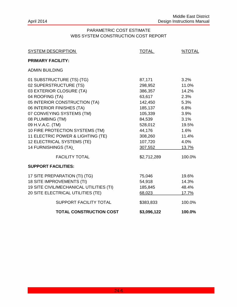
Middle East District April 2014 Design Instructions Manual
PARAMETRIC COST ESTIMATE WBS SYSTEM CONSTRUCTION COST REPORT
SYSTEM DESCRIPTION TOTAL %TOTAL
PRIMARY FACILITY:
ADMIN BUILDING
01 SUBSTRUCTURE (TS) (TG) 87,171 3.2% 02 SUPERSTRUCTURE (TS) 298,952 11.0% 03 EXTERIOR CLOSURE (TA) 386,357 14.2% 04 ROOFING (TA) 63,617 2.3% 05 INTERIOR CONSTRUCTION (TA) 142,450 5.3% 06 INTERIOR FINISHES (TA) 185,137 6.8% 07 CONVEYING SYSTEMS (TM) 105,339 3.9% 08 PLUMBING (TM) 84,539 3.1% 09 H.V.A.C. (TM) 528,012 19.5% 10 FIRE PROTECTION SYSTEMS (TM) 44,176 1.6% 11 ELECTRIC POWER & LIGHTING (TE) 308,260 11.4% 12 ELECTRICAL SYSTEMS (TE) 107,720 4.0% 14 FURNISHINGS (TA) 307,552 13.7%
FACILITY TOTAL $2,712,289 100.0%
SUPPORT FACILITIES:
17 SITE PREPARATION (TI) (TG) 75,046 19.6% 18 SITE IMPROVEMENTS (TI) 54,918 14.3% 19 SITE CIVIL/MECHANICAL UTILITIES (TI) 185,845 48.4% 20 SITE ELECTRICAL UTILITIES (TE) 68,023 17.7%
SUPPORT FACILITY TOTAL $383,833 100.0%
TOTAL CONSTRUCTION COST $3,096,122 100.0%
24-6

Middle East District April 2014 Design Instructions Manual
Abbreviations:
TA – Architectural TM –Mechanical
TI –Civil TE –Electrical
TS –Structural TG –Geotechnical
* * * * *
24-7

Middle East District April 2014 Design Instructions Manual
CHAPTER 25 DESIGN PROCEDURES FOR PROTECTION OF U.S. FORCES
CHAPTER 25 DESIGN PROCEDURES FOR PROTECTION OF U.S. FORCES ................. 25-1 25.1 INTRODUCTION ........................................................................................................... 25-2 25.2 BACKGROUND ............................................................................................................ 25-2
25.2.1 Point of Contact ...................................................................................................... 25-2 25.2.2 Designs .................................................................................................................. 25-2 25.2.3 Standards ............................................................................................................... 25-2
25.4 WAIVERS ..................................................................................................................... 25-3 25.5 GENERAL GUIDANCE ................................................................................................. 25-3
25.5.1 Threat Analysis ....................................................................................................... 25-3 25.5.2 Security requirements. ............................................................................................ 25-4
25.6 DISCIPLINE GUIDANCE .............................................................................................. 25-4 25.6.1 General ................................................................................................................... 25-4 25.6.2 Aspects Of Force Protection Design. ...................................................................... 25-4
25-1
Middle East District April 2014 Design Instructions Manual
CHAPTER 25
DESIGN PROCEDURES FOR PROTECTION OF U.S FORCES
25.1 INTRODUCTION.
Terrorists are more knowledgeable, well-organized, well-financed and more of an international threat than ever before. Because America’s conventional fighting capabilities are so strong, organizations that wish to confront the United States (U.S.), choose terrorism. Our military must be better prepared to protect themselves, therefore, force protection efforts are the top priority of U.S. military leaders at every level around the world. The U.S. military must be the world’s foremost experts on force protection.
25.2 BACKGROUND.
The procedures outlined in this chapter provide for the minimum force protection physical standards that must be incorporated into new construction, in all locations controlled or used by U.S. Forces in Middle East District’s (MED) area of responsibility (AOR). Also provided are waiver criteria and guidance for upgrading existing structures. Refer to reference; USCENTCOM classified (secret) document, for additional standards for temporary, existing, and rehabbed structures.
25.2.1 Point of Contact. MED is the primary construction agent for the design of facilities in our AOR. MED will coordinate force protection engineering and design with the U.S. Army Corps of Engineers’ Protective Design Center in Omaha, Nebraska, and other centers of expertise.
25.2.2 Designs. All designs for U.S. service components will incorporate design features into new construction that minimize the risk to personnel from terrorist attacks without unnecessarily restricting operations. Implementation of standards or requests for waiver are the responsibility of the Central Command (CENTCOM) service components.
25.2.3 Standards. Except where specific standards are provided, structures will be designed to survive well enough to allow people inside the building to get out; however, the structure may not be useable. The intent is to provide protection without a bunker mentality.
25.3 REFERENCES
a. TM5-853-1/AFMAN 32-1071 - Security Engineering.
b. TM5-853-2/AFMAN 32-1071 - Security Engineering Concept Design.
c. TM5-853-3/AFMAN 32-1071 - Security Engineering Final Design.
d. Army Regulation (AR) 1901-51, Minimum Security Requirements for Army Supplies and Equipment.
e. FM 19-30, Physical Security Evaluations with update.
25-2
Middle East District April 2014 Design Instructions Manual
f. DOD Manual 0-2000.12-H, Protection of DOD Personnel and Activities against acts of terrorism and political turbulence. Policies, guidance and mandatory. standards.
g. USCENTCOM classified (secret) document, Appendix 2 to Annex C to USCINCCENT OPORD 97-01 (u) Construction Standards.
h. DOD Manual 5220-22-M, Design of Storage Vaults and Strongrooms.
i. ETL 1110-7-1, Bullet and Force Entry Resistant Window Design.
j. US Dept of State, Bureau of Diplomatic Security, Physical Security Handbook 12 FAH 5 (April 95).
k. TM 5-855-1, Fundamentals for Protective Design for Conventional Weapons, 3 Nov 86.
l. USACE Memorandum, CEMRO-ED-ST (415-10f), 6 Mar 97, (NOTAL) (secret).
25.4 WAIVERS.
A service component may request a waiver of an otherwise applicable standard only if compliance with the standard at a particular installation or facility would seriously impair its actions, adversely affect relations with the host nation, or would require substantial expenditure of funds at an installation that forces will be relocated from in the near future. A request for waiver will:
a. Identify the particular standard for which a waiver is requested.
b. Describe the extent of the relief requested and the period the waiver will be in effect.
c. Describe the anticipated impact of the waiver, if any, on the safety of U.S. forces over the period of the waiver.
d. Describe the justification for the waiver and if a complete waiver of the standard is requested, why a partial and/or temporary deviation would not be sufficient.
e. Where applicable, describe attempts to comply with standards that have been prevented by host nation officials.
f. Provide an engineer analysis to support mitigating measures installed in lieu of strict compliance with the stated standard, its cost, and estimated completion date.
Refer to reference; USCENTCOM classified (secret) document, for definitions of structures.
25.5 GENERAL GUIDANCE.
25.5.1 Threat Analysis. Typically the customer conducts, or causes to be conducted, a threat analysis for the project to be designed and constructed. The threat analysis is used to create a physical and electronic security report which defines protective measures required and recommended. The threat analysis shall be reviewed by the U.S. Army Corps of Engineers
25-3
Middle East District April 2014 Design Instructions Manual
(USACE) Protective Design Center (PDC), Omaha, Nebraska. The PDC will also review and comment on the design at selected stages. It should be noted that the threat level will likely change during the operational life of a facility and should be periodically reviewed.
25.5.2 Security requirements. Security requirements shall be outlined in the 1391 for military construction (MILCON) projects and detailed in planning and program (P&P) reports. For foreign military sales (FMS) work, force protection requirements will be determined by close coordination and discussions with the customer.
25.5.2.1 Once force protection requirements are defined, the following steps shall be taken:
a. Currently the primary document for force protection standards and requirements for all CENTCOM work is reference; USCENTCOM classified (secret) document. Review of this document should be the first step in planning your design approach to each project.
b. Determine if standard designs are available which meet the identified force protection requirements.
c. If standard designs are not available, determine whether written guidance or in-house expertise exists sufficient to accomplish the required security design.
d. Identify sources of outside assistance if required.
e. Contact the PDC MCX early in the design process for assistance and guidance. For MCA projects, the PDC MCX must review DD Forms 1391 before certification.
25.6 DISCIPLINE GUIDANCE.
25.6.1 General. Stand-off distances, topography, and other site factors should be identified early in the planning and design process since they can define the effectiveness of the weapon or weapons to be protected against (i.e. direct fire, indirect fire, etc.). The blast and fragmentation effects from the weapons determine the design parameters for building construction for inhabited, billeting and primary gathering structures.
25.6.2 Aspects Of Force Protection Design. Aspects of force protection design will include but not be limited to consideration of the following criteria:
a. Civil. Standoff Distances, Perimeter Fencing (reinforced), Ditches and Berms, Abandonment of Facilities, Interior Fencing, Guard Towers, Entry Control Points to include barriers, beams, reinforcing, etc., Perimeter Blast Walls/revetments and barriers, Guard Railing, Alterations /to, or new construction of, roadways and parking areas, Topography
b. Geotechnical. Site Excavation Characteristics, Materials for Berm Construction, Suitable materials for concrete, road, parking area, asphalt, etc., Suitable foundations for site conditions, soil and rock conditions and characteristics
c. Architectural. Window Materials, Window Guards, Shatter Resistant Film, Exterior
25-4
Middle East District April 2014 Design Instructions Manual
Penetration Sizing, Special Doors, Special Locks, Special Security Door Hardware (cipher locks, etc.), Personnel Shelters, Building Anchorage, Entry Control Points
d. Structural. Blast Protective Construction, Personnel Bunkers
e. Electrical. Perimeter and other Security Lighting, Warning Systems, Backupgenerators, Power and Fuel Distribution to Facilities, Entry Control Points, Guard Towers, etc., Interior Emergency Lighting, IDS (intrusion detection system), Communications System
f. Mechanical. Penetrations to outside adequately secured (bars, etc.), Entry Control Point, Guard Towers
g. Fire Protection. Fire Extinguishers/Fire Suppression Systems in accordance with codes and standards
25-5