midas Civil 2006 (V7.6.1) Enhancements - CSPFea
26
midas Civil 2006 (V7.6.1) Enhancements April, 2009 Analysis • Automatic Check for Tendon Stress Limits • Addition of Cable Efficiency Table • Addition of Time Dependent Material (Creep/Shrinkage, Compressive Strength and Tendon Loss) as per Eurocode2:04 • Addition of the Time Dependent Material (Compressive Strength) as per CEB-FIP (1978) • Update on Time Dependent Material (Creep/Shrinkage, Compressive Strength and Tendon Loss) as per IRC:18-2000 • Improvements of the Moving Load Analysis as per IRC: 6-2000 • Addition of distributed springs • Addition of Sturm Sequence Check and Load Factor Range option in Buckling analysis • Improvements on the Eigenvalue analysis considering the maximum number of frequencies • Transfer reactions of slave nodes to the master node • Considering buckling load in the Pushover Yield Surface • Option for ignoring Lateral-Torsional Buckling mode in Buckling Analysis • Finding Concurrent Forces in Moving Load Analysis as per BS5400 • Nonlinear Point Spring Supports for Construction Stage Analysis
Transcript of midas Civil 2006 (V7.6.1) Enhancements - CSPFea

midas Civil 2006 (V7.6.1) Enhancements
April, 2009
Analysis
• Automatic Check for Tendon Stress Limits
• Addition of Cable Efficiency Table
• Addition of Time Dependent Material (Creep/Shrinkage, Compressive Strength and Tendon Loss) as per Eurocode2:04
• Addition of the Time Dependent Material (Compressive Strength) as per CEB-FIP (1978)
• Update on Time Dependent Material (Creep/Shrinkage, Compressive Strength and Tendon Loss) as per IRC:18-2000
• Improvements of the Moving Load Analysis as per IRC: 6-2000
• Addition of distributed springs
• Addition of Sturm Sequence Check and Load Factor Range option in Buckling analysis
• Improvements on the Eigenvalue analysis considering the maximum number of frequencies
• Transfer reactions of slave nodes to the master node
• Considering buckling load in the Pushover Yield Surface
• Option for ignoring Lateral-Torsional Buckling mode in Buckling Analysis
• Finding Concurrent Forces in Moving Load Analysis as per BS5400
• Nonlinear Point Spring Supports for Construction Stage Analysis

midas Civil 2006 (V7.6.1) Enhancements
April, 2009
Pre/Post-Processing
• Importing Composite Sections generated from SPC
• Improvements on the display of Supports and Point Spring Supports
• Addition of the Preference in online help
• Addition of upside-down T-shape beam
• Improvements in IS84 section DB
• Save an image in JPG format
• Addition of an export option in result tables
• Export frame model to solid/plate model
• Improvements in Beam Wizard

MIDAS Civil Integrated Solution SystemFor Bridge and Civil Structure 2009 Upgrade
3/26
Results > Result Tables > Tendon > Tendon Stress Limit Check
• In the Tendon Stress Limit Check table, the stresses in tendons, and the stress limits at the anchorages and elsewhere along the length of the
member are displayed. If the stress in a tendon exceeds the stress limit, the corresponding row is marked in red.
• When numerous tendons exist in a model file, this function is very convenient in checking the stress limits in a spreadsheet table format.
Effects & Usage
• The program checks stresses in tendons based on the stress limits specified by the user.
Upgrade Contents
Automatic Check for Tendon Stress Limits
[Tendon Stress Limit Check Table]

MIDAS Civil Integrated Solution SystemFor Bridge and Civil Structure 2009 Upgrade
4/26
Results> Result Tables > Cable Efficiency
mod( ) ( )c cEA r E A
2 5 3
1
1 cos /12c c
rG E A H
Cable efficiency, r, is calculated from the following equation:
where, G = the total weight of the cable
L = the length of the chord
H = the horizontal component of the cable tension, T
Ec = the modulus of elasticity
Ac = cross-sectional area of the cable
α = the angle of the cable
Only cable elements can be checked in Cable Efficiency table.
Effects & Usage
• Efficiency of inclined cables is computed in the Cable Efficiency Table.
Upgrade Contents
Addition of Cable Efficiency Table
[Cable Efficiency Table]

MIDAS Civil Integrated Solution SystemFor Bridge and Civil Structure 2009 Upgrade
5/26
• Time Dependent Material (Creep/Shrinkage, Compressive Strength and Tendon Loss) as per Eurocode2:04 is newly implemented.
Model > Properties > Time Dependent Material(Creep/Shrinkage)
Model > Properties > Time Dependent Material(Comp. Strength)
Load > Prestress loads > Tendon Property
Creep/Shrinkage
Compressive Strength
Tendon Loss
Upgrade Contents
Addition of Time Dependent Material (Creep/Shrinkage, Compressive Strength and Tendon Loss) as per Eurocode2:04

MIDAS Civil Integrated Solution SystemFor Bridge and Civil Structure 2009 Upgrade
6/26
Model > Properties > Time Dependent Material (Comp. Strength)
Addition of the Time Dependent Material (Compressive Strength) as per CEB-FIP (1978)
• Time Dependent Material (Compressive Strength) as per CEB-FIP(1978) is newly implemented.
Upgrade Contents
Items CEB-FIP (1978) CEB-FIP (1990)
Creep Available Available
Shrinkage Available Available
Comp.
StrengthAvailable Available
Note. Time Dependent Materials based on CEB-FIP
are supported by midas Civil as shown in the table
below.

MIDAS Civil Integrated Solution SystemFor Bridge and Civil Structure 2009 Upgrade
7/26
Creep/Shrinkage
Compressive Strength
Tendon Loss
Model > Properties > Time Dependent Material(Creep/Shrinkage)
Model > Properties > Time Dependent Material(Comp. Strength)
Load > Prestress loads > Tendon Property
• Time Dependent Material (Creep/Shrinkage, Compressive Strength and Tendon Loss) as per IRC18:2000 is newly implemented.
• Creep function can be shown as “creep strain per 10MPa” as well as “Creep Coefficient”.
Upgrade Contents
Update on Time Dependent Material (Creep/Shrinkage, Compressive Strength and Tendon Loss) as per IRC:18-2000

MIDAS Civil Integrated Solution SystemFor Bridge and Civil Structure 2009 Upgrade
8/26
Load > Moving Load Analysis Data> Traffic Line Lane, Moving Load Cases
Tools > Text Editor
• The user can perform Moving Load Analysis by user-defined Live Load Combinations. The user can define a specific live load combination, and
check the member forces obtained from the combination quickly and easily. This feature significantly reduces work-time when performing Moving
Load Analysis. (Please refer to overleaf example.)
Effects & Usage
• User-defined Live Load Combinations, using both standard vehicle loads and user-defined vehicle loads, are newly implemented.
• User-defined Impact Factors for Traffic Line Lanes are newly implemented.
• The auto-calculated Impact Factors or user-defined Impact Factors can be checked in the *.OUT file.
Upgrade Contents
Improvements of the Moving Load Analysis as per IRC: 6-2000
[User-defined Impact Factor] [User-defined Live Load Combinations]
[Output of Impact Factors in the *.OUT file]

MIDAS Civil Integrated Solution SystemFor Bridge and Civil Structure 2009 Upgrade
9/26
This example introduces how to define a specific
Live Load Combination as shown in the figure 1.
The user can consider this specific case by
defining Moving Load Case as described below.
After defining 5 Traffic Line Lanes and 2 vehicles
(Class 70R and Class A), Click Load> Moving
Load Analysis Data> Moving Load Cases.
Click Add.
Enter the Load Case Name and Description.
Unselect Auto Live Load Combination* option.
Click Add
Select the Class 70R vehicle and select the
Min./Max. Number of Loaded Lanes as 2
Select the Lane 2 & 3 and click
Click OK.
Click Add.
Select the Class A vehicle and select the Min./Max.
Number of Loaded Lanes as 1
Select the Lane 5 and click
Click OK.
*Note. Auto Live Load Combination
Select this option to define the Live Load
Combinations according to the clause 207.4. of
IRC: 6-2000. Unselect this option for user-
defined Live Load Combination.
Procedure
Example: Improvements of the Moving Load Analysis as per IRC: 6-2000
2
3
4
1
5
6
7
8
9
10
2
3
5
1
6
7
8
10
11
12
11
4
[Figure 1. Example of vehicle loads]
[Figure 2. Moving Load Tracer]
12
9

MIDAS Civil Integrated Solution SystemFor Bridge and Civil Structure 2009 Upgrade
10/26
Model > Boundaries > Surface Spring Supports
*Note. Difference between “Convert to Nodal Spring” and “Distributed Spring”
When Convert to Nodal Spring is selected, springs are entered at the nodes of the
elements. When Distributed Spring is selected, springs are uniformly distributed
on a face or edge of the elements.
Convert to Nodal
Spring
Distributed Spring
(Winkler Spring)
Spring
location
Nodes of
elements Distributed on the elements
Unit of
reactionkN
Beam: kN(kN/M)
Planar or Solid: kN(kN/M2)
DeformationConcentrated at
the nodes
As element stiffness increases,
deformations are distributed
throughout the elements.
[Display of Distributed Surface Spring Supports ]
[Reaction (Local-Surface Spring) tab]
• Distributed springs on the beam, plate and solid elements.
• Generate surface springs to represent the stiffness of the soil.
• Consider accurate boundary conditions when modeling members on elastic subgrade.
• Compression-only spring can be considered.
Upgrade Contents
Addition of distributed springs

MIDAS Civil Integrated Solution SystemFor Bridge and Civil Structure 2009 Upgrade
11/26
Analysis > Buckling Analysis Control
[Message window]
[Buckling mode shapes][Buckling mode shapes]
1st 2nd 3rd
• Sturm Sequence Check option for detecting any missed buckling modes and Load Factor Range option for setting the range of the buckling load
factor have been newly added.
Upgrade Contents
Addition of Sturm Sequence Check and Load Factor Range option in Buckling analysis

MIDAS Civil Integrated Solution SystemFor Bridge and Civil Structure 2009 Upgrade
12/26
Old version
Ver.761
Analysis > Eigenvalue Analysis Control
• When the Number of Frequencies exceeds the maximum number of eigenvalues for a corresponding structure, the program automatically updates
the number of frequencies. In the old version, error message was displayed and analysis was terminated.
Upgrade Contents
Improvements on the Eigenvalue analysis considering the maximum number of frequencies

MIDAS Civil Integrated Solution SystemFor Bridge and Civil Structure 2009 Upgrade
13/26
Analysis > Main Control Data > Transfer Reactions of Slave Nodes to the Master Node
[Unselected]
When reactions of slab
nodes are not transferred
to the master node
[Selected]
When reactions of slab
nodes are transferred to
the master node
• In the old version, reactions were produced at the master node only when rigid links were assigned. In Civil V761, the user can select if reactions of s
lave nodes are transferred to the master node or not.
Upgrade Contents
Transfer reactions of slave nodes to the master node

MIDAS Civil Integrated Solution SystemFor Bridge and Civil Structure 2009 Upgrade
14/26
Design > Pushover > Pushover Global Control
• In the pushover PMM hinge properties, buckling load can be considered by checking on the „Calc. Yield Surface of Beam considering Buckling‟
option.
Upgrade Contents
Considering buckling load in the Pushover Yield Surface
MIDAS Civil Integrated Solution SystemFor Bridge and Civil Structure 2009 Upgrade
15/26
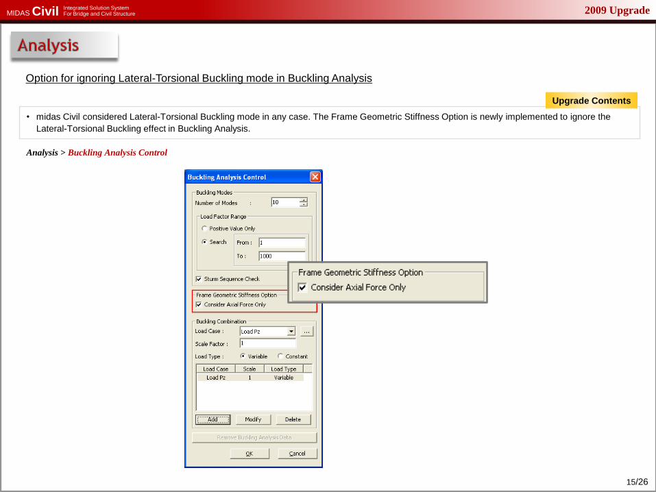
Analysis > Buckling Analysis Control
• midas Civil considered Lateral-Torsional Buckling mode in any case. The Frame Geometric Stiffness Option is newly implemented to ignore the
Lateral-Torsional Buckling effect in Buckling Analysis.
Option for ignoring Lateral-Torsional Buckling mode in Buckling Analysis
Upgrade Contents

MIDAS Civil Integrated Solution SystemFor Bridge and Civil Structure 2009 Upgrade
16/26
Analysis > Moving Load Analysis Control
Results> Result Tables> Beam> Force
• Moving Load Analysis considering Concurrent Member Forces is newly implemented.
Finding Concurrent Forces in Moving Load Analysis as per BS5400
Upgrade Contents

MIDAS Civil Integrated Solution SystemFor Bridge and Civil Structure 2009 Upgrade
17/26
Model > Boundaries> Point Spring Supports
• Nonlinear Point Spring Supports can be included in Construction Stage Analysis (Comp. -only, Tens.-only and Multi-Linear type)
Nonlinear Point Spring Supports for Construction Stage Analysis
Upgrade Contents

2009 UpgradeMIDAS Civil Integrated Solution SystemFor Bridge and Civil Structure
18/26
Model > Properties > Section
Load > Construction State Analysis Data > Composite Section for Construction Stage
Tools > Sectional Property Calculator
• Various types of composite sections can be applied to construction stage analysis.
Effects & Usage
• Composite sections can be generated, and parts of these sections can be defined in midas SPC for construction stage analysis.
• Composite sections generated from SPC can be exported to midas Civil.
Upgrade Contents
Importing Composite Sections Generated from SPC
[Composite Section in SPC] [Before composite action (Part 1+2)]
[Before composite action (Part 1)]

2009 UpgradeMIDAS Civil Integrated Solution SystemFor Bridge and Civil Structure
19/26
Model > Boundaries > Define Constraint Label Direction
View > Display > Boundary
• A new feature that displays the Support and Point Spring Support offering an intuitive way of identifying boundary conditions.
Upgrade Contents
Improvements on the Display of Supports and Point Spring Supports
[Support][Point spring support]
[Example of Label
Direction – Box Culvert]
[Define Constraint Label
Direction]

2009 UpgradeMIDAS Civil Integrated Solution SystemFor Bridge and Civil Structure
20/26
[Web-based Help]
Tools > Preferences > Environment
• The user can select a Local Help or Web-based Help in the preference.
• When „Use Local Help‟ option is checked on, a Local help file (CVLw.chm) which has been installed in the local computer is invoked by pressing „F1‟
key.
• Default setting is check-off, which invokes a Web-based Help. Since Web-based Help can be frequently updated, default setting is recommended.
Upgrade Contents
Addition of the Preference in online help

2009 UpgradeMIDAS Civil Integrated Solution SystemFor Bridge and Civil Structure
21/26
[Upside-down T-shape section] [L-shape section]
Model > Properties > Section
Tables > Structure Tables > Properties> Section
• Generate the strip foundations using upside-down T-shape beam.
• Both upside-down T-shape and L-shape section can be generated.
Upgrade Contents
Addition of upside-down T-shape beam

2009 UpgradeMIDAS Civil Integrated Solution SystemFor Bridge and Civil Structure
22/26
Model > Properties > Section
• In IS84 section DB, H-Section and Channel now reflect „r‟ value.
• T-Section has been newly added as per IS84.
Upgrade Contents
Improvements in IS84 section DB

2009 UpgradeMIDAS Civil Integrated Solution SystemFor Bridge and Civil Structure
23/26
File > Graphic files > JPG files
• Graphic data of the Model Window can be saved in JPG format as well as AutoCAD DXF, BMP or EMF.
Upgrade Contents
Save an image in JPG format

2009 UpgradeMIDAS Civil Integrated Solution SystemFor Bridge and Civil Structure
24/26
Results > Result Tables
• New feature that can export databases to an Excel Spreadsheet.
Upgrade Contents
Addition of an export option in result tables

2009 UpgradeMIDAS Civil Integrated Solution SystemFor Bridge and Civil Structure
25/26
File > Export > Frame Section for Solid, Frame Section for Plate
• Tendon Profiles as well as concrete girder can be exported to midas FEA for detail analysis.
• Exporting frame model to plate model in midas FEA is newly implemented.
Upgrade Contents
Export frame model to solid/plate model
• The user can easily generate the solid/plate model with tendons, which will be analyzed in midas FEA.
Effects & Usage
[midas Civil: line beam model]
[midas FEA: Imported tendons]
[midas FEA: Solid model]

2009 UpgradeMIDAS Civil Integrated Solution SystemFor Bridge and Civil Structure
26/26
Model > Structure Wizard > Beam
• Span-oriented input type for Beam Wizard is newly implemented.
Improvements in Beam Wizard
Upgrade Contents


![midas DShop Auto-drafting Module for midas Gen 01 02admin.midasuser.com/UploadFiles2/84/Dshop_catalog.pdf · Auto-drafting Module for midas Gen [midas Gen Design Results] [midas DShop](https://static.fdocuments.in/doc/165x107/5ade06cd7f8b9a9a768db6e7/midas-dshop-auto-drafting-module-for-midas-gen-01-module-for-midas-gen-midas-gen.jpg)