Microwave/Millimeterwave Synthesizers · The Anritsu “El Toro” synthesizers are now available...
26
Microwave/Millimeterwave Synthesizers 68C/69B Family 0.1 Hz to 110 GHz The Smart Choice for Any Application Advanced Test Equipment Rentals www.atecorp.com 800-404-ATEC (2832) ® E s t a blishe d 1 9 8 1
Transcript of Microwave/Millimeterwave Synthesizers · The Anritsu “El Toro” synthesizers are now available...
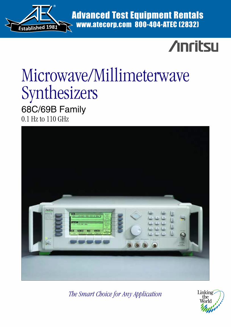
Microwave/Millimeterwave Synthesizers68C/69B Family0.1 Hz to 110 GHz
The Smart Choice for Any Application
Advanced Test Equipment Rentalswww.atecorp.com 800-404-ATEC (2832)
®
Established 1981
mjahn
Text Box
68369A/NV is equivalent to the 68347C and includes the following options as standard: Opt. 2B :10dB/step step attenuator Opt. 11: 0.1Hz frequency resolution
VALUE WITHOUT COMPROMISEYour microwave signal generation requirements have never been tougher, and yet your capital equipment budget has never beentighter. You need the most value you can get in a synthesizer, but you can’t compromise performance. You need a synthesizerthat meets today’s needs yet can be upgraded at a reasonable cost to satisfy future requirements without shattering your testequipment budget. Anritsu’s 68C/69B series of synthesizers deliver the highest performance and the highest value availabletoday. Match your application to one of these source types:
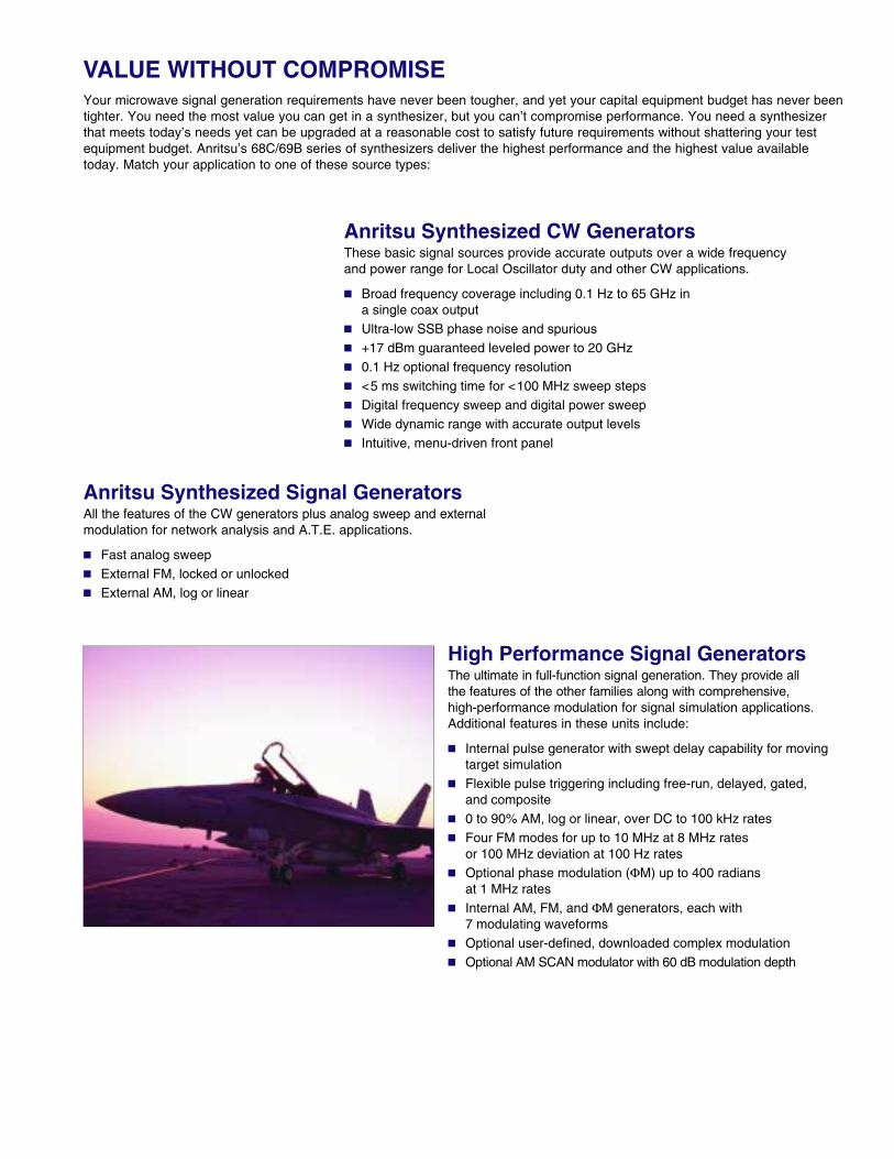
High Performance Signal GeneratorsThe ultimate in full-function signal generation. They provide allthe features of the other families along with comprehensive, high-performance modulation for signal simulation applications.Additional features in these units include:
Internal pulse generator with swept delay capability for movingtarget simulation
Flexible pulse triggering including free-run, delayed, gated,and composite
0 to 90% AM, log or linear, over DC to 100 kHz rates Four FM modes for up to 10 MHz at 8 MHz rates
or 100 MHz deviation at 100 Hz rates Optional phase modulation (ΦM) up to 400 radians
at 1 MHz rates Internal AM, FM, and ΦM generators, each with
7 modulating waveforms Optional user-defined, downloaded complex modulation Optional AM SCAN modulator with 60 dB modulation depth
Anritsu Synthesized Signal GeneratorsAll the features of the CW generators plus analog sweep and externalmodulation for network analysis and A.T.E. applications.
Fast analog sweep External FM, locked or unlocked External AM, log or linear
Anritsu Synthesized CW GeneratorsThese basic signal sources provide accurate outputs over a wide frequencyand power range for Local Oscillator duty and other CW applications.
Broad frequency coverage including 0.1 Hz to 65 GHz ina single coax output
Ultra-low SSB phase noise and spurious +17 dBm guaranteed leveled power to 20 GHz 0.1 Hz optional frequency resolution <5 ms switching time for <100 MHz sweep steps Digital frequency sweep and digital power sweep Wide dynamic range with accurate output levels Intuitive, menu-driven front panel
2
68XXXC AND 69XXXB 68XXXC AND 69XXXB
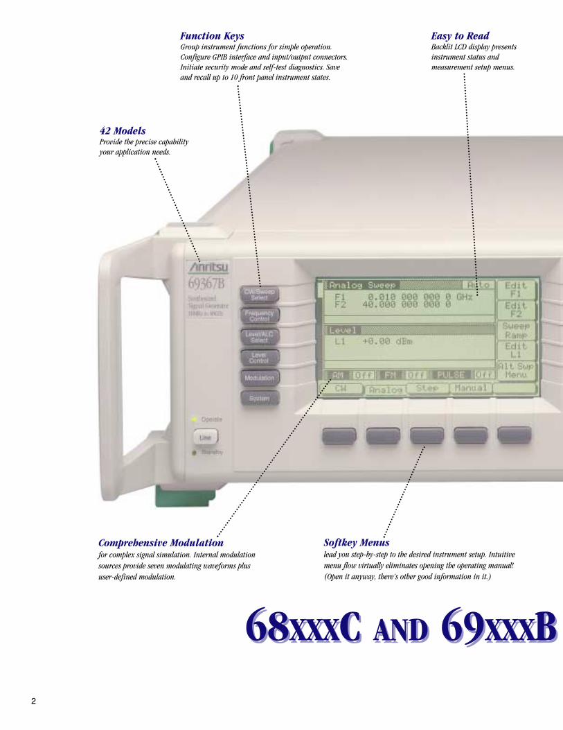
42 ModelsProvide the precise capabilityyour application needs.
Function KeysGroup instrument functions for simple operation.Configure GPIB interface and input/output connectors.Initiate security mode and self-test diagnostics. Saveand recall up to 10 front panel instrument states.
Easy to ReadBacklit LCD display presentsinstrument status andmeasurement setup menus.
Softkey Menuslead you step-by-step to the desired instrument setup. Intuitivemenu flow virtually eliminates opening the operating manual!(Open it anyway, there’s other good information in it.)
Comprehensive Modulationfor complex signal simulation. Internal modulationsources provide seven modulating waveforms plususer-defined modulation.
FAMILY SYNTHESIZERSFAMILY SYNTHESIZERS
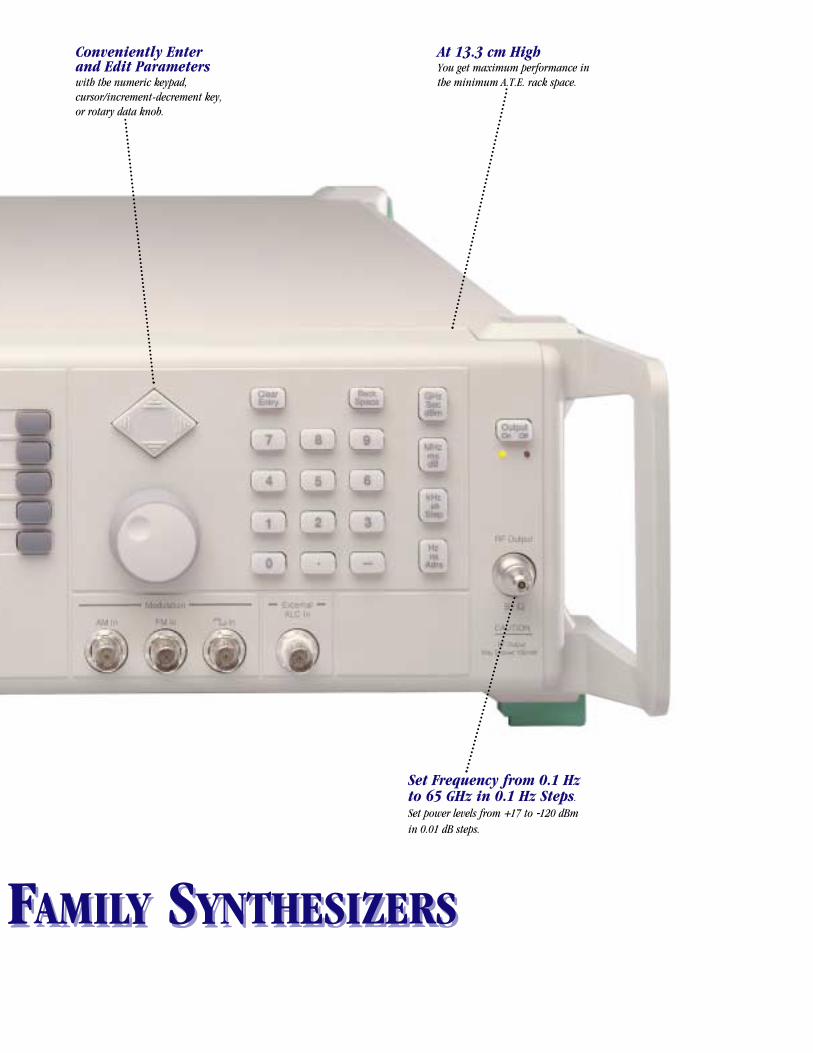
Conveniently Enterand Edit Parameterswith the numeric keypad,cursor/increment-decrement key,or rotary data knob.
At 13.3 cm HighYou get maximum performance inthe minimum A.T.E. rack space.
Set Frequency from 0.1 Hzto 65 GHz in 0.1 Hz Steps.Set power levels from +17 to -120 dBmin 0.01 dB steps.
3
TO THE ULTIMATE
INTERCHANGEABLE VIRTUAL INSTRUMENTS STANDARD
In local oscillator and other basic-signal applications, you needhigh output power, low phase noise, excellent frequency stabilityand low spurious signal levels. The 69017B provides +17 dBmoutput power while ultra-low SSB phase noise and spurioussignals below –60 dBc preserve signal fidelity. Oven-stabilizedinternal reference oscillators with <5x10⁻¹⁰ per day frequencystability keep you on channel. When you need to addbroader frequency coverage, modulation, or frequency andpower sweep, simply upgrade to the performance you need.
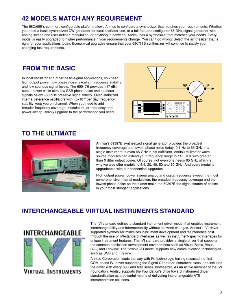
Anritsu’s 69397B synthesized signal generator provides the broadestfrequency coverage and lowest phase noise today, 0.1 Hz to 65 GHz in asingle instrument! If even 65 GHz is not sufficient, Anritsu millimeter wavesource modules can extend your frequency range to 110 GHz with greaterthan 0 dBm output power. Of course, not everyone needs 65 GHz which iswhy we also offer models to 8.4, 20, 40, 50 and 60 GHz. And every model isupgradeable with our economical upgrades.
High output power, power sweep analog and digital frequency sweep, the mostcomprehensive internal modulation, the broadest frequency coverage and thelowest phase noise on the planet make the 69397B the signal source of choicein your most stringent applications.
The 68C/69B’s common, configurable platform allows Anritsu to configure a synthesizer that matches your requirements. Whetheryou need a basic synthesized CW generator for local oscillator use, or a full-featured configured 65 GHz signal generator withanalog sweep and user-defined modulation, or anything in between. Anritsu has a synthesizer that matches your needs. Everymodel is easily upgraded to higher performance if your requirements change. You can’t go wrong! Select the synthesizer that isright for your applications today. Economical upgrades ensure that your 68C/69B synthesizer will continue to satisfy yourchanging test requirements.
42 MODELS MATCH ANY REQUIREMENT
FROM THE BASIC
LO
RF IF
The IVI standard defines a standard instrument driver model that enables instrumentinterchangeability and interoperability without software changes. Anritsu’s IVI-driversupported synthesizer minimizes instrument development and maintanence costthrough the use of IVI-standard interfaces as well as instrument-specific interfaces forunique instrument features. The IVI standard provides a single driver that supportsthe common application development environments such as Visual Basic, VisualC++, and Labview. The flexible I/O model supports new communication technologiessuch as USB and Firewire.
Anritsu Corporation leads the way with IVI technology, having released the firstCOM-based IVI driver supporting the Signal Generator instrument class, and includesthe driver with every 68C and 69B series synthesizer. As an active member of the IVIFoundation, Anritsu supports the Foundation’s drive toward instrument driverstandardization as a powerful means of delivering interchangeable ATEinstrumentation solutions.
4
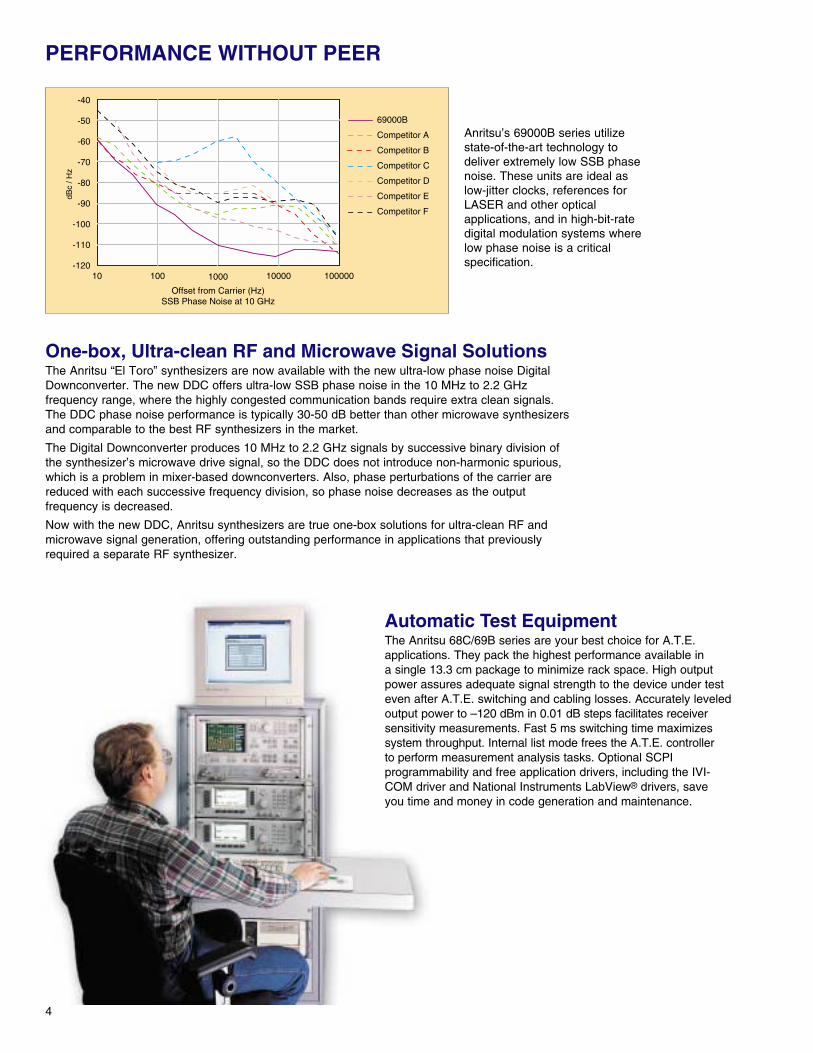
PERFORMANCE WITHOUT PEER
Anritsu’s 69000B series utilizestate-of-the-art technology todeliver extremely low SSB phasenoise. These units are ideal aslow-jitter clocks, references forLASER and other opticalapplications, and in high-bit-ratedigital modulation systems wherelow phase noise is a criticalspecification.
-40
-50
-60
-70
-80
-90
-100
-110
-12010 100 1000 10000 100000
69000B
Competitor A
Competitor B
Competitor C
Competitor D
Competitor E
Competitor F
Offset from Carrier (Hz)SSB Phase Noise at 10 GHz
dBc
/ Hz
Automatic Test EquipmentThe Anritsu 68C/69B series are your best choice for A.T.E.applications. They pack the highest performance available ina single 13.3 cm package to minimize rack space. High outputpower assures adequate signal strength to the device under testeven after A.T.E. switching and cabling losses. Accurately leveledoutput power to –120 dBm in 0.01 dB steps facilitates receiversensitivity measurements. Fast 5 ms switching time maximizessystem throughput. Internal list mode frees the A.T.E. controllerto perform measurement analysis tasks. Optional SCPIprogrammability and free application drivers, including the IVI-COM driver and National Instruments LabView® drivers, saveyou time and money in code generation and maintenance.
One-box, Ultra-clean RF and Microwave Signal SolutionsThe Anritsu “El Toro” synthesizers are now available with the new ultra-low phase noise DigitalDownconverter. The new DDC offers ultra-low SSB phase noise in the 10 MHz to 2.2 GHzfrequency range, where the highly congested communication bands require extra clean signals.The DDC phase noise performance is typically 30-50 dB better than other microwave synthesizersand comparable to the best RF synthesizers in the market.
The Digital Downconverter produces 10 MHz to 2.2 GHz signals by successive binary division ofthe synthesizer’s microwave drive signal, so the DDC does not introduce non-harmonic spurious,which is a problem in mixer-based downconverters. Also, phase perturbations of the carrier arereduced with each successive frequency division, so phase noise decreases as the outputfrequency is decreased.
Now with the new DDC, Anritsu synthesizers are true one-box solutions for ultra-clean RF andmicrowave signal generation, offering outstanding performance in applications that previouslyrequired a separate RF synthesizer.
IN EVERY APPLICATION
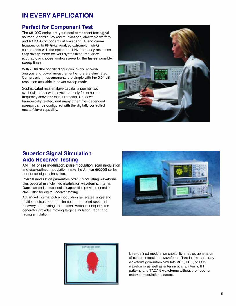
Perfect for Component TestThe 68100C series are your ideal component test signalsources. Analyze key communications, electronic warfareand RADAR components at baseband, IF and carrierfrequencies to 65 GHz. Analyze extremely high-Qcomponents with the optional 0.1 Hz frequency resolution.Step sweep mode delivers synthesized frequencyaccuracy, or choose analog sweep for the fastest possiblesweep times.
With <–60 dBc specified spurious levels, networkanalysis and power measurement errors are eliminated.Compression measurements are simple with the 0.01 dBresolution available in power sweep mode.
Sophisticated master/slave capability permits twosynthesizers to sweep synchronously for mixer orfrequency converter measurements. Up, down,harmonically related, and many other inter-dependentsweeps can be configured with the digitally-controlledmaster/slave capability.
5
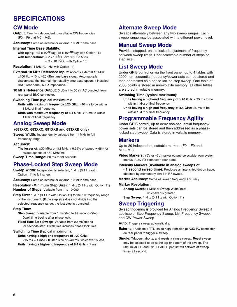
Superior Signal Simulation Aids Receiver TestingAM, FM, phase modulation, pulse modulation, scan modulationand user-defined modulation make the Anritsu 69300B seriesperfect for signal simulation.
Internal modulation generators offer 7 modulating waveformsplus optional user-defined modulation waveforms. InternalGaussian and uniform noise capabilities provide controlledclock jitter for digital receiver testing.
Advanced internal pulse modulation generates single andmultiple pulses, for the ultimate in radar blind spot andrecovery time testing. In addition, Anritsu’s unique pulsegenerator provides moving target simulation, radar andfading simulation.
User-defined modulation capability enables generationof custom modulated waveforms. Two internal arbitrarywaveform generators simulate ASK, PSK, or FSKwaveforms as well as antenna scan patterns, IFFpatterns and TACAN waveforms without the need forexternal modulation sources.
6
CW ModeOutput: Twenty independent, presettable CW frequencies
(F0 – F9 and M0 – M9).
Accuracy: Same as internal or external 10 MHz time base.
Internal Time Base Stability:with aging: < 2 x 10⁻⁸/day (<5 x 10⁻¹⁰/day with Option 16)with temperature: < 2 x 10⁻⁸/°C over 0°C to 55°C
(<2 x 10⁻¹⁰/°C with Option 16)
Resolution: 1 kHz (0.1 Hz with Option 11)
External 10 MHz Reference Input: Accepts external 10 MHz±100 Hz, –10 to +20 dBm time base signal. Automaticallydisconnects the internal high-stability time-base option, if installedBNC, rear panel, 50 Ω impedance.
10 MHz Reference Output: 0 dBm into 50 Ω, AC coupled, fromrear panel BNC connector.
Switching Time (typical maximum):Units with maximum frequency ≥ 20 GHz: <40 ms to be within
1 kHz of final frequencyUnits with maximum frequency of 8.4 GHz: <15 ms to within
1 kHz of final frequency
Analog Sweep Mode(681XXC, 683XXC, 691XXB and 693XXB only)Sweep Width: Independently selected from 1 MHz to full
frequency range.
Accuracy:The lesser of: ±30 MHz or (±2 MHz + 0.25% of sweep width) for
sweep speeds of ≤50 MHz/msSweep Time Range: 30 ms to 99 seconds
Phase-Locked Step Sweep ModeSweep Width: Independently selected, 1 kHz (0.1 Hz with
Option 11) to full range.
Accuracy: Same as internal or external 10 MHz time base.
Resolution (Minimum Step Size): 1 kHz (0.1 Hz with Option 11)Number of Steps: Variable from 1 to 10,000
Step Size: 1 kHz (0.1 Hz with Option 11) to the full frequency rangeof the instrument. (If the step size does not divide into theselected frequency range, the last step is truncated.)
Step Time:Step Sweep: Variable from 1 ms/step to 99 seconds/step.
Dwell time begins after phase lock.Fixed Rate Step Sweep: Variable from 20 ms/step to
99 seconds/step. Dwell time includes phase lock time.
Switching Time (typical maximum):Units having a high-end frequency of ≥20 GHz:
<15 ms + 1 ms/GHz step size or <40 ms, whichever is less.Units having a high-end frequency of 8.4 GHz: <7 ms
Alternate Sweep ModeSweeps alternately between any two sweep ranges. Eachsweep range may be associated with a different power level.
Manual Sweep ModeProvides stepped, phase-locked adjustment of frequencybetween sweep limits. User-selectable number of steps orstep size.
List Sweep ModeUnder GPIB control or via the front panel, up to 4 tables with2000 non-sequential frequency/power sets can be stored andthen addressed as a phase-locked step sweep. One table of2000 points is stored in non-volatile memory, all other tablesare stored in volatile memory.
Switching Time (typical maximum): Units having a high-end frequency of ≥ 20 GHz: <25 ms to be
within 1 kHz of final frequency.Units having a high-end frequency of 8.4 GHz: <5 ms to be
within 1 kHz of final frequency.
Programmable Frequency AgilityUnder GPIB control, up to 3202 non-sequential frequency/power sets can be stored and then addressed as a phase-locked step sweep. Data is stored in volatile memory.
MarkersUp to 20 independent, settable markers (F0 – F9 and M0 – M9).
Video Markers: +5V or –5V marker output, selectable from systemmenus. AUX I/O connector, rear panel.
Intensity Markers (Available in analog sweeps of<1 second sweep time): Produces an intensified dot on trace,obtained by momentary dwell in RF sweep.
Marker Accuracy: Same as sweep frequency accuracy.
Marker Resolution :Analog Sweep: 1 MHz or Sweep Width/4096,
whichever is greater.Step Sweep: 1 kHz (0.1 Hz with Option 11)
Sweep TriggeringSweep triggering is provided for Analog Frequency Sweep ifapplicable, Step Frequency Sweep, List Frequency Sweep,and CW Power Sweep.
Auto: Triggers sweep automatically.
External: Accepts a TTL low to high transition at AUX I/O connectoron rear panel to trigger a sweep.
Single: Triggers, aborts, and resets a single sweep. Reset sweepmay be selected to be at the top or bottom of the sweep. The68100C/300C and 69100B/300B pen lift will activate at sweeptimes ≥1 second.
SPECIFICATIONS
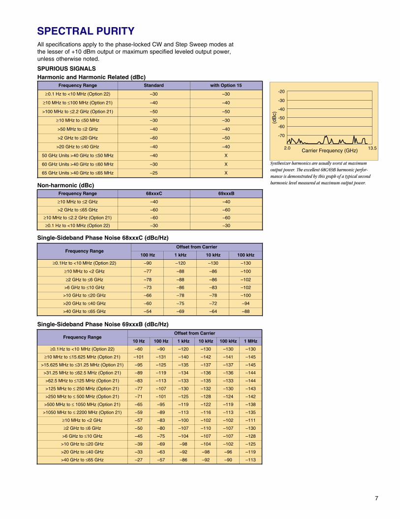
Synthesizer harmonics are usually worst at maximumoutput power. The excellent 68C/69B harmonic perfor-mance is demonstrated by this graph of a typical secondharmonic level measured at maximum output power.
7
SPECTRAL PURITYAll specifications apply to the phase-locked CW and Step Sweep modes at the lesser of +10 dBm output or maximum specified leveled output power, unless otherwise noted.
SPURIOUS SIGNALSHarmonic and Harmonic Related (dBc)
Non-harmonic (dBc)
Single-Sideband Phase Noise 68xxxC (dBc/Hz)
Single-Sideband Phase Noise 69xxxB (dBc/Hz)
(dB
c)
Carrier Frequency (GHz)2.0 13.5
-20
-30
-40
-50
-60
-70
Frequency Range Standard with Option 15
≥0.1 Hz to <10 MHz (Option 22) –30 –30
≥10 MHz to ≤50 MHz –30 –30
>50 MHz to ≤2 GHz –40 –40
>2 GHz to ≤20 GHz –60 –50
>20 GHz to ≤40 GHz –40 –40
50 GHz Units >40 GHz to ≤50 MHz –40 X
60 GHz Units >40 GHz to ≤60 MHz –30 X
65 GHz Units >40 GHz to ≤65 MHz –25 X
Frequency Range 68xxxC 69xxxB
≥10 MHz to ≤2 GHz –40 –40
>2 GHz to ≤65 GHz –60 –60
≥10 MHz to ≤2.2 GHz (Option 21) –60 –60
Frequency RangeOffset from Carrier
100 Hz 10 kHz
≥0.1Hz to <10 MHz (Option 22) –90 –130
≥10 MHz to <2 GHz –77 –86
≥2 GHz to ≤6 GHz –78 –86
>6 GHz to ≤10 GHz –73 –83
>10 GHz to ≤20 GHz –66 –78
>20 GHz to ≤40 GHz –60 –72
>40 GHz to ≤65 GHz –54 –64
1 kHz
–120
–88
–88
–86
–78
–75
–69
100 kHz
–130
–100
–102
–102
–100
–94
–88
>100 MHz to ≤2.2 GHz (Option 21) –50 –50
≥10 MHz to ≤100 MHz (Option 21) –40 –40
≥0.1 Hz to <10 MHz (Option 22) –30 –30
Frequency RangeOffset from Carrier
10 Hz 1 kHz 10 kHz 100 kHz 1 MHz
≥0.1Hz to <10 MHz (Option 22) –60 –120 –130 –130 –130
≥10 MHz to ≤15.625 MHz (Option 21) –101 –140 –142 –141 –145
>15.625 MHz to ≤31.25 MHz (Option 21) –95 –135 –137 –137 –145
>31.25 MHz to ≤62.5 MHz (Option 21) –89 –134 –136 –136 –144
>62.5 MHz to ≤125 MHz (Option 21) –83 –133 –135 –133 –144
>125 MHz to ≤ 250 MHz (Option 21) –77 –130 –132 –130 –143
>250 MHz to ≤ 500 MHz (Option 21) –71 –125 –128 –124 –142
>500 MHz to ≤ 1050 MHz (Option 21) –65 –119 –122 –119 –138
>1050 MHz to ≤ 2200 MHz (Option 21) –59 –113 –116 –113 –135
≥10 MHz to <2 GHz –57 –100 –102 –102 –111
≥2 GHz to ≤6 GHz –50 –107 –110 –107 –130
>6 GHz to ≤10 GHz –45 –104 –107 –107 –128
>10 GHz to ≤20 GHz –39 –98 –104 –102 –125
>20 GHz to ≤40 GHz –33 –92 –98 –96 –119
>40 GHz to ≤65 GHz –27 –86 –92 –90 –113
100 Hz
–90
–131
–125
–119
–113
–107
–101
–95
–89
–83
–80
–75
–69
–63
–57
8
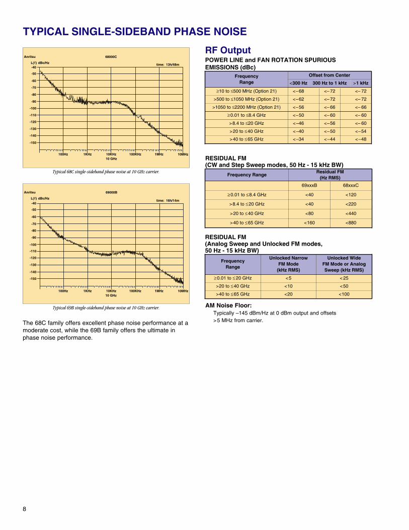
Typical 68C single-sideband phase noise at 10 GHz carrier.
Typical 69B single-sideband phase noise at 10 GHz carrier.
RF OutputPOWER LINE and FAN ROTATION SPURIOUSEMISSIONS (dBc)
RESIDUAL FM(CW and Step Sweep modes, 50 Hz - 15 kHz BW)
RESIDUAL FM(Analog Sweep and Unlocked FM modes, 50 Hz - 15 kHz BW)
AM Noise Floor:Typically –145 dBm/Hz at 0 dBm output and offsets >5 MHz from carrier.
TYPICAL SINGLE-SIDEBAND PHASE NOISE
The 68C family offers excellent phase noise performance at amoderate cost, while the 69B family offers the ultimate inphase noise performance.
Anritsu 68000C
time: 13h/48mL(f) dBc/Hz
10 GHz100Hz 1KHz 10KHz 100KHz 1MHz 10MHz
-40
-50
-60
-70
-80
-90
-100
-110
-120
-130
-140
-150
Anritsu 69000B
time: 16h/14mL(f) dBc/Hz
10 GHz100Hz 1KHz 10KHz 100KHz 1MHz 10MHz
-40
-50
-60
-70
-80
-90
-100
-110
-120
-130
-140
-150
Frequency Range
Offset from Center
<300 Hz 300 Hz to 1 kHz >1 kHz
≥0.01 to ≤8.4 GHz <–50 <– 60 <– 60
>8.4 to ≤20 GHz <–46 <–56 <– 60
>20 to ≤40 GHz <–40 <–50 <–54
>40 to ≤65 GHz <–34 <–44 <–48
Frequency RangeResidual FM
(Hz RMS)
69xxxB
≥0.01 to ≤8.4 GHz <40
>8.4 to ≤20 GHz <40
>20 to ≤40 GHz <80
>40 to ≤65 GHz <160
68xxxC
<120
<220
<440
<880
FrequencyRange
Unlocked NarrowFM Mode
(kHz RMS)
Unlocked WideFM Mode or AnalogSweep (kHz RMS)
≥0.01 to ≤ 20 GHz <5 < 25
>20 to ≤40 GHz <10 <50
>40 to ≤65 GHz <20 <100
≥10 to ≤500 MHz (Option 21) <–68 <– 72 <– 72
>1050 to ≤2200 MHz (Option 21) <–56 <– 66 <– 66
>500 to ≤1050 MHz (Option 21) <–62 <– 72 <– 72
9
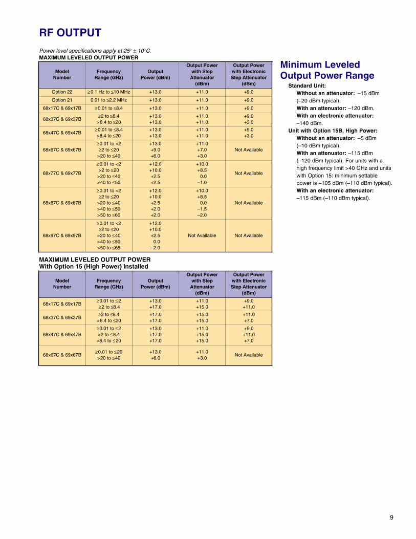
MAXIMUM LEVELED OUTPUT POWERWith Option 15 (High Power) Installed
Power level specifications apply at 25° ± 10°C.MAXIMUM LEVELED OUTPUT POWER
RF OUTPUT
Minimum LeveledOutput Power Range
Standard Unit:Without an attenuator: –15 dBm(–20 dBm typical).With an attenuator: –120 dBm.With an electronic attenuator:–140 dBm.
Unit with Option 15B, High Power:Without an attenuator: –5 dBm(–10 dBm typical).With an attenuator: –115 dBm(–120 dBm typical). For units with ahigh frequency limit >40 GHz and unitswith Option 15: minimum settablepower is –105 dBm (–110 dBm typical).With an electronic attenuator:–115 dBm (–110 dBm typical).
ModelNumber
FrequencyRange (GHz)
OutputPower (dBm)
Output Powerwith Step
Attenuator(dBm)
Output Powerwith ElectronicStep Attenuator
(dBm)
Option 22 ≥0.1 Hz to ≤10 MHz +13.0 +11.0 +9.0
68x17C & 69x17B ≥0.01 to ≤8.4 +13.0 +11.0 +9.0
68x37C & 69x37B≥2 to ≤8.4
>8.4 to ≤20+13.0+13.0
+11.0+11.0
+9.0+3.0
68x47C & 69x47B≥0.01 to ≤8.4>8.4 to ≤20
+13.0+13.0
+11.0+11.0
+9.0+3.0
68x67C & 69x67B≥0.01 to <2≥2 to ≤20
>20 to ≤40
+13.0+9.0+6.0
+11.0+7.0+3.0
Not Available
68x77C & 69x77B
≥0.01 to <2>2 to ≤20>20 to ≤40>40 to ≤50
+12.0+10.0+2.5+2.5
+10.0+8.5
0.0–1.0
Not Available
68x87C & 69x87B
≥0.01 to <2≥2 to ≤20
>20 to ≤40>40 to ≤50>50 to ≤60
+12.0+10.0+2.5+2.0+2.0
+10.0+8.5
0.0–1.5–2.0
Not Available
68x97C & 69x97B
≥0.01 to <2≥2 to ≤20
>20 to ≤40>40 to ≤50>50 to ≤65
+12.0+10.0+2.5
0.0–2.0
Not Available Not Available
ModelNumber
FrequencyRange (GHz)
OutputPower (dBm)
Output Powerwith Step
Attenuator(dBm)
Output Powerwith ElectronicStep Attenuator
(dBm)
68x17C & 69x17B≥0.01 to ≤2≥2 to ≤8.4
+13.0+17.0
+11.0+15.0
+9.0+11.0
68x37C & 69x37B≥2 to ≤8.4
>8.4 to ≤20+17.0+17.0
+15.0+15.0
+11.0+7.0
68x47C & 69x47B≥0.01 to ≤2>2 to ≤8.4
>8.4 to ≤20
+13.0+17.0+17.0
+11.0+15.0+15.0
+9.0+11.0+7.0
68x67C & 69x67B≥0.01 to ≤20>20 to ≤40
+13.0+6.0
+11.0+3.0
Not Available
Option 21 0.01 to ≤2.2 MHz +13.0 +11.0 +9.0
10
RF OUTPUT
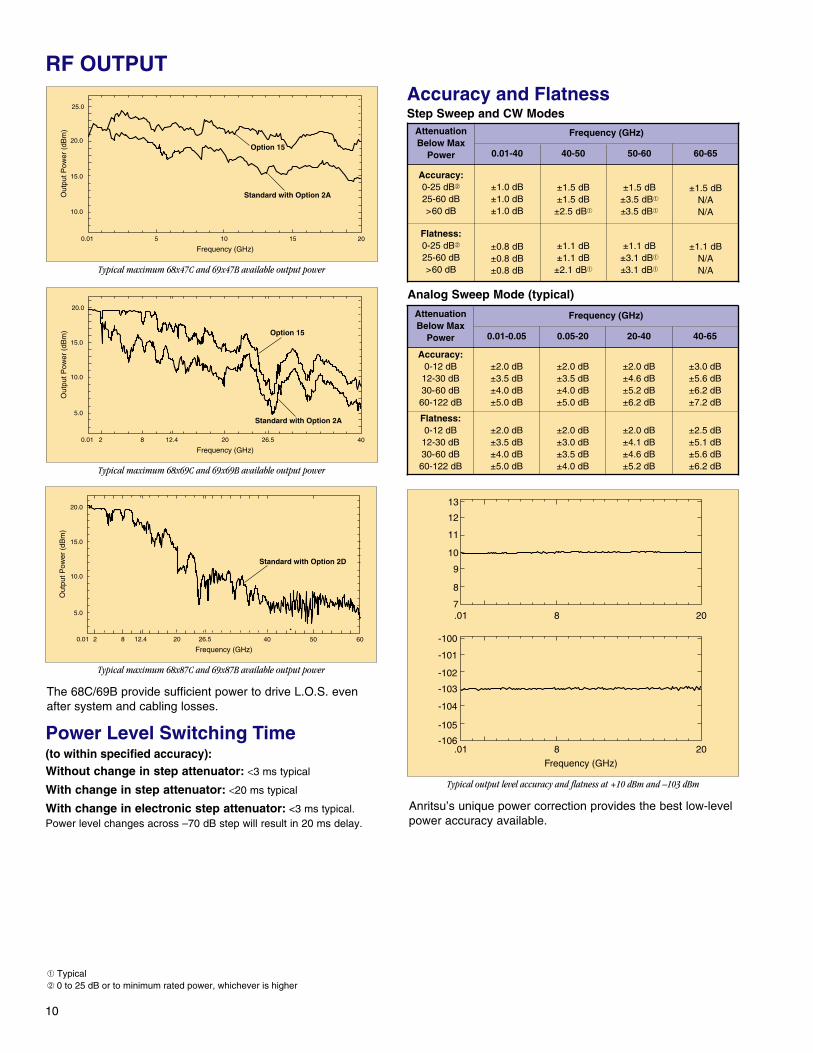
Typical maximum 68x47C and 69x47B available output power
Typical maximum 68x69C and 69x69B available output power
Typical maximum 68x87C and 69x87B available output power
The 68C/69B provide sufficient power to drive L.O.S. evenafter system and cabling losses.
Accuracy and FlatnessStep Sweep and CW Modes
➀ Typical➁ 0 to 25 dB or to minimum rated power, whichever is higher
Typical output level accuracy and flatness at +10 dBm and –103 dBm
Anritsu’s unique power correction provides the best low-levelpower accuracy available.
Power Level Switching Time(to within specified accuracy):Without change in step attenuator: <3 ms typical
With change in step attenuator: <20 ms typical
With change in electronic step attenuator: <3 ms typical.Power level changes across –70 dB step will result in 20 ms delay.
Analog Sweep Mode (typical)
.01 8 20
.01 8 20
-100
-101
-102
-103
-104
-105
-106
13
12
11
10
9
8
7
Frequency (GHz)
25.0
20.0
Out
put P
ower
(dB
m)
0.01 5 20
Frequency (GHz)
15.0
10.0
Standard with Option 2A
10 15
Option 15
20.0
15.0
Out
put P
ower
(dB
m)
0.01 2 8 12.4 40
Frequency (GHz)26.520
Option 15
Standard with Option 2A
10.0
5.0
20.0
15.0
10.0
Out
put P
ower
(dB
m)
0.01 2 8 12.4 40
Frequency (GHz)26.520
5.0
50 60
Standard with Option 2D
Frequency (GHz)
Accuracy:0-25 dB➁
25-60 dB>60 dB
±1.0 dB±1.0 dB±1.0 dB
±1.5 dB±1.5 dB
±2.5 dB➀
±1.5 dB±3.5 dB➀
±3.5 dB➀
±1.5 dBN/AN/A
Flatness:0-25 dB➁
25-60 dB>60 dB
±0.8 dB±0.8 dB±0.8 dB
±1.1 dB±1.1 dB
±2.1 dB➀
±1.1 dB±3.1 dB➀
±3.1 dB➀
±1.1 dBN/AN/A
0.01-40 40-50 50-60 60-65
Frequency (GHz)
Accuracy:0-12 dB
12-30 dB30-60 dB60-122 dB
±2.0 dB±3.5 dB±4.0 dB±5.0 dB
±2.0 dB±3.5 dB±4.0 dB±5.0 dB
±2.0 dB±4.6 dB±5.2 dB±6.2 dB
±3.0 dB±5.6 dB±6.2 dB±7.2 dB
Flatness:0-12 dB
12-30 dB30-60 dB60-122 dB
±2.0 dB±3.5 dB±4.0 dB±5.0 dB
±2.0 dB±3.0 dB±3.5 dB±4.0 dB
±2.0 dB±4.1 dB±4.6 dB±5.2 dB
±2.5 dB±5.1 dB±5.6 dB±6.2 dB
0.01-0.05 0.05-20 20-40 40-65
AttenuationBelow Max
Power
AttenuationBelow Max
Power
11
➂ When Option 8 Power Meter is installed, Option 7 (Delete AM/FMGenerators) is not available.
Other Output Power SpecificationsOutput Units: Output units selectable as either dBm or mV.Selection of mV assumes 50Ω load. All data entries and displays arein the selected units.
Output Power Resolution: 0.01 dB or 0.001 mV
Source Impedance: 50Ω nominal
Source SWR (Internal Leveling): <2.0 typicalPower Level Stability with Temperature: 0.04 dB/°C typicalLevel Offset: Offsets the displayed power level to establish a new
reference level.
Internal Leveling: Power is leveled at the output connector inall modes.
External Leveling:External Detector: Levels output power at a remote detectorlocation. Accepts a positive or negative 0.5 mV to 500 mV inputfrom the remote detector. EXT ALC ADJUST adjusts the inputsignal range to an optimum value. BNC connector, front andrear panel.External Power Meter: Levels output power at a remote powermeter location. Accepts a ±1V full scale signal from the remotepower meter. EXT ALC ADJUST adjusts the input signal range toan optimum value. BNC connector, front and rear panel.External Leveling Bandwidth:
30 kHz typical in Detector mode.0.7 Hz typical in Power Meter mode.
User Level Flatness Correction:Number of points: 2 to 801 points per tableNumber of tables: 5 availableEntry modes: GPIB power meter or computed data
CW Power SweepRange: Sweeps between any two power levels at a single
CW frequency.
Resolution: 0.01 dB/step (Log) or 0.001 mV/step (Linear)
Accuracy: Same as CW power accuracy.
Step Size: User-controlled, 0.01 dB (Log) or 0.001 mV (Linear) tothe full power range of the instrument.
Step Dwell Time: Variable from 1 ms to 99 seconds. If the sweepcrosses a step attenuator setting, there will be a sweep dwell ofapproximately 20 ms to allow setting of the step attenuator.
Sweep Frequency/Step PowerA power level step occurs after each frequency sweep. Thepower level remains constant for the length of time requiredto complete each sweep.
Internal Power Measurement(Option 8 on 68300C and 69300B only)➂
Sensors: Compatible with Anritsu 560-7, 5400-71, or6400-71 Series Detectors. Rear panel input.
Range: +16 dBm to −35 dBm.
Accuracy: ±1 dB (+10 dBm to –10 dBm)± 2 dB (-10 dBm to –35 dBm)
Resolution: 0.1 dB minimum
12
Amplitude ModulationAll amplitude modulation specifications apply at 50% depth,1 kHz rate, with RF level set 6 dB below maximum specifiedleveled output power, unless otherwise noted.
AM Depth (typical): 0-90% linear; 20 dB log
AM Bandwidth (3 dB): DC to 50 kHz minimumDC to 100 kHz typical
Flatness (DC to 10 kHz rates): ±0.3 dB
Accuracy: ±5%
Distortion: <5% typical
Incidental Phase Modulation (30% depth, 10 kHz rate): <0.2 radians
External AM Input: Log AM or Linear AM input, front or rear-panelBNC, 50 Ω or 600 Ω input impedance. All options selectable frommodulation menu.
AM Sensitivity:Log AM: Continuously variable from 0 dB per volt to
25 dB per volt.Linear AM: Continuously variable from 0% per volt to
100% per volt.Maximum Input: ±1V
Frequency ModulationMaximum FM Deviation:
Locked Mode (1 kHz to 500 kHz rates): The lesser of ±10 MHzor rate x 300
Unlocked Narrow Mode (DC to 500 kHz rates) : ± 10 MHzUnlocked Wide Mode DC to 100 Hz rates: ± 100 MHz
FM Bandwidth (3 dB):Locked Mode : 1 kHz to 500 kHzUnlocked Narrow Mode: DC to 500 kHzUnlocked Wide Mode : DC to 100 Hz
Flatness locked mode (10 kHz to 500 kHz rates: ±1 dB
Accuracy (100 kHz rate, ±1 V input): 10% (5% typical)
External FM Input: Front or rear panel BNC, 50 Ω or 600 Ω inputimpedance. All options selectable from modulation menu.
FM Sensitivity: Continuously variable from ±10 kHz per volt to ±20 MHz per volt (Locked and Unlocked Narrow FM modes),or ±100 kHz per volt to ±100 MHz per volt (Unlocked Wide FMmode), selectable from modulation menu.
Maximum Input: ±1V
Square Wave ModulationThe RF output can be pulse modulated via an externalmodulating signal or an internal square wave generator.
On/Off Ratio: >50 dB
Rise/Fall Time: < 1 µs typical
Internal Square Wave Generator: Four square wave signals(400 Hz, 1 kHz, 7.8125 kHz, and 27.8 kHz), selectable frommodulation menu.Accuracy: Same as internal or external 10 MHz time base.Square Wave Symmetry: 50% ±5%
External Input: Front or rear-panel BNC, selectable frommodulation menu.Drive Level: TTL compatible inputMinimum Pulse Width: >5 µsInput Logic: Positive-true or negative-true, selectable from
modulation menu.
681XXC/691XXB MODULATION
13
Amplitude ModulationAll amplitude modulation specifications apply at 50% depth,1 kHz rate, with RF level set 6 dB below maximum specifiedleveled output power, unless otherwise noted.
AM Depth (typical): 0-90% linear; 20 dB log
AM Bandwidth (3 dB): DC to 50 kHz minimumDC to 100 kHz typical
Flatness (DC to 10 kHz rates): ± 0.3 dB
Accuracy: ± 5%
Distortion: < 5% typical
Incidental Phase Modulation (30% depth, 10 kHz rate): < 0.2 radians typicalExternal AM Input: Log AM or Linear AM input, front or rear-panel
BNC, 50 Ω or 600 Ω input impedance. All options selectable frommodulation menu.Sensitivity:
Log AM: Continuously variable from 0 dB per volt to 25 dB per volt.
Linear AM: Continuously variable from 0% per volt to 100% per volt.
Maximum Input: ±1V
Internal AM Generator:Waveforms: Sinusoid, squarewave, triangle, positive ramp,
negative ramp, Gaussian noise, uniform noise, user-defined➃
Rate: 0.1 Hz to 1 MHz sinusoidal0.1 Hz to 100 kHz squarewave, triangle, ramps
Resolution: 0.1 HzAccuracy: Same as instrument timebaseOutput: BNC connector, rear panel
Frequency ModulationMaximum FM Deviation:Locked Mode (1 kHz to 8 MHz rates): The lesser of ±10 MHz or
rate x 300Locked Low Noise Mode (50 kHz to 8 MHz rates): The lesser of
±10 MHz or rate x 3Unlocked Narrow Mode (DC to 8 MHz rates): ±10 MHzUnlocked Wide Mode (DC to 100 Hz rates): ±100 MHz
FM Bandwidth (3 dB):Locked Mode: 1 kHz to 10 MHzLocked Low Noise Mode: 30 kHz to 10 MHzUnlocked Narrow Mode: DC to 10 MHzUnlocked Wide Mode: DC to 100 Hz
Flatness (locked mode 10 kHz to 1 MHz rates):➄ ±1 dB
Accuracy (100 kHz rate):➄ 10% (5% typical)
Incidental AM (± 1 MHz deviation, 1 MHz rate): <2%
Harmonic Distortion (±1 MHz deviation, 10 kHz rate): <1%
External FM Input: Front or rear panel BNC, 50 Ω or 600 Ω inputimpedance. All options selectable from modulation menu.FM Sensitivity: Continuously variable from ±10 kHz per volt to
±20 MHz per volt (Locked, Locked Low Noise and UnlockedNarrow FM modes), or ±100 kHz per volt to ±100 MHz per volt(Unlocked Wide FM mode), selectable from modulation menu.
Maximum Input: ±1V
Internal FM Generator:Waveforms: Sinusoid, squarewave, triangle, positive ramp,
negative ramp, Gaussain noise, uniform noise, user-defined➃
Rate: 0.1 Hz to 1 MHz sinusoidal0.1 Hz to 100 kHz squarewave, triangle, ramps
Resolution: 0.1 HzAccuracy: Same as instrument timebaseOutput: BNC connector, rear panel
Phase Modulation (FM, Option 6)ΦM Deviation:
Narrow Mode (DC to 8 MHz Rates): The lesser of ±3 radiansor ±5 MHz/rate
Wide Mode (DC to 1 MHz Rates): The lesser of ±400 radiansor ±10 MHz/rate.
ΦM Bandwidth (3 dB, relative to 100 kHz rate):Narrow Mode: DC to 10 MHzWide Mode: DC to 1 MHz
ΦM Flatness (relative to 100 kHz rate):Narrow Mode (DC to 1 MHz rates): ±1 dBWide Mode (DC to 500 kHz rates): ±1 dB
ΦM Accuracy (at 100 kHz sine wave): 10%➄
External ΦM Input: Front or rear panel BNC (shares theFM input), 50 Ω or 600 Ω input impedance. All options selectablefrom modulation menu. Shares connectors with FM.ΦM Sensitivity: Continuously variable from ±0.0025 radians per
volt to ±5.0 radians per volt (Narrow ΦM mode) or ±0.25radians per volt to ±500.0 radians per volt (Wide ΦM mode),selectable from modulation menu.
683XXC/693XXB MODULATION
➃ User-defined waveforms are available with Option 10.➄ For external input, accuracy applies at ±1 V input
Internal ΦM Generator(Shares the Internal FM Generator)
Waveforms: Sine, square, triangle, positive ramp, negative ramp,Gaussian noise, uniform noise, user defined➅
Rate: 0.1 Hz to 1 MHz for sine wave0.1 Hz to 100 kHz for other waveforms
Resolution: 0.1 HzAccuracy: Same as instrument timebase.Output: BNC connector, rear panel
Pulse ModulationPulse modulation specifications apply at maximum ratedpower, unless otherwise noted.
On/Off Ratio: >80 dB
Rise/Fall Time (10 to 90%):10 MHz to 1.0 GHz: <15 ns (<10 ns typical)1.0 GHz to 65 GHz: <10 ns (<5 ns typical)
Minimum Leveled Pulse Width: <100 ns, ≥2 GHz <1µs, <2 GHz
Minimum Unleveled Pulse Width: <10 ns
Pulse Overshoot: <10%➆
Level Accuracy Relative to CW (100 Hz to 1 MHz PRF):
±0.5 dB, ≥1 µs pulse width±1.0 dB, <1 µs pulse width
Video Feedthrough: < ±10 mV, ≥2 GHz
Pulse Width Compression: <8 ns typical
Pulse Delay (typical):
PRF Range: DC to 10 MHz unleveled 100 Hz to 5 MHz leveled
External Input: Front or rear-panel BNC, selectable frommodulation menu.Drive Level: TTL compatible inputInput Logic: Positive-true or negative-true, selectable from
modulation menu.
Internal Pulse Generator:
Modes: Free-run, triggered, gated, delayed, singlet, doublet,triplet, quadruplet
Accuracy: 10 ns (5 ns typical)Inputs/Outputs: Video pulse and sync out, rear-panel
BNC connectors
Scan Modulation (Option 20)➈
Frequency Range: 1 to 20 GHz
Attenuation Range: 0 to 60 dB
Flatness: ±2 dB, 0 to 40 dB±3.5 dB, 40 to 60 dB
Step Response: <1 µs
Sensitivity: −10 dB/V
Insertion Loss (when engaged): <6 dB, 1 to 18 GHz
<8 dB, 18 to 20 GHz
Input: Rear-panel BNC (f) connector
14
683XXC/693XXB MODULATION
➅ User-defined waveforms are available with Option 10.➆ For 50, 60 and 65 GHz units, overshoot from 40 to 65 GHz is 20% typical
at rated power.
➇ Period must be longer than the sum of delay and width by 5 clock cycles minimum.
➈ Option 20, SCAN Modulator is available on models 68337C, 68347C, 69337Band 69347B only. When Option 20 SCAN Modulator is installed, Option 7 andOption 8 are not available.
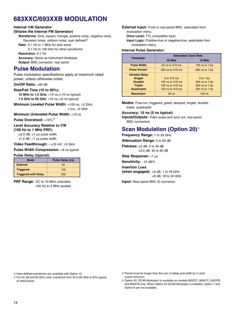
Mode Pulse Delay (ns)
External 50
Triggered 100
Triggered with Delay 200
ParameterSelectable Clock Rate
40 MHz 10 MHz
Pulse Width 25 ns to 419 ms 100 ns to 1.6s
Pulse Period➇ 250 ns to 419 ms 600 ns to 1.6s
Variable DelaySingletDoubletTriplet
Quadruplet
0 to 419 ms100 ns to 419 ms100 ns to 419 ms100 ns to 419 ms
0 to 1.6s300 ns to 1.6s300 ns to 1.6s300 ns to 1.6s
Resolution 25 ns 100 ns
15
DIGITAL DOWNCONVERTER SPECIFICATIONS (OPTION 21)
RF OutputFrequency: 10-2200 MHz
Maximum Leveled Output Power: +13 dBm, typically +19 dBm
Spectral PurityAll specifications apply at +10 dBm output, unless otherwise noted.
Harmonic and Harmonic Related:-40 dBc, ≤100 MHz-50 dBc, >100 MHz
Non-Harmonic Spurious-60 dBc
AM Noise:Typically -145 dBm/Hz at 0 dBm output and offsets >5 MHzfrom carrier.
Power Line and Fan-Related Spurious (dBc):
Pulse ModulationOn/Off Ratio: >80 dB
Minimum Leveled Pulse Width: 1 µsec
Level Accuracy Relative to CW (100 Hz to 500 kHz PRF): ± 0.5 dB
*Typical
Frequency RangeOffset from Carrier
<300 Hz ≥300 Hz
≥10 MHz to ≤500 MHz -68 -72
>500 MHz to ≤1050 MHz -62 -72
>1050 MHz to ≤2200 MHz -56 -66
FrequencyRange
Rise and FallTime Overshoot Width
CompressionVideo
Feedthrough
>500 to ≤2200 MHz
15 ns 10% 12 ns* ±15 mV*
>125 to ≤500 MHz
<33 ns* <11%* <12 ns* ±70 mV*
>31.25 to ≤125 MHz
<90 ns* <22%* <12 ns* ±130 mV*
≥10 to ≤31.25 MHz
<400 ns* <33%* <40 ns* ±70 mV*
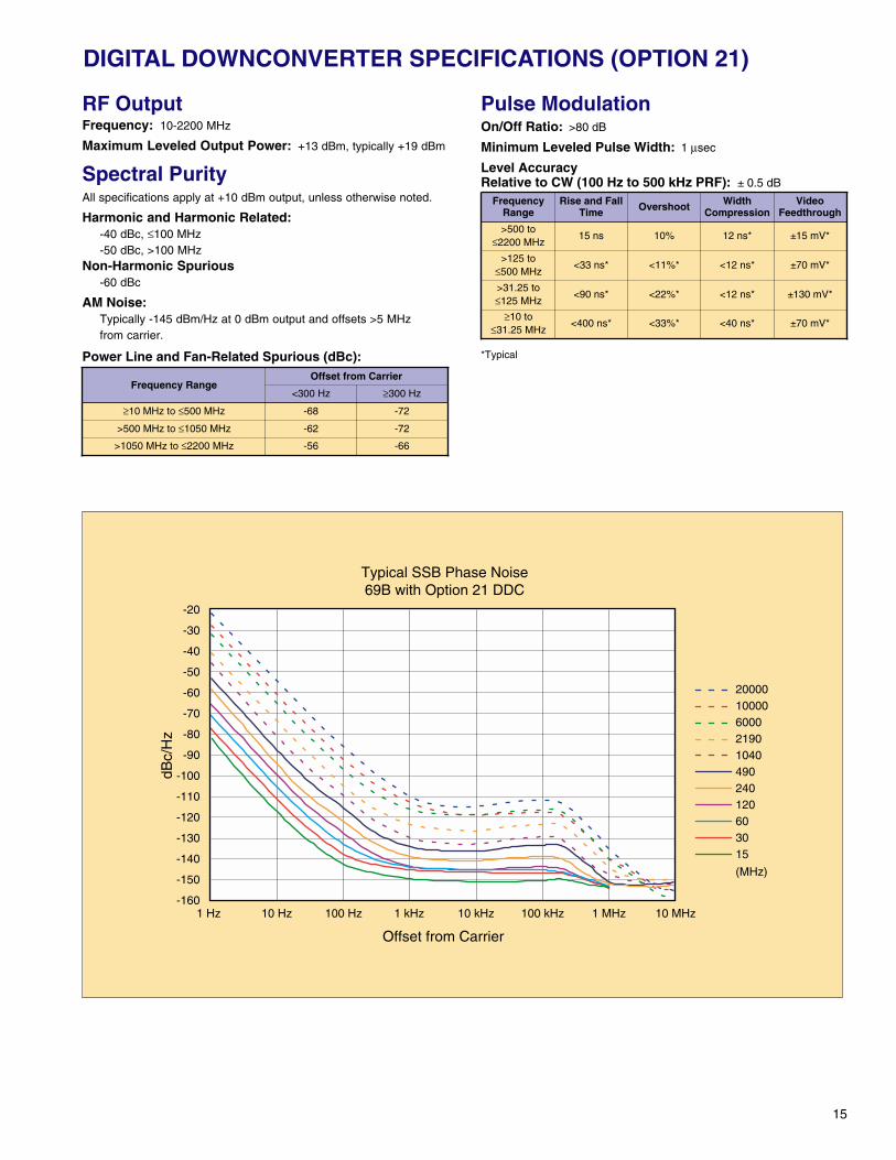
Typical SSB Phase Noise69B with Option 21 DDC
Offset from Carrier
-20
-160
-150
-140
-130
-120
-110
-100
-90
-80
-70
-60
-50
-40
-30
dBc/
Hz
1 Hz 10 Hz 100 Hz 1 kHz 10 kHz 100 kHz 1 MHz 10 MHz
2000010000600021901040490240120603015
(MHz)
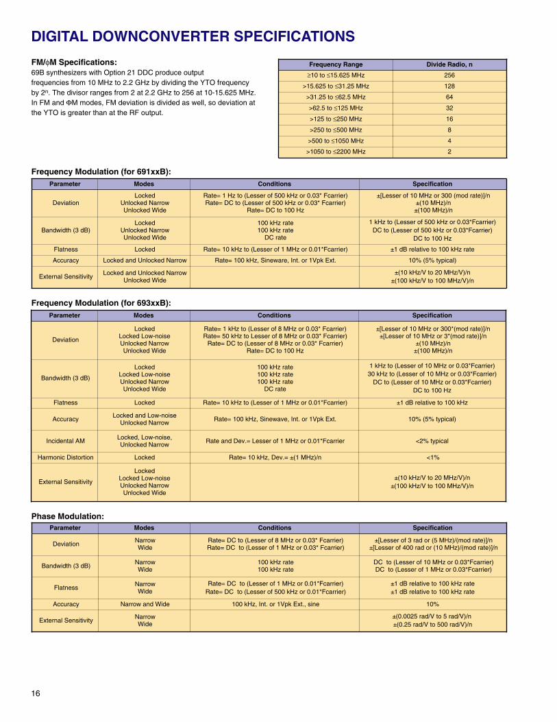
FM/φM Specifications:69B synthesizers with Option 21 DDC produce outputfrequencies from 10 MHz to 2.2 GHz by dividing the YTO frequencyby 2n. The divisor ranges from 2 at 2.2 GHz to 256 at 10-15.625 MHz.In FM and ΦM modes, FM deviation is divided as well, so deviation atthe YTO is greater than at the RF output.
Frequency Modulation (for 691xxB):
Frequency Modulation (for 693xxB):
Phase Modulation:
16
DIGITAL DOWNCONVERTER SPECIFICATIONS
Parameter Modes Conditions Specification
Deviation
LockedLocked Low-noiseUnlocked NarrowUnlocked Wide
Rate= 1 kHz to (Lesser of 8 MHz or 0.03* Fcarrier)Rate= 50 kHz to Lesser of 8 MHz or 0.03* Fcarrier)
Rate= DC to (Lesser of 8 MHz or 0.03* Fcarrier)Rate= DC to 100 Hz
±[Lesser of 10 MHz or 300*(mod rate)]/n±[Lesser of 10 MHz or 3*(mod rate)]/n
±(10 MHz)/n±(100 MHz)/n
Bandwidth (3 dB)
LockedLocked Low-noiseUnlocked NarrowUnlocked Wide
100 kHz rate100 kHz rate100 kHz rate
DC rate
1 kHz to (Lesser of 10 MHz or 0.03*Fcarrier)30 kHz to (Lesser of 10 MHz or 0.03*Fcarrier)
DC to (Lesser of 10 MHz or 0.03*Fcarrier)DC to 100 Hz
Flatness Locked Rate= 10 kHz to (Lesser of 1 MHz or 0.01*Fcarrier) ±1 dB relative to 100 kHz
Accuracy Locked and Low-noiseUnlocked Narrow Rate= 100 kHz, Sinewave, Int. or 1Vpk Ext. 10% (5% typical)
Incidental AM Locked, Low-noise,Unlocked Narrow Rate and Dev.= Lesser of 1 MHz or 0.01*Fcarrier <2% typical
Harmonic Distortion Locked Rate= 10 kHz, Dev.= ±(1 MHz)/n <1%
External Sensitivity
LockedLocked Low-noiseUnlocked NarrowUnlocked Wide
±(10 kHz/V to 20 MHz/V)/n±(100 kHz/V to 100 MHz/V)/n
Parameter Modes Conditions Specification
Deviation NarrowWide
Rate= DC to (Lesser of 8 MHz or 0.03* Fcarrier)Rate= DC to (Lesser of 1 MHz or 0.03* Fcarrier)
±[Lesser of 3 rad or (5 MHz)/(mod rate)]/n±[Lesser of 400 rad or (10 MHz)/(mod rate)]/n
Bandwidth (3 dB) NarrowWide
100 kHz rate100 kHz rate
DC to (Lesser of 10 MHz or 0.03*Fcarrier)DC to (Lesser of 1 MHz or 0.03*Fcarrier)
Flatness NarrowWide
Rate= DC to (Lesser of 1 MHz or 0.01*Fcarrier)Rate= DC to (Lesser of 500 kHz or 0.01*Fcarrier)
±1 dB relative to 100 kHz rate±1 dB relative to 100 kHz rate
Accuracy Narrow and Wide 100 kHz, Int. or 1Vpk Ext., sine 10%
External Sensitivity NarrowWide
±(0.0025 rad/V to 5 rad/V)/n±(0.25 rad/V to 500 rad/V)/n
Frequency Range Divide Radio, n
≥10 to ≤15.625 MHz 256
>15.625 to ≤31.25 MHz 128
>31.25 to ≤62.5 MHz 64
>62.5 to ≤125 MHz 32
>125 to ≤250 MHz 16
>250 to ≤500 MHz 8
>500 to ≤1050 MHz 4
>1050 to ≤2200 MHz 2
Parameter Modes Conditions Specification
DeviationLocked
Unlocked NarrowUnlocked Wide
Rate= 1 Hz to (Lesser of 500 kHz or 0.03* Fcarrier)Rate= DC to (Lesser of 500 kHz or 0.03* Fcarrier)
Rate= DC to 100 Hz
±[Lesser of 10 MHz or 300 (mod rate)]/n±(10 MHz)/n
±(100 MHz)/n
Bandwidth (3 dB)Locked
Unlocked NarrowUnlocked Wide
100 kHz rate100 kHz rate
DC rate
1 kHz to (Lesser of 500 kHz or 0.03*Fcarrier)DC to (Lesser of 500 kHz or 0.03*Fcarrier)
DC to 100 Hz
Flatness Locked Rate= 10 kHz to (Lesser of 1 MHz or 0.01*Fcarrier) ±1 dB relative to 100 kHz rate
Accuracy Locked and Unlocked Narrow Rate= 100 kHz, Sineware, Int. or 1Vpk Ext. 10% (5% typical)
External Sensitivity Locked and Unlocked NarrowUnlocked Wide
±(10 kHz/V to 20 MHz/V)/n±(100 kHz/V to 100 MHz/V)/n
17
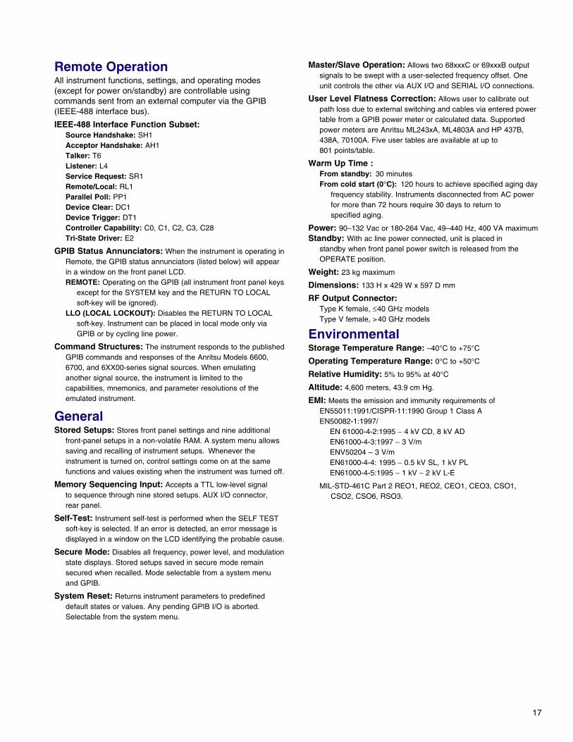
Remote OperationAll instrument functions, settings, and operating modes(except for power on/standby) are controllable usingcommands sent from an external computer via the GPIB(IEEE-488 interface bus).
IEEE-488 Interface Function Subset:Source Handshake: SH1Acceptor Handshake: AH1Talker: T6Listener: L4Service Request: SR1Remote/Local: RL1Parallel Poll: PP1Device Clear: DC1Device Trigger: DT1Controller Capability: C0, C1, C2, C3, C28Tri-State Driver: E2
GPIB Status Annunciators: When the instrument is operating inRemote, the GPIB status annunciators (listed below) will appearin a window on the front panel LCD.REMOTE: Operating on the GPIB (all instrument front panel keys
except for the SYSTEM key and the RETURN TO LOCALsoft-key will be ignored).
LLO (LOCAL LOCKOUT): Disables the RETURN TO LOCALsoft-key. Instrument can be placed in local mode only viaGPIB or by cycling line power.
Command Structures: The instrument responds to the publishedGPIB commands and responses of the Anritsu Models 6600,6700, and 6XX00-series signal sources. When emulatinganother signal source, the instrument is limited to thecapabilities, mnemonics, and parameter resolutions of theemulated instrument.
GeneralStored Setups: Stores front panel settings and nine additional
front-panel setups in a non-volatile RAM. A system menu allowssaving and recalling of instrument setups. Whenever theinstrument is turned on, control settings come on at the samefunctions and values existing when the instrument was turned off.
Memory Sequencing Input: Accepts a TTL low-level signalto sequence through nine stored setups. AUX I/O connector,rear panel.
Self-Test: Instrument self-test is performed when the SELF TESTsoft-key is selected. If an error is detected, an error message isdisplayed in a window on the LCD identifying the probable cause.
Secure Mode: Disables all frequency, power level, and modulationstate displays. Stored setups saved in secure mode remainsecured when recalled. Mode selectable from a system menuand GPIB.
System Reset: Returns instrument parameters to predefineddefault states or values. Any pending GPIB I/O is aborted.Selectable from the system menu.
Master/Slave Operation: Allows two 68xxxC or 69xxxB outputsignals to be swept with a user-selected frequency offset. Oneunit controls the other via AUX I/O and SERIAL I/O connections.
User Level Flatness Correction: Allows user to calibrate outpath loss due to external switching and cables via entered powertable from a GPIB power meter or calculated data. Supportedpower meters are Anritsu ML243xA, ML4803A and HP 437B,438A, 70100A. Five user tables are available at up to801 points/table.
Warm Up Time :From standby: 30 minutesFrom cold start (0°C): 120 hours to achieve specified aging day
frequency stability. Instruments disconnected from AC powerfor more than 72 hours require 30 days to return tospecified aging.
Power: 90−132 Vac or 180-264 Vac, 49–440 Hz, 400 VA maximumStandby: With ac line power connected, unit is placed in
standby when front panel power switch is released from theOPERATE position.
Weight: 23 kg maximum
Dimensions: 133 H x 429 W x 597 D mm
RF Output Connector:Type K female, ≤40 GHz modelsType V female, >40 GHz models
EnvironmentalStorage Temperature Range: –40°C to +75°C
Operating Temperature Range: 0°C to +50°C
Relative Humidity: 5% to 95% at 40°C
Altitude: 4,600 meters, 43.9 cm Hg.
EMI: Meets the emission and immunity requirements ofEN55011:1991/CISPR-11:1990 Group 1 Class A EN50082-1:1997/
EN 61000-4-2:1995 − 4 kV CD, 8 kV ADEN61000-4-3:1997 − 3 V/mENV50204 – 3 V/mEN61000-4-4: 1995 − 0.5 kV SL, 1 kV PLEN61000-4-5:1995 − 1 kV − 2 kV L-E
MIL-STD-461C Part 2 REO1, REO2, CEO1, CEO3, CSO1,CSO2, CSO6, RSO3.
18
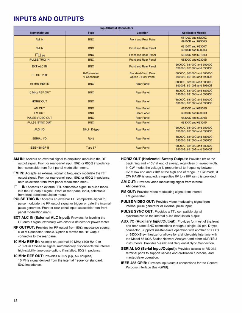
INPUTS AND OUTPUTS
AM IN: Accepts an external signal to amplitude modulate the RFoutput signal. Front or rear-panel input, 50Ω or 600Ω impedance,both selectable from front-panel modulation menu.
FM IN: Accepts an external signal to frequency modulate the RFoutput signal. Front or rear-panel input, 50Ω or 600Ω impedance,both selectable from front-panel modulation menu.
IN: Accepts an external TTL compatible signal to pulse modu-late the RF output signal. Front or rear-panel input, selectablefrom front-panel modulation menu.
PULSE TRIG IN: Accepts an external TTL compatible signal topulse modulate the RF output signal or trigger or gate the internalpulse generator. Front or rear-panel input, selectable from front-panel modulation menu.
EXT ALC IN (External ALC Input): Provides for leveling theRF output signal externally with either a detector or power meter.
RF OUTPUT: Provides for RF output from 50Ω impedance source.K or V Connector, female. Option 9 moves the RF Outputconnector to the rear panel.
10 MHz REF IN: Accepts an external 10 MHz ±100 Hz, 0 to+10 dBm time-base signal. Automatically disconnects the internalhigh-stability time-base option, if installed. 50Ω impedance.
10 MHz REF OUT: Provides a 0.5V p-p, AC coupled, 10 MHz signal derived from the internal frequency standard.50Ω impedance.
HORIZ OUT (Horizontal Sweep Output): Provides 0V at thebeginning and +10V at end of sweep, regardless of sweep width.In CW mode, the voltage is proportional to frequency between0V at low end and +10V at the high end of range. In CW mode, ifCW RAMP is enabled, a repetitive 0V to +10V ramp is provided.
AM OUT: Provides video modulating signal from internalAM generator.
FM OUT: Provides video modulating signal from internalFM generator.
PULSE VIDEO OUT: Provides video modulating signal frominternal pulse generator or external pulse input.
PULSE SYNC OUT: Provides a TTL compatible signalsynchronized to the internal pulse modulation output.
AUX I/O (Auxiliary Input/Output): Provides for most of the frontand rear panel BNC connections through a single, 25-pin, D-typeconnector. Supports master-slave operation with another 68XXXCor 69XXXB synthesizer or allows for a single-cable interface withthe Model 56100A Scalar Network Analyzer and other ANRITSUinstruments. Provides V/GHz and Sequential Sync Connection.
SERIAL I/O (Serial Input/Output): Provides access to RS-232terminal ports to support service and calibration functions, andmaster/slave operation.
IEEE-488 GPIB: Provides input/output connections for the GeneralPurpose Interface Bus (GPIB).
Input/Output Connectors
Nomenclature Type Location Applicable Models
AM IN BNC Front and Rear Pane68100C and 68300C69100B and 69300B
FM IN BNC Front and Rear Panel68100C and 68300C69100B and 69300B
IN BNC Front and Rear Panel 68100C and 69100B
PULSE TRIG IN BNC Front and Rear Panel 68300C and 69300B
EXT ALC IN BNC Front and Rear Panel68000C, 68100C and 68300C69000B, 69100B and 69300B
RF OUTPUTK-ConnectorV-Connector
Standard-Front PaneOption 9-Rear Panel
68000C, 68100C and 68300C69000B, 69100B and 69300B
10 MHz REF IN BNC Rear Panel68000C, 68100C and 68300C69000B, 69100B and 69300B
10 MHz REF OUT BNC Rear Panel68000C, 68100C and 68300C69000B, 69100B and 69300B
HORIZ OUT BNC Rear Panel68000C, 68100C and 68300C69000B, 69100B and 69300B
AM OUT BNC Rear Panel 68300C and 69300B
FM OUT BNC Rear Panel 68300C and 69300B
PULSE VIDEO OUT BNC Rear Panel 68300C and 69300B
PULSE SYNC OUT BNC Rear Panel 68300C and 69300B
AUX I/O 25-pin D-type Rear Panel68000C, 68100C and 68300C69000B, 69100B and 69300B
SERIAL I/O RJ45 Rear Panel68000C, 68100C and 68300C69000B, 69100B and 69300B
IEEE-488 GPIB Type 57 Rear Panel68000C, 68100C and 68300C69000B, 69100B and 69300B
19
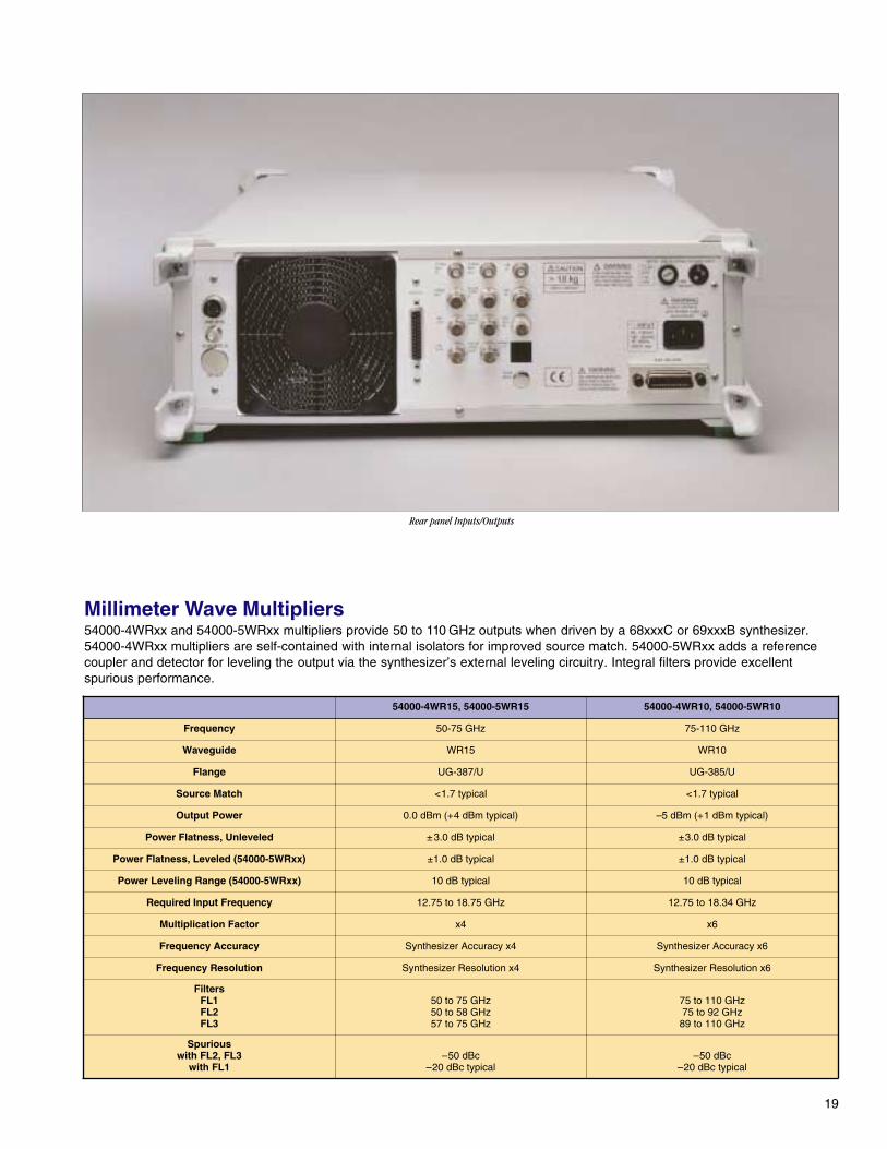
Millimeter Wave Multipliers54000-4WRxx and 54000-5WRxx multipliers provide 50 to 110 GHz outputs when driven by a 68xxxC or 69xxxB synthesizer.54000-4WRxx multipliers are self-contained with internal isolators for improved source match. 54000-5WRxx adds a referencecoupler and detector for leveling the output via the synthesizer’s external leveling circuitry. Integral filters provide excellentspurious performance.
Rear panel Inputs/Outputs
54000-4WR15, 54000-5WR15 54000-4WR10, 54000-5WR10
Frequency 50-75 GHz 75-110 GHz
Waveguide WR15 WR10
Flange UG-387/U UG-385/U
Source Match <1.7 typical <1.7 typical
Output Power 0.0 dBm (+4 dBm typical) –5 dBm (+1 dBm typical)
Power Flatness, Unleveled ±3.0 dB typical ±3.0 dB typical
Power Flatness, Leveled (54000-5WRxx) ±1.0 dB typical ±1.0 dB typical
Power Leveling Range (54000-5WRxx) 10 dB typical 10 dB typical
Required Input Frequency 12.75 to 18.75 GHz 12.75 to 18.34 GHz
Multiplication Factor x4 x6
Frequency Accuracy Synthesizer Accuracy x4 Synthesizer Accuracy x6
Frequency Resolution Synthesizer Resolution x4 Synthesizer Resolution x6
FiltersFL1FL2FL3
50 to 75 GHz50 to 58 GHz57 to 75 GHz
75 to 110 GHz75 to 92 GHz
89 to 110 GHz
Spuriouswith FL2, FL3
with FL1–50 dBc
–20 dBc typical–50 dBc
–20 dBc typical
20
ModelsSynthesized CW Generators
68017C, 0.01 to 8.4 GHz 69017B, 0.01 to 8.4 GHz68037C, 2 to 20 GHz 69037B, 2 to 20 GHz68047C, 0.01 to 20 GHz 69047B, 0.01 to 20 GHz68067C, 0.01 to 40 GHz 69067B, 0.01 to 40 GHz68077C, 0.01 to 50 GHz 69077B, 0.01 to 50 GHz68087C, 0.01 to 60 GHz 69087B, 0.01 to 60 GHz68097C, 0.01 to 65 GHz 69097B, 0.01 to 65 GHz
Synthesized Signal Generators68117C, 0.01 to 8.4 GHz 69117B, 0.01 to 8.4 GHz68137C, 2 to 20 GHz 69137B, 2 to 20 GHz68147C, 0.01 to 20 GHz 69147B, 0.01 to 20 GHz68167C, 0.01 to 40 GHz 69167B, 0.01 to 40 GHz68177C, 0.01 to 50 GHz 69177B, 0.01 to 50 GHz68187C, 0.01 to 60 GHz 69187B, 0.01 to 60 GHz68197C, 0.01 to 65 GHz 69197B, 0.01 to 65 GHz
Synthesized High Performance Signal Generators68317C, 0.01 to 8.4 GHz 69317B, 0.01 to 8.4 GHz68337C, 2 to 20 GHz 69337B, 2 to 20 GHz68347C, 0.01 to 20 GHz 69347B, 0.01 to 20 GHz68367C, 0.01 to 40 GHz 69367B, 0.01 to 40 GHz68377C, 0.01 to 50 GHz 69377B, 0.01 to 50 GHz68387C, 0.01 to 60 GHz 69387B, 0.01 to 60 GHz68397C, 0.01 to 65 GHz 69397B, 0.01 to 65 GHz
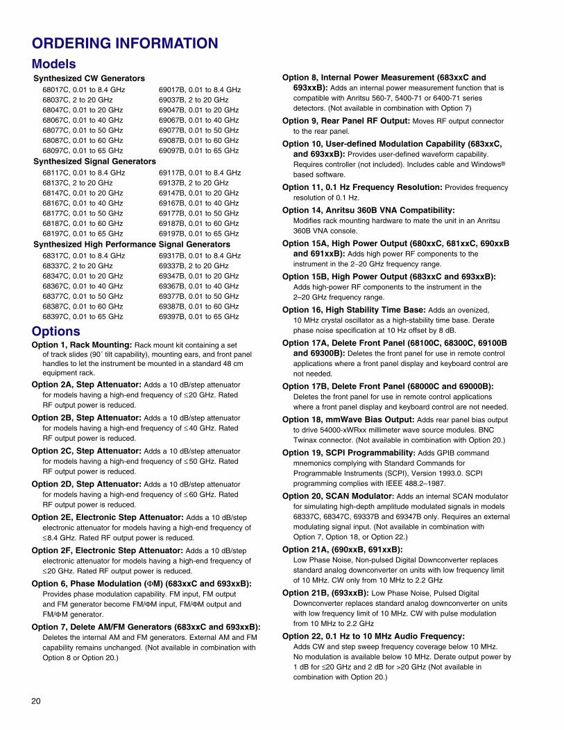
OptionsOption 1, Rack Mounting: Rack mount kit containing a set
of track slides (90˚ tilt capability), mounting ears, and front panelhandles to let the instrument be mounted in a standard 48 cmequipment rack.
Option 2A, Step Attenuator: Adds a 10 dB/step attenuatorfor models having a high-end frequency of ≤20 GHz. RatedRF output power is reduced.
Option 2B, Step Attenuator: Adds a 10 dB/step attenuatorfor models having a high-end frequency of ≤ 40 GHz. RatedRF output power is reduced.
Option 2C, Step Attenuator: Adds a 10 dB/step attenuatorfor models having a high-end frequency of ≤ 50 GHz. RatedRF output power is reduced.
Option 2D, Step Attenuator: Adds a 10 dB/step attenuatorfor models having a high-end frequency of ≤ 60 GHz. RatedRF output power is reduced.
Option 2E, Electronic Step Attenuator: Adds a 10 dB/stepelectronic attenuator for models having a high-end frequency of≤8.4 GHz. Rated RF output power is reduced.
Option 2F, Electronic Step Attenuator: Adds a 10 dB/stepelectronic attenuator for models having a high-end frequency of≤20 GHz. Rated RF output power is reduced.
Option 6, Phase Modulation (ΦM) (683xxC and 693xxB):Provides phase modulation capability. FM input, FM outputand FM generator become FM/ΦM input, FM/ΦM output andFM/ΦM generator.
Option 7, Delete AM/FM Generators (683xxC and 693xxB):Deletes the internal AM and FM generators. External AM and FMcapability remains unchanged. (Not available in combination withOption 8 or Option 20.)
Option 8, Internal Power Measurement (683xxC and693xxB): Adds an internal power measurement function that iscompatible with Anritsu 560-7, 5400-71 or 6400-71 seriesdetectors. (Not available in combination with Option 7)
Option 9, Rear Panel RF Output: Moves RF output connectorto the rear panel.
Option 10, User-defined Modulation Capability (683xxC,and 693xxB): Provides user-defined waveform capability.Requires controller (not included). Includes cable and Windows®
based software.
Option 11, 0.1 Hz Frequency Resolution: Provides frequencyresolution of 0.1 Hz.
Option 14, Anritsu 360B VNA Compatibility:Modifies rack mounting hardware to mate the unit in an Anritsu360B VNA console.
Option 15A, High Power Output (680xxC, 681xxC, 690xxBand 691xxB): Adds high power RF components to theinstrument in the 2−20 GHz frequency range.
Option 15B, High Power Output (683xxC and 693xxB):Adds high-power RF components to the instrument in the2–20 GHz frequency range.
Option 16, High Stability Time Base: Adds an ovenized,10 MHz crystal oscillator as a high-stability time base. Deratephase noise specification at 10 Hz offset by 8 dB.
Option 17A, Delete Front Panel (68100C, 68300C, 69100Band 69300B): Deletes the front panel for use in remote controlapplications where a front panel display and keyboard control arenot needed.
Option 17B, Delete Front Panel (68000C and 69000B):Deletes the front panel for use in remote control applicationswhere a front panel display and keyboard control are not needed.
Option 18, mmWave Bias Output: Adds rear panel bias outputto drive 54000-xWRxx millimeter wave source modules. BNCTwinax connector. (Not available in combination with Option 20.)
Option 19, SCPI Programmability: Adds GPIB commandmnemonics complying with Standard Commands forProgrammable Instruments (SCPI), Version 1993.0. SCPIprogramming complies with IEEE 488.2–1987.
Option 20, SCAN Modulator: Adds an internal SCAN modulatorfor simulating high-depth amplitude modulated signals in models68337C, 68347C, 69337B and 69347B only. Requires an externalmodulating signal input. (Not available in combination withOption 7, Option 18, or Option 22.)
Option 21A, (690xxB, 691xxB): Low Phase Noise, Non-pulsed Digital Downconverter replacesstandard analog downconverter on units with low frequency limitof 10 MHz. CW only from 10 MHz to 2.2 GHz
Option 21B, (693xxB): Low Phase Noise, Pulsed DigitalDownconverter replaces standard analog downconverter on unitswith low frequency limit of 10 MHz. CW with pulse modulationfrom 10 MHz to 2.2 GHz
Option 22, 0.1 Hz to 10 MHz Audio Frequency:Adds CW and step sweep frequency coverage below 10 MHz.No modulation is available below 10 MHz. Derate output power by1 dB for ≤20 GHz and 2 dB for >20 GHz (Not available incombination with Option 20.)
ORDERING INFORMATION
21
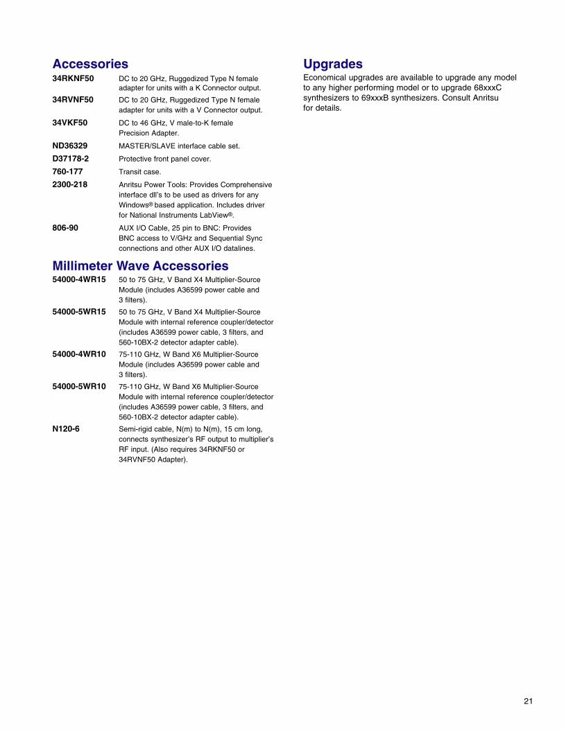
Accessories34RKNF50 DC to 20 GHz, Ruggedized Type N female
adapter for units with a K Connector output.
34RVNF50 DC to 20 GHz, Ruggedized Type N femaleadapter for units with a V Connector output.
34VKF50 DC to 46 GHz, V male-to-K femalePrecision Adapter.
ND36329 MASTER/SLAVE interface cable set.
D37178-2 Protective front panel cover.
760-177 Transit case.
2300-218 Anritsu Power Tools: Provides Comprehensiveinterface dll’s to be used as drivers for anyWindows® based application. Includes driverfor National Instruments LabView®.
806-90 AUX I/O Cable, 25 pin to BNC: ProvidesBNC access to V/GHz and Sequential Syncconnections and other AUX I/O datalines.
Millimeter Wave Accessories54000-4WR15 50 to 75 GHz, V Band X4 Multiplier-Source
Module (includes A36599 power cable and3 filters).
54000-5WR15 50 to 75 GHz, V Band X4 Multiplier-SourceModule with internal reference coupler/detector(includes A36599 power cable, 3 filters, and 560-10BX-2 detector adapter cable).
54000-4WR10 75-110 GHz, W Band X6 Multiplier-SourceModule (includes A36599 power cable and3 filters).
54000-5WR10 75-110 GHz, W Band X6 Multiplier-SourceModule with internal reference coupler/detector(includes A36599 power cable, 3 filters, and 560-10BX-2 detector adapter cable).
N120-6 Semi-rigid cable, N(m) to N(m), 15 cm long,connects synthesizer’s RF output to multiplier’sRF input. (Also requires 34RKNF50 or34RVNF50 Adapter).
UpgradesEconomical upgrades are available to upgrade any modelto any higher performing model or to upgrade 68xxxCsynthesizers to 69xxxB synthesizers. Consult Anritsufor details.
22
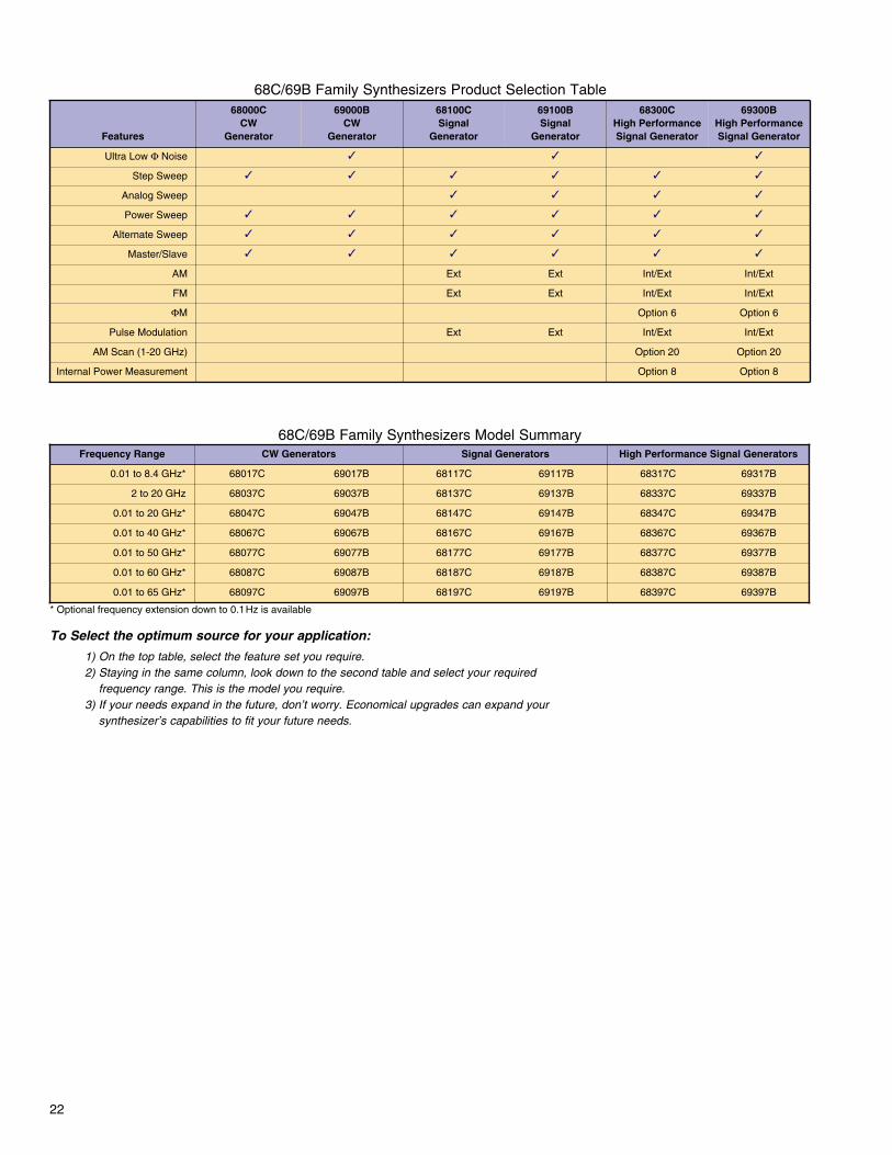
68C/69B Family Synthesizers Model Summary
68C/69B Family Synthesizers Product Selection Table
* Optional frequency extension down to 0.1Hz is available
To Select the optimum source for your application:
1) On the top table, select the feature set you require.2) Staying in the same column, look down to the second table and select your required
frequency range. This is the model you require.3) If your needs expand in the future, don’t worry. Economical upgrades can expand your
synthesizer’s capabilities to fit your future needs.
Features
68000CCW
Generator
69000BCW
Generator
68100CSignal
Generator
69100BSignal
Generator
68300CHigh PerformanceSignal Generator
69300BHigh PerformanceSignal Generator
Ultra Low Φ Noise
Step Sweep
Analog Sweep
Power Sweep
Alternate Sweep
Master/Slave
AM Ext Ext Int/Ext Int/Ext
FM Ext Ext Int/Ext Int/Ext
ΦM Option 6 Option 6
Pulse Modulation Ext Ext Int/Ext Int/Ext
AM Scan (1-20 GHz) Option 20 Option 20
Internal Power Measurement Option 8 Option 8
Frequency Range CW Generators Signal Generators High Performance Signal Generators
0.01 to 8.4 GHz* 68017C 69017B 68117C 69117B 68317C
2 to 20 GHz 68037C 69037B 68137C 69137B 68337C
0.01 to 20 GHz* 68047C 69047B 68147C 69147B 68347C
0.01 to 40 GHz* 68067C 69067B 68167C 69167B 68367C
0.01 to 50 GHz* 68077C 69077B 68177C 69177B 68377C
0.01 to 60 GHz* 68087C 69087B 68187C 69187B 68387C
69317B
69337B
69347B
69367B
69377B
69387B
0.01 to 65 GHz* 68097C 69097B 68197C 69197B 68397C 69397B


Windows is a registered trademark of Microsoft Corporation.
LabVIEW is a registered trademark of National Instruments.
September, 2000; Rev: C 11410-00211Data subject to change without notice 68C/69B Synthesizers Data Sheet /GIP-E
Sales Centers:US (800) ANRITSUCanada (800) ANRITSUSouth America 55 (21) 286-9141
Sales Centers:Europe 44 (01582) 433200Japan 81 (03) 3446-1111Asia-Pacific 65-2822400
Microwave Measurements Division 490 Jarvis Drive Morgan Hill, CA 95037-2809http://www.us.anritsu.com FAX (408) 778-0239