MICROWAVE SIGNAL PROPAGATION ON OIL PALM …s2is.org/Issues/v4/n3/papers/paper4.pdf · MICROWAVE...
14
MICROWAVE SIGNAL PROPAGATION ON OIL PALM TREES: MEASUREMENTS AND ANALYSIS 1 Z. I. Rizman, 2 K. Jusoff, 1 S. S. Rais, 1 H. H. H. Bakar, 3 G. K. S. Nair, 4 Y. K. Ho 1 Faculty of Electrical Engineering Universiti Teknologi MARA (UiTM) Terengganu Dungun Branch, 23000 Dungun, Terengganu, Malaysia 2 TropAir, Faculty of Forestry Universiti Putra Malaysia, 43400 UPM Serdang, Selangor, Malaysia 3 Academy of Language Studies Universiti Teknologi MARA (UiTM) Terengganu Dungun Branch, 23000 Dungun, Terengganu, Malaysia 4 Faculty of Engineering and Green Technology Tunku Abdul Rahman University, Jalan Universiti, Bandar Barat, 31900 Kampar, Perak, Malaysia Emails: [email protected] , [email protected] , [email protected] , [email protected] , [email protected] , [email protected] Submitted: July 8, 2011 Accepted: August 16, 2011 Published: September 1, 2011 INTERNATIONAL JOURNAL ON SMART SENSING AND INTELLIGENT SYSTEMS VOL. 4, NO. 3, SEPTEMBER 2011 388
Transcript of MICROWAVE SIGNAL PROPAGATION ON OIL PALM …s2is.org/Issues/v4/n3/papers/paper4.pdf · MICROWAVE...

MICROWAVE SIGNAL PROPAGATION ON OIL PALM
TREES: MEASUREMENTS AND ANALYSIS
1Z. I. Rizman, 2K. Jusoff, 1S. S. Rais, 1H. H. H. Bakar, 3G. K. S. Nair, 4Y. K. Ho
1Faculty of Electrical Engineering
Universiti Teknologi MARA (UiTM) Terengganu Dungun Branch, 23000
Dungun, Terengganu, Malaysia 2TropAir, Faculty of Forestry
Universiti Putra Malaysia, 43400
UPM Serdang, Selangor, Malaysia 3Academy of Language Studies
Universiti Teknologi MARA (UiTM) Terengganu Dungun Branch, 23000
Dungun, Terengganu, Malaysia 4Faculty of Engineering and Green Technology
Tunku Abdul Rahman University, Jalan Universiti, Bandar Barat, 31900
Kampar, Perak, Malaysia
Emails: [email protected], [email protected], [email protected],
[email protected], [email protected], [email protected]
Submitted: July 8, 2011 Accepted: August 16, 2011 Published: September 1, 2011
INTERNATIONAL JOURNAL ON SMART SENSING AND INTELLIGENT SYSTEMS VOL. 4, NO. 3, SEPTEMBER 2011
388

Abstract- This paper presents the study of microwave signal attenuation on oil palm trees at 0.9 GHz,
1.8 GHz and 2.3 GHz frequencies. The main objective is to investigate the characteristics of
propagation phenomenon by analysing the received signal strength. The experiments were made at the
estate where there are straight line uniform canopies of mature oil palm trees. The measurements were
carried out on the same transmission paths with different number of trees and height at trunk, leaves
and fruits which obstructing the signal paths. The results have shown that excessive attenuation is due
to scattering, depolarisation, fluctuation and absorption. It is strongly aggrees with the previous studies.
Further studies on other types of vegetation and environments, and its seasonal differences are
important as future research.
Index terms: Attenuation, frequency, microwave, oil palm tree, propagation.
I. INTRODUCTION
Attenuation is the signal reduction in radio systems [1]. The degradation of received signal
strengths suffered by the radio waves is caused by the excess propagation loss. It is due to the
presence of trees along a radio path [2, 3, 4, 9, 13].
There are many factors in terms of parameters and variations involved in the attenuation, one of it
is trees. The tree can be considered as a random medium which consists of many dielectric
objects such as trunk, leaves, fronds, twigs, branches etc. These tree constituents attenuate and
scatter an incident electromagnetic field. The extent of scattering depends on the canopy particle
size, height, density, type of tree species, location, moisture content, signal frequency,
polarization etc [19]. The attenuation can be external and internal. Dense large leaves at the end
of branches are the dominant contributor for attenuating microwave signals [3, 7, 11, 12].
The oil palm tree is selected as a sample of the measurements to evaluate the signal propagation
loss through vegetation. It is one of very famous type of trees in Malaysia. The oil palm tree has a
distinct shape and looks like a sphere which consist of the trunk, leaves and fronds. The tree has
leaves which are distributed around the axis very accurately and they are on the top of the trunk
[8].
The purpose of this paper is to obtain information on the propagation phenomenon of microwave
signals through oil palm trees. The main objective is to measure and analyze the strength of
Z. I. Rizman, K. Jusoff, S. S. Rais, H. H. H. Bakar, G. K. S. Nair, Y. K. Ho, Microwave Signal Propagation on Oil Palm Trees: Measurements And Analysis
389

received signals in different frequencies. The additional objective is to determine oil palm tree
attenuation caused by shadowing with respect to line of sight on a basis of the received signal
versus number of trees and received signal versus distances.
II. YAGI UDA ANTENNA
An antenna is used in transmitting or receiving radio waves in a telecommunication system. The
size and the design of an antenna depends on the frequency or wavelength of the transmission or
reception radio waves, directivity, radiation mechanism, radiation pattern and polarization. The
type of antenna used for both transmitting and receiving radio waves are normally the same [14].
A Yagi Uda or Yagi antenna is commonly used and is very practical antenna. It has advantageous
features such as large gain, high directivity, cheap cost, low weight and uncomplicated profile.
The Yagi Uda antenna is a propagating wave antenna which consists of one or more dipoles
mounted on a crossbar. The dipoles are of different lengths and different frequencies used in
television broadcasting. Additional pieces of metal called directors and reflectors are placed on
the crossbar in front and the back of the dipoles. The directors and reflectors reflect and
concentrate the radio waves towards the directors. The Yagi Uda antenna is often mounted on a
rotating tower or base. So, it can easily be turned towards the source of the desired transmission.
The Yagi Uda antenna can radiate radio waves as both horizontal and vertical polarized signals,
as shown in Figure 1 [14].
Figure 1. Horizontal and vertical polarization of 4 Yagi elements
INTERNATIONAL JOURNAL ON SMART SENSING AND INTELLIGENT SYSTEMS VOL. 4, NO. 3, SEPTEMBER 2011
390

A transmitting antenna receives waves in the form of electrical signals. The electrical signals,
which is also known as radio frequency (RF) energy, flows from a transmitting station to the
transmitting antenna, and converts it to radio waves that travel in the free space. The antenna then
generates a magnetic field around it. Subsequently, the magnetic wave propagates towards and is
received by the receiving antenna where it induces a current. The receiving station converts the
electrical impulse to produce an output. The waves produced by the electrical signals in the
devices are called guided waves. The guided waves can propagate through the transmission lines
such as cables or wires. The waves that propagate in a space are known as free space waves. It
propagates through the air or outer space without using a transmission line. The receiving antenna
receives the free space waves and converts it to guided waves which are ultimately used to
produce an output [14].
The driven part of the antenna, as shown in Figure 2 below, drives the antenna and is connected
directly to the consumer devices. The other 2 outer elements namely, the reflector and the
director are known as parasitic elements. The reflector reflects the RF energy whilst the director
directs the RF energy. Normally, the driven is 5% shorter than the reflector and the driven is 5%
longer than the director. The middle element is the simple half wave dipole antenna [14].
Figure 2. Top view on 3 elements of Yagi beam
Z. I. Rizman, K. Jusoff, S. S. Rais, H. H. H. Bakar, G. K. S. Nair, Y. K. Ho, Microwave Signal Propagation on Oil Palm Trees: Measurements And Analysis
391
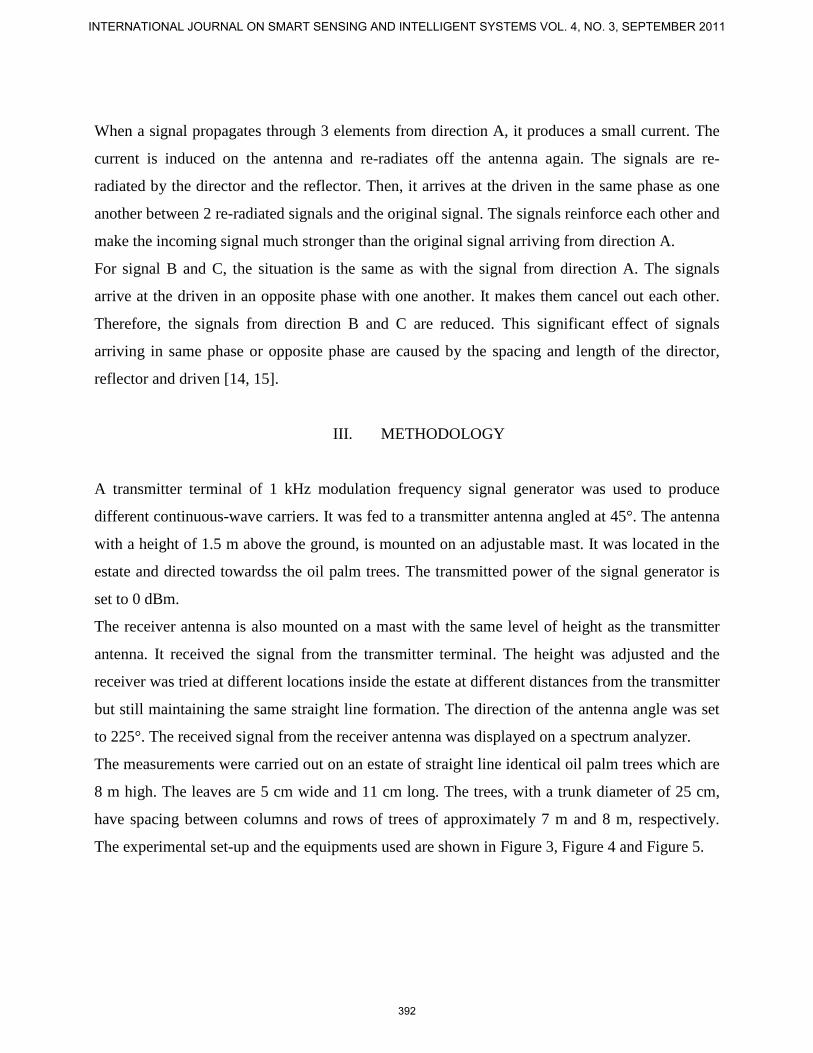
When a signal propagates through 3 elements from direction A, it produces a small current. The
current is induced on the antenna and re-radiates off the antenna again. The signals are re-
radiated by the director and the reflector. Then, it arrives at the driven in the same phase as one
another between 2 re-radiated signals and the original signal. The signals reinforce each other and
make the incoming signal much stronger than the original signal arriving from direction A.
For signal B and C, the situation is the same as with the signal from direction A. The signals
arrive at the driven in an opposite phase with one another. It makes them cancel out each other.
Therefore, the signals from direction B and C are reduced. This significant effect of signals
arriving in same phase or opposite phase are caused by the spacing and length of the director,
reflector and driven [14, 15].
III. METHODOLOGY
A transmitter terminal of 1 kHz modulation frequency signal generator was used to produce
different continuous-wave carriers. It was fed to a transmitter antenna angled at 45°. The antenna
with a height of 1.5 m above the ground, is mounted on an adjustable mast. It was located in the
estate and directed towardss the oil palm trees. The transmitted power of the signal generator is
set to 0 dBm.
The receiver antenna is also mounted on a mast with the same level of height as the transmitter
antenna. It received the signal from the transmitter terminal. The height was adjusted and the
receiver was tried at different locations inside the estate at different distances from the transmitter
but still maintaining the same straight line formation. The direction of the antenna angle was set
to 225°. The received signal from the receiver antenna was displayed on a spectrum analyzer.
The measurements were carried out on an estate of straight line identical oil palm trees which are
8 m high. The leaves are 5 cm wide and 11 cm long. The trees, with a trunk diameter of 25 cm,
have spacing between columns and rows of trees of approximately 7 m and 8 m, respectively.
The experimental set-up and the equipments used are shown in Figure 3, Figure 4 and Figure 5.
INTERNATIONAL JOURNAL ON SMART SENSING AND INTELLIGENT SYSTEMS VOL. 4, NO. 3, SEPTEMBER 2011
392

Yagi Udaantenna
Signalgenerator
Yagi Udaantenna
Spectrumanalyzer
ouputinput
Oil palm tree
Horizontalpolarization
Horizontalpolarization
Figure 3. Experimental set-up
Figure 4. Marconi 2024 9 kHz to 2.4 GHz signal generator
Figure 5. Agilent 8560E 30 Hz to 2.9 GHz spectrum analyzer
Z. I. Rizman, K. Jusoff, S. S. Rais, H. H. H. Bakar, G. K. S. Nair, Y. K. Ho, Microwave Signal Propagation on Oil Palm Trees: Measurements And Analysis
393

IV. MEASUREMENTS
Measurements were performed through the palm oil trees medium which focuses on the
propagation mechanisms generated by the vegetation element. It analyses the contribution of the
tree constituents namely, the trunk, fruits and leaves. The transmitter terminal was located inside
the estate at a fixed distance of about 4 m from the first line of trees and in the center of the line.
The received terminal was also placed inside the estate, at various positions, and usually such that
the line-of-sight followed one row of trees. For each test run, both transmitting and receiving
antennas were placed at equal heights above the ground where both antennas are pointing out to
each other, so that the line-of-sight followed a horizontal path with different levels of height. At
the 4 and 5 m heights, significant fruits and leaves were present and vegetation density was fairly
high while mostly trunk was exposed at the 1.5 m height. Between two trees, the measurements
were taken at three different receiver positions, i.e. at 2, 4, and 6 m from the first tree as shown in
Figure 6.
Figure 6. Transmitter and receiver positions in test site
: oil palm tree
P1, P2, P3 and P4 : receiver position
PX : transmitter position
INTERNATIONAL JOURNAL ON SMART SENSING AND INTELLIGENT SYSTEMS VOL. 4, NO. 3, SEPTEMBER 2011
394

V. RESULTS
Table 1: Received signal for different distances at frequency of 0.9 GHz
Distances
(m)
Received signal (dBm) Power level (pW)
trunk fruits leaves trunk fruits leaves
-6 -69.31 -71.58 -75.42 99.12 78.41 55.47
-4 -70.50 -72.33 -76.67 84.79 76.38 52.12
-2 -71.63 -73.49 -77.16 71.83 69.25 43.58
2 -72.14 -74.63 -77.63 56.27 45.17 23.48
4 -73.27 -75.18 -78.27 47.14 37.52 18.53
6 -75.38 -76.59 -78.91 39.58 23.64 14.82
10 -76.42 -77.12 -79.38 25.47 15.38 9.26
12 -77.33 -78.67 -79.83 18.24 10.79 8.57
14 -78.56 -79.38 -81.52 13.85 9.14 7.15
18 -78.34 -80.49 -83.45 9.98 7.26 5.37
20 -79.17 -81.67 -85.17 7.63 6.80 4.54
22 -81.59 -83.51 -86.72 5.41 5.37 3.69
26 -83.47 -85.24 -87.14 4.57 4.18 2.73
28 -85.33 -86.67 -88.83 3.98 3.04 2.15
30 -87.56 -88.31 -89.58 2.61 2.69 1.85
-92-88-84-80-76-72-68
1 2 3 4 5 6 7 8 9 10 11 12 13 14 15
Distances, m
Rec
eive
d si
gnal
, dB
m
trunk fruit leave
Figure 7. Received signal for different distances at frequency of 0.9 GHz
Z. I. Rizman, K. Jusoff, S. S. Rais, H. H. H. Bakar, G. K. S. Nair, Y. K. Ho, Microwave Signal Propagation on Oil Palm Trees: Measurements And Analysis
395

Table 2: Received signal for different distances at frequency of 1.8 GHz
Distance
(m)
Received signal (dBm) Power level (pW)
trunk fruits leaves trunk fruits leaves
-6 -81.47 -82.47 -83.65 7.49 6.39 5.31
-4 -82.30 -83.33 -84.83 6.56 5.21 4.64
-2 -83.59 -84.59 -85.17 5.72 4.62 3.72
2 -84.37 -85.63 -86.21 4.72 4.81 3.42
4 -85.42 -86.94 -87.46 3.91 3.57 3.58
6 -86.59 -87.21 -88.19 2.38 3.41 2.71
10 -86.14 -87.62 -88.24 2.37 3.28 2.63
12 -87.67 -88.17 -89.33 2.58 2.04 2.89
14 -87.38 -88.43 -89.58 2.69 2.17 1.52
18 -88.47 -89.15 -90.47 1.43 2.58 1.47
20 -88.53 -89.73 -90.53 1.69 1.36 1.28
22 -89.26 -90.28 -91.68 1.25 1.42 1.93
26 -89.14 -90.47 -91.48 1.72 1.21 0.89
28 -90.67 -91.35 -92.57 0.89 0.97 0.97
30 -90.28 -91.82 -92.63 0.67 0.63 0.65
-94-92-90-88-86-84-82-80
1 2 3 4 5 6 7 8 9 10 11 12 13 14 15
Distances, m
Rec
eive
d si
gnal
, dB
m
trunk fruit leave
Figure 8. Received signal for different distances at frequency of 1.8 GHz
INTERNATIONAL JOURNAL ON SMART SENSING AND INTELLIGENT SYSTEMS VOL. 4, NO. 3, SEPTEMBER 2011
396

Table 3: Received signal for different distances at frequency of 2.3 GHz
Distance
(m)
Received signal (dBm) Power level (pW)
trunk fruits leaves trunk fruits leaves
-6 -84.38 -85.41 -86.49 3.69 3.85 2.58
-4 -85.17 -86.67 -87.17 2.81 2.41 1.99
-2 -85.51 -86.58 -88.35 2.53 2.73 1.63
2 -86.72 -86.52 -89.72 2.73 2.93 1.53
4 -86.14 -87.14 -90.15 2.85 2.47 1.84
6 -87.59 -87.38 -90.84 1.42 1.62 1.92
10 -87.21 -87.58 -90.72 1.47 1.28 1.24
12 -88.33 -88.67 -91.33 1.12 1.76 1.65
14 -88.64 -88.23 -91.58 1.63 1.49 0.98
18 -89.47 -89.17 -91.41 1.52 1.35 0.79
20 -89.53 -89.69 -92.25 0.71 0.86 0.63
22 -90.26 -90.38 -92.73 0.98 0.94 0.45
26 -90.72 -90.71 -92.64 0.63 0.71 0.81
28 -91.54 -91.35 -93.79 0.58 0.53 0.65
30 -91.38 -91.82 -93.83 0.47 0.48 0.32
-96-94-92-90-88-86-84
1 2 3 4 5 6 7 8 9 10 11 12 13 14 15
Distances, m
Rec
eive
d si
gnal
, dB
m
trunk fruit leave
Figure 9. Received signal for different distances at frequency of 2.3 GHz
Z. I. Rizman, K. Jusoff, S. S. Rais, H. H. H. Bakar, G. K. S. Nair, Y. K. Ho, Microwave Signal Propagation on Oil Palm Trees: Measurements And Analysis
397

VI. DISCUSSION
The distinct effects have been identified from the analysis of the measured data. The received
signals with increasing the distance and number of trees obstructing the signal path is decayed at
a considerably slow rate at the trunk, fruits and leaves for 0.9 and 1.8 GHz. But, for frequency at
2.3 GHz, the signal strength decreases at a nearly constant and smooth rate. The values of the
received signal for the trunk and fruit are almost same when measurement is done at second row
of trees. It seems that the received signal at 0.9 GHz is better and stronger compared with the
propagation measurements at 1.8 and 2.3 GHz. The range of received signals for both frequency
at 1.8 and 2.3 GHz are almost the same.
The received signal with a small number of trees obstructing the signal path decayed at a
considerably faster rate relative to that measured when more trees obstructed the path. The
change in attenuation rate occurs because, at small foliage depth, propagation between the
transmitter and the receiver is primarily by a strongly attenuated line-of-sight component, while
at relatively large distances inside the estate multiple scattering of radio waves by the various
constituent parts of the trees become the major contributor to the received signals.
As the frequency increases, the number of fruits and leaves have a greater effect upon the signal
received as their physical size approximates to the wavelength of the transmitted signal, leading
to a higher probability of signal blockage [19].
VII. CONCLUSIONS
In conclusion, the results indicate that the strongest signal strength of the medium propagation
are received by the trunk, followed by fruits and lastly leaves. The leaves is the best medium
propagation to block the received signal.
The absorption of microwave signal is significant while propagating through the dense oil palm
trees. The excess attenuation occurs because of four main propagation phenomenon, that are
scattering, depolarisation, fluctuation and absorption [5, 12].
From the results, it is evident that the microwave signal attenuated exponentially while
transmitting. This is due to attenuation which is proportional to the frequency [6]. The microwave
INTERNATIONAL JOURNAL ON SMART SENSING AND INTELLIGENT SYSTEMS VOL. 4, NO. 3, SEPTEMBER 2011
398

signal is attenuated as it propagates through the oil palm trees. The longer the distance of the
microwave signal travels, the more it gets attenuated until it fades completely [1]. This is due to
atmospheric loss, absorption loss [16] and loss caused by transmission lines [18].
The channel capacity varies with the changes in the propagation medium and channel
obstructions. This is due to channel fading. Channel here means not just a physical medium for
propagation; it also covers the position of the transmitter and the receiver in the presence of local
obstructions. Because of both absorption and scattering, high attenuation rate dominates at short
distances into the vegetation. The radio link will undergo fading and will be attenuated. The
channel capacity decreases as the depth of the vegetation increases. The vegetation depth
proportionally increases the attenuation, and as the elevation angle increases, the channel
capacity also increases [6].
The attenuation of trees depend on the frequency, polarization, electrical and geometrical
characteristics of branches and leaves, biophysical parameters of a tree, and statistical distribution
of branches and leaves in reference to the angle of incidence of the plane wave [3, 7, 11, 12, 19].
The signal fades at a much higher rate when the trees have large leaves and the wooden trunk has
dense foliage due to scattering effect of re-radiation of the canopy [5, 10].
Further studies and analysis in other vegetation environments, different type of vegetation, and its
seasonal differences are important for future development. Hopefully, this paper can be as a
reference for telecommunication network providers company in Malaysia so that they are able to
optimize and offer good coverage especially for mobile phone users.
REFERENCES
[1] S. Gurung and J. Zhao, “Attenuation of Microwave Signal and Its Impacts on Communication
System”, Graduate Project, Department of Electrical Engineering, College of Engineering,
University of North Texas, 2011.
[2] W.H. Hayt and J.A. Buck, “Engineering Electromagnetics”, Sixth Edition, McGraw-Hill
Higher Education, pp. 348-365, 2001.
[3] W.C.Y. Lee, “Mobile Cellular Telecommunications: Analog and Digital Systems”, Second
Edition, McGraw-Hill, 1995.
Z. I. Rizman, K. Jusoff, S. S. Rais, H. H. H. Bakar, G. K. S. Nair, Y. K. Ho, Microwave Signal Propagation on Oil Palm Trees: Measurements And Analysis
399

[4] M.H.C. Dias and M.S. de Assis, “An Empirical Model for Propagation Loss Through
Tropical Woodland in Urban Areas at UHF”, IEEE Transactions on Antennas and Propagation,
Volume 59, No.1, pp.333-335, January 2011.
[5] P. Gomez, I. Cuinas, A.V. Alejos, M.G. Sanchez and R.F.S. Caldeirinha, “Shrub-Blown Time
Variability in Attenuation and Scattering at Cellular Frequencies”, IET Microwaves, Antennas
and Propagation, Volume 4, Iss. 4, pp.526-542, 2010.
[6] S.K. Agrawal and P. Garg, “Effect of Urban-Site and Vegetation on channel Capacity in
Higher Altitude Platform Communication System”, IET Microwaves, Antennas and Propagation,
Volume 3, Iss. 4, pp.703-713, 2009.
[7] S.A. Torrico and R.H. Lang, “A Simplified Analytical Model to Predict the Specific
Attenuation of a Tree Canopy”, IEEE Transactions on Vehicular Technology, Volume 56, No. 2,
pp. 696-703, March 2007.
[8] M.S. Al-Basheir, R.M. Shubair and S.M. Sharif, “Measurements and Analysis for Signal
Attenuation Through Date Palm Trees at 2.1 GHz Frequency”, Sudan Engineering Society
Journal, Volume 52, No. 45, pp. 17-22, January 2006.
[9] M.H. Hashim and S. Stavrou, “Wind Influence on RadioWaves Propagating Through
Vegetation at 1.8 GHz”, IEEE Antennas and Wireless Propagation Letters, Volume 4, pp. 143-
146, June 2005.
[10] E.R Pelet, J.E. Salt and G. Wells, “Effect of Wind on Foliage Obstructed Line-of-Sight
Channel at 2.5 GHz”, IEEE Transactions on Broadcasting, Volume 50, No. 3, pp. 224-232,
September 2004.
[11] I.S. Koh, F. Wang and K. Sarabandi, “Estimation of Coherent Field Attenuation Through
Dense Foliage Including Multiple Scattering”, IEEE Transactions on Geoscience and Remote
Sensing, Volume 41, No. 5, pp. 1132-1135, May 2003.
[12] I.S. Koh and K. Sarabandi, “Polarimetric Channel Characterization of Foliage for
Performance Assessment of GPS Receivers Under Tree Canopies”, IEEE Transactions on
Antennas and Propagation, Volume 50, No. 5, pp. 713-726, May 2002.
[13] G.M. Whitman, F.K. Schwering and M.Y.C. Wu, “Collimated Beam Wave Pulse
Propagation and Scattering in Vegetation Using Scalar Transport Theory”, IEEE Transactions on
Antennas and Propagation, Volume 55, No. 6, pp. 1599-1612, June 2007.
[14] I.L. Kosow, “Microwave Theory and Measurements”, Prentice Hall, 1962.
INTERNATIONAL JOURNAL ON SMART SENSING AND INTELLIGENT SYSTEMS VOL. 4, NO. 3, SEPTEMBER 2011
400
[15] R.E. Collin, “Antennas and Radio Wave Propagation”, Third Edition, McGraw-Hill Book
Company, New York, 1985.
[16] G. Chattopadhyay, “Sensor Technology at Submillimeter Wavelengths for Space
Applications”, International Journal on Smart Sensing and Intelligent Systems, Volume 1, No. 1,
pp. 1-20, March 2008.
[17] K.F. Ssu, W.T. Wang, F.K. Wu and T.T. Wu, “K-Barrier Coverage With a Directional
Sensing Model ”, International Journal on Smart Sensing and Intelligent Systems, Volume 2, No.
1, pp. 75-93, March 2009.
[18] A. Ropponen, M. Linnavuo and R. Sepponen, “LF Indoor Location and Identification
System ”, International Journal on Smart Sensing and Intelligent Systems, Volume 2, No. 1, pp.
94-117, March 2009.
[19] Z.I. Rizman, M.A. Ali, S.S. Rais, A.F. Abidin, Y.K. Ho and M.S. Sulong, “Analysis of
Microwave Attenuation through Oil Plam Trees”, Proceeding of Asean Conference on Scientific
and Social Science Research, Paper No. 77, June 22-23, 2011, Penang, Malaysia.
Z. I. Rizman, K. Jusoff, S. S. Rais, H. H. H. Bakar, G. K. S. Nair, Y. K. Ho, Microwave Signal Propagation on Oil Palm Trees: Measurements And Analysis
401