MicroVision Boiler - Quantrol - Pulsafeeder equipment for ... · MicroVision Boiler MICROPROCESSOR...
30
72-910-24 Rev. B Page 1 of 30 MicroVision Boiler MICROPROCESSOR – BASED WATER TREATMENT CONTROLLER Installation Operation Manual
Transcript of MicroVision Boiler - Quantrol - Pulsafeeder equipment for ... · MicroVision Boiler MICROPROCESSOR...
72-910-24 Rev. B Page 1 of 30
MicroVision Boiler
MICROPROCESSOR – BASED
WATER TREATMENT
CONTROLLER
Installation Operation Manual

72-910-24 Rev. B Page 2 of 30
TABLE OF CONTENTS INTRODUCTION .............................................................................................................................. 3 MICROVISION FEATURES ............................................................................................................. 3 Output Relays ............................................................................................................................ 3 Drum Levels ............................................................................................................................ 4 4-20mA Output ......................................................................................................................... 4 Water Meter ............................................................................................................................ 4 Alarm Relay ............................................................................................................................ 4 INSTALLATION ............................................................................................................................ 5 Location ................................................................................................................................... 6 Mounting Hardware.................................................................................................................... 6 Sensor Installation ................................................................................................................... 7 TYPICAL INSTALLATION .............................................................................................................. 8 IMPORTANT SYMBOL INFORMATION ......................................................................................... 9 ELECTRICAL WIRING .................................................................................................................... 9 RELAY BOARD CONNECTIONS ................................................................................................. 10 Conduit Models ....................................................................................................................... 10 LOW VOLTAGE CONNECTIONS ................................................................................................ 11 Sensor (probe) Connection Input .......................................................................................... 11 Water Meter Input ............................................................................................................ 11 Drum Level Input ................................................................................................................ 11 4-20mA Output ....................................................................................................................... 11 Water Meter .......................................................................................................................... 11 Alarm Relay ................................................................................................................ 11 FRONT PANEL DESCRIPTION ................................................................................................... 12 Keypad Operation ................................................................................................................. 13 CONTROLLER PROGRAMMING ................................................................................................ 14 Menu Tree .............................................................................................................................. 14 Menu Navigation .................................................................................................................... 14 Home Screen ....................................................................................................................... 14 Main Menu ......................................................................................................................... 14 Configure Menu ....................................................................................................................... 15 HOA Relay Output Menu ......................................................................................................... 16 Inputs Menu .......................................................................................................................... 16 Drum Level Menu ................................................................................................................. 17 Display Dampener Settings ................................................................................................ 18 Password Setting ................................................................................................................. 18 Troubleshoot Screen ............................................................................................................... 19 Factory Reset Function ........................................................................................................... 19 Settings Menu ............................................................................................................................ 20 Blowdown Menu ....................................................................................................................... 20 4-20mA .............................................................................................................................. 20 Calibration Menu ...................................................................................................................... 21 Timers Menu ............................................................................................................................ 22 FACTORY DEFAULT VALUES/ USER SETTINGS ..................................................................... 25 SATURATED STEAM TABLE ................................................................................................... 26 TROUBLESHOOTING GUIDE ................................................................................................... 26 MAINTENANCE .......................................................................................................................... 27 SPECIFICATIONS ....................................................................................................................... 27 GLOSSARY ................................................................................................................................. 28 FACTORY SERVICE POLICY ....................................................................................................... 29 WARRANTY ................................................................................................................................. 30 EC DECLARATION ...................................................................................................................... 30
72-910-24 Rev. B Page 3 of 30
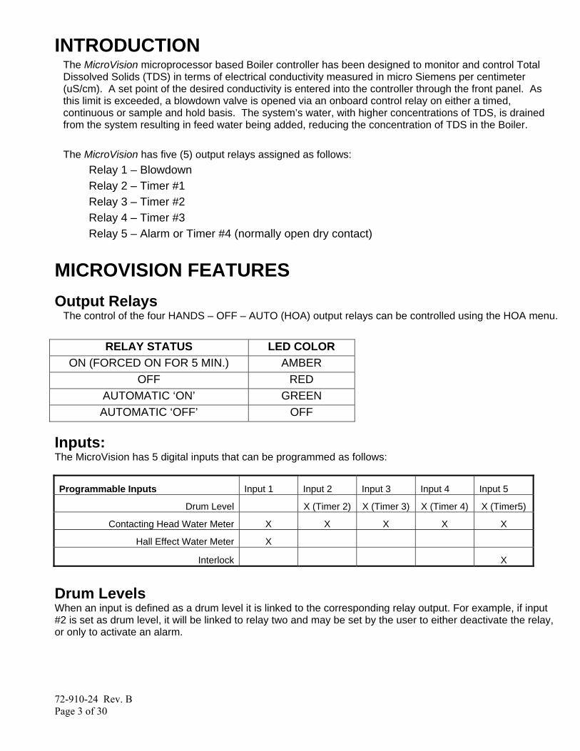
INTRODUCTION The MicroVision microprocessor based Boiler controller has been designed to monitor and control Total Dissolved Solids (TDS) in terms of electrical conductivity measured in micro Siemens per centimeter (uS/cm). A set point of the desired conductivity is entered into the controller through the front panel. As this limit is exceeded, a blowdown valve is opened via an onboard control relay on either a timed, continuous or sample and hold basis. The system’s water, with higher concentrations of TDS, is drained from the system resulting in feed water being added, reducing the concentration of TDS in the Boiler. The MicroVision has five (5) output relays assigned as follows:
Relay 1 – Blowdown Relay 2 – Timer #1 Relay 3 – Timer #2 Relay 4 – Timer #3 Relay 5 – Alarm or Timer #4 (normally open dry contact)
MICROVISION FEATURES
Output Relays The control of the four HANDS – OFF – AUTO (HOA) output relays can be controlled using the HOA menu.
RELAY STATUS LED COLOR ON (FORCED ON FOR 5 MIN.) AMBER
OFF RED AUTOMATIC ‘ON’ GREEN AUTOMATIC ‘OFF’ OFF
Inputs: The MicroVision has 5 digital inputs that can be programmed as follows:
Programmable Inputs Input 1 Input 2 Input 3 Input 4 Input 5
Drum Level X (Timer 2) X (Timer 3) X (Timer 4) X (Timer5)
Contacting Head Water Meter X X X X X
Hall Effect Water Meter X
Interlock X
Drum Levels When an input is defined as a drum level it is linked to the corresponding relay output. For example, if input #2 is set as drum level, it will be linked to relay two and may be set by the user to either deactivate the relay, or only to activate an alarm.
72-910-24 Rev. B Page 4 of 30
Interlock MicroVision has a dry contact interlock option for input number 5 only that will de-activate all of the control output relays upon an interlock condition indication. The interlock input requires that an auxiliary relay (not supplied) is installed across the boiler operation controls to produce a dry contact closure when the boiler is off line. The contacts of the aux. relay must be connected to input #5 for the controller to provide an Alarm condition and deactivate the relay outputs when the boiler is offline. “Interlock on” will be displayed when the system is offline. This input is active open:
Open = not interlocked; closed = Interlock on.
If an interlock or other alarm condition exists, the four (4) LED’s will flash until the alarm condition is cleared.
Water Meter Each input may be programmed as water meter inputs that are capable of reading a dry contact water meter. Input number one can be set to read a Hall Effect type water meter. Through programming this input can be used to feed inhibitor as well as totalizing water consumption.
Alarm Relay (Relay #5) MicroVision has a dedicated dry contact relay that can be used to interface with process control equipment or visual indicators. This relay is un-powered and may also be programmed as a timer.
4-20mA Output Connect your 4-20mA equipment to J8 (Fig. 7) pins + and -. The 4-20mA output uses 24VDC as a supply voltage. See the “Conductivity Menu” section (Page 24) for setting up and calibrating the 4-20mA output. When in the timed sample, or the sample and hold modes the 4-20mA output will only update during the sample time and the hold times. During the interval times the output will remain at the last sample value.

72-910-24 Rev. B Page 5 of 30
INSTALLATION
Opening The Enclosure Loosen the two (2) thumb screws to open the front cover of the controller, then loosen the inside panel thumb screw and carefully swing the panel to the right (Fig. 2).

72-910-24 Rev. B Page 6 of 30
Location
Select a mounting location convenient to grounded electrical and plumbing connections. It is recommended that you mount the controller on a wall or other vertical surface with adequate lighting at a comfortable level. A mounting-hole template is supplied with your controller. Installation should comply with all national, state, and local codes.
AVOID LOCATIONS WHERE THE CONTROLLER WOULD BE SUBJECTED TO EXTREME COLD OR HEAT {LESS THAN 0°F (-17,8°C) OR GREATER THAN 150 °F (65°C)}, DIRECT SUNLIGHT, VIBRATION, VAPORS, LIQUID SPILLS, OR EMI (ELECTROMAGNET INTERFERENCE; E.G., STRONG RADIO TRANSMISSION AND ELECTRIC MOTORS.)
SAFETY PROTECTION PROVIDED BY THE EQUIPMENT MAY BE IMPARED IF THE EQUIPMENT IS USED IN A MANNER NOT SPECIFIED BY THE MANUFACTURER.
Fig. 3 Mount the controller using the four (4) holes provided (Fig. 3).
Mounting Hardware Typically, use ¼” (6mm) or equivalent.
72-910-24 Rev. B Page 7 of 30
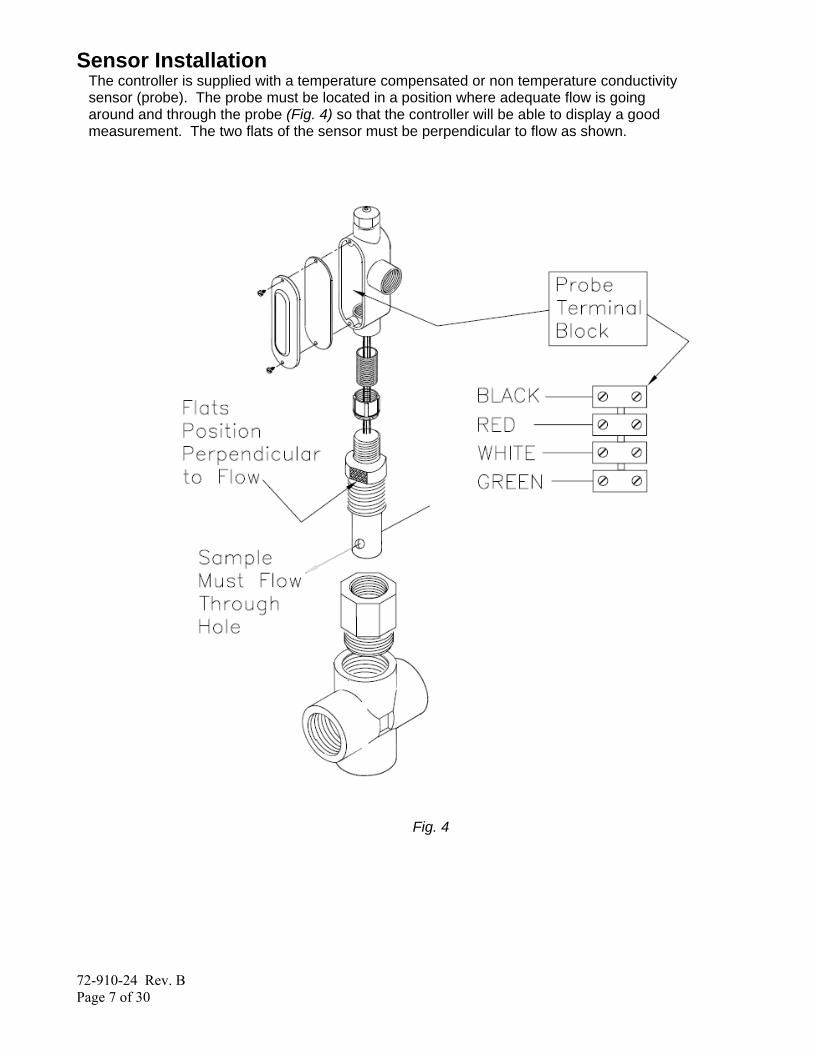
Sensor Installation The controller is supplied with a temperature compensated or non temperature conductivity sensor (probe). The probe must be located in a position where adequate flow is going around and through the probe (Fig. 4) so that the controller will be able to display a good measurement. The two flats of the sensor must be perpendicular to flow as shown.
Fig. 4
72-910-24 Rev. B Page 8 of 30
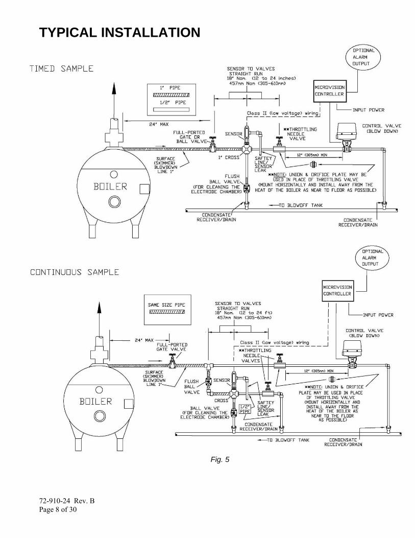
TYPICAL INSTALLATION
Fig. 5

72-910-24 Rev. B Page 9 of 30
IMPORTANT SYMBOL INFORMATION
Warning indicates a condition that could cause damage to both the equipment and
the personnel operating it. Pay close attention to any warning.
Primary Supply Ground must be connected to earth ground for safe operation of your controller.
Chassis Ground – Connect your equipment’s ground wire here for safe operation of your external devices.
ELECTRICAL WIRING
CONTROLLER MUST BE WIRED IN ACCORDANCE WITH ALL APPLICABLE ELECTRICAL CODES.
The MicroVision electronic input circuitry is fuse protected on both the hot and neutral inputs using a replaceable five amp fuse (Fig .6).
For additional protection of your instrument, use of a surge protector is recommended.
The controller should be connected to a dedicated power branch (i.e., its own wiring, circuit breaker, etc.). For best results, the ground should be independent (true earth) not shared.
A switch or circuit-breaker, marked as the unit’s disconnecting device should be included in the installation. It should be in close proximity to the unit and be easily reached by the operator
Pre-wired controllers are supplied with a 3-wire grounded power cord and 3-wire grounded receptacle cords for all controlled line voltage outputs.

72-910-24 Rev. B Page 10 of 30
RELAY BOARD CONNECTIONS
Fig. 6
Conduit Models (Wiring High Voltage) Conduit controllers have openings for conduit connections for hard wiring. (See Fig. 6) for input and output power connections. Use only 18 AWG (1,2 mm²) stranded wire for conduit power and load connections. Supply (input) A/C power is connected via the terminal block located on the back panel marked “A/C Power” (Fig. 6). The top part of this terminal block is removable to allow for easy access to the connector’s three (3) screws.
MAKE SURE THAT YOUR CONTROLLER VOLTAGE MATCHES THE INPUT VOLTAGE. DO NOT APPLY POWER UNTIL THIS CONDITION IS VERIFIED.
Make sure that all conduit connections are water tight.
The four (4) output relay terminal blocks are identified as: PL1 (bleed), PL2 (Inhib), PL3 (Bio A), and PL4 (Bio B). The Blowdown relay has a N.O. and a N.C. connection, the others are only N.O.
72-910-24 Rev. B Page 11 of 30
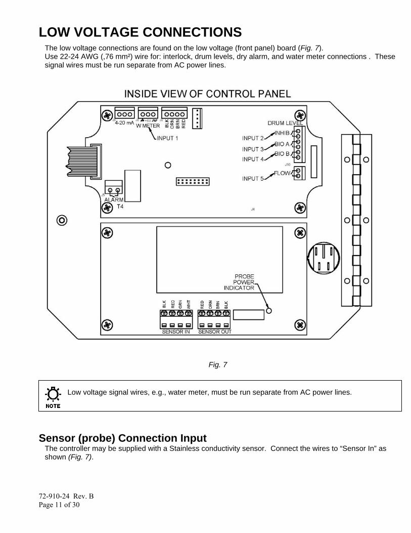
LOW VOLTAGE CONNECTIONS The low voltage connections are found on the low voltage (front panel) board (Fig. 7). Use 22-24 AWG (,76 mm²) wire for: interlock, drum levels, dry alarm, and water meter connections . These signal wires must be run separate from AC power lines.
Fig. 7
Low voltage signal wires, e.g., water meter, must be run separate from AC power lines.
Sensor (probe) Connection Input
The controller may be supplied with a Stainless conductivity sensor. Connect the wires to “Sensor In” as shown (Fig. 7).

72-910-24 Rev. B Page 12 of 30
Digital Inputs Input # 1 Connect your dry contact water meter to J3 of the top board. For proper connections, refer to (Fig. 7) for your meter type, Hall effect, or contacting head may be used. Input # 2 to # 4 Connect your water meter, or drum level switch to J10 (Fig. 7). They are labeled as, Input 2, 3, and 4. These are active closed: closed = low level; open = level is OK. Input # 5
Connect your water meter, drum level switch, or interlock auxiliary dry contact wires to J4 Interlock Input It is recommended that an auxiliary dry contact be used to make outputs inoperative when the boiler is shut down. Connect detection wires to J4 (Fig. 7), to use this interlock feature. This is active – open: open = not interlocked ; closed = Interlock On.
Alarm Relay Use J5 to connect your alarm reporting equipment. This relay will close when an alarm condition exists and will open when no alarm conditions are present. See the Trouble Shooting Guide (Page 31) for a description of alarm codes and their probable causes.
FRONT PANEL DESCRIPTION
Fig. 8
72-910-24 Rev. B Page 13 of 30
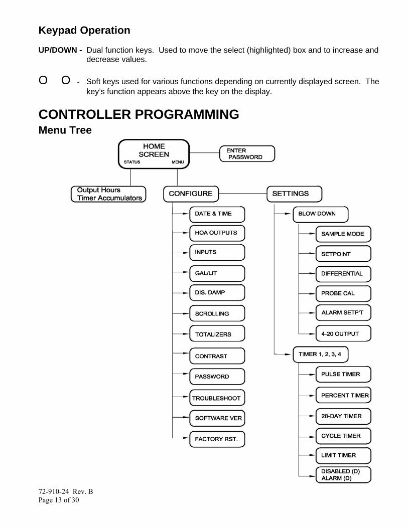
Keypad Operation UP/DOWN - Dual function keys. Used to move the select (highlighted) box and to increase and
decrease values. O O - Soft keys used for various functions depending on currently displayed screen. The
key’s function appears above the key on the display.
CONTROLLER PROGRAMMING Menu Tree

72-910-24 Rev. B Page 14 of 30
Menu Navigation MicroVision uses four front panel buttons to navigate through the different menus. Use these buttons to move up and down within a list of options or move right and left to enter or change parameter values. In some cases the Microvision display will prompt you to press the different buttons to assist you in selecting or changing data. Some menus may display highlighted menu options or a checkmark (√) next to a menu option. The highlighted menu option is used to indicate that another menu will be displayed if this option is chosen. The checkmark indicates that a particular control mode has been selected.
Home screen This screen is displayed during normal operation when there are no alarm conditions on the Microvision. If an alarm condition occurs an alarm message will flash on the screen. The four LED’s to the right of the display will also flash indicating an alarm has occurred. The MicroVision will return to this home screen if no buttons are pressed for five minutes after entering a menu. Main Menu The Main menu is the starting point for all subsequent menus.
Configure – This menu allows you to set the time and date, display contrast, water meter, etc. Settings – This menu allows you to set the conductivity, and chemical feed modes.
Status Screen
This screen shows the real-time data relating to the controller. This screen can be used to log the amount of time a particular output was energized since it was last reset. Below is a description of each of the data fields:
Home Screen Output hours Bdn: 123.4 Tmr 1: 123.4 Tmr 2: 123.4 Tmr 3: 123.4 Tmr 4 : 0.2 Last Error: Cond Low
Back | Reset
Home Screen Configure Settings Back | Select
Date/Time HOA Outputs Inputs Back | Select
√Auto On 5 Min Off Back | Select
01/23/09 | 11:42a Bd: Timed 2900 uS/cm Status | Menu

72-910-24 Rev. B Page 15 of 30
Bdn– The amount of time, in hours, the blowdown output was energized since it was last reset. Tmr 1 – The amount of time, in hours, the timer 1 output was energized since it was last reset. Tmr 2 – The amount of time, in hours, the timer 2 output was energized since it was last reset. Tmr 3 – The amount of time, in hours, the timer 3 output was energized since it was last reset. Tmr 4– The amount of time, in hours, the alarm output (or timer 4 if programmed) output was energized since it was last reset. Last Error – Shows the most recent error that was displayed on the controller. Pressing the reset key will cause the hour timers to reset to zero.
Configure Menu From the Configure menu you can select many different system configuration options.
Date/Time – Set the current date, date format, time, and time format. Date/Time – Set the current date, date format, time, and time format. HOA Outputs – Manually control the five relays. Inputs – Set the input type, drum level, or water meter type and volume. Gal/Lit – Set the display in Gallons or liters. Scrolling – Set the time between each timer’s status scrolling speed on the home screen. Totalizers- View the water meter totalizer values since the last user reset. Contrast – Set the display contrast. Password – Set the user password. Troubleshoot – View the signal inputs in real-time to diagnose wiring problems. Display Dampener – Set the display and control update period. Software Version – Displays the current software version. Factory Restore – Restore the parameters to factory default.
Date/Time Menu From the Date/Time menu you can set the data and time as well as the date and time display formats.
Set Date – Set the current date. Set Time – Set the current time. Date Format – Pick the day/month/year format. Time Format – Pick the 12-hour or 24-hour time of day format.
Home Screen
Configure
Date/Time
Set Date Set Time Date Format Time Format Back | Select
Home Screen Date/Time HOA Outputs Inputs Gal/Lit Scrolling Totalizers Contrast Password Troubleshoot Disp Damp Software Ver Factory Rst Back | Select
Configure

72-910-24 Rev. B Page 16 of 30
HOA Outputs Menu From the HOA Outputs menu you can manually set the five relay outputs. This is useful for servicing chemical pumps or troubleshooting electrical problems. You must first select the relay output to be controlled then select the relay state.
Blowdown – Force the blowdown control output on or off. Timer 1 – Force the Timer 1 control output on or off. Timer 2 – Force the Timer 2 control output on or off. Timer 3 – Force the Timer 3 control output on or off. Timer 4 – Force the Timer 4 control output on or off. Auto – Return the control output to normal operation. On 5 Min – Energize the control output for five minutes. Off – De-energize the control output indefinitely.
Forcing the output to Auto may cause the control output to energize without warning.
Inputs Menu From the Inputs menu you select what type of device the controller is attached to. Once the type of input has been entered the next screen will ask you for the gallons/liters per pulse or “K-factor”, or level action depending on the type of device.
Input Type – Select between a dry contact or Hall-effect water meter on input 1. Select between a dry contact water meter, or drum levels on input 2 to 4. Select between a dry contact water meter, or drum level or flow switch on input 5. Once the type is selected as a water meter the resolution or volume per pulse is then set.
Home Screen
Configure
Inputs
Input 1 Input 2 Input 3 Input 4 Input 5 Back | Select
Input 1
Dry Contact Hall Effect Drum low Back | Select
Input 2 -4Dry Contact Drum low Back | Select
Input 5
Home Screen
HOA Outputs
Blowdown Timer 1 Timer 2 Timer 3 Timer 4 Back | Select
Auto On 5 Min Off Back | Select
Dry Contact Flow Switch Drum low

72-910-24 Rev. B Page 17 of 30
Drum Levels Sub Menu From the Drum Level menu you select how you want the chemical pump control output to respond to a low drum level indication. Your choices are to allow the pump to continue to run or have the pump stop when its drum level goes low. Input one is tied to relay one
Pump Stops – Selecting this mode causes the timer outputs to de-energize when their drum level goes low. Pump Runs – Selecting this mode causes the timer outputs to remain energized even though their drum level has gone low.
When a drum level goes low the controller will go into alarm regardless of this setting. Re-filling a low drum may cause the pump control output to energize without warning.
Gallons or Liters
Gal/lit – Set how the controller should display the water meter units of measure.
Scrolling From the Display Scrolling setting you can adjust how frequently the controllers display will scroll from one timer’s status to the blowdown timers and conductivity readings on the home screen.
Scrolling – Set the number of seconds to scroll.
Home Screen
Configure
Scrolling
Scrolling 03 Sec Cancel |Enter
Home Screen
Configure
Gal/Lit
√Gallons Liters Cancel |Enter
Home Screen
Configure
Inputs
Dry Contact √Drum low Back | Select
Pump Stops √Pump Runs Back | Select
Input 2
72-910-24 Rev. B Page 18 of 30
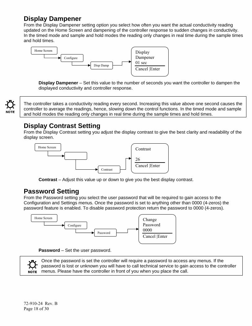
Display Dampener From the Display Dampener setting option you select how often you want the actual conductivity reading updated on the Home Screen and dampening of the controller response to sudden changes in conductivity. In the timed mode and sample and hold modes the reading only changes in real time during the sample times and hold times.
Display Dampener – Set this value to the number of seconds you want the controller to dampen the displayed conductivity and controller response.
The controller takes a conductivity reading every second. Increasing this value above one second causes the controller to average the readings, hence, slowing down the control functions. In the timed mode and sample and hold modes the reading only changes in real time during the sample times and hold times.
Display Contrast Setting From the Display Contrast setting you adjust the display contrast to give the best clarity and readability of the display screen.
Contrast – Adjust this value up or down to give you the best display contrast.
Password Setting From the Password setting you select the user password that will be required to gain access to the Configuration and Settings menus. Once the password is set to anything other than 0000 (4-zeros) the password feature is enabled. To disable password protection return the password to 0000 (4-zeros).
Password – Set the user password.
Once the password is set the controller will require a password to access any menus. If the password is lost or unknown you will have to call technical service to gain access to the controller menus. Please have the controller in front of you when you place the call.
Home Screen
Configure
Disp Damp
Display Dampener 01 sec Cancel |Enter
Home Screen
Configure
Password
Change Password 0000 Cancel |Enter
Contrast
Contrast 26 Cancel |Enter
Home Screen

72-910-24 Rev. B Page 19 of 30
Troubleshoot Screen From the Troubleshoot Screen you can view the MicroVision control inputs in real-time. This is a great tool for checking the correct operation of sensors that are attached to the controller.
Input 1 to 5– (J4 pins 1-2). Indicates current state closed, or open. Wk – Revolving week number between one and four. This is used in the 28 day timer Days/Weeks settings. Cnd – Displays the current conductivity reading in real time Tmp – Displays the current temperature in degrees C Day – Day of week. This is used in the 28 day timer Days/Weeks settings. Sec - Current clock seconds.
While this screen is displaying information the controller is still functioning normally and relay outputs may energize without warning due to changing signal inputs.
Software Version From the Software Version screen you can view the current software that is running in the Microvision controller.
Software Version – This screen displays the current software version.
Factory Reset Function From the Factory Reset Function screen you can force the controller to reset all of its internal parameter to the factory default values.
Use this function to reset the controller back to the factory defaults.
Be absolutely certain you want to reset all the parameters back to the factory defaults. Once the reset takes place there is no way to retrieve the previous parameters.
Home Screen
Configure
Troubleshoot
Ip 1: Open Ip 2: Open Ip 3: Open Ip 4: Open Ip 5: Open Cnd: 03500 Tmp: 65.3 C Wk: 2 Day:Mon Sec:23
Back | Back
Home Screen
Configure
Factory Rst
Factory Reset Are you sure! Cancel | OK
To RESET Enter 9999 0000 Cancel | OK
Home Screen
Configure
Software Ver
Software Version 01.00 Back |Back
72-910-24 Rev. B Page 20 of 30
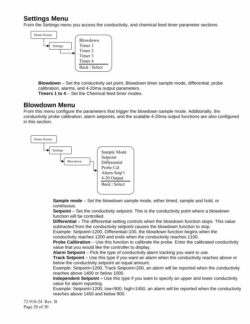
Settings Menu From the Settings menu you access the conductivity, and chemical feed timer parameter sections.
Blowdown – Set the conductivity set point, Blowdown timer sample mode, differential, probe calibration, alarms, and 4-20ma output parameters. Timers 1 to 4 – Set the Chemical feed timer modes.
Blowdown Menu From this menu configure the parameters that trigger the blowdown sample mode. Additionally, the conductivity probe calibration, alarm setpoints, and the scalable 4-20ma output functions are also configured in this section.
Sample mode – Set the blowdown sample mode, either timed, sample and hold, or continuous. Setpoint – Set the conductivity setpoint. This is the conductivity point where a blowdown function will be controlled. Differential – The differential setting controls when the blowdown function stops. This value subtracted from the conductivity setpoint causes the blowdown function to stop. Example: Setpoint=1200, Differential=100, the blowdown function begins when the conductivity reaches 1200 and ends when the conductivity reaches 1100. Probe Calibration – Use this function to calibrate the probe. Enter the calibrated conductivity value that you would like the controller to display. Alarm Setpoint – Pick the type of conductivity alarm tracking you want to use. Track Setpoint – Use this type if you want an alarm when the conductivity reaches above or below the conductivity setpoint an equal amount. Example: Setpoint=1200, Track Setpoint=200, an alarm will be reported when the conductivity reaches above 1400 or below 1000. Independent Setpoint – Use this type if you want to specify an upper and lower conductivity value for alarm reporting. Example: Setpoint=1200, low=900, high=1450, an alarm will be reported when the conductivity reaches above 1450 and below 900.
Home Screen
Settings
Blowdown
Sample Mode Setpoint Differential Probe Cal Alarm Setp’t 4-20 Output Back | Select
Home Screen
Blowdown Timer 1 Timer 2 Timer 3 Timer 4 Back | Select
Settings

72-910-24 Rev. B Page 21 of 30
4-20 Output – Use this option to configure how you want the 4-20ma output to behave with respect to the conductivity reading. Adjust Range – Use this option to set the low and hi conductivity readings used to scale the 4-20ma output. Example: Low Range=500, High Range=2000, when the conductivity reading is 500 the 4-20 ma output would be 4ma, when the conductivity reading is 2000 the 4-20ma output would be 20ma. Calibrate Output – Use this option to calibrate or “fine-tune” the 4-20ma output. Both the 4ma and 20ma settings can be adjusted a small amount to compensate for un-calibrated downstream meters or displays.
Blowdown Sample Modes Timed In the timed sample mode the controller will take a sample based on a user defined Interval Time and Sample Time. The Interval is the time in between the samples, the sample time is the duration of the sample. When the interval time expires, the sample time begins. If the conductivity is above the set point at the end of the sample time the blowdown valve will remain open until the conductivity is below the set point minus the differential. During the sample time the actual real time conductivity is displayed, during the interval time the last sample is frozen on the screen unless the blowdown relay is activated by the HOA function. The limit timer can be set to cause the controller to alarm if a blowdown cycle exceeds the time set by the user. The limit timer will not deactivate the blowdown valve; it will only provide and alarm indication. Continuous In the continuous mode the controller will take a sample continuously If the conductivity exceeds the set point the blowdown valve will open until the conductivity is below the set point minus the differential. The limit timer can be set to cause the controller to alarm if a blowdown cycle exceeds the time set by the user. The limit timer will not deactivate the blowdown valve; it will only provide and alarm indication. Sample and Hold In the sample and hold mode the controller will take a sample based on a user defined Interval Time and Sample Time. The Interval is the time in between the samples, the sample time is the duration of the sample. When the interval time expires, the sample time begins. At the end of the sample time, the blowdown valve is closed for the Hold time. When the hold time expires the controller will enter the interval time if the conductivity is not over the set point. If the conductivity is above the set point at the end of the Hold time the blowdown valve will open for the blowdown time and then close the valve for the hold time this cycle will repeat until the conductivity is below the set point minus the differential at the end of the hold time. During the sample time and hold times the actual real time conductivity is displayed, during the interval time the last sample is frozen on the screen unless the blowdown relay is activated by the HOA function.
Probe Calibration There are two methods of probe calibration that can be used to calibrate this probe depending on the blowdown sample mode selected. Calibration should be performed at the conductivity control set point, manually bring the boiler into control with a hand held tester before calibrating. This can be done with either the manual activation of the skimmer line blowdown, or by the bottom blowdown if possible. If the controller is calibrated at a point more than 1000uS/cm from the control set point it should be recalibrated after the boiler conductivity is in control.
72-910-24 Rev. B Page 22 of 30
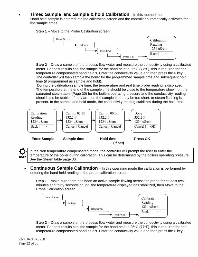
• Timed Sample and Sample & hold Calibration – In this method the Hand held sample is entered into the calibration screen and the controller automatically activates for the sample times.
Step 1 – Move to the Probe Calibration screen.
Step 2 – Draw a sample of the process flow water and measure the conductivity using a calibrated meter. For best results cool the sample for the hand held to 25°C (77°F), this is required for non-temperature compensated hand held’s. Enter the conductivity value and then press the > key. The controller will then sample the boiler for the programmed sample time and subsequent hold time (if programmed as sample and hold). During the calibration sample time, the temperature and real time probe reading is displayed. The temperature at the end of the sample time should be close to the temperature shown on the saturated steam table (Page 30) for the boilers operating pressure and the conductivity reading should also be stable. If they are not, the sample time may be too short, or steam flashing is present. In the sample and hold mode, the conductivity reading stabilizes during the hold time.
Enter Sample Sample time Hold time Press OK (If set)
In the Non temperature compensated mode, the controller will prompt the user to enter the temperature of the boiler during calibration. This can be determined by the boilers operating pressure. See the Steam table page 30.
• Continuous Sample Calibration – In this operating mode the calibration is performed by
entering the hand held reading in the probe calibration screen.
Step 1 – make sure there has been an active sample flowing across the probe for at least two minutes and thirty seconds or until the temperature displayed has stabilized, then Move to the Probe Calibration screen.
Step 2 – Draw a sample of the process flow water and measure the conductivity using a calibrated meter. For best results cool the sample for the hand held to 25°C (77°F), this is required for non-temperature compensated hand held’s. Enter the conductivity value and then press the > key.
Home Screen
Settings
Blowdown
Calibrate Reading 1234 uS/cm Back | >
Probe Cal
Home Screen
Settings
Blowdown
Calibration Reading 1234 uS/cm Back | >
Probe Cal
Calibration Reading 1234 uS/cm Back | >
Cal. In. 02:30 332.2 F 1234 uS/cm Cancel | Cancel
Cal. In. 00:00 332.2 F 1234 uS/cm Cancel | Cancel
Done 332.2 F 1234 uS/cm Cancel | OK

72-910-24 Rev. B Page 23 of 30
Timer Mode Menus From this menu pick the mode that the inhibitor feed will follow.
Limit Timer – Set this value to the maximum amount of time you want the inhibitor to feed while the blowdown function is running. If this time is exceeded the controller will go into alarm and the inhibitor feed control output will de-energize. Pulse Timer – See the menu for this function in the following section. Percent Timer – Set the timer run time period and percentage of the time period. Example: Cycle Time=60minutes, % Minutes to run=10, the timer will run for 10% of 60 minutes, or 6 minutes every 60 minutes. 28 Day Timer (Biocide) – See the menu for this function in the following section. Cycle Timer - See the menu for this function in the following section. Disabled – Deactivates the timer Alarm – Timer 4 only, the relay will activate for any system alarm.
Timer Modes - Limit From this menu configure how you want the inhibitor to feed while in Limit Timer mode.
Limit Timer – Set this value to the maximum amount of time you want the inhibitor to feed while the blowdown function is running. If this time is exceeded the controller will go into alarm and the inhibitor feed control output will de-energize.
Timer Modes – Pulse Timer Menu From this menu configure how you want the inhibitor to feed while in pulse timer mode. This mode uses the water meter input to cause a counter to accumulate a certain volume of water before the inhibitor is feed. Once the accumulated volume is reached the inhibitor is feed for the programmed Feed Time.
Home Screen
Settings
Timer 1
Pulse Timer √Limit Timer Perct Timer 28 Day Tmr Cycle Timer Disabled Back | Select
√LimitTimer
Home Screen
Settings
Timer 1
Limit Pulse Timer Percent Timer 28 Day Tmr Cycle Timer Disabled Back | Select
Home Screen
Settings
Timer 1
Feed Time Accum Set Accum Count Water Meter Back | Select √Pulse Timer
72-910-24 Rev. B Page 24 of 30
Feed Time – Set this value to the amount of time you want the timer to run for when the water meter accumulator reaches its target. Accumulator Set – Set this value to the amount of water that needs to accumulate prior to a timer run time. The units will be in gallons or liters depending on what you set the water meter units to. Accumulator Count – This is the current running count of the water meter accumulator. Water meter – Select which of the five possible water meter inputs will activate the pulse timer.
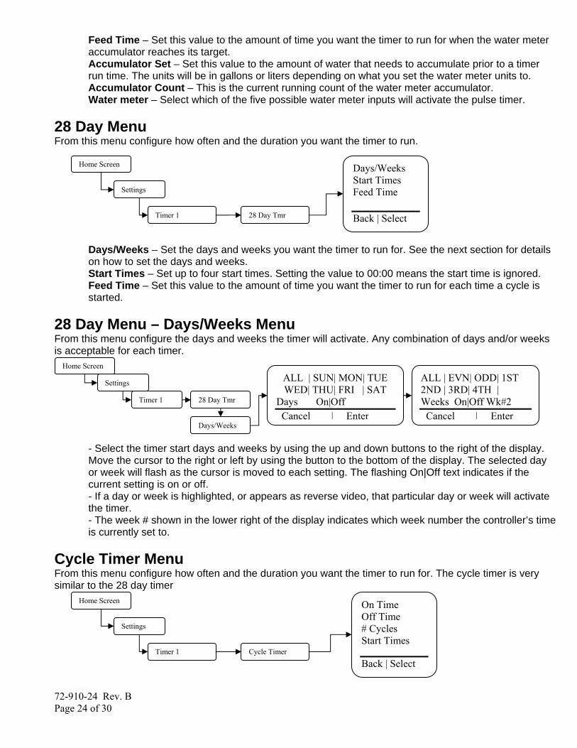
28 Day Menu From this menu configure how often and the duration you want the timer to run.
Days/Weeks – Set the days and weeks you want the timer to run for. See the next section for details on how to set the days and weeks. Start Times – Set up to four start times. Setting the value to 00:00 means the start time is ignored. Feed Time – Set this value to the amount of time you want the timer to run for each time a cycle is started.
28 Day Menu – Days/Weeks Menu From this menu configure the days and weeks the timer will activate. Any combination of days and/or weeks is acceptable for each timer.
- Select the timer start days and weeks by using the up and down buttons to the right of the display. Move the cursor to the right or left by using the button to the bottom of the display. The selected day or week will flash as the cursor is moved to each setting. The flashing On|Off text indicates if the current setting is on or off. - If a day or week is highlighted, or appears as reverse video, that particular day or week will activate the timer. - The week # shown in the lower right of the display indicates which week number the controller’s time is currently set to.
Cycle Timer Menu From this menu configure how often and the duration you want the timer to run for. The cycle timer is very similar to the 28 day timer
Home Screen
Settings
Timer 1
On Time Off Time # Cycles Start Times
Back | Select Cycle Timer
Home Screen
Settings
Timer 1
ALL | SUN| MON| TUE WED| THU| FRI | SAT
Days On|Off Cancel | Enter
Days/Weeks
ALL | EVN| ODD| 1ST 2ND | 3RD| 4TH | Weeks On|Off Wk#2 Cancel | Enter
28 Day Tmr
Home Screen
Settings
Timer 1
Days/Weeks Start Times Feed Time Back | Select 28 Day Tmr
72-910-24 Rev. B Page 25 of 30
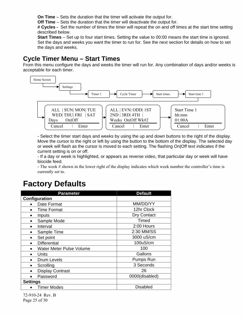
On Time – Sets the duration that the timer will activate the output for. Off Time – Sets the duration that the timer will deactivate the output for. # Cycles - Set the number of times the timer will repeat the on and off times at the start time setting described below. Start Times – Set up to four start times. Setting the value to 00:00 means the start time is ignored. Set the days and weeks you want the timer to run for. See the next section for details on how to set the days and weeks.
Cycle Timer Menu – Start Times From this menu configure the days and weeks the timer will run for. Any combination of days and/or weeks is acceptable for each timer.
- Select the timer start days and weeks by using the up and down buttons to the right of the display. Move the cursor to the right or left by using the button to the bottom of the display. The selected day or week will flash as the cursor is moved to each setting. The flashing On|Off text indicates if the current setting is on or off. - If a day or week is highlighted, or appears as reverse video, that particular day or week will have biocide feed. - The week # shown in the lower right of the display indicates which week number the controller’s time is currently set to.
Factory Defaults Parameter Default
Configuration • Date Format MM/DD/YY • Time Format 12hr Clock • Inputs Dry Contact • Sample Mode Timed • Interval 2:00 Hours • Sample Time 2:30 MM/SS • Set point 3000 uS/cm • Differential 100uS/cm • Water Meter Pulse Volume 100 • Units Gallons • Drum Levels Pumps Run • Scrolling 3 Seconds • Display Contrast 26 • Password 0000(disabled)
Settings • Timer Modes Disabled
Home Screen
Settings
Timer 1
ALL | SUN| MON| TUE WED| THU| FRI | SAT
Days On|Off Cancel | Enter
Start times
ALL | EVN| ODD| 1ST 2ND | 3RD| 4TH | Weeks On|Off Wk#2 Cancel | Enter
Cycle Timer
Start Time 1 hh:mm 01:00A Cancel | Enter
Start time 1
72-910-24 Rev. B Page 26 of 30
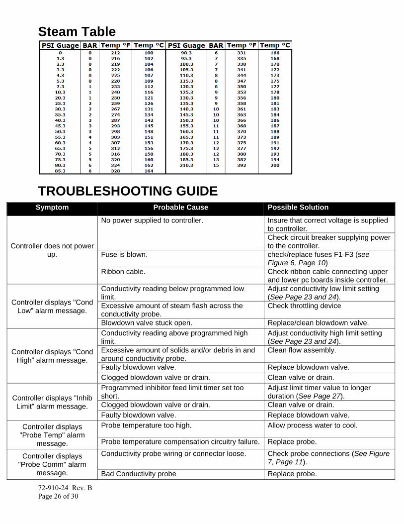
Steam Table
TROUBLESHOOTING GUIDE Symptom Probable Cause Possible Solution
Controller does not power up.
No power supplied to controller. Insure that correct voltage is supplied to controller. Check circuit breaker supplying power to the controller.
Fuse is blown. check/replace fuses F1-F3 (see Figure 6, Page 10)
Ribbon cable. Check ribbon cable connecting upper and lower pc boards inside controller.
Controller displays "Cond Low” alarm message.
Conductivity reading below programmed low limit.
Adjust conductivity low limit setting (See Page 23 and 24).
Excessive amount of steam flash across the conductivity probe.
Check throttling device
Blowdown valve stuck open. Replace/clean blowdown valve.
Controller displays "Cond High” alarm message.
Conductivity reading above programmed high limit.
Adjust conductivity high limit setting (See Page 23 and 24).
Excessive amount of solids and/or debris in and around conductivity probe.
Clean flow assembly.
Faulty blowdown valve. Replace blowdown valve. Clogged blowdown valve or drain. Clean valve or drain.
Controller displays "Inhib Limit" alarm message.
Programmed inhibitor feed limit timer set too short.
Adjust limit timer value to longer duration (See Page 27).
Clogged blowdown valve or drain. Clean valve or drain. Faulty blowdown valve. Replace blowdown valve.
Controller displays "Probe Temp" alarm
message.
Probe temperature too high. Allow process water to cool.
Probe temperature compensation circuitry failure. Replace probe.
Controller displays "Probe Comm" alarm
message.
Conductivity probe wiring or connector loose. Check probe connections (See Figure 7, Page 11).
Bad Conductivity probe Replace probe.
72-910-24 Rev. B Page 27 of 30
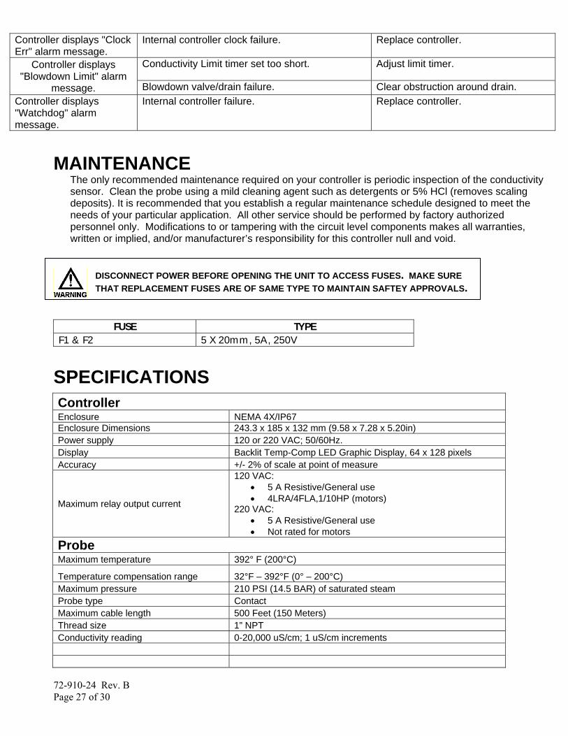
Controller displays "Clock Err" alarm message.
Internal controller clock failure. Replace controller.
Controller displays "Blowdown Limit" alarm
message.
Conductivity Limit timer set too short. Adjust limit timer.
Blowdown valve/drain failure. Clear obstruction around drain. Controller displays "Watchdog" alarm message.
Internal controller failure. Replace controller.
MAINTENANCE
The only recommended maintenance required on your controller is periodic inspection of the conductivity sensor. Clean the probe using a mild cleaning agent such as detergents or 5% HCl (removes scaling deposits). It is recommended that you establish a regular maintenance schedule designed to meet the needs of your particular application. All other service should be performed by factory authorized personnel only. Modifications to or tampering with the circuit level components makes all warranties, written or implied, and/or manufacturer’s responsibility for this controller null and void.
DISCONNECT POWER BEFORE OPENING THE UNIT TO ACCESS FUSES. MAKE SURE THAT REPLACEMENT FUSES ARE OF SAME TYPE TO MAINTAIN SAFTEY APPROVALS.
FUSE TYPE
F1 & F2 5 X 20mm, 5A, 250V
SPECIFICATIONS Controller Enclosure NEMA 4X/IP67 Enclosure Dimensions 243.3 x 185 x 132 mm (9.58 x 7.28 x 5.20in) Power supply 120 or 220 VAC; 50/60Hz. Display Backlit Temp-Comp LED Graphic Display, 64 x 128 pixels Accuracy +/- 2% of scale at point of measure
Maximum relay output current
120 VAC: • 5 A Resistive/General use • 4LRA/4FLA,1/10HP (motors)
220 VAC: • 5 A Resistive/General use • Not rated for motors
Probe Maximum temperature 392° F (200°C)
Temperature compensation range 32°F – 392°F (0° – 200°C) Maximum pressure 210 PSI (14.5 BAR) of saturated steam Probe type Contact Maximum cable length 500 Feet (150 Meters) Thread size 1” NPT Conductivity reading 0-20,000 uS/cm; 1 uS/cm increments
72-910-24 Rev. B Page 28 of 30
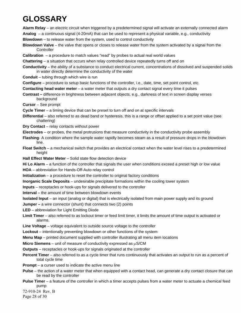
GLOSSARY Alarm Relay – an electric circuit when triggered by a predetermined signal will activate an externally connected alarm Analog – a continuous signal (4-20mA) that can be used to represent a physical variable, e.g., conductivity Blowdown – to release water from the system, used to control conductivity Blowdown Valve – the valve that opens or closes to release water from the system activated by a signal from the
Controller Calibration – a procedure to match values “read” by probes to actual real world values Chattering – a situation that occurs when relay controlled device repeatedly turns off and on Conductivity – the ability of a substance to conduct electrical current, concentrations of dissolved and suspended solids
in water directly determine the conductivity of the water Conduit – tubing through which wire is run Configure – procedure to setup basic functions of the controller, i.e., date, time, set point control, etc. Contacting head water meter – a water meter that outputs a dry contact signal every time it pulses Contrast – difference in brightness between adjacent objects, e.g., darkness of text in screen display verses
background Cursor – See prompt Cycle Timer – a timing device that can be preset to turn off and on at specific intervals Differential – also referred to as dead band or hysteresis, this is a range or offset applied to a set point value (see
chattering) Dry Contact – relay contacts without power Electrodes – or probes, the metal protrusions that measure conductivity in the conductivity probe assembly Flashing- A condition where the sample water rapidly becomes steam as a result of pressure drops in the blowdown
line. Float Switch – a mechanical switch that provides an electrical contact when the water level rises to a predetermined
height Hall Effect Water Meter – Solid state flow detection device Hi Lo Alarm – a function of the controller that signals the user when conditions exceed a preset high or low value HOA – abbreviation for Hands-Off-Auto relay control Initialization – a procedure to reset the controller to original factory conditions Inorganic Scale Deposits – undesirable precipitate formations within the cooling tower system Inputs – receptacles or hook-ups for signals delivered to the controller Interval – the amount of time between blowdown events Isolated Input – an input (analog or digital) that is electrically isolated from main power supply and its ground Jumper – a wire connector (shunt) that connects two (2) points LED – abbreviation for Light Emitting Diode Limit Timer – also referred to as lockout timer or feed limit timer, it limits the amount of time output is activated or
alarms. Line Voltage – voltage equivalent to outside source voltage to the controller Lockout – intentionally preventing blowdown or other functions of the system Menu Map – printed document supplied with controller illustrating all menu item locations Micro Siemens – unit of measure of conductivity expressed as μS/CM Outputs – receptacles or hook-ups for signals originated at the controller Percent Timer – also referred to as a cycle timer that runs continuously that activates an output to run as a percent of
total cycle time Prompt – a curser used to indicate the active menu line Pulse – the action of a water meter that when equipped with a contact head, can generate a dry contact closure that can
be read by the controller Pulse Timer – a feature of the controller in which a timer accepts pulses from a water meter to actuate a chemical feed
pump

72-910-24 Rev. B Page 29 of 30
Relay Indicators – lights (LED’s) located on the face of the control panel that indicate the status of individual relays Sample – to obtain a quantity of water for test purposes, Sample Line – a line through which a portion of the system water flows, where probes and other monitoring devices are
located controlled with isolation valves Sample Valve – small valve on the flow assembly that provides user a means to drain small quantities of water from the
system for testing Security Code – a code that can be entered by the user when configuring the system to secure access to the controller
settings Probe – a device connected to the controller which monitors or measures a characteristic value in the water, like the
conductivity Sensor – see Probe Set point – the user determined value within a monitored range at which the controller initiates action (e.g., activates a
relay) Set point Differential – also referred to as dead band or hysteresis; the offset applied to a set point to prevent
chattering of an output relay around a set point Soft Keys – Buttons on front panel used to input information Solenoid – an electromagnetically controlled switch System Overfeed – usually a malfunction condition where a feed pump fails in the Run (ON) condition System Parameters – see program parameters TDS – abbreviation for Total Dissolved Solids, measured in terms of electrical conductivity (μS/CM) Temperature Compensation – displays conductivity as if measured at 77°F (25°C) Toroidal Conductivity – Non-contacting conductivity sensor used for high values Totalizer – a re-settable function of the controller that keeps count of the number of water meter pulses μS/CM – conductivity unit of measure. Often referred to as micro Siemens Y-Strainer – inline filter or screen to remove debris from system flow assembly
Factory Service Policy Your MICROVISION is a state of the art microprocessor based controller. If you are experiencing a problem with your process control instrument, first consult the troubleshooting guide in this manual. If the problem is not covered or cannot be solved, contact Technical Services for assistance:
PULSAFEEDER INC. (SPO) 27101 AIRPORT ROAD PUNTA GORDA, FL 33982 941-575-3800
Trained technicians are available to diagnose your problem and arrange a solution. Solutions may include purchase of replacement parts or returning the controller to the factory for inspection and repair. All returns require a Return Authorization number to be issued by Pulsafeeder. Parts purchased to correct a warranty issue may be credited after an examination of original parts by Pulsafeeder. Warranty parts returned as defective which test good will be sent back freight collect. No credit will be issued on any replacement electronic parts. Any modifications or out-of-warranty repairs will be subject to bench fees and costs associated with replacement parts.
72-910-24 Rev. B Page 30 of 30
Warranty Pulsafeeder, Inc. warrants control systems of its manufacture to be free of defects in material or workmanship. Liability under this policy extends for 24 months from date of shipment. Electrodes/probes are considered maintenance items and as such are warranted for six (6) months from the date of shipment of the controller. Electrodes/probes purchased as spare parts are warranted for 24 months from date of shipment. The manufacturer's liability is limited to repair or replacement of any failed equipment or part, which is proven defective in material or workmanship upon completion of the manufacturer's examination. This warranty does not include removal or installation costs and in no event shall the manufacturer's liability exceed the selling price of such equipment or part. The manufacturer disclaims all liability for damage to its products through improper installation, maintenance, use, or attempts to operate such products beyond their functional capacity, intentionally or otherwise, or any unauthorized repair. The manufacturer is not responsible for consequential or other damages, injuries, or expense incurred through the use of its products. The above warranty is in lieu of any other warranty, whether expressed or implied. The manufacturer makes no warranty of fitness or merchantability. No agent of ours is authorized to provide any warranty other than the above.
EC Declaration of Conformity We, Pulsafeeder Inc., declare under sole responsibility that Microvision equipment to which this declaration relates is in sole conformity with relevant sections of the applicable EC standards and other normative documents listed on this document. If changes are made to the product which is covered by this declaration of conformity, the declaration of conformity is no longer valid. - Radiated emissions EN 61326 (EN 61326 Radiated Emissions) - Harmonic current emissions (EN 61000-3-2: 2000) - Voltage fluctuations and flicker (EN 61000: 2005) (EN 61000-3-3:95+A1:01 +A2:06) - Electrostatic Discharge Immunity Test (IEC 61000-4-2: 2001 Edition 1.4) (EN 61000-4-2:95 +1.98+A2:01) - Radiated immunity test (EN 61000-4-3:02 +A1:02) - Electrical Fast Transient/Burst Immunity Test (IEC 61000-4-4:02004) (EN 61000-4-4:2004) - Surge Immunity Test (IEC 61000-45: 2001) (EN 61000-4-5:95 +A1:01)) - Immunity to conducted disturbances (IEC 6100-4-6:2003 +A1:2004 +A2:2006) (EN 61000-4-6: 2007) - Power Frequency Magnetic Field Immunity Test (EN 61000-4-8:93)
- Voltage Dips,Short Interruptions and Voltage Variations Immunity Tests (IECC 61000-4-11: 2004) (EN61000-4- 11:2004)
- 2002/96/EG (WEEE) compliant - RoHS complient
USA Pulsafeeder, Inc. 27101 Airport Rd. Punta Gorda, FL 33982 USA (941) 575-3800 www.pulsa.com
European Union (EU) Knight UK Limited 15 Brunel Centre Newton Road Crawley, West Sussex RH10 9TU, UK