Microvascular decompression of cranial nerves: lessons learned...
8
ASCULAR arterial contacts with the dorsal root of the trigeminal nerve were first described in 1929 by Dandy. 5 Although he characterized these find- ings in subsequent communications, 4,6 it was not until the 1950s that Gardner and Miklos 8 and Taarnhøj 12 reported the beneficial effects of decompressing the trigeminal nerve for tic douloureux. Similar observations of vascu- lar compression of the seventh cranial nerve in patients with hemifacial spasm were first reported by Campbell and Keedy 3 in 1947 and by Laine and Nayrac 10 in 1948. Gardner and Sava 9 later extended these descriptions and proposed decompression of the facial nerve for hemifacial spasm in 1962. Despite these seminal observations, it took another 10 to 15 years before microvascular decompres- sion became an accepted treatment for cranial nerve syn- dromes. Early posterior fossa surgery was performed without the aid of magnification or adequate lighting and pro- duced high rates of morbidity and mortality. Initially, procedures were performed with the patient prone, with planned partial or complete nerve section. Over the years, the goals of the operation changed and technological ad- vances, combined with surgical innovations, helped to make this procedure safer and more effective. We review the senior author’s (P.J.J.) 29 years of experience in per- forming this operation, and we detail many of the techni- cal aspects that have contributed to minimize complica- tions. We propose a six-step method of performing micro- vascular decompression and describe six surgical “pearls” that make this operation safer and more effective. Impor- tant modifications of the initial procedure include patient positioning and the overall goal of surgery. The patient is now surgically treated while in the lateral or park-bench position, and the goal of the surgery is nerve decompres- sion rather than nerve section. Such modifications, in ad- dition to many others described herein, have greatly re- duced the attendant risks of operative morbidity and have improved outcome. Operative Technique Step 1. Positioning of the Patient “Vertex position dictates cranial nerve exposure” (P.J.J.). It has been said that the most important part of a surgi- cal procedure occurs before the skin incision, and much of the ease or difficulty of the microvascular decompression procedure is determined by patient positioning. The pa- tient is placed on the operating room table with the head at the foot of the bed to maximize the surgeon’s comfort J. Neurosurg. / Volume 90 / January, 1999 J Neurosurg 90:1–8, 1999 Microvascular decompression of cranial nerves: lessons learned after 4400 operations MARK R. MCLAUGHLIN, M.D., PETER J. JANNETTA, M.D., BRENT L. CLYDE, M.D., BRIAN R. SUBACH, M.D., CHRISTOPHER H. COMEY , M.D., AND DANIEL K. RESNICK, M.D. Department of Neurological Surgery, University of Pittsburgh Medical Center, Pittsburgh, Pennsylvania Object. Microvascular decompression has become an accepted surgical technique for the treatment of trigeminal neuralgia, hemifacial spasm, glossopharyngeal neuralgia, and other cranial nerve rhizopathies. The senior author (P.J.J.) began performing this procedure in 1969 and has performed more than 4400 operations. The purpose of this article is to review some of the nuances of the technical aspects of this procedure. Methods. A review of 4415 operations shows that numerous modifications to the technique of microvascular decompression have occurred during the last 29 years. Of the 2420 operations performed for trigeminal neuralgia, hemifacial spasm, and glossopharyngeal neuralgia before 1990, cerebellar injury occurred in 21 cases (0.87%), hearing loss in 48 (1.98%), and cerebrospinal fluid (CSF) leakage in 59 cases (2.44%). Of the 1995 operations per- formed since 1990, cerebellar injuries declined to nine cases (0.45%), hearing loss to 16 (0.8%), and CSF leakage to 37 (1.85% p , 0.01, test for equality of distributions). The authors describe slight variations made to maximize surgical exposure and minimize potential complications in each of the six principal steps of this operation. These modifications have led to decreasing complication rates in recent years. Conclusions. Using the techniques described in this report, microvascular decompression is an extremely safe and effective treatment for many cranial nerve rhizopathies. KEY WORDS • microvascular decompression • trigeminal neuralgia • hemifacial spasm • glossopharyngeal nerve V 1
Transcript of Microvascular decompression of cranial nerves: lessons learned...

ASCULAR arterial contacts with the dorsal root ofthe trigeminal nerve were first described in 1929by Dandy.5 Although he characterized these find-
ings in subsequent communications,4,6 it was not until the1950s that Gardner and Miklos8 and Taarnhøj12 reportedthe beneficial effects of decompressing the trigeminalnerve for tic douloureux. Similar observations of vascu-lar compression of the seventh cranial nerve in patientswith hemifacial spasm were first reported by Campbelland Keedy3 in 1947 and by Laine and Nayrac10 in 1948.Gardner and Sava9 later extended these descriptions andproposed decompression of the facial nerve for hemifacialspasm in 1962. Despite these seminal observations, it tookanother 10 to 15 years before microvascular decompres-sion became an accepted treatment for cranial nerve syn-dromes.
Early posterior fossa surgery was performed withoutthe aid of magnification or adequate lighting and pro-duced high rates of morbidity and mortality. Initially,procedures were performed with the patient prone, withplanned partial or complete nerve section. Over the years,the goals of the operation changed and technological ad-vances, combined with surgical innovations, helped tomake this procedure safer and more effective. We reviewthe senior author’s (P.J.J.) 29 years of experience in per-forming this operation, and we detail many of the techni-
cal aspects that have contributed to minimize complica-tions.
We propose a six-step method of performing micro-vascular decompression and describe six surgical “pearls”that make this operation safer and more effective. Impor-tant modifications of the initial procedure include patientpositioning and the overall goal of surgery. The patient isnow surgically treated while in the lateral or park-benchposition, and the goal of the surgery is nerve decompres-sion rather than nerve section. Such modifications, in ad-dition to many others described herein, have greatly re-duced the attendant risks of operative morbidity and haveimproved outcome.
Operative Technique
Step 1. Positioning of the Patient
“Vertex position dictates cranial nerve exposure”(P.J.J.).
It has been said that the most important part of a surgi-cal procedure occurs before the skin incision, and much ofthe ease or difficulty of the microvascular decompressionprocedure is determined by patient positioning. The pa-tient is placed on the operating room table with the headat the foot of the bed to maximize the surgeon’s comfort
J. Neurosurg. / Volume 90 / January, 1999
J Neurosurg 90:1–8, 1999
Microvascular decompression of cranial nerves: lessonslearned after 4400 operations
MARK R. MCLAUGHLIN, M.D., PETER J. JANNETTA, M.D., BRENT L. CLYDE, M.D.,BRIAN R. SUBACH, M.D., CHRISTOPHER H. COMEY, M.D., AND DANIEL K. RESNICK, M.D.
Department of Neurological Surgery, University of Pittsburgh Medical Center, Pittsburgh,Pennsylvania
Object. Microvascular decompression has become an accepted surgical technique for the treatment of trigeminalneuralgia, hemifacial spasm, glossopharyngeal neuralgia, and other cranial nerve rhizopathies. The senior author(P.J.J.) began performing this procedure in 1969 and has performed more than 4400 operations. The purpose of thisarticle is to review some of the nuances of the technical aspects of this procedure.
Methods. A review of 4415 operations shows that numerous modifications to the technique of microvasculardecompression have occurred during the last 29 years. Of the 2420 operations performed for trigeminal neuralgia,hemifacial spasm, and glossopharyngeal neuralgia before 1990, cerebellar injury occurred in 21 cases (0.87%),hearing loss in 48 (1.98%), and cerebrospinal fluid (CSF) leakage in 59 cases (2.44%). Of the 1995 operations per-formed since 1990, cerebellar injuries declined to nine cases (0.45%), hearing loss to 16 (0.8%), and CSF leakageto 37 (1.85% p , 0.01, test for equality of distributions). The authors describe slight variations made to maximizesurgical exposure and minimize potential complications in each of the six principal steps of this operation. Thesemodifications have led to decreasing complication rates in recent years.
Conclusions. Using the techniques described in this report, microvascular decompression is an extremely safeand effective treatment for many cranial nerve rhizopathies.
KEY WORDS • microvascular decompression • trigeminal neuralgia •hemifacial spasm • glossopharyngeal nerve
V
1

during the microsurgical portion of the procedure. Fol-lowing induction of anesthesia and intubation, a three-point head-fixation device is applied and the patient isplaced in the lateral decubitus position with appropriatepadding of pressure points and an axillary roll. The neckis flexed slightly with the chin approximately two fingerbreadths from the sternum (Fig. 1 upper). The head isrotated approximately 10˚ away from the affected side. Ifa trigeminal or cochlear approach is planned, the vertex iskept parallel to the floor to keep the seventh–eighth cra-nial nerve complex at a more inferior position in relationto the trigeminal nerve. If a facial nerve or lower brain-stem approach is planned, the vertex is dropped 15˚ to-ward the floor to expose the proximal aspect of the sev-enth nerve and rotate the vestibulocochlear complex morecephalad (Fig. 1 lower). The head holder is secured in theproper position. The patient is taped securely to the tableat the hips and chest to allow rotation of the table duringthe operation. Finally, the patient’s shoulder is taped downand placed out of the way.
Step 2. Surgical Incision
“The placement of the incision is variable depending onthe size and thickness of the patient’s neck” (P.J.J.).
A 3 3 3–cm area behind the ear is shaved and bonelandmarks are identified by palpation before the patient isprepared for surgery. The mastoid eminence, digastricgroove, and inion should be identified and an iniomeatalline drawn to define the transverse sinus. Laterally, overthe digastric groove a second line is drawn. The intersec-tion of these lines reveals the junction of the transverseand sigmoid sinuses. This allows the surgeon a “mind’seye” view of optimal burr hole placement. These externallandmarks guide the surgeon to minimize the length ofthe incision and to allow adequate exposure for burr holeplacement (Fig. 2 upper). A vertical incision is drawn 3 to5 cm long, approximately 0.5 cm posterior (medial) andparallel to the hair line. Identical incisions are used forboth upper and lower cranial nerve exposures. A slightlyshorter incision is required for thin- and long-necked pa-tients. For short- and thick-necked patients, the incisionshould be slightly longer with the inferior aspect angledmore posteriorly (medially). This angled incision requiresslightly more extensive muscle dissection over the mas-toid and digastric groove, but positions the thicker neckmusculature posteriorly (medially), allowing freer move-ment of the surgeon’s hands and instruments while per-forming the microsurgery (Fig. 2 lower). Three-quartersof the incision should be drawn inferior to the junction ofthe transverse and sigmoid sinuses and one-quarter shouldbe above. The area is prepared and draped in the usualfashion and the incision is made down to the occipitalbone by using monopolar cautery. The soft tissues aredissected using a periosteal elevator and electrocauterywhere necessary. The initial periosteal dissection shouldproceed anteriorly (laterally) before completing the poste-rior (medial) dissection. This provides better fixation withthe Weitlaner retractor. The anterior (lateral) and inferioraspects of the mastoid eminence must be cleared of softtissue. The nuchal muscles are dissected with electrocaut-ery and the transverse occipital artery is identified, ligat-ed, and divided. The mastoid emissary vein is usuallyidentified and must be waxed in its fossa. An angled Weit-laner cerebellar retractor is put in place. In thin-neckedpatients a straight Weitlaner retractor often gives adequateexposure and takes up less room within the incisionalopening.
Step 3. Bone Removal
“The junction of the transverse and sigmoid sinusesmust be visualized before the dural opening” (P.J.J.).
Before burr hole placement, bone landmarks should bewell exposed. The digastric groove should be clearly visu-alized and the soft tissue should be dissected slightly ante-rior to this landmark. Often the external aspect of theemissary vein does not lie directly over the sinus; rather,the vein meanders in a rostrolateral direction before enter-ing the proximal sigmoid sinus. Therefore, the mastoidemissary vein is a good landmark for the underlying junc-tion of the transverse and sigmoid sinuses. The asterionlocation is variable and, thus, is not a reliable landmark forthe sinus junction.7 The burr hole should be placed over
M. R. McLaughlin, et al.
2 J. Neurosurg. / Volume 90 / January, 1999
FIG. 1. Upper: Drawing showing the patient’s head placed atthe foot of the operating table to allow more leg room for the sur-geon during the microsurgical portion of the procedure. The headis secured with three-point fixation and the patient is turned in thelateral decubitus position. The head is rotated slightly away fromthe affected side and flexed to approximately two finger breadthsfrom the sternum. Lower: Drawings showing how the angle ofthe vertex is tailored depending on the cranial nerve approach. Fortrigeminal or cochlear nerve approaches, the vertex of the head iskept parallel to the floor to keep the seventh–eighth nerve complexat a more inferior position with respect to the trigeminal nerve. Fora seventh or lower cranial nerve approach, the vertex is dropped15˚ toward the floor to rotate and expose the proximal aspect of theseventh nerve and to rotate the vestibulocochlear complex morecephalad.
the mastoid emissary vein by using a perforator or high-speed drill. The goal of bone exposure should be to iden-tify the edge of the junction of the transverse and sigmoidsinuses first. A small craniectomy can then be tailored ac-cording to the cranial nerve approach desired (Fig. 3). Fora trigeminal or cochlear nerve approach, the craniectomyshould be shaped as an isosceles triangle with the apex atthe junction of the transverse and sigmoid sinuses. For afacial or lower cranial nerve approach, the apex of the tri-angle should be at the edge of the jugular bulb.
It is important to remove a portion of the posterior mas-toid air cells and to bevel the craniectomy outward so thatno bone overhang will limit the dural opening. Mastoid aircells should be thoroughly waxed. Either a curvilinear orT-shaped incision is made in the dura mater. This incisionmust expose the most superior and lateral corner of thedura adjacent to the junction of the transverse and sigmoid
sinuses to allow a direct corridor along the petro-tentorialbone. The bone work must be anterior (lateral) enough(usually into mastoid air cells) to allow dural incision andreflection.
Step 4. Turning the Corner
“Turning the corner is the most dangerous stage of theoperation and must be executed with patience and theutmost care” (P.J.J.).
After the dura is sutured back, an operative microscopewith a 250-mm objective lens is brought into the field.“Turning the corner” or exposing the cerebellopontineangle may be difficult and hazardous. The surgeon shouldallow some drainage of cerebrospinal fluid (CSF) beforeplacing the microretractor. Occasionally, gentle advance-ment of a cottonoid with a rubber dam is required to drainCSF from the cerebellopontine angle before placement ofa retractor. All cottonoids are moistened with saline andare paired with an appropriately sized (0.5 3 2–in) pieceof latex cut from a sterile glove. The latex prevents adhe-sion to the cerebellum and allows easy advancement ofcottonoids medially to the cerebellopontine angle. If thereis adequate CSF egress, a lumbar drain is not necessary.After the CSF has been drained, the cerebellum should be-gin to fall away from the petro-tentorial junction. A ta-pered retractor blade, bent proximally to a 60˚ angle, isplaced over the previously placed rubber dam/cottonoidcombination. The retractor should be no longer than nec-essary (approximately 6 in) because an overly prominentretractor can be bumped accidentally.
For trigeminal and cochlear nerve approaches, the bladeand cottonoid are placed over the superolateral aspect ofthe cerebellar surface and the ala of the cerebellum isgently elevated. The goal of retraction for all approachesin this region is always to elevate the cerebellum slightlytoward the surgeon and not simply to compress it medial-ly. This facilitates more CSF drainage, thereby minimiz-ing the need for cerebellar retraction. The petrosal veincomplex is identified and placed on gentle traction withthe retractor. Using microbipolar electrocautery, the veincomplex is coagulated and partially divided to verify ade-quate hemostasis. The complex is then coagulated a sec-
J. Neurosurg. / Volume 90 / January, 1999
Microvascular decompression complication avoidance
3
FIG. 2. Upper: Drawing depicting how the intersection of thedigastric groove and the iniomeatal line defines the junction of thetransverse and sigmoid sinuses. With a “mind’s eye” view of opti-mal burr hole placement and craniectomy, an incision is drawncentered over the planned craniectomy. Lower: Drawings show-ing different surgical incisions based on the size of the patient’sneck. Short and thick–necked patients require a more posteriorly(medially) directed incision. This angled incision positions thethicker neck musculature more posteriorly (medially) and out ofthe operative field. This small adjustment is critical in allowingfreer movement of the surgeon’s hands and instruments while per-forming the microsurgery.
FIG. 3. Drawing depicting how bone exposure should demon-strate the junction of the transverse and sigmoid sinuses. Surgicalexposure can then be tailored according to the cranial nerve ap-proach desired.
ond time and cut completely. On entering the cerebellopontine angle, the first struc-
ture visualized will be the seventh–eighth nerve complex,located superficially and caudal to the trigeminal nerve.The trigeminal nerve is located in the most superior anddeepest position. The petrosal vein complex usually con-sists of a confluence of two or three veins draining into thetentorial edge. If bleeding is encountered from this com-plex, it may be torrential. Occasionally, this can even oc-cur from gentle cerebellar retraction before division of thevein. Bleeding can be controlled by gentle pressure andpacking of the tentorial side by using Surgicel and a cot-tonoid. The retractor can be used to exert gentle pressurewhile the surgeon looks for the free end of the avulsedvein (Fig. 4). Once the avulsed vein is identified and coag-ulated, the procedure can continue. If bleeding is severe, alarge bore suction tip can be used to allow visualization ofthe field. Additionally, placing the patient in the reverseTrendelenburg position will decrease venous pressure andbleeding. In the senior author’s experience, bleeding canalways be controlled, but it may require tamponade for aslong as 10 to 30 minutes.
For seventh nerve or lower cranial nerve decompres-sions, an inferior approach is required. The retractor bladeis placed over the rubber dam and cottonoid on the infe-rolateral aspect of the cerebellum and the cerebellar ton-sils are gently elevated. The cisterna magna is identifiedand opened with a bent 25-gauge needle or microscissors.After adequate CSF drainage, the ninth, 10th, and 11thcranial nerves are identified as they enter the jugular fora-men. Slightly more superiorly, the seventh–eighth nervecomplex can be seen.
Step 5. Nerve Decompression
“The pathology lies at the brainstem side of the nerve,but may be more lateral” (P.J.J.).
Decompression is relatively straightforward if the sur-geon keeps two principles in mind at all times: 1) “theremust be a vessel, and it is my job to find it”; and 2) the
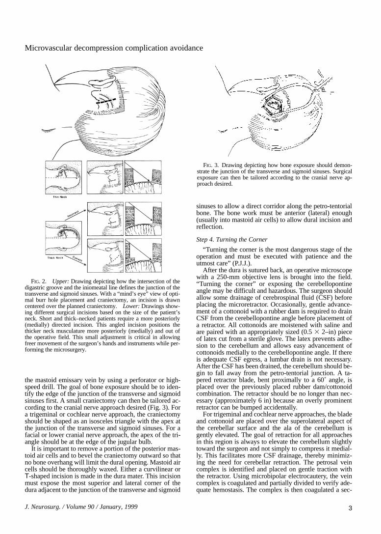
dorsal root entry or exit zone can be variable in length,particularly in the case of the trigeminal nerve, and mayextend to a more distal portion of the nerve. Therefore, thenerve should be inspected from its origin at the brainstemlaterally to its exit from the cerebellopontine angle and allvessels should be treated (Fig. 5).
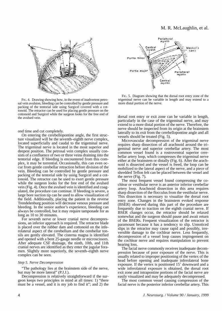
Microvascular decompression of the trigeminal nerverequires sharp dissection of all arachnoid around the tri-geminal nerve and superior cerebellar artery. The mostcommon vessel found is a rostroventral superior cere-bellar artery loop, which compresses the trigeminal nerveeither at the brainstem or distally (Fig. 6). After the arach-noid is dissected and the vessel is freed, the loop can bemobilized to the lateral aspect of the nerve, and a piece ofshredded Teflon felt can be placed between the vessel andthe nerve (Fig. 7).
The most frequent vessel found compressing the co-chlear or vestibular nerve is an anterior inferior cerebellarartery loop. Arachnoid dissection in this area requiressharp dissection of the flocculus from the vestibular nerve.This dissection is necessary to visualize the dorsal rootentry zone. Changes in the brainstem evoked response(BSER) observed during this part of the procedure arefrequently due to traction on the eighth cranial nerve. IfBSER changes occur, the retractor should be relaxedsomewhat and the surgeon should pause and await returnof the BSERs. Frequent visualization of the retractor isparamount because it has a tendency to slip. Unnoticedslips in the retractor may cause rapid and possibly, irre-versible damage to the cochlear nerve. Less frequently,decompression of a vessel loop causes impingement onthe cochlear nerve and requires manipulation to preventhearing loss.
The facial nerve commonly receives inadequate decom-pression because of poor exposure of the nerve. This isusually related to improper positioning of the vertex of thehead before opening and inadequate inferolateral boneexposure. If the vertex is positioned 15˚ downward and awide inferolateral exposure is obtained, the dorsal rootexit zone and intrapontine portions of the facial nerve areeasily visualized and may be adequately decompressed.
The most common vessel causing compression of thefacial nerve is the posterior inferior cerebellar artery. This
M. R. McLaughlin, et al.
4 J. Neurosurg. / Volume 90 / January, 1999
FIG. 4. Drawing showing how, in the event of inadvertent petro-sal vein avulsion, bleeding can be controlled by gentle pressure andpacking of the tentorial side using Surgicel covered with a cot-tonoid. The retractor can be used for placing gentle pressure on thecottonoid and Surgicel while the surgeon looks for the free end ofthe avulsed vein.
FIG. 5. Diagram showing that the dorsal root entry zone of thetrigeminal nerve can be variable in length and may extend to amore distal portion of the nerve.
vessel must be sharply dissected free from the arachnoidand mobilized laterally away from the nerve so that aTeflon implant can be placed. In cases of atypical hemifa-cial spasm, the pathological vascular entity is almost al-ways located rostral to the nerve or between the seventhand eighth nerves. An anterior inferior cerebellar arteryrunning between the seventh and eighth nerve may have aperforating branch to the pons that must be preserved.
Exposure of the lower cranial nerves and lateral medul-la oblongata is excellent with inferolateral placement ofthe retractor. The arachnoid is dissected sharply and thepathological vascular entity can be identified and treatedappropriately.
Step 6. Surgical Closure
“Wax the bone edges on the way in and on the way out”(P.J.J.).
At the conclusion of the decompression procedure, sev-eral Valsalva maneuvers are performed to ensure hemo-stasis. The retractor is then removed and the cerebellarsurface is carefully inspected. Valsalva maneuvers are re-peated to verify hemostasis. The area is gently irrigatedwith warm saline bulb irrigation and the durotomy isclosed. Syringe irrigation is to be avoided because it mayinjure the cochlear nerve with a jet of fluid. We are aggres-sive in performing dural closure in which fascia/musclegrafts from the inferior portion of the incision are used asnecessary to ensure watertight closure. The bone edges ofthe mastoid air cells are thoroughly waxed for a secondtime. A small pad of cellulose and Gelfoam are thenplaced over the durotomy, and cranioplasty is performedusing methylmethacrylate or wire mesh. The deep andsuperficial muscles are approximated with interrupted No.2.0 absorbable sutures, and the fascia is closed with thesame type of sutures. The fascial closure must be water-tight to prevent any CSF leakage. Interrupted sutures lendstrength to the fascial closure. A second Valsalva maneu-ver may reveal further egress of CSF through the fascia,necessitating reinforcement of the closure. The subcuta-neous tissues are approximated with No. 3.0 interruptedabsorbable sutures. A well-approximated subcutaneouslayer can also afford protection from CSF leakage. The
skin is closed with No. 4.0 nylon sutures in a runninglocked fashion with care taken not to impair the vascularsupply to the incision by excessive tension on the skinsuture.
Postoperative care includes routine overnight obser-vation in the neurosurgical continuous care unit. It isimportant to monitor blood pressure carefully and to treathypertension (systolic blood pressure . 160 mm Hg)aggressively. We routinely use invasive arterial pressuremonitoring in the perioperative period. Intravenous an-tiemetic medications are administered liberally to mini-mize postoperative nausea and emesis. Early mobilizationof our patients is encouraged, beginning on postoperativeDay 1. Provided the postoperative course is uneventful,patients are discharged at 72 hours and frequently at 48hours. Most patients have some degree of frontal head-ache or incision pain; however, the presence of severeheadache unresponsive to low-dosage narcotic medica-tions necessitates obtaining a computerized tomographyscan to rule out hemorrhage. If the scan is negative forhemorrhage we routinely perform a lumbar puncture anddrain CSF until the closing pressure is equal to one-half ofthe opening pressure. We have found that many postoper-ative headaches are due to temporarily high opening pres-sures and are definitively treated with one or, rarely, twolumbar punctures performed during the postoperativeperiod.
Complication Avoidance
We chose to examine trends over time with respect tothe three complications thought to be directly related tooperative technique during microvascular decompression.The complications evaluated were cerebellar injury, hear-ing loss, and CSF leakage. These three complications areby no means comprehensive, but are easily defined anddetermined objectively through routine postoperative clin-ical, radiographic, and neurophysiological evaluations.Other rare complications of the procedures, such as facialweakness or anesthesia, lower cranial nerve dysfunction,or recurrent symptoms, were not evaluated because oftheir relative infrequency and because they have been re-ported in detail in previous communications.1,2,11 By eval-uating cerebellar injury, hearing loss, and CSF leakage,decreases in their occurrence could be detected in op-erations performed since 1990. Of the 4415 operationsperformed for trigeminal neuralgia, hemifacial spasm, orglossopharyngeal neuralgia performed since 1972, therehave been 30 cerebellar injuries (0.68%), 64 hearing de-ficits (1.45%), and 96 CSF leaks (2.17%) (Table 1). Whenoperations performed before 1990 were compared withthose performed since 1990, we found that these rateshave decreased. The largest decline was in hearing loss(1.98% compared with 0.8%, p , 0.01; test for equality ofdistributions, Table 1). Although BSERs were used before1990, the rate of hearing loss includes many operationsperformed early in our series when use of BSERs was ex-perimental. Thus, use of intraoperative BSERs appears tohave contributed significantly to the observed decline inpostoperative hearing deficits.
Other factors have also contributed to this decline.Hearing loss did not occur following decompression of
J. Neurosurg. / Volume 90 / January, 1999
Microvascular decompression complication avoidance
5
FIG. 6. Drawing of the most common vessel found causing typ-ical trigeminal neuralgia, a rostroventral superior cerebellar arteryloop, which compresses the trigeminal nerve either at the brainstemor distally.

M. R. McLaughlin, et al.
6 J. Neurosurg. / Volume 90 / January, 1999
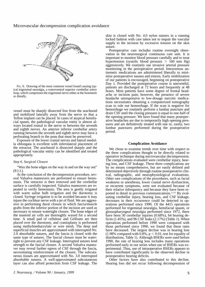
FIG. 7. Diagrams depicting how dissection and mobiliza-tion of the arterial loop depend on the anatomy of compres-sion. This figure demonstrates the microsurgical movementsthat are performed when a typical superior cerebellar arteryloop is found compressing the trigeminal nerve. The con-cepts of Teflon felt placement and proximal-to-distal sweep-ing movements of the felt along the nerve apply for lowercranial nerve decompressions as well. A: Before the vesselcan be moved, the arachnoid must be sharply dissected overthe entire length of the loop proximally and distally. B: Af-ter the vessel is freed, the vascular loop is lifted off the brain-stem at the rostral aspect of the nerve and a medium-sizedcigar-shaped piece of Teflon felt is placed between the ves-sel and the nerve. It is very important to position the distal
portion of the felt with the tips of the forceps. The Teflon felt should not be pushed into position by holding its proximalportion. C: After the Teflon felt is placed under the loop, the pledget is gently pushed in a proximal-to-distal fashionalong the nerve toward Meckel’s cave. This movement elevates the arterial loop and causes it to begin to rotate outwardfrom the ventral surface of the nerve. D: A second Teflon felt, approximately the same size, is placed where the firstfelt was originally positioned. Using the same proximal-to-distal sweeping motion, the felt should be advanced over thelength of the nerve toward Meckel’s cave. E: As the Teflon pledgets are advanced, the vascular loop progressivelyrotates from the ventral aspect of the nerve to the dorsal side. F: A third Teflon pledget is placed where the first felt wasoriginally positioned and, again, a proximal-to-distal sweeping movement along the trigeminal nerve flips the vascularloop to the dorsal aspect of the nerve. G: After the vascular loop is flipped to the dorsal surface of the nerve, pledgetsare placed between the vessel and the nerve.

the ninth and 10th cranial nerve, and the rate after decom-pression of the fifth cranial nerve was much less than thatobserved after treatment of hemifacial spasm (Table 2).The approach “turning the corner” to the ninth and 10thnerves, discussed previously, involves elevation of thecerebellar tonsils and a corridor along the floor of theocciput. This places no retraction on the seventh–eighthnerve complex. A common error is to approach the ninthand 10th nerves too superiorly, exposing the seventh andeighth nerves prematurely before moving inferior to theninth and 10th nerves. This route requires retraction of thecerebellum at the level of the seventh and eighth cranialnerves, often before visualization of these structures. Thesame is true for decompression of the fifth cranial nerve.The seventh–eighth nerve complex should not be ap-proached directly with subsequent dissection moving su-periorly to the fifth cranial nerve. The petrotentorial junc-tion is the proper corridor to approach the fifth nerve andthe seventh–eighth nerve complex should have little ten-sion from retraction. However, decompression of the fifthcranial nerve does require some retraction, which placestension on the seventh and eighth nerves and, hence, maylead to hearing loss. If during a fifth nerve decompressionthe BSERs begin to decline, it is often related to the teth-ering of the arachnoid to the seventh–eighth nerve com-plex. When delays are encountered, the surgeon shouldcontinue sharp arachnoidal dissection down to, and slight-ly below, the seventh–eighth nerve complex. This maneu-ver frequently will relieve the tension on the cochlearnerve and cause improvement in the BSERs.
Decompression of the lower cranial nerves, however,places relatively little tension on the seventh–eighth nervecomplex and is, therefore, associated with a minimal riskof hearing loss (none in our series) (Table 2). Decom-pression of the seventh or eighth nerve should also beapproached from above or below as described previously.This allows good visualization of the seventh and eighthnerves before retracting near their proximal origins.
When BSERs change during the procedure, it is usual-ly due to retraction. The first response of the surgeonshould be to reduce or remove retraction, or at leastchange the position of the retractor. We have found thisusually improves the BSERs. Constant surveillance of theretractor is imperative because it often shifts and is fre-quently only millimeters from the eighth cranial nerve.Occasionally the BSERs will change after decompressionand is not corrected with alterations in retraction. In thesecases, inspection of the entire length of the eighth nervewill often disclose impingement from a Teflon implant ordisplaced vessel. Appropriate alterations should then bemade. Finally, a change in BSERs may occur on closure
of the dura. Although this happens very rarely, the durashould always be reopened. Opening the dura usuallycauses the BSERs to return to baseline. In this situation,reexploration of the decompression and the eighth cranialnerve will often disclose tension on the nerve from a Tef-lon pad or displaced vessels, which somehow worsensafter the CSF is replaced and the dura is closed. Manip-ulation of any impingements on the eighth nerve andclosure of the dura can then be safely completed. Wehave also observed that small amounts of blood or cold sa-line irrigation on the cochlear nerve may adversely affectBSERs.
Cerebellar injuries, including hemorrhage and contu-sion, have also occurred with less frequency since 1990(0.87% compared with 0.45%, p , 0.01; Table 1). Limita-tion of the degree and duration of retraction remainsessential in avoiding cerebellar injury. The entire decom-pression procedure (from skin incision to skin closure)generally takes less than 2 hours and requires only a smallcorridor of exposure between the cerebellum and petroustemporal bone. This corridor is kept to a minimum by ade-quate exposure of the sigmoid sinus by mastoid boneremoval prior to durotomy. This allows a dural incisionvery close to the sigmoid sinus rather than a more posteri-or durotomy that requires more cerebellar retraction topermit visualization along the petrous temporal bone. Weplace rubber dams made from latex gloves on the cerebel-lar side of all cottonoids so that smooth gentle advance-ment can be performed. Also, the approach superiorlyand inferiorly allows CSF drainage from cisterns prior tosignificant retraction. An approach that leads straight inrequires more cerebellar tissue to be retracted and ex-poses the seventh–eighth nerve complex, rather than aCSF cistern, which can allow further relaxation of thecerebellum.
Avoidance of CSF leaks remains problematic aftertransgression of mastoid air cells and exposure of multipleoverlapping tissue planes. Our incidence of CSF leaks hasdeclined since 1990 from 2.44% to 1.85% (p , 0.01).Mastoid air cells are frequently opened to obtain adequatevisualization of the margin of the sigmoid sinus. Copiousamounts of bone wax should be applied before durotomyand after dural closure. The nuchal musculature does notextend above the digastric groove. Therefore, good surgi-cal technique should be applied and the muscular layersapproximated before fascial closure. Care should be takennot to include the galea in the deep muscle closure at theinferior aspect of the wound, so that a single layer of fas-cia is left to close along the entire length of the incision.This should be closed with interrupted sutures. An invert-ed, interrupted No. 3.0 absorbable closure of the subcuta-
J. Neurosurg. / Volume 90 / January, 1999
Microvascular decompression complication avoidance
7
TABLE 1Incidence of complications during microvascular decompression
of cranial nerves
Before 1990 Since 1990 TotalComplications (2420 ops) (1995 ops) (4415 ops)
cerebellar injury 21 (0.87%) 9 (0.45%) 30 (0.68%)
eighth nerve injury 48 (1.98%) 16 (0.80%) 64 (1.45%)
CSF leak 59 (2.44%) 37 (1.85%) 96 (2.17%)
TABLE 2Incidence of hearing loss following microvascular
decompression of cranial nerves*
Decom Before 1990 Since 1990 Total
CN V 22 of 1659 (1.33%) 9 of 1537 (0.59%) 31 of 3196 (0.97%)CN VII 26 of 692 (3.76%) 6 of 377 (1.59%) 32 of 1069 (2.99%)CN IX/X 0 of 69 (0.0%) 0 of 81 (0.0%) 0 of 150 (0.0%)total 48 of 2420 (1.98%) 15 of 1995 (0.75%) 63 of 4415 (1.43%)
* CN = cranial nerve; decom = decompression procedure.
neous tissues should also be watertight and should not beplaced until a Valsalva maneuver reveals a watertightgaleal closure. Postoperative CSF leaks usually resolvewith lumbar drainage, although a minority of cases requireoperative intervention including reexploration of the duralclosure and careful inspection of the mastoid air cells.
Conclusions
Since the inception of microvascular decompression,the procedure has undergone changes designed to improvesafety and efficacy. Implementation of neurophysiologicalmonitoring and meticulous attention to the microsurgicalanatomy of the posterior fossa have improved complica-tion rates for cerebellar injury and hearing loss to less than1%. We believe this six-step approach, combined with thesurgical wisdom gained from more than 4400 procedures,remains the key to successful outcomes.
References
1. Barker FG II, Jannetta PJ, Bissonette DJ, et al: The long-termoutcome of microvascular decompression for trigeminal neu-ralgia. N Engl J Med 334:1077–1083, 1996
2. Barker FG II, Jannetta PJ, Bissonette DJ, et al: Microvas-cular decompression for hemifacial spasm. J Neurosurg 82:201–210, 1995
3. Campbell E, Keedy C: Hemifacial spasm: a note on the etiolo-gy in two cases. J Neurosurg 4:342–347, 1947
4. Dandy WE: Concerning the cause of trigeminal neuralgia. AmJ Surg 24:447–455, 1934
5. Dandy WE: An operation for the cure of tic douloureux. Partialsection of the sensory root at the pons. Arch Surg 18:687–734,1929
6. Dandy WE: The treatment of trigeminal neuralgia by the cere-bellar route. Ann Surg 96:787–795, 1932
7. Day JD, Tschabitscher M: Anatomic position of the asterion.Neurosurgery 42:198–199, 1998
8. Gardner WJ, Miklos MV: Response of trigeminal neuralgia to“decompression” of the sensory root. Discussion of cause of tri-geminal neuralgia. JAMA 170:1773–1776, 1959
9. Gardner WJ, Sava GA: Hemifacial spasm—a reversible patho-physiologic state. J Neurosurg 19:240–247, 1962
10. Laine E, Nayrac P: Hemispasme facial guéri par interventionsur la fossa postérieure. Rev Neurol 80:38–40, 1948
11. Resnick DK, Jannetta PJ, Bissonnette D, et al: Microvasculardecompression for glossopharyngeal neuralgia. Neurosurgery36:64–69, 1995
12. Taarnhøj P: Decompression of the trigeminal root and the pos-terior part of the ganglion as treatment in trigeminal neuralgia.Preliminary communication. J Neurosurg 9:288–290, 1952
Manuscript received April 14, 1998.Accepted in final form September 8, 1998.Address reprint requests to: Peter J. Jannetta, M.D., Department
of Neurological Surgery, University of Pittsburgh Medical Center,200 Lothrop Street, Suite B-400 PUH, Pittsburgh, Pennsylvania15213.
M. R. McLaughlin, et al.
8 J. Neurosurg. / Volume 90 / January, 1999