Microtubule shuttles on kinesin-coated glass micro-wire...
8
Microtubule shuttles on kinesin-coated glass micro-wire tracks Kyongwan Kim & Andrew L. Liao & Aurélien Sikora & Daniel Oliveira & Hikaru Nakazawa & Mitsuo Umetsu & Izumi Kumagai & Tadafumi Adschiri & Wonmuk Hwang & Winfried Teizer Published online: 16 April 2014 # Springer Science+Business Media New York 2014 Abstract Gliding of microtubule filaments on surfaces coat- ed with the motor protein kinesin has potential applications for nano-scale devices. The ability to guide the gliding direction in three dimensions allows the fabrication of tracks of arbi- trary geometry in space. Here, we achieve this by using kinesin-coated glass wires of micrometer diameter range. Unlike previous methods in which the guiding tracks are fixed on flat two-dimensional surfaces, the flexibility of glass wires in shape and size facilitates building in-vitro devices that have deformable tracks. Keywords Microtubule . Kinesin . Molecular motility . Glass micro-wire . Lab-on-a-chip . Molecular delivery 1 Introduction Microtubules are cytoskeletal filaments formed by noncovalent self-assembly of tubulin dimers as building blocks. A tubulin dimer (46 Å×80 Å×65 Å) consists of α- and β-tubulin (Desai and Mitchison 1997; Nogales et al. 1999). A microtubule typically consists of 13 protofilaments self-assembled into a tubule 25 nm in diameter (Chretien et al. 1995). The motor protein kinesin ‘walks’ on the microtubule to carry out many vital functions in the cell, including intra- cellular transport and cell division (McIntosh et al. 2012; Hirokawa et al. 2009; Vale 2003). Kinesin uses adenosine triphosphate (ATP) as a fuel and its 8 nm step size corresponds to the size of the tubulin pitch forming the microtubule (Vale and Milligan 2000; Hwang and Lang 2009). Due to their physiological importance, pharmaceutical targeting of micro- tubules and kinesin is under intensive study for diseases such as Alzheimer’ s disease and cancer (Zhou and Giannakakou 2005; Craddock et al. 2012; Rath and Kozielski 2012). Moreover, by virtue of in-vitro formation of microtubules (Weisenberg 1972) and successful reconstruction of the kinesin/microtubule-based motility (Vale et al. 1985a, b), this bio-motile system has been utilized as a model system for the study of pattern formation driven by motor proteins (Nedelec et al. 1997; Schaller et al. 2010; Sumino et al. 2012). Unlike in traditional approaches where one passively observes self- organization of a dynamic system, motor proteins allow con- trolled experimental design, which is a significant benefit for the study of phase transitions in systems of self-driven com- ponents (Vicsek et al. 1995). In addition, the robust stepping process (8 nm stepsize for kinesin on microtubules (Coy et al. 1999)), activation at the Electronic supplementary material The online version of this article (doi:10.1007/s10544-014-9852-6) contains supplementary material, which is available to authorized users. K. Kim : A. L. Liao : A. Sikora : D. Oliveira : M. Umetsu : T. Adschiri : W. Teizer (*) WPI-Advanced Institute for Materials Research (AIMR), Tohoku University, Sendai 980-8577, Japan e-mail: [email protected] A. L. Liao : W. Hwang : W. Teizer Materials Science and Engineering, Texas A&M University, College Station, TX 77843-3003, USA H. Nakazawa : M. Umetsu : I. Kumagai Department of Biomolecular Engineering, Graduate School of Engineering, Tohoku University, Sendai 980-8579, Japan W. Hwang Department of Biomedical Engineering, Texas A&M University, College Station, TX 77843-3120, USA W. Hwang School of Computational Sciences, Korea Institute for Advanced Study, Seoul 130-722, South Korea W. Teizer Department of Physics and Astronomy, Texas A&M University, College Station, TX 77843-4242, USA Biomed Microdevices (2014) 16:501–508 DOI 10.1007/s10544-014-9852-6
Transcript of Microtubule shuttles on kinesin-coated glass micro-wire...

Microtubule shuttles on kinesin-coated glass micro-wire tracks
Kyongwan Kim & Andrew L. Liao & Aurélien Sikora & Daniel Oliveira & Hikaru Nakazawa &
Mitsuo Umetsu & Izumi Kumagai & Tadafumi Adschiri & Wonmuk Hwang & Winfried Teizer
Published online: 16 April 2014# Springer Science+Business Media New York 2014
Abstract Gliding of microtubule filaments on surfaces coat-ed with the motor protein kinesin has potential applications fornano-scale devices. The ability to guide the gliding directionin three dimensions allows the fabrication of tracks of arbi-trary geometry in space. Here, we achieve this by usingkinesin-coated glass wires of micrometer diameter range.Unlike previous methods in which the guiding tracks are fixedon flat two-dimensional surfaces, the flexibility of glass wiresin shape and size facilitates building in-vitro devices that havedeformable tracks.
Keywords Microtubule .Kinesin .Molecularmotility .Glassmicro-wire . Lab-on-a-chip .Molecular delivery
1 Introduction
Microtubules are cytoskeletal filaments formed bynoncovalent self-assembly of tubulin dimers as buildingblocks. A tubulin dimer (46 Å×80 Å×65 Å) consists of α-and β-tubulin (Desai and Mitchison 1997; Nogales et al.1999). A microtubule typically consists of 13 protofilamentsself-assembled into a tubule 25 nm in diameter (Chretien et al.1995). The motor protein kinesin ‘walks’ on the microtubuleto carry out many vital functions in the cell, including intra-cellular transport and cell division (McIntosh et al. 2012;Hirokawa et al. 2009; Vale 2003). Kinesin uses adenosinetriphosphate (ATP) as a fuel and its 8 nm step size correspondsto the size of the tubulin pitch forming the microtubule (Valeand Milligan 2000; Hwang and Lang 2009). Due to theirphysiological importance, pharmaceutical targeting of micro-tubules and kinesin is under intensive study for diseases suchas Alzheimer’s disease and cancer (Zhou and Giannakakou2005; Craddock et al. 2012; Rath and Kozielski 2012).Moreover, by virtue of in-vitro formation of microtubules(Weisenberg 1972) and successful reconstruction of thekinesin/microtubule-based motility (Vale et al. 1985a, b), thisbio-motile system has been utilized as a model system for thestudy of pattern formation driven by motor proteins (Nedelecet al. 1997; Schaller et al. 2010; Sumino et al. 2012). Unlike intraditional approaches where one passively observes self-organization of a dynamic system, motor proteins allow con-trolled experimental design, which is a significant benefit forthe study of phase transitions in systems of self-driven com-ponents (Vicsek et al. 1995).
In addition, the robust stepping process (8 nm stepsize forkinesin on microtubules (Coy et al. 1999)), activation at the
Electronic supplementary material The online version of this article(doi:10.1007/s10544-014-9852-6) contains supplementary material,which is available to authorized users.
K. Kim :A. L. Liao :A. Sikora :D. Oliveira :M. Umetsu :T. Adschiri :W. Teizer (*)WPI-Advanced Institute for Materials Research (AIMR), TohokuUniversity, Sendai 980-8577, Japane-mail: [email protected]
A. L. Liao :W. Hwang :W. TeizerMaterials Science and Engineering, Texas A&MUniversity, CollegeStation, TX 77843-3003, USA
H. Nakazawa :M. Umetsu : I. KumagaiDepartment of Biomolecular Engineering, Graduate School ofEngineering, Tohoku University, Sendai 980-8579, Japan
W. HwangDepartment of Biomedical Engineering, Texas A&M University,College Station, TX 77843-3120, USA
W. HwangSchool of Computational Sciences, Korea Institute for AdvancedStudy, Seoul 130-722, South Korea
W. TeizerDepartment of Physics and Astronomy, Texas A&M University,College Station, TX 77843-4242, USA
Biomed Microdevices (2014) 16:501–508DOI 10.1007/s10544-014-9852-6

single molecule level (Schnitzer and Block 1997), as well asthe intrinsic size of the bio-structures, are opening a newparadigm for nano/bio-mechanical device development.Although the landing of kinesin molecules on the microtubuletrack is a random event, the bound kinesin always moves in aspecific direction defined by the polarity of the microtubule.This peculiarity in kinesin motility is understood as a result ofthe broken symmetry in the binding between the kinesinmotor head and the tubulin lattice (Grant et al. 2011) as wellas the unidirectional force generation upon conformationalchanges in the kinesin motor head (Hwang et al. 2008;Lakkaraju and Hwang 2011). The asymmetric, processiveand autonomous movement of kinesin on a microtubule meetsthe requirements for a ‘molecular walker’ (von Delius andLeigh 2011).
Besides motility of individual kinesins on the microtubule(Sikora et al. 2012), a cooperative mode of transport can berealized in-vitro, where microtubules glide on kinesin-coatedsurfaces (Cohn et al. 1989; Howard et al. 1989). Collectiveoperation of the motor domains holding one microtubuleresults in its translocation, allowing its use as a potentialtransporter (Brunner et al. 2007). This cooperative mode hasa great advantage in that the distance of travel of microtubulesis several orders of magnitude longer compared to the runlengths of an individual kinesin (Agarwal and Hess 2010;Muthukrishnan et al. 2009). However, for a practical applica-tion of the bio-motile system randomness in the initial glidingdirection of microtubules still needs to be overcome. Namely,in order to apply gliding microtubules driven by molecularmotors to a nanotransport device for sorting, separation, orassembly of materials, it is essential to guide microtubulesalong predetermined pathways (van den Heuvel andDekker 2007). Various approaches to design guidingtracks have been investigated, including topographicallypatterned tracks (Hess et al. 2001; Hiratsuka et al. 2001),chemical patterning of the kinesin attachment sites(Clemmens et al. 2003), a combination of physical and chem-ical approaches (Cheng et al. 2005), and enclosedmicrofluidicchannels as means for directional confinement (van denHeuvel et al. 2006; Yokokawa et al. 2006).
In this work, we use a glass wire as a new type of guidingtrack for the kinesin-powered gliding of microtubules. A glasssurface is a traditional choice for bio-motile systems as amajority of the bio-motility research has been demonstratedwithin a thin glass chamber, the so-called flow cell. Thecentral idea of this work is the reduction in dimensionalityof motion from a two-dimensional surface to a quasi one-dimensional wire. Glass fibers have been widely used inoptical communication as a track to guide photons. Methodsto fabricate glass micro/nano wires and to shape them are wellestablished (Tong et al. 2003). Our approach of using glasswires for guiding microtubule motility thus has the followingadvantages: (1) Unlike previous methods in which guiding
tracks are rigidly defined within a two-dimensional surface,the glass-wire track performs its function essentially in three-dimensional space. (2) Whereas previous guiding tracks aremostly enclosing types in terms of geometrical configuration,our wire track is an exposed type. Thus, tracks are not inde-pendently isolated but can be coupled to each other so thatproteins on a track can interact with those on another track. (3)Glass wires are flexible at the micro/nano scale and each trackcan be manipulated individually in principle. These featurescan be useful for making reconfigurable devices for moleculartransport.
2 Methods
2.1 Glass wire
Glass wires were fabricated by a customized method (Tonget al. 2006). The experimental set-up and a schematic diagramof the procedure are shown in Fig. 1a and b, respectively. First,a sapphire rod (Optostar Ltd., Diameter: 0.97 mm±0.02 mm,Length: 100 mm) was heated by a butane torch. Once thetemperature of the rod was sufficient to melt glass, we broughtits tip in contact with a piece of coverslip in order to generate adroplet of melted glass held by the tip. We then broughtanother sapphire rod (Optostar Ltd., Diameter: 0.45 mm±0.02 mm, Length: 100 mm) in contact with the glass dropletwhile the temperature of the first rod was kept constant. Whilereducing the temperature by removing the flame slightly fromthe original position the thinner (second) sapphire rod wasdrawn until a silky glass wire, which formed between the twosapphire rods, disconnected. Because the melting point ofsapphire (~2,000 °C) is higher than the highest temperatureachievable with a butane torch (~1,400 °C) the sapphire rodsare almost permanently reusable.
Commercially available streptavidin coated quantum dots(Invitrogen Ltd. Qdot 655-streptavidin conjugates) exhibit astrong affinity for glass surfaces in an aqueous environment.The fabricated glass wires were immersed in a quantum dotsolution (diluted in PEM buffer: 80 mMPIPES, 1 mMEGTA,1 mM MgCl2) and then transferred into a droplet of PEMbuffer on a glass coverslip for fluorescence imaging.Exemplary quantum dot-decorated glass wires with lateraldimensions ~2.6 μm (determined at the intensity of 7,500 inFig. 1e) and ~0.6 μm (determined at the intensity of 3,100 inFig. 1f) are shown in Fig. 1c and d, respectively. The two endsof the wire in Fig. 1d are out-of-focus because the wire transitsthe focal plane (Supplementary Movie, SM01).
2.2 Flow cell
Flow cells including glass wires were assembled by a standardmethod using double-sided tape (3M 665) as a spacer (Noel
502 Biomed Microdevices (2014) 16:501–508

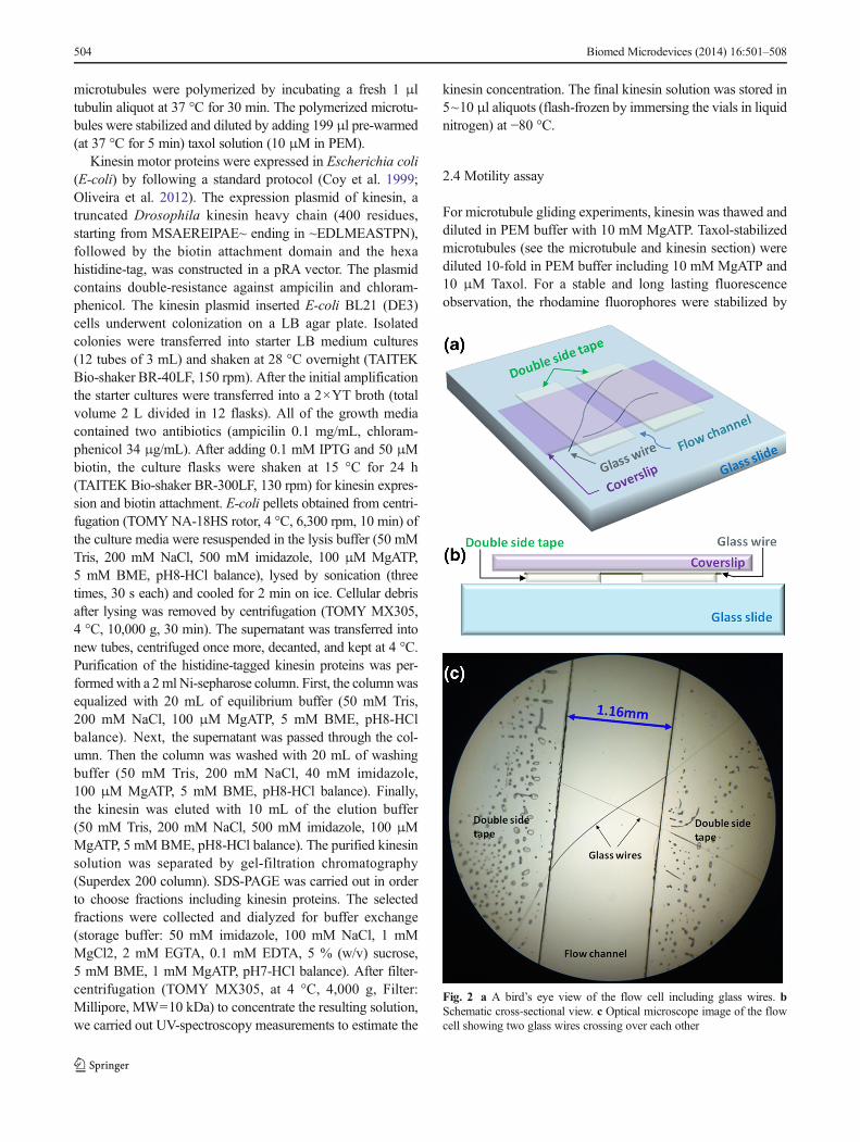
et al. 2009). First, we defined a flow channel on a glass slideusing double-sided tape. Next, we placed the prepared glasswire on the tape in a way that it crossed the channel. Generally,the taper-drawn glass wire gets gradually thinner towards theopen end. The thinner portion of the wire, which we put insidethe flow channel, is very flexible and hardly visible to thenaked eyes. Therefore, the glass wire was manipulated as itwas still attached to the sapphire rod. After putting the wire onthe tape, it was cut off the sapphire rod using a razor blade.Finally, the channel was capped with a glass coverslip (Fig. 2).
2.3 Microtubule and kinesin
Microtubules were polymerized from commercially availableporcine tubulin following a protocol described in previous work(Maloney et al. 2011). For fluorescence imaging, we used a 7:3mixture of bare and rhodamine-labeled tubulin (Cytoskeleton,Inc.). Tubulin stock solution (5 mg/mL) was prepared in PEMbuffer with 1 mM of GTP and glycerol at 6 % (v/v) and storedin 1 μl aliquots (flash-frozen by immersing the vials in liquidnitrogen) at −80 °C. For motility assay experiments
Fig. 1 (a) Photograph ofexperimental setup for taperingthe glass wire using a flame.(b) Schematic diagrams showingthe fabrication process of a glasswire. (c, d) Fluorescencemicroscope images of quantumdot decorated glass wires withlateral dimensions 2.56 μm (c)and 0.59 μm (d). The greencolor-coding (color online) for thequantum dots was arbitrarilychosen using Metamorph. (e)and (f) Intensity profiles along thewhite dotted lines in the images,(c) and (d), respectively
Biomed Microdevices (2014) 16:501–508 503
microtubules were polymerized by incubating a fresh 1 μltubulin aliquot at 37 °C for 30 min. The polymerized microtu-bules were stabilized and diluted by adding 199 μl pre-warmed(at 37 °C for 5 min) taxol solution (10 μM in PEM).
Kinesin motor proteins were expressed in Escherichia coli(E-coli) by following a standard protocol (Coy et al. 1999;Oliveira et al. 2012). The expression plasmid of kinesin, atruncated Drosophila kinesin heavy chain (400 residues,starting from MSAEREIPAE~ ending in ~EDLMEASTPN),followed by the biotin attachment domain and the hexahistidine-tag, was constructed in a pRA vector. The plasmidcontains double-resistance against ampicilin and chloram-phenicol. The kinesin plasmid inserted E-coli BL21 (DE3)cells underwent colonization on a LB agar plate. Isolatedcolonies were transferred into starter LB medium cultures(12 tubes of 3 mL) and shaken at 28 °C overnight (TAITEKBio-shaker BR-40LF, 150 rpm). After the initial amplificationthe starter cultures were transferred into a 2×YT broth (totalvolume 2 L divided in 12 flasks). All of the growth mediacontained two antibiotics (ampicilin 0.1 mg/mL, chloram-phenicol 34 μg/mL). After adding 0.1 mM IPTG and 50 μMbiotin, the culture flasks were shaken at 15 °C for 24 h(TAITEK Bio-shaker BR-300LF, 130 rpm) for kinesin expres-sion and biotin attachment. E-coli pellets obtained from centri-fugation (TOMY NA-18HS rotor, 4 °C, 6,300 rpm, 10 min) ofthe culture media were resuspended in the lysis buffer (50 mMTris, 200 mM NaCl, 500 mM imidazole, 100 μM MgATP,5 mM BME, pH8-HCl balance), lysed by sonication (threetimes, 30 s each) and cooled for 2 min on ice. Cellular debrisafter lysing was removed by centrifugation (TOMY MX305,4 °C, 10,000 g, 30 min). The supernatant was transferred intonew tubes, centrifuged once more, decanted, and kept at 4 °C.Purification of the histidine-tagged kinesin proteins was per-formedwith a 2ml Ni-sepharose column. First, the columnwasequalized with 20 mL of equilibrium buffer (50 mM Tris,200 mM NaCl, 100 μM MgATP, 5 mM BME, pH8-HClbalance). Next, the supernatant was passed through the col-umn. Then the column was washed with 20 mL of washingbuffer (50 mM Tris, 200 mM NaCl, 40 mM imidazole,100 μM MgATP, 5 mM BME, pH8-HCl balance). Finally,the kinesin was eluted with 10 mL of the elution buffer(50 mM Tris, 200 mM NaCl, 500 mM imidazole, 100 μMMgATP, 5 mM BME, pH8-HCl balance). The purified kinesinsolution was separated by gel-filtration chromatography(Superdex 200 column). SDS-PAGE was carried out in orderto choose fractions including kinesin proteins. The selectedfractions were collected and dialyzed for buffer exchange(storage buffer: 50 mM imidazole, 100 mM NaCl, 1 mMMgCl2, 2 mM EGTA, 0.1 mM EDTA, 5 % (w/v) sucrose,5 mM BME, 1 mM MgATP, pH7-HCl balance). After filter-centrifugation (TOMY MX305, at 4 °C, 4,000 g, Filter:Millipore, MW=10 kDa) to concentrate the resulting solution,we carried out UV-spectroscopy measurements to estimate the
kinesin concentration. The final kinesin solution was stored in5~10 μl aliquots (flash-frozen by immersing the vials in liquidnitrogen) at −80 °C.
2.4 Motility assay
For microtubule gliding experiments, kinesin was thawed anddiluted in PEM buffer with 10 mM MgATP. Taxol-stabilizedmicrotubules (see the microtubule and kinesin section) werediluted 10-fold in PEM buffer including 10 mM MgATP and10 μM Taxol. For a stable and long lasting fluorescenceobservation, the rhodamine fluorophores were stabilized by
Fig. 2 a A bird’s eye view of the flow cell including glass wires. bSchematic cross-sectional view. c Optical microscope image of the flowcell showing two glass wires crossing over each other
504 Biomed Microdevices (2014) 16:501–508

adding BME (β-mercaptoethanol, 0.5 % (v/v)) and a typicalanti-fade system (20 μg/mL glucose oxidase, 8 μg/mL cata-lase, 20 mM glucose) into the PEM buffer (Maloney et al.2011). First, the glass surfaces within a flow cell including aglass wire were exposed to kinesin molecules by introducing20 μL of kinesin solution (~ 4 μM kinesin, 10 mM ATP inPEM buffer). A pipette and a piece of filter paper were used toinject the fluid to one open side of the flow cell and to absorb itfrom the other side, respectively. The flow cell was incubatedat room temperature for 5 min, followed by introduction of a20-μL microtubule solution. Microtubules were imaged usinga fluorescence microscope (Olympus, IX71) equipped with aCCD camera (Hamamatsu, ImagEM) and rhodamine filter set
(Omega Optical, Inc., XF204). Image analyses were carriedout using Metamorph and ImageJ. Activity of molecularmotors fixed on a surface is very sensitive to interaction withthe surface. For the optimal functionality and effective con-sumption of the kinesin proteins in microtubule gliding as-says, casein is typically employed to pretreat glass surfaces(Maloney et al. 2011). However, inclusion of casein in ourexperimental procedure often suppressed binding of microtu-bules to the kinesin-treated surface, possibly due to a non-optimal casein solution. For the present work, we coated theglass surface densely with kinesin as an alternative way ofsurface passivation (Howard et al. 1989; Liu et al. 2011).Assuming that all kinesin molecules in solution within the
Fig. 4 Fluorescence images showing time evolution of the distribution ofmicrotubules in a flow cell (Supplementary Movie 03).White dotted linesdenote the glass wire identified in panel (b). (a) and (h) The focal planewas set on the coverslip in order to observe microtubules bound on thecoverslip. (b–g) The focal plane was set on the upper portion of the glass
wire to observe microtubules bound on the top. The arrow in panel (b)indicates the reference vector used to measure the gliding direction ofmicrotubules in Fig. 5. Numbers in each image indicate time (min: sec).Arrows in panels (c–g) are guides for the eye for a gliding microtubule
Fig. 3 Fluorescence images of microtubules in a flow cell including aglass wire. Each image shows the same region (area: ~50 μm × 50 μm).The level of the focal plane is depicted below each image. The whitedotted lines in (a, c) were added as guidelines for the glass wire based onthe image b. (a) Microtubules on the coverslip. (b) Focal plane at the
middle of the glass wire. The light reflected from the glass wire’s edgemakes it easy to identify the outline. (c) Microtubules bound to the top ofthe glass wire. The cyan color-coding (color online) for microtubules wasarbitrarily chosen using Metamorph
Biomed Microdevices (2014) 16:501–508 505

flow cell attach to the glass surfaces, the kinesin surfacedensity from the 4 μM kinesin solution is estimated to be108,000 molecules per 1 μm2. This is well beyond the satu-ration limit determined by the size of a single kinesin motorhead because it corresponds to one kinesin molecule in an areaof ~3 nm×3 nm which is smaller than the size of a kinesinmotor head (~8 nm in diameter) (Kozielski et al. 1997).
3 Results and discussion
Figure 3 shows fluorescence microscope images of microtu-bules in a flow cell including a glass wire, captured at threedifferent focal planes of the same area (The schematic diagrambelow the image shows the focal plane. See SupplementaryMovie, SM02). On the coverslip, only microtubules bound tothe surface are clearly recognized (Fig. 3a). When the focalplane is near the center of the glass wire, most microtubulesincluding those on the glass wire are out of focus, but theoutline of the wire can be identified (Fig. 3b). The whiteguidelines used in Fig. 3a and c were obtained from Fig. 3b.Figure 3c shows microtubules attached to the top of the glasswire.With proper adjustment of the position of focal plane andcontrast, the microtubules on the glass wire can visually beseparated from the background objects for clear observation.
The gliding motion of microtubules confined by the glasswire (Supplementary Movie, SM03) is visualized by eightimages in Fig. 4, where the focal plane was set around theglass wire. The white dashed lines again indicate the glasswire identified in Fig. 4b. The focal plane was formed at thecoverslip surface for the first frame (Fig. 4a) and the last frame(Fig. 4h) where the change in the distribution of microtubulesis due to the gliding motion on the kinesin-coated coverslip. InFig. 4b the focal plane was set around the glass wire for itsidentification. The focal plane was elevated to the upperportion of the glass wire for the other fiveframes (Fig. 4c–g)to detect microtubules gliding on top of the wire.
In order to characterize the general aspect of the motility,we observed microtubules gliding on a region of the coverslip(area: ~50 μm×50 μm) away from the glass wire(Supplementary Movie, SM12). Note that all observations inthis work were made in a single flow cell. Therefore, there wasno significant difference in environmental conditions betweenobservations. One end of each microtubule was tracked for3 min. The selected ends were marked every 30 s.Displacement was defined by the length of a straight lineconnecting the initial mark and the final mark. The averagespeed was estimated by dividing the linear displacement bythe 30-s time interval between frames. The direction of motionwas measured relative to the 12 o’clock direction of the image(angle increases counterclockwise). Tracking continued untilthe microtubule tip moved out of the field of view, overlappedwith other microtubules, or detached from the glass surface.
Similarly, we analyzed the motion of microtubules on tendifferent portions of the glass wire whose diameter variedfrom ~2.6 μm to ~6.5 μm (See Supplemental Movies,SM02–SM11). In this case, the direction of motion was mea-sured relative to the vector pointing upwards parallel to theglass wire (arrow in Fig. 4b; the angle increases againcounterclockwise.)
Fig. 5 (a) Distribution of microtubule gliding velocities. Squares(Triangles) are for microtubules gliding on the coverslip (glass wire).(b) Velocity distribution sorted by wire diameter. The orientation of theglass wire is defined relative to the arrow in Figure 4b. (c) Histograms ofmicrotubule gliding speeds. The average speed (v ) for the two differentcases is indicated in the graph with respective standard deviations (σ).Short dashed line (Dash-dotted line) for microtubules gliding on thecoverslip (glass wire)
506 Biomed Microdevices (2014) 16:501–508
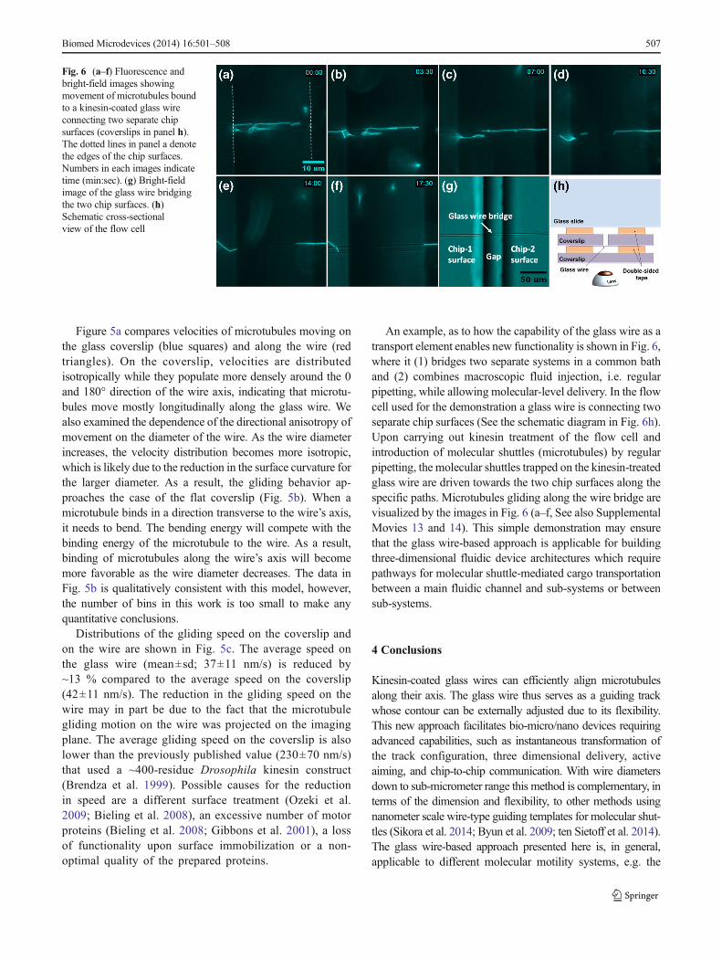
Figure 5a compares velocities of microtubules moving onthe glass coverslip (blue squares) and along the wire (redtriangles). On the coverslip, velocities are distributedisotropically while they populate more densely around the 0and 180° direction of the wire axis, indicating that microtu-bules move mostly longitudinally along the glass wire. Wealso examined the dependence of the directional anisotropy ofmovement on the diameter of the wire. As the wire diameterincreases, the velocity distribution becomes more isotropic,which is likely due to the reduction in the surface curvature forthe larger diameter. As a result, the gliding behavior ap-proaches the case of the flat coverslip (Fig. 5b). When amicrotubule binds in a direction transverse to the wire’s axis,it needs to bend. The bending energy will compete with thebinding energy of the microtubule to the wire. As a result,binding of microtubules along the wire’s axis will becomemore favorable as the wire diameter decreases. The data inFig. 5b is qualitatively consistent with this model, however,the number of bins in this work is too small to make anyquantitative conclusions.
Distributions of the gliding speed on the coverslip andon the wire are shown in Fig. 5c. The average speed onthe glass wire (mean±sd; 37±11 nm/s) is reduced by~13 % compared to the average speed on the coverslip(42±11 nm/s). The reduction in the gliding speed on thewire may in part be due to the fact that the microtubulegliding motion on the wire was projected on the imagingplane. The average gliding speed on the coverslip is alsolower than the previously published value (230±70 nm/s)that used a ~400-residue Drosophila kinesin construct(Brendza et al. 1999). Possible causes for the reductionin speed are a different surface treatment (Ozeki et al.2009; Bieling et al. 2008), an excessive number of motorproteins (Bieling et al. 2008; Gibbons et al. 2001), a lossof functionality upon surface immobilization or a non-optimal quality of the prepared proteins.
An example, as to how the capability of the glass wire as atransport element enables new functionality is shown in Fig. 6,where it (1) bridges two separate systems in a common bathand (2) combines macroscopic fluid injection, i.e. regularpipetting, while allowing molecular-level delivery. In the flowcell used for the demonstration a glass wire is connecting twoseparate chip surfaces (See the schematic diagram in Fig. 6h).Upon carrying out kinesin treatment of the flow cell andintroduction of molecular shuttles (microtubules) by regularpipetting, the molecular shuttles trapped on the kinesin-treatedglass wire are driven towards the two chip surfaces along thespecific paths. Microtubules gliding along the wire bridge arevisualized by the images in Fig. 6 (a–f, See also SupplementalMovies 13 and 14). This simple demonstration may ensurethat the glass wire-based approach is applicable for buildingthree-dimensional fluidic device architectures which requirepathways for molecular shuttle-mediated cargo transportationbetween a main fluidic channel and sub-systems or betweensub-systems.
4 Conclusions
Kinesin-coated glass wires can efficiently align microtubulesalong their axis. The glass wire thus serves as a guiding trackwhose contour can be externally adjusted due to its flexibility.This new approach facilitates bio-micro/nano devices requiringadvanced capabilities, such as instantaneous transformation ofthe track configuration, three dimensional delivery, activeaiming, and chip-to-chip communication. With wire diametersdown to sub-micrometer range this method is complementary, interms of the dimension and flexibility, to other methods usingnanometer scale wire-type guiding templates for molecular shut-tles (Sikora et al. 2014; Byun et al. 2009; ten Sietoff et al. 2014).The glass wire-based approach presented here is, in general,applicable to different molecular motility systems, e.g. the
Fig. 6 (a–f) Fluorescence andbright-field images showingmovement of microtubules boundto a kinesin-coated glass wireconnecting two separate chipsurfaces (coverslips in panel h).The dotted lines in panel a denotethe edges of the chip surfaces.Numbers in each images indicatetime (min:sec). (g) Bright-fieldimage of the glass wire bridgingthe two chip surfaces. (h)Schematic cross-sectionalview of the flow cell
Biomed Microdevices (2014) 16:501–508 507

actomyosin system which also has been extensively investigatedfor molecular motor-based devices. Characteristics, such as arange of motion speeds and flexural rigidity, of each of thesystems are complementary to each other (Agarwal and Hess2010; Månsson 2012). Thus the glass wire templates, with itsinherent simplicity of production and handling, may be benefi-cial not only for interfacing macroscale fluidic delivery withmolecular-level transportation, but also for potential hybridiza-tion of different motility systems. Furthermore, the cylindricalcurvature of a glass wire may also allow the study of fundamen-tal phenomena such as the effect of geometrical constraints onmicrotubule dynamics and assembly, which has relevance to thebehaviors in the cell such as in tunneling nanotubes (Gerdes andCarvalho 2008). Further quantification of the measurements andmore detailed analysis with a wider range of wire diameters mayyield additional information about the gliding behavior of mi-crotubules on this quasi one-dimensional track.
Acknowledgments We gratefully acknowledge support from theWorld Premier International Research Center Initiative (WPI), MEXT,Japan. We would like to thank Dr. Hideaki Sanada for generously pro-viding the kinesin plasmid.
References
A. Agarwal, H. Hess, Prog. Polym. Sci. 35, 252 (2010)P. Bieling, I.A. Telley, J. Piehler, T. Surrey, EMBO Rep. 9, 1121 (2008)K.M. Brendza, D.J. Rose, S.P. Gilbert, W.M. Saxton, J. Biol. Chem. 274,
31506 (1999)C. Brunner, C. Wahnes, V. Vogel, Lab Chip 7, 1263 (2007)K.-E. Byun, K. Heo, S. Shim, H.-J. Choi, S. Hong, Small 5, 2659 (2009)L.J. Cheng, M.T. Kao, E. Meyhofer, L.J. Guo, Small 1, 409 (2005)D. Chretien, S.D. Fuller, E. Karsenti, J. Cell Biol. 129, 1311 (1995)J. Clemmens, H. Hess, R. Lipscomb, Y. Hanein, K.F. Böhringer, C.M.
Matzke, G.D. Bachand, B.C. Bunker, V. Vogel, Langmuir 19, 10967(2003)
S.A. Cohn, A.L. Ingold, J.M. Scholey, J. Biol. Chem. 264, 4290 (1989)D.L. Coy, M. Wagenbach, J. Howard, J. Biol. Chem. 274, 3667 (1999)T.J.A. Craddock, J.A. Tuszynski, D. Chopra, N. Casey, L.E. Goldstein,
S.R. Hameroff, R.E. Tanzi, PLoS One 7, e33552 (2012)A. Desai, T.J. Mitchison, Annu. Rev. Cell Dev. Biol. 13, 83 (1997)H.H. Gerdes, R.N. Carvalho, Curr. Opin. Cell Biol. 20, 470 (2008)F. Gibbons, J.F. Chauwin, M. Desposito, J.V. Jose, Biophys. J. 80, 2515
(2001)B.J. Grant, D.M. Gheorghe, W. Zheng, M. Alonso, G. Huber, M. Dlugosz,
J.A. McCammon, R.A. Cross, PLoS Biol. 9, e1001207 (2011)H. Hess, J. Clemmens, D. Qin, J. Howard, V.Vogel, Nano Lett. 1, 235 (2001)Y. Hiratsuka, T. Tads, K. Oiwa, T. Kanayama, T.Q.P. Uyeda, Biophys. J.
81, 1555 (2001)
N. Hirokawa, Y. Noda, Y. Tanaka, S. Niwa, Nat. Rev. Mol. Cell Biol. 10,682 (2009)
J. Howard, A.J. Hudspeth, R.D. Vale, Nature 342, 154 (1989)W. Hwang, M.J. Lang, Cell Biochem. Biophys. 54, 11 (2009)W. Hwang, M.J. Lang, M. Karplus, Structure 16, 62 (2008)F. Kozielski, S. Sack, A. Marx, M. Thormählen, E. Schönbrunn, V. Biou,
A. Thompson, E.M. Mandelkow, E. Mandelkow, Cell 91, 985(1997)
S.K. Lakkaraju, W. Hwang, Biophys. J. 101, 1105 (2011)L. Liu, E. Tuzel, J.L. Ross, J. Phys. Condens. Matter 23, 374104 (2011)A. Maloney, L.J. Herskowitz, S.J. Koch, PLoS One 6, e19522 (2011)A. Månsson, J. Muscle Res. Cell Motil. 33, 219 (2012)J.R. McIntosh, M.I. Molodtsov, F.I. Ataullakhanov, Q. Rev. Biophys. 45,
147 (2012)G. Muthukrishnan, Y. Zhang, S. Shastry, W.O. Hancock, Curr. Biol. 19,
442 (2009)F.J. Nedelec, T. Surrey, A.C. Maggs, S. Leibler, Nature 389, 305 (1997)J.A. Noel, W. Teizer, W. Hwang, ACS Nano 3, 1938 (2009)E. Nogales, M. Whittaker, R.A. Milligan, K.H. Downing, Cell 96, 79
(1999)D. Oliveira, D.-M. Kim, M. Umetsu, I. Kumagai, T. Adschiri, W. Teizer,
J. Appl. Phys. 112, 124703 (2012)T. Ozeki, V. Verma, M. Uppalapati, Y. Suzuki, M. Nakamura, J.M.
Catchmark, W.O. Hancock, Biophys. J. 96, 3305 (2009)O. Rath, F. Kozielski, Nat. Rev. 12, 527 (2012)V. Schaller, C. Weber, C. Semmrich, E. Frey, A.R. Bausch, Nature 467,
73 (2010)M.J. Schnitzer, S.M. Block, Nature 388, 386 (1997)A. Sikora, D. Oliveira, K. Kim, L.A. Liao, M. Umetsu, I.
Kumagai, T. Adschiri, W. Hwang, W. Teizer, Chem. Lett. 41,1215 (2012)
A. Sikora, J. Ramón-Azcón, K. Kim, K. Reaves, H. Nakazawa, M.Umetsu, I. Kumagai, T. Adschiri, H. Shiku, T. Matsue, W. Hwang,W. Teizer, Nano Lett. 14, 876 (2014)
Y. Sumino, K.H. Nagai, Y. Shitaka, D. Tanaka, K. Yoshikawa, H. Chaté,K. Oiwa, Nature 483, 448 (2012)
L. ten Sietoff, M. Lard, J. Generosi, H.S. Andersson, H. Linke, A.Månsson, Nano Lett. 14, 737 (2014)
L. Tong, R.R. Gattass, J.B. Ashcom, S. He, J. Lou, M. Shen, I. Maxwell,E. Mazur, Nature 426, 816 (2003)
L. Tong, L. Hu, J. Zhang, J. Qiu, Q. Yang, J. Lou, Y. Shen, J. He, Z. Ye,Opt. Express 14, 82 (2006)
R.D. Vale, Cell 112, 467 (2003)R.D. Vale, R.A. Milligan, Science 288, 88 (2000)R.D. Vale, T.S. Reese, M.P. Sheetz, Cell 42, 39–50 (1985a)R.D. Vale, B.J. Schnapp, T.S. Reese, M.P. Sheetz, Cell 40, 559 (1985b)M.G.L. van den Heuvel, C. Dekker, Science 317, 333 (2007)M.G.L. van den Heuvel, M.P. de Graaff, C. Dekker, Science 312, 910
(2006)T. Vicsek, A. Czirok, E. Ben-Jacob, I. Cohen, O. Shoches, Phys. Rev.
Lett. 75, 1226 (1995)M. von Delius, D.A. Leigh, Chem. Soc. Rev. 40, 3656 (2011)R.C. Weisenberg, Science 177, 1104 (1972)R. Yokokawa, Y. Yoshida, S. Takeuchi, T. Kon, H. Fujita,
Nanotechnology 17, 289 (2006)J. Zhou, P. Giannakakou, Curr. Med. Chem. 5, 65 (2005)
508 Biomed Microdevices (2014) 16:501–508