MICROSWITCHES SELECTION GUIDE...
1
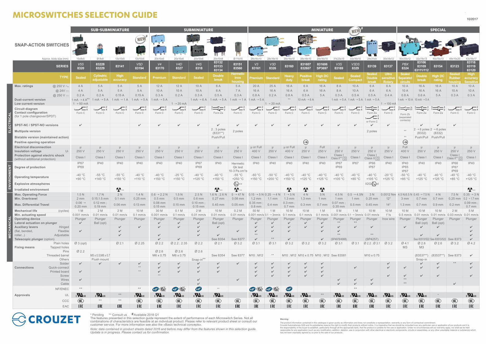
SUB-SUBMINIATURE SUBMINIATURE MINIATURE SPECIAL SNAP-ACTION SWITCHES Approx. body size (mm) 15x8x5 Ø 8x8 13x10x5 13x10x5 20x10x6 20x10x6 20x10x6 20x10x6 Ø 11x15 28x16x10 28x16x10 28x16x10 28x16x10 29x16x10 31x23x10 33x16x10 24x31x9 30x18x12 50x30x12 32x19x13 40x19x13 49x10x20 43x18x17 SERIES V5S 8320 83228 83229 83141 V5D 83194 V4 83170 V4D 8327 V4S 8318 83132 83133 83134 83151 83560 V3 83161 V3D 8326 83160 831607 832607 831606 SP3697 V3S 83169 V3DS 8329 83139 83137 PBX 8324 83106 83109 83111/112 83154 83123 83118 83119 83120 TYPE Sealed Cylindric adjustable High accuracy Standard Premium Standard Sealed Double break Hermetic Inox housing Premium Standard Heavy duty Positive break High DC rating Sealed Sealed Compact Sealed Double break Ultra sensitive Rotary Sealed Separated circuits Double break High DC rating Sealed Rubber housing High accuracy Sensitive Max. ratings @ 250 V a 4 A 5 A 5 A 5 A 12 A 12 A 10 A 6 A 5 A 20 A 25 A 16 A 6 A 16 A 8 A 10 A 6 A 6 A 10 A 16 A 16 A 10 A 10 A @ 24V c 4 A 5 A 5 A 5 A 10 A 10 A 10 A 6 A 7 A 16 A 16 A 16 A 6 A 16 A 8 A 10 A 6 A 6 A 10 A 16 A 16 A 10 A 10 A @ 250 V c 0.2 A 0.2 A 0.15 A 0.15 A 0.3 A 0.2 A 0.3 A 0.5 A 0.3 A 0.8 A 0.2 A 0.8 A 0.5 A 5 A 0.3 A 0.5 A 0.5 A 0.4 A 0.8 A 0.6 A 5 A 0.3 A 0.3 A Dual-current version 1 mA ➝ 4 A** 1 mA ➝ 5 A 1 mA ➝ 1 A 1 mA ➝ 5 A 1 mA ➝ 5 A 1 mA ➝ 6 A 1 mA ➝ 5 A 1 mA ➝ 1 A 1 mA ➝ 5 A ** 10 mA ➝ 6 A 1 mA ➝ 5 A 1 mA ➝ 5 A 1 mA ➝ 5 A 1 mA ➝ 10 A 10 mA ➝ 5 A Low current version 1 ➝ 50 mA 1 ➝ 20 mA 1 ➝ 20 mA 1 ➝ 100 mA Circuit diagram Contact configuration (for 1 pole changeover/SPDT) 1 4 2 1 4 2 1 4 2 1 4 2 1 4 2 1 4 2 1 4 2 1 3 2 4 1 4 2 1 4 2 1 4 2 1 4 2 1 4 2 1 4 2 1 4 2 1 4 2 1 3 2 4 1 4 2 21 22 13 14 1 3 2 4 1 3 2 4 1 4 2 1 4 2 Form C Form C Form C Form C Form C Form C Form C Form Za Form C Form C Form C Form C Form C Form C Form C Form C Form Za Form C Form Zb (separated contacts) Form Za Form Za Form C Form C 1 4 2 or Form C SPST-NC / SPST-NO versions 4 4 4 4 4 4 4 4 4 4 4 4 4 4 4 4 4 4 4 Multipole version 2 ; 3 poles (8331**) 2 poles 2 poles ** 2 ➝ 6 poles (8332) 2 ➝ 6 poles (8332) Bistable version (maintained action) Push/Pull ** Push/Pull Push/Pull Positive opening operation Electrical disconnection µ µ µ µ µ µ µ µ µ µ or Full µ µ or Full µ Full µ µ µ µ Full µ µ µ µ Insulation voltage Ui 250 V 250 V 250 V 250 V 250 V 250 V 250 V 250 V 250 V 400 V 250 V 400 V 250 V 250 V 250 V 250 V 250 V 250 V 400 V 250 V 250 V 250 V 250 V Protection against electric shock (without additional protection) Class I Class I Class I Class I Class I Class I Class I Class I Class I Class I Class I Class I Class I Class I Class I Class Il** Class I Class I Class Il Class I Class I Class I Class I Class I Class Il** Class I Degree of protection IP67 IP40 IP40 IP40 IP40 IP40 IP67 IP40 Hermetic Qk test 10-3 Pa.cm 3 /s IP40 IP40 IP40 IP40 IP40 IP67 IP67 IP66 IP40 IP40 IP40 IP40 IP66 IP40 IP69 IP69 IP69 IP67 IP65 IP67 IP69 IP67 Operating temperature -40 °C -55 °C -55 °C -40 °C -40 °C -25 °C -40 °C -40 °C -55 °C -60 °C -50 °C -40 °C -40 °C -40 °C -40 °C -40 °C -40 °C -20 °C -50 °C -40 °C -40 °C -40 °C -40 °C +90 °C +140 °C +150 °C +110 °C +150 °C +150 °C +125 °C +150 °C +250 °C +150 °C +200 °C +150 °C +125 °C +125 °C +105 °C +85 °C +105 °C +125 °C +85 °C +125 °C +125 °C +85 °C +125 °C Explosive atmospheres ** II2G d Irradiated environment ** ** ** ** Max. Operating Force 1.5 N 1.7 N 2 N 1.4 N 0.6 ➝ 2.2 N 1.5 N 2.5 N 1.6 N ; 2.6 N 5 ➝ 47 N 0.15 ➝ 5 N 0.25 ➝ 4 N 1 ➝ 5 N 4 N 5 N 4.5 N 0.5 ➝ 4.5N 3 N 0.0012 Nm 4.5 N;6.5 N 0.45 ➝ 7.5 N 4 N 7.5 N 0.35 ➝ 3 N Min. Overtravel 2 mm 0.15;1.5 mm 0.1 mm 0.25 mm 0.5 mm 0.5 mm 0.6 mm 0.27 mm 0.08 mm 1.2 mm 1.1 mm 1.3 mm 1.3 mm 1 mm 1 mm 1 mm 0.25 mm 12° 3 mm 0.7 mm 0.7 mm 0.25 mm 0.2 ➝ 1.7 mm Max. Differential Travel 0.06 ➝ 0.20 mm 0.12 mm ; 0.19 mm 0.06 mm 0.13 mm 0.08 mm 0.15 mm 0.15 mm 0.10 mm ; 0.15 mm 0.45 mm 0.05 mm 0.35 mm ; 0.8 mm 0.4 mm 0.3 mm ; 0.7 mm 0.3 mm 0.7 mm 0.07 mm ; 0.35 mm 0.5 mm 0.45 mm 14° 1.3 mm 0.7 mm 0.9 mm 0.2 mm 0.09 mm ; 0.7 mm Mechanical life (cycles) 1 M 2 M 2 M 10 M 30 M 0.1 M 2 M 10 M 0.2 M 50 M 1 M 10 M 10 M 1 M 5 M 1 M 10 M 10 M 10 M 10 M 10 M 2 M 5 M Min. actuating speed 0.001 mm/s 0.01 mm/s 0.01 mm/s 0.1 mm/s 0.001 mm/s 0.1 mm/s 0.01 mm/s 0.01 mm/s 0.01 mm/s 0.001 mm/s 0.1 ➝ 3mm/s 0.1 mm/s 0.1 mm/s 0.1 mm/s 0.001 mm/s 0.1 ➝ 3mm/s 0.01 mm/s 1°/s 0.5 mm/s 0.01 mm/s 0.01 mm/s 0.03 mm/s 0.01 mm/s Operating device Plunger Plunger Plunger Plunger Plunger Plunger Plunger Plunger Plunger Plunger Plunger Plunger Plunger Plunger Plunger Plunger Plunger Inox wire Plunger Plunger Plunger Plunger Plunger Lateral actuation on plunger 4 Ball (opt) 4 4 4 Ball (opt) 4 4 4 4 4 ** ** Ball (opt) Ball (opt) Auxiliary levers Hinged 4 4 4 4 4 4 4 4 4 4 4 4 4 4 4 4 4 4 (flat, bended, Flexible 4 4 4 4 4 4 4 4 4 4 roller...) Adjustable 4 4 4 4 ** ** ** 4 4 4 Telescopic plunger (option) 4 4 4 See 8354 See 8377 4 ** 4 4 (SP4978/4988) (SP4257) See 83513/522 See 83513/522 See 8373 4 Plain holes Ø 3 (opt) Ø 2.1 Ø 2.25 Ø 2.2 Ø 2.2 ; 2.35 Ø 2.2 Ø 2.1 Ø 3.2 Ø 3.1 Ø 3.1 Ø 3.2 Ø 3.2 Ø 3.2 Ø 3.1 Ø 3.1 Ø 2.2 ; Ø 3.1 Ø 3.2 Ø 4.1 Ø 2.6 Ø 2.6 Ø 3.2 Ø 4.2 Fixing means Tapped holes M3 M3 Pins Ø 2.2 Ø 2.6 Ø 2.6 Ø 2.6 Threaded barrel M5 x 0.5;M8 x 0.7 M6 x 0.75 M6 x 0.75 See 8354 See 8377 M10 ; M12 ** M10 ; M12 M10 x 0.75 M10 ; M12 See 83581 M10 x 0.75 (83537**) (83537**) See 8373 4 Others Flush mount Snap-in** Snap-in Solder 4 4 4 4 4 4 4 4 4 4 4 4 4 4 4 4 4 ** 4 Connections Quick-connect ** 4 4 4 4 4 4 4 4 4 4 4 4 4 4 4 Printed board 4 ** 4 4 4 4 4 4 4 4 4 Screw ** 4 4 4 4 4 4 4 4 4 4 Wires 4 4 4 4 4 4 ** Cable 4 4 4 4 ** 4 NF/ENEC ** ** ** ** Approvals UL ** ** * CCC ** ** EAC MICROSWITCHES SELECTION GUIDE * Pending ** Consult us Available 2018 Q1 The features presented in this selection guide represent the extent of performance of each Microswitch Series. Not all combinations of characteristics are feasible at an individual product. Please refer to relevant product sheet or consult our customer service. For more information see also the «Basic technical concepts». Note: data contained in product sheets dated 2016 and before may differ from the features shown in this selection guide. Update is in progress. Please contact us for confirmation. ELECTRICAL ENVIRONMENT MECHANICAL 10/2017 # # # Warning: The product information contained in this catalogue is given purely as information and does not constitute a representation, warrantly or any form of contractual commitment. Crouzet Automatismes SAS and its subsidiaries reserve the right to modify their products without notice. It is imperative that we should be consulted over any particular use or application of our products and it is the responsability of the buyer to establish, particularly through all the appropriate tests, that the product is suitable for the use or application. Under no circumstances will our warranty apply, nor shall we be held responsible for any application (such as any modification, addition, deletion, use in conjunction with other electrical or electronic components, circuits or assemblies, or any other unsuitable material or substance) which has not been expressly agreed by us prior to the sale of our products.
Transcript of MICROSWITCHES SELECTION GUIDE...
| 10/2017 | MICROSWITCHES | 2 | SWITCHES.CROUZET.COM | 10/2017 | MICROSWITCHES | 3 | SWITCHES.CROUZET.COM
SUB-SUBMINIATURE SUBMINIATURE MINIATURE SPECIAL
SNAP-ACTION SWITCHES
Approx. body size (mm) 15x8x5 Ø 8x8 13x10x5 13x10x5 20x10x6 20x10x6 20x10x6 20x10x6 Ø 11x15 28x16x10 28x16x10 28x16x10 28x16x10 29x16x10 31x23x10 33x16x10 24x31x9 30x18x12 50x30x12 32x19x13 40x19x13 49x10x20 43x18x17
SERIES V5S 8320
83228 83229 83141 V5D
83194V4
83170V4D 8327
V4S 8318
83132 83133 83134
83151 83560
V3 83161
V3D 8326 83160 831607
832607831606 SP3697
V3S 83169
V3DS 8329 83139 83137 PBX
8324
83106 83109
83111/11283154 83123
83118 83119 83120
TYPE Sealed Cylindric adjustable
High accuracy Standard Premium Standard Sealed Double
break
Hermetic Inox
housingPremium Standard Heavy
dutyPositive break
High DC rating Sealed Sealed
Compact
Sealed Double break
Ultra sensitive Rotary
Sealed Separated
circuits
Double break
High DC rating
Sealed Rubber housing
High accuracy Sensitive
Max. ratings @ 250 V a 4 A 5 A 5 A 5 A 12 A 12 A 10 A 6 A 5 A 20 A 25 A 16 A 6 A 16 A 8 A 10 A 6 A 6 A 10 A 16 A 16 A 10 A 10 A@ 24V c 4 A 5 A 5 A 5 A 10 A 10 A 10 A 6 A 7 A 16 A 16 A 16 A 6 A 16 A 8 A 10 A 6 A 6 A 10 A 16 A 16 A 10 A 10 A
@ 250 V c 0.2 A 0.2 A 0.15 A 0.15 A 0.3 A 0.2 A 0.3 A 0.5 A 0.3 A 0.8 A 0.2 A 0.8 A 0.5 A 5 A 0.3 A 0.5 A 0.5 A 0.4 A 0.8 A 0.6 A 5 A 0.3 A 0.3 ADual-current version 1 mA ➝ 4 A** 1 mA ➝ 5 A 1 mA ➝ 1 A 1 mA ➝ 5 A 1 mA ➝ 5 A 1 mA ➝ 6 A 1 mA ➝ 5 A 1 mA ➝ 1 A 1 mA ➝ 5 A ** 10 mA ➝ 6 A 1 mA ➝ 5 A 1 mA ➝ 5 A 1 mA ➝ 5 A 1 mA ➝ 10 A 10 mA ➝ 5 ALow current version 1 ➝ 50 mA 1 ➝ 20 mA 1 ➝ 20 mA 1 ➝ 100 mA
Circuit diagram Contact configuration (for 1 pole changeover/SPDT)
1 42
1 42
1 42
1 42
1 42
1 42
1 42
13
24
1 42
1 42
1 42
1 42
1 42
1 42
1 42
1 42
13
24
1 42
21 2213 14
13
24
13
24
1 42
1 42
Form C Form C Form C Form C Form C Form C Form C Form Za Form C Form C Form C Form C Form C Form C Form C Form C Form Za Form C Form Zb (separated contacts)
Form Za Form Za Form C Form C
1 42
or Form CSPST-NC / SPST-NO versions 4 4 4 4 4 4 4 4 4 4 4 4 4 4 4 4 4 4 4
Multipole version 2 ; 3 poles (8331**) 2 poles 2 poles ** 2 ➝ 6 poles
(8332)2 ➝ 6 poles
(8332)Bistable version (maintained action) Push/Pull ** Push/Pull Push/PullPositive opening operationElectrical disconnection µ µ µ µ µ µ µ µ µ µ or Full µ µ or Full µ Full µ µ µ µ Full µ µ µ µInsulation voltage Ui 250 V 250 V 250 V 250 V 250 V 250 V 250 V 250 V 250 V 400 V 250 V 400 V 250 V 250 V 250 V 250 V 250 V 250 V 400 V 250 V 250 V 250 V 250 VProtection against electric shock (without additional protection) Class I Class I Class I Class I Class I Class I Class I Class I Class I Class I Class I Class I Class I Class I
Class I Class Il**
Class IClass I
Class Il Class I Class I Class I Class I
Class I Class Il**
Class I
Degree of protectionIP67 IP40 IP40 IP40 IP40 IP40 IP67 IP40 Hermetic
Qk test 10-3 Pa.cm3/s
IP40 IP40 IP40 IP40 IP40 IP67 IP67 IP66 IP40 IP40 IP40 IP40 IP66 IP40IP69 IP69 IP69 IP67 IP65 IP67
IP69IP67
Operating temperature -40 °C -55 °C -55 °C -40 °C -40 °C -25 °C -40 °C -40 °C -55 °C -60 °C -50 °C -40 °C -40 °C -40 °C -40 °C -40 °C -40 °C -20 °C -50 °C -40 °C -40 °C -40 °C -40 °C+90 °C +140 °C +150 °C +110 °C +150 °C +150 °C +125 °C +150 °C +250 °C +150 °C +200 °C +150 °C +125 °C +125 °C +105 °C +85 °C +105 °C +125 °C +85 °C +125 °C +125 °C +85 °C +125 °C
Explosive atmospheres ** II2G d
Irradiated environment ** ** ** **Max. Operating Force 1.5 N 1.7 N 2 N 1.4 N 0.6 ➝ 2.2 N 1.5 N 2.5 N 1.6 N ; 2.6 N 5 ➝ 47 N 0.15 ➝ 5 N 0.25 ➝ 4 N 1 ➝ 5 N 4 N 5 N 4.5 N 0.5 ➝ 4.5N 3 N 0.0012 Nm 4.5 N;6.5 N 0.45 ➝ 7.5 N 4 N 7.5 N 0.35 ➝ 3 NMin. Overtravel 2 mm 0.15;1.5 mm 0.1 mm 0.25 mm 0.5 mm 0.5 mm 0.6 mm 0.27 mm 0.08 mm 1.2 mm 1.1 mm 1.3 mm 1.3 mm 1 mm 1 mm 1 mm 0.25 mm 12° 3 mm 0.7 mm 0.7 mm 0.25 mm 0.2 ➝ 1.7 mm
Max. Differential Travel 0.06 ➝ 0.20 mm
0.12 mm ; 0.19 mm 0.06 mm 0.13 mm 0.08 mm
0.15 mm 0.15 mm 0.10 mm ; 0.15 mm 0.45 mm 0.05 mm 0.35 mm ;
0.8 mm 0.4 mm 0.3 mm ; 0.7 mm 0.3 mm 0.7 mm 0.07 mm ;
0.35 mm 0.5 mm 0.45 mm 14° 1.3 mm 0.7 mm 0.9 mm 0.2 mm 0.09 mm ; 0.7 mm
Mechanical life (cycles) 1 M 2 M 2 M 10 M 30 M 0.1 M 2 M 10 M 0.2 M 50 M 1 M 10 M 10 M 1 M 5 M 1 M 10 M 10 M 10 M 10 M 10 M 2 M 5 MMin. actuating speed 0.001 mm/s 0.01 mm/s 0.01 mm/s 0.1 mm/s 0.001 mm/s 0.1 mm/s 0.01 mm/s 0.01 mm/s 0.01 mm/s 0.001 mm/s 0.1 ➝ 3mm/s 0.1 mm/s 0.1 mm/s 0.1 mm/s 0.001 mm/s 0.1 ➝ 3mm/s 0.01 mm/s 1°/s 0.5 mm/s 0.01 mm/s 0.01 mm/s 0.03 mm/s 0.01 mm/sOperating device Plunger Plunger Plunger Plunger Plunger Plunger Plunger Plunger Plunger Plunger Plunger Plunger Plunger Plunger Plunger Plunger Plunger Inox wire Plunger Plunger Plunger Plunger PlungerLateral actuation on plunger 4 Ball (opt) 4 4 4 Ball (opt) 4 4 4 4 4 ** ** Ball (opt) Ball (opt)Auxiliary levers Hinged 4 4 4 4 4 4 4 4 4 4 4 4 4 4 4 4 4 4
(flat, bended, Flexible 4 4 4 4 4 4 4 4 4 4
roller...) Adjustable 4 4 4 4 ** ** ** 4 4 4
Telescopic plunger (option) 4 4 4 See 8354 See 8377 4 ** 4 4 (SP4978/4988) (SP4257) See 83513/522 See 83513/522 See 8373 4
Plain holes Ø 3 (opt) Ø 2.1 Ø 2.25 Ø 2.2 Ø 2.2 ; 2.35 Ø 2.2 Ø 2.1 Ø 3.2 Ø 3.1 Ø 3.1 Ø 3.2 Ø 3.2 Ø 3.2 Ø 3.1 Ø 3.1 Ø 2.2 ; Ø 3.1 Ø 3.2 Ø 4.1 Ø 2.6 Ø 2.6 Ø 3.2 Ø 4.2Fixing means Tapped holes M3 M3
Pins Ø 2.2 Ø 2.6 Ø 2.6 Ø 2.6Threaded barrel M5 x 0.5;M8 x 0.7 M6 x 0.75 M6 x 0.75 See 8354 See 8377 M10 ; M12 ** M10 ; M12 M10 x 0.75 M10 ; M12 See 83581 M10 x 0.75 (83537**) (83537**) See 8373 4
Others Flush mount Snap-in** Snap-in Solder 4 4 4 4 4 4 4 4 4 4 4 4 4 4 4 4 4 ** 4
Connections Quick-connect ** 4 4 4 4 4 4 4 4 4 4 4 4 4 4 4
Printed board 4 ** 4 4 4 4 4 4 4 4 4
Screw ** 4 4 4 4 4 4 4 4 4 4
Wires 4 4 4 4 4 4 **Cable 4 4 4 4 ** 4
NF/ENEC ** ** ** **Approvals UL ** ** *
CCC ** **EAC
MICROSWITCHES SELECTION GUIDE
* Pending ** Consult us Available 2018 Q1The features presented in this selection guide represent the extent of performance of each Microswitch Series. Not all combinations of characteristics are feasible at an individual product. Please refer to relevant product sheet or consult our customer service. For more information see also the «Basic technical concepts».Note: data contained in product sheets dated 2016 and before may differ from the features shown in this selection guide. Update is in progress. Please contact us for confirmation.
ELEC
TRIC
AL
ENVI
RO
NM
ENT
MEC
HA
NIC
AL
10/2017
#
#
#Warning:
The product information contained in this catalogue is given purely as information and does not constitute a representation, warrantly or any form of contractual commitment. Crouzet Automatismes SAS and its subsidiaries reserve the right to modify their products without notice. It is imperative that we should be consulted over any particular use or application of our products and it is the responsability of the buyer to establish, particularly through all the appropriate tests, that the product is suitable for the use or application. Under no circumstances will our warranty apply, nor shall we be held responsible for any application (such as any modification, addition, deletion, use in conjunction with other electrical or electronic components, circuits or assemblies, or any other unsuitable material or substance) which has not been expressly agreed by us prior to the sale of our products.