Microstructure and Wear Behavior of NbC-Reinforced Ni ...
15
DOI: https://doi.org/10.1590/1980-5373-MR-2020-0447 Materials Research. 2021; 24(3): e20200447 Microstructure and Wear Behavior of NbC-Reinforced Ni-Based Alloy Composite Coatings by Laser Cladding Alex Pizzatto a , Moises Felipe Teixeira b , Alexsandro Rabelo b , Tiago Falcade c , Adriano Scheid a * a Universidade Federal do Paraná, Programa de Pós-Graduação em Engenharia Mecânica (PGMEC), Av. Cel. Francisco H. dos Santos, 210, Curitiba, PR, Brasil. b Instituto SENAI de Inovação (ISI-SENAI), R. Arno Waldemar Dohler, 308, Joinville, SC, Brasil c Universidade Federal do Rio Grande do Sul (UFRGS), Programa de Pós-Graduação em Engenharia de Minas, Metalúrgica e de Materiais (PPGE3M), Departamento de Físico-Química, Av. Bento Gonçalves, 9500, Porto Alegre, RS, Brasil Received: September 26, 2020; Revised: January 11, 2021; Accepted: February 16, 2021. This work aims to evaluate the influence of laser power and reinforcement feeding rate on the microstructure, hardness, and wear behavior of NbC-reinforced Hastelloy C276 TM alloy composite coatings. From a dual feeding system, one-step metal-matrix composite coatings were deposited with 10, 30, and 50% mass feeding of NbC powder with laser powers of 1.5 and 3.0 kW. Coatings deposited with 1.5 kW and 30% NbC showed some degree of porosity due to a combination of NbC feeding rate and melting pool temperature. Laser power and NbC feeding rate altered the melting efficiency and substrate burn-in shape, remarkably influencing the dilution. The composite microstructure was comprised of Ni-γ (FCC) dendrites with interdendritic network carbide which, in turn, ranged from lamellar-like M 6 C to blocky-like conjugated MC-M 23 C 6 carbide. Primary petaloid-like MC [Nb] carbide was formed from a 30% reinforcement rate on, whilst a considerable number of unmelted particles was observed for 50%. The higher the reinforcement feeding rate, the higher the carbide fraction and better wear performance of low heat-input specimens. Synthesis with high heat-input sheds a light on the deleterious effect of the dilution and is not an option to enhance the wear performance. Keywords: Metal-Matrix Composite, Nickel-based Superalloy, NbC Reinforcement, Microstructure, Wear. 1. Introduction Metal-matrix composites (MMCs) have been draining attention because of the capability to join the ductility and toughness of a metal matrix to the high strength of ceramic materials. There are many different industrial areas interested in MMCs, for instance, aerospace and automotive, which are encouraged by emerging processes able to deliver uniform repeatable microstructures and properties 1 . A great variety of welding processes have been considered to deposit, at the surface of the mechanical parts, protective layers to withstand severe and aggressive operating conditions. Given the complex degradation mechanisms, the components must have a good corrosion resistance concomitantly with good abrasive or adhesive wear performance. Thus, the processing of metal-matrix composites by laser cladding is inside a group of techniques available to produce MMCs with a highly attractive potential in the field 2-4 . Many reinforcing phases may be added to metallic matrixes to form a composite coating, for example, TiC/Ni-based alloys 5,6 . Recently, some authors have studied NbC reinforcement of iron or cobalt-based alloys synthesized in situ 7-10 . Pre-mixed powders were deposited by laser cladding either from a powder feeding system or in two-step with a preset powder layer on a substrate. These works have investigated the in situ carbide phase i.e., from the melting pool solidification, reinforcing the metal matrix to form a composite coating. Nickel-chromium-molybdenum-tungsten alloy, commercially known as Hastelloy C276™, is a high-molybdenum alloy with enhanced resistance to pitting. The solid solution hardening effect of tungsten and molybdenum enables high strength with no heat treatment 11 . Current welding studies pointed out the dilution rules on the above-mentioned alloy coatings properties, including the wear performance. When the alloy is deposited onto low carbon substrates, the dilution usually promotes a decrease in the wear performance, which is no longer a strong point of the alloy 12-14 . Otherwise, the deposition onto high-carbon substrates may lead to a significant increase in the coatings wear resistance 13,14 . Therefore, some works revealed the possibility of coating design by cladding with substrate material selection and dilution control 12-18 while many others indicated, as a research opportunity, the processing of composite coatings by laser cladding 2-10 . The latter involves * e-mail: [email protected]
Transcript of Microstructure and Wear Behavior of NbC-Reinforced Ni ...
DOI: https://doi.org/10.1590/1980-5373-MR-2020-0447Materials Research. 2021; 24(3): e20200447
Microstructure and Wear Behavior of NbC-Reinforced Ni-Based Alloy Composite Coatings by Laser Cladding
Alex Pizzattoa , Moises Felipe Teixeirab, Alexsandro Rabelob ,
Tiago Falcadec, Adriano Scheida*
aUniversidade Federal do Paraná, Programa de Pós-Graduação em Engenharia Mecânica (PGMEC), Av. Cel. Francisco H. dos Santos, 210, Curitiba, PR, Brasil.
bInstituto SENAI de Inovação (ISI-SENAI), R. Arno Waldemar Dohler, 308, Joinville, SC, BrasilcUniversidade Federal do Rio Grande do Sul (UFRGS), Programa de Pós-Graduação em Engenharia
de Minas, Metalúrgica e de Materiais (PPGE3M), Departamento de Físico-Química, Av. Bento Gonçalves, 9500, Porto Alegre, RS, Brasil
Received: September 26, 2020; Revised: January 11, 2021; Accepted: February 16, 2021.
This work aims to evaluate the influence of laser power and reinforcement feeding rate on the microstructure, hardness, and wear behavior of NbC-reinforced Hastelloy C276TM alloy composite coatings. From a dual feeding system, one-step metal-matrix composite coatings were deposited with 10, 30, and 50% mass feeding of NbC powder with laser powers of 1.5 and 3.0 kW. Coatings deposited with 1.5 kW and 30% NbC showed some degree of porosity due to a combination of NbC feeding rate and melting pool temperature. Laser power and NbC feeding rate altered the melting efficiency and substrate burn-in shape, remarkably influencing the dilution. The composite microstructure was comprised of Ni-γ (FCC) dendrites with interdendritic network carbide which, in turn, ranged from lamellar-like M6C to blocky-like conjugated MC-M23C6 carbide. Primary petaloid-like MC [Nb] carbide was formed from a 30% reinforcement rate on, whilst a considerable number of unmelted particles was observed for 50%. The higher the reinforcement feeding rate, the higher the carbide fraction and better wear performance of low heat-input specimens. Synthesis with high heat-input sheds a light on the deleterious effect of the dilution and is not an option to enhance the wear performance.
Keywords: Metal-Matrix Composite, Nickel-based Superalloy, NbC Reinforcement, Microstructure, Wear.
1. IntroductionMetal-matrix composites (MMCs) have been draining
attention because of the capability to join the ductility and toughness of a metal matrix to the high strength of ceramic materials. There are many different industrial areas interested in MMCs, for instance, aerospace and automotive, which are encouraged by emerging processes able to deliver uniform repeatable microstructures and properties1.
A great variety of welding processes have been considered to deposit, at the surface of the mechanical parts, protective layers to withstand severe and aggressive operating conditions. Given the complex degradation mechanisms, the components must have a good corrosion resistance concomitantly with good abrasive or adhesive wear performance. Thus, the processing of metal-matrix composites by laser cladding is inside a group of techniques available to produce MMCs with a highly attractive potential in the field2-4.
Many reinforcing phases may be added to metallic matrixes to form a composite coating, for example, TiC/Ni-based alloys5,6. Recently, some authors have studied NbC reinforcement of iron or cobalt-based alloys
synthesized in situ7-10. Pre-mixed powders were deposited by laser cladding either from a powder feeding system or in two-step with a preset powder layer on a substrate. These works have investigated the in situ carbide phase i.e., from the melting pool solidification, reinforcing the metal matrix to form a composite coating.
Nickel-chromium-molybdenum-tungsten alloy, commercially known as Hastelloy C276™, is a high-molybdenum alloy with enhanced resistance to pitting. The solid solution hardening effect of tungsten and molybdenum enables high strength with no heat treatment11. Current welding studies pointed out the dilution rules on the above-mentioned alloy coatings properties, including the wear performance. When the alloy is deposited onto low carbon substrates, the dilution usually promotes a decrease in the wear performance, which is no longer a strong point of the alloy12-14. Otherwise, the deposition onto high-carbon substrates may lead to a significant increase in the coatings wear resistance13,14. Therefore, some works revealed the possibility of coating design by cladding with substrate material selection and dilution control12-18 while many others indicated, as a research opportunity, the processing of composite coatings by laser cladding2-10. The latter involves *e-mail: [email protected]

Pizzatto et al.2 Materials Research
an even more intricate task because of the need to select and manage the clad alloy, reinforcement particle type, and its amount, substrate, and laser processing parameters19,20.
Laser cladding utilizes a laser source to melt an alloy powder or wire – coaxial and side laser cladding, respectively – onto a substrate as a way to form a protective layer with foreseeable and known properties19-23. Generally, the process set-up seeks for low dilution i.e., minimum molten substrate volume, which maintains the original chemical composition of feeding alloy holding, at the same time, metallurgical bonding between the coating and the substrate. Furthermost, the coating solidifies under high cooling rates and notably refined microstructures are verified when comparing with the conventional plasma spraying processes19-21.
The dilution and solidification cooling rates may lead to different phases in the microstructure of superalloys. Jiang et al.24 investigated the competitive formation of M2C and M6C in Ni-Mo-Cr superalloy and reported that the silicon content and cooling rate may influence the carbide type in as-cast microstructures. Shin et al.25 and Wieczerzak et al.26 studied different carbide types in Co- and Fe-based superalloys, respectively, and reported the wide solubility of most carbide i.e., the main carbide former sites in the crystal can be replaced by other metals in the composition. Moreover, Cao et al.27 investigated in situ formations of NbC in Fe-based coatings and stated that niobium may react in the liquid phase at high temperature with carbon, originating primary NbC particles as petaloid octahedron structures.
Although previous works have studied NbC reinforcement of iron or cobalt-based alloys synthesized in situ7-10 either throughout one-step with pre-mixed powders or in two-step with a preset powder layer on a substrate, one-step composite coating synthesis adopting a dual-feeding system remains unexplored. Therefore, from a dual-feeding system, this work evaluated the effect of reinforcement feeding rate and laser power on the one-step NbC-reinforced Hastelloy C276TM alloy metal-matrix composite coatings features. The analysis evolves focused on the microstructure characterization, hardness, and wear behavior of the coatings.
2. Materials and MethodsOne-step metal-matrix composite coatings – NbC-reinforced
Hastelloy C276™ alloy – were deposited from a coaxial powder dual-feeding system on AISI 304L stainless steel plates substrate with a thickness of 12.0 mm. Table 1 shows the chemical composition of the feeding materials and substrate. Table 2 presents a summary of the laser parameters adopted in a high-power diode laser (HPDL) PRECO™ SL8600 deposition device.
The substrate was machined and sandblasted to a flat surface with a minimized amount of irregularities to obtain a uniform finishing condition and laser absorption. Figure 1 presents the typical feeding materials, including atomized Hastelloy C276™ alloy (Hogänas powder) with particle size ranging from 53 to 150 µm and niobium carbide powder (CBMM Niobium Company) ranging from 10 to 60 µm particle size.
NbC powder was characterized by way of X-ray diffraction analysis with Kα-Cu radiation from 2θ of 20 to 1200 with a scanning speed of 1°.min-1, the angular step of 0.02’, and
the pattern analysis were carried out by Crystallographica Search-Match (CSM™) software, as seen in Figure 2.
Composite coatings were deposited as 80 mm in length single-beads, following the set-up parameters of preliminary studies (Table 2)13,14. Visual inspection was performed to evaluate the presence of defects and the adhesion between coating and substrate. After discarding 10 mm at the bead extremities, macrographic specimens were prepared to evaluate the bead geometry following well-established methodology12,19 and involved measurements of wettability angle (Θ), bead width (W), and clad height (t). Dilution with the substrate was assessed by macrographic evaluation11,19.
Further analysis involved deposition efficiency defined as the ratio between the actual deposited mass – DM (g) and the fed mass – FM (g) for a constant time of deposition28. DM was calculated from the volume of the coating (from macrography) and considered the ponderate density of the materials – feeding and substrate – following the feeding rate set-up and dilution values. It is proper to mention that despite having a probable deviation between the proportion fed (set-up) and its actually melted and incorporated into the melting pool as well as the different dilution with the substrate, the ponderate density error may not be so high since the density of the Hastelloy C276™ alloy (8.87 g/cm3), NbC carbide (7.80 g/cm3) and AISI 304L stainless steel substrate (8.0 g/cm3) are not pronouncedly different. Thus, we have proceeded with an approximate estimative of efficiency.
Metallographic specimens were prepared using automated grinding and polishing in an ATM™ German device. Microstructural analysis was performed by scanning electron microscopy – SEM (TESCAN™ and ZEISS Supra™55VP) under backscattered electrons operational mode (BSE) in the transverse cross-section of the composite coatings. Also, energy dispersive spectrometry (EDS) was used to investigate
Table 1. Feeding materials and substrate chemical composition (wt %).
Feeding MaterialsHastelloy C276™
Ni Cr W Mo C Fe V Si MnBal. 15.4 4.5 15.9 0.10 3.1 0.6 0.6 1.1
NbCNb C Fe86.3 11.8 1.9
SubstrateAISI 304L Fe C Mn Si P S Cr Ni Mo
Bal. 0.02 1.3 0.4 0.04 0.001 18.1 8.0 0.1
Table 2. Summary of laser cladding parameters.
Feature Description
Laser type High-Power Diode Laser (HPDL)
Travel speed (mm.min-1) 800Focus distance (mm) 20Laser spot size on the workpiece (ϕ, mm) 5Laser shield gas flow (L.min-1) – Argon 8Powder feed rate (g.min-1) 25Nozzle type coaxialNozzle angle (°) 90Laser power (kW) 1.5 and 3.0NbC feeding rate (mass %) 10, 30 and 50

3Microstructure and Wear Behavior of NbC-Reinforced Ni-Based Alloy Composite Coatings by Laser Cladding
the chemical composition of the phases formed (punctual analysis) and also the overall composition adopting an area of 0.25 mm2. Image J™ software29 was utilized to measure the carbide fraction by way of binary images under 250 and 5000X magnification. Phase evaluation followed the same earlier-mentioned procedure of X-ray diffraction analysis on the top surface of coatings.
After microstructural characterization, single beads were evaluated through Vickers hardness under 1 kgf load in Shimadzu HMV G-21-XY equipment. Afterthought, ball-on-flat dry reciprocating sliding wear tests were performed sliding a ZrO2 sphere (6 mm diameter) on the top surface of composite coatings under 5 N load up to 120 m total sliding and 20 mm.s-1 maximum travel speeding a CSM Instruments 1-124TM model. Figure 3a and b present the schematic view of the single-bead and the top surface evaluated. Afterward, the worn tracks were analyzed by scanning electron microscopy and white light interferometry (Alicona™ Infinite Focus G5 machine), following the procedure described earlier14.
The wear rate was calculated as the worn volume (mm3) divided by the load (N) and the total sliding distance (m) following the previously reported method10.
3. Results
3.1. Bead geometry, dilution, and deposition efficiency
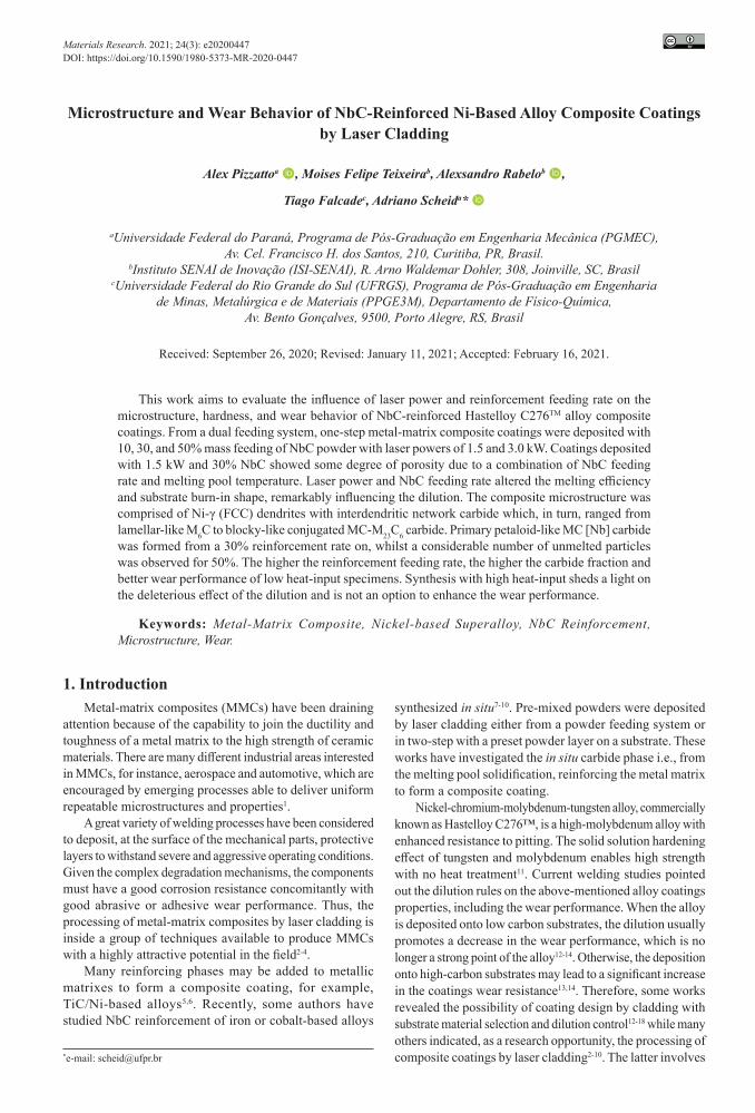
Figure 4 presents the macrographic analysis of the Hastelloy C276™ alloy and composite coatings. Only the specimens deposited adopting 1.5 kW laser power and 30% NbC feeding rate showed some degree of porosity.
Table 3 presents the single-bead geometry based on the cross-section images. The bead width showed a clear dependence on the laser power with higher values for 3.0 kW laser power. Initially, no obvious trend between the NbC feeding rate or laser power on the wettability angle and clad height was observed.
Figure 1. Typical feeding materials: Hastelloy C276™ alloy (a) and Niobium Carbide (b).
Figure 2. Typical X-ray patterns of NbC feeding powder.
Pizzatto et al.4 Materials Research
3.2. Microstructural evaluationFigure 6 and Figure 7 show the typical diffraction pattern
obtained for the composite coatings. Those deposited with 1.5 kW presented Ni-γ (FCC) solid solution and different carbide formation: MC [M: Nb, Mo], M6C [M: Fe, W, Mo], and M23C6 [M: Cr, Ni, Fe, Mo, W]. Furthermost, processing with higher heat-input (3.0 kW) led to the same phases excepting the M6C [M: Fe, W, Mo] carbide.
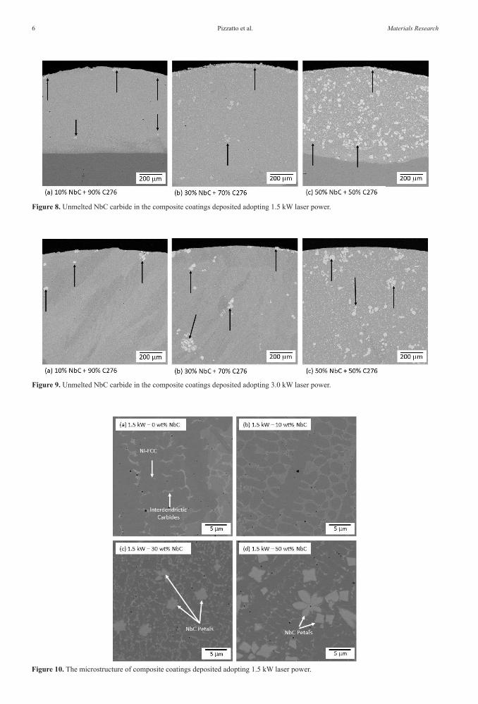
The microstructure was also evaluated from low to high magnification SEM images in the transverse cross-section of composite coatings. Even for the lower amount of NbC added (10%), some NbC particles are not properly molten, as indicated by the arrows in the images, and the amount increases for higher feeding rates, reaching the most uniform distribution for 50% NbC, as shown in Figure 8 and Figure 9. Also, a certain quantity is accumulated on the top surface of coatings.
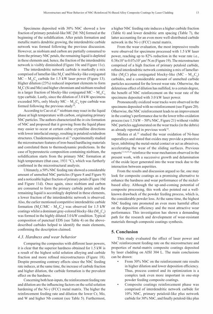
Besides the presence of unmelted NbC particles, it seems interesting now to evaluate the carbides formed from solidification, as shown in Figure 10 and Figure 11. Specimens reinforced with 10% NbC (Figure 10b and Figure 11b) showed Ni-γ (FCC) dendrites and interdendritic network carbides. Regardless of the laser power, from 30% NbC on (Figure 10c and d and Figure 11c and d), composite coatings showed primary petaloid-like MC [M: Nb] carbide formed from the liquid. After NbC petals formation and metallic matrix dendritic growing, the interdendritic network carbide was formed.
Afterward, from high-resolution FEG-SEM images, it is possible to better describe the interdendritic network
Figure 3. Schematic view of the single-bead: (a) as-deposited and (b) machined and evaluated top surface.
Figure 4. As deposited single-bead macrography of the coatings.
Table 3. Average bead geometry: wettability angle (Θ), bead width (BW), and clad height (t).
Laser Power (kW)
NbC Feeding Rate (%) Θ (°) BW
(mm) t (mm)
1.5
0 35 3.6 0.60
10 32 3.7 0.75
30 50 3.3 0.85
50 32 3.5 0.50
3.0
0 32 4.4 0.70
10 39 4.3 0.90
30 33 4.2 0.80
50 20 4.8 0.60
Figure 5 shows the distribution of the dilution and deposition efficiency versus laser power and feeding rate where it is possible to observe greater dilution when higher laser power is adopted. Regardless of the laser power, a 10% NbC feeding rate leads to a lower dilution, and from 30% NbC on, higher dilution is observed. On the one hand, the highest efficiency observed for 10% NbC led to higher deposited volume with a constant molten substrate, reducing the dilution. However, at a higher feeding rate, not only the reinforcement volume was reduced – due to efficiency decrease – but also the molten substrate was significantly increased, leading to increasing dilution.

5Microstructure and Wear Behavior of NbC-Reinforced Ni-Based Alloy Composite Coatings by Laser Cladding
Figure 5. Average deposition efficiency and dilution.
Figure 6. Typical X-ray diffraction pattern of composite coatings deposited applying 1.5 kW laser power.
Figure 7. Typical X-ray diffraction pattern of composite coatings deposited adopting 3.0 kW laser power.
Pizzatto et al.6 Materials Research
Figure 10. The microstructure of composite coatings deposited adopting 1.5 kW laser power.
Figure 8. Unmelted NbC carbide in the composite coatings deposited adopting 1.5 kW laser power.
Figure 9. Unmelted NbC carbide in the composite coatings deposited adopting 3.0 kW laser power.

7Microstructure and Wear Behavior of NbC-Reinforced Ni-Based Alloy Composite Coatings by Laser Cladding
carbide, as can be seen in Figure 12 to Figure 17. On the one hand, processing with 1.5 kW and 10% NbC led to a prominent M6C lamellar-like interdendritic network carbide, also containing a blocky-like conjugated MC - M23C6 type (see Figure 12a and b).
From the 30% NbC feeding rate on, the fraction of blocky-like carbides increases as the feeding rate increases, as seen in Figure 13 and Figure 14.
Finally, coatings deposited with 3.0 kW laser power showed no M6C lamellar-like carbides and the analysis evolves basically with the blocky-like conjugated MC – M23C6 type as can be seen in Figure 15, Figure 16, and Figure 17.
Table 4 shows the typical composition of the above-described carbides, obtained by EDS punctual analysis. It is promptly seen that the unmelted carbide particles and the primary petaloid-like formed from solidification contain mainly niobium and carbon. Taking into account the interdendritic network carbides, MC carbide shows slightly higher molybdenum and carbon whilst M6C presents also silicon in its composition. Ultimately, the composition of M23C6 carbide encompasses higher chromium, iron, nickel, and molybdenum.
Considering the phase differences, the evaluation of the strengthening mechanisms seems to bring an interesting baseline on the properties and performance of composite coatings. Solid solution alloying was evaluated from EDS analysis (Table 5), carbide fraction (Table 6), and refinement degree (Table 7) were analyzed as follows. The higher the reinforcement feeding rate and laser power, the lower Mo, and W and higher Nb content. Chromium was not pronouncedly affected because of the substrate chromium content.
Generally, a higher NbC feeding rate induces a higher carbide fraction, independently from the laser power adopted.
Besides, the higher the feeding rate the lower the dendritic arm spacing.
3.3. Hardness and wear behaviorHigher hardness and lower wear rate were observed for
composite coatings deposited with lower heat-input and higher NbC feeding rate, as shown in Figure 18 and Figure 19.
The evaluation of the wear tracks indicated the presence of darkened regions characterized as surface oxidation in the specimens deposited with no reinforcement, as shown in Figure 20. Also, the intensity of oxide formation seems to be reduced with the NbC addition, as seen in Figure 21.
4. Discussion
4.1. Bead geometry, dilution, and deposition efficiency
Considering welding defects, the coatings deposited with 1.5 kW laser power and 30% NbC showed some degree of porosity (see Figure 4). According to Li et al.8, pores may be formed by the engulfed gas during powder feeding and rapid solidification. Beyond the carrying gas, one maybe not be discarded here the possibility of gas evolution (CO/CO2) due to the reaction between carbon and oxygen from feeding material and, thus, the NbC addition is a potential source of gas. Moreover, a higher burn-in shape was observed for higher NbC feeding rates, altering notably the melting pool temperature and, therefore, the gas trapping tendency. Hence, especially for 1.5 kW with 30% NbC, the increased feeding rate (30% NbC) together with the rapid solidification probably led to a higher amount of porosity. Otherwise, for 10 and 50% NbC, porosity was not observed because of
Figure 11. The microstructure of composite coatings deposited adopting 3.0 kW laser power.

Pizzatto et al.8 Materials Research
Figure 12. Interdendritic carbides formed in the coatings deposited with 1.5 kW laser power and 10% NbC feeding rate.
Figure 13. Interdendritic carbides formed in the coatings deposited with 1.5 kW laser power and 30% NbC feeding rate.
Figure 14. Interdendritic carbides formed in the coatings deposited with 1.5 kW laser power and 50% NbC feeding rate.
Figure 15. Interdendritic carbides formed in the coatings deposited applying 3.0 kW laser power and 10% NbC feeding rate.

9Microstructure and Wear Behavior of NbC-Reinforced Ni-Based Alloy Composite Coatings by Laser Cladding
Figure 16. Interdendritic carbides formed in the coatings deposited with 3.0 kW laser power and 30% NbC feeding rate.
Figure 17. Interdendritic carbides formed in the coatings deposited with 3.0 kW laser power and 50% NbC feeding rate.
Table 4. Typical EDS punctual analysis of the carbides formed.
Laser power (kW) Punctual Region
Chemical Composition (Wt%)Ni Cr Fe Mo W Nb C Si
1.5
Unmelted NbC --- --- --- --- --- 84.4 15.6 ---PPC Bal. 7.1 3.7 6.7 0.8 68.0 10.9 ---
INC – M6C Bal. 16.4 3.8 25.4 4.7 2.2 6.9 1.6INC – MC Bal. 16.1 3.4 30.0 4.5 3.0 8.0 ---
INC – M23C6 Bal. 25.5 32.0 12.5 2.8 1.1 7.0 ---
3.0
Unmelted NbC --- --- --- --- --- 84.8 15.2 ---PPC Bal. 1.6 1.5 5.4 1.1 76.9 13.9 ---
INC – MC Bal. 22.6 20.7 24.8 4.3 1.6 11.4 ---INC – M23C6 Bal. 27.6 34.0 15.3 2.6 1.9 6.5 ---
PPC - Primary Petaloid Carbide, INC - M6C: Lamellar-like Interdendritic Network Carbide, INC - MC: White-Blocky Interdendritic Network Carbide, INC - M23C6: Gray-Blocky Interdendritic Network Carbide
Table 5. Typical EDS measurements in a 0.25 mm2 area.
kW NbC (%)Chemical Composition – Wt%
Ni Cr Fe Mo W Nb
1.5
0 Bal. 15.4 8.6 16.0 4.9 0.010 Bal. 15.1 5.7 15.6 5.1 1.130 Bal. 13.6 17.8 10.6 3.6 18.150 Bal. 15.0 34.0 6.4 2.2 16.1
3.0
0 Bal. 17.2 41.8 7.7 2.4 0.010 Bal. 15.5 31.5 10.0 3.2 1.430 Bal. 14.9 35.3 6.4 2.6 10.050 Bal. 14.1 41.0 4.2 1.4 21.1

Pizzatto et al.10 Materials Research
Table 6. Average carbide fraction of the composite coatings with the corresponding standard deviation of 5 measurements.
kW Carbide TypeReinforcement Feeding Rate
0% NbC 10% NbC 30% NbC 50% NbC
1.5From Solidification 5.5 ± 0.4 11.7 ± 0.4 15.5 ± 0.9 16.5± 0.6Unmelted NbC --- 0.7 ± 0.3 1.6 ± 0.2 6.7± 0.3Total 5.5 ± 0.4 12.4 ± 0.7 17.1 ± 1.1 23.2 ± 0.9
3.0From Solidification 1.8 ± 0.2 7.0 ± 0.5 9.1 ± 0.6 14.1± 1.0Unmelted NbC --- 0.5 ± 0.1 1.7 ± 0.2 5.4 ± 0.3Total 1.8 ± 0.2 7.5 ± 0.6 10.8 ± 0.8 19.5 ± 1.3
Table 7. Average dendritic arm spacing (DAS) of the composite coatings with the corresponding standard deviation of 50 measurements.
kW Refinement Parameter
Reinforcement Feeding Rate0% NbC 10% NbC 30% NbC 50% NbC
1.5 DAS 3.8 ± 1.0 2.4 ± 0.5 1.8 ± 0.3 1.5 ± 0.23.0 DAS 4.3 ± 0.5 3.5 ± 0.6 2.3 ± 0.8 2.2 ± 1.3
Figure 18. The hardness of composite coatings versus laser power and NbC feeding rate.
Figure 19. Wear rate of the composite coatings versus laser power and NbC feeding rate.

11Microstructure and Wear Behavior of NbC-Reinforced Ni-Based Alloy Composite Coatings by Laser Cladding
either lower feeding rate or higher melting pool temperature which hindered the gas holding.
For the geometry (see Table 3), the bead width presented higher values for 3.0 kW and, since the laser power is increased, the bead width gets close to the nominal value of laser spot size, following the previous work14. Also, a higher clad height was observed for higher deposition efficiency
(furtherly discussed in this section) following, with good confidence, the coatings molten volume, corroborating with the previous report22. However, no clear correlation between the NbC feeding rate or laser power and wettability angle was verified. Initially, it seems that the alloying of the metallic matrix with NbC induced a variable liquid surface tension of the composite coatings, resulting in an unpredictable
Figure 20. Wear track of the non-reinforced coating deposited with 1.5 kW. Magnification increases from (a) to (d).
Figure 21. Wear track of the coating deposited with 1.5 kW and a 50% NbC feeding rate. Magnification increases from (a) to (d).

Pizzatto et al.12 Materials Research
wettability. However, at least three factors must be considered: the reinforcement feeding rate, deposition efficiency, and also dilution with the substrate.
Ibrahim, Mohamed, and Lavernia30 presented a review about particulate reinforced metal-matrix composites and pointed out that wettability may be measured through the solid-liquid contact angle (θ). The driving force for wetting depends on the solid-liquid interface energy and liquid surface tension, being influenced by many factors. At this rate, the discussion about dilution and deposition efficiency may shed a light on the above-mentioned intricate analysis.
Under the influence of the Gaussian laser energy distribution14,19,20, processing with 1.5 kW indicated a shallower molten substrate area with the most uniform burn-in shape (Figure 4). Thus, a higher dilution was measured for composite coatings deposited with high heat-input (3.0 kW), although a noteworthy increase was also identified as higher than 30% NbC is added (Figure 5). Yaowei et al.31 reported that reactions with a high exothermic value of enthalpy along with the composite synthesis (conversion of oxide to carbide phase) contributed to a high dilution with the substrate. In the present study, the thermodynamic data32 showed niobium oxide (Nb2O5) has lower Gibbs free energy when compared with niobium carbide (NbC) and the expected conversion with the heat release should not occur.
Facing the variable powder mixtures and solidification process, it is reasonable to consider, at least, two different reasons for the above-mentioned effect of the NbC feeding rate on the dilution. From 30% NbC on, the heat transfer from the laser beam to the high melting point NbC powder particles induced an increase in the melting pool temperature, notably evidenced by the larger burn-in shape (Figure 4). Also, it is plausible to suggest that the heat released from the solidification of the highly exothermic NbC primary phase may also have extended the time of the liquid phase.
Furthermore, the present investigation revealed the unmistakable influence of laser power (or heat-input) on the deposition efficiency which, in turn, was higher for 3.0 kW (Figure 5). Otherwise, when the NbC feeding rate is concerned, 10 and 30% NbC induced a slight increase in deposition efficiency. At 50% NbC it seems that the high melting point and the limited plasticity of the ceramic phase induced a more pronounced powder rebounding, lowering the efficiency.
Previous works22,23,28 have reported that efficiency is a drawback in powder feed laser cladding. It is related to the laser process parameters like laser power, powder feeding rate, feeding angle, travel speed, and so on. According to Lee28, for optimum deposition efficiency, the powder must stay in the laser beam as long as possible to be heated up and to became plastic when getting contact with the substrate surface. After that, the powder and substrate may be molten together with diminished rebounding.
From the discussion, understanding the complexity of the melting pool chemical composition is clearer. The unpredictable percentual of NbC added to the metal-matrix itself – due to the changeable deposition efficiency – and the distinct dilution with the substrate – altered concomitantly by the laser power and reinforcement feeding rate – helped to reveal how difficult is the task of bead geometry analysis in the synthesis of composite coatings.
4.2. Microstructural evaluationConcerning the previous works12-14, the second phases
formed in the Hastelloy C276™ alloy deposited on the low conductivity stainless steel are expected, in this case, mainly gray blocky-like M23C6 [M: Cr] and white blocky-like MC [M: Mo] and, under certain conditions, also lamellar-like M6C [M: Fe, Mo, W] carbide. Otherwise, the different percentual of NbC added and the dilution trends reported in the previous section are rather important factors that govern the phase formation.
Shin et al.25 evaluated different carbide types in Co-based superalloy (M6C, M23C6, and others). The authors mentioned how intricate may be the phase identification through XRD analysis, basically due to the wide solubility of most carbide which, in turn, leads to variable lattice parameters. In this context, Wieczerzak, et al.26 investigated the carbide formation in Fe-Cr-Mo-C alloy and reported that, in M23C6 [M: Cr] carbide, Cr sites can be replaced by Fe and Mo.
In this work, the diffraction pattern of composite coatings deposited with 1.5 kW (Figure 6) showed Ni-γ (FCC) solid solution and different carbides: MC [M: Nb, Mo], M6C [M: Fe, W, Mo] and M23C6 [M: Cr, Ni, Fe, Mo, W]. Excepting M6C [M: Fe, W, Mo] carbide, the same phases were noticed in 3.0 kW specimens (Figure 7). The metallic elements replaced each other in the carbide formulae, following the above-referred authors25,26.
Regardless of the laser power, SEM evaluation revealed prevalent interdendritic network carbide for 10% NbC, interdendritic plus a low fraction of primary petals for 30% NbC, and, finally, interdendritic with a considerable amount of both primary petaloid-like and unmelted carbide for 50% NbC. Thus, further discussion evolves dealing with the microstructure formation and its features.
From 10% NbC specimens, a noticeably higher fraction of interdendritic network carbide was observed in comparison to the non-reinforced alloy (Figure 10b and Figure 11b). As the columnar dendritic solidification starts from the Ni-γ (FCC) metallic matrix, the carbide formers (Mo, W, and Nb) and carbon accumulate in interdendritic areas leading to the carbide network.
The detailed investigation of the carbide morphology showed that lamellar-like M6C was the main carbide in 10% NbC/1.5 kW specimens (Figure 12). The low dilution avoided the decrease in silicon and molybdenum content and the low heat-input led to a higher solidification cooling rate which hindered the segregation of carbon and molybdenum and dictated the M6C formation. The opposing effect was verified for 3.0 kW specimens, that is, the highest heat-input and dilution (> 40%) induced only blocky-like conjugated MC - M23C6 carbide (Figure 15). Therefore, the results pointed out the rule of heat-input and dilution on the interdendritic carbide type and morphology. Jiang et al.24 investigated the competitive formation of M2C and M6C in Ni-Mo-Cr superalloy and reported that silicon induces a reduction in the Gibbs free energy of M6C carbide and can inhibit the M2C formation in as-cast microstructures. The authors also have argued that the formation of M2C needs more severe segregation to provide enough Mo and C when compared to M6C carbide.
13Microstructure and Wear Behavior of NbC-Reinforced Ni-Based Alloy Composite Coatings by Laser Cladding
Specimens deposited with 30% NbC showed a low fraction of primary petaloid-like MC [M: Nb] formed at the beginning of the solidification. After petals formation and metallic matrix dendritic growing, the interdendritic carbide network was formed following the previous discussion. However, as niobium and carbon are partially consumed to form the primary NbC petals, the remaining liquid is depleted in these elements and, hence, the fraction of the interdendritic network is visibly diminished (Figure 10c and Figure 11c).
The interdendritic network carbide is markedly a mix comprised of lamellar-like M6C and blocky-like conjugated MC – M23C6 carbide for 1.5 kW laser power (Figure 13). Higher dilution (23%) reduced important elements to form M6C (Si and Mo) and higher chromium and niobium resulted in a larger fraction of blocky-like conjugated MC – M23C6 type carbide. Lastly, since the dilution of 3.0 kW specimens exceeded 50%, only blocky MC – M23C6 type carbide was formed following the previous study24.
According to Cao et al.27 niobium may react in the liquid phase at high temperature with carbon, originating primary NbC particles. The authors characterized the in situ formation of NbC and proposed that it growing from the liquid phase may easier to occur at certain cubic crystalline directions with lower interfacial energy, resulting in petaloid octahedron structures. Chaidemenopoulos et al.33 experimentally studied the microstructure features of iron-based hardfacing materials and correlated them to thermodynamic predictions. In the case of hypereutectic composition containing niobium, the solidification starts from the primary NbC formation at high temperature (that case, 1931 °C), which was furtherly confirmed in the microstructural analysis.
Ultimately, a 50% NbC feeding rate showed a considerable amount of unmelted NbC particles (Figure 8 and Figure 9) and a noticeable higher fraction of primary petals (Figure 10d and Figure 11d). Once again, since niobium and carbon are consumed to form the primary carbide petals and the remaining liquid is accordingly depleted in these elements, a lower fraction of the interdendritic network is observed. Also, the earlier mentioned competitive interdendritic carbide formation (M6C/MC - M23C6) was observed for 1.5 kW coatings whilst a dominant gray-colored blocky-like (M23C6) was formed in the highly diluted 3.0 kW condition. Typical composition of punctual EDS (see Table 4) on the above-described carbides helped to identify the main elements, confirming the description claimed.
4.3. Hardness and wear behaviorComparing the composites with different laser powers,
it is clear that the superior hardness obtained for 1.5 kW is a result of the highest solid solution alloying and carbide fraction and more refined microstructures (Figure 18). Despite presenting contrary effects since the NbC feeding rate induces, at the same time, the increase of carbide fraction and higher dilution, the carbide formation is the prevalent effect on the hardness.
Concerning both heat-inputs, the reinforcement feeding rate and dilution are the influencing factors on the solid solution hardening of the Ni-γ (FCC) metal matrix. The higher the reinforcement feeding rate and dilution the lower Cr, Mo, and W and higher Nb content (see Table 5). Furthermost,
a higher NbC feeding rate induces a higher carbide fraction (Table 6) and lower dendritic arm spacing (Table 7), the latter accounting for an even more well-distributed carbide network in the Ni-γ (FCC) metal matrix.
From the wear evaluation, the most impressive results were observed for specimens processed with 1.5 kW laser power, reaching up to 82% reduction in the wear rate i.e., 0.38x10⁵ to 0.07x105 μm3/N.m (Figure 19). The microstructure comprised of a high fraction of primary petaloid carbide, refined interdendritic network containing a mix of lamellar-like (M6C) plus conjugated blocky-like (MC - M23C6) carbides, and a considerable amount of unmelted carbide particles accounted for the lowest wear rate. Otherwise, the deleterious effect of dilution has nullified, to a certain degree, the benefit of NbC reinforcement on the wear rate of the specimens deposited with 3.0 kW laser power.
Pronouncedly oxidized wear tracks were observed in the specimens deposited with no reinforcement (see Figure 20). Otherwise, the NbC reinforcement leads to an improvement in the coating’s performance due to the lower tribo-oxidation process (see 1.5 kW – 50% NbC, Figure 21) without visible NbC particles agglomerated on the wear tracks (in the debris) as already reported in previous work34.
Mishra et al.35 studied the wear oxidation of Ni-base superalloys and stated that oxides may provide a protective layer, inhibiting the metal-metal contact or act as abrasives, accelerating the wear of the sliding surfaces. Previous reports13,14,35,36 reinforce the wear mechanism observed in the present work, with a successive growth and delamination of the oxide layer generated into the wear track due to the interaction between asperities.
From the results and discussion argued so far, one may look for composite coatings as a promising alternative to enhance the hardness and wear performance of the nickel-based alloy. Although the up-and-coming potential of composite processing, this work also pointed out a well-known drawback of the powder feeding process, which is, the considerable powder loss. At the same time, the highest NbC feeding rate promoted an even more harmful effect on the deposition efficiency and the most attractive wear performance. This investigation has shown a demanding path for the research and development of wear-resistant materials through composite coatings synthesis.
5. ConclusionThis study evaluated the effect of laser power and
NbC reinforcement feeding rate on the microstructure and properties of metal-matrix composite coatings deposited by laser cladding on AISI 304 L. The main conclusions can be drawn:
• From 30% NbC on the reinforcement rate results in higher dilution and lower deposition efficiency. Thus, process control and its optimization is a complex task even more important in one-step powder feeding composite coatings.
• Composite coatings reinforcement phase was comprised of interdendritic network carbide for 10% NbC, primary petaloid-like plus network carbide for 30% NbC, and finally petaloid-like plus

Pizzatto et al.14 Materials Research
network carbide still containing unmelted particles for 50% NbC.
• The reinforcement feeding rate of 10% led to a higher fraction of the interdendritic network carbide. At higher rates, a gradual replacement of the interdendritic network by petaloid-like primary carbide ruled the formation of the phases from solidification.
• The composite carbide fraction did not encompass exactly the powder feed rate, due to the variable melting efficiency and dilution. However, a higher NbC feeding rate resulted in a higher carbide fraction and hardness than the non-reinforced alloy.
• The wear rate of coatings deposited with 1.5 kW laser power confirmed the expected benefit due to NbC addition, in this case, showing a wear performance up to 82% superior. The present study emphasized how attractive is to research the possibilities of superalloy reinforcement as metal-matrix composite coatings.
6. AcknowledgmentsThe authors thank SENAI Institute for Innovation (ISI
Joinville) for the support of laser processing and characterization.
7. References1. Chou TW, Kelly A, Okura A. Fibre-reinforced metal-matrix
composites. Composites. 1985;16:187-206.2. Man HC, Zhang S, Cheng FT, Yue TM. Microstructure and
formation mechanism of in situ synthesized TiC/Ti surface MMC on Ti-6Al-4V by laser cladding. Scr Mater. 2001;44:2801-7. http://dx.doi.org/10.1016/S1359-6462(01)00977-0.
3. Emamian A, Corbin SF, Khajepour A. Effect of laser cladding process parameters on clad quality and in-situ formed microstructure of Fe–TiC composite coatings. Surf Coat Tech. 2010;205:2007-15. http://dx.doi.org/10.1016/j.surfcoat.2010.08.087.
4. Wang X, Zhang M, Qu S. Development and characterization of (Ti, Mo) C carbides reinforced Fe-based surface composite coating produced by laser cladding. Opt Lasers Eng. 2010;48:893-8. http://dx.doi.org/10.1016/j.optlaseng.2010.03.017.
5. Yang S, Zhong M, Liu W. TiC particulate composite coating produced in situ by laser cladding. Mater Sci Eng A. 2003;343:57-62. http://dx.doi.org/10.1016/S0921-5093(02)00361-1.
6. Li Q, Lei TC, Chen WZ. Microstructural characterization of laser-clad Ti Cp-reinforced Ni-Cr-B-Si-C composite coatings on steel. Surf Coat Tech. 1999;114:278-84. http://dx.doi.org/10.1016/S0257-8972(99)00055-9.
7. Cao Y, Ren H, Hu R, Meng Q, Liu Q. In-situ formation behavior of NbC-reinforced Fe-based laser cladding coatings. Mater Lett. 2015;147:61-3. http://dx.doi.org/10.1016/j.matlet.2015.02.026.
8. Li Q, Lei Y, Fu H. Laser cladding in-situ NbC particle reinforced Fe-based composite coatings with rare earth oxide addition. Surf Coat Tech. 2014;239:102-7. http://dx.doi.org/10.1016/j.surfcoat.2013.11.026.
9. Sun S, Fu H, Ping X, Lin J, Lei Y, Wu W, et al. Reinforcing behavior and microstructure evolution of Nb C in laser cladded Ni45 coating. Appl Surf Sci. 2018;455:160-70. http://dx.doi.org/10.1016/j.apsusc.2018.05.199.
10. Chen Z, Yan H, Zhang P, Yu Z, Lu Q, Guo J. Microstructural evolution and wear behaviors of laser-clad Stellite 6/NbC/h-BN self-lubricating coatings. Surf Coat Tech. 2019;372:218-28. http://dx.doi.org/10.1016/j.surfcoat.2019.04.083.
11. Mankins WL, Lamb S. Nickel and nickel alloys. In: ASM International. Properties and selection: nonferrous alloys and special-purposed materials. Ohio: Materials Park; 1990. p. 1363-403.
12. Ferreira LS, Graf K, Scheid A. Microstructure and properties of Nickel-based C276 Alloy Coatings by PTA on AISI 316L and API 5L X70 steel substrates. Mater Res. 2015;18:212-21. http://dx.doi.org/10.1590/1516-1439.332914.
13. Rivero LEHS. Avaliação de revestimentos de superliga Hastelloy® C276 depositados a laser sobre diferentes substratos [dissertação]. Curitiba: Universidade Federal do Paraná; 2019 [cited 2018 Mar 20]. Available from: www.prppg.ufpr.br/pgmec/wp-content/uploads/2020/01/lubar.pdf
14. Rivero LEHS, Pizzatto A, Teixeira MF, Rabelo A, Falcade T, Scheid A. Effect of laser power and substrate on the hastelloy C276TM coatings features deposited by laser cladding. Mater Res. 2020;25:1-11. http://dx.doi.org/10.1590/1980-5373-MR-2020-0067.
15. Fernandes F, Cavaleiro A, Loureiro A. Oxidation behavior of Ni-based coatings deposited by PTA on gray cast iron. Surf Coat Tech. 2012;207:96-203. http://dx.doi.org/10.1016/j.surfcoat.2012.06.070.
16. Graf K, Tetzlaff U, Souza GB, Scheid A. Effect of dilution on the microstructure and properties of CoCrMoSi alloy coatings processed on high-carbon substrate. Mater Res. 2019;22:1-7. http://dx.doi.org/10.1590/1980-5373-MR-2018-0502.
17. Antoszczyszyn TJ, Paes RMG, Oliveira ASCM, Scheid A. Impact of dilution on the microstructure and properties of Ni-based 625 alloy coatings. Soldag Insp. 2014;19:134-44. http://dx.doi.org/10.1590/0104-9224/SI1902.05.
18. Paes RMG, Martinazzi D, Falcade T, Scheid A. Effect of bead overlapping on the microstructure and mechanical properties of CoCrWC alloy coatings. Mater Res. 2018;21:1-7. http://dx.doi.org/10.1590/1980-5373-MR-2018-0274.
19. Toyserkani E, Khajepour A, Corbin S. Laser cladding. Washington: CRC Press; 2005. p. 179-224.
20. Goodarzi DM, Pekkarinen J, Salminen A. Effect of process parameters in laser cladding on substrate melted areas and the substrate melted shape. J Laser Appl. 2015;27:1-9. http://dx.doi.org/10.2351/1.4906376.
21. Zhong M, Liu W. Laser surface cladding: the state of the art and challenges. Proceedings of the Institution of Mechanical Engineers, Part C: Journal of Mechanical Engineering Science. 2010;224(5):1-20. http://dx.doi.org/10.1243/09544062JMES1782.
22. Haldar B, Saha P. Identifying defects and problems in laser cladding and suggestions of some remedies for the same. Mater. Today Proc. 2018;5:13090-101. http://dx.doi.org/10.1016/j.matpr.2018.02.297.
23. Mahamood RM. Laser metal deposition process of metals, alloy, and composite materials, Switzerland: Springer International Publishing; 2018.
24. Jiang L, Zhang W, Xu Z, Huang H, Ye X, Leng B, et al. 2C and M6C carbide precipitation in Ni-Mo-Cr based superalloys containing silicon. Mater Des. 2016;112:300-8. http://dx.doi.org/10.1016/j.matdes.2016.09.075.
25. Shin J, Doh J, Yoon J, Lee D, Kim J. Effect of molybdenum on the microstructure and wear resistance of cobalt-base Stellite hardfacing alloys. Surf Coat Tech. 2003;166:117-26. http://dx.doi.org/10.1016/S0257-8972(02)00853-8.
26. Wieczerzak K, Bala P, Stepien M, Cios G, Koziel T. Formation of eutectic carbides in Fe–Cr–Mo–C alloy during non-equilibrium crystallization. Mater Des. 2016;94:61-8. http://dx.doi.org/10.1016/j.matdes.2016.01.028.
27. Cao Y, Zhi S, Gao Q, Tian X, Geng T, Guan X, et al. Formation behavior of in-situ NbC in Fe-based laser cladding coatings. Mater Charact. 2016;119:159-65. http://dx.doi.org/10.1016/j.matchar.2016.08.005.
28. Lee H. Effects of the cladding parameters on the deposition efficiency in pulsed Nd: YAG laser cladding. J Mater Process

15Microstructure and Wear Behavior of NbC-Reinforced Ni-Based Alloy Composite Coatings by Laser Cladding
Technol. 2008;202:321-7. http://dx.doi.org/10.1016/j.jmatprotec.2007.09.024.
29. Rasband WS. Image J [Internet]. Bethesda: U. S. National Institutes of Health; 1997-2015 [cited 2018 Mar 20]. Available from: http://imagej.nih.gov/ij/
30. Ibrahim IA, Mohamed FA, Lavernia EJ. Particulate reinforced metal matrix composites – a review. J Mater Sci. 1991;26:1137-1156. http://dx.doi.org/10.1007/BF00544448.
31. Yaowei Y, Wei F, Xiang Z, Qilin D, Jianguo Y. In-situ synthesis of WC/TaC reinforced Nickel-based composite alloy coating by laser cladding. Rare Met Mater Eng. 2017;46:3176-81. http://dx.doi.org/10.1016/S1875-5372(18)30024-9.
32. Barin I. Thermochemical Data of Pure Substances. Germany: Wiley-VCH Verlag GmbH; 1995. p. 1163-1175.
33. Chaidemenopoulos NG, Psyllaki PP, Pavlidou E, Vourlias G. Aspects on carbides transformations of Fe-based hardfacing deposits. Surf Coat Tech. 2019;357:651-61. http://dx.doi.org/10.1016/j.surfcoat.2018.10.061.
34. Woydt M, Mohrbacher H. Friction and wear of binder-less niobium carbide. Wear. 2013;306:126-30. http://dx.doi.org/10.1016/j.wear.2013.07.013.
35. Mishra SB, Chandra K, Prakash S. Dry sliding wear behavior of nickel-, iron- and cobalt-based superalloys. Tribology. 2013;7:122-8. http://dx.doi.org/10.1179/1751584X13Y.0000000038.
36. Navas C, Cadenas M, Cuetos JM, de Damborenea J. Microstructure and sliding wear behavior of Tribaloy T-800 coatings deposited by laser cladding. Wear. 2006;260:838-46. http://dx.doi.org/10.1016/j.wear.2005.04.020.


![MICROSTRUCTURE-BASED FINITE ELEMENT · PDF file3 MICROSTRUCTURE-BASED FINITE ELEMENT MODELING OF PARTICLE REINFORCED METAL MATRIX COMPOSITES extensively [20, 21].](https://static.fdocuments.in/doc/165x107/5a78bc737f8b9a83238bb5cc/microstructure-based-finite-element-microstructure-based-finite-element-modeling.jpg)