Microstrip Matching Networks Series- and Shunt-stub...
16
Indraprastha Institute of Information Technology Delhi ECE321/521 Lecture – 12 Date: 09.02.2017 • Microstrip Matching Networks • Series- and Shunt-stub Matching • Quarter Wave Impedance Transformer
Transcript of Microstrip Matching Networks Series- and Shunt-stub...
Indraprastha Institute of
Information Technology Delhi ECE321/521
Lecture – 12 Date: 09.02.2017
• Microstrip Matching Networks• Series- and Shunt-stub Matching • Quarter Wave Impedance Transformer
Indraprastha Institute of
Information Technology Delhi ECE321/521
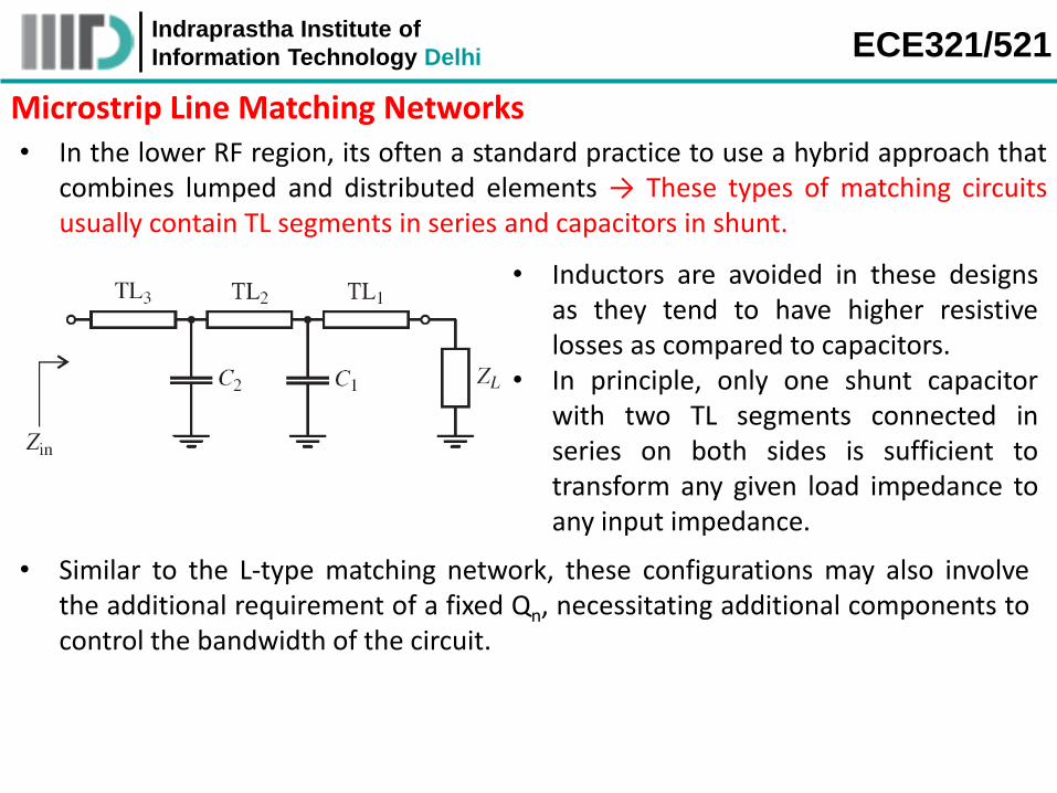
Microstrip Line Matching Networks • In the lower RF region, its often a standard practice to use a hybrid approach that
combines lumped and distributed elements → These types of matching circuitsusually contain TL segments in series and capacitors in shunt.
• Inductors are avoided in these designsas they tend to have higher resistivelosses as compared to capacitors.
• In principle, only one shunt capacitorwith two TL segments connected inseries on both sides is sufficient totransform any given load impedance toany input impedance.
• Similar to the L-type matching network, these configurations may also involvethe additional requirement of a fixed Qn, necessitating additional components tocontrol the bandwidth of the circuit.
Indraprastha Institute of
Information Technology Delhi ECE321/521
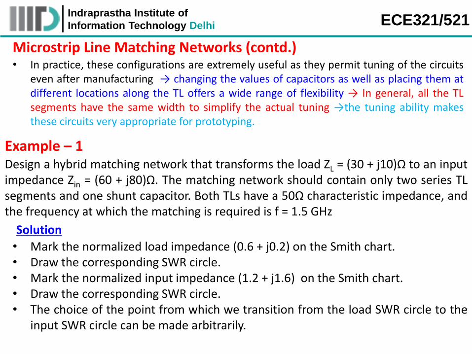
Microstrip Line Matching Networks (contd.) • In practice, these configurations are extremely useful as they permit tuning of the circuits
even after manufacturing → changing the values of capacitors as well as placing them atdifferent locations along the TL offers a wide range of flexibility → In general, all the TLsegments have the same width to simplify the actual tuning →the tuning ability makesthese circuits very appropriate for prototyping.
Example – 1 Design a hybrid matching network that transforms the load ZL = (30 + j10)Ω to an inputimpedance Zin = (60 + j80)Ω. The matching network should contain only two series TLsegments and one shunt capacitor. Both TLs have a 50Ω characteristic impedance, andthe frequency at which the matching is required is f = 1.5 GHz
Solution
• Mark the normalized load impedance (0.6 + j0.2) on the Smith chart.• Draw the corresponding SWR circle.• Mark the normalized input impedance (1.2 + j1.6) on the Smith chart.• Draw the corresponding SWR circle.• The choice of the point from which we transition from the load SWR circle to the
input SWR circle can be made arbitrarily.

Indraprastha Institute of
Information Technology Delhi ECE321/521
Example – 1 (contd.) Normalized load
to the point A gives length of
the first segment of TL
point B to normalized input impedance gives
length of the second segment
of TL
A to B provides the necessary susceptance value for the
shunt capacitor
Indraprastha Institute of
Information Technology Delhi ECE321/521
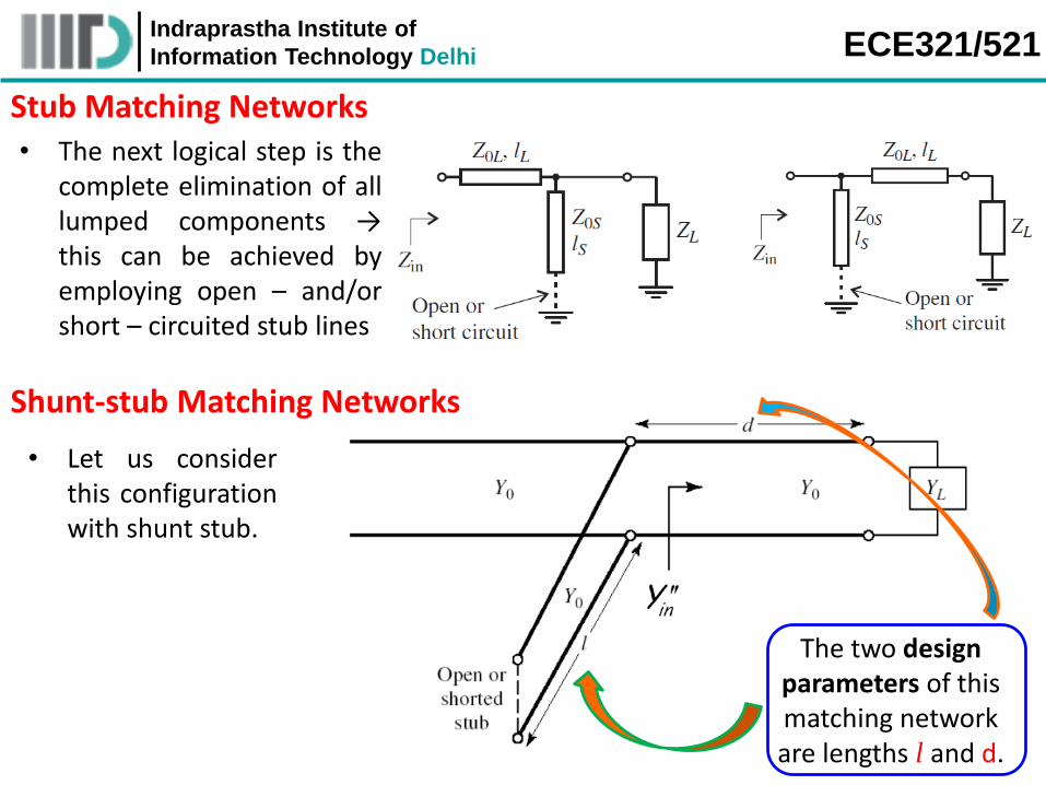
Stub Matching Networks • The next logical step is the
complete elimination of alllumped components →this can be achieved byemploying open – and/orshort – circuited stub lines
• Let us considerthis configurationwith shunt stub.
Shunt-stub Matching Networks
The two design parameters of this matching network are lengths l and d.
Indraprastha Institute of
Information Technology Delhi ECE321/521
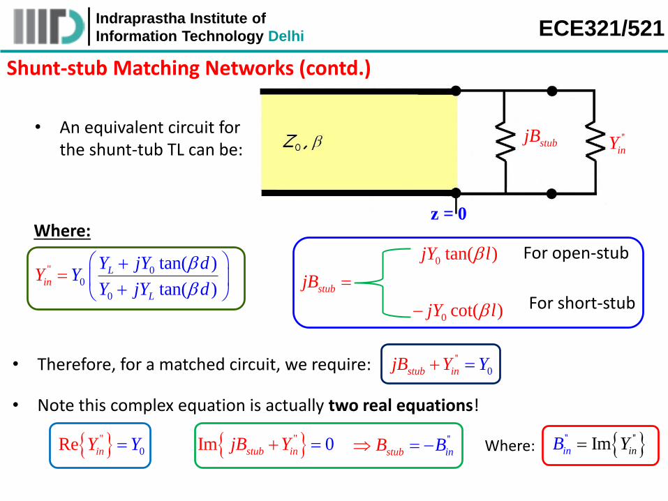
Shunt-stub Matching Networks (contd.)
• An equivalent circuit for the shunt-tub TL can be:
z = 0
stubjB ''
inY
Where:
00
0
" tan( )
tan( )
Lin
L
Y jY dY
Y jYY
d
stubjB
0 tan( )jY l
0 cot( )jY l
For open-stub
For short-stub
• Therefore, for a matched circuit, we require: 0
''
stub injB Y Y
• Note this complex equation is actually two real equations!
" 0Re inY Y "Im 0stub injB Y ''
stub inB B ' ''' Imi nn iB YWhere:
Indraprastha Institute of
Information Technology Delhi ECE321/521
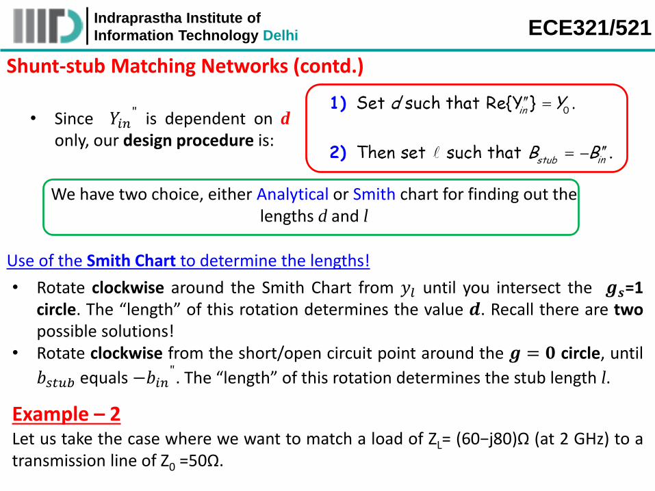
Shunt-stub Matching Networks (contd.)
• Since 𝑌𝑖𝑛" is dependent on d
only, our design procedure is:
We have two choice, either Analytical or Smith chart for finding out the lengths d and l
Use of the Smith Chart to determine the lengths!
• Rotate clockwise around the Smith Chart from 𝑦𝑙 until you intersect the 𝒈𝒔=1circle. The “length” of this rotation determines the value 𝒅. Recall there are twopossible solutions!
• Rotate clockwise from the short/open circuit point around the 𝒈 = 𝟎 circle, until
𝑏𝑠𝑡𝑢𝑏 equals −𝑏𝑖𝑛". The “length” of this rotation determines the stub length l.
Let us take the case where we want to match a load of ZL= (60−j80)Ω (at 2 GHz) to atransmission line of Z0 =50Ω.
Example – 2
Indraprastha Institute of
Information Technology Delhi ECE321/521
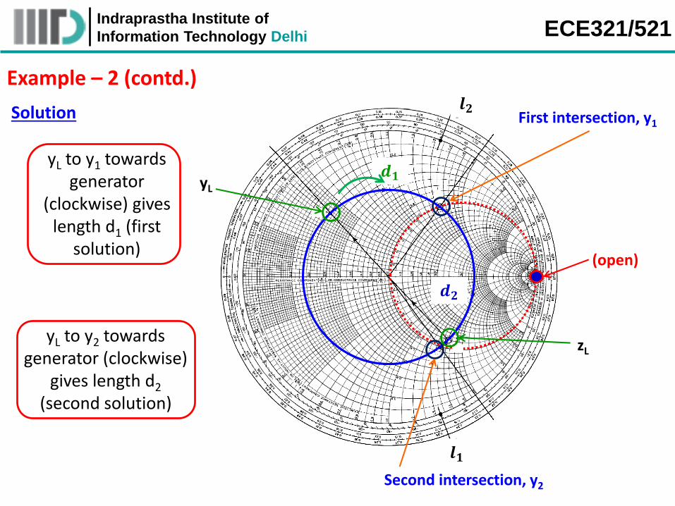
Example – 2 (contd.)
yL to y1 towards generator
(clockwise) gives length d1 (first
solution)
yL to y2 towards generator (clockwise)
gives length d2
(second solution)
Solution
zL
yL
First intersection, y1
Second intersection, y2
(open)
𝒅𝟏
𝒅𝟐
𝒍𝟏
𝒍𝟐
Indraprastha Institute of
Information Technology Delhi ECE321/521
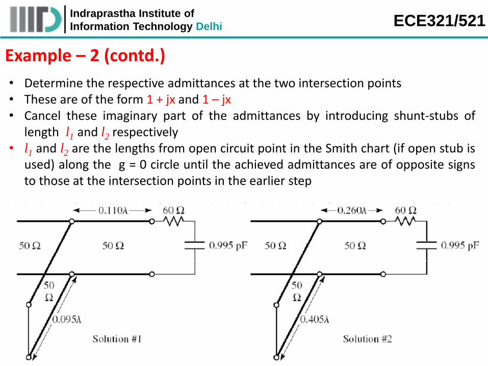
Example – 2 (contd.)
• Determine the respective admittances at the two intersection points• These are of the form 1 + jx and 1 – jx• Cancel these imaginary part of the admittances by introducing shunt-stubs of
length l1 and l2 respectively• l1 and l2 are the lengths from open circuit point in the Smith chart (if open stub is
used) along the g = 0 circle until the achieved admittances are of opposite signsto those at the intersection points in the earlier step

Indraprastha Institute of
Information Technology Delhi ECE321/521
Q: Two solutions! Which one do we use?
Example – 2 (contd.)
A: The one with the shortest lengths of transmission line!
Q: Oh, I see! Shorter transmission lines provide smaller and (slightly) cheapermatching networks.
A: True! But there is a more fundamental reason why we select the solution with theshortest lines—the matching bandwidth is larger!
• For example, consider the frequency response of the two solutions:
Clearly, solution 1 provides a wider
bandwidth!

Indraprastha Institute of
Information Technology Delhi ECE321/521
Series-stub Matching Networks • Consider the following transmission line structure, with a series stub:
where of course:
00
0
" tan( )
tan( )
Lin
L
Z jZ dZ
Z jZZ
d
stubjX
0 cot( )jZ l
0 tan( )jZ l
For open-stub
For short-stub
Therefore an equivalent circuit is:
stubjX''
inZ
Let us take the case where we want to match a load of ZL= (100 + j80)Ω (at 2 GHz) toa transmission line of Z0 =50Ω.
Example – 3
Indraprastha Institute of
Information Technology Delhi ECE321/521
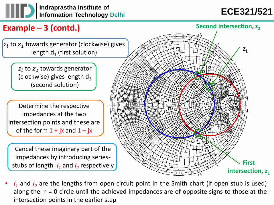
Example – 3 (contd.)
zL
First intersection, z1
Second intersection, z2
𝑧𝑙 to 𝑧1 towards generator (clockwise) gives length d1 (first solution)
𝑧𝑙 to 𝑧2 towards generator (clockwise) gives length d2
(second solution)
Determine the respective impedances at the two
intersection points and these are of the form 1 + jx and 1 – jx
Cancel these imaginary part of the impedances by introducing series-
stubs of length l1 and l2 respectively
• l1 and l2 are the lengths from open circuit point in the Smith chart (if open stub is used)along the r = 0 circle until the achieved impedances are of opposite signs to those at theintersection points in the earlier step

Indraprastha Institute of
Information Technology Delhi ECE321/521
Example – 3 (contd.)
Again, we should use the solution with the shortest transmission lines, although in this case that
distinction is a bit ambiguous. As a result, the bandwidth of each
design is about the same (depending on how you define
bandwidth!).

Indraprastha Institute of
Information Technology Delhi ECE321/521
Example – 4
For a load impedance of ZL= (60 – j45)Ω, design single-stub (shunt) matchingnetworks that transform the load to a Zin =(75 + j90)Ω input impedance. Assume boththe stub and transmission line have a characteristic impedance of Z0 = 75Ω
Solution
• Normalize the ZL and Zin with 75Ω• Mark these normalized impedances on the Z-Smith chart• Move to Y-Smith chart or better use ZY-Smith chart • Plot constant conductance (gL) circle• Plot SWR circle for normalized input impedance (zin) • Two intersection points between constant conductance circle and SWR circle can
be observed • Rotation from intersection points to zin give the lengths d1 and d2 and
corresponding changes in admittance • Look for cancelling the additional admittances using shunt stub by equating
corresponding stub lengths from ‘open’ in Smith chart
Indraprastha Institute of
Information Technology Delhi ECE321/521
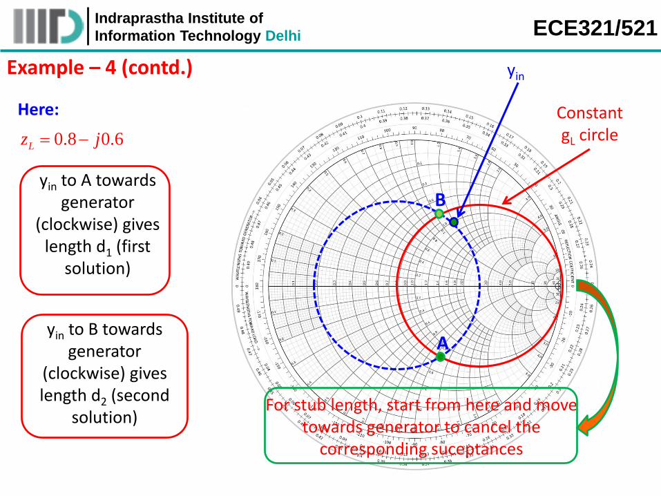
Example – 4 (contd.)
yin to A towards generator
(clockwise) gives length d1 (first
solution)
yin to B towards generator
(clockwise) gives length d2 (second
solution)
Constant gL circle
yin
0.8 0.6Lz j
Here:
For stub length, start from here and move towards generator to cancel the
corresponding suceptances
A
B
Indraprastha Institute of
Information Technology Delhi ECE321/521
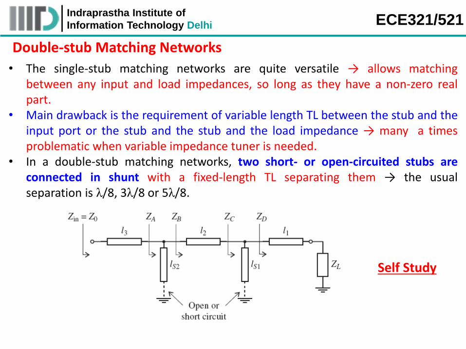
Double-stub Matching Networks
• The single-stub matching networks are quite versatile → allows matchingbetween any input and load impedances, so long as they have a non-zero realpart.
• Main drawback is the requirement of variable length TL between the stub and theinput port or the stub and the stub and the load impedance → many a timesproblematic when variable impedance tuner is needed.
• In a double-stub matching networks, two short- or open-circuited stubs areconnected in shunt with a fixed-length TL separating them → the usualseparation is λ/8, 3λ/8 or 5λ/8.
Self Study