Microsoft Word - Lateral2_2006_.doc · Web viewMicrosoft Word - Lateral2_2006_.doc Last modified...
50
©Copyright 2018 by Sanitary Management & Revision Date – 4/23/18 X:MSWorddocs\ 1 HAMILTON-SOUTHEASTERN UTILITIES, INC. __________________________________ STANDARDS FOR DESIGN AND CONSTRUCTION OF LATERALS 2018 The ideas, designs, drawings and concepts contained herein are the exclusive intellectual property of Sanitary Management & Engineering Company, Inc. and are not to be used or reproduced in whole or in part, without the written consent of Sanitary Management & Engineering Company, Inc. 1.1 GENERAL........................................................ 3 A. Definitions...........................................3 B. Purpose.............................................. 3 C. Applicability........................................4 D. Liability and Cost...................................4 E. Standards, Specifications and Details.................4 F. Drawing Discrepancies and Omissions...................4 G. Governing Laws, Codes and Regulations.................5 H. Notices.............................................. 5 I. Confined Space Entry.................................5 J. Maintenance.......................................... 5 K. Compliance............................................5 1.2 LATERALS....................................................... 5 A. Lateral Connection Permit.............................6 B. Prohibition against Clear Water Discharges............7 C. Notice of Violation..................................9 D. Mandatory Inspection of Building Connections..........9
-
Upload
nguyenminh -
Category
Documents
-
view
218 -
download
0
Transcript of Microsoft Word - Lateral2_2006_.doc · Web viewMicrosoft Word - Lateral2_2006_.doc Last modified...

©Copyright 2018 by Sanitary Management & Engineering Company, Inc.
Revision Date – 4/23/18X:MSWorddocs\Standards&Specifications\Lateral
1
HAMILTON-SOUTHEASTERN UTILITIES, INC.__________________________________
STANDARDS FOR
DESIGN AND CONSTRUCTION OF LATERALS2018
The ideas, designs, drawings and concepts contained herein are the exclusive intellectual property of Sanitary Management & Engineering Company, Inc. and are not to be used or reproduced in whole or in part, without the written consent of Sanitary Management & Engineering Company, Inc.
1.1 GENERAL.......................................................................................................3A. Definitions.....................................................................................3B. Purpose.........................................................................................3C. Applicability..................................................................................4D. Liability and Cost..........................................................................4E. Standards, Specifications and Details............................................4F. Drawing Discrepancies and Omissions.........................................4G. Governing Laws, Codes and Regulations......................................5H. Notices..........................................................................................5I. Confined Space Entry...................................................................5J. Maintenance.................................................................................5K. Compliance...................................................................................5
1.2 LATERALS.....................................................................................................5A. Lateral Connection Permit.............................................................6B. Prohibition against Clear Water Discharges..................................7C. Notice of Violation.........................................................................9D. Mandatory Inspection of Building Connections.............................9E. Lateral Construction....................................................................10F. Lateral Length.............................................................................17G. Maximum Number of Building Connections................................17H. Owner’s Lateral Responsibility....................................................18I. Protection of Water Supplies.......................................................19J. Connection of Existing Homes or Buildings.................................20
©Copyright 2018 by Sanitary Management & Engineering Company, Inc.
Revision Date – 4/23/18X:MSWorddocs\Standards&Specifications\Lateral
2
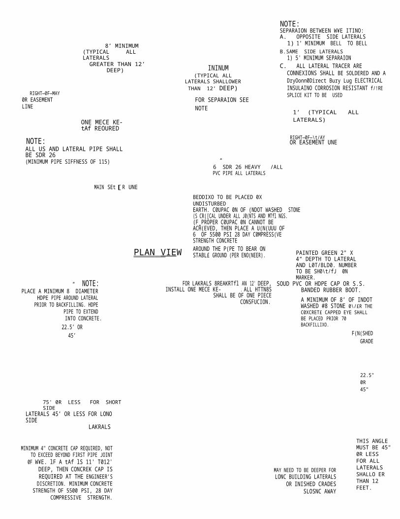
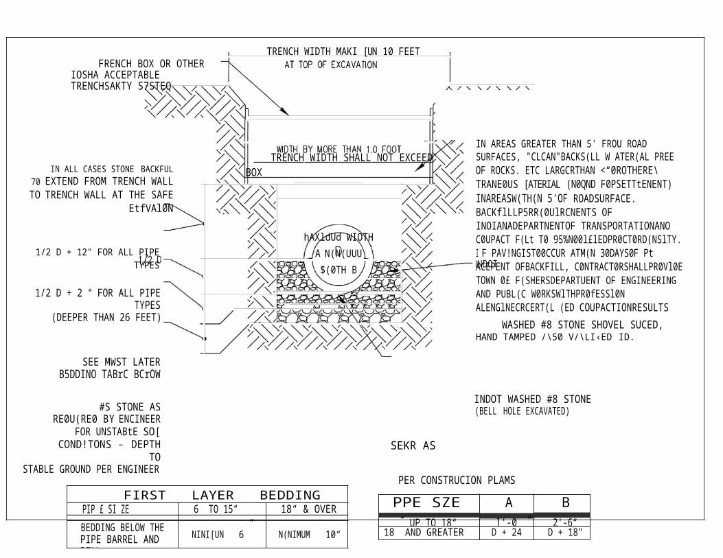
Figure 1-1: Unacceptable Lateral Connection Detail Figure 1-2: Acceptable Lateral Connection DetailFigure 1-3: Typical Type 1 & 2 Clean-out Details Figure 1-4: Typical Type 3 Clean-out DetailsFigure 1-5: Service Lateral DetailFigure 1-6: Service Lateral Detail (For Laterals deeper than 25’ only) Figure 1-7: Sanitary Sewer Trenching, Bedding and Backfill Detail
Appendix A: Application for Connection Permit Appendix B: Plot Plan Standards

©Copyright 2018 by Sanitary Management & Engineering Company, Inc.
Revision Date – 4/23/18X:MSWorddocs\Standards&Specifications\Lateral
3
1.1 GENERAL
A. DefinitionsFor the purposes of these Standards for Design and Construction of Laterals (“Standards”), the following definitions shall apply:
1. “HSE” shall mean Hamilton Southeastern Utilities, Inc., the public utility which provides sanitary sewer service in the Project (as hereafter defined) area. HSE’s address is 11901 Lakeside Drive, Fishers, Indiana 46038, and HSE’s phone number is (317) 577-2300.
2. “Engineer” shall mean the engineer for HSE, which is Sanitary Management & Engineering Company, Inc. (“SAMCO”) or SAMCO’s engineers. SAMCO’s inspector shall be the Engineer’s representative during construction of Laterals. SAMCO’s address is 11905 Lakeside Drive, Fishers, Indiana 46038, and SAMCO’s phone number is (317) 577-1150.
3. “Owner” shall mean the property owner of record whose deed is recorded at the Hamilton County Recorder’s office. This definition is intended to include all contractors, sub-contractors and/or agents acting for or on behalf of the Owner.
4. “Contractor” shall mean any construction contractor approved by HSE to construct, install, maintain, repair and remove Laterals (as hereafter defined) within the HSE service area. This definition is intended to include all employees, sub-contractors and/or agents acting for or on behalf of the Contractor’s company.
5. “Lateral” shall mean any pipe (gravity or force main) which runs from the Owner’s buildings, structures, property or premises (“Owner’s Premises”) to the main line sewer which receives sewage from the Owner’s Premises. Laterals are also commonly known as “service pipes,” “building sewers” and “service connections” but are herein referred to as Laterals.
6. “Project” shall mean any sanitary sewer facilities constructed within the service area of HSE and shall include all work necessary for the installation of all sanitary sewer infrastructure and appurtenances in conformity with HSE approved construction plans and the standards, specifications, and details of HSE.
7. “Conveyed” with regards to sanitary sewer facilities means Projects for which HSE has received title.

©Copyright 2018 by Sanitary Management & Engineering Company, Inc.
Revision Date – 4/23/18X:MSWorddocs\Standards&Specifications\Lateral
4
8. “Completed” with regards to Projects shall mean any Projects which are acceptably constructed, tested and through which customer service has been authorized by HSE. All applicable fees must be paid to HSE prior to a Project being deemed Completed.
B. Purpose
The purpose of these Standards is to provide the general rules and policies set forth for the construction of Laterals within the HSE service area. It is the intent of these Standards to provide interested parties with a concise statement of the policies governing the sanitary sewer connection permit (“Permit”), construction and completion processes of Laterals.
C. ApplicabilityThese Standards are applicable for all Laterals which will be connected to HSE’s sanitary sewer system. This includes Projects (including on-site disposal systems) which will not initially be connected to HSE’s sanitary sewer system but at some future date may be connected to the system.
D. Liability and CostNo direction, field directive, or other instruction contemplated by these
Standards and/or conducted by others shall accrue any liability, charge or cost to HSE, Engineer or Engineer’s inspectors. The utility will not assume responsibility for noncompliance with the referenced specifications as a result of information not provided in these Specifications.
E. Standards, Specifications and Details
1. These Standards and HSE’s other standards, specifications and details are subject to revision at any time prior to the start of construction of the Lateral. These documents are also subject to revision at any time during construction when, in Engineer’s opinion, those revisions materially affect the maintenance, operations or life of the Lateral.
2. HSE reserves the right to modify or waive any of these Standards and/or its other standards, specifications and details in its best interest.
3. These Standards are intended to define the construction requirements of Laterals which are constructed and operated under typical conditions in HSE’s service area. Depending on field conditions and the composition and characteristics of the

©Copyright 2018 by Sanitary Management & Engineering Company, Inc.
Revision Date – 4/23/18X:MSWorddocs\Standards&Specifications\Lateral
5
sanitary sewer flow, different or unusual conditions may occur which cannot be anticipated in a document of this nature. Consequently, Engineer may impose additional or special construction requirements under such circumstances.
F. Drawing Discrepancies and Omissions
1. Prior to the start of construction, the Contractor must notify Engineer of any conflicts between the construction drawings, any supplemental information supplied by HSE and/or these Standards. Resolution of any such conflict shall be at the Engineer’s sole discretion.
2. Any items which are not covered in these Standards, the construction drawings or HSE’s other standards, specifications and details, but are required for construction of the Lateral, must be approved by Engineer prior to installation of the Lateral.
3. In the event construction practices are not described herein, but in Engineer’s opinion, will affect the quality of construction or maintenance of the Lateral, the Engineer must approve any construction practices proposed by the Contractor.
G. Governing Laws, Codes and Regulations
1. Construction practices must meet all applicable laws, codes or regulations and be in accordance with the requirements of all governmental agencies and public entities having jurisdiction.
2. These Standards shall not be considered as a substitute, nor shall they supersede, any state or federal law, code or regulation related to construction of Laterals. In the event of a conflict between any state or federal law, code or regulation governing the design and/or construction of Laterals and these Standards, the more stringent requirement will apply.
3. All persons on site must abide by all Indiana Occupational Safety and Health Administration (“IOSHA”) standards including but not limited to “General Construction Practices” and “Trench Safety Standards.” The responsibility for safety measures rests solely with the Contractor. All excavations must adequately guard the public by barricades, fences, lights and other such means as necessary.
H. NoticesAll notices required by these Standards must be given to both HSE and Engineer at their respective business offices.
©Copyright 2018 by Sanitary Management & Engineering Company, Inc.
Revision Date – 4/23/18X:MSWorddocs\Standards&Specifications\Lateral
6
I. Confined Space EntryAll persons, including but not limited to Owners, Contractors, sub-contractors, etc. must abide by HSE’s “General Procedures for Manhole Opening and Entry” or the most recent IOSHA confined space entry standards, whichever is more stringent.
J. MaintenanceLaterals must be maintained in compliance with HSE’s current “Maintenance Specifications for Sewer Facilities”
K. Compliance1. Laterals must comply with the latest published edition of
American Water Works Association (“AWWA”), American Society for Testing and Materials (“ASTM”), American National Standards Institute (“ANSI”) and Uni-Bell PVC Pipe Association (“UNI”) standards or as indicated in these Standards, whichever is more stringent.
2. Engineer’s decisions shall be final. Failure to comply with HSE’s standards, specifications, details or field directives/decisions shall be grounds for removal from the HSE approved contractor list.
1.2 LATERALS
A. Lateral Connection Permit
1. Connection Permits A Permit must be issued by HSE for all repairs, modifications or connections to Laterals. In addition, Permits are required for expansions of existing buildings.
2. Minimum Elevations for Gravity Connection Owner shall verify that the lowest elevation to have gravity sanitary sewer service within the home or building is more than one (1) foot above the lowest top of casting elevation of either the first upstream or downstream manhole on the main line sewer to which the connection is to be made. (See Figures 1-1 and 1-2). If the vertical separation cannot be maintained, then the Owner must sign a Waiver of Responsibility which will be recorded against the deed of record.
Applicant should carefully consider the lowest elevation to have gravity sanitary service. For example, the invert of trench drains or the outlet of a swimming pool sump pit may potentially be the point of lowest elevation.

©Copyright 2018 by Sanitary Management & Engineering Company, Inc.
Revision Date – 4/23/18X:MSWorddocs\Standards&Specifications\Lateral
7
Prior to the installation of a Lateral, the Contractor shall field verify compliance with the minimum elevation for gravity connection.
If at the time of application for the permit an “As Built Top of Casting” elevation is not available then the lowest elevation to have gravity sanitary sewer service with in the home or building must be set two (2) feet above the lowest “plan grade” shown for either the upstream or downstream manhole on the main line sewer to which the connection is to be made.
3. Permit Fee A fee as defined in HSE’s current tariff shall be charged on a per Equivalent Dwelling Unit (“EDU”) for a Permit. Any re-inspection which may be necessary because of defective workmanship or incomplete construction will be assessed a re-inspection fee.
4. Application for Permit A Permit application must be made on the form prescribed by HSE and available from the utility at 11901 Lakeside Drive, Fishers, IN 46038. An application is included in Appendix A. All easements required by Engineer must be approved and recorded prior to issuance of the Permit.The application will require at a minimum the following information:a. Name and address of the Owner;b. Name, address and telephone number of the Contractor;c. Address;d. If required, a legal description of the Owner’s property
for which the Permit is being requested;e. Plans for the Lateral and connection, which at a
minimum must consist of the following:(1) Plot Plan according to HSE’s Plot Plan
Standards. Refer to Appendix B;(2) Connection details including location of
connection and routing of the Lateral;(3) Material of construction for the Lateral;(4) Elevation of the first floor and lowest point of
gravity service. All elevations must be on the same vertical datum as the HSE approved construction plans; therefore a conversion between different datum may be necessary.
5. Who May Apply The following can only apply for a Permit:a. Home Builders

©Copyright 2018 by Sanitary Management & Engineering Company, Inc.
Revision Date – 4/23/18X:MSWorddocs\Standards&Specifications\Lateral
8
b. Ownerc. At the discretion of HSE, persons other than those listed
above may apply for a Permit.Note: HSE may deny Permits to any applicant who has
previously violated, or is currently in violation of, these Standards or any other HSE rules, regulations, standards, specifications or details.
6. Expiration of Permit
a. The Permit will expire if work is not initiated within one year from the date of issuance. Upon expiration, a new Permit, including payment of the Permit fee, will be required.
b. HSE may for good cause extend the duration of the Permit for a reasonable period. Requests for extension of the Permit period must be submitted in writing to HSE in advance of the expiration and must state the reason for the request. Requests for extension must be forwarded to:
HAMILTON-SOUTHEASTERN UTILITIES, INC. 11901 LAKESIDE DRIVE FISHERS, IN 46038 ATTENTION: PERMT TECHNICIAN
B. Prohibition Against Clear Water Discharges
1. The following sources of clear water shall not be connected to any Lateral:a. Foundation/footing drainsb. Sump pumps with foundation drains or other clear water
sourcesc. Roof drainsd. Heat pump/Geo-Thermal dischargee. Cooling water and/orf. Any other sources of clear/unpolluted waterAny person found violating any provision listed above will be required to correct such connection at their expense and as directed by the Engineer within thirty (30) days of notification. Failure to comply may result in termination of service by HSE.
2. De-watering Discharge to a Sanitary Sewera. Keep excavations free from water until all sanitary sewer
facilities are completed. Provide sufficient dikes and de-

©Copyright 2018 by Sanitary Management & Engineering Company, Inc.
Revision Date – 4/23/18X:MSWorddocs\Standards&Specifications\Lateral
9
watering equipment and make satisfactory arrangements for the disposal of the water without undue interference with other work, damage to property or damage to the environment. Water disposal must be in compliance with the regulations of the Environmental Protection Agency (“EPA”), Indiana Department of Environmental Management (“IDEM”), Soil Conservation Service (“SCS”) and all other applicable agencies.
b. Contractor shall prevent all water from entering the Lateral. In the event any water enters Completed sanitary sewer facilities, the Contractor is responsible to HSE for the costs of sewage treatment, electrical power, equipment repairs, incidental damages, cleaning and any other costs or expenses related to such entry. In addition, Contractor shall pay HSE damages of $300 per occurrence.
c. Contractor must, at Engineer’s discretion, provide de-watering equipment, shoring or other construction practices deemed necessary by Engineer.
3. In the event a home or building has a floor drain or trench drain connected into the Lateral, all site grading must prevent surface water from discharging into the sanitary sewers. Also, when floor drains or trench drains are installed in rooms with exterior connections, either a three (3) inch sill must be added to the exterior doors or the finished floor elevation of the rooms must be installed three (3) inches above surrounding finished grade.
4. HSE requires that all Laterals shall be subject to video camera inspection at the time of initial installation. At the Engineer’s discretion, Laterals may also be inspected by video camera at any time after the initial installation. In addition to the above video camera inspection, the Engineer may require the following additional tests to identify sources of inflow/infiltration (I/I):
a. Low pressure air testb. Smoke testingc. Dye testd. Vacuum test of manholee. Flow monitoring
5. In the event an industrial or commercial entity finds it necessary to discharge clear water consisting of cooling water and/or steam condensate into HSE’s sanitary sewer system and the main line sewer has capacity to receive such clear water without affecting existing or future users, then HSE may enter into an agreement
©Copyright 2018 by Sanitary Management & Engineering Company, Inc.
Revision Date – 4/23/18X:MSWorddocs\Standards&Specifications\Lateral
10
for such discharge. The agreement will define a metering system and any other requirements deemed necessary to measure the flow. The user rate for such discharges will be calculated as provided by HSE’s established rate schedule.
C. Notice of ViolationHSE will issue a “Notice of Violation” whenever it determines that:
1. Construction is proceeding in an unsafe manner; or
2. Construction is occurring in violation of these Standards and/or any other applicable HSE standards, specifications or details; or
3. Sewer construction for which a Permit is required is proceeding without a Permit being in force; or
4. Connection of any source for clear water to the Lateral; or
5. A discharge, into HSE’s sanitary sewer system, of any prohibited water or wastes as defined in the “Rules and Regulations of Hamilton Southeastern Utilities, Inc.” as approved by the Indiana Utility Regulatory Commission (“IURC”).
The Notice of Violation will be in writing and will indicate the location and reason for its issuance. One (1) copy of the Notice of Violation will be posted on the property in a conspicuous place and one (1) copy will be delivered to the Permit holder. HSE may refuse to provide sanitary sewer disposal service or refuse to allow work to resume until Engineer issues a written notice of proper compliance.
D. Mandatory Inspection of Building Connections
1. Notification It shall be the duty of the holder of a Permit to notify HSE that the sewer work is available for inspection. Notification must be provided at least seventy-two (72) hours before inspection is desired. Engineer will conduct inspections on Laterals from 8:00 a.m. to 3:00 p.m. local time, Monday through Friday, except for observed holidays.
The Contractor will be responsible for ensuring that the following items have been completed prior to scheduling the Hook-up:
a. Contract for sewer service has been executed.b. Approved Plot Plan in HSE scanned document file.c. The HSE connection permit has been issued.d. All fees have been paid.The Lateral, in its entirety from the foundation to the

©Copyright 2018 by Sanitary Management & Engineering Company, Inc.
Revision Date – 4/23/18X:MSWorddocs\Standards&Specifications\Lateral
11
connection with the public sewer or existing lateral must be exposed for inspection and be constructed in accordance with these Standards. Under no circumstances shall the Lateral be backfilled without an inspection by Engineer.
2. Video Camera Inspection a. Within 90 days after initial installation, each Lateral shall
be inspected by video camera. Engineer shall perform the video camera inspection and inspect for the following:(1) Joint separation/off-set joint.(2) Construction debris (stone, broken pipe, mud,
etc.) in Lateral or main line sewer.(3) Properly installed joints.(4) Deformed pipe.(5) Cracks in pipe.(6) Infiltration.(7) Number of fittings and distance between clean-outs.
b. At the sole discretion of Engineer, Contractor may be required to clean, repair or replace defects identified during the video camera inspection.
c. Depending on the type of defects identified during the above video camera inspection or the type of repair, Engineer may also require Contractor to perform a low-pressure air test of the Lateral or an individual joint.
3. Right of Entry Engineer shall have the right of entry to, upon or through the Owner’s Premises for purposes of inspection of Laterals or to determine if any sources of clear water are connected to the Lateral.
E. Lateral Construction1. Materials
a. Pipe and fittings used in Lateral construction shall be
smooth wall inside and out, and must be either: Polyvinyl Chloride (“PVC”) and must conform to ASTM D-3034 SDR 26. (Fittings must be SDR 26 minimum wall thickness), Type PSM or CAN/CSA- B182.2.M90, the more stringent shall apply; or ASTM D-2241 (SDR 21).Or
HDPE pipe must meet ASTM D3350 and meet HSE
©Copyright 2018 by Sanitary Management & Engineering Company, Inc.
Revision Date – 4/23/18X:MSWorddocs\Standards&Specifications\Lateral
12
standard for Horizontal Directional Drilling and Piping.
b. Joints must be either:
Flexible gasket push-on compression type for PVC pipe. The joint must comply with ASTM F-477, and the physical requirements of ASTM D- 3212, and UNI-B-1 “Recommended Specifications for Thermoplastic Pipe Joints. Pressure and Non-Pressure.”, the more stringent shall apply. The gasket must be the only element depended upon to make the joint flexible and watertight.
Or
Solvent cement type with colored primer assembled in a manner directed by Engineer for PVC pipe.
Do not use primer or cement that is gelled. Cut the pipe square and remove all burs and beads. Clean with a dry rag and check fit prior to adding cement.
Install primer aggressively and keep wet, do not allow puddling. Apply first to inside surface, then to outside surface and then repeat to inside surface.
Cement is to be installed while primer is still wet. Apply first to outside surface then to inside surface and then repeat to outside surface.
Assemble while wet and turn ¼ revolution to evenly distribute. Hold in place for 1 minute. Clean off excess cement and allow to cure properly (in cold weather, more time and additional applications are required. i.e. 4 hour minimum at 20° F).
Solvent welding procedures to comply with ASTM D2855
and D1785.
Or
HDPE pipe joints to be fusion welded and meet ASTM D3261. They must be made by an experienced installer and meet all HSE standards for HDPE pipe.

©Copyright 2018 by Sanitary Management & Engineering Company, Inc.
Revision Date – 4/23/18X:MSWorddocs\Standards&Specifications\Lateral
13
2. Installation of Laterals
a. PermitA Permit must be issued by HSE prior to the installation of a Lateral.
b. Approved Contractors(1) Contractors pre-approved by HSE must construct
Laterals. Any Lateral installed by contractors not pre-approved by HSE will be rejected. A list of pre-approved contractors may be obtained at HSE’s office.
(2) Approved Contractors shall not sub-contract Lateral installation work to anyone other than an HSE approved Contractor.
(3) Each supervisor, foreman or superintendent and pipe layer assigned by Contractor to supervise on-site installation of Laterals shall also be pre-approved by HSE and be recertified annually.
(4) To maintain approval by HSE, a Contractor must install a minimum of ten (10) Laterals per calendar year.
(5) Approved Contractors must submit a Standardized Pre- Qualifications Form (PQF) annually to maintain approval.
c. Minimum Size, Fittings and Clean-outs(1) Laterals must be a minimum of six (6) inches in
diameter and sized based on the anticipated flows. For example, a lateral servicing a pool house may need to be larger based on the peak filter backwash flow. Laterals must have a wye clean-out located within three (3) feet of the building's exterior wall and subsequent clean-outs must be installed at a maximum interval of one hundred (100) feet. Therefore no section of Lateral between the building and main line sewer shall exceed one hundred (100) feet without the installation of a clean-out.
(2) It is recommended that a clean-out be installed after every three(3)fittings of 22.5 degrees or more, but in no case
exceeding five(5) fittings between clean-outs. All fittings must be 45 degrees or less. Engineer will not permit fittings of greater than 45 degrees. Also, when deemed necessary by the Engineer a clean-out must be installed.

©Copyright 2018 by Sanitary Management & Engineering Company, Inc.
Revision Date – 4/23/18X:MSWorddocs\Standards&Specifications\Lateral
14
(3) All clean-outs must be the same diameter as the horizontal Lateralinto which the clean-out is connected; minimum of six (6) inches.
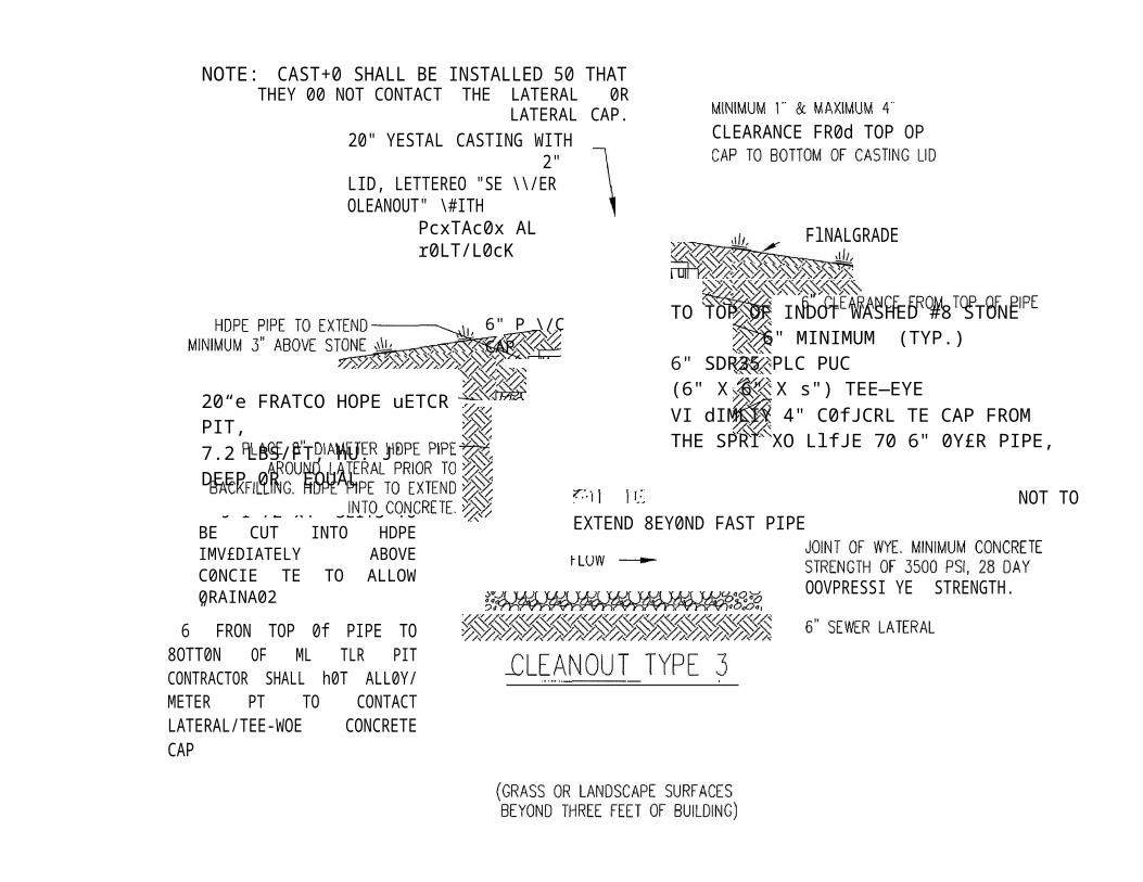
(4) All clean-outs must be extended to grade and capped per HSE’s requirements. Clean-outs installed in grass or landscape areas and located within three (3) feet of the building’s exterior wall must be installed per clean-out Type 1 of Figure 1-3. All other clean-outs must be installed per clean-out Type 2 or Type 3 of Figure 1-3 and 1-4. In order to avoid cap damage, Engineer will also require that all clean-outs installed greater than three (3) feet from the building’s exterior wall be installed as Type 2 in hard surface area or a Type 3 in landscape or grass area. Under no circumstances shall clean-outs be buried. If the lateral extends above the Building Foundation then compacted granular backfill must be installed per figure 1-6. HSE Approved Contractor shall be solely responsible for installation and compaction of granular material. Any future settlement of Lateral or damage caused by settlement shall be the sole responsibility of HSE Approved Contractor.
(5) Fiber mesh reinforcement for Type 2 clean-outs: Application per cubic yard shall equal a minimum of 1.5 pounds. Fibers are for the control of the following: cracking due to drying shrinkage and thermal expansion/contraction, to lower concrete permeability and to increase impact capacity, shatter resistance and abrasion resistance. Fibermesh, 4019 Industry Drive, Chattanooga, Tennessee, 37416 or equal as approved by Engineer on a case by case basis, must manufacture fiber mesh reinforcement.
d. Slope(1) Slope requirements must conform to the latest
edition of the State of Indiana (Uniform Plumbing Code), local codes and to these Standards, whichever is more stringent.
(2) Laterals must be installed at a minimum of 1.00% and where possible, not exceed 6.00%. Engineer, depending on site conditions, may waive the slope requirements.
e. Connection to Main Line Sewer(1) Laterals are not allowed beyond those installed

©Copyright 2018 by Sanitary Management & Engineering Company, Inc.
Revision Date – 4/23/18X:MSWorddocs\Standards&Specifications\Lateral
15
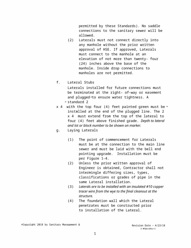
during original construction and must connect to the sanitary sewer only at manufactured fittings (except as otherwise permitted by these Standards). No saddle connections to the sanitary sewer will be allowed.
(2) Laterals must not connect directly into any manhole without the prior written approval of HSE. If approved, Laterals must connect to the manhole at an elevation of not more than twenty- four (24) inches above the base of the manhole. Inside drop connections to manholes are not permitted.
f. Lateral StubsLaterals installed for future connections must be terminated at the right- of-way or easement and plugged to ensure water tightness. A standard 2”
x 4” with the top four (4) feet painted green must be installed at the end of the plugged line. The 2” x 4” must extend from the top of the lateral to four (4) feet above finished grade. Depth to lateral and lot or block number to be shown on marker.
g. Laying Laterals
(1) The point of commencement for Laterals must be at the connection to the main line sewer and must be laid with the bell end pointing upgrade. Installation must be per Figure 1-4.
(2) Unless the prior written approval of Engineer is obtained, Contractor shall not intermingle differing sizes, types, classifications or grades of pipe in the same Lateral installation.
(3) Laterals are to be installed with an insulated #10 copper tracer wire from the wye to the final cleanout at the structure.
(4) The foundation wall which the Lateral penetrates must be constructed prior to installation of the Lateral.
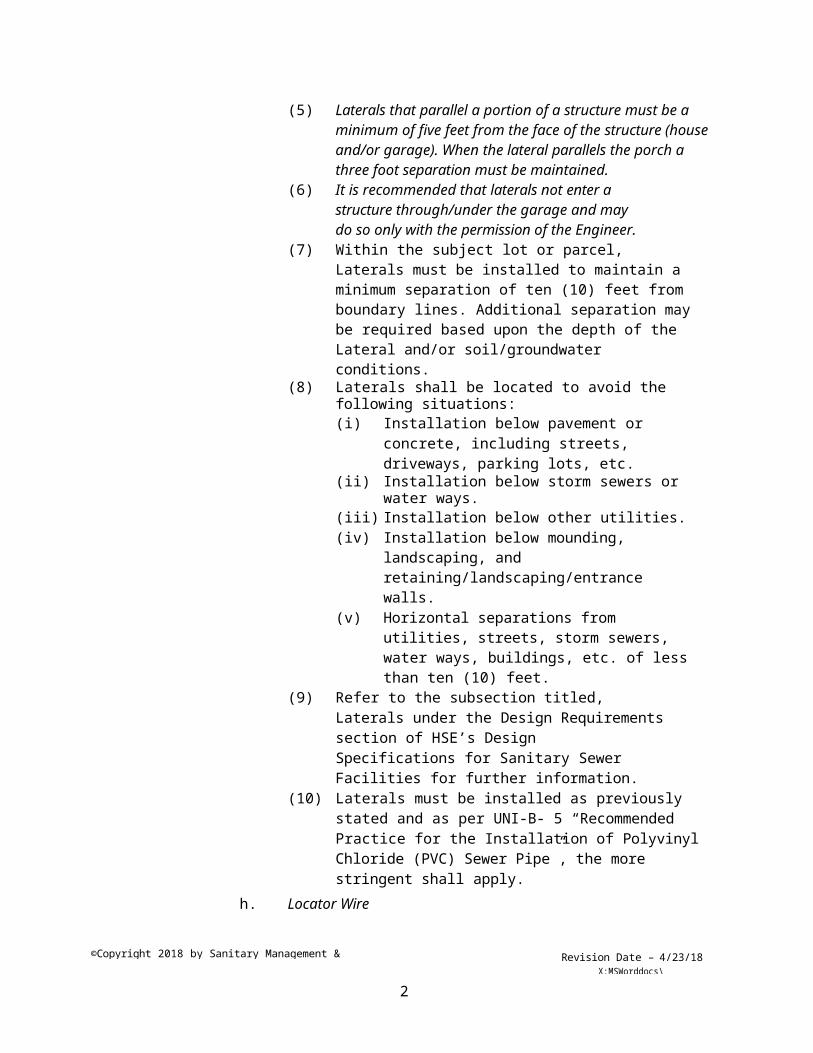
(5) Laterals that parallel a portion of a structure must be a minimum of five feet from the face of the structure (house and/or garage). When the lateral parallels the porch a three foot separation must be maintained.
(6) It is recommended that laterals not enter a structure through/under the garage and may do so only with the permission of the Engineer.
©Copyright 2018 by Sanitary Management & Engineering Company, Inc.
Revision Date – 4/23/18X:MSWorddocs\Standards&Specifications\Lateral
16
(7) Within the subject lot or parcel, Laterals must be installed to maintain a minimum separation of ten (10) feet from boundary lines. Additional separation may be required based upon the depth of the Lateral and/or soil/groundwater conditions.
(8) Laterals shall be located to avoid the following situations:(i) Installation below pavement or
concrete, including streets, driveways, parking lots, etc.
(ii) Installation below storm sewers or water ways.
(iii) Installation below other utilities.(iv) Installation below mounding,
landscaping, and retaining/landscaping/entrance walls.
(v) Horizontal separations from utilities, streets, storm sewers, water ways, buildings, etc. of less than ten (10) feet.
(9) Refer to the subsection titled, Laterals under the Design Requirements section of HSE’s Design Specifications for Sanitary Sewer Facilities for further information.
(10) Laterals must be installed as previously stated and as per UNI-B- 5 “Recommended Practice for the Installation of Polyvinyl Chloride (PVC) Sewer Pipe”, the more stringent shall apply.
h. Locator Wire
(1) Mainline contractor is to install insulated #10 copper tracer wire along the top of pipe from the wye to the lateral marker. At the marker the wire is to be extended to the surface.
(2) Lateral contractor is to connect to the tracer wire at the marker and extend the wire along the top of pipe to the cleanout adjacent to the structure.
i. Wye and First Pipe for Deep Mainlines(1) From the wye installed on the sewer main the first
length of pipe on all long side laterals must be laid upon undisturbed ground, bedded in a minimum of six (6) inches of #8 stone. The first length of pipe for the short side lateral may be laid upon fill made up of #8 stone. If the sewer is deeper than 25 feet then both long side and short side laterals
©Copyright 2018 by Sanitary Management & Engineering Company, Inc.
Revision Date – 4/23/18X:MSWorddocs\Standards&Specifications\Lateral
17
may not be laid at a slope greater than 45 degrees
j. Bedding and Backfill(1) Bedding and backfill must meet all requirements
set in Figure 1-6 of these Standards and the manufacturer's recommendations, whichever is more stringent.
(2) To prevent or minimize trench settling and consequently Lateral failure, the Contractor shall place granular backfill compacted to 95% modified proctor density vertically from the building foundation to the #8 stone pipe bedding; and horizontally from the foundation wall to undisturbed earth.
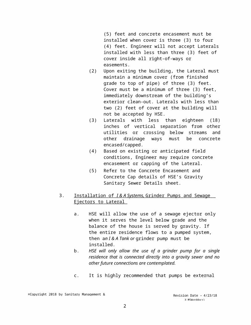
k. Cover and Concrete Capping/Encasement(1) Laterals must maintain a minimum cover (from
finished grade to top of pipe) of five (5) feet within all right-of-ways or easements. If minimum cover cannot be maintained, then a concrete cap must be installed when cover is four (4) to five (5) feet and concrete encasement must be installed when cover is three (3) to four (4) feet. Engineer will not accept Laterals installed with less than three (3) feet of cover inside all right-of-ways or easements.
(2) Upon exiting the building, the Lateral must maintain a minimum cover (from finished grade to top of pipe) of three (3) feet. Cover must be a minimum of three (3) feet, immediately downstream of the building’s exterior clean-out. Laterals with less than two (2) feet of cover at the building will not be accepted by HSE.
(3) Laterals with less than eighteen (18) inches of vertical separation from other utilities or crossing below streams and other drainage ways must be concrete encased/capped.
(4) Based on existing or anticipated field conditions, Engineer may require concrete encasement or capping of the Lateral.
(5) Refer to the Concrete Encasement and Concrete Cap details of HSE’s Gravity Sanitary Sewer Details sheet.
3. Installation of I & A Systems, Grinder Pumps and Sewage Ejectors to Lateral
©Copyright 2018 by Sanitary Management & Engineering Company, Inc.
Revision Date – 4/23/18X:MSWorddocs\Standards&Specifications\Lateral
18
a. HSE will allow the use of a sewage ejector only when it serves the level below grade and the balance of the house is served by gravity. If the entire residence flows to a pumped system, then an I & A Tank or grinder pump must be installed.
b. HSE will only allow the use of a grinder pump for a single residence that is connected directly into a gravity sewer and no other future connections are contemplated.
c. It is highly recommended that pumps be external to the building. Sewage backups into the wet well/building may occur due to failure of the pump, check valve or appurtenances, thus allowing sewage to flow into the wet well/building. Any backup into the wet well/building will be the sole responsibility of the Owner. HSE is not liable or responsible in any way for damages due to sewage backups in wet wells/buildings served by grinder/ejector pumps.
d. All pumps must have high level alarm, check valve and shutoff valve suitable for sewage applications.
e. All I & A Tanks, grinder pumps and effluent pumps must have an electrical disconnect switch, approved by HSE, mounted adjacent to the wet well.
f. All piping or facilities installed exterior to the building must be installed by an HSE approved Contractor.
g. All exposed piping must be Schedule 40 galvanized steel.
h. All buried piping must be a minimum of either PVC SDR 21 conforming to ASTM D-2241, PE DR 11, or Schedule 40 conforming to ASTM D- 1785.
i. Galvanized pipe must be threaded connections and PVC pipe must be either solvent weld or gasketed push on joint connections conforming to ASTM D-3139 or AWWA C-900.
j. The pump discharge must connect to the Lateral or common force main at locations approved by HSE in writing.
k. Force main connections to HSE’s sanitary sewer facilities shall be allowed only as approved by HSE in writing.
©Copyright 2018 by Sanitary Management & Engineering Company, Inc.
Revision Date – 4/23/18X:MSWorddocs\Standards&Specifications\Lateral
19
l. Wet well/sump must be FRP or concrete and must be
specifically designed for this application. The wet well shall be constructed as specified in HSE’s specifications and details to prevent infiltration or inflow. Engineer may require vacuum testing of the wet well/sump. Refer to the Manhole Testing section of HSE’s Gravity Sanitary Sewer Specifications sheet for further information on vacuum testing. Engineer will not permit the use of septic tanks connected to the sanitary sewer.
m. The operation, maintenance, repair and replacement of the pump and appurtenances shall be the sole responsibility of the Owner. This also includes the force main and/or gravity Lateral from the building to its connection into the sanitary sewer main.
n. Installation must conform to all national, state, and local building codes.
o. The top of the wet well/sump must be:(1) Eighteen (18) inches above the current published
DNR 100 year flood elevation of nearby waterways.
(2) And it is highly recommended to be one (1) foot below the lowest elevation to have sanitary service in the home or building.
(3) If the owner chooses not to maintain the standards for elevation of the top of the wet well/sump then a Waiver of Responsibility must be recorded.
F. Lateral Length
1. If a Lateral must cross property owned by another entity other than the Owner, then the Lateral must be constructed in a dedicated easement approved by Engineer. A Permit will not be issued until the easement has been approved by Engineer and recorded.
2. Unless HSE, in writing, determines that an exception is justified, no more than one hundred (100) feet of a Lateral shall exist outside of the boundary of the lot or tract for which the Lateral is designed to service.
3. No Lateral shall be greater than two hundred (200) feet in overall length unless the prior written approval of Engineer is obtained.
©Copyright 2018 by Sanitary Management & Engineering Company, Inc.
Revision Date – 4/23/18X:MSWorddocs\Standards&Specifications\Lateral
20
4. As stated above, no section of Lateral shall exceed one hundred (100) feet without the installation of a clean-out.
G. Maximum Number of Building Connections
1. No more than one (1) building or residence will be permitted to connect into a lateral unless the prior written approval of Engineer is obtained.
2. Except two existing residences may be served from one lateral.
H. Owner’s Lateral Responsibility
1. All costs for initial installation, subsequent repair, relocation, change or replacement of Laterals shall be at the Owner’s expense.
2. Owner may place or permit to be placed any trees or other deep rooted landscaping with separation as specified in the current (at the time of planting) HSE Approved Tree List. For trees not listed in the HSE Approved Tree List a Minimum separation of ten (10) foot horizontal distance for Laterals or any other sanitary sewer facilities (as measured from the drip line of the mature tree to the center of sanitary sewer facilities) must be maintained. Any trees or landscaping placed within easements or right-of-ways are at risk of being damaged or removed by HSE without the obligation of replacement.
3. Owner shall not place or permit to be placed any mounding, lighting, fencing, signs, retaining/landscaping/entrance walls, irrigation lines, etc. directly over or within ten (10) foot horizontal distance of Laterals or any other sanitary sewer facilities (as measured from the nearest edge to the center of sanitary sewer facilities). Any of the above listed items placed within easements or right-of-ways are at risk of being damaged or removed by HSE without the obligation of replacement.
4. Prior written approval by HSE must be obtained for all grade changes across sanitary sewer facilities located within easements or right-of-ways.
5. Extreme care must be taken while landscaping or excavating to protect the Lateral from damage. Contact Indiana Underground Plant Protection Service at 1-800- 382-5544 prior to commencing such work.

©Copyright 2018 by Sanitary Management & Engineering Company, Inc.
Revision Date – 4/23/18X:MSWorddocs\Standards&Specifications\Lateral
21
6. It shall also be the responsibility of the Owner to insure that all manhole and clean-out top of castings extend a minimum of 0.20 feet above finished grade and are not buried, sodded over, placed in concrete or pavement (including driveways and sidewalks), or obstructed in any way. Manhole top of castings must have a minimum of one (1) foot separation from sidewalks and driveways. If a casting must be raised to comply with HSE’s standards, Engineer will not permit more than a total of twelve (12) inches of riser rings in that structure. In the event the desired elevation cannot be obtained without more than a total of twelve (12) inches of riser rings, it will be the responsibility of the Owner to add additional barrel sections to the structure. This work must be performed by an HSE approved Contractor and tested in compliance with HSE’s Gravity Sanitary Sewer Specifications. Raising top of casting elevations may affect the minimum elevation for gravity connection for multiple lots or connections as described in these Standards.
7. Engineer may periodically perform field inspections to verify
compliance with the above mentioned requirements. If a violation exists then the Owner mustimmediately remedy the situation.
8. In the event, Engineer determines that a violation, as previously described, exists within Owner’s Premises, Engineer will notify the Owner in writing. The notice will describe the nature of the violation and the corrective action(s) which must be taken. Such corrective action must be taken within thirty (30) days of receipt of such notice or the Owner may risk termination of sanitary sewer disposal service by HSE.
9. Trees or shrubs cannot be planted directly over building laterals.
10. Based on the Ultimate Depth, mounding installed parallel to a sewer must be designed to maintain the same minimum horizontal separations as those indicated for Utility Separation and Utility Crossings in this section of these Design Specifications.
11. Mounding, even when crossing at ninety (90) degrees, must not be constructed directly over sanitary sewer facilities.
I. Protection of Water Supplies
1. There shall be no physical connections between a Lateral and the water supply system or appurtenances thereto which
©Copyright 2018 by Sanitary Management & Engineering Company, Inc.
Revision Date – 4/23/18X:MSWorddocs\Standards&Specifications\Lateral
22
would permit the passage of any polluted water into the potable water supply. Laterals shall be laid at least ten (10) feet horizontally from any existing or proposed water line. The distance shall be measured edge to edge. In cases where it is not practical to maintain a ten (10) foot separation, the appropriate public health agency may allow deviation on a case-by-case basis. Such deviation may allow installation of the sewer closer to a water line, provided that:
a. The water line is in a separate trench or on an undisturbed earth shelf located to one side of the sewer, and
b. At an elevation so the bottom of the water line is at least eighteen (18) inches above the top of the sewer.
c. The lateral pipe must be constructed from water grade pressure pipe.
2. Laterals crossing water mains shall be laid to provide a minimum vertical separation distance of eighteen (18) inches between the outside of the water main and the outside of the sewer. This shall be the case where the water main is either above or below the sewer. The crossing shall be arranged so that the sewer joints will be equidistant and as far as possible from the water line joints. Where a water line crosses under a sewer, adequate structural support shall be provided for the sewer to prevent damage to the water line. When it is impossible to obtain proper horizontal and vertical separation as stipulated above, the Lateral shall be designed and constructed equal to water pipe, and shall be pressure tested to assure water tightness prior to backfilling.
3. Sewer/water supply separations and pipe classifications must conform with 327 IAC 3-6-9.
J. Connection of Existing Homes or Buildings
1. In order to obtain sanitary sewer service, Engineer may require all existing homes or buildings to construct a new Lateral, in accordance with these Standards, from the structure’s foundation to the connection into the main line sewer.
2. Engineer does not normally permit Lateral connections to a main line sewer beyond those installed during original construction; therefore it is imperative that the Owner contact HSE during the design process of the main line sewer.

©Copyright 2018 by Sanitary Management & Engineering Company, Inc.
Revision Date – 4/23/18X:MSWorddocs\Standards&Specifications\Lateral
23
3. An exception will be made to these policies if the existing sewage disposal system was constructed in accordance with these Standards and inspected and approved by HSE or Engineer. Inspection services will be billed at HSE’s current rate to the entity requesting inspection. Prior to connection of an existing system, HSE may require, at its Engineer’s discretion, the following testing to identify potential sources of inflow/infiltration (I/I):
a. Low-pressure air test and/or vacuum manhole test (for sewers without Laterals) according to the HSE’s Sanitary Sewer Standard Specifications.
b. Video camera inspection and/or smoke testing of all lines in the presence of HSE or Engineer.
c. Site inspection of the Owner’s Premises, including the interior of buildings.

SURCHARGED WATER LEVEL BASEMENT F L O O D E D
FLOOR DRAIN
GRAVITY BUILDING SEWER TO WYE
NEAREST UPSTREAM OR DOWNSTREAM MANHOLE ON
MAIN LIVE SEWER
A SANITARY SEWER BUILDING CONNECTION CONSTRUCTED IN THIS SITUATION WILL NOT BE ACCEPTED (SEE THE ACCEPTED SITUATION - FIGURE 1-2)
UNACCEPTABLE BUILDING SEWER CONNECTION DETAIL
©2018, SANITARY MAN AGEMENT & ENGINEERING COMPANY, INC. FIGURE 1-1


MANHOLE RIM MUST BE AT LEAST (1) ONE FOOT
BELOW LOWEST ELEVATION TO HAVE GRAVITY SANITAR Y SEWER
SERVICE.
FLOOR DRAIN
GRAVITY BUILDINGSEWER TO WYE
NEAREST UPSTREAM OR DOWNSTREAM MANHOLE
ON MAIN LINE SEWER
ACCEPTED DESIGN OF SANITAR Y SEWER BUILDING CONNECTION (SEE THE REJECTED DESIGN - FIGURE 1-1)
ACC E PTAB LE BUI L DING S E W E R CONN E CTION D E TAI L
©2018, SANITARY MAN AGEMENT & ENGINEERING COMPANY, INC. FIGURE 1-2

TEuR0RARtGLUCD C*P
NOTE: str SrxB xXD CR4Yit SPACE NOTE: r AIERAL C0fJTRACT0R 70 I#ST/tL
(0NhCT 0dS MUSf B£ A MMdU0 IN TOP OF QEMOO T CAP 4Of 3“ 8£L0t/ THc /001ER 140 f X1 i- i/z’ X 1/\’ Mx4 x1IL xSUE BIJIL0Ixc IT TUC rR0x T 0r M/v‹urxC›IJe£D BY CI‹RISI‹Ix INC. fr‹£ 5IRuCTUP£ TO PR0¥D£ TSC 0£ CINCINNA£. 0610 XXD SEALEO S80RTES T. MOST OIRCCT ROUTE
\ TU EXTCRIOR CLCAR SUIC0#Crx0M TIME BuiL«›‹c t0 tHE SEAL1x+fXSDNO t*TCR*t STUB.
GRAOE
r0«x0ATI0x
(FOOIER)
(6" X 6“ Y 6") T£C— VYE
NOTE' CQCRETL APRON AND CASTING SHALL 8£
TNST*tLED S0 TH*] 7HEY DO NDT
c0NIicI rat tzi£Rfit 0R tfii£Ra UP.
CAST JORDAfl IR0NW0RK5 [ODE1 75AGSTNC CtKRCD 'EAR”
16“ x #” x 6“ CONCRCTC . IRON NTH fi(8CRMt6M
RClNF0RCC@CNt
NDRC PLC AROuNO LAIERAPRIOR 70 BACKFlL¿]Ng.
P(PC )0 EXTCNOC0NCRCT£
.
uIbIfdUM I" C[CARA00£ FROM TOR 0£ CAP IO 80TT0M OF £/ SIIdG FIO
C XP 4hSl0fl J0lrllAROUND L* E9AL
FlNAt @R*DC
6’ PVt RPE
(6“ X 6 X 6)lCt-b*N(MUu *” CONCRETE CAR fR0* TNC SPRINC L(Nt 70 6’ OV£R PIPC. NOTTO EXTtN08tT0ND MRSTRRE JOTNT OF vK MINIMUM CONCRETE
FLO\Y 3- i /2"x " sriTs fo By cuTI« T0 H0P£ IMM£DiAT£LY 1B0vE CQjCRE6 ]0 A L0\Y DRMNACK
fc0W STRCNGtH OF 3*00 PSl 28 VA*C0MPRESH)EStRCN(TN
ANDB*CKF¿ LDC%bL CLEA OUT TYPE l(‹»i‹x L1›05c1PzD Sv9f xCES «+HIx THREE FECT 0r BiJI‹DINC)
B(1O*CNC*EK IRON fD P*tKNT
SCT(NC EXKNO t0 dN0lSTuR8C0
LEANOU T I YPE 2 [HARDSC BE SURFACES ATO ALL OTHER
INST4LL ATI0riS
T’PCAL CtEANOUT DEIALS
N0 TE : TOP 0£ CASTING 0R CLEAU0lJT CAP Srt4U CXT£X0 0.20 F££ T MINIMUM AB0\E FIXISH£0 GRAOC UffL£5S CONSTRUC T£D ATAU P£DESTRI4t4 0£ WHICULAR TR4££I€ MAY. Uf/L£SS / PPR0Y£D BY ENOb££R, SMlf/\ft Y SE\PER CXSIIt'l0S OR CIISd08TS JUST NOTBE <›riIi‹ 0x£ (1) r00T «0RIZ0r TAL DIST»xC£ 0r ANY PA /rD0R ccx‹:Rr\£ S«Rr1c£S,
NOTE:ALL CrC1x0i i PUC ANO FIiTIxcS TO BC PvC SCHC0Jrr ‹00R SDR 35 MSN S8 ALL0NR TUAL I\TEL\/E (I2) FCET. AT0CPT›‹s cxC1TEx THU iKLY£ (12) FCC› M1iERlAL OFC0xSTRiJCTl0x MML BC Dri£9vlx£0 6Y rxGlxrCR.
@AR!H,
SEKR TR£NCHINC, 0CDDIf/G
6“ RVC CAR
MNAL

Figure 1-3

NOTE: CAST+0 SHALL BE INSTALLED 50 THATTHEY 00 NOT CONTACT THE LATERAL 0R
LATERAL CAP.20" YESTAL CASTING WITH
2" LID, LETTEREO "SE \\/ER OLEANOUT" \#ITH
PcxTAc0x AL r0LT/L0cK
CLEARANCE FR0d TOP OP
FlNALGRADE
J—1 /2 x4" SLITS TO BE CUT INTO HDPE IMV£DIATELY ABOVE C0NCIE TE TO ALLOW 0RAINA02
6” FRON TOP 0f PIPE TO 8OTT0N OF ML TLR PIT CONTRACTOR SHALL h0T ALL0Y/ METER PT TO CONTACT LATERAL/TEE-WOE CONCRETE CAP
NOT TO EXTEND 8EY0ND FAST PIPE
OOVPRESSI YE STRENGTH.
20“e FRATCO HOPE uETCR PIT,
7.2 LBS/FT, hU. J' DEEP 0R EOUAL
6" P \/C CAP
TO TOP OF INDOT WASHED #8 STONE
6" MINIMUM (TYP.)6" SDR35 PLC PUC
(6" X 6" X s") TEE—EYEVI dIMLIY 4" C0fJCRL TE CAP FROM THE SPRI XO LlfJE 70 6" 0Y£R PIPE,

”YPICAL CLEANO JT DETAILSFigure 1-
4
NOTE: f0P oF CASTING OR CLEAN0d T SAP SHALL EXIENO 0 20FEET @x uuu *BovE r« SHED CR*st vxrsss CONSTRUCTED WTHN
ENCINEER, SANITARY S£ WEP CASINGS OR CtEAN0UTS NV6T NOT
OEPTHS 0REA f2R THAN TWELVE (12) FEET MATERIAL OFC0R STR dCTI0N FILL 8E DETERuINED BY EL0IJE2R.

RIGHT—0F—MAY
0R EASEMENT LINE
NOTE:
8’ MINIMUM (TYPICAL ALL LATERALS
GREATER THAN 12’ DEEP)
ONE MECE KE-tAf REOURED
ININUM(TYPICAL ALL LATERALS SHALLOWER THAN 12’
DEEP)FOR SEPARAION SEE NOTE
NOTE:SEPARAION BETWEEN W¥E ITINO:A. OPPOSITE SIDE LATERALS
1) 1’ MINIMUM BELL TO BELLB. SAME SIDE LATERALS
1) 5' MINIMUM SEPARAIONC. ALL LATERAL TRACER ARE
CONNEXIONS SHALL BE SOLDERED AND A DryOonn0Direct Bury Lug ELECTRICAL INSULAINO CORROSION RESISTANT f/!RE SPLICE KIT TO BE USED
1’ (TYPICAL ALL LATERALS)
RIGHT—0F—\t/AYOR EASEMENT UNE
ALL US AND LATERAL PIPE SHALL BE SDR 26(MINIMUM PIPE SIFFNESS OF 115) 6” SDR 26 HEAVY /ALL
PVC PIPE ALL LATERALS
MAIN SEt[R UNEBEDDIXO TO BE PLACED 0X UNDISTURBEDEARTH. C0UPAC 0N OF (NDOT WASHEDSTONE (S CR([CAL UNDER ALL J0(NTS AND MTfl NGS.(F PROPER C0UPAC 0N CANNOT BE ACH(EVED, THEN PLACE A U(N(UUU OF 6” OF 5500 PSI 28 DAY C0MPRESS(VE STRENGTH CONCRETE
PLAN VIEW AROUND THE P(PE TO BEAR ON STABL£ GROUND (PER ENO(NEER). PAINTED GREEN 2" X 4“
DEPTH TO LATERAL AND L0T/BLD0. NUMBER TO BE SH0\t/fJ 0N MARKER.NOTE:
PLACE A MINIMUM 8” DIAMETER HDPE PIPE AROUND LATERAL
PRIOR TO BACKFILLING. HDPE PIPE TO EXTEND
INTO CONCRETE.22.5’ OR 45’
75' 0R LESS FOR SHORT SIDE
LATERALS 45’ OR LESS FOR LONO SIDELAKRALS
MINIMUM 4" CONCRETE CAP REQUIRED, NOT TO EXCEED BEYOND FIRST PIPE JOINT 0F
W¥E. lF A tAf lS 11' T012' DEEP, THEN CONCREK CAP IS REQUIRED
AT THE ENGINEER’S DISCRETION. MINIMUM CONCRETE STRENGTH OF
5500 PSI, 28 DAY COMPRESSIVE STRENGTH.
FOR LAKRALS 8REAKRTfl AN 12' DEEP, INSTALL ONE MECE KE- .
ALL HTTN8S SHALL BE OF ONE PIECE
CONSFUCION.
SOUD PVC OR HDPE CAP OR S.S. BANDED RUBBER BOOT.A MINIMUM OF 8’ OF INDOT WASHED #8 STONE 0\/£R THE C0XCRET£ CAPPED EYE SHALL BE PLACED PRIOR 70 BACKFILLIXO.
F(N(SHED GRADE
22.5" 0R 45"
THIS ANGLE MUST BE 45" 0R LESS FOR ALL LATERALS SHALLO ER THAN 12 FEET.
SECTIONNOTE:
ALL LATERAL BEDDING SHALL BE AGAINST
UNDISTURBED TRENCH.
(TYPICAL ALL LATERALS)RGFT-or-wATOR EASEMENT UNE
LOCATOR ARE (TYP ALL LATERALS) (SEE NOTE ”C”)
MUM MAX MU(TYPICAL ALL LATERALS)(s’ vix orF siIE
LATERALS)(SPEC 2.03 C.)
cA r0RFUTURE CONNEXION
(TYPICAL ALL LATERALS)
MINIMUM FALL— 1/8” PER FOOT(TYPICAL ALL LATERALS)
MAY NEED TO BE DEEPER FOR LONC BUILDING LATERALS
OR INISHED CRADES SLOSNC AWAYFROM SEtER.

MORE THAN 12’ DEEP
NOTE’ IFTHE SEER IS DEEPER THAN 25 FEET THEN THE ’ PIPE FOR BOTH LONO SIDE AND SHORT SIDE MAYNOT BE LAID AT A SLOPE GREATER THAN 45 DEGREES. (REFER TO DEEP SERY!CE LATERAL)
LESS THAN 12’ DEEPNOTE: DEPTH OF SERVICE LATERAL SHALL BE MEASURED FROM
FINISHED CRADE TO THE TOP OF MAIN SEVER UNE.ALL PIPINO FROM \YYE TO 45'/22' ri N6 AT 5’—
BEL0Y/ 6RADE SHALL BE SDR 26
SERVICE LATERAL DETAIL FIGURE 1-
5

rLov
MAIN SE\PER LINE
3500 PSI 6’ MIN.CONCRETE EXCASEMEXT
(5” SLUMP MIX)
PAINTED OREEX 2" X 4” DEPTH TO
LATERAL AND L0T/BLD6. NUMBER
70 BE SH0Yf 0N MARKER. (TYPICAL
ALL LATERALS)
LOCATOR \Y!RE(TCP ALL LATERALS)
(SEE NOTE ’C’)
0dE PIECE T£EREQUIRED
TOP VIE//
N0 SCALE
HNISHED ORADE
3500 PSI 6’ MIN. C0XCRET£ ENCASEMEdT (5” SLUMP MIX)
NOTE:SEPARAION BETWEEN th[ IINO:A. OPPOSITE SIDE LATERALS1) 1' MINIMUM BELL TO BELL2) BELL 70 SPI60T MAY BE ADJACENT
%MEN APPROVED BY ENGINEERB. SAME SIDE LATERALS
1) 5’ MINIMUM SEPARATIONC. ALL LATERAL TRACER ARE
C0XdECTI0dS SHALL BE SOLDERED AND A DryConné Direct Bury Luq ELECTRICAL INSULAINO CORROSION RESISTANT\Y!RE SPLICE KIT 70 BE USED
THIS SECION OF LATERAL TO BE LA¥£D ON UNDISTURBED EARTH (F POSSIBLE)
IdD0T WASHED §8 STORE
75’ OR JSSFORSHORTSOELAKRAS 45’ OR LOSS FOR LONG SIDE LATERALS
6" SDR 26 HEAW f/ALL PVC PIPE
45’ BENDS TO BE riLL TO BELL “’DEEP SOCKETADAPKR’ ’ or ITTNG
MANUFACTURED by OPK PRODUCTS, INC.MAIN SEVER UNE
3500 PSl 6’ MlN.CONCRETE ENCASEMENT
(5” SLUMP MIX)
\#!DTH OF SE\PER TRENCH
SERVICELATERALDETAIL(FOR LATERALS DEEPER TITAN 25’ ONLY)
FIGURE 1-6

$2 STONE AS REQUIRED BY Ed0IXEER FOR UXSTABL£ SOIL CONDITIONS — DEPTH T0 STABLE OROUND PER ENGINEER.

FRENCH BOX OR OTHER IOSHA ACCEPTABLE TRENCHSAKTY S7STEQ
TRENCH WIDTH MAKI [UN 10 FEET
IN ALL CASES STONE BACKFUL 70 EXTEND FROM TRENCH WALL
TO TRENCH WALL AT THE SAFE EtfVAl0N
1/2 D + 12" FOR ALL PIPE TYPES
1/2 D + 2 “ FOR ALL PIPE TYPES(DEEPER THAN 26 FEET)
SEE MWST LATERB5DDINO TABrC BCrOW
#S STONE AS RE0U(RE0 BY ENCINEER
FOR UNSTABtE SO[ COND!TONS - DEPTH
TOSTABLE GROUND PER ENGINEER
TRENCH WIDTH SHALL NOT EXCEED BOX
hAXldUd WIOTH A
N(N(UUU $(0TH B
SEKR AS
IN AREAS GREATER THAN 5' FROU ROAD SURFACES, "CLCAN"BACKS(LL W ATER(AL PREE OF ROCKS. ETC LARGCRTHAN <“0ROTHERE\TRANE0US [ATERIAL (N0QND F0PSETTtENENT) INAREASW(TH(N 5'OF ROADSURFACE. BACKflLLP5RR(0UlRCNENTS OF INOIANADEPARTNENTOF TRANSPORTATIONANO C0UPACT F(Lt T0 95%N00l£lEDPR0CT0RD(NSlTY. I F PAV!NGIST00CCUR ATM(N 30DAYS0F Pt ACEPENT OFBACKFILL, C0NTRACT0RSHALLPR0Vl0E TOWN 0£ F(SHERSDEPARTUENT OF ENGINEERING AND PUBL(C W0RKSWlTHPR0fESSl0N ALENGlNECRCERT(L (ED COUPACTIONRESULTS
WASHED #8 STONE SHOVEL SUCED,HAND TAMPED /\50 V/\LI‹ED ID.
INDOT WASHED #8 STONE(BELL HOLE EXCAVATED)
PER CONSTRUCION PLAMSPPE SZE A B
UP TO 18“ ]'-0” 2'-6“18” AND GREATER D + 24” D + 18"
FIRST LAYER BEDDING TABLEPIP £ SI ZE 6” TO 15“ 18“ & OVERBEDDING BELOW THEPIPE BARREL AND BELL
NINI[UN 6” N(NIMUM 10“
SANI TARY SEWER TREN CH! NG, BEDDIN G AND BACKFILL DETA! L
Figure 1-7

Hamilton Southeastern Utilities, Inc.
Application For Sewer Connection 317-577-2300
Office Use Only: Sewer Permit #
Sewer Acct #
Builder Name Phone
Builder’s Address Street City/Zip
Lot Location Lot No. Development Section
Lot Address Street City/Zip
Building Sewer/Lateral Contractor A. Usage SFR MFR Non-Residential Special User Municipal Other
B. Description of Facility _ _ _ _
C. EDU Allocation/Estimated daily gallonage Floating EDUD. Type of Improvement New Remodel Existing Finished Floor Elevation _
E. Sump Pump Yes No Grinder Pump/Effluent Pump Yes No
F. Roof run-off, floor drains & sub-surface drainage to:
Ground Surface Storm Sewer Other (Explain) _
G. Cooling water or geothermal system discharge to:
Ground Surface Storm Sewer Not Applicable Other (Explain) _
I hereby represent and certify that I have the authority and am fully empowered to make the foregoing application, that the application and accompanying plot plan are true and correct, and that all construction of sanitary sewer will comply with all rules, regulations, standards, and specifications currently adopted by Hamilton Southeastern Utilities, Inc. I further certify that storm water (i.e. downspouts, sump pump, surface water drainage, etc.) shall not enter the sanitary sewers and that no connections to sewer mains will be made without inspection and approval of Hamilton Southeastern Utilities, Inc.
The covenants and stipulations herein provided shall extend to and be binding upon the respective heirs, successors and assigns of the location to which sewer service is provided as described herein.
Signature of Builders Authorized Agent _
OFFICE USE ONLY:
Application Approved by Permit Fees Total
(Non-Refundable)Date
Subsequent Connector: Yes No PERMIT VALID FOR ONE YEAR FROM DATE OF ISSUANCEWHITE – HAMILTON SOUTHEASTERN COPY YELLOW – APPLICANTS COPY PINK – BUILDING PERMITX:\
MS Worddocs\Miscellaneous\application for sewer connection form.doc

© Copyright 2018 by Sanitary Management & Engineering Company, Inc.
Revision Date – 4/23/18T:\757\DOCS\001\SPECS\PLOTPLAN 2006.DOC
1
APPENDIX B
HAMILTON-SOUTHEASTERN UTILITIES,
INC. PLOT PLAN STANDARDS
1. Name of the company that prepared the plot plan.
2. Date of drawing/revision dates.
3. Subdivision name/section/lot number.
4. Street address of home/building.
5. North arrow and scale.
6. All drawings must be drawn to scale and plotted with a horizontal scale of 1” = 10’, 20’, 30’, 40’, 50’ or 60’. Note: The scale of the plot plan shall present the information clearly and allow HSE the ability to scale dimensions. If HSE has difficulty scaling dimensions or reading the data, then HSE may request that the plot plan be re-plotted at a different scale.
7. All drawings must be submitted on letter or legal size paper. For more complex projects 24” x 36” sheets will be acceptable.
8. All dimensions, distances, elevations, etc. shall be displayed in English units.
9. Entire boundary of lot or parcel with dimensions labeled per recorded plat or deed. Note: If the lot or parcel is not platted, provide the recording information of the deed.
10. Easements, building lines and right-of-ways per recorded plat. Note: If the parcel is not platted, provide pertinent information from the zoning requirements. (i.e., building set back requirements, etc.)
11. Graphically indicate all revisions due to certificates of correction and provide the recording information.
12. Graphically indicate all easements and right-of ways recorded against the deed and provide the recording information.
13. Elevation of the first floor and lowest point of gravity service (if other than the finished floor elevation).
14. As-built top of casting elevation of the nearest upstream and downstream sanitary sewer manhole. Note: Do not provide the top of casting elevation of sanitary sewer manholes installed with bolted and gasketed castings, instead label the manhole as having a “bolted casting.” Contact HSE to discuss the specific situation in more detail. Manholes with bolted and

© Copyright 2018 by Sanitary Management & Engineering Company, Inc.
Revision Date – 4/23/18T:\757\DOCS\001\SPECS\PLOTPLAN 2006.DOC
2
gasketed castings can not be used as a relief manhole.

© Copyright 2018 by Sanitary Management & Engineering Company, Inc.
Revision Date – 4/23/18T:\757\DOCS\001\SPECS\PLOTPLAN 2006.DOC
3
15. The plot plan must comply with and indicate the following note, “The lowest elevation to have gravity sanitary sewer service must be more than one (1) foot above the lowest top of casting elevation of either the first upstream or downstream manhole on the main line sewer to which the connection is to be made.” Note: If the vertical separation cannot be maintained, then the home or building owner must install either an I&A Tank or a grinder/effluent pump.
16. All elevations on the Plot Plan must be on the same vertical datum as the HSE approved construction plans. Note: Record drawings created for HSE are typically prepared on the NAVD 1988 vertical datum; therefore, the entity preparing the plot plan should consider that as-built elevations may be on a different vertical datum. Conversions between different datum may be necessary.
17. Provide the as-built location of the upstream and downstream manholes, the sanitary sewer main to which the building sewer connects and the wye/lateral. Provide the entire route of the building sewer with all Type 1/2/3 clean-outs identified. Note: Clean-outs installed in grass or landscape areas and located within three (3) feet of the buildings exterior wall can be installed as Type 1 clean-outs. All other clean-outs must be installed as Type 3 clean-outs, except hardscape surfaces require a Type 2 clean-out. The Top of Casting (TC) must be shown for both Type 2 and Type 3 clean outs.
18. Provide the location of all proposed or existing sanitary sewer facilities contained within the boundary of the lot or parcel including, gravity sewers and manholes, lift stations (wet well and valve vault), individual grinder stations, I & A tanks, force mains, force main fittings, isolation/service valves, air/vacuum relief manholes, force main or lateral (Type 1, 2 or 3) clean- outs, grease traps, grit traps, oil/water separators, neutralization tanks, end of stubs (no matter the length of the stub), etc. If more than one wye/lateral exists on the site, identify which lateral is to be abandoned.
19. Indicate the lateral size as a minimum of six (6) inches in diameter, except I & A tanks shall be(1) four inch diameter.
20. The proposed elevation of the lid (“TC”) for I&A Tanks or grinder/ effluent pumps must be shown.
21. All sanitary sewer manhole top of casting (TC) elevations and sanitary sewer/lateral locations indicated on the plot plan will be considered as as-built information unless otherwise noted. HSE will not permit “plan” information, but if this information is permitted then it must be labeled as “plan.” Note: If plan information is permitted, the F.F.E must be at least two (2) feet above the lower TC elevation of either the first upstream or downstream manhole on the main line sewer to which the connection is to be made.
22. When extending service laterals to the house connection point the lateral must be a minimum of five feet from the face of the structure (both house
© Copyright 2018 by Sanitary Management & Engineering Company, Inc.
Revision Date – 4/23/18T:\757\DOCS\001\SPECS\PLOTPLAN 2006.DOC
4
and garage) for portions of the lateral that parallels the structure. The lateral must be a minimum of three feet from the face of a porch if it is adjacent.
23. When laterals are extended into side yards a ten (10) separation between the lateral and the lot line must be maintained. If this separation cannot be maintained an additional easement must be granted on the adjoining lot.

© Copyright 2018 by Sanitary Management & Engineering Company, Inc.
Revision Date – 4/23/18T:\757\DOCS\001\SPECS\PLOTPLAN 2006.DOC
5
24. Home/building and out-buildings dimensioned and tied down.
25. Center line of adjoining streets with street names.
26. Driveway, sidewalk and curb line locations. Note: Pavement or concrete, including driveways and sidewalks, must not be constructed on or within one (1) foot horizontal distance of any sanitary sewer casting. The only exception is a Type 2 Cleanout casting in a sidewalk.
27. If applicable, the proposed sump pump/roof drain connection into the sub-surface drain. Note: HSE does not permit clear water sources (foundation drains, sump pumps, roof drains, etc.) to discharge into the sanitary sewers.
28. For all homes or buildings:a. The plot plan shall be prepared and electronically submitted to HSE
on PDF format or AutoCAD Release 14 (or higher) or be capable of being converted to a DXF file. If this presents a problem, then contact HSE to discuss possible alternatives.
b. Indicate well and septic field locations.c. Identify the location(s) at which the plumbing exits the home/building.
29. If the building sewer involves construction of a force main then include HSE’s Small Diameter Specifications sheet and either HSE’s Common Force Main Details sheet or Grinder Pump Details sheet. These documents can be found at the download zone of HSE’s web page – www.hseutilities.com.
30. For further information regarding building sewers refer to HSE’s “Standards for Design and Construction of Building Sewers (Laterals).”