Copyright · “Microsoft ® MS-DOS operating system Version 6.2/V” is written as “MS-DOS”....
107
Copyright Fujitsu Limited has made every effort to ensure the accuracy and completeness of this document. However, as ongoing development efforts are continually improving the capabilities of our products, we cannot guarantee the accuracy of the contents of this document. We disclaim liability for errors, omissions, or future changes. LifeBook is a trademark of Fujitsu Limited. Microsoft, Windows, MS, MS-DOS, and Windows NT are registered trademarks of the Microsoft Corporation of the United States in the United States and other countries. Intel is a registered trademark of the Intel Corporation of the United States. Celeron is a trademark of the Intel Corporation of the United States. NeoMagic MagicMedia 256AV and NeoMagic MagicMedia 256AV+AC97 Driver (WDM) are trademarks of NeoMagic™ Corporation. ATI Mobility is a registered trademark of ATI Technologies Inc. Puma Technology, Intellisync is a trademark of Puma Technology Corporation of the United States. Phoenix is a registered trademark of Phoenix Technologies Corporation of the United States. K56flex is a trademark of Rockwell International Corporation and Lucent Technologies Corporation. Magic Packet is a registered trademark of Advanced Micro Devices, Inc. Other product names are trademarks or registered trademarks of their respective companies. Other products are copyrighted by their companies. Copyright© 1981-1999 Microsoft Corporation, All rights reserved. Copyright© 1999 Phoenix Technologies, Ltd., All rights reserved. All other products are trademarks or registered trademarks of their respective companies. Explanations of the adjustments for the track pad cursor control are taken in part from the ALPS GlidePoint Driver User’s Guide, copyright by LCS/Telegraphics in 1996. © Copyright 1999 Fujitsu Limited. All rights reserved. No part of this publication may be copied, reproduced, or translated, without the prior written consent of Fujitsu Limited. No part of this publication may be stored or transmit- ted in any electronic form without the written consent of Fujitsu Limited. DECLARATION OF CONFORMITY according to FCC Part 15 Responsible Party Name : FPCA Address : Fujitsu PC (Asia) Pte Ltd 200 Pandan Loop #05-03, Pantech 21 The Computer Centre Singapore 128388 Telephone : 65-776 0688 Declares that product: Model : LifeBook E6530 Complies with Part 15 of the FCC Rules. This device complies with Part 15 of the FCC Rules. Operations are subject to the following two conditions: (1) This device must not be allowed to cause harmful interference, (2) This device must accept any interference received, including interference that may cause undesired operation.
Transcript of Copyright · “Microsoft ® MS-DOS operating system Version 6.2/V” is written as “MS-DOS”....

CopyrightFujitsu Limited has made every effort to ensure the accuracy and completeness of this document. However, asongoing development efforts are continually improving the capabilities of our products, we cannot guarantee theaccuracy of the contents of this document. We disclaim liability for errors, omissions, or future changes.
LifeBook is a trademark of Fujitsu Limited.Microsoft, Windows, MS, MS-DOS, and Windows NT are registered trademarks of the Microsoft Corporation of theUnited States in the United States and other countries.Intel is a registered trademark of the Intel Corporation of the United States.Celeron is a trademark of the Intel Corporation of the United States.NeoMagic MagicMedia 256AV and NeoMagic MagicMedia 256AV+AC97 Driver (WDM) are trademarks ofNeoMagic™ Corporation.ATI Mobility is a registered trademark of ATI Technologies Inc.Puma Technology, Intellisync is a trademark of Puma Technology Corporation of the United States.Phoenix is a registered trademark of Phoenix Technologies Corporation of the United States.K56flex is a trademark of Rockwell International Corporation and Lucent Technologies Corporation.Magic Packet is a registered trademark of Advanced Micro Devices, Inc.Other product names are trademarks or registered trademarks of their respective companies.Other products are copyrighted by their companies.
Copyright© 1981-1999 Microsoft Corporation, All rights reserved.Copyright© 1999 Phoenix Technologies, Ltd., All rights reserved.
All other products are trademarks or registered trademarks of their respective companies.
Explanations of the adjustments for the track pad cursor control are taken in part from the ALPS GlidePoint DriverUser’s Guide, copyright by LCS/Telegraphics in 1996.
© Copyright 1999 Fujitsu Limited. All rights reserved. No part of this publication may be copied, reproduced, ortranslated, without the prior written consent of Fujitsu Limited. No part of this publication may be stored or transmit-ted in any electronic form without the written consent of Fujitsu Limited.
DECLARATION OF CONFORMITYaccording to FCC Part 15
Responsible Party Name : FPCAAddress : Fujitsu PC (Asia) Pte Ltd
200 Pandan Loop#05-03, Pantech 21The Computer CentreSingapore 128388
Telephone : 65-776 0688Declares that product: Model : LifeBook E6530
Complies with Part 15of the FCC Rules.
This device complies with Part 15 of the FCC Rules. Operations are subject to the following two conditions:(1) This device must not be allowed to cause harmful interference, (2) This device must accept any interferencereceived, including interference that may cause undesired operation.
Bis Content 01/11/1999, 15:101
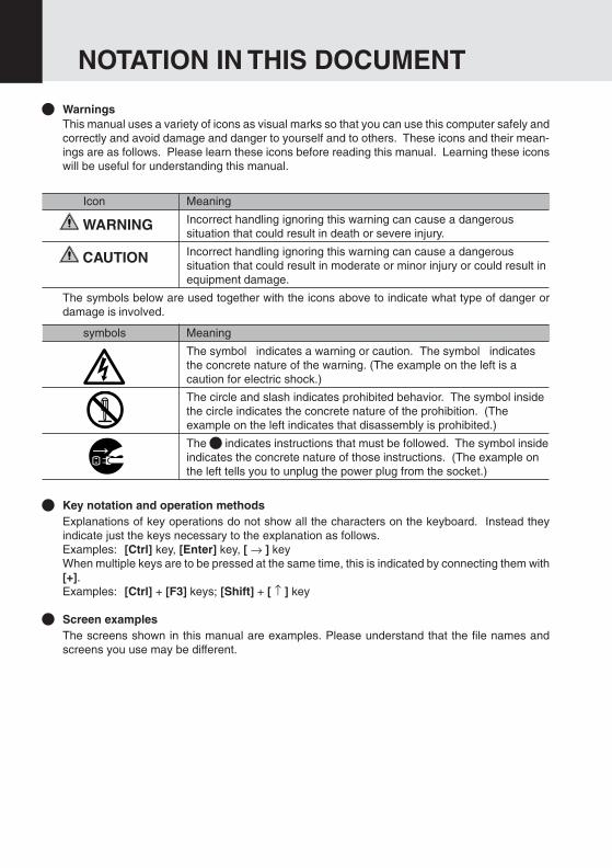
WarningsThis manual uses a variety of icons as visual marks so that you can use this computer safely andcorrectly and avoid damage and danger to yourself and to others. These icons and their mean-ings are as follows. Please learn these icons before reading this manual. Learning these iconswill be useful for understanding this manual.
Icon Meaning
Incorrect handling ignoring this warning can cause a dangeroussituation that could result in death or severe injury.
Incorrect handling ignoring this warning can cause a dangeroussituation that could result in moderate or minor injury or could result inequipment damage.
The symbols below are used together with the icons above to indicate what type of danger ordamage is involved.
symbols Meaning
The symbol indicates a warning or caution. The symbol indicatesthe concrete nature of the warning. (The example on the left is acaution for electric shock.)
The circle and slash indicates prohibited behavior. The symbol insidethe circle indicates the concrete nature of the prohibition. (Theexample on the left indicates that disassembly is prohibited.)
The indicates instructions that must be followed. The symbol insideindicates the concrete nature of those instructions. (The example onthe left tells you to unplug the power plug from the socket.)
Key notation and operation methodsExplanations of key operations do not show all the characters on the keyboard. Instead theyindicate just the keys necessary to the explanation as follows.Examples: [Ctrl] key, [Enter] key, [ → ] keyWhen multiple keys are to be pressed at the same time, this is indicated by connecting them with[+].Examples: [Ctrl] + [F3] keys; [Shift] + [ ↑ ] key
Screen examplesThe screens shown in this manual are examples. Please understand that the file names andscreens you use may be different.
NOTATION IN THIS DOCUMENT
WARNING
CAUTION
Bis Content 01/11/1999, 15:102

Critical Points
Column
dir c:
Notation in textHere is what symbols in text mean.
Symbol Meaning
Critical Point Indicates a point necessary for correctly operating thehardware or software.
Column Gives the meaning and brief explanation of a term.
→ Indicates the page to see elsewhere in this manual.
Command input (key input)Within the text of this manual, command input (giving commands to the computer by pressingkeys) is indicated as follows.
Example:↑
In the position indicated in the example above by the ↑, the space left between the charactersindicates that a space needs to be left in the entry by pressing the space bar (the long key withnothing written on it at the center of the front of the keyboard). Commands are written in thismanual as lowercase latin letters, but uppercase letters may be used.
Product namesThe following product names are abbreviated as follows in this manual.
“Microsoft® Windows® 98 operating system” is written as “Windows 98”.“Microsoft® MS-DOS® operating system Version 6.2/V” is written as “MS-DOS”.“Microsoft® Windows® operating system Version 3.1” is written as “Windows 3.1”.“Microsoft® Windows NT® Workstation operating system Version 4.0” is written as“Windows NT 4.0”.“Microsoft® Windows NT® Workstation operating system Version 3.51” is written as“Windows NT 3.51”.“Windows NT 4.0” and “Windows NT 3.51” are both written as Windows NT.“LifeBook” is written as “this computer” or “the computer main unit”.
Bis Content 01/11/1999, 15:103
SECTION 1
This section explains basic operations and basic items for using this computer, including thenames of the parts and their functions, Flat point operation methods, floppy disk unit handing,and battery operation.
SECTION 2
This section explains installation of options for this computer.
SECTION 3
This section explains the BIOS setup program, which is necessary for setting thedate and time and power conservation mode. This section also explains how toset the password for protecting data in this computer.
SECTION 4
This section explains what to do when trouble occurs with this computer and when messages aredisplayed. Read this section as the necessity arises.
Configuration of this Manual
SE
CT
ION
1S
EC
TIO
N 2
SE
CT
ION
3S
EC
TIO
N 4
Bis Content 01/11/1999, 15:104
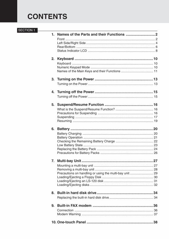
1. Names of the Parts and their Functions .............................2Front .................................................................................................... 2Left Side/Right Side ............................................................................. 4Rear/Bottom ........................................................................................ 6Status Indicator LCD ........................................................................... 8
2. Keyboard ..............................................................................10Keyboard ........................................................................................... 10Numeric Keypad Mode ...................................................................... 10Names of the Main Keys and their Functions .................................... 11
3. Turning on the Power ..........................................................13Turning on the Power ......................................................................... 13
4. Turning off the Power ..........................................................15Turning off the Power ......................................................................... 15
5. Suspend/Resume Function ................................................16What is the Suspend/Resume Function? .......................................... 16Precautions for Suspending .............................................................. 16Suspending ....................................................................................... 17Resuming .......................................................................................... 19
6. Battery ..................................................................................20Battery Charging ............................................................................... 20Battery Operation .............................................................................. 21Checking the Remaining Battery Charge .......................................... 22Low Battery State .............................................................................. 23Replacing the Battery Pack ............................................................... 24Precautions for Battery Packs ........................................................... 26
7. Multi-bay Unit .......................................................................27Mounting a multi-bay unit .................................................................. 27Removing a multi-bay unit ................................................................. 28Precautions on handling or using the multi-bay unit .......................... 29Loading/Ejecting a Floppy Disk ......................................................... 30Loading/Ejecting an LS-120 disk ....................................................... 31Loading/Ejecting disks ....................................................................... 32
8. Built-in hard disk drive........................................................34Replacing the built-in hard disk drive ................................................. 34
9. Built-in FAX modem ............................................................36Connection ........................................................................................ 36Modem Warning ................................................................................ 37
10. One-touch Panel ..................................................................38
CONTENTS
SECTION 1
Bis Content 01/11/1999, 15:105
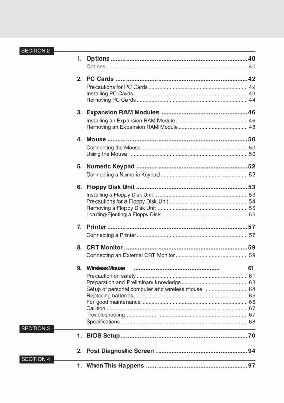
1. Options .................................................................................40Options .............................................................................................. 40
2. PC Cards ..............................................................................42Precautions for PC Cards .................................................................. 42Installing PC Cards ............................................................................ 43Removing PC Cards .......................................................................... 44
3. Expansion RAM Modules ...................................................46Installing an Expansion RAM Module ................................................ 46Removing an Expansion RAM Module .............................................. 48
4. Mouse ...................................................................................50Connecting the Mouse ...................................................................... 50Using the Mouse ............................................................................... 50
5. Numeric Keypad ..................................................................52Connecting a Numeric Keypad .......................................................... 52
6. Floppy Disk Unit ..................................................................53Installing a Floppy Disk Unit .............................................................. 53Precautions for a Floppy Disk Unit .................................................... 54Removing a Floppy Disk Unit ............................................................ 55Loading/Ejecting a Floppy Disk ......................................................... 56
7. Printer ...................................................................................57Connecting a Printer .......................................................................... 57
8. CRT Monitor .........................................................................59Connecting an External CRT Monitor ................................................ 59
9. Wireless Mouse ................................................... 61Precaution on safety .......................................................................... 61Preparation and Preliminary knowledge ............................................ 63Setup of personal computer and wireless mouse ............................. 64Replacing batteries ............................................................................ 65For good maintenance ....................................................................... 66Caution .............................................................................................. 67Troubleshooting ................................................................................. 67Specifications .................................................................................... 68
SECTION 2
SECTION 3
SECTION 4
1. BIOS Setup ...........................................................................70
2. Post Diagnostic Screen ......................................................94
1. When This Happens ............................................................97
Bis Content 01/11/1999, 15:106

1111111111
SECTIONSECTIONSECTIONSECTIONSECTIONSECTIONSECTIONSECTIONSECTIONSECTION
This section explains basic operations and basicitems for using this computer, including the namesof the parts and their functions, Flat point operationmethods, floppy disk unit handing, and batteryoperation.
SE
CT
ION
1
Bis Sec 1(01—09) 01/11/1999, 15:101
2
SECTION 1
1. Names of the Parts and their Functions
Front
11
12
14
15
13
10
2
9
1
3
4
5
6
7
8
Bis Sec 1(01—09) 01/11/1999, 15:102

3
SE
CT
ION
1
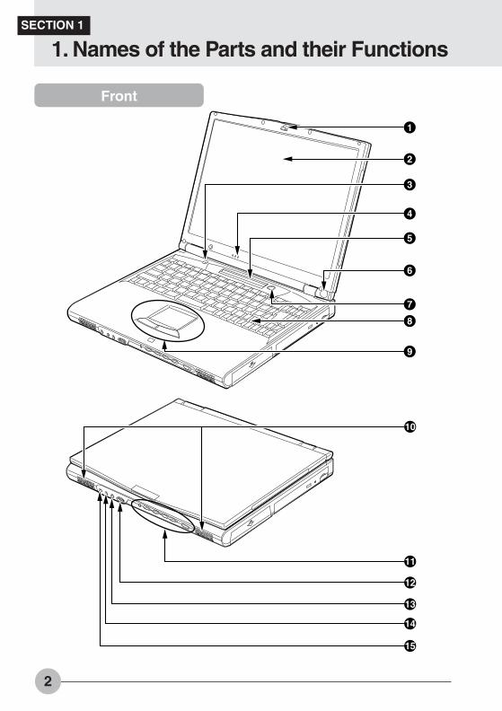
1 LatchThis is pulled to release the lock when the LCD display panel is opened.
2 LCD Display PanelDisplays text, graphics, etc.
3 Closed Cover SwitchThis switch puts out the backlighting when the LCD display panel is closed.
4 Condenser MicrophoneAllows sound recording.
5 Status Indicator LCDDisplays the status of the computer main unit. See “Status Indicator LCD”.
6 Wireless mouse photocell (only for models with a wireless mouse)Receives infrared signals from the wireless mouse.
7 Suspend/Resume ButtonThis button starts up/suspends/resumes the computer main unit. From here on, it is written asSUS/RES button.
8 KeyboardKeys are pressed to give commands to the computer main unit.
9 Pointing DeviceThis moves the mouse pointer.
! SpeakerOutputs the stereo sound of the computer main unit.
" One-touch panelThe buttons on the panel are used to launch application software.
# Volume controlAdjusts the sound volume. Turning it left lowers the volume; turning it right raises it.
$ Microphone jackCan be connected with a commercially available microphone.
% Line In jackTerminal for audio input.
& Headphone jackFor connecting commercially available headphones.
Critical PointIf the volume is raised too high when using a microphone, howling may occur between thespeaker and the microphone.
Critical PointThings that can be fitted to the headphone jack- Headphones, earphones, amplifier-installed external speakers (mini-plug with 3.5mm outer
diameter. However you may not be able to fit them because of the shape, so check beforeinserting.)
Bis Sec 1(01—09) 01/11/1999, 15:103
4
Left Side/Right Side
16
17
18
19
20
21
22
23
24
25
26
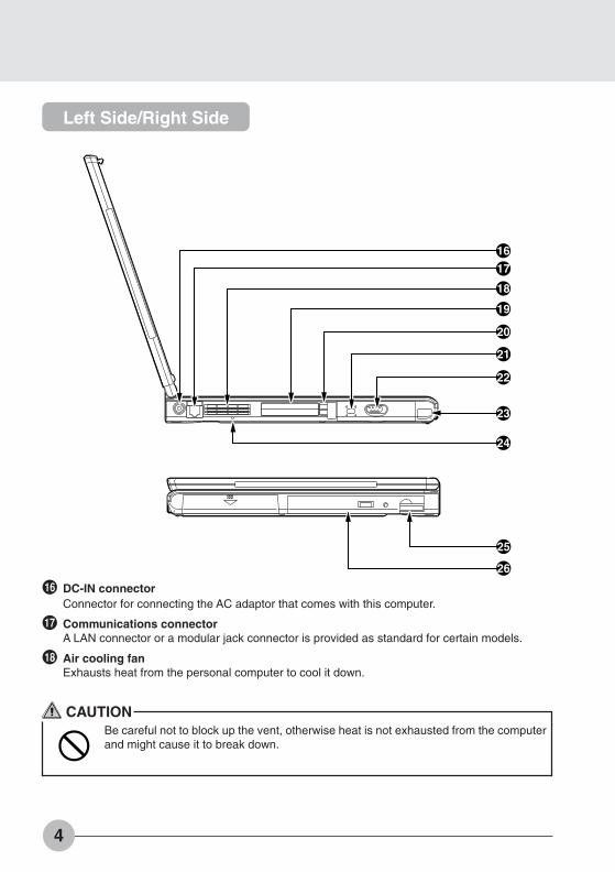
( DC-IN connectorConnector for connecting the AC adaptor that comes with this computer.
) Communications connectorA LAN connector or a modular jack connector is provided as standard for certain models.
~ Air cooling fanExhausts heat from the personal computer to cool it down.
CAUTIONBe careful not to block up the vent, otherwise heat is not exhausted from the computerand might cause it to break down.
Bis Sec 1(01—09) 01/11/1999, 15:104
5
SE
CT
ION
1
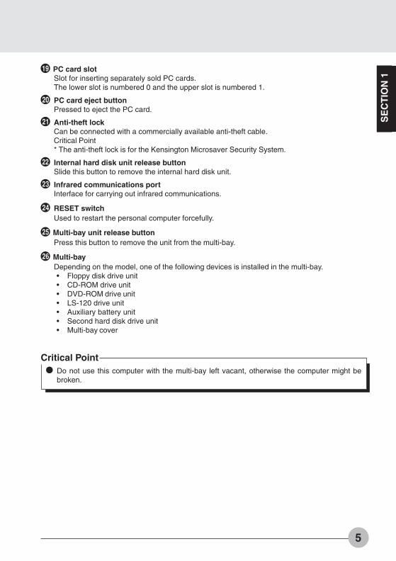
+ PC card slotSlot for inserting separately sold PC cards.The lower slot is numbered 0 and the upper slot is numbered 1.
, PC card eject buttonPressed to eject the PC card.
- Anti-theft lockCan be connected with a commercially available anti-theft cable.Critical Point* The anti-theft lock is for the Kensington Microsaver Security System.
. Internal hard disk unit release buttonSlide this button to remove the internal hard disk unit.
/ Infrared communications portInterface for carrying out infrared communications.
: RESET switchUsed to restart the personal computer forcefully.
; Multi-bay unit release buttonPress this button to remove the unit from the multi-bay.
< Multi-bayDepending on the model, one of the following devices is installed in the multi-bay.• Floppy disk drive unit• CD-ROM drive unit• DVD-ROM drive unit• LS-120 drive unit• Auxiliary battery unit• Second hard disk drive unit• Multi-bay cover
Critical PointDo not use this computer with the multi-bay left vacant, otherwise the computer might bebroken.
Bis Sec 1(01—09) 01/11/1999, 15:105
6
31
30
29
28
27
32
33
35
34
36
Rear/Bottom
Bis Sec 1(01—09) 01/11/1999, 15:106
7
SE
CT
ION
1
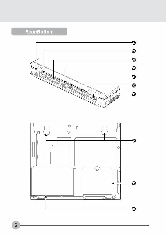
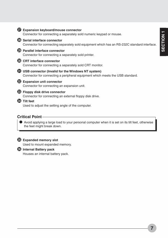
= Expansion keyboard/mouse connectorConnector for connecting a separately sold numeric keypad or mouse.
> Serial interface connectorConnector for connecting separately sold equipment which has an RS-232C standard interface.
? Parallel interface connectorConnector for connecting a separately sold printer.
@ CRT interface connectorConnector for connecting a separately sold CRT monitor.
[ USB connector (Invalid for the Windows NT system)Connector for connecting a peripheral equipment which meets the USB standard.
\ Expansion unit connectorConnector for connecting an expansion unit.
] Floppy disk drive connectorConnector for connecting an external floppy disk drive.
^ Tilt feetUsed to adjust the setting angle of the computer.
_ Expanded memory slotUsed to mount expanded memory.
{ Internal Battery packHouses an internal battery pack.
Critical PointAvoid applying a large load to your personal computer when it is set on its tilt feet, otherwisethe feet might break down.
Bis Sec 1(01—09) 01/11/1999, 15:107

8
11 2 A1
1 2 11 123 5
2
8 9 1076
Status Indicator LCD
1 SUS/RES indicator ( )When this computer is operating, this indicator lights up; when the computer is in suspend mode,this indicator flashes.
2 AC adaptor indicator ( )Lights up when the power is being supplied from the AC adaptor.
3 Battery pack mounting indicators (1, 2, )Lights up when the battery pack is mounted. The number 1 refers to the built-in battery pack andthe number 2 refers to the expanded battery pack.
4 Battery charging indicator ( )Lights up when the battery is charging; flashes when the battery is too hot or cold to charge.
5 Remaining battery charge indicator ( )Displays the amount of charge remaining in the corresponding battery.
6 CD-ROM drive access indicator ( )Lights up while data is being read from the CD-ROM or the DVD-ROM.
7 Hard disk access indicator ( )Lights up while the internal hard disk or the 2nd hard disk is being accessed.
8 Floppy disk access indicator ( )Lights up while data is being read/written on the floppy disk or the LS-120 disk.
9 PC card access indicator ( 1 2 )Lights up while the PC card in the corresponding PC card slot is being accessed.
Bis Sec 1(01—09) 01/11/1999, 15:108

9
SE
CT
ION
1! Num Lock indicator ( 1 )Lights up when [Num Lk] key is pressed to put the keyboard into numeric keypad mode.
" Caps Lock indicator ( A )Lights up when [Shift] + [Caps lock] keys are pressed to put the keyboard into CAPS mode.
# Scroll Lock indicator ( )Lights up or goes out each time the [Fn] + [Scr Lk] keys are pressed.
Critical PointIf you turn off the main switch or operate the SUS/RES button while the hard disk accessindicator or floppy disk access indicator is lit, the data being accessed may be destroyed.When the main switch is switched off, all the indicators other than charging go off. However,the AC adaptor lamp comes on regardless of the status indicator lamp when power is beingsupplied.When you use Windows 98, if the CD automatic insertion function is enabled, the systemperiodically checks for a CD. Therefore, the CD-ROM drive access indicator on the statusindicator LCD lights up periodically.
Bis Sec 1(01—09) 01/11/1999, 15:109
10
SECTION 1
2. Keyboard
Keyboard
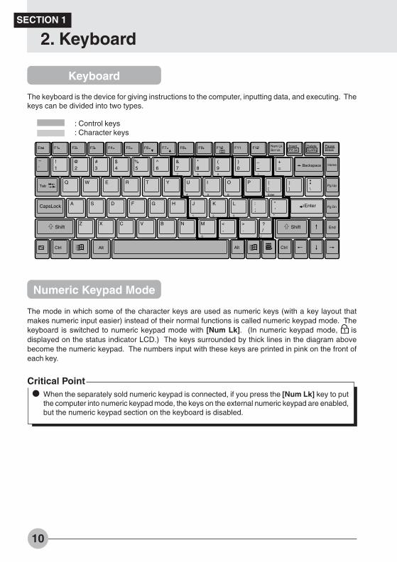
The keyboard is the device for giving instructions to the computer, inputting data, and executing. Thekeys can be divided into two types.
The mode in which some of the character keys are used as numeric keys (with a key layout thatmakes numeric input easier) instead of their normal functions is called numeric keypad mode. Thekeyboard is switched to numeric keypad mode with [Num Lk]. (In numeric keypad mode, 1 isdisplayed on the status indicator LCD.) The keys surrounded by thick lines in the diagram abovebecome the numeric keypad. The numbers input with these keys are printed in pink on the front ofeach key.
Fn Ctrl Alt Alt Ctrl
F1Esc F2 F3 F4 F5 F6 F7 F8 F9 F10 F11 F12 Num LkScr Lk
InsertPrt Sc
DeleteSysRq
PauseBreak
!1 2
@ #3
$4
%5
^6 7
& *8
(9 0
) _
-+=
Backspace Home
\Tab
Q W E R T Y U I O P
7 8 9
4 5 6
[
{
]
}
EnterA S D F G H J K L "
1 2 3 *
Pg Dn
Shift ShiftZ X C V B N M <
,>.
0
/?
End
/
-
Enter
':;
CapsLock
Pg Up
: Control keys: Character keys
Numeric Keypad Mode
Critical PointWhen the separately sold numeric keypad is connected, if you press the [Num Lk] key to putthe computer into numeric keypad mode, the keys on the external numeric keypad are enabled,but the numeric keypad section on the keyboard is disabled.
Bis Sec 1(10-21) 01/11/1999, 15:1010
11
SE
CT
ION
1Names of the Main Keys and their Functions
[Esc] (escape) keyThe usage is determined by the application software. It is often used to return to theprevious operation.
[F1]-[F12] (function) keysThe usage depends on the application software.
[Fn] keyA key unique to this computer; it has the following functions.
[Fn] + [F3] This switches ON/OFF of the speaker.When a beep sounds is heard, the speaker is on. When no beep sound,the beep is turned off.
[Fn] + [F5] This selects whether or not to use the entire LCD screen for display intext mode.
[Fn] + [F6] Turns down the backlight of the LCD.[Fn] + [F7] Turns up the backlight of the LCD.
Critical PointLuminance of the backlight of the LCD can be turned up (with [Fn]+[F7] keys) or turned down(with [Fn]+[F6] keys) in three degrees.
[Fn] + [F10] Rotates among the three display options: LCD only, CRT only, both LCDand CRT.
[Space] keyInputs a single space character.(This is the long key with nothing written on it at the center of the front of the keyboard.)
[↑] [↓] [←] [→] (cursor) keysMove the cursor.
[Enter] keyAlso called the return key or the line feed key. This key inputs line feeds and executescommand.
[Ctrl] keyUsed in combination with other keys; its functions depend on the application software.
[Shift] keyUsed in combination with other keys.
[Alt] keyUsed in combination with other keys; its functions depend on the application software.
Bis Sec 1(10-21) 01/11/1999, 15:1011

12
[Caps Lock] keyTo lock the keyboard into caps mode, press this key together with the [Shift] key.Pressing this key again ends caps mode.
[Num Lk] (numerical lock) keyPress this key to put the computer into numeric keypad mode.
[Scr Lk] (scroll lock) keyIts functions depend on the application software. Press this key together with the [Fn]key.
[Print Screen] keyPress this key to make a hard copy of the screen.
[Pause] keyPress this key to pause the screen display.
[Break] keyIts functions depend on the application software.
[Insert] keyPress this key to insert a new character between characters. The new characters areentered at the cursor position.
[Delete] keyPress this key to delete a character. Pressing the Delete key and the Ctrl and Alt keys atthe same time resets this computer.
[Home] keyPress this key to move the cursor directly to the head of the row or the head of thedocument.
[End] keyPress this key to move the cursor directly to the end of the row or the end of thedocument.
[Page Up] keyPress this key to switch to the previous screen.
[Page Down] keyPress this key to switch to the next screen.
[Back Space] keyPress this key to delete the character to the left of the cursor position.
[Sys Rq] (system request) keyWhen this key is supported by the application software, this key is used for suchfunctions as resetting the keyboard. Press this key together with the Alt key.
[ ] (Windows) keyPress this key to display the Start menu.
[ ] (Application)Press this key to display the shortcut menu for the selected item. This key has the samerole as the mouse right click.
Bis Sec 1(10-21) 01/11/1999, 15:1012

13
SE
CT
ION
1
SECTION 1
3. Turning on the Power
Turning on the power
This item explains the normal way to turn the computer main unit power on and off.
1 Connect the AC adaptor. 2 Open the LCD display panel.
Latch
AC adaptor
Pull the latch to release the lock, then lift thedisplay panel with your hand.
3 Press the SUS/RES button.
SUS/RES button.
Power is supplied from the AC adaptor or thebattery, the power comes on, and the POSTstarts. Also, the etc. on the status indicatorLCD are displayed.
Bis Sec 1(10-21) 01/11/1999, 15:1013

14
Critical PointDo not carry this computer around or subject it to shock or vibration with the power on. Thesecan result in breakdown.
ColumnPOST is the abbreviation for POWER ON SELF TEST, which is a self-diagnostic test thatchecks for abnormalities within the computer. This test is automatically carried out when thepower is switched on for this computer. If the power is switched off during the POST, an errormessage is displayed the next time the computer is started up. Do not cut off the powerduring the POST.
Bis Sec 1(10-21) 01/11/1999, 15:1014

15
SE
CT
ION
1
SECTION 1
4. Turning off the Power
This item explains how to turn off the power.
Turning off the Power
Critical PointDo not turn back on the computer immediately after turning it off, but wait for 10 seconds orso.
When the computer is not used for a long time, unload the floppy disk and the CD-ROM fromthe computer before turning it off.
1 Click the Start button.The Start menu is displayed.
2 Click Shut Down.The following message is displayed.
3 Check that Shut down the computer is selected, then click Yes.The power is turned off.
Critical PointIf the personal computer won’t be used for a long time after this step, be sure to disconnectthe AC adaptor and to remove the battery pack from it.
If “Restart” or “Restart computer”is selected on the dialog box that appears as a result of thesteps 2, the personal computer will be restarted. “Restart” means that the personal computererases all data saved in the memory once and again reads the program of the operatingsystem from the floppy disk or hard disk into it.
Bis Sec 1(10-21) 01/11/1999, 15:1015
16
SECTION 1
5. Suspend/Resume Function
What Is the Suspend/Resume Function?
When this computer is suspended with the SUS/RES button, the suspend/resume function retainsthe programs and data in memory as is so that you can resume operations immediately the next timeyou press the SUS/RES button.
Precautions for Suspending
Pay attention to the following points when using the suspend function.
When the computer is connected to a network using a LAN or modem and when the peripheralequipment is expanded with a PC card, you may not be able to use the suspend/resumefunction. When you have expanded functions with a PC card, also check the manual for thecards you are using.
Do not operate the SUS/RES button when using Windows NT.
In the following cases, do not use the suspend function, but turn off the computer.• When this computer is unused for a long period
When this computer will be unused longer than the effective period (about one day maximum)for battery power for suspend mode, save all data, close Windows 98, then turn off thecomputer.
• When installing or removing optionsThere are some options that can be installed without turning off the computer. SeeSECTION 2 of this manual and the manual that comes with the option product.
Bis Sec 1(10-21) 01/11/1999, 15:1016

17
SE
CT
ION
1Suspending
There are three ways to suspend this computer, using the SUS/RES buton, Closed Cover switch andfor Windows 98, using the Shut Down dialog.
Using the SUS/RES button
1 Suspending
Check that and are out. Whenyou press the SUS/RES button, flashes and the computer goes intosuspend mode.
SUS/RES button
Critical PointWhich of the two destinations suspending saves the data in the computer to depends on theBIOS setup Power menu setting as follows.
System RAM:When “Suspend To RAM” is set with the BIOS setup Power menu “Suspend Mode”item, the data is saved to system RAM. Power for the system RAM is supplied fromthe AC power supply if the AC adaptor is connected or from the battery if the ACadaptor is not connected.
Save to Disk area:If “Suspend to Disk” is set with the BIOS setup Power menu “Suspend Mode” item, thedata is written to the Save to Disk area on the hard disk.
If you hold down the Fn key while pressing the SUS/RES button, the data is saved to the harddisk regardless of the Power menu setting.
Bis Sec 1(10-21) 01/11/1999, 15:1017
18
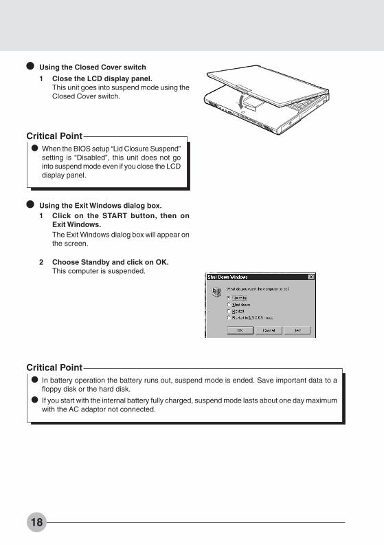
Using the Closed Cover switch
1 Close the LCD display panel.This unit goes into suspend mode using theClosed Cover switch.
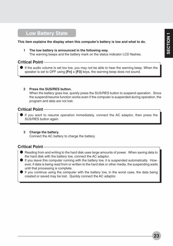
Using the Exit Windows dialog box.1 Click on the START button, then on
Exit Windows.The Exit Windows dialog box will appear onthe screen.
2 Choose Standby and click on OK.This computer is suspended.
Critical PointIn battery operation the battery runs out, suspend mode is ended. Save important data to afloppy disk or the hard disk.
If you start with the internal battery fully charged, suspend mode lasts about one day maximumwith the AC adaptor not connected.
Critical PointWhen the BIOS setup “Lid Closure Suspend”setting is “Disabled”, this unit does not gointo suspend mode even if you close the LCDdisplay panel.
Bis Sec 1(10-21) 01/11/1999, 15:1018

19
SE
CT
ION
1Resuming
You can make the computer resume the current application program, using either the SUS/RESbutton or the closed cover switch.
Critical PointImmediately after putting it into the Suspend mode, do not make the computer resume theprogram but wait for 10 seconds or so.
Using the SUS/RES button1 Press the SUS/RES button.
Pressing the SUS/RES button will causethe indicator on the status displaypanel to stop blinking and light uppermanently, and will bring the computerinto operation.
SUS/RES
Critical PointDo not hold down the SUS/RES button for more than 4 seconds, otherwise the computer willbe turned off.
Using the closed cover switch1 Open the LCD display.
Opening the LCD display will turn on theCover Close switch and make thecomputer resume the current program.
Critical PointThe Resume function does not operate if Lid Open Resume in the BIOS Setup dialog box isnot selected.
Latch
Bis Sec 1(10-21) 01/11/1999, 15:1019

20
SECTION 1
6. Battery
Battery ChargingFor portability, this computer can operate either from the AC adaptor or from its battery. Thisitem explains how to charge the battery.
1 Connect the AC adaptor.
AC adaptor
2 1 is displayed.
1
During charging, 1 is displayed on thestatus indicator LCD and the remaining batterycharge is displayed.
Relationship between computer modes and battery charging time
Main switch SUS/RES button Computer mode Charging mode Charging time
On Resume Operating mode Standard charging About XX hours
Suspend Suspend mode Quick charge About XX hours
Off ___ Stopped
Critical PointWhen the battery charge indicator goes out and status of the remaining battery powerindicator on the left side changes from blinking to continuous lighting ,chargingthe battery is complete. Spend considerable hours for charging the battery so that it is fullycharged.
The battery capacity falls if the ambient temperature is too low or too high.
Just after use of the battery, charging it may result in failure because the battery temperaturehas risen and the battery protection function is activated. In such the case, leave the batteryin the charging status and charging will start a while later with drop of the battery temperature.
Bis Sec 1(10-21) 01/11/1999, 15:1020

21
SE
CT
ION
1Battery Operation
This item explains operation with the battery.
1 Disconnect the AC adaptor and pressthe SUS/RES button.
SUS/RES button.
Critical PointWhen the ambient temperature is lower, the battery operating time is reduced.
With this computer, the battery operating time depends on the conditions under which thebattery is used. However, the operating time of a new, fully-charged battery is about XX to XXhours.
Conditions:Main unit only, full charge, with power management on. (The yardstick for operating time depends on the conditions of use.)
Bis Sec 1(10-21) 01/11/1999, 15:1021

22
Checking the Remaining Battery ChargeThis computer indicates the amount of battery charge remaining with the remaining batterycharge indicator on the status indicator LCD.
Remaining battery charge indicator
Battery abnormality indicator
Critical Point
When is displayed, take out the battery pack and re-install it. If this display stillremains, the battery pack is abnormal, so replace it.
Indicates battery charge level of about 76% to about 100%
Indicates battery charge level of about 51% to about 75%
Indicates battery charge level of about 26% to about 50%
Indicates battery charge level of about 16% to about 25%
Indicates the low battery state (battery charge level of about 15% or lower). A beepgoes off and _ flashes.
Indicates that the battery has run out (0% charge level).
Indicates that the battery can not be charged normally.
Bis Sec 1(22-33) 01/11/1999, 15:1022
SE
CT
ION
1
23
Low Battery State
This item explains the display when this computer’s battery is low and what to do.
1 The low battery is announced in the following way.The warning beeps and the battery mark on the status indicator LCD flashes.
Critical PointIf the audio volume is set too low, you may not be able to hear the warning beep. When thespeaker is set to OFF using [Fn] + [F3] keys, the warning beep does not sound.
2 Press the SUS/RES button.When the battery goes low, quickly press the SUS/RES button to suspend operation. Sincethe suspend/resume function works even if the computer is suspended during operation, theprogram and data are not lost.
Critical PointIf you want to resume operation immediately, connect the AC adaptor, then press theSUS/RES button again.
3 Charge the battery.Connect the AC battery to charge the battery.
Critical PointReading from and writing to the hard disk uses large amounts of power. When saving data tothe hard disk with the battery low, connect the AC adaptor.If you leave this computer running with the battery low, it is suspended automatically. How-ever, if data is being read from or written to the hard disk or other media, the suspending waitsuntil that processing is complete.If you continue using the computer with the battery low, in the worst case, the data beingcreated or saved may be lost. Quickly connect the AC adaptor.
Bis Sec 1(22-33) 01/11/1999, 15:1023
24
Replacing the Battery Pack
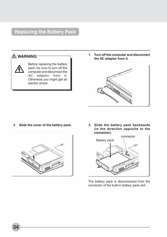
1 Turn off the computer and disconnectthe AC adaptor from it.
2 Slide the cover of the battery pack.
The battery pack is disconnected from theconnector of the built-in battery pack slot.
connectorBattery pack
WARNING
Before replacing the batterypack, be sure to turn off thecomputer and disconnect theAC adaptor from it.Otherwise you might get anelectric shock.
3 Slide the battery pack backwards(in the direction opposite to theconnector).
Bis Sec 1(22-33) 01/11/1999, 15:1024
SE
CT
ION
1
25
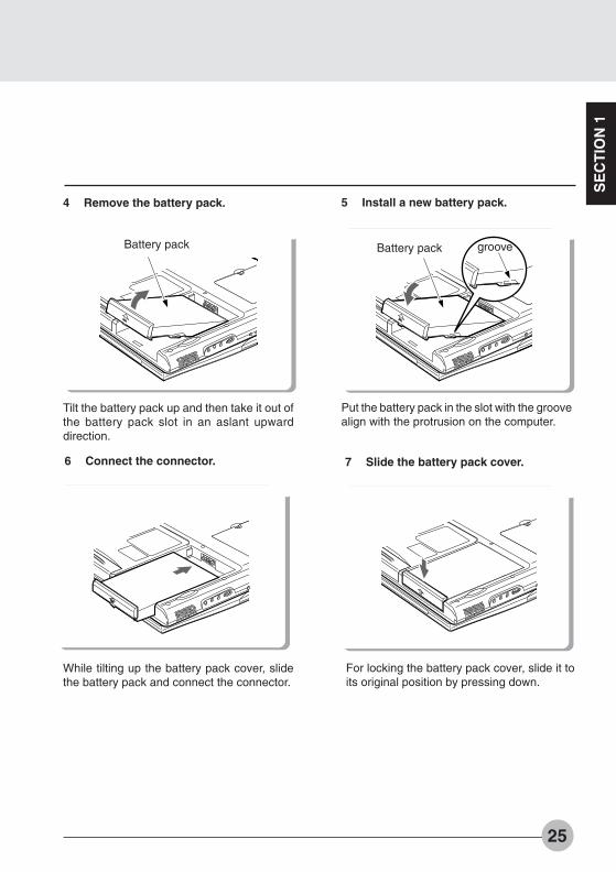
4 Remove the battery pack.
Battery pack
Tilt the battery pack up and then take it out ofthe battery pack slot in an aslant upwarddirection.
5 Install a new battery pack.
Put the battery pack in the slot with the groovealign with the protrusion on the computer.
grooveBattery pack
6 Connect the connector.
While tilting up the battery pack cover, slidethe battery pack and connect the connector.
7 Slide the battery pack cover.
For locking the battery pack cover, slide it toits original position by pressing down.
Bis Sec 1(22-33) 01/11/1999, 15:1025
26
Precautions for Battery Pack
WARNING
The battery pack is extremely delicate products. When installing or removing one, donot drop it or subject it to strong shocks. If this should happen, do not use that batterypack in the interest of safely, because there is a risk of electric shock or malfunction.
DischargeAfter you charge the battery pack, even if you store it without using it, over about 1 month it willnaturally discharge.
Service life• The battery pack is a consumption item. After you use it for a long time, its charging capacitydrops.
• Replace the battery after about 300 to 500 charge/discharge cycles.• When the battery operating time becomes extremely short, the battery has reached the endof its service life.
To extend the battery operating timeUse the BIOS setup Power menu.
Conditions under which the battery operating time becomes shorter• Using in cold or hot location
The battery operating time is influenced by the environmental temperature and the batteryoperating time can be shorter at low temperature (5°C) then at high temperature (35°C). Also,high temperatures not only lower the charging efficiency, but are also a cause of battery packdeterioration.
• When the battery charging capacity drops When the battery pack has been used for a long time, its charging capacity drops. In thiscase, replace it with a new battery pack.
Use the AC adaptor in the following cases• When using the hard disk or CD-ROM frequently• When using a LAN or a modem
Bis Sec 1(22-33) 01/11/1999, 15:1026

SE
CT
ION
1
27
Mounting a multi-bay unit
SECTION 1
7. Multi-bay Unit
This item explains how to mount the multi-bay unit.
1 Turn off the computer and disconnectthe AC adaptor from it.
2 Pull out the multi-bay unit releasebutton.
Remove the multi-bay unit and make sure thatthe multi-bay unit release button is pulled out.
Multi-bayunit releasebutton
3 Mount a multi-bay unit.
Push in the unit as far as it will go with itsconnector pointing inward.
Multi-bay unit
WARNING
Be sure to turn off yourpersonal computer anddisconnect the AC adaptorfrom it before mounting themulti-bay unit, otherwise youmight get an electric shock.
Bis Sec 1(22-33) 01/11/1999, 15:1027

28
Removing a multi-bay unit
This item explains how to remove a multi-bay unit.
WARNING
Be sure to turn off yourpersonal computer anddisconnect the AC adaptorfrom it before removing theunit from the multi-bay,otherwise you might get anelectric shock.
1 Turn off the computer and disconnectthe AC adaptor from it.
2 Pull out the multi-bay unit releasebutton.
Pull out the multi-bay unit release button.
Multi-bay unitrelease button
3 Remove the multi-bay unit.
Press the multi-bay unit release button toremove the unit.
Multi-bay unitrelease button
Bis Sec 1(22-33) 01/11/1999, 15:1028

SE
CT
ION
1
29
Precautions on handling or using the multi-bay unit
To avoid possible trouble, always take the following precautions when handling or using themulti-bay unit.
Do not keep the multi-bay unit in a place where the temperature can fall extremely low, riseextremely high, or greatly change.
Do not place the multi-bay unit in a place exposed to direct sunlight nor get it near any heat-radiating apparatus.
Avoid keeping the multi-bay unit in a place subject to shocks or vibration.
Avoid using the multi-bay unit in a damp or dusty place.
Never use the multi-bay unit when a foreign matter, for example, liquid or a metal chip, hasgotten into it. If such a foreign matter gets into the multi-bay unit, consult the shop at whichyou bought it or the nearest Fujitsu service center.
When the multi-bay unit is dirty, do not use any volatile agent such as benzine or thinner toclean it. In such a case, wipe the dirt off with a soft dry cloth or a soft cloth moistened withwater or neutral cleaner thinned with water.
Never disassemble or take apart the multi-bay unit.
Avoid using or keeping the multi-bay unit near a magnet or an apparatus with a strong magneticfield.
Bis Sec 1(22-33) 01/11/1999, 15:1029
30
Loading/Ejecting a Floppy Disk
This item explains how to load and eject a floppy disk.
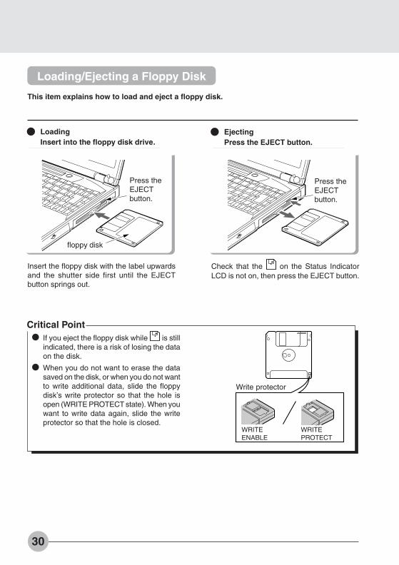
LoadingInsert into the floppy disk drive.
Insert the floppy disk with the label upwardsand the shutter side first until the EJECTbutton springs out.
EjectingPress the EJECT button.
Check that the on the Status IndicatorLCD is not on, then press the EJECT button.
Critical PointIf you eject the floppy disk while is stillindicated, there is a risk of losing the dataon the disk.
When you do not want to erase the datasaved on the disk, or when you do not wantto write additional data, slide the floppydisk’s write protector so that the hole isopen (WRITE PROTECT state). When youwant to write data again, slide the writeprotector so that the hole is closed.
Write protector
WRITEENABLE
WRITEPROTECT
floppy disk
Press theEJECTbutton.
Press theEJECTbutton.
Bis Sec 1(22-33) 01/11/1999, 15:1030

SE
CT
ION
1
31
Loading/Ejecting an LS-120 disk
The following explains how to load/eject an LS-120 disk in/from the LS-120 disk drive.* Available on certain models.
Loading an LS-120 diskInsert an LS-120 disk into the LS-120disk drive.
Insert an LS-120 disk into the LS-120 diskdrive with its label side up and the shutterfacing inwards.
EJECTbutton
Ejecting an LS-120 diskPress the EJECT button.
While confirming that the mark of thestatus indicator LCD is going out, press theEJECT button.
EJECTbutton
Critical PointSince the LS-120 disk drive of this personalcomputer locks the disk electronically, anyLS-120 disk can be ejected only when thepersonal computer is in the operating mode.If the LS-120 disk is not ejected for somereason, insert the tip of a paper clip or thelike into the EJECT jib hole. The disk will beejected.
If the LS-120 disk is ejected while the mark of the status indicator LCD is on, thedata stored in the disk may be broken.
To protect data stored in an LS-120 disk from erasure or to prevent additional data writing ona disk, slide the write protector knob of disk to make the square hole open (write inhibitstatus). To make the disk enabled for overwriting or additional writing, slide the write protectorknob again to shut the square hole (write enabled status).
Bis Sec 1(22-33) 01/11/1999, 15:1031

32
Loading/Ejecting disks
This item explains how to load/eject disks (CD-ROM/DVD-ROM, etc.).
1 Press the EJECT button.
The tray springs out slightly.
EJECT button.
2 Pull the tray out.
Pull the tray out gently.
3 Put in the Disk.
Place the Disk in the center of the tray withits label facing upwards.
Critical PointWhen drawing the tray out of the personalcomputer, fold the tilt foot on the side ofthe personal computer so as to flatten thebottom beforehand.
You can only install/eject a Disk when thecomputer main unit is in operating modebecause of the electronic lock of the CD-ROM/DVD-ROM drive.tween the speakerand the microphone.
Bis Sec 1(22-33) 01/11/1999, 15:1032

SE
CT
ION
1
33
4 Set the tray.
Push the tray in gently.
Critical PointIf the tray cannot be pushed to the innermost position, pull it out until it clicks and try to pushit deeply once more.
When ejecting a Disk, carry out the same procedure as for loading.
If for some reason the tray does not come out when you press the eject button, insertsomething like a ball-point pen into the hole to the right of the EJECT button on the right sideof the unit and pull out the tray.
Bis Sec 1(22-33) 01/11/1999, 15:1033
34
Replacing the built-in hard disk drive
SECTION 1
8. Built-in hard disk drive
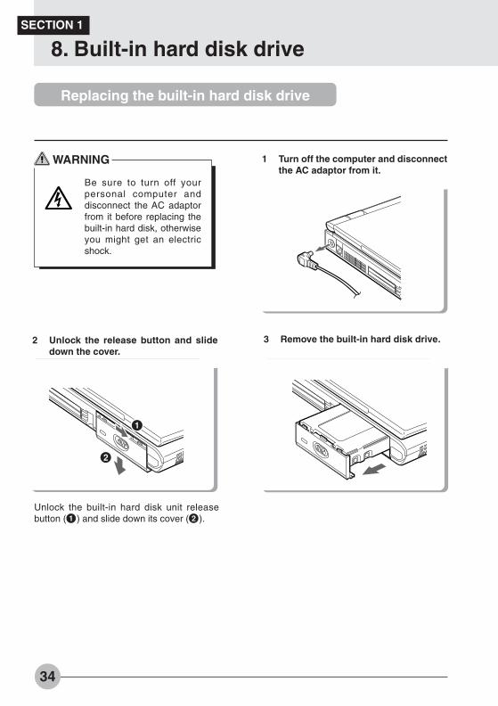
WARNING
Be sure to turn off yourpersonal computer anddisconnect the AC adaptorfrom it before replacing thebuilt-in hard disk, otherwiseyou might get an electricshock.
1 Turn off the computer and disconnectthe AC adaptor from it.
2 Unlock the release button and slidedown the cover.
Unlock the built-in hard disk unit releasebutton (1) and slide down its cover (2).
1
2
3 Remove the built-in hard disk drive.
Bis Sec 1(34-38) 01/11/1999, 15:1134

SE
CT
ION
1
35
4 Mount another built-in hard disk drive. 5 Lock the cover of the hard disk drive.
Slide up the cover to lock it.
Bis Sec 1(34-38) 01/11/1999, 15:1135

36
SECTION 1
9. Built-in FAX modem
Certain models have a built-in FAX modem as standard.
Connection
CAUTION
Do not touch the modular connector with your finger, otherwise you might get anelectric shock.
WARNING
Be sure to turn off your personal computer and disconnect the AC adaptor from itbefore connecting a modular cable to the computer, otherwise you might get anelectric shock.
When it thunders in the neighborhood, immediately turn off your personal computerand disconnect the AC adaptor and the modular cable from the computer, otherwiseyour computer might be struck and broken by lightening and thus cause a fire.
1. Turn off the computer and disconnect the AC adaptor from it.2. Using a modular cable, connect the computer to the telephone line.
Critical PointTo disconnect the modular cable from the connector, pull the jackwhile holding down the lug. Failure to do so might damage the jack,cable or connector.
Your computer consumes more electric energy when using thebuilt-in modem. When using the modem, therefore, it is advisableto use the AC adaptor to supply power to your computer.
Bis Sec 1(34-38) 01/11/1999, 15:1136
SE
CT
ION
1
37
Modem Warnings
CAUTIONThe internal modem is not intended for use with Digital PBX systems. Do not connectthe internal modem to a digital PBX as it may cause serious damage to the internalmodem or your entire notebook.Consult your PBX manufacturer’s documentation for details. Some hotels have digitalPBX systems.Be sure to find out BEFORE you connect your modem.
CAUTIONThe internal modem has a maximum speed of 56000bps by ITU-T V.90 standard. Itsmaximum speed of 53000bps is the highest allowed by FCC, and its actual connectionrate depends on the line conditions. The maximum speed is 33600bps at upload.
Bis Sec 1(34-38) 01/11/1999, 15:1137
38
SECTION 1
10. One-touch Panel
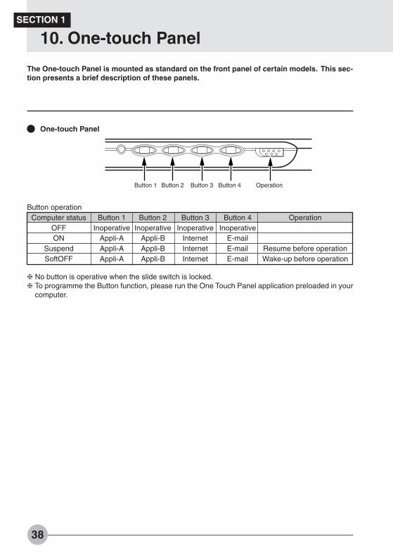
The One-touch Panel is mounted as standard on the front panel of certain models. This sec-tion presents a brief description of these panels.
One-touch Panel
Button operationComputer status Button 1 Button 2 Button 3 Button 4 Operation
OFF Inoperative Inoperative Inoperative InoperativeON Appli-A Appli-B Internet E-mail
Suspend Appli-A Appli-B Internet E-mail Resume before operationSoftOFF Appli-A Appli-B Internet E-mail Wake-up before operation
❈ No button is operative when the slide switch is locked.❈ To programme the Button function, please run the One Touch Panel application preloaded in your
computer.
Button 1 Button 2 Button 3 Button 4 Operation
Bis Sec 1(34-38) 01/11/1999, 15:1138
This section explains installation of options for thiscomputer.
SE
CT
ION
2
2222222222
SECTIONSECTIONSECTIONSECTIONSECTIONSECTIONSECTIONSECTIONSECTIONSECTION
Bis Sec 2 (39-49) 01/11/1999, 15:1139
40
SECTION 2
1. Options
Options
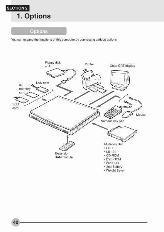
You can expand the functions of this computer by connecting various options.
Multi-bay Unit• FDD• LS-120• CD-ROM• DVD-ROM• 2nd HDD• 2nd Battery• Weight Saver
LAN card
Color CRT displayPrinter
Numeric key pad
Mouse
ExpansionRAM module
SCSIcard
ICmemorycard
Floppy diskunit
Bis Sec 2 (39-49) 01/11/1999, 15:1140
SE
CT
ION
2
41
WARNING
Only connect equipment recommended by Fujitsu.Connecting any other equipment can cause electric shock, fire, or breakdown.
Among the options are some that cannot be used with certain models.
CAUTION
Read this manual carefully and connect cables correctly. If you use this computer withcables connected incorrectly, this can cause breakdown of the computer main unitand of the peripheral equipment.
Bis Sec 2 (39-49) 01/11/1999, 15:1141

42
SECTION 2
2. PC Cards
Precautions for PC Cards
Observe the following points when using PC cards to prevent breakdown.
Do not place PC cards inhigh-temperature locations andlocations subject to directsunlight.
Do not subject PC cards tostrong shocks.
Avoid rubbing PC cards andbuilding up static electricity.
Do not place heavy objects ontop of PC cards.
Be careful to avoid spillingcoffee and other liquids on PCcards.
When storing a PC card, alwaysplace it in its special case.
Bis Sec 2 (39-49) 01/11/1999, 15:1142
SE
CT
ION
2
43
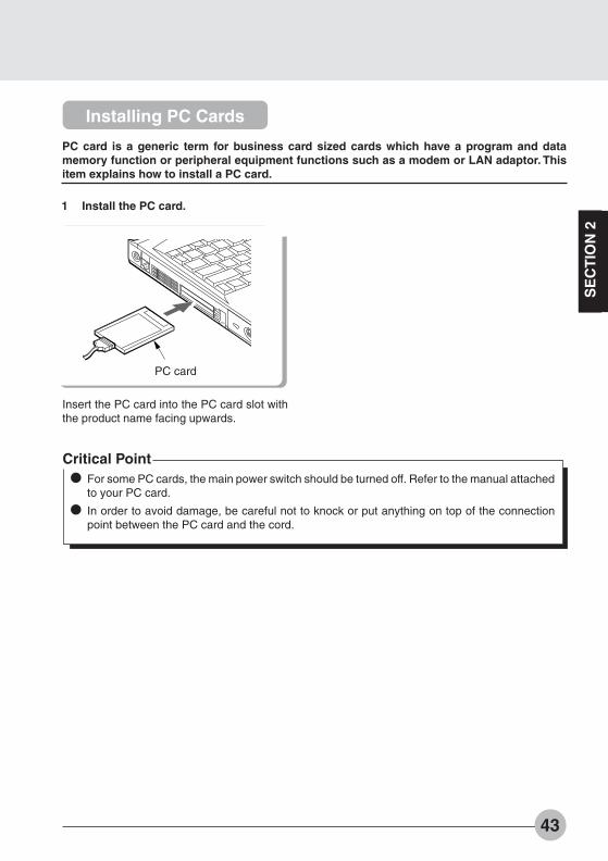
Installing PC Cards
PC card is a generic term for business card sized cards which have a program and datamemory function or peripheral equipment functions such as a modem or LAN adaptor. Thisitem explains how to install a PC card.
1 Install the PC card.
Insert the PC card into the PC card slot withthe product name facing upwards.
Critical PointFor some PC cards, the main power switch should be turned off. Refer to the manual attachedto your PC card.
In order to avoid damage, be careful not to knock or put anything on top of the connectionpoint between the PC card and the cord.
PC card
Bis Sec 2 (39-49) 01/11/1999, 15:1143

44
Removing PC Cards
This item explains how to remove a PC card.
1 Click the PC card indicator on the task bar.
A message is displayed for stopping the installed PC card.
2 Click the PC card to be removed.The PC card operations stop and the following screen is displayed.
Critical PointFor IC memory cards, the “This device cannot be removed” message may appear. If thismessage does appear, close Windows 98 and turn off the computer main unit power beforeremoving the IC memory card.
3 Click OK.
Bis Sec 2 (39-49) 01/11/1999, 15:1144
SE
CT
ION
2
45
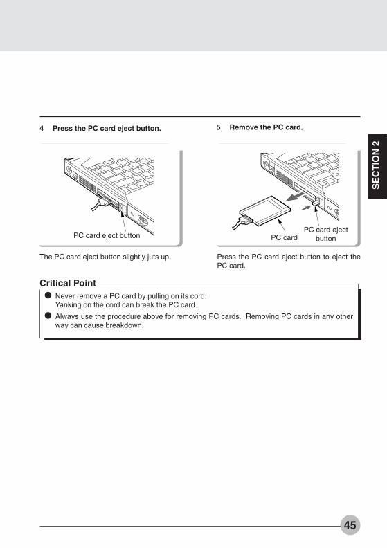
4 Press the PC card eject button.
The PC card eject button slightly juts up.
PC card eject button
5 Remove the PC card.
Press the PC card eject button to eject thePC card.
Critical PointNever remove a PC card by pulling on its cord.Yanking on the cord can break the PC card.
Always use the procedure above for removing PC cards. Removing PC cards in any otherway can cause breakdown.
PC card ejectbuttonPC card
Bis Sec 2 (39-49) 01/11/1999, 15:1145

46
SECTION 2
3. Expansion RAM Modules
WARNING
Always turn off thecomputer and disconnectthe AC adaptor wheninstalling an expansionRAM module in order toavoid electric shock.
Installing an Expansion RAM Module
This item explains how to install expansion RAM modules.
1 Turn off the computer and disconnectthe AC adaptor.
2 Remove the cover.
Take out the screws on the bottom of thecomputer main unit and remove the cover.
3 Install the expansion RAM module.
Align the notch of the expansion RAMmodule with the projection on the connector,insert firmly diagonally from above and pushdown until the module clicks into place.
Bis Sec 2 (39-49) 01/11/1999, 15:1146
SE
CT
ION
2
47
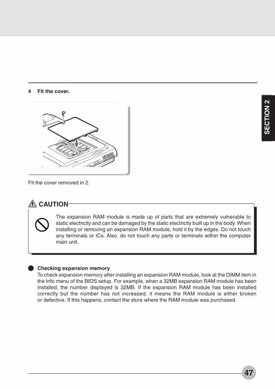
4 Fit the cover.
Fit the cover removed in 2.
CAUTION
The expansion RAM module is made up of parts that are extremely vulnerable tostatic electricity and can be damaged by the static electricity built up in the body. Wheninstalling or removing an expansion RAM module, hold it by the edges. Do not touchany terminals or ICs. Also, do not touch any parts or terminals within the computermain unit.
Checking expansion memoryTo check expansion memory after installing an expansion RAM module, look at the DIMM item inthe Info menu of the BIOS setup. For example, when a 32MB expansion RAM module has beeninstalled, the number displayed is 32MB. If the expansion RAM module has been installedcorrectly but the number has not increased, it means the RAM module is either brokenor defective. If this happens, contact the store where the RAM module was purchased.
Bis Sec 2 (39-49) 01/11/1999, 15:1147

48
Removing an Expansion RAM Module
This item explains how to remove an expansion RAM module.
WARNING
Always turn off the computerand disconnect the ACadaptor when removing anexpansion RAM module inorder to avoid electric shock.
1 Turn off the computer and disconnectthe AC adaptor from it.
2 Remove the cover.
Remove the cover on the bottom of thecomputer main unit.
3 Remove the expansion RAM module.
Open the hooks on both sides that retain theexpansion RAM module to the left and right,then remove the expansion RAM module fromthe slot.
Bis Sec 2 (39-49) 01/11/1999, 15:1148
SE
CT
ION
2
49
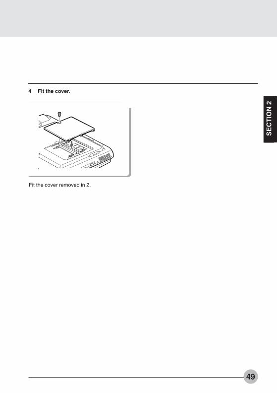
4 Fit the cover.
Fit the cover removed in 2.
Bis Sec 2 (39-49) 01/11/1999, 15:1149

50
SECTION 2
4. Mouse
Connecting the Mouse
1 Turn off the computer and disconnectthe AC adaptor from it.
2 Connect the connector at the end ofthe mouse cable to the expansionkeyboard/mouse connector on the rearside of the computer main unit.
Have the arrow marked on the connectorfacing down.
Using the Mouse
Moving the mousePlace your hand on the mouse so that your fingers are resting on the left and right buttons andmove the mouse by sliding it over your desktop or other smooth surface. The arrow (called themouse pointer) on the screen moves in the same way as the mouse. Try moving the mouse whilewatching the screen.
Bis Sec 2 (50-60) 01/11/1999, 15:1150

51
SE
CT
ION
2
Button operations
• Click
• Double click
• Pointing
• Dragging
Click
Press the left mouse button once until it clicks. The action ofpressing the right button once firmly enough that it clicks is calleda “right click”.
Press the mouse left button two times quickly in a row.
Align the mouse pointer with a menu item. When there isanother level for the menu item the cursor is on (when - isdisplayed at the right of the menu item), that menu level isdisplayed.
Move the mouse pointer with the mouse left button held down,then release the button at the desired position.
Click, click
Press
Release
Bis Sec 2 (50-60) 01/11/1999, 15:1151

52
SECTION 2
5. Numeric Keypad
Connecting a Numeric Keypad
This item explains how to connect a numeric keypad.
1 Turn off the computer and disconnectthe AC adaptor from it.
2 Connect the numeric keypad.
Have the arrow marked on the connectorfacing down.
Critical PointWhen a mouse is connected to the numerickeypad mouse connector, the mouseconnector on the computer main unitcannot be used.
You can adjust the tilt of the numeric keypadwith the tilt feet on the bottom of thenumeric keypad.
Mouse connector
Bis Sec 2 (50-60) 01/11/1999, 15:1152

53
SE
CT
ION
2
SECTION 2
6. Floppy Disk Unit
Installing a Floppy Disk Unit
This item explains how to install a floppy disk unit.
WARNING
Always turn off the computerand disconnect the ACadaptor when installing afloppy disk unit in order toavoid electric shock.
1 Turn off the computer and disconnectthe AC adaptor from it.
2 Install the floppy disk unit.
Bis Sec 2 (50-60) 01/11/1999, 15:1153

54
Precautions for Floppy Disk Unit
Take the following precautions when using the floppy disk unit in order to prevent damaging it.
Avoid storing the floppy disk unit in extremely hot and cold locations, or in locations subject tosevere temperature changes.
Keep the floppy disk unit out of direct sunlight and away from heating equipment.
Avoid storing the floppy disk unit in locations subject to shock or vibration.
Avoid using the floppy disk unit in damp or dusty locations.
Never use the floppy disk unit with any liquid, metal or other foreign matter inside it. If anyforeign matter gets inside the floppy disk unit, consult the store from where it was purchasedor the nearest Fujitsu Personal Echo Center.
Wipe the floppy disk unit clean with a dry soft cloth or with a soft cloth moistened with water ora neutral detergent solution. Never use benzine, paint thinner or other volatile material.
Never disassemble or dismantle this product.
Critical PointUse the floppy disk unit away from equipment that creates a magnetic field such as a CRTmonitor or an AC adaptor.
Bis Sec 2 (50-60) 01/11/1999, 15:1154

55
SE
CT
ION
2
Removing a Floppy Disk Unit
This item explains how to remove a floppy disk unit.
WARNING
Always turn off thecomputer and disconnectthe AC adaptor whenremoving a floppy disk unitin order to avoid electricshock.
Critical PointWhen you remove a connector,press both sides of the connectorand pull it. Pulling a cableunnecessarily can cause damage.
1 Turn off the computer and disconnectthe AC adaptor from it.
2 Remove the floppy disk unit.
Bis Sec 2 (50-60) 01/11/1999, 15:1155

56
Insert the floppy disk with the label upwardsand the shutter side first until the EJECTbutton springs out.
Loading/Ejecting a Floppy Disk
LoadingInsert into the floppy disk drive.
Ejecting
Label
Check that the floppy disk unit’s access lampis out, then press the EJECT button.
EJECT button
Access lamp
Critical PointIf you eject the floppy disk while the floppydisk unit’s access indicator is still on, thereis a risk of losing the data on the disk.
When you do not want to erase the datasaved on the disk, or when you do not wantto write additional data, slide the floppydisk’s write protector so that the hole isopen (WRITE PROTECT state). When youwant to write data again, slide the writeprotector so that the hole is closed.
This item explains how to load and eject floppy disks.
Write protector
WRITEENABLE
WRITEPROTECT
Bis Sec 2 (50-60) 01/11/1999, 15:1156

57
SE
CT
ION
2
SECTION 2
7. Printer
Connecting a Printer
This item explains how to connect a printer to the parallel interface connector on the rear ofthe computer main unit.
WARNING
Always turn off the computer main unit and disconnect the AC adaptor beforeconnecting/disconnecting a printer. Connecting/disconnecting a printer with the poweron can cause electric shock.
CAUTION
When connecting cables, read this manual carefully and make sure to connectcorrectly. Using this computer with cables incorrectly connected can causebreakdown of the computer main unit and the printer.
Critical PointConnecting a printer requires a printer cable. Sometimes this cable does not come with theprinter. Even if the printer cable does come with the printer, sometimes it has the wrongconfiguration for this computer. In either of these cases, separately purchase a printer cablethat you can connect to this computer.
How to connect the printer depends on the printer. For details, refer to the printer manual.
Bis Sec 2 (50-60) 01/11/1999, 15:1157
58
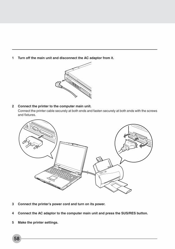
1 Turn off the main unit and disconnect the AC adaptor from it.
2 Connect the printer to the computer main unit.Connect the printer cable securely at both ends and fasten securely at both ends with the screwsand fixtures.
�
3 Connect the printer’s power cord and turn on its power.
4 Connect the AC adaptor to the computer main unit and press the SUS/RES button.
5 Make the printer settings.
Bis Sec 2 (50-60) 01/11/1999, 15:1158

59
SE
CT
ION
2
SECTION 2
8. CRT Monitor
Connecting an External CRT Monitor
An external CRT monitor can be connected to this computer. This item explains how toconnect a CRT monitor to the CRT interface connector on the rear of the computer main unit.
WARNING
Always turn off the computer main unit and disconnect the AC adaptor beforeconnecting/disconnecting a CRT monitor. Connecting/disconnecting a CRT monitorwith the power on can cause electric shock.
CAUTION
When connecting cables, read this manual carefully and make sure to connectcorrectly. Using this computer with cables incorrectly connected can causebreakdown of the computer main unit and the CRT monitor.
1 Turn off the main unit and disconnect the AC adaptor from it.
Bis Sec 2 (50-60) 01/11/1999, 15:1159
60
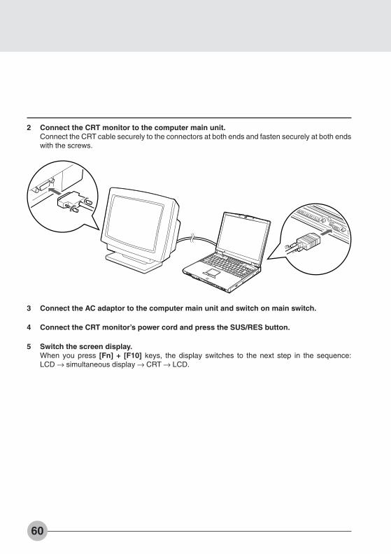
2 Connect the CRT monitor to the computer main unit.Connect the CRT cable securely to the connectors at both ends and fasten securely at both endswith the screws.
3 Connect the AC adaptor to the computer main unit and switch on main switch.
4 Connect the CRT monitor’s power cord and press the SUS/RES button.
5 Switch the screen display.When you press [Fn] + [F10] keys, the display switches to the next step in the sequence:LCD → simultaneous display → CRT → LCD.
Bis Sec 2 (50-60) 01/11/1999, 15:1160
61
SE
CT
ION
2
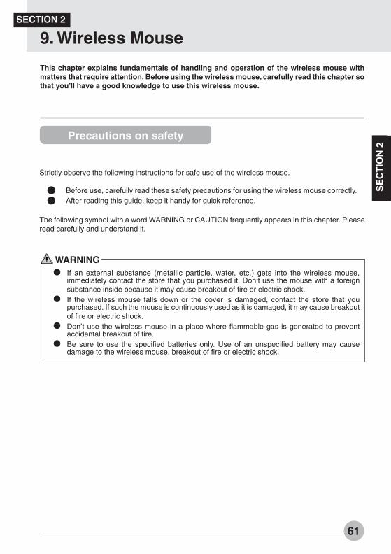
This chapter explains fundamentals of handling and operation of the wireless mouse withmatters that require attention. Before using the wireless mouse, carefully read this chapter sothat you’ll have a good knowledge to use this wireless mouse.
SECTION 2
9. Wireless Mouse
Precautions on safety
Strictly observe the following instructions for safe use of the wireless mouse.
Before use, carefully read these safety precautions for using the wireless mouse correctly.After reading this guide, keep it handy for quick reference.
The following symbol with a word WARNING or CAUTION frequently appears in this chapter. Pleaseread carefully and understand it.
WARNINGIf an external substance (metallic particle, water, etc.) gets into the wireless mouse,immediately contact the store that you purchased it. Don’t use the mouse with a foreignsubstance inside because it may cause breakout of fire or electric shock.If the wireless mouse falls down or the cover is damaged, contact the store that youpurchased. If such the mouse is continuously used as it is damaged, it may cause breakoutof fire or electric shock.Don’t use the wireless mouse in a place where flammable gas is generated to preventaccidental breakout of fire.Be sure to use the specified batteries only. Use of an unspecified battery may causedamage to the wireless mouse, breakout of fire or electric shock.
Bis Sec 2 (61-68) 01/11/1999, 15:1161

62
CAUTION
Don’t leave the wireless mouse in a place where it is directly exposed to the sun or thetemperature is expected to rise extremely, for example, in a car exposed to the scorchingsun, for a long time. Extremely high temperature may cause the cover and other parts ofthe wireless mouse to be heated, deformed, melted, or to fire because its inside is heated.Avoid using the wireless mouse in a dusty or humid place. If the wireless mouse gets dustor moisture inside, it may cause failure of the mouse or outbreak of fire.Don’t put the wireless mouse in a place where it is exposed to steam or soot such as in akitchen or near a humidifier, because it may cause a fire.Neither dismantle the wireless mouse nor remove any part from it. If it is done so, it maycause fire or electric shock.Don’t cover or wrap the wireless mouse with cloth or other thing. If done so, the mousebecomes hot because of poor radiation of heat and it may cause deformation of the coverand breakout of fire. Use the wireless mouse in a well-ventilated condition.Don’t insert or drop a metallic particle, flammable thing or foreign substance into the wire-less mouse. If there is a foreign substance inside the wireless mouse, it may cause a fire.Don’t put the wireless mouse on a slant or unstable plane or in a place where it is easilyaffected by strong vibration. If the mouse falls down, it may cause damage to the mouse orinjury to a person.Don’t give a strong shock or vibration to the wireless mouse, otherwise the mouse may fallinto failure.Don’t clean the wireless mouse with thinner or benzene, or don’t spray insecticide or thelike to it. Such the chemical may cause the mouse to crack or catch fire.
Bis Sec 2 (61-68) 01/11/1999, 15:1162

63
SE
CT
ION
2
Preparation and Preliminary knowledge
Loading of batteriesLoad the wireless mouse with two AAA-size alkaline batteries referring to the article “Replacingbatteries” of this manual.
H-L-OFF switchInfrared transmission power of this wirelessmouse can be switched between low and highwith the H-L-OFF switch. Set this switch to theH (High power mode) or L (Low power mode)position taking the operating environment andconditions into consideration. When this mouseis out of use, set this switch to the OFF positionfor saving battery power.
Operating methodThis wireless mouse transmits data on mouse operation to the personal computer on infraredrays. When operating the wireless mouse, point its transmitter part at the photosensor of thepersonal computer. The operating method of this wireless mouse is the same as the general PS/2 mouse.It is recommended to use this wireless mouse within a distance of 1.5 m (High power mode) or0.5 m (Low power mode) from the personal computer.
Critical PointsThe one-touch operation buttons cannot beused in the following cases.The illustration of a personal computerappearing on this page is just a reference.The outward appearance slightly differs withthe model. Before using this wireless mouse,check the personal computer for the locationof the photosensor for the wireless mouse.
OFFLH
Wireless mouse
Photosensorfor wirelessmouse
Bis Sec 2 (61-68) 01/11/1999, 15:1163
64
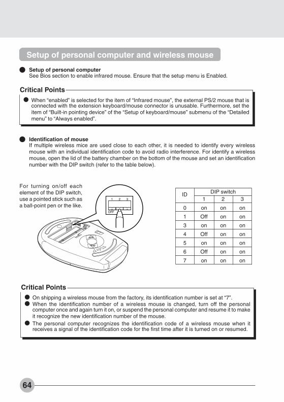
Critical PointsWhen “enabled” is selected for the item of “Infrared mouse”, the external PS/2 mouse that isconnected with the extension keyboard/mouse connector is unusable. Furthermore, set theitem of “Built-in pointing device” of the “Setup of keyboard/mouse” submenu of the “Detailedmenu” to “Always enabled”.
Setup of personal computer and wireless mouse
Setup of personal computerSee Bios section to enable infrared mouse. Ensure that the setup menu is Enabled.
Identification of mouseIf multiple wireless mice are used close to each other, it is needed to identify every wirelessmouse with an individual identification code to avoid radio interference. For identify a wirelessmouse, open the lid of the battery chamber on the bottom of the mouse and set an identificationnumber with the DIP switch (refer to the table below).
1 2 3
OFF
For turning on/off eachelement of the DIP switch,use a pointed stick such asa ball-point pen or the like.
DIP switch1 2 3
0 on on on
1 Off on on
3 on on on
4 Off on on
5 on on on
6 Off on on
7 on on on
ID
Critical PointsOn shipping a wireless mouse from the factory, its identification number is set at “7”.When the identification number of a wireless mouse is changed, turn off the personalcomputer once and again turn it on, or suspend the personal computer and resume it to makeit recognize the new identification number of the mouse.The personal computer recognizes the identification code of a wireless mouse when itreceives a signal of the identification code for the first time after it is turned on or resumed.
Bis Sec 2 (61-68) 01/11/1999, 15:1164

65
SE
CT
ION
2
Replacing batteries
1 Remove the lid of the battery chamber. 2 Remove the old batteries.
3 Set new batteries in the battery chamber.Pay heed to the polarities (+ and - poles) ofeach battery so as to set it in correctorientation.
4 Fit the lid of the battery chamber tothe wireless mouse.
CAUTIONCheck the orientation (directions of + and - poles) of each battery so that it is correctly setin the battery chamber.Don’t use a used battery mixedly with a new battery or two new batteries that are differentin brand or rating from each other.When the wireless mouse won’t be used for a long time, remove the batteries to prevent itfrom trouble such as leak of electrolyte. If electrolyte leaks from the battery, clean the insideof the battery chamber, particularly metal terminals, and its periphery with soft cloth that ismoistened with water once and then tightly squeezed to remove electrolyte, and carefullywipe out moisture with dry soft cloth.When you get electrolyte on your body, carefully wash it out with water. If electrolyte getsinto your eyes or mouth, immediately wash it out with water and consult a doctor as soon aspossible.Be careful not to make a short-circuit between terminals of the battery chamber.Don’t put any battery in water or fire. Don’t take any battery apart to pieces.Don’t charge the battery of this wireless mouse.Don’t directly solder the battery.Don’t keep batteries in an extreme temperature condition.Don’t give a strong shock to batteries.When disposing used batteries, follow the regulations and directions of the local autonomyconcerned.
Bis Sec 2 (61-68) 01/11/1999, 15:1165
66
For good maintenance
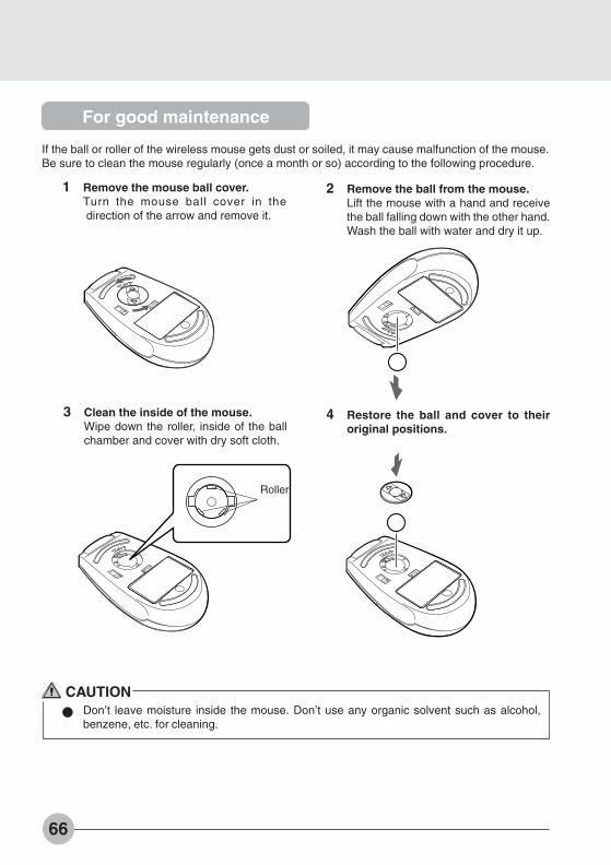
If the ball or roller of the wireless mouse gets dust or soiled, it may cause malfunction of the mouse.Be sure to clean the mouse regularly (once a month or so) according to the following procedure.
1 Remove the mouse ball cover.Turn the mouse ball cover in the direction of the arrow and remove it.
2 Remove the ball from the mouse.Lift the mouse with a hand and receivethe ball falling down with the other hand.Wash the ball with water and dry it up.
3 Clean the inside of the mouse.Wipe down the roller, inside of the ballchamber and cover with dry soft cloth.
4 Restore the ball and cover to theiroriginal positions.
CAUTIONDon’t leave moisture inside the mouse. Don’t use any organic solvent such as alcohol,benzene, etc. for cleaning.
Roller
Bis Sec 2 (61-68) 01/11/1999, 15:1166
67
SE
CT
ION
2
Caution
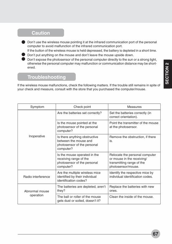
Don’t use the wireless mouse pointing it at the infrared communication port of the personalcomputer to avoid malfunction of the infrared communication port.If the button of the wireless mouse is held depressed, the battery is depleted in a short time.Don’t put anything on the mouse and don’t leave the mouse upside down.Don’t expose the photosensor of the personal computer directly to the sun or a strong light,otherwise the personal computer may malfunction or communication distance may be short-ened.
Troubleshooting
If the wireless mouse malfunctions, check the following matters. If the trouble still remains in spite ofyour check and measure, consult with the store that you purchased the computer/mouse.
Check point
Are the batteries set correctly?
Is the mouse pointed at thephotosensor of the personalcomputer?
Is there anything obstructivebetween the mouse andphotosensor of the personalcomputer?
Is the mouse operated in thereceiving range of thephotosensor of the personalcomputer?
Are the multiple wireless miceidentified by their individualidentification codes?
The batteries are depleted, aren’tthey?
The ball or roller of the mousegets dust or soiled, doesn’t it?
Measures
Set the batteries correctly (incorrect orientation).
Point the transmitter of the mouseat the photosensor.
Remove the obstruction, if thereis.
Relocate the personal computeror mouse in the receiving/transmitting range of thephotosensor/mouse.
Identify the respective mice byindividual identification codes.
Replace the batteries with newones.
Clean the inside of the mouse.
Symptom
Radio interference
Abnormal mouseoperation
Inoperative
Bis Sec 2 (61-68) 01/11/1999, 15:1167

68
Specifications
Description
Infrared transmission
6 months approximately (under operating conditions:8-hours/day, 5-days/week, net operating rate of mouse
= 10 %)(condition not in use: power off,
temperature 20 degree centigrade)
H: Distance - within 1.5 m, angle - rightand left 0 degree,
Up and down 0 degreeL: Distance - within 0.5 m, angle - right and left +45
degrees and - 45 degrees ,up 45 degrees , down 15 degrees
Item
Transmission system
Service life of battery(alkaline battery)
(in Low Power mode)
Operable range
CAUTIONThis wireless mouse falls under the class B information processor conforming to the VCCI(Voluntary Control Conference Against Jamming Caused by Information Processor)standard.This wireless mouse is designed to be used in the standard home environment, however, ifit is used near a radio or TV set, it may cause radio interference.Use this wireless mouse correctly following the instructions of this user’s guide.
Bis Sec 2 (61-68) 01/11/1999, 15:1168

SE
CT
ION
3
33333
SECTIONSECTIONSECTIONSECTIONSECTIONSECTIONSECTIONSECTIONSECTIONSECTION
33333
Bis Sec 3 (69-78) 01/11/1999, 15:1169

70
SECTION 3
1. BIOS setup
Snapshots of the BIOS setup screen and the possible setup options is shown in the following sections.Underlined setup options show the default settings.Columns between Selections and Note show the security level of each setup item. ‘S’ meansthat the item needs the supervisor password security level and can not be changed with theuser password security level.
1.1 Main Menu
Setup Item
System Time
System Date
Floppy Diskette A
Primary Master
Secondary Master
Language
Selections
00:00:00 to 23:59:59
01/01/1981 to12/31/2099
Disabled1.44/1.25 MB 3 1/2”
English (US)xxxxxx (JP)
S
Note (Item Specific Help)
Adjust calendar clock.<Tab>, <Shift-Tab>, or <Enter> selects field.
Adjust calendar clock.<Tab>, <Shift-Tab>, or <Enter> selects field.
Select floppy drive type. 1.44/1.25 MB 3 1/2 ”is the valid value.Selects floppy type. Note that 1.25 MB, 3 1/2”references a 1024 byte/sector Japanese mediaformat.
Configure primary master ATA/ATAPI device.Configures ATA/ATAPI device.
Configure secondary master ATA/ATAPIdevice.Configures ATA/ATAPI device.
The default setting differs between US/European model and Japanese model. Selectthe display language for the BIOS.
Figure 1-1 Main menu
F1 Help ↑↓ Select Item -/Space Change Value F9 Setup DefaultsESCExit ←→ Select Menu Enter Select :Sub-MenuF10Save and Exit
PhoenixBIOS Setup UtilityMain Advanced Security Power Boot Info Exit
System Time: [12:34:56]System Date: [06/02/1999]
Floppy Diskette A: [1.44/1.2 MB 3.5”]
:Primary Master: [FUJITSU MHA2102AT]:Secondary Master: [MATSHITADVD-ROM SR-8174-(PM)]
Language: [English (US)]
Item Specific Help
Adjust calendar clock
<Tab>, <Shift-Tab>, or<Enter> selects field.
Table 1-1 Main menu options
Table 1-1 Main menu options
Bis Sec 3 (69-78) 01/11/1999, 15:1170

71
SE
CT
ION
3
Figure 1-2 Main - Primary/Secondary Master Menu
Setup ItemType
Cylinders
Heads
SelectionsAutoNoneCD-ROMATAPI RemovableUser
0 to 65535
1 to 16
Note (Item Specific Help)Select ATA/ATAPI device type. If ‘Auto’ isselected, the type is automatically identifiedat POST by the BIOS. It does not carry outCylinder/Head/Sector display in the case ofover 8.4GB-HDD when Auto mode. If ‘None’is selected, all of the following setup items donot appear. When ‘User’ is selected, you canspecify Cylinders, Heads and Sectors.User = you enter parameters of hard-diskdrive installed at this connection.Auto = autotypes ATA/ATAPI drive installedhere.CD-ROM = a CD-ROM drive is installed here.ATAPI Removable = removable disk drive isinstalled here.
This item appears when ‘Auto’ is selected andthe type is identified as hard disk, or ‘User’ isselected. When ‘User’ is selected, you canchange the value.Specify the number of Cylinders.
This item appears when ‘Auto’ is selected andthe type is identified as hard disk, or ‘User’ isselected. When ‘User’ is selected, you canchange the value.Specify the number of Heads.
1.1.1 Main - Primary Master, Secondary Master Menu
S
S
F1 Help ↑↓ Select Item -/Space Change Value F9 Setup DefaultsESCExit ←→ Select Menu Enter Select :Sub-MenuF10Save and Exit
PhoenixBIOS Setup UtilityMain Advanced Security Power Boot Info Exit
Primary Master [FUJITSU MHG2102AT]
Type: [AUTO]Maximum Capacity: 10056 MB
Multi-Sector Transfers: [16 Sectors]LBA Mode Control: [Enabled]PIO Transfer Mode: [Fast PIO 4]DMA Transfer Mode: [Ultra DMA 2]
Item Specific Help
Select ATA/ATAPIdrive installed here.
[Auto]The BIOS auto-typethe drive on boottime.
Except [Auto]You enter parametersof the drive.
[None]The drive is disabled.
Bis Sec 3 (69-78) 01/11/1999, 15:1171
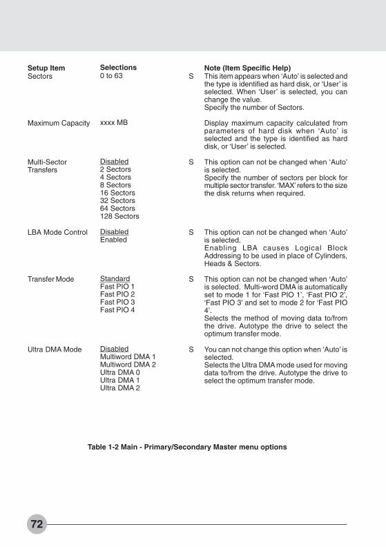
72
Setup ItemSectors
Maximum Capacity
Multi-SectorTransfers
LBA Mode Control
Transfer Mode
Ultra DMA Mode
Selections0 to 63
xxxx MB
Disabled2 Sectors4 Sectors8 Sectors16 Sectors32 Sectors64 Sectors128 Sectors
DisabledEnabled
StandardFast PIO 1Fast PIO 2Fast PIO 3Fast PIO 4
DisabledMultiword DMA 1Multiword DMA 2Ultra DMA 0Ultra DMA 1Ultra DMA 2
Note (Item Specific Help)This item appears when ‘Auto’ is selected andthe type is identified as hard disk, or ‘User’ isselected. When ‘User’ is selected, you canchange the value.Specify the number of Sectors.
Display maximum capacity calculated fromparameters of hard disk when ‘Auto’ isselected and the type is identified as harddisk, or ‘User’ is selected.
This option can not be changed when ‘Auto’is selected.Specify the number of sectors per block formultiple sector transfer. ‘MAX’ refers to the sizethe disk returns when required.
This option can not be changed when ‘Auto’is selected.Enabling LBA causes Logical BlockAddressing to be used in place of Cylinders,Heads & Sectors.
This option can not be changed when ‘Auto’is selected. Multi-word DMA is automaticallyset to mode 1 for ‘Fast PIO 1’, ‘Fast PIO 2’,‘Fast PIO 3’ and set to mode 2 for ‘Fast PIO4’.Selects the method of moving data to/fromthe drive. Autotype the drive to select theoptimum transfer mode.
You can not change this option when ‘Auto’ isselected.Selects the Ultra DMA mode used for movingdata to/from the drive. Autotype the drive toselect the optimum transfer mode.
S
S
S
S
S
Table 1-2 Main - Primary/Secondary Master menu options
Bis Sec 3 (69-78) 01/11/1999, 15:1172
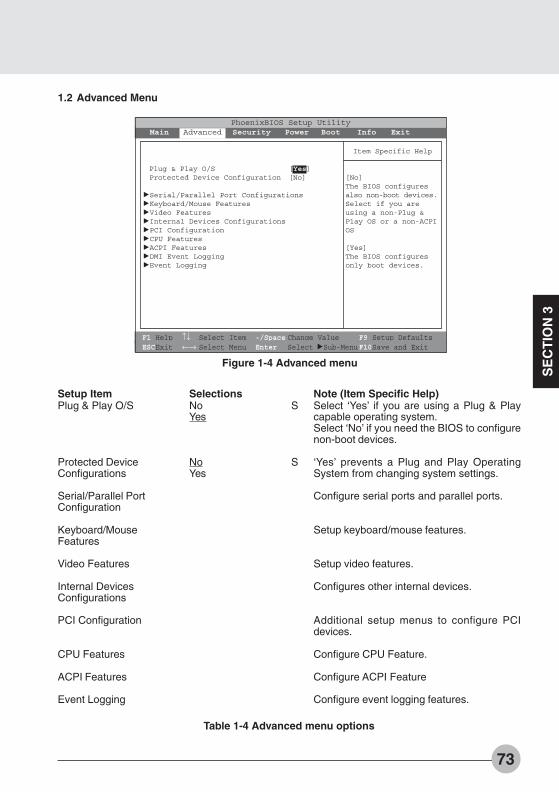
73
SE
CT
ION
3
Figure 1-4 Advanced menu
1.2 Advanced Menu
Setup ItemPlug & Play O/S
Protected DeviceConfigurations
Serial/Parallel PortConfiguration
Keyboard/MouseFeatures
Video Features
Internal DevicesConfigurations
PCI Configuration
CPU Features
ACPI Features
Event Logging
SelectionsNoYes
NoYes
Note (Item Specific Help)Select ‘Yes’ if you are using a Plug & Playcapable operating system.Select ‘No’ if you need the BIOS to configurenon-boot devices.
‘Yes’ prevents a Plug and Play OperatingSystem from changing system settings.
Configure serial ports and parallel ports.
Setup keyboard/mouse features.
Setup video features.
Configures other internal devices.
Additional setup menus to configure PCIdevices.
Configure CPU Feature.
Configure ACPI Feature
Configure event logging features.
S
S
Table 1-4 Advanced menu options
F1 Help ↑↓ Select Item -/Space Change Value F9 Setup DefaultsESCExit ←→ Select Menu Enter Select :Sub-MenuF10Save and Exit
PhoenixBIOS Setup UtilityMain Advanced Security Power Boot Info Exit
Plug & Play O/S [Yes]Protected Device Configuration [No]
:Serial/Parallel Port Configurations:Keyboard/Mouse Features:Video Features:Internal Devices Configurations:PCI Configuration:CPU Features:ACPI Features:DMI Event Logging:Event Logging
Item Specific Help
[No]The BIOS configuresalso non-boot devices.Select if you areusing a non-Plug &Play OS or a non-ACPIOS
[Yes]The BIOS configuresonly boot devices.
Bis Sec 3 (69-78) 01/11/1999, 15:1173

74
Figure 1-5 Advanced - I/O Device Configuration menu
1.2.1 Advanced - Serial/Parallel Port Configuration Menu
Setup ItemSerial port
Base I/O address
Interrupt
Infrared Port
Mode
Base I/O address
SelectionsDisabledEnabledAuto
3F8-3FF2F8-2FF3E8-3EF2E8-2EF
IRQ 3IRQ 4IRQ 10IRQ 11
DisabledEnabledAuto
IrDAFIR
3F8-3FF2F8-2FF3E8-3EF2E8-2EF
S
S
S
S
S
S
Note (Item Specific Help)[Disabled] The port is disabled.[Enabled] The port enabled with userconfiguration.[Auto] The port is configured depending on‘Plug and Play OS’ setting.
Select the I/O address for the port.
Select the interrupt number for the port.
[Disabled] The port is disabled.[Enabled] The port enabled with userregistration.[Auto] The port is configured depending on‘Plug and Play OS’ setting.
Select the mode for the Infrared port.
Set the I/O address for the port.
F1 Help ↑↓ Select Item -/Space Change Value F9 Setup DefaultsESCExit ←→ Select Menu Enter Select :Sub-MenuF10Save and Exit
PhoenixBIOS Setup UtilityMain Advanced Security Power Boot Info Exit
Serial/Parallel Port Configuration
Serial port : [Enable]I/O Address: [3F8-3FF]Interrupt: [IRQ 4]
Infrared Port : [Enabled]Mode: [FIR]I/O address: [2E8-2EF]Interrupt: [IRQ 3]I/O address: [118-11F]DMA channel: [DMA 3]
Parallel port: [Enabled]Mode: [Bi-directional]I/O address: [378-37F]Interrupt: [IRQ 7]
Item Specific Help
[Disabled]The port is disabled
[Enabled]The port is enabledwith userconfiguration
[Auto]A Plug & Play OS oran ACPI OS willconfigure the port.
Bis Sec 3 (69-78) 01/11/1999, 15:1174

75
SE
CT
ION
3
Setup ItemInterrupt
Base I/O address
DMA channel
Parallel port
Mode
Base I/O address
Interrupt
SelectionsIRQ 3IRQ 4IRQ 10IRQ 11
100-107108-10F110-117118-11F
DMA 1DMA 3
DisabledEnabledAuto
Output onlyBi-directionalECP
378-37F278-27F3BC-3BF
IRQ 5IRQ 7
S
S
S
S
S
S
S
Note (Item Specific Help)Select the interrupt number for the port.
Select the I/O address for the FIR.
Select the DMA channel for the FIR.
[Disabled] The port is disabled.[Enabled] The port is enabled with userconfiguration.[Auto] the port is configured depending on‘Plug and Play OS’ setting
Select the mode for the parallel port.
Select the I/O address for the port.
Select the Interrupt number for the port.
Table 1-5 Advanced - I/O Device Configuration menu options
Bis Sec 3 (69-78) 01/11/1999, 15:1175

76
Figure 1-6 Advanced - Keyboard/Mouse Features menu
1.2.2 Advanced - Keyboard/Mouse Features Menu
Setup ItemNumlock
Hot Plug
Infrared Mouse
Internal PointingDevice
SelectionsAutoOnOff
DisabledEnabled
DisabledEnabled
Auto DisabledAlways Enabled
S
S
S
S
Note (Item Specific Help)Selects Power-on state for Numlock.
Keyboard/Mouse Hot Plug functions.
If Infrared Mouse is enabled, PS/2 externalpointing device will be disabled. To use internalpointing device simultaneously, please select“Always Enabled” in Internal Pointing Devicemenu.
If Always Enabled is selected, the internalpointing device is always enabled. If AutoDisabled is selected, the internal pointingdevice is disabled when an external pointingdevice is connected with the PS/2 port.However, if no pointing device is connected,the internal pointing device is enabled.
Table 1-6 Advanced - Keyboard/Mouse Features menu options
F1 Help ↑↓ Select Item -/Space Change Value F9 Setup DefaultsESCExit ←→ Select Menu Enter Select :Sub-MenuF10Save and Exit
PhoenixBIOS Setup UtilityMain Advanced Security Power Boot Info Exit
Keyboard/Mouse Features
Numlock: [Auto]Hot plug: [Enabled]Internal Pointing Device: [Auto Disabled]Infrared Mouse: [Disabled]
Item Specific Help
Selects power-onstate for Numlock.
Bis Sec 3 (69-78) 01/11/1999, 15:1176
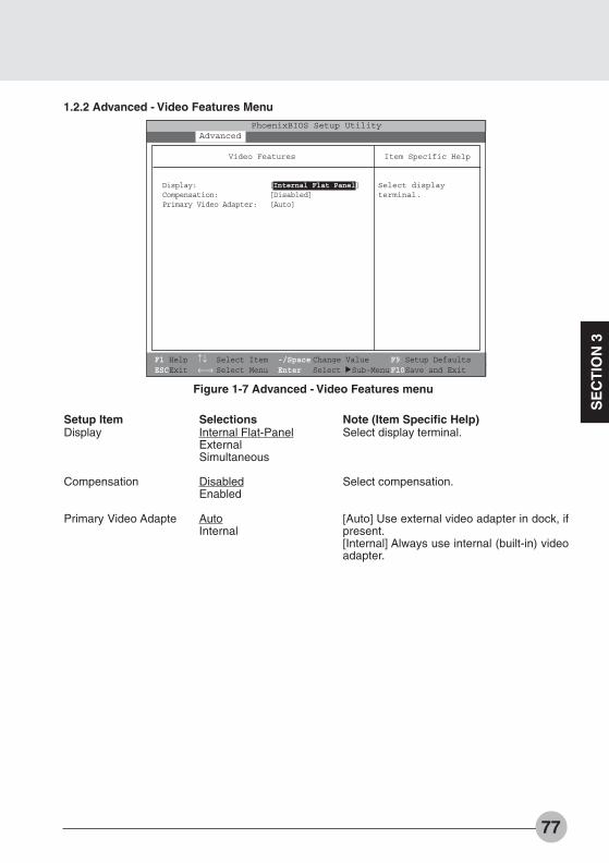
77
SE
CT
ION
3
Figure 1-7 Advanced - Video Features menu
1.2.2 Advanced - Video Features Menu
Setup ItemDisplay
Compensation
Primary Video Adapte
SelectionsInternal Flat-PanelExternalSimultaneous
DisabledEnabled
AutoInternal
Note (Item Specific Help)Select display terminal.
Select compensation.
[Auto] Use external video adapter in dock, ifpresent.[Internal] Always use internal (built-in) videoadapter.
F1 Help ↑↓ Select Item -/Space Change Value F9 Setup DefaultsESCExit ←→ Select Menu Enter Select :Sub-MenuF10Save and Exit
PhoenixBIOS Setup UtilityMain Advanced Security Power Boot Info Exit
Video Features
Display: [Internal Flat Panel]Compensation: [Disabled]Primary Video Adapter: [Auto]
Item Specific Help
Select displayterminal.
Bis Sec 3 (69-78) 01/11/1999, 15:1177
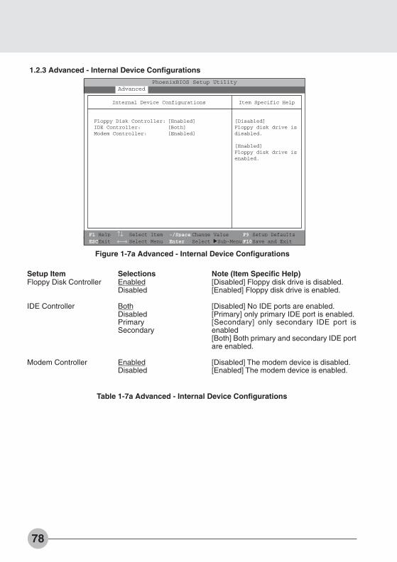
78
Figure 1-7a Advanced - Internal Device Configurations
1.2.3 Advanced - Internal Device Configurations
Setup ItemFloppy Disk Controller
IDE Controller
Modem Controller
SelectionsEnabledDisabled
BothDisabledPrimarySecondary
EnabledDisabled
Note (Item Specific Help)[Disabled] Floppy disk drive is disabled.[Enabled] Floppy disk drive is enabled.
[Disabled] No IDE ports are enabled.[Primary] only primary IDE port is enabled.[Secondary] only secondary IDE port isenabled[Both] Both primary and secondary IDE portare enabled.
[Disabled] The modem device is disabled.[Enabled] The modem device is enabled.
F1 Help ↑↓ Select Item -/Space Change Value F9 Setup DefaultsESCExit ←→ Select Menu Enter Select :Sub-MenuF10Save and Exit
PhoenixBIOS Setup UtilityMain Advanced Security Power Boot Info Exit
Internal Device Configurations
Floppy Disk Controller: [Enabled]IDE Controller: [Both]Modem Controller: [Enabled]
Item Specific Help
[Disabled]Floppy disk drive isdisabled.
[Enabled]Floppy disk drive isenabled.
Table 1-7a Advanced - Internal Device Configurations
Bis Sec 3 (69-78) 01/11/1999, 15:1178

79
SE
CT
ION
3
Figure 1-8 Advanced - PCI Configuration menu
1.2.4 Advanced - PCI Configuration Menu
Setup ItemIRQ Reservation
Selections Note (Item Specific Help)Reserve specific IRQs for use by legacy ISAdevices.
Table 1-8 Advanced - PCI Configuration menu options
F1 Help ↑↓ Select Item -/Space Change Value F9 Setup DefaultsESCExit ←→ Select Menu Enter Select :Sub-MenuF10Save and Exit
PhoenixBIOS Setup UtilityMain Advanced Security Power Boot Info Exit
PCI Configuration
:IRQ Reservation
Item Specific Help
Reserve specificIRQs for use bylegacy ISA devices.
Bis Sec 3 (80-87) 01/11/1999, 15:1179

80
Figure 1-9 Advanced - PCI Configuration - IRQ Reservation menu
Setup ItemIRQ 3
IRQ 4
IRQ 5
IRQ 7
IRQ 9
IRQ 10
IRQ 11
SelectionsAvailableReserved
AvailableReserved
AvailableReserved
AvailableReserved
AvailableReserved
AvailableReserved
AvailableReserved
Note (Item Specific Help)If [Reserved] is selected, the BIOS reservesIRQ 3 for use by legacy ISA devices and doesnot use it for embedded PCI or ISA devices.IRQ 3 is removed from the IRQ bitmap in thePCI IRQ routing table.Reserve the specified IRQ for use by legacyISA devices.
Reserves IRQ 4.Reserve the specified IRQ for use by legacyISA devices.
Reserves IRQ 5.Reserve the specified IRQ for use by legacyISA devices.
Reserves IRQ 7.Reserve the specified IRQ for use by legacyISA devices.
Reserves IRQ 9.Reserve the specified IRQ for use by legacyISA devices.
Reserves IRQ 10.Reserve the specified IRQ for use by legacyISA devices.
Reserves IRQ 11.Reserve the specified IRQ for use by legacyISA devices.
1.2.4.1 Advanced - PCI Configuration - IRQ Reservation Menu
S
S
S
S
S
S
S
Table 1-9 Advanced - PCI Configuration - IRQ Reservation menu options
F1 Help ↑↓ Select Item -/Space Change Value F9 Setup DefaultsESCExit ←→ Select Menu Enter Select :Sub-MenuF10Save and Exit
PhoenixBIOS Setup UtilityMain Advanced Security Power Boot Info Exit
IRQ Reservation
IRQ 3: [Available]IRQ 4: [Available]IRQ 5: [Available]IRQ 7: [Available]IRQ 9: [Available]IRQ 10: [Available]IRQ 11: [Available]
Item Specific Help
Reserve thespecified IRQ foruse by legacy ISAdevices.
Bis Sec 3 (80-87) 01/11/1999, 15:1180

81
SE
CT
ION
3
Figure 1-9a Advanced - CPU Features
1.2.4.2 Advanced - CPU Features
F1 Help ↑↓ Select Item -/Space Change Value F9 Setup DefaultsESCExit ←→ Select Menu Enter Select :Sub-MenuF10Save and Exit
PhoenixBIOS Setup UtilityMain Advanced Security Power Boot Info Exit
CPU Features
Processor Serial Number: [Disabled]
Item Specific Help
Configures ProcessorSerial Numberfeature of PentiumIII processor
[Disabled]Processor SerialNumber feature isdisabled
[Enabled]Processor SerialNumber feature isenabled
Figure 1-9a Advanced - CPU Features
1.2.4.3 Advanced - CPU Features
F1 Help ↑↓ Select Item -/Space Change Value F9 Setup DefaultsESCExit ←→ Select Menu Enter Select :Sub-MenuF10Save and Exit
PhoenixBIOS Setup UtilityMain Advanced Security Power Boot Info Exit
ACPI Features
ACPI Management: [Disabled]
Item Specific Help
Configures ACPIfeature
[Disabled]ACPI management isdisabled
[Enabled]ACPI management isenabled
Bis Sec 3 (80-87) 01/11/1999, 15:1181
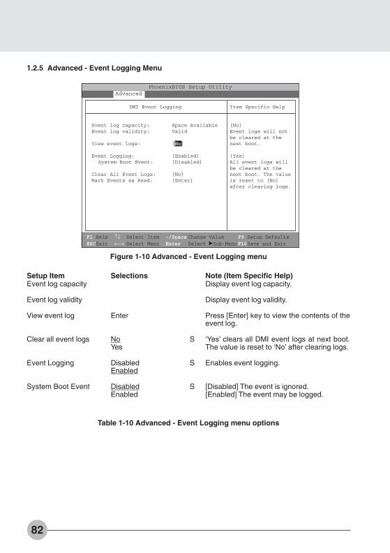
82
Figure 1-10 Advanced - Event Logging menu
1.2.5 Advanced - Event Logging Menu
Setup ItemEvent log capacity
Event log validity
View event log
Clear all event logs
Event Logging
System Boot Event
Selections
Enter
NoYes
DisabledEnabled
DisabledEnabled
Note (Item Specific Help)Display event log capacity.
Display event log validity.
Press [Enter] key to view the contents of theevent log.
‘Yes’ clears all DMI event logs at next boot.The value is reset to ‘No’ after clearing logs.
Enables event logging.
[Disabled] The event is ignored.[Enabled] The event may be logged.
S
S
S
Table 1-10 Advanced - Event Logging menu options
F1 Help ↑↓ Select Item -/Space Change Value F9 Setup DefaultsESCExit ←→ Select Menu Enter Select :Sub-MenuF10Save and Exit
PhoenixBIOS Setup UtilityMain Advanced Security Power Boot Info Exit
DMI Event Logging
Event log capacity: Space AvailableEvent log validity: Valid
View event logs: [No]
Event Logging: [Enabled]System Boot Event: [Disabled]
Clear All Event Logs: [No]Mark Events as Read: [Enter]
Item Specific Help
[No]Event logs will notbe cleared at thenext boot.
[Yes]All event logs willbe cleared at thenext boot. The valueis reset to [No]after clearing logs.
Bis Sec 3 (80-87) 01/11/1999, 15:1182
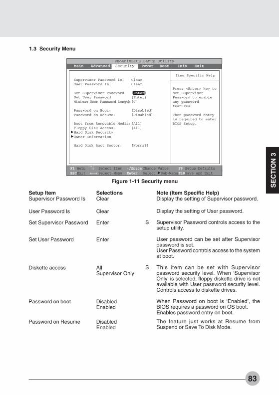
83
SE
CT
ION
3
1.3 Security Menu
Setup ItemSupervisor Password Is
User Password Is
Set Supervisor Password
Set User Password
Diskette access
Password on boot
Password on Resume
SelectionsClear
Clear
Enter
Enter
AllSupervisor Only
DisabledEnabled
DisabledEnabled
Note (Item Specific Help)Display the setting of Supervisor password.
Display the setting of User password.
Supervisor Password controls access to thesetup utility.
User password can be set after Supervisorpassword is set.User Password controls access to the systemat boot.
This item can be set with Supervisorpassword security level. When ‘SupervisorOnly’ is selected, floppy diskette drive is notavailable with User password security level.Controls access to diskette drives.
When Password on boot is ‘Enabled’, theBIOS requires a password on OS boot.Enables password entry on boot.
The feature just works at Resume fromSuspend or Save To Disk Mode.
S
S
F1 Help ↑↓ Select Item -/Space Change Value F9 Setup DefaultsESCExit ←→ Select Menu Enter Select :Sub-MenuF10Save and Exit
PhoenixBIOS Setup UtilityMain Advanced Security Power Boot Info Exit
Supervisor Password Is: ClearUser Password Is: Clear
Set Supervisor Password [Enter]Set User Password [Enter]Minimum User Password Length [0]
Password on Boot: [Disabled]Password on Resume: [Disabled]
Boot from Removable Media:[All]Floppy Disk Access: [All]
:Hard Disk Security:Owner information
Hard Disk Boot Sector: [Normal]
Item Specific Help
Press <Enter> key toset SupervisorPassword to enableany passwordfeatures.
Then password entryis required to enterBIOS Setup.
Figure 1-11 Security menu
Bis Sec 3 (80-87) 01/11/1999, 15:1183
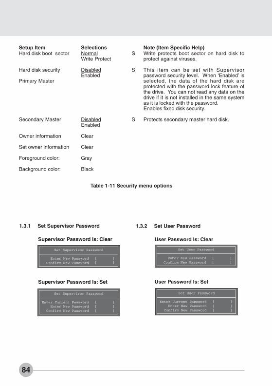
84
Setup ItemHard disk boot sector
Hard disk security
Primary Master
Secondary Master
Owner information
Set owner information
Foreground color:
Background color:
SelectionsNormalWrite Protect
DisabledEnabled
DisabledEnabled
Clear
Clear
Gray
Black
Note (Item Specific Help)Write protects boot sector on hard disk toprotect against viruses.
This item can be set with Supervisorpassword security level. When ‘Enabled’ isselected, the data of the hard disk areprotected with the password lock feature ofthe drive. You can not read any data on thedrive if it is not installed in the same systemas it is locked with the password.Enables fixed disk security.
Protects secondary master hard disk.
S
S
S
Table 1-11 Security menu options
1.3.1 Set Supervisor Password
Supervisor Password Is: Clear
Supervisor Password Is: Set
1.3.2 Set User Password
User Password Is: Clear
User Password Is: Set
Set Supervisor Password
Enter New Password [ ]Confirm New Password [ ]
Set Supervisor Password
Enter Current Password [ ]Enter New Password [ ]
Confirm New Password [ ]
Set User Password
Enter New Password [ ]Confirm New Password [ ]
Set User Password
Enter Current Password [ ]Enter New Password [ ]
Confirm New Password [ ]
Bis Sec 3 (80-87) 01/11/1999, 15:1184

85
SE
CT
ION
3
Figure 1-12 Power menu
1.4 Power Menu
Setup ItemPower Savings
Hard Disk Timeout
Display Timeout
SelectionsDisabledCustomizedMaximum PowerSavingsMaximum Performance
Off30 Seconds1 Minute2 Minutes4 Minutes6 Minutes8 Minutes10 Minutes15 Minutes20 Minutes
Off30 Seconds2 Minutes4 Minutes6 Minutes8 Minutes10 Minutes15 Minutes20 Minutes
Note (Item Specific Help)Select Power Management Mode. Choosingmodes changes system power managementsettings. Maximum Power Savings conservesthe greatest amount of system power whileMaximum Performance conserves power butallows greatest system performance. To alterthese settings, choose Customized. To turnoff power management, choose Disabled.
Amount of time the hard disk needs to beinactive before it is turned off.
Amount of time the user input devices needto be inactive before the screen is turned off.
F1 Help ↑↓ Select Item -/Space Change Value F9 Setup DefaultsESCExit ←→ Select Menu Enter Select :Sub-MenuF10Save and Exit
PhoenixBIOS Setup UtilityMain Advanced Security Power Boot Info Exit
Power Savings: [Customized]Hard Disk Timeout: [Off]Display Timeout: [Off]Standby Timeout: [4 Minutes]Auto Suspend Timeout: [15 Minutes]
Suspend Mode: [Suspend]Auto Save To Disk: [Off]
Resume On Modem Ring: [Off]Resume On Time: [Off]Resume Time: [00:00:00]
:Advanced Features
Item Specific Help
Select PowerManagement Mode.Choosing modeschanges system powermanagement settings.Maximum Power Savingsconserves thegreatest amount ofsystem power whileMaximum Performanceconserves power butallows greatestsystem performance.To alter thesesettings, chooseCustomize. To turnoff power management,choose Disable.
Bis Sec 3 (80-87) 01/11/1999, 15:1185
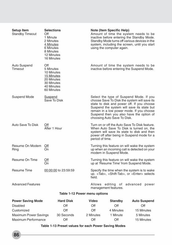
86
Setup ItemStandby Timeout
Auto SuspendTimeout
Suspend Mode
Auto Save To Disk
Resume On ModemRing
Resume On Time
Resume Time
Advanced Features
SelectionsOff1 Minute2 Minutes4 Minutes6 Minutes8 Minutes12 Minutes16 Minutes
Off5 Minutes10 Minutes15 Minutes20 Minutes30 Minutes40 Minutes60 Minutes
SuspendSave To Disk
OffAfter 1 Hour
OffOn
OffOn
00:00:00 to 23:59:59
Note (Item Specific Help)Amount of time the system needs to beinactive before entering the Standby Mode.Standby Mode turns off various devices in thesystem, including the screen, until you startusing the computer again.
Amount of time the system needs to beinactive before entering the Suspend Mode.
Select the type of Suspend Mode. If youchoose Save To Disk the system will save itsstate to disk and power off. If you chooseSuspend the system will save its state butremain in a low power mode. If you chooseSuspend then you also have the option ofchoosing Auto Save To Disk.
Turn on or off the Auto Save To Disk feature.When Auto Save To Disk is turned on, thesystem will save its state to disk and thenpower off after being in Suspend mode for aperiod of time.
Turning this feature on will wake the systemup when an incoming call is detected on yourmodem in Suspend Mode.
Turning this feature on will wake the systemup at ‘Resume Time’ from Suspend Mode.
Specify the time when the system is to wakeup. <Tab>, <Shift-Tab>, or <Enter> selectsfield.
Allows editing of advanced powermanagement features.
Table 1-12 Power menu options
Power Saving Mode Hard Disk Video Standby Auto SuspendDisabled Off Off Off OffCustomized Off Off 4 Minutes 15 MinutesMaximum Power Savings 30 Seconds 2 Minutes 1 Minute 5 MinutesMaximum Performance Off Off Off 15 Minutes
Table 1-13 Preset values for each Power Saving Modes
Bis Sec 3 (80-87) 01/11/1999, 15:1186

87
SE
CT
ION
3
Figure 1-13 Power - Advance Features menu
Setup ItemSUS/RES Switch
Lid Closure Suspend
Lid Open Resume
Resume On LAN
Auto Suspend on Undock
Serial Mouse Activity
SelectionsDisabledEnabled
OffOn
OffOn
OffOn
DisabledEnabledAlways Enabled
Note (Item Specific Help)Set the SUS/RES Switch.
Set the Lid Closure Suspend.
Set the Lid Open Resumes
Turning this feature on will wake the systemup when the internal LAN device receives amagic packet in suspend mode.
[Disabled] Never enter suspend mode aftereject automatically.[Auto] Only enter suspend mode after eject ifthe notebook lid id closed.[Always Enabled] Always enter suspend modeafter eject.
Turning this feature on will wake the video upfrom standby mode when external serialconnector activity is detected.
1.4.1 Power - Advanced Features Modes
Table 1-14 Power - Advanced Features menu options
F1 Help ↑↓ Select Item -/Space Change Value F9 Setup DefaultsESCExit ←→ Select Menu Enter Select :Sub-MenuF10Save and Exit
PhoenixBIOS Setup UtilityMain Advanced Security Power Boot Info Exit
Advanced Features
Suspend/Resume Switch: [Enabled]Lid Closure Suspend: [On]Lid Open Resume: [On]Resume On LAN: [Off]Serial Mouse Activity: [Disabled]Auto Suspend on Undock: [Disabled]
Item Specific Help
Configures theSuspend/Resumeswitch.
Bis Sec 3 (80-87) 01/11/1999, 15:1187
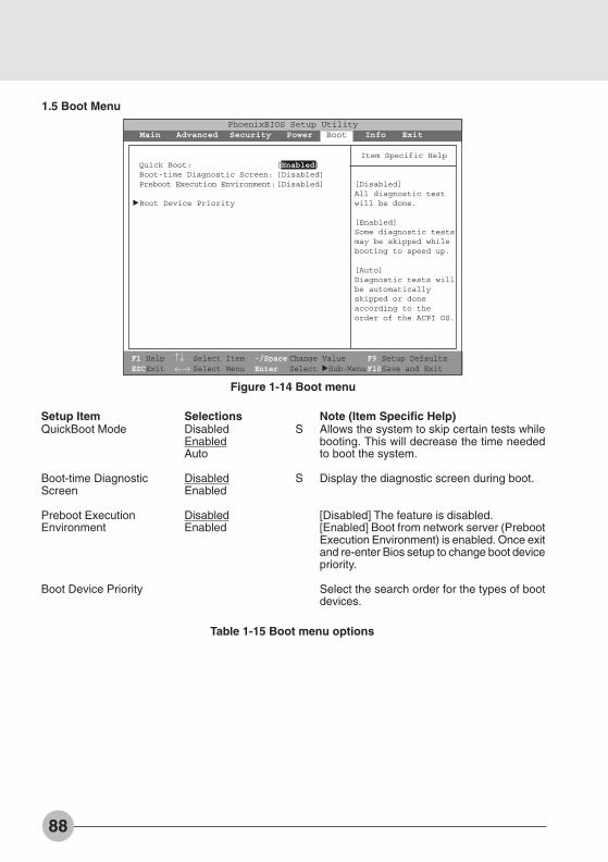
88
Figure 1-14 Boot menu
Setup ItemQuickBoot Mode
Boot-time DiagnosticScreen
Preboot ExecutionEnvironment
Boot Device Priority
SelectionsDisabledEnabledAuto
DisabledEnabled
DisabledEnabled
Note (Item Specific Help)Allows the system to skip certain tests whilebooting. This will decrease the time neededto boot the system.
Display the diagnostic screen during boot.
[Disabled] The feature is disabled.[Enabled] Boot from network server (PrebootExecution Environment) is enabled. Once exitand re-enter Bios setup to change boot devicepriority.
Select the search order for the types of bootdevices.
S
S
Table 1-15 Boot menu options
1.5 Boot Menu
F1 Help ↑↓ Select Item -/Space Change Value F9 Setup DefaultsESCExit ←→ Select Menu Enter Select :Sub-MenuF10Save and Exit
PhoenixBIOS Setup UtilityMain Advanced Security Power Boot Info Exit
Quick Boot: [Enabled]Boot-time Diagnostic Screen: [Disabled]Preboot Execution Environment:[Disabled]
:Boot Device Priority
Item Specific Help
[Disabled]All diagnostic testwill be done.
[Enabled]Some diagnostic testsmay be skipped whilebooting to speed up.
[Auto]Diagnostic tests willbe automaticallyskipped or doneaccording to theorder of the ACPI OS.
Bis Sec 3 (88-95) 01/11/1999, 15:1188

89
SE
CT
ION
3
Figure 1-15 Boot - Boot Device Priority menu
1.5. 1 Boot - Boot Device Priority Menu
Setup ItemBootable devices available are listed. Thefollowing devices will appear depending onthe hardware configuration.
[Floppy Disk Drive][Hard Drive][ATAPI CD-ROM Drive]
Note (Item Specific Help)Use <↑> or <↓> to select a device, then press<+> or <Space> to move it up the list, or <–>to move it down the list. Press <Esc> to exitthis menu.
Table 1-16 Boot - Boot menu DevicePriority options
1.5. 1.1 Boot Menu at POSTThe following pop up menu will appear when you hit the F12 key during POST. The device list in thispop up menu are same as the list in the Boot Device Priority menu.
F1 Help ↑↓ Select Item -/Space Change Value F9 Setup DefaultsESCExit ←→ Select Menu Enter Select :Sub-MenuF10Save and Exit
PhoenixBIOS Setup UtilityMain Advanced Security Power Boot Info Exit
Boot Device Priority
+Floppy Disk Drive+Hard Disk Drive
ATAPI CD-ROM Drive
Item Specific Help
The top device hasthe highest priority.
<Enter> expands orcollapses deviceswith a + or -.<Ctrl+Enter> expandsall.<↑> or <↓> select adevice.<+>/<Space> or <->move the device up ordown.<Shift+1> enables ordisables adevice.
Boot Menu
1. Floppy Disk Drive2. Hard Drive3. ATAPI CD-ROM Drive
<Enter Setup>
Bis Sec 3 (88-95) 01/11/1999, 15:1189
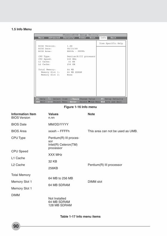
90
Information ItemBIOS Version
BIOS Date
BIOS Area
CPU Type
CPU Speed
L1 Cache
L2 Cache
Total Memory
Memory Slot 1
Memory Slot 1
DIMM
Valuesn.nn
MM/DD/YYYY
xxxxh – FFFFh
Pentium(R) III proces-sorIntel(R) Celeron(TM)processor
XXX MHz
32 KB
256KB
64 MB to 256 MB
64 MB SDRAM
Not Installed64 MB SDRAM128 MB SDRAM
Note
This area can not be used as UMB.
Pentium(R) III processor
DIMM slot
1.5 Info Menu
Figure 1-16 Info menu
F1 Help ↑↓ Select Item -/Space Change Value F9 Setup DefaultsESCExit ←→ Select Menu Enter Select :Sub-MenuF10Save and Exit
PhoenixBIOS Setup UtilityMain Advanced Security Power Boot Info Exit
BIOS Version: 1.XXBIOS Date: 08/10/99BIOS Area: E800h - FFFFh
CPU Type: Pentium(R)III processorCPU Speed: 500 MHzL1 Cache: 32 KBL2 Cache: 256 KB
Total Memory: 64 MBMemory Slot 1: 64 MB SDRAMMemory Slot 2: None
Item Specific Help
Table 1-17 Info menu items
Bis Sec 3 (88-95) 01/11/1999, 15:1190
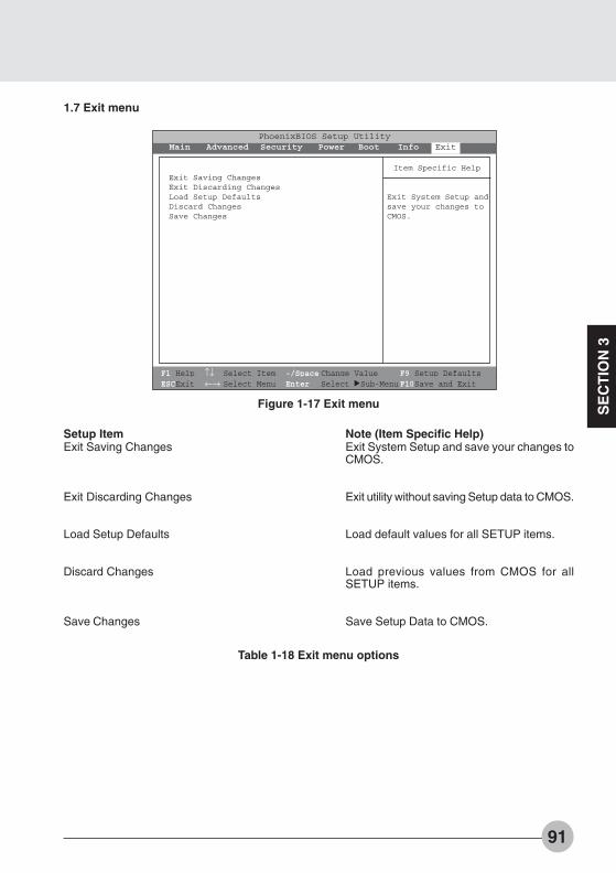
91
SE
CT
ION
3
Setup ItemExit Saving Changes
Exit Discarding Changes
Load Setup Defaults
Discard Changes
Save Changes
Note (Item Specific Help)Exit System Setup and save your changes toCMOS.
Exit utility without saving Setup data to CMOS.
Load default values for all SETUP items.
Load previous values from CMOS for allSETUP items.
Save Setup Data to CMOS.
1.7 Exit menu
Figure 1-17 Exit menu
Table 1-18 Exit menu options
F1 Help ↑↓ Select Item -/Space Change Value F9 Setup DefaultsESCExit ←→ Select Menu Enter Select :Sub-MenuF10Save and Exit
PhoenixBIOS Setup UtilityMain Advanced Security Power Boot Info Exit
Exit Saving ChangesExit Discarding ChangesLoad Setup DefaultsDiscard ChangesSave Changes
Item Specific Help
Exit System Setup andsave your changes toCMOS.
Bis Sec 3 (88-95) 01/11/1999, 15:1191
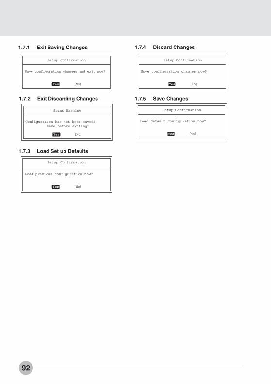
92
1.7.1 Exit Saving Changes
1.7.2 Exit Discarding Changes
1.7.4 Discard Changes
1.7.5 Save Changes
1.7.3 Load Set up Defaults
Setup Confirmation
Load default configuration now?
[Yes] [No]
Setup Confirmation
Save configuration changes and exit now?
[Yes] [No]
Setup Warning
Configuration has not been saved!Save before exiting?
[Yes] [No]
Setup Confirmation
Load previous configuration now?
[Yes] [No]
Setup Confirmation
Save configuration changes now?
[Yes] [No]
Bis Sec 3 (88-95) 01/11/1999, 15:1192

93
SE
CT
ION
3
General HelpSetup changes system behavior by modifying the BIOSconfiguration. Selecting incorrect values maycause system boot failure; load Setup Default values torecover.
<Up/Down> arrows select fields in current menu.<PgUp/PgDn> moves to previous/next page on scrollable menus.<Home/End> moves to top/bottom item of current menu.
Within a field, <F5> or <-> selects next lower value and<F6>, <+>, or <Space> selects next higher value.
<Left/Right> arrows select menus on menu bar.<Enter> displays more options for items marked with _.
<F9> loads factory installed Setup Default values.<F10> saves current settings and exits Setup.
<Esc> or <Alt-X> exits Setup; in sub-menus, pressing thesekeys returns to the previous menu.
<F1> or <Alt-H> displays General Help (this screen).
1.8 General Help
Figure 1-18 General Help
Table 1-19 Entire Text of General Help
F1 Help ↑↓ Select Item -/Space Change Value F9 Setup DefaultsESCExit ←→ Select Menu Enter Select ➧Sub-Menu F10Save and Exit
System Time: [12:34:56]System Date: [06/02/1999]
Legacy Diskette A: [1.44/1.25 MB 31/2”]
:Primary Master: [FUJITSU MHA2043AT]:Secondary Master: [None]:Secondary Master: [None]
System Memory: 640MBExtended Memory: 31MB
:Memory Cache
Language: [English (US)]
PhoenixBIOS Setup UtilityMain Advanced Security Power Boot Info Exit
Item Specific Help
<Tab>, <Shift-Tab oror <Enter> selectld.
Main
General Help
Setup changes system behavior by modifying the BIOSconfiguration. Selecting incorrect values maycause system boot failure; load Setup Default values torecover.
<Up/Down> arrows select fields in current menu.<Pgup/PgDn> moves to previous/next page on scrollablemenus.<Home/End> moves to top/bottom item of current menu.
Within a field, <F5> or <–> selects next lower value and<F6>, <+>, or <Space> selects next higher value.
[Continue]
:
Bis Sec 3 (88-95) 01/11/1999, 15:1193
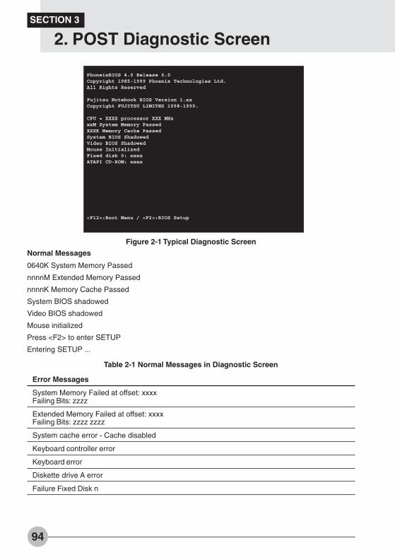
94
Table 2-1 Normal Messages in Diagnostic Screen
Figure 2-1 Typical Diagnostic Screen
Normal Messages
0640K System Memory Passed
nnnnM Extended Memory Passed
nnnnK Memory Cache Passed
System BIOS shadowed
Video BIOS shadowed
Mouse initialized
Press <F2> to enter SETUP
Entering SETUP ...
Error Messages
System Memory Failed at offset: xxxxFailing Bits: zzzz
Extended Memory Failed at offset: xxxxFailing Bits: zzzz zzzz
System cache error - Cache disabled
Keyboard controller error
Keyboard error
Diskette drive A error
Failure Fixed Disk n
PhoneixBIOS 4.0 Release 6.0Copyright 1985-1999 Phoenix Technologies Ltd.All Rights Reserved
Fujitsu Notebook BIOS Version 1.xxCopyright FUJITSU LIMITED 1998-1999.
CPU = XXXX processor XXX MHzxxM System Memory PassedXXXK Memory Cache PassedSystem BIOS ShadowedVideo BIOS ShadowedMouse InitializedFixed disk 0: xxxxATAPI CD-ROM: xxxx
<F12>:Boot Menu / <F2>:BIOS Setup
SECTION 3
2. POST Diagnostic Screen
Bis Sec 3 (88-95) 01/11/1999, 15:1194
95
SE
CT
ION
3
Error Messages
System timer error
Real time clock error
System CMOS checksum bad - Default configuration used
Previous boot incomplete - Default configuration used
Press <F1> to resume,<F2> to Setup
Check date and time settings
Password locked: Fixed Disk n
No Save To Disk partition or file exists on Fixed Disk- Save To Disk features is disabled.
Not enough Save To Disk partition or file exists on FixedDisk.- Save To Disk feature is disabled.
Hard Disk Drive is not installed.- Save To Disk feature is disabled.
Unknown Save To Disk error.- Save To Disk feature is disabled.
Hard disk sector read function failed.- Save To Disk feature is disabled.
Hard disk sector write function failed.- Save To Disk feature is disabled.
Save To Disk partition or file corrupted.- Save To Disk feature is disabled.
Fixed Disk is not installed. Cannot restore from disk.To restore from disk : turn off system, install originalfixed disk and reboot.Press <F1> to continue to boot without save to diskdata.
Fixed Disk has been changed. Cannot restore from disk.To restore from disk : turn off system, install original fixeddisk and reboot.Press <F1> to continue to boot without save to disk data.
Table 2-2 Error Messages in Diagnostic Screen
Bis Sec 3 (88-95) 01/11/1999, 15:1195

96
Sec
tio
n 4
This section explains what to do when trou-ble occurs with this computer and whenmessages are displayed. Read this sectionas the necessity arises.
SECTIONSECTIONSECTIONSECTIONSECTIONSECTIONSECTIONSECTIONSECTIONSECTION
4444444444
Bis Sec 4 (96-101) 01/11/1999, 15:1196

97
SE
CT
ION
4
1. When This Happens
When you are having trouble with this computer, there is something you think is strange, orthere is something you want to do, but do not know how. This section is divided into relateditems.
The power does not come on.
Checkpoint
Is the AC adaptor connected?
Is the battery charged?
Has the computer been leftunused for a long time?
Cause and Solution
When using this computer for the first time after purchase, thebattery is not yet charged, so you must connect the AC adaptorand turn on the SUS/RES button.
If a beep is heard when the main switch is turned on, then thebattery is running low (LOW BATTERY). Connect the ACadaptor.
When using the computer for the first time after leaving it unusedfor a long time, connect the AC adaptor and switch on the mainswitch to switch on the power.
Nothing displayed on the LCD panel
Checkpoint
Is displayed on the LCDpanel?
Is anything displayed on thestatus indicator LCD?
Cause and Solution
• DisplayedAdjust the brightness and darkness with the [Fn] + [F6] / [F7]keys.
• Flashing or not displayedPress the SUS/RES switch to put the computer into operatingmode.
• When the icon is off on the status indicator LCD.Press the SUS/RES button to put the computer into operatingmode. Check if the battery is charged. If it is not charged,connect the AC adaptor and charge it.If you are already using this computer with the AC adaptorconnected, check that it is correctly plugged into the powersocket and into the computer.
Connect the AC adaptor and press the SUS/RES button.
SECTION 4
Bis Sec 4 (96-101) 01/11/1999, 15:1197

98
Checkpoint
Have you been pressing anyof the keys?
Is it set to output to the CRT?
Cause and Solution
On this computer, if the power management functions are setand no key is pressed for a certain period of time, the CPU stopsand the LCD panel backlight goes out. (In this state, pressingany key lights up the backlight again.) If the computer stops toofrequently, change the BIOS setup settings.
Switch over to the LCD display with the [Fn] + [F10] keys.
LCD panel hard to read.
Checkpoint
Is the control adjusted?
Cause and Solution
Adjust the brightness and contrast with the [Fn] + [F6] / [F7]keys.
Battery is not charged.
Checkpoint
Is the AC adaptor connected?
Is the battery overheated(The on the LCDdisplay flashes.)?
Is the computer too cold(The on the LCDdisplay flashes.)?
Was the charging stoppedmidway?
Cause and Solution
Check that the AC adaptor is correctly plugged into the powersocket and into the computer.
If the ambient temperature is high and the battery temperaturebecomes too high during use, the battery protection functionmay be triggered to stop the charging.
If the battery temperature falls too low, the battery protectionfunction may be triggered to stop the charging.
If you use the computer and disconnect the AC adaptor betweenthe start of charging and the time the LCD turns off, thebattery will not become fully charged, Once you start chargingdo not remove the AC adapter until the LCD turns off.
The remaining battery charge indicator does not stop flashing.
Checkpoint
Is the battery connectedcorrectly?
Is the battery low?
Cause and Solution
Check that the battery is connected correctly. If it is connectedcorrectly, there is an abnormality in the battery pack, so replacethe battery pack.
Attach the AC adaptor and charge the battery.
Bis Sec 4 (96-101) 01/11/1999, 15:1198
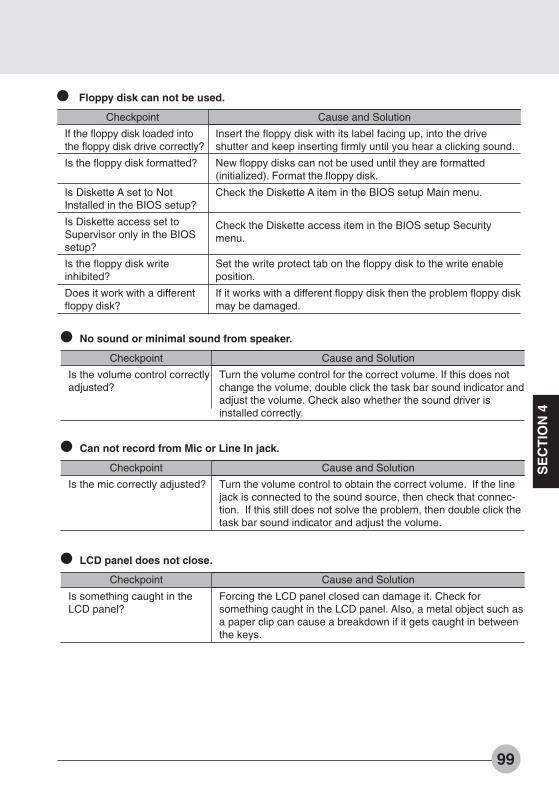
99
SE
CT
ION
4
Floppy disk can not be used.
Checkpoint
If the floppy disk loaded intothe floppy disk drive correctly?
Is the floppy disk formatted?
Is Diskette A set to NotInstalled in the BIOS setup?
Is Diskette access set toSupervisor only in the BIOSsetup?
Is the floppy disk writeinhibited?
Does it work with a differentfloppy disk?
Cause and Solution
Insert the floppy disk with its label facing up, into the driveshutter and keep inserting firmly until you hear a clicking sound.
New floppy disks can not be used until they are formatted(initialized). Format the floppy disk.
Check the Diskette A item in the BIOS setup Main menu.
Check the Diskette access item in the BIOS setup Securitymenu.
Set the write protect tab on the floppy disk to the write enableposition.
If it works with a different floppy disk then the problem floppy diskmay be damaged.
LCD panel does not close.
Checkpoint
Is something caught in theLCD panel?
Cause and Solution
Forcing the LCD panel closed can damage it. Check forsomething caught in the LCD panel. Also, a metal object such asa paper clip can cause a breakdown if it gets caught in betweenthe keys.
Can not record from Mic or Line In jack.
Checkpoint
Is the mic correctly adjusted?
No sound or minimal sound from speaker.
Checkpoint
Is the volume control correctlyadjusted?
Cause and Solution
Turn the volume control for the correct volume. If this does notchange the volume, double click the task bar sound indicator andadjust the volume. Check also whether the sound driver isinstalled correctly.
Cause and Solution
Turn the volume control to obtain the correct volume. If the linejack is connected to the sound source, then check that connec-tion. If this still does not solve the problem, then double click thetask bar sound indicator and adjust the volume.
Bis Sec 4 (96-101) 01/11/1999, 15:1199
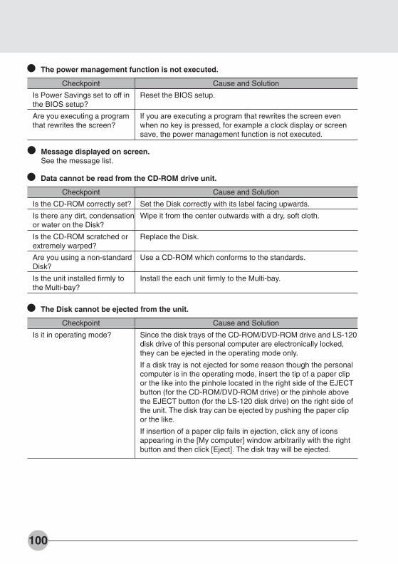
100
The power management function is not executed.
Checkpoint
Is Power Savings set to off inthe BIOS setup?
Are you executing a programthat rewrites the screen?
Cause and Solution
Reset the BIOS setup.
If you are executing a program that rewrites the screen evenwhen no key is pressed, for example a clock display or screensave, the power management function is not executed.
Message displayed on screen.See the message list.
The Disk cannot be ejected from the unit.
Checkpoint
Is it in operating mode?
Cause and Solution
Since the disk trays of the CD-ROM/DVD-ROM drive and LS-120disk drive of this personal computer are electronically locked,they can be ejected in the operating mode only.
If a disk tray is not ejected for some reason though the personalcomputer is in the operating mode, insert the tip of a paper clipor the like into the pinhole located in the right side of the EJECTbutton (for the CD-ROM/DVD-ROM drive) or the pinhole abovethe EJECT button (for the LS-120 disk drive) on the right side ofthe unit. The disk tray can be ejected by pushing the paper clipor the like.
If insertion of a paper clip fails in ejection, click any of iconsappearing in the [My computer] window arbitrarily with the rightbutton and then click [Eject]. The disk tray will be ejected.
Data cannot be read from the CD-ROM drive unit.
Checkpoint
Is the CD-ROM correctly set?
Is there any dirt, condensationor water on the Disk?
Is the CD-ROM scratched orextremely warped?
Are you using a non-standardDisk?
Is the unit installed firmly tothe Multi-bay?
Cause and Solution
Set the Disk correctly with its label facing upwards.
Wipe it from the center outwards with a dry, soft cloth.
Replace the Disk.
Use a CD-ROM which conforms to the standards.
Install the each unit firmly to the Multi-bay.
Bis Sec 4 (96-101) 01/11/1999, 15:11100

Fujitsu PC (Asia) Pte Ltd200 Pandan Loop#05-03 Pantech 21The Computer CentreSingapore 128388Tel: 65-776 0688Fax: 65-776 0788
Fujitsu PC (Asia) Pte Ltd(Malaysia Branch)8th Floor Wisma DamansaraJalan Semantan50490 Kuala LumpurMalaysiaTel: 603-253 3997Fax: 603-253 4245
Website : www.fujitsu-pc-asia.com
Bis Sec 4 (96-101) 01/11/1999, 15:11101