Microsoft Exchange 2010 Deployment Guide · About This Guide This guide details the configuration...
32
Microsoft Exchange 2010 Deployment Guide Copyright © 2012 Loadbalancer.org, Inc. 1
Transcript of Microsoft Exchange 2010 Deployment Guide · About This Guide This guide details the configuration...
Microsoft Exchange 2010Deployment Guide
Copyright © 2012 Loadbalancer.org, Inc.
1

Table of Contents
About This Guide.............................................................................................................................................. 4Appliances Supported.................................................................................................................................. 4Microsoft Exchange Software Versions Supported......................................................................................4Loadbalancer.org Software Versions Supported..........................................................................................4
Exchange Server 2010..................................................................................................................................... 5Exchange 2010 Server Roles........................................................................................................................... 5
Client Access Server.................................................................................................................................... 5Hub Transport Server.................................................................................................................................. 5Mailbox Server / Database Availability Group’s (DAG)................................................................................6
Load Balancing Exchange................................................................................................................................ 6The Basics................................................................................................................................................... 6
Which Roles?......................................................................................................................................... 6Virtual Server Requirements................................................................................................................... 6Persistence (aka Server Affinity).............................................................................................................7
Port Requirements....................................................................................................................................... 7Deployment Architecture................................................................................................................................... 8Exchange 2010 Configuration........................................................................................................................... 9
CAS Array.................................................................................................................................................... 9Static RPC Ports........................................................................................................................................ 10
The RPC Client Access Service............................................................................................................10The Exchange Address Book Service (SP1 Installed)..........................................................................11
Send & Receive Connectors...................................................................................................................... 12Send Connector.................................................................................................................................... 12Receive Connector............................................................................................................................... 12
Microsoft Outlook Client Configuration......................................................................................................13Loadbalancer.org Appliance – The Basics......................................................................................................14
Load Balancer Deployment Method...........................................................................................................14Accessing the Web User Interface (WUI)..................................................................................................14
V6......................................................................................................................................................... 14V7......................................................................................................................................................... 15
Loadbalancer.org Appliance - Configuring for Exchange 2010.......................................................................16Configure Layer 7 Global Settings.............................................................................................................16Configuring the Virtual & Real Servers......................................................................................................17
VIP1 - CAS Role HTTP & HTTPS Services..........................................................................................17a) Setting up the Virtual Server........................................................................................................17b) Setting up the Real Servers.........................................................................................................19
VIP2 - CAS Role RPC Services............................................................................................................20a) Setting up the Virtual Server........................................................................................................20b) Setting up the Real Servers.........................................................................................................22
VIP3 - CAS Role IMAP4 or POP3 Services..........................................................................................23a) Setting up the Virtual Server........................................................................................................23b) Setting up the Real Servers.........................................................................................................25
VIP4 - HT Role SMTP Services............................................................................................................26a) Setting up the Virtual Server........................................................................................................26b) Setting up the Real Servers.........................................................................................................28
Finalizing the Configuration....................................................................................................................... 29Appliance Specifications / Concurrent Exchange Users............................................................................29
3rd Party Testing Tool..................................................................................................................................... 29Technical Support........................................................................................................................................... 29
2

Conclusion...................................................................................................................................................... 29Appendix......................................................................................................................................................... 30
1 - Configuring the Load balancer using a single VIP for all CAS Services...............................................302 - Limiting inbound SMTP Connections using Firewall Rules...................................................................313 - Using HTTP Cookie Persistence for OWA Users..................................................................................314 - Enabling full Transparency using Tproxy..............................................................................................32
3
About This Guide
This guide details the configuration of Loadbalancer.org appliances for deployment with Microsoft Exchange 2010.
For an introduction to setting up the appliance as well as more detailed technical information, please refer to our quick-start guide and administration manual which are available at the following link :
http://www.loadbalancer.org/downloads.php
(the documentation links are at the bottom of the page)
Appliances SupportedAll our products can used with Exchange 2010. The complete list of models is shown below:
• Enterprise R16
• Enterprise
• Enterprise MAX
• Enterprise 10G
• Enterprise VA
• Enterprise VA R16
For a full specification comparison of these models please refer to : http://www.loadbalancer.org/matrix.php
Microsoft Exchange Software Versions Supported
• Microsoft Exchange 2010
• Microsoft Exchange 2010 SP1
• Microsoft Exchange 2010 SP2
Loadbalancer.org Software Versions Supported
• v6.9, v6.10, v6.11, v6.12, v6.13, v6.14, v6.15, v6.16, v6.17, v6.18
• v7.2, v7.3, v7.3.1, v7.3.2
4
Exchange Server 2010Exchange 2010 is Microsoft's enterprise level messaging and collaboration server.
Exchange 2010 Server RolesSystem functionality is split into five role as shown in the following table. Mandatory roles are Mailbox, Client Access and Hub Transport. The Edge Transport and Unified Messaging roles are optional and depend on the infrastructure and operational requirements.
Role PurposeMailbox Server This server hosts mailboxes and public folders.
Client Access Server This is the server that hosts the client protocols, such as Post Office Protocol 3 (POP3), Internet Message Access Protocol 4 (IMAP4), Secure Hypertext Transfer Protocol (HTTPS), Outlook Anywhere, Availability service, and Autodiscover service. The Client Access Server also hosts Web services.
Unified Messaging Server This is the server that connects a Private Branch exchange (PBX) system to Exchange 2010.
Hub Transport Server This is the mail routing server that routes mail within the Exchange organization.
Edge Transport Server This is the mail routing server that typically sits at the perimeter of the topology and routes mail in to and out of the Exchange organization.
Client Access ServerThe Client Access Server Role also known as CAS, provides Exchange connectivity for all clients regardless of client type or protocol including Outlook Web App (aka OWA), ActiveSync, POP3, IMAP4, RPC Client Access (MAPI) and Outlook Anywhere (previously known as RPC over HTTP). Exchange now has a single common path through which all data access occurs.
Therefore, due to the critical nature of this role, it's common practice to implement load balancing and redundancy technologies to ensure availability.
Hub Transport ServerFor internal server to server mail traffic, HT servers are automatically load balanced by Exchange 2010 and there is no need to configure any type of load balancing mechanism to load balance the mail submission traffic among Exchange servers.
However, some sites may decide not to deploy an ET server. In this scenario, inbound SMTP mail is typically forwarded from a third party smart host directly to the HT server. Also, internal applications and systems often need to send email via Exchange and typically are only able to do so using an SMTP connection. To provide redundancy in these cases, additional load balancing & HA techniques are required to ensure availability of the HT role.
5

Mailbox Server / Database Availability Group’s (DAG)Exchange 2010 brings the ability to combine both CAS and HT roles on a mailbox server that is also configured as a DAG member. This permits a highly available solution using just two Exchange servers and one or two (configured as a clustered pair for added redundancy) Loadbalancer.org appliances. Another server is needed to act as the witness server, but this doesn’t need to be an Exchange server. It could be any Windows 2003/2008 file server within the environment.
DAG's utilize Microsoft Clustering Services which cannot be enabled on the same server as Microsoft Network Load Balancing (NLB). Therefore, using Microsoft NLB is not an option in this case. Using a Loadbalancer.org hardware appliance provides an ideal solution.
Load Balancing Exchange
The Basics
Which Roles?The CAS role does not have any built-in load balancing functionality. The HT role does provide load balancing functionality for server to server mail traffic, but not external SMTP traffic that arrives from other applications or from outside the organization directly to the HT server. Therefore, it is a common requirement to load balance both the CAS and HT roles. In some cases only the CAS role is load balanced. The exact load balancing requirements depend on the number of servers in use and how / where the roles are deployed.
Virtual Server RequirementsThere are a number of options when deciding on the number of VIPs required for the CAS and HT roles. This deployment guide presents two options -
Option 1 – Four VIPs (Used for the example configuration in this guide)
This method uses three VIPs for the CAS role, and one VIP for the HT role as follows:
1. CAS role – HTTPS & HTTP services
2. CAS role – RPC services
3. CAS role – IMAP4 or POP3 services (if used / required)
4. HT role – SMTP services
This method allows the settings for each VIP to be customized (e.g. persistence/affinity options) to suit the service being load balanced and also ensures more granular health-checks.
Typically, IMAP4 and POP3 are not required in an Exchange 2010 environment. This means that this VIP can normally be omitted.
6

Option 2 – Two VIPs
This method uses two VIPs - one VIP for all CAS services, and one VIP for the HT role. This is useful for rapid deployments and is recommended primarily for evaluation & testing. For details of this, please refer to section 1 in the Appendix.
Persistence (aka Server Affinity)Some Exchange 2010 protocols require affinity and others do not. For more details please refer to the following Microsoft Technet article: http://technet.microsoft.com/en-us/library/ff625248.aspx
For additional information on the various affinity options, please refer to the following Microsoft Technet article: http://technet.microsoft.com/en-us/library/ff625247.aspx#affinity
Summary of Persistence Requirements:
Persistence - Required Persistence – Recommended Persistence – Not RequiredOutlook Web App Outlook Anywhere Offline Address Book
Exchange Control Panel ActiveSync AutoDiscover
Exchange Web Service Address Book Service POP3
RPC Client Access Service Remote PowerShell IMAP4
For simplicity and consistency we recommend that source IP persistence is used for all protocols that require persistence between client and back-end server.
Note: If your Outlook Web App users pass through a NAT device to reach the load balancer then IP based persistence will not be appropriate since the source IP address will be the same for all users. This would cause all OWA sessions to be directed to the same backend CAS. In this situation, HTTP cookie persistence can be used. This requires the HTTPS traffic to be terminated on the load balancer to allow the cookie to be read. For more details on this, please refer to the Appendix.
Port RequirementsThe following table shows the port list that must be load balanced for the CAS and HT roles. Note that some services such as IMAP4 or POP3 may not be used in your environment.
TCP Port Role(s) Uses25 HT SMTP
80 CAS HTTP - various
110 CAS POP3 clients
135 CAS RPC end point mapper
143 CAS IMAP4 clients
443 CAS HTTPS - various
993 CAS Secure IMAP4 clients
995 CAS Secure POP3 clients
60200* CAS Static port for RPC client access service
60201* CAS Static port for Exchange address book service
HT = Hub Transport Server , CAS = Client Access Server
7
* These ports have been chosen as the static RPC ports. Microsoft recommends that any port within the range 59531 to 60554 should be used, and that the same ports should be used on all Client Access Servers within the same AD site.
For a full Exchange Server 2010 port list, please refer to the following Microsoft Technet article: http://technet.microsoft.com/en-us/library/bb331973.aspx
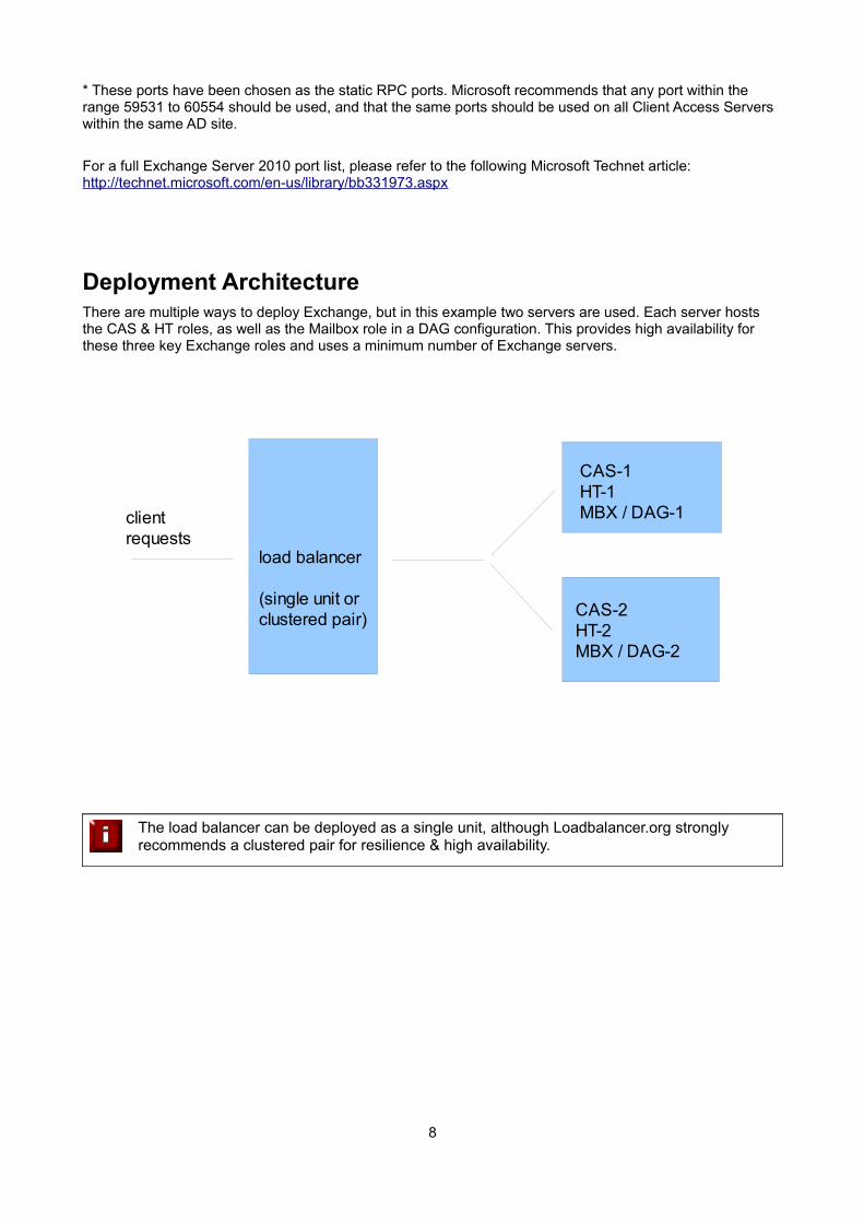
Deployment ArchitectureThere are multiple ways to deploy Exchange, but in this example two servers are used. Each server hosts the CAS & HT roles, as well as the Mailbox role in a DAG configuration. This provides high availability for these three key Exchange roles and uses a minimum number of Exchange servers.
The load balancer can be deployed as a single unit, although Loadbalancer.org strongly recommends a clustered pair for resilience & high availability.
8
load balancer
(single unit or clustered pair)
CAS-1HT-1MBX / DAG-1
CAS-2HT-2MBX / DAG-2
client requests
Exchange 2010 Configuration
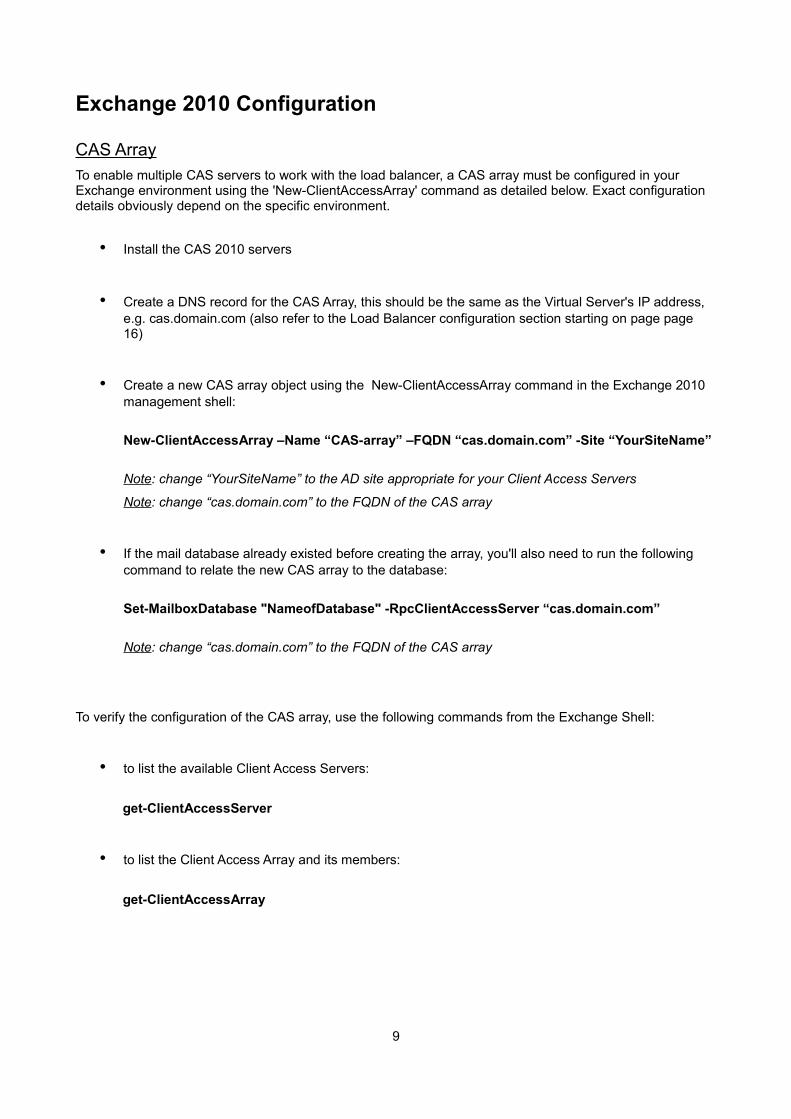
CAS ArrayTo enable multiple CAS servers to work with the load balancer, a CAS array must be configured in your Exchange environment using the 'New-ClientAccessArray' command as detailed below. Exact configuration details obviously depend on the specific environment.
• Install the CAS 2010 servers
• Create a DNS record for the CAS Array, this should be the same as the Virtual Server's IP address, e.g. cas.domain.com (also refer to the Load Balancer configuration section starting on page page 16)
• Create a new CAS array object using the New-ClientAccessArray command in the Exchange 2010 management shell:
New-ClientAccessArray –Name “CAS-array” –FQDN “cas.domain.com” -Site “YourSiteName”
Note: change “YourSiteName” to the AD site appropriate for your Client Access Servers
Note: change “cas.domain.com” to the FQDN of the CAS array
• If the mail database already existed before creating the array, you'll also need to run the following command to relate the new CAS array to the database:
Set-MailboxDatabase "NameofDatabase" -RpcClientAccessServer “cas.domain.com”
Note: change “cas.domain.com” to the FQDN of the CAS array
To verify the configuration of the CAS array, use the following commands from the Exchange Shell:
• to list the available Client Access Servers:
get-ClientAccessServer
• to list the Client Access Array and its members:
get-ClientAccessArray
9

Static RPC PortsBy default the RPC Client Access service and the Address Book Service on an Exchange 2010 Client Access Server uses the TCP End Point Mapper port (TCP/135) and the dynamic RPC port range (6005-59530) for outgoing connections when an Outlook clients establishes a connection to Exchange.
Since this would add complexity to the load balancers configuration, and would also uses substantially more on-board memory, it's recommended to configure static ports as described below.
If you later apply a service pack to your servers, re-check that the settings described in this section are still valid
The RPC Client Access ServiceTo set a static port for the RPC Client Access Service, open the registry on each CAS and navigate to:
HKEY_LOCAL_MACHINE\SYSTEM\CurrentControlSet\services\MSExchangeRPC
Here, you need to create a new key named ParametersSystem, and under this key create a new DWORD (32-bit) Value named TCP/IP Port as shown below. The Value for the DWORD should be the port number you want to use. Microsoft recommends you set this to a unique value between 59531 and 60554 and use the same value on all CAS.
In this deployment guide, the port used is 60200.
Note: Once this registry change has been made, restart the RPC Client Access Service to apply the new setting. This process must be completed on all CAS.
Note: If there is a possibility that these ports are already in use, for example if the server was serving clients prior to implementing these changes, then a reboot is recommended rather than a service restart.
10

The Exchange Address Book Service (SP1 Installed)To set a static port for the Address Book Service, open the registry on each CAS and navigate to:
HKEY_LOCAL_MACHINE\SYSTEM\CurrentControlSet\services\MSExchangeAB
Here, you need to create a new key named Parameters, and under this key create a new String Value named RpcTcpPort as shown below. Microsoft recommends you set this to a unique value between 59531 and 60554 and use the same value on all CAS.
In this deployment guide, the port used is 60201.
Note: Once this registry change has been made, restart the Address Book Service to apply the new setting. This process will need to be completed on all CAS.
Note: If there is a possibility that these ports are already in use, for example if the server was serving clients prior to implementing these changes, then a reboot is recommended rather than a service restart
Exchange Address Book Service (Pre SP1)
For Exchange 2010 without SP1, the static port for the Exchange Address Book service is configured in a different way. First, navigate to the following folder:
C:\Program Files\Microsoft\Exchange Server\V14\Bin
Using Notepad, open the file microsoft.exchange.addressbook.service.exe.config
Now change the value for the key RpcTcpPort to the port you want to use. The ports specified must be different than the port used for the RPC Client Access Service. In this deployment guide the port used is 60201.
IMPORTANT : Once the settings listed in this section have have been configured and the services have been restarted, verify that all servers are listening on these newly configured ports by using the following command in a command window on each Exchange server: netstat -an -p tcp
11

For more information on configuring & verifying static ports, please refer to the following Microsoft Technet article:
http://social.technet.microsoft.com/wiki/contents/articles/configure-static-rpc-ports-on-an-exchange-2010-client-access-server.aspx
Send & Receive ConnectorsIn cases where there is no Edge Transport server, the Hub Transport Server must be configured to accept and send mail. It is possible to send and receive directly to / from the Internet, although a more secure and typical configuration would be to use a 3rd party external smart host. To establish mail flow to and from the Internet through a Hub Transport server the basis steps required are:
1) Create a Send connector on the Hub Transport server to send e-mail to the Internet
2) Modify the default Receive connector to allow anonymous connections
Send Connector
• Open the Exchange Management Shell and run the following command:
New-SendConnector -Name "<Name for this send connector>" -Usage Internet -AddressSpaces "*" -SourceTransportServers "<Hub Transport Server Name>" -DNSRoutingEnabled:$true -UseExternalDNSServersEnabled:$true
Receive Connector
• Open the Exchange Management Shell and run the following command:
Set-ReceiveConnector -Name "Default Server Name" -Server "<Hub Transport Server Name>" -PermissionGroups AnonymousUsers,ExchangeUsers,ExchangeServers,ExchangeLegacyServers
Note: The exact configuration steps required depend on your environment. The steps listed above are provided as an example.
12
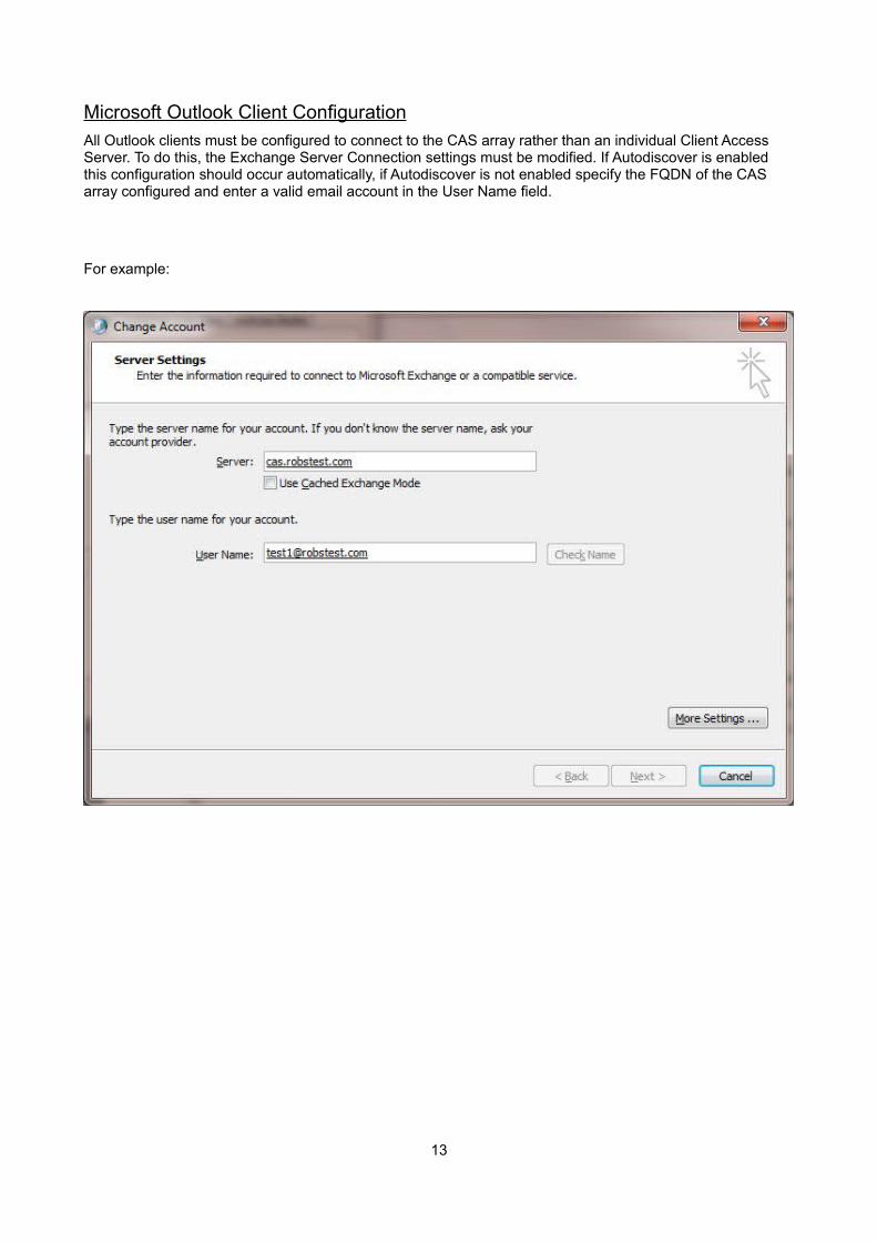
Microsoft Outlook Client ConfigurationAll Outlook clients must be configured to connect to the CAS array rather than an individual Client Access Server. To do this, the Exchange Server Connection settings must be modified. If Autodiscover is enabled this configuration should occur automatically, if Autodiscover is not enabled specify the FQDN of the CAS array configured and enter a valid email account in the User Name field.
For example:
13

Loadbalancer.org Appliance – The Basics
It's important to have a working Exchange 2010 environment first before implementing the load balancer
Load Balancer Deployment MethodAs with other Microsoft applications, the load balancer for Exchange 2010 is deployed in one-arm SNAT mode (Source Network Address Translation) at layer 7 using HAproxy This mode is recommended by Microsoft and also has the advantage that it requires no changes to the Exchange 2010 servers. Note that Haproxy is transparent which means that the clients actual source IP addresses are lost. If this is an issue, please refer to section 4 in the Appendix for details on using Tproxy. Transparency may also be an issue if you intend to limit inbound SMTP connections at the SMTP connector by IP address. For an alternative method using the load balancers on-board firewall, please refer to section 2 in the Appendix.
Note: The wizard should not be used since this will configure a Layer 4 Virtual Server which is not required in this case.
Accessing the Web User Interface (WUI)
The WUI can be accessed from a browser at: http://192.168.2.21:9080/lbadmin
(replace 192.168.2.21 with the IP address of your load balancer)
Username: loadbalancer
Password: loadbalancer
Once you have entered the logon credentials the Loadbalancer.org Web User Interface will be displayed.
V6
The figure below shows the V6.16 Web User Interface once logged in.
14

V7
The figure below shows the V7.3 Web User Interface once logged in.
Note: The setup instructions in the following sections cover both versions 6 and 7 of the Appliance. If there are any differences in the configuration steps between the versions, these are highlighted accordingly.
15

Loadbalancer.org Appliance - Configuring for Exchange 2010
Configure Layer 7 Global SettingsTo ensure that client connections remain open during periods of inactivity, the Clitimeout and Srvtimeout values must be changed from their default values of 43 seconds and 45 seconds respectively to 1 hour. To do this follow the steps below:
• V7 - Go to Edit Configuration > Layer 7 – Advanced Configuration
• V6 - Go to Edit Configuration > Global Settings
• Change clitimeout to 3600000 (i.e. 1 hour)
◦ Note : from v7.3.2 onwards this setting is named Client Timeout
• Change srvtimeout to 3600000 (i.e. 1 hour)
◦ Note : from v7.3.2 onwards this setting is named Server Timeout
• Click the Update button to save the settings
This step must be completed to avoid Outlook client timeout & reconnection issues that would otherwise occur within around one minute with unchanged default values
16

Configuring the Virtual & Real Servers
VIP1 - CAS Role HTTP & HTTPS Services
a) Setting up the Virtual Server
• V7 - Go to Edit Configuration > Layer 7 - Virtual Servers
• V6 - Go to Edit Configuration > Virtual Servers (HAProxy)
• Click [Add a new Virtual Server]
• Type an appropriate Label (name) for the Virtual Server, e.g. CAS-WEB
• V7 - Enter an appropriate IP address in the Virtual Server IP address field: e.g. 192.168.30.10
• V7 - Enter the following in the Virtual Server Ports field: 80,443
• V6 - Enter an appropriate IP address with port 80 in the Virtual Server field (e.g. 192.168.30.10:80)
• Change the Persistence Mode to 'Source IP'
• Click the Update button to save the settings
• Now click [Modify] next to the newly created Virtual Server
• V6 - In the Extra Ports field enter the additional port: 443
• Ensure that Layer 7 Protocol is set to 'Other TCP'
• V7 - Set the Balance Mode to Weighted Round Robin
• V6 - Set the Balance Mode to Round Robin
NOTE : Microsoft recommends that 'Round Robin' rather than 'Least Connection' should be used to help prevent over loading servers when they are brought online. This could occur if Least Connection was selected, since the load balancer would try to balance the number of connections across all real severs and therefore send all new requests to the new server. The trade off here is that using Round Robin will mean that server load may remain unbalanced for some time after bringing a new server into the active pool.
• Change Timeout to 60 (this sets the persistence timeout to 1 hour)
• Click the Update button to save the settings
Note: please refer to the reference screen shots on the following page
17
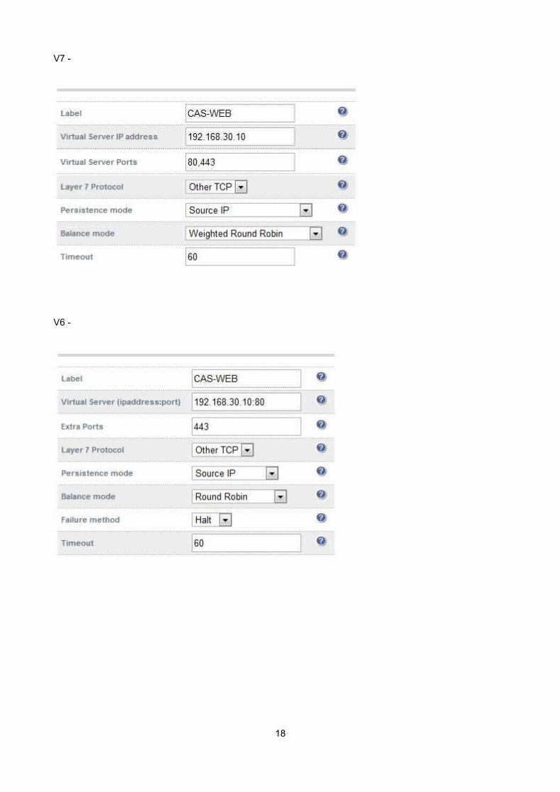
V7 -
V6 -
18

b) Setting up the Real Servers
• V7 - Go to Edit Configuration > Layer 7 - Real Servers
• V6 - Go to Edit Configuration > Real Servers (HAProxy)
• Click [Add a new Real Server] next to the CAS-HTTP&HTTPS Virtual Server
• Type an appropriate Label (name) for the server, e.g. CAS1
• V7 - Enter an appropriate IP address in the Real Server IP address field: e.g. 192.168.30.20
• V7 – Leave the Real Server Port field blank
• V6 - Enter an appropriate IP address in the Real Sever field without specifying a port (e.g. 192.168.30.20)
• Click the Update button to save the settings
• Now repeat for your other CAS server(s) that form part of the same VIP
V7 -
V6 -
NOTE: Because SNAT is a full proxy, any server in the cluster can be on any accessible subnet including across the Internet or WAN
19
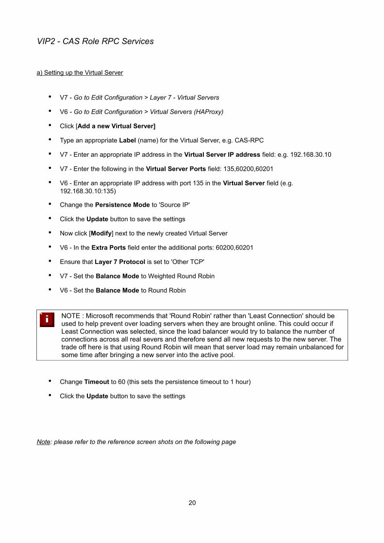
VIP2 - CAS Role RPC Services
a) Setting up the Virtual Server
• V7 - Go to Edit Configuration > Layer 7 - Virtual Servers
• V6 - Go to Edit Configuration > Virtual Servers (HAProxy)
• Click [Add a new Virtual Server]
• Type an appropriate Label (name) for the Virtual Server, e.g. CAS-RPC
• V7 - Enter an appropriate IP address in the Virtual Server IP address field: e.g. 192.168.30.10
• V7 - Enter the following in the Virtual Server Ports field: 135,60200,60201
• V6 - Enter an appropriate IP address with port 135 in the Virtual Server field (e.g. 192.168.30.10:135)
• Change the Persistence Mode to 'Source IP'
• Click the Update button to save the settings
• Now click [Modify] next to the newly created Virtual Server
• V6 - In the Extra Ports field enter the additional ports: 60200,60201
• Ensure that Layer 7 Protocol is set to 'Other TCP'
• V7 - Set the Balance Mode to Weighted Round Robin
• V6 - Set the Balance Mode to Round Robin
NOTE : Microsoft recommends that 'Round Robin' rather than 'Least Connection' should be used to help prevent over loading servers when they are brought online. This could occur if Least Connection was selected, since the load balancer would try to balance the number of connections across all real severs and therefore send all new requests to the new server. The trade off here is that using Round Robin will mean that server load may remain unbalanced for some time after bringing a new server into the active pool.
• Change Timeout to 60 (this sets the persistence timeout to 1 hour)
• Click the Update button to save the settings
Note: please refer to the reference screen shots on the following page
20

V7 -
V6 -
21

b) Setting up the Real Servers
• V7 - Go to Edit Configuration > Layer 7 - Real Servers
• V6 - Go to Edit Configuration > Real Servers (HAProxy)
• Click [Add a new Real Server] next to the CAS-RPC Virtual Server
• Type an appropriate Label (name) for the server, e.g. CAS1
• V7 - Enter an appropriate IP address in the Real Server IP address field: e.g. 192.168.30.20
• V7 – Leave the Real Server Port field blank
• V6 - Enter an appropriate IP address in the Real Sever field without specifying a port (e.g. 192.168.30.20)
• Click the Update button to save the settings
• Now repeat for your other CAS server(s) that form part of the same VIP
V7 -
V6 -
NOTE: Because SNAT is a full proxy, any server in the cluster can be on any accessible subnet including across the Internet or WAN
22

VIP3 - CAS Role IMAP4 or POP3 Services
a) Setting up the Virtual Server
Note: these steps show IMAP4 settings, for POP3 change the port numbers from 143 & 993 to 110 & 995
• V7 - Go to Edit Configuration > Layer 7 - Virtual Servers
• V6 - Go to Edit Configuration > Virtual Servers (HAProxy)
• Click [Add a new Virtual Server]
• Type an appropriate Label (name) for the Virtual Server, e.g. CAS-IMAP4
• V7 - Enter an appropriate IP address in the Virtual Server IP address field: e.g. 192.168.30.10
• V7 - Enter the following in the Virtual Server Ports field: 143,993
• V6 - Enter an appropriate IP address with port 143 in the Virtual Server field (e.g. 192.168.30.10:143)
• V6 – Change the Persistence Mode to None
• Click the Update button to save the settings
• Now click [Modify] next to the newly created Virtual Server
• V6 - In the Extra Ports field enter the additional ports: 993
• Ensure that Layer 7 Protocol is set to 'Other TCP'
• V7 - Set the Balance Mode to Weighted Round Robin
• V6 - Set the Balance Mode to Round Robin
NOTE : Microsoft recommends that 'Round Robin' rather than 'Least Connection' should be used to help prevent over loading servers when they are brought online. This could occur if Least Connection was selected, since the load balancer would try to balance the number of connections across all real severs and therefore send all new requests to the new server. The trade off here is that using Round Robin will mean that server load may remain unbalanced for some time after bringing a new server into the active pool.
• Click the Update button to save the settings
Note: persistence is not required for IMAP or POP3
Note: please refer to the reference screen shots on the following page
23

V7 -
V6 -
24
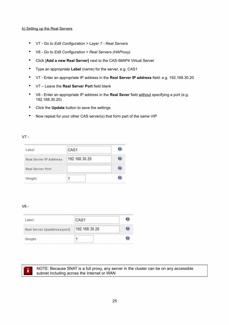
b) Setting up the Real Servers
• V7 - Go to Edit Configuration > Layer 7 - Real Servers
• V6 - Go to Edit Configuration > Real Servers (HAProxy)
• Click [Add a new Real Server] next to the CAS-IMAP4 Virtual Server
• Type an appropriate Label (name) for the server, e.g. CAS1
• V7 - Enter an appropriate IP address in the Real Server IP address field: e.g. 192.168.30.20
• V7 – Leave the Real Server Port field blank
• V6 - Enter an appropriate IP address in the Real Sever field without specifying a port (e.g. 192.168.30.20)
• Click the Update button to save the settings
• Now repeat for your other CAS server(s) that form part of the same VIP
V7 -
V6 -
NOTE: Because SNAT is a full proxy, any server in the cluster can be on any accessible subnet including across the Internet or WAN
25
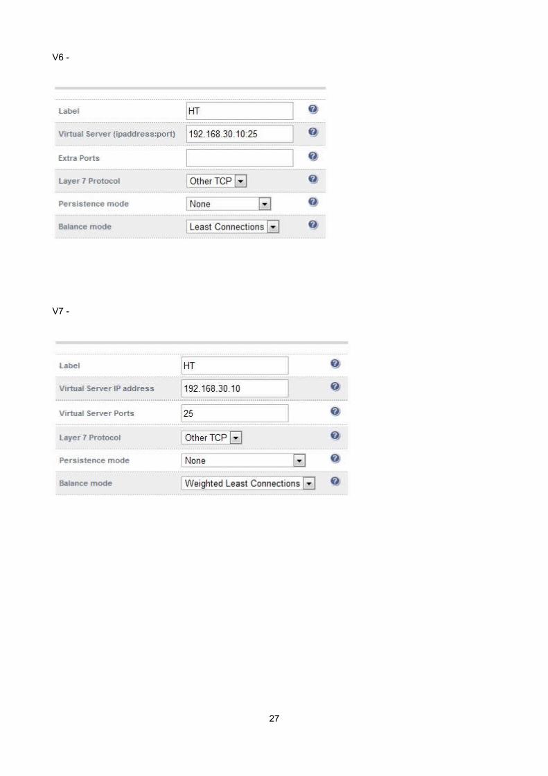
VIP4 - HT Role SMTP Services
a) Setting up the Virtual Server
• V7 - Go to Edit Configuration > Layer 7 - Virtual Servers
• V6 - Go to Edit Configuration > Virtual Servers (HAProxy)
• Click [Add a new Virtual Server]
• Type an appropriate Label (name) for the Virtual Server, e.g. HT
• V7 - Enter an appropriate IP address in the Virtual Server IP address field: e.g. 192.168.30.10
• V7 - Enter the following in the Virtual Server Ports field: 25
• V6 - Enter an appropriate IP address with port 25 in the Virtual Server field (e.g. 192.168.30.10:25)
• V6 – Change the Persistence Mode to None
• Click the Update button to save the settings
• Now click [Modify] next to the newly created Virtual Server
• Ensure that Layer 7 Protocol is set to 'Other TCP'
• V7 - Set the Balance Mode to Weighted Least Connection
• V6 - Set the Balance Mode to Least Connection
• Click the Update button to save the settings
Note: please refer to the reference screen shots on the following page
Note: since HAproxy is non-transparent - i.e. the source IP address is the IP of the load balancer rather than the actual client, it's not possible to setup the SMTP connector to accept/reject connections based on source IP address of the inbound connection.
If you want to control inbound connections on the load balancer, refer to section 2 of the Appendix for details on adding custom firewall rules.
It's also possible to configure the load balancer to work in transparent mode using Tproxy with HAproxy This requires a 2-Arm configuration where the VIPs and Exchange servers are located on different subnets. This would then allow IP rules to be configured on the Exchange connector. For more details on this refer to section 4 in the Appendix.
26
V6 -
V7 -
27

b) Setting up the Real Servers
• V7 - Go to Edit Configuration > Layer 7 - Real Servers
• V6 - Go to Edit Configuration > Real Servers (HAProxy)
• Click [Add a new Real Server] next to the HT Virtual Server
• Type an appropriate Label (name) for the server, e.g. HT1
• V7 - Enter an appropriate IP address in the Real Server IP address field: e.g. 192.168.30.20
• V7 – Enter an appropriate port in the Real Server Port field: i.e. 25
• V6 - Enter an appropriate IP address & port in the Real Sever field (e.g. 192.168.30.20:25)
• Click the Update button to save the settings
• Now repeat for your other HT server(s) that form part of the same VIP
V7 -
V6 -
NOTE: Because SNAT is a full proxy, any server in the cluster can be on any accessible subnet including across the Internet or WAN.
28

Finalizing the Configuration
To apply the new settings, HAProxy must be restarted as follows:
• V7 - Go to Maintenance > Restart Services > Restart HAproxy
• V6 - Go to Maintenance > Restart HAProxy
Appliance Specifications / Concurrent Exchange UsersThe Enterprise and Enterprise R16 appliances based on Supermicro hardware come pre-installed with 2GB of RAM and utilize a dual core CPU. This is appropriate for up to around 3000 concurrent Exchange users. Beyond this level, we recommend either the Enterprise on Dell hardware or the Enterprise MAX on Supermicro or Dell.
3rd Party Testing ToolThe Exchange Remote Connectivity Analyzer tool, available at https://www.testexchangeconnectivity.com/ is a useful Web-based Microsoft tool designed to help IT Administrators troubleshoot connectivity issues with their Exchange Server deployments. The tool simulates several client logon and mail flow scenarios. When a test fails, many of the errors have troubleshooting tips to assist the IT Administrator in correcting the problem.
Technical SupportFor more details or assistance with your deployment please don't hesitate to contact the support team at the following email address:
ConclusionLoadbalancer.org appliances provide a very cost effective solution for highly available load balanced Exchange 2010 environments.
29

Appendix
1 - Configuring the Load balancer using a single VIP for all CAS Services
For rapid deployments and primarily testing purposes its also possible to configure the load balancer with a single VIP for all CAS services. The basic steps to create the VIP & associated RIPs are the same as described previously, the only difference is that all ports would be specified in one VIP as shown below:
V7 -
V6 -
30
Define all CAS ports in a single VIP
Define all CAS ports in a single VIP
2 - Limiting inbound SMTP Connections using Firewall Rules
Since layer 7 is not transparent by default, its not possible to filter inbound SMTP connections by IP address. In this case firewall rules can be added to the load balancer to limit which hosts can connect inbound to port 25.
Rules can be added using the WUI : Maintenance > Firewall Script
Examples:
1) to limit inbound SMTP connections to a specific smart host:
VIP1="192.168.30.10"
SRC1="192.168.30.50"
iptables -A INPUT -p tcp --src $SRC1 --dst $VIP1 --destination-port 25 -j ACCEPT
iptables -A INPUT -p tcp --dport 25 -j DROP
2) to limit inbound SMTP connections to a range of smart hosts:
VIP1="192.168.30.10"
SRC1="192.168.30.50-60"
iptables -A INPUT -p tcp -m iprange --src-range $SRC1 --destination $VIP1 --destination-port 25 -j ACCEPT
iptables -A INPUT -p tcp --dport 25 -j DROP
Don't hesitate to contact our support team if you need further assistance : [email protected]
3 - Using HTTP Cookie Persistence for OWA Users
If IP persistence cannot be used for OWA (e.g. if clients pass through a NAT device), HTTP cookie persistence can be used as an alternative. To use cookie persistence, the SSL stream must be decrypted on the load balancer to enable the cookies to be inserted / read. For more details on setting this up, refer to Example 3 in Section D of the Loadbalancer.org Administration manual available here:
http://www.loadbalancer.org/pdffiles/loadbalanceradministrationv7.pdf
SSL termination on the load balancer can be very CPU intensive. Therefore this is only advised when IP persistence is not possible. In most cases, for a scalable solution, terminating SSL on the real servers is the best option
Don't hesitate to contact our support team if you need further assistance : [email protected]
31

4 - Enabling full Transparency using Tproxy
If a fully transparent configuration is required, Tproxy can be used. The main point to note is that two subnets must be used for Tproxy to work correctly.
Key points to consider:
• The Exchange servers must be on a different subnet to the VIP - this can achieved by using 2 IP addresses assigned to a single interface, or two separate interfaces (eth0 & eth1)
• The default gateway on the Exchange servers must be configured to be an IP address on the load balancer. For a clustered pair of load balancers, It's best to add an additional floating IP for this to allow failover to the slave
• Tproxy must be enabled using the WUI:
V7 - open Edit Configuration > Layer 7 – Advanced Configuration and set Transparent Proxy to 'On'
V6 - open Edit Configuration > Global Settings and set Layer 7 (HAproxy) , Transparent Proxy to 'On'
Don't hesitate to contact our support team if you need further assistance : [email protected]
32
load balancer
(single unit or clustered pair)
CAS-1HT-1MBX / DAG-1
CAS-2HT-2MBX / DAG-2
client requests
Subnet 1 Subnet 2