Microscopical Examination and Interpretation of Portland Cement and Clinker -By Donald H. Campbell...
214
MICROSCOPICAL EXAMINATION AND INTERPRETATION OF PORTLAND CEMENT AND CLINKER by Donald H. Campbell, Ph.D. SP030 P O R T L A N D C E M E N T A S S O C I A T I O N
Transcript of Microscopical Examination and Interpretation of Portland Cement and Clinker -By Donald H. Campbell...

MICROSCOPICAL
EXAMINATION AND
INTERPRETATION OF
PORTLAND CEMENT
AND CLINKER
by Donald H. Campbell, Ph.D.
SP030
P O R T L A N D C E M E N T A S S O C I A T I O N

202
Microscopical Examination and Interpretation of Portland Cement and Clinker
Microscopical Examination and Interpretationof Portland Cement and Clinker
Second Edition
Donald H. Campbell, Ph.D.
203
PCA SP030
Authored by:Donald H. Campbell, Ph.D.President, Campbell Petrographic Services4001 Berg RoadDodgeville, WI 53533-8508Phone: (608)623-2387Fax: (608)623-2594
Edited by:Natalie C. Holz, Associate EditorPortland Cement Association
Published by:Portland Cement Association5420 Old Orchard Rd.Skokie, IL 60077-1083USAPhone: (847) 966-6200Fax: (847) 966-8389Website: www.portcement.org
Print history:First edition 1986Second edition 1999
© 1999 Portland Cement AssociationAll rights reserved. No part of this publication may bereproduced, stored in a retrieval system, or transmittedin any form or by any means, electronic, mechanical,photocopying, recording, or otherwise, without theprior permission of the copyright owner.
Printed in the United States of America
This publication is based on the facts, tests, and authorities statedherein. It is intended for the use of professional personnel compe-tent to evaluate the significance and limitations of the reportedfindings and who will accept responsibility for the application ofthe material it contains. The Portland Cement Association disclaimsany and all responsibility for application of stated principles or forthe accuracy of any of the sources other than work performed orinformation developed by the Association.
Manufacturers and products are listed for reference or to assist inlocating various products. This does not imply Portland CementAssociation endorsement or approval.
Warning: Contact with wet (unhardened) concrete, mortar,cement, or cement mixtures can cause SKIN IRRITATION,SEVERE CHEMICAL BURNS (THIRD-DEGREE), or SERIOUSEYE DAMAGE. Frequent exposure may be associated withirritant and/or allergic contact dermatitis. Wear waterproofgloves, a long-sleeved shirt, full-length trousers, and proper eyeprotection when working with these materials. If you have tostand in wet concrete, use waterproof boots that are highenough to keep concrete from flowing into them. Wash wetconcrete, mortar, cement, or cement mixtures from your skinimmediately. Flush eyes with clean water immediately aftercontact. Indirect contact through clothing can be as serious asdirect contact, so promptly rinse out wet concrete, mortar,cement, or cement mixtures from clothing. Seek immediatemedical attention if you have persistent or severe discomfort.
Library of Congress Catalog Card Number 85-63563ISBN-0-89312-084-7
SP030.02T PCA R&D Serial No. 1754
Cover Photo:Upper left: Polished section of portland cementclinker at 400X(see also page 79). (S#A6636)Lower left: Feed particles in thin section(see also page 120). (S#A6715)Right: Polished section of cement in epoxy(see also page 68). (S#A6622)

204
Microscopical Examination and Interpretation of Portland Cement and Clinker
Table of ContentsPreface to the First Edition ........................................................................................................v
Preface to the Second Edition .................................................................................................. viAcknowledgments ................................................................................................................... viii
Introduction ................................................................................................................................ ix
Chapter 1 History of Clinker Microscopy ................................................................................. 1Photomicrographs of Aspdin Paste .................................................................................. 1
Chapter 2 Sampling and Sample Storage ................................................................................ 7Sampling .......................................................................................................................... 7Sample Storage................................................................................................................ 8Storage of Prepared Specimens ...................................................................................... 8
Chapter 3 Stains and Etches ................................................................................................... 11Aluminates and Free Lime ............................................................................................. 11Silicates .......................................................................................................................... 12Calcium Fluoroaluminate ................................................................................................ 14Examination of Stained Cement ..................................................................................... 15Photomicrographs of Effects of Stains and Etches ........................................................ 16
Chapter 4 Preparation of Polished Sections,Thin Sections, and Particle Mounts ....................................................................................... 19
Basic Steps for Rapid Polished Section Preparation ..................................................... 20Encapsulation, Impregnation, and Particle Mounting ..................................................... 21
Encapsulation and Impregnation .............................................................................. 21Sawing, Grinding, and Polishing .................................................................................... 22
Isomet™ and Minimet™ Method .............................................................................. 22Use of Horizontal Rotary Grinder/Polisher ................................................................ 23Harris’s Technique .................................................................................................... 24
Thin Sections.................................................................................................................. 25Techniques with Hyrax™ and Meltmount™ ................................................................... 26Particle Mounts on Thin Epoxy Film ............................................................................... 27
Chapter 5 Microscopic Characteristics of Clinker Phases .................................................. 29Alite ................................................................................................................................ 30Belite .............................................................................................................................. 32
Comments on Belite Classification and Polymorphic Varieties ................................ 34Tricalcium Aluminate ...................................................................................................... 36Alkali Aluminate .............................................................................................................. 37Ferrite ............................................................................................................................. 37Free Lime ....................................................................................................................... 38Periclase ......................................................................................................................... 39Alkali Sulfates ................................................................................................................. 39Miscellaneous Phases.................................................................................................... 40
Chapter 6 Ono’s Method—History, Explanation, and Practice ............................................ 43History of Ono’s Theories of Kiln Control Through Microscopy ...................................... 43The Ono Method ............................................................................................................ 46
Alite Size ................................................................................................................... 47Photomicrographs Illustrating Ono’s Method ............................................................ 48Alite Birefringence ..................................................................................................... 50
iii
205
PCA SP030
iv
Belite Size ................................................................................................................. 52Belite Color ............................................................................................................... 52Use of Ono’s Table to Interpret Kiln Conditions andFormula to Predict 28-day Mortar-Cube Strength ..................................................... 52
Additional Comments on the Ono Method and Recent Research.................................. 55Alite Birefringence ..................................................................................................... 55Alite Size ................................................................................................................... 57Belite Color ............................................................................................................... 59
Chapter 7 Microscopical Interpretation of Clinkers .............................................................. 63Photomicrographs of General Features of Clinkers ....................................................... 68Photomicrographs of Alite .............................................................................................. 79Photomicrographs of Belite ............................................................................................ 88Photomicrographs Illustrating the Matrix ...................................................................... 104Photomicrographs of Free Lime ................................................................................... 110Photomicrographs of Periclase .................................................................................... 114Photomicrographs of Miscellaneous Phases ............................................................... 117
Chapter 8 Misinterpretations in Clinker Microscopy .......................................................... 121Photomicrographs of Artifacts ...................................................................................... 122
Chapter 9 Scanning Electron Microscopy ........................................................................... 127Scanning Electron Microscopy ..................................................................................... 129
Chapter 10 Microscopical Examination of Portland Cement Raw Materials .................... 139Selected Literature Review .......................................................................................... 139Raw Material Examination ............................................................................................ 142
Petrographic Identification of Raw Feed Constituents ............................................ 142Feed Particle Classification .................................................................................... 143Application of F. L. Smidth’s Burnability Equations ................................................ 144Sample Preparation and Method of Counting......................................................... 147 Sample Preparation ........................................................................................... 147 Insoluble Residues ............................................................................................ 147 Counting Method ............................................................................................... 147Thin-Section and Half-Section Methods for Raw Feeds ......................................... 148 Half-Sections ..................................................................................................... 150Organic and Inorganic Stains for Raw Feed Mineral Identification ......................... 150 Stain Technique No. 1 ....................................................................................... 150 Stain Technique No. 2 ....................................................................................... 151 Stain Technique No. 3 ....................................................................................... 151Photomicrographs of Portland Cement Raw Materials ........................................... 153
Chapter 11 Recommended Formats and Materials ............................................................. 163Suggested Format for Detailed Clinker Examination ................................................... 163Extraction Techniques for Concentration of Clinker Silicates and Matrix ..................... 166Quantitative Microscopy ............................................................................................... 167Microscopical Equipment, Supplies, and Thin Section Services .................................. 169
Chapter 12 Conclusions ........................................................................................................ 173
References .............................................................................................................................. 177
Glossary .................................................................................................................................. 193
Author Index ........................................................................................................................... 195
Subject Index .......................................................................................................................... 197

206
Microscopical Examination and Interpretation of Portland Cement and Clinker
PREFACE TO THE FIRST EDITION
The aim of this handbook is to improve economicalproduction and quality control of portland cement.Samples of clinker, cement, and raw materials can beprepared for microscopical examination with relativeease and rapidity. Virtually immediate improvementsin the production process can result, quickly justifyingthe costs of optical equipment and personnel training.Use of the microscope, therefore, readily translatesinto energy savings and production of a competitivecement while facilitating control of cement quality.The underlying variables in the equation of cementquality and performance are essentially those of manyother chemical (mineral) industries: nature of the rawmaterials, efficiency of treatment of those raw materi-als during product manufacture, and the proper use ofthe product. Consequently, the answer to the question“How can we improve the quality of portlandcement?” lies, to a great extent, in the sciences ofmineralogy and chemistry.
The primary purposes, therefore, of this publica-tion are1. To describe the methods of sample preparation
for microscopical study and to recommend theuse of certain methods of analysis and micro-chemical techniques
2. To describe the common phases in portlandcement clinker
3. To present a set of microscopical observations(illustrated with photomicrographs where pos-sible) with corresponding genetic interpreta-tions drawn, for the most part, from publishedsources.An effort has been made to present information
valuable in day-to-day cement manufacture and toseparate microscopical observation from interpreta-tion. Even though some interpretations may be some-what contradictory from author to author, such contra-dictions point out directions for further research. Thecompilation of optical data and interpretations is there-fore considered preliminary and should serve as thebasis for continued study of clinker phases, preferablywith statistical methods.
The publication is not meant to cover the theory oflight transmission in solid crystalline and noncrystal-line media or optical mineralogy. These subjects arediscussed by Midgley * in Taylor (1964), Wahlstrom(1969), and Kerr (1977). The reader’s working knowl-edge of polarized-light and reflected-light microscopyis assumed. College or industrial courses or privatestudy and experience in light microscopy are requiredto derive optimum benefit from this material, which,for the most part, evolved from a course in cement andclinker microscopy given for several years at the Port-land Cement Association (PCA), Skokie, Illinois.Consequently, this handbook was written for the prac-ticing microscopist in the cement plant or in theresearch laboratory.
Most of the photomicrographs were taken by thewriter as part of a PCA research project (HR-1404,Microscopical Analysis of Clinker) in which samplesof raw feed, clinker, and cement from approximately51 North American kilns were studied and interpreted.
One should not assume, however, that interpre-tive cement microscopy has an unalterable foundationin optical fact, for much research remains to be done indescribing and defining the correlations between mi-croscopical observation and the production regime.Extensive systematic research is needed on the natureof portland cement phases (in particular, the polymor-phic varieties) discerned through combined observa-tions utilizing transmitted- and reflected-light micro-scopes, scanning and transmission electron micro-scopes, electron microprobe, and X-ray diffraction. Anappreciation of the techniques, problems, and applica-bility of these complementary modes of analysis addsimmeasurably to the depth of one’s competence inclinker interpretation and consequently increases one’svalue in the economics of cement production. Modernmethods of cement production, therefore, require mod-ern techniques of microscopy and chemical analysis.
v
________________* See references at the back of this publication.
207
PCA SP030
PREFACE TO THE SECOND EDITION
Many reports concerning raw feed, clinker, and cementmicroscopy have been published since the first editionof this book in 1986. Most of the publications are in theannual Reviews of the General Meetings of the JapaneseCement Association (JCA), the monthly journal ofZement-Kalk-Gips (ZKG), the Proceedings of the Inter-national Cement Microscopy Association (ICMA), and afew other journals. Thus considerable space, describingsome of the salient results of research that have applica-tion to or involve microscopy, is required to bring therevised edition of this book up to date. Selected informa-tion from these publications has been inserted into therelevant contexts throughout the second edition. Timeand the requirements of other projects, unfortunately,have not permitted a review of all the available literatureand, regrettably, some probably very informative ar-ticles have been unintentionally omitted.
The strong influence of the meritorious work ofYoshio Ono of Chichibu Onoda Cement Company isseen not only in the Japanese literature but also in thebasic and practical research from workers in othercountries, some of whom have challenged Ono whileothers have defended and, to some degree, verifiedOno’s broad interpretations of kiln conditions in labo-ratory and plant studies. Ono recently summarizedmuch of his more than 40 years of industrial research ina Chichibu Onoda publication (1995), “Ono’s Method,Fundamental Microscopy of Portland Cement Clin-ker,” in which he emphasized the use of polished sec-tions and etching degree to evaluate clinker. Ono’s kilninterpretations, based largely on transmitted- and re-flected-light characteristics of the clinker silicates, ap-pears to be of optimum use in cement plants character-ized by relative uniformity of the major pyroprocessingvariables, and during start up.
Illustrating the complexity of clinker phase crystalchemistry and microscopy, the basic research workof Iwao Maki at the Nagoya Institute of Technology,Nagoya, Japan, is especially illuminating anddefinitive.
Recognition of the profound effects of raw feedparticle size, mineralogy, and homogeneity in control-ling many clinker silicate characteristics has come tothe forefront in clinker interpretations in recent years.As the reader will undoubtedly observe in this book,the separation of raw feed and clinker phase micros-copy and interpretation is exceedingly difficult be-cause of their many complex relationships. Thus, onemight expect to find discussions of alite crystal size interms of nodulization, feed mineralogy/particle size,SO3, etc. Indeed this complexity makes for continuinginterest. Consequently, the microscopy of raw feed isgiven major emphasis in the Second Edition, forming anewly added Chapter 10. Most of the added references,observations, and interpretations in the second editiondeal with correlations of raw feed characteristics withclinker microscopy. A new classification of belite, basedon internal microstructure, and a classification of ma-trix crystal size are proposed. A few of the previouslypublished clinker photographs have been eliminated,improved, or replaced, and many photomicrographsof raw feed particles have been added.
As we look to the future, we see an increasingapplication of electronic controls in clinker and cementproduction, expensive automated systems that, theo-retically, eventually provide a higher-quality productat a reasonable price. The essential value and use ofmicroscopy in the cement industry, however, have notchanged. The light microscope remains an economical,practical, easily applied means of material quality controlfrom the quarry to the construction. It should be a comple-mentary tool amidst other equally valued instrumentsof analysis. But, as in mastery of the piano, the virtuosomust “practice, practice, practice.” One can alwaysmake better observations, tighter correlations, and moreexplanatory interpretations.
Thus it is to my fellow microscopical practitioners,my friends and colleagues, those who recognize thetremendous value of the microscope, that I dedicatethis book.
iiivi
208
Microscopical Examination and Interpretation of Portland Cement and Clinker
For this second edition, I am particularly indebtedto Mr. Steven H. Kosmatka of the Portland CementAssociation in Skokie, Illinois (USA), for his conge-nial, editorial thoroughness and tenacity, to DianeVanderlinde who masterfully re-keyed the entiremanuscript, to Natalie Holz for her meritorious edito-rial efforts, and to the staff at Construction Technol-ogy Laboratories, particularly F. M. Miller and FulvioTang who ably assisted me on numerous occasions inthe pursuit of answers. Gratitude is also extended toWalt Rowe (Centex Construction Products), HungChen (Southdown Inc.), and Paul Tennis (PCA) fortheir thorough thoughtful reviews.
Donald H. Campbell, Ph.D.
vii
Conversion factors–kg/cm2 (14.22) = psipsi (0.006894) = MPakg/cm2 (0.09807) = MPa

209
PCA SP030
viii
ACKNOWLEDGMENTS
The writer is particularly grateful to the late George J.Vanisko of PCA who introduced the author to thesubject of clinker and cement microscopy and whoparticipated in the teaching of that subject in a coursegiven at the PCA laboratories in Skokie, Illinois. Vaniskowas particularly fortunate to have had instruction fromYoshio Ono and persevered in the mastery of what helearned.
The writer is indebted to Stewart Tresouthick, pastdirector, Chemical-Physical Research Department, CTL,and Jack Prout, St. Marys Cement Company, Toronto,Ontario. Gratitude is also extended to G. R. Long of theBlue Circle Research Laboratories in Greenhithe, En-gland, for assistance at numerous times, especially forinformation on the calcium silicosulfates, and to Dr.Peter Hawkins, California Portland Cement Company,for procedure utilizing the Babinet compensator todetermine alite birefringence. Yoshio Ono (formerly ofChichibu–Onoda Cement Company, Tokyo), Rong FarLee (Taiwan Cement Corporation, Taipei), and IwaoMaki (Nagoya Institute of Technology, Japan) havebeen particularly helpful through correspondence onseveral occasions. I am grateful to Hugh Love for valu-able assistance in the scanning electron microscopy andJean Randolph, for aid in typing many of the observa-tions and interpretations. My wife, Karen, kindly pro-vided expertise on text and photograph formats, andassisted in editing and checking references.
210
Microscopical Examination and Interpretation of Portland Cement and Clinker
The fundamental use of the microscope in portlandcement clinker analysis is to bring to the observer avisual appreciation of phase identities, sizes, condi-tions, and mutual relationships. With only a basicassemblage of equipment, microscopical analysis canbe easily performed, in many cases within a fewminutes. The rapidity with which potentially energy-saving information can be acquired clearly rendersthe analysis economically justifiable, especially in rou-tine quality-control and trouble-shooting situations.In addition, the microscope has obvious value inscientific research in the manufacturing process.
Study of the polished section or thin section ofportland cement clinker, for example, quickly revealsseveral details of crystal size, morphology, abundance,and distribution, leading almost intuitively to inter-pretations relating these data to certain features of theraw material and burning conditions. The microscopi-cal method of analysis, using polished sections or thinsections of clinkers, is uniquely advantageous be-cause the investigator can see individual crystals,virtually undisturbed, in their place of origin, and caninterpret these observations in terms of the microenvi-ronment developed in that clinker nodule. These ob-servations are related to characteristics of the raw feedparticles and the burning conditions in the kiln. Forexample, nests of tightly packed belite crystals form insilica-rich areas of the clinker and suggest the possibil-ity of coarse quartz grains in the raw feed. Alite crystalsizes of 10 to 15 µm may indicate an undesirably rapidrate of temperature rise in the clinker as it passesthrough the kiln. Large clusters of free lime suggestcoarse limestone particles.
Following are some of the many aspects of port-land cement production in which microscopy canplay an analytical and quality-controlling role:
1. Analysis of Raw MaterialsA. Quarry rock analysis
(1) Areal and volume distribution of rocktypes
(2) Mineralogy and chemistry(3) Potential grindability
B. Raw-mix analysis(1) Mineralogy and chemistry of size frac-
tions and individual phases(2) Efficiency of grinding and homogeni-
zation processes(3) Estimation of burnability
2. Clinker and Cement ExaminationA. Phase changes and phase concentrations
at various stages in the pyroprocessingsystem (including buildups, rings, coat-ings, and clinker-refractory reactions)
B. Temperature profile—burning efficiencyrelationships in the calcining and burn-ing zones of the kiln(1) Rate of heating (rate of temperature
change in the kiln feed through theapproximate range of 1200°C to1600°C)
(2) Maximum clinker temperature (aboveapproximately 1450°C)
(3) Time of clinker retention at high tem-perature (length of time above ap-proximately 1400°C)
(4) Rate of clinker cooling (rate of tem-perature change from maximum toapproximately 1200°C)
C. Grinding and storage(1) Prediction of clinker grindability(2) Efficiency of clinker-grinding process
(mineralogy of size fractions, estimateof Blaine surface area)
(3) Clinker weathering during storageD. Prediction of cement performance
(1) Hydration characteristics
ix
INTRODUCTION

211
PCA SP030
(2) Strength gain(3) Sulfate resistance
3. Analysis of Other MaterialsA. Dust mineralogy and chemistry
(1) Stack emission(2) Bag-house collection
B. Coal(1) Mineralogy(2) Fineness(3) Grindability
C. Constitution of coal ash and slag(1) As blended material in cement(2) As a raw material for kiln feed
D. Gypsum and other sulfates(1) Purity (byproduct or natural deposit)(2) Size distribution (grinding efficiency)(3) Alterations in silo storage and grind-
ing effectsE. Metallography
(1) Kiln chain examination(2) Grinding-ball examination
Optimum use of the microscope requires cer-tain skills of the microscopist. Above all, one mustbe patient in the proper preparation of samplesand diligent in perfecting those analytical tech-niques that give reliable data. Of prime impor-tance is the microscopist’s ability to quickly recog-
nize many phases that are routinely investigatedwithout resort to the time-consuming process ofgathering large amounts of optical data. In otherwords, sight identification of phases with a mini-mum of data is clearly an asset. With accumulatedexperience, most of which comprises long hours atthe microscope, an ability for sight identificationof the common phases is attained, interpretationsare refined, knowledge is acquired, and the mi-croscopist can confidently state the results of his orher analysis. A critical eye, an appreciation ofoptical mineralogy, and a knowledge of the chemi-cal nature of the portland cement production pro-cess, therefore, are the primary requirements foroptimum use of the microscope in the cementindustry.
Up-to-date photographic or electronic equip-ment to provide a permanent record is practicallymandatory. A video or photographic camera at-tached to the microscope can be quite helpful inpresenting microscopical data to others, especiallyin an instructional and recordkeeping context.Complementary use of X-ray diffraction and thescanning electron microscope (with microprobe)add to the versatility of the microscopist, provid-ing structural and compositional details not other-wise available, thus strengthening and wideningthe interpretations.
x

1
PCA SP030
Although it is not clear whether LeChatelier ex-amined cement made by Joseph Aspdin, who pat-ented portland cement in England in 1824, a fewcomments on the nature of the Aspdin cement appearrelevant to the history of clinker microscopy.
In 1978 a sample of hardened paste was given tothe writer by Norman Gregg of R. H. Harry Stanger,Ltd., Hertfordshire, United Kingdom. Gregg reportedthat the paste represented several barrels of cement(made by William Aspdin, son of Joseph Aspdin) thathad been aboard a ship that sank in the River Thamesin 1848 near Sheerness, Kent, England. The story ofthese barrels of cement and other early cements is toldby Blezard (1984).
A polished thin section of the hardened Aspdinpaste (Photographs 1-1 through 1-4) was examined bythe writer and found to contain approximately 10percent unhydrated portland cement clinker (UPC)
CHAPTER 1
History of Clinker Microscopy
Microscopical descriptions of clinker phases had theirorigins in 1887 with the work of the French chemistLeChatelier. Following the methods of microscopicalanalysis of rocks developed by the English geologistH.C. Sorby, founder of petrography and metallogra-phy, LeChatelier reported the presence of the follow-ing constituents in a portland cement clinker thinsection:1. Clear, colorless, angular crystals with a low
birefringence, identified as tricalcium silicate2. Rounded, turbid, yellowish crystals with moder-
ate birefringence, identified as dicalcium silicate3. A dark brown intermediate substance of irregu-
lar and ragged form with a lime-iron-aluminatecomposition (later shown to be calciumaluminoferrite)
4. Another material, which, he inferred chemi-cally, should be tricalcium aluminate.
PHOTOMICROGRAPHS OF ASPDIN PASTE
Photograph 1-1 Portland cement clinkerparticle in Aspdin paste. Subhedral to euhedralpale-green alite; raggedy, round multicoloredbelite; coarsely crystalline brightly reflecting ferrite;and gray aluminate (left center). Edge of particleshows pseudomorphic hydration effects.(S#A6606)
Polished section*KOH followed by nital etchFD (Field Dimensions) = 0.21x0.21 mm
* Polished section photomicrographs were taken in reflectedlight unless otherwise indicated.
2
Microscopical Examination and Interpretation of Portland Cement and Clinker
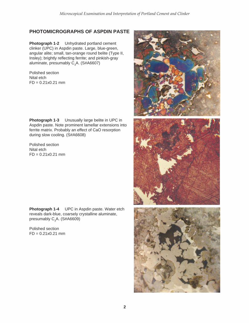
PHOTOMICROGRAPHS OF ASPDIN PASTE
Photograph 1-2 Unhydrated portland cementclinker (UPC) in Aspdin paste. Large, blue-green,angular alite; small, tan-orange round belite (Type II,Insley); brightly reflecting ferrite; and pinkish-grayaluminate, presumably C
3A. (S#A6607)
Polished sectionNital etchFD = 0.21x0.21 mm
Photograph 1-3 Unusually large belite in UPC inAspdin paste. Note prominent lamellar extensions intoferrite matrix. Probably an effect of CaO resorptionduring slow cooling. (S#A6608)
Polished sectionNital etchFD = 0.21x0.21 mm
Photograph 1-4 UPC in Aspdin paste. Water etchreveals dark-blue, coarsely crystalline aluminate,presumably C
3A. (S#A6609)
Polished sectionFD = 0.21x0.21 mm
3
PCA SP030
particles. Although the UPCs are far from identical tothose of modern production, they clearly contain,among other phases, the four principal phases typicalof portland cement (alite, belite, aluminate, and fer-rite). Glassy particles were also observed in the Aspdinpaste and appear similar to those described by Idornand Thaulow (1983), who described some of the mi-croscopic characteristics of a precast concrete wallplaced in front of Portland Hall, Gravesend, Kent,England, in 1847. The wall is said to have been built forWilliam Aspdin. Further discussion of this wall andthe nature of the UPCs is given by Blezard (1981 and1984), who shows photomicrographs suggesting acoarsely crystalline clinker that was slowly heatedand slowly cooled. Cements similar to this Aspdincement may have comprised some of the samplesstudied by LeChatelier and other early workers inclinker microscopy.
Scrivener (1988) studied the Aspdin paste withbackscattered electron imaging (BSE), showing clearlythe development of hydration products pseudomor-phic after the original clinker crystals and drawingattention to the occurrence of layers of hydrationproduct (“inner product”).
In 1897 Törnebohm, a Swedish investigator, pos-sibly realizing that because of compositional variationmineral names might be better suited for clinker phasesthan chemical formulas, clearly described the opticalfeatures of the principal clinker phases in thin sectionsand powder mounts and coined the terms alite, belite,celite, felite, and also glassy residue. Törnebohm statedthat “belite” has two or three sets of cross striations and“felite” has one set of parallel striations formed at lowtemperature. Törnebohm related microscopical datato burning conditions, stating:
1. Well-burned clinkers are less porous and con-tain better-crystallized colorless alite and dirty-green to muddy belite.
2. Brownish-orange celite functions as a flux, pro-moting the development of the silicates.
3. Underburned clinker disintegrates because ofatmospheric moisture combining with residuallime.
Törnebohm also made notable contributions tothe microscopical understanding of cement hydra-tion, a topic that must be left for future discussion.
Richardson (1903-1905) summarized theories onthe chemistry of portland cement and demonstratedthe use of a polarized-light microscope in the predic-tion of cement quality from clinker examinations.Richardson stated: “If the structure is coarser and theelements are more segregated, the cement from such
a clinker will be less reliable.” Most of Richardson’swork, however, was in the laboratory where, withnumerous sintering experiments, he made frequentuse of powder mounts and thin sections to study theproducts. Richardson, undoubtedly, developed anextensive and systematic body of knowledge thatformed foundation for later work by others.
Bates in 1912, describing some of the cementchemistry work at the National Bureau of Standards,stated (p. 369) “It was recognized from the first, that inorder that the studies, which were to be made, mightbe complete, a petrographer with a complete outfit forpetrographic studies must be installed. All burns wouldthen be examined for their constitution according tothe most approved and exacting methods.”
Rankin and Wright (1915), although they werenot particularly concerned with the interpretation ofburning conditions, firmly established the optical prop-erties of pure compounds and the principal phases incommercial cements. These authors systematicallyinvestigated approximately 1000 combinations of lime,alumina, and silica with fully 7000 heat treatmentsand microscopical examinations.
Using Törnebohm’s classification, Guttmann andGille in 1928 tabulated the basic optical properties ofclinker phases and the common hydration products.In 1931, Guttmann and Gille summarized the 50-yearcontroversy over the nature of alite and demonstratedconclusively that alite is C3S. *
According to Insley (1936), polished section ex-amination of portland cement clinker was reported byStern (1908) and by Wetzel (1913); but, largely due topoor technique, the metallographic method was aban-doned until Tavasci’s very detailed paper in 1934 inwhich reflected-light microscopy was combined withthat from transmitted light.
Tavasci (1934) believed that clinker was com-posed primarily of alite, belite (alpha and beta),and celite (a fine mixture of 3CaO•Al2O3 and4CaO•Al2O3•Fe2O3), with free lime as a frequent addi-tional phase. With a series of etches, including nital,oxalic acid, hydrofluoric acid, water, and others,Tavasci carefully described the various effects of thesesolutions on clinker phases and other synthetic com-pounds. Tavasci presented rather meticulous descrip-tions of the forms of belite, suggesting a martensite-type separation in the transformation of alpha to beta.
Tavasci classified belite into three morphologicaltypes: I, II, and III. Belite I was said to show striations,sometimes like twinning, prevalently in two direc-tions. The striae were described as being relatively
* An abbreviated chemical symbolism in which C = CaO, S =SiO2, A = Al2O3, F = Fe2O3, K = K2O, and N = Na2O.

4
Microscopical Examination and Interpretation of Portland Cement and Clinker
thick but not very “fitte” (a term believed by the presentwriter to mean “etching resistance”). Upon etching withalcoholic nitric acid (nital) the striae were hollowed outwith respect to the rest of the grain. Belite II crystalswere generally large, containing very “fitte” striae, thedark striae showing relatively less attack by alcoholicnitric acid than the bright striae. Belite III was compara-tively small and appeared to be an external zone over acore formed by belite I or II. Coarse striation did notoccur in belite III, but fine parallel striations were ob-served like those in belite II. Belite III was said to contain“a kind of veining formed by inclusions which at highmagnification appear white and in strong relief.”
In 1936 Insley (about whom much more is saidlater) clearly showed that (1) alite is tricalcium silicate(C3S), (2) two different habits of dicalcium silicate (C2S)comprise belite and felite, and (3) celite is tetracalciumaluminoferrite (C4AF). Insley’s descriptions and illus-trations of clinker phases remain the basis for much ofsucceeding publications by others.
Among the many historically important contribu-tors to the microscopy of portland cement clinker, LeviS. Brown deserves special recognition for his observa-tional skills and interpretive acumen. Brown workedfor Lone Star Research Laboratory in Hudson, NewYork, in the 1930s and in 1940 joined the research staffat the Portland Cement Association, where he spentapproximately 25 years in cement and concrete inves-tigations. Most of his scientific efforts were dedicated tothe microscopical interpretation of clinker burning,cement hydration, and concrete deterioration. An un-published report (Brown, 1936) contains the followinginteresting observations:
1. C3A and C3S were discriminated in thin sectionsand powders mounted in Hyrax, * a synthetic resinwith index of refraction ** of approximately 1.710.
2. Differences in optical properties of C3S were de-fined and birefringence and morphology wereobserved to show wide ranges; crystal zoningwas not clearly understood.
3. Optical characteristics of C2S, particularly thediscrimination between polymorphic varieties(alpha, beta, and gamma), were described. The“better burned” clinkers were said to containrelatively clear crystals.
4. Optical characteristics of C4AF, especially thecolor variations, were related to burning condi-tions, magnesium oxide content, and a reducingenvironment, the latter indicated by a honey-brown C4AF color and weak pleochroism. Thedarkening and strong pleochroism of C4AF werecorrectly thought to be due to incorporation ofmagnesium oxide.
5. The morphologic and volumetric changes in thetransformation of calcite to lime in a portlandcement raw mix were described.
6. Large crystals of periclase were described andexplained as an effect of annealing of commer-cial clinkers.
7. Gehlenite, found sparingly in practically all port-land cement clinkers, was detected by examina-tion of floating particles that have a uniaxialcharacter and perfect basal cleavage in an oil ofapproximately 1.71 refractive index. Gehlenitewas said to be suggestive of underburning.
8. Sulfate minerals in clinkers, observed as floatingparticles in refractive index oil, were said tooccur abundantly in underburned clinker. Opti-cal characteristics of clinker sulfates comparedwith sulfate phases formed in the laboratory ledto the conclusion that the low-index mineral inclinker is an alkali sulfate with a variable butsmall amount of calcium sulfate held in solidsolution.
9. Free lime was seen to increase with raw feedparticle size and decrease with increasing burn-ing time (flame length).
Brown and Swayze in 1938 published a paperdescribing the application of the microscope to auto-clave problems, namely, free lime and magnesia inportland cement. Three forms of free lime were de-fined: (a) light-burned (quicklime), (b) hard-burned,and (c) air-slaked. The latter type was described as a“heretofore unidentified form of calcium hydroxide”having optical properties different from normal cal-cium hydroxide (portlandite) and thought to be the“Epezit” which was defined by Guttmann and Gille in1928a and 1928b. Epezite was said to differ fromportlandite in optical sign and refractive indices asfollows:
Epezite PortlanditeUniaxial (+) Uniaxial (-)Epsilon = 1.55 - 1.56 Epsilon = 1.545Omega = 1.54 - 1.55 Omega = 1.574
Epezite typically forms tiny popcornlike crystals.Portlandite crystallizes in pore spaces as tablets andplatelets. The growth of epezite was thought to beresponsible for clinker disintegration in open storage(even in supposedly tightly sealed containers on the
* Hyrax (no longer available) is briefly described in Chapter 4under the heading “Techniques with Hyrax.”
** Unless otherwise stated, the indices of refraction given in thisbook refer to sodium light.

5
PCA SP030
laboratory shelf) due to the 97% volume change whenfree lime combines with atmospheric moisture, hencethe term air-slaked.
Brown’s most widely known published work ishis Microscopical Study of Clinkers (1948) in which 21different lots of clinkers were microscopically studiedat the Portland Cement Association laboratories inorder to correlate mineral composition with whatBrown termed the “degrees” of burning in the cementkiln and concrete durability. Although Brown’s de-scription and interpretation of what he termed the“glass” and “dark prismatic” phase may be question-able in the light of recent research, his work in clinkerand concrete microscopy was seminal. Brown contrib-uted significantly to the discussion of clinker phases ina book by Insley and Fréchette (1955).
Brown summarized his philosophy of micros-copy in 1959 when he discussed the two primarymodes of specimen examination (transmitted and re-flected light); the phase rule in relation to the micro-scope; the nature of cement hydration and its effectson strength, water-cement ratio, dimensional stabil-ity, durability, and other concrete properties.
Tavasci (1978) elaborated on the three forms ofbelite (I, II, III), relating them to C2S polymorphs(alpha, alpha prime, beta, and gamma), and attemptedto show the analogy with the austenite-martensiteconversion in high-carbon, hardened steel. Belite Iwas said to contain alpha lamellae (etching relativelylight colored in nital) and alpha prime lamellae (nar-row and etching dark in nital). Belite II was said tocontain alpha and beta; the alpha prime, having origi-nally formed from alpha, was transformed to betaupon further cooling. Alpha remained as an includedphase. Belite III differed from belite II in having sharperand less-regular separation of the alpha inclusions.
Also among the many major historical contribu-tions in clinker microscopy are the works of Parkerand Nurse (1939); Taylor (1943); Gille (1955); Krämer(1960); Nurse, Midgley, and Welch (1961); Midgley(1964); Butt and Timashev (1974); and others. Most ofthese authors are mentioned again in Chapter 7,“Microscopical Interpretation of Clinkers.”
Three publications of European origin are consid-ered required reading for cement microscopists:1. Mikroskopie des Zementklinkers, Bilderatlas, F. Gille,
I. Dreizler, K. Grade, H. Krämer, and E. Woermann(1965, Verein Deutscher Zementwerke),
2. Microstructure of Portland Cement Clinker,Friedrich Hofmänner (1973, Holderbank), and
3. Microscopy of Cement Raw Mix and Clinker, ErlingFundal (1980, F.L. Smidth).As will be evident, the present writer has drawn
heavily on the above three publications, plus severalJapanese reports, particularly the work of Yoshio Ono(1995), whose detailed studies demonstrate the prac-ticality of transmitted-light microscopy in the cementplant. Ono’s Method is discussed in Chapter 6.
A commendable effort to bring cement and con-crete microscopists together for the purposes of shar-ing knowledge and promoting the use of the micro-scope in the construction industry is seen in the found-ing of the International Cement Microscopy Associa-tion (ICMA) in 1980. * Published proceedings of theirannual meetings have helped immeasurably in spread-ing knowledge of various microscopical methods andhave generally stimulated growth in cement qualitycontrol through microscopy in North America.
Illustrating quality-control methods in well ce-ments, polarized-light microscopy and fluorescentmicroscopy have been applied to the analysis of oil-well cement blends containing pozzolans, bentonite,potassium chloride, friction reducer, modified poz-zolan, fluid-loss addition, silica flour, and other mate-rials (Reeves, Bailey, and Caveny, 1983). Examinationof cement polished sections has shown a relationshipof oil-well cement thickening times and retardationrates (Caveny, Weigand, and Bailey, 1983). Cavenyand Weigand (1985) described a good oil-well cementas having well-formed alite (40 to 50 microns), nosurficial deterioration of silicates, low free lime (lessthan 0.5%), and being free of metallic iron.
Relatively recent contributions to oil-well cementmicroscopy include Polkowski (1987) who concludedthat four cements with less than ideal microscopicalcharacteristics still performed acceptably with differ-ent loadings of admixtures.
Carruthers, Livesay, and Wells (1994) describesome of the burning conditions required for produc-tion of a Class H (HSR) oil-well cement: (1) hot burn-ing zone and long retention time (dendritic belite), (2)high burning zone temperature and long burningzone (cannibalistic alite, wrap-around belite), (3)lengthening of burning zone and increasing tempera-ture (belite beginning to disperse, silicate enlarge-ment, and clarification of matrix), (4) dust recircula-tion (zoning in alite), slow cooling from extension ofburning zone farther back in the kiln (ragged belite),and others. Desirable properties of the Class H (HSR)cement include a dead burned clinker with large alite,cannibalistic alite, amoeboidal belite, wrap-aroundbelite, and finely crystalline C3A.
* 1206 Coventry Lane, Duncanville, Texas 75137 U.S.A.e-mail: [email protected] address: www.cemmicro.org

6
Microscopical Examination and Interpretation of Portland Cement and Clinker
The desirable characteristics of Class H well ce-ment were listed by Arbelaez (1990): free lime levelsless than 0.5% with a uniform distribution, C3A lessthan 6.5%, no weathered clinker, using only the 12.7-to 38.1-mm clinker fraction for the cement, relativelyhot burning without production of cannibalistic alite,and avoidance of ragged belite by rapid cooling.
The subject of clinker grindability also has micro-scopical aspects and the most complete literature sur-vey, to date, is that of Hills (1995) who enumerated mostof the prevailing agreed-upon relations (such as de-creasing alite crystal size increasing grindability). Othervariables on which the interpretations were not as clearcut (such as percent liquid phase) were also listed.
Tachihata, Kotani, and Jyo (1981), in a laboratorystudy of the relationships between rate of heating, rawmeal fineness, and other factors, concluded that clin-kers with large crystal sizes in a narrow size rangeshowed unfavorable grindability, and that crackswithin the crystals and at the boundaries were some ofthe most important factors in grindability.
Viggh (1994) studied clinker grindability and otherrelated cement characteristics, concluding, amongother things, that better grindability results with in-crease in liquid and alite percentages, and a decreasein alite crystal size. Poorer grindability resulted whenbelite percentage and crystal size increased. A de-crease in setting time and improvement in strengthdevelopment follow from better grindability.Cement flowage was said to be dependent on theamount of gypsum.
Theisen (1993) described a rapid method of mi-croscopical determination of alite and belite size andapproximation of visible pore space by recording thenumber of intercepts along a line of traverse in succes-sive fields of view. The intercept numbers were usedwith Bogue calculations and related to power con-sumption (kwh/t) in grinding. Data can be gatheredin less than an hour.
Many additional recent publications linking mi-croscopy to a wide range of performance-related prop-erties of cement are given in the following chapters.

7
PCA SP030
CHAPTER 2
Sampling and Sample Storage
ticles, from which a few particles are randomly selectedor riffled (1) for encapsulation in epoxy for reflected-light examination and (2) for further crushing to apowder for immersion in oil on a microscope slide forexamination in transmitted polarized light. Severalencapsulations can be made, thereby increasing theprobability of studying particles representing most ofthe original clinker sizes. One should be aware thatdifferent size fractions of crushed clinkers may havedifferent phase abundances (some alite-rich, othersbelite-rich).
J.D. Dorn (personal communication, 1985) statedthat clinkers less than approximately 25 mm are virtu-ally the same and that larger clinkers exhibit effects ofdifferent cooling rates. Dorn recommended passing aliter of clinker through a crusher, producing particlesof approximately 5-mm diameter, followed by rifflingto a volume of 1/4 liter and pulverizing to less than0.59 mm. The 0.59- to 0.30-mm (No. 30- to 50-mesh)fraction is used for a polished section.
Centurione (1993) recommends an initial 15-kgclinker sample, which is then quartered to 2.5 kg andsieved. The sieved fractions are crushed, sieved into2.4-, 0.6-, and 0.3-mm fractions, and blended. A 50-gram sample is taken for microscopy, XRF, and chemi-cal determination of free lime.
One problem with the crushing of clinker prior toexamination is that microcracks seen in polished-sec-tion or thin-section study are ambiguously interpreted.Microcracks that are not artifacts of sample prepara-tion may, in some investigations, be related to straincaused by thermal stress (Hornain and Regourd, 1980),crystal reorganization, hydration, and expansion.
If the clinker is extremely sandy or dusty, crush-ing prior to sieving may not be necessary. A randomspoonful taken from a well-mixed sample will likelybe adequate.
Other workers prefer to sieve the clinker sample,after which representative portions of arbitrarily
SAMPLING
Taking the clinker sample for microscopical examina-tion has, as yet, no formally accepted procedure andseveral techniques are currently used, largely depen-dent on the purpose of the investigation. Because of timeconstraints during clinker analysis, the clinker samplemust necessarily be small and, therefore, the conclu-sions must be cautiously drawn. A grab sample is pref-erable to composite samples for most investigations.
Hofmänner (1973) recommends the following sam-pling technique:
1. At intervals of five minutes or less take three 2-kgsamples, mix, and quarter down to 500 g.
2. Crush the 500-g sample to 5-mm particles.3. Quarter until a sufficient amount remains for
encapsulation with resin in a 25-mm-diametercup. Two encapsulations are recommended toget a “representative average of the randomsample.”
Ono (1981) recommends a grab sample every eight-hour shift during clinker production; hourly samplesare taken during kiln startup.
Hicks and Dorn (1982) recommend the Ono test(except birefringence) once per day and every time achange is made in the burning process and, once perweek, a polished-section examination of the 0.84- to0.59-mm (No. 20- to 30-mesh) granulated clinker.
For determination of the phase content of clinker,Chromy (1983) utilized polished sections made fromthe quartered residue from 0.5 kg of clinker ground toa particle size passing a 1.0-mm sieve. A 20-mm-diam-eter polished section of particles embedded in epoxywas prepared.
One of the most popular methods involves crush-ing a random clinker sample of roughly a liter volume(1 to 2 kg) to approximately 2- to 4-mm-diameter par-
8
Microscopical Examination and Interpretation of Portland Cement and Clinker
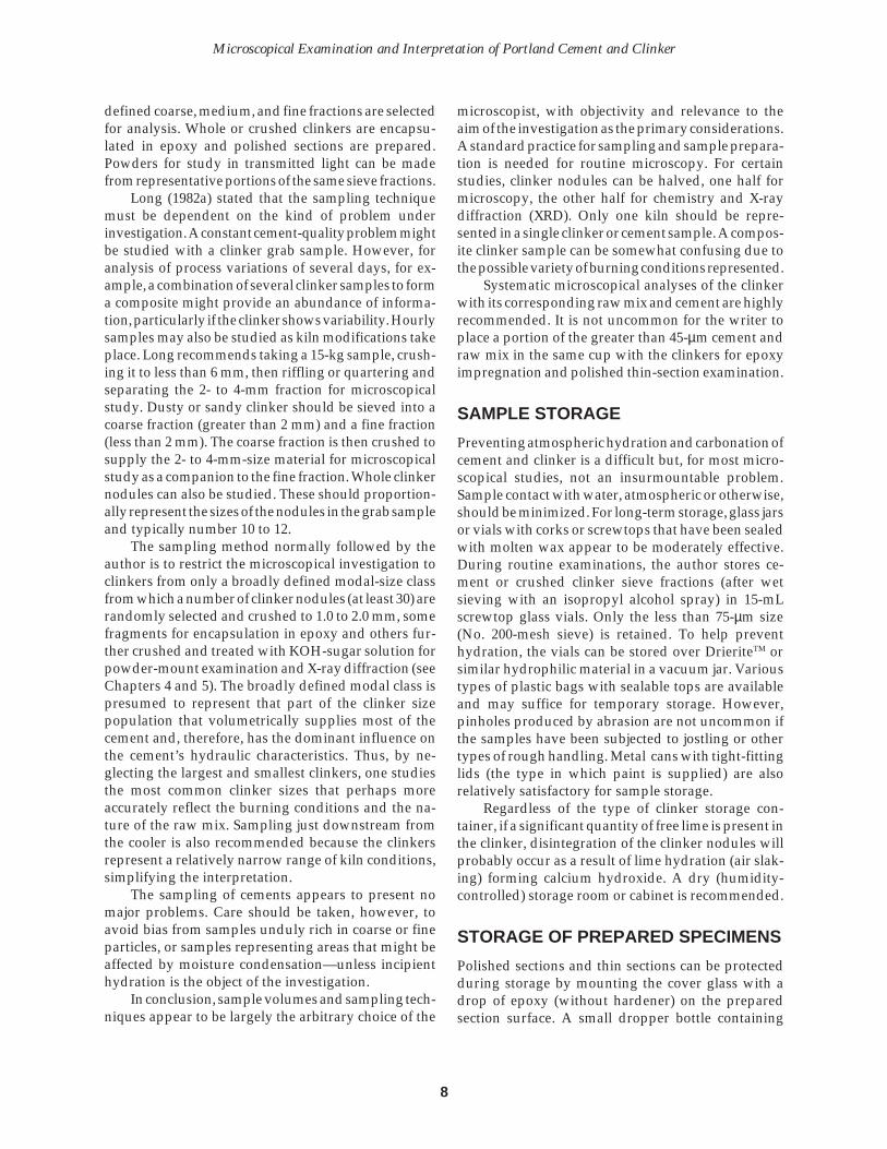
defined coarse, medium, and fine fractions are selectedfor analysis. Whole or crushed clinkers are encapsu-lated in epoxy and polished sections are prepared.Powders for study in transmitted light can be madefrom representative portions of the same sieve fractions.
Long (1982a) stated that the sampling techniquemust be dependent on the kind of problem underinvestigation. A constant cement-quality problem mightbe studied with a clinker grab sample. However, foranalysis of process variations of several days, for ex-ample, a combination of several clinker samples to forma composite might provide an abundance of informa-tion, particularly if the clinker shows variability. Hourlysamples may also be studied as kiln modifications takeplace. Long recommends taking a 15-kg sample, crush-ing it to less than 6 mm, then riffling or quartering andseparating the 2- to 4-mm fraction for microscopicalstudy. Dusty or sandy clinker should be sieved into acoarse fraction (greater than 2 mm) and a fine fraction(less than 2 mm). The coarse fraction is then crushed tosupply the 2- to 4-mm-size material for microscopicalstudy as a companion to the fine fraction. Whole clinkernodules can also be studied. These should proportion-ally represent the sizes of the nodules in the grab sampleand typically number 10 to 12.
The sampling method normally followed by theauthor is to restrict the microscopical investigation toclinkers from only a broadly defined modal-size classfrom which a number of clinker nodules (at least 30) arerandomly selected and crushed to 1.0 to 2.0 mm, somefragments for encapsulation in epoxy and others fur-ther crushed and treated with KOH-sugar solution forpowder-mount examination and X-ray diffraction (seeChapters 4 and 5). The broadly defined modal class ispresumed to represent that part of the clinker sizepopulation that volumetrically supplies most of thecement and, therefore, has the dominant influence onthe cement’s hydraulic characteristics. Thus, by ne-glecting the largest and smallest clinkers, one studiesthe most common clinker sizes that perhaps moreaccurately reflect the burning conditions and the na-ture of the raw mix. Sampling just downstream fromthe cooler is also recommended because the clinkersrepresent a relatively narrow range of kiln conditions,simplifying the interpretation.
The sampling of cements appears to present nomajor problems. Care should be taken, however, toavoid bias from samples unduly rich in coarse or fineparticles, or samples representing areas that might beaffected by moisture condensation—unless incipienthydration is the object of the investigation.
In conclusion, sample volumes and sampling tech-niques appear to be largely the arbitrary choice of the
microscopist, with objectivity and relevance to theaim of the investigation as the primary considerations.A standard practice for sampling and sample prepara-tion is needed for routine microscopy. For certainstudies, clinker nodules can be halved, one half formicroscopy, the other half for chemistry and X-raydiffraction (XRD). Only one kiln should be repre-sented in a single clinker or cement sample. A compos-ite clinker sample can be somewhat confusing due tothe possible variety of burning conditions represented.
Systematic microscopical analyses of the clinkerwith its corresponding raw mix and cement are highlyrecommended. It is not uncommon for the writer toplace a portion of the greater than 45-µm cement andraw mix in the same cup with the clinkers for epoxyimpregnation and polished thin-section examination.
SAMPLE STORAGE
Preventing atmospheric hydration and carbonation ofcement and clinker is a difficult but, for most micro-scopical studies, not an insurmountable problem.Sample contact with water, atmospheric or otherwise,should be minimized. For long-term storage, glass jarsor vials with corks or screwtops that have been sealedwith molten wax appear to be moderately effective.During routine examinations, the author stores ce-ment or crushed clinker sieve fractions (after wetsieving with an isopropyl alcohol spray) in 15-mLscrewtop glass vials. Only the less than 75-µm size(No. 200-mesh sieve) is retained. To help preventhydration, the vials can be stored over DrieriteTM orsimilar hydrophilic material in a vacuum jar. Varioustypes of plastic bags with sealable tops are availableand may suffice for temporary storage. However,pinholes produced by abrasion are not uncommon ifthe samples have been subjected to jostling or othertypes of rough handling. Metal cans with tight-fittinglids (the type in which paint is supplied) are alsorelatively satisfactory for sample storage.
Regardless of the type of clinker storage con-tainer, if a significant quantity of free lime is present inthe clinker, disintegration of the clinker nodules willprobably occur as a result of lime hydration (air slak-ing) forming calcium hydroxide. A dry (humidity-controlled) storage room or cabinet is recommended.
STORAGE OF PREPARED SPECIMENS
Polished sections and thin sections can be protectedduring storage by mounting the cover glass with adrop of epoxy (without hardener) on the preparedsection surface. A small dropper bottle containing

9
PCA SP030
epoxy resin (without hardener) is kept at approxi-mately 40°C on the slide warmer for the purpose ofmounting cover glasses. Keeping the resin at thistemperature in the bottle seems to minimize the crys-tallization that may occur at room temperature. Thecover glass can be easily removed for several months,but even the epoxy (without hardener) will eventuallybond the cover glass to the section. Then the problembecomes one of trying to remove the cover slip with arazor blade or by grinding. The polished surface canbe protected with an acrylic spray, which can beremoved by gentle rubbing with an acetone- or xy-lene-soaked rag. An acrylic spray eventually cracks,however, and does not prevent hydration of free limeexposed on the section surface.
Immersion of epoxy-encapsulated materials inpolished sections in an anhydrous lightweight oil(preferably odorless) in a wide-mouth glass jar with ascrewtop lid effectively minimizes, but does not elimi-nate, hydration. If the specimen is re-examined micro-scopically, the oil appearing on the polished surfacecan be removed with a sonic cleaner containing iso-propyl alcohol, followed by a forceful isopropyl alco-hol spray. Dorn and Adams (1983) used Freon in asonic cleaner to remove residual oil on polished-sec-tion surfaces. In the writer's experience, oil droplets ona polished section can be removed with a brief appli-cation of acetone, followed by an alcohol spray wash,and blow drying.

10
Microscopical Examination and Interpretation of Portland Cement and Clinker

11
PCA SP030
CHAPTER 3
Stains and Etches
unless stated otherwise, the tests are carried out atroom temperature. It will be obvious that the effects ofvarious etches and stains are also functions of timeand clinker phase composition.
Relative reactivities of silicates among severalclinker samples, or comparison of the phase percent-ages of clinkers from different daily productions ordifferent cement companies, can be determined byetching and staining several polished sections simul-taneously at the same temperature. To facilitate thistechnique, one can combine several polished sectionswith a rubber band, immersing the assemblage in theetchant for the required length of time. Thus all sec-tions are exposed simultaneously for the same lengthof time, at the same temperature, and relative rates ofreaction can be evaluated according to the colorsproduced. Similar tests can be performed with 0.2%nital and 0.01% aqueous ammonium chloride. CDTAin successive 15-second applications with examina-tions after each is particularly good to evaluate therelative rates of silicate reactivities in a suite of samplesetched simultaneously. Reaction rates can be increasedby heating the polished section with the hair dryer fora few seconds prior to application of the etchant.
Another helpful procedure in polished sectionexamination is to immerse only one half of the polishedsurface in water, for example, holding the section witha pair of forceps, spray wash the sample with isopropylalcohol, dry, and then rotate the sample 90˚ immersinghalf of the section in nital. Thus the surface is dividedby this procedure into quarters: one quarter with onlywater, one quarter with water plus nital, one quarterwith only nital, and a quarter remaining with no etch.
ALUMINATES AND FREE LIME
A. Potassium hydroxide—ethyl alcohol solution(5%) is placed in contact with the polished sec-
The techniques of imparting color to various crystallinephases preferentially are well known in geology (seeCarver, 1971, and Hutchison, 1974). Stain differentiationbetween plagioclase and potash feldspars and betweenvarious carbonate minerals is commonplace, using par-ticles, thin sections, and polished slabs. Stains and etchesare those liquids or vapors that, when applied to thepolished cross section of a clinker or to a sample ofportland cement, preferentially color or dissolve certainphases observed in reflected or transmitted light. Thecolors mainly result from the refraction, reflection, andinterference of light within the thin layer of reactionproduct formed on the clinker phases. Stains and etchesare used to bring out microstructural details of indi-vidual crystals. Both stains and etches can be related tothe relative reactivities of various clinker phases. Photo-graphs 3-1 through 3-6 illustrate some of the effects of afew stains and etches.
Perhaps the most thorough treatment of the sub-ject of stains and etches is the work of Ellson andWeymouth of Australia (1968). Their paper lists ap-proximately 43 reagent solutions and their effects onportland cement and blast furnace slag phases in termsof (a) reaction type (stain or structural etch), (b) timerequired for the desired effect, (c) recommended tem-peratures, and (d) concentrations. Futing summarizedthe application of many varieties of etches in 1986.
Much of the information given in this chapter wasextracted from the work of John Marlin of the Okla-homa Cement Corporation (now a subsidiary of LoneStar Cement Company, Greenwich, Connecticut).Many of his recipes and results (1978 and 1979) arereproduced in this chapter with only slight modifica-tion but only a few have been tried by the presentwriter. Marlin recommends making fresh solutionsevery two months for most of these stains and etches.Most of the solutions described in the following pageshave simultaneous staining and etching effects, and,

12
Microscopical Examination and Interpretation of Portland Cement and Clinker
tion for no more than 20 seconds. Wash thesection surface in a 1:1 ethyl alcohol-water solu-tion followed by a wash in isopropyl alcohol,and buff for approximately 15 seconds onMicroclothTM *,** wetted with isopropyl alcohol.Wash with isopropyl alcohol. C3A turns blue.
B. Sodium hydroxide—ethyl alcohol solution isprepared with 2.5 g of sodium hydroxide plus 40mL of water plus 10 mL of ethyl alcohol. If thecontact of the polished surface with the solutionis more than roughly 20 seconds, a deposit froma reaction between hydroxide and aluminateforms that buffing will not remove. C3A turnsblue. If determination of alkali sulfates is desired,stain only one time for approximately 10 seconds,washing with 1:1 ethyl alcohol-water solution,followed by isopropyl alcohol. Do not buff. Thistreatment will darken alkali sulfates slightly andwith prolonged treatment (as for C3A) will dis-solve the alkali sulfate, producing a dark void.
C. Potassium hydroxide solution (0.1 molar aque-ous) can be applied in single drop fashion or ina small puddle on a polished surface for 30seconds. Rinse with an isopropyl alcohol sprayand dry with forced warm air. C3A and alkali-aluminate stain blue-brown, alkali sulfate dark-ens, and free lime turns brown.
D. Boiling sodium hydroxide solution (10% bymass) will turn calcium aluminate blue or brownin 20 seconds in a high-alumina cement. Etching30 seconds with a 1% borax solution turns C12A7gray (Long, 1983).
E. Warm distilled water (40°C) in 5 to 10 secondsturns aluminates blue to brown, alite light tan,free lime multicolored, and does not affect belite.
SILICATES
A. Dilute salicylic acid stain is mixed as follows:0.2 g salicylic acid plus 25 mL of ethyl alcoholplus 25 mL of water. After a 20- to 30-secondimmersion, followed by an alcohol spray wash,alite and belite are blue-green. A modification ofthis stain is 0.2 g of salicylic acid plus 25 mL ofisopropyl alcohol plus 25 mL of water, which,after 20 to 30 seconds, reveals that alite stains 50percent faster than belite and which, therefore,can be used to distinguish the two phases. Aprecise immersion time for a series of samplesaids in their comparison.
B. Salicylic acid etchant is made by dissolving 0.5g of salicylic acid in 50 mL of methyl alcohol.After a 45-second etch the alite and belite areclearly seen, the latter showing its lamellar struc-
ture. Longer contact with the solution degradesbelite lamellae. Alite is more strongly etchedthan belite. This etchant can be used prior toammonium nitrate for alite-belite differentia-tion with very little effect on the matrix phases.Reaction of salicylic acid in ethyl alcohol is 50percent that of methyl alcohol and attacks aliteabout twice as fast as belite. With isopropylalcohol, however, the reaction is less than 25percent that of methyl alcohol, and alite is in-tensely and rapidly attacked, with belite almostnonreactive.
C. Nital is perhaps the most common etchant andstain for silicates and improves with age. Nital is1.5 mL of nitric acid (HNO3) in 100 mL of ethyl,methyl, isopropyl, or amyl alcohol. The authorroutinely uses a solution of 1 mL of HNO3 and 99mL of anhydrous isopropyl alcohol. The solu-tion quickly reacts in 6 to 10 seconds with aliteand belite. At a 0.05% dilution the reaction timeis 20 to 40 seconds. Ono (1995) relates alitereactivity to color produced with 0.2% nital.Depending on the relative reactivity of silicates,alite normally turns blue to green, belite is brownto blue—both silicates showing details of inter-nal structure. Nital superimposed on a 20-sec-ond potassium hydroxide etch turns C3A lightbrown and colors the silicates.
D. Acetone-water solution (in a 1:1 proportion)can be used as a rinse because it reacts slowly onsilicates. A 120-second stain time reveals well-stained alite and belite. C3A is also visible.
E. Isopropyl alcohol solution (10%) is an easilymade stain (10 mL of isopropyl alcohol plus 90mL of water) that reacts strongly with alite andweakly with belite in 30 seconds to 2 minutes.C3A exhibits a weak reaction. Compare with HFvapor.
F. Maleic acid attacks alite and belite at aboutequal rates and a little faster than salicylic acid.When followed by NH4NO3, it does not givecolor distinction to alite and belite.
G. Ammonium chloride (saturated, aqueous) col-ors a hexagonal section of alite (perpendicular tothe threefold crystallographic axis) light yellow.The slender hexagonal section of alite (parallelto the c axis) is colored blue. Zoned crystals in theslender hexagonal section show light-blue coresand dark-blue rims. Ono (1995) recommends an
* MicroclothTM is a tough, feltlike, rayon polishing cloth with alow nap marketed by Buehler Ltd., of Lake Bluff, Illinois.
** Manufacturers and products are listed for reference or to assistin locating various products; this does not imply PortlandCement Association endorsement or approval.

13
PCA SP030
aqueous ammonium chloride solution (0.2 to2.0%) for etching of polished sections. He relatedthe thickness of the film produced by etching tothe color of the resulting reflected light with theequation R = 2d(n), where R is retardation, d isthe thickness of the thin film of etching product,and n is approximately 1.5. Thus R = approxi-mately 3d. A table of etch colors is presented inrelation to different values of R and d, using awell-burnt clinker and 0.5% ammonium chlo-ride. Likewise, alite etch colors produced with0.2% HNO3-alcohol are presented in relation tolocation in the clinker, R, and d. Many of Ono’sphotomicrographs, however, indicate etching for20 seconds with water followed by 5 secondswith 2% aqueous ammonium chloride. Uchikawa (1992) summarized the quality-controltechniques for cement and concrete and presenteda numerical etch-color scale from 0 to 16, relatingeach clinker phase reactivity to etch color, using0.01% aqueous ammonium chloride. The interpretedreactivities were said to be relevant to the initial andearly stages of hydration, as well as the sinteringconditions. Alite was reported to be more easilyetched with “the increase in heating rate, the de-crease in burning temperature, the coarsening ofthe particles of raw materials, and the burningatmosphere approaching reducing.” Interstitial mi-crostructure (ferrite and aluminate crystal sizes,and ferrite crystal shape factor) and the etch colorsof alite were correlated with heat of hydration,mortar flow, and setting time. Relatively slowlycooled matrix was hydraulically more reactive butled to lower, more variable, mortar flow and lowerfluidity. The more easily a clinker was etched, theshorter the initial setting time, which was also short-ened by 40 minutes when free lime was increasedby only 0.5%. Slowly cooled belite (Type IIIb varietyshowing extended lamellae and remelting) wasshown to be colorless and, on a color basis, indistin-guishable from quickly quenched belite. Alite withhigh amounts of impurities and high Al2O3/Fe2O3ratio correlated with low 28-day strength. Underreducing conditions, triclinic alite and partial trans-formation of belite to the gamma polymorph wereproduced, along with smaller alite, larger belite,and lower strength development.
Dorn and Adams (1983) have described the vari-ous etch rates of alite and belite in relation tohydraulic activity. A blue color on alite after a 15-second nital etch was said to represent an activealite.
H. Another variety of the ammonium chloride stainis made as follows:
1 g NH4Cl + 20 mL H2O+ 20 mL ethyl alcohol + 10 mL acetone+ 150 mL isopropyl alcohol
Effects of this stain are very similar to those ofNH4NO3 except the NH4Cl stain is approximately25% faster. Alite turns brown in 10 to 20 seconds;belite is unaffected. This stain can be used directlyas a belite indicator by extending the submersiontime to 30 to 45 seconds. Alite turns yellow toyellowish green and belite to brown. The effects ofthis NH4Cl solution are not as clear for belitelamellae as NH4NO3 following salicylic acid.
I. Ammonium nitrate solution is composed of thefollowing ingredients:
1 g NH4NO3 + 20 mL H2O + 20 mL ethyl alcohol+ 10 mL acetone + 150 mL isopropyl alcohol
Alite is colored in 25 to 30 seconds. With increas-ing treatment time, the colors on the silicatesprogressively range from light brown to brownto purplish brown to blue to blue-green to greento yellow-green. Normally, when alite is stainedyellow-green, belite will be brown. This solutioncan be applied following the salicylic acid stain toshow alite and belite with an approximately 30-second submersion time.
J. Hydrofluoric acid (HF) vapor, used to etch andstain a polished clinker, has been a very informa-tive technique (Long, 1982a). Almost all the clin-ker phases can be differentiated with an HF vaporetch. The HF is kept at a temperature of 20°C to22°C. A finely polished surface is held for 5 to 10seconds in HF vapor and, after waiting a minute ortwo for the excess HF fumes to leave the polishedsurface, the section is examined in reflected light.Belite turns blue and alite is brown. With practiceat varying the etch times one can develop reliableHF-vapor etch criteria for other phases such as thealkali sulfates. Prout reported (personal commu-nication, 1984) that a temperature differential be-tween fume and specimen enhances etching. Thespecimen can be cooled or the HF warmed. Inci-dentally, C2AS (melilite) is colored with HF vaporand occurs in high-alumina cement (Long, 1983).NOTE: Care must be taken to avoid damaging themicroscope objective lens with HF vapors ema-nating from a freshly etched polished section.Waiting a few minutes before examination isrecommended. Because of the extreme danger inskin contact with HF, suitable precautions withgloves and ventilated hood are strongly advised.
K. Distilled water was described by Brown (1948)as an etch that enabled one to discriminate nineclinker phases after a relief polish. With the use ofpresent-day materials and equipment, Brown’s
14
Microscopical Examination and Interpretation of Portland Cement and Clinker
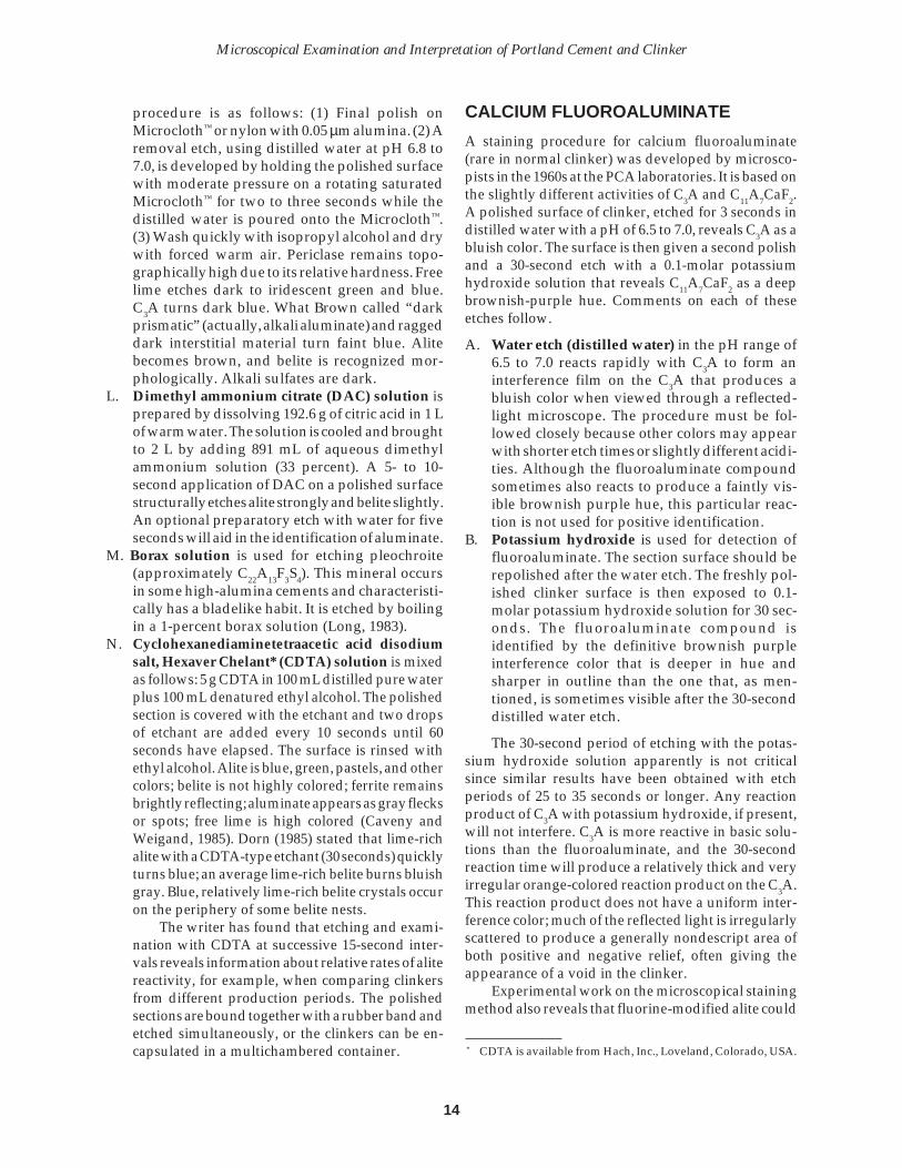
procedure is as follows: (1) Final polish onMicrocloth™ or nylon with 0.05 µm alumina. (2) Aremoval etch, using distilled water at pH 6.8 to7.0, is developed by holding the polished surfacewith moderate pressure on a rotating saturatedMicrocloth™ for two to three seconds while thedistilled water is poured onto the Microcloth™.(3) Wash quickly with isopropyl alcohol and drywith forced warm air. Periclase remains topo-graphically high due to its relative hardness. Freelime etches dark to iridescent green and blue.C3A turns dark blue. What Brown called “darkprismatic” (actually, alkali aluminate) and raggeddark interstitial material turn faint blue. Alitebecomes brown, and belite is recognized mor-phologically. Alkali sulfates are dark.
L. Dimethyl ammonium citrate (DAC) solution isprepared by dissolving 192.6 g of citric acid in 1 Lof warm water. The solution is cooled and broughtto 2 L by adding 891 mL of aqueous dimethylammonium solution (33 percent). A 5- to 10-second application of DAC on a polished surfacestructurally etches alite strongly and belite slightly.An optional preparatory etch with water for fiveseconds will aid in the identification of aluminate.
M. Borax solution is used for etching pleochroite(approximately C22A13F3S4). This mineral occursin some high-alumina cements and characteristi-cally has a bladelike habit. It is etched by boilingin a 1-percent borax solution (Long, 1983).
N. Cyclohexanediaminetetraacetic acid disodiumsalt, Hexaver Chelant* (CDTA) solution is mixedas follows: 5 g CDTA in 100 mL distilled pure waterplus 100 mL denatured ethyl alcohol. The polishedsection is covered with the etchant and two dropsof etchant are added every 10 seconds until 60seconds have elapsed. The surface is rinsed withethyl alcohol. Alite is blue, green, pastels, and othercolors; belite is not highly colored; ferrite remainsbrightly reflecting; aluminate appears as gray flecksor spots; free lime is high colored (Caveny andWeigand, 1985). Dorn (1985) stated that lime-richalite with a CDTA-type etchant (30 seconds) quicklyturns blue; an average lime-rich belite burns bluishgray. Blue, relatively lime-rich belite crystals occuron the periphery of some belite nests.
The writer has found that etching and exami-nation with CDTA at successive 15-second inter-vals reveals information about relative rates of alitereactivity, for example, when comparing clinkersfrom different production periods. The polishedsections are bound together with a rubber band andetched simultaneously, or the clinkers can be en-capsulated in a multichambered container.
CALCIUM FLUOROALUMINATE
A staining procedure for calcium fluoroaluminate(rare in normal clinker) was developed by microsco-pists in the 1960s at the PCA laboratories. It is based onthe slightly different activities of C3A and C11A7CaF2.A polished surface of clinker, etched for 3 seconds indistilled water with a pH of 6.5 to 7.0, reveals C3A as abluish color. The surface is then given a second polishand a 30-second etch with a 0.1-molar potassiumhydroxide solution that reveals C11A7CaF2 as a deepbrownish-purple hue. Comments on each of theseetches follow.
A. Water etch (distilled water) in the pH range of6.5 to 7.0 reacts rapidly with C3A to form aninterference film on the C3A that produces abluish color when viewed through a reflected-light microscope. The procedure must be fol-lowed closely because other colors may appearwith shorter etch times or slightly different acidi-ties. Although the fluoroaluminate compoundsometimes also reacts to produce a faintly vis-ible brownish purple hue, this particular reac-tion is not used for positive identification.
B. Potassium hydroxide is used for detection offluoroaluminate. The section surface should berepolished after the water etch. The freshly pol-ished clinker surface is then exposed to 0.1-molar potassium hydroxide solution for 30 sec-onds. The fluoroaluminate compound isidentified by the definitive brownish purpleinterference color that is deeper in hue andsharper in outline than the one that, as men-tioned, is sometimes visible after the 30-seconddistilled water etch.
The 30-second period of etching with the potas-sium hydroxide solution apparently is not criticalsince similar results have been obtained with etchperiods of 25 to 35 seconds or longer. Any reactionproduct of C3A with potassium hydroxide, if present,will not interfere. C3A is more reactive in basic solu-tions than the fluoroaluminate, and the 30-secondreaction time will produce a relatively thick and veryirregular orange-colored reaction product on the C3A.This reaction product does not have a uniform inter-ference color; much of the reflected light is irregularlyscattered to produce a generally nondescript area ofboth positive and negative relief, often giving theappearance of a void in the clinker.
Experimental work on the microscopical stainingmethod also reveals that fluorine-modified alite could
* CDTA is available from Hach, Inc., Loveland, Colorado, USA.

15
PCA SP030
be identified with the 30-second potassium hydroxideetch. In that case, the characteristic pseudohexagonaloutlines of individual alite crystals would becomeragged and indefinite and the crystals would assumea faint brownish purple hue similar to that seen on theternary compound after the 30-second distilled-wateretch. In all cases thus far, little or no fluoroaluminatecompound has been seen when the fluorine-modifiedalite was present.
It should be pointed out that the potassium hy-droxide method should be applied to materials repre-senting only the compositional field where the usualportland cement phases and fluoroaluminate can oc-cur, as identification does not rely on unique opticalproperties of the various phases.
EXAMINATION OF STAINED CEMENT
A stain technique proposed by Poole and Thomas(1975) for detecting sulfates in aggregates has beenmodified and found to be quite appropriate for gyp-sum, plaster, and anhydrite in portland cement and, tosome extent, alkali sulfates in clinker. The 6% stainsolution is made from an aqueous mixture of BaCl2and KMnO4 in a 2:1 ratio.
A few milligrams of cement or crushed clinker areimmersed in a puddle of the stain solution in a smallbeaker for 1 minute, after which the mixture is washedwith isopropyl alcohol into a 75-µm (No. 200) sieve,and finally into a watch glass. Excess alcohol in thewatch glass can be drawn off with a paper towel. Theresidue is slowly dried in the watch glass at a tempera-ture of approximately 40°C, under a heat lamp or onthe slide warmer, and examined with oblique or trans-mitted light on the stage of a polarized-light micro-scope. Oblique light illuminates the particles from apoint beside the microscope objective. Sulfate miner-als retain a prominent pink to red color. A white paperbackground accentuates the color contrast while view-ing the stained particles with oblique lighting. Refrac-tive-index oils as mounting media can be used withtransmitted light; however, the alteration of somesulfates during the staining may interfere with therefractive-index determinations.
The following easy method for concentratingsome of the sulfates in cement or crushed clinker formicroscopical examination has been developed.(1) Place a small portion of sample into a watch glassand flood with isopropyl alcohol. Swirl the mixture inthe watch glass for a few seconds to concentrate thewhite-to-clear sulfate particles in the center. (2) Drawthe liquid off with a paper towel and dry the remain-ing powder in the watch glass under a heat lamp or onthe slide warmer (no hotter than 40°C). (3) Using a thinmetal spatula, scrape off the top-central area of theresidue in the watch glass and place it on a microscopeslide for examination in oil with a selected index ofrefraction (n).
Although the mount is impure (contains severalphases), in an oil with a refractive index of 1.54,gypsum (n = 1.52 to 1.53) and plaster (n = 1.55 to 1.57)can be distinguished. Gypsum has inclined extinction,but the extinction of plaster is straight (Lea, 1970).Anhydrite (n = 1.57 to 1.61) also shows straight extinc-tion, cleavages at right angles, and relatively highbirefringence. Extinction angles to differentiate gyp-sum from plaster, however, are difficult to apply dueto the very finely microcrystalline structure commonin gypsum and plaster particles. This microstructureappears to be a product of recrystallization due torelatively high temperature, grinding stress, or both,which convert the previously continuous atomic struc-ture into a myriad of minute polygonal crystallineunits. Dorn (personal communication, 1985) reportedthat sulfates such as gypsum and plaster float inrefractive-index oil (n = 1.71) and can be skimmedaside for study in a powder mount; anhydrite maysink in the liquid. A simple heavy liquid-centrifugemethod appears to be an efficient technique for sepa-ration of cement sulfates for microscopical examina-tions and x-ray diffraction, leading, perhaps, to aquantitative determination of phase abundance.
Gypsum, plaster, alkali sulfates, and epezite floatin refractive index liquid (n=1.715) and accumulatejust beneath the cover glass.
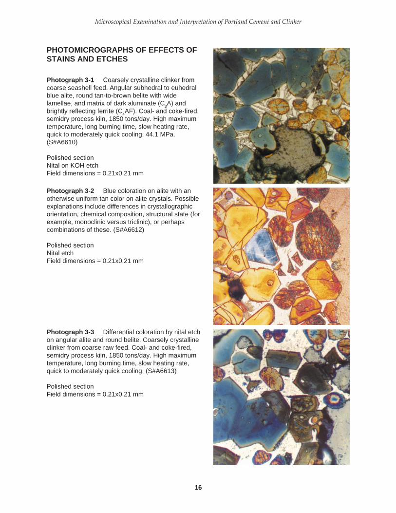
16
Microscopical Examination and Interpretation of Portland Cement and Clinker
PHOTOMICROGRAPHS OF EFFECTS OFSTAINS AND ETCHES
Photograph 3-1 Coarsely crystalline clinker fromcoarse seashell feed. Angular subhedral to euhedralblue alite, round tan-to-brown belite with widelamellae, and matrix of dark aluminate (C
3A) and
brightly reflecting ferrite (C4AF). Coal- and coke-fired,
semidry process kiln, 1850 tons/day. High maximumtemperature, long burning time, slow heating rate,quick to moderately quick cooling, 44.1 MPa.(S#A6610)
Polished sectionNital on KOH etchField dimensions = 0.21x0.21 mm
Photograph 3-2 Blue coloration on alite with anotherwise uniform tan color on alite crystals. Possibleexplanations include differences in crystallographicorientation, chemical composition, structural state (forexample, monoclinic versus triclinic), or perhapscombinations of these. (S#A6612)
Polished sectionNital etchField dimensions = 0.21x0.21 mm
Photograph 3-3 Differential coloration by nital etchon angular alite and round belite. Coarsely crystallineclinker from coarse raw feed. Coal- and coke-fired,semidry process kiln, 1850 tons/day. High maximumtemperature, long burning time, slow heating rate,quick to moderately quick cooling. (S#A6613)
Polished sectionField dimensions = 0.21x0.21 mm

17
PCA SP030
PHOTOMICROGRAPHS OF EFFECTS OFSTAINS AND ETCHES (CONTINUED)
Photograph 3-4 Aqueous NH4Cl etch (30 to 40
seconds). Sections perpendicular to the ccrystallographic (three-fold axis) of alite are brown.Sections parallel to c are blue. (S#A6614)
Polished sectionField dimensions = 0.12x0.12 mm
Photograph 3-5 Large, round, slightly raggedbelite; blue subhedral to anhedral alite; and matrix ofaluminate (C
3A, arrow) and ferrite. Superimposed nital
over KOH produces increased clarity in matrix phasedefinition. (S#A6615)
Polished sectionReflected light with stopField dimensions = 0.21x0.21 mm
Photograph 3-6 Well-differentiated, finelymicrocrystalline matrix of aluminate (C
3A) and ferrite
(C4AF) in nital-etched polished section. (S#A6611)
Oil immersionReflected lightField dimensions = 0.10x0.10 mm

18
Microscopical Examination and Interpretation of Portland Cement and Clinker

19
PCA SP030
CHAPTER 4
Preparation of Polished Sections,Thin Sections, and Particle Mounts
Table 4-1. Recommended Methods of Microscopical Examination
THIN SECTION POLISHED SECTION POWDER MOUNTSTransmitted Light Reflected Light Transmitted Light
Clinker and Cement
Porosity ++ ++ oAlkali Sulfate o ++ oPericlase o ++ oFree Lime o ++ ++(epezite)*Tricalcium Aluminate o ++ oAlkali Aluminate + ++ +Ferrite + ++ +Alite ++ ++ ++*Belite ++ ++ ++*Metallic Iron + ++ ++(magnetic)Calcium Sulfates + ++Portlandite ++ ++ ++
Raw Feed** ++ o +
Quarry Rocks** ++ o +
Pozzolans ++ ++ ++
o Not recommended.+ Recommended, but somewhat difficult, requires more training.++ Recommended, relatively easy.Note: A well-made polished, ultra-thin section, allowing the combination of transmitted- and reflected-light observations, sometimes
simultaneously, is probably the best method for all phases, particularly for fly ash, quarry rocks, and clinkers.
* KOH-sugar treated sample** Optional staining for mineral identifications
trates the principal types of sample preparations.Table 4-1 gives the recommended techniques for vari-ous kinds of materials to be examined. This chaptersummarizes sample preparation procedures for clinkerand cement studies using the so-called “petrographic”microscope with transmitted polarized light, the so-called “metallographic” microscope with reflected light,and the scanning electron microscope (SEM).
Methods of sample preparation for the microscopicalinvestigation of clinker and cement are essentially theclassic geologic techniques of optical mineralogy andpetrography, with minor variations. In this chapterthe use of diamond-rimmed cutoff saws and variousgrinding and polishing equipment is given principalemphasis in the production of polished sections, thinsections, and polished thin sections. Figure 4-1 illus-
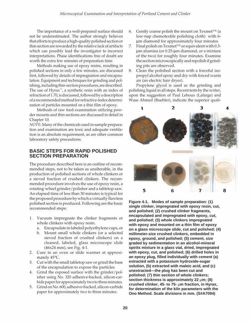
20
Microscopical Examination and Interpretation of Portland Cement and Clinker
The importance of a well-prepared surface shouldnot be underestimated. The author strongly believesthat efforts to produce a high-quality polished section orthin section are rewarded by the relative lack of artifactswhich can possibly lead the investigator to incorrectinterpretations. Phase identifications free of doubt areworth the extra few minutes of preparation time.
Methods making use of epoxy resins, resulting inpolished sections in only a few minutes, are discussedfirst, followed by details of impregnation and encapsu-lation. Equipment and techniques for grinding and pol-ishing, including thin-section procedures, are described.The use of Hyrax™, a synthetic resin with an index ofrefraction of 1.70, is discussed, followed by a descriptionof a recommended method for refractive-index determi-nation of particles mounted on a thin film of epoxy.
Methods of raw feed examination utilizing pow-der mounts and thin sections are discussed in detail inChapter 10.NOTE: Many of the chemicals used in sample prepara-tion and examination are toxic and adequate ventila-tion is an absolute requirement, as are other commonlaboratory safety precautions.
BASIC STEPS FOR RAPID POLISHEDSECTION PREPARATION
The procedure described here is an outline of recom-mended steps, not to be taken as unalterable, in theproduction of polished sections of whole clinkers ora sieved fraction of crushed clinkers. The recom-mended procedure involves the use of epoxy resin, arotating-wheel grinder/polisher and a tabletop saw.An elapsed time of less than 30 minutes is typical forthe proposed procedure by which a virtually flawlesspolished section is produced. Following are the basicrecommended steps:
1. Vacuum impregnate the clinker fragments orwhole clinkers with epoxy resin.a. Encapsulate in labeled polyethylene cups, orb. Mount small whole clinkers (or a selected
sieved fraction of crushed clinkers) on acleaned, labeled, glass microscope slide(46x24 mm), see Fig. 4-1.
2. Cure in an oven or slide warmer at approxi-mately 45°C.
3. Cut with the small tabletop saw or grind the baseof the encapsulation to expose the particles.
4. Grind the exposed surface with the grinder/pol-isher using No. 320 adhesive-backed, silicon-car-bide paper for approximately two to three minutes.
5. Grind on No. 600, adhesive-backed, silicon-carbidepaper for approximately two to three minutes.
6. Gently coarse polish the mount on Texmet™ (alow-nap chemotextile polishing cloth) with 6-µm diamond for approximately four minutes.
7. Final polish on Texmet™ or equivalent with 0.3-µm alumina (or 0.25-µm diamond, or a mixtureof the two) for roughly four minutes. Examinethe section microscopically and repolish if grind-ing pits are observed.
8. Clean the polished section with a forceful iso-propyl alcohol spray and dry with forced warmair (an electric hair dryer).Propylene glycol is used as the grinding and
polishing liquid in all steps. Recent tests by the writer,upon the suggestion of Paul Lehoux (Lafarge) andWase Ahmed (Buehler), indicate the superior quali-
Figure 4-1. Modes of sample preparation: (1)single clinker, impregnated with epoxy resin, cut,and polished; (2) crushed clinker fragments,encapsulated and impregnated with epoxy, cut,and polished; (3) whole clinkers impregnatedwith epoxy and mounted on a thin film of epoxyon a glass microscope slide, cut and polished; (4)millimeter-size crushed clinkers, embedded inepoxy, ground, and polished; (5) cement, sizegraded by sedimentation in an alcohol-mineralspirits mixture in a glass vial, dried, impregnatedwith epoxy, cut, and polished; (6) drilled holes inan epoxy plug, filled individually with cement (a)extracted with a potassium hydroxide-sugarsolution, (b) extracted with maleic acid, and (c)unextracted—the plug has been cut andpolished; (7) thin section of whole clinkers;section thickness is approximately 22 µm; (8)crushed clinker, 45- to 75- µm fraction, in Hyrax,for determination of the kiln parameters with theOno Method. Scale divisions in mm. (S#A7094)

21
PCA SP030
ties of food-grade mineral oil, the type used in “babyoil,” as an excellent, low-viscosity, non-toxic liquid fora grinding vehicle and saw-blade coolant. Slight reac-tion of “baby oil” and mineral oil with the silicatesprecludes its use in polishing, unless the reaction(etching) is seen to be helpful. Recent results with a“hydraulic line “ oil, apparently a food-grade mineraloil designated as “Mobil DTE® FM 32,” are quitepromising. This oil can economically substitute forpropylene glycol and other liquids in sawing andgrinding (but not polishing).
Pressure on the section surface during grinding isone kilogram. Excessive pressure causes too muchtopographic relief on the section surface, requiring along time in the polishing step. Care should be takennot to allow drying of the polished surface prior to thelast step because grinding and polishing debris isdifficult to remove, even with a sonic cleaner. Con-tamination of a polishing cloth can quickly ruin apolished section, sometimes requiring the worker toreturn to the grinding steps. Therefore, between eachof the grinding and polishing steps, the section iswashed with isopropyl alcohol.
ENCAPSULATION, IMPREGNATION,AND PARTICLE MOUNTING
Many materials (clinkers, metals, rocks, minerals, andso on) require impregnation or encapsulation or bothin order to prepare them properly for sectioning. Ifthey are friable, or even slightly crumbly, impregna-tion is mandatory to produce a high-quality section.Several resins are suitable for both impregnation andencapsulation (see Table 11-2).
The epoxy-resin procedures described here areintended for single polished sections and polished thinsections of selected sieve fractions of whole or frag-mented clinkers, rocks, bricks, ceramics, concrete, andmany other materials. The desirable properties of anepoxy-encapsulating and -impregnating medium are:
1. Insolubility of the hardened epoxy in acetone,xylene, alcohol, or other similar solvents.
2. Hardness sufficient to promote the develop-ment of a relatively flat surface during grindingand to minimize the development of particlerelief during polishing.
3. Quick setting, within a few hours at most, withneither inordinate heat generation nor excessiveshrinkage. Some epoxies and other cements, suchas cyanoacrylate ester (Super Glue™), whichharden in only a few minutes, are recommendedin circumstances where quick answers areneeded.
4. Low viscosity for maximum penetration of thespecimens. Xylene and toluene can be used as athinner at a concentration of not more than 25percent by mass of resin, but these liquids alsosoften the epoxy and lengthen the curing time.Filling as many of the pores as possible withepoxy is desirable in order to reduce retention ofgrinding and polishing debris and of cleaningliquids that can interfere with stains and etches.Low viscosity resin is a suitable medium forproducing a size-graded cement or raw feedsample, using a centrifuge to effect the particleseparation and segregation in a glass or polysty-rene test tube (Campbell, 1986).
5. Wetting characteristics that produce a tight bondon the particles, improving edge retention of theparticles during grinding and polishing.
Encapsulation and Impregnation
The procedure utilizing epoxy resins to encapsulateand impregnate a wide range of materials in thepetrographic laboratory is as follows:
1. Immerse the whole clinker or a sieved fractionrepresenting several clinkers in the freshly mixedepoxy+hardener in a small, labeled polyethyl-ene cup (approximately 10-mL capacity and 25-mm diameter), or other suitable labeled con-tainer, coated with a thin film of silicone moldrelease. A small file-card label, inscribed withIndia ink, can be placed on the inside of the cupbefore the sample and epoxy are added. If a thinsection is to be made and determination of itsthickness is necessary, quartz grains (50 to 100mesh) with a known constant birefringence of0.009 may be added to the mix in this step. Thin-section thickness can, therefore, be calculated.The inclusion of quartz increases the time re-quired for sawing, grinding, and polishing dueto the mineral’s hardness (7 on Mohs’ scale).
2. Place the polyethylene container with its con-tents in a vacuum container and evacuate for afew minutes. Epoxy will bubble under vacuumand, if the container is too full, will overflow.Periodically breaking the vacuum will reducethe bubbling tendency. Slowly release thevacuum, allowing atmospheric pressure to forcethe resin into the sample.
3. Epoxy hardening time ranges from 10 minutesat 105°C up to several hours at room tempera-ture. Temperatures above 75°C or several hourson the slide warmer cause significant strain bire-fringence in the epoxy, thereby reducing its

22
Microscopical Examination and Interpretation of Portland Cement and Clinker
optical usefulness in transmitted light. Strain isminimized by curing at room temperature. Forpolished sections, epoxy strain is normally notimportant. Waiting time for the epoxy to hardenis almost never a problem because, normally,several clinker projects are concurrently under-way and in various stages of completion.
Prout (letter, 1984) recommends the use ofQuickmount™ (see Table 11-2) which hardens in 25 to30 minutes. Clinkers are placed in bottomless brasscups on a glass plate covered with a petroleum jelly,such as VaselineTM, and the Quickmount is added.
To speed the sample encapsulation/impregna-tion step using a slide warmer or hot plate, the tech-nique described by Chromy (1992a) is helpful. Asample cup, the bottom of which was covered with 1.0to 2.0 mm-diameter clinkers or crushed clinker par-ticles, was heated to approximately 80˚C. Freshly mixedlow-viscosity epoxy resin was poured over the clinkerparticles and allowed to harden, requiring from 5 to 10minutes. The encapsulation was then sawn to exposethe clinker sections or, better, the bottom side wasground with a coarse grit (180 to 320) to quickly exposethe particles.
For encapsulation cups, the present writer hasoccasionally used 20 to 25 mm-tall cylinders madefrom sections of a copper or brass pipe and some of therelatively heat-resistant polyvinylchloride plastics,both reusable. The interiors of these containers arecoated with silicone stopcock grease as a bond breaker.A glass microscope slide, also coated with siliconestopcock grease, supports the cylinder and the pair areplaced on the slide warmer or hot plate; the epoxyresin is introduced as described above.
SAWING, GRINDING, AND POLISHING
The wide variety of available sawing, grinding, andpolishing equipment, and the necessity for economi-cally producing a high-quality polished section, resultin several options in building a compact, relativelymaintenance-free and inexpensive system for samplepreparation.
Isomet™ and Minimet™ Method
Preparation of high-quality polished sections or pol-ished thin sections requires expertise and patience. Atabletop saw (the Isomet™) and a small polishingdevice (the Minimet™) have greatly improved thepolishing of encapsulated clinkers and single thinsections. The method of preparing polished sectionsand polished thin sections described here is relatively
quick and, in the long run, economical, especially ifseveral sections are examined in the course of micro-scopical investigations. Although not as fast as grind-ing and polishing with a horizontal rotary wheel, themajor advantage of the Isomet-Minimet method isthat the instruments are busy cutting, grinding, andpolishing while the microscopist is elsewhere, return-ing frequently to keep the project progressing. Inaddition, the Minimet™ is useful in polished sectionelectron microprobe studies. The Isomet-Minimet pro-cedure is as follows:
1. The sample is impregnated and encapsulatedwith epoxy resin as previously described.
2. The encapsulation is placed in the proper chuckattached to the Isomet™ saw, which slowly cutsthe sample as it is lowered by gravity onto aslowly moving, thin, diamond-rimmed blade.The blade edge passes through propylene glycol(or “baby oil”) in the coolant container. Sawingtime normally takes 5 to 10 minutes, after whichthe saw automatically stops. A 127-mm-diam-eter blade with 45-mm flanges is recommended.
3. At this point, the Minimet™ is used for grindingand polishing. A 4.75-mm-diameter hole isdrilled into the center of the top of the encapsu-lation into which the arm of the Minimet™ isplaced. Prout (letter, 1984) recommends the useof a carbide-tipped bit. The bottom of this holemust be 5.6 to 6.4 mm from the surface to bepolished. A sample alignment fixture (also sup-plied by Buehler Ltd.) aids in drilling the hole tothe standard depth. Using a moderate load ofone half to one kilogram on the encapsulation,the freshly cut surface is ground successivelywith propylene glycol on No. 320 and No. 600,adhesive-backed, silicon-carbide papersmounted on glass platens within plastic bowlsplaced on the Minimet™. A moderate Minimet™arm speed is used. Recent models of theMinimet™ do not require hole-drilling becausethe sample is held in a “caged” holder. Approxi-mately 6 to 10 minutes for grinding each paperis normally sufficient, after which the sample isthoroughly cleaned with isopropyl alcohol in asonic cleaner or with a spray bottle. Using afigure-eight motion, the sample is finely groundby hand on a glass plate with 5-µm alumina inisopropyl alcohol, polishing oil, or propyleneglycol for approximately three minutes. Again,the sample is thoroughly cleaned in alcohol.
4. At the same speed and load settings, an ad-equate polish is produced in approximately 6 to10 minutes as the sample moves in an irregularmanner on the adhesive-backed Texmet™ on

23
PCA SP030
which a few drops of propylene glycol (or pol-ishing oil) and 0.3-µm alumina have been placed.The sample is removed and thoroughly cleanedas previously described. If, after microscopicalinspection, the polished surface still shows grind-ing pits, repeat the polishing step. Diamondpaste can be applied to Texmet™ along with thealumina.
5. The final polish (optional) is produced in ap-proximately 6 to 10 minutes with the Minimet™,using liberal amounts of 0.05-µm alumina onTexmet™ with a few drops of propylene glycolor polishing oil, using the same speed and loadsettings. Care must be taken, if using isopropylalcohol as the vehicle, to prevent drying of thecloth during polishing. For easy recognition ofpericlase, relief is enhanced by using Microcloth™or equivalent and 0.05-µm alumina. Diamondgrinding and polishing compounds quickly pro-duce a superb surface and are advisable espe-cially when use of the microprobe is anticipated.
6. After thoroughly cleaning the specimen first witha sonic device then with an alcohol spray, anddrying with forced warm air, the polished sec-tion can be examined in reflected light. An etchedsurface may be necessary for study with a scan-ning electron microscope and microprobe.
Use of the Horizontal RotaryGrinder/Polisher
The versatility of this instrument is clear from the factthat its rotating wheel is removable and interchange-able with other wheels on which a variety of adhesive-backed grinding papers and polishing cloths can beattached. Consequently, with a single instrument andseveral interchangeable wheels, the entire grindingand polishing process can be accomplished. Or threeinstruments are used with several interchangeablewheels: one for coarse grinding, another for fine grind-ing, and a third (with variable speed) only for polish-ing. Interchangeable wheels on which polishing clothsand polishing compounds have been placed are keptin large zip-lock plastic bags between periods of use inorder to minimize contamination. This is particularlyimportant when diamond is used as the polishingcompound. Having more than one instrument lessensthe chances for contamination by decreasing the han-dling of wheels. A section can be routinely ground,polished, and sonically cleaned in approximately10 minutes.
Assuming that the sample has been impregnatedand encapsulated in epoxy resin as previously de-scribed and that the mount has been cut with the
Isomet™ or other suitable saw, the encapsulation isready for grinding and polishing as follows:
1. Grind the saw-cut surface by hand for at leastthree minutes on a rotating wheel with an adhe-sive-backed, No. 320-grit, silicon-carbide paper.Wheels and discs with embedded diamonds arealso available and highly recommended becausethey significantly shorten the grinding steps. Pro-pylene glycol or polishing oil are used as vehiclesin all grinding and polishing.
While the encapsulation is in contact with thegrinding paper, using a moderate pressure (1 kg)move the mount clockwise (opposite the direc-tion of the revolution of the wheel). Periodicallyrotate the encapsulation between the fingers topromote uniform abrasion. The wheel rotates atapproximately 350 revolutions per minute. Tominimize relief on the section surface, use only amoderate pressure on the wheel during grindingand polishing. Excessive relief is very difficult to“polish out” and it makes the observation ofalkali sulfate troublesome.
2. After cleaning the fresh, coarsely ground surfacewith a forceful isopropyl alcohol spray, apply aNo. 600 grit, silicon-carbide, adhesive-backedpaper to the grinding wheel and grind the speci-men surface for at least three minutes. Be certainto clean the encapsulation and hands thoroughlybetween the grinding steps. Contamination canquickly ruin all previous work and is quite prob-able with a less than careful technique. A forcefulalcohol spray is moderately successful for clean-ing, but a sonic cleaner followed by the isopropylalcohol spray appears best.
3. After thorough cleaning, coarse polish the samplefor at least four minutes on Texmet™ to which 6-µm diamond paste has been applied.
If the clinker is hard and dense, encapsula-tion, impregnation, and sawing are not absolutelynecessary. A flat surface can be produced by ap-plying the clinker to a coarse grinding paper (No.240 grit or coarser) on a rotating wheel, followedby the required grinding and polishing steps.
4. Final polishing of the clinker by hand requiresdiligence, patience, and practice to produce ahigh-quality finish, but it can be done in only afew minutes. The edge of the section surfaceshould be beveled (rounded) by abrading itagainst a fine steel file or a coarse abrasive paperattached to a rotary wheel to remove sharp cor-ners or edges that might tear the polishing cloth.
Using a thick slurry of 0.3-µm alumina onTexmet™ (or equivalent polishing cloth) withpolishing oil or propylene glycol as a vehicle,
24
Microscopical Examination and Interpretation of Portland Cement and Clinker
polish the sample on the rotating horizontal wheel.A moderate pressure on the sample against theTexmet™ with a circular motion opposite to therotation of the wheel facilitates the production ofa mirror finish in approximately three minutes.
5. An additional polishing step (optional) is accom-plished in roughly two minutes with 0.05-µmalumina on Texmet™, followed for one minuteon Microcloth™, which, because of the slight napof the latter, will produce a minor relief and canbe helpful in identifying periclase.
After cleaning the polished surface with isopropylalcohol in the sonic cleaner, the section is dried withforced warm air and is ready for study in reflected light.Effects of stains and etches can be removed by repolish-ing the section with 0.03-µm alumina and Texmet™.Suitably polished and etched surfaces can be examinedwith a scanning electron microscope.
Drafting linen, washed to remove the starch, can besuccessfully used as a polishing cloth with SnO2 or otherpolishing compounds. Diamond pastes or aerosol spraysare applicable in all the grinding and polishing stepsand are highly recommended. In addition, Kraft wrap-ping paper with 0.25-µm diamond paste on the polish-ing wheel produces an excellent low-relief surface, par-ticularly valuable for detection of alkali sulfate.
Preparation of a low-relief polished-section surfacewith Kraft wrapping paper is easily done by “forming”water-saturated paper over the polishing wheel, plac-ing a rubber band around the sides to hold the paper inplace, and allowing the assemblage to dry on the slidewarmer or in a low-temperature (<50˚C) oven. Forapplication on the MinimetTM the paper is formed overthe glass platen in the polishing bowl. If desired, a waterslurry containing diamond or alumina powders can beallowed to dry on the paper, thus facilitating the polish-ing with the diamond paste (0.25 µm) added later.Liquids, such as propylene glycol or polishing oils, arenot used on the papers during polishing.
Resin-bonded diamond discs placed on a flat table-top function quite well for rapid hand grinding of asaw-cut surface of epoxy-encapsulated clinkers prepa-ratory to polishing (Hoodmaker, personal communica-tion, 1985). A few drops of propylene glycol are used asthe grinding and polishing liquid. The diamond discsare cleaned with soap and water.
Harris’s Technique
A quick technique using Duro Super Glue™ (contain-ing a cyanoacrylate ester), or equivalent, has been de-scribed by Roy Harris (1984) of The Monarch CementCompany, Humboldt, Kansas. With Harris’s method
the -0.59-mm to +75-µm mesh clinker fraction is pol-ished on a glass microscope slide, the entire proceduretypically requiring less than 40 minutes. Harris’s tech-nique, designed for rapid analysis, is as follows:
1. On a cleaned, labeled, petrographic glass slidesprinkle a liberal amount of crushed clinker andadd a few drops of Super Glue™, or equivalent.
2. Place the slide on the slide warmer for 5 minutesat 105°C.
3. With a slide holder designed for use with theMinimet™, the mounted material is groundby hand with 5.0-µm alumina on a glass plate.Isopropyl alcohol or polishing oil is used asthe vehicle.
4. After cleaning the slide, slide holder, and hands,the final polish is accomplished with theMinimet™ with 0.3-µm alumina and polishingoil or propylene glycol on Texmet™.
This writer has had excellent results using tech-niques somewhat similar to those of Harris (1984) forproducing polished sections of small whole clinkers(pea size), crushed clinkers (1 to 2 mm), or cements.The technique, using epoxy instead of Super Glue™,is as follows:
1. Place 15 to 20 small clinkers or clinker fragmentsin freshly mixed epoxy resin with hardener andvacuum impregnate.
2. Remove the clinkers from epoxy with forceps andplace them on a clean, labeled, petrographic glassslide.
3. Put the slide in an oven (or on a slide warmer) setat 50°C. The epoxy that flows from the clinkersduring heating is sufficient for bonding the clin-kers to the glass.
4. Withdraw the slide from the oven and allow theslide to cool for a minute or two. If any epoxy hashardened on the bottomside of the glass, scrape itoff with a single-edged razor blade. The slide,with clinkers firmly mounted, is now ready forcutting on the tabletop saw, or grinding, afterwhich full cross sections of the clinkers will beexposed. Cutting time is approximately threeminutes. Grind the saw-cut surface with No. 320and 600 silicon-carbide papers on the rotarygrinder. Using the slide holder, grind the sampleon a glass plate with 5-µm alumina.
5. Polishing the mounted clinkers can be accomplishedin as short a time as three minutes on the rotarypolisher or four to eight minutes with the Minimet™,using 0.3-µm alumina on Texmet™ and isopropylalcohol or propylene glycol. The writer prefers to

25
PCA SP030
use propylene glycol (or polishing oil) with theMinimet™ because evaporation is slow and theMinimet™ can be largely left unattended.
Between polishing steps, the mount and slide holdershould be cleaned with a forceful isopropyl alcoholspray. The hands may be washed with soap and water.Before examination, the polished section should becleaned in a sonic cleaner with isopropyl alcohol, fol-lowed by a brief rinse with an alcohol spray.
Up to 30 samples of cement, embedded in epoxyand polished on the same glass slide (50x75 mm), havebeen simultaneously etched and studied.
THIN SECTIONS
Routine clinker investigations normally do not involvethin sections. However, for some aspects of clinkerresearch and for many raw material studies, thin sec-tions are invaluable.
A clinker thin section can be made from thepolished epoxy encapsulation after the latter has beenstudied in reflected light and mounted on a glassmicroscope slide with epoxy resin. The thin-sectiontop surface may also be polished and, therefore, thesection can be studied with both transmitted andreflected light, each of which has distinct advantages.Thin sections on the order of 15- to 20-µm thick can beeasily made, using a diamond-rimmed cutoff saw,diamond grinding equipment, a glass plate, and pol-ishing wheels. At a thickness of approximately 15 µmthe problem of crystal overlap is minimal. Examina-tion in transmitted light allows measurement of opti-cal properties, such as birefringence, and observationof pleochroism; reflected-light examination at highermagnification (particularly with oil immersion) per-mits study of the interstitial materials and hardnessrelief. Doubtful phase identifications with reflectedlight may be resolved with transmitted light. By usinga multichambered container, selected size fractionsof the clinker, cement, and raw feed can be combinedin a single encapsulation. The procedure for makingthin sections, requiring a worktime of approximately15 to 30 minutes, is as follows:
1. The previously ground (or polished) surface ofthe encapsulation is mounted on a cleaned, la-beled, petrographic slide (standard size, 46x24mm) with a small amount of epoxy. The writerhas found that by smearing and striking off a fewsuccessive droplets of epoxy with the glass mi-croscope slide, the epoxy fills virtually all thevoids on the section surface and thereby pro-motes a firm bond. A weight of approximately
100 grams, such as a lead fishing sinker or a25.4-mm diameter hexagonal steel nut, weighingapproximately 125 grams, can be placed on top ofthe mount during hardening of the epoxy tomaintain a uniform epoxy thickness between thepolished surface and the glass slide. The topsurface of the slide warmer should be protectedfrom epoxy with aluminum foil, waxed paper, or,better, a 4 mil polyethylene sheet. Epoxy thatoverflows the slide and hardens on the bottom ofthe slide must be carefully removed with a single-edged razor blade after hardening. Curing timeat 40-50°C on the slide warmer may range from 2to 5 hours, depending on the type of epoxy. Someepoxies are rapidly cured with ultraviolet lightand work quite well.
2. After the epoxy has hardened, the excess mountis removed by sawing on the tabletop saw or athin-section cutoff saw or similar device (for ex-ample, the Buehler PETRO-THIN™) so that awafer with a thickness of approximately 0.5 mmremains on the glass slide.
3. The wafer is then slowly and gently reduced toapproximately 30 µm on the diamond cup wheelof the oil-cooled thin-section grinder or othersimilar equipment. Grinding time is approxi-mately five minutes. If a mechanical thin-sectiongrinder is not available and time is not a problem,the wafer thickness can be reduced by hand, usinga Buehler thin-section holder (Buehler catalogNo. 30-8005) and a sequence of coarse-to-fine,adhesive-backed, silicon-carbide papers or, pref-erably, diamond discs on a horizontal rotatingwheel. Propylene glycol as the vehicle (“babyoil”) and a speed of approximately 200 to 350revolutions per minute are recommended. Ratherthan using the thin section grinder for the entiregrinding step, less damage to the thin sectionresults when thickness reduction from 30 to 20 µmis accomplished with silicon-carbide papers onthe rotary wheel, or with loose No. 600 grit silicon-carbide powder on a glass plate. Finally, gentlehand grinding with a 5-µm alumina for a fewminutes with alcohol or propylene glycol on aglass plate brings the section to the proper thick-ness, which for portland cement clinker is ap-proximately 15 to 20 µm. Raw feed thin sectionsand “half” sections are described in chapter 10.Half sections can be made by lapping (grinding)the upper parts of particles embedded in epoxyresin on a glass microscope slide. The preparationtechnique is far less time-consuming than that fora normal thin section, the latter requiring a planarcross section of both the upper and lower portions

26
Microscopical Examination and Interpretation of Portland Cement and Clinker
of most of the particles. The half section providesvirtually the same information. After extractionof the clinker matrix phases with a KOH-sugarsolution, for example, alite and belite microstruc-ture can be examined with both transmitted andreflected light (sometimes simultaneously) on agrain-by-grain basis in a polished half section.The use of half sections is particularly well-suitedfor the examination of raw material powders, andtherefore, step-by-step details of the method aregiven at the end of Chapter 10.
4. Using Texmet™ with liberal amounts of 0.3-µmalumina, a few drops of alcohol, propylene glycol,or polishing oil and a slide holder, the thin sectionis polished on the rotating wheel at a mediumspeed and moderate pressure. Circular movementof the slide opposite to the direction of rotation ofthe polishing wheel is recommended. This polish-ing step requires approximately three to five min-utes. Although this step is not intended to reducethickness, with extended application some reduc-tion in thickness does occur. The Minimet™ canalso be used to polish thin sections. With a moder-ate speed and load, using 0.3-µm alumina,Texmet™, and propylene glycol or polishing oil,the Minimet™ can be left largely unattended dur-ing the polishing. Clean the slide thoroughly.
5. An optional final polish is accomplished with 0.05-µm alumina or Microcloth™ in three to five minuteson the rotary wheel. Diamond paste is recommendedfor thin sections that are to be studied with thescanning electron microscope and the microprobe.The section should be an optimum thickness ofapproximately 15 to 20 µm, at which the interfer-ence colors in cross-polarized light are low first-order gray for quartz and alite and first-order whit-ish gray to yellowish white for belite. At thicknessesless than 20 µm, damage to the quartz becomesprogressively more significant. However, signifi-cant clinker damage with these techniques does notoccur in most cases until a thickness of approxi-mately 10 µm is reached. For many crystals thedamage occurs in the form of cleavage cracks whichare sometimes helpful for phase identification.
6. The thin section is then cleaned with isopropylalcohol in a sonic cleaner, followed by a forcefulspray of isopropyl alcohol, then dried with warmair. The section is ready for staining, etching, andexamination in reflected light. For work in trans-mitted light, the cover glass is loose-mounted tem-porarily with refractive-index oil (n = 1.71). Thus,the cover glass can be removed and the slide cleanedwith isopropyl alcohol when necessary to examinethe section again in reflected light. Effects of most
stains and etches can be removed by repolishing thesection with 0.3-µm alumina on Texmet™, but oc-casionally one has to regrind the surface to ensureagainst misinterpretations promoted by superim-posed effects of some etches. Recently developedvibratory polishing devices appear to producetrouble-free, perfectly polished sections with verylittle handling by the technician. Preparation ofmultiple samples simultaneously has been detailedby Ahmed (1991). Also, the use of a steel-mesh pad(Bueler’s Ultra-Plan™) for production of a flat sec-tion surface prior to polishing, and very importantfor good thin sections, is described by Ahmed (1996).New equipment and methods of sample prepara-tion are described by Ahmed (1997).
The writer has found that by extending the time ofthe coarse polishing step with 6-µm diamond onTexmet™ or Ultra-Plan™, an intentionally wedgedsection that thins to zero thickness on one side and isapproximately 20 µm on the other side can be pro-duced. Although subsequent polishing thins the sec-tion somewhat, it usually is not detrimental. A wedgedpolished thin section is actually advantageous for (1)determination of phase birefringence on the thick sideand (2) examination of interstitial microstructure intransmitted light on the relatively thin side.
Ultrathin sections for light microscopy and SEM-EDXA or microprobe work can be made by using anepoxy disc that has been polished on both sides insteadof a glass microscope slide. An epoxy-encapsulatedand polished section of clinker is attached to the discwith epoxy. A wafer is cut, followed by grinding andpolishing to a thickness of approximately 10 µm.
A light application of an acrylic spray protects thethin section during storage and can be removed withxylene, trichlorethylene, or isopropyl alcohol. Prefer-ably, a cover glass is mounted in epoxy resin (withouthardener). The cover glass can be removed by sliding itoff with the fingers until the resin hardens in a fewweeks or months. The residual liquid resin is readilyremoved by a stream of toluene or acetone.
Polished mounts and polished thin sections are pre-pared commercially by several companies (Table 11-3).Waiting time may range from a few days to several weeks.For clinker thin sections, the microscopist must specifythe required thickness and that nonaqueous media mustbe used in cutting, grinding, polishing, and cleaning.
TECHNIQUES WITH HYRAX™AND MELTMOUNTTM
Properly cured Hyrax™ has an index of refraction ofapproximately 1.70, which is very close to most clinker

27
PCA SP030
phases. Therefore, when used as a mounting mediumfor a clinker thin section and its cover glass, or for wholeparticle mounts as in the Ono Method, the high qualityof the preparation becomes a permanent feature,changed only by remelting the resin. Unfortunately,Hyrax™ is no longer available from the referencedsource in the original edition. Meltmount™ 1.70, mar-keted by McCrone and Cargille, may be a suitablesubstitute but has a faint yellow color and tests arerequired; the addresses have been placed in Table 11-2.The procedures for using Hyrax™ or MeltmountTM as apowder-mounting medium are described below.
1. Place a ceramic-covered, iron-wire triangle on asmall, level, electric hotplate under a ventilatinghood. Place separately on two corners of the leveltriangle a cleaned, labeled glass microscope slide(petrographic type, 46x24 mm) and a cleanedcover glass. Bring the temperature of the glassslide and cover glass to approximately 90°C.
2. Place a drop of Hyrax™ (normally shipped di-luted with toluene or xylene) on the petrographicslide and add a few grains of the clinker or cement(44- to 75-µm fraction, for example).
3. Stir the particles briefly with a clean needle to pro-duce a uniform dispersion and allow the mixture toheat until it stops bubbling (evaporation of toluene).The heating time may take up to 20 minutes.
4. Using broad-tipped forceps, place the cover glasson the molten resin by first resting one edge of thecover glass on the slide and slowly lowering thecover glass into position. The excess resin, ifpresent, can be squeezed out by gentle pressurewith a pencil eraser.
5. Using broad-tipped forceps, remove the mountto a flat, cool surface and allow the resin to harden(approximately 5 minutes).
PARTICLE MOUNTS ON THINEPOXY FILM
Particle mounts in which the particles are attached toa thin film of substrate epoxy on a glass microscopeslide are quite useful for repeated examination of thesame grain with various refractive-index (RI) liquidsand for the application of various stains as in raw feedanalysis. An epoxy not soluble in acetone or xylene
is required. The technique for making epoxy film-grain mounts is as follows:
1. Cover a clean, labeled, glass microscope slide(46x24 mm) with a puddle of epoxy resin plushardener.
2. With the edge of another glass slide, strike off theexcess epoxy, leaving only a thin film.
3. Sprinkle the mineral grains over the epoxy film,making sure by stereomicroscope or hand-lensexamination that only the bottom side of the par-ticles is in contact with the epoxy substrate. Par-ticles ranging from approximately 74 to 149 µmare recommended for this type of preparation.
4. Cure the mount on the slide warmer at a tem-perature no higher than 45°C.
5. After the epoxy has hardened, a cover glass can beplaced on top of the mount. Liquid of known RIapplied to the edge of the cover glass will moveunder the cover by capillary action and immersethe exposed particles. Some of the nontoxicRI liquids are clove oil (n = 1.537 to 1.544), cedar-wood oil (n = 1.515), and cinnamon oil (n = 1.605 to1.619).
6. Using the Becke line (or other comparative re-fractive-index techniques) determine whether theparticle has an index higher or lower than the RIof the liquid. Wash off the liquid and cover glasswith a gentle stream of xylene over a containerthat can be sealed for safe storage and disposal.
7. Use of a mechanical X-Y stage, which allowsmeasured movements of the slide in mutuallyperpendicular directions, enables one to relocatethe same particle examined previously, but nowin a different RI liquid. Repeated examinationwith different liquids finally identifies one ormore of the refractive indices of the particle. Formost minerals, additional optical properties (suchas color, pleochroism, twinning, cleavage, frac-ture, and so on) will be helpful in making themineral identification. With these data, the tablesof optical properties given in many standardoptical mineralogy texts may be consulted, espe-cially those in Fleischer, Wilcox, and Matzko(1984) and Winchell and Winchell (1964), whoemphasize identification by particle methods in-stead of thin-section techniques.

28
Microscopical Examination and Interpretation of Portland Cement and Clinker

29
PCA SP030
CHAPTER 5
Microscopic Characteristics ofClinker Phases
tals, outside of which most of the other phases, includ-ing pores, are developed. Belite crystals, developed byresorption of alite and attached thereto, are typicallydescribed two-dimensionally as “fringes,” the termsuggesting that, in three dimensions, the alite crystalactually has a coating of secondary belite. Belite crys-tals generally do not develop assemblages of attachedcrystals like alite, except in a tightly packed nest, andeven in such nests a small amount of liquid phasealmost always divides the crystals.
Therefore, any cross section of typical clinker dis-plays (1) the more or less loosely tied framework of alitecrystals, (2) belite that occurs as single crystals and asconcentrations, and (3) a matrix of aluminate and ferriteformed as the molten liquid cools and crystallizes.Microscopical observations clearly suggest aluminate(C3A) crystallizes after the ferrite, the latter forming aprismatic crystal mesh, the holes of which are partiallyfilled with aluminate. Ferrite can be seen within alumi-nate and, extremely rarely, vice versa. The matrix com-monly contains secondary belite and shows effects ofreaction with alite. Voids remain in areas not filled bythe liquid, forming sites for crystallization of alkalisulfates on the cavity walls. Thus, the typical clinker isa somewhat porous mass of interlocking crystals, atruly glassless crystalline mosaic. Recent studies of thesequence of crystal development in the production ofportland cement clinker can be found in papers byImlach and Hofmänner (1974), Moore (1976), Ono (1981,1995), Chromy (1974, 1982), and Maki (1982, 1995).
Much of the descriptive information regardingclinker phases is based on early work by LeChatelier(1883), Törnebohm (1897), and Rankin and Wright(1915), each of which is summarized in Bogue’s classictext of 1947, The Chemistry of Portland Cement. Thefollowing optical descriptions of clinker phases havebeen taken for the most part from publications byInsley (1936), Taylor (1964), and Gille and others (1965).
Understanding what one observes in powder mount,polished section, or thin section requires an appre-ciation of not only the cement manufacturing pro-cess but also the varied effects of light as it passesthrough or is reflected from crystals and amorphousmaterials. Formal training or extensive experience inmicroscopy is required. For example, when viewingcrushed clinker in cross-polarized light in refractive-index oil on a microscope slide or a thin section, onemust be aware that the interference colors are depen-dent mainly on four factors:
1. The natural color of the phase.2. The thickness of the phase.3. The birefringence of the phase, if it is anisotropic.
Birefringence is the difference in the approxi-mate reciprocals of the light velocities of the fastand slow rays; in other words, the difference inindices of refraction of the fast and slow rays.
4. The crystallographic orientation of the crystalwith respect to the planes of polarized light pro-duced by the analyzer and polarizer of the micro-scope.
Changes in any of these factors produce changesin what one observes on a polarized-light micro-scope stage.
When examining a polished section or thin sec-tion, the viewer must constantly think in three di-mensions, not merely in terms of the nearly two-dimensional view seen in the microscope. Dendriticpericlase, therefore, should be considered as a three-dimensional, branching, treelike or skeletal crystal,typically growing within a liquid matrix, the surfaceof the section revealing only part of the tree. Alite,the most abundant phase in portland cement clinker,tends to form a somewhat discontinuous, open, three-dimensional framework of linked and stacked crys-

30
Microscopical Examination and Interpretation of Portland Cement and Clinker
Other published descriptions of clinker phases arefound in the works of Ono, Kawamura, and Soda(1968); Hofmänner (1973); Sansoni and Zybell (1974);Chromy and Carin (1980/81); Maki (1973, 1974, 1982);and Maki and Kato (1982).
The use of a universal stage on the microscope,permitting orientation of a crystal in virtually anycrystallographic direction while viewing the grain intransmitted polarized light, enabled Oberste-Padtbergand Clooth (1986) to describe some of the opticalcharacteristics of alite and belite in oil-well cements.More frequent use of this technique, in the presentwriter’s opinion, is sorely needed to build our under-standing of clinker phase characteristics. The data arefar more objective and precise, and, undoubtedly, canbe used to evaluate burning conditions.
Clinker acid insoluble residues are virtually un-studied microscopically. Without doubt, light and elec-tron microscopy, coupled with x-ray diffraction, canprobably provide additional data relating to burningconditions.
Interpretations of clinker phases in terms of burn-ing conditions are listed in Chapter 7, and discussed toa limited extent below.
ALITE
Alite is a solid-solution series of trigonal, monoclinic,and triclinic modifications of impure tricalcium sili-cate, which is generally termed C3S in the cementindustry. Substitution of magnesium and aluminumfor silicon causes triclinic pseudotrigonal forms tochange to monoclinic pseudotrigonal forms; other sub-stitutions may involve iron and sodium. Alite mayinclude up to approximately 4 percent impurity (Ghosh,1983). It comprises 40 to 70 percent of normal portlandcement clinker. Its density is 3.13 to 3.22 Mg/m3.
Crystals are idiomorphous, vitreous, compact, lath,tabletlike, or equant, usually six-sided in cross sectiondepending on the angle of cut, commonly perfecthexagons. Crystal forms are typically combinations oftwo rhombohedra (Ono, Kawamura, and Soda, 1968)or pyramids (Maki, Haba, and Takahashi, 1983), termi-nated by basal pinacoids. Normal crystal sizes rangefrom 25 to 65 µm. Alite hardness is approximately 5 onMohs’ scale. Alite crystallizes between 1200°C and1450°C from the melt. Its refractive indices are 1.716 to1.720 for nx and 1.722 to 1.724 for nz, and birefringenceis 0.005, ranging from 0.002 to 0.010 as a function ofionic substitution (Ono, Kawamura, and Soda, 1968).Boikova (1980) indicated that alite birefringence rangesfrom 0.005 to 0.008 and that pure tricalcium silicatebirefringence is 0.003. Average birefringence in thinsection is bimodal, 0.0044 and 0.0022 (Fundal, 1982).
Crystals are colorless to slightly colored in transmittedlight; interference color in grains or thin sections of 20-to 30-µm thickness is low, first-order gray; the phase islength slow. Alite crystals reflect gray but etch brown-blue-red-green-yellow with nital (1% nitric acid inisopropyl alcohol). Nital etch color is, to some extent,a function of length of etch time, temperature, andreactivity of the crystal. Sections parallel to c show leastthe effect of etch (Ono, 1980d).
In transmitted cross-polarized light, alite crystalsshow wavy to straight extinction. X, the direction ofthe acute bisectrix, is perpendicular to the horizontalsection that shows a regular hexagon, threefold sym-metry, and low interference colors; X is parallel to thelength of the section showing an elongate hexagonalshape. The negative 2V is 20° to 60°. Alite crystalsrarely show polysynthetic twinning. Twinning is 5 to10 percent on rhombohedral faces and up to 50 percenton the basal pinacoid faces (Ono, 1980d). Alite com-monly exhibits poor basal cleavage or parting (per-pendicular to the threefold symmetry axis). Crystalsmay contain round earlier-formed belite and matrixinclusions, and exhibit belite coatings, the latter as aproduct of alite resorption into the matrix. Crystalzonation is common. Concerning zoned alite crystals,Ono (1996) stated that in poorly burned clinker theratio of the core area to the whole area of the crystal islarge. In well burned clinkers, the ratio of the marginalzone of the crystal to the core may be more than 50percent, up to 80 percent. Furthermore, in well burnedclinker, the outer zone (called the “rim layer”) isrelatively thick (1 to 2 microns) in areas rich in intersti-tial materials.
The high-temperature polymorph is ditrigonalscalenohedral, uniaxial negative, with a 2V of 0° to 20°;X is parallel to c. Birefringence may reach 0.010 inclinkers rich in sodium, potassium, sulfur, and mag-nesium. Simple twins are common on basal pinacoid(0001) and rhombohedron; twinning on the basalpinacoid is evident in cross-polarized light after inver-sion of alite to triclinic polymorph. Twinning on therhombohedron appears as a hexagonal cross sectionwith a diagonal twin plane that, when inclined toplane of section, results in undulatory extinction.
The medium-temperature polymorph is mono-clinic and biaxial negative; X is parallel to c (trigonal),Y is parallel to a (trigonal), and Z is perpendicular to a(trigonal), with the latter two relationships less firmlyestablished. The 2V is 20° to 60°. In horizontal sections,alite may show irregular patches of threefold cyclictwins formed in the trigonal to monoclinic inversion;uniform extinction occurs in vertical sections.
Triclinic alite, the low-temperature polymorph, isbiaxial negative. The 2V ranges from 20° to 60°, with X

31
PCA SP030
inclined to c (trigonal) at an angle ranging from 0° to15°. Obscure extinction occurs in horizontal sections.Indistinct bands parallel to c are pseudopolysynthetictwins formed in monoclinic to triclinic inversion; basalpinacoid twins are observed in discontinuous bands.
Some of the optical characteristics of alite poly-morphs and their correlative changes with differentialthermal analysis (DTA) and X-ray diffraction (XRD)analysis have been the subjects of reports by Maki andKato (1982) and Chromy and Carin (1980/81).
Maki, Morikoshi, and Takahashi (1985) and Maki(1984) have described two modes of alite growth, un-stable and stable. Unstable growth is indicated byrelatively large amounts of entrapped interstitial crys-tals, gases, free lime, and belite, and by morphologicalirregularity. Stable growth is indicated by a scarcity ofentrapped materials and a trend toward crystal faceting.The monoclinic M1 alite variety was thought to be aprimary type (formed by nucleation from the melt)with or without inclusions; the monoclinic M3 varietywas said to be a product of recrystallization, the rate ofwhich being dependent on crystal size and tempera-ture. Combined in the highly variable clinkering envi-ronment, the stable and unstable growth modes pro-duce a wide variety of crystalline textures of alite.Preparation of the raw mix, the minor chemical compo-nents, precalcination, the heating rate, and the maxi-mum firing temperature were suggested as the con-trolling factors in alite nucleation and growth from theliquid matrix (Maki, 1986).
In 1994 Maki summarized much of his work onportland cement clinker, adding some details on alite.Alite was said to be produced by crystallization fromthe liquid and, according to kinetics and growth envi-ronments, two modes of growth, stable and unstable,as described above, were defined. Alite from stablegrowth is characterized by scarce inclusions, low im-purity concentrations (aluminum and iron), M3 domi-nant, regular faceted morphology, and low defect con-centration. Alite representing unstable growth condi-tions has abundant inclusions, high impurity concen-trations, M1 dominating, an irregular morphology, andhigh defect concentration. In the industrial clinkeringprocess, both types of alite are seen commonly in thesame crystal—an earlier formed, irregular M1 core overwhich zoned, well faceted crystal growth is developed.Rapid crystallization of the matrix, according to Maki(1994), occurs with a significant volume reduction,resulting in the development of large tensile stresses,forming many microcracks within alite crystals.
Maki, Masaki, and Suzuki (1997), adding to previ-ously published information on the fine textures ofclinker, descibed the microscopical differences duringnodulization in a moving mass of clinkers of various
sizes, including nodules larger than 15 mm.Nodulization begins when the dense interior of clinkersis formed early, at high heating rates, on and near thesurface of the moving load which is enriched with K2O,SO3, and coarse-grain components of the raw mix. Alitein the nodule interior is M1; in the nodule exterior M3overgrows M1. Belite nests in the interior and uniformlyscattered belite in the exterior portions of the nodulewere said to support the idea of coarse quartz. Dustcomponents, containing abundant single alite and belitecrystals, represent weakly-sintered surface layers ofnodules. The exterior parts of large clinkers were said tohave formed inside the moving load under lower heat-ing rates and firing temperatures. The present writerhas usually interpreted the scarcity of belite nests in thenodule periphery as being due to extended time at hightemperature, thus facilitating elemental absorption anddiffusion where sufficient liquid matrix is available inthe porous outer portions of the nodule.
Optical, x-ray diffraction, and compositional data(EPMA) for alite crystals were recently gathered byKatayama and Sato (1997) who studied laboratory andcommercial NSP- and Lepol-kiln clinkers. From pow-der-mount, thin-section, and polished-section analysesof alite, using a universal stage where necessary, theindices of refraction, birefringence, 2V, zoning, crystalsize, composition, and crystallographic parameters byXRD were compared within and among various sizes ofclinker nodules. In discussing the compositional changesin commercial clinker, Katayama and Sato stated, “Thereare striking similarities between the smaller clinkernodules and the periphery of coarser clinker nodules.They are quenched and oxidized to show a dark color,and contain zoned alite and well-dispersed grains oftransparent belite in the fine-grained matrix of intersti-tial aluminate and ferrite. In contrast, the interior of thecoarser clinker nodules has a brownish color, and con-tains annealed belite and well-crystallized aluminateand brownish ferrite, along with occasional pore-fillingof alkali sulfates. These similarities suggest a similarorigin for these portions of clinker.”
Alite size was related to bulk clinker SO3 in thefollowing linear equation:
The median long diameter (y) of alite = 45x + 20,where x is the SO3 (0.09% to 1.10%) in a clinker noduleof a given fraction.
Alite polymorphs “R” and “M1b” were said torepresent endmembers of a continuous solid solutionseries, rather than discontinuous thermal polymorphs“M1” and “M3” of Maki and Chromy (1978).
Sylla (1993), regarding belite borders around aliteobserved in a laboratory study, said that “the forma-tion of borders is attributable not so much to theprecooling of the clinker, but primarily depends on the
32
Microscopical Examination and Interpretation of Portland Cement and Clinker
clinker composition and specifically the compositionof the matrix. As the C3A content of the matrix in-creased, the belite borders at the alite grain boundariesbecame markedly wider, especially with rapid pre-cooling. With slower precooling, on the other hand,they did not grow larger, but instead became detachedfrom the alite grain boundaries and united to formirregularly shaped belite crystals.” Preferential growthof secondary belite from alite into the adjacent C3Asuggests the possibility that ferrite, an earlier crystalli-zation, forms an impenetrable barrier. The C3A, havinga relatively longer time in the molten state, forms nobarrier to secondary belite growth. Hence, secondarybelite is normally well developed when the adjacentmatrix phase is C3A.
Rivera, Odler, and Abdul-Maula (1987) indicatethat the rates of alite and belite formation and thetemperatures at which these phases form (above thetemperature of liquid development) are distinctly ac-celerated with increasing iron content.
Additional discussion of alite is presented inChapter 6.
BELITE
Belite is a solid-solution series of trigonal, orthorhom-bic, and monoclinic varieties of impure dicalcium sili-cate, normally termed C2S in the cement industry. Poly-morphs of dicalcium silicate are called alpha, alphaprime, beta, and gamma, of which the alpha-prime andbeta forms are said to compose approximately 10 to 30percent of most portland cement clinker. Substitutionsmay be magnesium, potassium, sodium, barium, chro-mium, aluminum, manganese, phosphorus, iron, orsulfur. Impurities may approximate as much as 6 per-cent (Ghosh, 1983). Belite grains are idiomorphous,vitreous, and normally rounded, with a marked multi-directional lamellar structure, in part due to twinning(Yamaguchi and Takagi, 1968). Hardness is 4 to 5 onMohs’ scale. Belite is colorless, pale yellow, yellow,amber, or shades of green. Periclase is commonly en-trapped. The crystal shows poor prismatic cleavage(parallel to the threefold symmetry axis). Belite crystalsreflect gray on an unetched polished surface. The inter-ference color in a thin section of 25-µm thickness is first-order whitish yellow. Birefringence in thin section is0.0153 (Fundal, 1982). Belite size is 1 to 4 µm below1300°C, but recrystallizes to 20 to 40 µm with treatmentat high temperature (approximately 1500°C). Etch col-ors are brown to blue in nital, dependent on time in theetchant, temperature, and reactivity of the crystal.
Insley’s classification of belite, most of which wasproposed in 1936, has become a standard for theindustry:
Type I—two or more sets of intersecting lamellaeType Ia—characterized by discrete particles along traces
of intersecting lamellae (Insley and others, 1938)Type II—one set of parallel lamellaeType III—no lamellae; overgrowth on Type I
Type I belite, according to Yamaguchi and Ono(1962), normally forms rounded grains with indistinctcrystal faces and shows two or more sets of lamellae(alpha and beta) crossing at 60°. Minute polysynthetictwins in the lamellae with high birefringence have twinplanes parallel to Z. Lamellae are skeletal, being formedduring the alpha to alpha prime inversion. Polysynthetictwins within lamellae are produced during the alphaprime to beta inversion. Variable extinction rangesfrom uniform to extremely patchy and diffuse. Type Iawas said by Insley to exhibit the effects of unmixing(phase separation) during cooling.
Type II belites are irregular grains with one set ofdistinct parallel striations (lamellae). Minutepolysynthetic twins, (101) lamellae, and parting occuron (100) and (010) with a 10- to 20-degree difference inextinction angle. X is parallel to a (approximately), Y isparallel to b (approximately), Z is parallel to c. Z makesan angle of 10 degrees with a, and the acute bisectrix isc, the threefold axis. Type II belite is not a commonvariety in normal clinker but is abundant in kiln coat-ings (DeLisle, 1979) and low-temperature kiln flushes(Dorn, 1985, personal communication). Parallel stria-tions in Type II belite from the α’−β transformation arepolysynthetic twins, observed in clinkers produced at avery low temperature or cooled very slowly (Ono, 1995).
Type III belite, the nonlamellar form, is uncom-mon in normal plant clinkers and is merely a singlecrystal with a uniform internal microstructure.
Shaft-kiln clinker typically contains Type III beliteformed after conversion from Type I (Ono, 1995).
Belite crystals with an internal microstructure oflamellae arranged in a concentric hexagonal patternare rare.
Belite with significant amounts of alkalies has indi-ces of refraction as follows: nx is 1.694 and nz is 1.702,with a birefringence of 0.008. The 2V is 20°. Alkali belitehas been said to show one set of evenly spaced parallellamellae in polished and nital-etched section but pub-lished confirmatory microprobe data are scarce. Ac-cording to Ono (letter, 1977) alkali belite in normalclinker can be recognized by (1) large crystal size, (2)lack of color, (3) a birefringence of 0.012 to 0.015, (4)sharp, clear striations, (5) coarse sandwich structure ofalpha and beta forms, and (6) a surface free of ferritephases. Alkali belite, KC23S12, according to Gutt andOsborne (1970), has a doubtful existence, being merelya point on the KCS-C2S join in a phase diagram.

33
PCA SP030
Alpha dicalcium silicate forms at approximately1425°C and melts at 2130°C. It is ditrigonal dipyramidalwith an nx of 1.702 and nz of 1.712, and a birefringenceof 0.010. The 2V is 0°. Density is 3.07 Mg/m3. Alphadicalcium silicate, rich in sodium oxide, is isotropic(Soda, Mizukami, and Shirasaka, 1968). Coarse alphabelite, crystallized from a feldspar melt reacting withcalcium oxide, is colorless and alkali-rich (Ono, 1980c).Chromy (1970) stated that the alpha form is generallynot twinned and has a weak birefringence (0.003).Boikova (1980) reported indices of refraction of 1.717for nx and 1.720 for nz. The alpha form can occurbetween lamellae of beta dicalcium silicate (Regourdand Guinier, 1974).
A new hydraulic cement based on the alpha-belitepolymorph, stabilized with alkalies and iron, has beenpatented by the Portland Cement Association (FulvioTang, 1996). The U.S. patent number is 5,509,962.
Alpha prime dicalcium silicate is derived fromalpha by phase transformation and crystallizes be-tween 830°C and 1447°C; nx is 1.718 and is parallel to b;ny is 1.717 and is parallel to a; nz is 1.732 and is parallelto c; birefringence is 0.019; and (+)2V is 30°. Alphaprime, according to Chromy (1970), has a birefrin-gence of 0.013. Alpha primeLC2S is orthorhombic andcan be stabilized by potassium, sodium, and phospho-rus. Alpha primeMC2S is monoclinic, stabilized bysodium and phosphorus. Alpha primeHC2S is orthor-hombic. Some alpha prime C2S grains show striationsof beta phase. Colors range from black, brown, yellow,green to colorless. Density is 3.31 Mg/m3. Accordingto Boikova (1980), nx is 1.719, and nz is 1.732, with one,two, or three directions of lamellae.
Beta dicalcium silicate is metastable below 670°Cand monoclinic, with an nx of 1.717, an ny of 1.722, andnz of 1.736 and parallel to b; birefringence is 0.019. The(+) 2V is 64° to 69°, with the axial plane (010). The betaform exhibits very close polysynthetic twinning(Chromy, 1970). It comprises most of belite in clinker.Cleavage is poor on (100) and (010). Colors range fromcolorless to yellow or brown. Density is 3.28 Mg/m3.Boikova (1980) reported a typical yellow color andspotty surface (not striated).
Gamma dicalcium silicate forms at 830°C and isorthorhombic with an nx of 1.642 and parallel to a, anny of 1.645 and parallel to c, and an nz of 1.654 andparallel to b; birefringence is 0.012. The (-)2V is 60° withthe axial plane (001). Cleavage is parallel to (010). Faintyellow to colorless crystals are common. Crystals areprismatic and may be polysynthetically twinned (Wiejaand Wieja, 1980). Density is 2.97 Mg/m3. A splinteryfracture and microstructure are common.
The polymorphous transformation of betaH togamma belite that accompanies the phenomenon of
self-pulverization (dusting) at 500°C, as well as de-tailed techniques for using the microscope for analysisof the gamma form, were presented by Wieja and Wieja(1980). These authors state that gamma calciumorthosilicate with 10 percent Fe2SiO4 in solid solutionhas nx equal to 1.653 and ny equal to 1.677. Opticalproperties of aluminates in self-pulverizing materials,as well as ferrites, were also described.
Maki and others (1995) investigated the conver-sion mechanism of quartz to belite, starting with lime-stone, clay, and laboratory chemicals, heating to 1400˚C,and quenching rapidly. With the diffusion of alkaliesand lime, the quartz changed to cristobalite surficially,then to a liquid rich in SiO2. With increase in lime-silicaratio from the outside, lath-shaped wollastonite wasformed, and subsequently belite. With further increasein lime, the quartz and wollastonite eventually disap-peared and the belite clusters developed.
Three stages were recognized by Maki, basedlargely on the composition of the liquids, the abun-dance of impurities (alkalies and magnesia), and thevarious crystals formed in relation to their locationswith respect to the original position of the quartz. In thefinal stage, as the outer layer of belite underwentOstwald ripening (grain enlargement), alumina andiron increased and alkalies decreased in the outer crys-tals; the inner crystals were relatively enriched in alka-lies, leading to their higher reactivity to the etchants.The belite clusters were seen to be approximately twiceas large as the original quartz grains, thus neighboringquartz grains within a distance of twice the sum of theirradii form coalescent belite clusters. The results of thisinvestigation were said to support the notion of anacidic liquid from fine-grained quartz in the raw mix,reacting with a basic liquid developed from free limeclusters to precipitate alite.
Chromy (1974) studied the phase changes leadingto clinker minerals in a laboratory equipped with dif-ferential thermal analysis, a high-temperature x-raychamber, and a heating-stage microscope. He describedthe quartz-to-belite transition with the development ofcristobalite, wollastonite, and liquid droplets and, at ahigher temperature, the precipitation of alite from aliquid surrounding the earlier-formed belite which, toa major extent, dissolves. This equipment is preciselythe type that makes the intimate “microreactions” be-tween the phases visible during clinkering, and, in thepresent writer’s opinion, we need much more of thesekinds of studies.
Maki (1994) stated that belite contains six sets oftwinned lamellae. Polymorphic varieties formed as afunction of temperature with the alpha polymorphprevailing when the mix was quenched above atemperature of 1280˚C. Slowly cooled belite, showing

34
Microscopical Examination and Interpretation of Portland Cement and Clinker
lamellar extension, eventually developed a surround-ing set of small satellite belite crystals formed by partialmelting and detachment of individual lamellae of theoriginal belite grain.
Polymorphic transformations in belite have beenrelated to cooling rates in a recent study by Fukuda,Maki, and Ito (1997). These authors stated that rapidlycooled belites have α and α′ polymorphs, whereasslowly cooled belite is mainly the β polymorph, thelatter crystal commonly showing “remelting” relation-ships with the parent grain. The rate of the remeltingreaction was said to be dependent on temperature andthe wetability of the α′-phase lamellae by the exsolvedliquid, determined by the kinds of impurities and Al/Fe ratio in the parent α polymorph.
Comments on Belite Classification andPolymorphic Varieties
Type I belite crystals according to Insley (1936) weregenerally considered characteristic of alpha dicalcium
Inversion Texture of Type I Belite(Ono, 1975)
Skeleton Structure
The cross striations of Type I belite have been calledpolysynthetic twinning. However, this structure isnot polysynthetic twinning but a skeleton structure,consisting of beta and alpha forms of belite.
In the clinker-burning process, at the low tempera-tures of about 1100˚C to 1400˚C, belite is a minutecrystal of alpha prime form, and through the alphaprime to alpha inversion, belite recrystallizes into a bigcrystal of alpha, absorbing impurities from the melt.The alpha form is a round and plain crystal withoutstriations. Through the cooling process, thin lamellaeof alpha prime appear in the round crystal of alpha.Gradually the lamellae increase and extend all over thecrystal, and finally the belite crystal is cooled to roomtemperature. If the clinker is cooled quickly, plenty ofalpha remains in the spaces between the lamellae. Thelamellae of alpha prime usually invert to beta, keepingthe outer shape of the earlier lamellae. With an electronmicroscope, a fine polysynthetic twinning correspond-ing to the alpha prime to beta inversion can be ob-served. However, the inversion texture is usually toofine to be observed by optical microscopy.
Color of Type I Belite
The alpha form contains plenty of impurities at hightemperatures. The solubility of elements into the al-
pha-prime form in solid solution is very small, less than1 percent. Therefore, through the alpha to alpha-primeinversion in cooling, the impurities separate into acolloidal state in the grain of belite, and belite changescolor from light yellow to amber, according to thecooling rate. If the clinker is cooled quickly, belite iscolorless or light yellow. If the clinker is cooled ex-tremely slowly, belite is amber, and minute disper-sions can be observed.
Birefringence of Type I Belite
If the lamellar structure is coarse, and the lamellaestand perpendicular to the plane of the section, thelamellae of beta and alpha can be observed distinctlywithout overlap, and their birefringence can be mea-sured separately. Usually the two phases are over-lapped and light passes through both of them, thus thebirefringence is measured as the sum of the retarda-tions. The birefringence of alpha is very weak and inproportion to the content of beta.
Inversion Texture of Type II Belite
If the clinker is burned below the temperature of alphaprime inversion, and belite is cooled from the tempera-ture region of alpha prime, belite has only the alphaprime to beta inversion texture. This texture is ob-served as one set of parallel striations, which ispolysynthetic twinning and parting on (100) and (010)after the crystal axes of the alpha prime. Rarely occur-ring are polysythetic twins on (110), (011), and (011).
silicate. Insley also observed that twinning in dicalciumsilicate is indicated by interpenetrating sets of parallelbands with extinction inclined in opposite directions inadjacent bands. Type II crystals were described as hav-ing a single set of polysynthetically twinned bands thatare clearly depicted in his Fig. 10 (Insley, 1936). Type IIIcrystals are untwinned, irregular grains, sometimes asovergrowths on Types I or II and commonly withveinlets or cracks. Insley’s Fig. 12 shows belite grainsthat appear to be internally divided so as to producerelatively large areas of untwinned individuals.
Ono (1975) stated that the structure of Type I beliteis skeletal instead of polysynthetically twinned. Thus,confusion, and perhaps some disagreement, in the lit-erature exists as to the description and origin of themicrostructure of Types I and II belites. The abovepullout presents Ono’s argument (1975), with only slightediting, in support of a largely skeletal interpretation ofbelite and a brief statement of polymorph origins.
Manufacturing aspects of belite doped with bariumsulfate (BaSO4), calcium tribasic phosphate [Ca5(PO4)3OH],
35
PCA SP030
or vanadium oxide (V2O5) as energy conservation mea-sures are discussed by Matkovic and others (1981). Thispaper includes well-illustrated microscopical descrip-tions of polymorphic belite transformations by Chromywho, using a hot stage on the microscope, observed thebelite changes as they occurred during heating and cool-ing. These data were correlated with results from DTA,XRD, and scanning electron microscope examinationsand generally indicate a sequence of polymorphs similarto that described by Ono (1975).
Groves (1982) demonstrated optically resolvabletwins in alpha prime dicalcium silicate, which, upontransformation to beta, developed a single set of planes.Alpha dicalcium silicate, formed at a somewhat highertemperature, had twin lamellae with widths on theorder of 2000 angstroms (beyond the range of resolu-tion by light microscopy) visible only with the trans-mission electron microscope; however, the groups oftwin lamellae, termed “domains,” were observed witha light microscope.
Oberste-Padtberg (1986) described an unusualbelite in a Class G oil-well cement that exhibited atendency to false set. The belite was said to be idiomor-phic, optically positive, with a 2V of more than 60degrees, occurring as clear platy crystals with no undu-latory extinction, and extremely high concentrations ofalumina and iron oxide. The present writer has neverseen this type of belite and its conditions of formationappear to be largely unreported.
Application of modern microscopical equipment,such as the transmission electron microscope, to theproblem of belite microstructure appears to be a prom-ising field of research and may, as Groves (1982) stated,provide data on belite twinning types relating to thetemperature at which the belite formed.
Insley’s (1936) morphological classification of beliteinto Type I, II, and III is particularly valuable becauseit is not confused with genetic or polymorphic restric-tions. Even though Insley discussed polymorphic, com-positional, and temperature variations, the morpho-logical classification was apparently meant to be pri-marily observational with interpretation as a deriva-tive. With progress in defining the relationships be-tween polymorphic varieties of belite (alpha, alphaprime, and so on) and their common forms, we mayeventually understand the rather complex genesis ofthe phases. For now, in the author’s opinion, the no-menclature should remain descriptive.
A classification of belite, based on internal micro-structure, is proposed by the present writer.• Type A—belite crystals with typical multidirec-
tional lamellae (Photograph 7-14),• Type B—crystals with a finely microcrystalline
interior in which the original lamellar structure
has been obliterated (recrystallization) and re-placed by a myriad of tiny polygonal crystals withdiameters usually less than a micron (Photograph7-63), and
• Type C—crystals containing a mixture of residuallamellae and microcrystallinity (Photograph7-64) as described for Type B.One could subdivide Type C into two categories
on the basis of whether (1) the residual lamellae or (2)the polygonal microcrystals dominate on an areal(volumetric) basis. The proposed classification is purelyobservational and has no genetic connotations at-tached, at least by definition. Consequently, it remainsto be seen if Type B, for example, can be related toreducing conditions or possibly to cooling rate, both ofwhich have implications regarding crystal stabilityand, presumably, hydraulic reactivity. Researchis needed on the causes and effects of beliterecrystallization.
Based on the external features (crystal shape andsurface texture) belite can also be classified. For ex-ample, one could delineate:• Type D belite with a smooth exterior as seen in
reflected light at magnifications up to 600X,• Type E crystals with lamellar extensions (the so-
called “ragged” or “sawtoothed” structure), and• Type F belites with a ring of smaller satellite belite
crystals formed by lamellar extension and detach-ment (Maki’s remelted variety, 1994).The classification can be extended to “amoeboid,”
“dendritic,” or “dotlike” types, but these terms areself-descriptive and need for alphabetic designationsappears unnecessary. Thus one might symbolize abelite grain as Type AE, meaning that it has normallamellae and they extend into the matrix; or Type CF,indicating a complex internal structure and satellitecrystals, etc. Designations of polymorph variety in thewriter’s classification are not intended, but polymorphvariety and abundance are of major significance.
Microscopical appearances of belite polymorphs(alpha, alpha prime, beta, and gamma) have beendescribed by Chromy and Carin (1980/81). Theseauthors illustrated nonlamellar, alpha belite and statedthat the transformation of alpha to alpha-primeHdicalcium silicate is manifested by the growth of sixsets of alpha-prime lamellae, the speed and complete-ness of the transformation being a function of thealkali concentration in the melt.
Geis and Knöfel (1986), in a laboratory-producedbelite-rich cement (56% belite), state that alpha belitemay be visible as light-gray reflecting lamellae withthe alpha prime polymorph in clinkers with Na2Ocontents of approximately 1.5%. A similar occurrence,but less distinct, was observed in clinkers with K20 of

36
Microscopical Examination and Interpretation of Portland Cement and Clinker
1.5%. The alpha form in either case was barely detect-able in the unextracted samples.
Clinkers with abundant belite (as high as 80%), inrelation to sulfate content, among other variables,were described by Geis and Knöfel (1988). Type IIbelite (parallel lamellae) increased in percentage withsulfate; the beta polymorph was the only variety de-tected by XRD. The alpha form, however, was ob-served microscopically in rapidly cooled clinkers andsaid to have a light-gray reflectivity observed afterwater etching. The matrix of these clinkers becameincreasingly finely crystalline with increase in sulfate.
Relatively high mortar-cube strengths at 28 dayshave been correlated with alpha-belite percentage,according to Soda, Mizukami, and Shirasaka (1968).Tomita, Hayashi, and Nagase (1970) have shown thatthe percentage of alpha belite and the temperature atwhich quenching occurred have a strong effect on 28-day mortar strength. Certain alkali contents and theabundance of alpha belite (which was shown to bestabilized by potassium oxide, sodium oxide, or both)were correlated with relatively high mortar strengthsby Ono, Hidaka, and Shirasaka in 1969.
Ono’s method of concentration of belite forXRD and estimation of alpha content is as follows(letter, 1981):
1. Wash 300 grams of clinker or cement with alcoholby suspension and decantation techniques. Sev-eral suspensions and decantations are necessaryin order to concentrate the 20- to 60-µm particles.
2. Pass the dried sample through a magnetic sepa-rator with a forward inclination of 10° to 20° anda side tilt of ± 5° in order to separate ferrite frombelite. Repeat four to five times.
3. Methylene iodide and benzene are mixed to adensity of 3.20 Mg/m3, combined with the frac-tion produced in Step 2, and centrifuged three tofour times. After each centrifuging the floatingmaterial (largely alite) is taken away. A 0.2- to0.3-g separation of belite can be obtained.
4. XRD of the heavy concentrate shows strong peaksfor beta belite and weak peaks for alpha. Thealpha percentage is estimated from the intensityof 32.95° to 33.00° 2θ, Cu-kalpha radiation. Alphaprime gives a strong peak at 33.26° to 33.28° 2θ.
This procedure, in the present writer’s opinion,may be improved with a KOH-sugar extraction toconcentrate the silicates and eliminate the need formagnetic separation.
Takashima (1958) introduced the salicylic acid-methanol (SAM) method to remove silicates and con-centrate aluminate and ferrite. The method calls for
20 g of salicylic acid in 300 mL methanol at roomtemperature, dissolution of 10 g of crushed clinker atcement fineness for 2 hours, followed by filtering,washing with methanol, and drying at 90°C. For com-plete removal of the alite, leaving the maximum belite,Taylor (1990) recommends salicylic acid at 5 times theC3S by the Bogue calculation.
Takashima (1972) describes progressive dissolu-tion of alite and beta belite with an accompanying easeof detection of alpha by XRD using methyl-ethyl-ke-tone (MEK) and salicylic acid. Alpha belite was mosteasily detected by XRD when a 1.0-g cement samplewas combined with 3.0 g of salicylic acid and 100 mLMEK. Details of the test are given in his article.
Also using XRD techniques, Regourd (1979) statedthat in slowly cooled industrial clinker alpha belite wasnot detected, but in rapidly cooled, air-quenched clin-ker, alpha belite amounted to 3.0 percent.
Hirano and others (1991) combined microscopyand x-ray diffraction to evaluate alpha and beta belitepolymorphs. After treatment with a KOH-sugarsolution to remove the matrix, a heavy liquid (d=3.22)was used to separate alite from belite. Alpha C2S waspossibly detected microscopically and with x-raydiffraction.
Daimon and others (1992), using chemical andheavy-liquid methods of phase separation and con-centration, described alite and belite microstructure,elucidating the detection of the alpha polymorph ofbelite with microscopy and x-ray diffraction. Lamel-lae in belite showing no transmission of cross-polar-ized light during stage rotation were suggested to bethe alpha form. The x-ray diffractogram shoulders at2 theta of 33° and 46.6° were said to clearly indicatethe presence of alpha.
Additional discussion of belite is given inChapter 6.
TRICALCIUM ALUMINATE
Isometric, orthorhombic, tetragonal, and monoclinicforms of tricalcium aluminate (Ca3Al2O6) with a melt-ing point of approximately 1542°C are termed C3A inthe cement industry. Tricalcium aluminate normallyconsists of uniform, small, xenomorphous to rectangu-lar crystals (1 to 60 µm) in low-alkali or alkali-freeclinker. C3A may comprise as much as 18 percent inordinary clinker. Crystals show poor cleavage parallelto (001), conchoidal fracture, and a hardness of 6.Tricalcium aluminate is normally isotropic in cross-polarized light, colorless (in white cement) to tan andbrown in transmitted light in ordinary portland ce-ment, with an index of refraction of 1.710. It reflectsgray on unetched polished surfaces and etches blue to

37
PCA SP030
blue-gray in distilled water (preferably warmed to40°C) and potassium hydroxide. Tricalcium aluminatemay be a solid solution with iron, magnesium, silicon,sodium, and potassium. Impurities may approximateup to 10 percent (Ghosh, 1983). It typically fills inter-stices between crystals of C4AF and C2S, and thereforeprobably crystallized later. Density is 3.04 Mg/m3. Theexistence of monoclinic tricalcium aluminate in com-mercial clinker has been questioned by Regourd andGuinier (1974).
Aluminate crystal sizes as a function of rotaryversus grate coolers, and kiln-outlet versus cooler-outlet sampling locations, were investigated by Syllaand Steinbach (1988). These authors concluded thatbetter cement properties were derived from quicklycooled clinkers, preferably those leaving the kiln at atemperature just above the solidification point of theliquid and cooled as rapidly as possible. Finely micro-crystalline matrix (relatively small C3A)was correlatedwith rapid cooling, as was the absence of surficialdegradation of alite crystals to belite. Clinker particlesover 20 and less than 2.0 mm were screened out be-cause of their nonrepresentative character with regardto cooling. Crushed clinker particles, 2 to 4 mm, werestudied. Cements made from clinkers taken at the kilnoutlet, with few exceptions, produced higher compres-sive strengths, but set more slowly than those sampledat the cooler outlet. Relatively coarsely crystalline ma-trix produced a more rapidly setting cement. The ma-trix of clinkers taken from the kiln outlet at a tempera-ture of 1370˚C and cooled with compressed air wassaid to be “virtually a glassy mode,” but that cooledfrom a temperature of 1320°C was well differentiated.
ALKALI ALUMINATE
Alkali aluminate is an orthorhombic and monoclinicsolid solution series of NaCa4Al3O9, NC8A3, and possi-bly C3A, with partial substitution of sodium by potas-sium. It occurs as idiomorphous tablets, laths, andstavelike prismatic forms. It is biaxial with nx equal to1.702, nz equal to 1.710, and a birefringence of 0.008. The(-)2V is 0° to 35°. Alkali aluminate is length slow,colorless to dark in thin section, and, in polished sec-tion, turns blue with water and potassium hydroxide,as does C3A. Orthorhombic (low sodium oxide) experi-mental phases may be twinned on (110), (010), (100),and (001) with oblique extinction. An experimentalmonoclinic form (high sodium oxide) shows crossedgrids of fine lamellar twins on (100) and (010), wavyextinction, and a 2V of 64° to 67° (Maki, 1973). Alkalialuminate may also show microgranular (nonprismatic)habit with isotropic cores surrounded by twinned formswith higher birefringence.
Alkali aluminate crystals clearly entrap alite andsome belite, thus the aluminate crystals form later thansome of the silicates, but this is not a new conclusion.Alkali aluminate rarely includes crystals of ferrite andappears to interrupt the continuity of ferrite, suggest-ing that the alkali aluminate crystallized first.
Ono (1995) stated that dendritic non-cubic C3Acrystallized first, in accord with a phase diagram, whenlaboratory reagents were burned under conditions ofrapid heating and cooling. Ordinary clinker, contain-ing an excess of C3S, crystallized in the followingsequence: C3S, C2S (small amount), C4AF, C3A-C6A2F.
FERRITE
An orthorhombic solid solution series of Ca4Fe4O10 toCa4FeAl3O10, ferrite is prismatic and pleochroic with annx of 1.98 (olive green), an ny of 2.05 (olive green), andan nz of 2.08 (almost opaque). The birefringence is 0.010and (-)2V is moderate. X equals b, Y equals c, and Zequals a. Crystal color is normally brown to yellow;elongation is positive and the phase is pleochroic withthe Z direction showing the strongest brown absorp-tion. Ferrite reflects dull to bright on polished surfaces,hazy yellow for ferrite containing a relatively highpercentage of reduced iron. It displays a distinct cleav-age on (101) and can show twinning with (101) as thecomposition plane. Crystals are commonly tabular on(010) but can be idiomorphous interstitial filling; ferritecan also be prismatic, dendritic, or massive to fibrous.It typically forms a mesh in which the C3A crystallizes.Ferrite may comprise almost all the matrix in sulfate-resisting and oil-well cement clinkers. Polishing hard-ness is greater than alite and belite but less than periclase.Its index of refraction is lowered by 0.02 by magnesiumoxide in solid solution. Impurities can reach 13 percent(Ghosh, 1983). Slowly cooled crystals have a bladeform, crystals formed under a moderate cooling rateare prismatic, and quickly cooled crystals are den-dritic. Density is 3.77 Mg/m3.
Reducing conditions and their microscopical ef-fects have received much attention recently and, be-cause the effects largely involve iron and ferrite, thesubject is discussed here.
Reducing conditions, high consumption of coal,and overburning, according to Goswami and Panda(1986), cause large clinkers (25-125 mm) to have lessalite, more C3A, large anhedral alite, large belite, aliteand belite decomposition, higher water demand, re-duced setting time, and lower mortar strength, com-pared to small clinkers.
With regard to the observation of brown-centeredclinkers, Pennell (1986) stated, “We have observed thatbrown-cored clinker results from burning in a CO2
38
Microscopical Examination and Interpretation of Portland Cement and Clinker
atmosphere at typical burning temperatures of 1400° to1450°C or at high temperatures of 1500° to 1550°C in ahighly oxidizing atmosphere under conditions suchthat semi-liquefaction and resultant vitrification of theclinker occurs, for whatever reason, so that air cannotpenetrate this vitrified mass upon exiting the burningzone.” Brown-centered clinkers were produced in alaboratory furnace with a temperature of 1525˚C.
Summarizing much of the previous work on re-ducing conditions and providing additional micro-scopical observations with light and electron micros-copy, Centurione (1991) showed that reducing condi-tions affected the composition of the ferrite, increasedthe content of C3A, and reduced the stability of alite, thelatter illustrated by secondary belite and iron, termedexsolution, developing within the alite crystals. Reduc-ing conditions produced a more rapid set, but de-creased later reactivity, leading to lower strengths andattack on the refractories in the burning zone.
Uchikawa and others (1992) defined chemical dif-ferences in alite composition as a function of burningenvironment, showing that alite in gray clinker fromoxidizing conditions has an average Al2O3/Fe2O3 ratioof 1.56, whereas that in brown clinker from reducingconditions has a value of 1.34. Belite gave ratios ofapproximately 1.87 and 1.64 for oxidizing and reduc-ing conditions, respectively. Data were gathered withthe electron microprobe on polished sections.
Ichikawa, Imai, and Komukai (1992) showed thatoxidation in ferrite produced a color change from yel-lowish brown to blackish gray during substitution ofmagnesium for aluminum and ferric iron. Increases insilica/magnesia ratio in ferrite were said to reduceoxygen vacancies and therefore prevent color change.
The subjects of reducing conditions and their ef-fects on clinker color were reviewed by Johansen andJakobsen in 1993. These authors, studying the micro-scopical and chemical features of the brown cores anddark-colored peripheral regions of industrial clinkers,in comparison to the bulk analyses, concluded thatclinkers with brown cores are to be expected duringnormal stable kiln operation. Ferrous iron (FeO) “ispresent in the light colored as well as the correspondingdark parts of the largest clinker nodules. The lightcoloring of the interior parts is caused by the transpar-ent orange colored ferrite phase. Both clinker samples(exterior and interior) have higher alkali and sulfatecontents than the sample representing the average clin-ker. The presence of these sulfates is not to be expectedif the samples have been subjected to reducing condi-tions. The presence of FeO is due to the thermodynamiceffect of the high temperatures in the burning zone.”
Bhatty (1995) stated that alkali sulfates are decom-posed in reducing conditions. Strongly oxidizing con-
ditions and low burning zone temperature promoteretention of more sulfur in clinker than in kilnswith reducing conditions and high burning zonetemperature.
Scrivener and Taylor (1995) concluded that clin-kers with “light-colors are associated with decreasedoxidation of Fe2+ to Fe3+ during cooling, which tends tooccur in large nodules high in belite and low in intersti-tial material.” Reducing conditions were said to becapable of producing the yellow color, the latter notnecessarily indicating the former. Scrivener and Taylorrelate the crystal structure of ferrite to that of perovskite(CaTiO3) in which replacement of some of the Fe3+ witha small portion of Fe2+ results in loss of extrinsicsemiconduction and a change from dark color to brown.
Thus, in the present writer’s opinion, crystal chem-istry modifications, resulting from iron lattice position orvalence change, appear to create the optical (visual)effects we see in ferrite and nodule colors. Indeed, crystalstructure, as always, determines what is observed inmicroscopy, and in many other fields of analysis.
FREE LIME
Free lime, isometric calcium oxide (calcia), occurs ascolorless, rounded, idiomorphous grains, singly, in clus-ters, or as inclusions in aluminates or alite. Its index ofrefraction is 1.833 and hardness is 3 to 4. Free CaOcomprises approximately 1.0 percent in ordinary port-land cement. Free lime has perfect cubic cleavage; re-flects brightly with light yellow to cream color, tar-nishes to irridescent calcium hydroxide in room humid-ity; and etches rapidly with water. Its density is 3.32Mg/m3. Free lime is indicated by White’s test (Lea,1970): to a finely powdered cement or clinker on amicroscope slide, add a drop of solution mixed with 5 gphenol in 5 mL nitrobenzene, to which two drops ofwater are added. If free lime is present, long radiatingneedles of calcium phenate form in less than 10 minutes,and calcium hydroxide forms in 20 minutes or longer.
In clinkers and cements, expansive hydration offree lime produces popcorn or cauliflowerlike crystalsof calcium hydroxide, called epezite, surrounding theoriginal particle of free lime (see Brown and Swayze,1938). Formation of epezite via air slaking normallycauses clinker disintegration.
Epezite was further described and discussed byOlek and Diamond (1991) who noted that hydration ofreagent-grade CaO produced portlandite instead ofthe strange crystals of epezite. D-spacing data fromXRD could not be gathered on the epezite due tomasking by other clinker phases. Incidentally, the cal-cium hydroxide crystals that form from the KOH-sugar extraction technique appear to be epezite, there-
39
PCA SP030
fore, simple heavy-liquid separation with a centrifugeshould provide an abundance of material for charac-terization by several methods.
PERICLASE
Periclase is isometric magnesium oxide (magnesia) oc-curring as small, colorless, triangular, octahedral, rect-angular, or round grains with diameters up to 30 µm oras dendritic crystals. Periclase can be interstitial orintragranular; crystal clusters are common. Periclaseabundance may range up to 6 to 7 percent in someclinkers. The index of refraction is 1.736. Crystals showcubic cleavage and have a hardness of 5.5 to 6, resultingin a high relief on polished surfaces. Periclase is color-less and reflects brightly with pinkish light gray. It is notaffected by usual etch media. Density is 3.58 Mg/m3.
Total MgO content in clinker is normally main-tained at less than 2.0% to avoid expansion in theautoclave test. Belite containing periclase (at an earlystage of crystallization) indicates coarse grains of MgO-bearing silicates, such as diopside, pyroxene, and horn-blende in the raw feed. Dendritic periclase occurs inslowly cooled clinkers from large kilns (200 t/hr) andis hardly observed in clinkers from small kilns (20 t/hr), according to Ono (1995).
Microscopical details of dolomitic raw materialsand the resulting clinkers were described by Dreizler(1988) in relation to national MgO limits in cements,soundness, and the availability of suitable limestonedeposits. Soundness of periclase-rich cement was saidto notably improve with decrease in free lime (0.10percent in the case study presented).
Periclase occurs as inclusions within alite and belite(particularly in some tightly packed nests), clearly indi-cating that at least some periclase, formed early in theheating portion of the temperature curve, was trappedin the silicates. Large euhedral to subhedral periclasecrystals left over from the calcination of dolomite maybe retained as such and merely coexist in the alumino-ferrite liquid. Periclase of the dendritic variety appearsto crystallize from the liquid, and, in many cases, issubsequently coated with belite, perhaps beginning asearly as the liquid is formed and sufficient MgO isavailable; small euhedral periclase crystals may alsoform from the matrix during cooling, even in clinkershaving only 0.3% MgO (Hawkins, 1995, letter).
Periclase, free lime, or coarsely crystalline C3A(slowly cooled), or any combination thereof, have beenshown to be responsible for excessive autoclave expan-sion (Gonnerman, Lerch, and Whiteside, 1953).
Gebauer (1988) has convincingly shown the lack ofexpansive effects of periclase in 4-year-old, outdoor-stored concretes, concluding that the ASTM test for
cement expansion in the autoclave is “irrelevant”, andthat the test and standard cement specifications regard-ing MgO levels actually hinder the industry, making anuneconomical use of cement resources. The presentwriter, after many hundreds of petrographic studies offield concrete, has never interpreted a cause of failureon the basis of cement periclase; the evidence forpericlase expansion (associated microcracking) wasnot observed.
ALKALI SULFATES
Sodium and potassium sulfates occur in various crys-tal forms of the hexagonal and orthorhombic systems.These phases typically are found as spotty void fill-ings and deposits on alite crystals and void surfaces inclinker, even in cracks in alite crystals (Gouda, 1980).The sulfur can be derived from raw materials, butmainly the fuels. Concentration may occur in periodsof kiln upset. Alkali sulfates make up only a fewpercent in clinker but have important effects. Alkalisulfates in polished sections have low reflectivity, aredissolved by most etching media, and turn dark withhydrofluoric acid; some alkali sulfates are said to becharacteristically surrounded by a halo of unetchedclinker (Pollitt and Brown, 1968). Alkali sulfates can beobserved in a powder mount beneath a cover glass asfloating particles in oil with an RI of 1.715. In thinsection and transmitted light, alkali sulfate varietiescan rarely be distinguished, occurring in many casesas transparent, irregular, multiphase masses ofintergrown crystals that can be more easily seen on avery finely polished section. Optical properties deter-mined on small particles in refractive-index oils willhelp to identify the phases. A potassium permangan-ate and barium chloride stain for sulfates (Poole andThomas, 1975) has been found moderately successfulfor detection of alkali sulfates in clinker powder (see“Examination of Stained Powders” in Chapter 3).
The effects of alkali sulfate appear to be primarilyin early hydration reactions, owing to the very highsolubility of these phases. According to Nawa andEguchi (1988), viscosity of paste made with cementfrom a high alkali sulfate clinker was significantlydecreased with concentration of naphthalenesuperplasticizer. Paste made with a low alkali-sulfateclinker, the cement containing anhydrite and a ligno-sulfonate water reducer, showed false set. These re-sults led Nawa and Eguchi to conclude that alkalisulfate exerts a remarkable effect on paste rheology.
For details of the extraction procedures for alkalisulfate from clinker, x-ray diffraction analysis, andspecific chemical requirements for the formation ofthese phases, see Gartner and Tang (1987).
40
Microscopical Examination and Interpretation of Portland Cement and Clinker
Relationships of alkali sulfate to delayed ettringiteformation (DEF) and reported expansion therefrom are“unlikely,” according to Miller and Tang (1996).
For most studies, XRD remains a dependable andrapid mode of analysis for establishing the varieties ofsulfate phases. However, their locations, crystal sizes,and, to some extent, their abundances are best de-scribed by microscopy. Some of the alkali-sulfate phasesare listed below:
Arcanite (K 2SO4) is orthorhombic with an nx of 1.49, anny of 1.49, and an nz of 1.50; colorless; void-filling orrarely dendritic; and has a density of 2.67 Mg/m3. Itinverts to a uniaxial phase at roughly 650°C.Calcium langbeinite (K 2SO4•2CaSO4) has an no of 1.52,an ne of 1.53, and a birefringence of 0.010. It undergoesa phase change in K2SO4 leading to characteristic crack-ing (Bye, 1983). Calcium langbeinite is biaxial and rela-tively dark in reflected light. It is said to control settingin mineralized high-alite cement (Moir, 1982).Aphthitalite [(K 2Na)2SO4] is hexagonal with tabularcrystals showing marked trigonal development. Crys-tals can form bladed aggregates. Cleavages are fair onthe rhombohedron and poor on the basal pinacoid.Hardness is 3 and density is 2.7 Mg/m3. Crystals areuniaxial positive with an no of 1.491, an ne of 1.499, anda birefringence of 0.008 for K: Na = 2.46:1; no is 1.487, neis 1.492, and the birefringence is 0.005 for K: Na = 1:1.5.The birefringence increases slightly with increase inthe tenor of potassium. Continuity from Na2K8(SO4)5 toK2SO4 is improbable (Winchell and Winchell, 1964).Aphthitalite can have a small optic angle and is color-less unless stained by iron oxide.Syngenite [K 2Ca(SO4)2•H2O] is monoclinic with a betaof 104°5'. Crystals typically develop as (100) tablets orprisms. Twinning is common on (100). Syngenite showsperfect (110) and (100) and distinct (010) cleavages.Hardness is 2.5 and density is 2.6 Mg/m3. The angle ofX with c is -2°17', Z = b, (-) 2V = 28°18', r<v is very strong;nx is 1.5010, ny is 1.5166, nz is 1.5176, and the birefrin-gence is 0.0166. Crystals are colorless or white. Syngeniteoccurs in silo-stored portland cement and is reported tobe responsible for pack set and some problems offlowability.
MISCELLANEOUS PHASES
Calcite (CaCO 3) is a hexagonal mineral with perfectrhombohedral cleavage (three directions not at rightangles); parting and rhombohedral twinning are com-mon; hardness is 3. Crystals are uniaxial negative withan no of 1.654, ne of 1.485, and a birefringence of 0.169.Calcite is normally colorless and has many forms andhabits (anhedral to euhedral crystals, columnar, coarse
to very finely microcrystalline, sugary, layered, and soon). Density is 2.71 Mg/m3. Calcite can occur in clinkeras a carbonated hydration product. Calcite can beidentified with certain stains and thereby distinguishedfrom dolomite [(Ca,Mg)(CO3)2], a very similar mineral.Gypsum (CaSO 4•2H2O) is monoclinic with one perfectcleavage and two good cleavages, the latter intersect-ing at 66°. Hardness is 2. Gypsum is biaxial positive; nxis 1.521, ny is 1.523, nz is 1.530, and birefringence is 0.009.Gypsum is white to colorless. It loses three-fourths ofits water at about 120°C resulting in an no of 1.50 and anne of 1.56. Gypsum recrystallizes by directed stress ortemperatures above approximately 100°C but mayretain its original outward form of the particle. Gyp-sum may be fibrous, platy, or massive. Particles incement typically show a complex internal microcrys-talline character. Density is 2.32 Mg/m3. Gypsum hasa blue dispersion “stain” when mounted in oil with anRI of 1.528 (Green, 1984). Application of distilled waterat 40°C to a polished section imparts a dark colorationto gypsum particles in cement samples.Plaster (2CaSO 4•H2O) is hexagonal with needlelikecrystals exhibiting six-sided prisms. It is uniaxial posi-tive; no is 1.558, ne is 1.586, and birefringence is 0.028.Plaster is colorless and the density is 2.7 Mg/m3. Otherphases with this composition exhibit slightly differentoptical properties (see Winchell and Winchell, 1964).Plaster also occurs pseudomorphically after gypsum,retaining the internal microcrystalline character of gyp-sum as described here. Green (1984) reports a variableRI, usually approximately 1.54, and a relatively highporosity, thus making invisibility difficult in refrac-tive-index oils. Particles composed of gypsum in theinterior and plaster in the exterior, and vice versa, havebeen seen by the writer. Partial re-hydration of plasteror dehydration of gypsum may be commonplace.Anhydrite (CaSO 4) is orthorhombic with crystals show-ing a varied habit: equant grains or tablets developedon (010), (100), or (001), or elongated parallel to a or c.Cleavages are perfect on (010), very good on (100), anddistinct on (001). Polysynthetic twinning is commonand may be in two directions. Hardness is 3 to 3.5;density is 2.98 Mg/m3. Anhydrite is soluble in hydro-chloric acid. The melting point is 1450°C. X is parallel tob, Z is parallel to c, and the (+)2V is 43°. Dispersion is r<v(weak). The nx is 1.5698, ny is 1.5754, nz is 1.6136, and thebirefringence is 0.0438. Crystals are biaxial positive.Anhydrite is generally colorless in transmitted light;thick crystals may be bluish or violet with X colorless topale yellow or rose, Y pale violet or rose, and Z violet.
Calcium sulfate inverts at 1195°C to alpha anhy-drite, which is monoclinic with lamellar twinning likeplagioclase and has an nx of 1.50, nz of 1.56, and birefrin-gence of 0.060. Beta anhydrite is obtained by heating

41
PCA SP030
anhydrite above 170°C. It is stable to 500°C. It is probablyorthorhombic and is pseudohexagonal; density is 2.85Mg/m3. Z is c , (+)2E is approximately 45°, nx is 1.562 ±0.003, nz is 1.595, and birefringence is 0.013. A third phase(gamma anhydrite) has been called soluble “anhydrite”since it is much more soluble in waterthan ordinary anhydrite. It is made by dehydratingCaSO4•1/2H2O at about 30°C. Crystals are hexagonalbasal plates. Density is 2.55 to 2.61 Mg/m3. It is uniaxialpositive with no of 1.56, ne of 1.50, and birefringence of0.060. This phase takes up water readily in contact withmoist air. It varies markedly in properties with varia-tions as a function of temperature. For example, at 100°Cit has an nx of 1.547 and nz of 1.570; at 150°C it has an nxof 1.499, nz of 1.544; and at 450°C to 550°C it is isotropicwith an n of 1.500 (Winchell and Winchell, 1964).Quartz (SiO 2) is trigonal trapezohedral, typically seenas equant to somewhat shardlike particles with a con-choidal fracture and virtually no cleavage. It is colorlessto cloudy, with a hardness of 7. Quartz is uniaxialpositive, with an no of 1.542, an ne of 1.551, and abirefringence of 0.009. Its density is 2.65 Mg/m3.Fly ash is composed of tiny spherical and ellipsoidalbeads and bubbles of glass, typically containing otherphases. Other common constituents are irregular car-bon particles, hematite, magnetite, tridymite,cristobalite, quartz, mullite, and spinel. It may containsmall amounts of belite, aluminate, and free lime. TheRI of the glass is 1.50 to 1.63.Glass of variable composition fills voids in extremelyrapidly cooled clinker. It forms equant to highly irregularmasses and is normally isotropic unless strained. Glassmay comprise up to 20 percent of abnormal portlandcement clinker. Regourd and Guinier (1974) state thatglass may form “a few percent” in clinker. Glass mayoccur as a dark-green variety, developed as a uniformgroundmass between large belite crystals, and has beencalled gehlenite glass with a composition of approxi-mately C2AS. Gehlenite glass has an n of 1.638 and adensity of 2.884 Mg/m3. Glass has never been identifiedby the writer in normal portland cement clinker. Ceramicglasses have a very wide range of refractive index.Potassium iron sulfide (KFeS 2) is very soft and showsa bright reflection pleochroism of gray-yellow, green-ish gray, and copper red.Calcium sulfide (CaS) is isometric but resembles ferrite.It commonly forms colorless spherical or dendritic crys-tals, is strongly reflecting, and rapidly etches with di-methyl ammonium citrate. It has an RI of 2.137 and perfectcubic cleavage. Hardness is 4 and density is 2.6 Mg/m3.Wustite (FeO) is isometric, black and nearly opaque atan FeO content of 80 percent. Wustite is opaque (bottlegreen) with an n of 2.12 at 78 percent FeO, with theremainder MgO. Wustite reflects gray-white with a
tint of brown, with brighter reflectivity than ferrite. Itis dendritic, has poor cleavage, and its density is 5.5Mg/m3.Potassium oxide (K 2O) was described by Fundal(1988), using the SEM and EDXA, as free hygroscopicmasses. After polishing, droplets rich in K2O formedon polished sections of high-alkali clinkers, comingout of the matrix and developing around voids. Crys-tallization of K2CO3 mixed with Al2(OH)3 was ob-served on the section surface. The present writer hasalso observed droplets forming around voids on apolished section surface, but always believed them tobe artifacts from exuded residual grinding or washingliquids (propylene glycol, various petroleum oils, iso-propyl alcohol, none of which are presumed to becompletely anhydrous), and are probably contami-nated with numerous “impurities” derived from theclinker polishing and grinding debris.Metallic iron (Fe) is isometric and occurs as steel-grayto iron-black magnetic masses normally in dropletform with a strong white reflectance. It has distinctcubic cleavage, with a hardness of 4 and a density of7.87 Mg/m3. It seems to always be impure.Graphite (C) is hexagonal; it is black and opaque witha moderately bright, strongly pleochroic reflectance.Cleavage is parallel to (0001) and perfect, forming thinbasal lamellae. Hardness is 1 to 2; stalk to strip-shape.Density is 2.1 to 2.3 Mg/m3.Coke (C) forms irregular to round particles of me-dium reflectivity with a yellowish hue and markedreflection pleochroism of yellowish white to darkgray.Gehlenite (2CaO•Al 2O3•SiO2) is tetragonal; crystalsare uniaxial negative with an ne of 1.658 and no of 1.669.It has short prisms or tablets, often with a squareoutline and distinct basal cleavage (Insley andFréchette, 1955). Extinction is parallel to crystal edges.Crystals are colorless and may be zoned and twinned.Gehlenite is revealed in high alumina cement clinkerwith 2% ammonium chloride plus a 2% dibasic so-dium orthophosphate solution with an etch time ofthree to five minutes at 100°C. Hardness is 5 to 6 anddensity is 3.07 Mg/m3.Spurrite (2Ca 2SiO4• CaCO3) is possibly monoclinic,with distinct (001) and poor (110) cleavages at 79° andmultiple twinning. Hardness is 5. It is uniaxial nega-tive with an nx of 1.64, ny of 1.674, nz of 1.679 andbirefringence of 0.039. The 2V is 40°. Density is 3.014Mg/m3 (Amafuji and Tsumagari, 1968).Double salt (3Ca 2SiO4• 2CaSO4) has an no of 1.628, anne of 1.636, a birefringence of 0.008, and a large 2V(Ono, Amafuji, and Okumura, 1966).Calcium sulfosilicate (2Ca 2SiO4•CaSO4), a form ofspurrite, is orthorhombic, with irregular to prismatic

42
Microscopical Examination and Interpretation of Portland Cement and Clinker
crystals; nx is 1.630 and nz is 1.640 (Sundius andPeterson, 1960), or nx is 1.632, ny is 1.638, and nz is 1.640,with a (-)2V of 60°, according to Pryce (1972). Thematerial is made from calcite and silica and has RI of1.635 and a low birefringence according to Gutt andSmith (1966). Trojer and Warbenowa (1977) reportedRI’s for the solid-solution series 2Ca2SiO4•CaSO4 -2Ca2SiO4•CaCrO4, indicating an increase in RI’s andbirefringence with chromium content. The mineraletches similar to belite in HF vapor, showing elon-gated prisms with cusp-shaped ends, typically set in agroundmass of calcium sulfate or calcium langbeinite,or both.
43
PCA SP030
CHAPTER 6
Ono’s Method—History, Explanation, and Practice
with the same raw mix burned for 20 minutes, Type IIbelite with a single set of parallel lamellae character-ized a clinker burned at 1380°C, and Type I belite withseveral sets of multidirectional lamellae formed at atemperature of 1430°C.
Ono described the polymorphs of dicalcium sili-cate with transmitted-light microscopy and X-ray dif-fraction (XRD) in 1953, confirming the occurrence ofalpha-prime, beta, and gamma forms.
In 1954 Ono discussed changes in the specific gravi-ties of C2S and C3S as functions of magnesium, potas-sium, and sodium oxides and pointed out the inhomo-geneity of C2S, saying that the grain consisted of minute,highly birefringent laminae and isotropic substances ina skeleton structure. Ono stated that the specific gravityand refractive index of the birefringent lamella in beliteseemed to be higher than those of the isotropic sub-stances (later said to be the alpha polymorph).
A major contribution came when Ono (1957) pub-lished a microscopical study of the formation of port-land cement clinker, tracing the changes of phase chem-istry and crystal morphology as functions of raw mate-rial fineness, mixing, and heating rate. He concludedwith a prophetic statement that the microscopical in-formation might be useful in the control of clinkermanufacture.
In 1962 Yamaguchi and Ono published a detailedmicroscopical and XRD analysis of belite, describingand defining the crystallographic orientations of vari-ous lamellar structures. The structures were said to bea result of three sets of skeleton crystals and six sets oflamellae, the combination of these forming apseudohexagonal, orthorhombic crystal. Twinningproduced during the alpha prime to beta inversion wasobserved with a scanning electron microscope.Yamaguchi and Ono stated that (1) during polymor-phic inversions from alpha to alpha prime to beta, thecrystal axes remain parallel and (2) the typical multidi-
HISTORY OF ONO’S THEORIES OF KILNCONTROL THROUGH MICROSCOPYYoshio Ono’s major contribution to cement productiontechnology has been largely through the use of trans-mitted, polarized-light microscopy as one of the meth-ods of quality control. Ono brought transmitted, polar-ized-light microscopy from the research laboratory vir-tually onto the kiln floor where, in combination withdata from other tests and instruments, the kiln could becontrolled and the cement quality enhanced. This briefhistory of Ono’s work in clinker and cement microscopyclearly illustrates the applicability of both reflected- andtransmitted-light microscopy to day-to-day cement pro-duction. Indeed, polished sections are given major em-phasis in Ono’s most recent publication (1995). Al-though some workers have criticized Ono’s kiln inter-pretations as being “oversimplified,” his contributionsto the field have been seminal, to say the least.
In the 1995 publication, Ono summarized much ofhis work in clinker microscopy, giving emphasis tothe events taking place as clinkers develop in the kiln,the effects of ammonium chloride and nital etches asthey relate to the degree of clinker burning, contrast-ing poorly burned and well burned clinkers, anddescribing the intimate relations of microchemistry tophase development. Among the many contributionsin this publication are the 195 color photomicrographicplates, all polished sections of excellent quality. Ono’sobservations and interpretations are far too numerousto be listed in the present book, however, some havebeen inserted in their relevant locations in the text.
Naito and Ono in 1953 reported the relationshipsbetween three size fractions of raw feed (greater than30 µm, 20 to 30 µm, and 10 to 20 µm) and theirburnabilities, concluding that (1) coarse quartz in-creased the difficulty of burning and (2) a few percentalkalies and magnesia as mineralizers greatly im-proved sintering. Microscopically it was shown that
44
Microscopical Examination and Interpretation of Portland Cement and Clinker
rectional lamellar structure is formed during the alphato alpha prime inversion. A belite grain with only oneset of striations (Insley’s Type II belite) was reported toshow cleavage parallel to one set of conjugate planes ofpolysynthetic twins.
Ono’s doctoral thesis (1963), the most exhaustivestudy of alite and belite known to the present writer,was concerned with many of the microscopic aspects ofphase transformation during production of portlandcement clinker. Among his many findings was the factthat alite grows larger with increasing particle size ofquartz in the raw feed.
Ono, Kawamura, and Fujimura in 1964 describedthe sequence of reactions that occur during sintering ofpowders of calcite, clay, siliceous rock, and copper slag(an iron-bearing glass) through chemistry, XRD, andtransmitted-light microscopy.
Research results on the effects of alpha-belite onmortar strength, published by Yamaguchi, Ono,Kawamura, and Soda in 1963, led to a definitive paperin 1965 (Ono and Soda) correlating the crystallographicrelationships of alite and belite with the strength ofmortar. In the latter paper, polymorphic varieties ofbelite and morphologic changes in alite were relatedprecisely to the following parameters of the burningcondition: rate of heating, maximum temperature,length of time at high temperature, and rate of cooling.These parameters, empirically studied, resulted in anequation giving a prediction of 28-day mortar-cubestrength. Ono and Soda showed, with microscopy andXRD of selected magnetic and density separations ofclinker powders, that the highest mortar-cube strengthswere achieved with clinkers enriched in relatively clear,alpha belite.
Also in 1965, Ono, Uno, and Kanai reported dataon five laboratory-made polymorphs of tricalcium sili-cate that persisted at room temperature. These authorsdescribed monoclinic, triclinic, and rhombohedralforms of alite.
Ono and Soda (1967) demonstrated that, whenfinely ground raw mix is burned for a long time in thetemperature range of 1200°C to 1300°C, coarse gran-ules of 100- to 200-µm sizes are produced in a powdery,porous clinker. In addition, the mineralogic changes inraw material were observed as it progressed fromwhite (unburned) to pink, yellow, brown, and gray,with the temperature increasing to 1500°C.
Ferrite microscopy was the subject of a paper in1967 by Ono and Shimota. Various crystallographicand optical properties of ferrite were described as afunction of the aluminum to (aluminum + iron) ratio,the alumina modulus, in laboratory-produced clinkers.
In 1968 Ono and Shimota published a paper con-cerning the microscopic textures of ferrite in the systems
C6A2F-C3A and C2F-C2A6F-MgO with laboratory-madeclinkers. They related ferrite crystal morphology andoptics to cooling rates, showing that in slowly cooledclinker, ferrite occurs as fernlike crystals and in quicklycooled clinker the crystals resemble bamboo leaves.
Ono (1995) stated that a portion of the melt can“flow away” from certain parts of a clinker, leaving anirregular cavity and concentrating nearby. The presentwriter has seen belite lamellae extended into an adja-cent void, suggesting the likelihood of melt migration.
Perhaps the most influential paper by Ono wascoauthored with Kawamura and Soda in 1968 andpresented at the Fifth International Symposium onChemistry of Cement in Tokyo. This contributionsummarized optical properties of polymorphic vari-eties of alite and belite, showing the correlations be-tween transmitted-light microscopy of these phasesand burning conditions. Emphasis was placed oncooling rates to get optimum hydration characteristicsfrom belite. For ordinary and rapid-hardening port-land cement, a cooling rate of 17°C to 20°C per minuteto a temperature of 1200°C was considered optimum.This paper, probably more than any previous paper,brought international attention to Japanese methodsand theories of kiln control through transmitted-lightmicroscopy.
The effects of sodium, potassium, and magne-sium oxides on the strength of mortar were investi-gated by Ono, Hidaka, and Shirasaka (1969) and opti-mum percentages were established. These authorsconcluded that mortar compressive strength was re-lated to abundances of alpha and alpha-prime belite.
Alite crystal chemistry was discussed in a paperby Ono (1974) in which he described changes in theatomic structure of alite in response to such variablesas solid solution, exsolution, thermal vibration, statesof disorder, inversion, and partial decomposition.
Ono’s method and theory of kiln control wereintroduced to the Western world by Mau (1975). In thatsame year Ono conducted a seminar for North Ameri-can cement-company personnel in Hawaii, where hetaught the details of his theories and method of kilncontrol with powder-mount microscopy. The dissemi-nation of Ono’s technique to the Western world waslargely due to this seminar. Since that time Ono’stheories and method of clinker interpretation havebeen subjects of research in laboratories of many NorthAmerican cement companies, the Portland CementAssociation, and in Europe. Mau (1979) reported onthe routine application of the Ono technique in Hawaiiand strongly supported Ono’s Method and theories,stressing their use to control burning temperature.
At the 1980 meeting of the International CementMicroscopy Association (ICMA) in Dallas, Texas,

45
PCA SP030
U.S.A., and at the General Technical Committee meet-ing of the Portland Cement Association (PCA) at aboutthe same time in Skokie, Illinois, U.S.A., Ono presenteda paper (1980d) summarizing relationships betweencrystal size of alite and heating rate, showing that largealite can be produced by slow heating and not byburning at high temperature for long periods. In addi-tion, Ono stated that, as a substitute for alite birefrin-gence to determine maximum burning temperature,one could use the “etching degree” of alite, by which hemeant the rapidity of color change and depth of etch ofalite crystals on a polished surface. As a substitute forbelite color to estimate the cooling rate, Ono recom-mended observation of belite crystal surface roughnessin etched polished section.
Ono presented the following multilinear regres-sive equation (among several other similar equations),which gives a prediction of 28-day mortar-cube strength:
28-day mortar-cube = 415 + 1163(HM) - 205(FL) strength in lbs/in.2 - 0.005(BL) + 0.375(7d)
+ 89(AS) + 200(AB) + 74(BS)+ 237(BC) (Eq. 1)
where
HM = hydraulic modulusFL = free lime percentBL = Blaine specific surface7d = 7-day mortar-cube strengthAS = alite sizeAB = alite birefringenceBS = belite sizeBC = belite color
The microscopical parameters (AS, AB, BS, and BC)are given Ono’s arbitrary numerical values of: excellent(4), good (3), average (2), and poor (1) as seen in Table6-1. This paper was also published in the Onoda Ce-ment Company Journal of Research (Ono, 1980b).
Ono (1980c) indicated that differences in cementswith Blaines of 300, 330, 360, and 400 m2/kg could beeasily detected by microscopical examination. Free-lime abundances of 0.5, 0.7, 1.0, and 1.5 percent werealso said to be microscopically discernible, as well ashydration films on cement particles and flower petal orcauliflowerlike crystals of calcium hydroxide. Ono mi-croscopically described the progressive sequence ofclinker particle characteristics resulting from repeatedgrinding of clinker in a porcelain mortar and pestle,and sieving with a 150-mesh sieve, and related thesedata to clinker grindability. This paper also gives a briefhistory of Ono’s professional career upon graduationfrom Tokyo University in 1950.
In 1981 Ono published an article tracing the micro-scopic changes of raw feed constituents along the lengthof a cement kiln, describing the phase changes in termsof temperature and raw feed position in the kiln. Inaddition, Ono described the characteristics of clinkers inresponse to different flame lengths and burning condi-tions. He presented the following multiregressional equa-tions for the prediction of 28-day mortar-cube strengthfrom microscopical data:
28-day strength in kg/cm2 =253 + 6.4(AS) + 21.9(AB)+ 4.0(BS) + 21.5 (BC)
(Eq. 2)in lbs/in.2 = 3422 + 86(AS) + 296(AB)
+ 54(BS) + 290(BC)(Eq. 3)
where AS = alite size, AB = alite birefringence, BS =belite size, and BC = belite color, stated in the arbitrarynumerical scale given previously. A standard devia-tion of 1.69 MPa (230 psi) was indicated for this strengthprediction in Ono’s presentation at the PCA and ICMA(1980d). See page 53 for an updated equation.
The crystal lattice constants of alite (a,b,c) and unitcell volume (V), determined by XRD, were studied inrelation to alite double refraction (Ono, 1984). Alitewith high double refraction was characterized by longa and short b and c, V was decreased, and (a/b)2 waslarge. Laboratory-prepared alite, burned at high tem-perature for a long time, had a small V, large (a/b)2, anda high double refraction. Therefore, XRD can be used inmuch the same way as the microscope in the qualitycontrol of clinker.
To study the formation of clinker and the tempera-ture distribution in a 100-meter, 5000 t/d, NSP-rotarykiln, Ono (1995) sampled the coating and raw materialremaining in the kiln for microscopical comparisonwith laboratory-produced clinker, and devised a com-puter simulation utilizing parameters in three zones(decarbonation zone, transition zone, and burning zone,the latter including the “cooling zone”). The materialflow rate in the transition and burning zones is 2m/min; keeping times in these zones are 3.5 and 10 min-utes, respectively. Through a range of temperaturesfrom 1000° to 1500°C, the characteristics of CaCO3converting to CaO and the morphologies of C2S andC3S are described. Retention time above 1450°C isabout 5 minutes over a 10-meter distance. Notableamong many interesting observations in this summaryare (1) the crystallization of new alite crystals (10 to 15µm) and growth of old alite crystals (30 to 60 µm), at1400° to 1500°C, and (2) the dissolution and dispersionof belite aggregations, with crystals of C2S growing tosizes in the range of 20 to 30 µm in the same tempera-

46
Microscopical Examination and Interpretation of Portland Cement and Clinker
ture range. Consequently the relation of retentiontime at high temperature to alite crystal size and belitedispersal is clearly revealed. Ono concludes that thephysical shock and compression of material duringmovement down the big NSP kilns facilitates theburning of coarse raw material.
THE ONO METHOD
Ono’s method of cement kiln evaluation is based onobservations of clinker or cement powder mounted ina liquid medium on a glass microscope slide. A polar-ized-light microscope (the so-called “petrographic”microscope) is an absolute necessity, and magnifica-tions at approximately 400X are recommended. Todetermine the parameters of the kiln conditions inOno’s method as described in 1995, cement or clinkerpowder is sieved through a 100-µm screen (approxi-mately U.S. Sieve No. 140), and a powder mount isprepared with a liquid of refractive index in the rangeof 1.705 to 1.715. The principal value of Ono’s tech-nique is that it can be employed by a competent, well-trained microscopist on a small sample of clinker
during production. The rapidly performed test per-mits a virtually immediate modification of some kilnconditions, thus quickly optimizing some of the mostimportant energy intensive variables that impact soimportantly in the manufacturing process. The eco-nomic value of the technique is obvious.
The principal kiln conditions and microscopicalparameters evaluated by Ono’s technique are:
1. Rate of heating (alite size, AS)2. Burning time at high temperature (belite size, BS)3. Maximum temperature (alite birefringence, AB)4. Rate of cooling (belite color, BC)
The above list indicates sole emphasis on silicatecharacteristics observed in powder mounts. How-ever, as Ono recommends, data from other micro-scopical techniques, such as polished section and thinsection, can be routinely used in a corroborative man-ner. A schematic temperature-time curve and therelationships between the silicates and burning condi-tions are given in Figure 6-1 and Table 6-1,respectively.
Table 6-1. Burning Condition and Microscopical Character of Alite and Belite (Ono, 1981)
Burning condition Hydraulic activity
4 3 2 1Excellent (+) Good (vv) Average (v) Poor (-)
Heating Rate Quick — — SlowSize of alite 15-20 20-30 (25) 30-40 40-60 (120)(µm)
MaximumTemperature High — — LowBirefringence 0.010-0.008 0.007-0.006 0.006-0.005 0.005-0.002of alite
Burning Time Long — — ShortSize of belite (20) 25-40 (60) (15) 20-25 (10) 15-20 5-10(µm)
Cooling Rate Quick — — SlowColor of belite Clear Faint yellow Yellow Amber
(C) (FY) (Y) (A)
Birefringence ofbelite 0.012 0.015 0.017 0.018
Content of alpha Abundant (40%) Medium (20%) Few (10%) Nil (0%)
Note: If MgO in clinker is higher than 1.8%, birefringence of alite in the table should be increased by 0.001. If MgO is less than 1.2%,birefringence is decreased by 0.001. Belite crystals with abundant dotlike impurities indicate slow cooling. Ono’s numericaldesignations of 4, 3, 2, and 1 were placed in the table by the present writer.

47
PCA SP030
Ono’s method as used by the author may not beprecisely the technique used or taught by Ono. Wheresignificant deviations occur, a brief explanation isattempted in the section entitled “Comments on theOno Method.” The technique used by the presentauthor is as follows:
A representative sample of clinker, say approxi-mately 0.5 kg, is crushed to cement fineness, and asmall portion is placed on a glass microscope slidewith a spatula. After placing the cover glass on thepowder, a few drops of oil of known RI (1.715 to 1.720),placed at the edge of the cover glass, are drawn inwardby capillary action, thereby immersing the clinkerparticles. Hyrax™ or MeltmountTM (RI = 1.70) may beused as a permanent media (see Chapter 4). Using astandard petrographic microscope slide (46x24 mm)and cover glasses (of approximately 10x10 mm), up tofour powder mounts can be prepared on one slide,thus facilitating comparisons of hourly samples.
A standard polarized-light microscope equippedwith a Sénarmont compensator, having magnifica-tions up to 400X, and a rotatable analyzer with agraduated scale are used by the writer. All the obser-vations are made with the use of the upper element ofthe substage condensing lens on the microscope.
An extraction of the matrix phases with a warmKOH-sugar solution concentrates the silicates for easydetermination of alite birefringence and belite color.Details are given in Chapter 11.
Alite Size (AS)
Alite size in the Ono method refers to the most com-monly occurring alite crystal length. After scanning thepowder mount for clinker particles containing wholeor nearly whole alite crystals, one measures the lengthsof the most commonly occurring crystal sizes, using acalibrated eyepiece scale. “Most commonly occurring”size refers to the modal crystal length. An averageof measurements on approximately 10 selected crys-
tals is recommended. Crystal length, width, and thick-ness can be measured by crystal rolling in a high-viscos-ity refractive-index oil, but the procedure is tedious.Alite crystals can easily be measured in reflected light,using a finely polished, suitably etched, cross section ofclinker or cement. Clinker polished sections, in this writer’sopinion, give a better measure of average crystal lengthbecause an abundance of clearly cross-sectioned crys-tals is presented to the viewer for examination. Crystalschosen for size measurement in powder mounts andthin sections are generally not those chosen for birefrin-gence determination.
Alite size (according to Ono) depends on burningrate and crystallization rate. Quick-burning by a shortflame produces small crystals formed (a) at low tem-perature by direct contact of CaO and C2S, and (b) at hightemperature; both developments are relatively rapid.Slow-burning in a long flame produces large alite crystals;the rate of crystallization is generally slow, except duringthe initial stages. Crystal enlargement by cannibalism isalso slow and negligible in slow-burning.
Burning too near the discharge end of the kiln,where the temperature change is 1400°C to 1000°C, alsoproduces small alite, and the clinker is usually poorlyburned. Alite sizes of less than 15 µm in a 1000 tons-per-day kiln can be indicative of poor burning; a 20-µm alitesize is typical of poor burning in a 4000 tons-per-daykiln (Ono, 1980c). A well burned clinker (f-CaO ≤ 0.6%)does not have alite crystals under 20 µm (Ono, 1995).
The convexities and concavities on the surface ofalite are formed during the last stage of crystal growthduring cooling. The roughness of the crystal surface hasbeen observed in several relationships: well burnedclinker by a long flame, a well mixed assemblage of aliteand belite, alite close to free lime, large crystals of aliteand belite in areas rich in matrix, and, areas where thematrix is coarsely crystalline, the ferrite is prismatic,and C3A is well etched (Ono, 1995).
Ono (1995) characterized the alite in raw (poorly)burned clinker in relation to the occurrence of the alite(1) next to free lime and (2) next to a belite nest. Wherealite is next to a free lime cluster, the alite is small,isolated and dispersed, separated from free lime, con-tains a large amount of melt, is strongly etched, and isheterogeneous and zoned. Alite next to a belite nest isrelatively large, connected and welded, touching thebelite, contains a small amount of melt, is weakly etched,and is homogeneous and flat (not zoned).
1500maximum temperature
burning timeheating
ratecooling
rate
0 10 20 30 min.
°C
1400
1000
11001200
1300
Fig. 6-1. Schematic temperature-time relationof clinker burning (Ono, 1980c).

48
Microscopical Examination and Interpretation of Portland Cement and Clinker
PHOTOMICROGRAPHS ILLUSTRATINGONO’S METHOD
Photograph 6-1 Ono’s method for apparentbirefringence of alite in powder mount. Crystal length-to-width ratio = approximately 2:1. Ono measuresparticle width. Other observers, the present writerincluded, measure crystal width. (S#A6616)
Transmitted, plane-polarized lightField dimensions = 0.21x0.21 mm
Photograph 6-2 Same as Photograph 6-1 but incross polars and 45o from the extinction position.(S#A6617)
Photograph 6-3 Crushed clinker in refractive-indexoil showing large, clear to pale yellow, round belite(arrow) with typical internal cross lamellae. Moderatelyhigh maximum temperature, long burning time, slowheating rate, quickly cooled. Dry-process kiln with flashcalciner, 5000 tons/day. (S#A6618)
Transmitted, plane-polarized lightField dimensions = 0.21x0.21 mm
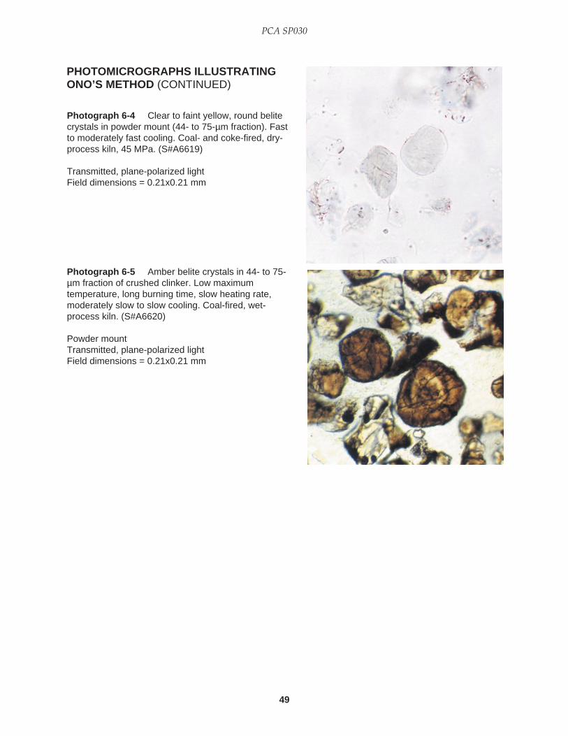
49
PCA SP030
PHOTOMICROGRAPHS ILLUSTRATINGONO’S METHOD (CONTINUED)
Photograph 6-4 Clear to faint yellow, round belitecrystals in powder mount (44- to 75-µm fraction). Fastto moderately fast cooling. Coal- and coke-fired, dry-process kiln, 45 MPa. (S#A6619)
Transmitted, plane-polarized lightField dimensions = 0.21x0.21 mm
Photograph 6-5 Amber belite crystals in 44- to 75-µm fraction of crushed clinker. Low maximumtemperature, long burning time, slow heating rate,moderately slow to slow cooling. Coal-fired, wet-process kiln. (S#A6620)
Powder mountTransmitted, plane-polarized lightField dimensions = 0.21x0.21 mm
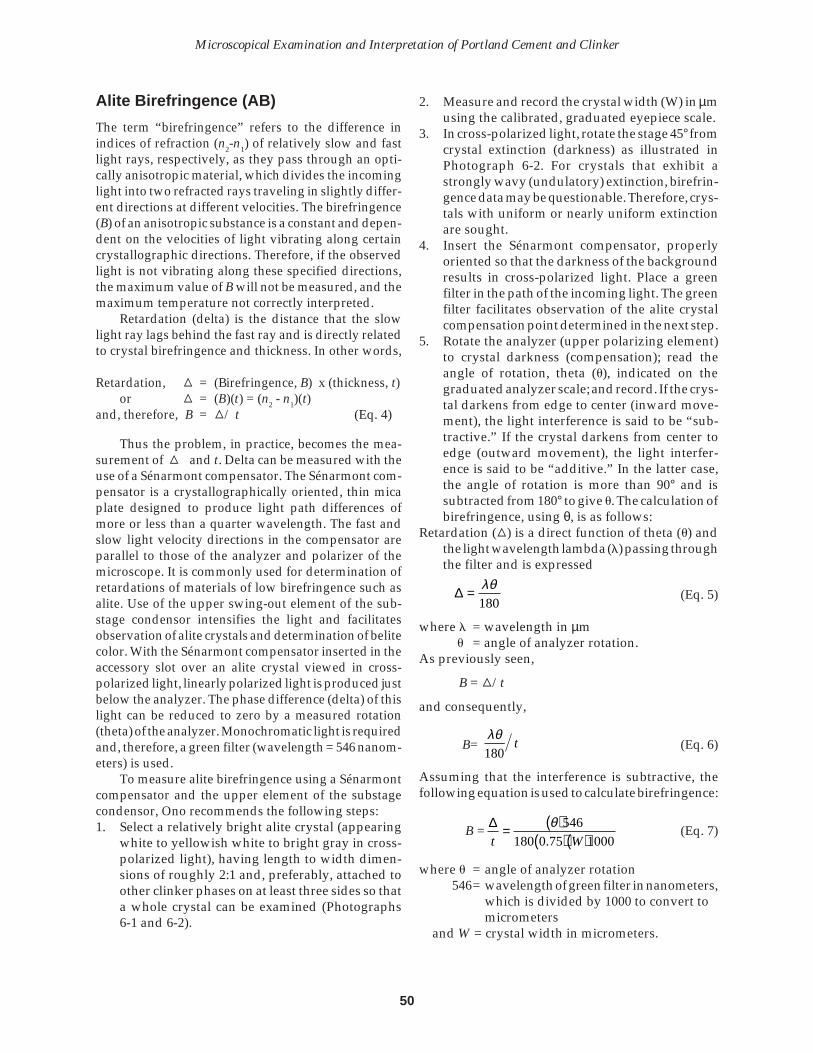
50
Microscopical Examination and Interpretation of Portland Cement and Clinker
Alite Birefringence (AB)
The term “birefringence” refers to the difference inindices of refraction (n2-n1) of relatively slow and fastlight rays, respectively, as they pass through an opti-cally anisotropic material, which divides the incominglight into two refracted rays traveling in slightly differ-ent directions at different velocities. The birefringence(B) of an anisotropic substance is a constant and depen-dent on the velocities of light vibrating along certaincrystallographic directions. Therefore, if the observedlight is not vibrating along these specified directions,the maximum value of B will not be measured, and themaximum temperature not correctly interpreted.
Retardation (delta) is the distance that the slowlight ray lags behind the fast ray and is directly relatedto crystal birefringence and thickness. In other words,
Retardation, C = (Birefringence, B) x (thickness, t)or C = (B)(t) = (n2 - n1)(t)
and, therefore, B = C/ t (Eq. 4)
Thus the problem, in practice, becomes the mea-surement of C and t. Delta can be measured with theuse of a Sénarmont compensator. The Sénarmont com-pensator is a crystallographically oriented, thin micaplate designed to produce light path differences ofmore or less than a quarter wavelength. The fast andslow light velocity directions in the compensator areparallel to those of the analyzer and polarizer of themicroscope. It is commonly used for determination ofretardations of materials of low birefringence such asalite. Use of the upper swing-out element of the sub-stage condensor intensifies the light and facilitatesobservation of alite crystals and determination of belitecolor. With the Sénarmont compensator inserted in theaccessory slot over an alite crystal viewed in cross-polarized light, linearly polarized light is produced justbelow the analyzer. The phase difference (delta) of thislight can be reduced to zero by a measured rotation(theta) of the analyzer. Monochromatic light is requiredand, therefore, a green filter (wavelength = 546 nanom-eters) is used.
To measure alite birefringence using a Sénarmontcompensator and the upper element of the substagecondensor, Ono recommends the following steps:1. Select a relatively bright alite crystal (appearing
white to yellowish white to bright gray in cross-polarized light), having length to width dimen-sions of roughly 2:1 and, preferably, attached toother clinker phases on at least three sides so thata whole crystal can be examined (Photographs6-1 and 6-2).
2. Measure and record the crystal width (W) in µmusing the calibrated, graduated eyepiece scale.
3. In cross-polarized light, rotate the stage 45° fromcrystal extinction (darkness) as illustrated inPhotograph 6-2. For crystals that exhibit astrongly wavy (undulatory) extinction, birefrin-gence data may be questionable. Therefore, crys-tals with uniform or nearly uniform extinctionare sought.
4. Insert the Sénarmont compensator, properlyoriented so that the darkness of the backgroundresults in cross-polarized light. Place a greenfilter in the path of the incoming light. The greenfilter facilitates observation of the alite crystalcompensation point determined in the next step.
5. Rotate the analyzer (upper polarizing element)to crystal darkness (compensation); read theangle of rotation, theta (u), indicated on thegraduated analyzer scale; and record. If the crys-tal darkens from edge to center (inward move-ment), the light interference is said to be “sub-tractive.” If the crystal darkens from center toedge (outward movement), the light interfer-ence is said to be “additive.” In the latter case,the angle of rotation is more than 90° and issubtracted from 180° to give u. The calculation ofbirefringence, using θ, is as follows:
Retardation (C) is a direct function of theta (u) andthe light wavelength lambda (l) passing throughthe filter and is expressed
∆ = λθ
180(Eq. 5)
where l = wavelength in µmu = angle of analyzer rotation.
As previously seen,
B = C/t
and consequently,
B= λθ180
/ t (Eq. 6)
Assuming that the interference is subtractive, thefollowing equation is used to calculate birefringence:
B = ∆t W
= ( )( )( )
θ 546
180 0 75 1000.(Eq. 7)
where u = angle of analyzer rotation546= wavelength of green filter in nanometers,
which is divided by 1000 to convert tomicrometers
and W = crystal width in micrometers.

51
PCA SP030
The equation, therefore, reduces to:
B = θW
0 004044.( ) (Eq. 8)
This formula has been found by the author toproduce an apparent birefringence which, more oftenthan not, easily fits with what is thought to be thecorrect interpretation of kiln conditions or what hasbeen determined in the laboratory. However, Onohas stated that 0.75 times the particle width (insteadof crystal width) is the best approximation of t (Ono,1981). The ratio of vertical thickness to horizontalwidth of the particles on the slide is statistically 0.75,according to Ono. Alite birefringence is determinedon particles with thicknesses ranging from 30 to 60 µmand horizontal dimensions of 40 to 80 µm, correspond-ing approximately to the same order of magnitude asthe alite and belite crystal sizes, which, along with thebelite color, are determined on the same slide in 10 to15 minutes. Ono, however, recommends that a combi-nation of polished sections and powder mounts is thepreferred method of examination, as does the presentwriter. This topic will be discussed later in this section.
If true crystal thickness is required, the crystalmay be rolled in refractive-index oil to the propermeasurable position by tapping the cover glass with apencil point while observing the particle motion. Ahigh-viscosity liquid such as marine varnish (n = 1.63)facilitates the technique of crystal rolling and mea-surement.
The Babinet compensator, rather than theSénarmont, is preferred by some microscopists. TheBabinet compensator fits into a specifically built slotabove the objective of the microscope and is com-prised of two precisely cut, crystallographically ori-ented wedges of quartz. A crystal is set 45° fromextinction in cross-polarized light and the 546-nanometer filter is placed on the light source. As thesliding portion of the compensator is slipped into theoptical path, the crystal being examined will slowlydarken as light compensation occurs. If the crystal isin the subtractive position, the thinnest part willdarken first, followed by darkening of the center. Thecompensator reading lens is inserted, focused, and ascale, observed on the cross-hairs, is read andrecorded as “X.”
The formula for calculating retardation, ∆, withthe Babinet compensator is:
C= al546(X-b) (Eq. 9)
where a and b are constants determined by the com-pensator manufacturer and normally given intwo wavelengths (l): 546.1 or 589.3 nanometers.
The thickness, X, is determined by rolling thecrystal, or it can be approximated by other techniquesas previously described. Alite birefringence is calcu-lated as follows:
Birefringence, B = C/t (100) (Eq. 10)
A third method of determining alite birefringencerequires a refined appreciation for the various colorsof alite as seen in cross-polarized light and also the useof a third-order red accessory plate (gypsum). TheMichel Lévy Color Chart, which is a required part ofthis technique, can be found in almost all opticalmineralogy textbooks and is included in the back ofthe present publication. The Chart graphically dis-plays the relationships between interference color,retardation, thickness, and birefringence. The proce-dure utilizing alite interference color, a gypsum acces-sory plate, and the Michel Lévy Color Chart is asfollows:1. Select a bright alite crystal (one that exhibits the
maximum interference color in cross-polarizedlight) and rotate the microscope stage so that thecrystal is at its extinction position (dark).
2. Insert the gypsum accessory plate (wavelength= 530 nanometers). The interference color of thealite crystal will be first-order red (530 nanom-eters), as seen on the Chart.
3. Rotate the stage 45° to the left of the extinctionposition, and match the yellow interference colorof the crystal observed in the microscope to thesame shade of yellow on the Chart. Mark theposition of color identity on the Chart. Rotate thestage 45° to the right of extinction, observe theblue-green crystal color, find it on the Chart, andmark the location.
4. Measure the distance between the color identitypoints on the Chart and divide by 2.
5. Measure the crystal thickness (µm) by rolling thecrystal, or estimate the thickness by determiningthe crystal width and multiplying by 0.75.
6. On the side of the Chart labeled “Thickness,”find the line corresponding to the value deter-mined in Step 5. From the left end of the line,measure the distance finally determined in Step4. Project a line diagonally to the upper right andread the graphically determined birefringenceat the top of the chart.One of the principal problems with this method of
determining birefringence is the variance in colorinterpretation between workers and even within asingle observer. With practice, however, this tech-nique is quite fast and correlates well with methodsusing other accessory plates. One can easily distin-

52
Microscopical Examination and Interpretation of Portland Cement and Clinker
guish relatively high and low birefringences in pow-der mount without charts or calculations after becom-ing familiar with the optical characteristics of alite.Obviously, this requires frequent practice and an un-biased observation, as does all reliable microscopy.
Alite birefringence observed in clinker is a func-tion of burning temperature and crystal modifica-tions. High temperature, trigonal (R) alite has a bire-fringence of 0.007 to 0.010. The disordered monoclinicvariety (M1), retaining some of the R form, and the M3form (Maki and Chromy, 1978) have birefringences of0.005 to 0.007. An ordered M1 form has a birefringenceof 0.004 to 0.005. The triclinic form (T2) has a birefrin-gence less than 0.004.
The birefringence of alite is also a function ofwhere it forms in a clinker nodule. Small alite crystalsnear a nest of free lime have low birefringence. Largeor medium crystals near a belite nest have high bire-fringence. Isolated crystals blown around in the high-temperature burning zone have very high birefrin-gence (Ono, 1980c).
Belite Size (BS)
This parameter is the average of the longest diametersof approximately 10 crystals. Typical belite crystals areseen in Photographs 6-3 through 6-5. In selecting thecrystals for measurement one should look for crystalsrepresenting the most commonly occurring crystalsize. Belite size, in the writer’s opinion, is best deter-mined with polished, etched sections or thin sections.
At a temperature of approximately 1100°C to1200°C alpha-prime belite forms as small crystals; atabout 1400°C the crystals change to alpha and exhibitconsiderable growth. Crystal size of belite, therefore,is primarily dependent on the time maintained above1400°C—the burning time.
Belite Color (BC)
Perhaps the most important of the four parameters,belite color is estimated using an arbitrary numericalscale: Amber (1), Yellow (2), Pale Yellow (3), and Clear(4). Crystals with abundant dotlike inclusions (fromexsolution) are given a ranking of 1. One shouldexamine approximately 10 belite crystals which arenot coated with interstitial phases, noting the mostcommonly occurring color. Rowe (letter, 1985) recom-mends observation of belite color in a powder mountmade with the minus 100-mesh (0.149 mm) fraction.Use the upper swing-out element of the substagecondensor to intensify the light.
As in the estimation of alite birefringence, oneshould eliminate the extremely large and the very
small crystals. A thin section is particularly advanta-geous in estimating belite color because the observedbelite crystal is a cross section and, therefore, uncom-plicated by attached ferrite. The observer should not beunduly influenced by extremes in the range of colorsobserved. Examination of “true” color and crystal sur-faces of silicates is facilitated by a study of samplesfrom which the matrix phases have been extracted witha potassium hydroxide and sugar solution (Hawkins,1982). See Chapter 11 for details of this extraction.Belite colors are illustrated in Photographs 6-3, 6-4, and6-5.
Belite in the alpha form can contain up to 2 percentalumina, 2 percent iron oxide, and 3 percent sodiumoxide, but only traces of these oxides in the alpha-prime form. The amounts of these impurities, there-fore, are functions of the cooling rate. As cooling andexsolution occur, belite changes from clear to faintyellow, to yellow and amber, depending on the rate oftemperature decline concentrating impurities adjacentto the lamellae (Ono, 1995). Slowly cooled, rotary kilnclinker produces belite, the center of which is Type Ichanging to Type Ia with dotted and cross striations,while the rim of Type I changes to Type III, and theround surface and spherical aspects of high-tempera-ture alpha remain (Ono, 1995). Very slow cooling re-sults in dispersed dotlike impurities in otherwise clearbelite. Belite colors observed in transmitted light havebeen generally correlated with data from reflected-light examination of polished sections (Ono, 1981).
Kawamura and Mizukami (1969), while investi-gating the relation between raw feed containing vari-ous particle sizes and different Blaines of quartz andfeldspar, described belite rings. Ono (1995) stated thatbelite rings with diameters of 300- to 600-µm developfrom coarse silicates (quartz, feldspar, and shale), form-ing large Type I crystals (40 to 60 µm) which arecolorless even in slowly cooled clinkers.
Use of Ono’s Table to Interpret KilnConditions and Formula to Predict 28-day Mortar-Cube Strength
Each of the four parameters for the kiln conditionsgiven in Table 6-1 (heating rate, maximum tempera-ture, time at maximum temperature, and cooling rate)is given numerical ranking of 4, 3, 2, or 1, according tothe data determined by microscopy. Consequently, thepredicted 28-day mortar-cube strength can be calcu-lated with Ono’s equation (1995), which is slightlydifferent from his previously published equation andapparently replaces the table of 28-day strengths usedearlier (1981). Ono’s latest equation (1995), stated instandard units, is:

53
PCA SP030
F(28d) = 25.309 + 0.513AS + 2.027AB + 0.334BS +2.179BC MPa (Eq. 11)
(standard deviation = 1.67 MPa for the strengthrange 29.42 to 44.13 MPa)
For example, assume the following data: alite size(AS) 50 µm (slow heating rate), alite birefringence (AB)0.0085 (high maximum temperature), belite size (BS) 30µm (long time at maximum temperature), and belitecolor (BC) is pale yellow (moderately fast cooling).Therefore, the numerical rankings for these parametersare 1, 4, 4, and 3, respectively. Thus, F(28d) is calculated:
F(28d) = 25.309 + 0.513(1) + 2.027(4) + 0.334 (4) +2.179(3)= 41.18 MPa
Free-lime contents of 1 to 2 percent may result in28-day mortar strengths less than the predicted value(Ono, 1980c). In addition, Ono states that the alitebirefringence value should be increased by 0.001 inthe table if the magnesium oxide content of the clinkeris greater than 1.8 percent; the table value should bedecreased by 0.001 if the magnesium oxide is less than1.2 percent. A negative correction factor of 0.001 is alsorecommended by Ono if the sulfate (SO3) content isgreater than 1.25 percent.
In a letter response to questions about clinkerquality, burning conditions, and prediction of strength,Ono (1980) made the following statements:1. The effect of alite and free lime percentages and
Blaine on the 28-day strength is small and cor-rection is usually unnecessary.
2. Poorly burned clinker frequently contains manysmall belite clusters. If the raw mix containscoarse quartz grains, belite clusters appear evenin well-burned clinker, and the alite size has awide range.
3. Alkalies increase 7-day strength, but the effecton 28-day strength is small. Osbaeck (1979) saidthat alkalies decrease 28-day strength.
4. Grindability of quickly cooled clinker is good.Amber belite is ground at the last stage. J.M. Butt(1974) stated that good grindability of quicklycooled clinker is due to plenty of micropores inthe interstitial phase.
5. A section of alite parallel to the trigonal plane(001) is weakly etched compared with a sectionof another direction in a twinned crystal. In azoned crystal, a zone with higher birefringenceis strongly etched compared to a zone withlower birefringence. If polishing and etchingtechniques are proper, etching degree is an ex-cellent index of hydraulic activity of alite.
Ono stated (letter, 1977) that an alite birefrin-gence slightly higher than 0.007 could be written0.007+ and ranked as “good”; a birefringence slightlylower than 0.008 may be written as 0.008- and rankedas “excellent.”
Ono readily admits that the powder-mount pa-rameters used to interpret burning conditions aremerely expedients and that they provide data in whichvariations reflect relative changes in kiln conditions.Herein lies, perhaps, the salient point of the Ono method:If the method can be used to determine correctly therelative changes in the individual variables (maximumtemperature, burning time, rate of heating, and rate ofcooling), then the use of the method can be rewardingbecause immediate changes in some of the major en-ergy-related production processes can be made. Thatthe parameters are somewhat imprecise or that theirapplication is not as rigorous as one might want shouldnot detract from the essential purpose of the method:detecting relative changes in kiln conditions.
Successful application of Ono’s theories and tech-niques in routine clinker production and in kiln start-up operations is recorded by Prout (1979) with powdermounts and polished sections providing essential data.Prout strongly asserts that application of the Ono tech-nique should be more “qualitative than quantitative”and that the data should be interpreted relatively foroptimum benefit (Prout, oral communication, 1984).Furthermore, Prout used the predicted strength as an“Index Number” for relative comparison, a procedurewith which the present writer is in complete agreement.
Using a somewhat different approach, Knöfel(1989) reliably predicted the 28-day mortar strengthwith a simple formula containing microscopically de-termined percentages of alite, belite, aluminate, andferrite. The equation is: F28 = 3(alite) + 2(belite) +aluminate - ferrite. F28 is termed the “characteristicstrength.” The equation is designed for use within acement plant where production conditions over theperiod of investigation are virtually identical.
A bivariant linear equation, containing factors suchas phase percentages, crystal sizes, morphology andcluster indexes, for predicting the 28-day mortarstrength was presented by Sinha, Rao, and Akhouri(1991). The standard deviation was said to be 17.9 kg/cm2, agreeing closely with the actual strength.
A paper by Takagi and Kawashima (1980) showsthe effects of various kiln conditions on alite, belite, andinterstitial phases. These authors present a clinker“Character Index,” a collection of parameters which,when plotted against compressive strength at 28 days,forms a sigmoidal curve. The Ono parameters figuresignificantly in the formulation of the Character Index,as seen in the following list of phase characteristics:

54
Microscopical Examination and Interpretation of Portland Cement and Clinker
1. Alite—crystal size, optics, zoning, fringing, habit,crystal form;
2. Belite—crystal size, optics, morphology and tex-ture, recrystallization, “gelappster,” exclusionof impurity;
3. Interstitial—crystal size and optics.Kiln variables with which some of the phase
characteristics are correlated are kiln speed, coating ofburning zone, burning zone temperature, flame length,burning zone length, temperature gradient, coolingrate, and atmosphere.
The Ono parameters were found to be the domi-nant variables (above chemical composition, includ-ing the normal moduli and porosity) in an experimentto explain problems of grindability (Kawamura andothers, 1982). These authors gave the following equa-tion to predict the Blaine surface area (BL) with theOno method, stating the microscopical factors in thearbitrary scale of 4, 3, 2, and 1 as given previously:
BL = 1513 + 171AS + 167AB + 417BS - 153BC (Eq. 12)correlation coefficient = 0.840
standard deviation = 97 cm2/gn = 30
where AS = alite sizeAB = alite birefringenceBS = belite sizeBC = belite color
Large belite nests were shown to be indicative ofpoor grindability, even though the same clinker mayhave relatively high porosity. Clusters of belite crystalsremained undivided even at the final grinding stage.
Using alite birefringence and belite size, Uedaand Suzuki (1985) were able to monitor the variablecalorific value of coals and make adjustments in thekiln conditions to maintain clinker quality.
The results of microscopy by the Ono method areconsidered an important part of the data base in acomputerized multivariate analysis conducted rou-tinely for cement quality control in plants of the OnodaCement Company in Japan (Aizawa, 1985). Micro-scopical data are said to be helpful in making frequentadjustments in kiln parameters, clinker silo operation,and adjustment of cement fineness. The continuallyupdated analysis involves the following process vari-ables: burning zone temperature, kiln outlet clinkertemperature, secondary air temperature, extractionair temperature, kiln rotation torque, nitrous oxide,percent clinker passing the 5-mm screen, and literweight. In some Japanese cement plants, clinkers arerecycled until the microscopical targets have beenmet, according to Uchikawa (1992).
Application of the Ono Method to the evaluation ofkiln conditions in relation to cement hydration pro-cesses and types of added sulfate (natural gypsum, betahemihydrate, and anhydrite II) is the subject of a paperby Uchikawa and others (1984). These authors showedthat the “burning degree,” defined as an exponentialmathematical function of maximum temperature (T),critical temperature To = 1250°C, and the retention time(time required to keep the clinker above To), corre-sponds closely to the amount of free lime, liter weight,and microscopical data. The highest 28-day mortar-cube compressive strength (43.1 MPa) was obtainedwith cement made from the well-burned clinker andgypsum. Well-burned and poorly burned clinker werecharacterized by the following factors:
Well burned Poorly burnedLiter weight (kg/L) 1.25 1.10Free lime (%) 0.17 1.64Alite size (µm) 40.00 20.00Alite birefringence 0.007 0.004Belite size (µm) 30.00 10.00Belite birefringence 0.012 0.018
Ono (1991) listed some of the characteristics ofpoorly burned clinker: free lime greater than 4.5%,tightly packed large free-lime nests, belite nests with asurrounding of small alites, high porosity, a loose frame-work of free lime and alkali aluminate, and a flowpattern of matrix into the free-lime nest. Well-burnedclinker was said to contain small free lime and octahe-dral periclase from dolomite and coarse aluminate andferrite, resulting from equilibrium crystallization.
Personal correspondence from Ono (1979)listed some of his preliminary conclusions relatinggrindability, burning conditions, and clinker micro-structure:1. Clinkers with high Hydraulic Modulus (HM),
defined as CaO/(SiO2 + Al2O3 + Fe2O3), are softerand more easily ground. (No precise values ofHM were given.)
2. The fine powder fraction of clinker is rich in alitefragments. The coarse fraction is rich in agglom-erates of small brown belite and agglomerates ofminute alite crystals combined with dark intersti-tial phase.
3. Well-burned clinker with a high VW, volumeweight, is difficult in coarse grinding (getting it topass the 1-2 mm sieve), but soft in fine grinding(<88 microns). VW is the weight of clinker nod-ules, 5-10 mm diameter, in a liter container. Opti-mum VW is approximately 1.35 kg/L.
4. High VW clinker is deficient in large pores, largerthan 1 µm (usually 50 to 500 µm), and rich in minute

55
PCA SP030
pores (less than 1 micron), actually approximately0.1 mm. The volume of minute pores is intimatelyconnected to grindability into a fine powder. Theminute pores seem to be gaps between the den-dritic structure of the interstitial phase.The volume weight (VW) of clinker, according to
Ono (1995), is [1.43 (1-porosity)]. VW for ordinaryclinker is 1.20 to 1.25 kg/L, and porosity is 0.13 to0.16 cc/cc.
Ono (1995) listed clinker characteristics in relationto burning degree, stating that well-burned clinker hasvolume weights from 1.30 to 1.37 kg/L, and porositiesof 0.04 to 0.07 cc/cc. Furthermore, well-burned clinkeris characterized with alite crystals ranging from 30 to40 µm, perhaps up to 60 µm, and dispersed belites from20 to 40 µm. In contrast, poorly burned clinkers havevolume weights of approximately 1.0 kg/L and porosi-ties of 0.25 to 0.35 cc/cc. Poorly burned clinker gener-ally has a wide range of alite crystal sizes (15 to 60 µm,averaging 30 to 40). In such clinkers belite aggregationsoccur in hollow spheres (bubbles) with diameters rang-ing from 200 to 400 µm, also in compact clusters. Belitecrystal sizes in poorly burned clinker were also said torange from 10 to 30 µm.
ADDITIONAL COMMENTS ON THE ONOMETHOD AND RECENT RESEARCH
Alite Birefringence
According to Ono, Kawamura, and Soda (1968), alitebirefringence is a function of maximum temperature inthe kiln load: the higher the temperature, the larger thebirefringence. Birefringence in Ono’s method is mea-sured on alite crystals in clinker particles mounted inRI oil and observed in transmitted, polarized light.
To date, more than 1500 alite birefringences havebeen determined on crystals in thin section by thepresent writer, using clinkers embedded with quartz inepoxy resin. Some of these results have been presentedin a microscopical comparison of North American andforeign clinkers (Campbell, 1979). The known birefrin-gence of quartz (0.009) was used to calculate the thick-ness of the section. No correction was made for differ-ential hardness relief on the thin-section surfaces. Av-erage alite birefringence determined by the thin-sec-tion method is 0.0044, with a standard deviation of0.00099. Maximum and minimum values are approxi-mately 0.0083 and 0.0022, respectively. A discrimina-tion among and within zoned crystals was not made.Powder-mount determinations of birefringences, us-ing Equation 8 and clinkers from the same samplesstudied in thin section, resulted in an average birefrin-
gence of 0.0078, standard deviation of 0.0016, andmaximum and minimum values of 0.0104 and 0.0034,respectively.
It is clear that the Ono formula (Eq. 7) gives anapparent birefringence and, perhaps, should be indi-cated “B*” (read “B star”). Ono is in agreement with thissuggestion (1981). Nevertheless, although one does notdetermine the true birefringence with Ono’s method,the data can be validly interpreted to indicate relativechanges in maximum burning temperature, interpre-tations which can be corroborated by other microscopi-cal data. The apparent birefringence as an indicator ofmaximum temperature is being used by many micros-copists in Asian and North American cement plants.
One of the principal difficulties in the determina-tion of apparent birefringence by powder mount isfinding proper crystals, those with relatively brightinterference colors and length to width ratios of ap-proximately two. Extreme difficulty in satisfying theratio requirement may, in itself, be indicative of burn-ing conditions such that the desired crystal develop-ment was inhibited.
Pennell (1987) discussed the differences betweenalite birefringences determined with thin sections (thepresent author’s data) and powder mounts, illustratingthe fact that the latter determination was not accurate,but concluding that the values may be “tolerable” forcorrelation purposes.
The problem of measurement of crystal thickness(t) for the determination of alite birefringence in pow-der mounts has been the subject of much discussion.Prout (oral communication, 1984) finds that the thick-ness can be approximated by the equation (length +width)/2, giving a reasonable apparent birefringence.
The factor of 0.75 in the denominator of Eq. 7 foralite birefringence was statistically derived to accountfor deviations between true and observed birefrin-gences of an alite crystal in which the “X” vibrationdirection is not exactly parallel to the microscope stageand the “Y” and “Z” directions are not precisely known.In order to minimize this deviation, which lessens thebirefringence, a crystal-thickness-to-particle-width ra-tio of 3/4 is assumed (Ono, letter, 1978). The clinkerparticle, in this case, was illustrated to contain only partof an alite crystal.
Phillips (1971, p. 101) stated, “Loose fragmentsconsistently lie on their broad side, and it is safe toassume that fragment thickness is slightly less than thenarrow dimension that he can see and measure.”
Preliminary data from optical techniques with pow-der mounts to determine apparent maximum and mini-mum indices of refraction of alite, using an RI oil of 1.72and its dispersion curves, were discussed by Stark(1980). Stark found a birefringence range of 0.0030 to

56
Microscopical Examination and Interpretation of Portland Cement and Clinker
0.0065 with this technique, compared to a range of0.0030 to 0.010 by the “standard” Ono procedure inwhich the factor 0.75W is used; Ono-method values forbirefringence were consistently higher.
A different interpretation of alite has been given byFundal (1982), who stated that alite crystals are twinnedindividuals of a lower symmetry which imitate a highersymmetry (a mimetic relationship). The monoclinicform of alite was said to have an index of refraction of1.72 and a birefringence of approximately 0.0050. Tri-clinic alite was reported to be polysynthetically twinnedin a fused clinker and have a birefringence of 0.0020.Alite birefringence, however, exhibits two average val-ues in Fundal’s Table 1 (1982): 0.0043 (monoclinic) and0.0023 (trigonal and possibly triclinic). In fused clinkerthe monoclinic form was observed zonally in thin sec-tion on the interior triclinic form. The zoning relation-ship was not revealed by polished section etches withHF-vapor or 4 percent HNO3 in ethanol. Trigonal alitewas seen associated with void deposits of alkali sulfate.
Consequently, Fundal (1982) reports results con-tradictory to Ono’s theory of kiln interpretation, namely,that:1. Determination of alite birefringence in powder
mount is subject to an error of approximately0.0006 and that a “petrographers rule” of crystalwidth being equal to 4/3 crystal thickness is notvalid as a short cut.
2. Alite birefringence determined in thin section,using quartz as an internal thickness standard, isa suitable method. However, a correlation withburning temperature was not evident.Fundal (1982) measured crystal length (L) as an
approximation of thickness (t). Fundal’s alite birefrin-gences are, therefore, quite similar to true birefringencebecause the denominator (L) in the birefringence equa-tion is relatively large. Fundal (F.L. Smidth report, Jan.2, 1978) stated that the variations in D/L, where D =crystal thickness, account for the variations in alitebirefringence by Ono’s technique, and that small, flatcrystals give high birefringences using the Ono for-mula. A “form factor” was said to represent the bire-fringence determined by Ono’s method. Statisticallytreated data concerning crystal dimensions and bire-fringence are greatly needed.
In response to Fundal (1982), Lee (1983) pointedout the bimodality of alite birefringence determined byMaki and Kato (1982), who demonstrated relationshipswith magnesium oxide content in the crystal. Lee re-stated the conclusion by Maki and Kato that the M1(monoclinic) phase appears pseudotrigonal in an X-raypowder-diffraction pattern. Lee believed that Fundal’scomparison of alite compositional and optical datawith a tectosilicate solid-solution series, such as plagio-
clase feldspar, or with a nesosilicate series, such asolivine and monticellite, did not suffice to explain thevariation in alite birefringence.
Nagashima, Asakura, and Uda (1983) have shownwith laboratory experiments that the M1 variety of aliteprecipitated from the melt is always observed at themaximum burning temperature but it is converted toM3 with longer holding time. Slow burning results inthe M3 variety even though the holding time is long (upto two hours). These authors also suggested that (1)alite birefringence reaches a maximum in a shorter timewhen the burning temperature is higher and the rawmix finer, (2) alite impurities decrease with an increasein the maximum temperature, and (3) correlations be-tween alite birefringence and magnesium oxide con-tent do not exist and a high content of impurities is notessential for making M3 stable at ambient temperature.
Asakura, Uda, and Kawabata (1984) classified aliteinto four varieties according to birefringence and tex-ture determined by microscopical examination of plantclinkers: (1) coarsely crystalline alite (M1 variety) witha birefringence of 0.003, possibly formed in slow burn-ing; (2) zoned crystals with round, dusty M1 cores thathave low birefringence (0.003) and M3 rims character-ized by fine inclusions and relatively high birefrin-gence (0.005), the round M1 cores thought to exhibit theeffects of possible remelting with M3 precipitating fromthe melt on the original crystal; (3) dusty M3 alite, witha birefringence of 0.004 to 0.005, interpreted to resultfrom the second variety (described above) by succes-sive addition of heat; and (4) euhedral, prismatic crys-tals with a birefringence of 0.006 and without fineinclusions, said to be a possible result of rapid heating.
Chen, Conjeaud, and Lehoux (1985) estimated burn-ing zone temperatures with three techniques: byburnability studies of the raw mix, by electron-micro-probe analysis of alite in clinker, and by birefringence ofalite. The latter method was said to be the least accurate,due possibly to clinker magnesium oxide and sulfatecontents, kinetics of alite crystallization from a melt,raw mix particle size, and variable calcination rates.
Nagashima and others (1988) in a laboratory studyclarified some of the kiln conditions for the M1 and M3varieties of alite. The M3 variety, formed by rapidburning, is characterized by fine crystal size, and pris-matic, euhedral, clear crystals with few inclusions. TheM1 variety, formed by relatively slow burning or undera low temperature, is typically coarse. With prolongedholding time M1 changes to M3 with high birefringenceand numerous fine inclusions, giving the crystal adusty appearance. M3 was shown to have a slowerhydration at 3 days but at later ages develops a rela-tively dense paste and higher strength than M1 at water-cement ratio of 0.5.
57
PCA SP030
In a series of laboratory experiments, Maki andothers (1995) described a very fast first stage and rela-tively slow second stage of alite crystallization con-trolled by diffusion of CaO from the interstitial liquid.Nucleation rate is high at first, forming many smallcrystals, then as CaO supersaturation in the liquid de-creases, crystal growth was dominant, developing crys-tals by deposition on the basal pinacoid. With a rela-tively slow heating rate (10°C/min), both nucleationand growth continued slowly, forming well-faceted,relatively stable M3 alite.
In a series of plant experiments with burning zonetemperatures of approximately 1315°, 1530°, and 1600°C,Marchiset and others (1990) found an increasing silicatesize and decreasing alite birefringence with increasingtemperature. The greater amount of magnesium in thealite at relatively low burning temperature, producingmore M3 than M1, was given as the reason for theincrease in birefringence. These authors demonstratedthat a relatively low burning-zone temperature (1315°C)produced a comparatively reactive clinker, resulting inan increase in the quantity of ions in solution whenmixed with water, and an early precipitation of ettringite.Furthermore, the quantity of gypsum necessary to ac-celerate hydration was less than that required for clin-ker burned at a high temperature (1600°C) which wassaid to render the C3A less reactive.
Mor and Perez (1994) presented a critical evaluationof Ono’s method (powder mount only) using laboratoryheating stages, concluding that the alite size and alitebirefringence did not correlate. Correlation was said tobe much better with regard to belite size and color. Thecorrespondence between laboratory and industrial kilnmicroscopy was seriously questioned and differences inenvironmental conditions, mainly atmospheric compo-sition, were alleged to be responsible.
Finally, because the measurement of apparent bire-fringence is fraught with so much controversy and theMethod seems to lack standardization, the present writerproposes that alite crystals for determination of B* havea length-to-width ratio of approximately 2 to 1, withcrystal widths in the range of 15 to 25 µm, and silicatecrystal size measurements be made in the polishedsection. One does not have to use transmitted polarizedlight, however, to interpret maximum temperature. Onostated (1980d) that the “etching degree” of alite couldalso be used instead of alite birefringence to interpretmaximum temperature. “Etching degree” is covered inChapter 3.
Alite Size
Suzukawa, Kono, and Fukunaga (1964), in a laboratorystudy with an electric furnace, studied the effects of
high-temperature burning at 1500° to 1700°C and burn-ing times ranging from 0.5 to 60 minutes. The contentof alite increased and belite decreased with increasingburning temperature; alite crystal size distributioncurves were Gaussian for the clinker burned at 1600°and 1700°C, but skewed toward the finer sizes forclinker burned at 1500°.
Alite crystal size, according to Fundal (1982), isprimarily a function of raw mix coarseness: large rawmix particles promote crystallization of large alite crys-tals because of relatively large compositional gradientsdeveloped during burning. Crystal size, therefore, in-creases with the increasing temperature normally nec-essary to sinter the hard-to-burn coarse raw feeds.Crystal volume measurements (π/6)(L2W) where Land W represent crystal dimensions. Fundal found thatthe larger the crystal volume, the poorer the burnability.
Lee (1983) stated that kiln variables such as feedgranulometry, feed composition, fuel characteristics,and alkali sulfur circulation are more or less fixed in anormal kiln. Therefore, alite size reflects the heatingrate, as Ono has maintained in many papers.
Bruggemann (1988), using the linear traverse tech-nique for phase abundance, demonstrated that small,lattice-defective, alite crystals produced in kilns withsteep temperature profiles and short residence timesimprove grindability and cement quality. Ono’smethod, utilizing only a few crystals in a powdermount, was said to “give doubtful results.”
Older and Maula (1986), in a laboratory study,concluded that variations in heating rate, burningtemperature, duration of burning at maximum tem-perature, and cooling rate produced only small butdistinct variations in alite size; of these, burning tem-perature had the most noticeable effect. Cement hydra-tion was accelerated with increasing burning tempera-ture, but after one day was little affected by otherburning variables.
Asaga and others (1989) stated that a slow heatingrate produced larger crystals of alite and that burningtemperature had no effect on size. Belite grew largewhen the interval at high temperatures was long. An-nealed clinker produced small alite and changed thebelite diffraction pattern. These researchers also dem-onstrated rapid early hydration of small alite, followedby a slowdown, and relatively rapid hydration of largebelite crystals. Annealed alite and ferrite were said tohydrate rapidly at first, also followed by a slowdown.
Scheubel (1988) found that the alite chord lengthcould be used to construct a cumulative crystal sizecurve, the data from which were used to evaluate heatingrates and retention times in various kiln systems. High-quality clinkers were said to have uniform granulometry,small silicate crystals, and easy grindability.

58
Microscopical Examination and Interpretation of Portland Cement and Clinker
Extremely coarsely crystalline clinkers were pro-duced by a melting process described by Khadllkarand others (1992). Raw mixes with 4 to 6 mm particlesizes were burned at temperatures of 1700° to 1800°C inan induction furnace and cooled in compressed air orquenched in water. The molten metal that formed hadto be extracted with a magnet before grinding thecement. Alite and belite crystal sizes were said to berelatively large by many times in the air-cooled samplescompared to the water-quenched materials. The matrixin the air-cooled clinker was described as a “eutecticmixture of finer alite and aluminate.” Compressivestrength at 7 days (Blaine = 320 m2/kg) reached asmuch as 320 kg/cm2 (31.4 MPa). Later strengths werenot reported.
The microscopy of two clinkers produced within10 seconds by electron beam radiation at 1.2 MEV wasdescribed by Handoo and others (1992). Aliteand belite appear well formed, with crystal sizes of10 to 16 µm. Mortar strength at 28 days was said to be470 kg/cm2 (46.1 MPa).
The relationship of silicate percentage and crystalsize to SO3 is described by Strunge, Knöfel, and Dreizler(1990) who state that with increasing SO3 in the clinker,alite content decreased and belite increased, the matrixremaining without substantial changes. With increas-ing SO3 content from 0% to 2.6%, alite crystal sizesbecome larger by a factor of three, the crystals having anincreasing idiomorphic form. Nucleation of alite de-creases with additional SO3 due to reductions in liquidphase viscosity and, perhaps, the stabilization of belite.Alkali sulfate in the clinker was said to retard setting,while sulfate within the silicates accelerates setting. Thedepth and detail of these investigations are too great tobe summarized here, and the reader is urged to studythis reference further. These data clearly illustrate thatalite crystal size is not simply a function of burning rateand raw feed coarseness.
Bruggemann and Bentrup (1990) studied 27 port-land cement clinker samples microscopically and withlaboratory prepared cements attempted to determinethe correlations with prism strengths at ages of 2, 7, and28 days, at three Blaine finenesses: 2800, 3800, and4800 cm2/g. Increasing cement strength with smallalite crystal size was found to be statistically significantif the cements were grouped according to soluble alka-lies. Strength prediction reliability was improved if (1)the ratio of alite content determined microscopically tothe C3S content calculated with the Bogue equation and(2) the ratio of the calculated C3S content to the averagechord length of the alite were used.
Continuing with the investigation of silicate crys-tal characteristics, Uchida, Shirasaka, and Hirao (1991),in a laboratory study of three raw meals, varied burn-
ing rate, maximum temperature, retention time, andcooling temperature and measured the clinker silicateparameters by the Ono Method. The size of alite changedfrom 60 to 30 µm as the burning rate increased from 10°to 40°C/min. Birefringence of alite changed from 0.002to 0.008 as maximum temperature climbed from 1450°to 1600°C. Size of belite increased from 5 to 40 µm asretention time extended from 5 to 30 minutes. Belitecolor changed from amber to clear as the cooling tem-perature increased from 1100° to 1500°C. Using pore-size definitions of less than 1 µm, 1 to 20 µm, and greaterthan 20 µm, and calculating the pore volumes repre-sented in each of these categories, it was shown that asburning conditions improved, the ratio of the less than1-µm void volume to the other volumes (except totalpore volume) increased.
Ikeda and Ichikawa (1992) in a laboratory studyshowed that heating rates from 33° to 55°C/min re-sulted in instability of alite crystal growth, and pro-duced larger crystals with morphological irregularityand formation of zonal structures with sulfate at 1.87%.Relatively minor changes occurred with potassium ox-ide at 1.34%. With increasing heating rates, alite crystalgrowth became unstable, resulting in larger crystals,morphological irregularity, and formation of zonal struc-tures. The crystal size of alite was said “to not varymonotonously with heating rates.” These authors cor-relate increasing heating rate, SO3, and P2O5 with in-creasing alite crystal size.
Centurione and Tonhi (1995) in a laboratory studystated that increases in burning temperature or resi-dence time resulted in larger alite; alite crystal length-to-width ratio increased with heating rate.
A partial least-square regression analysis was ap-plied by Svinning and Bremseth (1993) on alite crystalsize and various process parameters, showing that alitesize accounted for only approximately 40% of the totalvariance and that an increase in the >60-µm crystalsoccurred with decreasing secondary air temperaturemeasured in the cooler. Statistical analyses of this type,in the present writer’s opinion, are greatly needed inour industry to decipher relative importance of themany kinds of measurements.
Wolter (1985) correlated modern kiln characteris-tics (length, diameter, speed, firing, rotational speed,degree of calcination, and thermal profiles) with prop-erties of the clinkers (silicate crystal size, clinkergranulometry, grindability), showing that great differ-ences exist in clinker characteristics. The relatively high-quality clinker was said to be produced in kilns in whichthe maximum temperature of the feed material is nohotter than 1420°C and the length of time required forpassage through the “transition and burning zones” isshort, leading to clinkers with small silicate crystals,

59
PCA SP030
uniform clinker gradation, and ease of grinding. Ashort preheater kiln with a length to diameter ratio of 10to 1, a 95% calcination prior to the transition zone, anda maximum of 65% tertiary air was described as therecommended kiln system.
Maas and Kupper (1994) described a series ofburnability experiments in a horizontal “gradient” ro-tary furnace in which variable (but controlled) heatingand cooling rates up to 200°C per minute were routinelyutilized; a cooling rate of 400°C per minute from amaterial temperature of 1450° to 900°C was also studiedwith this furnace. Among the many findings reportedare: (1) With rapid heating a more rapid conversion tobelite occurred than with slow heating. (2) After thestart of liquid phase formation and the initial alitedevelopment there was a continuous decrease in belitecontent, regardless of the heating rate. (3) The delayedappearance of alite in the less reactive raw meal wasconspicuous. (4) Alite formed as a melt precipitate. (5)With a burning temperature of 150°C above the tem-perature of the onset of alite formation, all materialsneeded a residence time of 25 to 30 minutes to achievemaximum alite development. A burning temperatureof about 250°C above the temperature at which aliteformation starts reduced the necessary residence timefor maximum alite development by about 15 to 20minutes. (6) Silicate crystals became coarser as the resi-dence time required at sintering temperature increased;therefore, when optimizing a burning process, effortsmust be made to produce crystals which are as small aspossible. (7) The heating rate of the material to sinteringtemperature had no great influence on the sizes of thesilicates. (8) The more rapid the heating rate, the smallerthe free lime crystallite size.
Belite Color
The color of belite crystals, according to Ono, is depen-dent on their contained impurities and the degree towhich the impurities are exsolved as the crystal cools.Slow cooling permits time for exsolution to occur and arelatively dark (amber-colored) crystal results. In acement, one commonly observes a wide range of belitecolors, extending from clear to amber and probablyrepresenting a range of cooling rates or crystal compo-sitions (and other kiln variations). Therefore, a modalcolor, that is, one representing the most frequentlyoccurring color, is given principal importance. If beliteclusters (nests) comprise a large portion of the observedbelite, then their color is given the most weight in adetermination of cooling rate. As discussed later, abun-dant large belite nests are detrimental to clinker qualityand their effect may lessen that of an excellent coolingrate. In a thin section, it is not unusual to find a wide
range of belite color in different belite nests in a singleclinker nodule, the color differences being due to local“micro” variations in raw feed chemistry (Ono, letter,1980). Belite color has been said to be the most impor-tant of the Ono parameters (Dorn, oral communica-tion, 1980).
Belite colors in cements with 28-day mortarstrengths greater than 48 MPa and cements withstrengths less than 38 MPa were studied by Campbell(1994b). The belite color data gave only gross trendsand weak correlations with strength, suggesting, asexpected, that many other cement factors such as aliteand belite size, alite birefringence, number and sizesof belite nest fragments, crystal chemistry, fineness,etc., also exert strong controls on the 28-day strength.Positively sloping regression lines relating clear andpale yellow crystals, occurring singly and in nests, andnegatively sloping lines relating yellow and ambercrystals, including those with abundant dotlike impu-rities, also occurring singly and in nests, are evident.Higher correlation coefficients appear likely from awithin-plant study where the production variablesare not as disparate as those represented in the samplesjust discussed and strength data, perhaps, should berestricted to the gain beyond 14 days.
Certain “observational problems” can skew belitecolor data and complicate the interpretation of coolingrate, and the following comments are reproducedalmost verbatim from Campbell (1994b):1. It is well known in mineralogy that many miner-
als may be strongly colored in hand specimenbut colorless when viewed as small particlesunder the petrographic microscope (e.g., micro-cline, fluorite, quartz, dolomite, calcite). With asmaller particle size, such as the 10- to 15-µmfraction of the cement or crushed clinker, onemight find a tendency to judge a crystal frag-ment color to be clear when actually the color ofthe original whole crystal was pale yellow. Thenatural color of belite crystals in plane-polarizedlight, somewhat like interference colors in cross-polarized light, are functions of crystal thicknessand the degree to which the crystal has beenallowed to exsolve its impurities, most of whichare retained within the particle. Large wedge-shaped fragments of single belite crystals tend tobe clearer and always have lower interferencecolor on the thin side of the particle than on thethick side. In the present research the relativethick side was chosen as the color indicator. A“daylight-blue” filter, constant light intensityand aperture setting are standard. For nests that survive the KOH-sugar treat-ment, a common situation in the author’s method

60
Microscopical Examination and Interpretation of Portland Cement and Clinker
of extraction, the problem of crystal color is not aseasily resolved. Small round belite crystals arecommonly clear (in anyone’s definition), butwhen stacked in a nest like a handful of marbles,the clear color may appear tinted because of tinymasses of ferrite or other phases buried deeply inthe nest between the belite crystals and thusprotected from the KOH-sugar solution, or dueto Becke line effects. When grinding the clinker ina mortar and pestle, all of the chosen subsamplemust pass the 75-µm screen, if one wants todetermine the number of belite nest fragmentsand their crystal colors. When counting nestedcrystals along a line of traverse, one must con-sider each crystal (nested or single) and make thebest judgment possible. Separate recording ofnested versus single crystals may be helpful insome studies. Colorless belite crystals, in manycases, are seen to have lamellar extensions intransmitted light as whole grains and in polishedthin sections. To the present writer, this indicatesslow to moderately slow cooling. Tiny belite crystals formed as a surficial de-composition of the alite during slow cooling havealways been clear in the writer’s observations;secondary belite (formed out of the matrix dur-ing cooling) is also clear, perhaps because thesecrystals have little to exsolve. Research is neededon this point. Amoeboid crystals are rarely col-ored; dendritic crystals have never been observedto be colored in the writer’s experience. Ono’sbelite color interpretation seems most applicableto “properly” formed crystals.
2. “Boundary-line colors” refers to colors falling be-tween the major categories of clear, pale yellow,yellow, and amber. In other words, pale yellow toone observer is obviously yellow to another, evenwhen each person is being as objective as possible.The problem is not unique to cement microsco-pists. An attempt at a photographic belite colorstandard is presented in this book.
3. The “color” one observes is not altogether a prod-uct of exsolution, but also of crystal microstruc-ture. Changes in light-ray velocity and direction(refraction and double refraction) when passingthrough materials of nearly identical refractiveindex (belite lamellae, for example) commonlyproduce faint bands of color or light intensity asthe waves interfere. These effects can be linear, thatis, occurring along the boundaries of adjacent lamel-lae, easily visible in thin wedge fragments, or morecomplexly formed by intersecting lamellae. TheBecke line itself may have a yellowish color inliquid with a refractive index of 1.715 or Hyrax™
(1.70), and care should be taken not to confuse itwith crystal color. The level of focus should besuch that the Becke line is just outside the belitecrystal for color determination. Even the Beckeline around alite can give the crystal a faint yel-lowish color as the focus is raised or lowered.
4. Certain cations such as chromium, manganese,and, perhaps, aluminum from refractory bricksand other sources can produce a range of greenand yellow variations in belite. These causes ofcoloration do not appear to be related to coolingrate, however, much research remains. The ab-sence of yellow and amber belite in some slowlycooled white cement clinker suggests that iron isthe primary colorant in other portland cements.Various cations from petroleum-derived wastefuels may also color certain phases in the clinker.A brief report discussing the microscopy of one of
the ICMA Exchange Program clinker samples waspublished by the present writer in 1994. The dispari-ties between Bogue phase percentage calculations andmicroscopy, vagaries in alite birefringence, and prob-lems in belite color judgement suggest a need forstandardized sizes for silicate crystals for the coolingrate and maximum temperature interpretations.
Fundal (1982) also presented a different interpre-tation of belite stating that, like alite, belite seems to bemimetic, occurring in the trigonal system and trans-forming during cooling to an orthorhombic (alpha-prime form), twinned symmetrically andpseudohexagonally around the gamma optical vec-tor. Index of refraction was said to vary little from 1.72,with a birefringence of 0.015 for both synthetic (labo-ratory) and industrial clinker. Fundal pointed out thecommon occurrence of different belite crystal colors inthe same nest and, using the ratio of clear to browncrystals, concluded that the method based on colorwas useless for kiln control. The ratio was said to bepossibly influenced by decrepitation and rebuildingof nodules during burning and by different types ofraw mix. Clear crystals were thought to be producedby crystallization from the melt, and nests were pro-duced from quartz, feldspar, low-lime marl, schist,diopside, hornblende, and other types of particles.
Colorless belite, according to Lee (1983), can oc-cur as very small inclusions in alite and contains verylittle impurity. Large-crystal, ringlike belite nests (fromcoarse alkali feldspar) are also colorless because ofiron-oxide deficiency. These occurrences of belite,therefore, do not reflect the cooling rate. Consequently,Ono (1978) recommends color observation of roughly 20-µm belite crystals in order to judge the cooling rate.
If the cement or clinker contains belite only asfringes (coatings) on alite crystals, then the use of

61
PCA SP030
belite color and size in Ono’s method appears virtuallyimpossible because of the scarcity of observable belitein powder mount. The other parameters, alite size andbirefringence, however, remain and can be utilized.
Using microprobe techniques in a laboratory study,Ikabata, Honda, and Yoshida (1988) described some ofthe positive effects of rapid cooling rates, beginning ata temperature of approximately 1350°C, concluding,among other things, that belite containing approxi-mately 0.7% to 0.8% alkali is best for 28- to 91-daystrength development. Annealing the clinker clearlyresulted in “discharging” alkalies and other impurities.
Systematic studies relating the effects of slow heat-ing and cooling in vertical shaft kilns (VSK) in terms ofthe “Ono parameters,” or related observations, arescarce. Raina and Janakiraman (1993) described themicroscopical characteristics of VSK clinkers producedfrom overlimed, underlimed, and optimally limed rawfeed with varying fineness and retention time. Abun-dant free lime was produced in both the underlimedand overlimed materials. The underlimed clinker hada Bogue C2S of 33.2%; microscopically it was 42%.
Relatively small alite (15 to 18 µm) characterized theoverlimed mix, which also had a very low liter weight(950 g/L) and 6.8% free lime; percent alite and crystalsize increased with increasing temperature and reten-tion time. Increasing fineness of the interground cokewas related to the absence of evidence for reducingconditions (yellow nodules and metallic iron). Increas-ing the burning zone temperature to 1450°C inhibitedthe production of gamma belite.
A multiregressional equation predicting the 28-day mortar cube strength was presented by Rao,Akhouri, and Sinha (1992), the data coming from ro-tary and vertical shaft kiln clinkers. The prediction hasa standard deviation of 17.9 kg/cm2, utilizing alite andbelite percentages and average crystal sizes.
Detailed microscopical characteristics of clinkersfrom vertical shaft kilns, compared to laboratory burns,are presented by Ahluwalia and Raina (1992).Alite and belite crystal sizes in plant clinkers averagedapproximately 21 and 19 µm, respectively, possiblyaccounting for high mortar strengths (44.8 MPa at28 days).

62
Microscopical Examination and Interpretation of Portland Cement and Clinker

63
PCA SP030
CHAPTER 7
Microscopical Interpretation of Clinkers
from reported observations of clinkers made by manyauthors in laboratory experiments and in cement plants.The author of each observation and interpretation isindicated, although it is very difficult in many cases toestablish historical originality. The reader should beaware that such a listing of observations and interpre-tations taken out of context from the referenced publi-cations can be misleading, and that general applicationof the interpretation could be risky.
Unfortunately, some interpretations stated by dif-ferent authors in the table are contradictory and thereader is left to his or her experience to determine thecorrect statement. Additionally, some observations mayhave more than one correct interpretation, that is,multiple causes. Some of the stated correlations maynot be cause and effect relationships. Furthermore,some of the referenced work appears less than system-atic. Such problems point out the need for research,and, indeed, it is hoped that the contents of this publi-cation serve to stimulate scientific cement research,particularly quantitative microscopy with a statisticalapproach, using techniques that group and character-ize the sets of observations and genetic conditions.
The photographs in this section are illustrations ofclinkers examined and interpreted by this writer, withemphasis on the use of Ono’s interpretive table (Table6-1). It is important to note that individual photo-graphs may not depict all the microscopic featuresnormally associated with the stated interpretation ofkiln conditions, the interpretation having been drawnfrom the results of several techniques of examinationand study of several clinkers in the sample. Designa-tions such as 42.8 MPa in the photomicrograph cap-tions indicate reported 28-day mortar-cube strength.
Alite and belite, which comprise most of portlandcement clinker, have a close genetic relationship and,as evident in the previous chapter, are not easilyseparated for microscopical discussion. Alite crystals,for the most part, quickly nucleate and grow withinthe melt, exhibiting dissolution, recrystallization, anddecomposition, the latter to belite (Maki, 1982, andMaki, Morikoshi, and Takahashi, 1985). Belite canform during the heating stage as well as in the coolingstage of the burning process. Thus, the microstruc-tures that one may observe in the silicates reflect arather complex genetic history. The matrix is an inti-mate, finely microcrystalline intergrowth of alumi-nate and ferrite which formed during the very earlycooling stage above 1300°C (Bye, 1983).
Consequently, instead of a chapter organizationbased primarily on genetic sequence (see Hofmänner,1973; Chromy, 1974; Butt and Timashev, 1974; Ono,1981, 1995; Chromy, 1982; and Gartner, 1985), theobservations and interpretations in this chapter arelisted first with some of the relatively large-scale fea-tures of clinkers and then, for the most part, accordingto phase abundance. Rather than in a lengthy narra-tive survey of interpretive details of clinker phases,stated by various authors in many published papers,the information is presented in tabular form. Table 7-1presents, in a double column, a list of (a) clearlyrecorded observations on the left and (b) verbatimpublished interpretations, associations, or correlationson the right. This survey is not a critical review.
Seldom does a single observation of a particularmicroscopic feature provide sufficient evidence towarrant a widely applicable interpretation. Most in-terpretations given herein represent conclusions drawn
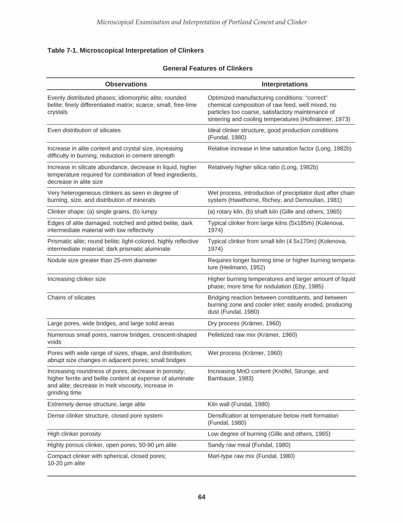
64
Microscopical Examination and Interpretation of Portland Cement and Clinker
Table 7-1. Microscopical Interpretation of Clinkers
General Features of Clinkers
Observations Interpretations
Evenly distributed phases; idiomorphic alite; rounded Optimized manufacturing conditions: “correct”belite; finely differentiated matrix; scarce, small, free-lime chemical composition of raw feed, well mixed, nocrystals particles too coarse, satisfactory maintenance of
sintering and cooling temperatures (Hofmänner, 1973)
Even distribution of silicates Ideal clinker structure, good production conditions(Fundal, 1980)
Increase in alite content and crystal size, increasing Relative increase in lime saturation factor (Long, 1982b)difficulty in burning, reduction in cement strength
Increase in silicate abundance, decrease in liquid, higher Relatively higher silica ratio (Long, 1982b)temperature required for combination of feed ingredients,decrease in alite size
Very heterogeneous clinkers as seen in degree of Wet process, introduction of precipitator dust after chainburning, size, and distribution of minerals system (Hawthorne, Richey, and Demoulian, 1981)
Clinker shape: (a) single grains, (b) lumpy (a) rotary kiln, (b) shaft kiln (Gille and others, 1965)
Edges of alite damaged, notched and pitted belite, dark Typical clinker from large kilns (5x185m) (Kolenova,intermediate material with low reflectivity 1974)
Prismatic alite; round belite; light-colored, highly reflective Typical clinker from small kiln (4.5x170m) (Kolenova,intermediate material; dark prismatic aluminate 1974)
Nodule size greater than 25-mm diameter Requires longer burning time or higher burning tempera-ture (Heilmann, 1952)
Increasing clinker size Higher burning temperatures and larger amount of liquidphase; more time for nodulation (Eby, 1985)
Chains of silicates Bridging reaction between constituents, and betweenburning zone and cooler inlet; easily eroded, producingdust (Fundal, 1980)
Large pores, wide bridges, and large solid areas Dry process (Krämer, 1960)
Numerous small pores, narrow bridges, crescent-shaped Pelletized raw mix (Krämer, 1960)voids
Pores with wide range of sizes, shape, and distribution; Wet process (Krämer, 1960)abrupt size changes in adjacent pores; small bridges
Increasing roundness of pores, decrease in porosity; Increasing MnO content (Knöfel, Strunge, andhigher ferrite and belite content at expense of aluminate Bambauer, 1983)and alite; decrease in melt viscosity, increase ingrinding time
Extremely dense structure, large alite Kiln wall (Fundal, 1980)
Dense clinker structure, closed pore system Densification at temperature below melt formation(Fundal, 1980)
High clinker porosity Low degree of burning (Gille and others, 1965)
Highly porous clinker, open pores, 50-90 µm alite Sandy raw meal (Fundal, 1980)
Compact clinker with spherical, closed pores; Marl-type raw mix (Fundal, 1980)10-20 µm alite

65
PCA SP030
Large pores, nontwinned belite, large alites High SO3 (Tsuboi and Ogawa, 1972)
Rough pore surfaces Low temperature burning (Tsuboi and Ogawa, 1972)
Very porous clinker consisting of small bright grains with Underburned clinker (Törnebohm, 1897)rounded edges
Porous, alite-rich, lumpy clinker, some with dense centers; Excessive hard burning (Long, 1982a)dusty clinker, ring and “stalagmite” formation in kiln andcooler; large alite crystals; sparkling luster of clinker;lowered cement strength
Friable clinkers surrounded by a deposit of alite crystals Very hard burning of high silica ratio materials (Pollitt,alone 1980)
Clinker nodules of varying composition Inadequate blending of feed or segregation in kiln(Long, 1982a)
Clinker inhomogeneity Lower reactivity of ash, too short retention time atclinkering temperature, high ash content, lump coal forprecalcining carbon-rich fly ash as a raw material,waste-derived fuels containing graphite (Sprung, 1985)
Nests Excessive particle size in raw mix (greater than 0.1 mm)(Gille and others, 1965)
Streaks and spots in clinker Nonhomogeneity of raw mix, segregation of dust in airducts during transfer to silo or in kiln (Gille and others,1965)
Spots in clinker Local increase of individual components of raw material;low burning degree (temperature too low or burning timetoo short); low lime content (Gille and others, 1965)
Overall crystal size Function of temperature, time, and chemical composi-tion of surrounding material; absorbed nests and priornonhomogeneities (Gille and others, 1965)
Large crystals High temperature, long burning time, surroundingmaterial is low lime (belite) (Gille and others, 1965)
Large crystal cements Unsatisfied charges on broken crystal surfaces resultingin agglomerations, abnormal setting characteristics, andincreased grinding time (Hansen, 1977)
Large segregated silicates, belite nests, poor matrix Long burning zone, maximum temperature belowdistribution, high free lime 1500oC, preheater kiln (DeHayes, Grady, and Vidergar,
1986)
Pronounced segregation of silicates and matrix Short residence time, high production rates, roller-millphases, wide alite size range, large crystals, raw grind, coarsely ground coal precalciner kilnsome > 100 mm, high porosity, relic coarse quartz grains (DeHayes, Grady, and Vidergar, 1986)
Large crystal size and narrow crystal size range Unfavorable grindability (Tachihata, Kotani, and Jyo,1981)
Overall increase in crystal size; alite more than belite, Lowering of feed to speed ratio, thinning clinker bedwhich tends toward yellow color depth as burning zone moves uphill (Rader, 1985)
Coarsely crystalline clinker High early strengths, abnormal setting problems(Hansen, 1980)
Table 7-1. Microscopical Interpretation of Clinkers (continued)
General Features of Clinkers
Observations Interpretations

66
Microscopical Examination and Interpretation of Portland Cement and Clinker
Coarsely crystalline clinker with a high degree of hydration High compressive strengths (Entin, Nekhoroshev, andper unit specific surface Sorochkin, 1980)
Hard, dense clinker, with large alite, plus soft, porous Variable burning, flushing (passage of charge tooclinker with low alite content rapidly through kiln), or excessive feed (Long, 1982a)
Small, poorly formed phases; very high porosity; uneven Flushing or sintering temperature is too low (Hofmänner,phase distribution; alite surrounded by large amounts of 1973)liquid phase; belite in clusters
Increase in specific crystal surface (surface area of solid Results in an increase in specific pore surface andparticles/volume of solid particles) and reduction in melt reduction of power requirement for grinding (Petersen,volume 1980)
Three zones in clinker: (a) Primary nodules (kiln ring fragments or nodules(a) Dense core formed before burning zone)(b) Intermediate porosity (b) Forms in burning zone(c) Cokelike (c) Forms between burning zone and cooler due to
heavy dust load (Fundal, 1980)
Dense core, high-porosity shell Agglomeration of dust (less than 1.0 mm) on nodulebetween burning zone and cooler inlet (Fundal, 1980)
Peripheral zones in clinkers Differentiation or segregation of melt during liquid stage ofgroundmass (Gille and others, 1965)
Fine clinker Soft burning, insufficient liquid phase; extreme hard burn-ing and abrasion of porous shells on clinkers; Mn mineraliser(large alite crystals) (Long, 1984b)
Dusty clinker: high porosity, “breaded” nodules, (a) Decomposition of outer clinker shell andagglomerated fine particles, alite-rich, large alite crystals, concentration of liquid phase in clinker core (Allegreand relatively scarce liquid phase and Terrier, 1960)
(b) Recycling of precipitator dust, reducing zones, lack ofAl2O3 in raw slurry (Hofmänner, 1973)
Dusty clinker (poor nodulization) and snowmen (a) Unfavorable temperature distribution(b) Too little melt(c) Too much coarse quartz, lime, slag(d) Heavy alkali circulation resulting in early crystal growth
of belite and free lime and large silicate crystal size(Miller, 1980)
Belite nest with dense, thick layer of alite with very Typical in dust formation (Fundal, 1980)porous outermost zones
Clinker dust with abundant belite clusters Inferior burnability (Fundal, 1980)
Dusty clinker, coarsely crystalline silicates, low-porosity Slow temperature rise, higher clinkering temperature,nodules, poor grindability longer time in burning zone and transition zone (Wolter,
1985)
Coal ash shells on clinkers and nests at boundary zones Nonuniform combustion of fuel and partial reaction onclinker surface; inadequate grinding of coal and distribu-tion (Krämer, 1960)
Clinker color: earth brown to light brown to dark brown to In order of increasing degree of burning (Gille and others,black with greenish brown hue 1965)
Table 7-1. Microscopical Interpretation of Clinkers (continued)
General Features of Clinkers
Observations Interpretations

67
PCA SP030
(a) Reddish brown (a) Abundance of Fe++
(b) Dark gray with reddish hue (b) Fe partly replaced by Mn(c) Slate gray (c) Normal clinker with Mg in greenish-brown ferrite
(Gille and others, 1965)
Gray-black clinker color Overall oxidizing environment (Long, 1982b)
Yellow-brown clinker colors Rapid cooling (Long, 1982b)
Gray color of clinker Burning under oxidizing or neutral conditions; MgO inlattice of aluminoferrite, presence of trivalent iron (Sylla,1981)
Gray color of clinker Burned under reducing conditions, cooled in air afterremoval from kiln at temperature greater than 1250oC(Sylla, 1981)
Brown clinker Burned under reducing conditions, cooled at approxi-mately 1250oC under reducing conditions, further cooled inair (Sylla, 1981)
Bleached region in clinker Localized extreme reduction due to partly burned coaldeposition (Long, 1982b)
Well-defined yellow band separating gray-black periphery Reducing environment with reoxidation (Long, 1982b)from brownish black core
Black, oxidized parts of same sample show usual Moderate reducing conditions (Woermann, 1960)features but with three sets of belite lamellae strictlyoriented crystallographically with host alite
Clinker is densely burnt, light brown; ferrite has distinctly Reducing conditions (Woermann, 1960)lower reflectivity than in normal clinker; calcium andiron sulfides
Disappearance of ferrite phase, iron transformed to Extreme reducing conditions (Woermann, 1960)metallic state, clinker color changes to white, alitedecomposition structures vanish
Brown-centered clinkers, larger alite, lower birefringence Reducing conditions; longer, cooler flame; reductions inset control and strength (Brugan, 1979)
Spotty, banded coloration Chemical differences or varying burning conditions (Gilleand others, 1965)
Green clinker nodules, chromium-rich green belite, Consumption of refractory brick during production at lessgehlenite matrix than optimum kiln capacity or excessive flame length for
rated capacity conditions (Brugan, 1979)
Greenish brown—greenish yellow Entrapped magnesium (Gille and others, 1965)
Clinker weight (liter) Varies as a function of total porosity (Gille and others,1965)
High liter weight High alite content (Brown, 1948); increased time of burningat high temperature (Hawkins, 1979)
Low liter weight MgO slightly high, CaO distinctly high; aggregated clinkers(Brown, 1948)
Hydration shells on clinker Air-exposed piles of clinker with “roofs” of partial hydration(Krämer, 1960).
Table 7-1. Microscopical Interpretation of Clinkers (continued)
General Features of Clinkers
Observations Interpretations

68
Microscopical Examination and Interpretation of Portland Cement and Clinker
PHOTOMICROGRAPHS OF GENERAL FEATURES OF CLINKERS
Green, yellow, and brown clinkers Addition of Cr+3, Ti+4, and Fe+3/Mn+2, respectively (Laxmi,Ahluwalia, and Chopra, 1984)
Weathered clinker and low Blaine fineness of cement Problems in thickening time and free water in oil-wellcement (Reeves, Bailey, and McNabb, 1984)
Table 7-1. Microscopical Interpretation of Clinkers (continued)
Photograph 7-1 Porous outer zone of clinker,surrounding relatively dense clinker core. Evenlydistributed, round, clear belite crystals and angularalite. Pores filled with epoxy. Moderately highmaximum temperature, long burning time, slow heatingrate, quickly cooled. Dry-process kiln with flashcalciner, 5000 tons/day. (S#A6621)
Thin sectionTransmitted, plane-polarized lightField dimensions = 0.53x0.53 mm
Photograph 7-2 Polished section of cement inepoxy, illustrating large multiphase (composite)particles and small, single phase particles, a typicalrelationship for most portland cements. (S#A6622)
Nital etchField dimensions = 0.38x0.38 mm
General Features of Clinkers
Observations Interpretations
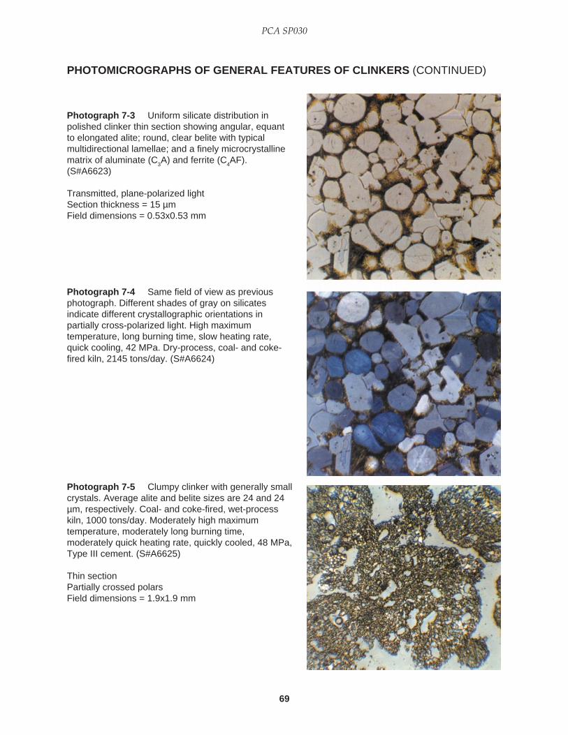
69
PCA SP030
Photograph 7-3 Uniform silicate distribution inpolished clinker thin section showing angular, equantto elongated alite; round, clear belite with typicalmultidirectional lamellae; and a finely microcrystallinematrix of aluminate (C
3A) and ferrite (C
4AF).
(S#A6623)
Transmitted, plane-polarized lightSection thickness = 15 µmField dimensions = 0.53x0.53 mm
PHOTOMICROGRAPHS OF GENERAL FEATURES OF CLINKERS (CONTINUED)
Photograph 7-4 Same field of view as previousphotograph. Different shades of gray on silicatesindicate different crystallographic orientations inpartially cross-polarized light. High maximumtemperature, long burning time, slow heating rate,quick cooling, 42 MPa. Dry-process, coal- and coke-fired kiln, 2145 tons/day. (S#A6624)
Photograph 7-5 Clumpy clinker with generally smallcrystals. Average alite and belite sizes are 24 and 24µm, respectively. Coal- and coke-fired, wet-processkiln, 1000 tons/day. Moderately high maximumtemperature, moderately long burning time,moderately quick heating rate, quickly cooled, 48 MPa,Type III cement. (S#A6625)
Thin sectionPartially crossed polarsField dimensions = 1.9x1.9 mm

70
Microscopical Examination and Interpretation of Portland Cement and Clinker
PHOTOMICROGRAPHS OF GENERAL FEATURES OF CLINKERS (CONTINUED)
Photograph 7-6 Extremely porous, sandy clinkershowing silicate crystal chains. High maximumtemperature, long burning time, slow heating rate,slowly cooled, 35 MPa. Coal-fired, wet-process kiln.(S#A6626)
Polished sectionNital etchField dimensions = 0.38x0.38 mm
Photograph 7-7 Variation in alite crystal sizes:clusters of small crystals (14 µm), noncluster crystals(38 µm). Round belite crystals in nest in upper center.High maximum temperature, long burning time,moderately slow heating rate, quickly cooled, 42 MPa.Gas-fired, dry-process kiln, 770 tons/day. (S#A6627)
Thin sectionTransmitted, plane-polarized lightField dimensions = 0.59x0.59 mm
Photograph 7-8 Inhomogeneous coarse feedresulting in highly porous clinker with extremelynonuniform distribution of silicates. Thin edges of thisrelatively thick thin section reveal a clear to pale yellowbelite color. High maximum temperature, long burningtime, moderately slow heating rate, quickly cooled,42-46 MPa. (S#A6628)
Transmitted, plane-polarized lightField dimensions = 1.9x1.9 mm

71
PCA SP030
PHOTOMICROGRAPHS OF GENERAL FEATURES OF CLINKERS (CONTINUED)
Photograph 7-9 Porous heterogeneous clinkershowing nests of dark, round belite surrounded byrelatively large alite crystals. Insufficient liquid phase.Very sandy raw mix with abundant metasiltstone. Highmaximum temperature, moderately short burning time,slow heating rate, moderately slow cooling rate. Gas-fired, dry-process kiln, 3000 tons/day. (S#A6629)
Polished sectionNital etchField dimensions = 0.53x0.53 mm
Photograph 7-10 Amber to yellow belite in large,sharply bounded nests and clear, angular alite crystalswith a wide range of sizes and nonuniform distribution.Insufficient liquid phase. Feed contains abundantcoarse metasiltstone particles. Estimated free lime =1.5% to 2.5%. Gas-fired, dry-process kiln. Highmaximum temperature, moderately short burning time,slow heating rate, moderately slow cooling. (S#A6630)
Thin sectionTransmitted, plane-polarized lightField dimensions = 0.60x0.60 mm
Photograph 7-11 Extremely heterogeneous clinkercontaining large concentrations of loosely packedyellow-amber belite and alite with a wide range ofcrystal sizes and, like the belite, a nonuniformdistribution. Free lime is abundant (dark, roundcrystals). Sandy, silica-rich raw feed with coarsequartz. Gas-fired dry-process kiln, 3000 tons/day.(S#A6631)
Polished sectionNital etchField dimensions = 0.53x0.53 mm
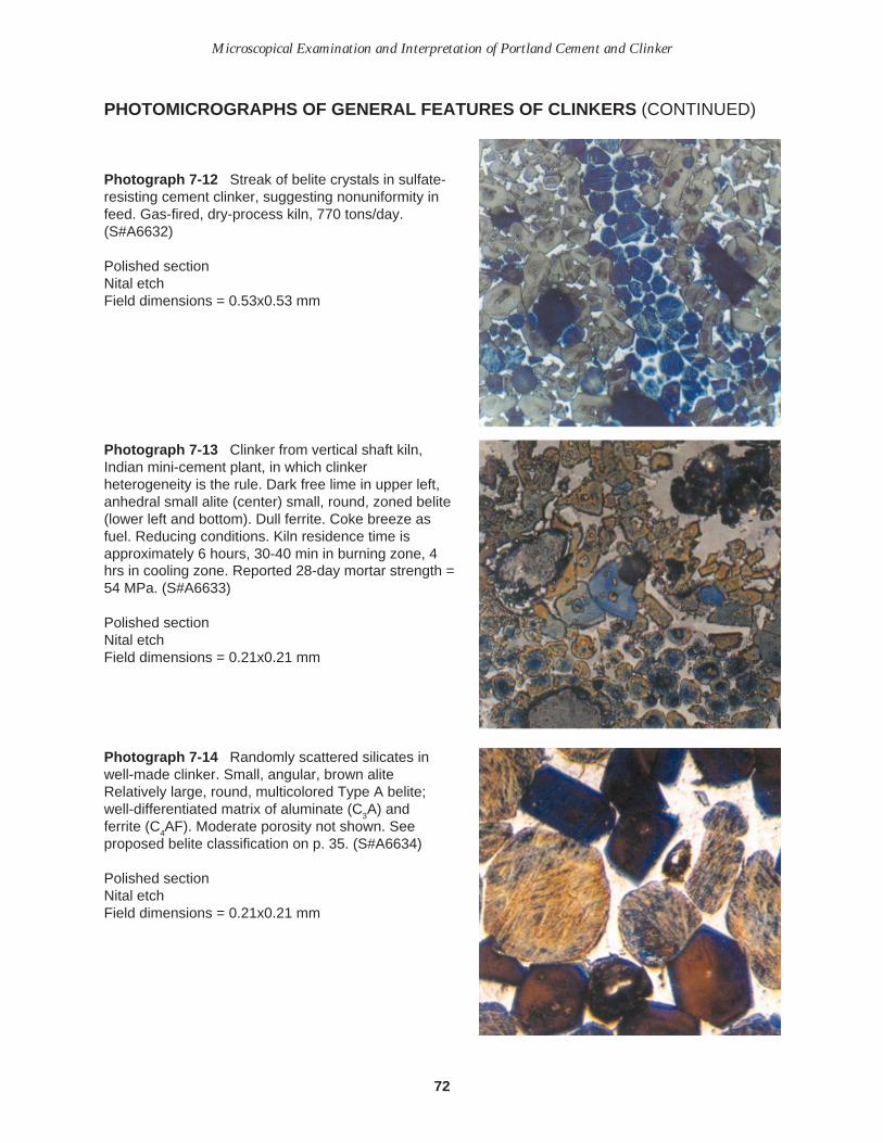
72
Microscopical Examination and Interpretation of Portland Cement and Clinker
PHOTOMICROGRAPHS OF GENERAL FEATURES OF CLINKERS (CONTINUED)
Photograph 7-12 Streak of belite crystals in sulfate-resisting cement clinker, suggesting nonuniformity infeed. Gas-fired, dry-process kiln, 770 tons/day.(S#A6632)
Polished sectionNital etchField dimensions = 0.53x0.53 mm
Photograph 7-13 Clinker from vertical shaft kiln,Indian mini-cement plant, in which clinkerheterogeneity is the rule. Dark free lime in upper left,anhedral small alite (center) small, round, zoned belite(lower left and bottom). Dull ferrite. Coke breeze asfuel. Reducing conditions. Kiln residence time isapproximately 6 hours, 30-40 min in burning zone, 4hrs in cooling zone. Reported 28-day mortar strength =54 MPa. (S#A6633)
Polished sectionNital etchField dimensions = 0.21x0.21 mm
Photograph 7-14 Randomly scattered silicates inwell-made clinker. Small, angular, brown aliteRelatively large, round, multicolored Type A belite;well-differentiated matrix of aluminate (C
3A) and
ferrite (C4AF). Moderate porosity not shown. See
proposed belite classification on p. 35. (S#A6634)
Polished sectionNital etchField dimensions = 0.21x0.21 mm
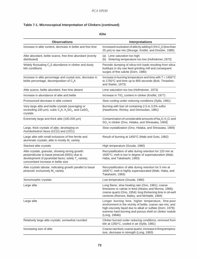
73
PCA SP030
Table 7-1. Microscopical Interpretation of Clinkers (continued)
Increase in alite content, decrease in belite and free lime Increased nucleation of alite by adding 0.5% C3S (less than
20 µm) to raw mix (Strunge, Knöfel, and Dreizler, 1985)
Alite abundant, belite scarce, free lime abundant (evenly (a) Lime saturation too highdistributed) (b) Sintering temperature too low (Hofmänner,1973)
Widely fluctuating C3S abundance in clinker and dusty Periodic dumping of silica-rich loads resulting from silica
kiln conditions buildups in dry raw feed grinding mill and consequentsurges of fine calcite (Dorn, 1980)
Increase in alite percentage and crystal size, decrease in Increase in burning temperature and time with T = 1450°Cbelite percentage, decomposition of C
3A to 1750°C and time up to 800 seconds (Butt, Timashev,
and Starke, 1973)
Alite scarce, belite abundant, free lime absent Lime saturation too low (Hofmänner, 1973)
Increase in abundance of alite and belite Increase in TiO2 content in clinker (Knöfel, 1977)
Pronounced decrease in alite content Slow cooling under reducing conditions (Sylla, 1981)
Very large alite and belite crystals (averaging or Burning with fuel oil containing 2.5 to 3.5% sulfurexceeding 100 µm), cubic C
3A, K
2SO
4, and CaSO
4(Hawthorne, Richey, and Demoulian, 1981)
crystals
Extremely large and thick alite (100-200 µm) Contamination of considerable amounts of Na2O, K
2O, and
SO3 in clinker (Ono, Hidaka, and Shirasaka, 1969)
Large, thick crystals of alite, developing on Slow crystallization (Ono, Hidaka, and Shirasaka, 1969)rhombohedron faces (0112) and (1011)
Large alite with small inclusions of fine ferrite and Result of burning at 1450°C (Maki and Goto, 1982)aluminate crystals; alite is mostly M
1 variety
Stacked alite crystals High temperature (Gouda, 1980)
Alite crystals, granular, showing strong growth Recrystallization of alite during retention for 120 min atperpendicular to basal pinacoid (0001) due to 1600°C; melt is low in degree of supersaturation (Maki,development of pyramidal faces; solely T
2 variety; Haba, and Takahashi, 1983)
concomitant increase in belite size
Alite crystals tabular, indicating growth parallel to basal Recrystallization of alite during retention for 5 min atpinacoid; exclusively M
3 variety 1600°C; melt is highly supersaturated (Maki, Haba, and
Takahashi, 1983)
Xenomorphic crystals Low temperature (Gouda, 1980)
Large alite Long flame, slow heating rate (Ono, 1981); coarselimestone or calcite in feed (Akatsu and Monna, 1966);coarse quartz (Ono, 1954); long thickening time in oil-wellcements (Reeves, Bailey, and McNabb, 1984)
Large alite Longer burning time, higher temperature, lime-poorenvironment in the vicinity of belite; coarse raw mix; andhigh-viscosity liquid due to alkali or sulfate (Dorn, 1979);extreme hard burning and porous shell on clinker nodule(Long, 1984b)
Relatively large alite crystals, somewhat rounded Clinker burned under reducing conditions, removed fromkiln at 1350°C, cooled in air (Sylla, 1981)
Increasing size of alite Coarse raw feed, coarse quartz, increase in firing tempera-ture, decrease in strength (Long, 1983)
Alite
Observations Interpretations
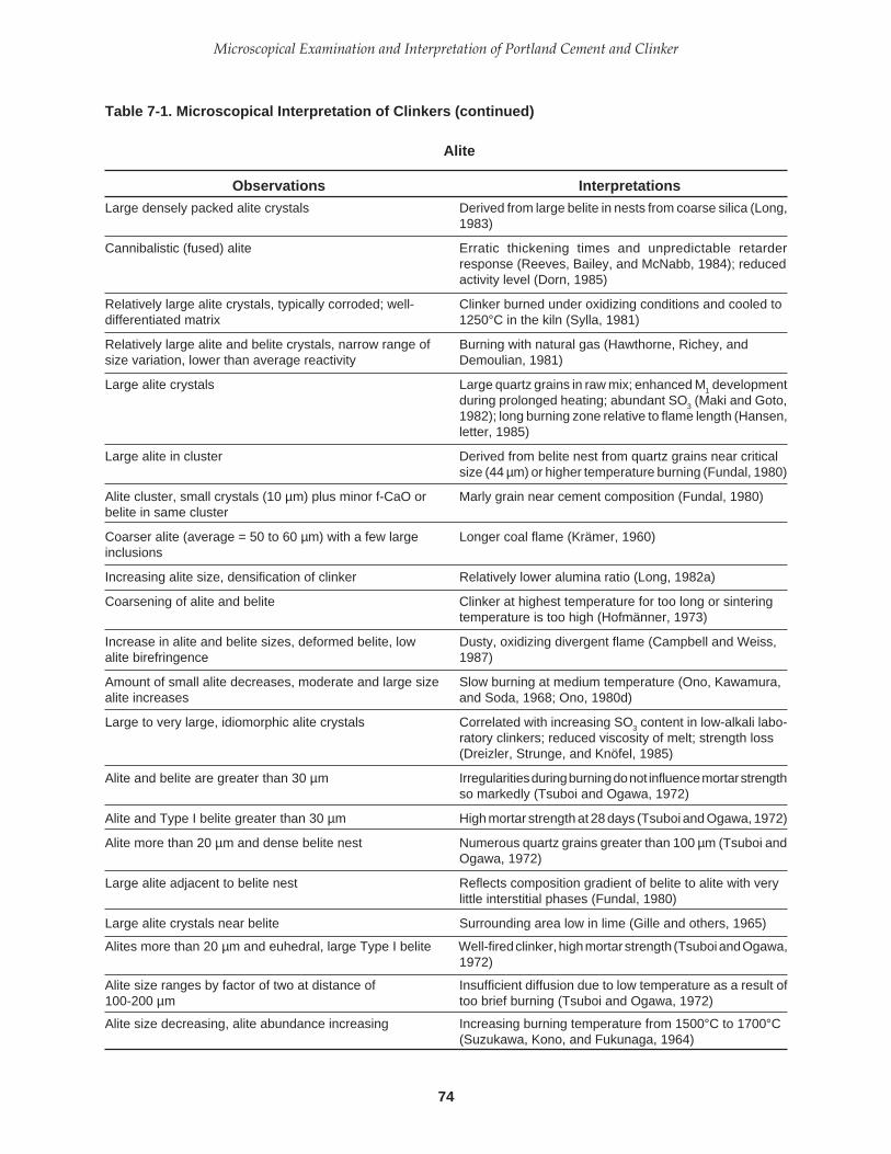
74
Microscopical Examination and Interpretation of Portland Cement and Clinker
Large densely packed alite crystals Derived from large belite in nests from coarse silica (Long,1983)
Cannibalistic (fused) alite Erratic thickening times and unpredictable retarderresponse (Reeves, Bailey, and McNabb, 1984); reducedactivity level (Dorn, 1985)
Relatively large alite crystals, typically corroded; well- Clinker burned under oxidizing conditions and cooled todifferentiated matrix 1250°C in the kiln (Sylla, 1981)
Relatively large alite and belite crystals, narrow range of Burning with natural gas (Hawthorne, Richey, andsize variation, lower than average reactivity Demoulian, 1981)
Large alite crystals Large quartz grains in raw mix; enhanced M1 developmentduring prolonged heating; abundant SO3 (Maki and Goto,1982); long burning zone relative to flame length (Hansen,letter, 1985)
Large alite in cluster Derived from belite nest from quartz grains near criticalsize (44 µm) or higher temperature burning (Fundal, 1980)
Alite cluster, small crystals (10 µm) plus minor f-CaO or Marly grain near cement composition (Fundal, 1980)belite in same cluster
Coarser alite (average = 50 to 60 µm) with a few large Longer coal flame (Krämer, 1960)inclusions
Increasing alite size, densification of clinker Relatively lower alumina ratio (Long, 1982a)
Coarsening of alite and belite Clinker at highest temperature for too long or sinteringtemperature is too high (Hofmänner, 1973)
Increase in alite and belite sizes, deformed belite, low Dusty, oxidizing divergent flame (Campbell and Weiss,alite birefringence 1987)
Amount of small alite decreases, moderate and large size Slow burning at medium temperature (Ono, Kawamura,alite increases and Soda, 1968; Ono, 1980d)
Large to very large, idiomorphic alite crystals Correlated with increasing SO3 content in low-alkali labo-ratory clinkers; reduced viscosity of melt; strength loss(Dreizler, Strunge, and Knöfel, 1985)
Alite and belite are greater than 30 µm Irregularities during burning do not influence mortar strengthso markedly (Tsuboi and Ogawa, 1972)
Alite and Type I belite greater than 30 µm High mortar strength at 28 days (Tsuboi and Ogawa, 1972)
Alite more than 20 µm and dense belite nest Numerous quartz grains greater than 100 µm (Tsuboi andOgawa, 1972)
Large alite adjacent to belite nest Reflects composition gradient of belite to alite with verylittle interstitial phases (Fundal, 1980)
Large alite crystals near belite Surrounding area low in lime (Gille and others, 1965)
Alites more than 20 µm and euhedral, large Type I belite Well-fired clinker, high mortar strength (Tsuboi and Ogawa,1972)
Alite size ranges by factor of two at distance of Insufficient diffusion due to low temperature as a result of100-200 µm too brief burning (Tsuboi and Ogawa, 1972)
Alite size decreasing, alite abundance increasing Increasing burning temperature from 1500°C to 1700°C(Suzukawa, Kono, and Fukunaga, 1964)
Table 7-1. Microscopical Interpretation of Clinkers (continued)
Alite
Observations Interpretations

75
PCA SP030
Great difference in sizes of alite and belite in Nonuniform firing: changes in fuel consumption, SO3, and
individual clinkers alkali circulation (Tsuboi and Ogawa, 1972)
Small alite crystals vs. large crystals Lime-rich vs. silica-rich regions in clinker (Bye, 1983)
Alite size variation Absorbed nests or prior nonhomogeneities (Gille andothers, 1965)
Alite size decreases Increasing feed volume through kiln, burner piperetraction, and increase in primary air (Brugan, 1979)
Decrease in alite crystal size Increase in feed rate (Jany, 1986)
Coarsely crystalline alite surrounded by finer-grained Coarse quartz and locally high lime saturation factoralite and free lime converting previous belite nest to alite (Miller, 1980)
Wide variation in alite size, small alite Nonhomogeneous raw mix; locally high lime saturationfactor (Fundal, 1980)
Small grains of alite Relatively rapid strength gain (Krämer, 1960)
Thin tabletlike crystals High SiO2 in mix, iron-rich liquid phase (Gouda, 1980)
Large, platy alite crystals in eutectic matrix of finely Fused clinker, quickly cooled from temperature of 1720°Ccrystalline alite and C
12A
7 (halogenated) (Maki and others, 1984)
Small, thin crystals of alite, developing on basal Rapid crystallization (Ono, Kawamura, and Soda, 1968)pinacoid (0001)
Alite size is small, dominance of M3 variety Rapid crystallization during 10 minute retention at 1600°C
(Maki and Goto, 1982)
Small alite Short flame, fast heating rate (Ono, 1981); burning zoneshorter than flame (Hansen, letter, 1985)
Relatively numerous small alite crystals K2O without sulfate and increase in melt viscosity (Strunge,
Knöfel, and Dreizler, 1985)
Small alite (average = 20 to 50 µm) containing various Short oil flame (Krämer, 1960)inclusions
Small alite crystals Burning of very fine raw feed at low temperature; silica feedparticles less than 50 µm (Long, 1982a); short thickeningtime in oil-well cements (Long, 1984a)
(a) Small alite (15 µm) (a) Fine raw feed or half-burned clinker(b) Moderate alite (15-30 µm) (b) Well-burned clinker(c) Large alite (30-60 µm) (c) Coarse raw feed (Ono, Kawamura, and Soda, 1968)
70- to 100-µm alite crystal size Optimal size for greatest effect on cement properties(Okorokov, 1975)
70- to 90-µm alite crystal size; 20- to 70-µm size Optimal size from chalky raw materials; optimal size frommarl+clay (Fataliev, 1965)
20- to 40-µm alite crystal size Optimum size (Butt and Timashev, 1965)
Alite, thin tablets, may be attached to compact crystals, Excess of SiO2 in melt (mostly iron-rich); increase in flowskeletal overgrowths on older crystals media; or very high burning temperature (Gille and others,
1965)
Increase in amount of small alite, decrease in large alite Rapid burning at high temperature (Ono, Kawamura, andSoda, 1968)
Table 7-1. Microscopical Interpretation of Clinkers (continued)
Alite
Observations Interpretations

76
Microscopical Examination and Interpretation of Portland Cement and Clinker
Increase in alite size and idiomorphism Increasing TiO2 content in clinker (Knöfel, 1977)
Decreasing alite size, higher burning temperature Relatively higher alumina ratio (Long, 1982a)
Increase in alite size and idiomorphism Lowered viscosity of melt resulting from increase in clinkersulfate and degree of sulfatization (sulfate to alkali ratio)(Strunge, Knöfel, and Dreizler, 1985)
Decrease in alite size Rapid burning, resulting in growth rate of crystals slowerthan formation of nuclei (Butt, Timashev, and Starke,1973)
Decrease in range of alite crystal sizes Increase in burning temperature, decrease in burning time(Butt, Timashev, and Starke, 1973)
Birefringence = 0.004-0.007 in normal alite but Maximum birefringence in clinker rich in Na2O, SO3, andreached 0.010 MgO burned at high temperature (Ono, Kawamura, and
Soda, 1968)
Alite with high birefringence Imperfectly inverted monoclinic form, partially rhombohe-dral (Ono, 1981). Large, long kilns, high MgO levels, highburning zone temperature (Dorn, personal communica-tion, 1985)
Large alite crystals with high birefringence High MgO raw meal (4 to 5%), high temperature, longflame (Ono, letter, 1978)
Alite birefringence = 0.005 to 0.006 M3 form, MgO-rich (Maki and Goto, 1982)
Alite birefringence = 0.003 to 0.005 Hybrid (M1 and M3) forms (Maki and Goto, 1982)
Alite birefringence = 0.003 M1 form, relatively rich in SO3 (Maki and Goto, 1982)
Alite birefringence = 0.0026 T2 variety, formed during 120-minute firing (Maki, Haba,and Takahashi, 1983)
Simple twinning in pure C3S Develops as a result of rhombohedral to monoclinic tran-sition at approximately 1050°C during cooling (Hofmänner,1973)
Three-fold cyclic twinning of alite synthesized at high Fineness of twinning depends on starting temperature oftemperature and cooled quickly is coarser than texture of the quick cooling, which is still in stability region of high-alite formed at low temperature and cooled slowly temperature form, and does not depend on maximum
temperature or duration of heating (Ono, 1974)
Polysynthetic twinning (very minute) in alite Triclinic alite due to failure to absorb enough impurities athigh temperatures (Ono, 1975)
Polysynthetic twinning in pure C3S Develops as a result of monoclinic to triclinic transition atapproximately 980°C during cooling (Hofmänner, 1973)
Zoned alite Varying burning conditions (Gille and others, 1965); lowtemperature core, high temperature overgrowth (Ono,1980d and Chromy, 1967); slow heating to high tempera-ture (Ono, Kawamura, and Soda, 1968); cooler to kilnrecirculation (Long, 1984b);
Zoned alite with dotlike inclusions Clinker burned with long flame (Ono, 1981)
Zoned alite with lower B in inner part Slow burning to a high temperature (Ono, Kawamura, andSoda, 1968)
Table 7-1. Microscopical Interpretation of Clinkers (continued)
Alite
Observations Interpretations
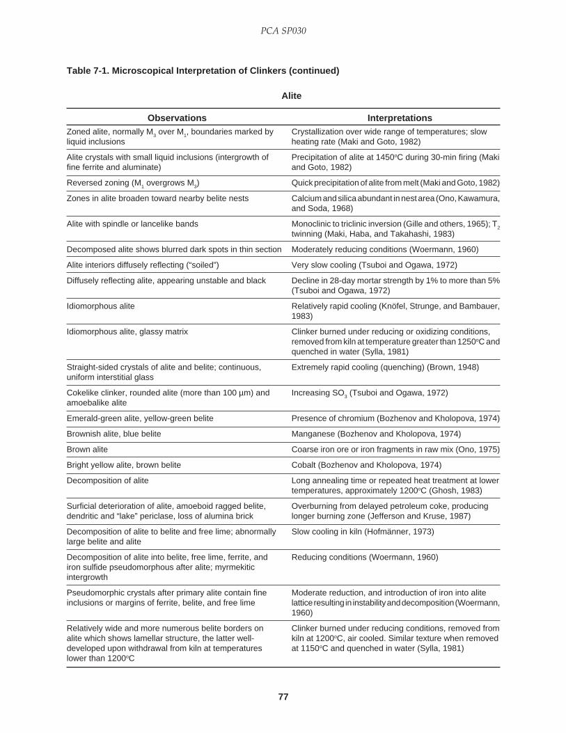
77
PCA SP030
Zoned alite, normally M3 over M1, boundaries marked by Crystallization over wide range of temperatures; slowliquid inclusions heating rate (Maki and Goto, 1982)
Alite crystals with small liquid inclusions (intergrowth of Precipitation of alite at 1450oC during 30-min firing (Makifine ferrite and aluminate) and Goto, 1982)
Reversed zoning (M1 overgrows M3) Quick precipitation of alite from melt (Maki and Goto, 1982)
Zones in alite broaden toward nearby belite nests Calcium and silica abundant in nest area (Ono, Kawamura,and Soda, 1968)
Alite with spindle or lancelike bands Monoclinic to triclinic inversion (Gille and others, 1965); T2
twinning (Maki, Haba, and Takahashi, 1983)
Decomposed alite shows blurred dark spots in thin section Moderately reducing conditions (Woermann, 1960)
Alite interiors diffusely reflecting (“soiled”) Very slow cooling (Tsuboi and Ogawa, 1972)
Diffusely reflecting alite, appearing unstable and black Decline in 28-day mortar strength by 1% to more than 5%(Tsuboi and Ogawa, 1972)
Idiomorphous alite Relatively rapid cooling (Knöfel, Strunge, and Bambauer,1983)
Idiomorphous alite, glassy matrix Clinker burned under reducing or oxidizing conditions,removed from kiln at temperature greater than 1250oC andquenched in water (Sylla, 1981)
Straight-sided crystals of alite and belite; continuous, Extremely rapid cooling (quenching) (Brown, 1948)uniform interstitial glass
Cokelike clinker, rounded alite (more than 100 µm) and Increasing SO3 (Tsuboi and Ogawa, 1972)amoebalike alite
Emerald-green alite, yellow-green belite Presence of chromium (Bozhenov and Kholopova, 1974)
Brownish alite, blue belite Manganese (Bozhenov and Kholopova, 1974)
Brown alite Coarse iron ore or iron fragments in raw mix (Ono, 1975)
Bright yellow alite, brown belite Cobalt (Bozhenov and Kholopova, 1974)
Decomposition of alite Long annealing time or repeated heat treatment at lowertemperatures, approximately 1200oC (Ghosh, 1983)
Surficial deterioration of alite, amoeboid ragged belite, Overburning from delayed petroleum coke, producingdendritic and “lake” periclase, loss of alumina brick longer burning zone (Jefferson and Kruse, 1987)
Decomposition of alite to belite and free lime; abnormally Slow cooling in kiln (Hofmänner, 1973)large belite and alite
Decomposition of alite into belite, free lime, ferrite, and Reducing conditions (Woermann, 1960)iron sulfide pseudomorphous after alite; myrmekiticintergrowth
Pseudomorphic crystals after primary alite contain fine Moderate reduction, and introduction of iron into aliteinclusions or margins of ferrite, belite, and free lime lattice resulting in instability and decomposition (Woermann,
1960)
Relatively wide and more numerous belite borders on Clinker burned under reducing conditions, removed fromalite which shows lamellar structure, the latter well- kiln at 1200oC, air cooled. Similar texture when removeddeveloped upon withdrawal from kiln at temperatures at 1150oC and quenched in water (Sylla, 1981)lower than 1200oC
Table 7-1. Microscopical Interpretation of Clinkers (continued)
Alite
Observations Interpretations

78
Microscopical Examination and Interpretation of Portland Cement and Clinker
Irregular alite with wide border of belite, well-differentiated Clinker burned at 1450°C for 1 hour, cooled to 1200°C inmatrix of large crystals, metallic iron in aluminoferrite kiln (Sylla, 1981)
Decomposition of alite to secondary belite and free lime; Reducing conditions, coarse coal particles falling into rawdecrease in compressive strength; possible abnormal mix (Hawthorne, Richey, and Demoulian, 1981)expansion
Decomposition of alite varied between 10% to 85%; Lab experiment with reducing conditions, slow coolingexceptions in low-Fe or no-Fe clinker (5°C per min, 90 min from 1450°C to 1000°C) (Woermann,
1960)
Intimate mixture of belite and dicalcium ferrite on alite Low temperature re-oxidation (Long, 1982b)lattice planes; free-lime crystals with inclusions of2CaO • Fe
2O
3
Belite fringes on alite (degradation of alite to belite + Maintenance of clinker at 1200°C, and slow cooling offree lime) clinkers with high alumina ratio, accentuated in reducing
environment (Long, 1982b); increased thickening time foroil-well cements (Long, 1984a); and initial viscosityincrease in oil-well cement slurry (Reeves, Bailey, andMcNabb, 1984)
Decomposition of alite to belite and free lime Presence of bivalent iron (Hofmänner, 1973)
Alite decomposition into secondary belite Overburning (Dorn, 1979)
Corroded crystals of alite Slow cooling (Gille and others, 1965)
Belite coating alite Pseudomorphic resorption of alite from lime-poor melt;slow cooling (Gille and others, 1965)
Belitized alite surfaces Slow cooling (Tsuboi and Ogawa, 1972)
Alite decomposed into CaO and C2S; corrosion of alite Tempering (Krämer, 1960)
Serrated alite High Al2O
3/FeO, especially when alkalies are abundant
(Brown, 1948)
Alites greater than 20 µm, with belite fringes Strength decreases about 1% (Tsuboi and Ogawa, 1972)
Mortar strength with average size of alite less than 10 µm Strength decreases usually more than 5% (Tsuboi andOgawa, 1972)
Compressive strength is 10% higher for 20-µm alites 28-day strength variation with alite size (Tsuboi and Ogawa,than 10-µm alites, and 10% lower than 30-µm crystals 1972)
Increase in triclinic alite, increase in gamma belite; Reducing conditions (Uchikawa, 1992)strength not well-developed
Alite with ultra-fine particles under 0.5 µm (inclusions) Excess solid solution (Ono, 1995)
Table 7-1. Microscopical Interpretation of Clinkers (continued)
Alite
Observations Interpretations
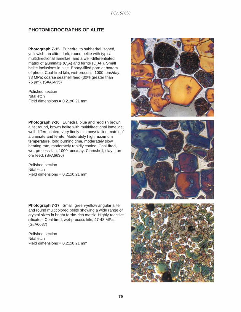
79
PCA SP030
PHOTOMICROGRAPHS OF ALITE
Photograph 7-16 Euhedral blue and reddish brownalite; round, brown belite with multidirectional lamellae;well-differentiated, very finely microcrystalline matrix ofaluminate and ferrite. Moderately high maximumtemperature, long burning time, moderately slowheating rate, moderately rapidly cooled. Coal-fired,wet-process kiln, 1000 tons/day. Clamshell, clay, iron-ore feed. (S#A6636)
Polished sectionNital etchField dimensions = 0.21x0.21 mm
Photograph 7-17 Small, green-yellow angular aliteand round multicolored belite showing a wide range ofcrystal sizes in bright ferrite-rich matrix. Highly reactivesilicates. Coal-fired, wet-process kiln, 47-48 MPa.(S#A6637)
Polished sectionNital etchField dimensions = 0.21x0.21 mm
Photograph 7-15 Euhedral to subhedral, zoned,yellowish tan alite; dark, round belite with typicalmultidirectional lamellae; and a well-differentiatedmatrix of aluminate (C
3A) and ferrite (C
4AF). Small
belite inclusions in alite. Epoxy-filled pore at bottomof photo. Coal-fired kiln, wet-process, 1000 tons/day,38 MPa; coarse seashell feed (30% greater than75 µm). (S#A6635)
Polished sectionNital etchField dimensions = 0.21x0.21 mm

80
Microscopical Examination and Interpretation of Portland Cement and Clinker
PHOTOMICROGRAPHS OF ALITE (CONTINUED)
Photograph 7-18 Clinker thin section (approximately15 µm thick) showing relatively large angular alite;smaller, round belite; and normal ferrite with its shortslender intersecting crystals, between which thealuminate occurs (not visible at this magnification).(S#A6638)
Transmitted, plane-polarized lightField dimensions = 0.21x0.21 mm
Photograph 7-19 Same field of view as previousphotograph except in partially crossed polars. Variousinterference colors due, in large part, to differentcrystallographic orientations. (S#A6639)
Photograph 7-20 Same field as previous photographbut with reflected light and nital etch. Euhedral, brownalite; round belite with multidirectional lamellae; well-differentiated matrix (almost invisible in thephotograph). High maximum temperature, longburning time, slow heating rate, quickly cooled. Coal-fired, dry-process kiln, 2000 tons/day. (S#A6640)

81
PCA SP030
PHOTOMICROGRAPHS OF ALITE (CONTINUED)
Photograph 7-21 Blue, subhedral alite crystals withvery narrow belite fringe (almost the only belite in theclinker) and matrix of gray aluminate and dull ferrite.Average alite size is approximately 26 µm. Coal-fired,dry-process kiln, 550 tons/day. (S#A6641)
Polished sectionNital etchField dimensions = 0.12x0.12 mm
Photograph 7-22 Stacked, blue, cannibalistic,strongly zoned euhedral alite with abundant inclusions.Small, round belite crystals; well-differentiated matrix.Belite coating on alite. High maximum temperature,long burning time, slow heating rate, slowly cooled,35 MPa. Coal-fired, wet-process kiln. (S#A6642)
Polished sectionNital etchField dimensions = 0.21x0.21 mm
Photograph 7-23 Marked topographic reliefaccentuating silicate crystal internal structures.Produced by 10-second nital etch followed by 10-second polish on Texmet™ with 0.05-µm alumina.(S#A6643)
Polished sectionField dimensions = 0.14x0.14 mm

82
Microscopical Examination and Interpretation of Portland Cement and Clinker
PHOTOMICROGRAPHS OF ALITE (CONTINUED)
Photograph 7-24 Coarsely crystalline silicates fromcoarse seashell feed. Angular, strongly zoned alite andround, relatively small belite with coarse lamellae.Coal- and coke-fired, semidry process kiln, 1850 tons/day. High maximum temperature, long burning time,slow heating rate, quick to moderately quick cooling,44 MPa. (S#A6644)
Polished sectionNital etchField dimensions = 0.21x0.21 mm

83
PCA SP030
Large proportion of belite Low lime saturation factor (Long, 1982a; Fundal, 1980)
Equal alite and belite Lime saturation factor = approximately 88% (Fundal, 1980)
Belite agglomerations: Classification of belite agglomerations (Hofmänner, 1973)(a) Sharply outlined clusters(b) Diffuse limited clusters(c) Streaks(d) Spots
Belite nests Ash shortage, excessive quartz grain size, presence offeldspar and blast furnace slag (Gille and others, 1965)
Nests of belite Inadequately mixed raw material, decline of mortar strength(Tsuboi and Ogawa, 1972)
Nests of belite Vestigal quartz grain (Krämer, 1960)
Round, compact belite nests of large, polygonal, well- Large quartz or flint, +44 µm (Fundal, 1980)lamellated crystals
Pore-centered belite nests with relatively large, densely Coarse quartz in feed (Long, 1982a)packed crystals, producing large alite at highertemperature if lime is available
Belite nests, possibly with central pore Low lime inclusions such as quartz splinters, ash droplets(Gille and others, 1965)
Glass core in belite nest, large alite adjacent to belite nest Residual SiO2, a frequent component of insoluble residues(Fundal, 1980)
Glass C2S in center of belite nests Quartz grains are large or poorly burned (Tsuboi andOgawa, 1972)
Closely spaced belite Large quartz grains in raw mix (Tsuboi and Ogawa, 1972)
Tight belite crystals in nests with sparse liquid phase Coarse quartz (Miller, 1981; Gille and others, 1965)
Large belite clusters Unstable ring formation, especially in sulfate-rich clinkers,if no large quartz grains in raw mix (Fundal, 1980);segregation of raw mix (DeLisle, 1979); poor strengthdevelopment in oil-well cements (Reeves, Bailey, andMcNabb, 1984)
Large clusters of belite associated with high contents of High lime saturation factor (Fundal, 1980)free lime
Large patches of belite; belite nests from coarse quartz Selective reaction of raw mix components: clay at lowertemperature than that for quartz, muscovite, hornblende,and Ca-feldspars resulting in early nodulation(micronodules) and clinker dust with high lime saturationfactor (Fundal, 1980)
Subhedral, pseudohexagonal, lath shaped alite and Coal ash absorption (Rao and others, 1993)belite clusters (subround), some hexagonal belite
Rounded belite in dense nests Intense burning (Tsuboi and Ogawa, 1972)
Belite nests with curved boundaries and very little Concentration of siliceous component (lack of lime)liquid phase (Hofmänner, 1973)
Large number of belite clusters Decrease in grindability (Dorn, 1985)
Peripheral annular region of belite and flux-rich material Late deposition of coal-ash layers (Long, 1982)in clinker nodule
Table 7-1. Microscopical Interpretation of Clinkers (continued)
Belite
Observations Interpretations
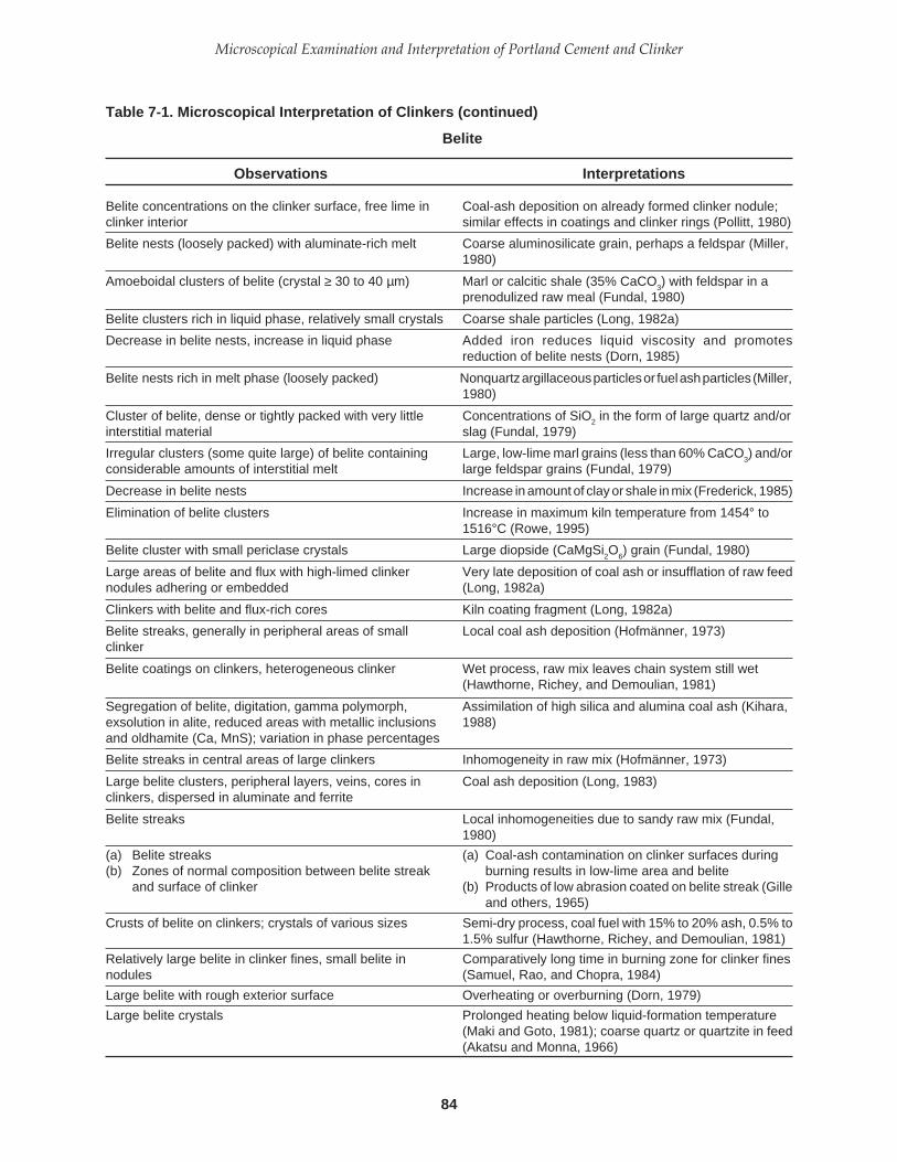
84
Microscopical Examination and Interpretation of Portland Cement and Clinker
Belite concentrations on the clinker surface, free lime in Coal-ash deposition on already formed clinker nodule;clinker interior similar effects in coatings and clinker rings (Pollitt, 1980)
Belite nests (loosely packed) with aluminate-rich melt Coarse aluminosilicate grain, perhaps a feldspar (Miller,1980)
Amoeboidal clusters of belite (crystal ≥ 30 to 40 µm) Marl or calcitic shale (35% CaCO3) with feldspar in a
prenodulized raw meal (Fundal, 1980)
Belite clusters rich in liquid phase, relatively small crystals Coarse shale particles (Long, 1982a)
Decrease in belite nests, increase in liquid phase Added iron reduces liquid viscosity and promotesreduction of belite nests (Dorn, 1985)
Belite nests rich in melt phase (loosely packed) Nonquartz argillaceous particles or fuel ash particles (Miller,1980)
Cluster of belite, dense or tightly packed with very little Concentrations of SiO2 in the form of large quartz and/orinterstitial material slag (Fundal, 1979)
Irregular clusters (some quite large) of belite containing Large, low-lime marl grains (less than 60% CaCO3) and/or
considerable amounts of interstitial melt large feldspar grains (Fundal, 1979)
Decrease in belite nests Increase in amount of clay or shale in mix (Frederick, 1985)
Elimination of belite clusters Increase in maximum kiln temperature from 1454° to1516°C (Rowe, 1995)
Belite cluster with small periclase crystals Large diopside (CaMgSi2O
6) grain (Fundal, 1980)
Large areas of belite and flux with high-limed clinker Very late deposition of coal ash or insufflation of raw feednodules adhering or embedded (Long, 1982a)
Clinkers with belite and flux-rich cores Kiln coating fragment (Long, 1982a)
Belite streaks, generally in peripheral areas of small Local coal ash deposition (Hofmänner, 1973)clinker
Belite coatings on clinkers, heterogeneous clinker Wet process, raw mix leaves chain system still wet(Hawthorne, Richey, and Demoulian, 1981)
Segregation of belite, digitation, gamma polymorph, Assimilation of high silica and alumina coal ash (Kihara,exsolution in alite, reduced areas with metallic inclusions 1988)and oldhamite (Ca, MnS); variation in phase percentages
Belite streaks in central areas of large clinkers Inhomogeneity in raw mix (Hofmänner, 1973)
Large belite clusters, peripheral layers, veins, cores in Coal ash deposition (Long, 1983)clinkers, dispersed in aluminate and ferrite
Belite streaks Local inhomogeneities due to sandy raw mix (Fundal,1980)
(a) Belite streaks (a) Coal-ash contamination on clinker surfaces during(b) Zones of normal composition between belite streak burning results in low-lime area and belite
and surface of clinker (b) Products of low abrasion coated on belite streak (Gilleand others, 1965)
Crusts of belite on clinkers; crystals of various sizes Semi-dry process, coal fuel with 15% to 20% ash, 0.5% to1.5% sulfur (Hawthorne, Richey, and Demoulian, 1981)
Relatively large belite in clinker fines, small belite in Comparatively long time in burning zone for clinker finesnodules (Samuel, Rao, and Chopra, 1984)
Large belite with rough exterior surface Overheating or overburning (Dorn, 1979)
Large belite crystals Prolonged heating below liquid-formation temperature(Maki and Goto, 1981); coarse quartz or quartzite in feed(Akatsu and Monna, 1966)
Table 7-1. Microscopical Interpretation of Clinkers (continued)
Belite
Observations Interpretations

85
PCA SP030
Belite size increasing, belite abundance decreasing Increasing burning temperature from 1500°C to 1700°C(Suzukawa, Kono, and Fukunaga, 1964)
Coarsening of belite, aluminate, and aluminoferrite; Clinker burned under oxidizing conditions, cooled toirregular belite outline, idiomorphous alite temperatures below 1250oC in the kiln (Sylla, 1981)
Relatively large belite inclusions in alite, large belite Abundance of coarse quartz in feed; belite and alitecrystals (45 µm) became much smaller upon use of finely ground friable
silica (Dorn, 1980)
Large, irregularly shaped belite Very slow cooling (Ono, Kawamura, and Soda, 1968)
Belite is 1-4-µm diameter at 1300°C but grows to Recrystallization during burning at high temperature (Ono,20-40 µm crystals Kawamura, and Soda, 1968)
Multidirectional lamellar structure of belite Formed and coarsened during alpha to alpha primetransition during cooling (Hofmänner, 1973); clinker burnedat greater than 1420oC (Ono, 1975)
Increase in proportion of cross laminations in belite Increase in TiO2 content in clinker (Knöfel, 1977)
crystals
Amber belite with Type I microstructure Belite kept at “alpha temperature” in kiln coating (Ono,(multidirectional lamellae) 1981)
Small, round Type II belite Low burning temperature (Ono, Kawamura, and Soda,1968)
Sharp, wide lamellae Distorted beta belite, raw mix rich in Fe2O
3 and alkalies
(Gouda, 1980)
Colorless Type II belite (parallel striations) Belite held at “alpha-prime temperature” in kiln coating(Ono, 1981); burning below 1420°C (Ono, 1975)
Rounded belite without lamellae, finely intergrown Rapidly cooled clinker (Gille and others, 1965)groundmass
Belite crystals with no stripes, commonly with rents Stress during rapid quenching (Gille and others, 1965)and cracks
Nontwinned belite SO3 more than 1% (Tsuboi and Ogawa, 1972)
Structureless belite crystals (uniform reflection) Extremely rapid quenching, as in lab (Gille and others,1965)
Polysynthetic twinning in belite Formed during very slow cooling as a result of alpha primeto beta transition (Hofmänner, 1973)
Belite with polysynthetic twinning Normal cooling rate (Krämer, 1960)
Ragged belite with dotlike inclusions Clinker burned with long flame (Ono, 1981)
Ragged crystals of belite Very slow cooling (Krämer, 1960)
Ragged belite with no degradation of alite Slow cooling at certain alumina to iron ratios; also affected byalkali content (Long, 1984, unpublished ICMA presentation)
Ragged belite Alpha to alpha prime inversion in contact with melt andslow cooling (Ono, 1981)
Ragged belite Slow cooling and resolution (Gille and others, 1965;Midgley, in Taylor, 1964; DeLisle, 1976, 1979)
Belite with lamellar extensions, surficial deterioration of Slow in-kiln cooling due to excessive insufflationalite to belite, relatively coarse crystalline matrix (Hoodmaker and Franklin, 1995)
Belite overgrowths Slow cooling (Gille and others, 1965); very slow cooling(Lee, 1982)
Table 7-1. Microscopical Interpretation of Clinkers (continued)
Belite
Observations Interpretations

86
Microscopical Examination and Interpretation of Portland Cement and Clinker
Rough belite surface, prominent lamellae, segmented Reducing conditions (Dorn, 1979)fingerlike sections
Secondary belite, free lime corrosion of alite Slow cooling (Gille and others, 1965)
Erosion of alite crystals to intimate mixture of belite and Slow cooling, temperature at approximately 1200°C for anfree lime pseudomorphic after alite appreciable time (Long, 1983)
Erosion of alite crystals to form surface belite; pinhead Slow cooling; alumina ratio above 2.5; up tobelite in matrix 10% reduction in 28-day strength (Long, 1983)
Droplike belite in liquid phase; commonly associated with Excess SiO2 (Hofmänner, 1973)
dendritic periclase
Secondary belite, free lime, periclase; autoclave problems Failure of solid fuels (fly ash, carbonaceous shales, coaltailings as part of raw mix) to burn before granulation zone(Hawthorne, Richey, and Demoulian, 1981)
Secondary belite in the matrix Slow cooling in the temperature range > 1300°C (Scheubel,1987)
Secondary belite coating on alite Resorption into liquid phase (Hofmänner, 1973); slowcooling (Midgley, in Taylor, 1964)
Myrmekitical intergrowth of belite in alite, Decomposition via slow cooling; sometimes acceleratedpseudomorphous free lime, and remnants of by foreign ions, excess alkalies, embedded Fe++, andnondecomposed alite moderate reducing conditions (Gille and others, 1965)
Belite grains with distinct fissility planes Gamma belite and reducing conditions (Rajczyk, 1990)
Belite laminae on rhombic alite planes, usually three Reducing conditions in sinter zone (Gille and others,groups intersecting 1965)
Tiny belite inclusions suggestive of lamellae in alite Deficient air supply in sintering zone (Gille and others,1965)
Dismembered, finely dendritic crystals of belite Excess crystallization of belite (Gille and others, 1965)
Belite next to free lime in normally burned clinker Alkali belite (Gille and others, 1965; DeLisle, 1976)
Irregular belite Overburning (Prout, 1979)
Overlapping belite Too much MgO, ZnO, and others that lower viscosity(Tsuboi and Ogawa, 1972)
Wide lamellae on belite, corroded alite, and cooling cracks Alkali in clinker (Gille and others, 1965)
Large belite crystals, colorless, low birefringence Alkali belite (Ono, letter, 1977)(0.012-0.015), sharp striations, coarse sandwich structureof alpha and beta seen under crossed nicols, crystalsurface free from iron phase
Clear belite ring Alpha belite, alkali-rich, derived from melted feldspar whichreacted with f-CaO (Ono, 1981)
Dendritic belite High alkali (K-feldspar) in raw mix (Gille and others, 1965);Low primary air volume or pressure, excessive burning-zone temperature, slow cooling rate, high MgO level—approximately 4.5% (Dorn, personal communication, 1985)
Increase in amount of alite, crystals with higher aspect Fluorine in the presence of SO3 in raw mix (Wei andratio and smaller size, decrease in belite percentage, Mingfen, 1988)becoming brain, finger, or leaflike
Alite containing K+ may tend to decompose Above a certain potassium percentage alite does not form,but instead belite and free lime (Woermann, 1960)
Clear belite crystals Quick cooling, no exsolution of impurities (Ono, 1975)
Table 7-1. Microscopical Interpretation of Clinkers (continued)
Belite
Observations Interpretations
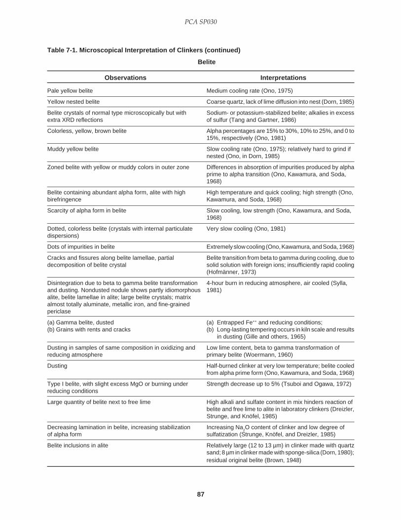
87
PCA SP030
Pale yellow belite Medium cooling rate (Ono, 1975)
Yellow nested belite Coarse quartz, lack of lime diffusion into nest (Dorn, 1985)
Belite crystals of normal type microscopically but with Sodium- or potassium-stabilized belite; alkalies in excessextra XRD reflections of sulfur (Tang and Gartner, 1986)
Colorless, yellow, brown belite Alpha percentages are 15% to 30%, 10% to 25%, and 0 to15%, respectively (Ono, 1981)
Muddy yellow belite Slow cooling rate (Ono, 1975); relatively hard to grind ifnested (Ono, in Dorn, 1985)
Zoned belite with yellow or muddy colors in outer zone Differences in absorption of impurities produced by alphaprime to alpha transition (Ono, Kawamura, and Soda,1968)
Belite containing abundant alpha form, alite with high High temperature and quick cooling; high strength (Ono,birefringence Kawamura, and Soda, 1968)
Scarcity of alpha form in belite Slow cooling, low strength (Ono, Kawamura, and Soda,1968)
Dotted, colorless belite (crystals with internal particulate Very slow cooling (Ono, 1981)dispersions)
Dots of impurities in belite Extremely slow cooling (Ono, Kawamura, and Soda, 1968)
Cracks and fissures along belite lamellae, partial Belite transition from beta to gamma during cooling, due todecomposition of belite crystal solid solution with foreign ions; insufficiently rapid cooling
(Hofmänner, 1973)
Disintegration due to beta to gamma belite transformation 4-hour burn in reducing atmosphere, air cooled (Sylla,and dusting. Nondusted nodule shows partly idiomorphous 1981)alite, belite lamellae in alite; large belite crystals; matrixalmost totally aluminate, metallic iron, and fine-grainedpericlase
(a) Gamma belite, dusted (a) Entrapped Fe++ and reducing conditions;(b) Grains with rents and cracks (b) Long-lasting tempering occurs in kiln scale and results
in dusting (Gille and others, 1965)
Dusting in samples of same composition in oxidizing and Low lime content, beta to gamma transformation ofreducing atmosphere primary belite (Woermann, 1960)
Dusting Half-burned clinker at very low temperature; belite cooledfrom alpha prime form (Ono, Kawamura, and Soda, 1968)
Type I belite, with slight excess MgO or burning under Strength decrease up to 5% (Tsuboi and Ogawa, 1972)reducing conditions
Large quantity of belite next to free lime High alkali and sulfate content in mix hinders reaction ofbelite and free lime to alite in laboratory clinkers (Dreizler,Strunge, and Knöfel, 1985)
Decreasing lamination in belite, increasing stabilization Increasing Na2O content of clinker and low degree of
of alpha form sulfatization (Strunge, Knöfel, and Dreizler, 1985)
Belite inclusions in alite Relatively large (12 to 13 µm) in clinker made with quartzsand; 8 µm in clinker made with sponge-silica (Dorn, 1980);residual original belite (Brown, 1948)
Table 7-1. Microscopical Interpretation of Clinkers (continued)
Belite
Observations Interpretations

88
Microscopical Examination and Interpretation of Portland Cement and Clinker
PHOTOMICROGRAPHS OF BELITE
Photograph 7-25 Experimental laboratory burn withraw mix containing marl instead of quartz as a silicasource. Resulting belite was well scattered in clinkerand, to a minor extent, as nests. 1000oC for 30 min,1425oC for 10 min. Very rapid temperature change.Average alite size = 20 µm. Clinker courtesy of JoeGarcia, Capitol Cement, San Antonio, Texas.(S#A6645)
Polished sectionNital etchField dimensions = 0.53x0.53 mm
Photograph 7-26 Experimental laboratory burn withraw mix containing quartz (44-75 µm) as a silicasource. Average alite crystal size = 44 µm. 1000oC for30 min, 1425oC for 10 min. Very rapid temperaturechange. Note abundant free lime inclusions in alite.Clinker courtesy of Joe Garcia, Capitol Cement, SanAntonio, Texas. (S#A6646)
Thin sectionTransmitted, plane-polarized lightField dimensions = 0.21x0.21 mm
Photograph 7-27 Ragged belite crystals and belitecoating on alite, one of which is twinned. Noteabundant dotlike impurities in alite. Coarsely crystallinematrix with gray aluminate and relatively bright ferrite.Slowly cooled clinker. (S#A6647)
Polished sectionNital on KOH etchField dimensions = 0.21x0.21 mm

89
PCA SP030
PHOTOMICROGRAPHS OF BELITE (CONTINUED)
Photograph 7-28 Polished section of cementcentrifuged in low-viscosity epoxy to produce a particlesize and density gradation. Arrow on coarse particlenear the base of the test tube (left) indicates alkalisulfate. Arrow on fine particle near the top of thecement (right) indicates gypsum. See Campbell(1986). (S#A6648)
Reflected lightField dimensions = 0.21x0.21 mm
Photograph 7-29 Zoned euhedral to subhedral alite;ragged, round, internally disorganized belite; well-differentiated matrix; and round pore (upper center)with peripheral alkali sulfate. Coal- and coke-fired, dry-process kiln, 900 tons/day. High maximumtemperature, moderately long burning time, slowheating rate, slow to moderately slow cooling rate.(S#A6649)
Polished sectionNital etchField dimensions = 0.21x0.21 mm
Photograph 7-30 Ragged belite from very slowcooling. Extension of “fingers” into matrix. Note dotlikeimpurities. Kiln coating. Coal-fired, dry-process kiln,2350 tons/day. (S#A6650)
Thin sectionTransmitted, plane-polarized lightField dimensions = 0.21x0.21 mm

90
Microscopical Examination and Interpretation of Portland Cement and Clinker
PHOTOMICROGRAPHS OF BELITE (CONTINUED)
Photograph 7-32 Same clinker sample as above butdifferent nodule, showing relatively small, irregular,brown belite wrapping around blue alite crystals,thought to be typical for clinkers burned at a hightemperature for a long time. (S#A6652)
Polished sectionKOH followed by nital etchField dimensions = 0.21x0.21 mm
Photograph 7-31 Same field of view as previousphotograph, but with partially crossed polars, showinghighly birefringent and strongly pleochroic ferrite.(S#A6651)
Photograph 7-33 Irregular to normally round, brownbelite; subhedral, angular, blue alite with cleavagecracks; and matrix of finely microcrystalline aluminate(C
3A) and lath-form ferrite. High maximum
temperature, long burning time, slow heating rate,quick cooling, 41-42 MPa. Coal-fired, dry-process kiln,2750 tons/day. (S#A6653)
Polished sectionNital etchField dimensions = 0.21x0.21 mm

91
PCA SP030
PHOTOMICROGRAPHS OF BELITE (CONTINUED)
Photograph 7-34 Belite crystals comprising sharplydelineated nest around pore (black), probably the siteof a coarse quartz grain in the feed. Coal- and coke-fired, dry-process kiln. (S#A6654)
Thin sectionField dimensions = 0.53x0.53 mm
Photograph 7-35 Clear belite ring around centralpore formed by silica mobilization during sintering ofcoarse quartz in feed. (S#A6655)
Thin sectionThickness = approximately 20 µmField dimensions = 0.53x0.53 mm
Photograph 7-36 Tightly packed clear belite nestfrom coarse quartz in raw feed. Crystals exhibit widerange of interference colors due to differentcrystallographic orientations. Note also the generallymottled pattern within individual crystals, suggesting asomewhat disorganized lamellar structure. (S#A6656)
Thin sectionCrossed polarsField dimensions = 0.60x0.60 mm
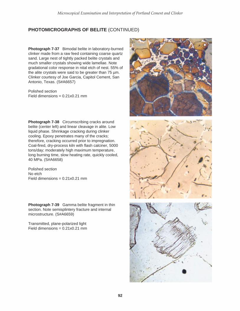
92
Microscopical Examination and Interpretation of Portland Cement and Clinker
PHOTOMICROGRAPHS OF BELITE (CONTINUED)
Photograph 7-37 Bimodal belite in laboratory-burnedclinker made from a raw feed containing coarse quartzsand. Large nest of tightly packed belite crystals andmuch smaller crystals showing wide lamellae. Notegradational color response in nital etch of nest. 55% ofthe alite crystals were said to be greater than 75 µm.Clinker courtesy of Joe Garcia, Capitol Cement, SanAntonio, Texas. (S#A6657)
Polished sectionField dimensions = 0.21x0.21 mm
Photograph 7-38 Circumscribing cracks aroundbelite (center left) and linear cleavage in alite. Lowliquid phase. Shrinkage cracking during clinkercooling. Epoxy penetrates many of the cracks;therefore, cracking occurred prior to impregnation.Coal-fired, dry-process kiln with flash calciner, 5000tons/day; moderately high maximum temperature,long burning time, slow heating rate, quickly cooled,40 MPa. (S#A6658)
Polished sectionNo etchField dimensions = 0.21x0.21 mm
Photograph 7-39 Gamma belite fragment in thinsection. Note semisplintery fracture and internalmicrostructure. (S#A6659)
Transmitted, plane-polarized lightField dimensions = 0.21x0.21 mm
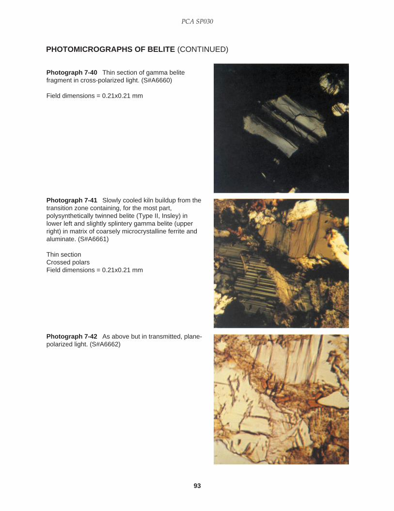
93
PCA SP030
PHOTOMICROGRAPHS OF BELITE (CONTINUED)
Photograph 7-40 Thin section of gamma belitefragment in cross-polarized light. (S#A6660)
Field dimensions = 0.21x0.21 mm
Photograph 7-41 Slowly cooled kiln buildup from thetransition zone containing, for the most part,polysynthetically twinned belite (Type II, Insley) inlower left and slightly splintery gamma belite (upperright) in matrix of coarsely microcrystalline ferrite andaluminate. (S#A6661)
Thin sectionCrossed polarsField dimensions = 0.21x0.21 mm
Photograph 7-42 As above but in transmitted, plane-polarized light. (S#A6662)

94
Microscopical Examination and Interpretation of Portland Cement and Clinker
PHOTOMICROGRAPHS OF BELITE (CONTINUED)
Photograph 7-43 Dark blue belite (Type II, Insley) atupper right, subhedral to anhedral alite (pale blue),and pink periclase (center left). Coarsely crystallinematrix. Coal- and coke-fired kiln, wet process, 950tons/day. Moderately long burning rate, slow heatingrate, moderately slow cooling rate. (S#A6663)
Polished sectionNital etchField dimensions = 0.21x0.21 mm
Photograph 7-44 Polysynthetically twinned belite(Type II, Insley) in slowly cooled kiln buildup.(S#A6664)
Polished sectionNital etchField dimensions = 0.14x0.14 mm
Photograph 7-45 Blue, amoeboid belite in a coarselycrystalline, matrix-rich clinker. Amoeboid belite crystalsseem to be most common in clinkers burned at a hightemperature. Angular, tan alite. Other clinkers in thissection contained alite that produced a blue color.(S#A6665)
Polished sectionNital etchField dimensions = 0.14x0.14 mm

95
PCA SP030
PHOTOMICROGRAPHS OF BELITE (CONTINUED)
Photograph 7-46 Polished section of coarselycrystalline clinker. Belite crystals exhibit relatively largeareas which are either nonlamellar or show a singleset of parallel lamellae. Type I belite (Insley)dominates clinker. KOH extraction of matrix andconcentration of silicates, followed by XRD analysisindicating 7% to 10% of the belite comprised of alphaform. Brightly reflecting ferrite. Wet-process kiln, 1000tons/day. High maximum temperature, long burningtime, slow heating rate, moderately quick cooling.(S#A6666)
Nital etchField dimensions = 0.21x0.21 mm
Photograph 7-47 Very coarse, yellow-brownlamellae in belite grain (lower center), perhaps residualfrom an earlier polymorph. Coal-fired kiln, wet process.High maximum temperature, long burning time, slowheating rate, quickly cooled, 42 MPa. (S#A6667)
Polished sectionNital etchField dimensions = 0.13x0.13 mm
Photograph 7-48 Round belite crystals (brown)showing minimal development of lamellae. Coarsefeed. Low maximum temperature, moderately longburning time, slow heating rate, moderately slowcooling rate. Dry-process kiln, gas fired, 3000 tons/day. (S#A6668)
Polished sectionNital etchField dimensions = 0.38x0.38 mm
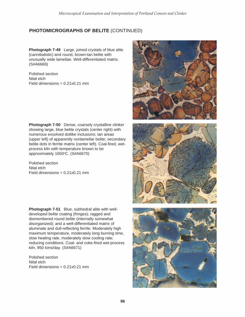
96
Microscopical Examination and Interpretation of Portland Cement and Clinker
PHOTOMICROGRAPHS OF BELITE (CONTINUED)
Photograph 7-49 Large, joined crystals of blue alite(cannibalistic) and round, brown-tan belite withunusually wide lamellae. Well-differentiated matrix.(S#A6669)
Polished sectionNital etchField dimensions = 0.21x0.21 mm
Photograph 7-50 Dense, coarsely crystalline clinkershowing large, blue belite crystals (center right) withnumerous exsolved dotlike inclusions; tan areas(upper left) of apparently nonlamellar belite; secondarybelite dots in ferrite matrix (center left). Coal-fired, wet-process kiln with temperature known to beapproximately 1650oC. (S#A6670)
Polished sectionNital etchField dimensions = 0.21x0.21 mm
Photograph 7-51 Blue, subhedral alite with well-developed belite coating (fringes); ragged anddismembered round belite (internally somewhatdisorganized); and a well-differentiated matrix ofaluminate and dull-reflecting ferrite. Moderately highmaximum temperature, moderately long burning time,slow heating rate, moderately slow cooling rate;reducing conditions. Coal- and coke-fired wet-processkiln, 950 tons/day. (S#A6671)
Polished sectionNital etchField dimensions = 0.21x0.21 mm

97
PCA SP030
PHOTOMICROGRAPHS OF BELITE (CONTINUED)
Photograph 7-52 Dismembered and dendritic belite,ordinary round belite, and belite coatings on alite.Coarsely crystalline matrix. Gas- and coal-fired clinkerfrom wet-process kiln, 500 tons/day. High maximumtemperature, long burning time, slow heating rate, slowcooling. (S#A6672)
Polished sectionNital etchField dimensions = 0.21x0.21 mm
Photograph 7-53 Dendritic belite in ferrite-rich matrixof clinker containing fragments of refractory brick (notshown). Brightly reflecting ferrite in plane-polarizedlight is unusually pleochroic, suggesting compositionalchange from refractory brick consumption. (S#A6673)
Polished sectionNital etchField dimensions = 0.14x0.14 mm
Photograph 7-54 Dendritic belite in coarselycrystalline clinker. Raw feed has almost 38% greaterthan 45 µm. Moderately high temperature, longburning time, slow heating rate, and quick cooling rate.Coal-fired wet-process kiln; 960 tons/day. (S#A6674)
Polished sectionNital etchField dimensions = 0.21x0.21 mm
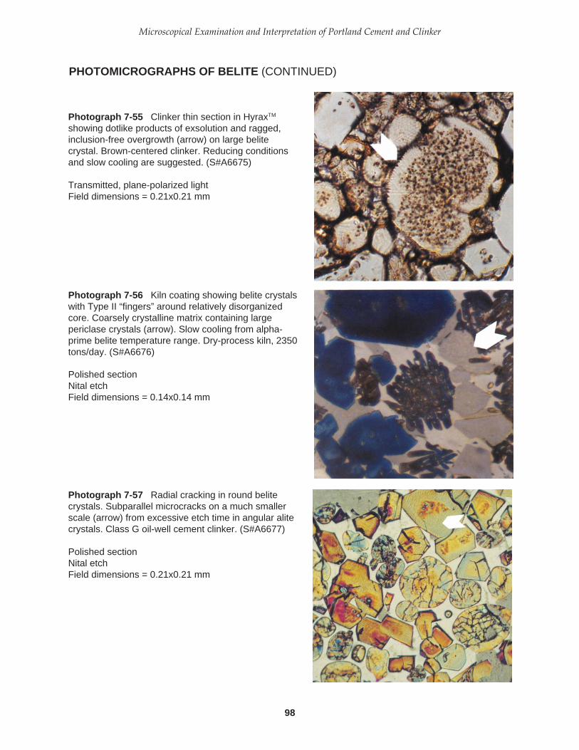
98
Microscopical Examination and Interpretation of Portland Cement and Clinker
PHOTOMICROGRAPHS OF BELITE (CONTINUED)
Photograph 7-55 Clinker thin section in HyraxTM
showing dotlike products of exsolution and ragged,inclusion-free overgrowth (arrow) on large belitecrystal. Brown-centered clinker. Reducing conditionsand slow cooling are suggested. (S#A6675)
Transmitted, plane-polarized lightField dimensions = 0.21x0.21 mm
Photograph 7-56 Kiln coating showing belite crystalswith Type II “fingers” around relatively disorganizedcore. Coarsely crystalline matrix containing largepericlase crystals (arrow). Slow cooling from alpha-prime belite temperature range. Dry-process kiln, 2350tons/day. (S#A6676)
Polished sectionNital etchField dimensions = 0.14x0.14 mm
Photograph 7-57 Radial cracking in round belitecrystals. Subparallel microcracks on a much smallerscale (arrow) from excessive etch time in angular alitecrystals. Class G oil-well cement clinker. (S#A6677)
Polished sectionNital etchField dimensions = 0.21x0.21 mm

99
PCA SP030
PHOTOMICROGRAPHS OF BELITE (CONTINUED)
Photograph 7-58 Belite striations in light blue alite.Multicolored, round belite showing typical lamellae, butsomewhat scalloped cross section. Small secondarybelite in brightly reflecting ferrite matrix. Clinker samplecontains remnants of chrome-magnesia refractorybrick. (S#A6678)
Polished sectionNital etchField dimensions = 0.21x0.21 mm
Photograph 7-59 Alite crystals with secondary belitestriations (arrow) and belite fringes. Coarselycrystalline matrix of aluminate and dull ferrite. Slowcooling and reducing conditions. (S#A6679)
Polished sectionNital etchField dimensions = 0.21x0.21 mm
Photograph 7-60 Coarsely crystalline silicates fromcoarse seashell feed. Pale olive to tan, angular alitecrystals with belite striations (arrow); round, coarselylamellar belite; and a finely microcrystalline matrix ofaluminate and dull ferrite. High maximum temperature,long burning time, slow heating rate, quick tomoderately quick cooling, 44 MPa. Coal- and coke-fired, semidry-process kiln, 1850 tons/day. (S#A6680)
Polished sectionNital etchField dimensions = 0.21x0.21 mm

100
Microscopical Examination and Interpretation of Portland Cement and Clinker
PHOTOMICROGRAPHS OF BELITE (CONTINUED)
Photograph 7-61 Green belite nest in center ofbroken clinker. Energy dispersive X-ray analysis(EDXA) indicates calcium, silicon, potassium, andtraces of chromium, magnesium, aluminum, sulfur,chlorine, and iron. (S#A6681)
Reflected light, stereomicroscopeField dimensions = 1.25x1.25 mm
Photograph 7-62 Crushed clinkers with yellowishbrown centers, produced in a kiln with a reducingenvironment. Examination at high magnificationreveals belite coatings on alite, dull ferrite reflectivity,and alkali aluminate. (S#A6682)
Polished sectionNo etchField dimensions = 1.2x1.2 mm
Photograph 7-63 Photomicrograph of clinker particlein a Class H oil-well cement, showing recrystallizedbelite classified by the writer as Type B. Note the finelymicrocrystalline interior of the crystal and near-totalloss of lamellar structure. Lamellar extensions are nota criterion of this belite designation. Possibleinterpretations of Type B are slow cooling, reducingconditions, or both. (S#67842)
Polished sectionNital etchField dimensions = 0.20x0.20 mm

101
PCA SP030
PHOTOMICROGRAPHS OF BELITE (CONTINUED)
Photograph 7-64 Type C belite showing alterationonly visible in the outer regions of the grain where theoriginal lamellae have been recrystallized into a finelymicrocrystalline mosaic. Class H oil-well cement.(S#67843)
Polished sectionNital etchField dimensions = 0.12x0.12 mm

102
Microscopical Examination and Interpretation of Portland Cement and Clinker
Abundant aluminate High Al2O3 to Fe2O3 ratio, alumina ratio (Gille and others, 1965)
Abundant aluminate, abundant ferrite Low Al2O
3 to Fe
2O
3 ratio, less than 0.7 (Gille and others,
1965)
Plenty of liquid phase Silica ratio (SR) low (Hofmänner, 1973)
Aluminate greatly dominates liquid phase High alumina ratio (Long, 1982a); strong reducingconditions (Dorn, personal communication, 1985)
Aluminate greater than ferrite Alumina ratio high (Hofmänner, 1973)
Ferrite greater than aluminate Alumina ratio low (Hofmänner, 1973)
Large quantity of liquid phase, high ferrite content Low silica ratio and alumina ratio (Long, 1982a)
Great relative increase in aluminate content Cooling under reducing conditions and temperature rangebetween 1000oC and 1200oC (Sylla, 1981)
Small quantity of liquid phase, dusty fine clinker High silica ratio (Long, 1984b)
Low quantity of melt phases High silica modulus (Miller, 1980); silica ratio too high(Hofmänner, 1973)
Differentiation of interstitial aluminate and ferrite; alite Equilibrium cooling to complete crystallization throughand belite lose sharp regularity 1250oC (Brown, 1948)
(a) Groundmass structure of large crystals (a) Extended conditions for development(b) Tight, interlaced structure of small crystals (b) Quenching (Gille and others, 1965)
Coarse structure of aluminate and ferrite; belite fringes Very slow cooling (Long, 1982a)on alite
Large separated ferrite and aluminate crystals Reducing conditions (Brugan, 1979)surrounded with normal matrix; brown areas in clinkers
Coarsening of aluminate crystals, aluminoferrite, and belite; Clinker burned under reducing conditions, removed fromincrease in aluminate at expense of aluminoferrite kiln at temperature less than 1250°C, slow cooling under
reducing conditions (Sylla, 1981)
Aluminate growth at expense of aluminoferrite; additional 1-hour burn in reducing atmosphere, cooled to 1050oC inmetallic iron; large, irregularly shaped belite crystals kiln (Sylla, 1981)
Simply bounded, rectangular aluminate and bright ferrite Slow cooling (Brown, 1948)
Coarsely crystalline liquid phase Slow cooling (Hofmänner, 1973)
Microcrystalline matrix; two distinct phases: ragged alite Slow cooling rate (Fundal, 1980)(belite coating) and irregular belite; prismatic aluminate
Large aluminate (C3A) crystals Extremely slow cooling; fast-setting cement (Eby, 1985)
Microcrystalline matrix: primary, aluminatelike gray phase; Intermediate cooling rate (Fundal, 1980)secondary ferritelike white phase, containing thirdinterstitial phase with lower reflectivity, possibly aluminate
Fine structure of aluminate and ferrite Rapid cooling from high temperature (Long, 1982a)
Finely crystalline liquid phase Fast cooling (Hofmänner, 1973)
Coarsely crystalline aluminate Slow cooling and exsolution of lime from silicates;development of C6A2F (Vanisko, 1980)
Submicroscopic crystals in matrix; rectilinear alite, Fast cooling rate (Fundal, 1980)sometimes with thin layer of belite; spherical matrix belite
Increasing C3A crystal size and number; change in etch Clinker drops out of kiln at successively lower temperaturecolor from maximum of 1500oC (Hawkins, 1979)
Table 7-1. Microscopical Interpretation of Clinkers (continued)
Matrix
Observations Interpretations

103
PCA SP030
Cryptocrystalline aluminate, ferrite, and periclase in Very rapid cooling (Hofmänner, 1973)matrix (seen with SEM)
Rodlike (somewhat dendritic) intergrowth of groundmass Relatively rapidly cooled clinker (Gille and others, 1965)phases
Separation of matrix phases, ferrite and aluminate, but Reducing conditions, quenched, lab experiment; melt richwithout typical eutectic intergrowths; content of free lime in silica, poor in lime; resorption of belite which washigh; alite coated with thin ferrite seam, then by thick prevented by quick cooling (Woermann, 1960)belite cover
Same texture as air-cooled clinker with distinctly Clinker burned under oxidizing conditions, removed atrecognizable aluminate and aluminoferrite temperature of 1250°C and below, and quenched in water
(Sylla, 1981)
Mottled interstitial phases Burning time too short, and temperature too low (Brown,1948)
Submicroscopic crystalline liquid phase (apparently Laboratory quenching (Hofmänner, 1973)undifferentiated with microscope)
Xenomorphous, void-filling aluminate Low alkali clinker (Gille and others, 1965)
Zoned aluminate Changing chemical environment during crystallization(Hofmänner, 1973)
Nonprismatic dark interstitial Low mortar strength (Tsuboi and Ogawa, 1972)
Alkali aluminate; alkali-modified belite Excess alkali over equivalent sulfate (Long, 1983)
Alkali aluminate Alkalies, mainly sodium, in clinker (Hofmänner, 1973);more pronounced with Na2O-bearing laboratory clinkersthan in K2O-bearing clinkers; negative effect on cementproperties (Dreizler, Strunge, and Knöfel, 1985)
Idiomorphous laminae or long “staves” (prismatic) Alkali aluminate and relatively high-alkali clinker (Gille andaluminate others, 1965)
Prismatic C3A (alkali modified) Reducing conditions (DeLisle, 1979; Rader, 1985)
Alkali-modified lath-shaped aluminate Slow cooling or reoxidation (Long, 1982b)
Ragged, dark interstitial; dark prismatic phase prominent Rapid cooling; high alkali clinker (Brown, 1948)
Disappearance of prismatic aluminate; decline of mortar MgO more than 1% (Tsuboi and Ogawa, 1972)strength
Brown aluminoferrite Absence of MgO in aluminoferrite, presence of divalentiron (Sylla, 1981)
Dark brown-yellow, strongly pleochroic ferrite Normal clinker (Gille and others, 1965)
High reflectivity of ferrite, eutectic intergrowth of ferrite Normal, oxidized clinker (Woermann, 1960)and aluminate, no decomposition of alite
Lower reflectivity of ferrite; aluminate increases; no Equilibrium through slow cooling under reducing conditionsmassive belite seams around alite (Woermann, 1960)
Massive ferrite Quick cooling (Long, 1984a)
Zoned ferrite crystals with earliest formed (inner) zones Disequilibrium during crystallization (Glasser, 1979)having different alumina-to-iron ratios
Local concentrations of ferrite Possible coarse mill scale (Long, unpublished ICMApresentation, 1984)
Table 7-1. Microscopical Interpretation of Clinkers (continued)
Matrix
Observations Interpretations

104
Microscopical Examination and Interpretation of Portland Cement and Clinker
PHOTOMICROGRAPHS ILLUSTRATING THE MATRIX
Photograph 7-66 Secondary coating of belite on alitein very dense, coarsely crystalline, matrix-rich clinker.Matrix is well-differentiated gray aluminate and dull-reflecting ferrite. Clinker breaks with subconchoidalfracture. Periclase crystals (not shown) up to 120 µm.High maximum temperature, slow heating rate,reducing conditions. Coal-fired, wet process kiln.(S#A6684)
Polished sectionNital etchField dimensions = 0.14x0.14 mm
Photograph 7-65 Brown, coarsely crystallinealuminate in slowly cooled clinker. Belite crystalsexhibit short lamellar extensions into matrix. Coarseraw feed. High maximum temperature, long burningtime, slow heating rate. Coal-fired, wet-process kiln,633 tons/day, 41 MPa. (S#A6683)
Polished sectionKOH etchField dimensions = 0.21x0.21 mm
Photograph 7-67 Multicolored, round free limecrystals in aluminate-rich matrix (dull gray) from coarsemarl particle. Estimated C
3A = 14% to 18%. Anhedral
to subhedral, tan to bluish red alite. High maximumtemperature, long burning time, moderately slowheating rate, moderately fast cooling rate, 40 MPa.Coal-fired, dry-process kiln, 1600 tons/day. (S#A6685)
Polished sectionNital etchField dimensions = 0.21x0.21 mm

105
PCA SP030
PHOTOMICROGRAPHS ILLUSTRATING THE MATRIX (CONTINUED)
Photograph 7-68 Ultrathin section, approximately 10µm thick, showing tan to beige aluminate (C
3A)
crystals comprising most of the matrix in this clinker.Round belite crystals, angular alite crystals. (S#A6686)
Transmitted, plane-polarized lightField dimensions = 0.14x0.14 mm
Photograph 7-69 Well-differentiated matrix of bright,lath-form crystals of ferrite between which thealuminate (C
3A) occurs. Small, bluish green belite
crystals tend to be irregularly shaped. Gas-fired wet-process kiln, 770 tons/day. High maximumtemperature, long burning time, moderately slowheating rate, quickly cooled. (S#A6687)
Polished sectionNital etchField dimensions = 0.21x0.21 mm
Photograph 7-70 Strongly pleochroic red ferrite inclinker containing partially consumed chrome-magnesia refractory brick (not shown). Belite withabundant exsolved impurities. Belite crystals in otherparts of this clinker nodule are pale green. (S#A6688)
Thin sectionTransmitted, plane-polarized lightField dimensions = 0.21x0.21 mm

106
Microscopical Examination and Interpretation of Portland Cement and Clinker
PHOTOMICROGRAPHS ILLUSTRATING THE MATRIX (CONTINUED)
Photograph 7-72 Same field of view as previousphotograph but in partially cross polars. Note relativelyhigh interference colors of some ferrite crystals.(S#A6690)
Photograph 7-73 Ultrathin section of clinker showinglengthy alkali aluminate prisms in matrix. Angular aliteand clear, round belite. Coarse, alkali-rich feed. Lowmaximum temperature, long burning time, medium toslow heating rate, quickly cooled; slight reducingconditions. Dry-process kiln, 1440 tons/day.(S#A6691)
Section thickness approximately 12 µmOblique illuminationTransmitted, plane-polarized lightField dimensions = 0.14x0.14 mm
Photograph 7-71 Thin, typical lath-form crystals offerrite and extremely finely microcrystalline crevice-filling aluminate (C
3A). Clear, angular alite crystals
stacked on the basal pinacoid (001). Coal- and coke-fired, semidry-process kiln, 1850 tons/day. Highmaximum temperature, long burning time, slowheating rate, quick to moderately quick cooling,44 MPa. (S#A6689)
Ultrathin sectionTransmitted, plane-polarized lightThickness = approximately 10 µmField dimensions = 0.21x0.21 mm

107
PCA SP030
PHOTOMICROGRAPHS ILLUSTRATING THE MATRIX (CONTINUED)
Photograph 7-74 Prismatic alkali aluminate crystalsin crushed clinker powder mount. High maximumtemperature, long burning time, slow heating rate,moderately quick to moderately slow cooling rate.Gas- and coal-fired, wet-process kiln, 500 tons/day.(S#A6692)
Transmitted, plane-polarized lightField dimensions = 0.21x0.21 mm
Photograph 7-75 Brown prismatic (alkali-rich)aluminate crystals, some entrapping alite andappearing zoned or twinned along a prism face. Dry-process kiln. (S#A6693)
Polished sectionWater etchDiameter of field = 0.12 mm
Photograph 7-76 Alkali aluminate crystal (arrow)exhibiting typical prismatic form. Brightly reflectingferrite in the matrix. Blue, subhedral alite crystals. Areashown within brown core of clinker probablyrepresents reducing conditions. Porous shell on clinkercontains normal C
3A. Moderately high maximum
temperature, long burning time, slow heating rate,moderately quickly cooled. (S#A6694)
Polished sectionNital over KOH etchField dimensions = 0.10x0.10 mm

108
Microscopical Examination and Interpretation of Portland Cement and Clinker
PHOTOMICROGRAPHS ILLUSTRATING THE MATRIX (CONTINUED)
Photograph 7-78 Dark prismatic alkali aluminate(arrow) in gas- and coal-fired clinker from wet-processkiln. Type C belite. Slightly reducing conditions. Highmaximum temperature, long burning time, slowheating rate, moderately quick to moderately slowcooling. 500 tons/day. (S#A6696)
Polished sectionNital over water etchField dimensions = 0.21x0.21 mm
Photograph 7-77 Prismatic alkali aluminate (lighttan) in matrix in which the ferrite displays a dullreflectivity. Thin belite coatings on many greenish bluealite crystals. Clinkers commonly exhibit brown areas.Moderately reducing conditions are inferred. Coal- andcoke-fired, dry-process kiln. (S#A6695)
Polished sectionNital on KOH etchField dimensions = 0.21x0.21 mm
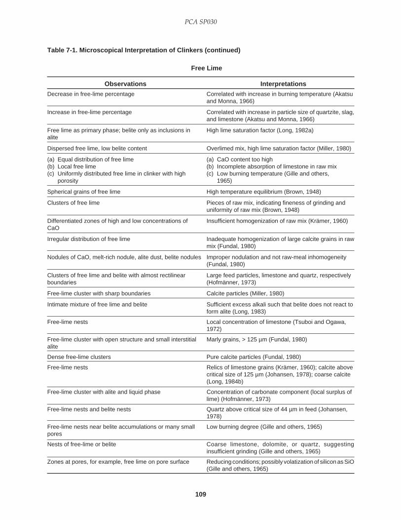
109
PCA SP030
Decrease in free-lime percentage Correlated with increase in burning temperature (Akatsuand Monna, 1966)
Increase in free-lime percentage Correlated with increase in particle size of quartzite, slag,and limestone (Akatsu and Monna, 1966)
Free lime as primary phase; belite only as inclusions in High lime saturation factor (Long, 1982a)alite
Dispersed free lime, low belite content Overlimed mix, high lime saturation factor (Miller, 1980)
(a) Equal distribution of free lime (a) CaO content too high(b) Local free lime (b) Incomplete absorption of limestone in raw mix(c) Uniformly distributed free lime in clinker with high (c) Low burning temperature (Gille and others,
porosity 1965)
Spherical grains of free lime High temperature equilibrium (Brown, 1948)
Clusters of free lime Pieces of raw mix, indicating fineness of grinding anduniformity of raw mix (Brown, 1948)
Differentiated zones of high and low concentrations of Insufficient homogenization of raw mix (Krämer, 1960)CaO
Irregular distribution of free lime Inadequate homogenization of large calcite grains in rawmix (Fundal, 1980)
Nodules of CaO, melt-rich nodule, alite dust, belite nodules Improper nodulation and not raw-meal inhomogeneity(Fundal, 1980)
Clusters of free lime and belite with almost rectilinear Large feed particles, limestone and quartz, respectivelyboundaries (Hofmänner, 1973)
Free-lime cluster with sharp boundaries Calcite particles (Miller, 1980)
Intimate mixture of free lime and belite Sufficient excess alkali such that belite does not react toform alite (Long, 1983)
Free-lime nests Local concentration of limestone (Tsuboi and Ogawa,1972)
Free-lime cluster with open structure and small interstitial Marly grains, > 125 µm (Fundal, 1980)alite
Dense free-lime clusters Pure calcite particles (Fundal, 1980)
Free-lime nests Relics of limestone grains (Krämer, 1960); calcite abovecritical size of 125 µm (Johansen, 1978); coarse calcite(Long, 1984b)
Free-lime cluster with alite and liquid phase Concentration of carbonate component (local surplus oflime) (Hofmänner, 1973)
Free-lime nests and belite nests Quartz above critical size of 44 µm in feed (Johansen,1978)
Free-lime nests near belite accumulations or many small Low burning degree (Gille and others, 1965)pores
Nests of free-lime or belite Coarse limestone, dolomite, or quartz, suggestinginsufficient grinding (Gille and others, 1965)
Zones at pores, for example, free lime on pore surface Reducing conditions; possibly volatization of silicon as SiO(Gille and others, 1965)
Table 7-1. Microscopical Interpretation of Clinkers (continued)
Free Lime
Observations Interpretations
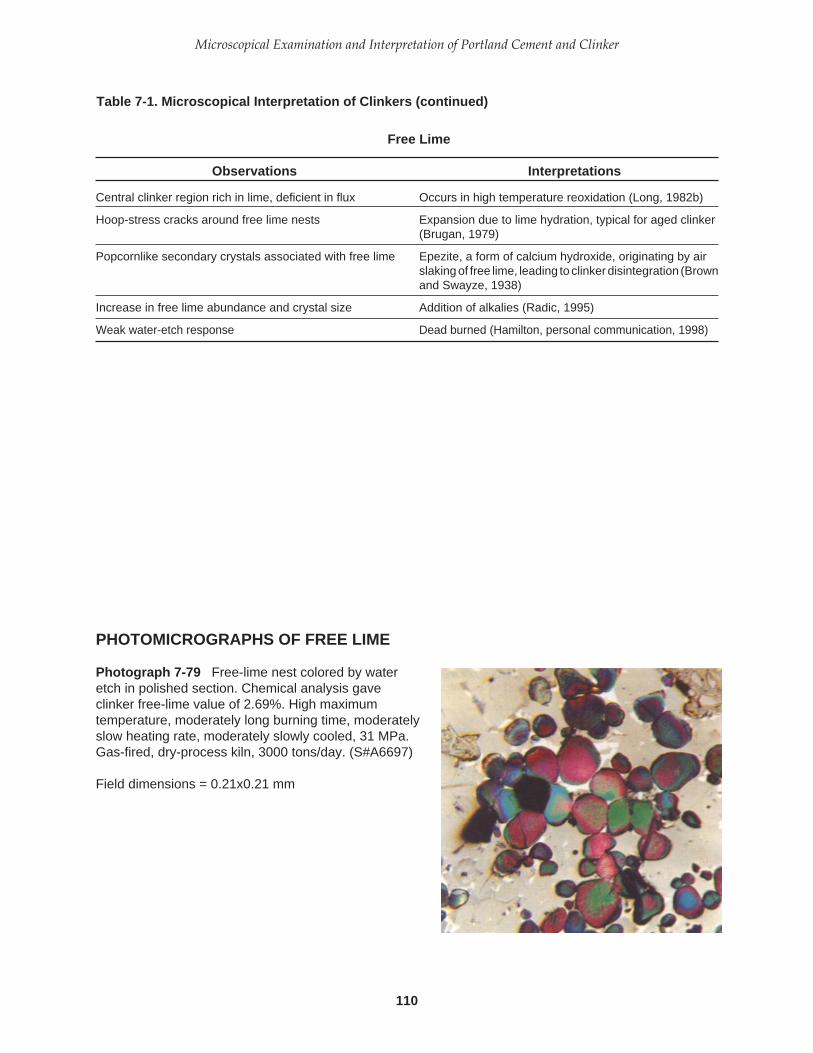
110
Microscopical Examination and Interpretation of Portland Cement and Clinker
Central clinker region rich in lime, deficient in flux Occurs in high temperature reoxidation (Long, 1982b)
Hoop-stress cracks around free lime nests Expansion due to lime hydration, typical for aged clinker(Brugan, 1979)
Popcornlike secondary crystals associated with free lime Epezite, a form of calcium hydroxide, originating by airslaking of free lime, leading to clinker disintegration (Brownand Swayze, 1938)
Increase in free lime abundance and crystal size Addition of alkalies (Radic, 1995)
Weak water-etch response Dead burned (Hamilton, personal communication, 1998)
PHOTOMICROGRAPHS OF FREE LIME
Table 7-1. Microscopical Interpretation of Clinkers (continued)
Photograph 7-79 Free-lime nest colored by wateretch in polished section. Chemical analysis gaveclinker free-lime value of 2.69%. High maximumtemperature, moderately long burning time, moderatelyslow heating rate, moderately slowly cooled, 31 MPa.Gas-fired, dry-process kiln, 3000 tons/day. (S#A6697)
Field dimensions = 0.21x0.21 mm
Free Lime
Observations Interpretations

111
PCA SP030
PHOTOMICROGRAPHS OF FREE LIME (CONTINUED)
Photograph 7-80 Strongly zoned, tan alite with free-lime inclusions and round, coarsely lamellar belite withtan cores, the latter believed to have a relatively lowcalcium-to-silicon ratio. Coarse seashells in feed.Coal- and coke-fired, semiwet-process kiln, 1850 tons/day, 44 MPa. (S#A6698)
Polished sectionNital etchField dimensions = 0.21x0.21 mm
Photograph 7-81 Free-lime nest from coarse calciteparticle in raw feed. Very low liquid phase. Coal- andcoke-fired, dry-process kiln. Moderately high maximumtemperature, long burning time, moderately fastheating rate, quick cooling rate. (S#A6699)
Polished sectionWater etchField dimensions = 0.53x0.53 mm
Photograph 7-82 Free lime in clinker thin section.Crystals exhibit prominent cubic cleavagecharacteristic of free lime. An abundance of free-limenests (some showing original limestone particleoutline), anhedral alite, and extremely nonuniformdistribution of silicates suggests poorly mixed coarsefeed. Dry-process kiln, coal fired. (S#A6700)
Transmitted, plane-polarized lightField dimensions = 0.21x0.21 mm

112
Microscopical Examination and Interpretation of Portland Cement and Clinker
PHOTOMICROGRAPHS OF FREE LIME (CONTINUED)
Photograph 7-84 Cauliflowerlike crystals of epezite,Ca(OH)
2, floating in refractive-index oil. Note green
alite, perhaps related to chromium contamination as aresult of refractory consumption. High maximumtemperature, long burning time, slow heating rate, andquickly cooled. Coal-fired, wet-process kiln. (S#A6702)
Transmitted, plane-polarized lightField dimensions = 0.21x0.21 mm
Photograph 7-83 Clear popcornlike crystals ofepezite, Ca(OH)
2, floating in refractive-index oil. A
product of air slaking of free lime, the 97% change incrystal volume results in clinker disintegration, even insealed containers. Crushed clinker, 45 to 75 µm.(S#A6701)
Transmitted, plane-polarized lightField dimensions = 0.21x0.21 mm
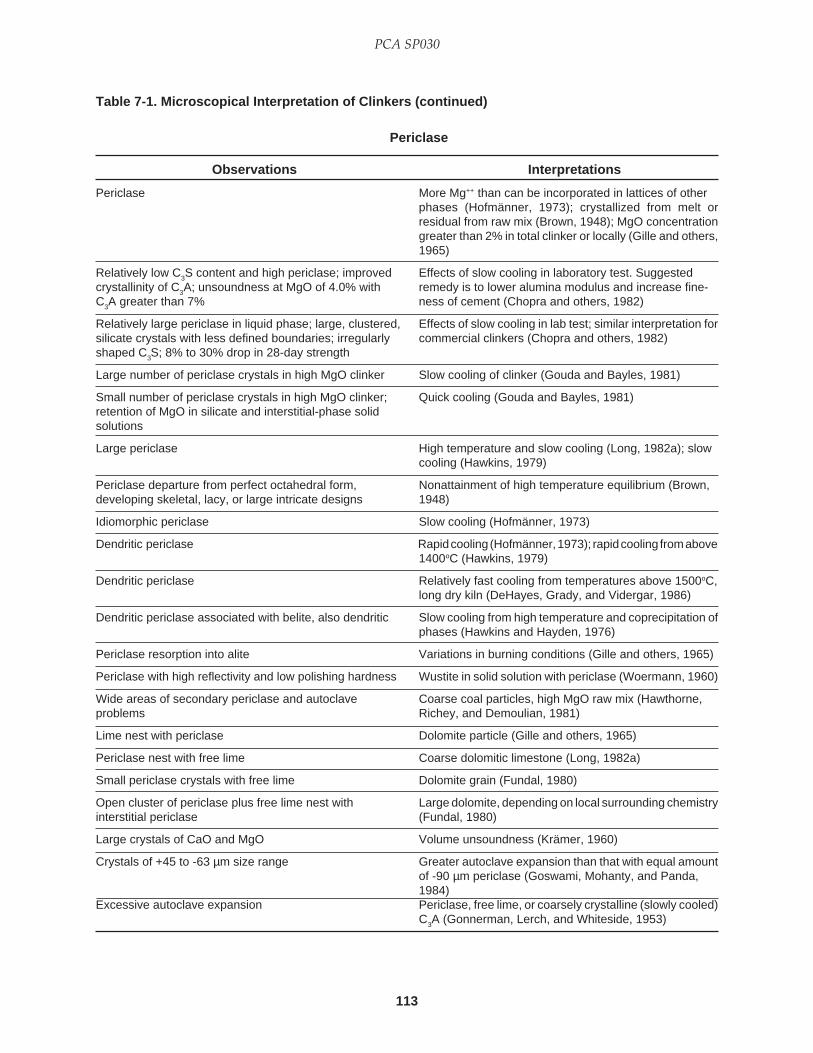
113
PCA SP030
Periclase More Mg++ than can be incorporated in lattices of otherphases (Hofmänner, 1973); crystallized from melt orresidual from raw mix (Brown, 1948); MgO concentrationgreater than 2% in total clinker or locally (Gille and others,1965)
Relatively low C3S content and high periclase; improved Effects of slow cooling in laboratory test. Suggestedcrystallinity of C3A; unsoundness at MgO of 4.0% with remedy is to lower alumina modulus and increase fine-C3A greater than 7% ness of cement (Chopra and others, 1982)
Relatively large periclase in liquid phase; large, clustered, Effects of slow cooling in lab test; similar interpretation forsilicate crystals with less defined boundaries; irregularly commercial clinkers (Chopra and others, 1982)shaped C3S; 8% to 30% drop in 28-day strength
Large number of periclase crystals in high MgO clinker Slow cooling of clinker (Gouda and Bayles, 1981)
Small number of periclase crystals in high MgO clinker; Quick cooling (Gouda and Bayles, 1981)retention of MgO in silicate and interstitial-phase solidsolutions
Large periclase High temperature and slow cooling (Long, 1982a); slowcooling (Hawkins, 1979)
Periclase departure from perfect octahedral form, Nonattainment of high temperature equilibrium (Brown,developing skeletal, lacy, or large intricate designs 1948)
Idiomorphic periclase Slow cooling (Hofmänner, 1973)
Dendritic periclase Rapid cooling (Hofmänner, 1973); rapid cooling from above1400oC (Hawkins, 1979)
Dendritic periclase Relatively fast cooling from temperatures above 1500oC,long dry kiln (DeHayes, Grady, and Vidergar, 1986)
Dendritic periclase associated with belite, also dendritic Slow cooling from high temperature and coprecipitation ofphases (Hawkins and Hayden, 1976)
Periclase resorption into alite Variations in burning conditions (Gille and others, 1965)
Periclase with high reflectivity and low polishing hardness Wustite in solid solution with periclase (Woermann, 1960)
Wide areas of secondary periclase and autoclave Coarse coal particles, high MgO raw mix (Hawthorne,problems Richey, and Demoulian, 1981)
Lime nest with periclase Dolomite particle (Gille and others, 1965)
Periclase nest with free lime Coarse dolomitic limestone (Long, 1982a)
Small periclase crystals with free lime Dolomite grain (Fundal, 1980)
Open cluster of periclase plus free lime nest with Large dolomite, depending on local surrounding chemistryinterstitial periclase (Fundal, 1980)
Large crystals of CaO and MgO Volume unsoundness (Krämer, 1960)
Crystals of +45 to -63 µm size range Greater autoclave expansion than that with equal amountof -90 µm periclase (Goswami, Mohanty, and Panda,1984)
Excessive autoclave expansion Periclase, free lime, or coarsely crystalline (slowly cooled)C3A (Gonnerman, Lerch, and Whiteside, 1953)
Table 7-1. Microscopical Interpretation of Clinkers (continued)
Periclase
Observations Interpretations

114
Microscopical Examination and Interpretation of Portland Cement and Clinker
PHOTOMICROGRAPHS OF PERICLASE
Photograph 7-85 Dendritic periclase formingsubstrate for belite overgrowth (center left). Alitecrystals exhibit facial extensions into matrix of veryfinely microcrystalline aluminate and ferrite. Slowlycooled from high temperature. (S#A6703)
Polished sectionWater etchField dimensions = 0.14x0.14 mm
Photograph 7-86 Marked topographic reliefproduced on polished section by 10-sec nital etchfollowed by 10-sec application on Texmet™ with 0.05-µm alumina. Note dendritic periclase (pinkish gray inmatrix) and silicate zonation. High maximumtemperature, moderately long burning time, slowheating rate, and slow to moderately slow cooling.Coke- and coal-fired, dry-process kiln, 918 tons/day.(S#A6704)
Field dimensions = 0.95x0.95 mm
Photograph 7-87 Ultrathin section showing dendriticpericlase within irregular belite crystals (center andupper left). Section thickness is approximately 10 µm.Coal-fired, wet-process kiln, 444 tons/day. Highmaximum temperature, long burning time, moderatelyslow heating rate, and moderately fast cooling rate.(S#A6705)
Transmitted, plane-polarized lightField dimensions = 0.21x0.21 mm
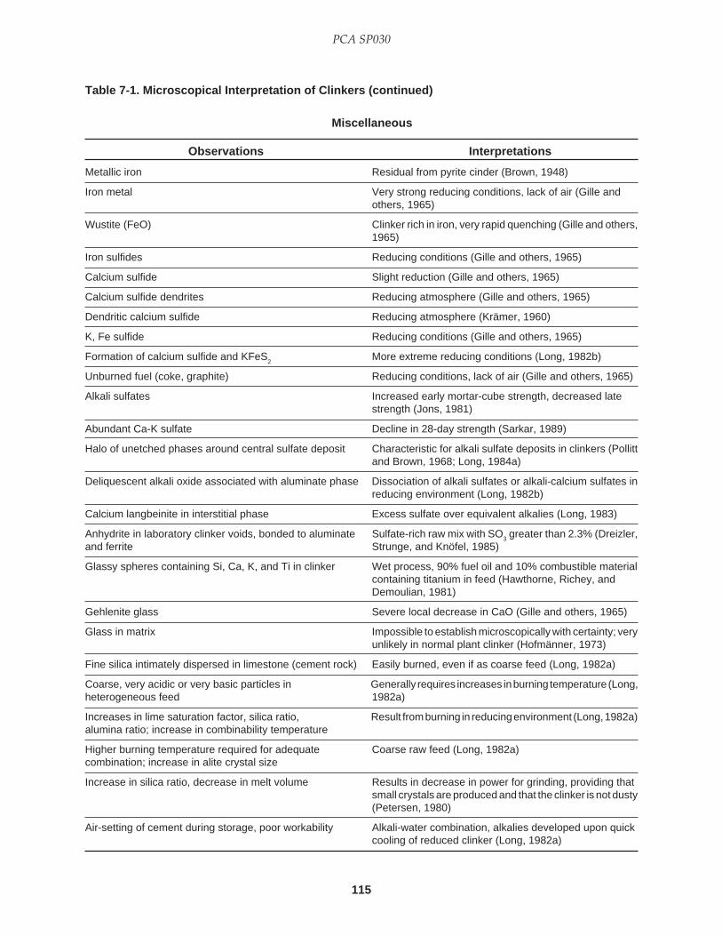
115
PCA SP030
Metallic iron Residual from pyrite cinder (Brown, 1948)
Iron metal Very strong reducing conditions, lack of air (Gille andothers, 1965)
Wustite (FeO) Clinker rich in iron, very rapid quenching (Gille and others,1965)
Iron sulfides Reducing conditions (Gille and others, 1965)
Calcium sulfide Slight reduction (Gille and others, 1965)
Calcium sulfide dendrites Reducing atmosphere (Gille and others, 1965)
Dendritic calcium sulfide Reducing atmosphere (Krämer, 1960)
K, Fe sulfide Reducing conditions (Gille and others, 1965)
Formation of calcium sulfide and KFeS2
More extreme reducing conditions (Long, 1982b)
Unburned fuel (coke, graphite) Reducing conditions, lack of air (Gille and others, 1965)
Alkali sulfates Increased early mortar-cube strength, decreased latestrength (Jons, 1981)
Abundant Ca-K sulfate Decline in 28-day strength (Sarkar, 1989)
Halo of unetched phases around central sulfate deposit Characteristic for alkali sulfate deposits in clinkers (Pollittand Brown, 1968; Long, 1984a)
Deliquescent alkali oxide associated with aluminate phase Dissociation of alkali sulfates or alkali-calcium sulfates inreducing environment (Long, 1982b)
Calcium langbeinite in interstitial phase Excess sulfate over equivalent alkalies (Long, 1983)
Anhydrite in laboratory clinker voids, bonded to aluminate Sulfate-rich raw mix with SO3 greater than 2.3% (Dreizler,and ferrite Strunge, and Knöfel, 1985)
Glassy spheres containing Si, Ca, K, and Ti in clinker Wet process, 90% fuel oil and 10% combustible materialcontaining titanium in feed (Hawthorne, Richey, andDemoulian, 1981)
Gehlenite glass Severe local decrease in CaO (Gille and others, 1965)
Glass in matrix Impossible to establish microscopically with certainty; veryunlikely in normal plant clinker (Hofmänner, 1973)
Fine silica intimately dispersed in limestone (cement rock) Easily burned, even if as coarse feed (Long, 1982a)
Coarse, very acidic or very basic particles in Generally requires increases in burning temperature (Long,heterogeneous feed 1982a)
Increases in lime saturation factor, silica ratio, Result from burning in reducing environment (Long, 1982a)alumina ratio; increase in combinability temperature
Higher burning temperature required for adequate Coarse raw feed (Long, 1982a)combination; increase in alite crystal size
Increase in silica ratio, decrease in melt volume Results in decrease in power for grinding, providing thatsmall crystals are produced and that the clinker is not dusty(Petersen, 1980)
Air-setting of cement during storage, poor workability Alkali-water combination, alkalies developed upon quickcooling of reduced clinker (Long, 1982a)
Table 7-1. Microscopical Interpretation of Clinkers (continued)
Miscellaneous
Observations Interpretations

116
Microscopical Examination and Interpretation of Portland Cement and Clinker
Relatively rapid set of cement Clinker burned and cooled under reducing conditions;highly reactive, well-crystallized, more abundant C3A, slowlycooled (Sylla, 1981)
Relatively high 28-day mortar strength Clinker burned in oxidizing atmosphere (Sylla, 1981)
Decrease in 28-day mortar strength Excess carbon or sulfide in raw feed; clinker burned andslowly cooled in reducing atmosphere (Sylla, 1981)
Depression of 28-day strength; premature stiffening; loss Reducing conditions, slow cooling (Long, 1982b)of workability; cement flowability problems; silo blockages;lighter colored cement
Increase in alite and interstitial percentage; decrease in Correlated with decrease in 28-day mortar strength (Akatsu,belite percentage Monna, and Maeda, 1965)
Increase in free lime and belite percentages; decrease in Correlated with increase in porosity (Akatsu, Monna, andalite and interstitial percentages; decrease in alite size Maeda, 1965)
High proportion of biogenic material, negligible matrix, Ideal limestone raw material for high degree of burningsmall amount of organic substances; compact (Gotthardt and Wilder, 1981)microstructure
Increasing consumption and premature failure of basic Poor raw feed composition and uniformity, resulting inbrick in burning zone, difficulty in forming coating excessive and fluctuating burning temperatures (Chen,
Conjeaud, and Lehoux, 1985)
(a) Fast-setting cement, small C3S crystals, faster cooling (a) Oil-fired cementrate, potassium as K2SO4 (b) Gas-fired cement
(b) Fast-setting cement, higher porosity resulting in (c) Ash-rich coal (Philipp and others, 1981)higher water demand and changing viscosity
(c) Lower initial hydraulic activity and hardness, higherlong-term hardness, higher C2S, and decrease ingrindability
Table 7-1. Microscopical Interpretation of Clinkers (continued)
Miscellaneous
Observations Interpretations

117
PCA SP030
PHOTOMICROGRAPHS OF MISCELLANEOUS PHASES
Photograph 7-90 Dark alkali sulfate in clinker void.Prominently zoned alite. Clearly defined lamellae inrelatively small, round belite. Low maximumtemperature, long burning time, slow heating rate, slowcooling rate, reducing conditions. (S#A6708)
Polished sectionFinal polish with mixture of 0.05 µm alumina, isopropylalcohol, and propylene glycolField dimensions = 0.21x0.21 mm
Photograph 7-88 Dark alkali sulfate deposits on wallof void now filled with epoxy. Coal-fired kiln, wetprocess. High maximum temperature, long burningtime, slow heating rate, quickly cooled, 42 MPa.(S#A6706)
Polished sectionNo etchField dimensions = 0.21x0.21 mm
Photograph 7-89 Dark alkali sulfate as pore andchannel fillings (center and left center). Remainder ofpore is filled with epoxy. XRD analysis indicatesarcanite and aphthitalite. Coal- and coke-fired kiln, wetprocess, 920 tons/day. Moderately high maximumtemperature, moderately long burning time,moderately slow heating rate, quickly cooled.(S#A6707)
Polished sectionNo etchField dimensions = 0.21x0.21 mm

118
Microscopical Examination and Interpretation of Portland Cement and Clinker
PHOTOMICROGRAPHS OF MISCELLANEOUS PHASES (CONTINUED)
Photograph 7-91 Thin section view of alkali sulfate(arrow) as partial filling of void. High maximumtemperature, moderately long burning time, slowheating rate, slow to moderately slow cooling. Four-stage preheater dry-process kiln, coal- and coke-fired,918 tons/day. (S#A6709)
Transmitted, plane-polarized lightField dimensions = 0.14x0.14 mm
Photograph 7-92 Alkali sulfate deposits (arrow) inclinker voids. Clinker SO
3 = 1.12%. Moderately high
maximum temperature, moderately long burning time,slow heating rate, moderately slow cooling rate,33 MPa. Coal- and coke-fired, wet-process kiln, 950tons/day. (S#A6710)
Thin sectionTransmitted, plane-polarized lightField dimensions = 0.21x0.21 mm
Photograph 7-93 Alkali sulfate stained purplish redwith a BaCl
2-KMnO
4 solution. (S#A6711)
Clinker powder, 45- to 75-µm fractionTransmitted, plane-polarized lightField dimensions = 0.21x0.21 mm

119
PCA SP030
PHOTOMICROGRAPHS OF MISCELLANEOUS PHASES (CONTINUED)
Photograph 7-94 Isotropic glass matrix (arrows) inclinker formed at near-melting temperature. Beliteshows prominent lamellar extensions; ferrite is red andstrongly pleochroic. Numerous exsolved dots in belite.(S#A6712)
Thin sectionTransmitted, plane-polarized lightField dimensions = 0.21x0.21 mm
Photograph 7-95 Polished section of clinker particleafter KOH-sugar solution extraction, leaving partlycrystalline material (arrow) and brightly reflectingresidual ferrite (center). (S#A6713)
Nital etchField dimensions = 0.21x0.21 mm
Photograph 7-96 Kiln feed in thin section. Multi-colored particles are grains of polycrystalline limestone(calcite). Gray quartz in center. Brown shale particles(also polycrystalline) indicated with arrows. (S#A6714)
Crossed polarsField dimensions = 1.9x1.9 mm

120
Microscopical Examination and Interpretation of Portland Cement and Clinker
PHOTOMICROGRAPHS OF MISCELLANEOUS PHASES (CONTINUED)
Photograph 7-98 Kiln feed containing coarseparticles of sandstone in which microcline feldspar(showing grid twinning) is common and presumably asource for potassium in the clinker. Fine particles oflimestone comprise most of the feed. (S#A6716)
Thin sectionCrossed polarsField dimensions = 0.53x0.53 mm
Photograph 7-97 Feed particles in thin section. Grayquartz (upper center), microcrystalline limestone (leftcenter and bottom right), and dark shale (center).(S#A6715)
Partially crossed polarsField dimensions = 0.60x0.60 mm

121
PCA SP030
After several years of practice in making and studyingthin sections and polished sections, one gradually de-velops an ability to discern quickly the differencesbetween artifacts of preparation technique and proper-ties of the specimen examined. Unfortunately,misidentifications caused by cracks, scratches, holes,pits, and other surface irregularities (as well as interfer-ence from residual liquids used in the grinding, polish-ing, etching, and cleaning) are common in the pub-lished literature of clinker microscopy. The writer hasfound that only with methodical patience, and with theproper equipment, can a perfect polished section orthin section be produced. If the proper procedure isfollowed the first time, repeated steps in the prepara-tion sequence are rare and, consequently, hours spenttrying to interpret a misidentification are few.
Photomicrographs 8-1 through 8-11 illustrate someof these artifacts and will help the beginning clinkermicroscopist to discriminate actual clinker propertiesfrom the effects of sample preparation. Some problems,however, are not easily solved. For example, interfer-ence of exuding polishing or cleaning liquids withetching media may lead to “halo” patterns of discoloredor unetched crystals around clinker pores and absor-bent phases. Poorly understood chemical reactions maycreate “whiskers” near pores. Polishing vehicles mustbe chemically “pure” or, at least, the impurities mustnot react with any of the clinker phases. Ethanol dena-tured with methanol is not recommended (Prout, letter,1984). Water is a common deleterious contaminant inisopropyl alcohol used for both a polishing vehicle andcleaning solution. Drying with moist air (as from ahouse air line) may lead to a patchy pattern of discolora-tion, some of which could be caused by oil, grease,water, or other impurities. Cracks and gaps betweenphases typically contain polishing powders or pastes.Scratches are particularly troublesome. A few coarse
particles producing scratches during final polishingwill quickly ruin an otherwise perfect section.
One should not, therefore, immediately draw theconclusion that a clinker phase is particularly “reac-tive” if its freshly polished surface exhibits a slight etchor stain due to impure polishing vehicles or cleaningsolutions. Keeping the etchants at constant tempera-ture is recommended to eliminate that persistent ques-tion of temperature effects. Etching and staining shouldbe consistently timed.
Use of the hair dryer to warm the surface of apolished section accelerates etching and staining. There-fore, beware of a premature conclusion of high phasereactivity. Delayed etching may inhibit normal colora-tion and give one a misinterpretation of sluggish phasereactivity.
Microscope light intensity and use of filters shouldalso be employed consistently. Use of a sonic cleaner isalso advisable, but, even so, lint from the polishingcloth or concentrations of dried polishing debris mayremain in clinker pores. Grinding or polishing powderthat dries in clinker pores is almost impossible toremove. Therefore, temporary storage of polished sec-tions in a shallow tray of propylene glycol or other non-reactive liquid between grinding and polishing steps isrecommended to keep the section surface from drying.
Finally, make interpretive generalizations based onthe dominant (most common) clinker characteristics,always attempting to be quantitative and systematic.
CHAPTER 8
Misinterpretations in Clinker Microscopy

122
Microscopical Examination and Interpretation of Portland Cement and Clinker
PHOTOMICROGRAPHS OF ARTIFACTS
Photograph 8-1 Grinding pits remaining on hastilypolished surface of clinker appear somewhat like darkalkali sulfate. (S#A6717)
Polished sectionNo etchField dimensions = 0.21x0.21 mm
Photograph 8-2 Exudation of polishing vehicle(propylene glycol) or cleaning medium (isopropylalcohol) from an alite cleavage on polished sectionsurface. The exudation could be misinterpreted aschemical attack of the alite crystal. (S#A6718)
No etchField dimensions = 0.21x0.21 mm
Photograph 8-3 Etch halo around free lime nestobserved after NH
4Cl etch (“H” in text, Chapter 3). The
halo may be the result of etch interference by liquidexuding from the porous free lime crystals and nearbypores. (S#A6719)
Polished sectionField dimensions = 0.21x0.21 mm
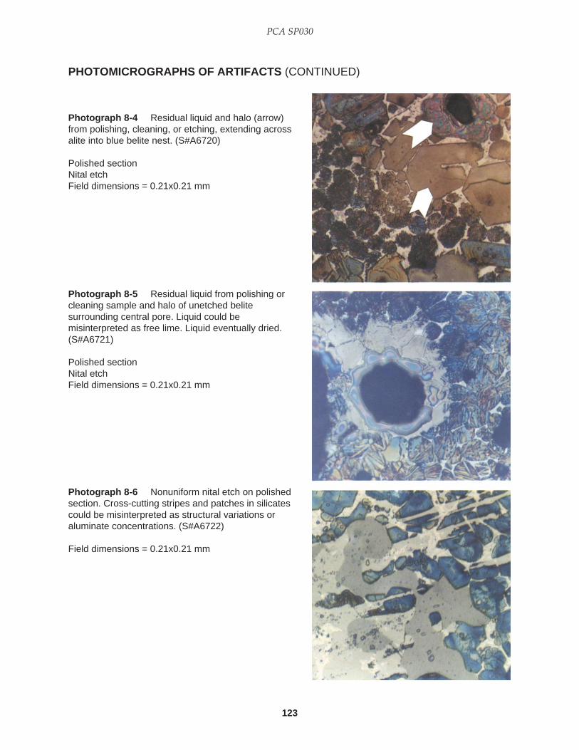
123
PCA SP030
PHOTOMICROGRAPHS OF ARTIFACTS (CONTINUED)
Photograph 8-4 Residual liquid and halo (arrow)from polishing, cleaning, or etching, extending acrossalite into blue belite nest. (S#A6720)
Polished sectionNital etchField dimensions = 0.21x0.21 mm
Photograph 8-5 Residual liquid from polishing orcleaning sample and halo of unetched belitesurrounding central pore. Liquid could bemisinterpreted as free lime. Liquid eventually dried.(S#A6721)
Polished sectionNital etchField dimensions = 0.21x0.21 mm
Photograph 8-6 Nonuniform nital etch on polishedsection. Cross-cutting stripes and patches in silicatescould be misinterpreted as structural variations oraluminate concentrations. (S#A6722)
Field dimensions = 0.21x0.21 mm

124
Microscopical Examination and Interpretation of Portland Cement and Clinker
PHOTOMICROGRAPHS OF ARTIFACTS (CONTINUED)
Photograph 8-7 Polished section showing polishingmarks, probably shallow scratches, extending acrossthree blue alite crystals. (S#A6723)
Nital etchField dimensions = 0.21x0.21 mm
Photograph 8-8 Unidentified, presumably organic,crystals formed on unetched polished-section surface,perhaps as a result of mixing of propylene glycol, usedas a polishing vehicle, and isopropyl alcohol used incleaning. (S#A6724)
Field dimensions = 0.21x0.21 mm
Photograph 8-9 Residual polishing, cleaning, oretching liquids causing blotchy patterns (arrows) onblue alite crystals. Patterns removed after repolishingand drying before etching. Well-differentiated matrix ofaluminate (C
3A) and ferrite is made clearly visible by
application of nital over a previous KOH etch.(S#A6725)
Polished sectionField dimensions = 0.21x0.21 mm

125
PCA SP030
PHOTOMICROGRAPHS OF ARTIFACTS (CONTINUED)
Photograph 8-11 Residual liquid interference withetch, producing dark blobs (arrow) on silicates.(S#A6727)
Polished sectionKOH followed by nital etchField dimensions = 0.21x0.21 mm
Photograph 8-10 Interference by residual liquid orair bubble (arrow) on nital-etched, polished clinkersurface. Note “ghost” boundary (arrow) transectingseveral alite crystals but not visible on the matrix.(S#A6726)
Field dimensions = 0.21x0.21 mm

126
Microscopical Examination and Interpretation of Portland Cement and Clinker

127
PCA SP030
Although this publication is not designed to portraydetails of all the various methods and results of micro-scopical analysis, mention of some of the applicationsand possible pitfalls of the scanning electron micro-scope (SEM) and Electron Dispersive X-ray Analysis(EDXA) is appropriate. Most of the SEM and micro-probe studies to date have dealt with the general char-acterization of clinker phases, including their composi-tional variations. Among the articles describing use ofthe SEM in analysis of clinker microstructure is thework of Gouda (1979a, 1980) in which the variousclinker phases are identified and described in order tointerpret the manufacturing process. Other publica-tions in this field are those of Yamaguchi and Takagi(1968); Regourd and Guinier (1974); Skalny, Mander,and Meyerhoff (1975); and Grattan-Bellew, Quinn, andSereda (1978). The latter publication emphasizes someof the possible problems in SEM analysis, includingpreparation techniques, surface charging, image dis-tortion, phase abundance, and other factors.
Use of the SEM and EDXA in this book has beenprimarily for phase identification, photography, and,in some cases, to gain specific compositional informa-tion. Much of the time spent with the SEM-EDXA hasalso been for the purpose of developing sample polish-ing and etching techniques to facilitate examination. Aword of caution is given to workers who examine onlyfractured clinker surfaces with the SEM: Such surfacesmay not present the observer with a representativecross section of the clinker’s many phases. Moreover,attention is too often directed to well-formed crystalsprojecting into clinker voids, which are ideal places tostudy deposition of alkali sulfates on previously formedcrystal surfaces, but are poor localities for analysis ofmatrix-silicate relationships.
Used properly, the SEM-EDXA allows one to pre-cisely elucidate some of the microstructural and com-positional details unseen with other techniques of mi-
croscopy. Routine application of SEM-EDXA to dailyproduction problems is not common. However, a semi-automatic SEM-EDXA system for routine productionquality control may not be beyond the realm of possibil-ity and practicality. A computer-controlled method ofSEM-EDXA was used by Minnis (1984) to determinethe mineralogy of a sandstone thin section, the dataexpressed in volumetric percentages; the method alsoprovides an approximation of phase grain size and agraphical description of grain locations.
Stutzman (1994) and Stutzman and Odler (1991)illustrated some of the profound implications in appli-cation of electron imaging in clinker and concrete analy-sis, demonstrating the details of microstructures at mag-nifications having resolutions of approximately 0.2 µm.
Bonen and Diamond (1991) with image analysiscomparisons of roller-milled and ball-milled cementsillustrated that two major variants in cement perfor-mance are phase abundance and phase specific surface,particularly in the finer fractions. Roller mill cementsdiffered from ball mill cements in having fewer verysmall particles, lower aspect ratios and shape factors,and differences in the content of particles of specificmineralogies. Alite was relatively enriched in the finestfractions of the ball-milled cement.
In a laboratory study of grinding techniques (ballmill vs. roller mill) Chen and Odler (1992) showed thatroller mill cements exhibit inferior quality because ofhigher water demand, resulting from adverse packingcharacteristics developed during grinding. Microscopi-cally, clear cut differences were observed with regard toparticle size, shape, Blaine, and additionally, dry bulkdensity and flow rates.
Sarkar and Samet (1994), utilizing x-ray diffractionand light and electron microscopy, concluded that anabundance of a potassium-calcium sulfate (from exces-sive insufflation) and unusually large belite crystals(from long residence times) were responsible for low
CHAPTER 9
Scanning Electron Microscopy

128
Microscopical Examination and Interpretation of Portland Cement and Clinker
late-age strength. And, in another plant, finer grind-ing of the raw meal to minimize the occurrence oftightly packed belite nests in clinker resulted in animmediate improvement of strength properties of thecement.
The techniques of sample preparation described inthe following paragraphs are those used by the author.
Clinker powder mounts for SEM-EDXA study aremade by scattering an alcohol-washed, 45- to 75-µmfraction of crushed clinker on a thin film of fresh epoxyresin (plus hardener) on a glass microscope slide. Theparticles stand above the general level of the epoxyfilm, and, after the epoxy hardens, can be subjected torepeated examination with different refractive-indexoils with cover glasses. Using photographs (or mark-ing the area of interest with India ink) and knowingthe orientation of the slide in the SEM-EDXA sampleholder, a specific particle can be found again andanalyzed. Thus the same particle is examined withlight and electron microscopy. Particles are alsomounted directly on the stub for SEM study. Forrelatively precise chemical composition, a suitably
polished section is the preferred surface for EDXA andmicroprobe. Particles mounted with epoxy on a glassor epoxy slide, followed by polishing only the tops ofthe particles (half sections), allow one to gather reli-able chemical data by these electronic methods incombination with observations with transmitted andreflected light.
Polished thin sections are also examined in trans-mitted, polarized light and, after etching for 15 to 30seconds with nital, certain areas are selected and markedwith India ink for SEM-EDXA. The thin section is thenmounted on silver adhesive tape attached to an alumi-num sample holder. Colloidal graphite is painted overthe tape and holder, covering all exposed areas exceptthe sample. After drying, the sample is carbon-coated(approximately 10 nanometers thick) in a vacuumevaporator. Elemental analyses are done with the thinsection or powder mount at -10 to +25 tilt, 15 to 25 keV,timed mode = 100 to 250 seconds. The problem of“smearing” over the polished-section surface is nottotally eliminated but appears to be minor. The prob-lem might be resolved by slight ion-beam etching.

129
PCA SP030
SCANNING ELECTRON MICROSCOPY (SEM)
Photograph 9-1Semiconchoidal fracture surfaceof dense, hard-to-grind clinker.(S#A6728)
SEMField dimensions = 98 µm x 182 µm
Photograph 9-2 Angular aliteand round belite crystals. Boxlikepattern of ferrite crystals in center.Sulfate-resistant cement clinker.(S#A6729)
SEMFractured surfaceField dimensions = 86 µm x 131 µm
Photograph 9-3 Microcracks(from etching?) in alite crystals inferrite matrix. (S#A6730)
SEMNital-etched polished sectionField dimensions = 46 µm x 70 µm
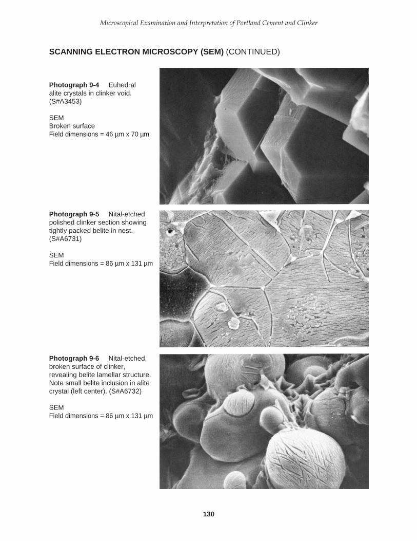
130
Microscopical Examination and Interpretation of Portland Cement and Clinker
SCANNING ELECTRON MICROSCOPY (SEM) (CONTINUED)
Photograph 9-4 Euhedralalite crystals in clinker void.(S#A3453)
SEMBroken surfaceField dimensions = 46 µm x 70 µm
Photograph 9-5 Nital-etchedpolished clinker section showingtightly packed belite in nest.(S#A6731)
SEMField dimensions = 86 µm x 131 µm
Photograph 9-6 Nital-etched,broken surface of clinker,revealing belite lamellar structure.Note small belite inclusion in alitecrystal (left center). (S#A6732)
SEMField dimensions = 86 µm x 131 µm

131
PCA SP030
SCANNING ELECTRON MICROSCOPY (SEM) (CONTINUED)
Photograph 9-7 Apparentlyfeatureless surfaces of roundbelite crystals on broken clinker.Light-colored ferrite. (S#A3454)
SEMField dimensions = 18 µm x 28 µm
Photograph 9-8 Belite crystalshowing lamellae on outersurface and ferrite deposit (whitematerial). (S#A6733)
SEMField dimensions = 18 µm x 28 µm
Photograph 9-9 Nital-etchedpolished clinker section showingbelite fringe on alite (upper half)and lamellar extensions of belite(lower border). (S#A6734)
SEMField dimensions = 30 µm x 46 µm

132
Microscopical Examination and Interpretation of Portland Cement and Clinker
SCANNING ELECTRON MICROSCOPY (SEM) (CONTINUED)
Photograph 9-10 Sulfate-resistant clinker, slowly cooledand ferrite-rich, showing belitelamellae extending into matrix.Gas-fired, wet-process kiln, 830tons/day. (S#A6735)
SEMNital-etched polished sectionField dimensions = 46 µm x 70 µm
Photograph 9-11 Nital-etchedpolished section showing well-developed lamellae in belitecrystals. (S#A6736)
SEMField dimensions = 46 µm x 70 µm
Photograph 9-12 Lamellarstructure of belite revealed afternital etch on polished section.(S#A3456)
SEMField dimensions = 46 µm x 70 µm
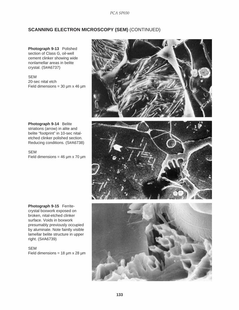
133
PCA SP030
SCANNING ELECTRON MICROSCOPY (SEM) (CONTINUED)
Photograph 9-13 Polishedsection of Class G, oil-wellcement clinker showing widenonlamellar areas in belitecrystal. (S#A6737)
SEM20-sec nital etchField dimensions = 30 µm x 46 µm
Photograph 9-14 Belitestriations (arrow) in alite andbelite “footprint” in 10-sec nital-etched clinker polished section.Reducing conditions. (S#A6738)
SEMField dimensions = 46 µm x 70 µm
Photograph 9-15 Ferrite-crystal boxwork exposed onbroken, nital-etched clinkersurface. Voids in boxworkpresumably previously occupiedby aluminate. Note faintly visiblelamellar belite structure in upperright. (S#A6739)
SEMField dimensions = 18 µm x 28 µm
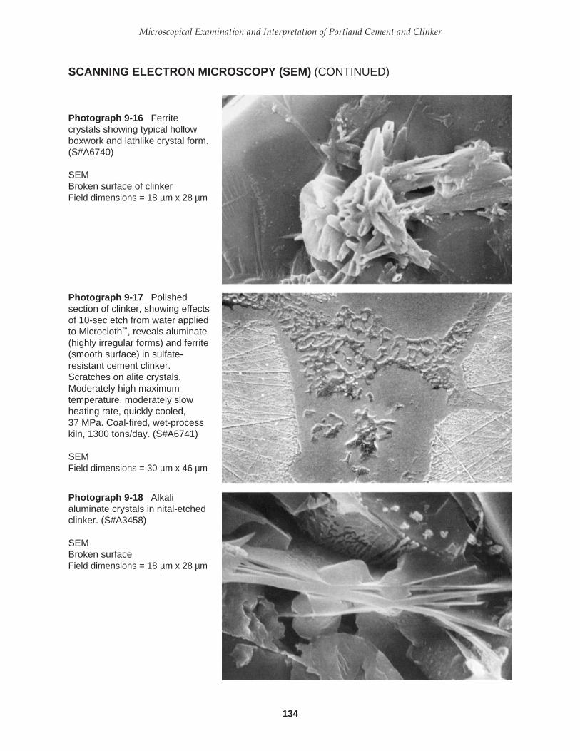
134
Microscopical Examination and Interpretation of Portland Cement and Clinker
SCANNING ELECTRON MICROSCOPY (SEM) (CONTINUED)
Photograph 9-16 Ferritecrystals showing typical hollowboxwork and lathlike crystal form.(S#A6740)
SEMBroken surface of clinkerField dimensions = 18 µm x 28 µm
Photograph 9-17 Polishedsection of clinker, showing effectsof 10-sec etch from water appliedto Microcloth™, reveals aluminate(highly irregular forms) and ferrite(smooth surface) in sulfate-resistant cement clinker.Scratches on alite crystals.Moderately high maximumtemperature, moderately slowheating rate, quickly cooled,37 MPa. Coal-fired, wet-processkiln, 1300 tons/day. (S#A6741)
SEMField dimensions = 30 µm x 46 µm
Photograph 9-18 Alkalialuminate crystals in nital-etchedclinker. (S#A3458)
SEMBroken surfaceField dimensions = 18 µm x 28 µm

135
PCA SP030
SCANNING ELECTRON MICROSCOPY (SEM) (CONTINUED)
Photograph 9-19 Polishedsection of clinker with a nital etch(20 seconds) showing a periclaseskeleton (arrow) within belite.(S#A6742)
SEMField dimensions = 46 µm x 70 µm
Photograph 9-20 Periclasecrystal amidst calciumhydroxide, left and right, thelatter resulting from free-limehydration (air-slaking).(S#A6743)
SEMBroken clinker surfaceField dimensions = 9 µm x 14 µm
Photograph 9-21Cauliflowerlike calcium hydroxidecrystals (presumably epezite),from hydration of free lime (airslaking), and round, graypericlase crystals in a nest,suggesting coarse dolomite in thefeed. (S#A6744)
SEMBroken clinker surfaceField dimensions = 46 µm x 70 µm
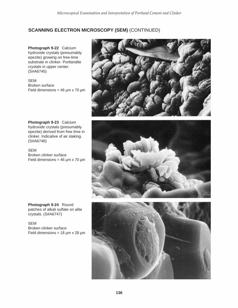
136
Microscopical Examination and Interpretation of Portland Cement and Clinker
SCANNING ELECTRON MICROSCOPY (SEM) (CONTINUED)
Photograph 9-22 Calciumhydroxide crystals (presumablyepezite) growing on free-limesubstrate in clinker. Portlanditecrystals in upper center.(S#A6745)
SEMBroken surfaceField dimensions = 46 µm x 70 µm
Photograph 9-23 Calciumhydroxide crystals (presumablyepezite) derived from free lime inclinker. Indicative of air slaking.(S#A6746)
SEMBroken clinker surfaceField dimensions = 46 µm x 70 µm
Photograph 9-24 Roundpatches of alkali sulfate on alitecrystals. (S#A6747)
SEMBroken clinker surfaceField dimensions = 18 µm x 28 µm

137
PCA SP030
SCANNING ELECTRON MICROSCOPY (SEM) (CONTINUED)
Photograph 9-26 Alkali-sulfatedeposit on void wall in nital-etched clinker polished section.EDXA data (expressed inapproximate percentages) onbright ridges: S = 36.0%, K =38.5, Ca = 25.4, Fe = 0.1; darkpits between ridges: S = 37.8,K = 46.1, Ca = 14.9, Fe = 0.4.(S#A6749)
SEMField dimensions = 18 µm x 28 µm
Photograph 9-25 Alite crystalwith attached alkali sulfates.Lamellar structure in beliterevealed in upper right corner.30-min maleic acid etch oncrushed, sieved clinker.(S#A6748)
SEMField dimensions = 30 µm x 46 µm

138
Microscopical Examination and Interpretation of Portland Cement and Clinker

139
PCA SP030
This chapter is about petrography and petrographicmethods as applied to an elementary examination ofraw materials, and its purpose is to describe how oneperforms the examination. A brief review of recentliterature given below clearly illustrates the value ofpetrography to cement raw material investigations, muchlike it is in ceramic science. The writer strongly believesthat routine proficiency in cement quality control withmicroscopy begins in the quarry and continues throughthe final product, the cement, and even the concrete.
The intricate chemical and physical processesthat take place in the burning of portland cement rawfeed are much too complicated to be dealt with here.But, as an introduction to these subjects, a brief surveyof selected recent literature and a presentation of el-ementary steps in raw feed examination are offered.This is not to imply that all needed information hasbeen published, for much systematic research remainsto be done. Our understanding of clinkering, however,demands an appreciation of exactly what it is that weare burning.
SELECTED LITERATURE REVIEW
The following summary of selected papers representsmaterial published, for the most part, in the last 10 to 20years. Emphasis is given to studies that suggest corre-lations of feed and clinker characteristics with kilnconditions, such as rate of heating, time at maximumtemperature, maximum temperature, rate of cooling,and burnability. It is virtually impossible to present aclear-cut separation of these subjects in this book, thusone might find discussions of similar topics in severalprevious chapters. In other words, not all of the infor-mation on quartz in relation to belite nests and feedfineness, for example, is gathered in this chapter, andso on. Some of the salient observations and interpreta-tions recorded in the recent literature, relating the
mineralogy and texture of feed and clinker, are listedin the lengthy table making up most of Chapter 7,Microscopical Interpretation of Clinkers.
Akatsu and Hanada (1963) investigated theburnability of “clays” containing various measuredpercentages of silt- and sand-sized metamorphic andsedimentary rock fragments, feldspar, volcanic rockfragments, ordinary quartz, and chert in 66 samples.Burnability was shown to increase with increasingpercentages of metamorphic and sedimentary rockfragments, all polycrystalline rock types.
Miller (1976), building on the work of Akatsu andIkeda (1971) and those mentioned above, emphasizedraw feed homogeneity and uniformity, and listedsilica particles in order of decreasing burnability: finequartz (<44 µm), chert (most burnable), silica gel, veinquartz, and quartzite. Coarse quartz (88 to 149 µm)was said to be less burnable than quartzite. The impor-tance of keeping the siliceous raw feed, particularlythe quartz, particle size below approximately 45 µmwas shown, decreasing the energy requirement toreduce the level of free lime in clinker. Free limedecreased rapidly as the temperature increased, espe-cially with fine-grained feed.
With the use of Ono’s Method and microscopy ofraw feed, clinker, cement, gypsum, and kiln dust,coupled with laboratory burns and sieve analysis ofthe raw feed, Vanisko (1978) demonstrated the delete-rious effect of belite nests in development of mortarstrength. He showed that coarse quartz was corre-lated with numerous large belite nests and, when theraw sand was separately and more finely ground,mortar strengths jumped to 41 MPa.
By reducing the coarse fractions of the feed, therebydecreasing the coarse siliceous particle percentages,and adjusting the raw mix chemistry (addition of slag,among other changes) so as to lower the silica modu-lus, Legate (1987) demonstrated a major improvement
CHAPTER 10
Microscopical Examination ofPortland Cement Raw Materials
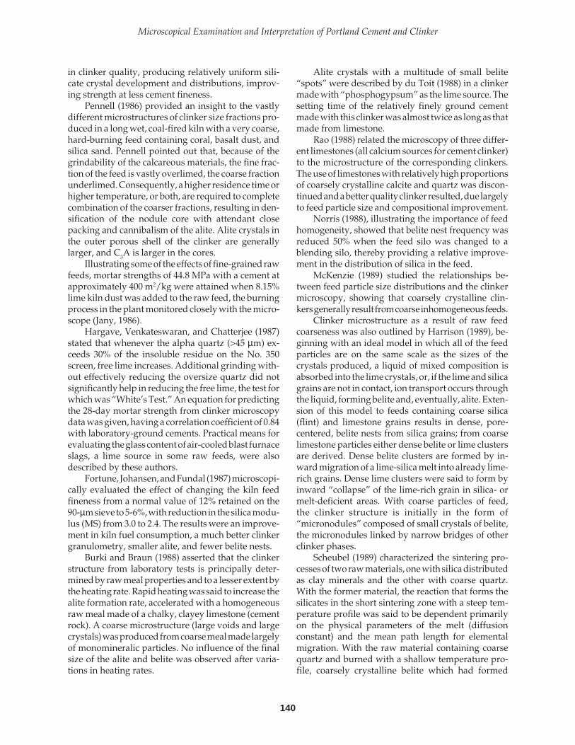
140
Microscopical Examination and Interpretation of Portland Cement and Clinker
in clinker quality, producing relatively uniform sili-cate crystal development and distributions, improv-ing strength at less cement fineness.
Pennell (1986) provided an insight to the vastlydifferent microstructures of clinker size fractions pro-duced in a long wet, coal-fired kiln with a very coarse,hard-burning feed containing coral, basalt dust, andsilica sand. Pennell pointed out that, because of thegrindability of the calcareous materials, the fine frac-tion of the feed is vastly overlimed, the coarse fractionunderlimed. Consequently, a higher residence time orhigher temperature, or both, are required to completecombination of the coarser fractions, resulting in den-sification of the nodule core with attendant closepacking and cannibalism of the alite. Alite crystals inthe outer porous shell of the clinker are generallylarger, and C3A is larger in the cores.
Illustrating some of the effects of fine-grained rawfeeds, mortar strengths of 44.8 MPa with a cement atapproximately 400 m2/kg were attained when 8.15%lime kiln dust was added to the raw feed, the burningprocess in the plant monitored closely with the micro-scope (Jany, 1986).
Hargave, Venkateswaran, and Chatterjee (1987)stated that whenever the alpha quartz (>45 µm) ex-ceeds 30% of the insoluble residue on the No. 350screen, free lime increases. Additional grinding with-out effectively reducing the oversize quartz did notsignificantly help in reducing the free lime, the test forwhich was “White’s Test.” An equation for predictingthe 28-day mortar strength from clinker microscopydata was given, having a correlation coefficient of 0.84with laboratory-ground cements. Practical means forevaluating the glass content of air-cooled blast furnaceslags, a lime source in some raw feeds, were alsodescribed by these authors.
Fortune, Johansen, and Fundal (1987) microscopi-cally evaluated the effect of changing the kiln feedfineness from a normal value of 12% retained on the90-µm sieve to 5-6%, with reduction in the silica modu-lus (MS) from 3.0 to 2.4. The results were an improve-ment in kiln fuel consumption, a much better clinkergranulometry, smaller alite, and fewer belite nests.
Burki and Braun (1988) asserted that the clinkerstructure from laboratory tests is principally deter-mined by raw meal properties and to a lesser extent bythe heating rate. Rapid heating was said to increase thealite formation rate, accelerated with a homogeneousraw meal made of a chalky, clayey limestone (cementrock). A coarse microstructure (large voids and largecrystals) was produced from coarse meal made largelyof monomineralic particles. No influence of the finalsize of the alite and belite was observed after varia-tions in heating rates.
Alite crystals with a multitude of small belite“spots” were described by du Toit (1988) in a clinkermade with “phosphogypsum” as the lime source. Thesetting time of the relatively finely ground cementmade with this clinker was almost twice as long as thatmade from limestone.
Rao (1988) related the microscopy of three differ-ent limestones (all calcium sources for cement clinker)to the microstructure of the corresponding clinkers.The use of limestones with relatively high proportionsof coarsely crystalline calcite and quartz was discon-tinued and a better quality clinker resulted, due largelyto feed particle size and compositional improvement.
Norris (1988), illustrating the importance of feedhomogeneity, showed that belite nest frequency wasreduced 50% when the feed silo was changed to ablending silo, thereby providing a relative improve-ment in the distribution of silica in the feed.
McKenzie (1989) studied the relationships be-tween feed particle size distributions and the clinkermicroscopy, showing that coarsely crystalline clin-kers generally result from coarse inhomogeneous feeds.
Clinker microstructure as a result of raw feedcoarseness was also outlined by Harrison (1989), be-ginning with an ideal model in which all of the feedparticles are on the same scale as the sizes of thecrystals produced, a liquid of mixed composition isabsorbed into the lime crystals, or, if the lime and silicagrains are not in contact, ion transport occurs throughthe liquid, forming belite and, eventually, alite. Exten-sion of this model to feeds containing coarse silica(flint) and limestone grains results in dense, pore-centered, belite nests from silica grains; from coarselimestone particles either dense belite or lime clustersare derived. Dense belite clusters are formed by in-ward migration of a lime-silica melt into already lime-rich grains. Dense lime clusters were said to form byinward “collapse” of the lime-rich grain in silica- ormelt-deficient areas. With coarse particles of feed,the clinker structure is initially in the form of“micronodules” composed of small crystals of belite,the micronodules linked by narrow bridges of otherclinker phases.
Scheubel (1989) characterized the sintering pro-cesses of two raw materials, one with silica distributedas clay minerals and the other with coarse quartz.With the former material, the reaction that forms thesilicates in the short sintering zone with a steep tem-perature profile was said to be dependent primarilyon the physical parameters of the melt (diffusionconstant) and the mean path length for elementalmigration. With the raw material containing coarsequartz and burned with a shallow temperature pro-file, coarsely crystalline belite which had formed
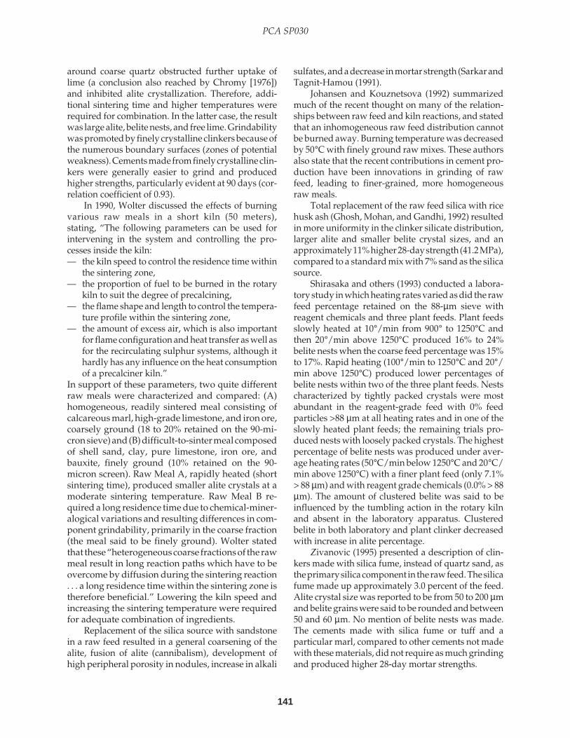
141
PCA SP030
around coarse quartz obstructed further uptake oflime (a conclusion also reached by Chromy [1976])and inhibited alite crystallization. Therefore, addi-tional sintering time and higher temperatures wererequired for combination. In the latter case, the resultwas large alite, belite nests, and free lime. Grindabilitywas promoted by finely crystalline clinkers because ofthe numerous boundary surfaces (zones of potentialweakness). Cements made from finely crystalline clin-kers were generally easier to grind and producedhigher strengths, particularly evident at 90 days (cor-relation coefficient of 0.93).
In 1990, Wolter discussed the effects of burningvarious raw meals in a short kiln (50 meters),stating, “The following parameters can be used forintervening in the system and controlling the pro-cesses inside the kiln:— the kiln speed to control the residence time within
the sintering zone,— the proportion of fuel to be burned in the rotary
kiln to suit the degree of precalcining,— the flame shape and length to control the tempera-
ture profile within the sintering zone,— the amount of excess air, which is also important
for flame configuration and heat transfer as well asfor the recirculating sulphur systems, although ithardly has any influence on the heat consumptionof a precalciner kiln.”
In support of these parameters, two quite differentraw meals were characterized and compared: (A)homogeneous, readily sintered meal consisting ofcalcareous marl, high-grade limestone, and iron ore,coarsely ground (18 to 20% retained on the 90-mi-cron sieve) and (B) difficult-to-sinter meal composedof shell sand, clay, pure limestone, iron ore, andbauxite, finely ground (10% retained on the 90-micron screen). Raw Meal A, rapidly heated (shortsintering time), produced smaller alite crystals at amoderate sintering temperature. Raw Meal B re-quired a long residence time due to chemical-miner-alogical variations and resulting differences in com-ponent grindability, primarily in the coarse fraction(the meal said to be finely ground). Wolter statedthat these “heterogeneous coarse fractions of the rawmeal result in long reaction paths which have to beovercome by diffusion during the sintering reaction. . . a long residence time within the sintering zone istherefore beneficial.” Lowering the kiln speed andincreasing the sintering temperature were requiredfor adequate combination of ingredients.
Replacement of the silica source with sandstonein a raw feed resulted in a general coarsening of thealite, fusion of alite (cannibalism), development ofhigh peripheral porosity in nodules, increase in alkali
sulfates, and a decrease in mortar strength (Sarkar andTagnit-Hamou (1991).
Johansen and Kouznetsova (1992) summarizedmuch of the recent thought on many of the relation-ships between raw feed and kiln reactions, and statedthat an inhomogeneous raw feed distribution cannotbe burned away. Burning temperature was decreasedby 50°C with finely ground raw mixes. These authorsalso state that the recent contributions in cement pro-duction have been innovations in grinding of rawfeed, leading to finer-grained, more homogeneousraw meals.
Total replacement of the raw feed silica with ricehusk ash (Ghosh, Mohan, and Gandhi, 1992) resultedin more uniformity in the clinker silicate distribution,larger alite and smaller belite crystal sizes, and anapproximately 11% higher 28-day strength (41.2 MPa),compared to a standard mix with 7% sand as the silicasource.
Shirasaka and others (1993) conducted a labora-tory study in which heating rates varied as did the rawfeed percentage retained on the 88-µm sieve withreagent chemicals and three plant feeds. Plant feedsslowly heated at 10°/min from 900° to 1250°C andthen 20°/min above 1250°C produced 16% to 24%belite nests when the coarse feed percentage was 15%to 17%. Rapid heating (100°/min to 1250°C and 20°/min above 1250°C) produced lower percentages ofbelite nests within two of the three plant feeds. Nestscharacterized by tightly packed crystals were mostabundant in the reagent-grade feed with 0% feedparticles >88 µm at all heating rates and in one of theslowly heated plant feeds; the remaining trials pro-duced nests with loosely packed crystals. The highestpercentage of belite nests was produced under aver-age heating rates (50°C/min below 1250°C and 20°C/min above 1250°C) with a finer plant feed (only 7.1%> 88 µm) and with reagent grade chemicals (0.0% > 88µm). The amount of clustered belite was said to beinfluenced by the tumbling action in the rotary kilnand absent in the laboratory apparatus. Clusteredbelite in both laboratory and plant clinker decreasedwith increase in alite percentage.
Zivanovic (1995) presented a description of clin-kers made with silica fume, instead of quartz sand, asthe primary silica component in the raw feed. The silicafume made up approximately 3.0 percent of the feed.Alite crystal size was reported to be from 50 to 200 µmand belite grains were said to be rounded and between50 and 60 µm. No mention of belite nests was made.The cements made with silica fume or tuff and aparticular marl, compared to other cements not madewith these materials, did not require as much grindingand produced higher 28-day mortar strengths.

142
Microscopical Examination and Interpretation of Portland Cement and Clinker
A microcrystalline limestone, as opposed to alimestone made of coarse fossil shells and other calciteparticles, was shown to grind differently, producing araw meal with a relatively uniform and finer particlesize distribution, leading to an improved burnability(Sas, 1997).
Dreizler and Schafer (1990) also stated that theconcentration of less active quartz in the coarse frac-tion of the raw material decreases sinterability, in-creases energy requirements or free lime, and increasesdevelopment of belite nests. A chemical method ofevaluating the burnability of various particle-size frac-tions of the feed, involving the calculation of the“weighted mean of the lime saturation standard,”along with microscopy of the feeds, was said to be avery cost-effective tool in control of energy consump-tion and cement quality. For this study, six raw feedsize fractions, from <32 to >200 µm, were investigated.
In the present writer’s opinion, this summary ofselected papers indicates that a detailed understand-ing of the raw feed mineralogy-particle size relation-ship and the effects of the temperature profile in a kilnis absolutely mandatory for continued quality control.These papers, and many others of similar subjectmatter, demonstrate the practicality of cement plantmicroscopy. The microscope, perhaps better than anyother instrument of analysis, and certainly as a cor-roborative tool, provides the means for visual appre-ciation of the cement-making process. But what kindof training is necessary? What are the essential micro-scopical observations and the “standard” microscopi-cal procedures that one can use to help ensure aquality product? Knowing the microscopical natureof the raw materials is the first step.
RAW MATERIAL EXAMINATION
A chemical analysis alone cannot describe the form,particle size, or mineralogy of the feed. SiO2 from achemical analysis does not necessarily mean quartz,nor does Fe2O3 necessarily imply hematite. Analysis byX-ray diffraction (XRD) quite accurately records mostof the detectable mineralogical varieties and with cali-brated standards allows an estimation of abundance.But XRD cannot elucidate the particle form or size, andvirtually misses the occurrence of amorphous materi-als such as glass or poorly crystalline materials such aslimonite, FeO(OH), a major constituent in many ironsources for portland cement. Phases below the detec-tion limit by XRD can easily be seen in the microscope.However, chemical and XRD analyses of each of theraw materials individually, in sieved fractions, and intheir blended combination in the feed, are immenselyhelpful, indeed strongly recommended, for routine
quality control, but are far less applicable to clinkerproduction without microscopy. Microscopy givesvisual form to the data from other methods of analysis.
A working knowledge of some of the principles ofelementary optical mineralogy is obviously neces-sary. One should be conversant with the concepts ofpolarized light transmission through isotropic andanisotropic crystalline solids, birefringence, interfer-ence colors, index of refraction, cleavage, fracture, andso on—in short, the appearance of rocks and mineralsunder the stereomicroscope and the polarized-lightmicroscope. The use of reflected light, as in metallog-raphy, is also necessary for the opaque materials.Those trained in geology, ceramics, and material sci-ence are normally familiar with these subjects.
Consequently, the purposes of microscopical ex-amination of raw materials are to describe the mineral-ogy, and to estimate the mineral abundances and par-ticle size variations, all of which bears directly on theease with which the material combines in the kiln. Theimportance of microscopy can hardly be overstated.
Petrographic Identification of RawFeed Constituents
Microscopical examination should start in the quarrywhere samples of each of the varieties of limestone,sandstone, shale, etc., are collected, layer by layer, bya geologist or someone with an adequate knowledgeof the quarry. An assumption of the mineralogy ofmost quarried materials, as well as many of the indus-trial byproducts, is commonly questionable. Repre-sentative portions of each rock variety are sent off, ifnecessary, for thin sectioning (see partial list of profes-sional companies in Table 11-3). Some of these compa-nies will also stain the thin sections as directed. An-other portion of the rock is crushed in the plant labo-ratory with a mortar and pestle or other suitablecrushing device, and sieved to produce a 45- to 75-µmfraction for examination in a powder mount, using, atfirst, a liquid with a refractive index of approximately1.542. Samples of nondeposit materials, such as slag,fly ash, bottom ash, rice husk ash, clay catalyst, etc., areexamined similarly. Insoluble residues from a portion of this sievefraction can be prepared with 20% acetic acid and 20%HCl; the residue is then sieved to retain the >45-µmmaterial which can then be studied in powder mount,thin section, or both. The difference in the two resi-dues is related to dolomite percentage.
Commercially prepared thin sections (Table 11-3)are studied along with the powder mounts in order tosee which features of the “whole rock” can be ob-served in the powder particles, thus facilitating their
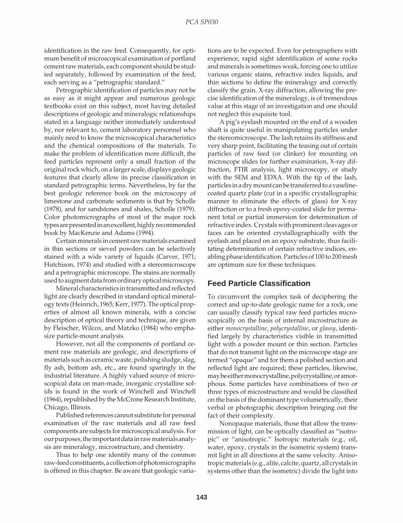
143
PCA SP030
identification in the raw feed. Consequently, for opti-mum benefit of microscopical examination of portlandcement raw materials, each component should be stud-ied separately, followed by examination of the feed,each serving as a “petrographic standard.”
Petrographic identification of particles may not beas easy as it might appear and numerous geologictextbooks exist on this subject, most having detaileddescriptions of geologic and mineralogic relationshipsstated in a language neither immediately understoodby, nor relevant to, cement laboratory personnel whomainly need to know the microscopical characteristicsand the chemical compositions of the materials. Tomake the problem of identification more difficult, thefeed particles represent only a small fraction of theoriginal rock which, on a larger scale, displays geologicfeatures that clearly allow its precise classification instandard petrographic terms. Nevertheless, by far thebest geologic reference book on the microscopy oflimestone and carbonate sediments is that by Scholle(1978), and for sandstones and shales, Scholle (1979).Color photomicrographs of most of the major rocktypes are presented in an excellent, highly recommendedbook by MacKenzie and Adams (1994).
Certain minerals in cement raw materials examinedin thin sections or sieved powders can be selectivelystained with a wide variety of liquids (Carver, 1971;Hutchison, 1974) and studied with a stereomicroscopeand a petrographic microscope. The stains are normallyused to augment data from ordinary optical microscopy.
Mineral characteristics in transmitted and reflectedlight are clearly described in standard optical mineral-ogy texts (Heinrich, 1965; Kerr, 1977). The optical prop-erties of almost all known minerals, with a concisedescription of optical theory and technique, are givenby Fleischer, Wilcox, and Matzko (1984) who empha-size particle-mount analysis.
However, not all the components of portland ce-ment raw materials are geologic, and descriptions ofmaterials such as ceramic waste, polishing sludge, slag,fly ash, bottom ash, etc., are found sparingly in theindustrial literature. A highly valued source of micro-scopical data on man-made, inorganic crystalline sol-ids is found in the work of Winchell and Winchell(1964), republished by the McCrone Research Institute,Chicago, Illinois.
Published references cannot substitute for personalexamination of the raw materials and all raw feedcomponents are subjects for microscopical analysis. Forour purposes, the important data in raw materials analy-sis are mineralogy, microstructure, and chemistry.
Thus to help one identify many of the commonraw-feed constituents, a collection of photomicrographsis offered in this chapter. Be aware that geologic varia-
tions are to be expected. Even for petrographers withexperience, rapid sight identification of some rocksand minerals is sometimes weak, forcing one to utilizevarious organic stains, refractive index liquids, andthin sections to define the mineralogy and correctlyclassify the grain. X-ray diffraction, allowing the pre-cise identification of the mineralogy, is of tremendousvalue at this stage of an investigation and one shouldnot neglect this exquisite tool.
A pig’s eyelash mounted on the end of a woodenshaft is quite useful in manipulating particles underthe stereomicroscope. The lash retains its stiffness andvery sharp point, facilitating the teasing out of certainparticles of raw feed (or clinker) for mounting onmicroscope slides for further examination, X-ray dif-fraction, FTIR analysis, light microscopy, or studywith the SEM and EDXA. With the tip of the lash,particles in a dry mount can be transferred to a vaseline-coated quartz plate (cut in a specific crystallographicmanner to eliminate the effects of glass) for X-raydiffraction or to a fresh epoxy-coated slide for perma-nent total or partial immersion for determination ofrefractive index. Crystals with prominent cleavages orfaces can be oriented crystallographically with theeyelash and placed on an epoxy substrate, thus facili-tating determination of certain refractive indices, en-abling phase identification. Particles of 100 to 200 meshare optimum size for these techniques.
Feed Particle Classification
To circumvent the complex task of deciphering thecorrect and up-to-date geologic name for a rock, onecan usually classify typical raw feed particles micro-scopically on the basis of internal microstructure aseither monocrystalline, polycrystalline, or glassy, identi-fied largely by characteristics visible in transmittedlight with a powder mount or thin section. Particlesthat do not transmit light on the microscope stage aretermed “opaque” and for them a polished section andreflected light are required; these particles, likewise,may be either monocrystalline, polycrystalline, or amor-phous. Some particles have combinations of two orthree types of microstructure and would be classifiedon the basis of the dominant type volumetrically, theirverbal or photographic description bringing out thefact of their complexity.
Nonopaque materials, those that allow the trans-mission of light, can be optically classified as “isotro-pic” or “anisotropic.” Isotropic materials (e.g., oil,water, epoxy, crystals in the isometric system) trans-mit light in all directions at the same velocity. Aniso-tropic materials (e.g., alite, calcite, quartz, all crystals insystems other than the isometric) divide the light into

144
Microscopical Examination and Interpretation of Portland Cement and Clinker
two waves vibrating in mutually perpendicular planesat different velocities and directions.
Limestone, like sandstone, is a polycrystalline rockcomprised of various crystalline phases (mostly cal-cite). Microcrystalline limestone is composed of tinyinterlocking calcite crystals; the rock is also called micrite(pronounced “mick-rite”) and, by definition (Folk, 1974),has average calcite crystal size of 1.0 to 5.0 µm.“Microsparite” is a recrystallized limestone with aver-age calcite crystal sizes of 5.0 to 15 µm; the rock can alsobe classified as “very finely crystalline” according to anarbitrary scale of crystal size definitions. Limestonesnormally have various amounts of fossils (fragmentedor otherwise), oolites, pieces of previously formed lime-stone or lime mud, and siliceous “impurities” such asterrigenous sand, silt, and clay, and other constituents.These impurities in some carbonate rocks facilitate theiruse in the cement industry, particularly marl which, bydefinition, has 35 to 65% clay, the remainder beingmainly calcite (Pettijohn, 1975). Clay minerals withinand between calcite crystals in raw feed limestone par-ticles are well-known aids in calcination and sinteringof “cement rock” and “lime rock.” High porosity and“micropermeability” would also, presumably, promotechemical combination in the kiln.
Sand and sandstone are assemblages of quartz,chert, feldspar, mica, fragments of feldspar-rich igne-ous, sedimentary, and metamorphic rocks, fossils, clay,and other constituents in various percentages. Sand-stones contain cements, normally calcite or quartz, or aclay matrix, that bind the grains together. These rocks,therefore, typically contain a mixture of monocrystal-line and polycrystalline particles.
The insoluble residue concentrates the siliceousparticles, greatly facilitating their observation. Mono-crystalline particles are ordinary quartz, feldspar, mica,ferromagnesian minerals, etc.; polycrystalline particlesare mainly rock fragments, including shale, chert (flint),metaquartzite, siltstone, basalt, and many others. Shaleparticles typically contain an abundance of clay, fine-grained mica, and tiny grains of quartz and feldspar,calcite, dolomite, mica, and other minerals. Volcanicrock fragments or other fine-grained siliceous igneousand metamorphic rocks, all polycrystalline, commonlycontain small crystals of feldspar, magnetite, and ferro-magnesian minerals, and are especially abundant insome raw materials taken from streams draining par-tially igneous mountainous areas. Slag glass, commonin the more industrialized areas, is amorphous (notcrystalline) for the most part, and is used as an aluminaand iron source in some feeds. Amorphous silica is alsofound in certain opaline-shelled fossils and rice huskash. Opaque minerals in cement raw materials include
pyrite, magnetite, hematite, and other iron-rich miner-als. Magnetic opaque particles can be concentrated witha simple laboratory magnet. Then the particles are placedin epoxy and polished for examination in reflected light.The classification of particles into polycrystalline, monoc-rystalline, and glassy categories is probably far toobroad for normal geologic use but may have a place incement raw feed investigations.
Because polycrystalline particles are comprised ofnumerous small crystals within the particle, ready-madeweaknesses occur along the crystal boundaries. Duringsintering, these weaknesses likely promote particle re-action in the kiln and, to some extent, disintegration,thereby opening the microstructure for liquid invasionand chemical combination. Polycrystalline particles com-posed of small crystals of several minerals, such as afine-grained schist and argillite, are believed to be morereactive during sintering than quartzite. Many of thenaturally occurring alumina and silica sources in feedsare called “clay,” but they are often more than that.These polycrystalline rocks are actually siltstones, argil-lites, and even fine-grained schists; some contain clayand fine-grained mica (extremely finely microcrystal-line hydrous aluminosilicates). Belite nests producedfrom these types of particles tend to have loosely packedcrystals. Specific examples of raw feeds and their burn-ing characteristics are discussed below.
After one becomes familiar with the microscopicalaspects of the quarry rocks and the raw feed, evaluationof the feed with the use of burnability equations or otherroutine microscopical procedures can be initiated.Burnability equations help us to organize our thoughtabout the suitability of various raw materials — that is,how easily they combine in the kiln — and can providea basis for feed comparison and improvement, eventhough the equations are not used to determine free limeproduced in a laboratory test.
Application of F. L. Smidth’sBurnability Equations
Fundal (1979) showed that one could consider beliteclusters larger than approximately 63 µm or free limeclusters larger than 100 µm as essentially uncombined,if maintained for 30 minutes at 1400˚C. Therefore, afterdetermining the critical mineral-particle sizes required forcombination of various raw mix constituents, Fundalpresented a series of burnability equations to predictfree lime in laboratory tests (not plant clinker). Researchresults illustrating the use of these equations have beenpublished by Johansen (1978), Christensen (1979), Miller(1980), and Theisen (1992), the latter providing the fol-lowing equation:

145
PCA SP030
% Free Lime (1400°C) = 0.343(LSF-93) + 2.74(MS-2.3)+ 0.10C125 + 0.83Q45 + 0.39AK (Eq. 13)
whereLSF, the lime saturation factor, in percent =CaO/(2.8SiO2 + 1.2Al203 +0.65Fe2O3)
MS, the silica ratio = SiO2/ (Al2O3 + Fe2O3)
Q45 = percent quartz or flint larger than 45 µmdetermined in the insoluble residue
C125 = percent limestone grains larger than125 µm
AK = percent acid insoluble residue larger than45 µm, other than quartz or flint. If a 20%acetic acid is used, dolomite also remainsin the residue and thus can be examined.
To use the F. L. Smidth burnability equation, alime saturation factor (LSF) of not greater than 100% orless than 88% is stipulated. If the LSF is greater than100%, the free lime calculated by the Bogue equationmust be added, and calculated as follows:
% CaO = [CaO (LSF - 100) / (100 - LOI)] x 100,where CaO and LOI are determined in percentof the raw meal.
Rock and mineral percentages determined micro-scopically are expressed as weight percent of wholesample.
To determine C125, assuming a >125-µm sievefraction of 11%, microscopically count and identify atleast 200 particles at approximately 100X magnifica-tion in a powder mount made by immersing particlesin a refractive index liquid of roughly 1.545. Calculatethe percentage of >125 limestone grains. For example,assume 170 grains of 200 are limestone, then (170/200)(100) = 85%. Then C125 = (11)(.85) = 9.35%.
To determine Q45, let us assume an acetic-acidinsoluble residue >45 µm of 8.3%, and 133 microscopi-cally counted grains out of 200 are quartz (includingchert). Therefore, (130/200) (100) = 65%, and 65% of8.3% = 5.395% = Q45.
AK, the percentage of insoluble particles otherthan quartz or flint, is calculated by subtraction: 8.3%- 5.395% = 2.9%.
AK, the determination of which is necessary inonly a few mixes, is said to be largely comprised offeldspar, coarse clay or shale particles, dolomite, iron-rich materials, and slag of calcium alumino-silicatecomposition, each of which, according to Theisen(letter, 1996), has somewhat different effects on the
burnability. Percentages of these constituents are ex-tremely important in many plants, in the writer’s opin-ion, and should be determined in many detailedburnability or raw feed studies.
Fundal (1996), refining his previously publishedcalculations and summarizing the variable effects ofeach of the common moduli, presented an updatedequation to calculate the free lime (∆FC) from laboratorytesting of the raw feed at 1400°, 1450°, and 1500˚C, takinginto account some of the variables making up AK, namely,the percentages of dolomite and flux minerals >45µm,such as iron oxides, mica, and Al(OH)2. Fundal’s newequation for a 1400˚C free lime calculation is:
∆FC1400 = [112/(MS + 0.53)2]0.33∆MS + 0.33∆LSF
+ 0.67∆Q45 + 0.36∆AK + (k)0.15∆K125
where AK = A - (Q45 + F + D), and A is the totalinsoluble residue from 30% acetic acid, F includes ironoxides, mica, and Al(OH)2, and D is percent dolomite>45µm. The interested reader is urged to examine Fundal’scalculations and equations for additional details.
Centurione and Kihara (1994) tested the applica-tion of F.L. Smidth’s burnability equations and meth-ods, including those of Fundal (1979), Theisen (1992),and Miller (1980), in an analysis of 12 samples of rawfeed and corresponding clinkers. Centurione and Kiharaused an hydrochloric acid digestion method to calcu-late C125 and concluded that coarse quartz (>45 µm) andlimestone (>125 µm) should not exceed 2% and 6%,respectively, by weight of sample.
Theisen (1996, letter) stated that although F.L.Smidth has no guidelines for these factors, the filesindicated that “Q45 is normally <5.0%, C125 is <9.0%, andthe acid-insoluble residue (+45 µm) is <8.0%.” Theisenstates further that if the LSF and MS are low, a widerange of coarse grains is acceptable; if both the Q45 andC125 are high, burnability is generally unsatisfactory.Theisen (1992) characterized a coarse feed as havingapproximately 14.8% >90µm and 10.3% >125µm.
Burnability equations could be modified, perhaps,to include microscopically determined percentages ofdolomite >125 µm (termed D125). Thus, C125 could becorrected for the coarse dolomite content. Other sieveintervals can, of course, be selected. Percentages ofcoarse siliceous rock fragments (other than quartzite)larger than 125 microns are also relevant to burnability.
For details concerning the basis of these and otherequations, and discussions of specific plant problems,the reader is referred to Fundal (1979), Miller (1980),and Puertas and others (1988), and more recently, duToit (1996a and 1996b), the latter also using an hydro-chloric acid dissolution method to determine C125. Dorn
146
Microscopical Examination and Interpretation of Portland Cement and Clinker
(1985) provided a simple HCl-based technique for de-termination of Q45 with only 5 grams of raw mix. Someexamples of use of these kinds of data follow.
From the southeastern United States, clinker isproduced from a raw feed containing microcrystallinelimestone, slag, spent petroleum catalyst, bauxite, stau-rolite, quartz, feldspar, mill scale, and other constitu-ents. Forty five percent of the feed is >45 µm, with 15%>125 µm. IRACE = 13.4%. Q45 = 6.3%, “Q125” = 2.6%, andC125 = 11.0%. Surprisingly, a remarkably uniformlydistributed, very coarsely crystalline assemblage ofsilicates with a finely microcrystalline matrix results.The abundant “fluxing” constituents clearly promotesilica migration during hard burning.
A reportedly “easily burned” raw feed from thenortheastern United States is seen in thin section to bea physical mixture of two kinds of rocks (a two-compo-nent feed)—clayey microcrystalline limestone and afine-grained, calcitic, quartz-mica siltstone (and low-grade schist) containing various amounts of an iron-bearing mineral; ceramic waste, spent catalyst, andother constituents are added. The feed contains 16.5%retained on the 125-µm screen and the >45-µm acetic-acid insoluble residue is approximately 8.9%; looselypacked belite nests are common (25% of the belite), 75%of the belite is solitary, and the clinker is coarselycrystalline.
Raw feed from the southwestern U.S., said to beunusually easy to burn, contains a clayey microcrystal-line limestone and shale. The feed has only 3.2% re-tained on the 125-µm screen, with 15.2% >45 µm, andhas <1.0% acetic-acid insoluble residue >45 µm, thelatter composed of ordinary quartz with minor amountsof glauconite (a complex alkali-calcium-iron-magne-sium aluminosilicate). Belite nests are scarce and rela-tively small; isolated belite is abundant. The clinker isfinely crystalline, easily ground, and produces a highstrength mortar (typically greater than 49 MPa).
A relatively “hard-to-burn” feed from the westernU.S., with a very impure dolomitic limestone, has 6.7%>125 µm and an acetic-acid insoluble residue of 9.5%>45 µm, the latter comprised of quartz, feldspar, me-dium to finely crystalline igneous and metamorphicrock fragments, and an abundance of ferro-magnesianminerals (mainly amphiboles and pyroxenes). Q45 =1.6% and D45 = 4.5%. Belite nests (many with tightlypacked crystals), solitary belite, and periclase are abun-dant in this fine- to medium-crystalline clinker. Never-theless, a high-compressive strength mortar (44.8 to48.3 MPa) is made, mainly because of the small alite sizeand the well-scattered solitary belite.
From the southwestern part of Canada, a feed con-tains coarsely crystalline limestone (actually a marble)and an abundance of siliceous particles such as ordinary
quartz, slag, shale, metaquartzite, finely crystallinefeldspathic igneous and metamorphic rocks, chert,metachert, siltstone, mica, plagioclase feldspar, andothers; 18.4% of the feed is >125 µm, and the acetic-acidinsoluble residue is 8.9% >45 µm. The coarsely crystal-line clinker, surprisingly, shows a remarkably uniformdistribution of belite and no nests. Mortar strength ishigh. Belite nests that might have been produced fromthe coarse silica and siliceous particles were possibly“burned out” by long time at high temperature, as theliquid invaded and facilitated combination.
To illustrate the effects of excessive coarse quartzand other coarse siliceous materials, an extremelynonuniform clinker was made from microcrystallinelimestone, a sand containing fragments of quartz andfeldspar-rich volcanic rocks, and other rocks and min-erals. IRACE = 7.6%, Q45 = 2.1%, and “F45” (feldspargrains) = 2.5%. Belite nests with amber and “muddy”belite are abundant. Predicted mortar strength at 28days is less than 37.3 MPa. Inability to disperse thesiliceous materials uniformly in the feed, the siliceousnature of the coarse fraction, and slow cooling wereprobably responsible for the low strength.
Variations in predicted 28-day mortar strengthamong cement producers led Moir (1997) to study theburnabilities of kiln feeds from 15 cement plants in thelaboratory, using a horizontal programmable tubefurnace. An equation to calculate the temperaturerequired for 1% free lime was given as:
Temp for 1% Free Lime= 414 + 21(acid insoluble 90-µm kiln feed residue)
+ 10(clinker lime saturation factor)+ 3(150-µm kiln feed residue)+ 32(clinker alumina ratio)
(correlation coefficient = 0.923)
The single most significant parameter was said tobe the percentage of acid insoluble residue, particu-larly the negative influence of a concentration of silicain the coarse fraction (90-µm acid insoluble residue).An increasing alumina ratio had a greater negativeinfluence on combinability temperature than silicamodulus. Among the less quantified variables for theprediction of mortar strength are belite nests and poorassimilation of high-ash coals, both of which generateclinker inhomogeneity, according to Moir, but can beobserved microscopically.
These examples, and most of the published litera-ture, suggest the potential hazards in making large-scale generalizations about raw feed burnability, pre-sumably because of the combined effects of variablemineral- and particle-size distributions, the relativeproportions of “fluxing” agents, and kiln conditions.
147
PCA SP030
Nevertheless, microscopical analysis of the raw feed,on a plant-by-plant or kiln-by-kiln basis, helps us under-stand the combined effects of these variables. The feedcan normally be improved, perhaps optimized, withthese kinds of data.
Sample Preparation andMethod of Counting
The present writer uses particle mounts and thin sec-tions for determination of component percentages inraw feeds. Raw feed examination using powder mountsis described first, followed by analysis with thin sec-tions.
Sample Preparation. Three separate 30-gram portionsof the dry raw feed are weighed. While two of the threeportions are being digested in 20% acetic acid and 20%hydrochloric acid, respectively, at room temperature,the remaining portion is wet sieved through the 125-µm screen. The fraction retained on the sieve screen isweighed and the percentage of the original 30-gramportion is calculated.
A representative sample of the coarse wet-sievedfraction (>125 µm) is mounted on a labeled, glassmicroscope slide with epoxy resin, having an index ofrefraction (n) of 1.55 to 1.56, or balsam fir resin (n =1.537) as described below, and the limestone particlesare counted microscopically to determine their per-centage. Counting techniques are given additional dis-cussion later in this chapter.
An epoxy-immersion mount is made by placing arandom distribution of particles on the slide. A coverglass is placed over the particles, and, with a dropper orglass rod, a small amount of the resin is placed adjacentto the edge of the cover glass. Capillary forces slowlydraw the resin under the cover glass. At this point thegrains can be uniformly distributed and many of thebubbles expelled by gently moving the cover glass aroundwith the eraser end of a pencil. The mount is then curedon the slide warmer until the resin hardens, usuallyapproximately one hour at 40°C, depending on the typeof epoxy. Prolonged heating or higher temperature causessevere strain birefringence in the epoxy.
The use of balsam fir resin requires heating a dropof resin on a glass slide placed on an electric hotplate ata temperature of approximately 125°C for about threeminutes, or until a resin bead is hard and brittle (frac-turing with a fingernail). Xylene, commonly used as adiluent, is driven off during the heating step. Theparticles are sprinkled onto the molten resin, distrib-uted with a needle, and the cover glass is placed edgefirst in such a way as to avoid entrapment of bubbles.Excess resin can be expelled with the eraser end of a
pencil, and, after removal from the heat and harden-ing, cut off with a single-edge razor blade.
Insoluble Residues. The second and third 30-gramportions of the raw feed, mentioned above, are used todetermine the weights of the >45 µm insoluble residuesIRACE and IRHCl, using a 20% solution of acetic acid andhydrochloric acid, respectively. Acetic acid is said byFundal (1980) to concentrate the silicates, dolomite, andother insoluble phases. A digestion period of at least 5hours for each of the two samples is recommended, butovernight is not unreasonable in the present writer’sexperience. The insoluble residues are sieved over a 45-µm mesh cloth to establish the > 45-µm IR percentages.Nylon-mesh sieve cloth (Gilson) is particularly helpfulbecause it is not affected by the acids. The residues arethen examined microscopically to determine Q45, and,if desired, the dolomite fraction larger than 45 µm (D45).However, one should experiment with the double-acidtechnique to determine if the dilute HCl removes sig-nificant phases other than carbonates.
The dolomite content in these >45-µm fractionsmight also be approximated chemically by calculatingthe percentage difference between the acetic-acid andhydrochloric-acid insoluble residues. Furthermore,one can treat the >45-µm IRACE with 20% HCl, theweight loss approximating the >45-µm dolomite, whichcan be calculated as a percentage of the original sampleweight. Possibly these data, plus the percentage offerro-magnesian silicates (FM45), could then be used toevaluate the periclase potential.
To approximate chemically the D125 factor sug-gested above, treat two subsamples of the above-mentioned >125-µm fraction with 20% solutions ofacetic and hydrochloric acid, respectively, removingall carbonates in the latter. Consequently, the weightdifference of the acid-treated > 125-µm fraction mayapproximate dolomite content in that size fraction.
One can mount some of the >125-µm IRACE in bal-sam resin or epoxy (or make a thin section) and micro-scopically determine the D125 factor by counting, theresult expressed as a percentage of original sampleweight just like C125. Dolomite will likely be the domi-nant (perhaps the only) carbonate mineral in the aceticacid residue. See the discussion below concerning use ofTrypan Blue stain to identify dolomite microscopically.
Counting Method. Grain varieties and percentagesare microscopically determined by identifying andcounting particles in whole-grain mounts, thin sec-tions, or half-sections, the latter two having the advan-tage of clarifying the mineralogy and microstructure ofvery finely microcrystalline particles, visible most eas-ily in ultra-thin sections (approximately 15 µm thick).

148
Microscopical Examination and Interpretation of Portland Cement and Clinker
Determination of percentages commonly entailstwo steps: (1) identification of the particles with apolarizing-light microscope (the “petrographic” mi-croscope), and (2) counting particle varieties, tallyingno less than 200 particles per size fraction. This allowsone to calculate the number percentages of quartz,feldspar, metaquartzite, calcite (limestone), dolomite,shale, siliceous polycrystalline rock fragments, opaqueparticles (mostly from the iron sources), ferromagne-sian silicates (mostly amphiboles and pyroxenes), andso on, in the respective sieve fractions, thus leading tothe C125 , Q45, and AK values in the F. L. Smidth equationgiven by Theisen (1992).
Counting is facilitated by manually moving theslide in only one direction with the mechanical X-Ystage, simultaneously identifying and recording all theparticles that fall under the crosshairs of the eyepiece(or all the grains intersected by one of the eyepiece linesas the mount is moved in a direction perpendicular tothe line); this is a very rapid method because it does notrely on a time-consuming, regularly spaced, point-count procedure. Electronic mechanical stages and tal-lying devices are available and strongly recommended.
Various techniques of making mineral counts and“modal” analysis of particle mounts, thin sections, andpolished sections to determine the weight percentagesof various phases are summarized in Campbell andGalehouse (1991). These authors discussed methods ofquantitative determination of percentages of phases inthe raw feed or in clinker, applying both transmittedlight in the polarizing microscope and reflected light.For a particle mount, a restricted particle-size rangewould give reasonably accurate number percentages bycounting all particles intersected along a line of traverse,or all particles within a specified band, or in successivefields of view. A powder mount having a wide range ofparticle sizes, using the aforementioned methods, can-not produce reliable area (volume) percentages simplybecause a large number of very small particles recordednormally does not amount to much volumetrically.Therefore, the less the particle-size range, the more accuratethe particle number-to-volume relationship, and, consequently,a better estimate of the weight percentage results. Additionaldetails of quantitative microscopy, using area counts,ribbon counts, and point counts are presented in somedetail by Campbell and Galehouse (1991).
The procedure outlined by Fundal (1979) andTheisen (1992) involves number percentages of par-ticles having a wide size range and without densitycorrection. The number of particles of each rock ormineral type, a restricted size range, multiplied by theirrespective densities, and recalculating the accumulatedweight total, permits precise determination of the weightpercentages of each particle type which can then be
expressed as percentages of the original amount(weight) retained on the sieve. Fundal’s method, how-ever, may be sufficiently accurate for use as relativecomparisons.
Thin-Section and Half-Section Methodsfor Raw Feeds
Making and using thin sections have been describedearlier in this book. Some additional comments, dealingspecifically with raw feed thin sections, are made here.
Routine work in evaluating clinker and raw feedin the writer’s laboratory requires an easy, relativelyfast method of making thin sections, facilitating theobservation and identification of the raw feed par-ticles (petrography and mineralogy). Thin sections orhalf-sections, especially at thicknesses of approxi-mately 15 to 20 µm, are invaluable in deciphering themicrostructure and mineralogy of finely microcrystallinefeed particles such as shale, and certain other sedimen-tary, igneous, and metamorphic rock fragments, be-cause the thickness of the section is such that indi-vidual crystals can be resolved without the confusingoptical effects of crystal stacking. It is mainly for thisreason that thin sections are preferred by the writerover powder mounts. If a thin section is not available,then focussing on the thin edges of the finely microc-rystalline particles in a powder mount aids in theiridentification and will, to some extent, replace a thinsection. Thin sections, therefore, are optional.
Because the particles of raw feed are small, severalfractions of the feed can be separately contained in thesame thin section, thereby saving much time andmoney. The making of thin sections, therefore, beginswith a plastic embedding mold or other suitable con-tainer divided into two chambers with a properly cutbusiness card. The >45-µm insoluble residue and >125-µm sieve fractions of the feed are placed with a fewdrops of epoxy resin in the chambers of the mold anda partial vacuum is drawn for a few minutes. Then thecontainer is filled with the remaining resin, smalllabels inserted in each chamber, and the preparationallowed to harden on a slide warmer set at approxi-mately 40° to 50°C.
Alternatively, the writer has found that small por-tions of plastic fluorescent-light diffuser panels, con-taining multiple square chambers, can also be used forsample holders. The panel can be cut with a hacksawinto “2-hole,” “3-hole,” or “4-hole” containers, the lat-ter arrangement particularly useful for studying theraw feed — the >125-µm fraction, the >45-µm insolubleresidue from acetic acid and that from hydrochloricacid, and the feed as received, all in the same thinsection. Small fragments of clinkers may also be encap-

149
PCA SP030
sulated similarly. The 4-hole container is placed on asilicone grease-coated glass plate, the bottoms of thechambers are covered with two or three drops of epoxy,and the powders are added to a depth of approximately2 mm in their respective holes. The container is placedin a vacuum impregnation jar for air removal for ap-proximately 5 minutes, the vacuum is released, theremaining epoxy and small labels are added, and thesample allowed to harden on a slide warmer.
After hardening, a surface on the base of theencapsulation is prepared on the grinding wheelswith various diamond or silicon-carbide papers orgrinding plates, cleaned, blow-dried, and mounted ona clean glass microscope slide (24 x 46 mm) with epoxyresin and placed on the slide warmer for epoxy curing.After hardening, the encapsulation is cut with a smalltable-top metallographic saw. The saw-cut surfacemust be parallel to the surface of the glass slide and thesection, therefore, should be of uniform thickness,otherwise a prominent wedge section may produceproblems in thinning by hand. One should try to cut asection as thin as possible (<0.5 mm) with the diamondsaw to shorten grinding (thinning) time.
Using a machine designed for making thin sec-tions, or detachable metal-bonded diamond discs at-tached to a rotary grinder/polisher, one can producea thin section in approximately 5 to 15 minutes, as-suming that the encapsulated portion remaining onthe glass slide, after cutting off the excess with a smallmetallographic diamond saw, is no more than 0.5 mmthick. Ahmed (1996) described a method of makingthin sections by hand with a grinding procedure uti-lizing a fine steel mesh and diamond slurries onhorizontal rotary wheels. The method appears quitepractical, especially for those who do not want to buya machine specifically designed for thin sections.
Assuming that one is making a thin section byhand with horizontal rotary wheels, the section is heldto the No. 200-mesh diamond disc grinding surfacewith Buehler’s slide holder (catalog No. 30-8005).Intermediate grinding with diamond paste (or sprays)on a woven steel-mesh pad (Buehler catalog No. 15-6708) is showing much promise in thickness reductionand production of a relatively flat surface. Final thick-ness reduction is accomplished on Texmet™ or nylonwith 30- to 15-µm diamond paste with oil or propyleneglycol. To determine the thickness of the section,observe the concentric multicolored bands in the par-ticle in cross-polarized light. The number of red bandsin the particle equals the order of the maximum inter-ference color. When the quartz grains have an interfer-ence color no higher than first-order light gray, thesection is usable. If preferred, its thickness may befurther reduced to a point where the quartz interfer-
ence color is no higher than medium to dark gray. Ifdesired, the thin section can be polished with dia-mond paste (0.25 µm) on Texmet™ or other suitablepolishing cloth. The writer has recently found thatfood-grade mineral oil or hydraulic oil (Mobil DTETM
FM 32) is an excellent vehicle for grinding and polish-ing raw feed thin sections. “Baby oil” works quitewell, although with all these oils processing time isslightly lengthened.
A cover glass is mounted with epoxy resin (with-out hardener to facilitate removal later for polishing orstaining, the latter technique is described below and isparticularly helpful in alkali feldspar and dolomiteidentification). The epoxy eventually hardens to makea permanent cover-glass binder.
Consequently, the thin sections of sieved raw feedcan be used to estimate, or determine by counting, theQ45 and C125 factors in the burnability equations de-scribed above, or used to evaluate the raw feed grind-ing efficiency, or the size distribution and abundanceof “unwanted” constituents, and so on.
As standards for visual comparison, thin sections of>45-µm feed materials, each section with different butknown percentages of coarse quartz or othersiliceous constituents, as well as >125-µm limestone,can be made. One can also make thin-sections of arelatively narrow particle-size range (for instance, 45to 75 µm) using that specific size range as a standard forpurposes of systematic comparison. Nylon and wiresieve cloths with openings at 5-µm intervals are avail-able. One thin section with half a dozen differentlaboratory mixes, each containing known variations inphase percentages, is very useful. One could vary thepercentages of the siliceous component, for example,or slag, shale, and mill scale. Larger microscope slides,up to 150 x 100 mm, and the equipment necessary formaking these giant thin sections, are marketed byLogitech of Westlake, Ohio, and Glasgow, Scotland.*
If the encapsulation contains clinker fragments, acommon practice for the writer, the sawcut surfacecompanion to the thin section is ground and polishedfor use in reflected light in the normal manner forclinker examination. Thus, one can also observe thepolished section characteristics of some of the rawfeed particles. For example, pyrite (FeS2), a commonconstituent in limestones and a major source of sulfurin some plants, is easily detected and identified by itspale yellowish white color in reflected light. Metallic
* Logitech Logitech Ltd810 Sharon Drive Erskine Ferry RoadWestlake, Ohio, USA 44145 Old KilpatrickTel: (800) 321 5834 Scotland,U.K.Fax: (216) 871 8188 Tel: 44 38 987 5444
Fax: 44 38 987 9042
150
Microscopical Examination and Interpretation of Portland Cement and Clinker
minerals such as magnetite (Fe3O4), which is gray inreflected light, mill scale, and other opaque materials(even coal) can be studied.
Half-Sections. A method has been developed for pro-ducing polished surfaces on sections of virtually anytype of particulate material embedded in epoxy resinfor the purpose of viewing in transmitted plane- orcross-polarized light or reflected light. Data from thescanning electron microscope can be gathered on thesame grain, thus strengthening the identification andinterpretation of the particle. The procedure is simpleand requires much less time than making a bona fide thinsection because only the upper parts of the epoxy-embedded particles are cross-sectioned.1. On a cleaned petrographic slide, place a few
milligrams of raw feed, clinker, cement, or otherparticulate materials. Three or more differentmaterials may be placed on the same slide, eachseparated by match sticks, toothpicks, etc.
2. Add a few drops of epoxy and stir gently with aneedle to produce a uniform particle distribu-tion. Place the slide on a level slide warmer set atno higher than 40°C and allow to cure.
3. To reduce the thickness of the particles to ap-proximately 35 to 40 µm, use a thin-section grinderor metal-bonded diamond plates (68-µm dia-mond) attached to a horizontal rotary wheel, andpolishing oil. In other words, grind to a thicknessat which the quartz grains, if they are present inthe sample, have a maximum interference colorof pale yellow in transmitted cross-polarized light,checking the interference color occasionally withthe petrographic microscope as the sample isthinned. Minerals other than quartz can also beused. A Buehler slide holder (catalog #30-8005)facilitates grinding and polishing by hand. Par-ticle cleavages and fractures that might resultfrom grinding the section are not considereddeleterious, but actually helpful in identifyingthe phase.
4. Using Texmet™ (Buehler) or equivalent cloth, and15-µm diamond paste or oil slurry, or other suit-able grinding pad, and a horizontal rotary grinder/polisher, reduce the section to the final desiredthickness (quartz at 25 µm has an interference colorno higher than medium first-order gray).
5. Clean the slide with isopropyl alcohol and, usingTexmet™ and 6-µm diamond paste or slurry,prepare a rough polish on the section.
6. Wash the section with a sonic cleaner in isopro-pyl alcohol, rinse with isopropyl alcohol from aspray bottle, and polish with 0.25-µm diamondpaste on Texmet™, using the horizontal polish-
ing wheel or the Minimet™, the latter with a thin-section attachment (Buehler catalog #69-1580).Check the surface in reflected light to determinethe quality of the polish and possible reactionswith polishing media. Be sure the epoxy is notsoluble in the acetone which might be used incleaning.
7. For observation of the particles in ordinary re-flected light, no cover glass is required. Oil-im-mersion, reflected-light techniques, as well asorganic and inorganic stains can be applied. Forobservation of the particles in transmitted light, acover glass is mounted with epoxy resin (nohardener, for easy removal, if necessary).
Organic and Inorganic Stains for RawFeed Mineral Identification
Using stains to preferentially color certain minerals inraw feeds greatly facilitates their microscopical andmacroscopical observation and identification. The tech-niques described below were modified from thosepublished by Hutchison (1974) and Carver (1971) to aidin quarry rock and raw feed examination.
Stain Technique No. 1 (Feldspars, Quartz, andCalcite). Chemicals needed in this procedure are con-centrated HF (52%), a 5% barium chloride solution indistilled water, a saturated solution of sodiumcobaltinitrite, and a solution of amaranth (28 grams ofF.D. and C. Red No. 2 pure coal tar dye in 2 liters ofwater). Amaranth is also called Azorubin S, C. I. 16185,available from Polysciences, Inc., in Warrington, Penn-sylvania, and other chemical supply houses. This stainis primarily for silicates, but may include clay mineralswhen aggregated in shale particles. Testing with theshale, as such, will define the usefulness of the stain inthis regard.1. Sieve the crushed raw materials to produce a 45-
to 125-µm fraction and a fraction greater than 125-µm , or other intervals as you wish. Study of thestained > 45-µm insoluble residue is particularlyinformative. An alcohol or water wash cleans thesieve fractions by removing the very fine par-ticles held electrostatically.
2. Under a ventilating hood, spread the particles onthe flat bottom of a small 100 mL Teflon™ beaker.Place the container on a plastic support within alarger Teflon™ beaker (400 mL), the bottom ofwhich has been covered with HF acid to a depthof approximately 3 to 4 mm. Cover the largercontainer to trap the HF vapors and leave thesample therein for approximately two (2) min-utes. Because this technique requires the use of HF
151
PCA SP030
acid, all suitable laboratory precautions should beundertaken. This acid is extremely dangerous. Protec-tive eyewear, an apron, and gloves should be worn.
3. Remove the container with the particles from theacid vapors and, with a small pipette, cover theparticles with the sodium cobaltinitrite solutionfor two (2) minutes.
4. Withdraw the cobaltinitrite solution with a papertowel and wash the particles into a watch glass orsuitable beaker with a stream of distilled waterfrom a squeeze bottle, quickly withdrawing therinse water with a paper towel or decanting.Repeat the rinse procedure and withdraw thewater with a towel.
5. Add approximately 10 mL of the barium chloridesolution with a small pipette to the particles in thewatch glass and, approximately 15 seconds later,withdraw the liquid with a paper towel.
6. Wash the particles twice with distilled water asdescribed in Step 4.
7. Using a small pipette, immerse the particles inthe watch glass with the amaranth solution fortwo (2) minutes. Withdraw the solution with apaper towel.
8. Quickly wash the particles with distilled water asdescribed in Step 4 and dry the sample under aheat lamp or in a low temperature oven (no hotterthan approximately 80°C).
The particles may be examined with a stereomicro-scope or a “petrographic” microscope. With the lattermicroscope, in addition to the normal transmitted light,one can use oblique lighting, that is, placing a lightsource very near and beside the objective; a flexible, fiberoptic light works quite well in oblique lighting methods.
Plagioclase feldspar (Na-Ca aluminosilicate), otherthan albite, stains red; potash feldspar (microcline ororthoclase) stains yellow, and quartz and glassy slagare unstained. Calcite takes on various shades of pinkand dolomite may be deep red. The particles are nor-mally examined in immersion mounts, utilizing liq-uids of known index of refraction and a cover glass.
The technique for staining thin sections is virtuallyidentical, except the section is placed ground surfaceup in the HF vapor, and dipped in the various liquids,holding the section with forceps. After giving the sec-tion the final dip in distilled water, the excess amaranthis swept away with a gentle stream of compressed air,and the section is dried with warm air from a hairdryer. The cover glass can be mounted with epoxyresin (without hardener for possible easy removal later).Be aware that particles exposed on a thin-section sur-face will have parts below the level of the section and,therefore, will not show the stain.
Stain Technique No. 2 (Evamy Stain for Calcite,Ferroan Dolomite, and Ankerite). Chemicals neededfor this method are one (1) gram of alizarin red S mixedwith five (5) grams of potassium ferricyanide in dis-tilled water, containing two (2) ml of concentratedHCl. The solution is brought to one (1) liter withdistilled water and stored in a dark container. The rawfeed can be sieved as described above.1. Particles representing the selected sieve interval
are immersed in a watch glass in a 1% solution ofhydrochloric acid for 2 to 3 minutes. For thinsections, a 0.2% solution is used for not morethan 30 seconds; however, some experimenta-tion may be necessary.
2. Rinse the particles in the watch glass with dis-tilled water and withdraw the liquid with apaper towel. The thin section can be brieflyimmersed in distilled water as well.
3. With a micropipette, flood the particles in thewatch glass with the Evamy solution and allowit to remain for approximately two (2) minutes.
4. Wash the particles in the watch glass with dis-tilled water and draw off with a paper towel. Thethin section may be immersed in distilled waterfor a few seconds as well.
5. Dry the particles or the thin section under a heatlamp. Be careful not to overheat the thin sectionwith the heat lamp as that may cause delamina-tion. A hair drier works quite well with thinsections, after which a cover glass is mountedwith epoxy, without hardener, to make coverglass removal easy if necessary.
The particles or the thin section may be examinedunder the stereo microscope or, using fiber-optic ob-lique lighting with the petrographic microscope. Col-ors obtained are: iron-free calcite, red; iron-poor cal-cite, mauve; iron-rich calcite, purple; iron-free dolo-mite, not stained; ferroan dolomite, light blue; anker-ite, dark blue.
Stain Technique No. 3 (Dolomite). This stain hasbeen found to be applicable to raw feed particles aswell as thin sections.1. A stain solution is made by dissolving 0.2 gram
Trypan Blue in 25 mL methanol. Prepare a 30%solution of caustic soda (30 grams NaOH in 70mL distilled water) and add it to the stain solu-tion in a dark plastic bottle.
2. Place a few milligrams of the raw feed (a specificsieve fraction if preferred) in a watchglass andflood with 2% hydrochloric acid and allow toreact for approximately 3 to 5 minutes. Decantthe acid without losing the particles and, using
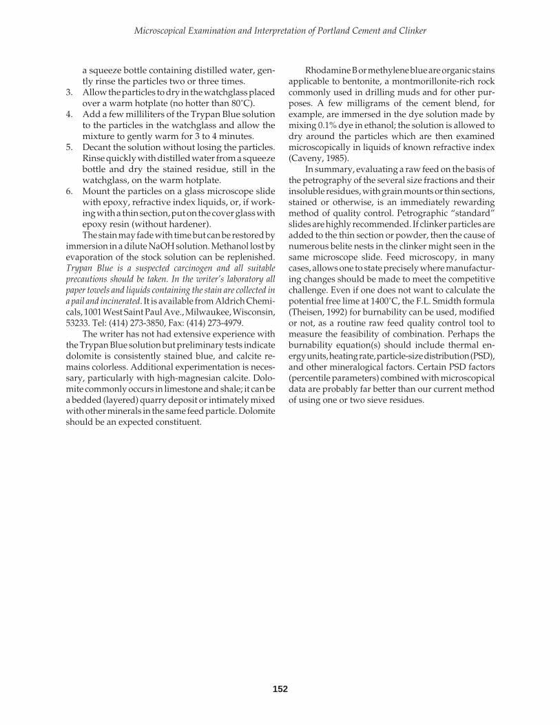
152
Microscopical Examination and Interpretation of Portland Cement and Clinker
a squeeze bottle containing distilled water, gen-tly rinse the particles two or three times.
3. Allow the particles to dry in the watchglass placedover a warm hotplate (no hotter than 80˚C).
4. Add a few milliliters of the Trypan Blue solutionto the particles in the watchglass and allow themixture to gently warm for 3 to 4 minutes.
5. Decant the solution without losing the particles.Rinse quickly with distilled water from a squeezebottle and dry the stained residue, still in thewatchglass, on the warm hotplate.
6. Mount the particles on a glass microscope slidewith epoxy, refractive index liquids, or, if work-ing with a thin section, put on the cover glass withepoxy resin (without hardener).The stain may fade with time but can be restored by
immersion in a dilute NaOH solution. Methanol lost byevaporation of the stock solution can be replenished.Trypan Blue is a suspected carcinogen and all suitableprecautions should be taken. In the writer’s laboratory allpaper towels and liquids containing the stain are collected ina pail and incinerated. It is available from Aldrich Chemi-cals, 1001 West Saint Paul Ave., Milwaukee, Wisconsin,53233. Tel: (414) 273-3850, Fax: (414) 273-4979.
The writer has not had extensive experience withthe Trypan Blue solution but preliminary tests indicatedolomite is consistently stained blue, and calcite re-mains colorless. Additional experimentation is neces-sary, particularly with high-magnesian calcite. Dolo-mite commonly occurs in limestone and shale; it can bea bedded (layered) quarry deposit or intimately mixedwith other minerals in the same feed particle. Dolomiteshould be an expected constituent.
Rhodamine B or methylene blue are organic stainsapplicable to bentonite, a montmorillonite-rich rockcommonly used in drilling muds and for other pur-poses. A few milligrams of the cement blend, forexample, are immersed in the dye solution made bymixing 0.1% dye in ethanol; the solution is allowed todry around the particles which are then examinedmicroscopically in liquids of known refractive index(Caveny, 1985).
In summary, evaluating a raw feed on the basis ofthe petrography of the several size fractions and theirinsoluble residues, with grain mounts or thin sections,stained or otherwise, is an immediately rewardingmethod of quality control. Petrographic “standard”slides are highly recommended. If clinker particles areadded to the thin section or powder, then the cause ofnumerous belite nests in the clinker might seen in thesame microscope slide. Feed microscopy, in manycases, allows one to state precisely where manufactur-ing changes should be made to meet the competitivechallenge. Even if one does not want to calculate thepotential free lime at 1400˚C, the F.L. Smidth formula(Theisen, 1992) for burnability can be used, modifiedor not, as a routine raw feed quality control tool tomeasure the feasibility of combination. Perhaps theburnability equation(s) should include thermal en-ergy units, heating rate, particle-size distribution (PSD),and other mineralogical factors. Certain PSD factors(percentile parameters) combined with microscopicaldata are probably far better than our current methodof using one or two sieve residues.

153
PCA SP030
Photograph 10-3 Thin section of kiln feed containingan abundance of coarse micaceous siltstone (arrows),providing the silica for the clinker and producing auniform distribution of clinker silicates, suggesting theease with which combination can occur with fine-grained, polycrystalline, impure, siliceous rawmaterials. (S#A6871)
Crossed polarsField dimensions = 0.6 mm x 0.6 mm
PHOTOMICROGRAPHS OF PORTLAND CEMENT RAW MATERIALS
Photograph 10-1 Kiln feed in thin section.Multicolored particles are grains of dolomitic limestone(calcite). Gray quartz at lower right, feldspar at upperright. Clinker produced contains an abundance ofbelite nests and periclase. (S#A6869)
Crossed polarsField dimensions = 0.3 mm x 0.3 mm
Photograph 10-2 Feed particles representing theinsoluble residue from acetic acid in a thin sectionwhich is slightly thicker than normal. Gray and yellowquartz, microcline feldspar (arrow), and other silicates.Q
45 = 2.05%, A
K = 5.1%, the latter comprised largely of
finely microcrystalline volcanic rock fragments. Silicatedistribution in the clinker is exceedingly nonuniform,belites are yellow and amber, and strengths are low.(S#A6870)
Partially crossed polarsField dimensions = 0.3 mm x 0.3 mm

154
Microscopical Examination and Interpretation of Portland Cement and Clinker
PHOTOMICROGRAPHS OF PORTLAND CEMENT RAW MATERIALS (CONTINUED)
Photograph 10-6 Thin section of easily burned rawfeed (>45-µm fraction) showing round polycrystallinepetroleum catalyst (upper left), glassy ceramic waste(magenta arrow), quartzite (green arrow), and iron-bearing limestone (yellow arrow). (S#A6874)
Transmitted, plane-polarized lightField dimensions = 0.3 mm x 0.3 mm
Photograph 10-4 Thin section of >125-µmfraction of raw feed showing twinned feldspar (left)surrounded by fine- to medium-crystalline limestone,with ferro-magnesian silicate (hornblende) on right.(S#A6872)
Transmitted, plane-polarized lightField dimensions = 0.6 mm x 0.6 mm
Photograph 10-5 Same as 10-4 but with crossedpolars. (S#A6873)

155
PCA SP030
PHOTOMICROGRAPHS OF PORTLAND CEMENT RAW MATERIALS (CONTINUED)
Photograph 10-9 Same field of view as 10-8 but withpartially crossed polars. (S#A6877)
Photograph 10-7 Same field of view as 10-6 but withcrossed polars. (S#A6875)
Photograph 10-8 Thin section of raw feed, 45- to125-µm fraction, showing pale green glassy slag (left),shale (right), and calcite marble (center). (S#A6876)
Transmitted, plane-polarized light.Field dimensions = 0.3 mm x 0.3 mm

156
Microscopical Examination and Interpretation of Portland Cement and Clinker
PHOTOMICROGRAPHS OF PORTLAND CEMENT RAW MATERIALS (CONTINUED)
Photograph 10-12 Same field of view as 10-11 butwith partially crossed polars. Note quartz and quartziteon left. (S#A6880)
Photograph 10-10 Thin section of easily burned rawfeed (45-µm fraction) composed largely of calcite fossilshells (foraminifera), many of which contain opaquecrystals of pyrite (FeS
2). Chert (microcrystalline quartz)
with iron stain and dolomite at upper right, and largequartz at bottom. (S#A6878)
Transmitted, plane-polarized lightField dimensions = 0.6 mm x 0.6 mm
Photograph 10-11 Raw feed thin section of 45- to 75-µm material stained with a sodium cobaltinitrite-bariumchloride-amaranth solution, revealing potash feldspars(yellow) and calcite (pink to red). (S#A6879)
Transmitted, plane-polarized lightField dimensions = 0.6 mm x 0.6 mm

157
PCA SP030
PHOTOMICROGRAPHS OF PORTLAND CEMENT RAW MATERIALS (CONTINUED)
Photograph 10-15 Thin section of 45- to 75-µmfraction of raw feed stained with a sodiumcobaltinitrite-barium chloride-amaranth solution,showing yellow potash feldspar and pink calcite.(S#A6883)
Transmitted plane-polarized lightField dimensions = 0.3 mm x 0.3 mm
Photograph 10-13 Hard-to-burn silica-rich raw feed inthin section, acetic-acid insoluble residue (>45 µm),showing cleavage on plagioclase feldspar (sodiumaluminosilicate, green arrow), and hornblende (a ferro-magnesian silicate, magenta arrow). Iron-rich particlesare dark brown and opaque. (S#A6881)
Transmitted, plane-polarized lightField dimensions = 0.3 mm x 0.3 mm
Photograph 10-14 Same field of view as 10-13 butwith partially crossed polars. (S#A6882)
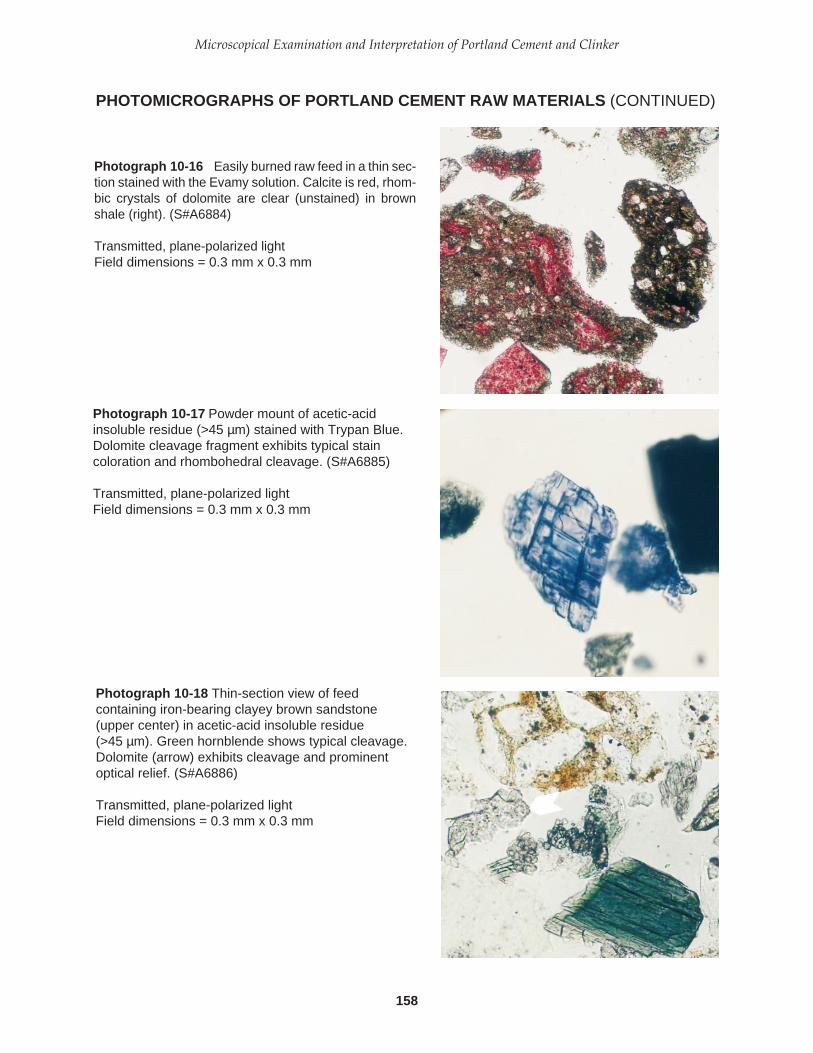
158
Microscopical Examination and Interpretation of Portland Cement and Clinker
PHOTOMICROGRAPHS OF PORTLAND CEMENT RAW MATERIALS (CONTINUED)
Photograph 10-17 Powder mount of acetic-acidinsoluble residue (>45 µm) stained with Trypan Blue.Dolomite cleavage fragment exhibits typical staincoloration and rhombohedral cleavage. (S#A6885)
Transmitted, plane-polarized lightField dimensions = 0.3 mm x 0.3 mm
Photograph 10-18 Thin-section view of feedcontaining iron-bearing clayey brown sandstone(upper center) in acetic-acid insoluble residue(>45 µm). Green hornblende shows typical cleavage.Dolomite (arrow) exhibits cleavage and prominentoptical relief. (S#A6886)
Transmitted, plane-polarized lightField dimensions = 0.3 mm x 0.3 mm
Photograph 10-16 Easily burned raw feed in a thin sec-tion stained with the Evamy solution. Calcite is red, rhom-bic crystals of dolomite are clear (unstained) in brownshale (right). (S#A6884)
Transmitted, plane-polarized lightField dimensions = 0.3 mm x 0.3 mm

159
PCA SP030
PHOTOMICROGRAPHS OF PORTLAND CEMENT RAW MATERIALS (CONTINUED)
Photograph 10-21 Thin section of high-silica shaleparticles in white-cement raw feed. Grain at left haswell-oriented sericite mica flakes; grain on right showsvery finely microcrystalline assemblage of quartz, clay,and mica. (S#A6889)
Transmitted, plane-polarized lightField dimensions = 0.6 mm x 0.6 mm
Photograph 10-19 Thin section of 45- to 125-µm feedshowing brown and pale yellow glassy slag, andmicrocrystalline basalt fragments containing dark iron-oxide minerals (magnetite) and feldspar. Calcitemarble particle below slag and at upper left.(S#A6887)
Transmitted, plane-polarized lightField dimensions = 0.3 mm x 0.3 mm
Photograph 10-20 Acetic-acid insoluble residue inpowder mount of >45 µm fraction in epoxy resin,showing glassy slag particles (lower left) and iron-bearing basalt (top). (S#A6888)
Transmitted, plane-polarized lightField dimensions = 0.3 mm x 0.3 mm
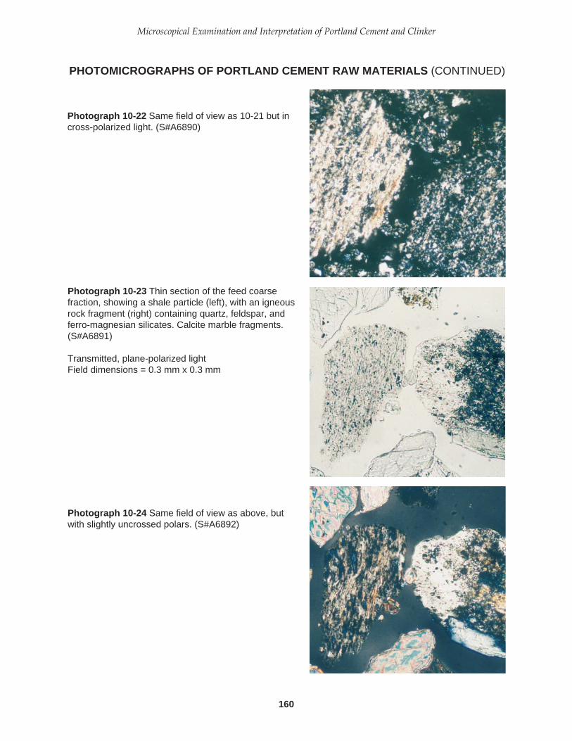
160
Microscopical Examination and Interpretation of Portland Cement and Clinker
PHOTOMICROGRAPHS OF PORTLAND CEMENT RAW MATERIALS (CONTINUED)
Photograph 10-22 Same field of view as 10-21 but incross-polarized light. (S#A6890)
Photograph 10-23 Thin section of the feed coarsefraction, showing a shale particle (left), with an igneousrock fragment (right) containing quartz, feldspar, andferro-magnesian silicates. Calcite marble fragments.(S#A6891)
Transmitted, plane-polarized lightField dimensions = 0.3 mm x 0.3 mm
Photograph 10-24 Same field of view as above, butwith slightly uncrossed polars. (S#A6892)
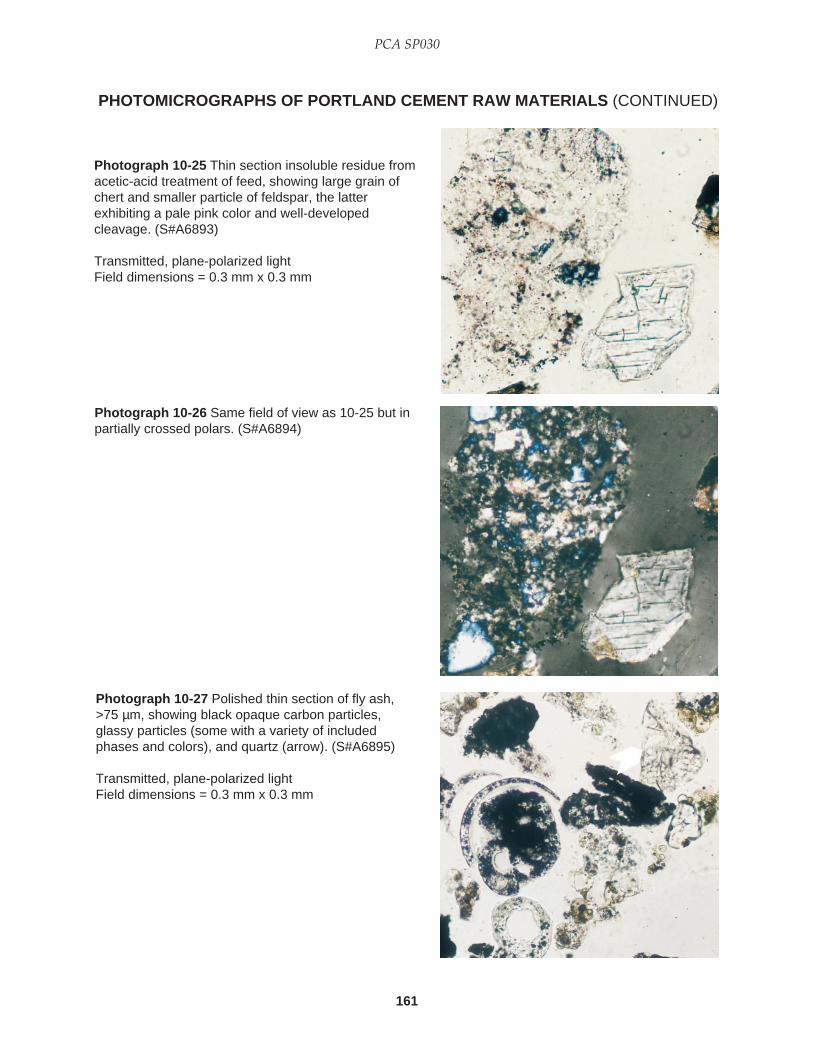
161
PCA SP030
PHOTOMICROGRAPHS OF PORTLAND CEMENT RAW MATERIALS (CONTINUED)
Photograph 10-27 Polished thin section of fly ash,>75 µm, showing black opaque carbon particles,glassy particles (some with a variety of includedphases and colors), and quartz (arrow). (S#A6895)
Transmitted, plane-polarized lightField dimensions = 0.3 mm x 0.3 mm
Photograph 10-25 Thin section insoluble residue fromacetic-acid treatment of feed, showing large grain ofchert and smaller particle of feldspar, the latterexhibiting a pale pink color and well-developedcleavage. (S#A6893)
Transmitted, plane-polarized lightField dimensions = 0.3 mm x 0.3 mm
Photograph 10-26 Same field of view as 10-25 but inpartially crossed polars. (S#A6894)

162
Microscopical Examination and Interpretation of Portland Cement and Clinker
Photograph 10-30 Same field of view as 10-29 butwith crossed polars. (S#A6898)
Photograph 10-28 Powder mount of acetic-acidinsoluble residue, >45µm, showing abundant largequartz grains (multicolored) and rhombohedraldolomite crystals (arrows). Raw feed for whiteportland cement. (S#A6896)
Transmitted light, partially crossed polarsField dimensions = 0.3 mm x 0.3 mm
Photograph 10-29 Thin section of raw feed,centrifuged in epoxy (Campbell, 1986), showing thecoarse fraction at the base of the test tube. Largeshale particle (upper center), sandstone andlimestone, left and right, respectively. (S#A6897)
Transmitted, plane-polarized lightField dimensions = 0.3 mm x 0.3 mm
PHOTOMICROGRAPHS OF PORTLAND CEMENT RAW MATERIALS (CONTINUED)

163
PCA SP030
The suggested format for detailed clinker examina-tion given in this chapter requires more observationthan a “routine” analysis would necessitate. How-ever, answers to many of the questions posed in thesuggested format have not been published, and, there-fore, the outline may point to some needed researchthat may have very practical consequences. For ex-ample, little is known about belite inclusions in alite(their size, abundance, and composition) in relation-ship to burning conditions and raw feed characteris-tics. Crystal size distributions of most of the matrixphases in relation to burning conditions are also poorlyknown. In short, detailed quantitative studies of phasevarieties are needed, not only as subjects of scientificinquiry but also for the purpose of improving thequality and extending the usefulness of portland ce-ment. The format is designed to elucidate the variationwithin and among clinker nodules or fragments.
SUGGESTED FORMAT FOR DETAILEDCLINKER EXAMINATION *
A. Production date and timeB. Examination dateC. Megascopic properties—hardness, color, po-
rosity, shape; note variations in these propertieswithin and between clinkers and establish pre-dominant characteristics; agglomerated or singlenodules.Size variation—if sieving is impractical, estimatethe following, in metric terms, from a randomsample:
modal clinker size—the most frequently occur-ring diameter16th and 84th percentiles—determine whichclinker diameter has 1/6 of the clinker diam-eters larger than itself . . . this is the 84thpercentile diameter on a cumulative percent-
age curve. Next, determine which clinkerdiameter has 1/6 of the clinker diameterssmaller than itself . . . this is the 16th percen-tile diameter. The difference between thesepercentiles includes approximately ± onestandard deviation(s) from the median clin-ker size, i.e., (84th - 16th) ÷ 2 = ± s, assuminga population with a normal size distribution.
D. Microscopical description (powder mount, pol-ished section, polished thin section). Each clin-ker phase is described in this recommendedorder:1. Percentage (state method, such as point
count, line count, etc., if other than estima-tion with comparison charts).
2. Occurrence and distribution pattern—uni-formly, randomly, or patchily distributed;occurrence near or in pores, near certainother phases, clinker core, shell, sharplybounded groups (nests) of crystals, diffuseboundaries, and so on.
3. Orientation of crystals—random or pre-ferred, local or general.
4. Crystal size—mode, extreme range, and gra-dation (estimation of s as described above);unimodal or bimodal; comparison withinand among clinkers. In order to establish aclassification and nomenclature for clinkertexture (that is, crystal size), the followingscheme is proposed, based on the most com-monly occurring alite crystal length:
* Modified after Folk, R.L., Petrology of Sedimentary Rocks,Hemphill Publishing Co., Austin, Texas, 1980, 184 pp.
CHAPTER 11
Recommended Formats and Materials

164
Microscopical Examination and Interpretation of Portland Cement and Clinker
Alite crystal length Descriptive term(in micrometers)
< 10 Extremely finely crystalline10 to 20 Very finely crystalline20 to 30 Finely crystalline30 to 40 Medium crystalline40 to 50 Coarsely crystalline50 to 60 Very coarsely crystalline
> 60 Extremely coarsely crystalline
5. Facial development on crystals—euhedral,subhedral, anhedral; areas of preferentialdevelopment in a single clinker.
6. Contact features—is phase indented by oth-ers, or does it indent its neighbors?
7. Cleavage, fracture, or parting—how manycleavage directions, intersecting at what anglesand parallel to which crystal faces? Aremicrocracks preferentially oriented in the clin-ker? Do they exhibit phase-specific patterns?
8. Zoning and internal structure—note differ-ences in zonal birefringence and refractiveindex (on broken crystals); twinning or crys-tal intergrowths; number of sets of lamellae;lamellar width variations.
9. Refractive index, color, and pleochroism intransmitted light; luster and color in reflectedlight (without etch); characteristics in re-flected light (oil immersion); note variationswithin species.
10. Interference color, birefringence; straight orwavy extinction; biaxial or uniaxial; negativeor positive 2V; dispersion in transmitted light.
11. Etch or stain effects—consistent or variablewithin individual crystals? Within clinkers?Within species?
12. Inclusions—identify and describe each typewith above outline as completely as neces-sary; note size, distribution among and withinhost crystals, and abundance of each.
13. Freshness, alteration products, homogene-ity of decomposition or alteration withinsame species.
14. Definition of species varieties and descrip-tion—for example, raggedy, round, vs. den-dritic varieties of belite or euhedral, largepericlase vs. anhedral, or dendritic periclase;state relative abundance and preferred loca-tions of each.
15. Affinities and antipathies of occurrence—forexample, does alkali aluminate selectivelyoccur in more porous zones or is free limepreferentially associated with periclase?
Figure 11-1. Comparison chart for visualpercentage estimation (after Terry andChilingar, 1955).

165
PCA SP030
Ferrite: Percentage; crystal morphology; association;average crystal size; color, size. Abundance variationswithin and among clinkers.
Alite: PercentageMode =s = (84th-16th) ÷ 2 =Ave. =Apparent birefringence =Etch reactivity variations (specify etch and length oftime). Crystal morphology; crystal surface character-istics (depth of alteration); internal structure;tendency for coarse cannibalism (masses greaterthan 5 times the average alite crystal size); inclu-sions. Size and abundance variations within andbetween clinkers.
Belite: PercentageMode =s = (84th-16th ) ÷ 2 =Ave. =Crystal colors*** in percentages are ______________.Etch reactivity variations; crystal morphologies;internal structure varieties (Types “A,” “B,” or “C”);inclusions; percentages of nests and types of crystalpacking and their percentages; nest boundaries; ifnest crystals are different from others, describeseparately. Crystal size, morphology, and abundancevariations within and among clinkers.
Raw Feed: Determine the weight percentages in the>125-micron and 45- to 125-micron fraction by wetsieving and list particle varieties in order of decreas-ing volume percentages in each by counting at least200 grains. Determine weight percentages of insolubleresidues 20% acetic acid and 20% HCl treatment,calculate difference, and study the >45-micron in-soluble residues, listing volume percentages of eachparticle type or counting same to determine C125, Q45,AK, etc. Describe differences within each fraction. Usestains and refractive index liquids where practical.
16. Age relations—is one phase being replacedor attacked by others; is it euhedral againstothers; formed earlier or later?
The extensive list of observations given aboverequires far more time than a normal investigationwould allow. For practical reasons, the following for-mat is used by the writer.
CLINKER and RAW FEED MICROSCOPY
Project No.:Company:Date:Sample No.:Number of Nodules Examined: Crushed or whole.Nodule granulometry:Mode* =s = (84th-16th) ÷ 2 =Ave. =
Porosity: Low, moderate, high. Porosity distribution(variation) within and between nodules.
Alkali Sulfate**: Percentage; location; association;average size. Size and abundance variations in andamong clinkers; varieties and individual abundances,if possible. Determine varieties and percentages withXRD.
Periclase: Percentage; crystal morphology; averagecrystal size; percentage larger than 15 microns; asso-ciation. Size and abundance distribution in andamong clinkers.
Free Lime: Percentage; crystal morphology; averagecrystal size; packing; association. Size and abundancedistribution in clinkers. Note amount of epezite inKOH-sugar solution residue.
Aluminates: Percentage; varieties and crystal mor-phologies; association; average crystal size. Size varia-tions in and among clinkers. Matrix percentage anddistribution; aluminate/ferrite ratio, ratio variationswithin and among clinkers. General texture of thematrix (finely crystalline = less than 2.0, mediumcrystalline = 2 to 4, and coarsely crystalline = greaterthan 4 microns), and textural variation within andbetween nodules. Note and describe occurrences ofaluminates other than C3A or (N,K)C8A3. Salicylic acidresidue can be used to concentrate matrix phasesfacilitating refractive index determination.
* Crystal size measurements in microns, nodule size in milli-meters. “Mode” is most frequently occurring size; 16th and84th percentiles refer to estimated points on an imaginarycrystal- or particle-size curve, the difference divided by twois an estimate of one standard deviation (s) on each side ofthe median. “Ave.” = (“mode” + 84th + 16th percentiles) ÷ 3.KOH-sugar extraction facilitates determination of alite bire-fringence and belite color.
** Phase abundances are estimated volume percentages unlessotherwise noted.
*** Crystal color scale: 4=clear, 3=pale yellow, 2=yellow, 1=am-ber; crystals with abundant dotlike products of exsolutionare ranked as 1; estimate the percentages, or determine bycounting at least 200 crystals.

166
Microscopical Examination and Interpretation of Portland Cement and Clinker
Note: Record observations of nodule color variations,and other unusual occurrences such as refractoryfragments, weathered clinkers, and clinker noduledisintegration.
EXTRACTION TECHNIQUES FORCONCENTRATION OF CLINKERSILICATES AND MATRIX
Removal of the matrix phases (aluminate and ferrite)and concentration of the silicates in the residue usinga warm potassium hydroxide-sugar solution greatlyfacilitates the observation of belite color and determi-nation of apparent birefringence of alite. The proce-dure given below is a modification of that presentedby Guttridge (1979) of the Cement and Concrete Asso-ciation in the United Kingdom. Routine use of theKOH-sugar extraction technique is highly recom-mended. Saini and Guilani (1995) emphasize the KOH-sugar extraction method for XRD analysis and micros-copy of clinker, illustrating the close similarity of thedata. Indeed, the present writer always combinespolished section examination in reflected light withpowder studies in transmitted light.1. If a clinker sample is to be subjected to the
extraction, a random sample of 1- to 2-mmcrushed clinker particles, taken from the samefraction as previously prepared for polished sec-tion examination, is further crushed in a mortarand pestle until all the subsample passes a 75-µmscreen (No. 200 mesh). If a cement is to be treated,a random sample of approximately 10 grams issieved to produce the 45- to 75-µm fraction (325to 200 mesh); particles left on the 75-µm screencould be further crushed to pass the screen or,perhaps, studied microscopically to determinebelite nest percentage. Sieving, however, is anoptional step; the main benefit is that it providesa uniformly sized powder promoting a relativelyuniform level of focus by removing “boulders”that may interfere with examination and particlemanipulation. If sieve contamination is a likelyproblem, one can use disposable nylon with theproper mesh opening. Wet sieving with isopropyl alcohol pro-duces a dust-free powder and dries quickly.Some workers prefer to treat the sample withoutsieving or washing, thus wet sieving is also con-sidered optional.
2. Place the dried powder in a small labeled vial orother suitable storage container.
3. On a 125-mm diameter, heavy duty watch glass orsmall beaker (200 mL) placed on a ceramic triangleon a hot plate, add approximately 10 mL of the
KOH-sugar solution (10 grams of KOH + 5 gramsof sugar + 20 mL deionized water). The liquidtemperature for digestion should be approximately80˚C. This solution is extremely caustic and properlaboratory safety precautions such as eye protection,apron, and rubber gloves are recommended.
4. Add a few milligrams of the clinker or cement tothe warm liquid and stir with a glass rod occa-sionally or use a swirling motion to distribute theparticles.
5. After warming for approximately 15 to 20 min-utes, remove the beaker from the hot plate, adda few milliliters of distilled water to reduce vis-cosity, and decant the liquid. Withdraw the re-maining liquid with the edge of a paper towel.
6. Rinse the wet residue with a stream of deionizedwater from a squeeze bottle, decanting the liq-uid. Do this three times within a 3-minute inter-val. Do not be concerned with traces of a precipi-tate that may form or tiny crystals that may growon the silicate particles. Withdraw the remainingliquid with the edge of a paper towel.
7. Flood the residue with acetone or isopropylalcohol and decant the liquid. Do this three timeswithin a 3-minute interval.
8. Allow the residue to dry on a hotplate and trans-fer to a labeled vial for storage. An artist’s paint-brush and slick paper (old photographic paper)facilitates this transfer.
9. Prepare a powder mount, using a liquid with arefractive index of approximately 1.715, for ex-amination in transmitted polarized light at 400X.The microscope should be equipped with a day-light blue filter over the light source. Light inten-sity settings and the substage aperture diaphragmshould be constant from sample to sample.Belite crystals (nested or single) and whole alite
crystals are amazingly easy to find and observe withthis technique. One is able to count the number ofbelite nest fragments in the powder mount, possiblyrelating these data to coarse quartz percentages in theraw feed. At liquid boiling temperatures, however,most of the belite nests commonly lose their integrityand are dissolved into single crystals. Thus the pro-posed procedure is not designed to destroy the belitenests and, therefore, one can easily see the preferentialcolors that nested belite commonly exhibits comparedto solitary belite.
For details of crystal counting to determine belitecolor percentages and a discussion of some of theproblems involving color observations, see Campbell(1994) and parts of Chapter 6. Alkali sulfate, epezite,periclase, some free lime, and other phases are presentin the residue.

167
PCA SP030
For removal of the silicates and concentration ofthe matrix phases, a solution of 30 grams salicylic acid,added to 250 mL methanol, is made, and a few millili-ters of the liquid are placed in a beaker or watch glass.The clinker or cement particles (sieved or otherwise)are added to the container and the mixture placed on awarm hotplate (80°C) for approximately 30 minutes.The methanol lost by evaporation can be replenishedperiodically. Decant and withdraw the remaining liq-uid with paper towels and rinse the residue with metha-nol or acetone three times over a 3-minute interval andallow the preparation to dry on the hotplate. Gatherand store the particles as described above, and studywith a polarizing-light microscope, keeping in mindthat the powder mount may also contain phases inaddition to aluminate and ferrite. Fragments of tightlypacked belite nests may remain but can perhaps beremoved by boiling in the methanol-salicylic acid solu-tion instead of merely warming.
QUANTITATIVE MICROSCOPY
Determination of the percentages of clinker phases canbe accomplished by (a) visual comparison with known(measured) clinker standards (Long, 1982a), (b) visualcomparison with percentage diagrams (Figure 11-1), (c)point counts, or (d) linear traverse. Point counts entailthe identification and recording of the phase undercross-hair intersections or dots in an eyepiece reticle.
Hofmänner (1973) has clearly discussed the prob-lem of accurate determination of phase abundance andrecommends a point count of at least 4000 points on apolished section of epoxy-encapsulated, crushed clin-kers, using a 25-point grid reticle placed in the micro-scope eyepiece. According to Hofmänner, a competentmicroscopist can count approximately 1000 points perhour with a distance between points approximatelyequal to the average diameter of the crystals. Thefollowing equation was given by Hofmänner (1973) toestimate the measuring error,∆, in point counting:
∆ = −
2.0235P(100 P
n(Eq. 14)
where P = percent of points representing a givenphase, and
n = total number of pointsThis equation indicates that the measuring error
changes only slightly after 4000 points have beentallied.
Semiautomatic tallying devices (multiple channelcounters) and automatic mechanical microscope stagesare available to streamline the counting and make itless time-consuming. Voice-activated data recorderswith simple statistical calculations should, theoreti-cally, make quantitative microscopy much easier by
permitting an almost continuous eye-to-eyepiece rela-tionship for the observer. Software for geologic point-count data manipulation are presently on the marketand could, perhaps, be modified for clinker (or rawfeed) use. A second person to keep a tally sheet is veryhelpful.
Confidence in using percentage diagrams for abun-dance estimates could be strengthened by combiningpoint counts on the same clinkers until the microscopistfeels that his or her visual estimates are sufficientlyaccurate, that is, within a tolerable range of error. Fornormal clinker investigations, however, a simple esti-mate, either based on comparison with point-countedstandards or percentage diagrams, will often suffice.Corroboration by XRD analysis can be quite reward-ing, especially with computer-integrated systems.
Midgley and Dharmadhikari (1964) describedmethods of point counting polished sections of clin-kers, using an HF vapor etch and 1000 to 2000 points.These authors stated that the standard deviation of thealite and belite weight percentages were estimated at1.0 and 1.5, respectively, and that the microscopicalmethod is as accurate as that obtained from Boguecalculations and better than that from X-ray diffraction.
Comparisons of statistical analyses of phase per-centages determined microscopically by various work-ers, laboratories, and techniques have been presentedby the Chemical Commission of the Technical StudiesCommittee of the Cement Industry (1978), a Frenchorganization. The methods and principal conclusionsfrom their analyses are:
1. The sample is made from 5 kg of clinker, crushedin a jaw crusher with a gap of 2 mm and screenedon a 150-µm sieve. The fraction larger than 150µm is used.
2. A polished section is etched with an ammoniumnitrate solution in a mixture of water and alcoholto reveal the silicates, followed by a nital etch,which in turn is followed by a sodium hydroxidesolution etch to reveal the interstitial phases.
3. Magnification is adapted to the dimensions to bemeasured, with 4000 points tallied. Chemical dis-solution of clinkers with salicylic acid to selec-tively remove silicates and free lime, followedby removal of C3A by sugar-water, results in afairly good microscopic correspondence with thesilicates but poor correlations with aluminatesand ferrite.
4. Alite and belite percentages determined by mi-croscopy are generally higher and lower, respec-tively, than the values calculated by the Bogueequations. Major errors in microscopical percent-ages of matrix phases are mainly due to smallcrystal sizes.
168
Microscopical Examination and Interpretation of Portland Cement and Clinker
Ono (1995) presented a series of correction factorsin the calculation of phase percentages by the Bogueequations. The factors involve: minor components, solidsolution of C3S and C2S, solid solution of C6A2F-C4AF,and glass. Taylor (1990) also provided formulas forcorrecting the Bogue calculations.
Chromy (1983), utilizing a 2000-point count on 22-mm diameter polished sections of a sieved crushedclinker sample, demonstrated the usefulness of themicroscope in determining the mineralogical composi-tion of clinker, the data from which were related math-ematically to clinker and raw mix composition, andcement strength. He concluded, “If conversion con-stants linking the equilibrium clinker composition andstrength are determined, it is not necessary to carry outthe quantitative phase analyses of the clinker produced.Monitoring the free lime content will suffice.”
Chromy (1992) described his quantitative micro-scopical method of clinker quality control in Czechoslo-vakia, using both powder mounts (Ono’s technique) andpolished sections, the latter made and analyzed in whatappears to be less than 30 minutes. Chromy’s procedureis: (1) The encapsulation mold, with its floor just coveredwith 0.5- to 1.0-mm size particles of crushed clinker isheated to approximately 110˚C and the epoxy intro-duced in drop fashion. The initial epoxy quickly hardensin a few minutes, after which the remaining epoxy isadded, producing a frothy mass which also hardens andcompletes the encapsulation. After grinding and polish-ing the bottom of the encapsulation, the areas of alite,belite, and matrix are estimated at 100X, followed byestimation of the matrix phase percentages at 400X. Themicroscopist, in regularly scheduled intervals, checksmainly for deviations from optimum target composi-tions, indicating changes in the production process.Free-lime percentage is given major emphasis in qualitycontrol and for this parameter free-lime “aggregates”are counted microscopically in 11 fields of view, eachfield having a diameter of 2.2 mm. The free lime inweight percent of the clinker is then calculated by divid-ing the number of aggregates by the number of fields,providing a determination said to be as good as that bychemistry. Chromy stated that any increase in the levelof free lime may be due to underburning, high limesaturation factor, high silica modulus (deficient liquidphase), feed fineness too low, or insufficient homogeni-zation of the raw mix (which can be recognized by anuneven distribution of the alite and belite). “Operationalmicroscopy,” as Chromy calls it, can replace the tradi-tional method of determining liter weight and free lime.
Linear traverse methods, which record crystal chordlengths and calculate volume and weight percentagesas well as specific surfaces of alite and belite, haverecently been used to study clinker thermal history and
grindability (Scheubel, 1983). Quantitative microscopy,like that in the previously mentioned paper, is greatlyneeded in clinker analysis.
Hicks and Dorn (1982) have shown the practicalityof using a computer to calculate correlation coefficientsfrom Ono test data, stating, “The computer remains apowerful tool for drawing correlations from masses ofdata and discovering new paths of usefulness as theprogram matures.”
Statistical methods were used by O’Kelly and For-tune (1983) to relate microscopically determined silicatepercentages and clustering tendencies to grindability.
Marciano, Zampiere, and Centurione (1987) gaveemphasis to quantitative (statistically designed) clinkermicroscopy, using an eyepiece micrometer scale for phaseabundance determination. These authors summarizedthe microscopical differences between a well-granulatedclinker and one with an excess of fines, the latter said tobe due to poor raw material grinding and blending, anduse of coarsely ground high-ash (35%) coal.
Hargave and others (1983) quantitatively related(a) phase assemblage (weight ratios), (b) stabilizationof phase modifications, (c) silicate crystal size, (d) sili-cate crystal morphology, and (e) clustering of phases totype of burning process (wet, semidry, and dry). Leastsquare linear regression techniques established somegeneral trends in relation to compressive strength andshowed the negative effect of phase clustering (Hargaveand others, 1985 and 1988).
The procedure of microscopically superimposing agrid of lines or curves on a microscopical field of viewand counting the number of points, averaging for aselected number of fields, has been standardized byASTM Subcommittee Task Group C1.23.02 for use inpoint counting of portland cement clinker polished sec-tions, the present author writing the original draft of theprocedure for the Task Group. The ASTM designationis C 1356-M, titled Standard Test Method for the Quantita-tive Determination of Phases in Portland Cement Clinker byMicroscopical Point-Count Procedure.
Weigand (1994) reported the point-count results ofthe ASTM microscopy task group on one of the Stan-dard Reference Clinkers supplied by the National Insti-tute of Standards and Technology (Gaithersburg, Mary-land). Compared to the Bogue calculations, the micro-scopical data are roughly 5% higher for alite, 5% lowerfor belite, 4% lower for C3A, and 0.5% lower for ferrite.It was further shown that 3000 points per sample wouldprovide sufficient data for statistical acceptance of port-land cement clinker polished sections.
The National Institute of Standards and Technol-ogy (NIST) offers a set of Standard Reference Clinkersfor phase abundance. Analysis of these clinkers bySEM, light microscopy, and QXRD is found in Stutzman
169
PCA SP030
and others (1989). Purchase and study of these Stan-dard Reference Materials is strongly recommended.
MICROSCOPICAL EQUIPMENT,SUPPLIES, AND THIN SECTIONSERVICES
Equipment needed for microscopy in a cement plantmay range from only a polarized-light microscoperequired for powder mount analysis to sawing, grind-ing, and polishing equipment necessary for thin-sec-tion and polished-section study. Two somewhat ideal-ized lists of equipment are given in Table 11-1. The“Economy” column in the table contains only the mini-mum equipment for powder-mount study and pol-ished-section examination. The other column also con-tains items for preparation of thin sections.
Refractive-index liquids are normally used in trans-mitted light. However, some liquids when continuousbetween the polished section and the oil-immersionobjective lens, utilizing reflected light, reveal an amaz-ing detail, especially in the clinker matrix. Cedarwoodoil (n = 1.51) and a 100X specially designed objective arerecommended for oil-immersion reflected-light stud-ies. For use in transmitted light, a set of refractive-indexliquids, ranging from n = 1.40 to 2.00, will suffice formost examinations. Many of these liquids are toxic andadequate ventilation is required.
A list of common permanent mounting media isgiven in Table 11-2, followed by names and addressesof some of the companies specializing in commercialthin-section preparation (Table 11-3).
The use of X-ray diffraction (XRD) data can clearlybe supportive to microscopy in almost all materialsinvestigations. One obvious advantage of XRD analysisis that it is a reliable mode of identification and quanti-fication for almost all of the major phases commonlyseen in raw feed, clinker, and cement. However, XRDanalysis suffers one major disadvantage: it cannot tellyou where, in the examined mass of clinker, the belite islocated or how the belite is related to alite. XRD analysiscan indicate the presence of belite and, with somecalibrated standards, the amounts of belite polymor-phs, but only the microscope can tell you that the beliteoccurs mostly as decomposition of alite crystals or thatthe belite occurs only as inclusions in alite. XRD analy-sis may indicate the presence and quantity of more than
* Most of the photomicrographs in this publication were customprinted by Doug Goddard, Gamma Inc., Chicago, Illinois.
** Manufacturers and products are listed for reference or to assistin locating various products; this does not imply PortlandCement Association endorsement or approval.
trace amounts of free lime, but only microscopy willtell you that the free lime occurs within alite or that thefree lime is associated with periclase. The human eyecan microscopically detect phases that, because of theirsmall percentage or amorphous character, are not de-tected by XRD. XRD analysis, therefore, should beused in a corroborative manner with microscopy.
Photography * is virtually essential in providingpictorial evidence for the interpretations drawn frommicroscopical examination. A Polaroid-type** camera(large format) is most convenient, producing photo-micrographs quickly and easily for reports. For pro-jection screen presentation, a 35-mm color slide is,thus far, unexcelled. Films such as Kodak Kodacolor II(VR-100), Ektachrome 64, 64T, and VT1000, AGFA-RSX 100, and AGFA 100 have been used satisfactorilyby the writer for color photographs. Tungsten 160 filmis recommended by Dorn (personal communication,1985); this slide film requires no filters. Ilford Pan Ffilm, in the author’s opinion, is excellent for black andwhite photographs.
One of the most effective means of quickly con-veying microscopical information is through the useof a video camera and monitor with which one canshow a wide range of clinker features while the audi-ence, in a sense, participates in observation and analy-sis. As a teaching tool, the video system is unsur-passed. The video camera and monitor, combinedwith videotape and videoprint attachments, providesa permanent visual data base for clinker comparisons.And lastly, the computer, having already been provenadept at data analysis, may find routine application inimage and phase analysis, storing the visual dataacquired during an automatic linear traverse of apolished and suitably etched section on CD-ROM orother storage devices. Such information can be trans-mitted in “real time” via the Internet to waiting com-puters in, for example, a cement-plant laboratory.
Image analysis and description of its method-ological problems, discussed in papers by Märten,Strunge, and Knöfel (1994), Theisen (1997), andAnwander (1998), are quite instructive. These authorsrecommend the use of HF vapor as an etchant and realcolor processing to determine phase percentages (alite,belite, and matrix). Research by the present writersuggests the feasibility of the technique.

170
Microscopical Examination and Interpretation of Portland Cement and Clinker
Microscopical Equipment Suppliers
Buehler Ltd. McCrone Accessories &41 Waukegan Road ComponentsLake Bluff, IL 60044 850 Pasquinelli DriveTel: 847-295-6500 Westmont, IL 60559-5531Fax: 847-295-7979 Tel: 800-622-8122
Fax: 630-887-7764
Fryer Company Inc. Microtec Engineering Lab11177 East Main Street P.O. Box 636Huntley, IL 60142-7147 Clifton, CO 81520Tel: 847-669-2000 Tel: 970-434-8883Fax: 847-669-2056 Fax: 970-434-4747
Hacker Instruments, Inc. Wards Natural ScienceP.O. Box 657 Establishment, Inc.Fairfield, NJ 07006 P.O. Box 1712Tel: 973-226-8450 Rochester, NY 14603Fax: 973-808-8281 Tel: 800-962-2660
Fax: 800-635-8439
South Bay Technology, Inc. Gilson Company, Inc.1120 Via Callejon P.O. Box 200San Clemente, CA 92673 Lewis Center, OH 43035Tel: 800-SBT-2233 Tel: 800-444-1508Fax: 714-492-1499 Fax: 800-255-5314
Struers, Inc.810 Sharon DriveWestlake, OH 44145
Table 11-1. Microscopical Equipment andSuppliers*
Equipment
Complete Lab Economy LabTrim saw (150-mm diam., oil
coolant)1
Table-top saw with small Table-top sawflanges and appropriatechucks
3 Grinder-Polishers with extra 1 Grinder-Polisher with 2wheels and MinimetTM extra wheels or MinimetTM
(Buehler), the latter withslide holder for thin sections
2 Glass plates (300x300 mm) 2 Glass plates (300x300 mm)
Vacuum impregnatorEpoxy and hardener and Epoxy and hardener and
polyethylene cups (several polyethylene cupsvarieties of each)
Cyanoacrylate adhesive Cyanoacrylate adhesive(Super GlueTM) (Super GlueTM)
Slide warmerPolaroidTM and 35-mm cameras, PolaroidTM camera
video recorder, monitor,video printer
Hot plate
Thin-section grinder2
Thin-section cut-off saw2
Oil coolant (lapping oil)1,2
Stereomicroscope
Polarized-light microscope Polarized-light microscope
Sénarmont compensator Sénarmont compensatorReflected-light (metallo- Reflected-light (metallo-
graphic) microscope graphic) microscopePetrographic slides Petrographic slides
(46x24 mm) (46x24 mm)Diamond pencil or electric Diamond pencil or electric
engraver engraver
Cover glasses Cover glasses (several sizes)
Refractive-index liquids Refractive-index liquids
Mortar and pestle Mortar and pestleAlcohol (isopropyl) and spray Alcohol (isopropyl) and spray
bottles bottles
Propylene glycol Propylene glycol
Acetone
Stage micrometer Stage micrometer
Polishing cloths and powders Polishing cloths and powdersAdhesive-backed grinding Adhesive-backed grinding
papers papers
Sieves, 76-mm diam. Sieves, 76-mm diam.
Hot air blower Hot air blower
Calculator CalculatorVials and caps (15 mL) for Vials and caps (15 mL) forpowders or plastic bags powders or plastic bags
Sample jars and caps Sample jars and caps
Steel file (fine) Steel file (fine)
* Manufacturers and products are listed for reference or toassist in locating various products; this does not implyPortland Cement Association endorsement or approval.
1 Propylene glycol or mineral oil may be substituted forlapping oil. Mobil DTETM FM 32 is available from:
Mobil Oil Corp.Products and Technology Dept.3225 Gallows Rd.Fairfax, Virginia, USA 22037MSDS Fax: 800-662-4524, Tel: 703-849-3265
2 For thin-section preparation

171
PCA SP030
Table 11-2. Permanent Mounting Media
Canada Balsam Resin , index of refraction n = 1.537, andLakeside 70 (a synthetic resin, n = 1.54) available from mostchemical and petrographic supply houses.
Meltmount , n = 1.539, 1.582, 1.662, 1.704 for grain mounts:Cargille Laboratories, Inc.Cedar Grove, NJ 07009Tel: 973-239-6633Fax: 973-239-6096
McCrone Accessories & Components850 Pasquinelli DriveWestmont, IL 60559-5531Tel: 800-622-8122Fax: 630-887-7764
Quickmount, a medium-viscosity resin mixed at 2 partspowder to 1 part liquid, by volume, for grain mounts andclinker encapsulations:
Fulton Metallurgical Products Corp.P.O. Box 118A, Saxonburg Blvd.Saxonburg, PA 16056Tel: 724-265-1575Fax: 724-898-3192
Epoxy Resins *
Araldite 506 Resin with Hardener HY-2964, low-viscosity,mixed at 2 parts resin to 1 part curing agent for n = 1.56:
Ciba-Giegy Corp.Mktg. Resins DivisionBrewster, NY 10509Tel: 800-222-1906Fax: 914-785-3477
Epoxide Resin with Hardener and Epo-Kwick : mixed at 5parts resin to 1 part hardener, by weight, for n = 1.565; orEpo-Thin , a low viscosity resin mixed at 10 parts resin to 3.6parts hardener:
Buehler Ltd.41 Waukegan RoadLake Bluff, IL 60044Tel: 847-295-6500Fax: 847-295-7979
Struers Epofix and Hardener , a low-viscosity medium mixedat 9 parts resin to 1 part hardener by weight (8:1 by volume),for n = 1.57:
Struers Inc.810 Sharon DriveWestlake, OH 44145Tel: 800-321-5834Fax: 440-871-8188
Spurr Resin (soluble in xylene) with four-part kit:Ladd Research Industries Inc.P.O. Box 901Burlington, VT 05401Tel: 503-253-2843
Epo-Tek 301 , low-viscosity, mixed at 4 parts resin to 1 parthardener for n = 1.56:
Epoxy Technology Inc.14 Fortune DriveBillerica, MA 01821Tel: 978-667-3805Fax: 978-663-9782
* For thin sections, whole grain mounts, clinker impregnations,and encapsulations.
Bubble pack (Epo-Tek 301):APS, Inc.P.O. Box 31103 Foster St.Peabody, MA 01960Tel: 800-222-1117Fax: 978-532-8901
Regular Setting Epoxy (Black Label, 45 min., in small bubblepackages for mounting specimens on glass slides for thinsectioning, n = 1.56):
Hardman, Inc.Belleville, NJ 07109Tel: 973-751-3000Fax: 973-751-8407
Table 11-3. Commercial Thin-Section Makers
American Petrographics, Inc. 40 Appletree LaneRoslyn Heights, NY 11577Tel: 516-625-9162Fax: 516-625-5804
Balsam Petrographics7611 South Springbook Dr.West Jordan, UT 84084Tel: 801-562-2570
Burnham Petrographics846-1 South Myrtle Ave.Monrovia, CA 91016Tel: 800-772-3975Fax: 626-359-1811
D.M. OrganistPetrographic LabP.O. Box 176Newark, DE 19711Tel: 302-368-5361Fax: 302-453-1988
Marathon Oil Co.7400 South BroadwayLittleton, CO 80122Tel: 303-794-2601Fax: 303-794-1720
Mineral Optics LabP.O. Box 828Wilder, VT 05088Tel: 802-295-9373Fax: 802-295-7540
National PetrographicService, Inc.5933 Bellaire Blvd., Suite 108Houston, TX 77081Tel: 713-661-1884Fax: 713-661-0625
San Diego Petrographics27118 North BroadwayP.O. Box 3615Escondido, CA 92026Tel: 760-749-9272Fax: 760-751-1772
Spectrum Petrographics, Inc.499 Dillard Gardens Rd.Suite 2Winston, OR 97496Tel: 800-625-2476Fax: 541-679-5173
Struers Inc.810 Sharon DriveWestlake, OH 44145Tel: 800-321-5834Fax: 440-871-8188
Texas PetrographicService, Inc.15608 South Brentwood,Suite DChannelview, TX 77530Tel: 281-862-0666Fax: 281-862-0777

172
Microscopical Examination and Interpretation of Portland Cement and Clinker

173
PCA SP030
The industrial application of the microscopical studyof portland cement and clinker is comprised of severalfundamental and interrelated parts: (a) data-gather-ing, consisting of phase identification, description ofthe phases and their mutual arrangements, measure-ment of crystal sizes, and estimation of phase abun-dances; (b) analysis, encompassing the correlation ofmicroscopical data with raw-feed characteristics, burn-ing conditions, and cement performance with andwithout admixtures; and (c) prediction of clinkergrindability, cement performance, and, perhaps mostimportantly, the formulation of microscopical criteriafor maintaining optimum kiln conditions.
As an economical and rapid method to control thequality of portland cement, the value of routine clinkermicroscopy should be an inescapable conclusion fromthe numerous observations and interpretations givenon previous pages. Quality control of clinker withoutmicroscopy of raw feed, in the writer’s opinion, is lessthan adequate. Profound cause-effect relationships ex-ist between the raw feed/particle size distribution,energy required for grinding and burning, clinker qual-ity, and cement performance. Visually appreciating thecharacteristics of raw feed via microscopical examina-tion gives additional comprehension to quality control.
“Standard” samples of clinker, cement, and rawmaterials, studied microscopically, with the results ofchemical analysis and x-ray diffraction, form the database for subsequent comparisons. Study of acetic-acidresidues is strongly recommended. “Half-sections” canreplace thin sections, thus saving much time.
A choice between reflected-light or transmitted-light techniques for plant use may, of necessity, bemade on the basis of personal ease of application,tradition, equipment availability, or other reasons. Inthe writer’s opinion, a combination of the two modes ofanalysis is best. Reflected-light observations of pol-ished sections of whole or crushed clinkers from the
modal size class is recommended for silicate crystalmorphology, size, and internal structure and for ma-trix and void phase descriptions. Transmitted-lightobservation of powder mounts, half sections, or thinsections is best for belite colors and apparent birefrin-gence of alite. The potassium hydroxide-sugar solu-tion for extraction of the matrix and concentration ofthe silicates makes transmitted-light microscopy easyfor clinker and cement.
With quickly setting epoxy resins or similar mate-rials, such as cyanoacrylate ester (Super Glue™), andmodern semiautomatic grinding and polishing equip-ment, polished sections can be made within a fewminutes, while an alcohol-washed, sieved clinker pow-der, mounted in refractive-index oil, is studied.
Ono’s theory, on which the “Ono Method” isbased, succinctly set forth in 1981 by Ono (pp. 200-204)and restated in 1995, appears to have a wide andgrowing acceptance, judging by the numerous re-search reports by Asian and South American micros-copists and the increasing use of the method in NorthAmerica. Whether called the “Ono Method” or not, theprincipal variables in clinker quality control are maxi-mum temperature, time at high temperature, rates ofheating and cooling, and the nature of the raw feed.
The Ono method, however, is not the only tech-nique of kiln control through microscopy, nor is it acomplete analysis. The results of transmitted-lightmicroscopy using the Ono method are almost alwaysfortified by reflected-light observations of polishedsections. One must be proficient, therefore, in pow-der-mount and reflected-light microscopy to gain maxi-mum benefit with Ono’s Method. Proficiency is devel-oped only by diligent practice (“eye-training”), adher-ing to the methodological habits of patience and per-severance.
Above all, when examining anything microscopi-cally, avoid giving undue importance to rare occur-
CHAPTER 12
Conclusions

174
Microscopical Examination and Interpretation of Portland Cement and Clinker
rences. Always pause when about to make an inter-pretation and ask “Is this observation characteristic(typical, common) for most of the sample? Does theobservation represent a significant, but minor, portionof the sample, or merely a rare occurrence?” It hasbeen said that one can find “almost anything” inclinker. Therefore, be constantly aware of a normaltendency to exaggerate the minutiae.
Now that phase analyses with electron micros-copy are available, one might foresee a routine, some-what automated microscopical basis for quality con-trol. Computer programs and equipment for automat-ing simultaneous microscopical and chemical analy-ses of polished sections do not appear to be beyondour reach and may, indeed, already be employed on aday-to-day basis in some plants. Application of thecomputerized scanning electron microscope andchemical analysis via energy dispersive x-ray wasdemonstrated by Diamond and Olek (1990) for acement. The techniques were suggested to be appli-cable to supplementary cementitious materials,blended cements, and fly ash. However, the utility ofcomputer-generated data, like all data, is only as goodas the quality of the interpretations. Consequently, themicroscopist should continue to serve in a role ofobjective verification, using the finely honed tech-niques of observation and inference to relate causeand effect. The value of x-ray diffraction can hardly beunderstated. XRD and microscopy combined are liketwo sides of the same coin.
Unfortunately, some of the observations and in-terpretations presented in Chapter 7 (“MicroscopicalInterpretation of Clinkers”) do not appear to befounded in systematic experimental design or statisti-cal analysis. Statistical measures to determine thedegrees of correlation and association of the observa-tions, and their relationship to the various physicaland chemical causal factors of the production process,are essential and urgently needed for several veryimportant reasons:1. To quantify microscopical data in order to re-
move as much subjectivity as possible;2. To strengthen the science of clinker and cement
microscopy in general, that is, to fortify thefoundation with statistical rigor; and
3. To enable the microscopist to communicate pre-cisely with others who are interested in qualitycontrol at the cement plant.Little has been said in the present publication
regarding these specific operational modificationsbecause of the wide variety in types of kilns, and thelarge number of possible equipment changes that maybe necessary to modify burning conditions. However,a few examples can be cited:
Of major importance in future work is the quanti-fication and statistical treatment of microscopical datafrom systematic investigations. Results of an exten-sive statistical study involving 754 clinker samplesover a period of approximately two years to developa database were described by McKenzie (1991). Spe-cific changes in the microscopy were related to equip-ment variations, failures, and other process fluctua-tions. For example, a drop in alite birefringence wasrelated to inefficient coal mill grinding, resulting in areduction of flame temperature. A partial blockage ina primary air duct, due to a snowman in the firinghood and cooler throat, led to an oxygen deficiency,reducing conditions, and a decrease in the burningzone temperature, indicated by lower birefringence ofalite and high ash values. Cariou, Ranc, and Sorrentino(1988) utilized a statistical computer program to ana-lyze the microscopical and chemical data from morethan 60 clinker samples representing many methodsof pyroprocessing. As a result, after determination ofthe chemical composition of the raw material anddefinition of some of the burning-condition param-eters, a clinker mineralogy could be predicted andsubsequently checked in actual production.
As a result of data from powder-mount study andpolished-section examination, Prout (1985) recom-mended the following production process changes:location of burner pipe, feed rate, primary air, and theintergrinding of gypsum with kiln feed so as to pro-duce a molecular sulfur to alkali ratio of not less than0.8. Cement quality greatly improved after the pro-posed changes were made, providing a clear-cut illus-tration of the successful application of the microscopeto cement quality problems and, no less importantly,establishing support from operational personnel. Fordetails concerning microscopical effects of changingburner pipe positions, the reader is referred to a paperby McKenzie (1989a).
Other recommended equipment changes relatedto the improvement of clinker quality can be found inpapers by Hansen (1983) and Miller (1978). Jany andLove (1993) presented microscopical data correspond-ing to specific changes in flame profile, initial cooling,cooler bed depth, and I.D. fan, in a 158.6-meter, dry-process kiln.
Quality control of cement using microscopy findsdaily use in Venezuela (Arbelaez, 1988) where statis-tical analysis of microscopical data from transmittedand reflected light, and other production variables,provides baseline parameters for problem solvingand product improvement. Arbelaez described thefollowing process changes: (1) use of the correct amountof compressed air in feed homogenization in the slurrytank to eliminate belite nests, (2) by modifying the
175
PCA SP030
flame and position of the burner pipe, a shorter burn-ing zone and faster cooling rate resulted in smalleralite and better belite form, (3) maintenance of a uni-formly high heating value of the gas, combined withhigher flow of primary air, to eliminate overburningbut retain the high birefringence of the alite, (4) in-crease in bed depth in the grate cooler, increasing thesecondary air temperature and the flame intensity,(5) a decrease in the lime saturation factor resulted insmaller alite and a minimum percentage of free lime,and (6) the feed retained on the 75-µm screen(No. 200-mesh) was corrected to 12%-14% for the wetplant and 20%-22% for the dry process.
The microscopical effects of improved clinkercoolers, a new, innovative coal mill system, and con-trol of kiln feed blending and composition were de-scribed by Miller and Venable (1988). Changes inthese items resulted in significant increases in 7- to 28-day concrete strengths. Specific details of equipmentmodifications were described along with the micro-scopical effects, illustrating several practical techniquesto produce a clinker with relatively small alite, largebelite, and a fine-grained matrix. Improvement ofclinker appearance by cooler modification is describedby Jany and Warmkessel (1987).
Recent work by Hamilton and Hamilton (1997)suggests that increasing kiln rotational speed (specificfeed rate held constant) results in the following ben-efits: (a) shortening of the burning zone by 50%, (b)lower exit gas NOx, (c) decrease in alite size, (d)
increase in quantity and quality of primary belite, (e)permits a quick quench of the clinker, reducing dust,(f) improves vaporization of alkali, (g) increases grind-ing rates by 15%, (h) increases kiln productivity, and(i) 90% to 100% return of kiln dust by insufflation.
Effects of common minor and trace elements de-rived from recycling waste materials in fuels and asraw materials for clinker production, as well as ce-ment hydration, are summarized by Uchikawa andHanehara (1997). Crystal size and optical propertyvariations in clinker phases (alite, belite, aluminates,and ferrite), and their hydraulic reactivities, are shownto be related to concentrations of sulphur, magne-sium, phosphorous, fluorine, chlorine, chromium,manganese, zinc, and many other elements. The ce-ment industry is based in crystal chemistry.
Finally, microscopical examination alone may notprovide sufficient answers to the questions of clinkermicrostructure or a cement’s inferior performance.Cement particle size distribution, variations in crystalchemistry, mineral and chemical admixtures, as wellas the effectiveness of the set-controlling material(normally gypsum or similar minerals), may havestronger effects on cement hydration than the clinkerproduction problems inferred by routine microscopy.Some clinker and cement problems, however, aresimple and easily solved; others require the analysis ofa tangled set of multiple causes and effects. Micros-copy should be one of the first steps in that analysis.

176
Microscopical Examination and Interpretation of Portland Cement and Clinker

177
PCA SP030
REFERENCES
Ahluwalia, S.C., and Raina, K., “Morphology and Mi-crostructure Features of Clinker from Vertical ShaftKiln,” 9th International Congress on the Chemistry ofCement, New Delhi, India, 1992, pp. 146-152.
Ahmed, W.U., “Advances in Sample Preparation forClinker and Concrete Microscopy,” Proceedings ofthe 13th International Conference on Cement Micros-copy, International Cement Microscopy Associa-tion, Tampa, Florida, 1991, pp. 17-29.
Ahmed, W.U., “New Equipment & Methods for Pre-paring Concrete & Concrete Making Materials forPetrographic Examination,” Proceedings of the 19thInternational Conference on Cement Microscopy, In-ternational Cement Microscopy Association, Cin-cinnati, Ohio, 1997, pp. 130-139.
Aizawa, T., “Quality Prediction System for CementProduction,” Proceedings of the Seventh InternationalConference on Cement Microscopy, International Ce-ment Microscopy Association, Ft. Worth, Texas,1985, pp. 213-219.
Akatsu, K., and Hanada, M., “The Classification ofRaw Clay Materials for Cement Through TheirMineral Composition,” Reviews, 17th Annual Meet-ing, Japanese Cement Association, Tokyo, Japan,1963, pp. 25-26.
Akatsu, K., and Monna, I., “Effects of the Coarseness ofRaw Materials on the Mineral Formation and Crys-tal Size of Portland Cement Clinker,” Reviews, 20thGeneral Meeting, Cement Association of Japan,1966, pp. 30-34.
Akatsu, K.; Monna, I.; and Maeda, K., “Some Proper-ties of the Portland Cement Clinker and TheirRelationship Obtained Through Microscope In-vestigations,” Reviews, Cement Association of Ja-pan, May 1965, pp. 28-32.
Akatsu, K., and Ikeda, I., “An Expedient Method forDetermining the Reactivity of Siliceous Raw Ma-terials,” Reviews, 25th Annual Meeting, JapaneseCement Association, Tokyo, 1971, pp. 47-50.
Allègre, R., and Terrier, P., “Sur la Formation desPoussières dans les Refroidisseurs à Clinker,” Re-views, Materials Construction, Technical Publica-tion 113, 1960.
Amafuji, M., and Tsumagari, A., “Formation of DoubleSalt in Cement Burning,” Supplementary Paper I-82, Fifth International Congress on the Chemistry ofCement, Tokyo, 1968, pp. 136-156.
Anwander, A. and others, “New Methods for ClinkerPhase Recognition Using Automatic Image Analy-sis,” Proceedings of the 20th International Conferenceon Cement Microscopy, International Cement Mi-croscopy Association, Guadalajara, Jalisco, 1998,pp. 259-269.
Arbelaez, C., “Experience at C.A. Venezolana deCementos in the Production of API Class H OilwellCement,” Proceedings of the 12th International Confer-ence on Cement Microscopy, International CementMicroscopy Association, Vancouver, British Colum-bia, 1990, pp. 264-279.
Arbelaez, C., “Problem in Cement Strength Decreaseand Its Solution Using Microscopy,” Proceedings ofthe 10th International Conference on Cement Micros-copy, International Cement Microscopy Association,San Antonio, Texas, 1988, pp.178-201.
Asaga, K.; Ishizaki, M.; Tsurmi, T.; and Takahashi, S.,“Effect of Firing Condition of Clinker on the Hydra-tion Rate of Each Compound of Portland Cement,”Reviews, 43rd General Meeting, Cement Associationof Japan, 1989, pp. 8-13.
Asakura, E.; Uda, S.; and Kawabata, H., “Difference ofCharacteristics Between Alite in Portland CementClinker and C3S Solid Solution,” Reviews, 38th Gen-eral Meeting, Cement Association of Japan, 1984,pp. 24-27.
Bates, P.H., “The Constitution of Portland Cement. SomeResults Obtained at the Experimental Cement Plantof the Bureau of Standards,” Proceedings of the 9thAnnual Convention of the National Association ofCement Users, American Concrete Institute, Dec. 10-14, 1912, 388 pp.
Bhatty, J.I ., Role of Minor Elements in Cement Manufactureand Use, RD109T, Portland Cement Association,Skokie, Illinois, 1995, 39 pp.
Blezard, R.G., “Technical Aspects of Victorian Cement,”Chemistry and Industry, September 19, 1981,pp. 630-636.
Blezard, R.G., “A Discussion of the Paper ‘Examinationof 136-Years-Old Portland Cement Concrete,’ byG.M. Idorn and N. Thaulow,” Cement and ConcreteResearch, Vol. 14, 1984, pp. 154-156.
Bogue, R.H., The Chemistry of Portland Cement, ReinholdPublishing Corp., New York, 1947, pp. 62-147.
Boikova, A.I., “Cement Minerals of Complicated Com-position,” Seventh International Congress on the Chem-istry of Cement, Paris, Vol. 2, Communications I,1980, pp. 6-11.
178
Microscopical Examination and Interpretation of Portland Cement and Clinker
Bonen, D., and Diamond, S., “Application of ImageAnalysis to a Comparison of Ball Mill and HighPressure Roller Mill Ground Cement,” Proceedingsof the 13th International Conference on Cement Micros-copy, International Cement Microscopy Associa-tion, Tampa, Florida, 1991, pp. 101-118.
Bozhenov, P.I., and Kholopova, L.I., “Coloured ClinkerCements,” Supplementary paper, Sixth InternationalCongress on the Chemistry of Cement, Section III-8,Moscow, 1974.
Brown, L.S., (1) “The Preparation of Thin Sections ofPortland Cement for Microscopic Study,” 5 pp.; (2)“Optical Anomalies in the Microscopic Observa-tion of Portland Cement Clinker,” 13 pp.; (3) “TheMinor Constituents of Portland Cement Clinker, APreliminary Report,” 13 pp.; Unpublished reports,Lone Star Cement Corporation, Portland CementAssociation Library, Skokie, Illinois, 1936.
Brown, L.S., “Microscopical Study of Clinkers,” Long-Time Study of Cement Performance in Concrete, RX026,1948, pp. 877-923; also in Journal of American Con-crete Institute Proceedings, Vol. 44, Detroit, Michi-gan, February-May 1948.
Brown, L.S., Petrography of Cement and Concrete, RX111,Portland Cement Association, 1959, 14 pp.; reprintedfrom Journal of Portland Cement Association, Researchand Development Laboratories, Skokie, Illinois, Vol. 1,No. 3, pp. 23-34.
Brown, L.S., and Swayze, M.A., “Autoclave Tests andthe Microscope (Detecting Free Lime and Magnesiain Portland Cement),” Rock Products, Vol. 41, No. 6,1938, pp. 65-70.
Brugan, J.M., “Case Histories That Emphasize the Util-ity of Cement Microscopy,” Advanced MicroscopySeminar, Portland Cement Association, Skokie, Illi-nois, 1979, 21 pp.
Bruggemann, H., “Means of Quality Control and Pro-cess Optimization in Cement Manufacturing,” Ce-ments, Betons, Platres, Chaux, No. 2, 1988, pp. 91-96.
Bruggemann, H., and Bentrup, L., “Relationship Be-tween Cement Strength and the Chemico-Mineral-ogical Parameters of the Clinker,” Zement-Kalk-Gips,Vol. 43, No. 1, 1990, pp. 30-33.
Burki, P., and Braun, H., “Investigations on the Influ-ence of Raw Mix Reactivity and Rate of Upheatingupon Clinker Formation,” 8th International Congresson Chemistry of Cement, Rio de Janeiro, Brazil, 1988,pp. 56-61.
Butt, J.M., “Zur Wechselbeziehung zwischen derPorenstruktur und Mahlbarkeit von Klinker ausverschiedenen Brenn- und Abkuhlungverfahren,”Zement-Kalk-Gips, No. 1, 1974.
Butt, Y.M., and Timashev, V.V., “Portland Cement Clin-kers’ Fixed Crystal Structure and Obtaining High-Quality Cements from Them,” Zh. Vses. Khim. Ob-vaim. D. Mendelejewa, No. 5, 1965.
Butt, Y.M., and Timashev, V.V., “The Mechanism ofClinker Formation Processes and Ways of Modifica-tion of Clinker Structure,” Sixth International Con-gress on the Chemistry of Cement, Sec. I, Moscow, 1974,pp. 3-74.
Butt, Y.M.; Timashev, V.V.; and Starke, J., “Phase Com-position and Crystal Size of Quickly Fired PortlandCement Clinkers,” Silikattechnik, Vol. 24, 1973, pp.10-12.
Bye, G.C., Portland Cement: Composition, Production, andProperties, 1st ed., Pergamon Press, Oxford, 1983,149 pp.
Campbell, D.H., Comparative Microscopy of Foreign andNorth American Clinkers, Research & DevelopmentSerial No. 1174, Portland Cement Association,Skokie, Illinois, 1979, 61 pp.
Campbell, D.H., “Particle Size Gradation with EpoxyResin and a Centrifuge,” Proceedings of the EighthInternational Conference on Cement Microscopy, Inter-national Cement Microscopy Association, Orlando,Florida, 1986, pp. 174-183.
Campbell, D.H., “Microscopical Description of ClinkerSample No. 44 ICMA Sample Exchange Program,”Proceedings of the 16th International Conference onCement Microscopy, International Cement Micros-copy Association, Richmond, Virginia, 1994a, pp.377-380.
Campbell, D.H., “A Summary of Ono’s Method forCement Quality Control with Emphasis on BeliteColor,” Petrography of Cementitious Materials, ASTMSTP 1215, S.M. DeHayes and D.S. Stark, eds., Ameri-can Society for Testing and Materials, Philadelphia,1994b, pp.13-25.
Campbell, D.H., Development of Improved Methods forMicroscopical Examination of Cement, Clinker, andConcrete, Research & Development Serial No. 1950,Portland Cement Association, Skokie, Illinois,1989, 10 pp.
Campbell, D.H., and Galehouse, J.S, “Quantitative Clin-ker Microscopy with the Light Microscope,” Ce-ment, Concrete, and Aggregates, ASTM, Winter 1991,pp. 94-96.
Campbell, D.H. and Weiss, S.J., “Some Effects of KilnAtmosphere and Flame Shape on Clinker Charac-teristics,” Proceedings of the 9th International Confer-ence on Cement Microscopy, International CementMicroscopy Association, Reno, Nevada, 1987, pp.165-204.

179
PCA SP030
Cariou, B.; Ranc, R.; and Sorrentino, F., “IndustrialApplication of Quantitative Study of Portland Ce-ment Clinker Through Reflected Light Micros-copy,” Proceedings of the 10th International Confer-ence on Cement Microscopy, International CementMicroscopy Association, San Antonio, Texas, 1988,pp. 277-284.
Carruthers, B.; Livesay, J.; and Wells, J., “Microscopyas a Tool in New Product Development,” Proceed-ings of the 16th International Conference on CementMicroscopy, International Cement Microscopy As-sociation, Richmond , Virginia, 1994, pp. 323-330.
Carver, R.E., Procedures in Sedimentary Petrology, Wiley-Interscience, John Wiley & Sons, New York, 1971,653 pp.
Caveny, W.J., and Weigand, W., “Practical OilwellCement Microscopy,” Proceedings of the SeventhInternational Conference on Cement Microscopy, In-ternational Cement Microscopy Association, Ft.Worth, Texas, 1985, pp. 37-55.
Caveny, W.J.; Weigand, W.; and Bailey, D.E., “Micro-scopic Method Helps Assess Cement Perfor-mance,” Oil and Gas Journal, Vol. 81, No. 39, 1983,pp. 90-92.
Centurione, S.L., “Characterization of Reducing Envi-ronment in Portland Cement Clinker by Micros-copy,” Proceedings of the 13th International Confer-ence on Cement Microscopy, International CementMicroscopy Association, Tampa, Florida, 1991,pp. 120-130.
Centurione, S.L., “Influencia das Caracteristicas DasMeterias—Primas no Processo de Sinterizacao doCliquer Portland,” Dissertacao de Mestrado,Universidade de Sao Paulo, 1993, 155 pp.
Centurione S.L., and Kihara, Y., “Prediction ofBurnability of Industrial Raw Mixes,” Proceedingsof the 16th International Conference on Cement Mi-croscopy, International Cement Microscopy Asso-ciation, Richmond, Virginia, 1994, pp. 90-102.
Centurione, S.L., and Tonhi, M., “The Influence ofBurning Conditions on Alite Crystal Characteris-tics,” Proceedings of the 17th International Conferenceon Cement Microscopy, International Cement Mi-croscopy Association, Calgary, Alberta, 1995,pp. 232-241.
CETIC (Chemical Commission of the Technical Stud-ies Committee of the Cement Industry), “Deter-mining the Mineralogical Composition of CementClinker by Microscopic Analysis and SelectiveDissolution of the Phases,” Revue des Materiaux deConstruction, 4/78 (713), 1978, pp. 205-211.
Chen, H.; Conjeaud, M.; and Lehoux, P., “ElectronProbeMicroanalysis for Kiln Troubleshooting,” Proceed-ings of the Seventh International Conference on CementMicroscopy, International Cement Microscopy As-sociation, Ft. Worth, Texas, 1985, pp. 174-195.
Chen, Y., and Odler, I., “Effect of the Grinding Tech-nique on the Shape of Cement Particles,” Proceed-ings of the 14th International Conference on CementMicroscopy, International Cement Microscopy As-sociation, Costa Mesa, California, 1992, pp. 22 -28.
Chopra, S.K. and others, Unsoundness of Clinkers withMgO Content Well Below Permissible IS Limit, Chemi-cal Resource Institute, India, RB-22-2, 1982, 46 pp.
Christensen, N.H., “Burnability of Cement Raw Mixesat 1400°C, I,” Cement and Concrete Research, Vol. 9,1979, pp. 219-228.
Christensen, N.H., “Burnability of Cement Raw Mixesat 1400°C, II,” Cement and Concrete Research, Vol. 9,1979, pp. 285-294.
Chromy, S., “High-Temperature Microscopic Investi-gation of Tricalcium Silicate and Dicalcium Sili-cate Phases in Portland Cement Clinker,” Journalof the American Ceramic Society, Vol. 50, 1967,pp. 677-681.
Chromy, S., “Allotropic Varieties of C2S in the PortlandCement Clinker,” Silikaty, Vol. 14, No. 3, 1970, pp.241-248.
Chromy, S., “Mechanism of White Clinker Forma-tion,” Sixth International Congress on the Chemistryof Cement, Supplemental paper, III-8, Moscow,1974, pp. 2-18.
Chromy, S., “Process of Portland Clinker Formation,Reactivity, and Burnability of Cement Raw Mate-rials: Part I: Mechanism of Portland Clinker For-mation,” Zement-Kalk-Gips, Vol. 35, No. 4, 1982,pp. 204-210.
Chromy, S., “Relation Between the Chemical and theMineralogical Composition of Portland CementClinkers and the Prediction of Cement Strengths,”Zement-Kalk-Gips, Vol. 36, No. 8, 1983, pp. 458-463.
Chromy, S., “Checking the Quality of Portland Ce-ment Clinker by Microscopy During Operation,”Zement-Kalk-Gips, Vol. 10, No. 12, 1992a, pp. 325-328.
Chromy, S., and Carin, V., “Microscopic Studies ofAlite and Belite in Portland Cement Clinker,”Cement, No. 1, 1980/81, pp. 18-21 (in Croatian).
Clarage, M. and others, “Insufflating Shredded Tiresas a Supplemental Fuel Source: A Case Study,”Proceedings of the 17th International Conference onCement Microscopy, International Cement Micros-copy Association, Calgary, Alberta, 1995,pp. 139-149.
180
Microscopical Examination and Interpretation of Portland Cement and Clinker
Daimon, M. and others, “Crystal Structure Analysis ofMajor Constituent Phases in Ordinary PortlandCement,” 9th International Congress on the Chemis-try of Cement, New Dehli, 1992, pp. 17-22.
DeHayes, S.M.; Grady, J.M.; and Vidergar, D.M., “Clin-ker Microstructure—A Comparison of Dry Pro-cess, Preheater, and Precalciner Kilns,” Proceedingsof the 8th International Conference on Cement Micros-copy, International Cement Microscopy Associa-tion, Orlando, Florida, 1986, pp. 1-12.
DeLisle, F.A., “Microscopic Analysis of Clinker andCement,” Cement Technology, Vol. 7, May/June1976, pp. 93-96 and 98-99.
DeLisle, F.A., “Application of Microscopy to the Vari-ous Structures of Clinker and Raw Mix,” AdvancedMicroscopy Seminar, Portland Cement Association,Skokie, Illinois, 1979, 19 pp.
Diamond, S., and Olek, J., “Cement Particle Character-ization by SEM-Chemical Image Analysis Sys-tems,” Proceedings of the 12th International Confer-ence on Cement Microscopy, International CementMicroscopy Association, Vancouver, British Co-lumbia, 1990, pp. 356-369.
Dorn, J.D., “The Use of Microscopy for Quality Controlin the Manufacturing Process,” Kiln OptimizationCourse, Portland Cement Association, Skokie, Illi-nois, March 1979, 9 pp.
Dorn, J.D., “The Influence of Coarse Quartz on the Rawand Finish Products of a Modern Cement Plant,”presented at the American Ceramic Society PacificCoast Regional Meeting, San Francisco, Califor-nia, October 26-29, 1980.
Dorn, J.D., “The Influence of Coarse Quartz in KilnFeed on the Quality of Clinker and Cement,”Proceedings of the Seventh International Conference onCement Microscopy, International CementMicroscopy Association, Ft. Worth, Texas, 1985,pp. 10-23.
Dorn, J.D., and Adams, L.D., “The Etch Rate of Port-land Cement Clinkers as It Relates to Structure andHydraulic Potential,” Microscope, Vol. 31, 1983, pp.37-42.
Dreizler, I., “Manufacture of Portland Cement fromMagnesium-Rich Raw Materials,” Zement-Kalk-Gips, Vol. 41, No. 5, 1988, pp. 243-250.
Dreizler, I.; Strunge, J.; and Knöfel, D., “Effect of Alka-lies and Sulfur on the Formation of Clinker Phasesand on the Cement Properties,” Proceedings of theSeventh International Conference on Cement Micros-copy, International Cement Microscopy Associa-tion, Ft. Worth, Texas, 1985, pp. 100-126.
Dreizler, I., and Schafer, H.-U., “Fraction Analyses forEvaluating the Heterogeneity of Raw Meals,”Zement-Kalk-Gips, Vol. 43, No. 11, 1990, pp. 261-264.
du Toit, P., “Ono Evaluation of a Cement ClinkerProduced Using By-Product Phosphogypsum asa Source of CaO,” Proceedings of the 10th Interna-tional Conference on Cement Microscopy, Interna-tional Cement Microscopy Association, San Anto-nio, Texas, 1988, pp. 202-211.
du Toit, P., “Preliminary Results of the Investigationinto the Burnability of Raw Materials fromLichtenburg, South Africa,” Proceedings of the 18thInternational Conference on Cement Microscopy, In-ternational Cement Microscopy Association,Houston, Texas, 1996a, pp. 247-254.
du Toit, P., “The Use of Tswana-Only Limestone forClinker Production at the Blue Circle CementLichtenburg Plant in South Africa,” Proceedings ofthe 18th International Conference on Cement Micros-copy, International Cement Microscopy Associa-tion, Houston, Texas, 1996b, pp. 134-148.
Eby, C., “Clinker Granulometry,” Kiln Paper No. 15,Kiln Optimization Course, Portland Cement Asso-ciation, Skokie, Illinois, 1985, 7 pp.
Ellson, D.B., and Weymouth, J.H., The Etching of Port-land Cement Clinker, Chemical Research Lab, Tech-nical Paper No. 5, Commonwealth Scientific andIndustrial Research Organization, Melbourne,Australia, 1968, 6 pp.
Entin, Z.B.; Nekhoroshev, A.V.; and Sorochkin, M.A.,“Interrelation Between the Hydraulic Activity ofCement Clinker and Its Particle-Size Composi-tion,” Tsement, No. 10, 1980, pp. 6-7.
Fataliev, S.A., “Special Cases of the Formation of Min-erals During the Firing of Limestone ChargesHaving Various Microstructures,” Cemient, No. 3Leningrad, 1965.
Fleischer, M.; Wilcox, R.E.; and Matzko, J.J., Micro-scopic Determination of the Nonopaque Minerals, U.S.Geological Survey Bulletin 1627, 1984, 453 pp.
Folk, R.L., Petrology of Sedimentary Rocks, HemphillPublishing Co., Austin, Texas, 1980, 184 pp.
Fortune, J.; Johansen, V.; and Fundal, E., “Kiln FeedFineness, Ms, Clinker Microstructure, and KilnFuel Consumption,” Proceedings of the 9th Interna-tional Conference on Cement Microscopy, Interna-tional Cement Microscopy Association, Reno,Nevada, 1987, pp. 480-493.
Frederick, J., “Panel on Kiln Control,” Proceedings of theSeventh International Conference on Cement Micros-copy, International Cement Microscopy Associa-tion, Ft. Worth, Texas, 1985, p. 97.
Fukuda, K.; Maki, I.; and Ito, S., “Transformation-In-duced Microtextures in Belites,” Tenth InternationalCongress on the Chemistry of Cement, Göthenburg,Sweden, Vol. 1, Paper 1i052, 1997, 8 pp.
181
PCA SP030
Fundal, E., The Burnability of Cement Raw Mixes, F.L.Smidth, Review-22, F.L. Smidth Laboratories,Copenhagen, Denmark, 1979, 6 pp.
Fundal, E., Microscopy of Cement Raw Mix and Clinker,FLS-Review 25, F.L. Smidth Laboratories,Copenhagen, Denmark, 1980, 15 pp.
Fundal, E., “Optical Measurements of Cement Clin-ker—Part I,” World Cement, September 1982, pp.276-283; “Part II,” World Cement, October 1982, pp.318-324.
Fundal, E., “The Description of a New Potassium-Alumina Phase in Ordinary Portland Cement,”8th International Congress on the Chemistry of Ce-ment, Rio de Janeiro, Brazil, 1988, pp. 139-145.
Fundal, E., “Burnability of Cement Raw Meal withMatrix Correction,” World Cement Research andDevelopment, April 1996, pp. 63-68.
Futing, M., “Praparationstechniken zurMicroskopischen und MikroanalytischenUntersuchung von Zementklinkern,” Silikattechnik,Vol. 37, No. 9, 1986, pp. 310-315.
Gartner, E.M., “Physical and Chemical Aspects of Port-land Cement Clinker Formation,” Research on theManufacture and Use of Cements, Proceedings of theEngineering Foundation Conference, Henniker, NewHampshire, 1985, pp. 1-20.
Gartner, E.M., and Tang, F., “Formation and Proper-ties of High Sulfate Portland Cement Clinkers,” IlCemento, Vol. 84, No. 2, 1987, pp. 141-164.
Gebauer, J., “Effect of High MgO in Cement UponLong-Term Properties of Concrete,” 8th Interna-tional Congress on the Chemistry of Cement, Rio deJaneiro, Brazil, 1988, pp. 154-157.
Ghosh, S.K., “Portland Cement Phases: Polymorphism,Solid Solution, Defect Structure, and Hydraulicity,”Advances in Cement Technology, ed. S.K. Ghosh,Pergamon Press, New York, 1983, pp. 289-305.
Ghosh, S.K.; Mohan, K.; and Gandhi, R.K., “Effects ofUsing Rice Husk and Its Ash as Fuel and RawMaterial Component, Respectively, in CementManufacture,” 9th International Congress on theChemistry of Cement, New Delhi, India, 1992,pp. 224-231.
Gies, A., and Knöfel, D., “Influence of Alkalies on theComposition of Belite-Rich Cement Clinkers andthe Technological Properties of the Resulting Ce-ments,” Cement and Concrete Research, Vol. 16, 1986,pp. 411-422.
Gies, A., and Knöfel, D., “Influence of Sulfur on theComposition of Belite-Rich Cement Clinkers andthe Technological Properties of the Resulting Ce-ments,” Cement and Concrete Research, Vol. 17, 1987,pp. 317-328.
Gille, F., “Microscopy of Cement,” Zement-Kalk-Gips,Vol. 8, 1955, pp. 128-138.
Gille, F. and others, Microskopie des Zementklinkers,Bilderatlas, Association of the German CementIndustry, Beton-Verlag, Düsseldorf, West Germany,1965, 75 pp.
Glasser, F.P., “Fundamentals of Cement Chemistry:The Clinkering Process,” Cement Production andUse, ed. J. Skalny, Engineering Foundation, NewYork, 1979, pp. 31-40.
Gonnerman, H. F., Lerch, W., and Whiteside, T. M.,Investigations of the Hydration Expansion Charac-teristics of Portland Cements, RX045, Portland Ce-ment Association, Skokie, Illinois, 1953, 169 pp.
Goswami, G.; Mohanty, S.K.; and Panda, J.D., “Differ-ence in Autoclave Expansions of Plant and Labora-tory Ground Cements,” Cement and Concrete Re-search, Vol. 14, 1984, pp. 407-412.
Goswami, G., and Panda, J.D., “A Study of the Effect ofClinker Size on Cement Properties,” Proceedings ofthe 8th International Conference on Cement Micros-copy, International Cement Microscopy Associa-tion, Orlando, Florida, 1986, pp. 184-196.
Gotthardt, R., and Wilder, H., “Effect of LimestoneStructure and Facies on the ‘R’ Value as a Criterionof the Degree of Burning,” Zement-Kalk-Gips, Vol.34, 1981, pp. 424-429.
Gouda, G.R., “Cement Raw Materials: Their Effect onFuel Consumption,” Rock Products, October 1977,pp. 60-64.
Gouda, G.R., “Clinker Characterization by SEM,” Scan-ning Electron Microscopy, Vol. 1, 1979a, pp. 387-398.
Gouda, G.R., “Raw Mix: The Key for a Successful andProfitable Cement Plant Operation,” World CementTechnology, Vol. 10, 1979b, pp. 337-346.
Gouda, G.R., “Clinker Microstructure by Scanning Elec-tron Microscope,” Second Annual Conference on Ce-ment and Clinker Microscopy, Sponsored by Gifford-Hill & Co. Inc., General Portland Inc., and South-western Portland Cement Company, Dallas, Texas,1980, 19 pp.
Gouda, G.R., and Bayles, J., “How the Cooling ProcessAffects the Distribution and Particle Size of Periclase(MgO) Crystals,” Proceedings of the Third Interna-tional Conference on Cement Microscopy, InternationalCement Microscopy Association, Houston, Texas,1981, pp. 89-98.
Grattan-Bellew, P.E.; Quinn, E.G.; and Sereda, P.J., “Re-liability of Scanning Electron Microscopy Informa-tion,” Cement and Concrete Research, Vol. 8, 1978, pp.333-342.
182
Microscopical Examination and Interpretation of Portland Cement and Clinker
Green, G.W., “Gypsum Analysis with the PolarizingMicroscope,” The Chemistry and Technology of Gyp-sum, ASTM STP 861, ed. R.A. Kuntze, AmericanSociety for Testing and Materials, Philadelphia,Pennsylvania, 1984, pp. 22-47.
Groves, G.W., “Twinning in Beta-Dicalcium Silicate,”Cement and Concrete Research, Vol. 12, 1982,pp. 619-624.
Gutt, W., and Osborne, G.J., “The Effect of Potassium onthe Hydraulicity of Dicalcium Silicate,” Cement Tech-nology, July-August 1970, pp. 121-125.
Gutt, W., and Smith, M.A., “A New CalciumSilicosulphate,” Nature, Vol. 210, 1966, pp. 408-409.
Guttmann, A., and Gille, F., “A Reference Table of theConstituents of Portland Cement Clinker and theHydration Products of Hydraulic Mortars,”Tonindustrie Zeitung, Vol. 52, 1928a, pp. 418-421.
Guttmann, A., and Gille, F., “Die Kristallarten imTechnischen Portland Zement Klinker III,” Zement,Vol. 17, No. 15, 1928b, pp. 618-619.
Guttmann, A., and Gille, F., “A Final Work on the AliteProblem,” Zement, Vol. 20, No. 7, 1931, p. 144-147.
Hamilton, F., and Hamilton, F., “Kiln Speed,” As the KilnTurns, Vol. 3, No. 1, 1997, 1 p.
Handoo, S.K. and others, “Evaluation of Radiation Syn-thesized Clinker,” 9th International Congress on theChemistry of Cement, New Delhi, India, 1992, pp.177-182.
Hansen, E.R., “Clinker Granulometry,” Paper No. 21,Kiln Optimization Course, Portland Cement Associa-tion, Skokie, Illinois, 1977, 6 pp.
Hansen, E.R., “Dr. Ono’s Microscopic Technique as aTool to Conserve Energy,” Cement Chemists Semi-nar, Portland Cement Association, Skokie, Illinois,1980, 10 pp.
Hansen, E.R., “Effect of Coal Firing Systems on ClinkerQuality,” Proceedings of the Fifth International Confer-ence on Cement Microscopy, International CementMicroscopy Association, Nashville, Tennessee, 1983,pp. 146-149.
Hargave, R.V. and others, “Assessment of Process Ef-fects on Clinker Microstructure Through Its Quan-tification,” Proceedings of the Fifth International Con-ference on Cement Microscopy, International CementMicroscopy Association, Nashville, Tennessee, 1983,pp. 99-120.
Hargave, R.V. and others, “Quantification of VaryingEffects of a Set of Clinker Microstructural Param-eters on Cement Strength at Various Ages,” Proceed-ings of the Seventh International Conference on CementMicroscopy, International Cement Microscopy As-sociation, Ft. Worth, Texas, 1985, pp. 407-418.
Hargave, R.V.; Venkateswaran, D.; and Chatterjee, A.K.,“Application of Optical Microscope as Quality Con-trol Tool in Some Indian Cement Plants,” Proceed-ings of the 9th International Conference on CementMicroscopy, International Cement Microscopy As-sociation, Reno, Nevada, 1987, pp. 148-164.
Hargave, R.V. and others, “Quantification of OPCClinker Microstructure—An Approach for Pre-diction of Cement Strength,” 8th International Con-gress on the Chemistry of Cement, Rio de Janeiro,Brazil, 1988, pp. 167-172.
Harris, R., “Preparation of Polished Sections by a LessTime-Consuming Technique,” Proceedings of theSixth International Conference on Cement Micros-copy, International Cement Microscopy Associa-tion, Albuquerque, New Mexico, 1984, pp. 1-4.
Harrison, A., “Some Effects of Coarse Raw Feed onClinker Microstructure,” World Cement, Decem-ber 1989, pp. 440-441.
Hawkins, P., “Effect of Manufacturing Parameters onClinker Quality: Overall Considerations,” CementProduction and Use, ed. J. Skalny, Engineering Foun-dation, New York, 1979, pp. 97-104.
Hawkins, P., “Use of the Ono Technique,” Proceedingsof the Fourth International Conference on CementMicroscopy, International Cement Microscopy As-sociation, Las Vegas, Nevada, 1982, p. 6.
Hawkins, P., and Hayden, K.L., “The Effect of FreeMgO in Clinker on Volume Stability,” CementChemists Seminar, Portland Cement Association,Skokie, Illinois, 1976, 21 pp.
Hawthorne, F.; Richey, R.; and Demoulian, E., “Influ-ence of the Fuel and Burning Process on Micro-scopic Structures and Characteristics of the Clin-ker,” Proceedings of the Third International Confer-ence on Cement Microscopy, International CementMicroscopy Association, Houston, Texas, 1981, pp.121-126.
Heilmann, T., “The Influence of the Fineness of Ce-ment Raw Mixes on Their Burnability,” Proceed-ings of the Third International Symposium on theChemistry of Cement, London, 1952, pp. 711-749.
Heinrich, E.W., Microscopic Identification of Minerals,McGraw-Hill, New York, 1965, 414 pp.
Hicks, J.K., and Dorn, J.D., “Microscopic Analysis ofPortland Cement Clinker Applied to Rotary Kilnand Compressive Strength Control,” Proceedingsof the Fourth International Conference on CementMicroscopy, International Cement Microscopy As-sociation, Las Vegas, Nevada, 1982, pp. 83-91.

183
PCA SP030
Hills, L.M., “The Influence of Clinker Microstructureon Grindability: Results of an Extensive LiteratureReview,” 17th Annual Meeting International CementMicroscopy Association, Calgary, Alberta, 1995, pp.344-352.
Hills, L.M., The Effect of Clinker Microstructure onGrindability, RP331, Portland Cement Association,Skokie, Illinois, 1995, 124 pp.
Hills, L.M., Clinker Microstructure Related to Grindability,RP272, Portland Cement Association, Skokie, Illi-nois, 1996, 22 pp.
Hirano, Y.; Tsurmi, T.; Asaga, K.; and Daimon, M.,“Separation of the Belite from Cement by SelectiveDissolution and its Characterization,”Reviews , 45th General Meeting, Cement Associa-tion of Japan, 1991, pp. 40-45.
Hofmänner, F., Microstructure of Portland Cement Clin-ker, Holderbank Management and Consulting,Ltd., Holderbank, Switzerland, 1973, 48 pp.
Hoodmaker, F.C., and Franklin, B.J., “Effects of Ce-ment Kiln Dust Insufflation and High Kiln Tem-perature Determined by Reflected Light Micros-copy,” Proceedings of the 17th International Confer-ence on Cement Microscopy, International CementMicroscopy Association, Calgary, Alberta, 1995,pp. 29-37.
Hornain, H., and Regourd, M., “Cracking andGrindability of Clinker,” Seventh International Con-gress on the Chemistry of Cement, Vol. II, Sec. I, 1980,pp. 276-281.
Hutchison, C.S., Laboratory Handbook of PetrographicTechniques, Wiley-Interscience, John Wiley & Sons,New York, 1974, 527 pp.
Ichikawa, M.; Imai, J.; and Komukai, Y., “Study of theColor Change of Ferrite Phase,” Reviews, 46th Gen-eral Meeting, Cement Association of Japan, 1992,pp. 62-67.
Idorn, G.M., and Thaulow, N., “Examination of 136-Years-Old Portland Cement Concrete,” Cementand Concrete Research, Vol. 13, 1983, pp. 739-743.
Ikabata, T.; Honda, M.; and Yoshida, H., “The Effect ofSolid Solution of Minor Components in Alite andBelite to the Hydration Properties of Cement,”Reviews, 42nd General Meeting of the CementAssociation of Japan, 1988, pp. 26-29.
Ikeda, S., and Ichikawa, M., “Influence of Firing Con-ditions and Minor Components on the Fine Tex-tures of Alite,” Reviews , 46th General Meeting,Cement Association of Japan, 1992, pp. 56-61.
Imlach, J.A., and Hofmänner, F., “Investigation ofClinker Formation by DTA and Optical Micros-copy,” Sixth International Congress on the Chemistryof Cement, Supplemental Paper, Sec. I, I-5, Mos-cow, 1974, 11 pp.
Insley, H., “Structural Characteristics of Some Con-stituents of Portland Cement Clinker,” Journal ofResearch of the National Bureau of Standards, Vol. 17,Research Paper RP917, Washington, D.C., Sep-tember 1936, pp. 353-361.
Insley, H., and Fréchette, V.D., Microscopy of Ceramicsand Cements, Academic Press, New York, 1955,286 pp.
Insley, H. and McMurdie, H.F., “Minor Constituents inPortland Cement Clinker,” Journal of Research of theNational Bureau of Standards, Vol. 20, ResearchPaper RP1074, Washington, D.C., February 1938,pp. 173-184.
Insley, H. and others, “Relation of Compositions andHeats of Solution of Portland Cement Clinker,”Journal of Research of the National Bureau of Stan-dards, Vol. 21, Research Paper RP1135, Washing-ton, D.C., September 1938, pp. 355-365.
Jany, L., “Ono Evaluation of Clinker Produced Utiliz-ing Lime Dust,” Proceedings of the 8th InternationalConference on Cement Microscopy, InternationalCement Microscopy Association, Orlando, Florida,1986, pp. 108-117.
Jany, L.A., and Love, H., “Utilization of the Microscopeto Optimize Kiln Performance,” Proceedings of the15th International Conference on Cement Microscopy,International Cement Microscopy Association,Dallas, Texas, 1993, pp. 352-360.
Jany, L., and Warmkessel, C.A., “Improvement andHeat Recuperation Due to Clinker Cooler Modifi-cation as Demonstrated by the Ono Method,”Proceedings of the 9th International Conferenceon Cement Microscopy, International Cement Mi-croscopy Association, Reno, Nevada, 1987, pp.107-112.
Jefferson, D.J., and Kruse, D.R., “Supplemental Fuelsand Clinker Microstructure: A Practical Experi-ence,” Proceedings of the 9th International Confer-ence on Cement Microscopy, International CementMicroscopy Association, Reno, Nevada, 1987,pp. 61-65.
Johansen, V., Burnability of Cement Raw Mixes and SizeDistribution of Rotary Kiln Clinker, Cement Chem-ists Seminar, Portland Cement Association, Skokie,Illinois, 1978, 11 pp.
Johansen, V., “Application of Equilibrium Phase Dia-grams to Industrial Clinker Formation,” Zement-Kalk-Gips, Vol. 4, No. 4, 1979, pp. 176-181.
Johansen, V., and Christensen, N.H., “LaboratoryBurnability and Practical Kiln Operation,” 84thAnnual Meeting, Cement Division, American Ce-ramic Society, 1982.

184
Microscopical Examination and Interpretation of Portland Cement and Clinker
Johansen, V., and Jakobsen, G.M., “An Examination ofClinkers with Light Colored Cores,” World Cement,1993, August, pp. 32-37.
Johansen, V., and Kouznetsova, T. V., “Clinker Forma-tion and New Processes,” 9th International Con-gress on the Chemistry of Cement, New Dehli, 1992,pp. 49-79.
Jons, E.S., “Continuous Measurement of MortarStrength at Early Ages,” F.L. Smidth Review No. 47,and il cemento, No. 2, 1981, pp. 3-11.
Katayama, T., and Sato S., “Optical Properties of Alitein Laboratory and Commercial Cement Clinkers,”Proceedings of the Sixth Euroseminar on MicroscopyApplied to Building Materials, Reykjavik, Iceland,June 25-27, 1997, pp. 390-399.
Khadllkar, S. A. and others, “Clinkerisation ThroughMelting—A New Approach,” 9th International Con-gress on the Chemistry of Cement, New Delhi, 1992,pp. 190-195.
Kawamura, S., and Mizukami, K., “The Influence ofQuartz and Feldspar on the Burning Process ofCement Clinker,” Reviews, 23rd Annual Meeting,Cement Association of Japan, Tokyo, Japan, 1969,pp. 50-56.
Kawamura, S. and others, “The Estimation of ClinkerGrindability by Microscopy (Ono Method),” Re-views, 36th General Meeting, Cement Associationof Japan, 1982, pp. 57-59.
Kerr, P.F., Optical Mineralogy, McGraw-Hill, 3rd ed.,New York, 1977, 492 pp.
Kihara, Y., “Influence of High Ash Content MineralCoal in Portland Cement Clinker Characteristics,”8th International Congress on the Chemistry of Ce-ment, Rio de Janeiro, Brazil, 1988, pp. 105-110.
Knöfel, D., “Modifying Some Properties of PortlandCement Clinker and Portland Cement by Meansof TiO2,” Zement-Kalk-Gips, Vol. 30, No. 4, 1977, pp. 191-196.
Knöfel, D., “Interrelation Between Proportion of Clin-ker Phases and Compressive Strength of PortlandCements,” Proceedings of the 11th International Con-ference on Cement Microscopy, International CementMicroscopy Association, New Orleans, Louisiana,1989, pp. 246-258.
Knöfel, D.; Strunge, J.; and Bambauer, H.U., “Effect ofManganese on Properties of Portland Cement Clin-ker and Portland Cement,” Zement-Kalk-Gips, Vol.36, No. 7, 1983, pp. 402-408.
Kolenova, K.G., “Factors Determining Composition ofAluminoferrite and Aluminate Phases of PortlandCement Clinker and Their Effect on Coating For-mation and Clinker Granulation Processes,” SixthInternational Congress on Chemistry of Cement,Supplementary Paper I-3, Moscow, 1974, 11 pp.
Krämer, H., “Comparative Microscopic Investigationson Cement Clinkers,” Zement-Kalk-Gips, Vol. 13,No. 12, 1960, pp. 572-579.
Laxmi, S.; Ahluwalia, S.C.; and Chopra, S.K., “Moistureof Coloured Clinkers,” Proceedings of the Sixth Inter-national Conference on Cement Microscopy, Interna-tional Cement Microscopy Association, Albuquer-que, New Mexico, 1984, pp. 61-77.
Lea, F.M., The Chemistry of Cement and Concrete, Chemi-cal Publishing Company, New York, 1970, 727 pp.
Le Chatelier, H., Constitution of Hydraulic Mortars, 1883,trans. by Mack, McGraw-Hill, New York, 1905.
Lee, R.F., “Discussion of ‘Optical Measurements of Ce-ment Clinker: Parts 1 and 2,’ by Erling Fundal,”World Cement, November 1983, pp. 352-353.
Legate, J.H., “Lake Ontario Cement’s Experience withVarious Raw Materials on a Long Dry Kiln and aFour Stage Preheater Kiln,” Proceedings of the 9thInternational Conference on Cement Microscopy, Inter-national Cement Microscopy Association, Reno,Nevada, 1987, pp. 228-233.
Long, G.R., “Clinker Quality Characterization by Re-flected Light Techniques,” Proceedings of the FourthInternational Conference on Cement Microscopy, Inter-national Cement Microscopy Association, Las Ve-gas, Nevada, 1982a, pp. 92-109.
Long, G.R., “The Effect of Burning Environment on theMicroscopic Characteristics of Portland CementClinker,” Proceedings of the Fourth International Con-ference on Cement Microscopy, International CementMicroscopy Association, Las Vegas, Nevada, 1982b,pp. 128-140.
Long, G.R., “Refractory Problems in Portland CementManufacture,” Proceedings of the Fourth InternationalConference on Cement Microscopy, International Ce-ment Microscopy Association, Las Vegas, Nevada,1982c, pp. 164-177.
Long, G.R., “Microstructure and Chemistry ofUnhydrated Cements,” Philosophical Transactions,Royal Society of London, A 310, 1983, pp. 43-51.
Long, G.R., “Panel Discussion on Oil-Well Cements,”Proceedings of the Sixth International Conference onCement Microscopy, International Cement Micros-copy Association, Albuquerque, New Mexico, 1984a.
Long, G.R., “Clinker Fineness: Its Causes and Effects,”Proceedings of the Sixth International Conference onCement Microscopy, International Cement Micros-copy Association, Albuquerque, New Mexico,1984b, pp. 243-250.
Maas, U., and Kupper, D., “Assessing the Burnabilityof Cement Raw Meal and Its Behavior in theRotary Kiln,” Zement-Kalk-Gips, Vol. 12, No. 1, 1994,pp. 27-32.

185
PCA SP030
MacKenzie, W.S.; Donaldson, C.H.; and Guilford, C.,Atlas of Igneous Rocks and Their Textures, HalsteadPress, John Wiley & Sons, New York, 1982, 148 pp.
MacKenzie, W.S., and Guilford, C., Atlas of Rock-Form-ing Minerals in Thin Section, Halstead Press, JohnWiley & Sons, New York, 1981, 98 pp.
MacKenzie, W. S., and Adams, A. E., A Color Atlas ofRocks and Minerals in Thin Section, John Wiley &Sons, New York, 1994, 192 pp.
Maki, I., “Nature of the Prismatic Dark Interstitial Ma-terial in Portland Cement Clinker,” Cement andConcrete Research, Vol. 3, 1973, pp. 295-313.
Maki, I., “Morphology of the So-Called Prismatic Phasein Portland Cement Clinker,” Cement and ConcreteResearch, Vol. 4, 1974, pp. 87-97.
Maki, I., “Mineral Quality Evaluation and Basic Re-search Feasibility Study,” Special Paper, CementManufacturing Technology Symposium, Proceedings,Japanese Cement Association, November 30, 1982,pp. 38-52 (in Japanese).
Maki, I., “Growth Instability and Crystalline Texturesof Alite in Cement Clinker,” il cemento, Vol. 81,1984, pp. 165-174.
Maki, I., “Relationship of Processing Parameters toClinker Properties; Influence of Minor Compo-nents,” Principal Report, Eighth International Con-gress on the Chemistry of Cement, Rio de Janeiro,1986, 13 pp.
Maki, I., “Processing Conditions of Portland CementClinker as Viewed from the Fine Textures of theConstituent Minerals,” Ceramic Transactions, Vol.40, 1994, pp. 3-17.
Maki, I., and Chromy, S., “Characterization of theAlite Phase in Portland Cement Clinker by Micros-copy,” il cemento, No. 3, Luglio-Settembre, 1978a,pp. 247-254.
Maki, I., and Chromy, S., “Microscopic Study of thePolymorphism of Ca3SiO5,” Cement and ConcreteResearch, Vol. 8, 1978b, pp. 407-414.
Maki, I., and Goto, K., “Factors Influencing thePhase Constitution of Alite in Portland CementClinker,” Cement and Concrete Research, Vol. 12,1982, pp. 301-308.
Maki, I., and Kato, K., “Phase Identification of Alite inPortland Cement Clinker,” Cement and ConcreteResearch, Vol. 12, 1982, pp. 93-100.
Maki, I.; Haba, H.; and Takahashi, S., “Effect of Recrys-tallization on the Characters of Alite in PortlandCement Clinker,” Cement and Concrete Research,Vol. 13, 1983, pp. 689-695.
Maki, I.; Masaki, K.; and Suzuki, M., “Burning andNodulization Process of Clinker in the Rotary Kilnas Viewed from the Fine Textures of the Constitu-ent Minerals,” Proceedings of the Sixth Euroseminaron Microscopy Applied to Building Materials,Reykjavik, Iceland, June 25-27, 1997, pp. 32-40.
Maki, I.; Morikoshi, H.; and Takahashi, S., “Processingof Portland Clinker and Microscopic Textures ofAlite,” 14th International Conference on Silicate Indus-try and Science, Budapest, May 1985, 6 pp.
Maki, I. and others, “Characterization of Fluorine-Bear-ing Alite in Rapid-Hardening High Strength Ce-ment Clinker Manufactured by Fusion,” il cemento,Vol. 1, 1984, pp. 3-10.
Maki, I. and others, “Formation of Belite Clusters fromQuartz Grains in Portland Cement Clinker,”Cement and Concrete Research, Vol. 25, No. 4, 1995,pp. 835-840.
Maki, I. and others, “Kinetics of Formation and FineTextures of Alite in Portland Cement Clinker,” Pro-ceedings of the 17th International Conference on Ce-ment Microscopy, International Cement MicroscopyAssociation, Calgary, Alberta, 1995, pp. 61-70.
Marchiset, J. and others, “Influence of the Burning Con-ditions on the Optimum Gypsum,” Proceedings ofthe 12th International Conference on Cement Micros-copy, International Cement Microscopy Associa-tion, Vancouver, British Columbia, 1990, pp. 6-19.
Marciano, E.; Zampieri, V.A.; and Centurione, S.L.,“Considerations About the Quantitative Study ofPortland Cement Clinker Through Reflected LightMicroscopy,” Proceedings of the 9th InternationalConference on Cement Microscopy, International Ce-ment Microscopy Association, Reno, Nevada, 1987,pp. 31-49.
Marlin, J., Stains and Etches, First Annual Meeting, Inter-national Cement Microscopy Association, spon-sored by Gifford-Hill Cement Co., Arlington, Texas,1978, 3-page handout.
Marlin, J., “Staining and Etching of Polished Surfaces,”Advanced Microscopy Seminar, Portland CementAssociation, Skokie, Illinois, 1979, 13 pp.
Marten, A.; Strunge, J.; and Knöfel, D., “QuantitativeStructure Analysis of Portland Cement Clinker ViaImage Analysis—A Suitable Tool for Quality Con-trol?,” Proceedings of the 16th International Conferenceon Cement Microscopy, International Cement Mi-croscopy Association, Richmond, Virginia, 1994,pp. 44-51.
Matkovic, B., Development of Strength in Cements, U.S.Department of Transportation, Federal HighwayAdministration, FHWA/RD-80/128, 1981a, 144 pp.
186
Microscopical Examination and Interpretation of Portland Cement and Clinker
Matkovic, B. and others, “Influence of BaSO4 on theFormation and Hydration Properties of CalciumSilicates, Parts I and II, Doped Dicalcium Silicates,”Ceramic Bulletin, Vol. 60, Nos. 8 and 11, 1981b, pp.825-829 and 1164-1167.
Mau, K.T., Instantaneous Determination of the Quality ofPortland Cement Clinker and Cement by MicroscopicAnalysis, paper given at the 77th Annual Meeting,Cement Division of American Ceramic Society,Washington, D.C., 1975.
Mau, K.T., “Application and Experiences in the Use ofDr. Y. Ono’s Microscopic Analysis,” Advanced Mi-croscopy Seminar, Portland Cement Association,Skokie, Illinois, 1979, 7 pp.
McKenzie, L.A., “The Development of an Ono Micros-copy Program, A Plant Case History,” Proceedingsof the 13th International Conference on Cement Mi-croscopy, International Cement Microscopy Asso-ciation, Tampa, Florida, 1991, pp. 199-212.
McKenzie, L., “A Case Study on the Effects of BurnerPipe Position and Its Effects on Clinker Micros-copy,” Proceedings of the 11th International Confer-ence on Cement Microscopy, International CementMicroscopy Association, New Orleans, Louisiana,1989a, pp. 306-322.
Midgley, H.G., “The Formation and Phase Composi-tion of Portland Cement Clinker,” in Taylor, H.F.W.,The Chemistry of Cements, Vol. 1, Ch. 3, AcademicPress, London, 1964, pp. 89-130.
Midgley, H.G., and Dharmadhikari, P.V., “The PointCounting Microscopic Method for the QuantitativeDetermination of the Silicate Phases in PortlandCement Clinker,” Building Research Current Papers,Research Series 13, Building Research Station, Lon-don, England, 1964, 7 pp.
Miller, F. M., “Variations in Energy Requirements withMineralogy and Composition of Raw Materials,”Cement Chemists’ Seminar, Portland Cement Asso-ciation, Skokie, Illinois, 1976, 13 pp.
Miller, F.M., “Clinker Microscopic Methods as a Toolfor Cement Quality Control,” 20th Annual Instituteof Electrical and Electronics Engineers, Cement Confer-ence, Roanoke, Virginia, 1978, 7 pp.
Miller, F.M., “Dusty Clinker and Grindability Prob-lems,” Rock Products, April 1980, pp. 152-157.
Miller, F.M., “Microscopy as an Aid in Evaluation of MixBurnability and Clinker Formation,” Ciments, Betons,Platres, Chaux, No. 731, 1981, pp. 213-218, and inProceedings of the Third International Conference onCement Microscopy, International Cement Micros-copy Association, Houston, Texas, 1981, pp. 181-192.
Miller, F.M. and Tang, F.J., “The Distribution ofSulfur in Present-Day Clinkers of VariableSulfur Content,” Cement and Concrete Research,Vol. 26, No. 12, 1996, pp. 1821-1829.
Miller, F.M., and Venable, R.L., “Aspects of CementPerformance in Concrete as Revealed by ClinkerMicroscopy,” Proceedings of the 10th InternationalConference on Cement Microscopy, InternationalCement Microscopy Association, San Antonio,Texas, 1988, pp. 306-323.
Minnis, M.M., “An Automatic Point-Counting Methodfor Mineralogical Assessment,” American Associa-tion of Petroleum Geologists Bulletin, Vol. 68, 1984,pp. 744-752.
Moir, G.K., “Mineralised High Alite Cements,” WorldCement, December 1982, pp. 374-382.
Moir, G., “Influence of Raw Mix Heterogeneity on Easeof Combination and Clinker Strength Potential,”Tenth International Congress on the Chemistry ofCement, Göthenburg, Sweden, Vol. 1., Paper 1i041,1997, 8 pp.
Moore, A.E., “The Sequence of Compound Formationin Portland Cement Rotary Kilns,” Cement Tech-nology, 1976, Part I—Vol. 7, No. 3, pp. 85-91; PartII—Vol. 7, No. 4, pp. 134-138.
Mor, U., and Perez, D., “Examination of Burning Con-dition Characterization by Ono’s Method,” Pro-ceedings of the 16th International Conference onCement Microscopy, International Cement Micros-copy Association, Richmond, Virginia, 1994, pp.103-112.
Nagashima, M.; Asakura, E.; and Uda, S., “Influence ofBurning Conditions on the Alite Phase in PortlandCement Clinker,” Reviews, 37th General Meeting,Cement Association of Japan, 1983, pp. 31-33.
Nagashima, M. and others, “Characteristics of Alite inPortland Cement Clinker and C3S Solid Solution,”8th International Congress on the Chemistry of Ce-ment, Rio de Janeiro, Brazil, 1988, pp. 199-204.
Naito, R., and Ono, Y., “Studies on the Influence of theQuartz Sand in Raw Mixes upon Cement Burn-ing,” Journal of Research, Onoda Cement Co., Vol. 5,No. 15, 1953, pp. 104-126.
Nawa, T., and Eguchi, H., “Effect of Alkali Sulfate onRheological Behavior of Cement Paste,” Reviews,42nd General Meeting of the Cement Associationof Japan, 1988, pp. 50-53.
Norris, D., “Kiln Feed Homogeneity and Clinker Mi-croscopy,” Proceedings of the 10th InternationalConference on Cement Microscopy, InternationalCement Microscopy Association, San Antonio,Texas, 1988, pp. 93-98.
187
PCA SP030
Nurse, R.W.; Midgley, H.G.; and Welch, J.H., Polymor-phism of Tricalcium Silicate and Its Significance inCement Hydration, Great Britain Department ofScientific and Industrial Research, Building Re-search Station, Note A95, 1961, 10 pp.
Oberste-Padtberg, R., “Idiomorphic Belites in Port-land Cement,” Cement and Concrete Research, Vol.16, 1986, pp. 685-694.
Oberste-Padtberg, R., and Clooth, G., “Investigation ofthe Optical Properties of Oil-Well Cements,”Proceedings of the 8th International Conference onCement Microscopy, International CementMicroscopy Association, Orlando, Florida, 1986,pp. 161-173.
Odler, I., and Maula, Abdul S., “The Effect of BurningConditions of the Structures of Portland Clinkerand the Reactivity of the Resultant Cement,” 8thInternational Congress on the Chemistry of Cement,Rio de Janeiro, Brazil, Theme 1, Vol. II, 1986,pp. 265-269.
O’Kelly, B.M., and Fortune, J., “Microscopic Examina-tion of Clinker Produced by the Wet and DryProcess,” Proceedings of the Fifth International Con-ference on Cement Microscopy, International Ce-ment Microscopy Association, Nashville, Tennes-see, 1983, pp. 121-131.
Okorokov, S.D., “Interrelationship Among Composi-tion, Structure, and Properties of Clinker,” Cemient,No. 6, Leningrad, 1975.
Olek, J., and Diamond, S., “Alteration of PolishedSections of Free Lime Containing Cement Clinkerby Short-Term Atmospheric Exposure,” Cementand Concrete Research, Vol. 21, 1991, pp. 905-910.
Ono, Y., “Studies on the Polymorphism of DicalciumSilicate,” Journal of Research, Onoda Cement Co.,Vol. 5, No. 17, 1953, pp. 177-194.
Ono, Y., “Studies on the Polymorphism of DicalciumSilicate II,” Journal of Research, Onoda Cement Co.,Vol. 6, No. 21, 1954, pp. 27-35.
Ono, Y., “Microscopic Studies on the Formationof Portland Cement Clinker,” Journal ofResearch, Onoda Cement Co., Vol. 9, No. 32, 1957,pp. 105-117.
Ono, Y., Study of Belite in Clinker, Ph.D. Dissertation,Tokyo University, 1963, 284 pp.
Ono, Y., “The Crystal Structure and the Morphology ofAlite,” Sixth International Congress on the Chemistryof Cement, Supplementary paper, Section I, 1-6,Moscow, 1974, pp. 3-12.
Ono, Y., “Microscopic Analysis of Clinker,” OnodaCement Co., Central Research Laboratory, 1973/12/15 and 1975/6/22. Paper supplied to studentsat Hawaiian seminar in 1975.
Ono, Y., “Microscopical Test of Clinker and Its Back-ground,” Journal of Research, Onoda Cement Co.,Vol. 32, No. 104, 1980a, pp. 101-109.
Ono, Y., “Microscopy for the Quality Control of Ce-ment,” Journal of Research, Onoda Cement Co.,Vol. 32, No. 104, 1980b, pp. 110-112.
Ono, Y., “Microscopical Estimation of Burning Condi-tion and Quality of Clinker,” Seventh InternationalCongress on the Chemistry of Cement, Paris, Vol. 2,Theme I, 1980c, pp. 206-211.
Ono, Y., “Microscopic Characterization of Clinker andControl of Cement Production,” Second AnnualConference on Cement and Clinker Microscopy, Spon-sored by Gifford-Hill & Co., Inc.; General Port-land, Inc.; and Southwestern Portland CementCompany, Dallas, Texas, Unpublished paper,1980d, 10 pp.
Ono, Y., “Microscopical Observation of Clinker for theEstimation of Burning Condition, Grindability,and Hydraulic Activity,” Proceedings of the ThirdInternational Conference on Cement Microscopy, In-ternational Cement Microscopy Association, Hous-ton, Texas, 1981, pp. 198-210.
Ono, Y., “Lattice Constants of Alite in Plant Clinker,”Annual Report, Japanese Cement Engineering As-sociation, 1984, 4 pp.
Ono, Y., “Observation of Clinker Texture by ReflectionMicroscope,” Reviews, 45th General Meeting, Ce-ment Association of Japan, 1991, pp. 24-29.
Ono, Y., Ono’s Method, Fundamental Microscopy of Port-land Cement Clinker, Chichibu Onoda Cement Corp.,No. 2-4-2, Ohsaku, Sakura, Chiba, 285, Japan, 1995,229 pp.
Ono, Y.; Amafuji, M.; and Okumura, T., “Double Saltfrom Sulfate Rings Adhered to the Wall of RotaryKiln,” Journal of Research, Onoda Cement Co., Vol.17, No. 1, 1966, pp. 1-15.
Ono, Y.; Hidaka, T.; and Shirasaka, M., “On the Influ-ence of Na2O, K2O, and MgO on the Developmentof Strength of Portland Cement Mortar,” Reviews,23rd General Meeting of the Cement Associationof Japan, 1969, pp. 61-65.
Ono, Y.; Kawamura, S.; and Fujimura, A., “Micro-scopic Study on the Texture of Clinker Throughthe Cement Burning and the Development of Clin-ker Mineral,” Journal of Research, Onoda CementCo., Vol. 16, No. 61, 1964, pp. 73-83.
Ono, Y.; Kawamura, S.; and Soda, Y., “MicroscopicObservations of Alite and Belite and HydraulicStrength of Cement,” Fifth International Symposiumon Chemistry of Cement, Tokyo, 1968; Supplemen-tary paper 1-79, Vol. 1, 1969, pp. 275-284.

188
Microscopical Examination and Interpretation of Portland Cement and Clinker
Ono, Y., and Shimota, T., “Microscopic Studies on theTexture of Ferrite Phase,” Reviews, 21st GeneralMeeting of the Cement Association of Japan, 1967,pp. 30-34.
Ono, Y., and Shimota, T., “Microscopic Textures ofFerrite Phase in the Systems C6A2F-C3A and C2F-C2A6F-MgO,” Reviews, 22nd General Meeting ofthe Cement Association of Japan, 1968, pp. 27-30.
Ono, Y., and Soda, Y., “Effect of the CrystallographicProperties of Alite and Belite on the Strength ofCement,” Journal of Research, Onoda Cement Co.,Vol. 17, No. 65, 1965, p. 184-198. Also in Reviews,19th General Meeting of the Cement Associationof Japan, 1965, pp. 78-82.
Ono, Y., and Soda, Y., “On the Clinkering Process ofPortland Cement,” Journal of Research, Onoda Ce-ment Co., Vol. 19, No. 72, 1967, pp. 123-130.
Ono, Y.; Uno, T.; and Kanai, Y., “Synthesis of FinePolymorphic Modifications of C3S,” Reviews, 19thGeneral Meeting of the Cement Association ofJapan, 1965, pp. 36-41.
Osbaeck, H., “Der Einfluss von Alkalion auf dieFestigkeitseigenschaften von Portland-zement,”Zement-Kalk-Gips, No. 2, 1979, pp. 72-77.
Parker, T.W., and Nurse, R.W., “Microscopic Exami-nation of Portland Cement Clinker,” Journal of theSociety of Chemical Industries, Vol. 58, London, 1939,pp. 255-261.
Pennell, J. F., “Variations in Properties of Clinker as aFunction of Particle Size,” Proceedings of the 8thInternational Conference on Cement Microscopy, In-ternational Cement Microscopy Association, Or-lando, Florida, 1986, pp. 13-24.
Pennell, J.F., “Alite Birefringence Measurement- SomeProblems and Possible Solutions,” Proceedings ofthe 9th International Conference on Cement Micros-copy, International Cement Microscopy Associa-tion, Reno, Nevada, 1987, pp. 1-15.
Petersen, I.F., “The Pore Structure and the Grindabilityof Clinkers,” Ciments, Betons, Platres, Chaux, No.726, 1980, pp. 297-301.
Pettijohn, F. J., Sedimentary Rocks, 3rd Edition, Harper& Row, New York, 1975, 628 pp.
Philipp, O. and others, “Einflus der Brennstoffarten aufdie Ausbildung der Klinkerphasen,” 13th Siliconf.,Akademiai Kiado, Budapest, 1981, pp. 214-222.
Polkowski, G., “Correlation of Oil Well Cement Per-formance with Cement Characteristics,” Proceed-ings of the 9th International Conference on CementMicroscopy, International Cement Microscopy As-sociation, Reno, Nevada, 1987, pp. 50-59.
Pollitt, H.W., “Influence of Grinding on Cement Proper-ties,” Seventh International Congress on the Chemistryof Cement, Paris, 1980, Vol. 4, General Reports, ThemeI, p. 46.
Pollitt, H.W., and Brown, A.W., “The Distribution ofAlkalies in Portland Cement Clinker,” Fifth Interna-tional Symposium on the Chemistry of Cement, Tokyo,1968; Supplementary paper 1-126, Vol. 1, 1969, pp.322-333.
Poole, A.B., and Thomas, A., “A Staining Technique forthe Identification of Sulfates in Aggregates andConcretes,” Mineralogical Magazine, Vol. 40, 1975,pp. 315-316.
Prout, J., “Trouble-Shooting Cement ManufacturingProblems,” in Microscopy of Clinker and Cement, ShortCourse, Portland Cement Association, Skokie, Illi-nois, 1979, 7 pp., and Advanced Microscopy Seminar,Portland Cement Association, Skokie,Illinois, 1979.
Prout, J., “The Practical Application of Simple Micros-copy to Cement Plant Operations,” Proceedings of theSeventh International Conference on Cement Micros-copy, International Cement Microscopy Associa-tion, Ft. Worth, Texas, 1985, pp. 220-231.
Pryce, M.W., “Calcium Sulphosilicate in Lime-Kiln WallCoating,” Mineralogical Magazine, Vol. 38, 1972, pp.968-971.
Puertas, M.T. and others, “Reactivity and Burnability ofRaw Mixes Made with Crystallized BlastfurnaceSlags—Part II,” Zement-Kalk-Gips, Vol. 41, No. 12,1988, pp. 628-631.
Rader, T., “Eight Years of Microscopic Experience at theFairborn Ohio Plant,” Proceedings of the Seventh In-ternational Conference on Cement Microscopy, Interna-tional Cement Microscopy Association, Ft. Worth,Texas, 1985, pp. 127-130.
Radic, I., “Free CaO in the CaO-SiO2-Al2O3-MgO-K2O-Na2O System after Sintering at Different Tempera-tures,” Zement-Kalk-Gips, Vol. 48, No. 7, 1995, pp.394-400.
Raina, K., and Janakiraman, L.K., “Parameters Influenc-ing Vertical Shaft Kiln Clinker Quality,” Congress,Process Technology of Cement Manufacturing, VereinDeutsher Zementwerke, 1993, pp. 83-89.
Rajczyk, K., “Effect of a Reducing Atmosphere on theProperties of Dicalcium Silicate,” Cement and Con-crete Research, Vol. 20, 1990, pp. 36-44.
Rao, L.H., Akhouri, P.K., and Sinha, S.K., “Evaluation ofCement Clinker for Estimation of CompressiveStrength by Optical Microscopy,” 9th InternationalCongress on Chemistry of Cement, New Dehli, 1992,pp. 189-193.
189
PCA SP030
Rao, L.H. and others, “Impact of Coal Ash Absorptionon Clinker Microstructures and Its Quality,” Pro-ceedings of the 15th International Conference onCement Microscopy, International Cement Micros-copy Association, Dallas, Texas, 1993, pp. 341-351.
Rao, D.B.N., “The Effect of Crystallinity of Limestoneand Particle Size Distribution of Kiln Feed on theDust Emission, Specific Power Consumption andClinker Quality,” Proceedings of the 10th Interna-tional Conference on Cement Microscopy, Interna-tional Cement Microscopy Association, San Anto-nio, Texas, 1988, pp. 152-176.
Rankin, G.A., and Wright, F.E., “Ternary System CaO-Al2O3-SiO2,” American Journal of Science, Vol. 39,1915, pp. 1-79.
Reeves, N.K.; Bailey, D.E.; and Caveny, W.J., “Micro-scopic Analysis of Dry Cement Blends,” papergiven at the Society of Petroleum Engineers, RockyMountain Meeting, Salt Lake City, Utah, 1983, No.11820, pp. 1-6.
Reeves, N.K.; Bailey, D.E.; and McNabb, P.R., “CementQuality Evaluation by Polished Section Micros-copy,” paper given at the Society of PetroleumEngineers, Rocky Mountain Regional Meeting,Casper, Wyoming, 1984, No. 12911, pp. 177-179.
Regourd, M., “Fundamentals of Cement Production:The Crystal Chemistry of Portland Cement Miner-als. New Data,” Cement Production and Use, ed. J.Skalny, Engineering Foundation, New York, 1979,pp. 41-48.
Regourd, M., and Guinier, A., “The Crystal Chemistryof the Constituents of Portland Cement Clinker,”Sixth International Congress on Chemistry of Cement,Moscow, 1974, pp. 1-82.
Richardson, C., “Review of the Literature of the Sub-ject,” Zement, Vol. 4, 1903, pp. 276-288, 340-354, 422-428; continued in Vol. 5, 1904a, pp. 40-47, 87-91.
Richardson, C., “Conclusions to Be Drawn from Pre-ceding Investigations and Outline of Problems toBe Studied,” Zement, Vol. 5, 1904b, pp. 91-94.
Richardson, C., “Original Investigations,” Zement, Vol.5, 1904c, pp. 117-128, 201-210, 261-269, 311-318;continued in Zement, Vol. 6, 1905, pp. 18-27.
Rivera, M.; Odler, I.; and Abdul-Maula, S., “Formationof Portland Clinker—Studies on Synthetic RawMeals,” Advances in Cement Research, 1987, Vol. 1,No. 1, pp. 52-57.
Rowe, W. W., “The Effects of Clinker Burning Tempera-ture on the Degree of Belite Clustering,” Proceed-ings of the 17th International Conference on CementMicroscopy, International Cement Microscopy As-sociation, Calgary, Alberta, 1995, pp. 83-93.
Saini, A., and Guiliani, N., “Improvements in XRDAnalysis of Clinker by Using Optical Microscopyand Selective Extraction Techniques. Contributionand Limits of Calculation Formulas,” Proceedings ofthe 17th International Conference on Cement Micros-copy, International Cement Microscopy Associa-tion, Calgary, Alberta, 1995, pp. 162-181.
Samuel, G.; Rao, V.V.S.; and Chopra, S.K., “Influenceof the Burning Process on the Morphology andMicrostructure of Indian Cement Clinkers,” Pro-ceedings of the Sixth International Conference on Ce-ment Microscopy, International Cement MicroscopyAssociation, Albuquerque, New Mexico, 1984, pp.20-36.
Sansoni, G., and Zybell, H., “Grindability Tests withPortland Cement Clinkers. Preparation and Micro-scopic Testing of Clinkers,” Silikattechnik, Vol. 25,1974, pp. 87-93 (in German).
Sarkar, S., “Microstructural Investigation of StrengthLoss in a Type 10 Cement,” Proceedings of the 11thInternational Conference on Cement Microscopy, In-ternational Cement Microscopy Association, NewOrleans, Louisiana, 1989, pp. 101-114.
Sarkar, S.L., and Samet, B., “The Microstructural Ap-proach to Solving Clinker-Related Problems,” Pe-trography of Cementitious Materials, ASTM STP 1215,DeHayes and Stark, eds., American Society forTesting and Materials, Philadelphia, Pennsylvania,1994, pp.26-50.
Sarkar, S.L., and Tagnit-Hamou, A., “Replacement ofSilica by Sandstone in a Raw Meal—Its Effect on theClinker Microstructure,” Proceedings of the 13thInternational Conference on Cement Microscopy, In-ternational Cement Microscopy Association,Tampa, Florida, 1991, pp. 1-16.
Sas, László, 1997, “Effect of Coarse Quartz and Lime-stone Grains on the Properties of Raw Meal, Clinkerand Cement,” Proceedings of the 10th InternationalCongress on the Chemistry of Cement, Göthenburg,Sweden, Vol. 1, Paper 1i048, 8 pp.
Scheubel, B., “Microscopic Examination of Cement Clin-ker Using the Linear Traverse Technique for Deter-mination of Clinker Grindability,” Zement-Kalk-Gips,Vol. 36, No. 11, 1983, pp. 624-627.
Scheubel, B., “Automated Monitoring System, A Qual-ity Control Strategy in Cement Manufacturing,”Proceedings of the 9th International Conference onCement Microscopy, International Cement Micros-copy Association, Reno, Nevada, 1987, pp. 123-146.
Scheubel, B., “Investigation on the Influence of the KilnSystem of Clinker Quality,” 8th International Con-gress on the Chemistry of Cement, Rio de Janeiro, 1988,pp. 270-275.

190
Microscopical Examination and Interpretation of Portland Cement and Clinker
Scheubel, B., “Raw Material Properties and Tempera-ture Profile—Factors Influencing Clinker Qualityand Refractory Lining,” Zement-Kalk-Gips, Vol. 49,No. 10, 1989, pp. 532-538.
Scholle, P. A., “A Color Illustrated Guide to CarbonateRock Constituents, Textures, Cements, and Po-rosities,” Memoir 27, American Association of Pe-troleum Geologists, Tulsa, Oklahoma, 1978, 241pp.
Scholle, P. A., “A Color Illustrated Guide to Constitu-ents, Textures, Cements, and Porosities of Sand-stones and Associated Rocks,” Memoir 28, Ameri-can Association of Petroleum Geologists, Tulsa,Oklahoma, 1979, 201 pp.
Scrivener, K.L., “A Study of the Microstructure of TwoOld Cement Pastes,” 8th International Congress onthe Chemistry of Cement, Rio de Janeiro, Brazil,1988, pp. 389-393.
Scrivener, K.L., and Taylor, H.F.W., “Clinker Noduleswith Light-Coloured Centers,” Zement-Kalk-Gips,No. 1, 1995, pp. 35-39.
Shirasaka, T.; Nimura, T.; Kanaya, M.; and Uchida, S.,“Influence of Burning Condition and Kind of RawMaterials on Formation of Cluster Belite in Clin-ker,” Reviews, 47th General Meeting, Cement As-sociation of Japan, 1993, pp. 28-33.
Sinha, S.K.; Rao, L.H.; and Akhouri, P.K., “Rapid Esti-mation of 28-day Compressive Strength of Clinkerby Optical Microscopy,” Proceedings of the 13thInternational Conference on Cement Microscopy, In-ternational Cement Microscopy Association,Tampa, Florida, 1991, pp. 30-37.
Skalny, J.; Mander, J.E.; and Meyerhoff, M.H., “SEMStudy of Partially Dissolved Clinkers,” Cement andConcrete Research, Vol. 5, 1975, pp. 119-128.
Soda, Y.; Mizukami, K.; and Shirasaka, M., “On theDecline in the Development of the Strength ofPortland Cement by the Increase of Magnesia,”Reviews, 22nd General Meeting of the CementAssociation of Japan, 1968, pp. 48-51.
Sprung, S., “Influence of Process Technology on Ce-ment Properties,” Zement-Kalk-Gips, Vol. 38, No.10, 1985, pp. 577-585.
Spurr, A.R., “A Low-Viscosity Epoxy Resin Embed-ding Medium for Electron Microscopy,” Journal ofUltrastructure Research, Vol. 26, 1969, pp. 31-43.
Stark, D., An Alternative Procedure for Measuring AliteBirefringence, Research & Development SerialNo. 1206, Portland Cement Association, Skokie,Illinois, 1980, 8 pp.
Stern, E., Mitt. Materialprüfungsamt, Gross-Lichterfelde,1908, 7 pp.
Strunge, J.; Knöfel, D.; and Dreizler, I., “Influence ofAlkalies and Sulfur on the Properties of Cement,”Zement-Kalk-Gips, Vol. 28, No. 8, 1985, pp. 441-450.
Strunge, J.; Knöfel, D.; and Dreizler, I., “Influence ofAlkalies and Sulfur on the Properties of Cement,”Zement-Kalk-Gips, 1990, No. 6, pp. 151-154.
Stutzman, P.E., “Applications of Scanning ElectronMicroscopy in Cement and Concrete Petrogra-phy,” Petrography of Cementitious Materials, ASTMSTP 1215, DeHayes and Stark, eds., AmericanSociety for Testing and Materials, Philadelphia,Pennsylvania, 1994, pp. 74-90.
Stutzman, P., and Odler, I., “Determination of Port-land Cement Clinker Phase Abundance byBackscattered Electron and Energy Dispersive X-Ray Imaging,” Proceedings of the 13th InternationalConference on Cement Microscopy, InternationalCement Microscopy Association, Tampa, Florida,1991, pp. 335-346.
Stutzman, P. and others, “Standard Cement Clinkersfor Phase Analysis,” Proceedings of the 11th Interna-tional Conference on Cement Microscopy, Interna-tional Cement Microscopy Association, New Or-leans, Louisiana, 1989, pp. 154-168.
Sundius, N., and Peterson, O., “Double Compound ofSulfates and Silicates in Sulfate Rings in theLimhamn, Sweden, Cement Kiln,” RadexRundschau, Vol. 2, 1960, pp. 100-103.
Suzukawa, Y.; Kono, H.; and Fukunaga, K., “High-Temperature Burning of Portland Cement Clin-ker,” Reviews, 18th General Meeting of the CementAssociation of Japan, 1964, pp. 96-99.
Svinning, K., and Bremseth, S., “The Influence of Ma-terial and Process Parameters on Crystal Size Dis-tribution of Alite in Portland Clinker,” Proceedingsof the 15th International Conference on Cement Mi-croscopy, International Cement Microscopy Asso-ciation, Dallas, Texas, 1993, pp. 233-249.
Sylla, H.M., “Effect of Reductive Burning on the Prop-erties of Cement Clinker,” Zement-Kalk-Gips, Vol.34, No. 12, 1981, pp. 618-630.
Sylla, H.M., “Influence of Clinker Composition andClinker Cooling on Cement Properties,” Congress,Process Technology of Cement Manufacturing, VereinDeutscher Zementwerke, 1993, pp. 135-145.
Sylla, H.M., and Steinbach, V., “Effect of clinker cool-ing on cement properties,” Zement-Kalk-Gips, Vol.41, No. 3, 1988, pp. 13-20.
Tachihata, S.; Kotani, H.; and Jyo, Y., “Study on theGrindability of Clinker,” Reviews, 35th GeneralMeeting of the Cement Association of Japan, 1981,pp. 33-35.

191
PCA SP030
Takagi, S., and Kawashima, A., “Processing Character-ization on the Industrial Scale Cement Produc-tion,” Seventh International Congress on the Chemis-try of Cement, Paris, Vol. 2, Sec. 1, 1980, pp. 292-295.
Takashima, S., “Studies on Belite in Portland Cement,”Reviews, 26th General Meeting of the Cement As-sociation of Japan, 1972, pp. 27-29.
Tanaka, T.; Naito, R.; and Ono, Y., “Microscopic Studyon Belite in Portland Cement Clinker,” Journal ofResearch, Onoda Cement Co., Vol. 7, No. 25, 1955,pp. 168-175.
Tang, F. J., Cement Containing Activated Belite, U. S.Patent No. 5,509,962, PCA R&D Serial No. 2076,Portland Cement Association, 1996.
Tavasci, B., “Researchers on the Constitution of Port-land Cement Clinker,” Giornale di chimica industrialeed applicata, Vol. 16, 1934, pp. 538-552.
Tavasci, B., “On the Constitution of Belite,” il cemento,Vol. 3, Luglio-Settembre 1978, pp. 363-368.
Taylor, H.F.W., The Chemistry of Cements, AcademicPress, London, 1964, Vol. 1, 460 pp.; Vol. 2, 442 pp.
Taylor, H. F. W., Cement Chemistry, Academic Press,New York, 1990, 475 pp.
Taylor, W.C., “Nature of the Prismatic Dark InterstitialMaterial in Portland Cement Clinker,” Journal ofResearch, National Bureau of Standards, Vol. 30,1943, pp. 329-346.
Terry, R.D., and Chilingar, G.V., “Summary of ‘Con-cerning Some Additional Aids in Studying Sedi-mentary Formations,’ by M.S. Shvetsov,” Journalof Sedimentary Petrology, Vol. 25, 1955, pp. 229-234.
Theisen, K., “The Influence of Raw Mix Burnability onthe Resulting Cement Clinker,” Proceedings of the14th International Conference on Cement Microscopy,International Cement Microscopy Association,Costa Mesa, California, 1992, pp. 76-88.
Theisen, K., “Estimation of Cement ClinkerGrindability,” Proceedings of the 15th InternationalConference on Cement Microscopy, International Ce-ment Microscopy Association, Dallas, Texas, 1993,pp. 1-14.
Theisen, K., “Quantitative Determination of ClinkerPhases and Pore Structure Using Image Analy-sis,” World Cement, No. 8, 1997, pp. 71-76.
Tomita, K.; Hayashi, R.; and Nagase, T., “RelationshipBetween Modification of Clinker Mineral such asAlpha-Form Belite and Strength of Cement,” Re-views, 24th General Meeting of the Cement Asso-ciation of Japan, 1970, pp. 15-20.
Törnebohm, A.E., “The Petrography of Portland Ce-ment,” Tonindustrie Zeitung, Vol. 21, 1897, pp.1148-1150 and 1157-1159.
Trojer, F., and Warbenowa, C., “Chromatspurrit, EineNeue Spurritphase,” Zement-Kalk-Gips, Vol. 30,No. 1, 1977, pp. 40-43.
Tsuboi, T., and Ogawa, T., “Microscopic Studies ofClinker for Evaluating the Sintering Process,”Zement-Kalk-Gips, Vol. 25, No. 6, 1972, pp. 292-294.
Uchida, S.; Shirasaka, T.; and Hirao, H., “Influence ofMajor and Minor Chemical Constituents of RawMeal on Pore Structure of Burnt Clinker,” Reviewsof the 45th Annual Meeting, Cement Association ofJapan, 1991, pp. 46-51.
Uchikawa, H., “Advances in Physico-ChemicalCharacterization and Quality Control Techniquesfor Cement and Concrete,” 9th International Con-gress on the Chemistry of Cement, New Dehli, 1992,pp.797-876.
Uchikawa, H., and Hanehara, S., “Recycling of Wasteas an Alternative Raw Material and Fuel in Ce-ment Manufacturing,” Waste Materials Used in Con-crete Manufacturing, edited by S. Chandra, NoyesPublications, Westwood, New Jersey, 1997, pp.430-554.
Uchikawa, H. and others, “Influence of CaSO4•2H2O,CaSO4•1/2H2O, and CaSO4 on the Initial Hydra-tion of Clinker Having Different Burning Degree,”Journal of Research, Onoda Cement Co., Vol. 36, No.112, 1984, pp. 55-67.
Uchikawa, H. and others, “Influence of Burning Atmo-sphere on Distribution of Minor and Trace Ele-ment in Clinker and Formation of Brown ColorClinker,” Reviews, 46th General Meeting, CementAssociation of Japan, 1992, pp. 32-37.
Ueda, Y., and Suzuki, Y., “The Effect of Coal CalorificValue on Cement Quality,” Zement-Kalk-Gips, Vol.38, No. 2, 1985, pp. 77-83.
Vanisko, G.J., “The Microscope Helps a Cement Plant(Case Study),” Cement Chemists’ Seminar, PortlandCement Association, Skokie, Illinois, 1978, 6 pp.
Vanisko, G.J., “Microscopical Interpretation of ClinkerPhases,” Cement Chemists’ Seminar, Portland Ce-ment Association, Skokie, Illinois, 1980, 4 pp.
Viggh, E.O., “Estimation of Grindability of PortlandCement Clinker,” Proceedings of the 16th Interna-tional Conference on Cement Microscopy, Interna-tional Cement Microscopy Association, Richmond,Virginia, 1994, pp. 1-10.
Wahlstrom, E.E., Optical Crystallography, John Wiley &Sons, New York, 1969, 489 pp.
Wei, S., and Mingfen, F., “A Study of the Effects of CaF2on Clinker Doped with Compound Mineralizer,”8th International Congress on the Chemistry of Ce-ment, Rio de Janeiro, Brazil, 1988, pp. 111-116.

192
Microscopical Examination and Interpretation of Portland Cement and Clinker
Weigand, W., “Progress Toward A Procedure for Point-Counting the Phases in Cement Clinker with Re-flected Light Microscopy,” Petrography ofCementitious Materials, ASTM STP 1215, DeHayesand Stark, eds., American Society for Testing andMaterials, Philadelphia, Pennsylvania, 1994, pp.51-59.
Wetzel, T., “Verein Deutscher Portland Zement Fab-ric,” 1913, pp. 5-72.
Wieja, K., and Wieja, C., “Microscopic Studies of Self-Pulverizing Sinters,” Cement Wapno Gips, 33/47(12), 1980, pp. 340-347.
Winchell, A.N., and Winchell, H., The MicroscopicalCharacters of Artificial Inorganic Solid Substances,Academic Press, New York, 1964, 439 pp. Reprintavailable from McCrone Accessories, Westmont,Illinois.
Woermann, E., “Decomposition of Alite in TechnicalPortland Cement Clinker,” Fourth InternationalSymposium on the Chemistry of Cement, Paper II-S8,Washington, D.C., 1960, pp. 119-129.
Wolter, A., “Influence of the Kiln System on the Clin-ker Properties,” Zement-Kalk-Gips, Vol. 38, No. 10,1985, pp. 612-614.
Wolter, A., “Pyrorapid-Short Rotary Kiln—Advan-tages for All Raw Materials,” Zement-Kalk-Gips,No. 9, 1990, pp. 429-432.
Yamaguchi, G., and Ono, Y., “Microscopic Studies onthe Textures of Belite in Portland Cement Clin-ker,” Reviews, 16th General Meeting of the CementAssociation of Japan, 1962, pp. 32-34.
Yamaguchi, G., and Takagi, S., “Analysis of PortlandCement Clinker,” Fifth International Symposium onthe Chemistry of Cement, Tokyo, Vol. 1, 1968, pp.181-218.
Yamaguchi, G. and others, “The Mortar Strengthof Each Modification of Ca2SiO4,” Journal of Re-search, Onoda Cement Co., Vol. 15, No. 58, 1963,pp. 195-205.
Zivanovic, B. M. and others, “Substitution of Quartz inPortland Cement Production,” Zement-Kalk-Gips,Vol. 48, No. 1, 1995, pp. 40-42.

193
PCA SP030
GLOSSARY
amorphous. Said of a substance having no detectableregular atomic structure or crystal lattice, disor-dered in all directions, typical of glasses, liquids,gases.
anhedral. A crystal showing no crystal faces; syn.xenomorphic.
anisotropic. Material whose physical properties varyin different directions; in optical terms, the prop-erty of dividing light into two rays with differingvelocity and direction (double refraction); all crys-tals, except those of the isometric system, areanisotropic. Alite and belite are examples.
basal pinacoid. A pinacoid of two parallel faces thatintersect only the “c” crystallographic axis.
Becke line. A band of relatively high-intensity light,visible around or in nonopaque particles observedunder the microscope; apparent movement of theband during focus adjustment relates to differ-ences in indices of refraction between the particleand adjacent liquid or solid medium.
biaxial. A crystal having two optic axes and threeprincipal indices of refraction; for example, amonoclinic, orthorhombic, or triclinic crystal.
birefringence. The difference between the greatestand least indices of refraction of an anisotropiccrystal.
cleavage. A preferred direction of breakage in crystal-line materials, forming planar stepped or flatsurfaces. Described in terms of number of direc-tions or relation to crystallographic forms.
crystalline. Said of a substance in which crystallo-graphic structure (lattice) is evident, and nor-mally evidenced by x-ray diffraction patterns andresponse to plane-polarized light. Also used todescribe the sizes of crystals making up a poly-crystalline solid, such as marble, granite, or port-land cement clinker.
dendritic. A branching pattern of crystallization; mayresemble a tree.
euhedral. A crystal on which the faces are well devel-oped; syn. idiomorphic.
extinction. In crystal optics, darkening an anisotropiccrystal four times during a 360° rotation in cross-polarized light; darkening occurs when light vi-bration directions of the crystal are parallel tothose of the microscope polars. A shadowy, non-uniform extinction, called “undulatory,” is com-mon in alite, quartz, and feldspar.
feldspar. A group of rock forming minerals, the mostabundant in the earth’s crust, ranging in compo-sition from a potassium alumino silicate (micro-cline and orthoclase) to a sodium-calcium solidsolution series of alumino silicates (plagioclase).
feldspathic. A rock containing feldspar as a principalingredient, such as granite and arkose.
form. A crystallographic body having all faces occu-pying a similarly related position with respect tothe planes or axes of symmetry. Forms are said tobe open (for example, a prism) if they do notenclose space, or closed (for example, a cube) ifthey do enclose space. Various closed forms in-clude octahedron, tetrahedron, dodecahedron,and others; open forms include pinacoids, prisms,pyramids, and others.
fracture. A pattern of breakage, other than cleavage,described as conchoidal, splintery, rough, fibrous,hackly, uneven, smooth, etc.
glass. A solid material in which no discernable crystal-lographic order (crystal lattice) is detectable.
hexagonal system. A crystal system characterized byone unique axis of threefold or sixfold symmetrythat is perpendicular and unequal to three lateraland equal axes, the latter mutually intersecting atan angle of 120°; that group of crystals showingthe threefold symmetry are, in some classifica-tions, separated to form the trigonal system. Axesare labeled a1, a2, a3, and c.
idiomorphous. Describes a crystal completely boundedby crystal faces. Alite is typically idiomorphous.Obsolescent synonym for euhedral.
index of refraction, n. A constant number equal to sineof the angle of incidence (i) divided by the sine ofthe angle of refraction (r): n = sin i/ sin r, a relation-ship also known as Snell’s Law. The index of refrac-tion is, in common usage, the inverse of the velocityof light within the studied material. Subscriptssuch as e, o, E, O, X, Y, and Z, etc., indicate certainlight vibration directions in the crystal. Refractiveindex (RI) is synonymous with n.
isometric system. A crystal system in which the sym-metry is characterized by four threefold axes asbody diagonals in the cubic unit cell of the lattice;synonymous with cubic system. Crystal axes (a1,a2, a3) are of equal length and mutually perpen-dicular.

194
Microscopical Examination and Interpretation of Portland Cement and Clinker
isotropic. A material in which physical properties donot vary with direction; in optical terms, light rayspass through a substance at the same velocitywithout dividing (that is, without double refrac-tion); isometric crystals and amorphous substancesare isotropic. Free lime is isotropic.
lamella. A thin plate, lamina, or layer; one of the unitsin a polysynthetically twinned mineral (such asplagioclase feldspar); or a unit within a set oflamellae in belite.
lath. A crystal habit in which the crystal is long andthin and of moderate to narrow width; cross sec-tions of platy or tabular crystals are lathlike.
length slow. Certain anisotropic crystals in which theslow vibration direction of light is parallel to thelength of the crystal; determined by use of acces-sory plates and observation of interference colors.
monoclinic system. Crystal system characterized by asingle, twofold axis of symmetry; a single plane ofsymmetry; or a combination of the two: threeunequal axes (a, b, c), two of which are perpen-dicular and form a plane at an angle (beta) to thethird axis.
nest. A concentration of several crystals within a smallarea; crystals may be tightly packed or looselypacked, the latter nest exhibiting a relatively largeamount of matrix between belite crystals, for ex-ample. “Cluster” can be used synonymously.
optic axis. A direction in a crystal along which bothrefracted light rays travel at the same velocity.
orthorhombic system. A crystal system characterizedby three unequal, mutually perpendicular axes (a,b, c).
pinacoid. An open crystal form consisting of twoparallel faces.
plane-polarized light. An electromagnetic wave inwhich the electric vector and the magnetic vectorreach simultaneous maximum and minimum in-tensities and vibrate in mutually perpendicularplanes.
pleochroism. The ability or property of an anisotropiccrystal to absorb various wavelengths of trans-mitted light differentially in certain crystallo-graphic directions, thereby showing different col-ors as the crystal is rotated. Ferrite is pleochroic.
polycrystalline. Said of a solid material in whichcrystals are assembled as a mosaic. Limestone andgranite are examples.
polymorphism. The characteristic of a substance tocrystallize in more than one form, such as alphaand beta quartz or alpha, alpha-prime, beta, andgamma belite.
prism. A crystal form having three, four, six, eight, ortwelve faces, with parallel intersection edges, andwhich is open only at the two ends of the axisparallel to the face intersection edges; prisms areclosed by other forms.
pseudomorph. A mineral sample with the externalform of one mineral and the internal chemistry ofanother.
pyramid. An open crystal form consisting of three, four,six, eight, or twelve nonparallel faces that meet at apoint. An alite crystal is said to be construction ofpyramids (Maki, Haba, and Takahashi, 1983).
retardation. The path difference between two lightwaves, referring to the fact that one wave has fallenbehind or advanced ahead of the other wave by acertain number of whole or fractional wavelengths.Path difference is measured between similar pointson each wave and has a dimension of length (nor-mally nanometers).
rhombohedron. A trigonal crystal form comprised of aparallelepiped whose six identical faces are rhombs.According to Ono, Kawamura, and Soda (1968),alite is comprised of two rhombohedra.
scalenohedron. A twelve-faced crystallographic formin the rhombohedral class of the hexagonal system.Each face is a scalene triangle. Calcite commonlycrystallizes in this form.
subhedral. A crystal on which faces are incompletely oronly partly developed; syn. hypidiomorphic.
tetragonal system. A crystal system characterized by afourfold rotation or rotary inversion axis of sym-metry. Three crystallographic axes (a1 = a2, c) aremutually perpendicular.
triclinic system. A crystal system characterized bythree axes (a,b, c) intersecting at angles of alpha,beta, and gamma, none of which are 90°; crystals inthis system have a onefold axis of symmetry.
trigonal system. See hexagonal system.twin. The intergrowth of two or more single crystals of the
same mineral, described in terms of crystallographicsymmetry (rotation axis, reflective plane, center).Twinning is the development of a twin crystal bygrowth, transformation (as from higher to lowersymmetry), or gliding (slip along a crystal plane).
uniaxial. A crystal having one optic axis and two prin-cipal indices of refraction; for example, a tetragonalor hexagonal crystal.
vitreous. A type of material luster resembling that ofbroken glass or china.
xenomorphous. A crystal showing no outward crystalform (crystal faces); an anhedral crystal.
zoning. Variation in the composition of a crystal fromcore to margin; may result from crystallographic orchemical changes.

195
PCA SP030
AUTHOR INDEX
Adams, A.E. 143Adams, L.D. 9, 13Ahluwalia, S.C. 61, 68Aizawa, T. 54Akatsu, K. 73, 84, 109, 116, 139Amafuji, M. 41Asakura, E. 56Aspdin, J. 1–3Aspdin, W. 1, 3Bailey, D.E. 5, 68, 73, 74, 78, 83Bambauer, H.U. 64, 77Bayles, J. 113Blezard, R.G. 1, 3Bogue, R.H. 29Boikova, A.I. 30, 33Bozhenov, P.I. 77Brown, A.W. 39, 115Brown, L.S. 4, 5, 13, 14, 38, 67, 77, 78, 87, 102, 103, 109, 110,
113, 115Brugan, J.M. 67, 75, 102, 110Butt, Y.M. 5, 53, 63, 73, 75, 76Bye, G.C. 40, 63, 75Campbell, D.H. 21, 55, 59, 74, 89, 148, 162, 166Carin, V. 30, 31, 35Carver, R.E. 11, 143, 150Caveny, W.J. 5, 14, 152Chen, H. 56, 116, 127Chilingar, G.V. 164Chopra, S.K. 68, 84, 113Chromy, S. 7, 22, 29–31, 33, 35, 52, 63, 76, 141, 168Conjeaud, M. 56, 116DeLisle, F.A. 32, 83, 85, 86, 103Demoulian, E. 64, 73, 74, 78, 84, 86, 113, 115Dorn, J.D. 7, 9, 13–15, 32, 59, 73, 74, 76, 78, 83–87, 102, 145,
146, 168, 169Dreizler, I. 5, 39, 58, 73–76, 87, 103, 115, 142Eby, C. 64, 102Ellson, D. 11Entin, Z. 66Fataliev, S.A. 75Fleischer, M. 27, 143Folk, R.L. 144, 163Fortune, J. 140, 168Fréchette, V.D. 5, 41Frederick, J. 84Fujimura, K. 44Fukunaga, K. 57, 74, 85Fundal, E. 5, 30, 32, 41, 56, 57, 60, 64, 66, 74, 75, 83, 84, 102, 109,
113, 140, 144, 145, 147, 148Garcia, J. 88, 92Gartner, E.M. 39, 63, 87Ghosh, S.K. 30, 32, 37, 77, 141Gille, F. 3–5, 29, 64–67, 74–78, 83–87, 102, 103, 109, 113, 115Glasser, F.P. 103Goswami, G. 37, 113Goto, K. 73–77, 84Gotthardt, R. 116
Gouda, G.R. 39, 73, 75, 85, 113, 127Grade, K. 5Grattan-Bellew, P.E. 127Green, G.W. 40Gregg, N. 1Groves, G.W. 35Guinier, A. 33, 37, 41, 127Gutt, W. 32, 42Guttmann, A. 3, 4Haba, H. 30, 73, 76, 77Hansen, E.R. 65, 74, 75, 174Hargave, R.V. 140, 168Harris, R. 24Hawkins, P. 39, 52, 67, 102, 113Hawthorne, F. 64, 73, 74, 78, 84, 86, 113, 115Hayashi, R. 36Hayden, K.L. 113Heilmann, T. 64Heinrich, E.W. 143Hicks, J.K. 7, 168Hidaka, T. 36, 44, 73Hofmänner, F. 5, 7, 29, 30, 63, 64, 66, 73, 74, 76–78, 83–87, 102,
103, 109, 113, 115, 167Hornain, H. 7Hutchison, C.S. 11, 143, 150Idorn, G.M. 3Imlach, J.A. 29Insley, H. 2–5, 29, 32, 34, 35, 41, 44, 93–95Johansen, V. 38, 109, 140, 141, 144Jons, E.S. 115Jyo, Y. 6, 65Kanai, Y. 44Kato, K. 30, 31, 56Kawabata, H. 56Kawamura, S. 30, 44, 52, 54, 55, 74–77, 85, 87Kawashima, A. 53Kerr, P.F. v, 143Kholopova, L.I. 77Knöfel, D. 35, 36, 53, 58, 64, 73–77, 85, 87, 103, 115, 169Kolenova, K.G. 64Kono, H. 57, 74, 85Kotani, H. 6, 65Krämer, H. 5, 64, 66, 67, 74, 75, 78, 83, 85, 109, 113, 115Laxmi, S. 68Lea, F.M. 15, 38LeChatelier, H. 1, 3, 29Lee, R.F. 56, 57, 60, 85Lehoux, P. 20, 56, 116Long, G.R. 8, 12–14, 64–67, 73–76, 78, 83–86, 102, 103, 109,
110, 113, 115, 116, 167Love, H. 174MacKenzie, W.S. 143Maeda, K. 116Maki, I. vi, 29–31, 33–35, 37, 52, 56, 57, 63, 73–77, 84Mander, J.E. 127Marlin, J. 11Matkovic, B. 35
196
Microscopical Examination and Interpretation of Portland Cement and Clinker
Matzko, J.J. 27, 143Mau, K.T. 44McNabb, P.R. 68, 73, 74, 78, 83Meyerhoff, M.H. 127Midgley, H.G. v, 5, 85, 86, 167Miller, F.M. 40, 66, 75, 83, 84, 102, 109, 139, 144, 145, 174, 175Minnis, M.M. 127Mizukami, K. 33, 36, 52Mohanty, S.K. 113Moir, G.K. 40, 145Monna, I. 73, 84, 109, 116Moore, A. 29Morikoshi, H. 31, 63Nagase, T. 36Nagashima, M. 56Naito, R. 43Nekhoroshev, A. 66Nurse, R.W. 5Ogawa, T. 65, 74, 75, 77, 78, 83, 85–87, 103, 109O’Kelly, B.M. 168Okorokov, S.D. 75Okumura, T. 41Ono, Y. vi, 5, 7, 12, 13, 29, 30, 32–37, 39, 41, 43–61, 63, 73–78,
85–87, 168, 173Osborne, G.J. 32Panda, J.D. 37, 113Parker, T.W. 5Petersen, I.F. 65, 115Peterson, O. 42Pollitt, H.W. 39, 65, 84, 115Poole, A.B. 15, 39Prout, J. 13, 22, 53, 55, 86, 121, 174Pryce, M.W. 42Quinn, E.G. 127Rader, T. 65, 103Rankin, G.A. 3, 29Rao, V.V. 84Reeves, N.K. 5, 68, 73, 74, 78, 83Regourd, M. 7, 33, 36, 37, 41, 127Richardson, C. 3Richey, R. 64, 73, 74, 78, 84, 86, 113, 115Rowe, W.W. 52, 84Samuel, G. 84Sansoni, G. 30Scheubel, B. 57, 86, 140, 168Sereda, P.J. 127Shimota, T. 44Shirasaka, M. 33, 36, 44, 58, 73, 141Skalny, J. 127Smith, M.A. 42Soda, Y. 30, 33, 36, 44, 55, 74–77, 85, 87
Sorby, H.C. 1Sorochkin, M.A. 66Sprung, S. 65Stark, D. 55Starke, J. 73, 76Stern, E. 3Strunge, J. 58, 64, 73–77, 87, 103, 115, 169Sundius, N. 42Suzukawa, Y. 57, 74, 85Suzuki, Y. 31, 54Swayze, M. 4, 38, 110Sylla, H.M. 31, 37, 67, 73, 74, 77, 78, 85, 87, 102, 103, 116Tachihata, S. 6, 65Takagi, S. 32, 53, 127Takahashi, S. 30, 31, 63, 73, 76, 77Takashima, S. 36Tang, F.J. 33, 39, 40Tavasci, B. 3, 5Taylor, H.F.W. v, 29, 36, 38, 85, 86, 168Taylor, W.C. 5Terry, R.D. 164Thaulow, N. 3Thomas, A. 15, 39Timashev, V.V. 5, 63, 73, 75, 76Tomita, K. 36Törnebohm, A. 3, 29, 65Trojer, F. 42Tsuboi, T. 65, 74, 75, 77, 78, 83, 85–87, 103, 109Tsumagari, A. 41Uchikawa, H. 13, 38, 54, 78, 175Uda, S. 56Ueda, Y. 54Uno, T. 44Vanisko, G. 102, 139Wahlstrom, E.E. vWarbenowa, C. 42Weigand, W. 5, 14, 168Welch, J.H. 5Wetzel, T. 3Weymouth, J.H. 11Wieja, C. 33Wieja, K. 33Wilcox, R.E. 27, 143Wilder, H. 116Winchell, A.N. 27, 40, 41, 143Winchell, H. 27, 40, 41, 143Woermann, E. 5, 67, 77, 78, 86, 87, 103, 113Wolter, A. 58, 66, 141Wright, F.E. 3, 29Yamaguchi, G. 32, 43, 44, 127Zybell, H. 30

197
PCA SP030
SUBJECT INDEX
Additional page numbers for most of these items can be foundwith the use of the CD-ROM accompanying this volume.
Acetic acid residue, 147Air slaking, 4Alite, 30-31
abundance, 73, 74apparent birefringence, 50, 51, 55, 57, 60, 76 Photos: 6-1, 6-2 (p. 48)birefringence, 30, 47, 50, 52, 55, 60cannibalistic, 5, 73, 74, 141, 165 Photo: 7-49 (p. 96)clusters, 74color, 30, 77cooling rate, 77cracking, 31 Photos: 7-38 (p. 92), 8-2 (p. 122)crystal shape, 30, 58, 73, 75crystal size, 45, 47, 56, 57, 58, 73-75, 89, 146, 163, 175crystal volume, 57decomposition, 31, 77etching degree, 12, 13, 45, 57fluorine modified, 14form factor, 56inclusions, 31, 77 Photo: 7-22 (p. 81)lattice constants, 45M1 and M3 varieties, 31, 52, 56, 57, 76, 77mortar strength, 78nucleation, 45, 46, 57, 73origin, 29, 31, 45, 56, 57polymorphs, 30, 31, 44, 76reactivity (see etching degree)thickness, 50, 51, 55, 56twinning, 30, 76, 77 Photo: 7-27 (p. 88)volume (crystal), 57x-ray diffraction (XRD), 45, 127, 143, 169zoned crystals, 30, 31, 56 Photos: 7-23 (p. 81), 7-24 (p. 82)
Alkali aluminate, 12, 37, 103 Photos: 7-73 to 7-78 (p. 106-108), 9-18 (p. 134)Alkali sulfate, 4, 15, 39, 58, 115 Photos: 7-88 to 7-93 (p. 117-118), 9-24 to 9-26 (p. 136-137)Alumina ratio, 102AK, 145Amaranth, 150 Photo: 10-15 (p. 157)Amorphous, 193Ammonium chloride stain, 11, 12, 13 Photo: 3-4 (p. 17)Anhedral, 193Anhydrite, 40Anistropic, 143, 193Aphthitalite, 40Arcanite, 40Artifacts, 121 Photos: 8-1 to 8-11 (p. 122-125)
residual liquids, 124surface irregularities, 121
Aspdin cement paste, 1-3 Photos: 1-1 to 1-4 (p.1-2)ASTM Standard Method (Point Count) 1356-M, 168Austenite-martensite, 3Autoclave problems, 86, 113Automated microscopy, 174Babinet compensator, 51Balsam fir resin, 147, 171Barium chloride-potassium permanganate-amaranth, 15, 39 Photo: 7-93 (p. 118)Basal pinacoid, 30, 193Becke line, 60, 193Belite, 32-36
abundance, 61, 83, 85agglomerations, 45, 83alkali-rich, 32, 61, 86, 87alpha, 33, 34, 35, 44, 46, 52, 87alpha prime, 32-34amoeboid, 84 Photo: 7-45 (p. 94)beta, 3, 33birefringence, 32, 34, 46, 60classification, 3, 4, 32, 36belite coatings on alite, 35, 77, 78, 85 Photos: 7-27 (p. 88), 7-51 (p. 96), 7-66 (p. 104), 9-9 (p. 131)crystal color, 46, 59, 60, 85-87 Photos: 6-3 to 6-5 (p. 48-49), 7-1 (p. 68), 9-24 to 9-26 (p. 136-137)crystal size, 52, 54, 55, 57, 84, 85, 163, 175dendritic, 86 Photos:7-52 to 7-54 (p. 97)distribution, 83, 84 Photos: 7-1 (p. 68), 7-3 (p. 69)dusting, 33etching degree, 32, 57exsolution, 59external morphology, 35gamma, 33, 87 Photos: 7-39 to 7-42 (p. 92-93)in alite, 87 Photo: 7-15 (p. 79)inclusions in belite, 87 Photos: 7-30 (p. 89), 7-50, (p. 96), 7-55 (p. 98)Insley’s classification, 32, 34, 35, 52 Photos: 7-14 (p. 72), 7-43 (p. 94), 7-44 (p. 94), 7-46 (p. 95), 7-56 (p. 98)internal structure, 35, 43 (see also lamellae)inversion, 33, 34lamellae, 32-36, 43, 59, 60, 85 Photos: 9-10 to 9-12 (p. 132)micronodules, 140nests, 45, 46, 59, 60, 83, 84 Photos: 7-7 to 7-11 (p. 70-71), 9-5 (p. 130)origin, 33-36polymorphs, 32-36, 43ragged, 60, 85 Photos: 7-27 (p. 88), 7-30 (p. 89)

198
Microscopical Examination and Interpretation of Portland Cement and Clinker
recrystallization, 35 Photo: 7-29 (p. 89)remelted, 34, 35, 56rings, 52, 86 Photo: 7-35 (p. 91)secondary, 86 (see also coatings on alite) Photos: 7-27 (p. 88), 7-51 (p. 96), 7-58 to 7-60 (p. 99)streaks, 83, 84 Photo: 7-12 (p. 72)striations in alite, 86 Photos:7-58 to 7-60 (p. 99), 9-14 (p. 133)twinning, 32, 34-36Types A, B, C, D,... 35 Photos: 7-29 (p. 89), 7-63 (p. 100), 7-64 (p. 101), 7-78 (p.108)Types I, Ia, II, III (Insley), 32, 34, 35wrap around, 4, 74 Photos: 7-32 (p. 90), 7-69 (p. 105)x-ray diffraction, 35, 36, 43, 44, 127, 143, 169
Biaxial, 193Birefringence, 50, 193Blaine specific surface, 45, 54Bogue calculations, 6, 167, 168Borax solution, 14Buildup Photo: 7-41 (p.93)Burnability, 141-146Burning degree (clinker, alite), 3, 5, 47, 54, 64, 65Burning rate (see Ono method), 44, 56, 57, 141Burning time (see Ono method), 44, 56, 57, 141C125, 144Calcite, 40, 109Calcium aluminate, 12Calcium aluminoferrite, 37Calcium hydroxide
epezite (air slaking), 4, 38portlandite, 4
Calcium langbeinite, 40, 114Calcium oxide (see free lime), 38Calcium sulfide, 41Calcium sulphosilicate, 41Canada balsam fir resin, 147, 171CDTA etch, 14Celite, 3, 4Cement Photo: 7-2 (p. 68)
air setting, 88, 115examination (see also Ono method), 46fineness, 45, 54flowability, 40, 116oil well, 5, 6, 68, 73, 74, 83rapid setting, 57, 115, 116sampling, 8strength and strength prediction, 53, 58, 59, 141unhydrated, 1workability, 88
Cement rock, 115Centrifuge method, 21, 36, 89 Photos: 7-28 (p. 89), 10-29 (p. 162)Character Index, 53Characteristic strength, 53Cleavage, 193 Photos: 7-38 (p. 92), 7-82, (p. 111), 10-25 (p. 161)
Clinkerburning time (see also Ono method), 47, 53, 64color, 31, 37, 67cooling rate (see also Ono method), 47, 53, 59, 61, 67crystal size (classification), 52, 164, 175dusty, 66, 84electron beam radiation, 58flushing, 66general features, 31, 64-72 Photos: 7-1 to 7-14 (p. 68-72)granulometry, 58, 64, 163grindability, 6, 45, 57, 65, 66, 83, 115, 127heating rate (see also Ono method), 47, 59, 141ideal microstructure, 29, 64, 116 Photos: 7-3 (p .69), 7-14 (p. 72), 7-15 (p. 79)liter weight (volume weight), 54, 55, 67megascopic properties, 163melting, 58, 75microscopical description formats, 163microcracking, 4, 31 Photos: 7-38 (p. 92), 7-57 (p. 98)modal size class, 163poorly burned, 54, 109 Photos: 7-6 to 7-10 (p. 70-71)porosity, 54, 58, 163 Photo: 7-1 (p. 68)relation to process (kiln) type, 58, 61, 64, 65recycling, 54sampling, 7-9sequence of crystallization, 29size, 58, 64, 163sulfates, 58, 74, 75, 77 (see also alkali sulfates)temperature curve, 47unhydrated clinker particle (UPC), 1 Photos: 1-1 to 1-4 (p. 1-2)void volume, 58weathering, 67, 68well burned, 47, 54, 55x-ray diffraction, 173zoned clinkers, 64, 65
Coal ash (fly ash), 41, 65, 78, 84 Photo: 10-27 (p. 161)Coating, 85, 98 Photo: 7-30 (p. 89)Coke, 41Compensators
Babinet, 51Gypsum plate, 51Sénarmont, 50
Cooling rate, 56, 59, 61, 85, 113Crystalline, 193Cyanoacrylate ester, 24Diamond preparation materials, 23, 24, 149Dicalcium silicate (C2S) (see Belite)Dimethyl ammonium citrate, 14Dolomite, D45, D125, 39, 151Double salt, 41Dusting, 33, 87Dusty clinker, 66, 84Electron microscopy, EDXA, and microprobe (EPMA), Chapter 9 Photos: 9-1 to 9-26 (p. 129-137)

199
PCA SP030
Embedding materials, 21, 148, 168, 171Encapsulation (see Epoxy resin), 21, 48, 148 Figure 4-1Epezite, 4, 31, 38 Photos: 9-20 to 9-23 (p. 135-136), 7-83, 7-84 (p. 112), 9-20 to 9-23 (p. 135-136)Epoxy resin, 19-27
desirable characteristics, 21encapsulation and impregnation, 21thin films, 27, 128
Equipmentrecommended items, 170suppliers, 170
Etchants, 11-15Etching degree, 12, 13, 45, 57Euhedral (idiomorphous), 193 Photos: 7-16 (p. 79), 9-4 (p. 130)Evamy stain, 151 Photo: 10-16 (p. 158)Extinction, 193Extraction
silicates (KOH-sugar), 60, 166matrix (SAM), 167
Feldspar, 145, 150, 193 Photos: 10-1 (p. 153), 10-4 (p. 154), 10-11 (p. 156), 10-15 (p. 157)Feldspathic, 193Felite, 3Ferrite, 37, 44, 102-103 Photos: 7-3 (p. 69), 7-46 (p. 95), 7-53 (p. 97), 7-59, 7-60, (p. 99)Fineness (cement), 45Fineness (feed), 64, 146Flame length, 44, 45, 54, 73-78, 141Fly ash, (see Coal ash)Form, 193Fracture, 193Free lime (calcium oxide), 38-39 Photos: 7-67 (p. 104), 7-79 to 7-84 (p.110 to 112)
clusters (nests), 109, 110inclusions in alite, 31, 38 Photo: 7-26 (p. 88)percentage, 45, 145, 146, 168, 169prediction, 145, 146White’s test, 38
Fuel type, 73-78, 83, 113, 116, 175Gehlenite, 4Glass (glassy), 41, 83, 143, 193 Photos: 7-94 (p. 119), 10-8 (p. 155)Graphite, 41Grindability, 6, 45, 53, 65, 83, 115, 127Grinding (lapping) oil, 21, 170Grinding pits, 121 Photo: 8-1 (p. 122)Gypsum, 15Half sections, 25, 128, 147, 150, 173Hexagonal system, 193High-alumina cement, 14Hydrochloric acid residue, 145Hydrofluoric acid etch, 13, 150Hyrax, 4, 26, 27Idiomorphous, 193Image analysis, 127, 169
Impregnation, 21, 148, 149, 168Index of refraction, 193Insoluble residues (feed), 145, 147Insufflation, 64, 66, 85Interference colors, 29, 150, foldout chart at end of book Photos: 7-4, (p. 69), 7-19 (p.80), 7-36 (p. 91), 7-71 & 7-72 (p.106)International Cement Microscopy Association (ICMA), 5 Sample Exchange Program, 60Iron (metal), 41, 115Isomet™, 22Isometric system, 193Isotropic, 143, 194Kiln control and equipment modifications, 141, 174, 175Kiln types, 58, 59, 174Lamellae, 32, 194Lath, 194Length slow, 194Lime saturation factor (LSF), 73, 83, 104, 142, 144Limestone relics, 109, 168Limonite, 142Linear traverse, 167, 168Liquid movement, 44Liter weight (volume weight), 54, 55Magnesium oxide (see Periclase)Maleic acid, 12Marl, 109Martensite, 3, 5Matrix
crystal size, 37, 102-103, 165 Photos: 3-6 (p. 17), 7-3 (p. 69), 7-14 (p. 72), 7-15 , 7-16 (p. 79), 7-59 (p. 99), 7-60 (p. 99), 7-65 (p. 104), 7-71 (p. 106)movement as liquid, 44phase proportions, 102-103, 165shrinkage, 31
Maximum temperature, 30, 50, 54, 55, 56, 60Melilite, 13Melt flowage, 44Meltmount, 26, 27Metallic iron, 41, 84, 115Michel-Lévy Color Chart, 51, end of bookMicrocloth™, 23Microcracks, 7 Photos: 7-38 (p.92), 9-3 (p. 129)Microscopy
application to the cement industry, v, vi, ix, 13, 173modes of sample preparation, 19, 20 Figure 4-1, (p. 20), photo 7-28 (p. 89)
Minimet™, 22Micrite, 142, 144Microsparite, 144Monoclinic system, 194Monocrystalline, 143Montmorillonite, 152Mortar strength
alkali relationship, 44, 53belite, 46, 53crystal size, 46, 47, 54matrix phases, 103prediction equations (see also Ono method), 53, 61
Mounting media, 19-27, 171National Institute of Science and Technology (NIST), 168Nests, 194

200
Microscopical Examination and Interpretation of Portland Cement and Clinker
belite, 53, 83free lime, 107periclase, 113
Nital, 12 Photo 3-1 (p. 16)Nodulization, 31 66Oil immersion, 169 Photo 3-6 (p. 17)Oil-well cement, 5, 6, 35, 68Oldhamite (Ca,Mn S), 84Ono method, 46-61, 139-142, 173
equipment, 46interpretation of parameters, 53, 54, 141parameters, 44, 46
Opaque, 143Optic axis, 194Orthorhombic system, 194Oswald ripening (crystal enlargement), 33Oxidizing conditions, 37, 67, 103, 116Particle mounts, 19, 27, 128Percentage comparison chart, 164Periclase, 39, 113
abundance, 39, 113crystal morphology, 39, 113dendritic, 39, 113 Photos: 7-85 to 7-87 (p. 114), 9-19 (p. 135)diopside, 84concrete expansion, 147size, 39, 113
“Petrographer’s rule,” 55, 56Photomicrography, 169Pig’s eyelash, 143Plane-polarized light, 194Plaster, 15Pleochroism, 4, 37, 103, 194 Photos: 7-31 (p. 90), 7-70 (p. 105)Pleochroite, 14Point count, 167
error calculation, 167Polished sections, 19-27, 147, 148
artifacts, 121-125equipment, 22, 23polishing cloths, 23quick method with epoxy, 22Super Glue™ method, 24
Polishing compounds, 23, 24Polycrystalline, 143, 144 Photos: 7-96 (p. 119), 10-3 (p. 153), 10-6 (p. 154)Polymorphism (see alite and belite)Portlandite, 4Potassium ferricyanide, 151Potassium hydroxide-sugar solution extraction, 8, 19, 59, 166 Photos: 7-95 (p. 119)Potassium iron sulfide, 41Prism, 194Pseudomorph, 194Pyramid, 194Quantitative microscopy, 148, 167, 174Quartz (see also Raw feed), 41Quarry rocks, 142Raw feed, 139-152 Photos: 7-96 to 7-98 (p. 119-120), 10-1 to 10-30 (p. 153-162)
alite crystal size, 47, 57, 74, 75aluminosilicate grains, 84, 144, 145, 146burnability, 139-146chert (flint), 83, 145 Photos: 10-10 (p. 156), 10-25 (p. 161)clinker size, color, burning time, 64-66coarse quartz, 41, 43, 74, 75, 83, 109, 139, 145, 146 Photos: 7-96 (p. 119), 7-97 (p. 120), 10-10 & 10-12 (p. 156)diopside, 39, 84dolomite, 39 Photos: 10-17 (p. 158), 10-28 (p. 162)feldspar, 145, 150 Photos: 7-98 (p .120), 10-1, (p. 153), 10-4, (p. 154), 10-15 (p . 157), 10-28 (p. 162)flint, 83, 150 (see chert) Photo: 10-25 (p. 161)F. L. Schmidt equations, 144-145ferro-magnesian silicate, 146 Photos: 10-13 (p. 157), 10-18 (p. 158)fly ash (coal ash), 41 Photo: 10-27 (p. 161)free lime prediction, 144-145, 146grindability, 140half sections, 150inhomogeneity, 75, 109, 141insoluble residues, 142, 145-147, 173limestone, 139-146 Photos 7-96 (p. 119), 7-97 (p. 120), 10-29 (p. 162)limestone classification, 143limonite, 142marl, 144marble, 146 Photo: 10-23 (p. 160)micronodules, 140model, 140particle size effects, 83, 140petrographic classification, 143petroleum catalyst, 154phase changes, 44pyrite Photo: 10-10 (p. 156)quarry stones, 139, 142quartz (see coarse quartz)recycled waste materials, 175rice husk ash, 141sandstone, 144 Photos: 7-98 (p.120), 10-18 (p. 158), 10-29 (p. 162)shale, clay, 144-146 Photos: 7-96 (p. 119), 10-21 (p. 159), 10-23 (p. 160), 10-29 (p. 162)silica fume, 141siltstone, 144-146 Photo: 10-3 (p. 153)slag, 11, 144, 145, 146 Photos 10-19 & 10-20 (p. 159)stains, 150standards, 143, 152, 173thin sections, 148
Reducing conditions, 37, 67, 73, 77, 78 Photos: 7-13 (p. 72), 7-73 (p. 106), 7-76 (p. 107), 7-77, 7-78 (p. 108)Refractive index, 194

201
PCA SP030
Refractory brick, 67Relief polish, 13, 114Resins, 19-27, 128, 147, 171Retardation, 13, 50, 194Rhombohedron, 194Salicylic acid extraction, 36, 167Sample
holders, 148preparation, 7-8, Chapters 4 and 10selection (sampling), 7-8storage, 8
Scalenohedron, 194Scanning electron microscopy (SEM), 31, 38, 127-138, 174Schmidt burnability equation, 144-145Sénarmont compensator, 50Setting time, 39,65Shaft kiln, 61Shale, clay (see raw feed)Sieving
cement, 45, 46, 60clinker, 45, 46, 60nylon cloth, 147, 170raw feed, 142, 147
Silica ratio, 65, 75, 102Slide holders, 24, 25, 149Slag glass, 144, 145Sodium cobaltinitrite, 150 Photo: 10-15 (p. 157)Soundness, 39, 113Spurrite, 41Stains and etches, Chapter 3 (p. 11-17)
aluminates, 11artifacts, 121-125calcium fluoroaluminate, 14clinker silicates, 12free lime, 11fluorosilicates, 14rocks and minerals, 150, 152sulfates, 15
Standard Reference Clinkers (NIST), 168Statistical methods, 58, 59, 168, 174Subhedral, 194Sulfates, 4, 15Sulfides, 41Super Glue (cyanoacrylate ester), 24
Syngenite, 40Temperature (maximum), 30, 50, 54, 56, 60Temperature-distance curve, 47Tetracalcium aluminoferrite (see Ferrite)Tetragonal system, 194Texmet™, 23, 150Thin sections
commercial services, 171epoxy resin techniques, 25, 148grinding (lapping) equipment, 25, 148Hyrax method, 26polishing equipment, 6, 150rocks and minerals (commercial), 170glass-slide holder, 25ultrathin sections, 26 Photo: 7-68 (p. 105)
Tricalcium aluminate (C3A), 11abundance, 102crystal size, 37, 102-103, 165 Photo: 7-33 (p. 90)
Tricalcium silicate (C3S) (see Alite)Triclinic system, 194Trigonal system, 194Trypan Blue, 152 Photo: 10-17 (p. 158)Twinning, 194
alite, 30, 76 Photo: 7-27 (p. 88)aluminate, 37belite, 33-35
Underburning, 3, 54, 55Uniaxial, 194Universal stage, 30, 31Vitreous, 194Waste materials, 175Water etch, 13, 14 Photo: 7-81 (p. 111)White’s reagent, 140Wollastonite, 33Wustite, 41, 115Volume weight (liter weight), 54, 55Waste-derived materials, 175Xenomorphous, 194X-ray diffraction, v, 40, 142, 143, 174Zoning (crystal), 30, 194
212
Microscopical Examination and Interpretation of Portland Cement and Clinker
About the Author: Donald H. Campbell received his B.S. in Geology from theUniversity of Oklahoma and his M.A. in Geology from the University of Texas at Austin.He completed his Ph.D. in Geology at Texas A&M University in 1968. After teachinggeology for several years at Stephen F. Austin State University in Nacogdoches, Texas,Dr. Campbell worked as a petroleum geologist, first self-employed and later for Hudson-Mueller, Inc., of Houston.
He came to the Portland Cement Association’s Research & Development Laboratory(which later became Construction Technology Laboratories, Inc.) in 1974, where he usedmicroscopes in the evaluation of concrete distress, determination of concrete quality,and compliance with design specifications. Investigations included effects of cyclicfreezing and thawing, sulfate attack, expansive alkali-aggregate reactions, steel corro-sion, aggregate quality, air content, finishing techniques, and others. His expertisefurther extends to microscopical analysis of cement, clinker, fly ash, slag, and many othermaterials used in making cement.
In 1995, Dr. Campbell established Campbell Petrographic Services, Inc., in Dodgeville,Wisconsin, where he continues to emphasize thin-section microscopy, fortified by X-raydiffraction, chemical analysis, and physical testing. He has written numerous articles oncement and concrete microscopy, as well as both editions of Microscopical Examinationand Interpretation of Portland Cement and Clinker. He teaches classes on cement and clinkermicroscopy at the Portland Cement Association, in addition to having taught in Mexico,Australia, France, and the Philippines. He is active in ASTM, the International CementMicroscopy Association (ICMA), and the Society of Sedimentary Geology.
Dr. Campbell has been a frequent speaker for professional societies. He has coordi-nated practical workshops for ICMA for many years and been influential in the trainingof cement microscopists and concrete petrographers internationally.

SP030.02T
5420 Old Orchard Road, Skokie, Illinois 60077-1083,(847) 966-6200, Fax (847) 966-9781 www.portcement.org
An organization of cement manufacturers to improve and extend the uses of portland cement andconcrete through market development, engineering, research, education and public affairs work.