Microprocessors and Interfaces: 2021-22 Lecture 17 8086 ...
12
Microprocessors and Interfaces: 2021-22 Lecture 17 8086 Pin Diagram By Dr. Sanjay Vidhyadharan
Transcript of Microprocessors and Interfaces: 2021-22 Lecture 17 8086 ...

Microprocessors and Interfaces: 2021-22
Lecture 17
8086 Pin Diagram
By Dr. Sanjay Vidhyadharan

2
AD0-AD15 (Bidirectional)
Address/Data bus
Low order address bus; these aremultiplexed with data.
When AD lines are used to transmitmemory address the symbol A is usedinstead of AD, for example A0-A15.
When data are transmitted over AD linesthe symbol D is used in place of AD, forexample D0-D7, D8-D15 or D0-D15.
A16/S3, A17/S4, A18/S5, A19/S6
High order address bus. These aremultiplexed with status signals
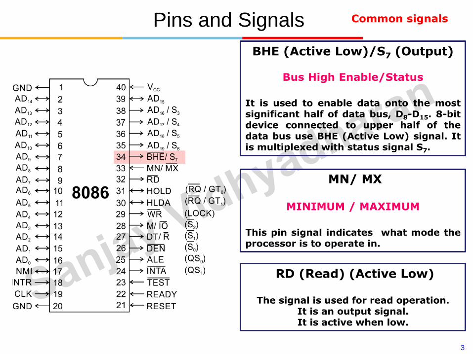
Pins and Signals Common signals
3
Pins and Signals Common signals
BHE (Active Low)/S7 (Output)
Bus High Enable/Status
It is used to enable data onto the mostsignificant half of data bus, D8-D15. 8-bitdevice connected to upper half of thedata bus use BHE (Active Low) signal. Itis multiplexed with status signal S7.
MN/ MX
MINIMUM / MAXIMUM
This pin signal indicates what mode theprocessor is to operate in.
RD (Read) (Active Low)
The signal is used for read operation. It is an output signal. It is active when low.

4
Pins and Signals Common signals
4
TEST
𝐓𝐄𝐒𝐓 input is tested by the ‘WAIT’instruction.
8086 will enter a wait state afterexecution of the WAIT instruction andwill resume execution only when the𝐓𝐄𝐒𝐓 is made low by an active hardware.
This is used to synchronize an externalactivity to the processor internaloperation.
READY
This is the acknowledgement from theslow device or memory that they havecompleted the data transfer.
The signal made available by the devicesis synchronized by the 8284A clockgenerator to provide ready input to the8086.
The signal is active high.

5
Pins and Signals
The 8086 microprocessor can work in twomodes of operations : Minimum mode andMaximum mode.
In the minimum mode of operation themicroprocessor do not associate with anyco-processors and can not be used formultiprocessor systems.
In the maximum mode the 8086 can workin multi-processor or co-processorconfiguration.
Minimum or maximum mode operationsare decided by the pin MN/ MX(Active low).
When this pin is high 8086 operates inminimum mode otherwise it operates inMaximum mode.
Min/ Max Pins

6
Pins and SignalsPins 24 -31
For minimum mode operation, the MN/ 𝐌𝐗 is tied to VCC (logic high)
8086 itself generates all the bus control signals
DT/ഥ𝐑 (Data Transmit/ Receive) Output signal from the processor to control the direction of data flow through the data transceivers
𝐃𝐄𝐍 (Data Enable) Output signal from the processor used as out put enable for the transceivers
ALE (Address Latch Enable) Used to demultiplex the address and data lines using external latches
M/𝐈𝐎 Used to differentiate memory access and I/O access. For memory reference instructions, it is high. For IN and OUT instructions, it is low.
𝐖𝐑 Write control signal; asserted low Whenever processor writes data to memory or I/O port
𝐈𝐍𝐓𝐀 (Interrupt Acknowledge) When the interrupt request is accepted by the processor, the output is low on this line.
Minimum mode signals

7
Pins and Signals Minimum mode signals
HOLD Input signal to the processor form the bus masters as a request to grant the control of the bus.
Usually used by the DMA controller to get the control of the bus.
HLDA (Hold Acknowledge) Acknowledge signal by the processor to the bus master requesting the control of the bus through HOLD.
The acknowledge is asserted high, when the processor accepts HOLD.
Pins 24 -31
For minimum mode operation, the MN/ 𝐌𝐗 is tied to VCC (logic high)
8086 itself generates all the bus control signals

8
Pins and Signals Maximum mode signals
During maximum mode operation, the MN/ 𝐌𝐗 is grounded (logic low)
Pins 24 -31 are reassigned
𝑺𝟎, 𝑺𝟏, 𝑺𝟐 Status signals; used by the 8086 bus controller to generate bus timing and control signals. These are decoded as shown.

9
Pins and Signals Maximum mode signals
During maximum mode operation, the MN/ 𝐌𝐗 is grounded (logic low)
Pins 24 -31 are reassigned
𝑸𝑺𝟎, 𝑸𝑺𝟏 (Queue Status) The processor provides the statusof queue in these lines.
The queue status can be used by external device totrack the internal status of the queue in 8086.
The output on QS0 and QS1 can be interpreted asshown in the table.

10
Pins and Signals Maximum mode signals
During maximum mode operation, the MN/ 𝐌𝐗 is grounded (logic low)
Pins 24 -31 are reassigned
𝐑𝐐/𝐆𝐓𝟎, 𝐑𝐐/𝐆𝐓𝟏
(Bus Request/ Bus Grant) These requests are usedby other local bus masters to force the processorto release the local bus at the end of theprocessor’s current bus cycle.
These pins are bidirectional.
The request on𝐆𝐓𝟎 will have higher priority than𝐆𝐓𝟏
𝐋𝐎𝐂𝐊 An output signal activated by the LOCK prefixinstruction.
Remains active until the completion of theinstruction prefixed by LOCK.
The 8086 output low on the 𝐋𝐎𝐂𝐊 pin while
executing an instruction prefixed by LOCK toprevent other bus masters from gaining control ofthe system bus.

11
Pins and Signals Maximum mode signals
During maximum mode operation, the MN/ 𝐌𝐗 is grounded (logic low)
Pins 24 -31 are reassigned
𝐑𝐐/𝐆𝐓𝟎, 𝐑𝐐/𝐆𝐓𝟏
(Bus Request/ Bus Grant) These requests are usedby other local bus masters to force the processorto release the local bus at the end of theprocessor’s current bus cycle.
These pins are bidirectional.
The request on𝐆𝐓𝟎 will have higher priority than𝐆𝐓𝟏
𝐋𝐎𝐂𝐊 An output signal activated by the LOCK prefixinstruction.
Remains active until the completion of theinstruction prefixed by LOCK.
The 8086 output low on the 𝐋𝐎𝐂𝐊 pin while
executing an instruction prefixed by LOCK toprevent other bus masters from gaining control ofthe system bus.

12
• Thankyou