Curriculum Benefits of Advanced Microprocessor Programming ...
Upload
gary-elliottCategory
view
29download
1description

Microprocessor Programming and Application
Input/Output

Input/Output Problems
Wide variety of peripherals Delivering different amounts of data At different speeds In different formats
All slower than CPU and RAMNeed I/O modules
Input/Output Module
Interface to CPU and MemoryInterface to one or more peripherals
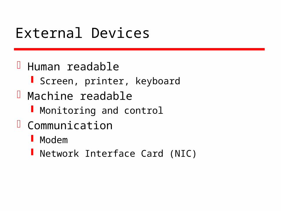
External Devices
Human readable Screen, printer, keyboard
Machine readable Monitoring and control
Communication Modem Network Interface Card (NIC)
I/O Module Function
Control & TimingCPU CommunicationDevice CommunicationData BufferingError Detection

I/O Steps
CPU checks I/O module device statusI/O module returns statusIf ready, CPU requests data transferI/O module gets data from deviceI/O module transfers data to CPUVariations for output, DMA, etc.
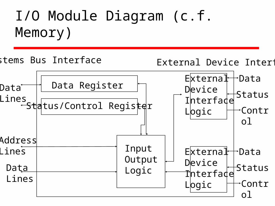
I/O Module Diagram (c.f. Memory)
Data Register
Status/Control Register
ExternalDeviceInterfaceLogic
ExternalDeviceInterfaceLogic
InputOutputLogic
DataLines
AddressLines
DataLines
Data
Status
Control
Data
Status
Control
Systems Bus Interface External Device Interface
I/O Module Decisions
Hide or reveal device properties to CPUSupport multiple or single deviceControl device functions or leave for CPUAlso O/S decisions
e.g. Unix treats everything it can as a file !

Input Output Techniques
ProgrammedInterrupt drivenDirect Memory Access (DMA)
Programmed I/O (a.k.a. polling, busy wait)
CPU has direct control over I/O Sensing status Read/write commands Transferring data
CPU waits for I/O module to complete operation(busy waiting, that is, CPU does nothing really)
Wastes CPU time

Programmed I/O - detail
1. CPU requests I/O operation2. I/O module performs operation3. I/O module sets status bits4. CPU checks status bits periodically5. I/O module does not inform CPU directly6. I/O module does not interrupt CPU7. CPU may wait or come back later
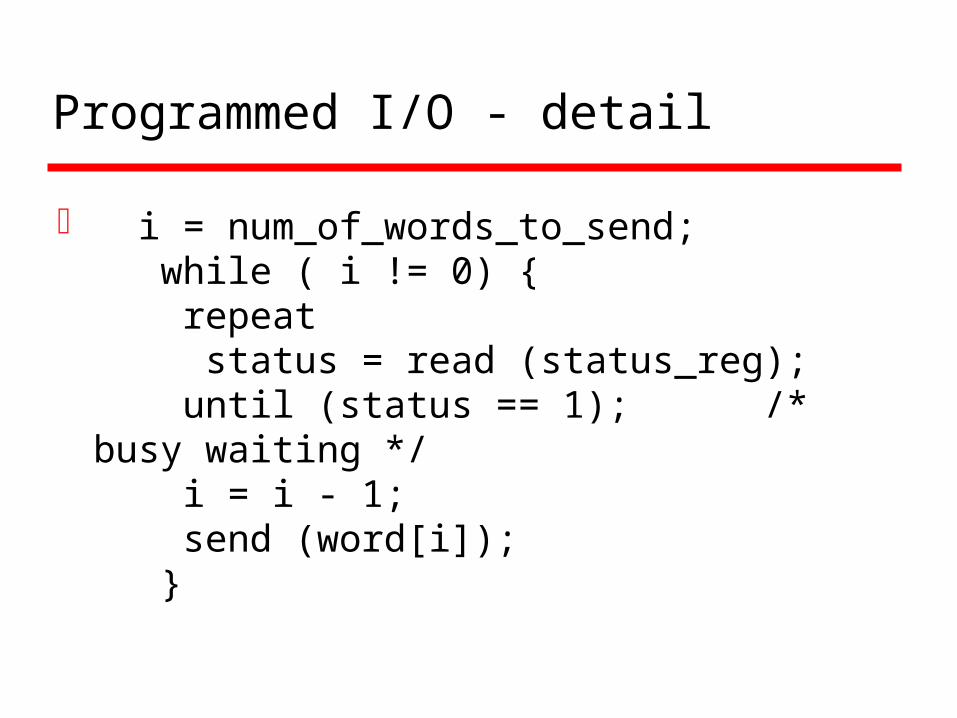
Programmed I/O - detail
i = num_of_words_to_send; while ( i != 0) { repeat status = read (status_reg); until (status == 1); /* busy waiting */ i = i - 1; send (word[i]); }
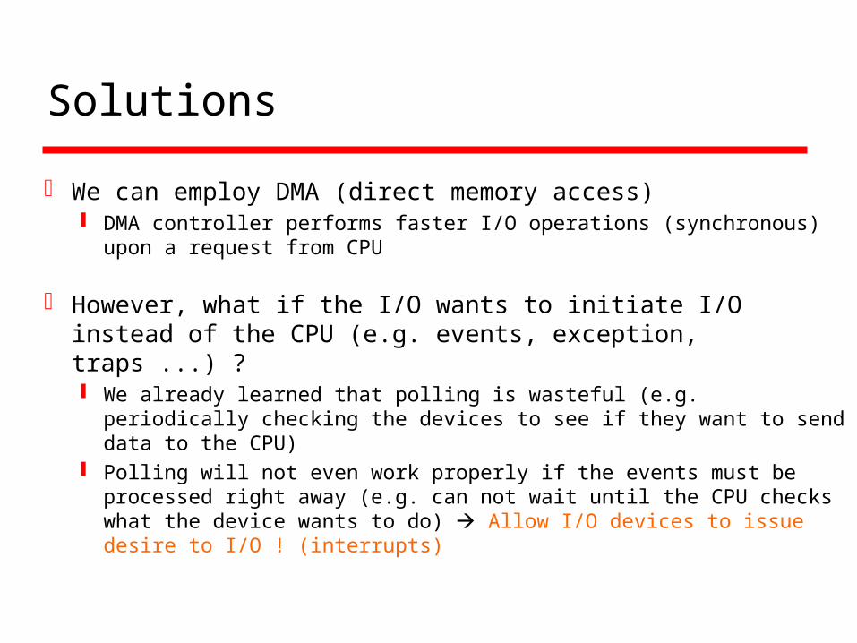
Solutions
We can employ DMA (direct memory access) DMA controller performs faster I/O operations (synchronous) upon a
request from CPU
However, what if the I/O wants to initiate I/O instead of the CPU (e.g. events, exception, traps ...) ? We already learned that polling is wasteful (e.g. periodically checking
the devices to see if they want to send data to the CPU) Polling will not even work properly if the events must be processed
right away (e.g. can not wait until the CPU checks what the device wants to do) Allow I/O devices to issue desire to I/O ! (interrupts)
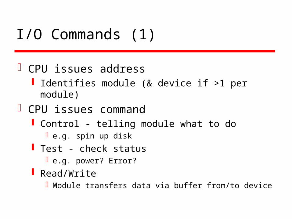
I/O Commands (1)
CPU issues address Identifies module (& device if >1 per module)
CPU issues command Control - telling module what to do
e.g. spin up disk
Test - check statuse.g. power? Error?
Read/WriteModule transfers data via buffer from/to device
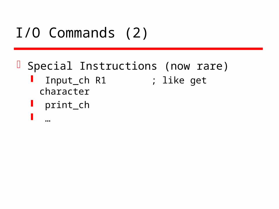
I/O Commands (2)
Special Instructions (now rare) Input_ch R1 ; like get character print_ch …
Addressing I/O Devices
Under programmed I/O data transfer is very like memory access (CPU viewpoint)
Each device given unique identifier CPU commands contain identifier (address)
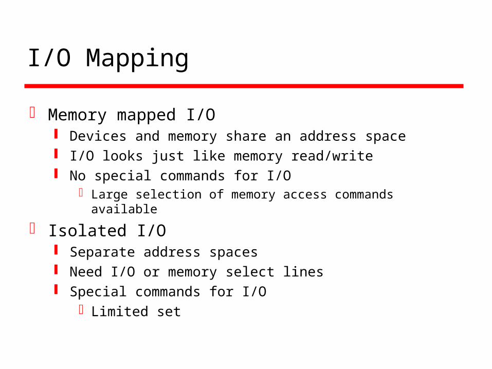
I/O Mapping
Memory mapped I/O Devices and memory share an address space I/O looks just like memory read/write No special commands for I/O
Large selection of memory access commands available
Isolated I/O Separate address spaces Need I/O or memory select lines Special commands for I/O
Limited set

Interrupt Driven I/O
Overcomes CPU waiting No repeated CPU checking of device I/O module interrupts when ready
A way of I/O devices to alert the CPU by activating one of the control lines (Interrupt Request) of the CPU
Then, CPU "services" the interrupt and returns to its normal processing state. CPU does not poll on anything because the devices can raise interrupt any time they want (Asynchronous) similar to procedure call ! (think of the exam problem)

Interrupt Driven I/OBasic Operation
1. CPU issues read command2. I/O module gets data from peripheral whilst CPU
does other work3. I/O module interrupts CPU4. CPU requests data5. I/O module transfers data
a bit more efficient also (aside from the advantage of allowing I/O device to request I/O operations)
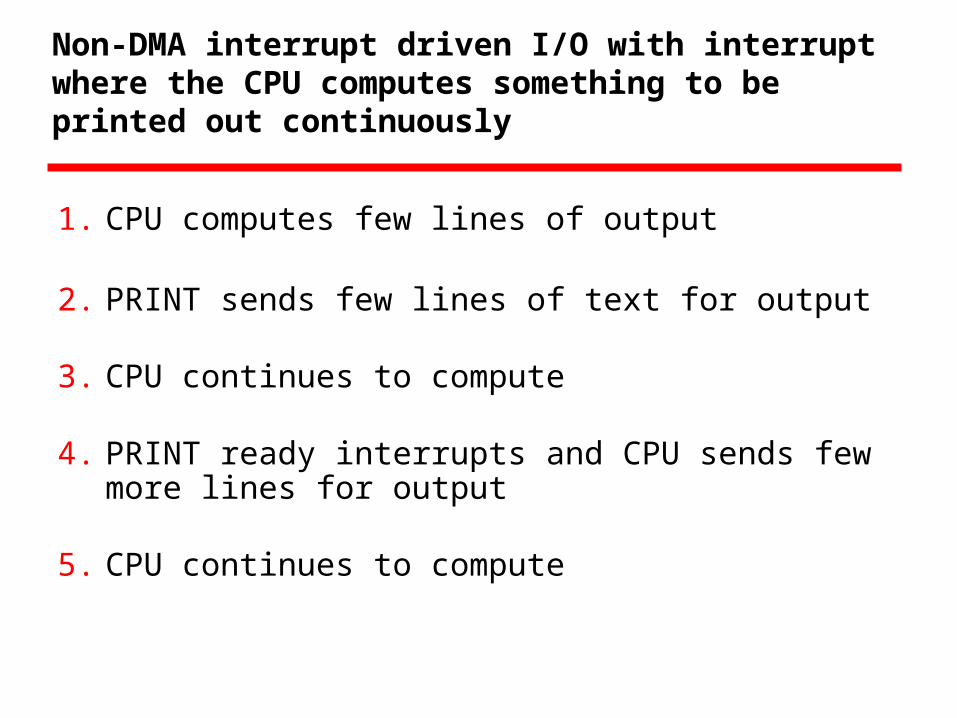
Non-DMA interrupt driven I/O with interrupt where the CPU computes something to be printed out continuously
1. CPU computes few lines of output
2. PRINT sends few lines of text for output
3. CPU continues to compute
4. PRINT ready interrupts and CPU sends few more lines for output
5. CPU continues to compute
CPU Viewpoint
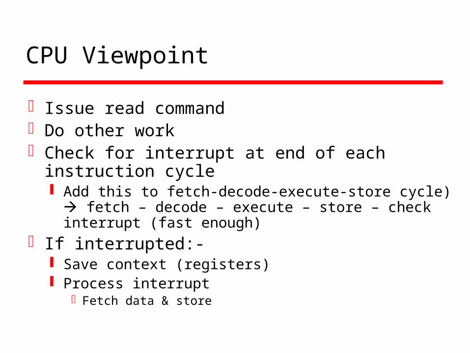
Issue read commandDo other workCheck for interrupt at end of each instruction
cycle Add this to fetch-decode-execute-store cycle)
fetch – decode – execute – store – check interrupt (fast enough)
If interrupted:- Save context (registers) Process interrupt
Fetch data & store
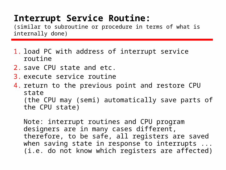
Interrupt Service Routine: (similar to subroutine or procedure in terms of what is internally done)
1. load PC with address of interrupt service routine 2. save CPU state and etc. 3. execute service routine 4. return to the previous point and restore CPU state
(the CPU may (semi) automatically save parts of the CPU state) Note: interrupt routines and CPU program designers are in many cases different, therefore, to be safe, all registers are saved when saving state in response to interrupts ... (i.e. do not know which registers are affected)

Issues
How do you identify the module issuing the interrupt?
How do you deal with multiple/simultaneous interrupts? i.e. an interrupt handler being interrupted

Arrival of interrupt
It can be any time, but there are cases that the CPU does not want to or can not handle the interrupt (when ?)
We need the capability to "enable" or "disable" incoming interrupts ... Interrupt Masking: placing a user programmable interrupt mask register on
interrupt request lines. The interrupt request line is ANDed with contents of mask register ...
More generally, we need the capability to selectively "enable" or "disable" certain (not just all) interrupts ... e.g. PRINT should interrupt CPU when CPU is ready only, so the
CPU will disable the interrupt until it is ready to output something ... Incoming interrupts may be served based on priority or
completely be ignored ...

Identifying who interrupts (1)
Different hardware line for each module Limits number of devices
Software poll CPU asks each module in turn
(interrupt controller in the middle) Slow

Identifying who interrupts (2)
Daisy Chain or Hardware poll Interrupt Acknowledge sent down a chain Module responsible places vector on bus CPU uses vector to identify handler routine
Bus Master Module must claim the bus before it can raise
interrupt e.g. PCI & SCSI
Vectored interrupt
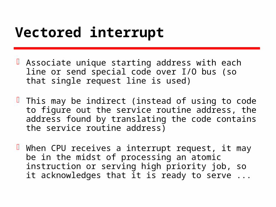
Associate unique starting address with each line or send special code over I/O bus (so that single request line is used)
This may be indirect (instead of using to code to figure out the service routine address, the address found by translating the code contains the service routine address)
When CPU receives a interrupt request, it may be in the midst of processing an atomic instruction or serving high priority job, so it acknowledges that it is ready to serve ...
Figuring out Interrupt Service Address
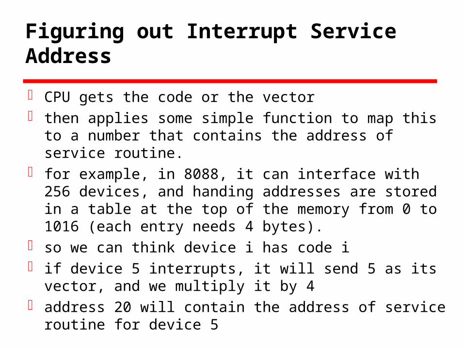
CPU gets the code or the vector then applies some simple function to map this to a
number that contains the address of service routine. for example, in 8088, it can interface with 256
devices, and handing addresses are stored in a table at the top of the memory from 0 to 1016 (each entry needs 4 bytes).
so we can think device i has code i if device 5 interrupts, it will send 5 as its vector, and
we multiply it by 4 address 20 will contain the address of service
routine for device 5
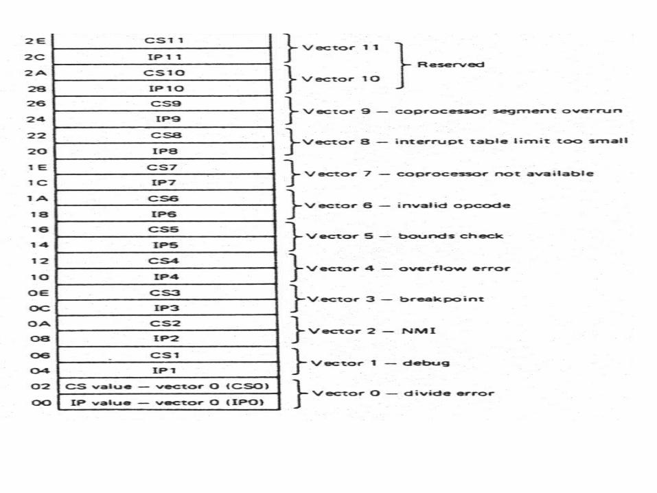
Figuring out Interrupt Service Address
For each vector, the starting address is stored at the top of the memory (memory location 0 to 255*4)
For each vector, 4 bytes are needed, 2 for the segment address and 2 for the offset (IP)
Multiple Interrupts
Each interrupt line has a priorityHigher priority lines can interrupt lower
priority lines
Interrupt Priorities (1)
For instance, a timer must have very high priority so that the time is kept right ...
If CPU polls on devices upon interrupt request, device that is polled first gets served first
In a daisy chain where interrupt request acknowledge line is chained among devices (the acknowledge passes through the devices until reaching the first device requesting the interrupt). The first device electrically close to the CPU gets served first ... (Closer the device is chained, the higher its priority priority)
Interrupt Priorities (2)
A priority handling circuitry can be made to accept from multiple request lines (one request per device for example) and the priority handling circuit determines who to serve by sending the acknowledge signal to the device with highest priority. This method is more flexible but requires more hardware
And, of course, the daisy chain and priority handling circuitry can be mixed ... (several devices daisy chained for one priority group) ...

Interrupt during Interrupt (1)
Ignore any interrupt during interrupt service, or
Allow higher priority to be served Jump to higher priority interrupt service routine as
usual Save information about any incoming lower priority
interrupt requests in a stack as pending so that these can be served after the high priority ones are served
Interrupt during Interrupt (2)
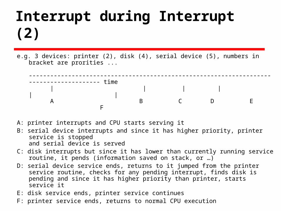
e.g. 3 devices: printer (2), disk (4), serial device (5), numbers in bracket are prorities ...
---------------------------------------------------------------------------------------- time
| | | | | | A B C D E F
A: printer interrupts and CPU starts serving itB: serial device interrupts and since it has higher priority, printer service
is stoppedand serial device is served
C: disk interrupts but since it has lower than currently running service routine, it pends (information saved on stack, or …)
D: serial device service ends, returns to it jumped from the printer service routine, checks for any pending interrupt, finds disk is pending and since it has higher priority than printer, starts service it
E: disk service ends, printer service continuesF: printer service ends, returns to normal CPU execution
Exception
Interrupts are generated internally by CPU) When ?
Some undesirable CPU state (divide by zero, illegal memory access, etc) like external events, they must be servied by interrupt routines
Therefore, they too have vector numbers associated with types of exceptions which would be higher priority than user external interrupts, and their address table is located with the address table for the user external interrupts
Summary
CPU initiated (Programmed) I/O Talk to device or I/O Module (for loops)
Device initiated I/O Device send interrupt signal CPU checks interrupt arrival very fast (F-D-E-(S)-CI)
If interrupted, send ack to requesting device Note that CPU can ignore interrupt request by setting
interrupt mast register The requesting device place vector (id) on bus CPU gets the id and apply some function to get address of
table entry where subroutine address is stored That vector-to-address table is called interrupt vector table
and sits somewhere in memory (fixed) Save CPU state and jump If higher priority interrupt comes in nested jump

Interrupt interface (Daisy Chain)
CPU
D1 D3D2
Data bus
~INTR
ACK
Vector

Interrupt interface (Priority CKT)
CPU
Priority Handling CKT
D1 D3D2
Data bus
~INTR
ACK
Vector
ACK
INTR
Mask Reg.
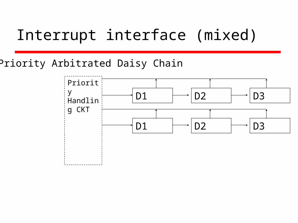
Interrupt interface (mixed)
Priority Handling CKT D1 D3D2
D1 D3D2
Priority Arbitrated Daisy Chain

Example - PC Bus
80x86 has one interrupt line8086 based systems use one 8259A
interrupt controller8259A has 8 interrupt lines
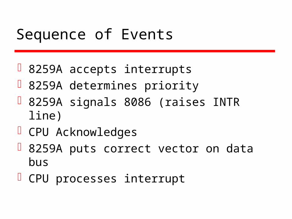
Sequence of Events
8259A accepts interrupts8259A determines priority8259A signals 8086 (raises INTR line)CPU Acknowledges8259A puts correct vector on data busCPU processes interrupt

PC Interrupt Layout
8086
INTR
8259A
IRQ0IRQ1IRQ2IRQ3IRQ4IRQ5IRQ6IRQ7

ISA Bus Interrupt System
ISA bus chains two 8259As togetherLink is via interrupt 2Gives 15 lines
16 lines less one for link
IRQ 9 is used to re-route anything trying to use IRQ 2 Backwards compatibility
Incorporated in chip set
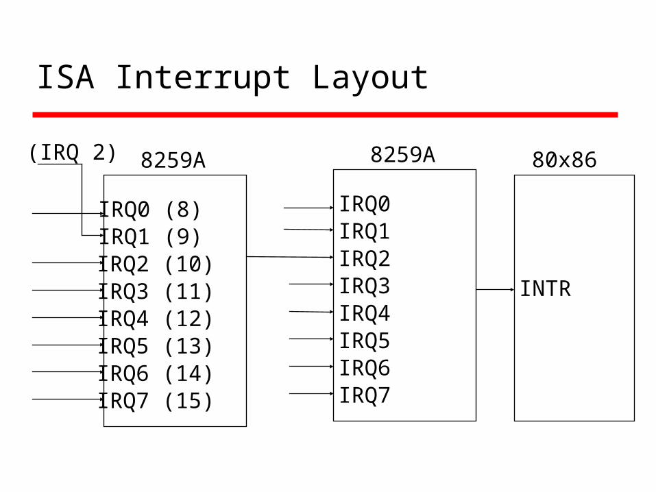
ISA Interrupt Layout
80x86
INTR
8259A
IRQ0IRQ1IRQ2IRQ3IRQ4IRQ5IRQ6IRQ7
8259A
IRQ0 (8)IRQ1 (9)IRQ2 (10)IRQ3 (11)IRQ4 (12)IRQ5 (13)IRQ6 (14)IRQ7 (15)
(IRQ 2)
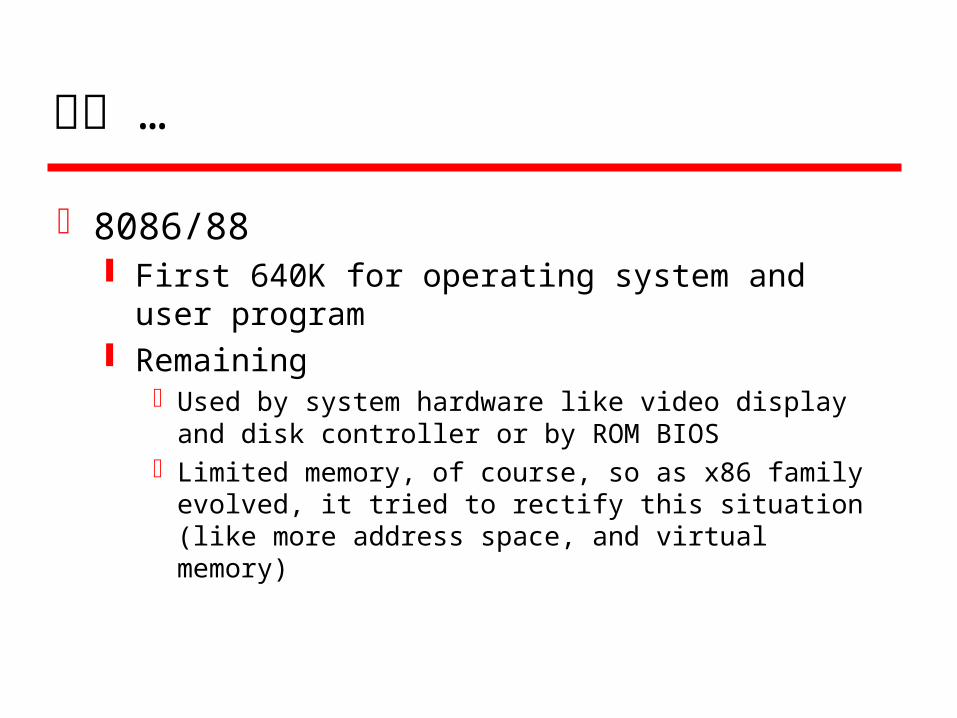
잠깐 …
8086/88 First 640K for operating system and user
program Remaining
Used by system hardware like video display and disk controller or by ROM BIOS
Limited memory, of course, so as x86 family evolved, it tried to rectify this situation (like more address space, and virtual memory)
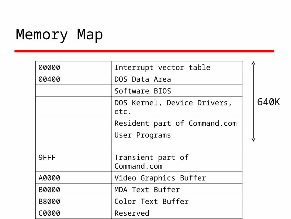
Memory Map
00000 Interrupt vector table
00400 DOS Data Area
Software BIOS
DOS Kernel, Device Drivers, etc.
Resident part of Command.com
User Programs
9FFF Transient part of Command.com
A0000 Video Graphics Buffer
B0000 MDA Text Buffer
B8000 Color Text Buffer
C0000 Reserved
F0000 ROM BIOS
640K
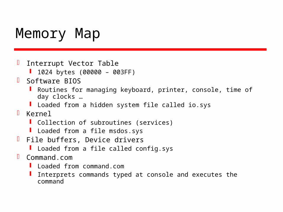
Memory Map
Interrupt Vector Table 1024 bytes (00000 – 003FF)
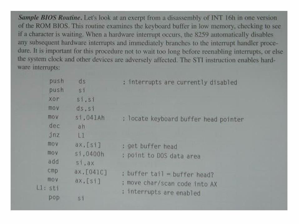
Software BIOS Routines for managing keyboard, printer, console, time of day
clocks … Loaded from a hidden system file called io.sys
Kernel Collection of subroutines (services) Loaded from a file msdos.sys
File buffers, Device drivers Loaded from a file called config.sys
Command.com Loaded from command.com Interprets commands typed at console and executes the command

Memory Map
04000-04007 Port address, COM1 – COM4
04008-0400F Port address LPT1 – LPT 4
04017-04018 Keyboard status flag
0401A-0403D Keyboard buffer pointers
0406C-04070 Timer data area
COM1 04000 Port address: 03F8
COM2 04002 Port address: 02F8
04017-04018 04004 -
0401A-0403D 04006 -

Memory map and system startup
The “mysterious force” Computer power is on Booted Boot process
CPU jumps to an initialization program in ROM BIOS BIOS (Basic Input Output System: Collection of system
programs) In Read Only Memory (lives permanently): a.k.a. Firmware First checks if all hardware is present and in working condition CPU is designed to execute this program from ROM when power
is turned on (F-D-E-S) After some tests: Track zero of “designated disk” (or floppy) is
accessed bootloader program There is another boot program there (“loaded by bootloader of
BIOS)• This loads the io.sys, msdos.sys, …, and command.com• Autoexec.bat and config.sys can be used to initialize certain settings
in the midst of this

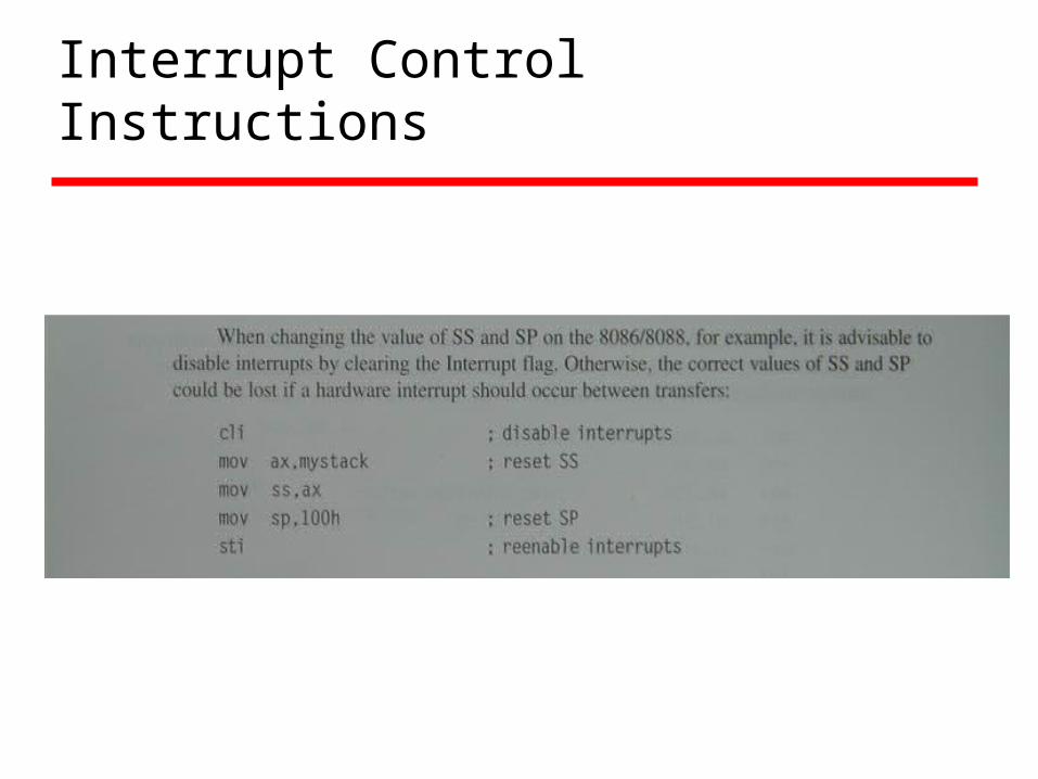
Interrupt Control Instructions


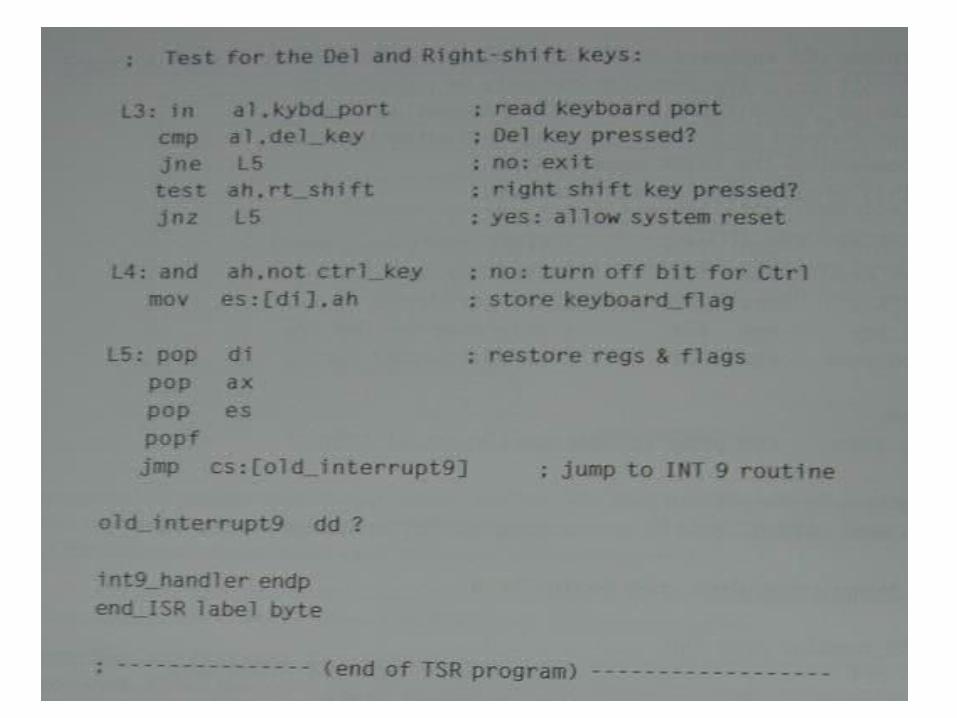


Exceptions
Abnormal thingsA.k.a. Traps, Faults (some subtle difference
but …)Software interruptsSame mechanism as interrupts except
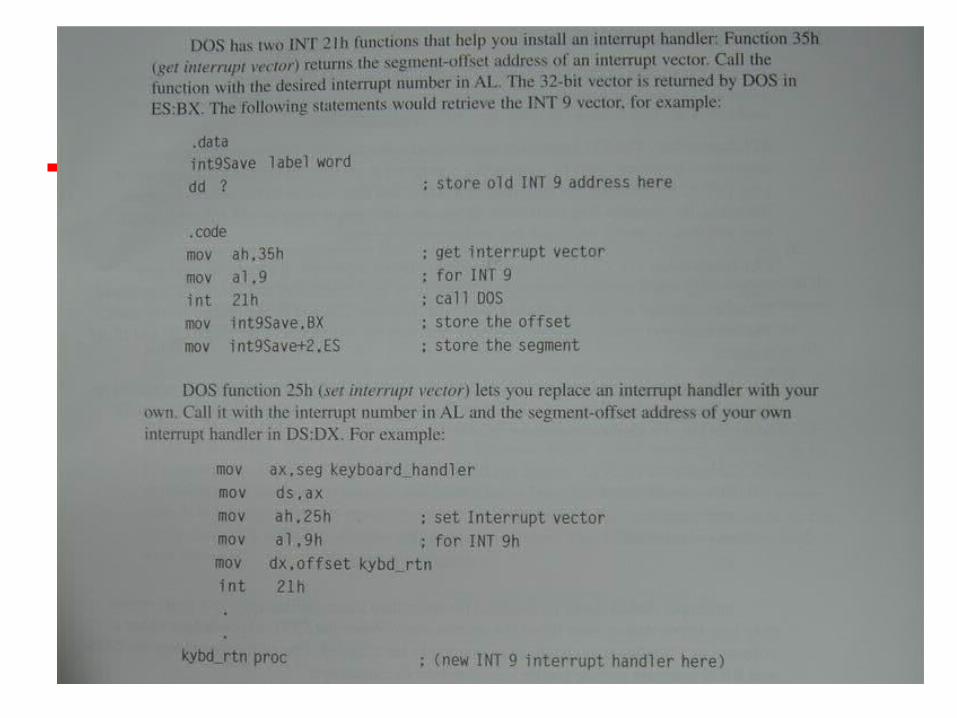
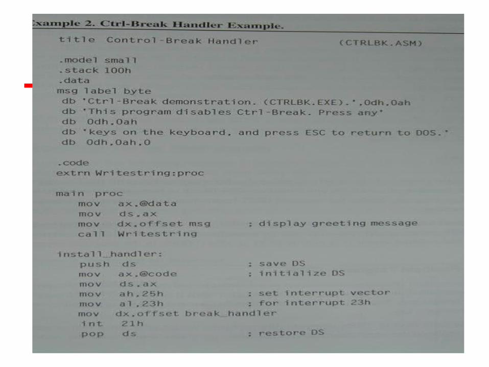
interrupts are generated internallyUsed also for certain system callsExample: Int 21
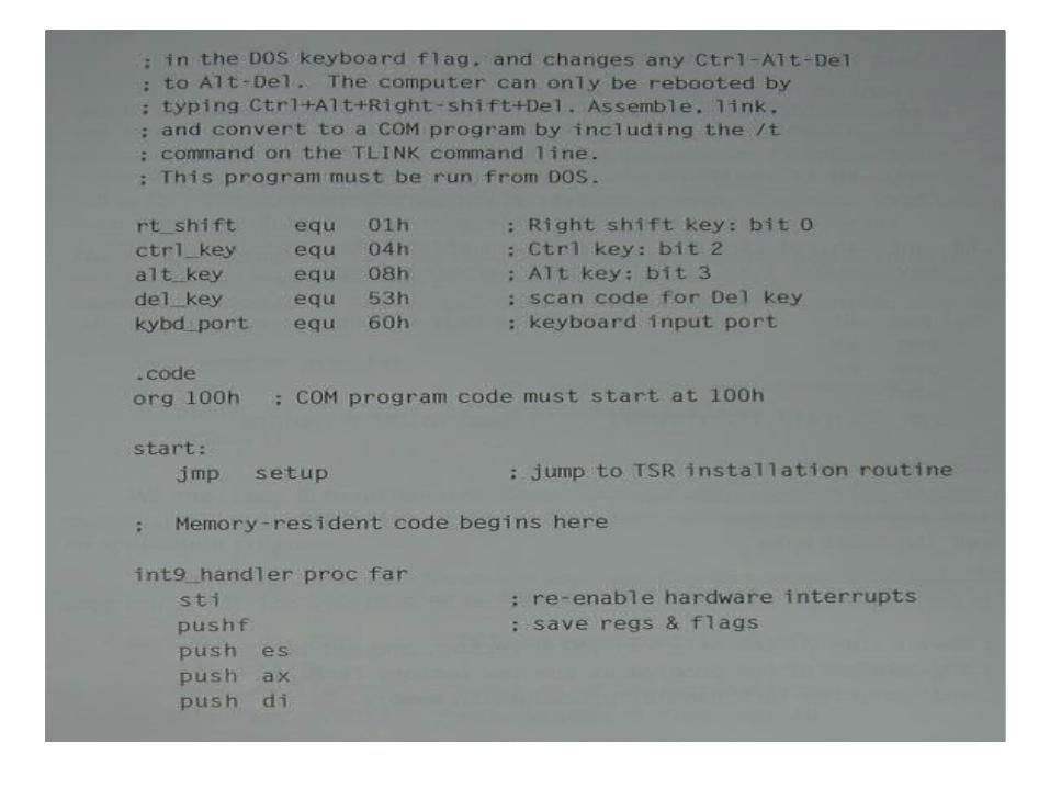
Int 21 has its own keyboard interface But Keyboard can be handled by Int 16H as well
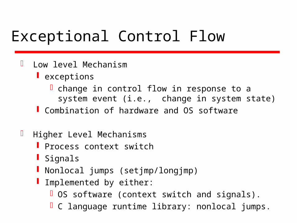
Exceptional Control Flow
Low level Mechanism exceptions
change in control flow in response to a system event (i.e., change in system state)
Combination of hardware and OS software
Higher Level Mechanisms Process context switch Signals Nonlocal jumps (setjmp/longjmp) Implemented by either:
OS software (context switch and signals).C language runtime library: nonlocal jumps.
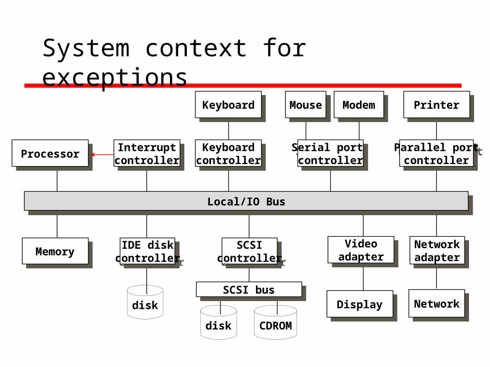
System context for exceptions
Local/IO BusLocal/IO Bus
MemoryMemory Networkadapter
Networkadapter
IDE diskcontroller
IDE diskcontroller
Videoadapter
Videoadapter
DisplayDisplay NetworkNetwork
ProcessorProcessor Interruptcontroller
Interruptcontroller
SCSIcontroller
SCSIcontroller
SCSI busSCSI bus
Serial port controller
Serial port controller
Parallel portcontroller
Parallel portcontroller
Keyboardcontroller
Keyboardcontroller
KeyboardKeyboard MouseMouse PrinterPrinterModemModem
disk
disk CDROM

Exceptions
An exception is a transfer of control to the OS in response to some event (i.e., change in processor state)
User Process OS
exceptionexception processingby exception handler
exception return (optional)
event currentnext

Asynchronous Exceptions (Interrupts)
Caused by events external to the processor Indicated by setting the processor’s interrupt pin handler returns to “next” instruction.
Examples: I/O interrupts
hitting ctl-c at the keyboardarrival of a packet from a networkarrival of a data sector from a disk
Hard reset interrupthitting the reset button
Soft reset interrupthitting ctl-alt-delete on a PC
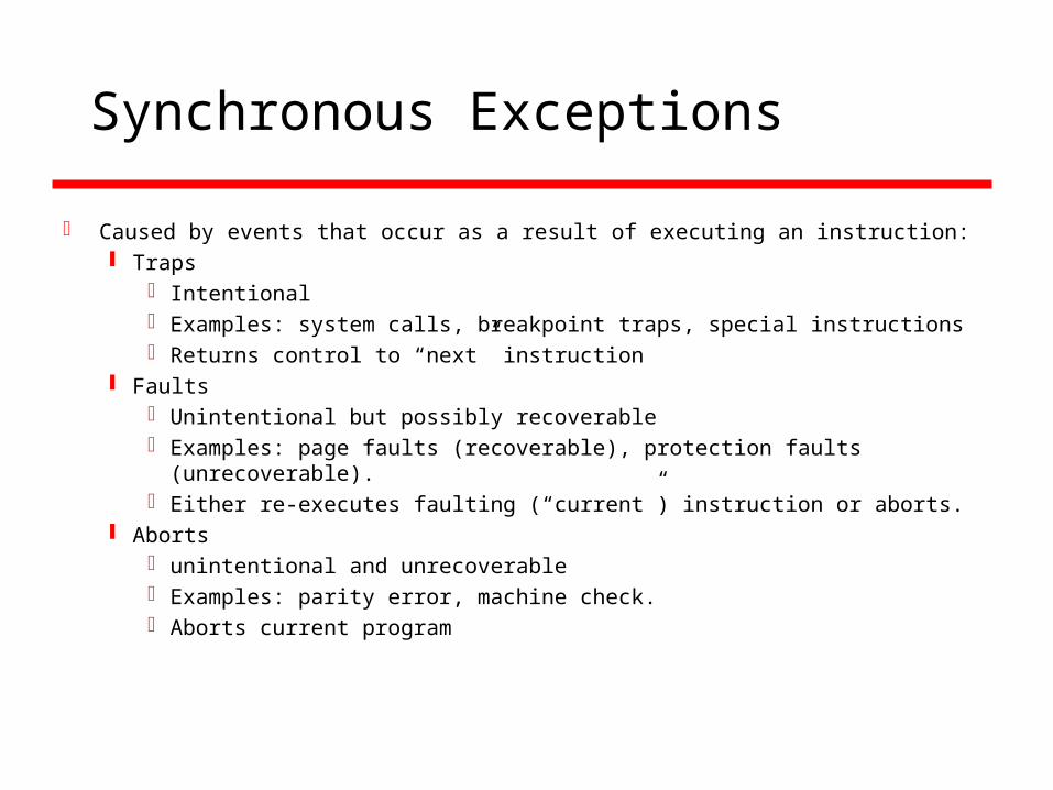
Synchronous Exceptions
Caused by events that occur as a result of executing an instruction: Traps
Intentional Examples: system calls, breakpoint traps, special instructions Returns control to “next” instruction
Faults Unintentional but possibly recoverable Examples: page faults (recoverable), protection faults
(unrecoverable). Either re-executes faulting (“current”) instruction or aborts.
Aborts unintentional and unrecoverable Examples: parity error, machine check. Aborts current program

Trap Example (system call)Trap Example (system call)
Opening a File User calls open(filename, options)
Function open executes system call instruction int
OS must find or create file, get it ready for reading or writing
Returns integer file descriptor
0804d070 <__libc_open>: . . . 804d082: cd 80 int $0x80 804d084: 5b pop %ebx . . .

Trap ExampleTrap Example
User Process OS
exception
Open file
return
intpop
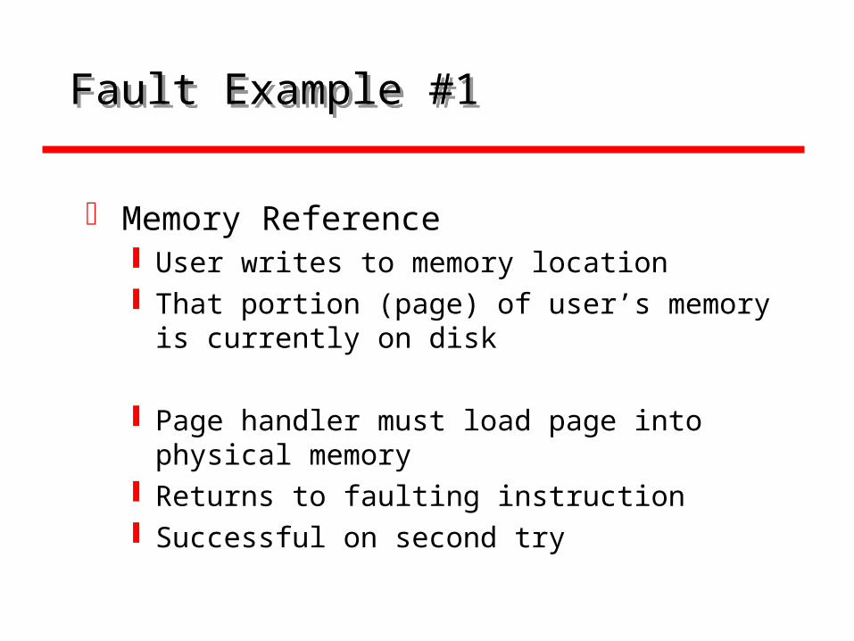
Fault Example #1Fault Example #1
Memory Reference User writes to memory location That portion (page) of user’s memory is
currently on disk
Page handler must load page into physical memory
Returns to faulting instruction Successful on second try
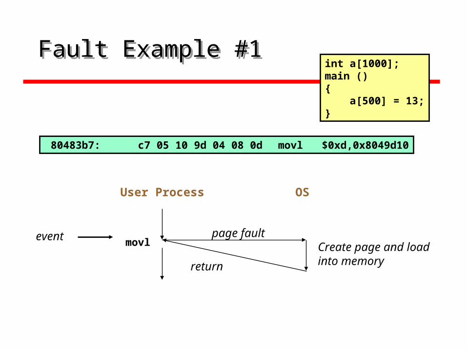
Fault Example #1Fault Example #1
User Process OS
page faultCreate page and load into memoryreturn
event movl
int a[1000];main (){ a[500] = 13;}
80483b7: c7 05 10 9d 04 08 0d movl $0xd,0x8049d10

Fault Example #2Fault Example #2
Memory Reference User writes to memory location Address is not valid
Page handler detects invalid address Sends SIGSEG signal to user process User process exits with “segmentation
fault”
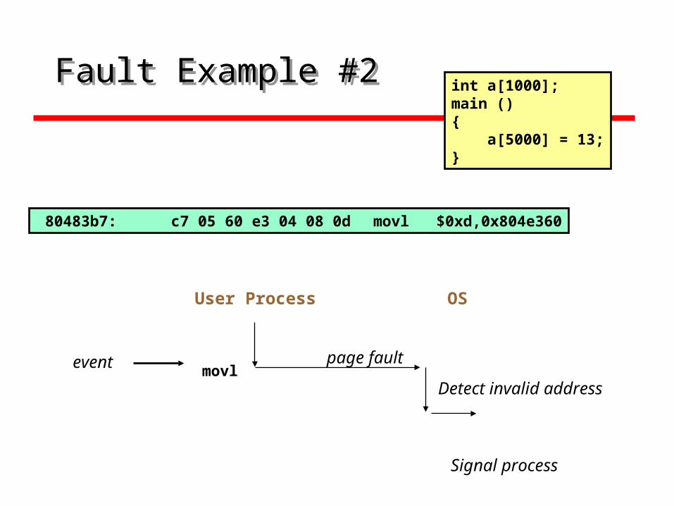
Fault Example #2Fault Example #2
User Process OS
page fault
Detect invalid address
event movl
int a[1000];main (){ a[5000] = 13;}
80483b7: c7 05 60 e3 04 08 0d movl $0xd,0x804e360
Signal process
Direct Memory Access
Interrupt driven and programmed I/O require active CPU intervention Transfer rate is limited CPU is tied up
DMA is the answer

DMA Function
Additional Module (hardware) on busDMA controller takes over from CPU for I/O

DMA Operation
CPU tells DMA controller:- Read/Write Device address Starting address of memory block for data Amount of data to be transferred
CPU carries on with other workDMA controller deals with transferDMA controller sends interrupt when
finished
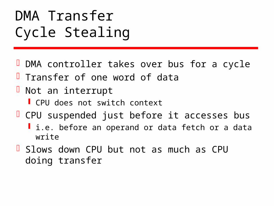
DMA TransferCycle Stealing
DMA controller takes over bus for a cycleTransfer of one word of dataNot an interrupt
CPU does not switch context
CPU suspended just before it accesses bus i.e. before an operand or data fetch or a data
write
Slows down CPU but not as much as CPU doing transfer
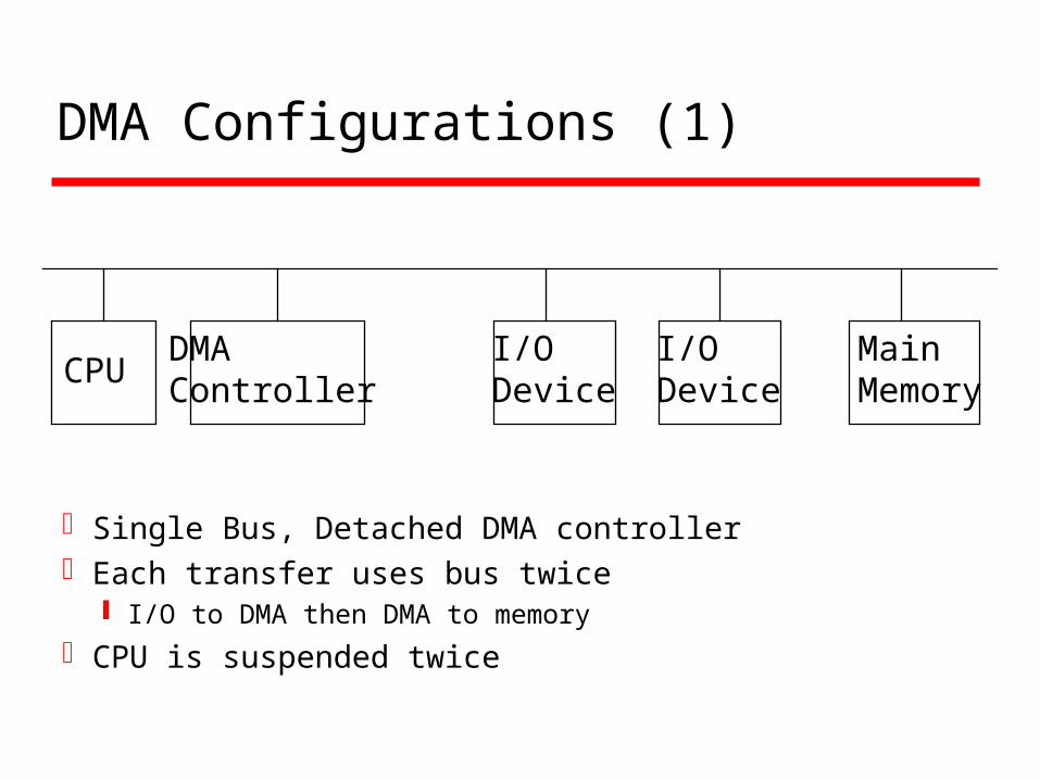
DMA Configurations (1)
Single Bus, Detached DMA controllerEach transfer uses bus twice
I/O to DMA then DMA to memory
CPU is suspended twice
CPUDMAController
I/ODevice
I/ODevice
Main Memory

DMA Configurations (2)
Single Bus, Integrated DMA controllerController may support >1 deviceEach transfer uses bus once
DMA to memory
CPU is suspended once
CPUDMAController
I/ODevice
I/ODevice
Main Memory
DMAController
I/ODevice
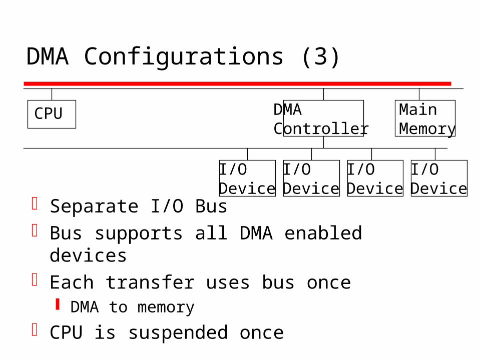
DMA Configurations (3)
Separate I/O BusBus supports all DMA enabled devicesEach transfer uses bus once
DMA to memory
CPU is suspended once
CPU DMAController
I/ODevice
I/ODevice
Main Memory
I/ODevice
I/ODevice
I/O Channels
I/O devices getting more sophisticatede.g. 3D graphics cardsCPU instructs I/O controller to do transferI/O controller does entire transferImproves speed
Takes load off CPU Dedicated processor is faster