Microphone Techniques - Recordingfaculty.mccneb.edu/ccarlson/VACA1010/VACA1010_CD... · Microphone...
40
A Shure Educational Publication RECORDING MICROPHONE TECHNIQUES
-
Upload
truongkhue -
Category
Documents
-
view
240 -
download
3
Transcript of Microphone Techniques - Recordingfaculty.mccneb.edu/ccarlson/VACA1010/VACA1010_CD... · Microphone...
A Shure Educational Publ icat ion
RECORDING
MICROPHONE TECHNIQUES
3
RECORDINGMicrophone Techniquesfor
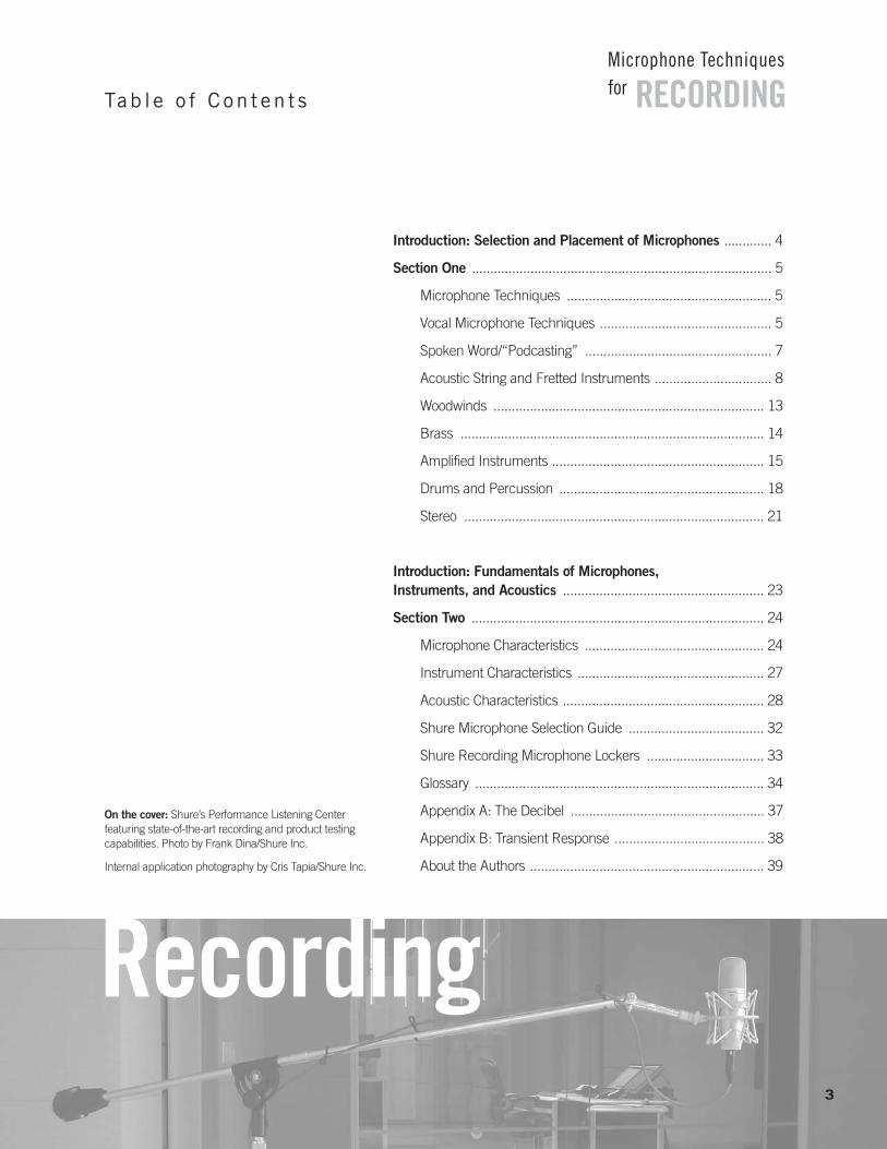
Introduction: Selection and Placement of Microphones ............. 4
Section One .................................................................................. 5
Microphone Techniques ........................................................ 5
Vocal Microphone Techniques ............................................... 5
Spoken Word/“Podcasting” ................................................... 7
Acoustic String and Fretted Instruments ................................ 8
Woodwinds .......................................................................... 13
Brass ................................................................................... 14
Amplified Instruments .......................................................... 15
Drums and Percussion ........................................................ 18
Stereo .................................................................................. 21
Introduction: Fundamentals of Microphones,Instruments, and Acoustics ....................................................... 23
Section Two ................................................................................ 24
Microphone Characteristics ................................................. 24
Instrument Characteristics ................................................... 27
Acoustic Characteristics ....................................................... 28
Shure Microphone Selection Guide ..................................... 32
Shure Recording Microphone Lockers ................................ 33
Glossary ............................................................................... 34
Appendix A: The Decibel ..................................................... 37
Appendix B: Transient Response ......................................... 38
About the Authors ................................................................ 39
Recording
Tab l e o f C on t en t s
On the cover: Shure’s Performance Listening Center featuring state-of-the-art recording and product testingcapabilities. Photo by Frank Dina/Shure Inc.
Internal application photography by Cris Tapia/Shure Inc.
Introduction
The selection and placement of microphones can have
a major influence on the sound of an acoustic recording.
It is a common view in the recording industry that the music
played by a skilled musician with a quality instrument
properly miked can be sent directly to the recorder with little
or no modification. This simple approach can often sound
better than an instrument that has been reshaped by a
multitude of signal processing gear.
In this guide, Shure Application Engineers describe
particular microphone techniques and placement:
techniques to pick up a natural tonal balance, techniques
to help reject unwanted sounds, and even techniques to
create special effects.
Following this, some fundamentals of microphones,
instruments, and acoustics are presented.
Section One
RECORDINGMicrophone Techniquesfor
4
SECTION ONE
Microphone TechniquesHere is a very basic, general procedure to keep in mindwhen miking something that makes sound:
1) Use a microphone with a frequency response that issuited to the frequency range of the sound, if possible, or filter out frequencies above and/or belowthe highest and lowest frequencies of the sound.
2) Place the microphone at various distances and positions until you find a spot where you hear from thestudio monitors the desired tonal balance and the desired amount of room acoustics. If you don’t like it,try another position, try another microphone, try isolating the instrument further, or change the soundof the instrument itself. For example, replacing wornout strings will change the sound of a guitar.
3) Often you will encounter poor room acoustics, orpickup of unwanted sounds. In these cases, placethe microphone very close to the loudest part of the instrument or isolate the instrument. Again, experiment with microphone choice, placement andisolation, to minimize the undesirable and accentuatethe desirable direct and ambient acoustics.
Microphone technique is largely a matter of personal taste.Whatever method sounds right for the particular sound, instrument, musician, and song is right. There is no one idealway to place a microphone. There is also no one ideal micro-phone to use on any particular instrument. Choose and placethe microphone to get the sound you want. We recommendexperimenting with all sorts of microphones and positions untilyou create your desired sound. However, the desired soundcan often be achieved more quickly by understanding basicmicrophone characteristics, sound-radiation properties of musical instruments, and basic room acoustics.
Vocal Microphone TechniquesIndividual Vocals Microphones with various polar patterns can be used invocal recording techniques. Consider recording a choralgroup or vocal ensemble. Having the vocalists circlearound an omnidirectional mic allows well trained singersto perform as they would live: creating a blend of voices bychanging their individual singing levels and timbres. Two
cardioid mics, positioned back to back could be used forthis same application.
An omnidirectional mic may be used for a single vocalist aswell. If the singer is in a room with ambience and reverbthat add to the desired effect, the omnidirectional mic willcapture the room sound as well as the singer’s direct voice.By changing the distance of the vocalist to the microphone,you can adjust the balance of the direct voice to the ambience. The closer the vocalist is to the mic, the moredirect sound is picked up relative to the ambience.
The standard vocal recording environment usually capturesthe voice only. This typically requires isolation and the use ofa unidirectional mic. Isolation can be achieved with baffles surrounding the vocalist like a “shell” or some other methodof reducing reflected sound from the room. Remember evena music stand can cause reflections back to the mic.
The axis of the microphone should usually be pointed some-where between the nose and mouth to pick up the completesound of the voice. Though the mic is usually directly in frontof the singer’s mouth, a slightly off-axis placement may helpto avoid explosive sounds from breath blasts or certain consonant sounds such as “p”, “b”, “d”, or “t”. Placing themic even further off-axis, or the use of an accessory popfilter, may be necessary to fully eliminate this problem.
While many vocals are recorded professionally in an isolation booth with a cardioid condenser microphone,other methods of vocal recording are practiced. For instance, a rock band’s singers may be uncomfortable inthe isolated environment described earlier. They may beused to singing in a loud environment with a monitor loudspeaker as the reference. This is a typical performancesituation and forces them to sing louder and push theirvoices in order to hear themselves. This is a difficult situation to recreate with headphones.
A technique that has been used successfully in this situation is to bring the singers into the control room to perform. This would be especially convenient for projectstudios that exist in only one room. Once in that environment, a supercardioid dynamic microphone couldbe used in conjunction with the studio monitors. The singerfaces the monitors to hear a mix of music and voice together. The supercardioid mic rejects a large amount ofthe sound projected from the speakers if the rear axis of themicrophone is aimed between the speakers and the speakersare aimed at the null angle of the mic (about 65 degrees oneither side of its rear axis). Just as in live sound, you are using
5
RECORDINGMicrophone Techniquesfor
the polar pattern of the mic to improve gain-before-feedbackand create an environment that is familiar and encouragingto the vocalists. Now the vocalist can scream into the latehours of the night until that vocal track is right.
Ensemble Vocals A condenser is the type of microphone most often usedfor choir applications. They are generally more capable offlat, wide-range frequency response. The most appropriatedirectional type is a unidirectional, usually a cardioid. A supercardioid or a hypercardioid microphone may beused for a slightly greater reach or for more ambient sound rejection. Balanced low-impedance output is used exclusively, and the sensitivity of a condenser microphoneis desirable because of the greater distance between thesound source and the microphone.
Application of choir microphones falls into the categoryknown as “area” coverage. Rather than one microphoneper sound source, the object is to pick up multiple soundsources (or a “large” sound source) with one (or more) microphone(s). Obviously, this introduces the possibility ofinterference effects unless certain basic principles (such asthe “3-to-1 rule”) are followed, as discussed below.
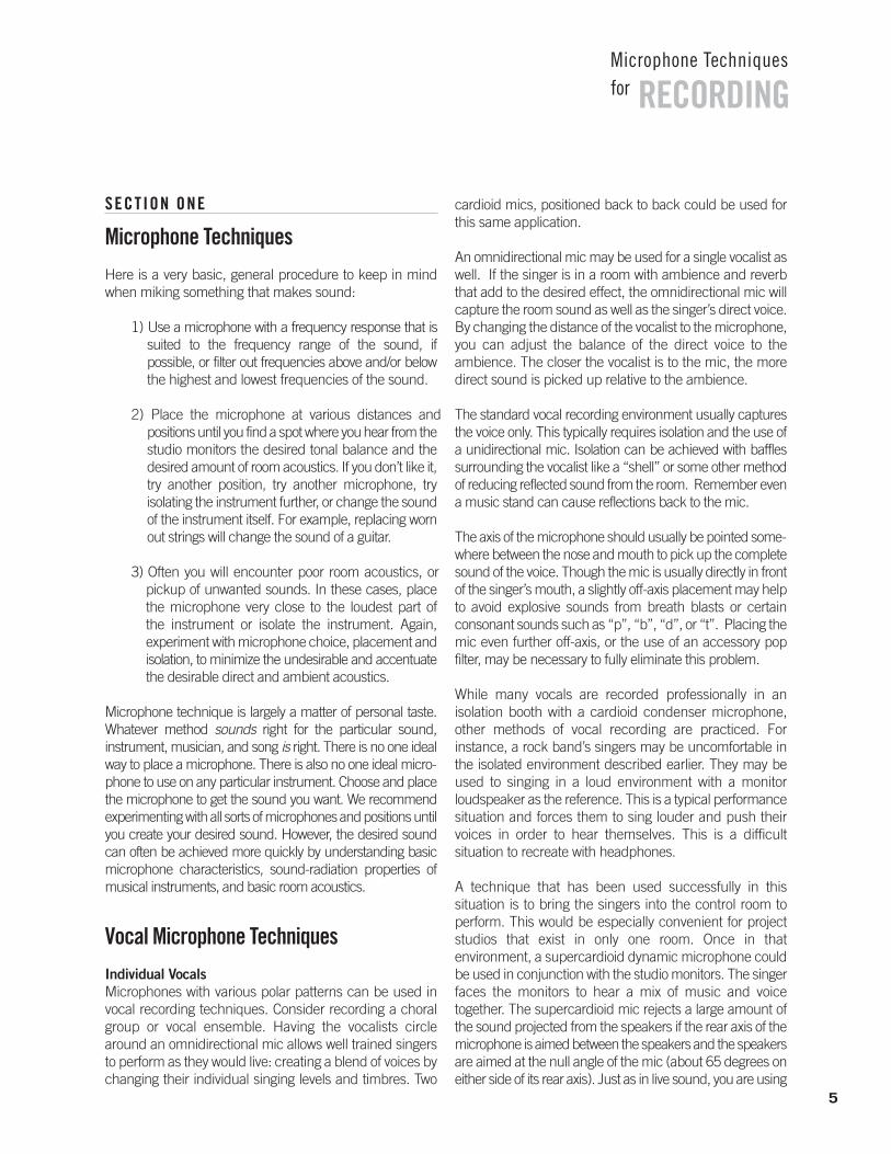
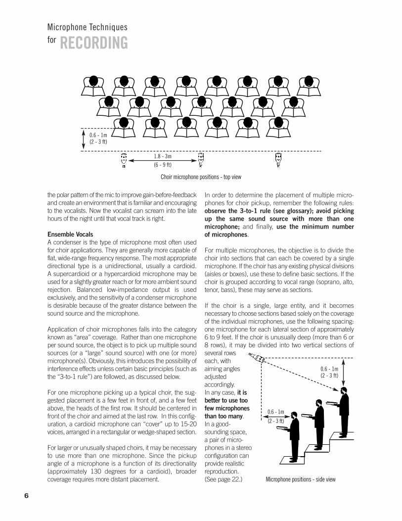
For one microphone picking up a typical choir, the sug-gested placement is a few feet in front of, and a few feetabove, the heads of the first row. It should be centered infront of the choir and aimed at the last row. In this config-uration, a cardioid microphone can “cover” up to 15-20voices, arranged in a rectangular or wedge-shaped section.
For larger or unusually shaped choirs, it may be necessaryto use more than one microphone. Since the pickup angle of a microphone is a function of its directionality (approximately 130 degrees for a cardioid), broader coverage requires more distant placement.
In order to determine the placement of multiple micro-phones for choir pickup, remember the following rules:observe the 3-to-1 rule (see glossary); avoid picking up the same sound source with more than one microphone; and finally, use the minimum number of microphones.
For multiple microphones, the objective is to divide thechoir into sections that can each be covered by a single microphone. If the choir has any existing physical divisions(aisles or boxes), use these to define basic sections. If thechoir is grouped according to vocal range (soprano, alto,tenor, bass), these may serve as sections.
If the choir is a single, large entity, and it becomes necessary to choose sections based solely on the coverageof the individual microphones, use the following spacing: one microphone for each lateral section of approximately6 to 9 feet. If the choir is unusually deep (more than 6 or8 rows), it may be divided into two vertical sections of several rows each, with aiming angles adjusted accordingly. In any case, it isbetter to use toofew microphonesthan too many. In a good-sounding space, a pair of micro-phones in a stereo configuration canprovide realisticreproduction.(See page 22.)
6
RECORDINGMicrophone Techniquesfor
0.6 - 1m(2 - 3 ft)
1.8 - 3m(6 - 9 ft)
Choir microphone positions - top view
0.6 - 1m
(2 - 3 ft)
Microphone positions - side view
0.6 - 1m(2 - 3 ft)
Spoken Word/ “Podcasting”Countless “how-to” articles have been written on podcasting, which is essentially a current trend in spoken word distribution, but few offer many tips onhow to properly record the human voice. Below aresome suggestions:
1. Keep the microphone 6 –12” from your mouth.Generally, keep the microphone as close as possibleto your mouth to avoid picking up unwanted roomreflections and reverberation. Do not get too closeeither. Proximity effect, which is an increase in lowfrequency response that occurs as you get closer toa directional microphone, can cause your voice tosound “muddy” or overly bassy.
2. Aim the microphone toward your mouth from below or above.This placement minimizes “popping” caused by plosive consonants (e.g. “p” or “t”).
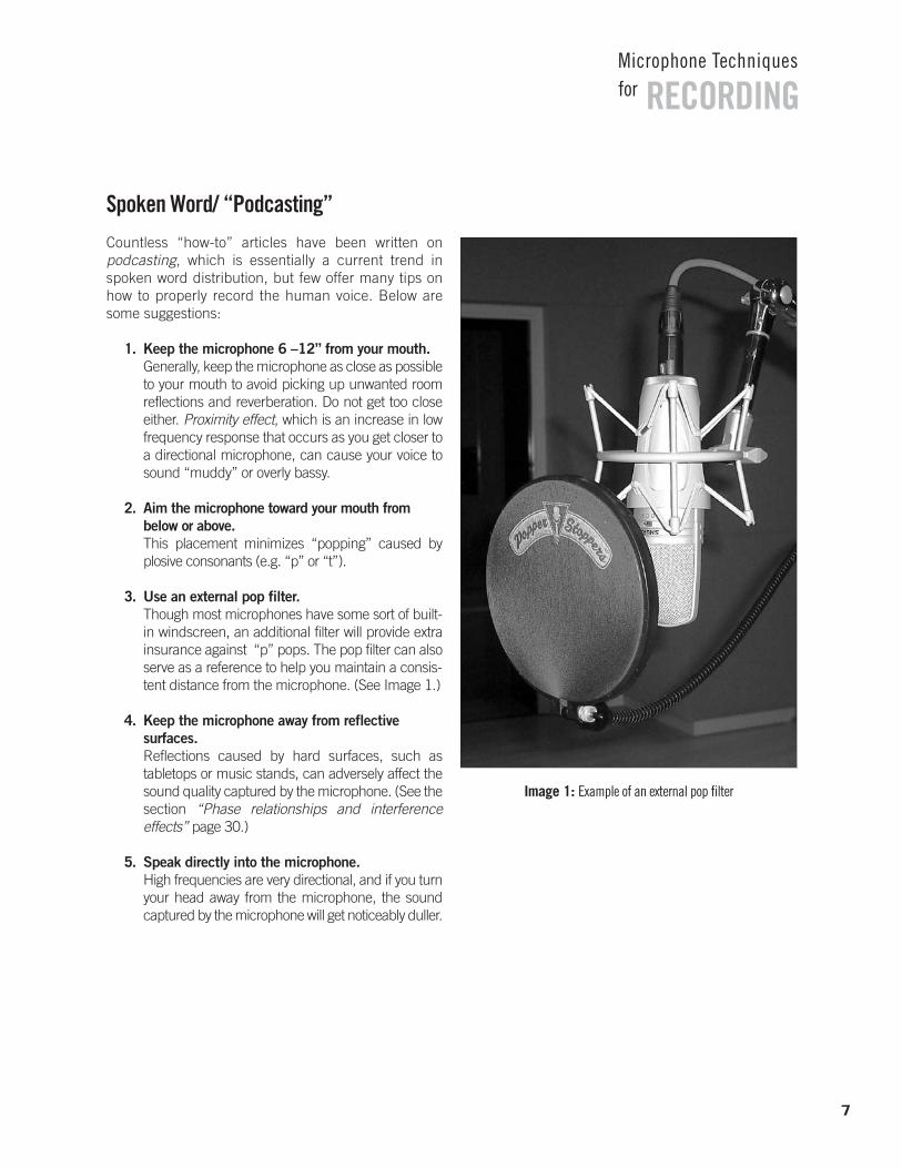
3. Use an external pop filter.Though most microphones have some sort of built-in windscreen, an additional filter will provide extrainsurance against “p” pops. The pop filter can alsoserve as a reference to help you maintain a consis-tent distance from the microphone. (See Image 1.)
4. Keep the microphone away from reflective surfaces.Reflections caused by hard surfaces, such as tabletops or music stands, can adversely affect thesound quality captured by the microphone. (See the section “Phase relationships and interference effects” page 30.)
5. Speak directly into the microphone.High frequencies are very directional, and if you turnyour head away from the microphone, the sound captured by the microphone will get noticeably duller.
RECORDINGMicrophone Techniquesfor
Image 1: Example of an external pop filter
7
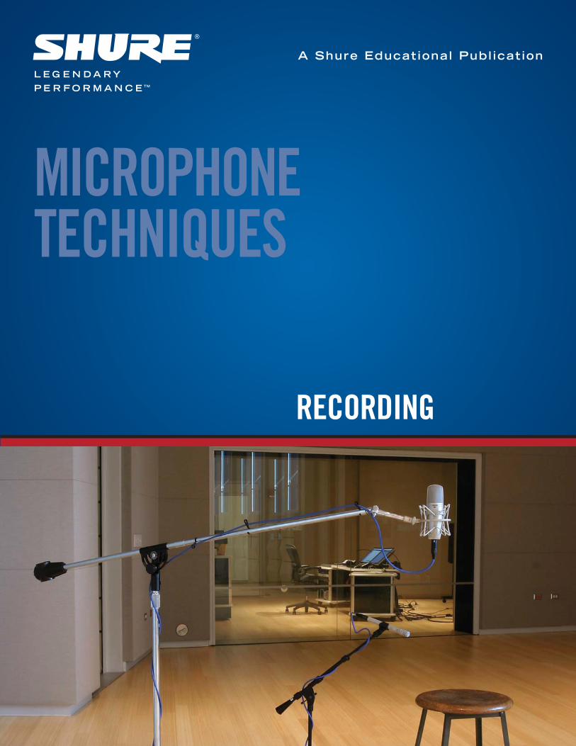
Acoustic String and Fretted InstrumentsExperimentation with mic placement provides the abilityto achieve accurate and pleasing sound reproduction onthese complex sound sources. It is also an opportunity forexploring sound manipulation, giving the studio engineermany paths to the final mix. Whether you are involved in amusic studio, a commercial studio, or a project studio, youshould continue to explore different methods of achievingthe desired results. The possibilities are limited only by timeand curiosity.
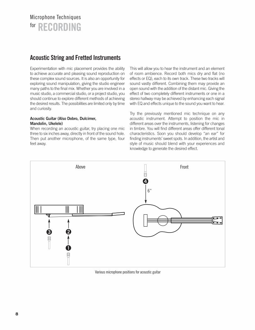
Acoustic Guitar (Also Dobro, Dulcimer, Mandolin, Ukelele)When recording an acoustic guitar, try placing one micthree to six inches away, directly in front of the sound hole.Then put another microphone, of the same type, four feet away.
This will allow you to hear the instrument and an elementof room ambience. Record both mics dry and flat (no effects or EQ), each to its own track. These two tracks willsound vastly different. Combining them may provide anopen sound with the addition of the distant mic. Giving theeffect of two completely different instruments or one in astereo hallway may be achieved by enhancing each signalwith EQ and effects unique to the sound you want to hear.
Try the previously mentioned mic technique on anyacoustic instrument. Attempt to position the mic in different areas over the instruments, listening for changesin timbre. You will find different areas offer different tonalcharacteristics. Soon you should develop “an ear” for finding instruments’ sweet spots. In addition, the artist andstyle of music should blend with your experiences andknowledge to generate the desired effect.
8
RECORDINGMicrophone Techniquesfor
Above Front
3 2
1
4
Various microphone positions for acoustic guitar
6”
9
RECORDINGMicrophone Techniquesfor
Bassy
Very bassy, boomy,muddy, full
Woody, warm, mellow. Mid-bassy,lacks detail
Natural, well-balanced,slightly bright
Natural, well-balanced
Bassy, less string noise
Bassy, thumpy
Bright
Natural
Natural
Well-defined
Bright
Good starting placement when leakage is a problem. Roll off bass for a more natural sound (more for a uni than an omni).
Very good isolation. Bass roll-off needed for a natural sound.
Reduces pick and string noise.
Less pickup of ambiance and leakage than 3 feet from sound hole.
Good isolation. Allows freedom of movement.
Reduces leakage. Test positions to find each guitar’s sweet spot.
Limits leakage. Roll off bass for natural sound.
Limits leakage.
Limits leakage. Allows freedom of movement.
Well-balanced sound.
Well-balanced sound, but little isolation.
Minimizes feedback and leakage. Allows freedom of movement.
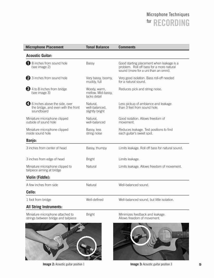
8 inches from sound hole(see image 2)
3 inches from sound hole
4 to 8 inches from bridge(see image 3)
6 inches above the side, over the bridge, and even with the frontsoundboard
Miniature microphone clipped outside of sound hole
Miniature microphone clipped inside sound hole
Banjo:
3 inches from center of head
3 inches from edge of head
Miniature microphone clipped to tailpiece aiming at bridge
Violin (Fiddle):
A few inches from side
Cello:
1 foot from bridge
All String Instruments:
Miniature microphone attached tostrings between bridge and tailpiece
Acoustic Guitar:
1
2
3
4
Microphone Placement Tonal Balance Comments
Image 2: Acoustic guitar position 1 Image 3: Acoustic guitar position 3
10
RECORDINGMicrophone Techniquesfor
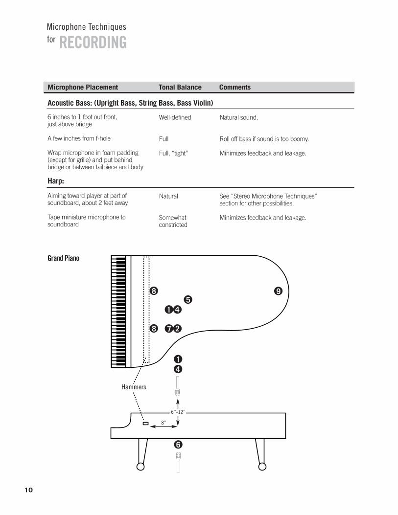
Grand Piano
Hammers
6”-12”
8
8
1 4
7 2
59
41
8”
6
Well-defined
Full
Full, “tight”
Natural
Somewhat constricted
Natural sound.
Roll off bass if sound is too boomy.
Minimizes feedback and leakage.
See “Stereo Microphone Techniques” section for other possibilities.
Minimizes feedback and leakage.
6 inches to 1 foot out front, just above bridge
A few inches from f-hole
Wrap microphone in foam padding (except for grille) and put behind bridge or between tailpiece and body
Harp:
Aiming toward player at part of soundboard, about 2 feet away
Tape miniature microphone to soundboard
Acoustic Bass: (Upright Bass, String Bass, Bass Violin)
Microphone Placement Tonal Balance Comments
11
RECORDINGMicrophone Techniquesfor
Natural, well-balanced
Natural, well-balanced,slightly bright
Thin, dull, hard, constricted
Muddy, boomy, dull, lacks attack
Bassy, full
Bassy, dull, full
Bright, well-balanced
Bright, well-balanced,strong attack
Full, natural
Less pickup of ambience and leakage than 3 feetout front. Move microphone(s) farther from hammers to reduce attack and mechanical noises.Good coincident-stereo placement. See “Stereo Microphone Techniques” section.
Place one microphone over bass strings and oneover treble strings for stereo. Phase cancellationsmay occur if the recording is heard in mono.
Very good isolation. Sometimes sounds good forrock music. Boost mid-bass and treble for morenatural sound.
Improves isolation. Bass roll-off and some trebleboost required for more natural sound.
Unobtrusive placement.
Unobtrusive placement.
Excellent isolation. Experiment with lid height and microphone placement on piano lid for desired sounds.
Excellent isolation. Moving “low” mic away fromkeyboard six inches provides truer reproduction of the bass strings while reducing damper noise.By splaying these two mics outward slightly, the overlap in the middle registers can be minimized.
Excellent isolation. Minimizes hammer anddamper noise. Best if used in conjunction with twosurface-mount microphones mounted to closedlid, as above.
12 inches above middle strings, 8 inches horizontally from hammers with lid off or at full stick
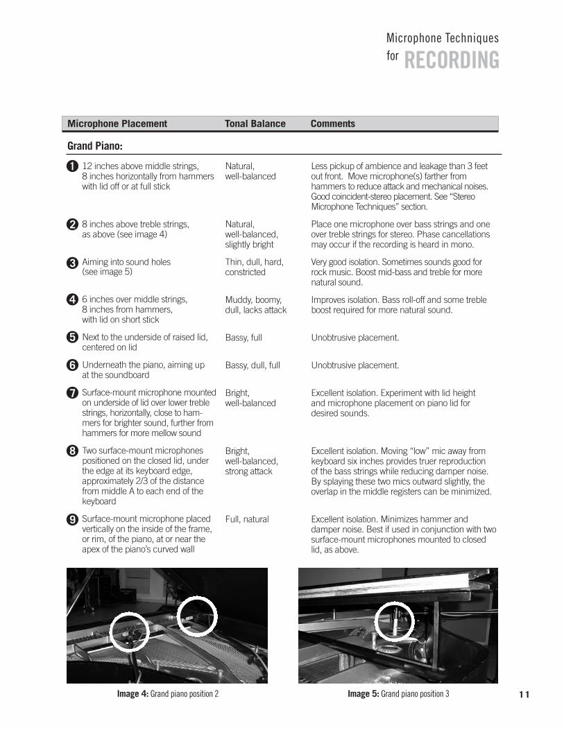
8 inches above treble strings, as above (see image 4)
Aiming into sound holes(see image 5)
6 inches over middle strings, 8 inches from hammers, with lid on short stick
Next to the underside of raised lid, centered on lid
Underneath the piano, aiming up at the soundboard
Surface-mount microphone mountedon underside of lid over lower treblestrings, horizontally, close to ham-mers for brighter sound, further fromhammers for more mellow sound
Two surface-mount microphonespositioned on the closed lid, underthe edge at its keyboard edge, approximately 2/3 of the distancefrom middle A to each end of thekeyboard
Surface-mount microphone placedvertically on the inside of the frame,or rim, of the piano, at or near theapex of the piano’s curved wall
Grand Piano:
Microphone Placement Tonal Balance Comments
1
2
3
4
5
6
7
8
9
Image 4: Grand piano position 2 Image 5: Grand piano position 3
12
RECORDINGMicrophone Techniquesfor
Natural (but lacksdeep bass), picks uphammer attack
Slightly full or tubby,picks up hammer attack
Natural, picks uphammer attack
Full, slightly tubby,no hammer attack
Thin, constricted, no hammer attack
Bright, picks uphammer attack
Natural,good presence
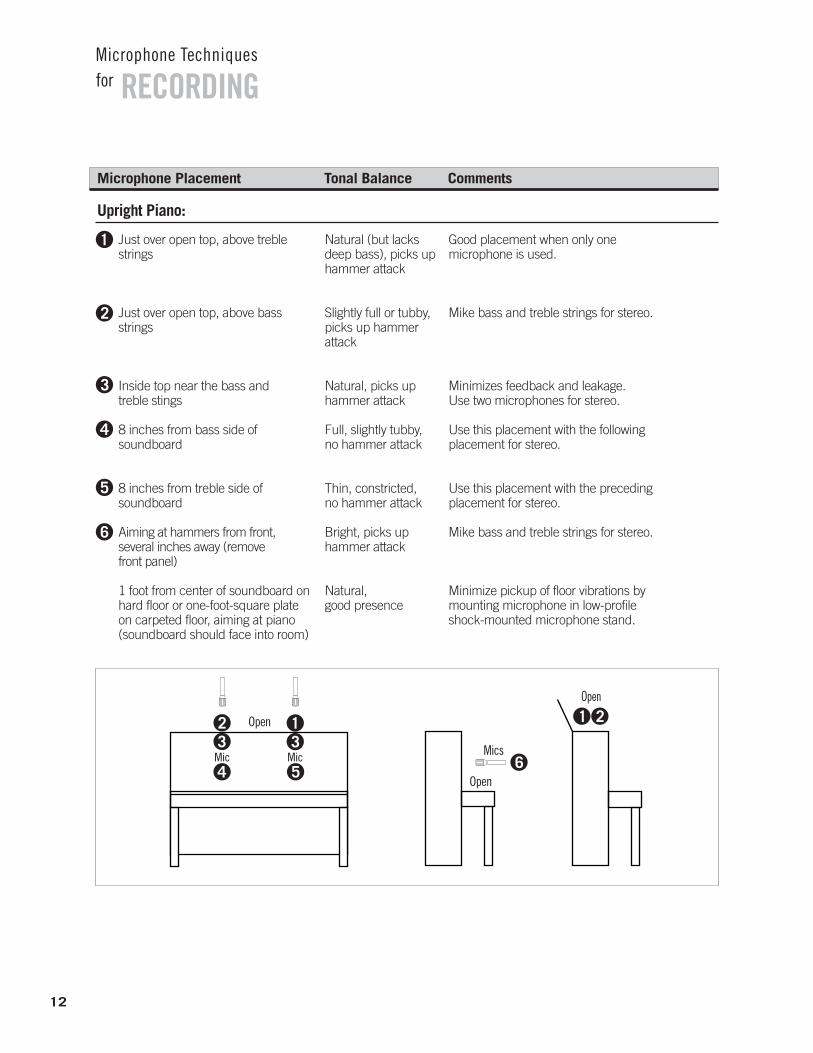
Just over open top, above treblestrings
Just over open top, above bassstrings
Inside top near the bass and treble stings
8 inches from bass side of soundboard
8 inches from treble side of soundboard
Aiming at hammers from front, several inches away (remove front panel)
1 foot from center of soundboard onhard floor or one-foot-square plateon carpeted floor, aiming at piano(soundboard should face into room)
Upright Piano:
Microphone Placement Tonal Balance Comments
1
2
3
4
5
6
Open
4 5
32
Mic31
Mic Mics6
1 2Open
Open
Good placement when only one microphone is used.
Mike bass and treble strings for stereo.
Minimizes feedback and leakage. Use two microphones for stereo.
Use this placement with the following placement for stereo.
Use this placement with the preceding placement for stereo.
Mike bass and treble strings for stereo.
Minimize pickup of floor vibrations by mounting microphone in low-profile shock-mounted microphone stand.
13
RECORDINGMicrophone Techniquesfor
Bright
Warm, full
Natural
Bright, punchy
Minimizes feedback and leakage.
Picks up fingering noise.
Good recording technique.
Maximum isolation, up-front sound.
A few inches from and aiming into bell
A few inches from sound holes
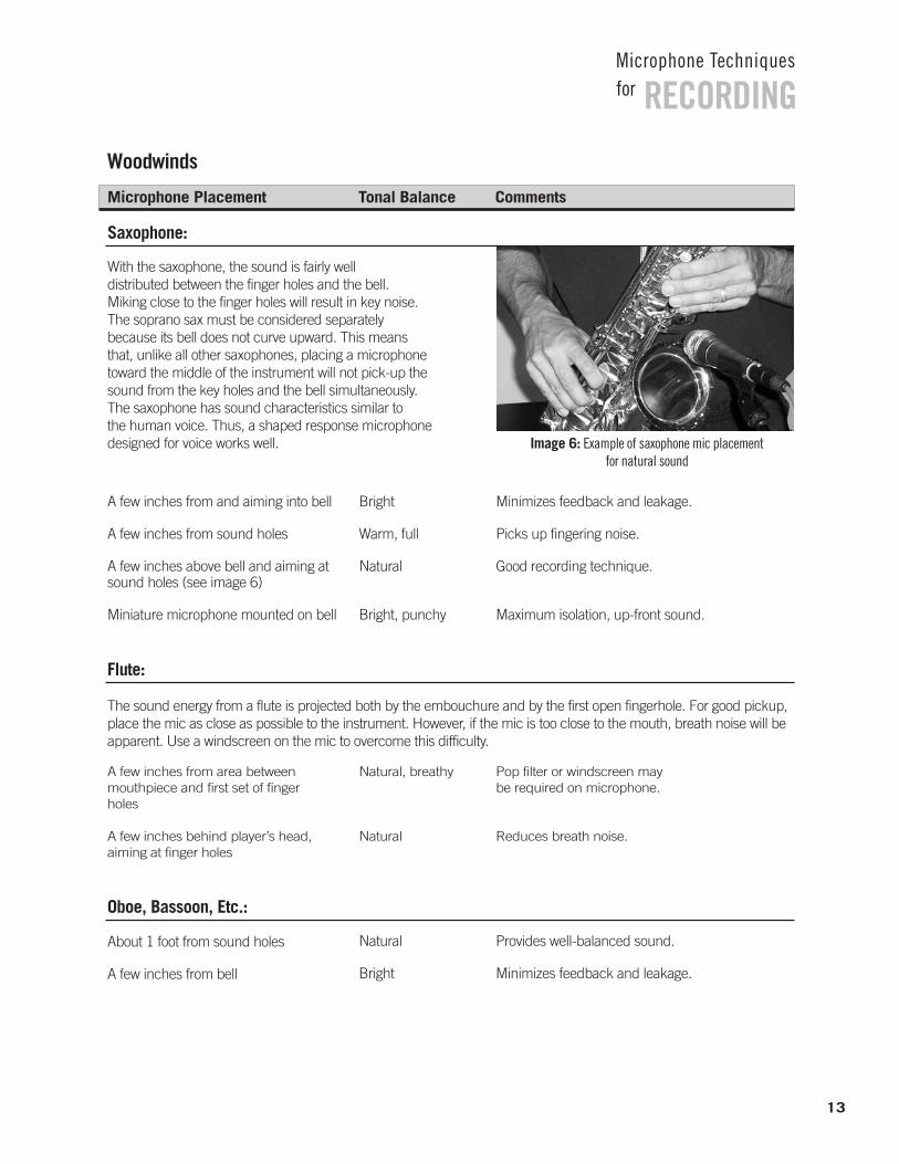
A few inches above bell and aiming atsound holes (see image 6)
Miniature microphone mounted on bell
Saxophone:
Microphone Placement Tonal Balance Comments
Flute:
The sound energy from a flute is projected both by the embouchure and by the first open fingerhole. For good pickup,place the mic as close as possible to the instrument. However, if the mic is too close to the mouth, breath noise will beapparent. Use a windscreen on the mic to overcome this difficulty.
With the saxophone, the sound is fairly well distributed between the finger holes and the bell. Miking close to the finger holes will result in key noise. The soprano sax must be considered separately because its bell does not curve upward. This means that, unlike all other saxophones, placing a microphonetoward the middle of the instrument will not pick-up thesound from the key holes and the bell simultaneously.The saxophone has sound characteristics similar to the human voice. Thus, a shaped response microphonedesigned for voice works well.
Woodwinds
Natural, breathy
Natural
Pop filter or windscreen may be required on microphone.
Reduces breath noise.
A few inches from area betweenmouthpiece and first set of fingerholes
A few inches behind player’s head,aiming at finger holes
Natural
Bright
Provides well-balanced sound.
Minimizes feedback and leakage.
Oboe, Bassoon, Etc.:
About 1 foot from sound holes
A few inches from bell
Image 6: Example of saxophone mic placement for natural sound
14
RECORDINGMicrophone Techniquesfor
Microphone Placement Tonal Balance Comments
Woodwinds (continued)
Full, bright Minimizes feedback and leakage. Microphone may be cupped in hands.
Very close to instrument
Harmonica:
Full range, natural sound
Emphasizesmidrange
Use two microphones for stereo or to pick upbass and treble sides separately.
Minimizes leakage. Allows freedom of movement.
One or two feet in front of instrument,centered
Miniature microphone mountedinternally
Accordion:
Microphone Placement Tonal Balance Comments
Brass
On-axis to bellsounds bright; to one side sounds natural or mellow
Bright
Close miking sounds “tight” and minimizes feedback and leakage. More distant placementgives fuller, more dramatic sound.
Maximum isolation.
1 to 2 feet from bell (a couple of instruments can play into one microphone)
Miniature microphone mounted on bell
Trumpet, Cornet Trombone, Tuba:
Natural Watch out for extreme fluctuations on VU meter.Microphone aiming toward bell
French Horn:
The sound from most brass instruments is very directional. Placing the mic off axis with the bell of the instrument willresult in less pickup of high frequencies.
15
RECORDINGMicrophone Techniquesfor
Amplified Instruments
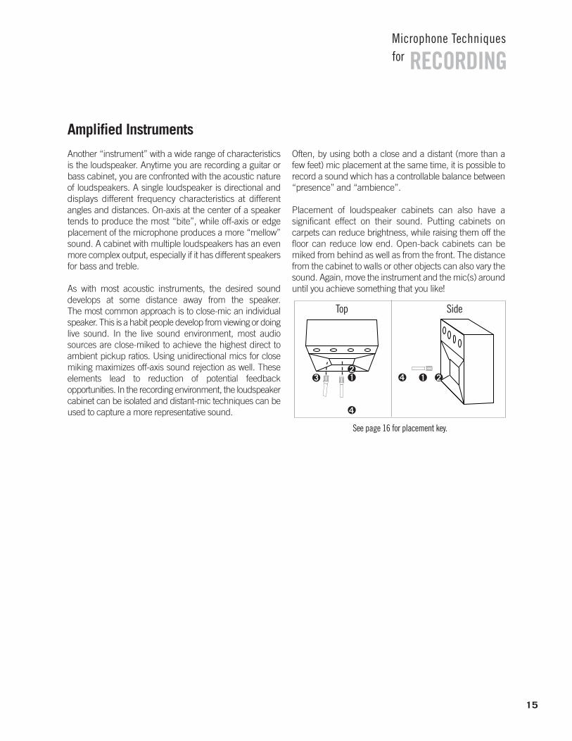
Another “instrument” with a wide range of characteristicsis the loudspeaker. Anytime you are recording a guitar orbass cabinet, you are confronted with the acoustic natureof loudspeakers. A single loudspeaker is directional anddisplays different frequency characteristics at different angles and distances. On-axis at the center of a speakertends to produce the most “bite”, while off-axis or edgeplacement of the microphone produces a more “mellow”sound. A cabinet with multiple loudspeakers has an evenmore complex output, especially if it has different speakersfor bass and treble.
As with most acoustic instruments, the desired sound develops at some distance away from the speaker. The most common approach is to close-mic an individualspeaker. This is a habit people develop from viewing or doinglive sound. In the live sound environment, most audiosources are close-miked to achieve the highest direct to ambient pickup ratios. Using unidirectional mics for closemiking maximizes off-axis sound rejection as well. These elements lead to reduction of potential feedback opportunities. In the recording environment, the loudspeakercabinet can be isolated and distant-mic techniques can beused to capture a more representative sound.
Often, by using both a close and a distant (more than afew feet) mic placement at the same time, it is possible torecord a sound which has a controllable balance between“presence” and “ambience”.
Placement of loudspeaker cabinets can also have a significant effect on their sound. Putting cabinets on carpets can reduce brightness, while raising them off thefloor can reduce low end. Open-back cabinets can bemiked from behind as well as from the front. The distancefrom the cabinet to walls or other objects can also vary thesound. Again, move the instrument and the mic(s) arounduntil you achieve something that you like!
Top Side
213 4
4
1 2
See page 16 for placement key.
16
RECORDINGMicrophone Techniquesfor
Microphone Placement Tonal Balance Comments
Natural, well-balanced
Bassy
Dull or mellow
Thin, reduced bass
Natural
Emphasizedmidrange
Depends on position
Small microphone desk stand may be used ifloudspeaker is close to floor.
Minimizes feedback and leakage.
Microphone closer to edge of speaker cone resultsin duller sound. Reduces amplifier hiss noise.
Picks up more room ambiance and leakage.
Use condenser microphone for position 4 – adjust spacing to minimize phase issues.
Easy setup, minimizes leakage.
Can be combined with mic in front of cabinet, but be careful of phase cancellation.
4 inches from grille cloth at center of speaker cone
1 inch from grille cloth at center of speaker cone
Off-center with respect to speaker cone
3 feet from center of speaker cone
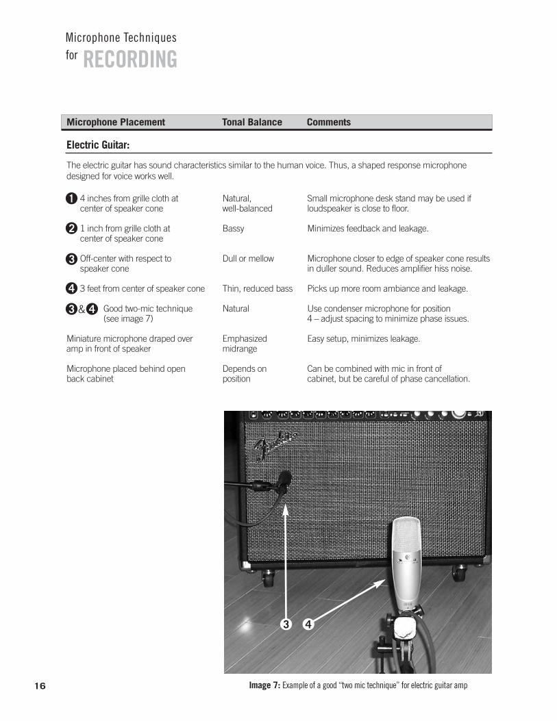
Good two-mic technique (see image 7)
Miniature microphone draped overamp in front of speaker
Microphone placed behind open back cabinet
Electric Guitar:
The electric guitar has sound characteristics similar to the human voice. Thus, a shaped response microphonedesigned for voice works well.
1
2
3
4
3 4&
Image 7: Example of a good “two mic technique” for electric guitar amp
3 4
17
RECORDINGMicrophone Techniquesfor
Bass Guitar:If the cabinet has only one speaker a single microphoneshould pick up a suitable sound with a little experimentation. If the cabinet has multiple speakers ofthe same type it is typically easiest to place the microphoneto pick up just one speaker.
Placing the microphone between speakers can result instrong phase effects though this may be desirable toachieve a particular tone. However, if the cabinet is stereoor has separate bass and treble speakers multiple microphones may be required.
Microphone Placement Tonal Balance Comments
Depends on brand of piano
Roll off bass for clarity, roll off highfrequencies to reduce hiss.
Aim microphone at speaker as described in Electric Guitar Amplifier section
Electric Keyboard Amp:
Natural, lacks deep bass
Natural, well-balanced
Natural, well-balanced
Good one-microphone pickup.
Excellent overall sound.
Stereo effect.
Aim one microphone into top louvers 3 inches to 1 foot away
Mike top louvers and bottom bassspeaker 3 inches to 1 foot away
Mike top louvers with two microphones, one close to each side;pan to left and right; mike bottom bass speaker 3 inches to 1 foot awayand pan its signal to center
Leslie Organ Speaker:
Drums and Percussion
Drum Kit Miking – The drum kit is one of the most complicated sound sources to record. Although there aremany different methods, some common techniques andprinciples should be understood. Since the different partsof the drum kit have widely varying sound they should be considered as individual instruments, or at least a smallgroup of instrument types: Kick, Snare, Toms, Cymbals,and Percussion. Certain mic characteristics are extremelycritical for drum usage.
Dynamic Range – A drum can produce very high SoundPressure Levels (SPLs). The microphone must be able tohandle these levels. A dynamic microphone will usuallyhandle high SPLs better than a condenser. Check theMaximum SPL in condenser microphone specifications.It should be at least 130 dB for closeup drum use.
Directionality – Because we want to consider each part ofthe kit an individual instrument; each drum may have itsown mic. Interference effects may occur due to the closeproximity of the mics to each other and to the variousdrums. Choosing mics that can reject sound at certain an-gles and placing them properly can be pivotal in achievingan overall drum mix with minimal phase problems.
Proximity Effect – Unidirectional mics may have excessivelow frequency response when placed very close to thedrums. A low frequency roll-off either on the microphoneor at the mixer will help cure a “muddied” sound. However,proximity effect may also enhance low frequency responseif desired. It can also be used to effectively reduce pickupof distant low frequency sources by the amount of low-rolloff used to control the closeup source. Typically, drumsare isolated in their own room to prevent bleed through tomicrophones on other instruments. In professional studiosit is common for the drums to be raised above the floor. Thishelps reduce low frequency transmission through the floor.
Here is a basic individual drum miking technique:
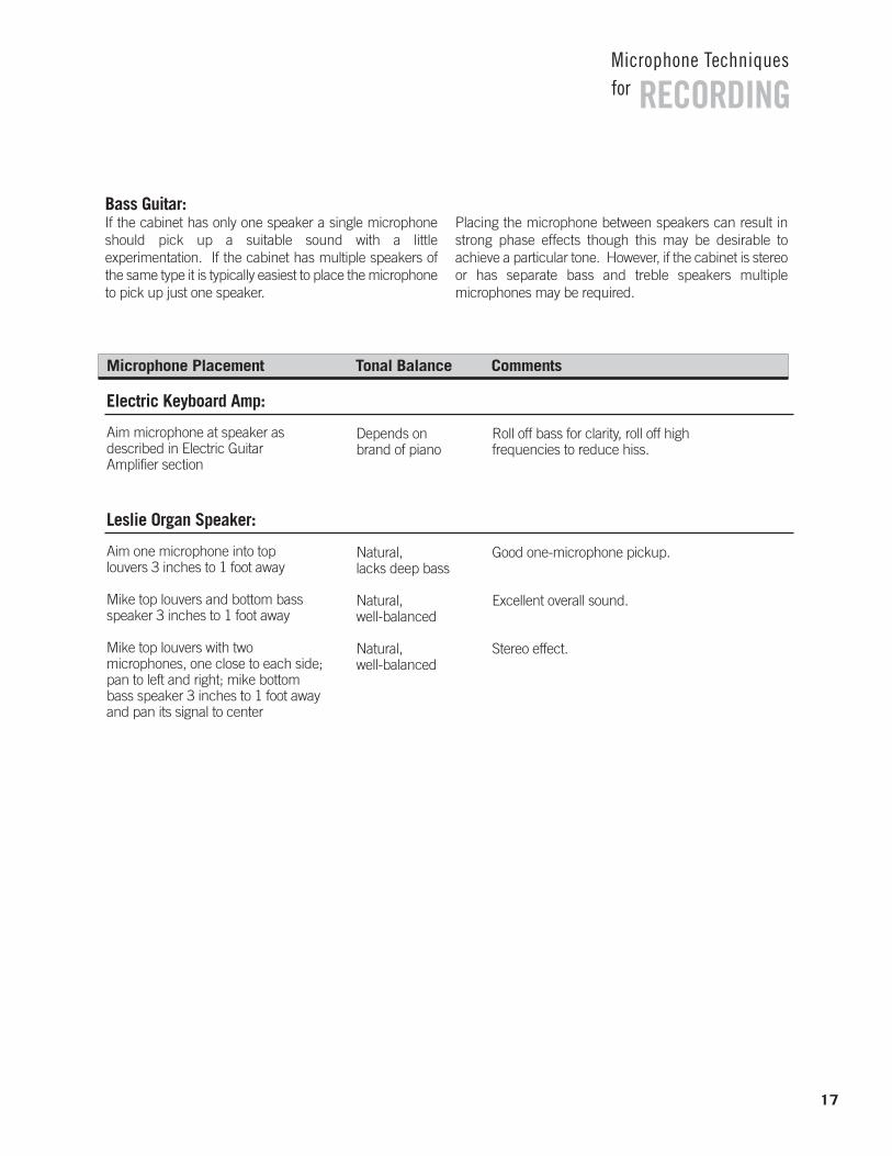
Bass (Kick) Drums – This drum’s purpose in mostmusic is to provide transient, low-frequency energy burststhat help establish the primary rhythmic pattern of a song.The kick drum’s energy is primarily focused in two areas:very low-end timbre and “attack”. Although this varies by individual drum, the attack tends to be in the 2.5-5kHz range.
A microphone for this use should have good low frequencyresponse and possibly a boost in the attack range, although this can be done easily with EQ. The mic should beplaced in the drum, in close proximity (1 - 6 inches), facingthe beater head. (See position D in diagram on the followingpage.) Or for less “slap” just inside the hole. (See image 8.)
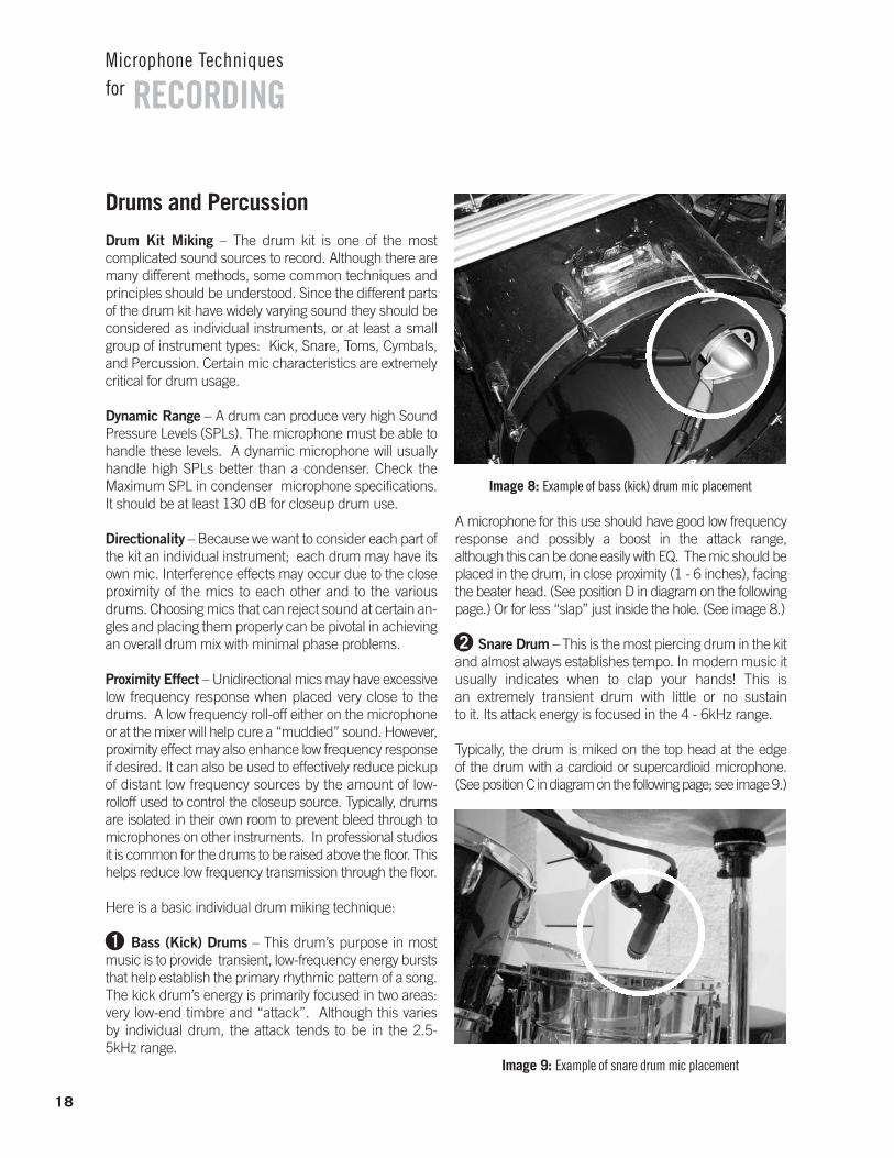
Snare Drum – This is the most piercing drum in the kitand almost always establishes tempo. In modern music itusually indicates when to clap your hands! This is an extremely transient drum with little or no sustain to it. Its attack energy is focused in the 4 - 6kHz range.
Typically, the drum is miked on the top head at the edge of the drum with a cardioid or supercardioid microphone. (See position C in diagram on the following page; see image 9.)
18
RECORDINGMicrophone Techniquesfor
Image 8: Example of bass (kick) drum mic placement
Image 9: Example of snare drum mic placement
1
2
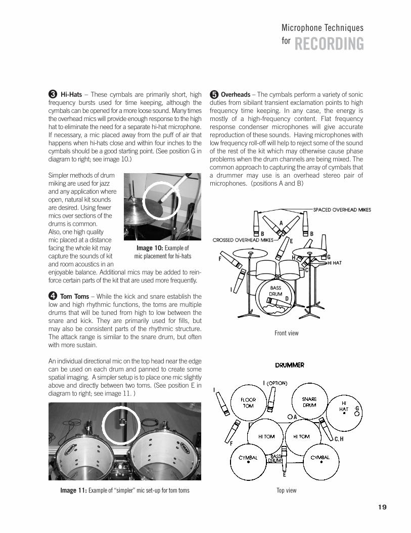
Hi-Hats – These cymbals are primarily short, high frequency bursts used for time keeping, although the cymbals can be opened for a more loose sound. Many timesthe overhead mics will provide enough response to the highhat to eliminate the need for a separate hi-hat microphone.If necessary, a mic placed away from the puff of air that happens when hi-hats close and within four inches to thecymbals should be a good starting point. (See position G indiagram to right; see image 10.)
Simpler methods of drummiking are used for jazzand any application whereopen, natural kit soundsare desired. Using fewermics over sections of thedrums is common.Also, one high quality mic placed at a distancefacing the whole kit maycapture the sounds of kitand room acoustics in an enjoyable balance. Additional mics may be added to rein-force certain parts of the kit that are used more frequently.
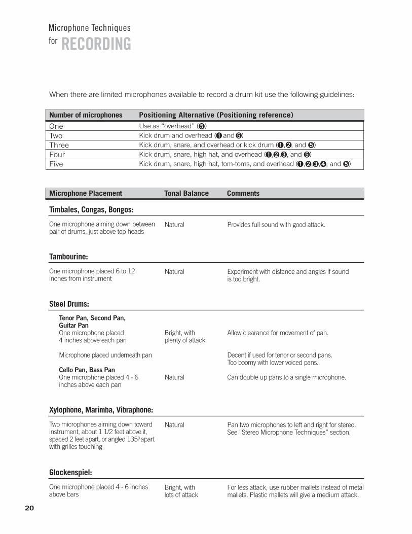
Tom Toms – While the kick and snare establish thelow and high rhythmic functions, the toms are multipledrums that will be tuned from high to low between thesnare and kick. They are primarily used for fills, but may also be consistent parts of the rhythmic structure. The attack range is similar to the snare drum, but oftenwith more sustain.
An individual directional mic on the top head near the edgecan be used on each drum and panned to create somespatial imaging. A simpler setup is to place one mic slightlyabove and directly between two toms. (See position E indiagram to right; see image 11. )
Overheads – The cymbals perform a variety of sonic duties from sibilant transient exclamation points to highfrequency time keeping. In any case, the energy is mostly of a high-frequency content. Flat frequency response condenser microphones will give accurate reproduction of these sounds. Having microphones withlow frequency roll-off will help to reject some of the soundof the rest of the kit which may otherwise cause phaseproblems when the drum channels are being mixed. Thecommon approach to capturing the array of cymbals thata drummer may use is an overhead stereo pair of microphones. (positions A and B)
19
RECORDINGMicrophone Techniquesfor
3
Image 10: Example of mic placement for hi-hats
4
Image 11: Example of “simpler” mic set-up for tom toms
Front view
Top view
5
A
BB
C
D
E
F GH
I
A
E
C H
G
F
II
20
RECORDINGMicrophone Techniquesfor
When there are limited microphones available to record a drum kit use the following guidelines:
Number of microphones Positioning Alternative (Positioning reference)
OneTwoThreeFourFive
Use as “overhead” ( )Kick drum and overhead ( and )Kick drum, snare, and overhead or kick drum ( , , and )Kick drum, snare, high hat, and overhead ( , , , and )Kick drum, snare, high hat, tom-toms, and overhead ( , , , , and )
5
1 5
1 2 5
1 2 3 5
1 2 3 4 5
Microphone Placement Tonal Balance Comments
Natural Provides full sound with good attack.One microphone aiming down betweenpair of drums, just above top heads
Timbales, Congas, Bongos:
Natural Experiment with distance and angles if soundis too bright.
One microphone placed 6 to 12inches from instrument
Tambourine:
Bright, with plenty of attack
Natural
Allow clearance for movement of pan.
Decent if used for tenor or second pans. Too boomy with lower voiced pans.
Can double up pans to a single microphone.
Tenor Pan, Second Pan, Guitar PanOne microphone placed 4 inches above each pan
Microphone placed underneath pan
Cello Pan, Bass PanOne microphone placed 4 - 6 inches above each pan
Steel Drums:
Natural Pan two microphones to left and right for stereo.See “Stereo Microphone Techniques” section.
Two microphones aiming down towardinstrument, about 1 1/2 feet above it,spaced 2 feet apart, or angled 1350 apartwith grilles touching
Xylophone, Marimba, Vibraphone:
Bright, with lots of attack
For less attack, use rubber mallets instead of metalmallets. Plastic mallets will give a medium attack.
One microphone placed 4 - 6 inchesabove bars
Glockenspiel:
Stereo
Stereo Microphone Techniques – One of the most popularspecialized microphone techniques is stereo miking. This use of two or more microphones to create a stereoimage will often give depth and spatial placement to an instrument or overall recording. There are a number of different methods for stereo. Three of the most popular arethe spaced pair (A/B), the coincident or near-coincident pair(X-Y configuration), and the Mid-Side (M-S) technique.
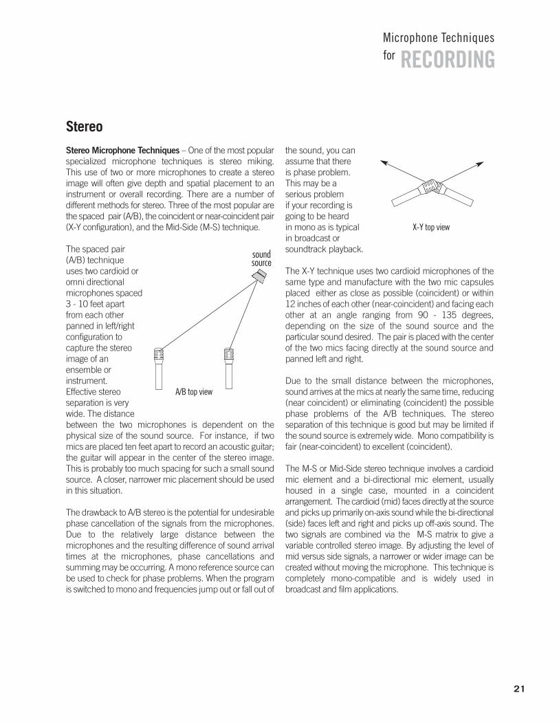
The spaced pair(A/B) technique uses two cardioid oromni directional microphones spaced3 - 10 feet apart from each otherpanned in left/right configuration to capture the stereoimage of an ensemble or instrument. Effective stereo separation is verywide. The distance between the two microphones is dependent on the physical size of the sound source. For instance, if twomics are placed ten feet apart to record an acoustic guitar;the guitar will appear in the center of the stereo image. This is probably too much spacing for such a small soundsource. A closer, narrower mic placement should be usedin this situation.
The drawback to A/B stereo is the potential for undesirablephase cancellation of the signals from the microphones.Due to the relatively large distance between the microphones and the resulting difference of sound arrivaltimes at the microphones, phase cancellations and summing may be occurring. A mono reference source canbe used to check for phase problems. When the programis switched to mono and frequencies jump out or fall out of
the sound, you can assume that there is phase problem. This may be a serious problem if your recording isgoing to be heard in mono as is typical in broadcast or soundtrack playback.
The X-Y technique uses two cardioid microphones of thesame type and manufacture with the two mic capsulesplaced either as close as possible (coincident) or within12 inches of each other (near-coincident) and facing eachother at an angle ranging from 90 - 135 degrees, depending on the size of the sound source and the particular sound desired. The pair is placed with the centerof the two mics facing directly at the sound source andpanned left and right.
Due to the small distance between the microphones,sound arrives at the mics at nearly the same time, reducing(near coincident) or eliminating (coincident) the possiblephase problems of the A/B techniques. The stereo separation of this technique is good but may be limited ifthe sound source is extremely wide. Mono compatibility isfair (near-coincident) to excellent (coincident).
The M-S or Mid-Side stereo technique involves a cardioidmic element and a bi-directional mic element, usuallyhoused in a single case, mounted in a coincident arrangement. The cardioid (mid) faces directly at the sourceand picks up primarily on-axis sound while the bi-directional(side) faces left and right and picks up off-axis sound. Thetwo signals are combined via the M-S matrix to give a variable controlled stereo image. By adjusting the level ofmid versus side signals, a narrower or wider image can becreated without moving the microphone. This technique iscompletely mono-compatible and is widely used in broadcast and film applications.
21
RECORDINGMicrophone Techniquesfor
A/B top view
soundsource
X-Y top view
22
RECORDINGMicrophone Techniquesfor
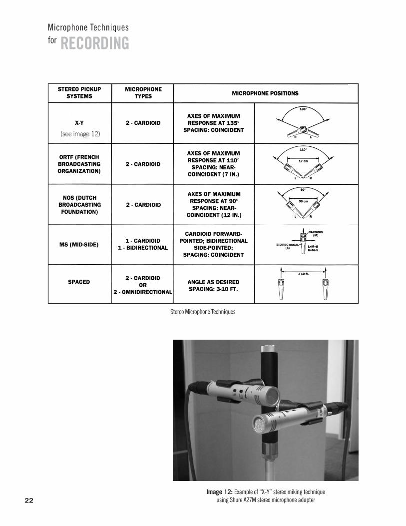
Stereo Microphone Techniques
Image 12: Example of “X-Y” stereo miking technique using Shure A27M stereo microphone adapter
(see image 12)
23
RECORDINGMicrophone Techniquesfor
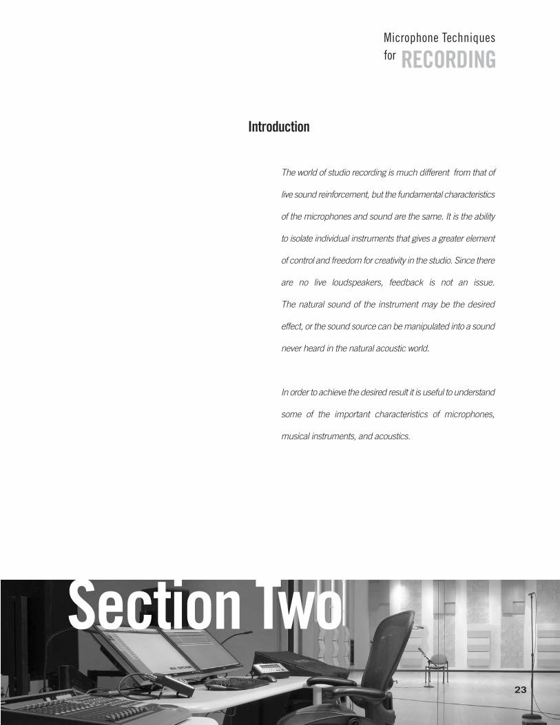
Introduction
The world of studio recording is much different from that of
live sound reinforcement, but the fundamental characteristics
of the microphones and sound are the same. It is the ability
to isolate individual instruments that gives a greater element
of control and freedom for creativity in the studio. Since there
are no live loudspeakers, feedback is not an issue.
The natural sound of the instrument may be the desired
effect, or the sound source can be manipulated into a sound
never heard in the natural acoustic world.
In order to achieve the desired result it is useful to understand
some of the important characteristics of microphones,
musical instruments, and acoustics.
Section Two
SECTION TWO
Microphone CharacteristicsThere are three main considerations when choosing a microphone for recording applications: operating principle, frequency response, and directionality.
Operating Principle – A microphone is an example of atransducer, a device which changes energy from one forminto another, in this case from acoustic into electrical. The type of transducer is defined by the operating principle. In the current era of recording, the two primaryoperating principles used in microphone design are thedynamic and the condenser.
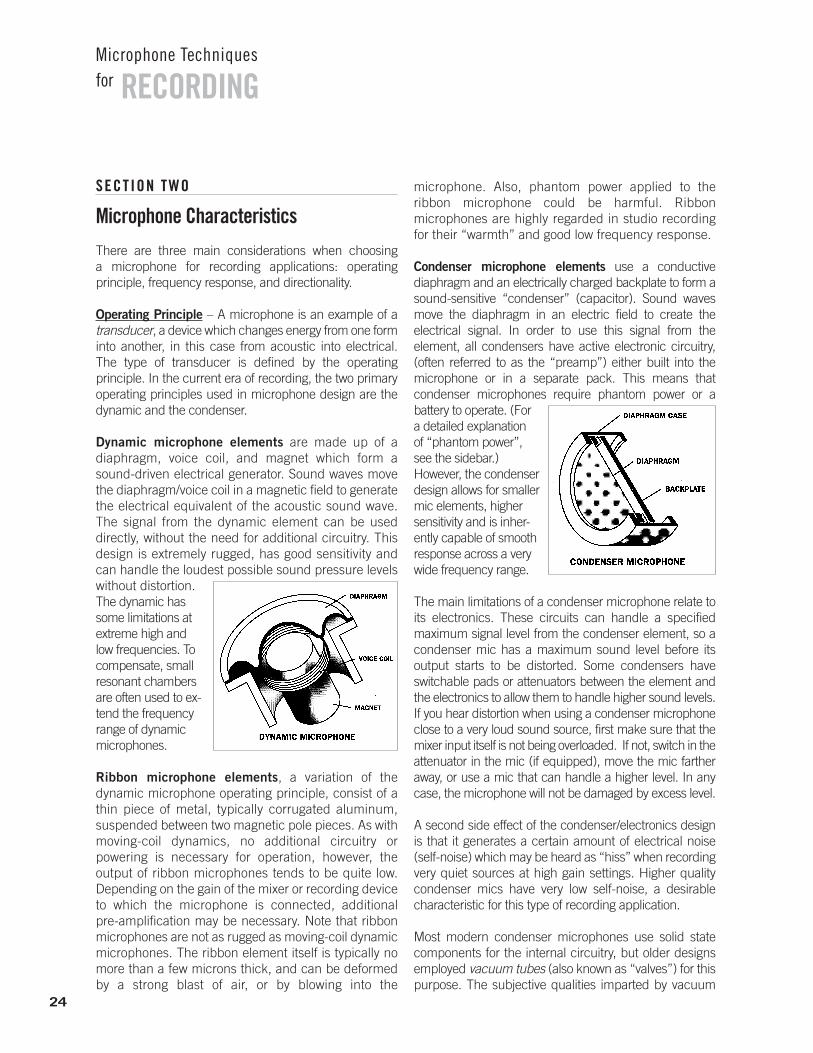
Dynamic microphone elements are made up of a diaphragm, voice coil, and magnet which form asound-driven electrical generator. Sound waves movethe diaphragm/voice coil in a magnetic field to generatethe electrical equivalent of the acoustic sound wave.The signal from the dynamic element can be used directly, without the need for additional circuitry. Thisdesign is extremely rugged, has good sensitivity andcan handle the loudest possible sound pressure levelswithout distortion. The dynamic hassome limitations atextreme high andlow frequencies. Tocompensate, smallresonant chambersare often used to ex-tend the frequencyrange of dynamicmicrophones.
Ribbon microphone elements, a variation of the dynamic microphone operating principle, consist of athin piece of metal, typically corrugated aluminum, suspended between two magnetic pole pieces. As withmoving-coil dynamics, no additional circuitry or powering is necessary for operation, however, the output of ribbon microphones tends to be quite low.Depending on the gain of the mixer or recording deviceto which the microphone is connected, additional pre-amplification may be necessary. Note that ribbonmicrophones are not as rugged as moving-coil dynamicmicrophones. The ribbon element itself is typically nomore than a few microns thick, and can be deformedby a strong blast of air, or by blowing into the
microphone. Also, phantom power applied to the ribbon microphone could be harmful. Ribbon microphones are highly regarded in studio recordingfor their “warmth” and good low frequency response.
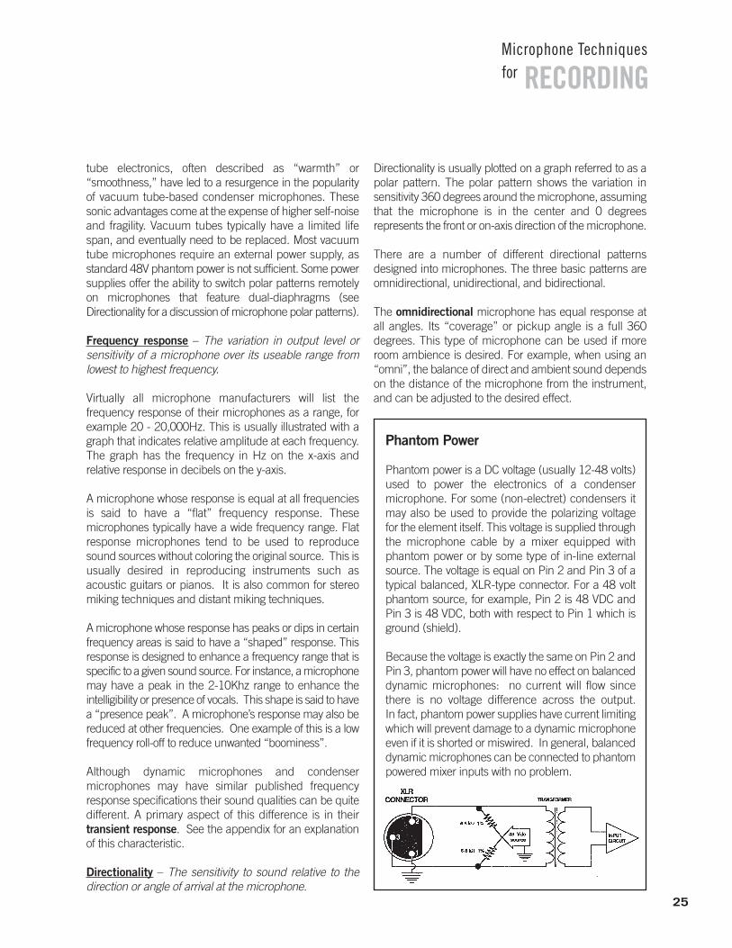
Condenser microphone elements use a conductive diaphragm and an electrically charged backplate to form asound-sensitive “condenser” (capacitor). Sound wavesmove the diaphragm in an electric field to create the electrical signal. In order to use this signal from the element, all condensers have active electronic circuitry, (often referred to as the “preamp”) either built into the microphone or in a separate pack. This means that condenser microphones require phantom power or abattery to operate. (Fora detailed explanation of “phantom power”, see the sidebar.) However, the condenserdesign allows for smallermic elements, highersensitivity and is inher-ently capable of smoothresponse across a verywide frequency range.
The main limitations of a condenser microphone relate toits electronics. These circuits can handle a specified maximum signal level from the condenser element, so acondenser mic has a maximum sound level before its output starts to be distorted. Some condensers haveswitchable pads or attenuators between the element andthe electronics to allow them to handle higher sound levels.If you hear distortion when using a condenser microphoneclose to a very loud sound source, first make sure that themixer input itself is not being overloaded. If not, switch in theattenuator in the mic (if equipped), move the mic fartheraway, or use a mic that can handle a higher level. In anycase, the microphone will not be damaged by excess level.
A second side effect of the condenser/electronics designis that it generates a certain amount of electrical noise (self-noise) which may be heard as “hiss” when recordingvery quiet sources at high gain settings. Higher quality condenser mics have very low self-noise, a desirable characteristic for this type of recording application.
Most modern condenser microphones use solid state components for the internal circuitry, but older designs employed vacuum tubes (also known as “valves”) for thispurpose. The subjective qualities imparted by vacuum
24
RECORDINGMicrophone Techniquesfor
tube electronics, often described as “warmth” or “smoothness,” have led to a resurgence in the popularityof vacuum tube-based condenser microphones. Thesesonic advantages come at the expense of higher self-noiseand fragility. Vacuum tubes typically have a limited lifespan, and eventually need to be replaced. Most vacuumtube microphones require an external power supply, asstandard 48V phantom power is not sufficient. Some powersupplies offer the ability to switch polar patterns remotelyon microphones that feature dual-diaphragms (see Directionality for a discussion of microphone polar patterns).
Frequency response – The variation in output level or sensitivity of a microphone over its useable range from lowest to highest frequency.
Virtually all microphone manufacturers will list the frequency response of their microphones as a range, forexample 20 - 20,000Hz. This is usually illustrated with agraph that indicates relative amplitude at each frequency.The graph has the frequency in Hz on the x-axis and relative response in decibels on the y-axis.
A microphone whose response is equal at all frequenciesis said to have a “flat” frequency response. These microphones typically have a wide frequency range. Flatresponse microphones tend to be used to reproducesound sources without coloring the original source. This isusually desired in reproducing instruments such asacoustic guitars or pianos. It is also common for stereomiking techniques and distant miking techniques.
A microphone whose response has peaks or dips in certainfrequency areas is said to have a “shaped” response. Thisresponse is designed to enhance a frequency range that isspecific to a given sound source. For instance, a microphonemay have a peak in the 2-10Khz range to enhance the intelligibility or presence of vocals. This shape is said to havea “presence peak”. A microphone’s response may also bereduced at other frequencies. One example of this is a lowfrequency roll-off to reduce unwanted “boominess”.
Although dynamic microphones and condenser microphones may have similar published frequency response specifications their sound qualities can be quitedifferent. A primary aspect of this difference is in their transient response. See the appendix for an explanationof this characteristic.
Directionality – The sensitivity to sound relative to the direction or angle of arrival at the microphone.
Directionality is usually plotted on a graph referred to as apolar pattern. The polar pattern shows the variation in sensitivity 360 degrees around the microphone, assumingthat the microphone is in the center and 0 degrees represents the front or on-axis direction of the microphone.
There are a number of different directional patterns designed into microphones. The three basic patterns areomnidirectional, unidirectional, and bidirectional.
The omnidirectional microphone has equal response at all angles. Its “coverage” or pickup angle is a full 360 degrees. This type of microphone can be used if moreroom ambience is desired. For example, when using an“omni”, the balance of direct and ambient sound dependson the distance of the microphone from the instrument,and can be adjusted to the desired effect.
RECORDINGMicrophone Techniquesfor
Phantom Power
Phantom power is a DC voltage (usually 12-48 volts)used to power the electronics of a condenser microphone. For some (non-electret) condensers itmay also be used to provide the polarizing voltage for the element itself. This voltage is supplied throughthe microphone cable by a mixer equipped withphantom power or by some type of in-line externalsource. The voltage is equal on Pin 2 and Pin 3 of atypical balanced, XLR-type connector. For a 48 voltphantom source, for example, Pin 2 is 48 VDC andPin 3 is 48 VDC, both with respect to Pin 1 which isground (shield).
Because the voltage is exactly the same on Pin 2 andPin 3, phantom power will have no effect on balanceddynamic microphones: no current will flow sincethere is no voltage difference across the output. In fact, phantom power supplies have current limitingwhich will prevent damage to a dynamic microphoneeven if it is shorted or miswired. In general, balanceddynamic microphones can be connected to phantompowered mixer inputs with no problem.
25
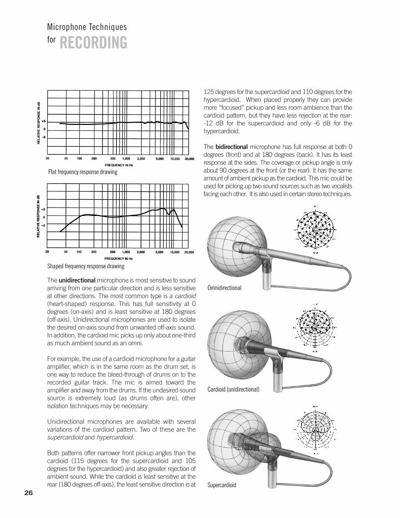
The unidirectional microphone is most sensitive to soundarriving from one particular direction and is less sensitiveat other directions. The most common type is a cardioid(heart-shaped) response. This has full sensitivity at 0 degrees (on-axis) and is least sensitive at 180 degrees (off-axis). Unidirectional microphones are used to isolatethe desired on-axis sound from unwanted off-axis sound.In addition, the cardioid mic picks up only about one-thirdas much ambient sound as an omni.
For example, the use of a cardioid microphone for a guitaramplifier, which is in the same room as the drum set, isone way to reduce the bleed-through of drums on to therecorded guitar track. The mic is aimed toward the amplifier and away from the drums. If the undesired soundsource is extremely loud (as drums often are), other isolation techniques may be necessary.
Unidirectional microphones are available with several variations of the cardioid pattern. Two of these are the supercardioid and hypercardioid.
Both patterns offer narrower front pickup angles than thecardioid (115 degrees for the supercardioid and 105 degrees for the hypercardioid) and also greater rejection ofambient sound. While the cardioid is least sensitive at therear (180 degrees off-axis), the least sensitive direction is at
125 degrees for the supercardioid and 110 degrees for thehypercardioid. When placed properly they can providemore “focused” pickup and less room ambience than thecardioid pattern, but they have less rejection at the rear: -12 dB for the supercardioid and only -6 dB for the hypercardioid.
The bidirectional microphone has full response at both 0 degrees (front) and at 180 degrees (back). It has its least response at the sides. The coverage or pickup angle is onlyabout 90 degrees at the front (or the rear). It has the sameamount of ambient pickup as the cardioid. This mic could beused for picking up two sound sources such as two vocalistsfacing each other. It is also used in certain stereo techniques.
26
RECORDINGMicrophone Techniquesfor
Flat frequency response drawing
Shaped frequency response drawing
Cardioid (unidirectional)
Omnidirectional
Supercardioid
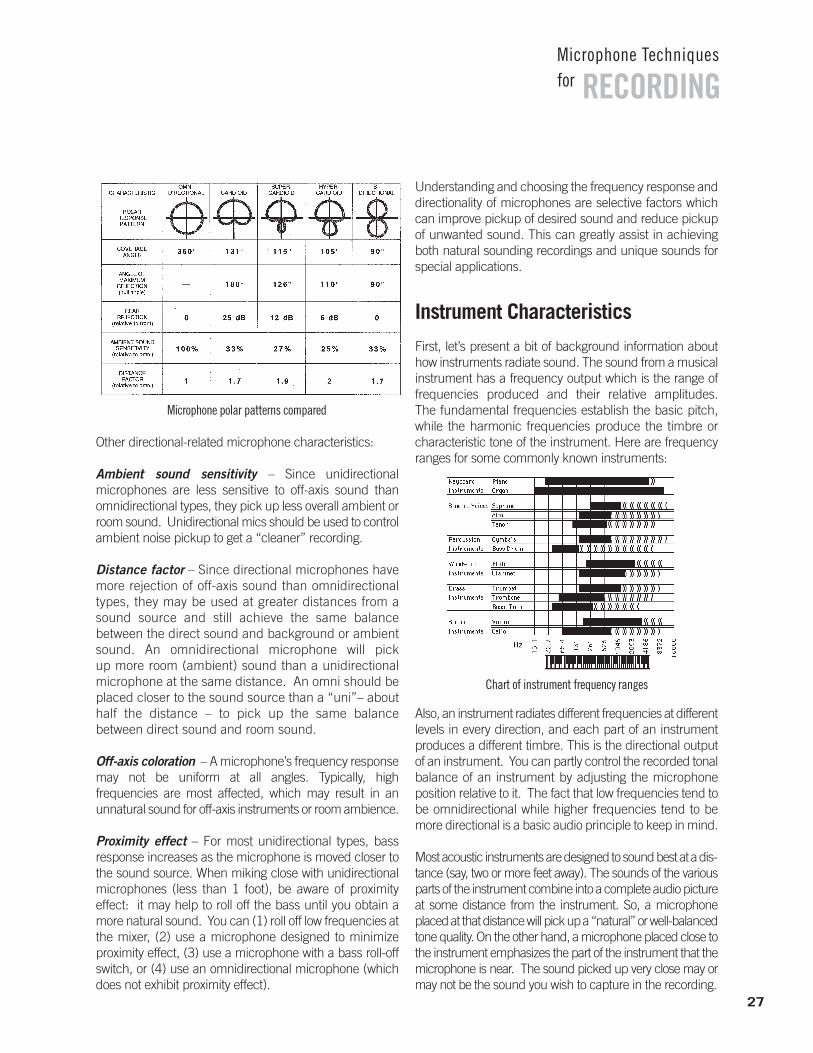
Other directional-related microphone characteristics:
Ambient sound sensitivity – Since unidirectional microphones are less sensitive to off-axis sound than omnidirectional types, they pick up less overall ambient orroom sound. Unidirectional mics should be used to controlambient noise pickup to get a “cleaner” recording.
Distance factor – Since directional microphones havemore rejection of off-axis sound than omnidirectionaltypes, they may be used at greater distances from asound source and still achieve the same balance between the direct sound and background or ambientsound. An omnidirectional microphone will pick up more room (ambient) sound than a unidirectionalmicrophone at the same distance. An omni should beplaced closer to the sound source than a “uni”– abouthalf the distance – to pick up the same balance between direct sound and room sound.
Off-axis coloration – A microphone’s frequency responsemay not be uniform at all angles. Typically, high frequencies are most affected, which may result in an unnatural sound for off-axis instruments or room ambience.
Proximity effect – For most unidirectional types, bass response increases as the microphone is moved closer tothe sound source. When miking close with unidirectionalmicrophones (less than 1 foot), be aware of proximity effect: it may help to roll off the bass until you obtain amore natural sound. You can (1) roll off low frequencies atthe mixer, (2) use a microphone designed to minimizeproximity effect, (3) use a microphone with a bass roll-offswitch, or (4) use an omnidirectional microphone (whichdoes not exhibit proximity effect).
Understanding and choosing the frequency response anddirectionality of microphones are selective factors whichcan improve pickup of desired sound and reduce pickupof unwanted sound. This can greatly assist in achievingboth natural sounding recordings and unique sounds forspecial applications.
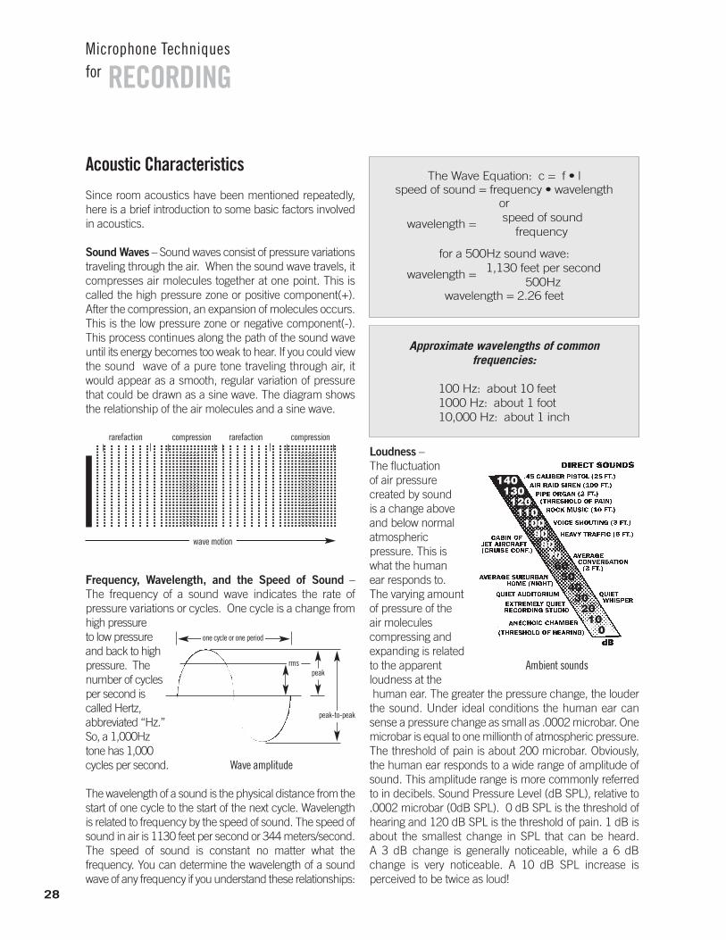
Instrument Characteristics
First, let’s present a bit of background information abouthow instruments radiate sound. The sound from a musicalinstrument has a frequency output which is the range offrequencies produced and their relative amplitudes. The fundamental frequencies establish the basic pitch,while the harmonic frequencies produce the timbre orcharacteristic tone of the instrument. Here are frequencyranges for some commonly known instruments:
Also, an instrument radiates different frequencies at differentlevels in every direction, and each part of an instrumentproduces a different timbre. This is the directional outputof an instrument. You can partly control the recorded tonal balance of an instrument by adjusting the microphone position relative to it. The fact that low frequencies tend tobe omnidirectional while higher frequencies tend to bemore directional is a basic audio principle to keep in mind.
Most acoustic instruments are designed to sound best at a dis-tance (say, two or more feet away). The sounds of the variousparts of the instrument combine into a complete audio pictureat some distance from the instrument. So, a microphoneplaced at that distance will pick up a “natural” or well-balancedtone quality. On the other hand, a microphone placed close tothe instrument emphasizes the part of the instrument that themicrophone is near. The sound picked up very close may ormay not be the sound you wish to capture in the recording.
27
RECORDINGMicrophone Techniquesfor
Microphone polar patterns compared
Chart of instrument frequency ranges
Acoustic CharacteristicsSince room acoustics have been mentioned repeatedly,here is a brief introduction to some basic factors involvedin acoustics.
Sound Waves – Sound waves consist of pressure variationstraveling through the air. When the sound wave travels, itcompresses air molecules together at one point. This iscalled the high pressure zone or positive component(+).After the compression, an expansion of molecules occurs.This is the low pressure zone or negative component(-).This process continues along the path of the sound waveuntil its energy becomes too weak to hear. If you could viewthe sound wave of a pure tone traveling through air, itwould appear as a smooth, regular variation of pressurethat could be drawn as a sine wave. The diagram showsthe relationship of the air molecules and a sine wave.
Frequency, Wavelength, and the Speed of Sound –The frequency of a sound wave indicates the rate of pressure variations or cycles. One cycle is a change from high pressure to low pressure and back to highpressure. Thenumber of cyclesper second is called Hertz, abbreviated “Hz.”So, a 1,000Hztone has 1,000cycles per second.
The wavelength of a sound is the physical distance from thestart of one cycle to the start of the next cycle. Wavelengthis related to frequency by the speed of sound. The speed ofsound in air is 1130 feet per second or 344 meters/second.The speed of sound is constant no matter what the frequency. You can determine the wavelength of a soundwave of any frequency if you understand these relationships:
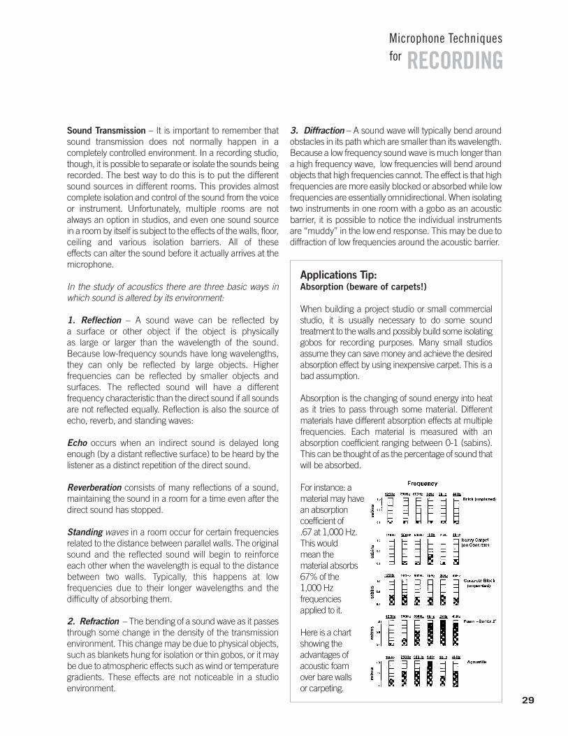
Loudness –The fluctuation of air pressure created by sound is a change above and below normal atmospheric pressure. This is what the human ear responds to. The varying amountof pressure of the air molecules compressing and expanding is relatedto the apparent loudness at thehuman ear. The greater the pressure change, the louderthe sound. Under ideal conditions the human ear cansense a pressure change as small as .0002 microbar. Onemicrobar is equal to one millionth of atmospheric pressure.The threshold of pain is about 200 microbar. Obviously,the human ear responds to a wide range of amplitude ofsound. This amplitude range is more commonly referredto in decibels. Sound Pressure Level (dB SPL), relative to.0002 microbar (0dB SPL). 0 dB SPL is the threshold ofhearing and 120 dB SPL is the threshold of pain. 1 dB isabout the smallest change in SPL that can be heard. A 3 dB change is generally noticeable, while a 6 dBchange is very noticeable. A 10 dB SPL increase is perceived to be twice as loud!
28
RECORDINGMicrophone Techniquesfor
Ambient sounds
1401301201101009080706050403020100
......
......
......
......
....
......
......
......
......
....
......
......
......
......
....
......
......
......
......
....
......
......
......
......
....
......
......
......
......
....
......
......
......
......
....
......
......
......
......
....
......
......
......
......
....
......
......
......
......
....
......
......
......
......
....
......
......
......
......
....
......
......
......
......
....
......
......
......
......
....
......
......
......
......
....
......
......
......
......
....
......
......
......
......
....
......
......
......
......
....
......
......
......
......
....
......
......
......
......
....
......
......
......
......
....
......
......
......
......
....
......
......
......
......
....
......
......
......
......
....
......
......
......
......
....
......
......
......
......
....
......
......
......
......
....
......
......
......
......
....
......
......
......
......
....
......
......
......
......
....
......
......
......
......
....
......
......
......
......
....
......
......
......
......
....
......
......
......
......
....
......
......
......
......
....
......
......
......
......
....
......
......
......
......
....
......
......
......
......
....
......
......
......
......
....
......
......
......
......
....
......
......
......
......
....
......
......
......
......
....
......
......
......
......
....
......
......
......
......
....
......
......
......
......
....
......
......
......
......
....
......
......
......
......
....
......
......
......
......
....
......
......
......
......
....
....
....
....
....
....
....
...
....
....
....
....
....
....
...
....
....
....
....
....
....
...
....
....
....
....
....
....
...
....
....
....
....
....
....
...
....
....
....
....
....
....
...
....
....
....
....
....
....
...
....
....
....
....
....
....
...
....
....
....
....
....
....
...
....
....
....
....
....
....
...
rarefaction rarefactioncompression compression
wave motion
Approximate wavelengths of common frequencies:
100 Hz: about 10 feet1000 Hz: about 1 foot10,000 Hz: about 1 inch
The Wave Equation: c = f • lspeed of sound = frequency • wavelength
or
wavelength = speed of sound frequency
for a 500Hz sound wave:
wavelength = 1,130 feet per second 500Hz
wavelength = 2.26 feet
Wave amplitude
peak-to-peak
peakrms
one cycle or one period
Sound Transmission – It is important to remember thatsound transmission does not normally happen in a completely controlled environment. In a recording studio,though, it is possible to separate or isolate the sounds beingrecorded. The best way to do this is to put the differentsound sources in different rooms. This provides almostcomplete isolation and control of the sound from the voiceor instrument. Unfortunately, multiple rooms are not always an option in studios, and even one sound source in a room by itself is subject to the effects of the walls, floor,ceiling and various isolation barriers. All of these effects can alter the sound before it actually arrives at themicrophone.
In the study of acoustics there are three basic ways inwhich sound is altered by its environment:
1. Reflection – A sound wave can be reflected by a surface or other object if the object is physically as large or larger than the wavelength of the sound. Because low-frequency sounds have long wavelengths,they can only be reflected by large objects. Higher frequencies can be reflected by smaller objects and surfaces. The reflected sound will have a different frequency characteristic than the direct sound if all soundsare not reflected equally. Reflection is also the source ofecho, reverb, and standing waves:
Echo occurs when an indirect sound is delayed longenough (by a distant reflective surface) to be heard by thelistener as a distinct repetition of the direct sound.
Reverberation consists of many reflections of a sound,maintaining the sound in a room for a time even after thedirect sound has stopped.
Standing waves in a room occur for certain frequencies related to the distance between parallel walls. The originalsound and the reflected sound will begin to reinforceeach other when the wavelength is equal to the distancebetween two walls. Typically, this happens at low frequencies due to their longer wavelengths and the difficulty of absorbing them.
2. Refraction – The bending of a sound wave as it passesthrough some change in the density of the transmissionenvironment. This change may be due to physical objects,such as blankets hung for isolation or thin gobos, or it maybe due to atmospheric effects such as wind or temperaturegradients. These effects are not noticeable in a studio environment.
3. Diffraction – A sound wave will typically bend aroundobstacles in its path which are smaller than its wavelength.Because a low frequency sound wave is much longer thana high frequency wave, low frequencies will bend aroundobjects that high frequencies cannot. The effect is that highfrequencies are more easily blocked or absorbed while lowfrequencies are essentially omnidirectional. When isolatingtwo instruments in one room with a gobo as an acousticbarrier, it is possible to notice the individual instrumentsare “muddy” in the low end response. This may be due todiffraction of low frequencies around the acoustic barrier.
RECORDINGMicrophone Techniquesfor
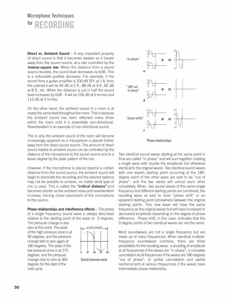
Applications Tip:Absorption (beware of carpets!)
When building a project studio or small commercial studio, it is usually necessary to do some sound treatment to the walls and possibly build some isolatinggobos for recording purposes. Many small studios assume they can save money and achieve the desiredabsorption effect by using inexpensive carpet. This is abad assumption.
Absorption is the changing of sound energy into heatas it tries to pass through some material. Different materials have different absorption effects at multiplefrequencies. Each material is measured with an absorption coefficient ranging between 0-1 (sabins).This can be thought of as the percentage of sound thatwill be absorbed.
For instance: amaterial may havean absorption coefficient of .67 at 1,000 Hz. This would mean the material absorbs67% of the 1,000 Hz frequenciesapplied to it.
Here is a chartshowing the advantages ofacoustic foam over bare walls or carpeting.
29
Direct vs. Ambient Sound – A very important propertyof direct sound is that it becomes weaker as it travelsaway from the sound source, at a rate controlled by the inverse-square law. When the distance from a soundsource doubles, the sound level decreases by 6dB. Thisis a noticeable audible decrease. For example, if thesound from a guitar amplifier is 100 dB SPL at 1 ft. fromthe cabinet it will be 94 dB at 2 ft., 88 dB at 4 ft., 82 dBat 8 ft., etc. When the distance is cut in half the soundlevel increases by 6dB: It will be 106 dB at 6 inches and112 dB at 3 inches.
On the other hand, the ambient sound in a room is atnearly the same level throughout the room. This is becausethe ambient sound has been reflected many times within the room until it is essentially non-directional. Reverberation is an example of non-directional sound.
This is why the ambient sound of the room will becomeincreasingly apparent as a microphone is placed furtheraway from the direct sound source. The amount of directsound relative to ambient sound can be controlled by thedistance of the microphone to the sound source and to alesser degree by the polar pattern of the mic.
However, if the microphone is placed beyond a certaindistance from the sound source, the ambient sound willbegin to dominate the recording and the desired balancemay not be possible to achieve, no matter what type ofmic is used. This is called the “critical distance” and becomes shorter as the ambient noise and reverberationincrease, forcing closer placement of the microphone to the source.
Phase relationships and interference effects – The phaseof a single frequency sound wave is always described relative to the starting point of the wave or 0 degrees. The pressure change is alsozero at this point. The peak of the high pressure zone is at90 degrees, and the pressurechange falls to zero again at180 degrees. The peak of thelow pressure zone is at 270 degrees, and the pressurechange rises to zero at 360 degrees for the start of the next cycle.
Two identical sound waves starting at the same point intime are called “in-phase” and will sum together creatinga single wave with double the amplitude but otherwiseidentical to the original waves. Two identical sound waveswith one wave’s starting point occurring at the 180-degree point of the other wave are said to be “out ofphase”, and the two waves will cancel each other completely. When two sound waves of the same singlefrequency but different starting points are combined, theresulting wave as said to have “phase shift” or an apparent starting point somewhere between the originalstarting points. This new wave will have the same frequency as the original waves but will have increased ordecreased amplitude depending on the degree of phasedifference. Phase shift, in this case, indicates that the 0 degree points of two identical waves are not the same.
Most soundwaves are not a single frequency but are made up of many frequencies. When identical multiple-frequency soundwaves combine, there are three possibilities for the resulting wave: a doubling of amplitudeat all frequencies if the waves are “in phase”, a completecancellation at all frequencies if the waves are 180 degrees “out of phase”, or partial cancellation and partial reinforcement at various frequencies if the waves have intermediate phase relationship.
30
RECORDINGMicrophone Techniquesfor
Sound pressure wave
▲
▲one cycle or one period
90000 1800 2700 3600
Phase relationships
+
+1
0
-1
+1
0
-1a
=
+2
0
-2
+
+1
0
-1
+1
0
-1b
= 0
+
+1
0
-1
+1
0
-1c
=“phase shifts”
“in-phase”
”1800 out of phase”
+2
+1
0
-1
-2
The last case is the most likely, and the audible result is adegraded frequency response called “comb filtering.” Thepattern of peaks and dips resembles the teeth of a comband the depth and location of these notches depend onthe degree of phase shift.
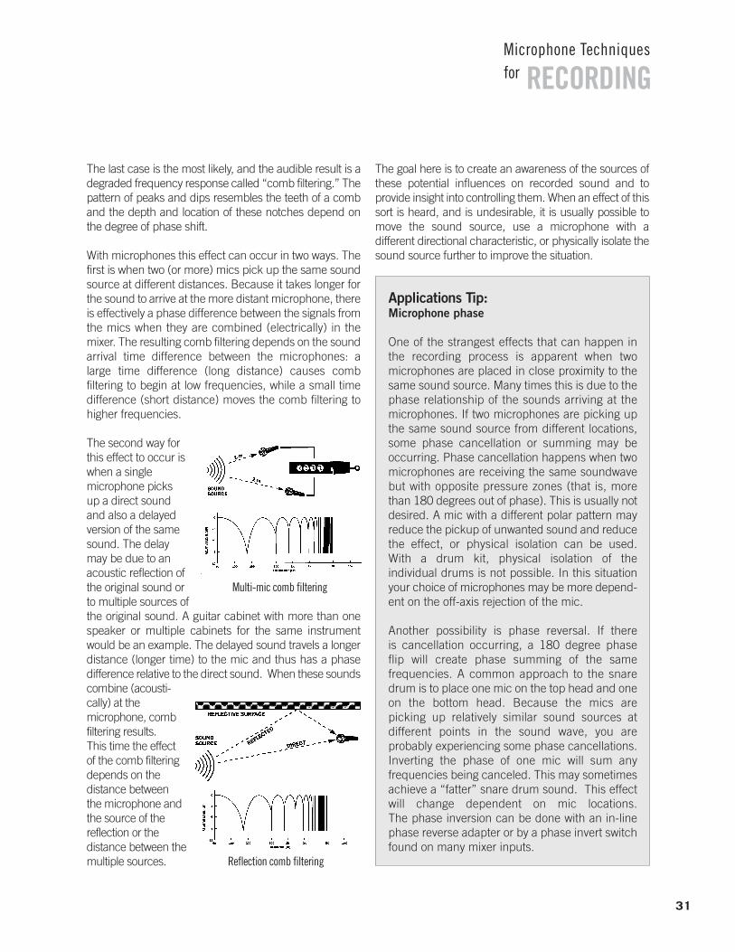
With microphones this effect can occur in two ways. Thefirst is when two (or more) mics pick up the same soundsource at different distances. Because it takes longer forthe sound to arrive at the more distant microphone, thereis effectively a phase difference between the signals fromthe mics when they are combined (electrically) in themixer. The resulting comb filtering depends on the soundarrival time difference between the microphones: a large time difference (long distance) causes comb filtering to begin at low frequencies, while a small timedifference (short distance) moves the comb filtering tohigher frequencies.
The second way forthis effect to occur iswhen a single microphone picks up a direct soundand also a delayed version of the samesound. The delaymay be due to anacoustic reflection ofthe original sound orto multiple sources ofthe original sound. A guitar cabinet with more than onespeaker or multiple cabinets for the same instrumentwould be an example. The delayed sound travels a longerdistance (longer time) to the mic and thus has a phasedifference relative to the direct sound. When these sounds combine (acousti-cally) at the microphone, combfiltering results. This time the effect of the comb filteringdepends on the distance between the microphone andthe source of the reflection or the distance between themultiple sources.
The goal here is to create an awareness of the sources ofthese potential influences on recorded sound and to provide insight into controlling them. When an effect of thissort is heard, and is undesirable, it is usually possible tomove the sound source, use a microphone with adifferent directional characteristic, or physically isolate thesound source further to improve the situation.
31
RECORDINGMicrophone Techniquesfor
Multi-mic comb filtering
Reflection comb filtering
Applications Tip:Microphone phase
One of the strangest effects that can happen in the recording process is apparent when two microphones are placed in close proximity to thesame sound source. Many times this is due to thephase relationship of the sounds arriving at the microphones. If two microphones are picking upthe same sound source from different locations,some phase cancellation or summing may be occurring. Phase cancellation happens when twomicrophones are receiving the same soundwavebut with opposite pressure zones (that is, morethan 180 degrees out of phase). This is usually notdesired. A mic with a different polar pattern mayreduce the pickup of unwanted sound and reducethe effect, or physical isolation can be used. With a drum kit, physical isolation of the individual drums is not possible. In this situationyour choice of microphones may be more depend-ent on the off-axis rejection of the mic.
Another possibility is phase reversal. If there is cancellation occurring, a 180 degree phase flip will create phase summing of the same frequencies. A common approach to the snaredrum is to place one mic on the top head and oneon the bottom head. Because the mics are picking up relatively similar sound sources at different points in the sound wave, you are probably experiencing some phase cancellations.Inverting the phase of one mic will sum any frequencies being canceled. This may sometimesachieve a “fatter” snare drum sound. This effectwill change dependent on mic locations. The phase inversion can be done with an in-linephase reverse adapter or by a phase invert switchfound on many mixer inputs.
32
RECORDINGMicrophone Techniquesfor
Solo VocalKSM44KSM27SM7BSM58
Ensemble/ChoirKSM32KSM141KSM137KSM109
Podcasting/Voice-Over
KSM27SM7BSM5855SH Series II
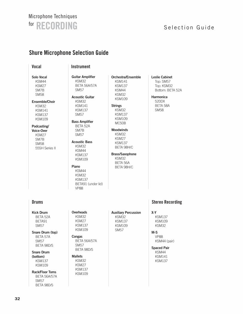
Shure Microphone Selection Guide
Vocal Instrument
Orchestra/EnsembleKSM141KSM137KSM44KSM32KSM109
StringsKSM32KSM137KSM109MC50B
WoodwindsKSM32KSM27KSM137BETA 98H/C
Brass/SaxophoneKSM32BETA 56ABETA 98H/C
Leslie CabinetTop: SM57Top: KSM32Bottom: BETA 52A
Harmonica520DXBETA 58ASM58
Guitar AmplifierKSM32BETA 56A/57ASM57
Acoustic Guitar KSM32KSM141KSM137SM57
Bass AmplifierBETA 52ASM7BSM57
Acoustic BassKSM32KSM44KSM137KSM109
PianoKSM44KSM32KSM137BETA91 (under lid)VP88
Kick DrumBETA 52ABETA91SM57
Snare Drum (top)BETA 57ASM57BETA 98D/S
Snare Drum (bottom)
KSM137KSM109
Rack/Floor TomsBETA 56A/57ASM57BETA 98D/S
Drums Stereo Recording
Auxiliary PercussionKSM32KSM137KSM109SM57
X-YKSM137KSM109KSM32
M-SVP88KSM44 (pair)
Spaced PairKSM44KSM141KSM137
OverheadsKSM32KSM27KSM137KSM109
CongasBETA 56A/57ASM57BETA 98D/S
MalletsKSM32KSM27KSM137KSM109
Se l e c t i o n Gu i d e
RECORDINGMicrophone Techniquesfor
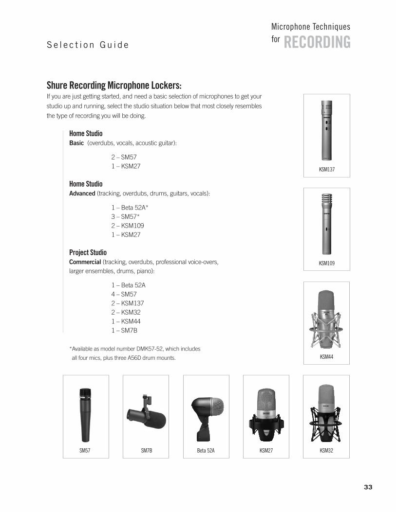
Shure Recording Microphone Lockers: If you are just getting started, and need a basic selection of microphones to get your
studio up and running, select the studio situation below that most closely resembles
the type of recording you will be doing.
Se l e c t i o n Gu i d e
Home Studio Basic (overdubs, vocals, acoustic guitar):
2 – SM571 – KSM27
Home StudioAdvanced (tracking, overdubs, drums, guitars, vocals):
1 – Beta 52A*3 – SM57*2 – KSM1091 – KSM27
Project StudioCommercial (tracking, overdubs, professional voice-overs, larger ensembles, drums, piano):
1 – Beta 52A4 – SM572 – KSM1372 – KSM321 – KSM441 – SM7B
*Available as model number DMK57-52, which includes
all four mics, plus three A56D drum mounts.
KSM32SM57 SM7B Beta 52A
KSM44
KSM109
KSM137
KSM27
33
3-to-1 Rule - When using multiple microphones, the distancebetween microphones should be at least 3 times the distancefrom each microphone to its intended sound source.
Absorption - The dissipation of sound energy by losses due tosound absorbent materials.
Active Circuitry - Electrical circuitry which requires power to operate, such as transistors and vacuum tubes.
Ambience - Room acoustics or natural reverberation.
Amplitude - The strength or level of sound pressure or voltage.
Audio Chain - The series of interconnected audio equipmentused for recording or PA.
Backplate - The solid conductive disk that forms the fixed halfof a condenser element.
Balanced - A circuit that carries information by means of twoequal but opposite polarity signals, on two conductors.
Bidirectional Microphone - A microphone that picks upequally from two opposite directions. The angle of best rejection is 90 degrees from the front (or rear) of the microphone, that is, directly at the sides.
Boundary/Surface Microphone - A microphone designed to be mounted on an acoustically reflective surface.
Cardioid Microphone - A unidirectional microphone with moderately wide front pickup (131 degrees). Angle of best rejection is 180 degrees from the front of the microphone, that is, directly at the rear.
Cartridge (Transducer) - The element in a microphone thatconverts acoustical energy (sound) into electrical energy (the signal).
Clipping Level - The maximum electrical output signal level(dBV or dBu) that the microphone can produce before the output becomes distorted.
Close Pickup - Microphone placement within 2 feet of a soundsource.
Comb Filtering - An interference effect in which the frequencyresponse exhibits regular deep notches.
Condenser Microphone - A microphone that generates an electrical signal when sound waves vary the spacing betweentwo charged surfaces: the diaphragm and the backplate.
Critical Distance - In acoustics, the distance from a soundsource in a room at which the direct sound level is equal to the reverberant sound level.
Current - Charge flowing in an electrical circuit. Analogous tothe amount of a fluid flowing in a pipe.
Decibel (dB) - A number used to express relative output sensitivity. It is a logarithmic ratio.
Diaphragm - The thin membrane in a microphone whichmoves in response to sound waves.
Diffraction - The bending of sound waves around an objectwhich is physically smaller than the wavelength of the sound.
Direct Sound - Sound which travels by a straight path from asound source to a microphone or listener.
Distance Factor - The equivalent operating distance of a directional microphone compared to an omnidirectional micro-phone to achieve the same ratio of direct to reverberant sound.
Distant Pickup - Microphone placement farther than 2 feetfrom the sound source.
Dynamic Microphone - A microphone that generates an electrical signal when sound waves cause a conductor to vibrate in a magnetic field. In a moving-coil microphone, the conductor is a coil of wire attached to the diaphragm. In a ribbon microphone, the diaphragm is the conductor.
Dynamic Range - The range of amplitude of a sound source.Also, the range of sound level that a microphone can successfully pick up.
Echo - Reflection of sound that is delayed long enough (more than about 50 msec.) to be heard as a distinct repetitionof the original sound.
Electret - A material (such as Teflon) that can retain a permanent electric charge.
EQ - Equalization or tone control to shape frequency responsein some desired way.
Feedback - In a PA system consisting of a microphone, amplifier, and loudspeaker, feedback is the ringing or howlingsound caused by amplified sound from the loudspeaker entering the microphone and being re-amplified.
Flat Response - A frequency response that is uniform andequal at all frequencies.
Frequency - The rate of repetition of a cyclic phenomenonsuch as a sound wave.
Frequency Response Tailoring Switch - A switch on a microphone that affects the tone quality reproduced by the microphone by means of an equalization circuit. (Similar to a bass or treble control on a hi-fi receiver.)
34
RECORDINGMicrophone Techniquesfor
G l o s s a r y
Frequency Response - A graph showing how a microphone responds to various sound frequencies. It is a plot of electricaloutput (in decibels) vs. frequency (in Hertz).
Fundamental - The lowest frequency component of a complexwaveform such as musical note. It establishes the basic pitch of the note.
Gain - Amplification of sound level or voltage.
Gain-Before-Feedback - The amount of gain that can beachieved in a sound system before feedback or ringing occurs.
Gobos - Movable panels used to reduce reflected sound in the recording environment.
Harmonic - Frequency components above the fundamental of a complex waveform. They are generally multiples of the fundamental which establish the timbre or tone of the note.
Hypercardioid - A unidirectional microphone with tighter frontpickup (105 degrees) than a supercardioid, but with more rearpickup. Angle of best rejection is about 110 degrees from thefront of the microphone.
Impedance - In an electrical circuit, opposition to the flow ofalternating current, measured in ohms. A high-impedance microphone has an impedance of 10,000 ohms or more. A low-impedance microphone has an impedance of 50 to 600 ohms.
Interference - Destructive combining of sound waves or electrical signals due to phase differences.
Inverse Square Law - States that direct sound levels increase(or decrease) by an amount proportional to the square of thechange in distance.
Isolation - Freedom from leakage; the ability to reject unwanted sounds.
Leakage - Pickup of an instrument by a microphone intendedto pick up another instrument. Creative leakage is artistically favorable leakage that adds a “loose” or “live” feel to a recording.
Maximum Sound Pressure Level - The maximum acousticinput signal level (dB SPL) that the microphone can accept before clipping occurs.
Microphone Sensitivity - A rating given in dBV to express how“hot” the microphone is by exposing the microphone to a specified sound field level (typically either 94 dB SPL or 74 dBSPL). This specification can be confusing because manufacturers designate the sound level different ways. Here is an easy reference guide: 94 dB SPL = 1 Pascal = 10microbars. To compare a microphone that has been measuredat 74 dB SPL with one that has been measured at 94 dB SPL,simply add 20 to the dBV rating.
NAG - Needed Acoustic Gain is the amount of gain that asound system must provide for a distant listener to hear as if he or she was close to the unamplified sound source.
Noise - Unwanted electrical or acoustic interference.
Noise Cancelling - A microphone that rejects ambient or distant sound.
NOM - Number of open microphones in a sound system. Decreases gain-before-feedback by 3dB everytime NOM doubles.
Omnidirectional Microphone - A microphone that picks upsound equally well from all directions.
Output Noise (Self-Noise) - The amount of residual noise (dBSPL) generated by the electronics of a condenser microphone.
Overload - Exceeding the signal level capability of a microphone or electrical circuit.
PAG - Potential Acoustic Gain is the calculated gain that a soundsystem can achieve at or just below the point of feedback.
Phantom Power - A method of providing power to the electronics of a condenser microphone through the microphone cable.
Phase - The “time” relationship between cycles of different waves.
Pickup Angle/Coverage Angle - The effective arc of coverage ofa microphone, usually taken to be within the 3dB down pointsin its directional response.
Pitch - The fundamental or basic frequency of a musical note.
Polar Pattern (Directional Pattern, Polar Response) - A graphshowing how the sensitivity of a microphone varies with theangle of the sound source, at a particular frequency. Examplesof polar patterns are unidirectional and omnidirectional.
Polarization - The charge or voltage on a condenser microphone element.
Pop Filter - An acoustically transparent shield around a microphone cartridge that reduces popping sounds. Often a ball-shaped grille, foam cover or fabric barrier.
Pop - A thump of explosive breath sound produced when apuff of air from the mouth strikes the microphone diaphragm.Occurs most often with “p”, “t”, and “b” sounds.
Presence Peak - An increase in microphone output in the“presence” frequency range of 2,000 Hz to 10,000 Hz. A presence peak increases clarity, articulation, apparent closeness, and “punch.”
35
RECORDINGMicrophone Techniquesfor
G l o s s a r y
Proximity Effect - The increase in bass occurring with most unidirectional microphones when they are placed close to aninstrument or vocalist (within 1 foot). Does not occur with omnidirectional microphones.
Rear Lobe - A region of pickup at the rear of a supercardioid or hypercardioid microphone polar pattern. A bidirectional microphone has a rear lobe equal to its front pickup.
Reflection - The bouncing of sound waves back from an object or surface which is physically larger than the wavelength of the sound.
Refraction - The bending of sound waves by a change in the density of the transmission medium, such as temperaturegradients in air due to wind.
Resistance - The opposition to the flow of current in an electricalcircuit. It is analogous to the friction of fluid flowing in a pipe.
Reverberation - The reflection of a sound a sufficient number of times that it becomes non-directional and persists for sometime after the source has stopped. The amount of reverberationdepends on the relative amount of sound reflection and absorption in the room.
Rolloff - A gradual decrease in response below or above somespecified frequency.
Sensitivity - The electrical output that a microphone producesfor a given sound pressure level.
Shaped Response - A frequency response that exhibits significant variation from flat within its range. It is usually designed to enhance the sound for a particular application.
Signal to Noise Ratio - The amount of signal (dBV) above thenoise floor when a specified sound pressure level is applied tothe microphone (usually 94 dB SPL).
Sound Chain - The series of interconnected audio equipmentused for recording or PA.
Sound Reinforcement - Amplification of live sound sources.
Speed of Sound - The speed of sound waves, about 1130 feetper second in air.
SPL - Sound Pressure Level is the loudness of sound relative toa reference level of 0.0002 microbars.
Standing Wave - A stationary sound wave that is reinforced byreflection between two parallel surfaces that are spaced awavelength apart.
Supercardioid Microphone - A unidirectional microphone withtighter front pickup angle (115 degrees) than a cardioid, but withsome rear pickup. Angle of best rejection is 126 degrees fromthe front of the microphone, that is, 54 degrees from the rear.
3-to-1 Rule - (See top of page 34.)
Timbre - The characteristic tone of a voice or instrument; a function of harmonics.
Transducer - A device that converts one form of energy to another. A microphone transducer (cartridge) converts acoustical energy (sound) into electrical energy (the audio signal).
Transient Response - The ability of a device to respond to arapidly changing input.
Unbalanced - A circuit that carries information by means ofone signal on a single conductor.
Unidirectional Microphone - A microphone that is most sensitive to sound coming from a single direction-in front of the microphone. Cardioid, supercardioid, and hypercardioidmicrophones are examples of unidirectional microphones.
Vacuum Tube (valve) - An electric device generally used to amplify a signal by controlling the movement of electrons in avacuum. Vacuum tubes were widely used in the early part ofthe 20th century, but have largely been replaced by transistors.
Voice Coil - Small coil of wire attached to the diaphragm of adynamic microphone.
Voltage - The potential difference in an electric circuit. Analogous to the pressure on fluid flowing in a pipe.
Wavelength - The physical distance between the start and endof one cycle of a soundwave.
36
RECORDINGMicrophone Techniquesfor
G l o s s a r y
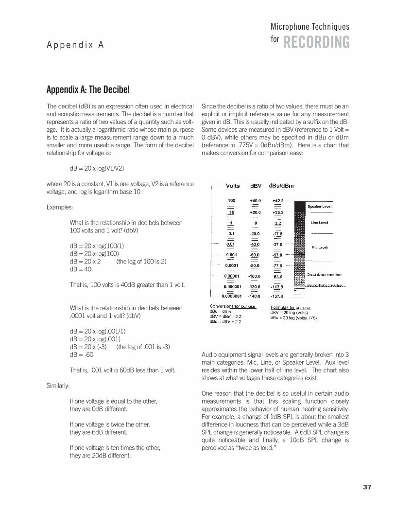
Appendix A: The DecibelThe decibel (dB) is an expression often used in electricaland acoustic measurements. The decibel is a number thatrepresents a ratio of two values of a quantity such as volt-age. It is actually a logarithmic ratio whose main purposeis to scale a large measurement range down to a muchsmaller and more useable range. The form of the decibelrelationship for voltage is:
dB = 20 x log(V1/V2)
where 20 is a constant, V1 is one voltage, V2 is a referencevoltage, and log is logarithm base 10.
Examples:
What is the relationship in decibels between100 volts and 1 volt? (dbV)
dB = 20 x log(100/1)dB = 20 x log(100)dB = 20 x 2 (the log of 100 is 2)dB = 40
That is, 100 volts is 40dB greater than 1 volt.
What is the relationship in decibels between.0001 volt and 1 volt? (dbV)
dB = 20 x log(.001/1)dB = 20 x log(.001)dB = 20 x (-3) (the log of .001 is -3)dB = -60
That is, .001 volt is 60dB less than 1 volt.
Similarly:
If one voltage is equal to the other, they are 0dB different.
If one voltage is twice the other, they are 6dB different.
If one voltage is ten times the other, they are 20dB different.
Since the decibel is a ratio of two values, there must be anexplicit or implicit reference value for any measurementgiven in dB. This is usually indicated by a suffix on the dB.Some devices are measured in dBV (reference to 1 Volt =0 dBV), while others may be specified in dBu or dBm (reference to .775V = 0dBu/dBm). Here is a chart thatmakes conversion for comparison easy:
Audio equipment signal levels are generally broken into 3main categories: Mic, Line, or Speaker Level. Aux level resides within the lower half of line level. The chart alsoshows at what voltages these categories exist.
One reason that the decibel is so useful in certain audiomeasurements is that this scaling function closely approximates the behavior of human hearing sensitivity.For example, a change of 1dB SPL is about the smallestdifference in loudness that can be perceived while a 3dBSPL change is generally noticeable. A 6dB SPL change isquite noticeable and finally, a 10dB SPL change is perceived as “twice as loud.”
37
RECORDINGMicrophone Techniquesfor
Append i x A
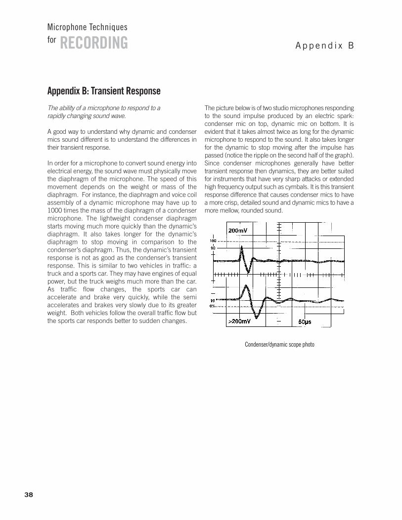
Appendix B: Transient ResponseThe ability of a microphone to respond to a rapidly changing sound wave.
A good way to understand why dynamic and condensermics sound different is to understand the differences intheir transient response.
In order for a microphone to convert sound energy intoelectrical energy, the sound wave must physically movethe diaphragm of the microphone. The speed of thismovement depends on the weight or mass of the diaphragm. For instance, the diaphragm and voice coilassembly of a dynamic microphone may have up to1000 times the mass of the diaphragm of a condensermicrophone. The lightweight condenser diaphragmstarts moving much more quickly than the dynamic’sdiaphragm. It also takes longer for the dynamic’s diaphragm to stop moving in comparison to the condenser’s diaphragm. Thus, the dynamic’s transientresponse is not as good as the condenser’s transientresponse. This is similar to two vehicles in traffic: atruck and a sports car. They may have engines of equalpower, but the truck weighs much more than the car.As traffic flow changes, the sports car can accelerate and brake very quickly, while the semi accelerates and brakes very slowly due to its greaterweight. Both vehicles follow the overall traffic flow butthe sports car responds better to sudden changes.
The picture below is of two studio microphones respondingto the sound impulse produced by an electric spark: condenser mic on top, dynamic mic on bottom. It is evident that it takes almost twice as long for the dynamicmicrophone to respond to the sound. It also takes longerfor the dynamic to stop moving after the impulse haspassed (notice the ripple on the second half of the graph).Since condenser microphones generally have better transient response then dynamics, they are better suitedfor instruments that have very sharp attacks or extendedhigh frequency output such as cymbals. It is this transientresponse difference that causes condenser mics to havea more crisp, detailed sound and dynamic mics to have amore mellow, rounded sound.
38
RECORDINGMicrophone Techniquesfor
Append i x B
Condenser/dynamic scope photo
RECORDINGMicrophone Techniquesfor
John Boudreau John has had extensive experience as a musician,
a recording engineer, and a composer. His desire to better combine the artistic and technical aspects of music led him to acareer in the audio field.
Having received a BS degree in Music Business fromElmhurst College, John performed and composed for both a Jazzand a Rock band prior to joining Shure in 1994 as an associatein the Applications Engineering group. While at Shure, John ledmany audio product training seminars and clinics, with an eye to helping musicians and others affiliated with the field use technology to better fulfill their artistic interpretations.
No longer a Shure associate, John continues to pursue hisinterests as a live and recorded sound engineer for local bandsand venues, as well as writing and recording for his own band.
Rick Frank Over his career, Rick has been involved in a wide variety of
music and recording activities including composing, teaching,performing, and producing popular music, jazz and commercialjingles. He has spent his life in Illinois where he received his BSin English and his MBA from the University of Illinois, Urbana-Champaign. While in downstate Illinois he also operateda successful retail musical instrument business and teaching program that coincided with working as a professional guitaristand electric bassist.
Rick was Shure’s Marketing Director for Wired Microphones,responsible for Music Industry products. No longer a Shure associate, he continues to perform music professionally.
Gino SigismondiGino, a Chicago native and Shure Applications Specialist
since 1997, has been active in the music and audio industry fornearly ten years. In addition to his work as a live sound andrecording engineer, Gino’s experience also includes performingand composing. Gino earned his BS degree in Music Businessfrom Elmhurst College, where he was a member of the JazzBand, as both guitar player and sound technician. As a memberof Applications Engineering, Gino brings his years of practical experience to the product training seminars he conducts forShure customers, dealers, distribution centers, and internal staff.Gino continues to remain active as a sound engineer, expandinghis horizons beyond live music to include sound design for modern dance and church sound.
Tim Vear Tim is a native of Chicago who has come to the audio field
as a way of combining a lifelong interest in both entertainmentand science. He has worked as an engineer in live sound,recording and broadcast, has operated his own recording studioand sound company, and has played music professionally sincehigh school.
In his tenure at Shure, Tim has served in a technical supportrole for the sales and marketing departments, providing productand applications training for Shure customers, dealers, installers,and company staff. He has presented seminars for a variety of domestic and international audiences, including the National Systems contractors Association, the Audio Engineering Societyand the Society of Broadcast Engineers. Tim has authored several publications for Shure and his articles have appeared inseveral trade publications.
Rick Waller An interest in the technical and musical aspects of audio
has led Rick to pursue a career as both engineer and musician.He received a BS degree in Electrical Engineering from the University of Illinois at Urbana/Champaign, where he specializedin acoustics, audio synthesis and radio frequency theory. Rick isan avid keyboardist, drummer and home theater hobbyist andhas also worked as a sound engineer and disc jockey. Currentlyhe is an associate in the Applications Engineering Group at Shure.In this capacity Rick provides technical support to customers,writing and conducting seminars on wired and wireless microphones, mixers and other audio topics.
Abou t t h e Au t h o r s
www.shure.com
United States:Shure Incorporated5800 West Touhy AvenueNiles, IL 60714-4608 USA
Phone: 847-600-2000Fax: 847-600-1212Email: [email protected]
Europe, Middle East, Africa:Shure Europe GmbHWannenäckerstr. 28,74078 Heilbronn, Germany
Phone: 49-7131-72140Fax: 49-7131-721414Email: [email protected]
Asia, Pacifi c:Shure Asia Limited3/F, Citicorp Centre18 Whitfi eld RoadCauseway Bay, Hong Kong
Phone: 852-2893-4290Fax: 852-2893-4055Email: [email protected]
Canada, Latin America,Caribbean:Shure Incorporated5800 West Touhy AvenueNiles, IL 60714-4608 USA
Phone: 847-600-2000Fax: 847-600-6446Email: [email protected]
©2007 Shure Incorporated AL0000
Additional Shure Publications Available:
Printed and electronic versions of the following guides are available free of charge.
To obtain your complimentary copies, call one of the phone numbers listed below or
visit www.shure.com/literature.
• Selection and Operation of Personal Monitor Systems
• Selection and Operation of Wireless Microphone Systems
• Microphone Techniques for Live Sound Reinforcement
Other Sources of Information:
There are books written about acoustics and how to mathematically determine their effects.
Here are a few:
• FUNDAMENTALS OF MUSICAL ACOUSTICS by Arthur H. Benade
• ACOUSTICS SOURCE BOOK by Sybil P. Parker
• MODERN RECORDING TECHNIQUES by Huber & Runstein
• THE MASTER HANDBOOK OF ACOUSTICS by F. Alton Everest
Our Dedication to Quality Products
Shure offers a complete line of microphones and wireless microphone systems for everyone
from first-time users to professionals in the music industry–for nearly every possible application.
For over eight decades, the Shure name has been synonymous with quality audio.
All Shure products are designed to provide consistent, high-quality performance under the
most extreme real-life operating conditions.
©2007 Shure Incorporated AL1265I 10M 4/07