Microphone Techniques for Live Sound...
39
A Shure Educational Publication LIVE SOUND REINFORCEMENT MICROPHONE TECHNIQUES
Transcript of Microphone Techniques for Live Sound...

A Shure Educational Publ icat ion
LIVE SOUND REINFORCEMENT
MICROPHONE TECHNIQUES


3
LIVE SOUNDMicrophone Techniquesfor
Tab l e o f C on t en t s
Introduction ........................................................................... 4
Microphone Characteristics .................................................. 5
Musical Instrument Characteristics..................................... 11
Acoustic Characteristics ..................................................... 14
Microphone Placement....................................................... 22
Stereo Microphone Techniques.......................................... 32
Microphone Selection Guide ............................................. 34
Glossary ............................................................................. 35
Live Sound

4
LIVE SOUNDMicrophone Techniquesfor
Introduction
Microphone techniques (the selection and placement of
microphones) have a major influence on the audio quality
of a sound reinforcement system. For reinforcement of
musical instruments, there are several main objectives of
microphone techniques: to maximize pick-up of suitable
sound from the desired instrument, to minimize pick-up of
undesired sound from instruments or other sound sources,
and to provide sufficient gain-before-feedback. “Suitable”
sound from the desired instrument may mean either the
natural sound of the instrument or some particular sound
quality which is appropriate for the application. “Undesired”
sound may mean the direct or ambient sound from other
nearby instruments or just stage and background noise.
“Sufficient” gain-before-feedback means that the desired
instrument is reinforced at the required level without ringing
or feedback in the sound system.
Obtaining the proper balance of these factors may involve
a bit of give-and-take with each. In this guide, Shure
application and development engineers suggest a variety of
microphone techniques for musical instruments to achieve
these objectives. In order to provide some background
for these techniques it is useful to understand some of
the important characteristics of microphones, musical
instruments and acoustics.
Introduction

Microphone Characteristics
The most important characteristics of microphones for livesound applications are their operating principle, frequencyresponse and directionality. Secondary characteristics aretheir electrical output and actual physical design.
Operating principle - The type of transducer inside the microphone, that is, how the microphone picks up soundand converts it into an electrical signal.
A transducer is a device that changes energy from oneform into another, in this case, acoustic energy into electrical energy. The operating principle determines someof the basic capabilities of the microphone. The two mostcommon types are Dynamic and Condenser.
Dynamic microphones employ a diaphragm/ voicecoil/magnet assembly which forms a miniature sound-driven electrical generator. Sound waves strike a thin plastic membrane (diaphragm) which vibrates in response. A small coil of wire (voice coil) is attached to the rear of thediaphragm and vibrates with it. The voice coil itself is surrounded by a magnetic field createdby a small permanentmagnet. It is the motionof the voice coil in thismagnetic field whichgenerates the electrical signal corresponding tothe sound picked up bya dynamic microphone.
Dynamic microphones have relatively simple constructionand are therefore economical and rugged. They can provide excellent sound quality and good specifications inall areas of microphone performance. In particular, theycan handle extremely high sound levels: it is almost impossible to overload a dynamic microphone. In addition,dynamic microphones are relatively unaffected by extremes of temperature or humidity. Dynamics are thetype most widely used in general sound reinforcement.
Condenser microphones are based on an electrically-charged diaphragm/backplate assembly which forms asound-sensitive capacitor. Here, sound waves vibrate avery thin metal or metal-coated-plastic diaphragm. The diaphragm is mounted just in front of a rigid metal ormetal-coated-ceramic backplate. In electrical terms thisassembly or element is known as a capacitor (historically
called a “condenser”),which has the ability to storea charge or voltage. Whenthe element is charged, an electric field is created between the diaphragm andthe backplate, proportionalto the spacing betweenthem. It is the variation ofthis spacing, due to the motion of the diaphragm relative to the backplate, that produces the electrical signal corresponding to the soundpicked up by a condenser microphone.
The construction of a condenser microphone must include some provision for maintaining the electricalcharge or polarizing voltage. An electret condenser microphone has a permanent charge, maintained by aspecial material deposited on the backplate or on the diaphragm. Non-electret types are charged (polarized)by means of an external power source. The majority ofcondenser microphones for sound reinforcement are ofthe electret type.
All condensers contain additional active circuitry to allowthe electrical output of the element to be used with typicalmicrophone inputs. This requires that all condenser microphones be powered: either by batteries or by phantom power (a method of supplying power to a microphone through the microphone cable itself). Thereare two potential limitations of condenser microphonesdue to the additional circuitry: first, the electronics produce a small amount of noise; second, there is a limitto the maximum signal level that the electronics can handle. For this reason, condenser microphone specifications always include a noise figure and a maximum sound level. Good designs, however, have verylow noise levels and are also capable of very wide dynamic range.
Condenser microphones are more complex than dynamicsand tend to be somewhat more costly. Also, condensersmay be adversely affected by extremes of temperature andhumidity which can cause them to become noisy or failtemporarily. However, condensers can readily be madewith higher sensitivity and can provide a smoother, morenatural sound, particularly at high frequencies. Flat frequency response and extended frequency range aremuch easier to obtain in a condenser. In addition, condenser microphones can be made very small withoutsignificant loss of performance.
5
LIVE SOUNDMicrophone Techniquesfor

6
LIVE SOUNDMicrophone Techniquesfor
Phantom Power
Phantom power is a DC voltage (usually 12-48 volts)used to power the electronics of a condenser microphone. For some (non-electret) condensers itmay also be used to provide the polariziing voltage forthe element tself. This voltage is supplied through themicrophone cable by a mixer equipped with phantompower or by some type of in-line external source. Thevoltage is equal on Pin 2 and Pin 3 of a typical balanced, XLR-type connector. For a 48 volt phantomsouorce, for example, Pin 2 is 48 VDC and Pin 3 is 48VDC, both with respect to Pin 1 which is ground (shield).
Because the voltage is exactly the same on Pin 2 andPin 3, phantom power will have no effect on balanceddynamic microphones: no current will flow since thereis no voltage difference across the output. In fact,phantom power supplies have current limiting whichwill prevent damage to a dynamic microphone even ifit is shorted or miswired. In general, balanced dynamicmicrophones can be connected to phantom poweredmixer inputs with no problem.
lightweight condenser diaphragm. It also takeslonger for the dynamic diaphragm to stop moving incomparison to the condenser diaphragm. Thus, thedynamic transient response is not as good as thecondenser transient response. This is similar to twovehicles in traffic: a truck and a sports car. They mayhave equal power engines but the truck weighsmuch more than the car. As traffic flow changes, thesports car can accelerate and brake very quickly,while the semi accelerates and brakes very slowlydue to its greater weight. Both vehicles follow theoverall traffic flow but the sports car responds betterto sudden changes.
Pictured here are two studio microphones responding to the sound impulse produced by anelectric spark: condenser mic on top, dynamic micon bottom. It is evident that it takes almost twice aslong for the dynamic microphone to respond to thesound. It also takes longer for the dynamic to stopmoving after the impulse has passed (notice the ripple on the second half of the graph). Since condenser microphones generally have better transient response then dynamics, they are bettersuited for instruments that have very sharp attackor extended high frequency output such as cymbals. It is this transient response difference that causes condenser mics to have a more crisp, detailed sound and dynamic mics to have a moremellow, rounded sound.
Transient Response
Transient response refers to the ability of a microphone to respond to a rapidly changing soundwave. A good way to understand why dynamic andcondenser mics sound different is to understand thedifferences in their transient response.
In order for a microphone to convert sound energyinto electrical energy, the sound wave must physically move the diaphragm of the microphone.The amount of time it takes for this movement tooccur depends on the weight (or mass) of the diaphragm. For instance, the diaphragm and voicecoil assembly of a dynamic microphone may weighup to 1000 times more than the diaphragm of acondenser microphone. It takes longer for the heavydynamic diaphragm to begin moving than for the Condenser/dynamic scope photo

The decision to use a condenser or dynamic microphonedepends not only on the sound source and the sound reinforcement system but on the physical setting as well.From a practical standpoint, if the microphone will be usedin a severe environment such as a rock and roll club or foroutdoor sound, dynamic types would be a good choice. In a more controlled environment such as a concert hall or theatrical setting, a condenser microphone might be preferred for many sound sources, especially when thehighest sound quality is desired.
Frequency response - The output level or sensitivity of themicrophone over its operating range from lowest to highestfrequency.
Virtually all microphone manufacturers list the frequencyresponse of their microphones over a range, for example50 - 15,000 Hz. This usually corresponds with a graph thatindicates output level relative to frequency. The graph hasfrequency in Hertz (Hz) on the x-axis and relative responsein decibels (dB) on the y-axis.
A microphone whose output is equal at all frequencies hasa flat frequency response.
Flat response microphones typically have an extended frequency range. They reproduce a variety of soundsources without changing or coloring the original sound.
A microphone whose response has peaks or dips in certainfrequency areas exhibits a shaped response.
A shaped response is usually designed to enhance a soundsource in a particular application.
For instance, a microphone may have a peak in the 2 - 8kHz range to increase intelligibility for live vocals. This shapeis called a presence peak or rise. A microphone may also bedesigned to be less sensitive to certain other frequencies.One example is reduced low frequency response (low endroll-off) to minimize unwanted “boominess” or stage rumble.
LIVE SOUNDMicrophone Techniquesfor
Flat frequency response
Shaped frequency response
The Decibel
The decibel (dB) is an expression often used in electricaland acoustic measurements. The decibel is a numberthat represents a ratio of two values of a quantity such asvoltage. It is actually a logarithmic ratio whose main purpose is to scale a large measurement range down toa much smaller and more useable range. The form ofthe decibel relationship for voltage is:
dB = 20 x log(V1/V2)
where 20 is a constant, V1 is one voltage, V2 is theother voltage, and log is logarithm base 10.
Examples:
What is the relationship in decibels between 100 volts and 1 volt?
dB = 20 x log(100/1) dB = 20 x log(100)dB = 20 x 2 (the log of 100 is 2) dB = 40
That is, 100 volts is 40dB greater than 1 volt.
What is the relationship in decibels between 0.001 volt and 1 volt?
dB = 20 x log(0.001/1) dB = 20 x log(0.001) dB = 20 x (-3) (the log of .001 is -3) dB = -60
That is, 0.001 volt is 60dB less that 1 volt.
Similarly:
if one voltage is equal to the other they are 0dB different
if one voltage is twice the other they are 6dB different
if one voltage is ten times the other they are 20dB different
7

The choice of flat or shaped response microphones againdepends on the sound source, the sound system and the environment. Flat response microphones are usually desirable to reproduce instruments such as acoustic guitars or pianos, especially with high quality sound systems. They are also common in stereo miking and distant pickup applications where the microphone ismore than a few feet from the sound source: the absenceof response peaks minimizes feedback and contributes to a more natural sound. On the other hand, shaped response microphones are preferred for closeup vocaluse and for certain instruments such as drums and guitar amplifiers which may benefit from response enhancements for presence or punch. They are also useful for reducing pickup of unwanted sound and noiseoutside the frequency range of an instrument.
Directionality - A microphone’s sensitivity to sound relativeto the direction or angle from which the sound arrives.
There are a number of different directional patterns foundin microphone design. These are typically plotted in a polarpattern to graphically display the directionality of the microphone. The polar pattern shows the variation in sensitivity 360 degrees around the microphone, assumingthat the microphone is in the center and that 0 degreesrepresents the front of the microphone.
The three basic directional types of microphones are omnidirectional, unidirectional, and bidirectional.
The omnidirectional microphone has equal output or sensitivity at all angles. Its coverage angle is a full 360 degrees. An omnidirectional microphone will pick up the maximum amount of ambient sound. In live sound situations an omni should be placed very close to thesound source to pick up a useable balance between directsound and ambient sound. In addition, an omni cannot beaimed away from undesired sources such as PA speakerswhich may cause feedback.
Omnidirectional
The unidirectional microphone is most sensitive to soundarriving from one particular direction and is less sensitiveat other directions. The most common type is a cardioid(heart-shaped) response. This has the most sensitivity at 0 degrees (on-axis) and is least sensitive at 180 degrees(off-axis). The effective coverage or pickup angle of a cardioid is about 130 degrees, that is up to about 65 degrees off axis at the front of the microphone. In addition,the cardioid mic picks up only about one-third as muchambient sound as an omni. Unidirectional microphonesisolate the desired on-axis sound from both unwanted off-axis sound and from ambient noise.
8
LIVE SOUNDMicrophone Techniquesfor
Since the decibel is a ratio of two values, there mustbe an explicit or implicit reference value for anymeasurement given in dB. This is usually indicatedby a suffix on the decibel value such as: dBV (reference to 1 volt which is 0dBV) or dB SPL (reference to 0.0002 microbar which is 0dB SoundPressure Level)
Decibel scale for dBV or dB SPL
One reason that the decibel is so useful in certainaudio measurements is that this scaling functionclosely approximates the behavior of human hearingsensitivity. For example, a change of 1dB SPL isabout the smallest difference in loudness that canbe perceived while a 3dB SPL change is generallynoticeable. A 6dB SPL change is quite noticeableand finally, a 10dB SPL change is perceived as“twice as loud.”
100=1101=10102=100103=1000104=10,000105=100,000106=1,000,000
020406080100120
1. Compare 2. Compress 3. scale (x 20)
b a
b/a

Cardioid
For example, the use of a cardioid microphone for a guitaramplifier which is near the drum set is one way to reducebleed-through of drums into the reinforced guitar sound.
Unidirectional microphones have several variations on thecardioid pattern. Two of these are the supercardioid andhypercardioid.
Both patterns offer narrower front pickup angles than thecardioid (115 degrees for the supercardioid and 105 degrees for the hypercardioid) and also greater rejectionof ambient sound. While the cardioid is least sensitive atthe rear (180 degrees off-axis) the least sensitive directionis at 126 degrees off-axis for the supercardioid and 110degrees for the hypercardioid. When placed properly theycan provide more focused pickup and less ambient noisethan the cardioid pattern, but they have some pickup directly at the rear, called a rear lobe. The rejection at therear is -12 dB for the supercardioid and only -6 dB forthe hypercardioid. A good cardioid type has at least 15-20 dB of rear rejection.
Supercardioid
The bidirectional microphone has maximum sensitivity atboth 0 degrees (front) and at 180 degrees (back). It has theleast amount of output at 90 degree angles (sides). Thecoverage or pickup angle is only about 90 degrees at boththe front and the rear. It has the same amount of ambientpickup as the cardioid. This mic could be used for pickingup two opposing sound sources, such as a vocal duet.Though rarely found in sound reinforcement they are usedin certain stereo techniques, such as M-S (mid-side).
Microphone Polar Patterns Compared
9
LIVE SOUNDMicrophone Techniquesfor

Other directional related microphone characteristics:
Ambient sound rejection - Since unidirectional microphones are less sensitive to off-axis sound than omnidirectional types they pick up less overall ambient orstage sound. Unidirectional mics should be used to controlambient noise pickup to get a cleaner mix.
Distance factor - Because directional microphones pickup less ambient sound than omnidirectional types theymay be used at somewhat greater distances from a soundsource and still achieve the same balance between the direct sound and background or ambient sound. An omnishould be placed closer to the sound source than a uni—about half the distance—to pick up the same balance between direct sound and ambient sound.
Off-axis coloration - Change in a microphone’s frequencyresponse that usually gets progressively more noticeableas the arrival angle of sound increases. High frequenciestend to be lost first, often resulting in “muddy” off-axissound.
Proximity effect - With unidirectional microphones, bassresponse increases as the mic is moved closer (within 2feet) to the sound source. With close-up unidirectional microphones (less than 1 foot), be aware of proximity effectand roll off the bass until you obtain a more natural sound.You can (1) roll off low frequencies on the mixer, or (2) usea microphone designed to minimize proximity effect, or (3)use a microphone with a bass rolloff switch, or (4) use an omnidirectional microphone (which does not exhibit proximity effect).
Proximity effect graph
LIVE SOUNDMicrophone Techniquesfor
Using Directional Patterns to Reject Unwanted Sources
In sound reinforcement, microphones must oftenbe located in positions where they may pick up unintended instrument or other sounds. Some examples are: individual drum mics picking up adjacent drums, vocal mics picking up overallstage noise, and vocal mics picking up monitorspeakers. In each case there is a desired soundsource and one or more undesired sound sources.Choosing the appropriate directional pattern canhelp to maximize the desired sound and minimizethe undesired sound.
Although the direction for maximum pickup is usually obvious (on-axis) the direction for leastpickup varies with microphone type. In particular,the cardioid is least sensitive at the rear (180 de-grees off-axis) while the supercardioid and hyper-cardioid types actually have some rear pickup.They are least sensitive at 125 degrees off-axis and110 degrees off axis respectively.
For example, when using floor monitors with vocalmics, the monitor should be aimed directly at therear axis of a cardioid microphone for maximumgain-before-feedback. When using a supercardioid,however, the monitor should be positioned somewhat off to the side (55 degrees off the rearaxis) for best results. Likewise, when using supercardioid or hypercardioid types on drum kitsbe aware of the rear pickup of these mics andangle them accordingly to avoid pickup of otherdrums or cymbals.
Monitor speaker placement for maximum rejection:
cardioid and supercardioid
10

Unidirectional microphones can not only help to isolate onevoice or instrument from other singers or instruments, butcan also minimize feedback, allowing higher gain. Forthese reasons, unidirectional microphones are preferredover omnidirectional microphones in almost all sound re-inforcement applications.
The electrical output of a microphone is usually specifiedby level, impedance and wiring configuration. Output levelor sensitivity is the level of the electrical signal from the microphone for a given input sound level. In general, condenser microphones have higher sensitivity than dynamic types. For weak or distant sounds a high sensitivitymicrophone is desirable while loud or close-up sounds canbe picked up well by lower-sensitivity models.
The output impedance of a microphone is roughly equal tothe electrical resistance of its output: 150-600 ohms forlow impedance (low-Z) and 10,000 ohms or more for highimpedance.(high-Z). The practical concern is that low impedance microphones can be used with cable lengthsof 1000 feet or more with no loss of quality while high impedance types exhibit noticeable high frequency losswith cable lengths greater than about 20 feet.
Finally, the wiring configuration of a microphone may bebalanced or unbalanced. A balanced output carries thesignal on two conductors (plus shield). The signals on eachconductor are the same level but opposite polarity (one signal is positive when the other is negative). A balancedmicrophone input amplifies only the difference betweenthe two signals and rejects any part of the signal which isthe same in each conductor. Any electrical noise or humpicked up by a balanced (two-conductor) cable tends to beidentical in the two conductors and is therefore rejected bythe balanced input while the equal but opposite polarityoriginal signals are amplified. On the other hand, an unbalanced microphone output carries its signal on a single conductor (plus shield) and an unbalanced microphone input amplifies any signal on that conductor.Such a combination will be unable to reject any electricalnoise which has been picked up by the cable. Balanced,low-impedance microphones are therefore recommendedfor nearly all sound reinforcement applications.
The physical design of a microphone is its mechanicaland operational design. Types used in sound reinforcement include: handheld, headworn, lavaliere,overhead, stand-mounted, instrument-mounted and surface-mounted designs. Most of these are available in
a choice of operating principle, frequency response, directional pattern and electrical output. Often the physical design is the first choice made for an application.Understanding and choosing the other characteristicscan assist in producing the maximum quality microphonesignal and delivering it to the sound system with the highest fidelity.
Musical Instrument Characteristics
Some background information on characteristics of musicalinstruments may be helpful. Instruments and other soundsources are characterized by their frequency output, bytheir directional output and by their dynamic range.
Frequency output - the span of fundamental and harmonic frequencies produced by an instrument, and thebalance or relative level of those frequencies.
Musical instruments have overall frequency ranges asfound in the chart below. The dark section of each lineindicates the range of fundamental frequencies and theshaded section represents the range of the highest harmonics or overtones of the instrument. The fundamental frequency establishes the basic pitch of anote played by an instrument while the harmonics produce the timbre or characteristic tone.
11
LIVE SOUNDMicrophone Techniquesfor

Instrument frequency ranges
It is this timbre that distinguishes the sound of one instrument from another. In this manner, we can tellwhether a piano or a trumpet just played that C note. The following graphs show the levels of the fundamentaland harmonics associated with a trumpet and an oboeeach playing the same note.
Instrument spectra comparison
The number of harmonics along with the relative level ofthe harmonics is noticeably different between these two instruments and provides each instrument with its ownunique sound.
A microphone which responds evenly to the full rangeof an instrument will reproduce the most natural soundfrom an instrument. A microphone which responds unevenly or to less than the full range will alter thesound of the instrument, though this effect may be desirable in some cases.
Directional output - the three-dimensional pattern of soundwaves radiated by an instrument.
A musical instrument radiates a different tone quality (timbre) in every direction, and each part of the instrumentproduces a different timbre. Most musical instruments aredesigned to sound best at a distance, typically two or morefeet away. At this distance, the sounds of the various partsof the instrument combine into a pleasing composite. In addition, many instruments produce this balancedsound only in a particular direction. A microphone placedat such distance and direction tends to pick up a naturalor well-balanced tone quality.
On the other hand, a microphone placed close to the instrument tends to emphasize the part of the instrumentthat the microphone is near. The resulting sound may notbe representative of the instrument as a whole. Thus, thereinforced tonal balance of an instrument is strongly affected by the microphone position relative to the instrument.
Unfortunately, it is difficult, if not impossible, to place a microphone at the “natural sounding” distance from an instrument in a sound reinforcement situation without picking up other (undesired) sounds and/or acoustic feedback. Close microphone placement is usually theonly practical way to achieve sufficient isolation andgain-before-feedback. But since the sound picked upclose to a source can vary significantly with smallchanges in microphone position, it is very useful to experiment with microphone location and orientation.In some cases more than one microphone may be required to get a good sound from a large instrumentsuch as a piano.
12
LIVE SOUNDMicrophone Techniquesfor
200 500 50004000300020001000
oboe
trumpet in Bb
frequency

Dynamic range - the range of volume of an instrumentfrom its softest to its loudest level.
The dynamic range of an instrument determines the specifications for sensitivity and maximum input capabilityof the intended microphone. Loud instruments such asdrums, brass and amplified guitars are handled well by dynamic microphones which can withstand high soundlevels and have moderate sensitivity. Softer instrumentssuch as flutes and harpsichords can benefit from thehigher sensitivity of condensers. Of course, the farther themicrophone is placed from the instrument the lower thelevel of sound reaching the microphone.
In the context of a live performance, the relative dynamicrange of each instrument determines how much sound reinforcement may be required. If all of the instrumentsare fairly loud, and the venue is of moderate size with goodacoustics, no reinforcement may be necessary. On theother hand, if the performance is in a very large hall or outdoors, even amplified instruments may need to be further reinforced. Finally, if there is a substantial difference in dynamic range among the instruments, suchas an acoustic guitar in a loud rock band, the microphonetechniques (and the sound system) must accommodatethose differences. Often, the maximum volume of the overall sound system is limited by the maximum gain-be-fore-feedback of the softest instrument.
An understanding of the frequency output, directional output, and dynamic range characteristics of musical instruments can help significantly in choosing suitablemicrophones, placingthem for best pickup of the desired soundand minimizing feedback or other undesired sounds.
13
LIVE SOUNDMicrophone Techniquesfor
Instrument Loudspeakers
Another instrument with a wide range of characteristics is the loudspeaker. Anytime you are placing microphones to pick up the sound of aguitar or bass cabinet you are confronted with theacoustic nature of loudspeakers. Each individualloudspeaker type is directional and displays different frequency characteristics at different angles and distances. The sound from a loud-speaker tends to be almost omnidirectional at lowfrequencies but becomes very directional at highfrequencies. Thus, the sound on-axis at the centerof a speaker usually has the most “bite” or high-end, while the sound produced off-axis or atthe edge of the speaker is more “mellow” or bassy.A cabinet with multiple loudspeakers has an evenmore complex output, especially if it has differentspeakers for bass and treble. As with most acousticinstruments the desired sound only develops atsome distance from the speaker.
Sound reinforcement situations typically require aclose-mic approach. A unidirectional dynamic microphone is a good first choice here: it can handlethe high level and provide good sound and isolation.Keep in mind the proximity effect when using a uniclose to the speaker: some bass boost will be likely.If the cabinet has only one speaker a single microphone should pick up a suitable sound with alittle experimentation. If the cabinet has multiplespeakers of the same type it is typically easiest toplace the microphone to pick up just one speaker.Placing the microphone between speakers can result in strong phase effects though this may be desirable to achieve a particular tone. However, if thecabinet is stereo or has separate bass and treblespeakers multiple microphones may be required.
Placement of loudspeaker cabinets can also have asignificant effect on their sound. Putting cabinets on carpets can reduce brightness, while raisingthem off the floor can reduce low end. Open-back cabinets can be miked from behind as well as fromthe front. The distance from the cabinet to walls orother objects can also vary the sound. Again, experiment with the microphone(s) and placementuntil you have the sound that you like!
0 20 40 60 80 100 120
CYM BAL
SNARE DRUM
BASS DRUM
FEMALE VOICE
MALE VOICE
TRUMPET
HAR MONICA
SAX OPHONE
GUI TAR
PIA NO
VIOLIN
Intensity Level in Decibels (at distance of 10 feet)

Acoustic Characteristics
Sound Waves
Sound moves through the air like waves in water. Soundwaves consist of pressure variations traveling through the air. When the sound wave travels, it compresses air molecules together at one point. This is called the high pressure zone or positive component(+). After the compression, an expansion of molecules occurs. This is thelow pressure zone or negative component(-). This processcontinues along the path of the sound wave until its energybecomes too weak to hear. The sound wave of a pure tonetraveling through air would appear as a smooth, regular variation of pressure that could be drawn as a sine wave.
Frequency, wavelength and the speed of sound
The frequencyof a soundwave indicatesthe rate of pressure variations or cycles. One cycle is a change from high pressure to low pressure and back to high pressure. Thenumber of cycles per second is called Hertz, abbreviated“Hz.” So, a 1,000 Hz tone has 1,000 cycles per second.
The wavelength of a sound is the physical distance fromthe start of one cycle to the start of the next cycle. Wave-length is related to frequency by the speed of sound. Thespeed of sound in air is about 1130 feet per second or 344meters/second. The speed of sound is constant no matterwhat the frequency. The wavelength of a sound wave ofany frequency can be determined by these relationships:
Loudness
The fluctuation of air pressure created by sound is a changeabove and below normal atmospheric pressure. This is whatthe human ear responds to. The varying amount of pressureof the air molecules compressing and expanding is relatedto the apparent loudness at thehuman ear. The greater thepressure change, the louder the sound. Under ideal conditions the human ear can sense a pressure change assmall as 0.0002 microbars (1 microbar = 1/1,000,000 atmospheric pressure). The threshold of pain is about 200microbars, one million times greater! Obviously the humanear responds to a wide range of amplitude of sound. Thisamplitude range is more commonly measured in decibelsSound Pressure Level (dB SPL), relative to 0.0002 microbars (0 dB SPL). 0 dB SPL is the threshold of hearingLp and 120 dB SPL is the threshold of pain. 1dB is about thesmallest change in SPL that can be heard. A 3dB change isgenerally noticeable while a 6dB change is very noticeable.A 10dB SPL increase is perceived to be twice as loud!
Sound Propagation
There are four basic ways in which sound can be alteredby its environment as it travels or propagates: reflection,absorption, diffraction and refraction.
LIVE SOUNDMicrophone Techniquesfor
DISTANCE WAVELENGTH
PRES
SURE
▲
▲
+
0_
1 CYCLE▲
▲
▲
▲1/2 CYCLE
▲
▲
AMPLITUDE
Schematic of sound wave
The Wave Equation: c = f • lspeed of sound = frequency • wavelength
or
wavelength =
for a 500Hz sound wave:
wavelength =
wavelength = 2.26 feet
speed of soundfrequency
1,130 feet per second500Hz
14
Approximate wavelengths of common frequencies:
100 Hz: about 10 feet 1000 Hz: about 1 foot 10,000 Hz: about 1 inch
1401301201101009080706050403020100
Ambient sounds

1. Reflection - A sound wave can be reflected by a surface or other object if the object is physically as large orlarger than the wavelength of the sound. Because low frequency sounds have long wavelengths they can only bereflected by large objects. Higher frequencies can be reflected by smaller objects and surfaces as well as large.The reflected sound will have a different frequency characteristic than the direct sound if all frequencies arenot reflected equally.
Reflection is also the source of echo, reverb, and standingwaves:
Echo occurs when a reflected sound is delayed longenough (by a distant reflective surface) to be heard by thelistener as a distinct repetition of the direct sound.
Reverberation consists of many reflections of a sound,maintaining the sound in a reflective space for a time evenafter the direct sound has stopped.
Standing waves in a room occur for certain frequencies related to the distance between parallel walls. The originalsound and the reflected sound will begin to reinforce eachother when the distance between two opposite walls isequal to a multiple of half the wavelength of the sound.This happens primarily at low frequencies due to theirlonger wavelengths and relatively high energy.
2. Absorption - Some materials absorb sound rather thanreflect it. Again, the efficiency of absorption is dependenton the wavelength. Thin absorbers like carpet and acousticceiling tiles can affect high frequencies only, while thickabsorbers such as drapes, padded furniture and speciallydesigned bass trapsare required to attenuate low frequencies.Reverberation in a room can be controlled by adding absorption: the more absorption the less reverberation.Clothed humans absorb mid and high frequencies well, sothe presence or absence of an audience has a significanteffect on the sound in an otherwise reverberant venue.
3. Diffraction - A sound wave will typically bend aroundobstacles in its path which are smaller than its wavelength.Because a low frequency sound wave is much longer thana high frequency wave, low frequencies will bend aroundobjects that high frequencies cannot. The effect is that highfrequencies tend to have a higher directivity and are moreeasily blocked while low frequencies are essentially omnidirectional. In sound reinforcement, it is difficult to get good directional control at low frequencies for both microphones and loudspeakers.
4. Refraction - The bending of a sound wave as it passesthrough some change in the density of the environment.This effect is primarily noticeable outdoors at large distances from loudspeakers due to atmospheric effectssuch as wind or temperature gradients. The sound will appear to bend in a certain direction due to these effects.
Direct vs. Ambient Sound
A very important property of direct sound is that it becomes weaker as it travels away from the soundsource. The amount of change is controlled by the inverse-square law which states that the level changeis inversely proportional to the square of the distancechange. When the distance from a sound source doubles, the sound level decreases by 6dB. This is anoticeable decrease. For example, if the sound from aguitar amplifier is 100 dB SPL at 1 ft. from the cabinetit will be 94 dB at 2 ft., 88 dB at 4 ft., 82 dB at 8 ft., etc.Conversely, when the distance is cut in half the soundlevel increases by 6dB: It will be 106 dB at 6 inchesand 112 dB at 3 inches!
On the other hand, the ambient sound in a room is atnearly the same level throughout the room. This is because the ambient sound has been reflected manytimes within the room until it is essentially non-directional. Reverberation is an example of non-directional sound.
For this reason the ambient sound of the room will become increasingly apparent as a microphone isplaced further away from the direct sound source. In every room, there is a distance (measured from thesound source) where the direct sound and the reflected(or reverberant) sound become equal in intensity. In acoustics, this is known as the Critical Distance.If a microphone is placed at the Critical Distance or farther, the sound quality picked up may be very poor.This sound is often described as “echoey”, reverberant,or “bottom of the barrel”. The reflected sound overlapsand blurs the direct sound.
Critical distance may be estimated by listening to asound source at a very short distance, then movingaway until the sound level no longer decreases butseems to be constant. That distance is critical distance.
15
LIVE SOUNDMicrophone Techniquesfor

A unidirectional microphone should be positioned no fartherthan 50% of the Critical Distance, e.g. if the Critical Distanceis 10 feet, a unidirectional mic may be placed up to 5 feetfrom the sound source. Highly reverberant rooms may require very close microphone placement. The amount of direct sound relative to ambient sound is controlled primarilyby the distance of the microphone to the sound source andto a lesser degree by the directional pattern of the mic.
Phase relationships and interference effects
The phase of a single frequency sound wave isalways described relativeto the starting point of thewave or 0 degrees. Thepressure change is alsozero at this point. Thepeak of the high pressurezone is at 90 degrees, thepressure change falls to
zero again at 180 degrees, the peak of the low pressurezone is at 270 degrees, and the pressure change rises tozero at 360 degrees for the start of the next cycle.
Two identical sound waves starting at the same point in timeare called “in-phase” and will sum together creating a singlewave with double the amplitude but otherwise identical tothe original waves. Two identical sound waves with onewave’s starting point occurring at the 180 degree point ofthe other wave are said to be “out of phase” and the twowaves will cancel each other completely. When two soundwaves of the same single frequency but different startingpoints are combined the resulting wave is said to have“phase shift” or an apparent starting point somewhere between the original starting points. This new wave will havethe same frequency as the original waves but will have in-creased or decreased amplitude depending on the degreeof phase difference. Phase shift, in this case, indicates thatthe 0 degree points of two identical waves are not the same.
Most soundwaves are not a single frequency but aremade up of many frequencies. When identical multiple-frequency soundwaves combine there are three possibilities for the resulting wave: a doubling of amplitude at all frequencies if the waves are in phase, acomplete cancellation at all frequencies if the waves are180 degrees out of phase, or partial cancellation and partial reinforcement at various frequencies if the waveshave intermediate phase relationship. The results may beheard as interference effects.
The first case is the basis for the increased sensitivity of boundary or surface-mount microphones. When a microphone element is placed very close to an acousticallyreflective surface both the incident and reflected soundwaves are in phase at the microphone. This results in a6dB increase (doubling) in sensitivity, compared to thesame microphone in free space. This occurs for reflectedfrequencies whose wavelength is greater than the distancefrom the microphone to the surface: if the distance is lessthan one-quarter inch this will be the case for frequenciesup to at least 18 kHz. However, this 6dB increase will notoccur for frequencies that are not reflected, that is, frequencies that are either absorbed by the surface or thatdiffract around the surface. High frequencies may be absorbed by surface materials such as carpeting or otheracoustic treatments. Low frequencies will diffract aroundthe surface if their wavelength is much greater than the dimensions of the surface: the boundary must be at least5 ft. square to reflect frequencies down to 100 Hz.
The second case occurs when two closely spaced micro-phones are wired out of phase, that is, with reverse polarity.This usually only happens by accident, due to miswiredmicrophones or cables but the effect is also used as thebasis for certain noise-canceling microphones. In this technique, two identical microphones are placed very closeto each other (sometimes within the same housing) andwired with opposite polarity. Sound waves from distantsources which arrive equally at the two microphones are effectively canceled when the outputs are mixed.
16
LIVE SOUNDMicrophone Techniquesfor
Sound pressure wave
▲
▲one cycle or one period
90000 1800 2700 3600 Phase relationships
+
+1
0
-1
+1
0
-1a
=
+2
0
-2
+
+1
0
-1
+1
0
-1b
= 0
+
+1
0
-1
+1
0
-1c
=“phase shifts”
“in-phase”
”1800 outof phase”
+2
+1
0
-1
-2

However, sound from a source which is much closer toone element than to other will be heard. Such close-talkmicrophones, which must literally have the lips of the talkertouching the grille, are used in high-noise environmentssuch as aircraft and industrial paging but rarely with musical instruments due to their limited frequency response.
It is the last case which is most likely in musical sound rein-forcement, and the audible result is a degraded frequencyresponse called “comb filtering.” The pattern of peaks anddips resembles the teeth of a comb and the depth and location of these notches depend on the degree of phase shift.
With microphones this effect can occur in two ways. Thefirst is when two (or more) mics pick up the same soundsource at different distances. Because it takes longer for thesound to arrive at the more distant microphone there is effectively a phase difference between the signals from themics when they are combined (electrically) in the mixer. Theresulting comb filtering depends on the sound arrival timedifference between the microphones: a large time difference(long distance) causes comb filtering to begin at low frequencies, while a small time difference (short distance)moves the comb filtering to higher frequencies.
The second way for this effect to occur is when a singlemicrophone picks up a direct sound and also a delayedversion of the same sound. The delay may be due to anacoustic reflection of the original sound or to multiplesources of the original sound. A guitar cabinet with more
than one speaker or multiple loudspeaker cabinets for asingle instrument would be examples. The delayed soundtravels a longer distance (longer time) to the mic and thushas a phase difference relative to the direct sound. Whenthese sounds combine (acoustically) at the microphone,comb filtering results. This time the effect of the comb filtering depends on the distance between the microphoneand the source of the reflection or the distance betweenthe multiple sources.
17
LIVE SOUNDMicrophone Techniquesfor
Polarity reversal Multi-mic comb filtering
Reflection comb filtering

The 3-to-1 Rule
When it is necessary to use multiple microphones or to use microphones near reflective surfaces the resulting interference effects may be minimized by using the 3-to-1rule. For multiple microphones the rule states that the distance between microphones should be at least threetimes the distance from each microphone to its intendedsound source. The sound picked up by the more distantmicrophone is then at least 12dB less than the soundpicked up by the closer one. This insures that the audibleeffects of comb filtering are reduced by at least that much.For reflective surfaces, the microphone should be at least11/2 times as far from that surface as it is from its intendedsound source. Again, this insures minimum audibility ofinterference effects.
3-to-1 rule
Strictly speaking, the 3-to-1 rule is based on the behaviorof omnidirectional microphones. It can be relaxed slightlyif unidirectional microphones are used and they are aimedappropriately, but should still be regarded as a basic ruleof thumb for worst case situations. Potential Acoustic Gain vs. Needed Acoustic Gain
The basic purpose of a sound reinforcement system is todeliver sufficient sound level to the audience so that theycan hear and enjoy the performance throughout the listening area. As mentioned earlier, the amount of reinforcement needed depends on the loudness of theinstruments or performers themselves and the size andacoustic nature of the venue. This Needed Acoustic Gain(NAG) is the amplification factor necessary so that thefurthest listeners can hear as if they were close enough tohear the performers directly.
18
LIVE SOUNDMicrophone Techniquesfor
Microphone Phase Effects
One effect often heard in sound reinforcement occurswhen two microphones are placed in close proximityto the same sound source, such as a drum kit or instrument amplifier. Many times this is due to thephase relationship of the sounds arriving at the microphones. If two microphones are picking up thesame sound source from different locations, somephase cancellation or summing may be occurring.Phase cancellation happens when two microphonesare receiving the same soundwave but with oppositepressure zones (that is,180 degrees out of phase).This is usually not desired. A mic with a differentpolar pattern may reduce the pickup of unwantedsound and reduce the effect or physical isolation canbe used. With a drum kit, physical isolation of the individual drums is not possible. In this situation thechoice of microphones may be more dependent onthe off-axis rejection characteristic of the mic.
Another possibility is phase reversal. If there is cancellation occurring, a 180 degree phase flip willcreate phase summing of the same frequencies. A common approach to the snare drum is to placeone mic on the top head and one on the bottom head.Because the mics are picking up relatively similarsound sources at different points in the sound wave,you may experience some phase cancellations. Inverting the phase of one mic will sum any frequenciesbeing canceled. This may sometimes achieve a “fatter“ snare drum sound. This effect will change dependent on mic locations. The phase inversion canbe done with an in-line phase reverse adapter or by aphase invert switch found on many mixers inputs.

To calculate NAG: NAG = 20 x log (Df/Dn)
Where: Df = distance from sound source to furthest listener
Dn = distance from sound source to nearest listener
log = logarithm to base 10
Note: the sound source may be a musical instrument, a vocalist or perhaps a loudspeaker.
The equation for NAG is based on the inverse-squarelaw, which says that the sound level decreases by 6dBeach time the distance to the source doubles. For example, the sound level (without a sound system) atthe first row of the audience (10 feet from the stage)might be a comfortable 85dB. At the last row of the audience (80 feet from the stage) the level will be 18dBless or 67dB. In this case the sound system needs toprovide 18dB of gain so that the last row can hear at thesame level as the first row. The limitation in real-worldsound systems is not how loud the system can get witha recorded sound source but rather how loud it can getwith a microphone as its input. The maximum loudnessis ultimately limited by acoustic feedback.
The amount of gain-before-feedback that a sound reinforcement system can provide may be estimated mathematically. This Potential Acoustic Gain involves the distances between sound system components, the number of open mics, and other variables. The systemwill be sufficient if the calculated Potential Acoustic Gain(PAG) is equal to or greater than the Needed Acoustic Gain(NAG). Below is an illustration showing the key distances.
PAG
The simplified PAG equation is:
PAG = 20 (log D1 - log D2 + log D0 - log Ds)-10 log NOM -6
Where: PAG = Potential Acoustic Gain (in dB)
Ds = distance from sound source to microphone
D0 = distance from sound source to listener
D1 = distance from microphone to loudspeaker
D2 = distance from loudspeaker to listener
NOM = the number of open microphones
-6 = a 6 dB feedback stability margin
log = logarithm to base 10
In order to make PAG as large as possible, that is, to provide the maximum gain-before-feedback, the followingrules should be observed:
1) Place the microphone as close to the sound source as practical.
2) Keep the microphone as far away from the loudspeaker as practical.
3) Place the loudspeaker as close to the audience as practical.
4) Keep the number of microphones to a minimum.
In particular, the logarithmic relationship means that tomake a 6dB change in the value of PAG the correspondingdistance must be doubled or halved. For example, if a microphone is 1 ft. from an instrument, moving it to 2 ft.away will decrease the gain-before-feedback by 6dB whilemoving it to 4 ft. away will decrease it by 12dB. On theother hand, moving it to 6 in. away increases gain-before-feedback by 6dB while moving it to only 3 in. away will increase it by 12dB. This is why the single most significantfactor in maximizing gain-before-feedback is to place themicrophone as close as practical to the sound source.
19
LIVE SOUNDMicrophone Techniquesfor
D0
Ds
D2D1

The NOM term in the PAG equation reflects the fact thatgain-before-feedback decreases by 3dB every time the number of open (active) microphones doubles. For example, if a system has a PAG of 20dB with a single microphone, adding a second microphone will decreasePAG to 17dB and adding a third and fourth mic will decrease PAG to 14dB. This is why the number of microphones should be kept to a minimum and why unused microphones should be turned off or attenuated.Essentially, the gain-before-feedback of a sound systemcan be evaluated strictly on the relative location of sources,microphones, loudspeakers, and audience, as well as thenumber of microphones, but without regard to the actualtype of component. Though quite simple, the results arevery useful as a best case estimate.
Understanding principles of basic acoustics can helpto create an awareness of potential influences on reinforced sound and to provide some insight into controlling them. When effects of this sort are encountered and are undesirable, it may be possibleto adjust the sound source, use a microphone with adifferent directional characteristic, reposition the microphone or use fewer microphones, or possibly useacoustic treatment to improve the situation. Keep inmind that in most cases, acoustic problems can best besolved acoustically, not strictly by electronic devices.
General Rules
Microphone technique is largely a matter of personaltaste—whatever method sounds right for the particularinstrument, musician, and song is right. There is no oneideal microphone to use on any particular instrument.There is also no one ideal way to place a microphone.Choose and place the microphone to get the sound youwant. We recommend experimenting with a variety of microphones and positions until you create your desired sound. However, the desired sound can oftenbe achieved more quickly and consistently by understanding basic microphone characteristics,sound-radiation properties of musical instruments, andacoustic fundamentals as presented above.
Here are some suggestions to follow when miking musicalinstruments for sound reinforcement.
• Try to get the sound source (instrument, voice, or amplifier)to sound good acoustically (“live”) before miking it.
• Use a microphone with a frequency response that is limited to the frequency range of the instrument, if possible, or filter out frequencies below the lowest fundamental frequency of the instrument.
• To determine a good starting microphone position, tryclosing one ear with your finger. Listen to the soundsource with the other ear and move around until you finda spot that sounds good. Put the microphone there.However, this may not be practical (or healthy) for extremely close placement near loud sources.
• The closer a microphone is to a sound source, the louderthe sound source is compared to reverberation and ambient noise. Also, the Potential Acoustic Gain is increased—that is, the system can produce more levelbefore feedback occurs. Each time the distance between the microphone and sound source is halved,the sound pressure level at the microphone (and hencethe system) will increase by 6 dB. (Inverse Square Law)
• Place the microphone only as close as necessary. Too close a placement can color the sound source’s tonequality (timbre), by picking up only one part of the instru-ment. Be aware of Proximity Effect with unidirectionalmicrophones and use bass rolloff if necessary.
• Use as few microphones as are necessary to get a goodsound. To do that, you can often pick up two or moresound sources with one microphone. Remember: everytime the number of microphones doubles, the PotentialAcoustic Gain of the sound system decreases by 3 dB.This means that the volume level of the system must beturned down for every extra mic added in order to prevent feedback. In addition, the amount of noisepicked up increases as does the likelihood of interferenceeffects such as comb-filtering.
20
LIVE SOUNDMicrophone Techniquesfor

• When multiple microphones are used, the distance between microphones should be at least three times thedistance from each microphone to its intended soundsource. This will help eliminate phase cancellation. Forexample, if two microphones are each placed one footfrom their sound sources, the distance between the microphones should be at least three feet. (3 to 1 Rule)
• To reduce feedback and pickup of unwanted sounds:
1) place microphone as close as practical to desired sound source
2) place microphone as far as practical from unwanted sound sources such as loudspeakers and other instruments
3) aim unidirectional microphone toward desired sound source (on-axis)
4) aim unidirectional microphone away fromundesired sound source (180 degrees off-axis for cardioid, 126 degrees off-axis for supercardioid)
5) use minimum number of microphones
• To reduce handling noise and stand thumps:
1) use an accessory shock mount (such as the Shure A55M)
2) use an omnidirectional microphone
3) use a unidirectional microphone with a specially designed internal shock mount
• To reduce “pop” (explosive breath sounds occurringwith the letters “p,” “b,” and “t”):
1) mic either closer or farther than 3 inchesfrom the mouth (because the 3-inch distance is worst)
2) place the microphone out of the path of pop travel (to the side, above, or below the mouth)
3) use an omnidirectional microphone
4) use a microphone with a pop filter. This pop filter can be a ball-type grille or an external foam windscreen
• If the sound from your loudspeakers is distorted the microphone signal may be overloading your mixer’sinput. To correct this situation, use an in-line attenuator(such as the Shure A15AS), or use the input attenuator onyour mixer to reduce the signal level from the microphone.
Seasoned sound engineers have developed favorite micro-phone techniques through years of experience. If you lackthis experience, the suggestions listed on the followingpages should help you find a good starting point. Thesesuggestions are not the only possibilities; other micro-phones and positions may work as well or better for your in-tended application. Remember—Experiment and Listen!
21
LIVE SOUNDMicrophone Techniquesfor

LIVE SOUNDMicrophone Techniquesfor
Lead vocal:
Handheld or on stand, microphone windscreen touching lips or just a fewinches away
Backup vocals:
One microphone per singer Handheld near chin or stand-mountedTouching lips or a few inches away
Choral groups:
1 to 3 feet above and 2 to 4 feet in front of the first row of the choir, aimed toward the middle row(s) of the choir, approximately 1 microphoneper 15-20 people
Miniature microphone clipped outside of sound hole
Miniature microphone clipped insidesound hole
Acoustic guitar:
8 inches from sound hole
3 inches from sound hole
4 to 8 inches from bridge
6 inches above the side, over the bridge,and even with the front soundboard
miniature microphone clipped outside of sound hole
miniature microphone clipped inside sound hole
Bassy, robust (unless an omni is used)
Bassy, robust (unless an omni is used)
Full range, good blend, semi-distant
Natural, well-balanced
Bassy, less string noise
Bassy
Very bassy, boomy,muddy, full
Woody, warm, mellow. Midbasy,lacks detail
Natural, well-balanced, slightly bright
Natural, well-balanced
Bassy, lessstring noise
Minimizes feedback and leakage. Roll off bass if desired for more natural sound.
Minimizes feedback and leakage. Allows engineer control of voice balances. Roll off bass if necessary for more natural soundwhen using cardioids.
Use flat-response unidirectional microphones, Use minimum number of microphones needed to avoid overlapping pickup areas.
Good isolation. Allows freedom of movement.
Reduces feedback.
Good starting placement when leakage or feedback is a problem. Roll off bass for a morenatural sound (more for a uni than an omni).
Very good isolation. Bass rolloff needed for a natural sound.
Reduces pick and string noise.
Less pickup of ambience and leakage than 3 feet from sound hole.
Good isolation. Allows freedom of movement.
Reduces feedback.
Microphone Placement Tonal Balance Comments
22
LIVE SOUNDMicrophone Techniquesfor
Microphone Placement Tonal Balance Comments
Banjo:
3 inches from center of head
3 inches from edge of head
Miniature microphone clipped to tailpiece aiming at bridge
Violin (fiddle):
A few inches from side
Miniature lavalier microphone mountedon strings between bridge and tailpiece
Cello:
1 foot from bridge
Miniature microphone attached to strings between bridge and tailpiece
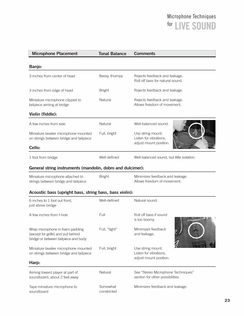
6 inches to 1 foot out front, just above bridge
A few inches from f-hole
Wrap microphone in foam padding (except for grille) and put behind bridge or between tailpiece and body
Miniature lavalier microphone mounted on strings between bridge and tailpiece
Harp:
Aiming toward player at part of soundboard, about 2 feet away
Tape miniature microphone to soundboard
Bassy, thumpy
Bright
Natural
Natural
Full, bright
Well-defined
Bright
Well-defined
Full
Full, “tight”
Full, bright
Natural
Somewhat constricted
Rejects feedback and leakage. Roll off bass for natural sound.
Rejects feedback and leakage.
Rejects feedback and leakage. Allows freedom of movement.
Well-balanced sound.
Use string mount. Listen for vibrations, adjust mount position.
Well-balanced sound, but little isolation.
Minimizes feedback and leakage. Allows freedom of movement.
Natural sound.
Roll off bass if sound is too boomy.
Minimizes feedback and leakage.
Use string mount. Listen for vibrations, adjust mount position.
See “Stereo Microphone Techniques” section for other possibilities.
Minimizes feedback and leakage.
General string instruments (mandolin, dobro and dulcimer):
Acoustic bass (upright bass, string bass, bass violin):
23

LIVE SOUNDMicrophone Techniquesfor
Microphone Placement Tonal Balance Comments
Grand piano:
12 inches above middle strings, 8 inches horizontally from hammers with lid off or at full stick
8 inches above treble strings, as above
Aiming intosound holes
6 inches over middle strings, 8 inches from hammers, with lid on short stick
Next to the underside of raised lid, centered on lid
Underneath the piano, aiming up at thesoundboard
Surface-mount microphone mounted on underside of lid over lower treblestrings, horizontally close to hammers for brighter sound, further from hammers for more mellow sound
Two surface-mount microphones positioned on the closed lid, under theedge at its keyboard edge, approximately2/3 of the distance from middle A to each end of the keyboard
Surface-mount microphone placed vertically on the inside of the frame, or rim, of thepiano, at ornear the apex of thepiano’scurved wall
Natural, well-balanced
Natural, well-balanced, slightly bright
Thin, dull, hard,constricted
Muddy, boomy,dull, lacks attack
Bassy, full
Bassy, dull, full
Bright, well-balanced
Bright, well-balanced,strong attack
Full, natural
Less pickup of ambience and leakage. Move microphone(s) farther from hammers to reduce attack and mechanical noises. Good coincident-stereo placement. See “Stereo Microphone Techniques” section.
Place one microphone over bass strings and oneover treble strings for stereo. Phase cancellationsmay occur if the recording is heard in mono.
Very good isolation. Sometimes sounds good forrock music. Boost mid-bass and treble for morenatural sound.
Improves isolation. Bass rolloff and some trebleboost required for more natural sound.
Unobtrusive placement.
Unobtrusive placement.
Excellent isolation. Experiment with lid height and microphone placement on piano lid for desired sounds.
Excellent isolation. Moving “low” mic away from keyboard six inches provides truer reproduction of the bass strings while reducingdamper noise. By splaying these two mics outward slightly, the overlap in the middle registers can be minimized.
Excellent isolation. Minimizes hammer anddamper noise. Best if used in conjunction with two surface-mount microphones mounted toclosed lid, as above.
24

25
LIVE SOUNDMicrophone Techniquesfor
Microphone Placement Tonal Balance Comments
Upright piano:
Just over open top, above treble strings
Just over open top, above bass strings
Inside top near the bass and treble stings
8 inches from bass side of soundboard
8 inches from treble side of soundboard
1 foot from center of soundboard on hard floor or one-foot-square plate on carpeted floor, aiming at piano. Soundboard should face into room
Aiming at hammers from front, severalinches away (remove front panel)
1 to 2 feet from bell. A couple of instruments can play into one microphone
Miniature microphone mounted on bell
Natural (but lacksdeep bass), picksup hammer attack
Slightly full ortubby, picks uphammer attack
Natural, picks uphammer attack
Full, slightly tubby,no hammer attack
Thin, constricted,no hammer attack
Natural, good presence
Bright, picks uphammer attack
On-axis to bellsounds bright; toone side soundsnatural or mellow
Bright
Good placement when only one microphone is used.
Mike bass and treble strings for stereo.
Minimizes feedback and leakage. Use two microphones for stereo.
Use this placement with the following placement for stereo.
Use this placement with the preceding placement for stereo.
Minimize pickup of floor vibrations by mounting microphone in low-profile shock-mounted microphone stand.
Mike bass and treble strings for stereo.
Close miking sounds “tight” and minimizes feedback and leakage. More distant placementgives fuller, more dramatic sound.
Maximum isolation.
Brass (trumpet, cornet, trombone, tuba):
The sound from these instruments is very directional. Placing the mic off axis with the bell of the instrument willresult in less pickup of high frequencies.

LIVE SOUNDMicrophone Techniquesfor
Microphone Placement Tonal Balance Comments
French horn:
Microphone aiming toward bell
A few inches from and aiming into bell
A few inches from sound holes
A few inchesabove bell and aiming atsound holes
Miniature microphonemounted on bell
A few inches from area between mouthpiece and first set of finger holes
A few inches behind player’s head, aiming at finger holes
Woodwinds (Oboe, bassoon, etc):
About 1 foot from sound holes
A few inches from bell
Natural
Bright
Warm, full
Natural
Bright, punchy
Natural, breathy
Natural
Natural
Bright
Watch out for extreme fluctuations on VU meter.
Minimizes feedback and leakage.
Picks up fingering noise.
Good recording technique.
Maximum isolation, up-front sound.
Pop filter or windscreen may be required on microphone.
Reduces breath noise.
Provides well-balanced sound.
Minimizes feedback and leakage.
Flute:
The sound energy from a flute is projected both by the embouchure and by the first open fingerhole. For good pickup, place the mic as close as possible to the instrument. However, if the mic is too close to the mouth,breath noise will be apparent. Use a windscreen on the mic to overcome this difficulty.
Saxophone:
With the saxophone, the sound is fairly well distributed between the finger holes and the bell. Miking close to the finger holes will result in key noise. The soprano sax must be considered separately because its bell does not curveupward. This means that, unlike all other saxophones, placing a microphone toward the middle of the instrument will not pick-up the sound from the key holes and the bell simultaneously. The saxophone has sound characteristicssimilar to the human voice. Thus, a shaped response microphone designed for voice works well.
26

27
LIVE SOUNDMicrophone Techniquesfor
Microphone Placement Tonal Balance Comments
Harmonica:
Very close to instrument
Accordion:
Miniature microphone mounted internally
4 inches from grille cloth at center ofspeaker cone
1 inch from grille cloth at center of speaker cone
Off-center with respect to speaker cone
3 feet from center of speaker cone
Miniature microphone draped over amp in front of speaker
Microphone placed behind open back cabinet
Bass guitar amplifier/speaker:
Mike speaker as described in Electric Guitar Amplifier section
Mike speaker as described in Electric Guitar Amplifier section
Full, bright
Emphasizedmidrange
Natural, well-balanced
Bassy
Dull or mellow
Thin, reduced bass
Emphasizedmidrange
Depends on position
Depends on placement
Depends on brand of piano
Minimizes feedback and leakage. Microphone may be cupped in hands.
Minimizes feedback and leakage. Allows freedom of movement.
Small microphone desk stand may be used if loudspeaker is close to floor.
Minimizes feedback and leakage.
Microphone closer to edge of speaker cone resultsin duller sound. Reduces amplifier hiss noise.
Picks up more room ambience and leakage.
Easy setup, minimizes leakage.
Can be combined with mic in front of cabinet, but be careful of phase cancellation.
Improve clarity by cutting frequencies around 250 Hz and boosting around 1,500 Hz.
Roll off bass for clarity, roll off highs to reduce hiss.
Electric guitar amplifier/speaker:
The electric guitar has sound characteristics similar to the human voice. Thus, a shaped response microphone designed for voice works well.
Electric keyboard amplifier/speakers:

28
LIVE SOUNDMicrophone Techniquesfor
Microphone Placement Tonal Balance Comments
Leslie organ speaker:
Aim one microphone into top louvers 3 inches to 1 foot away
Mike top louvers and bottom bassspeaker 3 inches to 1 foot away
Mike top louvers with two microphones,one close to each side. Pan to left andright. Mike bottom bass speaker 3 inchesto 1 foot away and pan its signal to center
Natural, lacks deep bass
Natural, well-balanced
Natural, well-balanced
Good one-mike pickup.
Excellent overall sound.
Stereo effect.
Drum kit:
In most sound reinforcement systems, the drum set is miked with each drum having its own mic. Using microphoneswith tight polar patterns on toms helps to isolate the sound from each drum. It is possible to share one mic with twotoms, but then, a microphone with a wider polar pattern should be used. The snare requires a mic that can handlevery high SPL, so a dynamic mic is usually chosen. To avoid picking up the hi-hat in the snare mic, aim the null of thesnare mic towards the hi-hat. The brilliance and high frequencies of cymbals are picked up best by a flat responsecondenser mic.
Front View Top View
1. Overhead-Cymbals:
One microphone over center of drum set, about 1 foot above drummer’s head (Position A); or use two spaced or crossed microphones for stereo (Positions A or B). See “Stereo Microphone Techniques” section
Natural; sounds likedrummer hears set
Picks up ambience and leakage. For cymbalpickup only, roll off low frequencies. Boost at10,000 Hz for added sizzle. To reduce excessivecymbal ringing, apply masking tape in radial strips from bell to rim.

LIVE SOUNDMicrophone Techniquesfor
Microphone Placement Tonal Balance Comments
2. Snare drum:
Just above top head at edge of drum,aiming at top head. Coming in fromfront of set on boom (Position C); or miniature microphone mounted directly on drum
Remove front head if necessary. Mount microphone on boom arm inside drum a few inches from beaterhead, about 1/3 of way in from edge of head (Position D); or place surface-mount microphone inside drum, ondamping material, with microphone element facing beater head
4. Tom-toms:
One microphone between every two tom-toms, close to top heads (Position E); or one microphone justabove each tom-tom rim, aiming attop head (Position F); or one microphone inside each tom-tom with bottom head removed; or miniature microphone mounted directly on drum
5. Hi-hat:
Aim microphone down towards the cymbals, a few inches over edgeaway from drummer (Position G). Or angle snare drum microphoneslightly toward hi-hat to pick up both snare and hi-hat
Full, smooth
Full, good impact
Full, good impact
Natural,bright
Tape gauze pad or handkerchiefon top head to tighten sound.Boost at 5,000 Hz for attack, if necessary.
Put pillow or blanket on bottom of drum against beater head totighten beat. Use wooden beater,or loosen head, or boost around2,500 Hz for more impact andpunch.
Inside drum gives best isolation. Boost at 5,000 Hz for attack, if necessary.
Place microphone or adjustcymbal height so that puff of air from closing hi-hat cymbalsmisses mike. Roll off bass to reduce low-frequency leakage.To reduce hi-hate leakage intosnare-drum microphone, usesmall cymbals vertically spaced1/2” apart.
3. Bass drum (kick drum):
Placing a pad of paper towels where the beater hits the drum will lessen boominess. If you get rattling or buzzingproblems with the drum, put masking tape across the drum head to damp out these nuisances. Placing the mic offcenter will pick up more overtones.
29
30
LIVE SOUNDMicrophone Techniquesfor
Microphone Placement Tonal Balance Comments
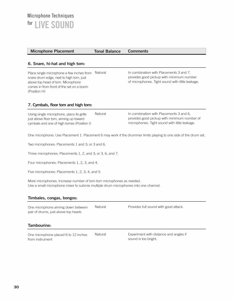
6. Snare, hi-hat and high tom:
Place single microphone a few inches fromsnare drum edge, next to high tom, justabove top head of tom. Microphone comes in from front of the set on a boom(Position H)
7. Cymbals, floor tom and high tom:
Using single microphone, place its grillejust above floor tom, aiming up towardcymbals and one of high tomes (Position I)
Natural
Natural
In combination with Placements 3 and 7, provides good pickup with minimum number of microphones. Tight sound with little leakage.
In combination with Placements 3 and 6, provides good pickup with minimum number ofmicrophones. Tight sound with little leakage.
One microphone: Use Placement 1. Placement 6 may work if the drummer limits playing to one side of the drum set.
Two microphones: Placements 1 and 3; or 3 and 6.
Three microphones: Placements 1, 2, and 3; or 3, 6, and 7.
Four microphones: Placements 1, 2, 3, and 4.
Five microphones: Placements 1, 2, 3, 4, and 5.
More microphones: Increase number of tom-tom microphones as needed. Use a small microphone mixer to submix multiple drum microphones into one channel.
Timbales, congas, bongos:
One microphone aiming down betweenpair of drums, just above top heads
Tambourine:
One microphone placed 6 to 12 inchesfrom instrument
Natural
Natural
Provides full sound with good attack.
Experiment with distance and angles ifsound is too bright.

31
LIVE SOUNDMicrophone Techniquesfor
Microphone Placement Tonal Balance Comments
Steel Drums:
Tenor, Second Pan, GuitarOne microphone placed 4 inches above each pan
Microphone placed underneath pan
Cello, BassOne microphone placed 4 - 6 inchesabove each pan
Xylophone, marimba, vibraphone:
Two microphones aiming down toward instrument, about 1 1/2 feet above it,spaced 2 feet apart, or angled 135ºapart with grilles touching
Glockenspiel:
One microphone placed 4 - 6 inchesabove bars
Bright, with plentyof attack
Natural
Natural
Bright, with lots of attack
Allow clearance for movement of pan.
Decent if used for tenor or second pans. Too boomy with lower voiced pans.
Can double up pans to a single microphone.
Pan two microphones to left and right for stereo.See “Stereo Microphone Techniques” section.
For less attack, use rubber mallets instead of metalmallets. Plastic mallets will give a medium attack.
Downstage: Surface-mount microphones along frontof stage aimed upstage, one microphonecenter stage; use stage left and stageright mics as needed, approximately 1per 10-15 feet
Upstage:Microphones suspended 8 -10 feet above stage aimed upstage, one microphone center stage; use stage left and stage right mics as needed, approximately 1 per 10-15 feet
Spot pickup: Use wireless microphones on principalactors; mics concealed in set; “shotgun”microphones from above or below
Voice range, semi-distant
Voice range, semi-distant
Voice range, on mic
Use flat response, unidirectional microphones.Use minimum number of microphones needed toavoid overlapping pickup area. Use shock mount if needed.
Use flat response, unidirectional microphones.Use minimum number of microphones needed toavoid overlapping pickup area.
Multiple wireless systems must utilize different frequencies. Use lavaliere or handheld microphones as appropriate.
Stage area miking Tonal Balance Comments

Comments
Tends to provide accurate imagelocalization.
Near-Coincident Techniques
Microphones angled and spacedapart 6 to 10 inches betweengrilles. Examples: 1100 angled,7-inch spacing
MS (Mid-Side)
A front-facing cardioid cartridgeand a side-facing bidirectional cartridge are mounted in a singlehousing. Their outputs are combined in a matrix circuit toyield discrete left and right outputs.
Comments
Provides good stereo spread, excellent stereo imaging and localization. Some types allow adjustable stereo control. Mono-compatible.
Stereo Microphone Techniques
These methods are recommended for pickup of orchestras,bands, choirs, pipe organs, quartets, soloists. They alsomay work for jazz ensembles, and are often used on overhead drums and close-miked piano.
Use two microphones mounted on a single stand with astereo microphone stand adapter (such as the ShureA27M). Or mount 2 or 3 microphones on separate stands.Set the microphones in the desired stereo pickup arrangement (see below).
For sound reinforcement, stereo mic techniques are onlywarranted for a stereo sound system and even then, theyare generally only effective for large individual instruments,such as piano or miramba, or small instrument groups,such as drum kit, string section or vocal chorus. Relativelyclose placement is necessary to achieve useable gain-before-feedback.
32
LIVE SOUNDMicrophone Techniquesfor
Coincident Techniques
Microphone diaphragms closetogether and aligned vertically;microphones angled apart. Example: 1350 angling (X-Y).
Comments
Tends to provide a narrow stereospread (the reproduced ensembledoes not always spread all theway between the pair of playbackloud-speakers). Good imaging.Mono-compatible.

33
LIVE SOUNDMicrophone Techniquesfor
Three microphones spaced several feet apart horizontally,aiming straight ahead toward ensemble. Center microphonesignal is split equally to bothchannels. Example: Microphones 5 feet apart.
Improved localization comparedto two spaced microphones.
Spaced Techniques
Two microphones spaced several feet apart horizontally,both aiming straight ahead toward ensemble. Example: Microphones 3 to 10 feet apart.
Comments
Tends to provide exaggerated separation unless microphonespacing is 3 feet. However, spacing the microphones 10 feetapart improves overall coverage.Produces vague imaging for off-center sound sources. Provides a “warm” sense of ambience.
Musical Ensemble
(Top View)
Musical Ensemble
(Top View)

34
LIVE SOUNDMicrophone Techniquesfor
Shure Microphone Selection Guide
Se l e c t i o n Gu i d e
Live Vocals
KSM9Beta58ASM58Beta54Beta87ABeta87CSM87ASM86PG5855SH Series II WH30
Studio Vocals
KSM44 KSM32KSM27KSM9SM7ABeta87ABeta87CSM87ASM86
StudioEnsemble Vocals
KSM44 KSM32KSM27KSM141KSM137KSM109
Live Choirs
MX202EZOSM81SM94PG81
Karaoke
SM58SSM48S565PG58PG48
Spoken Word
Beta53SM48PG48
Studio Instrument
KSM141KSM137KSM109KSM44 KSM32KSM27SM81
Orchestra
KSM141KSM137KSM109KSM44 KSM32KSM27SM81 SM94PG81
Strings
KSM141KSM137KSM109KSM44KSM32KSM27SM81 SM94PG81Beta98S
Woodwinds
KSM44 KSM32KSM27KSM141KSM137KSM109SM81 Beta98H/C Beta98 S1
PG81
Brass / Saxophone
Beta98H/C KSM44 KSM32KSM27Beta57A Beta98 S Beta56 A SM57PG56 PG57
Acoustic Guitar
KSM141KSM137KSM109KSM44KSM32KSM27SM81 Beta57A SM57PG81PG57
Acoustic Bass
KSM44KSM32KSM27KSM141KSM137KSM109Beta52A SM81 SM94PG81
Guitar Amp
Beta56ABeta57A SM57KSM141KSM137KSM109KSM44 KSM32KSM27SM94PG57
Bass Amp
Beta52A SM7B Beta57A Beta56ASM57PG52SM94PG57PG81
Leslie Speaker
KSM44KSM32KSM27Beta91Beta57ABeta56ASM57
Piano / Organ
KSM44KSM32KSM27KSM141KSM137KSM109SM81 Beta91PG81SM94MX202
Harmonica
520DX SM57SM58PG57
Kick Drum
Beta52A Beta91 PG52 Beta57ASM57
Snare Drum2
Beta57A2,3
Beta56A2
SM572,3
PG56PG572,3
Rack / FloorToms
Beta98D/SBeta57A2,3
Beta56A2
SM572,3
PG56 PG572,3
Congas
Beta98D/S Beta56A2
Beta57A2
SM572
PG56PG572
Cymbals
KSM141KSM137KSM109KSM44KSM32KSM27SM81 SM94PG81
Mallets
KSM44KSM32KSM27KSM141KSM137KSM109SM81SM94PG81
(Percussion)
KSM141KSM137KSM109KSM44KSM32KSM27SM81Beta57ASM57PG57
Sampling / Effects
KSM44KSM32KSM27 KSM141KSM137KSM109VP88SM81 SM94
Live StereoRecording
KSM141(pair)4
KSM137(pair)4
KSM109(pair)4
KSM44(pair)4
KSM32(pair)4
KSM27(pair)4
SM81(pair)4
SM94(pair)4
VP88 (M-S stereo)
Voice-Over
KSM44KSM32KSM27SM7BBeta58A SM58SM815
Beta87CBeta87A
Vocal Instrument Drum Other
3A50D enables microphoneto mount on rim.
4For optimum flexibility, use A27Mstereo microphone mount.
5With A81G.
2A56D enables microphoneto mount on rim.
1Bell mounted with A98KCS clamp.

3-to-1 Rule-When using multiple microphones, the distance between microphones should be at least 3 times the distance from each microphone to its intended sound source.
Absorption-The dissipation of sound energy by lossesdue to sound absorbent materials.
Active Circuitry-Electrical circuitry which requires powerto operate, such as transistors and vacuum tubes.
Ambience-Room acoustics or natural reverberation.
Amplitude-The strength or level of sound pressure orvoltage.
Audio Chain-The series of interconnected audio equipment used for recording or PA.
Backplate-The solid conductive disk that forms the fixed half of a condenser element.
Balanced-A circuit that carries information by means oftwo equal but opposite polarity signals, on two conductors.
Bidirectional Microphone-A microphone that picks up equally from two opposite directions. The angle ofbest rejection is 90 deg. from the front (or rear) of the microphone, that is, directly at the sides.
Boundary/Surface Microphone-A microphone designedto be mounted on an acoustically reflective surface.
Cardioid Microphone-A unidirectional microphone withmoderately wide front pickup (131 deg.). Angle of bestrejection is 180 deg. from the front of the microphone,that is, directly at the rear.
Cartridge (Transducer)-The element in a microphonethat converts acoustical energy (sound) into electrical energy (the signal).
Close Pickup-Microphone placement within 2 feet of asound source.
Comb Filtering-An interference effect in which the frequency response exhibits regular deep notches.
Condenser Microphone-A microphone that generates an electrical signal when sound waves vary the spacingbetween two charged surfaces: the diaphragm and thebackplate.
Critical Distance-In acoustics, the distance from a soundsource in a room at which the direct sound level is equalto the reverberant sound level.
Current-Charge flowing in an electrical circuit. Analogous to the amount of a fluid flowing in a pipe.
Decibel (dB)-A number used to express relative outputsensitivity. It is a logarithmic ratio.
Diaphragm-The thin membrane in a microphone whichmoves in response to sound waves.
Diffraction-The bending of sound waves around an object which is physically smaller than the wavelength of the sound.
Direct Sound-Sound which travels by a straight pathfrom a sound source to a microphone or listener.
Distance Factor-The equivalent operating distance of adirectional microphone compared to an omnidirectionalmicrophone to achieve the same ratio of direct to reverberant sound.
Distant Pickup-Microphone placement farther than 2 feet from the sound source.
Dynamic Microphone-A microphone that generates anelectrical signal when sound waves cause a conductor tovibrate in a magnetic field. In a moving-coil microphone,the conductor is a coil of wire attached to the diaphragm.
Dynamic Range-The range of amplitude of a soundsource or the range of sound level that a microphone can successfully pick up.
Echo-Reflection of sound that is delayed long enough(more than about 50 msec.) to be heard as a distinctrepetition of the original sound.
Electret-A material (such as Teflon) that can retain a permanent electric charge.
EQ-Equalization or tone control to shape frequency response in some desired way.
Feedback-In a PA system consisting of a microphone,amplifier, and loudspeaker feedback is the ringing orhowling sound caused by amplified sound from the loud-speaker entering the microphone and being re-amplified.
35
LIVE SOUNDMicrophone Techniquesfor
G l o s s a r y

Flat Response-A frequency response that is uniform andequal at all frequencies.
Frequency-The rate of repetition of a cyclic phenomenonsuch as a sound wave.
Frequency Response Tailoring Switch-A switch on a microphone that affects the tone quality reproduced bythe microphone by means of an equalization circuit.(Similar to a bass or treble control on a hi-fi receiver.)
Frequency Response-A graph showing how a microphoneresponds to various sound frequencies. It is a plot ofelectrical output (in decibels) vs. frequency (in Hertz).
Fundamental-The lowest frequency component of acomplex waveform such as musical note. It establishesthe basic pitch of the note.
Gain-Amplification of sound level or voltage.
Gain-Before-Feedback-The amount of gain that can be achieved in a sound system before feedback or ringing occurs.
Harmonic-Frequency components above the fundamentalof a complex waveform. They are generally multiples of thefundamental which establish the timbre or tone of the note.
Hypercardioid-A unidirectional microphone with tighterfront pickup (105 deg.) than a supercardioid, but withmore rear pickup. Angle of best rejection is about 110deg. from the front of the microphone.
Impedance-In an electrical circuit, opposition to the flow of alternating current, measured in ohms. A high impedance microphone has an impedance of 10,000ohms or more. A low impedance microphone has an impedance of 50 to 600 ohms.
Interference-Destructive combining of sound waves orelectrical signals due to phase differences.
Inverse Square Law-States that direct sound levels increase (or decrease) by an amount proportional to the square of the change in distance.
Isolation-Freedom from leakage; ability to reject unwanted sounds.
Leakage-Pickup of an instrument by a microphone intended to pick up another instrument. Creative leakageis artistically favorable leakage that adds a “loose” or“live” feel to a recording.
NAG-Needed Acoustic Gain is the amount of gain that asound system must provide for a distant listener to hearas if he or she was close to the unamplified sound source.
Noise-Unwanted electrical or acoustic interference.
Noise Canceling-A microphone that rejects ambient ordistant sound.
NOM-Number of open microphones in a sound system.Decreases gain-before-feedback by 3dB everytime NOMdoubles.
Omnidirectional Microphone-A microphone that picksup sound equally well from all directions.
Overload-Exceeding the signal level capability of a microphone or electrical circuit.
PAG-Potential Acoustic Gain is the calculated gain that asound system can achieve at or just below the point offeedback.
Phantom Power-A method of providing power to theelectronics of a condenser microphone through the microphone cable.
Phase-The “time” relationship between cycles of different waves.
Pickup Angle / Coverage Angle-The effective arc of coverage of a microphone, usually taken to be within the 3dB down points in its directional response.
Pitch-The fundamental or basic frequency of a musicalnote.
Polar Pattern (Directional Pattern, Polar Response)-A graph showing how the sensitivity of a microphonevaries with the angle of the sound source, at a particularfrequency. Examples of polar patterns are unidirectionaland omnidirectional.
Polarization-The charge or voltage on a condenser microphone element.
36
LIVE SOUNDMicrophone Techniquesfor
G l o s s a r y

Pop Filter-An acoustically transparent shield around amicrophone cartridge that reduces popping sounds.Often a ball-shaped grille, foam cover or fabric barrier.
Pop-A thump of explosive breath sound producedwhen a puff of air from the mouth strikes the microphone diaphragm. Occurs most often with “p,”“t,” and “b” sounds.
Presence Peak-An increase in microphone output in the“presence” frequency range of 2000 Hz to 10,000 Hz.A presence peak increases clarity, articulation, apparentcloseness, and “punch.”
Proximity Effect-The increase in bass occurring withmost unidirectional microphones when they are placedclose to an instrument or vocalist (within 1 ft.). Does notoccur with omnidirectional microphones.
Rear Lobe-A region of pickup at the rear of a supercardioid or hypercardioid microphone polar pattern. A bidirectional microphone has a rear lobe equal to its front pickup.
Reflection-The bouncing of sound waves back from an object or surface which is physically larger than thewavelength of the sound.
Refraction-The bending of sound waves by a change in the density of the transmission medium, such as temperature gradients in air due to wind.
Resistance-The opposition to the flow of current in anelectrical circuit. It is analogous to the friction of fluidflowing in a pipe.
Reverberation-The reflection of a sound a sufficientnumber of times that it becomes non-directional and persists for some time after the source has stopped. The amount of reverberation depends on the relativeamount of sound reflection and absorption in the room.
Rolloff-A gradual decrease in response below or abovesome specified frequency.
Sensitivity-The electrical output that a microphone produces for a given sound pressure level.
Shaped Response-A frequency response that exhibitssignificant variation from flat within its range. It is usually designed to enhance the sound for a particularapplication.
Sound Chain-The series of interconnected audio equipment used for recording or PA.
Sound Reinforcement-Amplification of live soundsources.
Speed of Sound-The speed of sound waves, about 1130 feet per second in air.
SPL-Sound Pressure Level is the loudness of sound relative to a reference level of 0.0002 microbars.
Standing Wave-A stationary sound wave that is reinforced by reflection between two parallel surfacesthat are spaced a wavelength apart.
Supercardioid Microphone-A unidirectional microphonewith tighter front pickup angle (115 deg.) than a cardioid,but with some rear pickup. Angle of best rejection is 126 deg. from the front of the microphone, that is, 54 deg. from the rear.
Timbre-The characteristic tone of a voice or instrument; a function of harmonics.
Transducer-A device that converts one form of energy toanother. A microphone transducer (cartridge) convertsacoustical energy (sound) into electrical energy (theaudio signal).
Transient Response-The ability of a device to respond to a rapidly changing input.
Unbalanced-A circuit that carries information by meansof one signal on a single conductor.
Unidirectional Microphone-A microphone that is most sensitive to sound coming from a single direction-in front of the microphone. Cardioid, supercardioid, and hypercardioid microphones are examples of unidirectional microphones.
Voice Coil-Small coil of wire attached to the diaphragm of a dynamic microphone.
Voltage-The potential difference in an electric circuit.Analogous to the pressure on fluid flowing in a pipe.
Wavelength-The physical distance between the start and end of one cycle of a soundwave.
37
LIVE SOUNDMicrophone Techniquesfor
G l o s s a r y

Rick WallerNow residing in the Chicago area, Rick grew up near Peoria,
Illinois. An interest in the technical and musical aspects of audio
has led him to pursue a career as both engineer and musician.
He received a BS degree in Electrical Engineering from the
University of Illinois at Urbana/Champaign, where he specialized
in acoustics, audio synthesis and radio frequency theory. Rick is
an avid keyboardist, drummer and home theater hobbyist and
has also worked as a sound engineer and disc jockey. Currently
he is an associate in the Applications Engineering Group at Shure
Incorporated. In this capacity Rick provides technical support to
domestic and international customers, writing and conducting
seminars on wired and wireless microphones, mixers and other
audio topics.
John BoudreauJohn, a lifelong Chicago native, has had extensive experience
as a musician, a recording engineer, and a composer. His desire
to better combine the artistic and technical aspects of music led
him to a career in the audio field.
Having received a BS degree in Music Business from
Elmhurst College, John performed and composed for both a Jazz
and a Rock band prior to joining Shure Incorporated in 1994 as
an associate in the Applications Engineering group. At Shure,
John led many audio product training seminars and clinics, with
an eye to helping musicians and others affiliated with the field
use technology to better fulfill their artistic interpretations.
No longer a Shure associate, John continues to pursue his
interests as a live and recorded sound engineer for local bands
and venues, as well as writing and recording for his own band.
Tim VearTim is a native of Chicago who has come to the audio field
as a way of combining a lifelong interest in both entertainment
and science. He has worked as an engineer in live sound,
recording and broadcast, has operated his own recording studio
and sound company, and has played music professionally since
high school.
At the University of Illinois, Urbana-Champaign, Tim earned
a BS in Aeronautical and Astronautical Engineering with a minor
in Electrical Engineering. During this time he also worked as chief
technician for both the Speech and Hearing Science and
Linguistics departments.
In his tenure at Shure Incorporated, Tim has served in a
technical support role for the sales and marketing departments,
providing product and applications training for Shure customers,
dealers, installers, and company staff. He has presented
seminars for a variety of domestic and international audiences,
including the National Systems contractors Association, the Audio
Engineering Society and the Society of Broadcast Engineers.
Tim has authored several publications for Shure Incorporated and
his articles have appeared in Recording Engineer/Producer, Live
Sound Engineering, Creator, and other publications.
38
LIVE SOUNDMicrophone Techniquesfor

www.shure.com
United States:Shure Incorporated5800 West Touhy AvenueNiles, IL 60714-4608 USA
Phone: 847-600-2000Fax: 847-600-1212Email: [email protected]
Europe, Middle East, Africa:Shure Europe GmbHWannenäckerstr. 28,74078 Heilbronn, Germany
Phone: 49-7131-72140Fax: 49-7131-721414Email: [email protected]
Asia, Pacifi c:Shure Asia Limited3/F, Citicorp Centre18 Whitfi eld RoadCauseway Bay, Hong Kong
Phone: 852-2893-4290Fax: 852-2893-4055Email: [email protected]
Canada, Latin America,Caribbean:Shure Incorporated5800 West Touhy AvenueNiles, IL 60714-4608 USA
Phone: 847-600-2000Fax: 847-600-6446Email: [email protected]
©2007 Shure Incorporated AL0000
Additional Shure Publications Available:
Printed or electronic versions of the following guides are available free of charge.
To obtain your complimentary copies, call one of the phone numbers listed below or
visit www.shure.com.
• Selection and Operation of Wireless Microphone Systems
• Audio Systems Guide for Video Production
• Audio Systems Guide for Houses of Worship
• Microphone Techniques for Studio Recording
Our Dedication to Quality Products
Shure offers a complete line of microphones and wireless microphone systems for everyone
from first-time users to professionals in the music industry–for nearly every possible application.
For over eight decades, the Shure name has been synonymous with quality audio.
All Shure products are designed to provide consistent, high-quality performance under the
most extreme real-life operating conditions.
©2007 Shure Incorporated AL1266H 10M 12/07