Micromechanical Modeling of Strength and Damage of Fiber ... · Micromechanical Modeling of...
54
Micromechanical Modeling of Strength and Damage of Fiber Reinforced Composites Leon Mishnaevsky Jr. and Povl Brøndsted Annual Report on EU FP6 Project UpWind Integrated Wind Turbine Design (WP 3.2) Period: 1.4.2006-30.3.2007 Risø National Laboratory Technical University of Denmark Roskilde, Denmark March 2007
Transcript of Micromechanical Modeling of Strength and Damage of Fiber ... · Micromechanical Modeling of...

Micromechanical Modeling of Strength and Damage of Fiber
Reinforced Composites
Leon Mishnaevsky Jr. and Povl Brøndsted
Annual Report on EU FP6 Project UpWind Integrated Wind Turbine Design (WP 3.2)
Period: 1.4.2006-30.3.2007
Risø National Laboratory Technical University of Denmark
Roskilde, Denmark March 2007

Author: Leon Mishnaevsky Jr., Povl Brøndsted Title: Micromechanical Modeling of Strength and Damage of Fiber Reinforced Composites
Risø-R-1601(EN) March 2007
Department:Materials Research Department
ISSN 0106-2840 ISBN 978-87-550-3588-1
Contract no.: 019945 Group's own reg. no.: (Føniks PSP-element)
Sponsorship: EU UpWind
Cover :
Pages: 55 Tables: References: 120
Abstract (max. 2000 char.): The report for the first year of the EU UpWind project includes three parts: overview of concepts and methods of modelling of mechanical behavior, deformation and damage of unidirectional fiber reinforced composites, development of computational tools for the automatic generation of 3D micromechanical models of fiber reinforced composites, and micromechanical modelling of damage in FRC, and phenomenoligical analysis of the effect of frequency of cyclic loading on the lifetime and damage evolution in materials.
Information Service Department Risø National Laboratory Technical University of Denmark P.O.Box 49 DK-4000 Roskilde Denmark Telephone +45 46774004 [email protected] Fax +45 46774013 www.risoe.dk

Risø-R-1601(EN) 3
Contents
Preface 4
Overview 5
Modelling of damage and fracture of unidirectional fiber reinforced composites: a review
6
Automatic generation of 3D microstructural models of unidirectional fiber reinforced composites: program, testing and application to damage simulations
26
Modeling of fatigue damage evolution on the basis of the kinetic concept of strength
40

4 Risø-R-1601(EN)
1 Preface The purpose of the Work Package 3.2 of UpWind is to gain knowledge and to develop fundamental understanding of materials of the strength, mechanical behaviour and fatigue resistance of composite materials used in blades for large scale wind turbines. This should be achieved on the basis of the development of micromechanical models of deformation behavior, and damage evolution of the composites, and implementation of the models in easy-to-use computational predictive/design tools.
At this stage of the work, the following subtasks are solved:
- Analysis of existing concepts and techniques of modeling of strength and damage of fiber reinforced composites,
- Development of computational tools for the automatic generation of 3D micromechanical models of fiber reinforced composites, taking into account the random arrangement of fibers and interphases,
- Development of a computational model of fiber failure as damage evolution in a section of a fiber, and the
- Computational experiments: analysis of the interaction between different damage modes (fiber cracking, interface damage and matrix cracks) in materials with strongly nonlinear ductile matrix and viscoelastic polymer matrix,
- Modeling of the effect of the fatigue frequency (in the low frequency region) on the fatigue damage evolution and lifetime of materials.
Risø-R-1601(EN) 5
2 Overview
Overview of concepts and methods of modelling of mechanical behavior, deformation and damage of unidirectional fiber reinforced composites. An overview of methods of the mathematical modelling of deformation, damage and fracture in fiber reinforced composites is presented. The models are classified into 4 main groups: shear lag-based, analytical models, fiber bundle model and its generalizations, fracture mechanics and continuum damage mechanics based models and numerical micromechanical models. The advantages and preferable areas of application of each approach are discussed.
Development of computational tools for the automatic generation of 3D micromechanical models of fiber reinforced composites, and micromechanical damage modelling. A computer code for automatic generation of 3D multifiber micromechanical models of composites with random fiber arrangement is developed. The fiber/matrix interface damage is modeled as a finite element weakening in the interphase layers. The fiber cracking is simulated as the damage evolution in the randomly placed damageable layers in the fibers, using the ABAQUS subroutine User Defined Field.
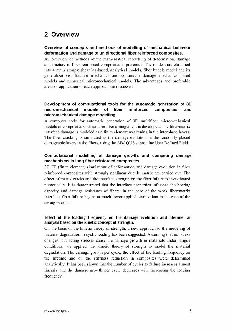
Computational modelling of damage growth, and competing damage mechanisms in long fiber reinforced composites. 3D FE (finite element) simulations of deformation and damage evolution in fiber reinforced composites with strongly nonlinear ductile matrix are carried out. The effect of matrix cracks and the interface strength on the fiber failure is investigated numerically. It is demonstrated that the interface properties influence the bearing capacity and damage resistance of fibers: in the case of the weak fiber/matrix interface, fiber failure begins at much lower applied strains than in the case of the strong interface.
Effect of the loading frequency on the damage evolution and lifetime: an analysis based on the kinetic concept of strength. On the basis of the kinetic theory of strength, a new approach to the modeling of material degradation in cyclic loading has been suggested. Assuming that not stress changes, but acting stresses cause the damage growth in materials under fatigue conditions, we applied the kinetic theory of strength to model the material degradation. The damage growth per cycle, the effect of the loading frequency on the lifetime and on the stiffness reduction in composites were determined analytically. It has been shown that the number of cycles to failure increases almost linearly and the damage growth per cycle decreases with increasing the loading frequency.

6 Risø-R-1601(EN)
3 Modelling of damage and fracture of unidirectional fiber reinforced composites: a
review
Abstract: A overview of methods of the mathematical modelling of deformation, damage and fracture in fiber reinforced composites is presented. The models are classified into 4 main groups: shear lag-based, analytical models, fiber bundle model and its generalizations, fracture mechanics based models and numerical micromechanical models. The advantages and preferable areas of application of each approach are discussed. 1. Introduction Fiber-reinforced composites are often characterized by their high specific strength and specific modulus parameters (i.e., strength to weight ratios), and are widely used for applications in low-weight components. The high strength and damage resistance of the composites are very important for a number of practical applications. In order to predict the strength and other properties of composites, a number of mathematical models of deformation, damage and failure of fiber reinforced composites have been developed. The purpose of this work is to review different models of deformation, damage and failure of fiber reinforced composites, to compare their strong sides and areas of application. The micromechanisms of damage in fiber reinforced composites (FRC) can be described as follows (Mishnaevsky Jr, 2007). If a fiber reinforced composite with ductile matrix is subject to longitudinal tensile loading, the main part of the load is born by the fibers, and they tend to fail first. After weakest fibers fail, the loading on remaining intact fibers increases. That may cause the failure of other, first of all, neighboring fibers. The cracks in the fibers cause higher stress concentration in the matrix, what can lead to the matrix cracking. However, if the fiber/matrix interface is weak, the crack will extend and grow along the interface. In the case of ceramic and other brittle matrix composites, the crack is formed initially in the matrix. If intact fibers are available behind the crack front and they are connecting the crack faces, the crack bridging mechanism is operative. In this case, the load is shared by the bridging fibers and crack tip, and the stress intensity factor on the crack tip is reduced. A higher amount of bringing fibers leads to the lower stress intensity factor on the crack tip, and the resistance to crack growth increases with increasing the crack length (R-curve behavior) (Sørensen, and Jacobsen, 1998, 2000) The extension of a crack, bridged by intact fibers, leads to the debonding and pull out of fibers that increase the fracture toughness of the material. In this work, we seek to apply the methods of the computational micromechanics to analyze the interaction between different damage mechanisms, and the effect of the phase and interface properties on the damage evolution in fiber reinforced composites.
2. Shear lag based models and load redistribution schemas The shear lag model, developed by Cox in 1952 is one of the most often used approaches in the analysis of strength and damage of fiber reinforced composites. This model is often employed to analyze the load redistribution in fiber reinforced composites, resulting from failure of one or several fibers. This redistribution is

Risø-R-1601(EN) 7
described in the framework of various load sharing models. In the fiber bundle model, developed by Daniels (1945), the global load sharing schema (GLS) was assumed: i.e., the load, which was born by a broken fiber, is equally re-distributed over all the remaining intact fibers in the cross-section of the composite. As noted by Zhou and Wagner (1999), the GLS model is applicable only to a loose fiber bundle, with no matrix between the fibers. In the case of fibers which are bound together by the matrix, other models of the load sharing should be used. For the qualitative description of the load redistribution after the fiber failure, SCF (stress concentration factor) is introduced as a ratio between the local stress in an intact fiber (which is equal to the overload at the fiber related with the fiber break, and applied stress) and the applied stress (Zhou and Wagner, 1999). Harlow and Phoenix (1978) proposed the local load sharing (LLS) model, in which the extra-load, related with the failed fiber(s), is transferred to two nearest neighbors of the fiber(s). Hedgepeth (1961) was first to apply the shear lag model to a multifiber system. He studied the stress distribution around broken fibers in 2D unidirectional composites with infinite array of fibers. Hedgepeth and van Dyke (1967) generalized the elastic model by Hedgepeth to the three-dimensional case and included the elastic-plastic matrix into the model. Considering an array of parallel fibers under axial loading, bonded to the matrix, they determined the average SCF in a fiber after the failure of k adjacent fibers:
∏= +
+=
k
i iiSCF
1 1222
(1)
Curtin (1991) noted that the problem of independent and successive fiber fractures under GLS condition is reduced to the problem of failure of single fiber in the matrix. Considering the cumulative number of defects in fibers from the Weibull distribution of fiber strengths, he estimated the ultimate strength of the composite as a function of the sliding resistance, and parameters of the Weibull distribution of the fiber strengths. The shear lag model was used by Wagner and Eitan (1993) to study the redistribution of stress from a failed fiber to its neighbors. They determined SCF for the case of load redistribution after one single fiber in a 2D unidirectional composite is broken, and demonstrated that the “local effect of a fiber break on the nearest neighbors is much milder than previously calculated, both as a function of the interfiber distance and of the number of adjacent broken fibers”. Zhou and Wagner (1999) proposed a model of stress redistribution after the fiber failure, which incorporated the effects of fiber/matrix debonding and fiber/matrix interfacial friction. The interfacial friction in the debonding region was calculated as proportional to the far-field longitudinal stress in the fiber. It was observed that SCF decreases with increasing interfiber distance. The effects of multiple fiber breaks and their interaction on the stress distribution and strength of composites can be analyzed with the use of the break influence superposition (BIS) technique. The BIS technique was developed by Sastry and Phoenix (1993) on the basis of Hedgepeth approach. In the framework of this technique, an infinite lamina with N aligned breaks, each subject to the unit compressive load, is considered. The fiber and matrix loads and displacement at arbitrary point are determined as weighted sums of the influences of N single breaks. The weighting factors are calculated from a system of N equations. The unit tensile load is then superimposed on the solution (Beyerlein et al., 1996).

8 Risø-R-1601(EN)
This technique was employed and expanded in a series of works by Phoenix, Beyerlein, Landis and colleagues (see Beyerlein et al, 1996, Landis et al, 2000). Beyerlein and Phoenix (1996) generalized the break influence superposition technique, and developed the quadratic influence superposition (QIS) technique. The quadratic influence superposition technique allows to analyze the deformation and damage of elastic fibers in elastic- plastic matrix, taking into account the interface debonding. Using this method, Beyerlein and Phoenix studied stress distribution around arbitrary arrays of fiber breaks in a composite subject to simple tension. The authors demonstrated that the size of the matrix damage region increases linearly with applied tensile load. Using Monte-Carlo method and shear lag based models, Beyerlein et al. (1996) and Beyerlein and Phoenix (1997) studied the effects of the statistics of fiber strength on the fracture process. They assigned randomly (Weibull) distributed strengths to individual fibers, and simulated the evolution of random fiber fractures. It was observed that variability in fiber strength can lead to a nonlinear deformation mechanism of the composite. Landis et al. (1999) developed a three-dimensional shear lag model, in which matrix displacements was interpolated from the fiber displacements, and analyzed the stress distributions around a single fiber break in square or hexagonal fiber arrays. The finite element equations were transformed into differential equations and solved using Fourier transformations and the influence function technique. Further, Landis et al. (2000) combined this approach with the Weibull fiber statistics and the influence superposition technique, and applied it to analyze the effect of statistical strength distribution and size effects on the strength of composites. The BIS technique has been combined with FEM by Li et al (2006). Li and colleagues modeled the stress transfer from broken to unbroken fibers in fiber reinforced polymer matrix composites. The damage evolution in composites, including the fiber fracture, damage cracking and interface debonding, was simulated using FEM combined with the Monte-Carlo technique. The special FE code was written according to the break influence superposition technique, to analyze multiple breaks. The authors observed in the numerical experiments, that while both low and high interface sliding strengths lead to the decrease of the composite strength (due to the large scale debonding and matrix cracking), the moderate interface sliding strength weakens the negative effect of the fiber fracture on the composite strength. An approach to the analysis of the interaction between multiple breaks in fibers, based on the Green’s function model (GFM), was proposed by Curtin and colleagues (s. Ibnabdeljalil and Curtin, 1997ab, Xia et al, 2001, 2002). Stating that the axial stress σi in an undamaged i-th fiber can be determined as a product of the axial applied stress pj across the j-th cross-section of the fiber and a Green function Gij , Curtin and colleagues determined the σi - pj relationships for the case of many broken fibers, transferring the stress on the remaining unbroken fibers. The Green function Gij determines the stress concentration factors at the remaining intact fibers. In this model, the stress state around a single fiber break (which can be obtained from any micromechanical solution) is used to determine the stress distribution in a composite with multiple fiber breaks. Ibnabdeljalil and Curtin (1997ab) employed the 3D lattice Green's function model to determine the stress distribution and to simulate damage accumulation in titanium matrix and ceramic matrix fiber reinforced composites under LLS conditions. They analyzed the size effects and other statistical aspects of the failure of composites, using the weakest-link statistics. Further, Ibnabdeljalil and Curtin considered damage evolution in fiber reinforced composites with a cluster of initial fiber breaks. Using

Risø-R-1601(EN) 9
the Monte Carlo technique based on the 3D lattice Green's functions, they determined the stress distribution, and simulated the damage evolution under LLS conditions. It was shown that the tensile strength decreases with increasing the size of the initial cluster of broken fibers. Xia and Curtin (2001), and Xia et al. (2001) employed 3D FE micromechanical analysis to study the deformation and stress transfer in FRCs. The results of FEM (stress distribution around the broken fibers and the average axial stress concentration factor on fibers around the break) were used to extract the appropriate Green’s function in a larger scale model of stochastic fiber damage distribution. Xia et al. (2002) compared the shear lag and 3D FE micromechanical models of stress transfer in composites. In the 3D FE model, they assumed the same hexagonal geometry and other microstructural parameters as in the shear lag model. Taking into account the symmetry, they reduced the model to the 30o wedge. The stress distribution, fiber stress concentration factor and other parameters have been compared. They concluded that the shear lag model is accurate for the high fiber/matrix stiffness ratios a high fiber volume fractions, but not for the low volume fractions of fibers. 3. Fiber bundle model and its versions A group of models of damage and failure of fiber reinforced composites is based on the fiber bundle model (FBM). The classical FBM model, proposed by Daniels in 1945, as well as some early modifications of this model are discussed in Chapter 4. Recently, a number of FDM-based models were developed, which take into account the roles of the matrix and interfaces, nonlinear behavior of fibers and the matrix and the real micromechanisms of composite failure. The continuous damage fiber bundle model (CDFBM) as well as versions of this model with creep rupture and interfacial failure were developed by Kun et al. (2000). In the CDFBM, the multiple failure of each fiber (i.e., continuous damage) is included into the model. Using this approach, Kun, Herrmann and colleagues investigated the scaling behavior of the composites, and observed that the multiple failures of brittle fibers can lead to ductile behavior of the composite. In the creep rupture model, they described the fiber behavior by Kelvin-Voigt elements, consisting of springs and dashpots in parallel. The failure condition was analyzed using the strain failure criterion, with a randomly distributed failure threshold. The interfaces between fibers were described as arrays of elastic beams, which may be stretched and bent, and fail, if the load exceeds some critical level. With this model, Kun, Herrmann and colleagues investigated further the lifetime of the bundle as a function of the distance to the critical stress point, and demonstrated that the scaling laws in the creep rupture are analog to those in second order phase transitions. Using the power law of stress redistribution given in the form
γσ −∝ radd , Hidalgo et al (2002) analyzed the effect of the range of interaction between failed fibers on the fracture of material. (Here r – distance from the crack tip, addσ - stress increase due to the fiber failure at a distance r, γ – power coefficient). The power law is reduced to the case of global load sharing, if γ →0, and to the local load sharing, if γ →∞. Hidalgo and colleagues observed in their numerical experiments that the transition from the mean field regime of the load redistribution (i.e., when the strength of the material does not depend on the system size) to the short range behavior regime (when the correlated growth of clusters of broken fibers goes on) takes place at γ=2.0.

10 Risø-R-1601(EN)
Raischel et al. (2006) extended the FBM further for the case when failed fibers carry a fraction of their load (i.e., the plasticity of fibers is included into the model). Using the plastic fiber bundle model, they have shown that the failure behavior of the material is strongly dependent on whether failed fibers still bear load: the macroscopic composite response can become plastic, if the fibers are plastic and the loads are redistributed according to GLS schema. Hemmer and Hansen (1992) analyzed the occurrence, statistics and dynamics of bursts in the fiber bundle model with global load sharing. (A burst event takes place when several fibers break simultaneously). Considering statistical size distribution of burst events, they demonstrated that the histogram of burst events D(� ) can be described in the very general case by formula:
D(Δ ) = Δ -2.5 (2)
where Δ - the number of fibers that break simultaneously during a burst event. This law is independent of the strength distribution of the individual fibers, and the value 5/2 is therefore a universal critical exponent. Further, this law holds even if the load redistribution does not follow the global load sharing schema, but the load is re-distributed to the neighboring fibers according to a power law. If, however, the load from a failed fiber is distributed only to the two nearest neighbors, the burst histogram does not follow the power law anymore. Hansen (2005) noted that the availability of universal critical exponents should be considered as an argument supporting the assumption about the fracture process as a self-organizing system. 4. Fracture mechanics based models and crack bridging In connection with the development of ceramic and other brittle matrix composites, the problem of the material toughening by crack-bridging fibers gained in importance. In the cracked composite with bridging fibers, the fiber/matrix bonding (frictional bonding or chemical bonding) determine the fracture resistance of the composite. Figure 1 shows the schema of frictional and chemical bonding of bridging fibers in the composite. The classical fracture mechanics based model of matrix cracking was developed by Aveston, Cooper and Kelly in 1971. (The model is often referred to as ACK). Assuming that the fibers are held in the matrix only by frictional stresses, Aveston and colleagues carried out an analysis of the energy changes in a ceramic composite due to the matrix cracking. On the basis of the energy analysis, they obtained the condition of matrix cracking in composites. Marshall, Cox and Evans (1985) and Marshall and Cox (1987) used the stress intensity approach to determine the matrix cracking stress in composites. The bridging fibers were represented by the traction forces connecting the fibers through the crack. It was supposed that the fibers are held in the matrix by frictional bonding. The matrix cracking stress was determined by equating the composite stress intensity factor, defined through the distribution of closure pressure on the crack surface, to the critical matrix stress intensity factor. Further, Marshall and Cox studied the conditions of the transitions between failure mechanisms (matrix vs. fiber failure) and the catastrophic failure and determined the fracture toughness of composites as functions of the normalized fiber strength. Budiansky, Hutchinson and Evans (1986) considered the propagation of steady state matrix cracks in composites, and generalized some results of the Aveston-Cooper-Kelly theory, including the results for the initial matrix stresses. Considering the energy balance and taking into account the frictional energy and potential energy changes due to the crack extension, Budiansky and colleagues determined the

Risø-R-1601(EN) 11
matrix cracking stress for composites with unbonded (frictionally constrained and slipping) and initially bonded, debonding fibers. In several works, continuum models of a bridged matrix crack are used. In these models, the effect of fibers on the crack faces is smoothed over the crack length and modeled by continuous distribution of tractions, acting on the crack faces. The schema of the non-linear spring bridging model, used by Budiansky et al. (1995), is shown in Figure 2. The relationships between the crack bridging stresses and the crack opening displacement (bridging laws) are used to describe the effect of fibers on the crack propagation. For the case of the constant interface sliding stress τ, the crack opening displacement u can be determined as a function of the bridging stress σ (Aveston et al, 1971, Zok, 2000):
2λσ=u , (3)
where 22
22
4
)1(2
EEvEvr
ff
mfτ
λ−
= , E – composite Young’s modulus, r – fiber radius,
indices f and m relate to the fibers and matrix, respectively. McCartney (1987) used the continuum model of a bridged matrix crack, in order to derive the ACK-type matrix cracking criterion on the basis of the crack theory analysis. McCartney considered the energy balance for continuum and discrete crack models, and demonstrated that the Griffith fracture criterion is valid for the matrix cracking in the composites. He determined further the effective traction distribution on the crack faces resulting from the effect of fibers, and the stress intensity factor for the matrix crack. Hutchinson and Jensen (1990) used an axisymmetric cylinder model to analyze the fiber debonding accompanied by the frictional sliding (both constant and Coulomb friction) on the debonded surface. Considering the debonding as mode II interface fracture, Hutchinson and Jensen determined the debonding stress and the energy release rate for a steady-state debonding crack. Slaughter (1991) developed a self-similar model for calculation the equivalent spring constant (i.e., the proportionality coefficient between the far-field stress and the part of the axial displacement related with the crack opening, see Budiansky and Amazigo, 1989) in the crack bridging problem. His approach is based on the load transfer model by Slaughter and Sanders (1991), in which the effect of an embedded fiber on matrix is approximated by a distribution of axial forces and dilatations along the fiber axis. Pagano and Kim (1994) studied the damage initiation and growth in fiber glass-ceramic matrix composites under flexural loading. Assuming that an annular crack surrounding a fiber (and lying in the plane normal to fiber) extends only to the neighboring fibers of the hexagonal array, they developed the axisymmetric damage model and calculated the energy release rate as a function of the volume fraction of fibers. Pagano (1998) employed the axisymmetric damage model to analyze the failure modes of glass matrices reinforced by coated SiC fibers. Using the shear lag model and the continuously distributed nonlinear springs model, Budiansky, Evans and Hutchinson (1995) determined the stresses in the matrix bridged by intact and debonding fibers, and derived an equivalent crack-bridging law, which includes the effect of debonding toughness and frictional sliding. Zok et al. (1997) studied the deformation behavior of ductile matrix composites with multiple matrix cracks. Substituting the bridging law into the equation of the crack opening profile and integrating, Zok and colleagues obtained an approximate

12 Risø-R-1601(EN)
analytical solution for COD profile for short and steady-state long cracks. For the long cracks, it was demonstrated that “the crack area scales with the square of the stress”. Gonzalez-Chi and Young (1998) applied the partial-debonding theory by Piggott (1987) to analyze the crack bridging. In the framework of this theory (based on the shear lag model and developed for the analysis of the fiber pullout tests), the fiber/matrix interface is assumed to consist of a debonded area (where the stress changes linearly along the fiber length) and the fully bonded, elastically deforming area (Piggott, 1987). Considering each fiber and surrounding matrix as a single pull-out test, Gonzalez-Chi and Young determined stresses in the fiber and on the interface. The model was compared with the experimental (Raman spectroscopy) analysis of the stress distribution in the composite. 5. Continuum damage mechanics based models A number of models of failure behavior of fiber reinforced composites are based on the methods of continuum damage mechanics. The advantages of the CDM approach for the modeling of fiber reinforced composites include rather simple definitions of damage variables in the unidirectional materials, and, consequently, the straightforwardness of its application. Hild, Leckie and colleagues employed the methods of the Continuum Damage Mechanics, formulated within the framework of the thermodynanics of irreversible processes, to the fiber reinforced composites. Hild et al. (1994, 1996) and Burr et al. (1997) considered the fiber and matrix breakage in ceramic-matrix composites. Hild and colleagues introduced the internal state variables, describing the matrix cracking (damage variable, depending on the moments of the spacing distribution of cracks in the matrix), debonding and sliding (inelastic strain, and stored energy density associated with debonding and sliding). From the formula for the total free energy density, they derived equations for the overall stress, energy release rate density, and other parameters. Megnis et al. (2004) employed continuum damage mechanics to develop thermodynamically consistent formulation for damageable FRCs. Fiber fracture was included into model by determining the corresponding internal state variable. The damage tensor was determined using a unit cell model of a cracked fiber in the matrix. The stiffness degradation of the composite as a function of the applied strain was determined numerically, and compared with the experimental data. Weigel, Kroeplin and Dinkler developed a material law for ceramic matrix composites (C/C-SiC) in the framework of continuum damage mechanics. Parameters of the model were determined from the micromechanical analysis of different damage modes: stochastic fiber failures under tensile loading, transverse cracking in longitudinal plies, fiber bundle microbuckling under compression. Using the Weibull-type law for the failure probability of fibers and homogeneous load distribution, they derived the stress-strain relation for fiber bundle under axial loading. Further, the strain-stress relationships for the damageable longitudinal ply was obtained analytically. For the case of shear damage, stress strain relations was derived using a model with two damage variables (which takes into account the damage coupling between tension and shear), and the effective stress concept. To analyse the fiber microbuckling under compression, they considered a half-wave of a fiber of sinusoidal shape. Using the conditions of force and moment equilibrium, and approximating the displacement field by sinusoidal function, they determined the critical force for the failure due to fiber buckling or interface debonding.

Risø-R-1601(EN) 13
6. Numerical micromechanical models of damage and fracture In a series of works, the composite deformation and crack growth under transverse loading was simulated using micromechanical finite element models. Brockenborough et al. (1991) used unit cell models for different (square edge-packing, diagonal-packing and triangle-packing) periodic fiber arrangements to study the effect of the fiber distribution and cross-sectional geometry on the deformation (stress-strain response and stress distribution) in Al alloy reinforced with boron fibers. Considering the random, triangle and square edge and square diagonal packing of fibers, and different fiber shapes, they demonstrated that the fiber arrangement influences the constitutive response of composites much more than the fiber shape. Böhm and Rammerstorfer (1993) suggested a modified unit cell with an off-center fiber, which enables the application of this model to composites with non-strict regularity of the fiber arrangement. Using this model, they studied the effect of fiber arrangement and clustering on the stress field and damage initiation in Al alloy reinforced by boron fibers, and computed microscale stress and strain fields for periodic, modified periodic and clustered periodic fiber arrangements. Böhm et al. (1993) used the unit cell approach with the perturbing periodic square array of fibers to model deterministic but less ordered fiber arrangements in fiber reinforced composites. Asp et al. (1996ab) studied numerically the failure initiation (yielding and cavitation-induced brittle failure) in the polymer matrix of composites subject to transverse loading. They considered unit cells with different fiber arrangements (square, hexagonal, diagonal), and determined the zones of yielding and cavitation-induced brittle fracture, using the von Mises yield criterion and the dilatational energy density criterion, respectively. It was shown that failure by cavitation-induced cracks occurs earlier than the matrix yielding. Further, Asp and colleagues studied the effect of the interphases layer properties on the transverse failure of fiber-reinforced epoxy. They demonstrated that the transverse failure strain increases with increasing the thickness of the interphase layer, and the Poisson’s ratio of the interphases. Chen and Papathanasiou (2004) employed the boundary element method to analyse the effect of the fiber arrangement on the interface stresses in transversely loaded elastic composites. They considered multifiber unit cells, generated with the use of Monte-Carlo perturbation method, with varied volume fractions and mimimum inter-fiber distances. Chen and Papathanasiou demonstrated that the distribution of maximum interface stresses on each fiber follows the Weibull-like probability distribution. Tay et al. (2005) employed the strain invariant failure theory (SIFT) and the element-failure based method (EFM) to simulate the damage evolution in laminates. In the framework of SIFT, the failure condition is defined via three strain invariant values, “amplified” through micromechanical, unit cell analysis of the composite. In the framework of EFM, the local damage of a material is represented as a reduction of load-bearing capacity of finite elements, which is realised by “applying a set of external nodal forces such that nett internal nodal forces of elements adjacent to the damaged element are reduced or zeroed”. The authors modeled the damage growth in carbon-epoxy cross-ply laminates. Trias et al. (2006a) simulated the transverse matrix cracking in FRCs. Real microstructures of carbon fiber reinforced polymers were determined with the use of the digital image analysis, introduced into FE models and simulated in the

14 Risø-R-1601(EN)
framework of the embedded cell approach. In so doing, they used the results from Trias et al (2006b), who determined the critical size of a statistical RVE for carbon fiber reinforced polymers, taking into account both mechanical and statistical (point pattern) criteria. Trias et al. obtained probability density functions of the stress, strain components and the dilatational energy density in the loaded composites. Vejen and Pyrz (2002) modeled the transverse crack growth in long fiber composites. The criteria of pure matrix cracking (strain density energy), fiber/matrix interface crack growth (bi-material model) and crack kinking out of a fiber/matrix interface were implemented into the automated crack propagation module of the own finite element package. As a result, Vejen and Pyrz obtained numerically the crack paths for different fiber distributions. The numerical results (crack paths) were compared with experimental data. Micromechanical unit cell models have been widely applied to the analysis of the composite failure under the tensile loading along the fiber direction, or off-axis loading. Sherwood and Quimby (1995) modeled damage growth and the effect of the interface bonding strength in titanium matrix long fiber reinforced composites, using unit cell models of unidirectional and cross-ply [0/90] composites. To model the non-linear time-dependent behavior of the matrix and silicon carbide fibers, they used the material model by Ramaswamy and Stouffer, implemented as a user-supplied material model in the FE code ADINA. Several cases of the interface bonding were considered: perfectly bonded interface, weakly bonded interface or completely debonded interface. The debonded interfaces were modeled using the contact surface element. In order to model the weak, variable strength interface (in which the strength degrades with increasing tensile deformation and ultimately fails), Sherwood and Quimby placed rigid beams, which connect nodes on fibers and matrix (contact surface) to thermoplastic, damageable TWODSOLID elements on the interfaces. It was observed that the mechanical response of the UD composite with completely debonded interface is controlled by the mechanical behavior of the matrix, while the response of the cross-ply composite is controlled by the deformation and damage of fibers. Zhang et al (2004) studied toughening mechanisms of FRCs using a micromechanical model (“embedded reinforcement approach”), taking into account both fiber bridging and matrix cracking. They defined the cohesive law for the matrix cracking as a linearly decreasing function of the separation. Bilinear traction-separation laws were taken for fiber-matrix debonding and the following interfacial friction. For different traction-separation laws of interfaces, R-curves were obtained. Zhang and colleagues demonstrated that the strong interfaces can lead to the lower toughness of the composites. Babuška, Andersson, Smith and Levin (1999) carried out statistical analysis of a digitized real microstructures of unidirectional fiber reinforced composites, using the local quadratic smoothing the volume fractions over squares of about 3 fiber diameters sizes. Further, the distribution of fiber centers was described in the form of of a normalized function of the mean number of points in a circle of radius r, as a function of r. The purpose of the elastic analysis was to derive a homogenized equation with stochastic coefficients, which has to be solved by an asymptotic expansion. First, the authors considered a 2D linear elastic problem with two fibers, and used p-version of FEM to derive a solution for the stress distribution. Then, they considered homogenization problem with hundreds of fibers, and obtained the stress distributions, histograms of the stress distribution and the relationships between

Risø-R-1601(EN) 15
effective stiffness coefficient and the volume fraction of fibers. This model is a part of the multiscale solution scheme for laminated composites. Okabe et al. (2005) used spring element model (SEM) to simulate failure of UD composites. The SEM-based approach enabled to utilize linear matrix solver to describe strain fields and damage evolution in composites. Every element of fiber was assigned a failure probability which follows the Weibull distribution. The stress distribution within the slip regions around broken fibers was described using the analytical models by Kelly-Tyson and the modified Cox model. Further, a hybrid SEM/FEM approach was formulated, and applied to simulate a Al2O3/polymer composite with 121 fibers, embedded into Al matrix. The authors compared the SEM method with 3D FEM and with shear lag models, and demonstrated that the SEM method is more efficient than the shear lag. Zhang et al (2005) simulated unidirectional fiber-reinforced polymers under off-axis loading, using 3D unit cell with nonlinear viscoelastic matrix and elastic fibers. In order to model the matrix cracking, smeared crack approach was used. The matrix damage growth in the form of two “narrow bands” near the interface and along the fiber direction were observed in the numerical experiments. González and LLorca (2006) developed a multiscale 3D FE model of fracture in FRCs. The notched specimen from SiC fiber reinforced Ti matrix composites subject to three-point bending was considered. Three damage mechanisms, namely, plastic deformation of the matrix, brittle failure of fibers and frictional sliding on the interface were simulated. The fiber fracture was modeled by introducing interface elements randomly placed along the fibers. The interface elements used the cohesive crack model (with random strengths) to simulate fracture. The fiber/matrix interface sliding was modeled using the elastic contact model in the FE code Abaqus. It was assumed that the interface strength is negligible, and that the fiber/matrix interaction is controlled by friction. The simulation results were compared with experiments (load-CMOD curve), and a good agreement between experimental and numerical results was observed.
7. Modelling of compressive failure of composites The failure mechanisms of unidirectional composites under compressive loading differ strongly from those under tensile loading. The following failure mechanisms have been identified (Jelf and Fleck): fiber crushing, elastic and plastic microbuckling of fibers, and matrix failure (splitting, or shear band formation). The different failure mechanisms require the application of very different modelling approaches, in particular, in the case of discrete models. In many composites, kinking is the dominant compression failure mechanism (Moran, Shih, 1998). According to Moran et al, kinking can be separated into three stages: incipient kinking (microbuckling of fibers, caused by imperfections of microstructures and matrix shears), transient kinking (kink band propagation, unstable rotation of fibers within the band tip, and strong shear deformation of matrix, up to the locking the fibers in their orientation) and steady-state band broadening. A series of investigations of the first stage of the kinking, incipient kinking, has been carried out with the use of the analytical methods of theories of elasticity, and, later, plasticity. Sadowsky, Pu and Hussain (1967) considered a long fiber in infinitely large volume of elastic matrix under compression for the case of low volume content of fibers. Taking into account equilibrium equations, they derived a formula for critical compressive force, leading to the fiber buckling. Rosen and Schuerch considered buckling of fibers due to elastic instabilities, and recognized two buckling modes, the shear (in phase) and extension (out of phase) modes (Fleck). In

16 Risø-R-1601(EN)
their models, fibers and matrix were considered as layers, rather then cylinders embedded into a medium. The in-phase failure takes place at high concentration of stiff fibers, while the out-of phase mechanism is observed at low concentrations. Using the elastic microbuckling analysis, Rosen and Schuerch derived formulas for composite failure stress for these failure modes. In the works by Argon and Budiansky, the effects of matrix plasticity and the effect of the initial misalighment of the fibers were included into the analytical models. Argon considered kinking of rigid fibers in a pefectly plastic matrix, and determined the critical compressive stress as shear yield stress divided by the initial fiber misalignment angle. Budiansky (1983) generalized this analysis for the case of elastic plastic matrix. In his formula, the critical compressive stress is calculated as shear yield stress divided by the initial fiber misalignment angle plus the shear yield stress divided by shear modul. Budiansky and Fleck (1993) considered the compressive kinking of elastic fibers, taking into account the plastic strain hardening in the matrix, as well as combined compression and shear loading. They derived analytically formulas for kinking stress as a function of the parameters of the Ramberg-Osgood constitutive law for the matrix, and studied the effects of these parameters, kind band inclinations etc. on the kinking stress. Using the classical beam theory, Effendi et al. (1995) investigated the stress evolution in carbon fibers and organic matrix of a composite, and derived a formula for the composite microbuckling critical stress. Further, they developed a finite element model of the composite with sinusoidal fiber waviness (regular and irregular), and carried out numerical simulations of the deformation behaviour of the composite with elastic and elasto-plastic matrix. On the basis of the simulations, they drew the conclusion that “non-linear behavior of composites is not due to initial imperfections”. Christoffersen and Jensen (1996) and Jensen (1999) considered the kink band formation using the Rice’s theory of the localization of plastic deformation, and obtained a formula for the critical stress of kinking of high stiffness fibers. Christoffersen and Jensen (1996) formulated rate constitutive equations for fiber composites. Using these equations, they carried out the bifurcation analysis, and derived the condition of the fiber kinking. For the special case of infinitely rigid fibers, the kinking condition was obtained in the closed form. Pinho, Ianucci and Robinson (2006) developed a failure model of composites, which takes into account the nonlinear matrix shear behaviour and the effect of the misalignment on the fiber kinking. The matrix compression failure was simulated with the use of a model based on Mohr-Coulomb criterion. The 3D fiber kinking model, based on the Argon’s approach, was developed. The authors verified their model by comparison theoretical and experimental failure envelopes for glass/LY556 composites. Kiryakides et al (1995) modeled a composite as a 2D periodic array of imperfect fibers (with uniform sinusoidal and variable (decaying) amplitude sinusoidal imperfections). The experimentally measured properties of AS4 fibers and PEEK matrix were introduced into the model. The authors simulated the material deformation, and determined the axial stress-end shortening responses for different unit cells. The authors concluded that the deformation of the composites is localized in inclined bands. The matrix flow in the bands leads to the fiber bending, and ultimately, breakage. Niu and Talreja employed the Timoshenko shear deformation beam model, to re-derive and generalize the results of Rosen (microbuckling) and Argon-Budyansky

Risø-R-1601(EN) 17
(kind band formation). Minimizing the potential energy for a representative element consisting of Timoshenko beams (fibers) and elastic foundaruion (matrix), Niu and Talreja derived formula for the critical buckling load, which can be reduced to the Rosen equation. They applied shear hinge analysis to model the kink band, and demonstratred that the misaligned load influences the critical buckling stress, along with the fiber misalignment. Lapusta, Harich and Wagner carried out 3D finite element simulations of cylindrical fiber, embedded to cylindrical matrix, and subject to a compressive loading. They calculated the critical (buckling) load and buckling half wavelength, and studied the effect of the buckling half wavelength on the critical displacement. In a series of works, the interaction and competition between several damage mechanisms (fiber splitting vs. kinking, matrix cracking vs. kinking) was considered. For the case of porous ceramic matrix, Jensen (1999) determined the effective moduli of the matrix from unit cell micromechanical analysis. Combining this model with the model of kinking based on the Rice’s plastic localization theory (Christoffersen and Jensen, 1996, Jensen, 1999), Jensen developed a non-dimensional criterion D, characterizing the failure mode (matrix cracking vs. fiber kinking) in the composite. The later stages of kinking, the propagation and broadening of kink bands have a strong effect on the compressive behavior of composites. In several models of the formation and development of kind band, the fracture mechanics methods were applied. Moran et al. (1995) and Liu et al. (1996) derived formulas for the applied stress required for the band broadening, and the kink band angle, using the energy analysis and taking into account the plastic deformation of matrix, but no fiber failure. Soutis, Fleck and Smith (1991) studied the damage initiation and growth in carbon fiber/epoxy composite with a hole, using the cohesive zone model. The microbuckle growing from the hole was represented by a line crack, loaded on its faces by either constant stress or a stress, which value varies linearly with the crack displacement. It was demonstrated that the evolution of microbuckling can be simulated “with reasonable accuracy”, if the second model (i.e., the microbuckle as a line crack with a linear relation between normal traction and axial displacement across the microbuckle). Sutcliffe and Fleck (1994) suggested to model microbuckle propagation in carbon fiber-epoxy composites as mode II (for in-plane microbuckles) and mode I (out-of-plane microbuckles) cracking. They applied the crack bridging model to model the microbuckle propagation. The process zone at the tip of the microbuckle is characterized by the crack tip toughness. The microbuckle faces behind the tip can transmit the constant shear stress (for in-plane mcrobuckling) and constant normal stress (for out-of-plane microbuckling). The applicability of the bridging model to the microbuckle propagation is demonstrated, and the model is calibrated experimentally. Sutcliff, Fleck and Xin (1966) and Sutcliffe and Fleck (1997) developed a micromechanical FE model to investigate the in-plane microbuckling initiation and growth from a crack. In order to reduce the computational costs, the FE mesh was built as an inner region, embedded into an outer region. In the inner mesh, the matrix was meshed by 4-noded linear interpolation elements, and the fibers by 8-noded quadratic interpolation elements. The inner mesh represented alternating layers of fibers and matrix. In the outer mesh, the matrix was represented by four-noded elements, and fibers are given by line-beam elements. The displacement field, obtained from the analytical model for compressive stress in an orthotropic solids,

18 Risø-R-1601(EN)
was applied at the outer mesh boundary. The microbuckle was modelled as mode II sliding crack, using interface elements. The direction of stable microbuckle propagation was predicted by calculating directions of the microbuckle propagation for several different initial orientations (Sutcliffe and Fleck (1997)). The tip toughness was calculated as the work necessary for rotating fibers to a lock up angle (i.e., when the volumetric strain in the matrix becomes zero). The compressive R-curves were obtained in finite element simulations. Hsu et al. (1999) simulated the steady state axial propagation (broadening) of kind bands, using a micromechanical model with hexagonal arrangement of circular elastic fibers. The authors calculated the fiber rotation inside the kink band, and determined the propagation stress at various displacement rates. Bažant and colleagues (1999) analysed the size effect on the strength of composites, failing by kink band propagation. They calculated the fracture energy, J-integral and its critical value, required for the kind band propagation, and derived a formula for the nominal strength, which includes the size effect. Assuming that the fracture process zone at the end of the kink band is very small, they carried out asymptotic analysis and obtained the size effect formulas for notched specimens. The formulas were further generalized for the notch-free specimen, and verified by comparison with the experiments by Soutis, Curtis and Fleck (1993). Another numerical (FE) model of microbuckling was suggested by Fleck and Shu. They developed a model of fiber reinforced composites as “smeared-out Cosserat continuum”. The constitutive law with fiber diameter as a length scale was derived, using the model of composite as elastic Timoshenko beams (fibers) embedded into nonlinear plastic matrix. They developed a FE code, based on the general Cosserat couple stress theory, and employed it to simulate the plastic microbuckling of a composite from a region of fiber waviness. This approach follows the earlier paper by Fleck et al. (1995), in which the couple stress theory was used to model the growth of the microbuckle band. Budiansky, Fleck and Amazigo (1998) considered the kind band broadening and transverse band propagation, using the geometrically nonlinear couple stress theory of kinking. Using the couple stresses to take into account the bending resistance of fibers, they derived formulas for the band broadening stress, and determined the conditions of a fracture-free band broadening. Vogler et al. (2001) simulated further the inclined growth of kink band, taking into account the effect of local and global imperfections of the microstructure. The so-called “global” imperfection was given as a sinusoidal waviness of fibers along their axis, while “local imperfection” was given as sine wave added to a strip of many fibers at free left side. The linearly elastic fibers were embedded into elastic-plastic, hardening matrix. The unit cell was subject to pure compression, and compression and shear. The authors observed the initiation and growth of a kink band from a local imperfection across the model, and could predict the band width. It was observed that the kink band width increases with fiber diameter, yield stress of the matrix and the fiber volume fraction.
8. Conclusions On the basis of the above review, one may state that the main approaches used in the analysis of the strength and damage of fiber reinforced composites are based on the shear lag model, fiber bundle model as well as micromechanical unit cell models. When analyzing the strength, damage and fracture of fiber reinforced composites, a number of challenges have to be overcome, among them the problem of the correct

Risø-R-1601(EN) 19
representation of the load transfer and redistribution between fibers and matrix, taking into account the interaction between multiple fiber cracks, matrix and interface cracks, modeling the interface bonding mechanisms and their effects on the composite behavior. The load transfer from failed fibers to the matrix is modeled most often with the use of the shear lag model and its versions, direct micromechanical analysis or phenomenological load redistribution laws. In many works, micromechanical finite element simulations are used to complement, verify or test the studies, carried out with the use of other methods (Xia et al, 2001, Li et al, 2006). One can observe that the points of interests of the mechanics of strength and failure of fiber reinforced composites lie in the area of the mesomechanics (rather than micromechanics): the interactions between many microstructural elements, and many microcracks/cracks play leading roles for the strength of the fiber reinforced composites.
Figure 1. Schema: Mechanisms of the interface bonding in fiber bridged composites (interface sliding and chemical/physical bonding)
Chemical bonding /interface damage Frictional sliding

20 Risø-R-1601(EN)
Figure 2. Spring bridging model: the crack bridging by fibers is represented by continuously distributed nonlinear springs (after Budiansky et al, 1995)
Figure 3. Schema: Two cylinder model of debonding and pull-out of a fiber (after Hutchinson and Jensen, 1990). The dashed lines represent bonded interfaces.
References:
1. Mishnaevsky Jr. L. (2007) Computational Mesomechanics of Composites, John Wiley and Sons, London (in print)
2. Sørensen, B.F. and Jacobsen, T.K. (1998), Large scale bridging in composites: R-curve and bridging laws. Composites A 29, pp. 1443-1451
3. Sørensen, B.F. and Jacobsen, T.K. (2000), Crack growth in composites - Applicability of R-curves and bridging laws, Plastics, Rubber and Composites, 29, pp. 119-133
4. Cox H.L. (1952) The elasticity and strength of paper and other fibrous materials. Brit. J. Appl. Phys. 3, pp. 73-79
Bonded interface

Risø-R-1601(EN) 21
5. Daniels, H. E. (1945) The statistical theory of the strength of bundles of threads, Proc.Royal Society London A 183, 405
6. Zhou X.-F., Wagner H.D. (1999) Stress concentrations caused by fiber failure in two-dimensional composites, Composites Science and Technology 59 pp. 1063±1071
7. Harlow, D. G., and Phoenix, S. L., 1978, Chain-of-Bundles Probability Model for Strength of Fibrous Materials .1. Analysis and Conjectures, J. Compos. Mater., 12, pp. 195–214.
8. Hedgepeth, J. M. (1961) Stress Concentrations in Filamentary Structures, NASA TND-882
9. Hedgepeth, J. M. and P. van Dyke. (1967) Local Stress Concentrations in Imperfect Filamentary Composite Materials, J. Compos. Mater., 1:294-309.
10. Curtin W.A. (1991) Theory of Mechanical Properties of Ceramic-Matrix Composites Journal of the American Ceramic Society Vol. 74, 11 Page 2837-2845
11. Wagner, H. D., Eitan, A.(1993) Stress concentration factors in two-dimensional composites - Effects of material and geometrical parameters Composites Science and Technology, Vol. 46, no. 4, p. 353-362
12. Sastry, A. M., and S. L. Phoenix (1993) Load redistribution near non-aligned fiber breaks in a 2-D unidirectional composite using break-influence superposition. Materials Science Letters 12, pp.1596-99
13. Landis C. M., Beyerlein I. J. and McMeeking R.M. (2000) Micromechanical simulation of the failure of fiber reinforced composites, J Mechanics and Physics of Solids, Vol. 48, 3, pp. 621-648
14. Beyerlein I.J., and Phoenix S. L.(1996) Stress concentrations around multiple fiber breaks in an elastic matrix with local yielding or debonding using quadratic influence superposition, Journal of the Mechanics and Physics of Solids, Vol. 44, 12, pp. 1997-2039
15. Beyerlein I.J., and Phoenix S. L. (1997) Statistics of fracture for an elastic notched composite lamina containing Weibull fibers— Part I. Features from Monte-Carlo simulation, Engineering Fracture Mechanics, Vol. 57, 2-3, pp. 241-265
16. Beyerlein I.J., and Phoenix S. L., Sastry A.M. (1996) Comparison of shear-lag theory and continuum fracture mechanics for modeling fiber and matrix stresses in an elastic cracked composite lamina, Int J Solids and Structures, Vol. 33, 18, pp. 2543-2574
17. Li H., Jia J.X. , Geni M, Wei J and An L.J. (2006), Stress transfer and damage evolution simulations of fiber-reinforced polymer-matrix composites, Materials Science and Engineering: A, Vol. 425, 1-2, pp. 178-184
18. Ibnabdeljalil M. and Curtin W. A. (1997) Strength and reliability of fiber-reinforced composites: Localized load-sharing and associated size effects , International Journal of Solids and Structures, Vol. 34, 21, pp. 2649-2668
19. M. Ibnabdeljalil and Curtin W.A. (1997).Strength and reliability of notched fiber-reinforced composites, Acta Materialia, Vol. 45, 9, pp. 3641-3652
20. Xia Z. H. and Curtin W. A. (2001) Multiscale modeling of damage and failure in aluminum-matrix composite, Composites Science and Technology, Vol. 61, 15, pp. 2247-2257
21. Xia Z., Curtin W. A. and Okabe T.(2002) Green's function vs. shear-lag models of damage and failure in fiber composites , Composites Science and Technology, Vol. 62, 10-11, pp. 1279-1288
22. Kun, F., Zapperi, S., and Herrmann, H. J. (2000) Damage in fiber bundle models. European Physical Journal B17, pp. 269-279
23. Raischel, F., Kun, F. and Herrmann, H.J. (2006) Failure process of a bundle of plastic fibers, Physical Review E 73, 066101 -12
24. Marshall D. B., Cox B. N. and Evans A. G. (1985) The mechanics of matrix cracking in brittle-matrix fiber composites, Acta Metall. 33, 2013-2021
25. Aveston, J., Cooper, G.A., and Kelly, A. (1971) Single and multiple fracture, In: The Properties of Fibre Composites, IPC Science and Technology Press, Surrey, pp. 15-26.
26. Marshall D. B., Cox B. N. and Evans A. G. (1985) The mechanics of matrix cracking in brittle-matrix fiber composites," Acta Metall. 33, 2013-2021

22 Risø-R-1601(EN)
27. Marshall D. B. and Cox B. N. (1987) Tensile properties of brittle matrix composites: influence of fiber strength," Acta Metall. 35, 2607-2619
28. Budiansky, J.W. Hutchinson and A.G. Evans, Matrix fracture in fiber-reinforced ceramics, Journal of Mechanics and Physics of Solids 34 (1986) (2), pp. 167–189.
29. Zok F.W. (2000) Fracture and Fatigue of Continuous Fiber-Reinforced Metal Matrix Composites, in Comprehensive Composite Materials, 3, eds. A. Kelly and C. Zweben, Pergamon, pp. 189-220, 2000.
30. Hutchinson, J.W. Jensen, H.M. (1990) Models of fiber debonding and pullout in brittle composites with friction Mechanics of Materials, Vol. 9, 2, September 1990, Pages 139-163
31. Budiansky B. and Amazigo J. C. (1989) Toughening by aligned, frictionally constrained fibers. J. Mechanics and Physics of Solids, 37(1), pp. 93-109
32. Slaughter W. S. and Sanders, Jr. J. L. (1991) A model for load-transfer from an embedded fiber to an elastic matrix, Int J Solids and Structures, Vol. 28, 8, Suppl. 1, pp. 1041-1052 Pagano N.J. and Kim R.Y. (1994) Progressive microcracking in unidirectional brittle matrix composites. Mech. of Comp. Mater. and Struc. 1 1,, pp. 3–29
33. Pagano N. J. (1998) On the micromechanical failure modes in a class of ideal brittle matrix composites. Part 1. Coated-fiber composites , pp. 93-119 Part 2. Uncoated-fiber composites, Composites Part B: Engineering, Vol. 29, 2, pp. 121-130
34. Budiansky B.; Evans A.G.; Hutchinson J.W. (1995) Fiber-matrix debonding effects on cracking in aligned fiber ceramic composites, International Journal of Solids and Structures, Vol. 32, 3, pp. 315-328
35. F. W. Zok, M. R. Begley, T. E. Steyer and D. P. (1997) Walls Inelastic deformation of fiber composites containing bridged cracks, Mechanics of Materials, Vol. 26, 2, pp. 81-92 González-Chi P. I. and R. J. Young (1998) Crack bridging and fibre pull-out in polyethylene fibre reinforced epoxy resins, J. Materials Science Vol. 33, 24, pp. 5715-5729
36. Piggott M. R. (1987) Debonding and friction at fibre-polymer interfaces. I: Criteria for failure and sliding, Composites Science and Technology, Vol. 30, 4, pp. 295-306
37. McCartney L. N., (1987) Mechanics of Matrix Cracking in Brittle-Matrix Fiber-Reinforced Composites,” Proc. R. Soc. London, A, 409,329-50 (1987).
38. Slaughter W. S. (1993) A self-consistent model for multi-fiber crack bridging, Int J Solids and Structures, Vol. 30, 3, pp. 385-398
39. Asp L. E., Berglund L. A. and Talreja R. (1996a) Effects of fiber and interphase on matrix-initiated transverse failure in polymer composites, Composites Science and Technology Vol. 56, 6 , pp. 657-665
40. Asp L. E., Berglund L. A. and Talreja R. (1996b) Prediction of matrix-initiated transverse failure in polymer composites, Composites Science and Technology, Vol. 56, 9 , pp. 1089-1097
41. D. Trias, J. Costa, J.A. Mayugo and J.E. Hurtado (2006a) Random models versus periodic models for fibre reinforced composites, Computational Materials Science, Vol. 38, 2, pp. 316-324
42. D. Trias, J. Costa, A. Turon and J.E. Hurtado (2006b) Determination of the critical size of a statistical representative volume element (SRVE) for carbon reinforced polymers, Acta Materialia, Vol. 54, 13, pp. 3471-3484
43. Vejen N. and Pyrz R. (2002) Transverse crack growth in glass/epoxy composites with exactly positioned long fibres. Part II: numerical, Composites Part B: Engineering, Vol. 33, 4, pp. 279-290
44. Zhang X., Liu H.Y.and Mai Y.W. (2004), Effects of fibre debonding and sliding on the fracture behaviour of fibre-reinforced composites, Composites Part A: Applied Science and Manufacturing, Vol. 35, 11, pp.1313-1323
45. Zhang Y., Xia Z and Ellyin F (2005) Nonlinear viscoelastic micromechanical analysis of fibre-reinforced polymer laminates with damage evolution, Int J of Solids and Structures, Vol. 42, 2, pp. 591-604

Risø-R-1601(EN) 23
46. Gonzalez, C. and LLorca, J. (2006) Multiscale modeling of fracture in fiber-reinforced composites Acta Materialia, 54, pp. 4171–4181
47. L. Mishnaevsky Jr and S. Schmauder, Continuum Mesomechanical Finite Element Modeling in Materials Development, Applied Mechanics Reviews, Vol. 54, 1, 2001, pp. 49-69.
48. L. Mishnaevsky Jr, Functionally gradient metal matrix composites: numerical analysis of the microstructure-strength relationships, Composites Sci. & Technology, 2006, Vol 66/11-12 pp 1873-1887
49. L. Mishnaevsky Jr, Damage and fracture of heterogeneous materials, Balkema, Rotterdam, 1998, 230 pp.
50. L. Mishnaevsky Jr, P. Brøndsted, 3D Micromechanical analysis of mechanisms of the degradation in fiber reinforced composites (in preparation)
51. Budiansky, B and Fleck, N A. (1993) Compressive failure of fibre composites. J. Mech. Phys. Solids,41(1), pp 183-211, 1993
52. Budiansky, B and Fleck, N A. (1994) Compressive kinking of fibre composites: a topical review. Applied Mechanics Reviews,47(6), Part 2, pp S246-S250
53. Fleck, N A. (1997) Compressive failure of fibre composites. Advances in Applied Mechanics,33, Academic Press, pp 43-119,
54. Sutcliffe, M.P.F., Fleck, N.A. and Xin, X.J. (1996), Prediction of compressive toughness for fibre composites.’ Proc Royal Society 452, 2443-2465
55. Talreja R. (1987) Fatigue of Composite Materials, Technomic 56. Niu K. and Talreja R. (2000) Modeling of compressive failure in fiber reinforced
composites, International Journal of Solids and Structures, Vol. 37, 17, 1 April 2000, Pages 2405-2428
57. Jelf, P M and Fleck, N A. Compression failure mechanisms in unidirectional composites. J. Composite Materials,26(18), pp 2706-2726, 1992
58. P. M. Moran and C. F. Shih, Kink band propagation and broadening in ductile matrix fiber composites: Experiments and analysis , International Journal of Solids and Structures, Volume 35, Issue 15, May 1998, Pages 1709-1722
59. P.M. Moran, X.H. Liu and C.F. Shih, Kink band formation and band broadening in fiber composites under compressive loading, Acta Metallurgica et Materialia, Volume 43, Issue 8, August 1995, Pages 2943-2958
60. Sadowsky, M. A., S. L. Pu and M. A. Hussain. 1967. "Buckling of Microfibers,"Journal of Applied Mechanics, 34:1011-1016
61. Budiansky, B and Fleck, N A. Compressive failure of fibre composites. J. Mech. Phys. Solids,41(1), pp 183-211, 1993
62. R. R. Effendi, J. -J. Barrau and D. Guedra-Degeorges (1995) Failure mechanism analysis under compression loading of unidirectional carbon/epoxy composites using micromechanical modelling , Composite Structures, Vol. 31, 2, pp. 87-98
63. Christoffersen J, Jensen HM. (1996) Kink band analysis accounting for the microstructure of fiber reinforced materials. Mech. of Mater 24, pp. 305–15.
64. Jensen H.M. (1999) Analysis of compressive failure of layered materials by kink band broadening. Int. J. Solids Structures 36, pp. 3427–41.
65. S.T. Pinho, P. Robinson and L. Iannucci (2006) Fracture toughness of the tensile and compressive fibre failure modes in laminated composites , Composites Science and Technology, Vol. 66, 13, pp. 2069-2079
66. S. Kyriakides, R. Arseculeratne, E. J. Perry and K. M. Liechti (1995) On the compressive failure of fiber reinforced composites , International Journal of Solids and Structures, Vol. 32, 6-7, pp. 689-738
67. K. Niu and R. Talreja (2000) Modeling of compressive failure in fiber reinforced composites, International Journal of Solids and Structures, Vol. 37, 17, 1 pp. 2405-2428
68. Y. Lapusta, J. Harich and W. Wagner (2007) Micromechanical formulation and 3D finite element modeling of microinstabilities in composites, Computational Materials Science, Vol. 38, 4, pp. 692-696

24 Risø-R-1601(EN)
69. X. H. Liu, P. M. Moran and C. F. Shih (1996) The mechanics of compressive kinking in unidirectional fiber reinforced ductile matrix composites, Composites Part B: Engineering, Vol. 27, 6, pp.553-560
70. Soutis, C, Fleck, N A and Smith, P A. Failure prediction technique for compression loaded carbon fibre-epoxy laminate with open holes. J. Composite Materials,25(11), pp 1476-1498, 1991
71. Sutcliffe, M P F and Fleck, N A. Microbuckle propagation in carbon fibre - epoxy composites. Acta Metallurgica et Materialia,42(7), pp 2219-2231, 1994.
72. Sutcliffe, M P F, Fleck, N A and Xin, X J. Prediction of compressive toughness for fibre composites. Proc. Roy. Soc. London,A452, pp 2443-2465, 1996.
73. Sutcliffe, M P F and Fleck, N A. Microbuckle propagation in fibre composites. Acta Metallurgica et Materialia,45(3), pp 921-932, 1997
74. S. -Y. Hsu, T. J. Vogler and S. Kyriakides (1999) On the axial propagation of kink bands in fiber composites : Part ii analysis, International Journal of Solids and Structures, Vol. 36, 4, pp. 575-595
75. Bazant, Z.P., Kim, J.J.H., Daniel, I.M., Becq-Giraudon, E., Zi, G.S. (1999) Size effect on compression strength of fiber composites failing by kink band propagation. International Journal of Fracture 95, pp. 103 - 141
76. Fleck, N A and Shu, J Y. Microbuckle initiation in fibre composites: a finite element study. J. Mech. Phys. Solids,43(12), pp 1887-1918, 1995.
77. Fleck, N A, Deng, L and Budiansky, B. Prediction of kink width in compressed fibre composites. J. Applied Mechanics,62(2), pp 329-337, 1995.
78. Budiansky, B, Fleck, N A and Amazigo, J C. (1998) On compressive kink-band propagation. J. Mech. Phys. Solids,46(9), pp 1637-1653
79. T. J. Vogler, S. -Y. Hsu and S. Kyriakides (2001) On the initiation and growth of kink bands in fiber composites. Part II: analysis , International Journal of Solids and Structures, Vol. 38, 15, pp. 2653-2682
80. J. M. Martínez-Esnaola, A. Martín-Meizoso, A. M. Daniel, J. M. Sánchez, M. R. Elizalde, I. Puente and M. Fuentes (1997) Localized stress redistribution after fibre fracture in brittle matrix composites, Composites Part A: Applied Science and Manufacturing, Vol. 28, 4,pp. 347-353
81. J. A. Sherwood and H. M. Quimby (1995) Micromechanical modeling of damage growth in titanium based metal-matrix composites, Computers & Structures, Vol. 56, 2-3, pp. 505-514
82. V. G. Ramaswamy, D. C. Stouffer and J. H. Laflen, A unified constitutive model for the inelastic uniaxial response of Rent 80 at temperatures between 538°C and 982°C. ASME J. Engng Mater. Technol. 112(3), 280-286 (1990).
83. T. Okabe, H. Sekine, K. Ishii, M. Nishikawa and N. Takeda (2005) Numerical method for failure simulation of unidirectional fiber-reinforced composites with spring element model Composites Science and Technology, Vol. 65, 6, pp. 921-933
84. I. Babuška, B. Andersson, P. J. Smith and K.Levin (1999) Damage analysis of fiber composites Part I: Statistical analysis on fiber scale, Computer Methods in Applied Mechanics and Engineering, Vol. 172, 1-4, pp. 27-77
85. T.E. Tay, S.H.N Tan, V.B.C. Tan and J.H. Gosse (2005) Damage progression by the element-failure method (EFM) and strain invariant failure theory (SIFT), Composites Science and Technology, Vol. 65, 6, pp. 935-944
86. X. Chen and T. D. Papathanasiou (2004) Interface stress distributions in transversely loaded continuous fiber composites: parallel computation in multi-fiber RVEs using the boundary element method , Composites Science and Technology, Vol. 64, 9, pp.1101-1114
87. S. Ochiai, M. Hojo and T. Inoue (1999) Shear-lag simulation of the progress of interfacial debonding in unidirectional composites , Composites Science and Technology, Vol. 59, 1, pp. 77-88
88. S. Ochiai, K. Schulte and P. W. M. Peters (1991) Strain concentration factors for fibers and matrix in unidirectional composites, Composites Science and Technology, Vol. 41, 3, pp. 237-256

Risø-R-1601(EN) 25
89. S. Ochiai, M. Hojo, K. Schulte and B. Fiedler (1997) A shear-lag approach to the early stage of interfacial failure in the fiber direction in notched two-dimensional unidirectional composites Composites Science and Technology, Vol. 57, 7, pp. 775-78
90. F. Hild, A. Burr, F. A. Leckie (1994) Fiber breakage and fiber pull-out of fiber-reinforced ceramic-matrix composites, European journal of mechanics. A. Solids 1994, vol. 13, no6, pp. 731-749
91. F. Hild, A. Burr, F. A. Leckie (1996) Matrix cracking and debonding of ceramic-matrix composites, International Journal of Solids and Structures, Volume 33, 8, pp. 1209-1220
92. Burr, A., Hild, F., Leckie, F. Continuum description of damage in ceramic-matrix composites. European J. Mechanics A/Solids. Vol 16. Pages 53-78. 1997
93. N. Weigel, D. Dinkler, B. Kroplin: Micromechanically Based Continuum Damage Mechanics Material Lawfor Fiber-Reinforced Ceramics, in Comput. Struct. 79 (2001), p. 2277-2286.
94. C. R. Ananth, S. R. Voleti and N. Chandra (1998) Effect of fiber fracture and interfacial debonding on the evolution of damage in metal matrix composites , Composites Part A: Applied Science and Manufacturing, Volume 29, 9-10, pp. 1203-1211

26 Risø-R-1601(EN)
4 Automatic generation of 3D microstructural models of unidirectional fiber reinforced
composites: program, testing and application to damage simulations
Abstract: 3D FE (finite element) simulations of deformation and damage evolution in fiber reinforced composites are carried out. The fiber/matrix interface damage is modeled as a finite element weakening in the interphase layers. The fiber cracking is simulated as the damage evolution in the randomly placed damageable layers in the fibers, using the ABAQUS subroutine User Defined Field. The effect of matrix cracks and the interface strength on the fiber failure is investigated numerically. It is demonstrated that the interface properties influence the bearing capacity and damage resistance of fibers: in the case of the weak fiber/matrix interface, fiber failure begins at much lower applied strains than in the case of the strong interface.
1. Introduction
The purpose of this work is to analyze the damage evolution of fiber reinforced composites taking, into account the microscale phase properties and the interaction between different damage modes. The micromechanisms of damage in fiber reinforced composites (FRC) can be described as follows [1]. If a fiber reinforced composite is subject to longitudinal tensile loading, the main part of the load is born by the fibers, and they tend to fail first. After weakest fibers fail, the load on remaining intact fibers increases. That may cause the failure of other, first of all, neighboring fibers. The cracks in the fibers cause higher stress concentration in the matrix, what can lead to the matrix cracking. However, if the fiber/matrix interface is weak, the crack will extend and grow along the interface. In the case of ceramic and other brittle matrix composites, the crack is formed initially in the matrix. If intact fibers are available behind the crack front and they are connecting the crack faces, the crack bridging mechanism is operative. In this case, the load is shared by the bridging fibers and crack tip, and the stress intensity factor on the crack tip is reduced. A higher amount of bringing fibers leads to the lower stress intensity factor on the crack tip, and the resistance to crack growth increases with increasing the crack length (R-curve behavior) [2, 3]. The extension of a crack, bridged by intact fibers, leads to the debonding and pull out of fibers that increase the fracture toughness of the material. In order to model the damage and failure of fiber reinforced composites under mechanical loading, several approaches are used. Among them, the analytical, shear-lag based models (used often to analyze the load transfer and multiple cracking in composites) [12-21], the fiber bundle model (FBM) and its generalization [22-23], fracture mechanics-based models (which are applied quite often to the analysis of fiber bridging) [24-38] and, finally, micromechanical finite element models [39-46, see also review 47] can be listed. One of the challenges of modeling damage and fracture in FRC is the necessity to take into account the interplay between the

Risø-R-1601(EN) 27
multiple fracturing in fibers, interface damage and debonding and the strongly nonlinear deformation behavior of the matrix. In this work, we seek to apply the methods of the computational micromechanics to analyze the interaction between different damage mechanisms, and the effect of the phase and interface properties on the damage evolution in fiber reinforced composites.
2. Finite Element Model Generation and Damage Modeling
In order to automate the generation of 3D micromechanical finite element models of composites, we developed a special program code “Meso3DFiber“ [1]. The program, based on the approach to the automatic generation of 3D microstructural models of materials described in [1, 19-48], is written in Compaq Visual Fortran. The program generates interactively a command file for the commercial software MSC/PATRAN. After the file is played with PATRAN, one obtains a 3D microstructural (unit cell) model of the composite with pre-defined parameters of its microstructure. The program allows to vary fiber sizes, the type of fiber arrangement (regular, random, clustered), volume content and amount of fibers. The finite element meshes were generated by sweeping the corresponding 2D meshes on the surface of the unit cell. The program is described in more details elsewhere [1, 50]. The simulations were done with ABAQUS/Standard. The following properties of the phases were used in the simulations. The SiC fibers behaved as elastic isotropic damageable solids, with Young modulus EP=485 GPa, and Poisson’s ratio 0.165. The matrix was modeled as isotropic elasto-plastic damageable solid, with Young modulus EM=73 GPa, and Poisson’s ratio 0.345. The stress-strain curve for the matrix was taken from [19-48] in the form of the Ludwik hardening law: σy=σyn+hεpl
n, where σy -the actual flow stress, σyn =205 MPa the initial yield stress, and εpl- the accumulated equivalent plastic strain, h and n - hardening coefficient and the hardening exponent, h= 457 MPa, n=0.20. The damage evolution in both fibers and in the interface layer was simulated, using the ABAQUS subroutine User Defined Field, described in [19-48]. In order to model the fiber cracking, we employed the idea of pre-defined fracture planes, suggested by González and LLorca [46]. González and LLorca proposed to simulate the fiber fracture in composites by placing damageable (cohesive/interface) elements along the fiber length and creating therefore potential fracture planes in the model. The random arrangement of the potential failure planes in this case reflects the statistical variability of the fiber properties. Following this idea, we introduced damageable planes (layers) in several sections of fibers. The locations of the damageable layers in the fibers were determined using random number generator (uniform distribution). These layers have the same mechanical properties as the fibers (except that they are damageable). The damage evolution in these layers was modeled using the finite element weakening method [47, 24]. The failure condition of fibers (in the damageable layers) was the maximum principal stress, 1500 MPa. Figure 1 shows an example of a multifiber unit cell with 30 fibers of randomly varied radii, with and without the damageable layers.
In order to simulate the interface cracking of composites, the model of interface as a “third (interphase) material layer” was employed. The idea of the interface layer model is based on the following reasoning. The surfaces of fibers are usually rather

28 Risø-R-1601(EN)
rough, and that influences both the interface debonding process and the frictional sliding. The interface regions in many composites contain interphases, which influence the debonding process as well [25, 26]. Thus, the interface debonding does not occur as a two-dimensional opening of two contacting plane surfaces, but is rather a three-dimensional process in some layer between the homogeneous fiber and matrix materials. In order to take into account the non- planeliness (but rather fractal or three-dimensional nature) of the debonding surfaces and the debonding process, the interface damage and debonding are modeled as the damage evolution in a thin layer between two materials (fiber and matrix). This idea was also employed by Tursun et al. [27], who utilized the layer model to analyze damage processes in interfaces of Al/SiC particle reinforced composites. Figure 2 shows an example of a multifiber unit cell with 3 fibers with interphase layer (yellow).
A b
Figure 1. Examples of the 3D unit cell models: a unit cell with 30 fibers with randomly varied radii (a) and the cell with removed damageable layers (b).

Risø-R-1601(EN) 29
Figure 2. Example: a unit cell with 3 fibers and interphase (yellow) layers
3. Numerical analysis of the effect of matrix cracks on fiber fracture In this section, we investigate the effect of cracks in the matrix on the fiber fracture. A number of three-dimensional multifiber unit cells with 20 fibers and volume content of fibers 25 % have been generated automatically with the use of the program “Meso3DFiber” and the commercial code MSC/PATRAN. The fibers in the unit cells were placed randomly in X and Y directions. The dimensions of the unit cells were 10 x 10 x 10 mm. The cells were subject to a uniaxial tensile displacement loading, 1 mm, along the axis of fibers (Z axis). Further, three versions of the unit cells were generated, with introduced matrix cracks (notches). The cracks were oriented horizontally, normal to the fiber axis and loading vector. The lengths of the cracks were taken 1.6 mm (1/6 of the cell size), 4.1 (5/12 of the cell size), 6.6 mm (8/12 of the cell size). The crack opening was taken 1/12 of the cell size (0.8 mm). Figure 3 shows the general appearance of a cell with a matrix crack. At this stage of the work, the very strong fiber/matrix interface bonding was assumed, and only the effect of the matrix cracks on the fiber fracture was studied.
Figure 4 shows the von Mises stress distribution in the fibers (in the unit cell with the matrix cracks) before and after the fiber cracking. The stresses are rather low in the fiber regions close to the cracks, but increase with distance from the cracks (apparently, due to the load transfer via the shear stresses along the interface). Figure 5 shows the von Mises strress distribution in the matrix after the fiber failure. Figure 6 shows the von Mises strain distribution in the matrix with the long crack after the fiber failure. The regions of high strain level are seen along the surfaces of the potential initiation of the debonding crack (between the matrix crack and the fiber fractures).

30 Risø-R-1601(EN)
Figures 7 and 8 give the stress-strain curves of the models and the damage (fraction of damaged elements in the damageable sections of the fibers) versus strain curves. One can see that the fiber cracking begins much earlier in the composites with the matrix cracks, than in non-cracked composites (apparently, due to the higher load in the bridging fibers, than in the fibers embedded in the matrix). The fiber failure leads to the much greater loss of stiffness in the composites with cracked matrix, than in non-cracked composites.
Now, let us consider the reverse effect: the effect of the fiber fractures on the damage initiation in the matrix. The composite (with cracks in fibers, modeled as layers with finite elements with reduced stiffness) with the initially undamaged matrix is loaded, until the matrix crackling begins. The void growth in the matrix matrix was modeled with the use of the Rice-Tracey damage criterion [29], implemented in the Abaqus subroutine Used Defined field [48]. Figure 9 shows the distribution of damaged areas in the matrix relative to the fibers (top view). It is of interest that the damage initiates in the matrix not between closely located fibers, but rather in random cites. However, at later stages of damage evolution (right picture), the cracks grow between closely located fibers.
Figure 3. Unit cell with a matrix crack and bridging fibers [1, 50]

Risø-R-1601(EN) 31
a)
b)
Figure 4. Von Mises stress distribution in the fibers before (a) and after (b) the fiber cracking

32 Risø-R-1601(EN)
Figure 5. Von Mises stress distributions in the matrix after the fiber failure
b)
Figure 6. Von Mises strain distributions in the matrix with a long crack after the fiber failure

Risø-R-1601(EN) 33
Figure 7. Stress-strain curves for the unit cells with and without the matrix cracks.
0
200
400
600
800
1000
1200
0 0,01 0,02 0,03 0,04Strain
Stre
ss, M
Pa
No matrix crack
Matrix Crack=1/6 Cell Size
Matrix Crack= 5/12 Cell Size
Matrix Crack =8/12 Cell Size
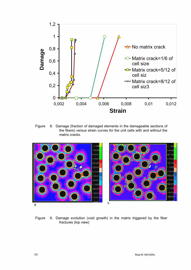
34 Risø-R-1601(EN)
Figure 8. Damage (fraction of damaged elements in the damageable sections of the fibers) versus strain curves for the unit cells with and without the matrix cracks.
a b
Figure 9. Damage evolution (void growth) in the matrix triggered by the fiber fractures (top view)
0
0,2
0,4
0,6
0,8
1
1,2
0,002 0,004 0,006 0,008 0,01 0,012
Strain
Dam
age No matrix crack
Matrix crack=1/6 ofcell sizeMatrix crack=5/12 ofcell sizMatrix crack=8/12 ofcell siz3

Risø-R-1601(EN) 35
4. Numerical simulations of interface damage and its interaction with matrix cracks and fiber fractures
Let us consider the interaction between all three damage modes in composites: matrix cracks, interface damage and fiber fracture. In order to model the interface damage, the model of interface as a “third layer” was used [25]. The interface layer was assumed to be a homogeneous isotropic material, with Young modulus 273 MPa (i.e., the mean value of the Young moduli of fiber and matrix) and Poisson’s ratio of the matrix. The thickness of the layer was taken 0.2 mm. Following Tursun et al. [27], we chose the maximum principal stress criterion for the interface damage (therefore, assuming rather brittle interface). Two values of the critical stress were taken: 2000 MPa (i.e., strong, but still damageable interface) and 1000 MPa (weak interface). While the interface layer is considered as a homogeneous material in the first approximation, the model can be further improved if the graded material model is used to represent the interface layer, with properties to be determined from the inverse analysis [1].
Unit cells (with 15 fibers and 25% fiber volume content) were generated, and tested (with different strengths of interface layers). The unit cells without matrix cracks as well as with the cracks (notches) of 0.3 (short crack) and 0.58 of the cell size (long crack) were analyzed. The fiber arrangement in the cells with and without matrix cracks was the same.
Figure 11 shows von Mises stress distribution in the fibers and in the interface layer before and after the fiber cracking (the case of the longer matrix crack, and of the strong damageable interface). One can see that the fiber cracking leads to the high stress concentration at the interfaces of the composite in the vicinity of the fiber cracks.
Figure 12 shows the damage (fraction of failed elements) in fibers and in the interface plotted versus the applied strain, for the case of strong and weak interfaces, and the cracked matrix (long crack). In the case of the strong interface, the interface damage growth starts at a higher strain than the fiber cracking, and begins in the vicinity of the fiber cracks. Apparently, the interface damage growth is triggered by the fiber cracking. In the case of the weaker interface, the interface damage is not triggered by the fiber cracking, but precedes the fiber cracking: while in the unit cells with the stronger interfaces the interface damage begins only after the fibers fail (at the strain 0.00543), in the unit cells with weak interfaces the interface damage begins at the strain 0.0026.
Thus, the interface properties influence the bearing capacity and damage resistance of fibers: in the case of the weak fiber/matrix interface, fiber failure begins at much lower applied strains than in the case of the strong interface.
5. Conclusions Computational simulations of the deformation and damage evolution in fiber reinforced composites are presented. New techniques of modeling of fiber fracturing and the interface damage are proposed and employed: the finite element weakening in the layers (sections) of the fibers, randomly placed along the fiber length (for the modeling of fiber cracking), and the element weakening in the interphase layer between the fibers and matrix (for the modeling of the interface damage). Using these new methods and the developed techniques of the automatic generation of 3D

36 Risø-R-1601(EN)
microstructural models of composites, we investigated numerically the effect of the matrix cracks and the interface strength on the fiber failure. It is demonstrated that the interface properties influence the bearing capacity and damage resistance of fibers: in the case of the weak fiber/matrix interface, fiber failure begins at much lower applied strains than in the case of the strong interface.
Figure 10. Von Mises stresses in the interface layer in the vicinity of the cracked fibers.

Risø-R-1601(EN) 37
Figure 11. Von Mises stresses in the unit cell with the matrix crack and the interface layer: before (a) and after (b) the fiber failure
38 Risø-R-1601(EN)
Figure 12. Damage-strain curves for fibers and interface damage for the strong (failure stress 2000 MPa) and weak (failure stress 1000 MPa) interfaces [1]. The unit cell with the longer matrix crack (0.58 of the cell size) is considered.
References:
1. Mishnaevsky Jr. L. (2007) Computational Mesomechanics of Composites, John Wiley and Sons, London (in print)
2. Sørensen, B.F. and Jacobsen, T.K. (1998), Large scale bridging in composites: R-curve and bridging laws. Composites A 29, pp. 1443-1451
3. Sørensen, B.F. and Jacobsen, T.K. (2000), Crack growth in composites - Applicability of R-curves and bridging laws, Plastics, Rubber and Composites, 29, pp. 119-133
4. Sastry, A. M., and S. L. Phoenix (1993) Load redistribution near non-aligned fiber breaks in a 2-D unidirectional composite using break-influence superposition. Materials Science Letters 12, pp.1596-99
5. Landis C. M., Beyerlein I. J. and McMeeking R.M. (2000) Micromechanical simulation of the failure of fiber reinforced composites, J Mechanics and Physics of Solids, Vol. 48, 3, pp. 621-648
6. Beyerlein I.J., and Phoenix S. L.(1996) Stress concentrations around multiple fiber breaks in an elastic matrix with local yielding or debonding using quadratic influence superposition, Journal of the Mechanics and Physics of Solids, Vol. 44, 12, pp. 1997-2039
0
0,05
0,1
0,15
0,2
0,25
0,3
0,35
0,001 0,003 0,005 0,007 0,009Strain
Dam
age
Strong IF, Fiber
Strong IF, IF
Weak IF, Fiber
Weak IF, IF

Risø-R-1601(EN) 39
7. Beyerlein I.J., and Phoenix S. L. (1997) Statistics of fracture for an elastic notched composite lamina containing Weibull fibers— Part I. Features from Monte-Carlo simulation, Engineering Fracture Mechanics, Vol. 57, 2-3, pp. 241-265
8. Xia Z. H. and Curtin W. A. (2001) Multiscale modeling of damage and failure in aluminum-matrix composite, Composites Science and Technology, Vol. 61, 15, pp. 2247-2257
9. Xia Z., Curtin W. A. and Okabe T.(2002) Green's function vs. shear-lag models of damage and failure in fiber composites , Composites Science and Technology, Vol. 62, 10-11, pp. 1279-1288
10. Kun, F., Zapperi, S., and Herrmann, H. J. (2000) Damage in fiber bundle models. European Physical Journal B17, pp. 269-279
11. Raischel, F., Kun, F. and Herrmann, H.J. (2006) Failure process of a bundle of plastic fibers, Physical Review E 73, 066101 -12
12. Marshall D. B., Cox B. N. and Evans A. G. (1985) The mechanics of matrix cracking in brittle-matrix fiber composites, Acta Metall. 33, 2013-2021
13. McCartney L. N., (1987) Mechanics of Matrix Cracking in Brittle-Matrix Fiber-Reinforced Composites,” Proc. R. Soc. London, A, 409,329-50 (1987).
14. Slaughter W. S. (1993) A self-consistent model for multi-fiber crack bridging, Int J Solids and Structures, Vol. 30, 3, pp. 385-398
15. Asp L. E., Berglund L. A. and Talreja R. (1996a) Effects of fiber and interphase on matrix-initiated transverse failure in polymer composites, Composites Science and Technology Vol. 56, 6 , pp. 657-665
16. Vejen N. and Pyrz R. (2002) Transverse crack growth in glass/epoxy composites with exactly positioned long fibres. Part II: numerical, Composites Part B: Engineering, Vol. 33, 4, pp. 279-290
17. Gonzalez, C. and LLorca, J. (2006) Multiscale modeling of fracture in fiber-reinforced composites Acta Materialia, 54, pp. 4171–4181
18. L. Mishnaevsky Jr and S. Schmauder, Continuum Mesomechanical Finite Element Modeling in Materials Development, Applied Mechanics Reviews, Vol. 54, 1, 2001, pp. 49-69.
19. L. Mishnaevsky Jr, Three-dimensional Numerical Testing of Microstructures of Particle Reinforced Composites, Acta Materialia, 2004, Vol. 52/14, pp.4177-4188
20. L. Mishnaevsky Jr, Automatic voxel based generation of 3D microstructural FE models and its application to the damage analysis of composites, Materials Science & Engineering A, Vol. 407, No. 1-2, 2005, pp.11-23
21. L. Mishnaevsky Jr, Functionally gradient metal matrix composites: numerical analysis of the microstructure-strength relationships, Composites Sci. & Technology, 2006, Vol 66/11-12 pp 1873-1887
22. L. Mishnaevsky Jr, Damage and fracture of heterogeneous materials, Balkema, Rotterdam, 1998, 230 pp.
23. L. Mishnaevsky Jr, P. Brøndsted, 3D Micromechanical analysis of mechanisms of the degradation in fiber reinforced composites (in preparation)
24. L. Mishnaevsky Jr., N. Lippmann, S. Schmauder, Computational modeling of crack propagation in real microstructures of steels and virtual testing of artificially designed Materials, Int. J. Fracture, Vol. 120, Nr. 4, 2003, pp. 581-600
25. Downing T. D. , Kumar R. , Cross W. M. , Kjerengtroen L. and Kellar J. J. (2000) Determining the interphase thickness and properties in polymer matrix composites using phase imaging atomic force microscopy and nanoindentation, J. Adhesion Science and Technology, Vol. 14, 14, pp. 1801-1812
26. Huang Y, Petermann J (1996) Interface layers of fiber-reinforced composites with transcrystalline morphology. Polymer Bulletin, 36(4), pp.517-524
27. Tursun G., Weber U., Soppa E. and Schmauder S. (2006) The influence of transition phases on the damage behaviour of an Al/10vol.%SiC composite, Comput Materials Science, Vol. 37, 1-2, pp. 119-133
28. K. Derrien, D. Baptiste, D. Guedra-Degeorges, J. Foulquier, Multiscale modelling of the damaged plastic behaviour of AlSiCp composites. Int. J. Plasticity, Vol. 15, 667-685, 1999
29. Rice, J.R. and Tracey, D.M. (1969) On the ductile enlargement of voids in triaxial stress fields, J. Mechanics and Physics of Solids, 17, pp. 201-217

40 Risø-R-1601(EN)
5 Modeling of fatigue damage evolution on the basis of the kinetic concept of strength
Abstract: On the basis of the kinetic theory of strength, a new approach to the modeling of material degradation in cyclic loading has been suggested. Assuming that not stress changes, but acting stresses cause the damage growth in materials under fatigue conditions, we applied the kinetic theory of strength to model the material degradation. The damage growth per cycle, the effect of the loading frequency on the lifetime and on the stiffness reduction in composites were determined analytically. It has been shown that the number of cycles to failure increases almost linearly and the damage growth per cycle decreases with increasing the loading frequency.
1. Introduction
One of the oldest problems in the fatigue analysis has been the analysis of the interrelations between the loading conditions and the lifetime of materials (number of the cycles to failure) [1-5]. Among the analytical, experimental and statistical approaches, used to investigate this problem, one may list the concepts based on the Wöhler curve and Basquin equation, rain-flow counting, Palmgren-Miner’s rule of damage accumulation, Paris law and different generalizations of the fracture and damage mechanics approaches The main challenge in most of these works was to take into account explicitly the temporal effects in fatigue, which do influence the lifetime of materials [1]. However, many of the underlying concepts and approaches used either do not take into account the temporal effects (as fracture mechanics), or are based on the data analysis and averaging (as Wöhler curves and Paris law) [5]. In particular, the problem of the effect of loading frequency on the damage growth and lifetime of materials can be hardly explained in the framework of the static concepts. As noted by Parsons et al [2], “for different polymers, the crack growth rate (expressed in units of length per number of cycles) may decrease, remain nearly constant, or increase with increasing frequency”. Hertzberg et al. [7] studied the effect of test frequency on polymer fatigue performance, seeking to explain a diminution of fatigue resistance with increasing cyclic frequency in unnotched test samples, and the enhancement of fatigue resistance in many polymers with increasing cyclic frequency in notched samples. As noted by Hertzberg et al. [7], contradictory trends in frequency-sensitive materials properties are responsible for these differences. The relative fatigue behavior reflects “a competition between strain rate and creep effects”, as well as the effect of β transition in polymers [7]. Takemori [8] noted that the conclusions on the frequency effects made on the basis of an analysis of unnotched specimens are not transferable on notched specimens case. Moskala [9] also noted that the fatigue resistance of the untoughened amorphous blend of polycarbonate was not affected by test frequency, whereas the fatigue resistance of the toughened blend increased with increasing frequency. Mandell and Meier [10] studied load frequency effects for cross-ply E-glass/epoxy laminates, carrying out tests with 3 frequencies (0.01, 0.1, and 1 Hz), and observed that the number of cycles increased with increasing load frequency. Saff, and other researchers also considered the effect of frequency on the fatigue behavior [11-13]. These and other results were summarized in [14] as follows: “at low frequency ranges where there is negligible heat dissipation, as the load

Risø-R-1601(EN) 41
frequency increases, cycles to failure increase also. As higher frequency ranges are considered this increase is at a slower rate. When there is excessive heat dissipation, however, a reverse trend can be observed.” One of the ways to analyze the time-dependent effects on the fatigue crack growth is to consider the crack growth rate as a superposition of fatigue and creep components [7, 15]. So, Lee et al. [16] analyzed the damage growth in polymer composite materials on the basis of the fracture mechanics model by Wnuk [15]. Using the transition from fracture to damage mechanics concept, they derived the following formula dD/dN=c1 (σmax
2/D)m+(c2/f) (σmax2/D)n (1)
where c1, c2, m, n – parameters of the material. The interrelations between the static and fatigue failure was considered in several works [25-27]. Miyano and colleagues [25] demonstrated that “the reciprocation law of time and temperature “ is applicable for both the static and fatigue strengths, and that both the fatigue and static fracture modes and the slope of the S-N curves remains the same in the large temperature range. Oh and Yoon [27] derived a formula for the fatigue life using the Zhurkov-type static life equation as well. The purpose of this work is to investigate the effect of the loading history in cyclic loading on the damage evolution and lifetime of materials using the kinetic theory of strength [17-24] and the stepwise representation of the loading variation during the fatigue cycles. As differed from the level crossing approach to the fatigue modeling suggested by Holm and de Mare [28] and applied by Holm, de Mare and colleagues [29, 30], we assume here that not the stress changes, but the acting constant stresses cause damage growth in materials. This assumption has been confirmed experimentally in many tests for static loading [24], and can be therefore used as a basis for the modeling of fatigue. Here only the case of relative low loading frequency ranges is considered, when the dynamic effects as well as the heat dissipation do not play any role. 2. Kinetic model of failure applied to the time-dependent loading Let us consider a specimen under constant tensile stress (Figure 1a). It has been shown in many works (e.g., [1, 23-31]), that the lifetime of a specimen under constant load is an exponential function of applied stress and temperature:
)exp(kT
BAFtσ
−=
(2)
where tF -time-to-fracture, σ- applied stress, a and c - kinetic constants of material, k - Boltzmann constant, T- temperature. This formula has been derived by several authors on the basis of the analysis of the accumulation of broken atomistic bonds whose breakage is caused by thermofluctuational processes [2], or on the basis of the kinetic theory of failure [18, 19]. Zhurkov introduced a kinetic concept of strength of solids, where time to rupture follows an Arrhenius-Eyring law with an energy barrier decreasing with increasing stress, and the driving mechanism for subcritical damaging processes is thermal activation [2]. Some versions of this formula were suggested by Hsiao [22], and Cherepanov [23]. Oliveira [32] further investigated and justified the kinetic model of fracture theoretically. Regel et al. [24] carried out experimental investigations of this interrelation and determined material parameters for this curve. Consider now a more complex case of multi-step loading, shown in Figure 1b. Apparently, a failure of a material is not a step-wise event after a lapse of time, but continuous process of the defect accumulation and degradation at the lower scale
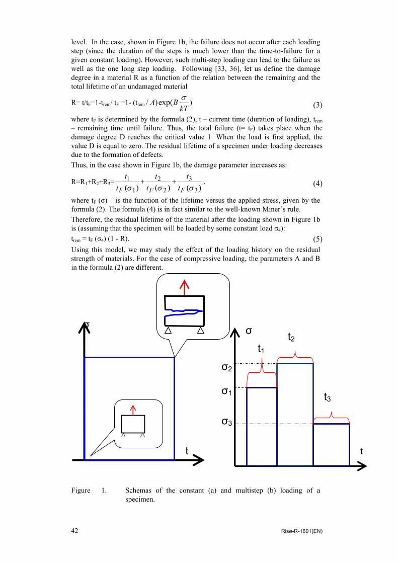
42 Risø-R-1601(EN)
level. In the case, shown in Figure 1b, the failure does not occur after each loading step (since the duration of the steps is much lower than the time-to-failure for a given constant loading). However, such multi-step loading can lead to the failure as well as the one long step loading. Following [33, 36], let us define the damage degree in a material R as a function of the relation between the remaining and the total lifetime of an undamaged material
R= t/tF=1-trem/ tF =1- (trem )exp()/kT
BA σ
(3)
where tF is determined by the formula (2), t – current time (duration of loading), trem – remaining time until failure. Thus, the total failure (t= tF) takes place when the damage degree D reaches the critical value 1. When the load is first applied, the value D is equal to zero. The residual lifetime of a specimen under loading decreases due to the formation of defects. Thus, in the case shown in Figure 1b, the damage parameter increases as:
R=R1+R2+R3= )( 1
1σFt
t+
)( 2
2σFt
t+
)( 3
3σFt
t,
(4)
where tF (σ) – is the function of the lifetime versus the applied stress, given by the formula (2). The formula (4) is in fact similar to the well-known Miner’s rule. Therefore, the residual lifetime of the material after the loading shown in Figure 1b is (assuming that the specimen will be loaded by some constant load σ4): trem = tF (σ4) (1 - R). (5) Using this model, we may study the effect of the loading history on the residual strength of materials. For the case of compressive loading, the parameters A and B in the formula (2) are different.
Figure 1. Schemas of the constant (a) and multistep (b) loading of a
specimen.
t
σ
t
σ
σ1
σ2
σ3
t3
t2 t1

Risø-R-1601(EN) 43
3. Fatigue of materials and frequency effect Now let us consider fatigue of materials, given as cyclic tension-tension loading, shown in Figure 2. By discretizing the loading curve, we can represent it as the multi-step loading, which is in principle similar to that shown in Figure 1b. The model developed in Section 2 is applicable to this type of loading. Consider the effect of the loading frequency on damage evolution in this case. Consider one half-cycle of the curve on Figure 2. We represent the time-dependence of the loading in the form: σ =at, (6) where a=dσ/dt= rate of the loading growth at the half-step. In this case, the stress amplitude is σm=atcycle, where tcycle –one half cycle duration, and the relation between the stress amplitude σm and the loading frequency f is given by formula: f=1/2tcycle=a/2σm (7) Figure 2. Cyclic loading: representing of a half-cycle as a multistep loading
t
σ
σ
t
σ
t

44 Risø-R-1601(EN)
. Discretizing the half-cycle curve into M steps, we determine the damage increase for each i-th step as: Ri= ti/tF(σi)= (ti/A)exp(B σi/kT), (8) where ti= tcycle/M, and is independent on i, σi=aiti. The damage increase as a result of the half-cycle is:
Rc=∑M
iRi =∑
M
i ( tcycle /MA)exp(aBitcycle/kTM).
(9)
Taking into account the formula (7), we obtain the relationship between the damage growth in each cycle Dc and the frequency of loading:
Rc= )2
exp(2
1fMkTaiB
fMA
M
i∑
(10)
One can see from this formula that the damage growth rate is a decreasing function of the loading frequency. Transforming the summation (10) into integration (M→ ∞, ti → dt), we have from (8):
Rc=∑M
iRi =∑
M
i(ti/A)exp(B at/kT)= )
kTaBtexp(1
∫A
=(kT/ABa)exp(aBtcycle/kT),
(11)
and
Rc ∝ )2/exp(1 fkTaBf
. (12)
If, according to the Miner’s rule, we define the amount of cycles to failure as NF=1/2Rc, one may see from this formula that the number of cycles to failure increases with increasing the loading frequency. For instance, if we take A=7,0*106 s (=200 hours), B=5.5 E-29 J/Pa, time to failure tF (at the load 200 MPa) is about 100 hours. For this case, we calculated the dependency of the number of cycles to failure on the frequency of cyclic loading. Figure 3 gives the curves of the damage increase per cycle and the amount of cycles to failure plotted versus frequency of loading. (σm=300 MPa, T=270 K). Using the formulas (10)-(12), we can determine the Wöhler (S-N) curve of the material. Defining the failure condition as 2RcN=1, we obtain:
N= ⎟⎠⎞
⎜⎝⎛−
kTB
kTABf mm σσ exp
(13)
This formula is obtained for the case of the triangular loading wave, shown in Figure 2. For the case of the squared wave, the S-N formula takes the form:
N= ⎟⎠⎞
⎜⎝⎛−
kTBfA mσexp2
(14)
where it is assumed that the duration of each loading is 1/2f. It is of interest that the total time to failure is constant: i.e. for the linear damage accumulation law, the frequency of loading does not affect the total time to failure

Risø-R-1601(EN) 45
0,0E+00
5,0E-07
1,0E-06
1,5E-06
2,0E-06
2,5E-06
3,0E-06
0 2 4 6 8 10 12
Frequency, Hz
Dam
age
per c
ycle
a
0,0E+00
1,0E+06
2,0E+06
3,0E+06
4,0E+06
5,0E+06
0 2 4 6 8 10 12
Frequency, Hz
Am
ount
of c
ycle
s to
failu
re
b
Figure 3. The damage increase per cycle (a) and the amount of cycles to failure (b) plotted versus frequency of loading.
4. Stiffness reduction due to the microcracking and the lifetime of a
material In this paper, we used the definition of the damage degree in the material as a parameter of residual lifetime. One can note here that the damage parameter in the continuum damage mechanics is usually assigned two meanings: first, microcracks density, and second, the closeness of the material to failure. The conditions of failure are formulated usually as an equality between the damage parameter and some critical value (see for example, [37]). Kachanov [38] has formulated two meanings of damage parameter as follows: "reduction of the effective elastic stiffness" and "the extent of progression towards the final fracture". The latter meaning corresponds evidently to the parameter R (relative residual lifetime), defined in the section 2.

46 Risø-R-1601(EN)
Let us now establish relationships between the value R, defined in the section 2, and the damage parameter D, defined via the microcrack density or the deterioration of elastic stiffness. The damage growth law, derived by Lemaitre [37], has a form:
2)1( DC
dtdD
−= , (15)
where C – a function of the stress state and material parameters,
C= jipjipveq
EsHR
,,,,
2)3/2(
2εε
σ&& , s - energy strength of damage (material constant),
H =1, if the accumulated plastic strain reached the damage threshold, and H=0,
otherwise, ν –Poisson’s ratio, vR - triaxiality function,
)²/)(21(33/)1(R eqmv σσν−+ν+= . The Lemaitre’s damage parameter is
defined as the relative reduction of the load bearing section of a specimen, and can be determined as D= 1– Edam/E, where Edam and E – elasticity moduli of undamaged and damaged material. Integrating the equation (15), we derive the following cubic equation:
D3– 3D2+D – ∫Cdt =0, (16)
Taking the value C to be constant (over the loading period, compare Figure 1a), we may substitute t instead of ∫Cdt in this formula.
Solving this cubic equation, we obtain the damage parameter D as a function of loading time: D=1 – (1 – Ct)1/3=1– (1 – CR tF)1/3, (17) Thereduction of relative stiffness at each cycle is therefore: dD/dN=Dc=1 – (1 – C/2f)1/3 (18) Similarly to the results by Lee et al. [16], the increase of damage D in each cycle is the more, the less the frequency of loading. Assuming that if D=1, R=1, the formula (17) is reduced to D=1 – (1 – R)1/3, (19) Using equation (17), we may relate the reduction of the material stiffness due to the microcracking, and the relative reduction of lifetime: Edam=E (1 – CR tF)1/3. (20) Apparently, the stiffness of the material decreases when the remaining lifetime decreases. Figure 4 shows the value of the Lemaitre damage D (relative reduction of the material stiffness) plotted versus R. One can see that while the remaining lifetime is almost proportional to the stiffness of damaged material at the initial stages of the damage evolution, the microcrack density grows at the last stages of destruction with almost no effect on the remaining lifetime. It is of interest to compare the curve on Figure 4 with the results on the damage versus percent of life for fiber reinforced polymer composites [34]. The linear-plateau-linear D-R curve reflects three stages: the multiple fiber cracking (first linear part), crack coupling and delamination growth (plateau) and fracture (the second linear part). In our case, the intensive fracturing of the main bearing elements (fibers) at the initial stage of loading, leading to the quick weakening of
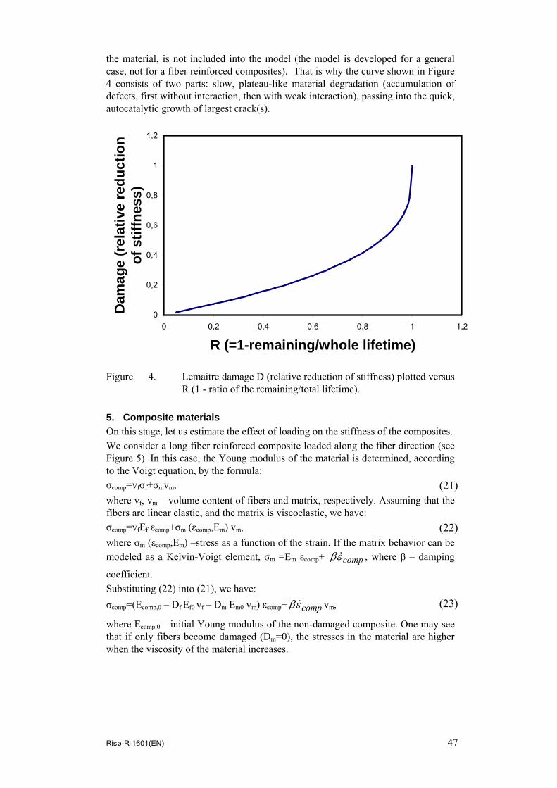
Risø-R-1601(EN) 47
the material, is not included into the model (the model is developed for a general case, not for a fiber reinforced composites). That is why the curve shown in Figure 4 consists of two parts: slow, plateau-like material degradation (accumulation of defects, first without interaction, then with weak interaction), passing into the quick, autocatalytic growth of largest crack(s).
0
0,2
0,4
0,6
0,8
1
1,2
0 0,2 0,4 0,6 0,8 1 1,2
R (=1-remaining/whole lifetime)
Dam
age
(rel
ativ
e re
duct
ion
of s
tiffn
ess)
Figure 4. Lemaitre damage D (relative reduction of stiffness) plotted versus
R (1 - ratio of the remaining/total lifetime). 5. Composite materials On this stage, let us estimate the effect of loading on the stiffness of the composites. We consider a long fiber reinforced composite loaded along the fiber direction (see Figure 5). In this case, the Young modulus of the material is determined, according to the Voigt equation, by the formula: σcomp=vfσf+σmvm, (21) where vf, vm – volume content of fibers and matrix, respectively. Assuming that the fibers are linear elastic, and the matrix is viscoelastic, we have: σcomp=vfEf εcomp+σm (εcomp,Em) vm, (22) where σm (εcomp,Em) –stress as a function of the strain. If the matrix behavior can be modeled as a Kelvin-Voigt element, σm =Em εcomp+ compεβ & , where β – damping
coefficient. Substituting (22) into (21), we have: σcomp=(Ecomp,0 – Df Ef0 vf – Dm Em0 vm) εcomp+ compεβ & vm, (23)
where Ecomp,0 – initial Young modulus of the non-damaged composite. One may see that if only fibers become damaged (Dm=0), the stresses in the material are higher when the viscosity of the material increases.

48 Risø-R-1601(EN)
Figure 5. Fiber reinforced composite: model loading Let us consider the effect of the availability of multiple constituents in the composite on its lifetime. The formula (1) was derived on the basis of both experimental data and probabilistic reasonings (accumulation of broken bonds in the material). Now, we consider the failure of macroelements of the material (fibers and matrix between fibers) as random events as well. As “elements” in this case, fibers and the layers of matrix between the nearest fibers are taken. At this stage of work, only composite with strong interfaces are modeled, thus, only fibers and the section of matrix between fibers can fail. According to the reliability theory, the reliability function (which is defined as a probability that an object does not fail in the time interval (0, t)) is calculated as:
Rel(t)=1–ProbF=exp(-t/tF)= ⎥⎦⎤
⎢⎣⎡− )exp()/(exp
kTBAt σ
,
(24) where ProbF – probability that an object fails in the time interval (0, t). One should note that the formula (24) is derived on the basis of the assumption about exponential probability law for the time-to-failure. While this assumption has some justification (e.g., [36]), other probability laws can be considered here as well. Let us take a matrix between m fibers and the fibers around it, as a unit cell of material. In the case of the cell loaded along the fiber direction, it may be considered as a parallel system made from m +1 elements. For a simplest cell with m=3 fibers and the matrix between them, shown in Figure 6, the reliability function is given by formula: Relsys=1– (1– Relf)m(1–Relm). (25) Assuming that all the elements of the system fail independently (which is not correct, of course, due to the load redistribution after a fiber or the matrix become

Risø-R-1601(EN) 49
damaged [35]), we can determine the mean time to failure of the parallel system under constant loading: tF=(tFf/m)+tFm– (tFf/m +tFm)-1 Apparently, the relation (25) is correct for the constant stress applied during the time t (the case shown in Figure 1a). Consider now again the case shown in Figure 1b. In this case, assuming the exponential reliability function, we have for a single fiber:
Rel(t1+t2+t3) = exp[–)( 1
1σFt
t–
)( 2
2σFt
t–
)( 3
3σFt
t] =exp(–
R1–R2–R3),
(26)
For the case of the fatigue loading (considered in the section 3), the probability that a single fiber does not fail during the half-cycle of fatigue loading, is given by the formula:
Relf(tcycle) = exp(–Rc)=exp[–∑M
i(ti/Af)exp(Bf σf,i/kT)].
(27)
where the index “f” means fiber. Substituting the index “m” for “f”, we can obtain a similar formula for the matrix section between the fibers. Substituting (27) into (25), and taking take into account the formulas (21)-(22) and the load sharing (following the effective stress concept [37]), we can calculate the reliability (probability of non-failure) of a given system. To give an example of the effect of the loading frequency on the reliability of the m fibers-matrix system after many cycles of loading, let us consider the following case. The matrix material, considered above, is reinforced by fibers of another, stronger material (with the parameter Af=2Am, where Am =A=7,0*106 s is equal to the value given above; all other parameters the same). Taking m=4, σm=300 MPa, T=270 K, we can obtain the reliability function after 107 loading cycles of loading as a function of the loading frequency. Figure 7 gives the curve for the considered model case. Figure 6. Parallel system with 3 elements: Matrix with 3 fibers around it
(side view and section)

50 Risø-R-1601(EN)
0
0,2
0,4
0,6
0,8
1
1,2
0 2 4 6 8 10 12 14
Frequency, Hz
Rel
iabi
lity
of th
e sy
stem
Figure 7. Reliability of the system “4 fibers+matrix” after 107 loading
cycles plotted versus the frequency of loading. 6. Comparison with the experimental data Let us compare the results of the kinetic model of fatigue damage with some experimental results. The model, developed above, is applicable to the case when neither dynamic effects nor heat dissipation influence the damage growth in the materials. Thus, we use the experiments by Mandell and Meier [10] to verify this model. Mandell and Meier carried out the tension fatigue tests of plates constructured of eleven unidirectional plies of alternating 0 and 90o. The plates were subject to square and spike loadings. The tests “were run at low frequencies of 1.0, 0.1 and 0.01 Hz to prevent any hysteretic heating.” [10]. As Mandell and Meier noted, “at higher frequencies there is an interaction of heating and mechanical effects, which … was intentionally avoided here”. In [10], both tensile cyclic loading and static experiments for cross-ply E-glass/epoxy laminates are presented. From the static experiments, one can determine the parameters A and B of formula (2). The linear regression formula for the static fatigue test was obtained in the form: S= 369 – 16.5 log t. From this formula, we obtain the following values for A and B for the considered material:
910*139.5=A s; B/kT=0.0606. The S-N curves obtained by Mandell and Meier for different frequencies (0.01, 0.1, and 1 Hz), are presented in Table 1. Table 1. Regression formulas for S-N curves obtained in [10]
Frequency, Hz Regression formulas for the S-N-Curves 1.0 S=405 – 45.0 log N 0.1 S=378 – 40.7 log N
0.01 S=355 – 37.0 log N Figure 8 shows the S-N curve calculated on the basis of the developed model, and its comparison with the experimental data by Mandel and Meier. The deviation from the experimental curve is in the ranges up to 12%. Given the small amount of adjustable

Risø-R-1601(EN) 51
parameters and the approximate type of the model, the difference between the theoretical results and experiments is acceptable.
100
200
300
0 20 40 60 80
N (cycles)
Stre
ss, M
Pa
Experiments: f=0.01 Hz
Theory
Figure 8. Comparison of experiments and theory, for the case of frequency
0.01 Hz. Using the formulas (13) and (14), one can estimate the effect of the wave shape (squared versus triangular) on the N-S curve:
mtria
squar
BkT
NN
σ2
= (28)
Mandell and Meier [10] considered the squared and triangular (spike) shapes of loading weaves, and obtained the following regression formulas for the S-N curves (f=0.1 Hz): Square wave: S=446 – 49.9 log N (29) Spike loading: S=508 – 58.8 log N (30) The ratio between the values of N for squared and triangular loading is 1.09…1.12. Using the formula (28), we can calculate this ratio. Substituting all the values, we have:
=triasquar NN / 1.14…1.16. (31)
Thus, the estimation on the basis of formula (28) gives the results which are very close to the experimental results. 7. Conclusions On the basis of the kinetic theory of strength, a new approach to the modeling of material degradation in cyclic loading has been suggested. Assuming that not stress changes (as in [28-30]), but acting stresses cause the damage growth in materials under cyclic loading, we applied the kinetic theory of strength to model the material degradation in fatigue. The damage growth per cycle, the effects of the loading frequency on the lifetime and on the stiffness reduction in composites were determined analytically. It has been shown that the number of cycles to failure increases almost linearly and the damage growth per cycle decreases with increasing the loading frequency.
52 Risø-R-1601(EN)
References: 1. Suresh, S., Fatigue of Materials, Cambridge University Press, Cambridge, 1998, 704 pp. 2. Palmgren, A. 1924. Lebensdauer von Kugellagern. Verfahreenstechinik, Berlin, 68:
339-341. 3. Miner, M.A. 1945. Cumulative damage in fatigue. Journal of Applied Mechanic 67:
A159-A164. 4. Paris, P. C., M. P. Gomez, and W. E. Anderson. 1961. A rational analytic theory of
fatigue. The Trend in Engineering at the University of Washington 13(1): 9-14. 5. Fatemi, A., Yang, L. 1998. Cumulative fatigue damage and life prediction theories: A
survey of the stat of the art for homogeneous materials. International Journal of Fatigue 20 (1): 9-34
6. M. Parsons, E. V. Stepanov, A. Hiltner, E. Baer, Effect of strain rate on stepwise fatigue and creep slow crack growth in high density polyethylene, J. Materials Science 35 (2000) 1857 – 1866
7. R. W. Hertzberg, J. A. Manson, M. Skibo, Frequency sensitivity of fatigue processes in polymeric solids, Polymer Engineering & Science, Vol. 15 (4), pp. 252-260, 1975
8. M.T. Takemori, Fatigue fracture of polycarbonate, Polymer Engineering & Science, Vol. 22 (15), pp. 937-945, 1992
9. E. Moskala, Effects of mean stress and frequency on fatigue crack propagation in rubber-toughened polycarbonate/copolyester blends, J Applied Polymer Science, Vol. 49, 1 pp. 53-64, 1993
10. Mandell, J.F. and U. Meier, “Effects of Stress Ratio, Frequency, and Loading Time on Tensile Fatigue of Glass-Reinforced Epoxy,” Long-Term Behavior of Composites, ASTM STP 813, T.K. O’Brien, ed., American Society for Testing and Materials, Philadelphia, PA, 1983, pp. 55-77.
11. Saff, C.R., “Effect of Load Frequency and Lay-Up on Fatigue Life of Composites,” Long-Term Behavior of Composites, ASTM STP 813, T.K. O’Brien, ed., American Society for Testing and Materials, Philadelphia, PA, 1983, pp 78-91.
12. Sun C.T. and W.S. Chan, “Frequency Effect on the Fatigue Life of a Laminated Composite,” Composite Materials: Testing and Design (5th Conference), ASTM STP674, American Society for Testing and Materials, Philadelphia, PA, 1979, pp. 418-430.
13. Rotem, A., “Load Frequency Effect on the Fatigue Strength of Isotropic Laminates,” Composites Science and Technology, 46, 1993, pp. 129-138.
14. H. T. Hahn and O. Turkgenc, The Effect of Loading Parameters on Fatigue of Composite Laminates: Part IV Information Systems, 2000, Contract report DOT/FAA/AR-00/48
15. M.P. Wnuk, Quasi-static extension of a tensile crack contained in viscoelastic plastic. solid.” J. Appl. Mech. 41, 234-248 (1974).
16. S. Lee, T. Nguyen, T. Chunang, Model of fatigue damage in strain-rate-sensitive composite materials, J. Mater. Res., Vol. 18, No. 1, pp. 77-80, 2003.
17. Zhurkov, S.N. 1964. Kinetic concept of the strength of solids. Int. J. Fract. Mech. 1 (4): 311-323
18. Yokobori, T. 1968.An interdisciplinary approach to fracture and strength of solids. Groningen: Wolter-Noordhoff
19. Yokobori, T. 1978. The scientific basis of strength and fracture of materials}. Kiev: Naukova Dumka
20. L. Mishnaevsky Jr, Determination for the Time to Fracture of Solids, Int. J. Fracture, Vol.79, No.4, 1996, pp.341-350
21. L. Mishnaevsky Jr, Methods of the Theory of Complex Systems in Modeling of Fracture: a Brief Review, Eng. Fract. Mech., Vol.56, No.1, pp.47-56, 1997
22. Hsiao,C.C. 1989. Kinetic strength of solids. In K.Salama et al (eds). Advanced research fracture: Proc. 7th intern conf fracture, 2913-2918. London: Pergamon.
23. Cherepanov, G.P. 1974. Mechanics of brittle fracture. Moscow: Nauka (in Russian) 24. Regel, V.R., Slutsker, A.I. and Tomashevskiy, I.Ye. 1974. Kinetic nature of strength of
solids. Moscow: Nauka

Risø-R-1601(EN) 53
25. Miyano, Y. McMurray M. Enyama, J., Nakada M. Loading rate and temperature dependenc on flexural fatigue behavior of a satin-woven CFRP laminate, J. Comp. Mater., 28(13), 1994, pp. 538-550
26. S. W. Case, N. Iyengar, and K. L. Reifsnider, Life Prediction Tool for Ceramic Matrix Composites at Elevated Temperatures,” Composite Materials: Fatigue and Fracture, Seventh Volume, ASTM STP 1330, R. B. Bucinell, Ed., 165-178, 1998
27. Oh, H.K. and Yoon, W.G. Derivation and application of a dynamic fatigue life equation. Journal of Materials Processing Technology 49 (3-4): 279-285. 1995.
28. Holm S., de Mare J.: A simple model for fatigue life IEEE Trans. Reliab. 37, 314-322 (1988).
29. Holm S., Josefsson L., de Mare J., Svensson T.: Prediction of fatigue life based on level crossings and a state variable. Fatigue Fract. Eng. Mater. Struct. 18, 1089-1100 (1995).
30. Th. Svensson, Fatigue life prediction in service a statistical approach, Dept of Mathematics,s, Gøteborg, 1996
31. I. Narisawa, M. Ishikawa, H. Ogawa, Delayed yielding of polycarbonate under constant load, Journal of Polymer Science, 16: 8, pp. 1459-1470, 1978
32. F. A. Oliveira, Transition-state analysis for fracture nucleation in polymers: The Lennard-Jones chain, Phys. Rev. B 57, 10576–10582 (1998)
33. L. Mishnaevsky Jr and S. Schmauder, Damage Evolution and Heterogeneity of Materials: Model based on Fuzzy Set Theory, Eng. Fract. Mech., Vol.57, No.6, pp.625-636, 1997
34. K.L. Reifsnider et al., Composite Materials Series: Fatigue of Composites, New York, Elsevier, Vol. 4, 1990
35. Phoenix, S. L., and Beyerlein, I. J., 2000, "Statistical Strength Theory for Fibrous Composite Materials," Comprehensive Composite Materials, A. Kelly, C. Zweben, and T. W. Chou, eds., Vol. 1, Pergamon, pp. 559–639
36. L. Mishnaevsky Jr, Damage and Fracture of Heterogeneous Materials, Balkema, Rotterdam, 1998, 230 pp.
37. Lemaitre, J. 1992. A course on damage mechanics. Berlin: Springer 38. Kachanov, M. 1987. On modeling of anisotropic damage in elastic-brittle materials - A
brief review. In A.S.D.Wang and G.K.Haritos (eds), Damage mechanics in composites: 99-105. New York: ASCE

www.risoe.dk
Risø’s research is aimed at solving concrete problems in the society. Research targets are set through continuous dialogue with business, the political system and researchers. The effects of our research are sustainable energy supply and new technology for the health sector.