
Micromachining of TiNi shape memory alloy by excimer laser ablation
8
Micromachining of TiNi shape memory alloy by excimer laser ablation S T Davies*, E C Harvey, H Jin, J P Hayes and M K Ghantasala *Centre for Nanotechnology and Microengineering School of Engineering, University of Warwick Coventry CV4 7AL, United Kingdom Industrial Research Institute Swinburne (IRIS) 533 –545 Burwood Road Hawthorn, Melbourne 3122, Australia ABSTRACT In this paper we investigate excimer laser micromachining of TiNi shape memory alloy using an image projection system as an alternative to photolithographic patterning. We report on the characteristics of material removal by KrF excimer laser induced ablation at 248 nm and the dependence of material removal rates on laser parameters such as fluence and pulse frequency. Fluences at the workpiece using a 10× projection lens were up to 2.5 J cm -2 with pulse repetition rates up to 100 Hz. Conventional chrome-on-quartz masks were used for pattern transfer. Material removal mechanisms and rates of material removal are compared with those observed during excimer laser micromachining of polymers and ceramics and limitations on achievable lateral and depth resolution explored. Data obtained by a variety of characterisation methods are correlated to assess the effects of laser induced damage. Keywords: Micromachining, shape memory alloy, TiNi, excimer laser ablation. 1. INTRODUCTION Shape memory alloy (SMA) materials are currently the focus of much attention owing to their applicability as micropositioners and microactuators in MEMS technology. In particular, equiatomic TiNi is of interest as a SMA for microsystems applications owing to favourable phase transition temperatures, high work output per unit volume, biocompatibility and so on 1 . Forming of shape memory materials in bulk is well established and relies on processes such as casting, forging, hot and cold rolling and drawing 2 . However, microfabrication and micromachining of SMA materials for miniature devices poses special problems as conventional patterning and forming techniques are difficult to apply. For this reason, several alternative methods have been explored by a number of research groups, including electrolytic photoetching, chemical etching and laser machining. Electrolytic photoetching has the advantage of a high etch rate compared with conventional chemical etching and is capable of producing sheets of SMA with thicknesses comparable with the grain size of around 20 µm. The process results in good surface finish, near-vertical side walls and no degradation in shape memory properties using an electrolyte of 5% sulphuric acid in methanol 3 . Chemical etching has been investigated using a hydrofluoric/nitric acid solution but suffers from problems of nonuniform undercut during etching of annealed TiNi 4 . Laser machining of TiNi has been reported using Nd:YAG (q- switched) lasers, Nd:YAG (diode pumped) lasers and Ti:sapphire pulsed lasers, covering a range of wavelengths from the visible to the infra-red and spanning a wide range of pulse energies, pulse repetition rates and pulse durations 5 . There is advantage in terms of achievable resolution, sidewall perpendicularity and minimising the heat affected zone in working at femto-second pulse durations provided by the Ti-sapphire laser. However, this is achieved at the expense of ablation rate, which is extremely low due to the very small average power. Excimer lasers offer yet further choices of operational parameters to the researcher. Thus the aim of the present work is to explore the benefits and limitations of 248 nm excimer laser ablation as a means of micromachining and micropatterning TiNi shape memory alloys.
Transcript of Micromachining of TiNi shape memory alloy by excimer laser ablation

Micromachining of TiNi shape memory alloyby excimer laser ablation
S T Davies*, E C Harvey, H Jin, J P Hayes and M K Ghantasala
*Centre for Nanotechnology and MicroengineeringSchool of Engineering, University of Warwick
Coventry CV4 7AL, United Kingdom
Industrial Research Institute Swinburne (IRIS)533 –545 Burwood Road
Hawthorn, Melbourne 3122, Australia
ABSTRACT
In this paper we investigate excimer laser micromachining of TiNi shape memory alloy using an image projection system as analternative to photolithographic patterning. We report on the characteristics of material removal by KrF excimer laser inducedablation at 248 nm and the dependence of material removal rates on laser parameters such as fluence and pulse frequency.Fluences at the workpiece using a 10× projection lens were up to 2.5 J cm-2 with pulse repetition rates up to 100 Hz.Conventional chrome-on-quartz masks were used for pattern transfer. Material removal mechanisms and rates of materialremoval are compared with those observed during excimer laser micromachining of polymers and ceramics and limitations onachievable lateral and depth resolution explored. Data obtained by a variety of characterisation methods are correlated to assessthe effects of laser induced damage.
Keywords: Micromachining, shape memory alloy, TiNi, excimer laser ablation.
1. INTRODUCTION
Shape memory alloy (SMA) materials are currently the focus of much attention owing to their applicability as micropositionersand microactuators in MEMS technology. In particular, equiatomic TiNi is of interest as a SMA for microsystems applicationsowing to favourable phase transition temperatures, high work output per unit volume, biocompatibility and so on1. Forming ofshape memory materials in bulk is well established and relies on processes such as casting, forging, hot and cold rolling anddrawing2. However, microfabrication and micromachining of SMA materials for miniature devices poses special problems asconventional patterning and forming techniques are difficult to apply. For this reason, several alternative methods have beenexplored by a number of research groups, including electrolytic photoetching, chemical etching and laser machining.
Electrolytic photoetching has the advantage of a high etch rate compared with conventional chemical etching and is capable ofproducing sheets of SMA with thicknesses comparable with the grain size of around 20 µm. The process results in good surfacefinish, near-vertical side walls and no degradation in shape memory properties using an electrolyte of 5% sulphuric acid inmethanol3. Chemical etching has been investigated using a hydrofluoric/nitric acid solution but suffers from problems ofnonuniform undercut during etching of annealed TiNi4. Laser machining of TiNi has been reported using Nd:YAG (q-switched) lasers, Nd:YAG (diode pumped) lasers and Ti:sapphire pulsed lasers, covering a range of wavelengths from thevisible to the infra-red and spanning a wide range of pulse energies, pulse repetition rates and pulse durations5. There isadvantage in terms of achievable resolution, sidewall perpendicularity and minimising the heat affected zone in working atfemto-second pulse durations provided by the Ti-sapphire laser. However, this is achieved at the expense of ablation rate,which is extremely low due to the very small average power. Excimer lasers offer yet further choices of operational parametersto the researcher. Thus the aim of the present work is to explore the benefits and limitations of 248 nm excimer laser ablationas a means of micromachining and micropatterning TiNi shape memory alloys.
2. SHAPE MEMORY MATERIALS
Shape memory alloys are a novel class of materials having the property of returning to a predetermined or “remembered” shapewhen heated above a martensitic to austenitic transformation temperature6. In the low temperature martensitic state, thematerial is ductile with a very low yield strength and so can be deformed easily into a new shape. This shape is retained belowthe transformation temperature but, on heating, the alloy will return to its original shape. The origin of this unique behaviour isdue to the martensitic transformation, which is a diffusionless solid-state phase transformation resulting in twinning throughshear deformation, as opposed to deformation by movement of dislocations. Stresses applied to the alloy in the martensitic stateresult in the growth of one twin variant at the expense of others. On subsequent heating to a temperature above the austenitefinish temperature, each variant reverts to the parent phase in the original orientation by the reverse transformation, therebyproducing a physical displacement (or force if the movement is restricted) which is the basis for the use of SMA materials asactuators.
In thin-film form, the most promising candidate for microsystems technology applications is TiNi. The work output per unitvolume is claimed to exceed 107 J m-3, which is one to two orders of magnitude higher than for other methods of realisingmicroactuators based on piezoelectric, magnetic or electrostatic principles7. A drawback in integrating thin-film TiNi devicesinto microfabricated systems has been the requirement for a high temperature annealing step in order that the deposited filmexhibit shape memory behaviour. However, ion beam sputter deposition, as an alternative to conventional magnetron sputterdeposition, has been developed to grow TiNi thin films at low temperature which exhibit the shape memory effect in the as-deposited state8. A further drawback in realising practical devices is thought to be the speed of response. While direct Jouleheating can rapidly raise the temperature to initiate the martensitic to austenitic transition, natural cooling places limits on thespeed of the reverse transformation. Measurements of radiative heat transfer coefficients at millimetre dimensions, though,indicate that scaling to microsystems dimensions would give acceptable speeds of response9. In spite of these perceiveddrawbacks, TiNi thin films have been already exploited in devices such as microvalves10, micropumps11, microgrippers4 andmicroelectrodes12.
3. EXCIMER LASER ABLATION
The use of excimer lasers for photoablation (usually termed simply ablation) of organic polymers has been investigated foraround 25 years and has been extensively reviewed in the literature13,14. Advantages include a high degree of control overmaterial removal, coupled with minimal thermal damage. The low coherence of the excimer laser enables its use in projectionsystems where the entire field is illuminated to achieve high throughput. Absence of speckle guarantees uniformity of exposure,leading to predictable, reproducable, material removal characteristics. Absorption in the material of short (10 - 20 ns), intensepulses of UV radiation results in breaking of atomic bonds and rapid expulsion of fragmented molecular species at ultrasonicvelocities. The interaction depth for the laser pulses in the material is determined by the optical absorption coefficient and is ofthe order of tens of nanometres for most polymers, ceramics and metals. The effect of beam energy density (fluence) onmaterial removal is wavelength dependent but small enough for the interaction depth to be the dominant factor. Hence the layerof material removed per pulse can be of this order, thus allowing precise control of the micromachining process. The energy ofthe incident pulse (at least in the case of polymer materials) is removed by the ablated fragments with consequently little or nothermal damage to the target.
In laser ablation of ceramics, the processes of spallation, exfoliation and thermal shock effects are thought to play a significantrole. For instance, excimer laser ablation of diamond is understood to occur by initial graphitisation of the irradiated areafollowed by sublimation and ablation of the thermally insulating graphite film15. Diamond has high absorption in the UV, thusallowing the graphitisation process to proceed at relatively low energy density within a localised interaction volume.Nevertheless, fluences of around 5-6 J cm-2 are required to give comparable ablation depths per pulse to those achievable inpolymers and metals at fluences ~ 1 J cm-2. The ablation of metal targets is a strongly thermal process and dependent on thethickness of the target relative to the thermal diffusion length in the metal. Ablation of thin (50 nm) metal films has beendemonstrated with high resolution patterning and good quality edge definition16. Under these conditions the metal film isexplosively removed due to the absorption and thermalisation of the photon energy, resulting in a sharp temperature rise at themetal-substrate interface. Outgassing of the substrate then leads to explosive fragmentation of the metal film in a near moltenstate. Threshold fluences for ablation of thin Ni films were observed to be lower (~ 0.1 J cm-2 for a film thickness of 500 nm)than those predicted on the basis of melting and evaporation mechanisms. Ablation thresholds for thin metallic films quoted byother workers17 include Ni (≤ 1.0 J cm-2), Au (~ 0.35 J cm-2), Al (≤ 0.9 J cm-2) and Cu (≤ 0.7 J cm-2). For films whosethicknesses are much larger than the thermal diffusion length, higher threshold fluences are to be expected as rapid diffusion of
heat from the irradiated area will require a higher power input. Under these conditions, the metal is melted and evaporated,resulting in a heat affected zone (HAZ) and condensation and redeposition of metal droplets in the vicinity of the ablated area.
4. EXPERIMENTAL
4.1. Excimer laser system
The excimer laser was operated at 248 nm, in constant energy mode, with energy set at either 300 mJ or 400 mJ. Pulseduration was in the range 10 - 25 ns (assumed typically to be ~ 15 ns) with pulse repetition frequency (PRF) programmable upto 100 Hz. The beam delivery optics included a double array (6×6) homogeniser, illuminating a 10×10 mm2 field, and havingapproximately 5% RMS deviation in intensity uniformity in the plane of the mask. The beam exposing the selected pattern onthe mask was directed through a 10× projection lens to give a 1×1 mm2 field in the plane of the sample. The projection lens hada NA of 0.3, giving a diffraction limited resolution of 0.8 µm. The fluence at the sample position was measured as a function ofattenuator setting using a calibrated energy meter. Conventional chrome-on-glass photomasks were used, having patterns ofgeometrical features appropriate for the laser micromachining experiments. For the majority of experiments, a mask patternconsisting of an array of square and circlar apertures positioned within a 10×10 mm2 field was selected to allow simultaneousexposure of features over a wide dimensional scale. When imaged through a 10x projection lens, the mask pattern producedfeatures with dimensions ranging from 10x10 µm2 to 250x250 µm2 of square section and features with diameters ranging from50 to 250 µm of round section in the plane of the sample. A step-and-repeat procedure was then used to replicate this pattern astwo dimensional 5x5 arrays having, either, (a) number of laser shots increasing as a function of increasing fluence at constantPRF, or (b) number of laser shots increasing as a function of increasing PRF at constant fluence. Envelopes of interest withinthese parameter spaces were explored and the relationships between the ablation characteristics of TiNi at various dimensionalscales and geometries with number of shots, PRF and fluence were investigated.
4.2. SMA samples
TiNi samples were obtained in the form of as-rolled strip and thin free-standing foils. The strip was commercially available andsupplied by Nitinol Devices and Components Inc. The strip, of thickness 150 µm, was cut into 25×25 mm2 squares andmounted using double-sided adhesive conducting carbon tape onto standard glass microscope slides for ease of handling. Thethin film samples were deposited by conventional RF sputter deposition using an alloy target at IEMN, Lille, France18. Thesesamples were subsequently separated from the substrates and supplied as free-standing foils of 3 µm thickness. Prior to excimerlaser ablation the thin foil samples were mounted in an identical way to the rolled strip samples.
5. LASER ABLATION OF TiNi
5.1. Ablation thresholds
Ablation thresholds for TiNi at 248 nm were investigated by exposing two-dimensional arrays of sites, spanning a wide rangeof shots, fluences and PRFs. Arrays were then identified within which the ablation threshold was crossed, as determined byoptical and confocal laser scanning microscopy. Typical results are shown in Tables 2 and 3 where the ablation threshold iscrossed for a specific combination of shots, fluence and PRF. Heavily shaded cells signify that ablation was observed at a givensite, while lightly shaded cells signify that no ablation was observed. In these instances, the total number of shots was increasedin geometric progression from 8 to 128, the fluence was varied from 0.45 to 2.25 J cm-2 and the PRFs were 25 Hz and 100 Hzrespectively. The data indicate that the ablation threshold is a function of all three parameters. For the examples shown, at 25Hz, the ablation threshold was found to be < 32 shots for a beam fluence of 1.25 J cm-2; at 100 Hz, the ablation threshold wasfound to be < 32 shots for a beam fluence of 0.45 J cm-2.

Table 2. Dependence of ablation threshold for TiNi Table 3. Dependence of ablation threshold for TiNion beam fluence and laser shots @ 25 Hz. on beam fluence and laser shots @ 100 Hz.
Number of shots @ 25 Hz Number of shots @ 100 HzFluence(J cm-2)
8 16 32 64 128 Fluence(J cm-2)
8 16 32 64 128
2.25 2.252.2 2.21.85 1.851.25 1.250.45 0.45
5.2. Ablation rates
Depths of ablated features were measured using an Olympus OLS1100 confocal laser scanning microscope (CLSM) andrelated to the cumulative number of laser firing shots, beam fluence and PRF. The average depth of ablation as a function ofnumber of shots at a fluence of 1.9 J cm-2 and PRF of 50 Hz is plotted in Fig.1.
Ablated depth versus number of shots
0
5
10
15
20
100 200 300 400 500 600 700 800
Number of shots @ 50 Hz
Ab
late
d d
epth
(m
icro
ns)
70 micron squares
Ablated depth versus number of shots
0
5
10
15
20
25
30
35
16 32 64 128 256 512
Number of shots
Ab
late
d d
epth
(m
icro
ns)
100 Hz; 2.25 J cm-2
25 Hz; 2.25 J cm-2
Fig.1. Depth of ablation as a function of laser shots Fig.2. Depth of abaltion as a function of laser shots at a PRF of 50 Hz. at PRFs of 25 and 100 Hz.
The data of Fig.1 relate to square section features with dimensions of 70×70 µm2. The solid line is the least-squares fit to thedata points. Error bars on these points (and on points in other similar plots) are standard deviations calculated from the scatterof individual measurements and in the case of Fig.1 suggest that the data is consistent with a linear relationship between ablateddepth and number of shots. The slope of the graph would correspond to an ablation rate of around 0.02 µm/shot if the materialremoval were assumed to be uniform. In addition, the data shows that excimer laser ablation is capable of acceptable materialremoval rates. Throughput is an important consideration for any method of micromachining or patterning, of microstructures.In contrast with serial writing techniques such as focused ion beam micromachining, which have a volumetric material removalrate of ~ 1 µm3 s-1, the average volumetric material removal rate observed here is > 4000 µm3 s-1. However, ablation of largevolumes is usually accompanied by significant trenching at the foot of sidewalls, increased slope angle of sidewalls andevolution of features with uneven and irregular bases. Fig.2. shows the effect of PRF on depth of abalation. Ablated depth asfunction of number of shots is plotted for PRFs of 25 Hz and 100 Hz at a fluence of 2.25 J cm-2 for square section featureswith dimensions of 70×70 µm2. Typically the ratio of ablated depths at the two PRFs for a given number of shots is 3 : 1.
5.3. Scaling and fluence effects
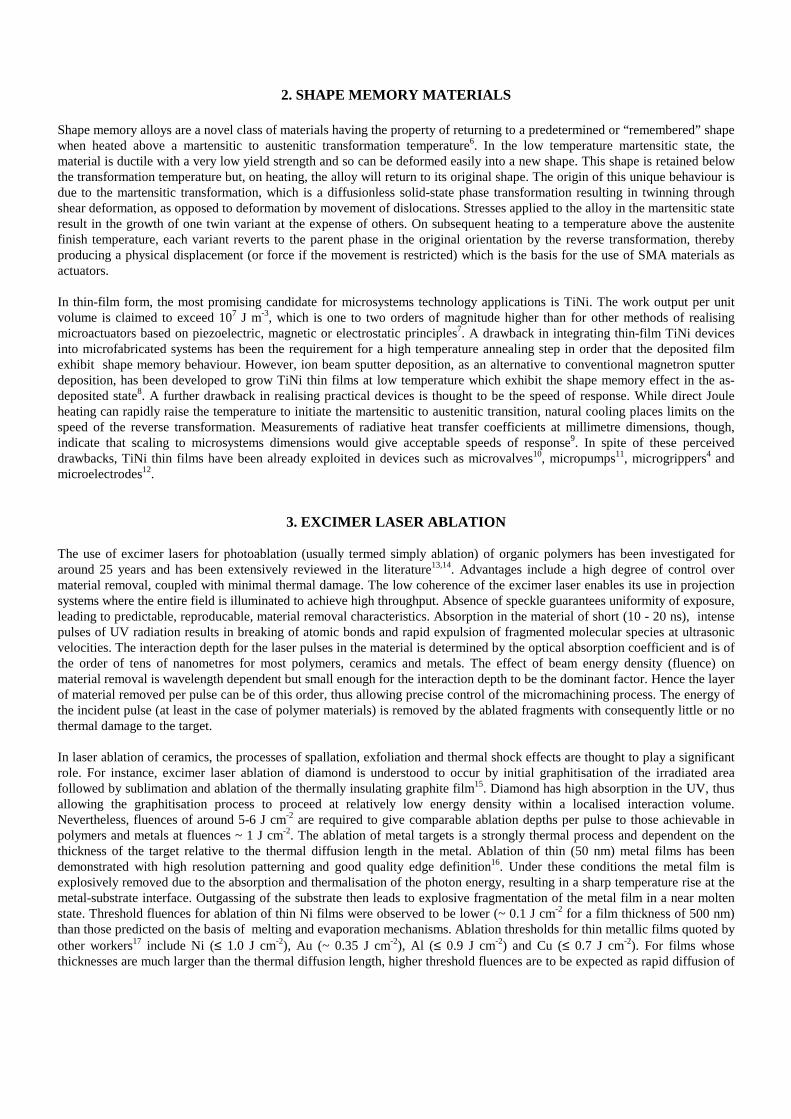
Depth of ablation as a function of feature size for square section features ranging from 10×10 µm2 to 100×100 µm2 was alsoinvestigated for a range of PRFs at fixed number of shots. Data for a fixed shot number of 256 and PRFs of 25 and 100 Hz areshown in Fig.3. A significant peak in ablation rate occurs at 60×60 µm2 for a PRF of 100 Hz. In contrast, no pronounced peakis seen for a PRF of 25 Hz although the data may be consistent with a smaller, broader, peak at 50×50 µm2. At both extremesof feature size, within the statistical uncertainties, there was no difference in depth of ablation over the range of PRFsinvestigated.
Ablated depth versus feature size
0
5
10
15
20
25
30
10 20 30 40 50 60 70 80 90 100
Feature size (microns)
Ab
late
d d
epth
(m
icro
ns)
256 shots 100 Hz256 shots 25 Hz
Ablated depth versus fluence
0
5
10
15
20
25
1.2 1.3 1.4 1.5 1.6 1.7 1.8 1.9 2 2.1 2.2 2.3
Fluence (J cm-2)
Ab
late
d d
epth
(m
icro
ns)
25 Hz; 256 shots; 60x60 um100 Hz; 256 shots; 60x60 um
Fig.3. Depth of ablation as a function of feature scale Fig.4. Depth of ablation as a function of fluence for PRF’s of 25 and 100 Hz. for PRF’s of 25 and 100 Hz.
Ablation depths as a function of fluence were measured for a range of feature dimensions and PRFs at fixed number of shots.The results for 60×60 µm2 square section features are shown in Fig.4 for a total of 256 shots. For comparison, both sets of datapoints have been fitted by a second-order polynomial although the statistical significance of the 100 Hz data suggests a sharprise in ablation rate for fluences > 2.2 J cm-2 which is in marked contrast to the 25 Hz data.
5.4. Ablation of thin foils
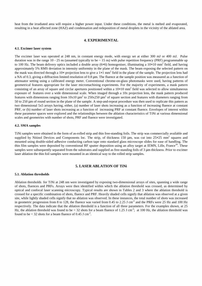
Laser ablation studies of TiNi in the form of thin free-standing foils focused on determining acceptable operating envelopes forthrough-foil penetration and investigating morphological effects of the micromachining process. Typical observations duringablation of through holes are shown in Fig.5. The area irradiated on the sample is of diameter 50 µm, and the sequence ofCLSM images show the evolution after 100, 200, 300 and 500 shots at 25 Hz. Progressive thinning of the material proceedsuntil penetration occurs, whereupon a small aperture is formed. Molten metal around the circumference of the aperture ispulled by surface tension forces into a hole of approximately circular geometry, which then grows in diameter with successivelaser shots. Resolidified molten metal is observed around the periphery which indicates a radially outward flow of material.The hole diameter increases until it approaches (but never reaches) the diameter of the irradiated area. A concentric region isobserved, assumed to be the HAZ, which has a raised profile of several microns in height compared with flat surroundingareas. The width of the zone is typically 5 µm. Some redeposition of molten metal is observed beyond the HAZ. However,volumes of redeposited material are small compared with the total volume of metal ablated.
(a) (b) (c) (d)
Fig.5. Laser ablated 50 µm diameter features in TiNi free-standing foil. (a) 100 shots; (b) 200 shots; (c) 300 shots; (d) 500 shots.
Similar results for through holes of square section are shown in Fig.6 and Fig.7. Fig.6 shows a 60×60 µm2 irradiated area after100, 300 and 500 shots at 50 Hz and beam fluence of 1.2 J cm-2. In contrast to the holes of round section, the observationsshow a tendency for foil penetration to result in a highly irregular aperture with very poor conformity to the geometry of theirradiated area. With increasing number of shots, the aperture size increases but remains irregular and rarely grows in area to >50% of the irradiated region. Again, a peripheral zone, assumed to be the HAZ, is observed together with a well-definedregion of resolidified molten metal.

(a) (b) (c)
Fig.6. Laser ablated 60×60 µm2 features in TiNi free-standing foil. (a) 100 shots; (b) 300 shots; (c) 500 shots.
Fig.7 indicates in more detail the mechanism by which through hole formation takes place. It shows the effect of ablating a30×30 µm2 irradiated area after 100, 200 and 500 shots at 50 Hz and a beam fluence of 1.2 J cm-2. As the foil is initiallypenetrated a through hole of circular section approximately 10 µm in diameter is formed, but becomes increasingly irregular asit grows in size with subsequent additional laser shots. An irradiated area with circular symmetry allows hole evolution tocontinue with a round section being maintained; an irradiated area with square section results in irregular and unpredictablehole growth.
(a) (b) (c)
Fig.7. Laser ablated 30×30µm2 features in TiNi free-standing foil. (a) 100 shots; (b) 200 shots; (c) 500 shots.
Fig.8. Section of 50 µm width slot. Fig.9. Section of 30 µm width slots.
Trials were also carried out with the object of ablating slots in the free-standing TiNi foil. A mask pattern was selected giving aseries of slot dimensions in the plane of the sample ranging from 10×1000 µm2 to 110×1000 µm2. Fig.8 shows a CLSM imageof a section of a 50µm slot after ablation with 100 shots at 50 Hz and a fluence of 0.25 Jcm-2. Foil penetration has occurredalong the axis of the slot, but in an uncontrolled manner, resulting in a highly irregular aperture. By progressively reducing thenumber of shots, the instant of punch-through and mechanism of penetration was visualised. The process is dependent on PRF,number of shots and slot width. A critical stage is shown in Fig.9 for 30 µm slots. A series of roughly equispaced through-holeshaving near circular section have formed along the axis of the slot. The holes are approximately 10 µm in diameter. Withincreasing number of shots the holes elongate into oval sections, eventually merging to yield a slot of well defined width.

6. ANALYSIS AND DISCUSSION
6.1 Ablation thresholds and rates
As ablation of metals is a thermal process, an important parameter will be power input to the irradiated area. The product of theenergy density (fluence), number of shots and PRF gives the power density, enabling a power density matrix to be plotted forgiven operating parameters as shown in Fig.10. The power density matrix in this case relates to the operating envelopespecified by Table 2. Consideration of ablation thresholds for given fluences in Tables 2 and 3 now reveals that 720 W cm-2
< ablation threshold < 1000 W cm-2 and that the ablation threshold follows a contour of constant power density in Fig.10. Theablation rates infered from Fig.1 and Fig.2 can also be reconciled with the power density matrix. At fixed fluence and PRF, thepower density increases linearly with the number of shots thus predicting that ablated depth will also increase linearly.Furthermore, if the PRF increases in a given ratio, power density increases in the same ratio. For PRFs of 100 and 25 Hz theratio is 4 : 1, in good agreement with the observed ablated depth ratio of 3 : 1 in Fig.2.
6.2. Ablation depth, fluence and irradiated area
Power density considerations would predict that depth of ablation increases linearly with fluence. This assumption is notinconsistent with the data of Fig.4 for a PRF of 25 Hz. A linear fit may also be plausible to the 100 Hz data for fluences ≤ 2.2 Jcm-2. However, above this fluence, a step increase in ablated depth is indicative of a different physical mechanism of materialremoval and suggests a transition from melting to evaporation. Such a transition may also explain the peak of Fig.3. Atintermediate dimensions and high PRF, irradiated areas will receive increasing total power input compared with smallerfeatures. Moreover, as feature size increases further, more sidewall area is available to remove heat by conduction. Only in theintermediate regime is the effective power density high enough for evaporation to dominate the material removal process,thus leading to a peak in ablation rate.
816
3264
128
2.25
1.8
0.45
0
1000
2000
3000
4000
5000
6000
7000
8000
Po
wer
per
un
it a
rea
(Wcm
-2)
num be r o f shots
flu
ence
(J
cm-2
)
P ow e r de nsity m a trix @ 25 Hz
7000-8000
6000-7000
5000-6000
4000-5000
3000-4000
2000-3000
1000-2000
0-1000
Fig.10. Power density matrix @ 25 Hz.
6.3. Influence of microstructure
An examination of the microstructure of the sputter-deposited TiNi foils reveals elongated grains of typical length ~50 µm andwidth ~10 µm. The evolution of round section holes with characteristic dimension of around 10 µm is therefore to be expectedduring the ablation process as regions within a grain having locally preferential optical absorption become molten ahead ofneighbouring regions. Alternate grains also show evidence of preferential ablation, indicative of a lower melting point for aparticular orientation. This being the case, the shape and size of the irradiated area then becomes critical in influencing thenumbers and evolution of these precursor through hole structures. The nucleation of holes in irradiated areas much greater thanthe typical grain area will be influenced mainly by surface tension effects; the nucleation of holes in narrow slots will beinfluenced mainly by grain width.

7. CONCLUSIONS
Excimer laser ablation of TiNi shape memory alloys at 248 nm has been investigated and quantitative results on ablationthresholds and ablation rates reported. Ablation thresholds are interpreted in terms of power density delivered by the excimerlaser beam. Ablation rates are in broad agreement with those quoted in the literature for excimer laser ablation of thin metallicfilms. Significant effects attributable to pulse repetition frequency are observed. A qualitative description of excimer lasermicromachining of thin free-standing foils of TiNi is given and the model related to observations of the microstructure of thematerial.
ACKNOWLEDGEMENTS
We thank Dave Niedermeier, Nitinol Devices and Components Inc, for support and gratefully acknowledge the outstandingtechnical backup provided by Martin Lloyd-Diviny and Steve Hunter of Olympus Australia Pty Ltd.
REFERENCES
1. P Krulevitch, A P Lee, P B Ramsey, J C Trevino, J Hamilton and M A Northrup, “Thin film shape memory alloymicroactuators”, J.Microelectromechanical Systems, 5, 270-282 (1996).
2. Y Suzuki, “Fabrication of shape memory alloys” in Shape Memory Materials, K.Otsuka and C.M.Wayman (eds),pp133-148, Cambridge University Press, Cambridge, 1998.
3. M Kohl, K D Skrobanek, C Goh and D M Allen, "Mechanical characterisation of shape memory micromaterials",Proc.SPIE Vol.2880, 108-118 (1996).
4. J J Gill, D T Chang, L A Momoda and G P Carman, “Manufacturing issues of thin film NiTi microwrapper”, Sensorsand Actuators, A93, 148-156 (2001).
5. H Haferkamp, S Paschko and M Goede, “New laser machining processes for shape memory alloys”, Proc SPIE 4234,94-101 (2001).
6. C M Jackson, H J Wagner and R J Wasilewski, “55-Nitinol - the alloy with a memory : its physical metallurgy,properties, and applications”, NASA Report SP 5110 (1972).
7. A D Johnson, "Vacuum-deposited TiNi shape memory film : characterization and applications in microdevices",J.Micromech.Microeng., 1, 34-41 (1991).
8. K Tsuchiya and S T Davies, “Fabrication of TiNi shape memory alloy microactuators by ion beam sputterdeposition”, Nanotechnology, 9, 67-71 (1998).
9. S T Davies and K Tsuchiya, “Growth and characterisation of shape memory alloy thin films for micropositioning andmicroactuation”, Proc. SPIE 3511, 174-182 (1998).
10. M Kohl, D Dittman, E Quandt, B Winzek, “Thin film shape memory microvalves with adjustable operationtemperature”, Sensors and Actuators, 83, 214-219 (2000).
11. E Makino, T Mitsuya and T Shibata, “Micromachining of TiNi shape memory thin film for fabrication ofmicropump”, Sensors and Actuators, 79, 251-259 (2000).
12. S Takeuchi and I Shimoyama, “A three-dimensional shape memory alloy microelectrode with clipping structure forinsect neural recording”, J.Microelectromechanical Systems, 9, 24-31 (2000).
13. R Srinivasan, “Ablation of polymers and biological tissue by ultraviolet lasers”, Science, 234, 559-565 (1986).14. R Srinivasan and B Braren, “Ultraviolet laser ablation of organic polymers”, Chem.Rev., 89, 1303-1316 (1989).15. C P Cristensen, “Micromachining of diamond substrates with waveguide excimer lasers”, Proc. SPIE 2062, Lasers as
tools for manufacturing, 14-21 (1994).16. P H Key, P E Dyer and R D Greenough, “Excimer laser patterning and etching of metals”, In ‘Emerging technologies
for in situ processing’, D J Ehrlich and V T Nguyen (eds), Martinus Nijhoff, 105-112 (1988).17. E Hunger, H Pietsch, S Petzoldt and E Matthias, “Multishot laser ablation of polymer and metal films at 248 nm”,
Appl.Surf.Sci., 54, 227-231 (1992).18. Institut d’Electronique et de Microelectronique du Nord, F-59652 Villeneuve d’Ascq, CEDEX -FRANCE.


![Phototherapy, Photochemotherapy, and Excimer Laser Therapy ... · Excimer Laser Therapy Office-based targeted excimer laser therapy (i.e., 308 nanometers [nm]) is considered medically](https://static.fdocuments.in/doc/165x107/5f14ea18414c5a02c231f9fa/phototherapy-photochemotherapy-and-excimer-laser-therapy-excimer-laser-therapy.jpg)