MicroLogix 1400 Programmable Controllers - Stavebstaveb.ch/downloads/1766-um001_-en-p.pdfUser...
418
MicroLogix 1400 Programmable Controllers Bulletin 1766 Controllers and 1762 Expansion I/O User Manual
Transcript of MicroLogix 1400 Programmable Controllers - Stavebstaveb.ch/downloads/1766-um001_-en-p.pdfUser...
MicroLogix 1400 Programmable ControllersBulletin 1766 Controllers and 1762 Expansion I/O
User Manual
Publication 1766-UM001F-EN-P - March 2011
Important User Information Solid state equipment has operational characteristics differing from those of electromechanical equipment. Safety Guidelines for the Application, Installation and Maintenance of Solid State Controls (publication SGI-1.1 available from your local Rockwell Automation sales office or online at http://literature.rockwellautomation.com) describes some important differences between solid state equipment and hard-wired electromechanical devices. Because of this difference, and also because of the wide variety of uses for solid state equipment, all persons responsible for applying this equipment must satisfy themselves that each intended application of this equipment is acceptable.
In no event will Rockwell Automation, Inc. be responsible or liable for indirect or consequential damages resulting from the use or application of this equipment.
The examples and diagrams in this manual are included solely for illustrative purposes. Because of the many variables and requirements associated with any particular installation, Rockwell Automation, Inc. cannot assume responsibility or liability for actual use based on the examples and diagrams.
No patent liability is assumed by Rockwell Automation, Inc. with respect to use of information, circuits, equipment, or software described in this manual.
Reproduction of the contents of this manual, in whole or in part, without written permission of Rockwell Automation, Inc., is prohibited.
Throughout this manual, when necessary, we use notes to make you aware of safety considerations.
Rockwell Automation, Allen-Bradley, SLC 5/02, SLC 5/03, PLC-5, MicroLogix, SLC 500, RSLogix, RSLinx, RSLogix 500, RSLogix Micro, and TechConnect are trademarks of Rockwell Automation, Inc.
Trademarks not belonging to Rockwell Automation are property of their respective companies.
WARNINGIdentifies information about practices or circumstances that can cause an explosion in a hazardous environment, which may lead to personal injury or death, property damage, or economic loss.
IMPORTANT Identifies information that is critical for successful application and understanding of the product.
ATTENTION Identifies information about practices or circumstances that can lead to: personal injury or death, property damage, or economic loss. Attentions help you identify a hazard, avoid a hazard, and recognize the consequence.
SHOCK HAZARDLabels may be on or inside the equipment, such as a drive or motor, to alert people that dangerous voltage may be present.
BURN HAZARDLabels may be on or inside the equipment, such as a drive or motor, to alert people that surfaces may reach dangerous temperatures.

Summary of Changes
To help you find new and updated information in this release of the manual, we have included change bars as shown to the right of this paragraph.
1 Publication 1766-UM001F-EN-P - March 2011

Summary of Changes 2
Firmware Revision History Features are added to the controllers through firmware upgrades. See the latest release notes, 1766-RN001, to be sure that your controller’s firmware is at the level you need. Firmware upgrades are not required, except to allow you access to the new features. You can only upgrade firmware within the same series of controller.
Publication 1766-UM001F-EN-P - March 2011
Table of ContentsSummary of Changes Firmware Revision History . . . . . . . . . . . . . . . . . . . . . . . . . . . . . . . . . . . 2Table of Contents Preface
Who Should Use this Manual . . . . . . . . . . . . . . . . . . . . . . . . . . . . . . . . 11Purpose of this Manual . . . . . . . . . . . . . . . . . . . . . . . . . . . . . . . . . . . . . 11
Related Documentation. . . . . . . . . . . . . . . . . . . . . . . . . . . . . . . . . . 12Common Techniques Used in this Manual. . . . . . . . . . . . . . . . . . . . . . 12
Chapter 1Hardware Overview Hardware Features . . . . . . . . . . . . . . . . . . . . . . . . . . . . . . . . . . . . . . . . . 13
Component Descriptions. . . . . . . . . . . . . . . . . . . . . . . . . . . . . . . . . . . . 14MicroLogix 1400 Memory Module and Built-in Real-Time Clock 141762 Expansion I/O . . . . . . . . . . . . . . . . . . . . . . . . . . . . . . . . . . . . 15
Communication Cables . . . . . . . . . . . . . . . . . . . . . . . . . . . . . . . . . . . . . 16Programming . . . . . . . . . . . . . . . . . . . . . . . . . . . . . . . . . . . . . . . . . . . . . 17Communication Options . . . . . . . . . . . . . . . . . . . . . . . . . . . . . . . . . . . . 17
Chapter 2Installing Your Controller Agency Certifications . . . . . . . . . . . . . . . . . . . . . . . . . . . . . . . . . . . . . . . 19
Compliance to European Union Directives . . . . . . . . . . . . . . . . . . . . . 19EMC Directive . . . . . . . . . . . . . . . . . . . . . . . . . . . . . . . . . . . . . . . . . 19Low Voltage Directive. . . . . . . . . . . . . . . . . . . . . . . . . . . . . . . . . . . 20
Installation Considerations . . . . . . . . . . . . . . . . . . . . . . . . . . . . . . . . . . 20Safety Considerations. . . . . . . . . . . . . . . . . . . . . . . . . . . . . . . . . . . . . . . 21
Hazardous Location Considerations. . . . . . . . . . . . . . . . . . . . . . . . 21Disconnecting Main Power . . . . . . . . . . . . . . . . . . . . . . . . . . . . . . . 22Safety Circuits. . . . . . . . . . . . . . . . . . . . . . . . . . . . . . . . . . . . . . . . . . 22Power Distribution . . . . . . . . . . . . . . . . . . . . . . . . . . . . . . . . . . . . . 23Periodic Tests of Master Control Relay Circuit . . . . . . . . . . . . . . . 23
Power Considerations . . . . . . . . . . . . . . . . . . . . . . . . . . . . . . . . . . . . . . 23Isolation Transformers . . . . . . . . . . . . . . . . . . . . . . . . . . . . . . . . . . 23Power Supply Inrush . . . . . . . . . . . . . . . . . . . . . . . . . . . . . . . . . . . . 23Loss of Power Source . . . . . . . . . . . . . . . . . . . . . . . . . . . . . . . . . . . 24Input States on Power Down . . . . . . . . . . . . . . . . . . . . . . . . . . . . . 24Other Types of Line Conditions . . . . . . . . . . . . . . . . . . . . . . . . . . . 24
Preventing Excessive Heat. . . . . . . . . . . . . . . . . . . . . . . . . . . . . . . . . . . 25Master Control Relay . . . . . . . . . . . . . . . . . . . . . . . . . . . . . . . . . . . . . . . 25
Using Emergency-Stop Switches . . . . . . . . . . . . . . . . . . . . . . . . . . 26Schematic (Using IEC Symbols) . . . . . . . . . . . . . . . . . . . . . . . . . . . 27Schematic (Using ANSI/CSA Symbols). . . . . . . . . . . . . . . . . . . . . 28
Installing a Memory Module . . . . . . . . . . . . . . . . . . . . . . . . . . . . . . . . . 29Using the Battery . . . . . . . . . . . . . . . . . . . . . . . . . . . . . . . . . . . . . . . . . . 29
Connecting the Battery Wire Connector . . . . . . . . . . . . . . . . . . . . 31Controller Mounting Dimensions . . . . . . . . . . . . . . . . . . . . . . . . . . . . . 32Controller and Expansion I/O Spacing . . . . . . . . . . . . . . . . . . . . . . . . 32Mounting the Controller . . . . . . . . . . . . . . . . . . . . . . . . . . . . . . . . . . . . 32
DIN Rail Mounting . . . . . . . . . . . . . . . . . . . . . . . . . . . . . . . . . . . . . 34
3 Publication 1766-UM001F-EN-P - March 2011
4 Table of Contents
Panel Mounting . . . . . . . . . . . . . . . . . . . . . . . . . . . . . . . . . . . . . . . . 351762 Expansion I/O Dimensions. . . . . . . . . . . . . . . . . . . . . . . . . . . . . 36Mounting 1762 Expansion I/O . . . . . . . . . . . . . . . . . . . . . . . . . . . . . . 36
DIN Rail Mounting . . . . . . . . . . . . . . . . . . . . . . . . . . . . . . . . . . . . . 36Panel Mounting . . . . . . . . . . . . . . . . . . . . . . . . . . . . . . . . . . . . . . . . 37
Connecting Expansion I/O. . . . . . . . . . . . . . . . . . . . . . . . . . . . . . . . . . 38
Chapter 3Wiring Your Controller Wiring Requirements . . . . . . . . . . . . . . . . . . . . . . . . . . . . . . . . . . . . . . 41
Wiring Recommendation. . . . . . . . . . . . . . . . . . . . . . . . . . . . . . . . . 41Wire without Spade Lugs. . . . . . . . . . . . . . . . . . . . . . . . . . . . . . . . . 42Wire with Spade Lugs . . . . . . . . . . . . . . . . . . . . . . . . . . . . . . . . . . . 42
Using Surge Suppressors . . . . . . . . . . . . . . . . . . . . . . . . . . . . . . . . . . . . 43Recommended Surge Suppressors . . . . . . . . . . . . . . . . . . . . . . . . . 44
Grounding the Controller . . . . . . . . . . . . . . . . . . . . . . . . . . . . . . . . . . . 45Wiring Diagrams . . . . . . . . . . . . . . . . . . . . . . . . . . . . . . . . . . . . . . . . . . 46
Terminal Block Layouts. . . . . . . . . . . . . . . . . . . . . . . . . . . . . . . . . . 46Sinking and Sourcing Wiring Diagrams . . . . . . . . . . . . . . . . . . . . . . . . 50
1766-L32BWA, 1766-L32AWA, 1766-L32BXB, 1766-L32BWAA, 1766-L32AWAA, 1766-L32BXBA Wiring Diagrams . . . . . . . . . . 50
Controller I/O Wiring . . . . . . . . . . . . . . . . . . . . . . . . . . . . . . . . . . . . . . 52Minimizing Electrical Noise . . . . . . . . . . . . . . . . . . . . . . . . . . . . . . 52
Wiring Your Analog Channels. . . . . . . . . . . . . . . . . . . . . . . . . . . . . . . . 53Analog Channel Wiring Guidelines. . . . . . . . . . . . . . . . . . . . . . . . . 54Minimizing Electrical Noise on Analog Channels . . . . . . . . . . . . . 54Grounding Your Analog Cable . . . . . . . . . . . . . . . . . . . . . . . . . . . . 55
Expansion I/O Wiring. . . . . . . . . . . . . . . . . . . . . . . . . . . . . . . . . . . . . . 55Digital Wiring Diagrams . . . . . . . . . . . . . . . . . . . . . . . . . . . . . . . . . 55Analog Wiring . . . . . . . . . . . . . . . . . . . . . . . . . . . . . . . . . . . . . . . . . 63
Chapter 4Communication Connections Supported Communication Protocols. . . . . . . . . . . . . . . . . . . . . . . . . . 71
Default Communication Configuration . . . . . . . . . . . . . . . . . . . . . . . . 72Using the Communications Toggle Functionality . . . . . . . . . . . . . . . . 72
Changing Communication Configuration . . . . . . . . . . . . . . . . . . . 73Connecting to the RS-232 Port . . . . . . . . . . . . . . . . . . . . . . . . . . . . . . . 76
Making a DF1 Point-to-Point Connection. . . . . . . . . . . . . . . . . . . 76Using a Modem . . . . . . . . . . . . . . . . . . . . . . . . . . . . . . . . . . . . . . . . 77Connecting to a DF1 Half-Duplex Network . . . . . . . . . . . . . . . . . 80
Connecting to a RS-485 Network . . . . . . . . . . . . . . . . . . . . . . . . . . . . . 82DH-485 Configuration Parameters. . . . . . . . . . . . . . . . . . . . . . . . . 83Recommended Tools. . . . . . . . . . . . . . . . . . . . . . . . . . . . . . . . . . . . 85DH-485 Communication Cable . . . . . . . . . . . . . . . . . . . . . . . . . . . 85
Publication 1766-UM001F-EN-P - March 2011
Table of Contents 5
Connecting the Communication Cable to the DH-485 Connector . 86Grounding and Terminating the DH-485 Network . . . . . . . . . . . 87
Connecting the AIC+ . . . . . . . . . . . . . . . . . . . . . . . . . . . . . . . . . . . . . . 88Cable Selection Guide . . . . . . . . . . . . . . . . . . . . . . . . . . . . . . . . . . . 90Recommended User-Supplied Components . . . . . . . . . . . . . . . . . 93Safety Considerations . . . . . . . . . . . . . . . . . . . . . . . . . . . . . . . . . . . 94Install and Attach the AIC+ . . . . . . . . . . . . . . . . . . . . . . . . . . . . . . 94Powering the AIC+ . . . . . . . . . . . . . . . . . . . . . . . . . . . . . . . . . . . . . 95
Connecting to DeviceNet . . . . . . . . . . . . . . . . . . . . . . . . . . . . . . . . . . . 96Cable Selection Guide . . . . . . . . . . . . . . . . . . . . . . . . . . . . . . . . . . . 96
Connecting to Ethernet . . . . . . . . . . . . . . . . . . . . . . . . . . . . . . . . . . . . 97Ethernet Connections . . . . . . . . . . . . . . . . . . . . . . . . . . . . . . . . . . . 98
Chapter 5Using the LCD Operating Principles. . . . . . . . . . . . . . . . . . . . . . . . . . . . . . . . . . . . . . . 102
Startup Screen . . . . . . . . . . . . . . . . . . . . . . . . . . . . . . . . . . . . . . . . 103Main Menu and Default Screen . . . . . . . . . . . . . . . . . . . . . . . . . . 105Operating Buttons . . . . . . . . . . . . . . . . . . . . . . . . . . . . . . . . . . . . . 107Using Menus to Choose Values . . . . . . . . . . . . . . . . . . . . . . . . . . 107Selecting Between Menu Items . . . . . . . . . . . . . . . . . . . . . . . . . . . 108Cursor Display . . . . . . . . . . . . . . . . . . . . . . . . . . . . . . . . . . . . . . . . 108Setting Values. . . . . . . . . . . . . . . . . . . . . . . . . . . . . . . . . . . . . . . . . 109
I/O Status. . . . . . . . . . . . . . . . . . . . . . . . . . . . . . . . . . . . . . . . . . . . . . . 109Viewing I/O Status . . . . . . . . . . . . . . . . . . . . . . . . . . . . . . . . . . . . 110
Monitor User Defined Target Files . . . . . . . . . . . . . . . . . . . . . . . . . . . 111Target User Defined File Number (TUF) . . . . . . . . . . . . . . . . . . 111Monitoring a Bit File . . . . . . . . . . . . . . . . . . . . . . . . . . . . . . . . . . . 112Monitoring Integer Files . . . . . . . . . . . . . . . . . . . . . . . . . . . . . . . . 117Monitoring Double Integer files . . . . . . . . . . . . . . . . . . . . . . . . . . 122Monitor Floating point Files . . . . . . . . . . . . . . . . . . . . . . . . . . . . . 128Monitor System Status Files . . . . . . . . . . . . . . . . . . . . . . . . . . . . . 128
Using the Mode Switch . . . . . . . . . . . . . . . . . . . . . . . . . . . . . . . . . . . . 129Controller Modes . . . . . . . . . . . . . . . . . . . . . . . . . . . . . . . . . . . . . . 130Changing Mode Switch Position. . . . . . . . . . . . . . . . . . . . . . . . . . 130
Using a User Defined LCD Screen . . . . . . . . . . . . . . . . . . . . . . . . . . . 132User Defined LCD Screen . . . . . . . . . . . . . . . . . . . . . . . . . . . . . . 133
Configuring Advanced Settings . . . . . . . . . . . . . . . . . . . . . . . . . . . . . . 134Changing Key In Mode . . . . . . . . . . . . . . . . . . . . . . . . . . . . . . . . . . . . 135
Key In Modes. . . . . . . . . . . . . . . . . . . . . . . . . . . . . . . . . . . . . . . . . 135Changing Key In Mode . . . . . . . . . . . . . . . . . . . . . . . . . . . . . . . . . 135
Using Communications Toggle Functionality . . . . . . . . . . . . . . . . . . 137Ethernet Network Configuration . . . . . . . . . . . . . . . . . . . . . . . . . . . . 137
Viewing Ethernet Status . . . . . . . . . . . . . . . . . . . . . . . . . . . . . . . . 137Configuring the IP Address. . . . . . . . . . . . . . . . . . . . . . . . . . . . . . 139
Publication 1766-UM001F-EN-P - March 2011
6 Table of Contents
Configuring the Ethernet Port . . . . . . . . . . . . . . . . . . . . . . . . . . . 143Configuring Ethernet Protocol Setup. . . . . . . . . . . . . . . . . . . . . . 146
Using Trim Pots . . . . . . . . . . . . . . . . . . . . . . . . . . . . . . . . . . . . . . . . . . 148Trim Pot Operation . . . . . . . . . . . . . . . . . . . . . . . . . . . . . . . . . . . . 148Changing Data Value of a Trim Pot . . . . . . . . . . . . . . . . . . . . . . . 149Trim Pot Configuration in LCD Function File . . . . . . . . . . . . . . 150Error Conditions . . . . . . . . . . . . . . . . . . . . . . . . . . . . . . . . . . . . . . 151
Viewing System Information . . . . . . . . . . . . . . . . . . . . . . . . . . . . . . . . 151Viewing Fault Code . . . . . . . . . . . . . . . . . . . . . . . . . . . . . . . . . . . . . . . 152Saving/Loading Communication EEPROM . . . . . . . . . . . . . . . . . . . 154
Saving communication EEPROM . . . . . . . . . . . . . . . . . . . . . . . . 154Loading communication EEPROM . . . . . . . . . . . . . . . . . . . . . . . 156
LCD setup . . . . . . . . . . . . . . . . . . . . . . . . . . . . . . . . . . . . . . . . . . . . . . 156Configuring contrast value . . . . . . . . . . . . . . . . . . . . . . . . . . . . . . 157Configuring the backlight . . . . . . . . . . . . . . . . . . . . . . . . . . . . . . . 158
Chapter 6Using Real-Time Clock and Memory Modules
Real-Time Clock Operation. . . . . . . . . . . . . . . . . . . . . . . . . . . . . . . . . 161Operation at Power-up and Entering a Run or Test Mode. . . . . 161Writing Data to the Real-Time Clock . . . . . . . . . . . . . . . . . . . . . . 161RTC Battery Operation . . . . . . . . . . . . . . . . . . . . . . . . . . . . . . . . . 162
Memory Module Operation. . . . . . . . . . . . . . . . . . . . . . . . . . . . . . . . . 162User Program , User Data, Datalog and Recipe Back-up . . . . . . 163Program Compare . . . . . . . . . . . . . . . . . . . . . . . . . . . . . . . . . . . . . 163Data File Download Protection . . . . . . . . . . . . . . . . . . . . . . . . . . 163Memory Module Write Protection . . . . . . . . . . . . . . . . . . . . . . . . 164Removal/Insertion Under Power . . . . . . . . . . . . . . . . . . . . . . . . . 164Memory Module Information File . . . . . . . . . . . . . . . . . . . . . . . . 164Program /Data Download . . . . . . . . . . . . . . . . . . . . . . . . . . . . . . 164Program /Data Upload . . . . . . . . . . . . . . . . . . . . . . . . . . . . . . . . . 165
Chapter 7Online Editing Directions and Cautions for MicroLogix 1400 Online
Editing User . . . . . . . . . . . . . . . . . . . . . . . . . . . . . . . . . . . . . . . . . . . . . 167A Download is Required Before Starting Online Editing . . . . . . 167
Types of Online Editing . . . . . . . . . . . . . . . . . . . . . . . . . . . . . . . . . . . 168Edit Functions in Runtime Online Editing . . . . . . . . . . . . . . . . . 169Edit Functions in Program Online Editing . . . . . . . . . . . . . . . . . 169
Appendix ASpecifications Specifications for Inputs . . . . . . . . . . . . . . . . . . . . . . . . . . . . . . . . 172
Specifications for Outputs in Hazardous Locations(Class 1, Division 2, Groups A, B, C, D) . . . . . . . . . . . . . . . . . . . 174
Publication 1766-UM001F-EN-P - March 2011
Table of Contents 7
Specifications for Outputs in (Non-Hazardous) Locations only . . 175Working Voltage . . . . . . . . . . . . . . . . . . . . . . . . . . . . . . . . . . . . 178
Expansion I/O Specifications . . . . . . . . . . . . . . . . . . . . . . . . . . . . . . . 179Digital I/O Modules . . . . . . . . . . . . . . . . . . . . . . . . . . . . . . . . . . . 179Analog Modules . . . . . . . . . . . . . . . . . . . . . . . . . . . . . . . . . . . . . . 188
Appendix BReplacement Parts MicroLogix 1400 Replacement Kits . . . . . . . . . . . . . . . . . . . . . . . . . . 197
Lithium Battery (1747-BA) . . . . . . . . . . . . . . . . . . . . . . . . . . . . . . . . . 197Installation . . . . . . . . . . . . . . . . . . . . . . . . . . . . . . . . . . . . . . . . . . . 197Battery Handling . . . . . . . . . . . . . . . . . . . . . . . . . . . . . . . . . . . . . . 199Storage . . . . . . . . . . . . . . . . . . . . . . . . . . . . . . . . . . . . . . . . . . . . . . 199Transportation . . . . . . . . . . . . . . . . . . . . . . . . . . . . . . . . . . . . . . . 199Disposal . . . . . . . . . . . . . . . . . . . . . . . . . . . . . . . . . . . . . . . . . . . . . 201
Appendix CTroubleshooting Your System Understanding the Controller Status Indicators . . . . . . . . . . . . . . . . . 203
Controller Status LED Indicators . . . . . . . . . . . . . . . . . . . . . . . . . 203Status Indicators on the LCD . . . . . . . . . . . . . . . . . . . . . . . . . . . . 204I/O Status Indicators on the LCD . . . . . . . . . . . . . . . . . . . . . . . . 205Normal Operation . . . . . . . . . . . . . . . . . . . . . . . . . . . . . . . . . . . . . 205Error Conditions . . . . . . . . . . . . . . . . . . . . . . . . . . . . . . . . . . . . . . 206
Controller Error Recovery Model . . . . . . . . . . . . . . . . . . . . . . . . . . . . 206Analog Expansion I/O Diagnostics and Troubleshooting . . . . . . . . 208
Module Operation and Channel Operation . . . . . . . . . . . . . . . . . 208Power-up Diagnostics . . . . . . . . . . . . . . . . . . . . . . . . . . . . . . . . . . 208Critical and Non-Critical Errors . . . . . . . . . . . . . . . . . . . . . . . . . . 209Module Error Definition Table. . . . . . . . . . . . . . . . . . . . . . . . . . . 209Error Codes . . . . . . . . . . . . . . . . . . . . . . . . . . . . . . . . . . . . . . . . . . 211
Calling Rockwell Automation for Assistance . . . . . . . . . . . . . . . . . . . 212
Appendix DUsing ControlFLASH to Upgrade Your Operating System
Preparing for Firmware Upgrade . . . . . . . . . . . . . . . . . . . . . . . . . . . . 213Install ControlFLASH Software . . . . . . . . . . . . . . . . . . . . . . . . . . 213Prepare the Controller for Firmware Upgrade . . . . . . . . . . . . . . . 214
Using ControlFLASH for Firmware Upgrade . . . . . . . . . . . . . . . . . . 215ControlFLASH Error Messages . . . . . . . . . . . . . . . . . . . . . . . . . . . . . 225Missing or Corrupt OS state . . . . . . . . . . . . . . . . . . . . . . . . . . . . . . . . 228
Recovering from Missing or Corrupt OS State . . . . . . . . . . . . . . 228
Appendix EConnecting to Networks via RS-232/RS-485 Interface
RS-232 Communication Interface . . . . . . . . . . . . . . . . . . . . . . . . . . . . 231RS-485 Communication Interface . . . . . . . . . . . . . . . . . . . . . . . . . . . . 231
Publication 1766-UM001F-EN-P - March 2011
8 Table of Contents
DF1 Full-Duplex Protocol . . . . . . . . . . . . . . . . . . . . . . . . . . . . . . . . . 231DF1 Half-Duplex Protocol . . . . . . . . . . . . . . . . . . . . . . . . . . . . . . . . . 232
DF1 Half-Duplex Operation. . . . . . . . . . . . . . . . . . . . . . . . . . . . . 232Considerations When Communicating as a DF1 Slave on a Multi-drop Link . . . . . . . . . . . . . . . . . . . . . . . . . . . . . . . . . . . 234Using Modems with MicroLogix Programmable Controllers . . . 234
DH-485 Communication Protocol . . . . . . . . . . . . . . . . . . . . . . . . . . . 235DH-485 Configuration Parameters. . . . . . . . . . . . . . . . . . . . . . . . 236Devices that use the DH-485 Network . . . . . . . . . . . . . . . . . . . . 237Important DH-485 Network Planning Considerations . . . . . . . . 237Example DH-485 Connections. . . . . . . . . . . . . . . . . . . . . . . . . . . 241
Modbus Communication Protocol . . . . . . . . . . . . . . . . . . . . . . . . . . . 243ASCII . . . . . . . . . . . . . . . . . . . . . . . . . . . . . . . . . . . . . . . . . . . . . . . . . . 243Distributed Network Protocol (DNP3) . . . . . . . . . . . . . . . . . . . . . . . 243
Appendix FMicrologix 1400 Distributed Network Protocol (DNP3)
Channel Configuration for DNP3 Slave . . . . . . . . . . . . . . . . . . . . . . . 245Channel 0 and Channel 2 Link Layer Configuration . . . . . . . . . . 247Channel 1 Link Layer Configuration . . . . . . . . . . . . . . . . . . . . . . 248DNP3 Slave Application Layer Configuration . . . . . . . . . . . . . . . 250Channel 0 and Channel 2 Link Layer Configuration Parameters 252Channel 1(Ethernet) Link Layer Configuration Parameters . . . . 255DNP3 Slave Application Layer Configuration Parameters . . . . . 260
DNP3 Slave Application Layer . . . . . . . . . . . . . . . . . . . . . . . . . . . . . . 272Function Codes . . . . . . . . . . . . . . . . . . . . . . . . . . . . . . . . . . . . . . . 273Internal Indications . . . . . . . . . . . . . . . . . . . . . . . . . . . . . . . . . . . . 277
DNP3 Objects and MicroLogix 1400 Data Files . . . . . . . . . . . . . . . . 278DNP3 Data Files . . . . . . . . . . . . . . . . . . . . . . . . . . . . . . . . . . . . . . 281DNP 3 Configuration Files . . . . . . . . . . . . . . . . . . . . . . . . . . . . . . 282DNP3 Binary Input Object . . . . . . . . . . . . . . . . . . . . . . . . . . . . . . 287DNP3 Binary Output Object . . . . . . . . . . . . . . . . . . . . . . . . . . . . 289DNP3 Double Bit Binary Input Object . . . . . . . . . . . . . . . . . . . . 292DNP3 Counter Object . . . . . . . . . . . . . . . . . . . . . . . . . . . . . . . . . 294DNP3 Frozen Counter Object . . . . . . . . . . . . . . . . . . . . . . . . . . . 297DNP3 Analog Input Object . . . . . . . . . . . . . . . . . . . . . . . . . . . . . 299DNP3 Analog Output Object. . . . . . . . . . . . . . . . . . . . . . . . . . . . 303DNP3 BCD Object . . . . . . . . . . . . . . . . . . . . . . . . . . . . . . . . . . . . 305DNP3 Data Set Object . . . . . . . . . . . . . . . . . . . . . . . . . . . . . . . . . 306Object Quality Flags . . . . . . . . . . . . . . . . . . . . . . . . . . . . . . . . . . . 318
DNP3 Device Attribute Object. . . . . . . . . . . . . . . . . . . . . . . . . . . . . . 321Event Reporting . . . . . . . . . . . . . . . . . . . . . . . . . . . . . . . . . . . . . . . . . . 325
Generating Events . . . . . . . . . . . . . . . . . . . . . . . . . . . . . . . . . . . . . 325Control Generating Event. . . . . . . . . . . . . . . . . . . . . . . . . . . . . . . 330Reporting Event By Polled Response. . . . . . . . . . . . . . . . . . . . . . 331Reporting Event By Unsolicited Response . . . . . . . . . . . . . . . . . 332
Publication 1766-UM001F-EN-P - March 2011
Table of Contents 9
Collision Avoidance . . . . . . . . . . . . . . . . . . . . . . . . . . . . . . . . . . . . . . . 334Time Synchronization . . . . . . . . . . . . . . . . . . . . . . . . . . . . . . . . . . . . . 335Download a User Program via DNP3 Network. . . . . . . . . . . . . . . . . 336
Default Directories and Files . . . . . . . . . . . . . . . . . . . . . . . . . . . . 337Generating *.IMG files using RSLogix 500/RSLogix Micro. . . . 337Rules for File Authentication . . . . . . . . . . . . . . . . . . . . . . . . . . . . 339Rules for Downloading a User Program. . . . . . . . . . . . . . . . . . . . 340Rules for Uploading a User Program . . . . . . . . . . . . . . . . . . . . . . 341Rules for Initializing a User Program . . . . . . . . . . . . . . . . . . . . . . 342Rules for uploading Communication Status Files . . . . . . . . . . . . 342Starting and Stopping User Programs (Mode Change) via DNP3 Network . . . . . . . . . . . . . . . . . . . . . . . . . . . . . . . . . . . . . . . . . . . . . 342Initialize User Program . . . . . . . . . . . . . . . . . . . . . . . . . . . . . . . . . 343Start User Program . . . . . . . . . . . . . . . . . . . . . . . . . . . . . . . . . . . . 343Stop User Program . . . . . . . . . . . . . . . . . . . . . . . . . . . . . . . . . . . . 344
Diagnostics . . . . . . . . . . . . . . . . . . . . . . . . . . . . . . . . . . . . . . . . . . . . . . 344Diagnostics for Ethernet Channel (Channel 1) . . . . . . . . . . . . . . 352Diagnostics for Secure Authentication . . . . . . . . . . . . . . . . . . . . . 359
Function Codes . . . . . . . . . . . . . . . . . . . . . . . . . . . . . . . . . . . . . . . . . . 361Implementation Table . . . . . . . . . . . . . . . . . . . . . . . . . . . . . . . . . . . . . 364
Appendix GConnecting to Networks via Ethernet Interface
MicroLogix 1400 Controllers and Ethernet Communication . . . . . . 377MicroLogix 1400 Performance Considerations . . . . . . . . . . . . . . . . . 378MicroLogix 1400 and PC Connections to the Ethernet Network . . . . . . . . . . . . . . . . . . . . . . . . . . . . . . . . . . . . . . . . 379
Ethernet Network Topology. . . . . . . . . . . . . . . . . . . . . . . . . . . . . 379Connecting an Ethernet switch on the Ethernet Network . . . . . 379Cables . . . . . . . . . . . . . . . . . . . . . . . . . . . . . . . . . . . . . . . . . . . . . . . 380
Ethernet Connections . . . . . . . . . . . . . . . . . . . . . . . . . . . . . . . . . . . . . 382Duplicate IP address Detection . . . . . . . . . . . . . . . . . . . . . . . . . . . . . 383Configuring the Ethernet Channel on the MicroLogix 1400. . . . . . . 384Configuration Using RSLogix 500/RSLogix Micro Programming Software . . . . . . . . . . . . . . . . . . . . . . . . . . . . . . . . . . . . . . . . . . . . . . . . 386Configuration Via BOOTP . . . . . . . . . . . . . . . . . . . . . . . . . . . . . . . . . 386
Using the Rockwell BOOTP/DHCP Utility . . . . . . . . . . . . . . . . 388Using a DHCP Server To Configure Your Processor . . . . . . . . . . . . 390Using Subnet Masks and Gateways. . . . . . . . . . . . . . . . . . . . . . . . . . . 390
Manually Configuring Channel 1 for Controllers on Subnets . . . . . . . . . . . . . . . . . . . . . . . . . . . . . . . . . . . . . . . . . . . . . . 391
MicroLogix 1400 Embedded Web Server Capability . . . . . . . . . . . . . 392
Appendix HSystem Loading and Heat Dissipation
System Loading Calculations . . . . . . . . . . . . . . . . . . . . . . . . . . . . . . . 395System Loading Example Calculations . . . . . . . . . . . . . . . . . . . . 396
System Loading Worksheet . . . . . . . . . . . . . . . . . . . . . . . . . . . . . . . . . 397
Publication 1766-UM001F-EN-P - March 2011

10 Table of Contents
Current Loading. . . . . . . . . . . . . . . . . . . . . . . . . . . . . . . . . . . . . . . 398Calculating Heat Dissipation . . . . . . . . . . . . . . . . . . . . . . . . . . . . . . . . 399
Glossary
Index
Publication 1766-UM001F-EN-P - March 2011
Preface
Read this preface to familiarize yourself with the rest of the manual. It provides information concerning:
· who should use this manual
· the purpose of this manual
· related documentation
· conventions used in this manual
· Rockwell Automation support
Who Should Use this Manual
Use this manual if you are responsible for designing, installing, programming, or troubleshooting control systems that use MicroLogix 1400 controllers.
You should have a basic understanding of electrical circuitry and familiarity with relay logic. If you do not, obtain the proper training before using this product.
Purpose of this Manual This manual is a reference guide for MicroLogix 1400 controllers and expansion I/O. It describes the procedures you use to install, wire, and troubleshoot your controller. This manual:
· explains how to install and wire your controllers
· gives you an overview of the MicroLogix 1400 controller system
Refer to publication 1766-RM001, MicroLogix 1400 Programmable Controllers Instruction Set Reference Manual for the MicroLogix 1400 instruction set and for application examples to show the instruction set in use. Refer to your RSLogix 500/RSLogix Micro programming software user documentation for more information on programming your MicroLogix 1400 controller.
11 Publication 1766-UM001F-EN-P - March 2011
12
Related Documentation
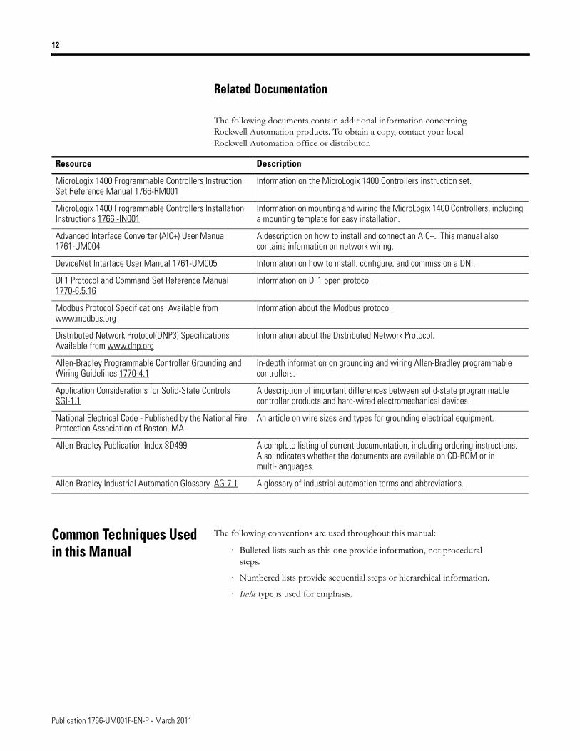
The following documents contain additional information concerning Rockwell Automation products. To obtain a copy, contact your local Rockwell Automation office or distributor.
Common Techniques Used in this Manual
The following conventions are used throughout this manual:
· Bulleted lists such as this one provide information, not procedural steps.
· Numbered lists provide sequential steps or hierarchical information.
· Italic type is used for emphasis.
Resource Description
MicroLogix 1400 Programmable Controllers Instruction Set Reference Manual 1766-RM001
Information on the MicroLogix 1400 Controllers instruction set.
MicroLogix 1400 Programmable Controllers Installation Instructions 1766 -IN001
Information on mounting and wiring the MicroLogix 1400 Controllers, including a mounting template for easy installation.
Advanced Interface Converter (AIC+) User Manual 1761-UM004
A description on how to install and connect an AIC+. This manual also contains information on network wiring.
DeviceNet Interface User Manual 1761-UM005 Information on how to install, configure, and commission a DNI.
DF1 Protocol and Command Set Reference Manual 1770-6.5.16
Information on DF1 open protocol.
Modbus Protocol Specifications Available from www.modbus.org
Information about the Modbus protocol.
Distributed Network Protocol(DNP3) Specifications Available from www.dnp.org
Information about the Distributed Network Protocol.
Allen-Bradley Programmable Controller Grounding and Wiring Guidelines 1770-4.1
In-depth information on grounding and wiring Allen-Bradley programmable controllers.
Application Considerations for Solid-State Controls SGI-1.1
A description of important differences between solid-state programmable controller products and hard-wired electromechanical devices.
National Electrical Code - Published by the National Fire Protection Association of Boston, MA.
An article on wire sizes and types for grounding electrical equipment.
Allen-Bradley Publication Index SD499 A complete listing of current documentation, including ordering instructions. Also indicates whether the documents are available on CD-ROM or in multi-languages.
Allen-Bradley Industrial Automation Glossary AG-7.1 A glossary of industrial automation terms and abbreviations.
Publication 1766-UM001F-EN-P - March 2011
Chapter 1
Hardware Overview
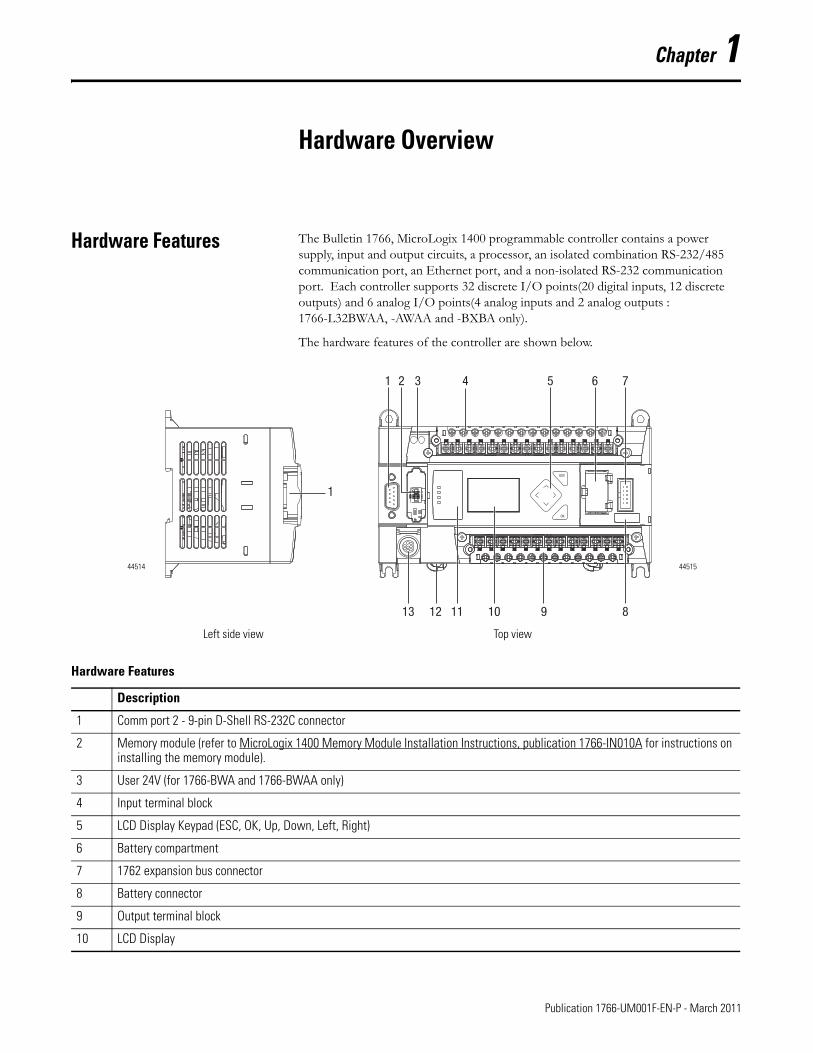
Hardware Features The Bulletin 1766, MicroLogix 1400 programmable controller contains a power supply, input and output circuits, a processor, an isolated combination RS-232/485 communication port, an Ethernet port, and a non-isolated RS-232 communication port. Each controller supports 32 discrete I/O points(20 digital inputs, 12 discrete outputs) and 6 analog I/O points(4 analog inputs and 2 analog outputs : 1766-L32BWAA, -AWAA and -BXBA only).
The hardware features of the controller are shown below.
Hardware Features
Description
1 Comm port 2 - 9-pin D-Shell RS-232C connector
2 Memory module (refer to MicroLogix 1400 Memory Module Installation Instructions, publication 1766-IN010A for instructions on installing the memory module).
3 User 24V (for 1766-BWA and 1766-BWAA only)
4 Input terminal block
5 LCD Display Keypad (ESC, OK, Up, Down, Left, Right)
6 Battery compartment
7 1762 expansion bus connector
8 Battery connector
9 Output terminal block
10 LCD Display
1
ESC
OK
2 5 6 7
89101113 12
43
1
4451544514
Left side view Top view
13 Publication 1766-UM001F-EN-P - March 2011
14 Hardware Overview
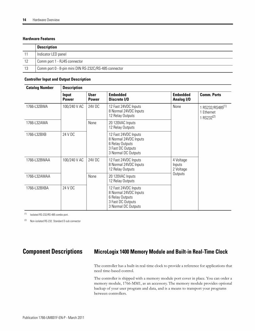
Component Descriptions MicroLogix 1400 Memory Module and Built-in Real-Time Clock
The controller has a built-in real-time clock to provide a reference for applications that need time-based control.
The controller is shipped with a memory module port cover in place. You can order a memory module, 1766-MM1, as an accessory. The memory module provides optional backup of your user program and data, and is a means to transport your programs between controllers.
11 Indicator LED panel
12 Comm port 1 - RJ45 connector
13 Comm port 0 - 8-pin mini DIN RS-232C/RS-485 connector
Controller Input and Output Description
Catalog Number Description
Input Power
User Power
Embedded Discrete I/O
Embedded Analog I/O
Comm. Ports
1766-L32BWA 100/240 V AC 24V DC 12 Fast 24VDC Inputs8 Normal 24VDC Inputs12 Relay Outputs
None 1 RS232/RS485(1) 1 Ethernet1 RS232(2)
1766-L32AWA None 20 120VAC Inputs12 Relay Outputs
1766-L32BXB 24 V DC 12 Fast 24VDC Inputs8 Normal 24VDC Inputs6 Relay Outputs3 Fast DC Outputs3 Normal DC Outputs
1766-L32BWAA 100/240 V AC 24V DC 12 Fast 24VDC Inputs8 Normal 24VDC Inputs12 Relay Outputs
4 Voltage Inputs2 Voltage Outputs
1766-L32AWAA None 20 120VAC Inputs12 Relay Outputs
1766-L32BXBA 24 V DC 12 Fast 24VDC Inputs8 Normal 24VDC Inputs6 Relay Outputs3 Fast DC Outputs3 Normal DC Outputs
(1) Isolated RS-232/RS-485 combo port.
(2) Non-isolated RS-232. Standard D-sub connector
Hardware Features
Description
Publication 1766-UM001F-EN-P - March 2011
Hardware Overview 15
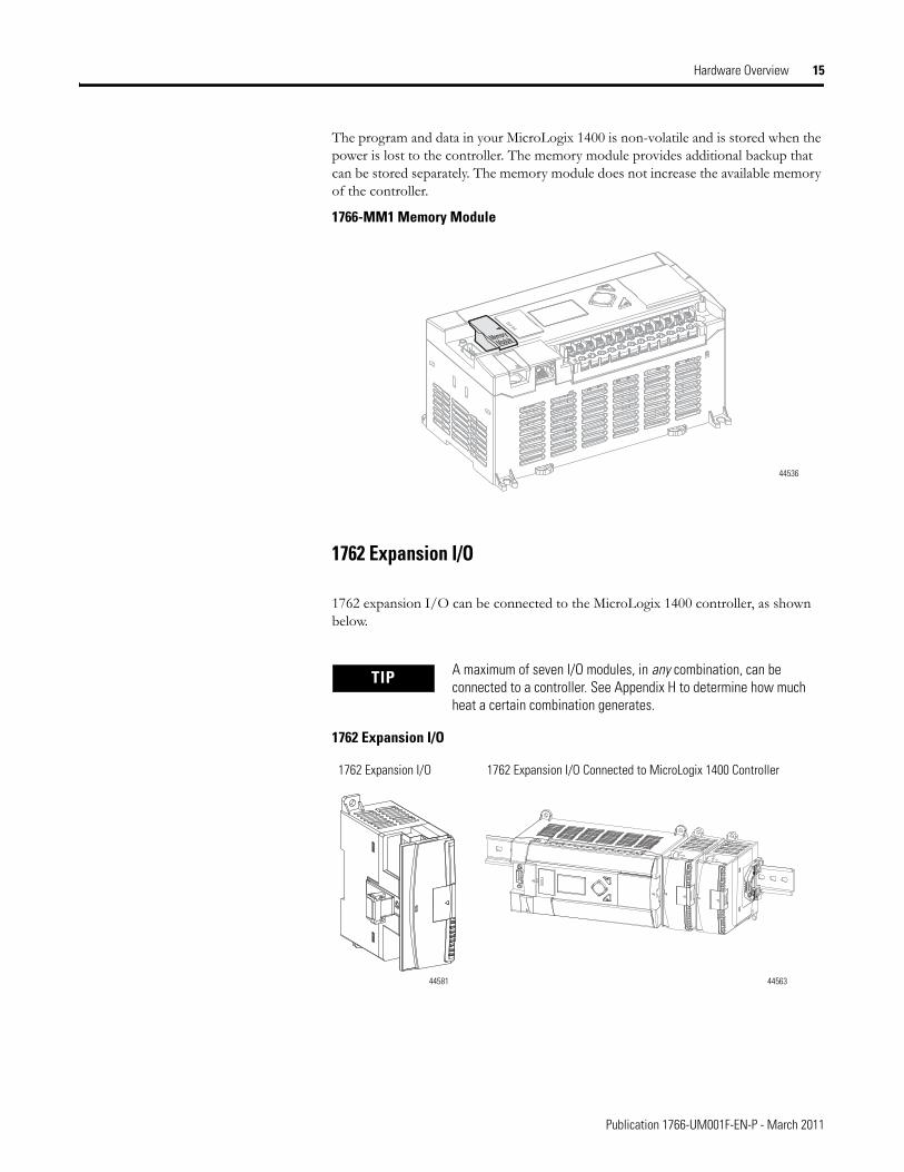
The program and data in your MicroLogix 1400 is non-volatile and is stored when the power is lost to the controller. The memory module provides additional backup that can be stored separately. The memory module does not increase the available memory of the controller.
1766-MM1 Memory Module
1762 Expansion I/O
1762 expansion I/O can be connected to the MicroLogix 1400 controller, as shown below.
1762 Expansion I/O
TIP A maximum of seven I/O modules, in any combination, can be connected to a controller. See Appendix H to determine how much heat a certain combination generates.
ModuleMemory
44536
1762 Expansion I/O 1762 Expansion I/O Connected to MicroLogix 1400 Controller
4456344581
Publication 1766-UM001F-EN-P - March 2011
16 Hardware Overview
Communication Cables Use only the following communication cables with the MicroLogix 1400 controllers. These cables are required for Class I Div. 2 applications.
• 1761-CBL-AM00 Series C or later
• 1761-CBL-AP00 Series C or later
• 1761-CBL-PM02 Series C or later
• 1761-CBL-HM02 Series C or later
• 2707-NC9 Series C or later
• 1763-NC01 Series A or later
• 1747-CP3 Series A or later
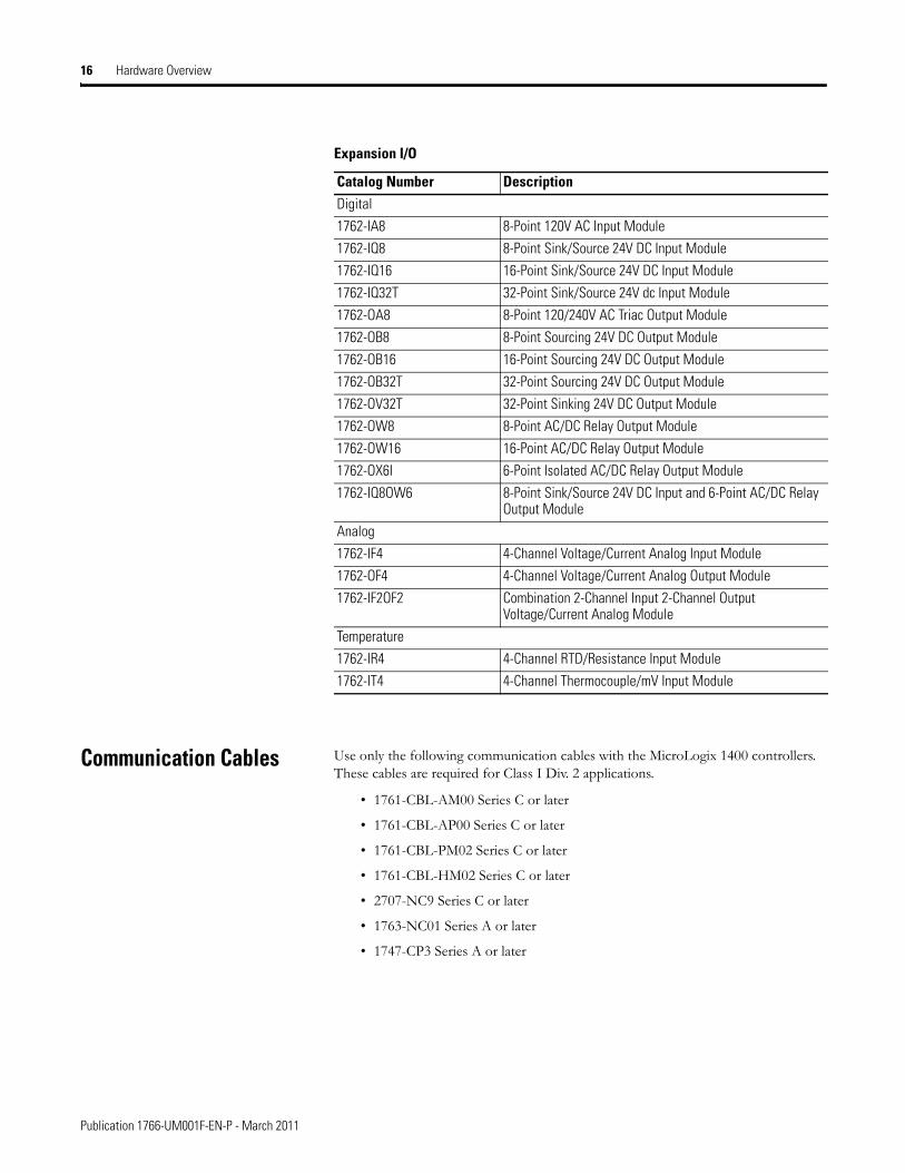
Expansion I/O
Catalog Number DescriptionDigital
1762-IA8 8-Point 120V AC Input Module
1762-IQ8 8-Point Sink/Source 24V DC Input Module
1762-IQ16 16-Point Sink/Source 24V DC Input Module
1762-IQ32T 32-Point Sink/Source 24V dc Input Module
1762-OA8 8-Point 120/240V AC Triac Output Module
1762-OB8 8-Point Sourcing 24V DC Output Module
1762-OB16 16-Point Sourcing 24V DC Output Module
1762-OB32T 32-Point Sourcing 24V DC Output Module
1762-OV32T 32-Point Sinking 24V DC Output Module
1762-OW8 8-Point AC/DC Relay Output Module
1762-OW16 16-Point AC/DC Relay Output Module
1762-OX6I 6-Point Isolated AC/DC Relay Output Module
1762-IQ8OW6 8-Point Sink/Source 24V DC Input and 6-Point AC/DC Relay Output Module
Analog
1762-IF4 4-Channel Voltage/Current Analog Input Module
1762-OF4 4-Channel Voltage/Current Analog Output Module
1762-IF2OF2 Combination 2-Channel Input 2-Channel Output Voltage/Current Analog Module
Temperature
1762-IR4 4-Channel RTD/Resistance Input Module
1762-IT4 4-Channel Thermocouple/mV Input Module
Publication 1766-UM001F-EN-P - March 2011
Hardware Overview 17
Programming Programming the MicroLogix 1400 controller is done using RSLogix 500/RSLogix Micro, Revision 8.10.00 or later for Series A controllers and 8.30.00 or later for Series B controllers. Communication cables for programming are available separately from the controller and software.
Communication Options The MicroLogix 1400 controllers provide three communications ports, an isolated combination RS-232/485 communication port (Channel 0), an Ethernet port (Channel 1) and a non-isolated RS-232 communication port (Channel 2).
The Channel 0 and Channel 2 ports on the MicroLogix 1400 can be connected to the following:
• operator interfaces, personal computers, etc. using DF1 Full Duplex point-to-point
• a DH-485 network
• a DF1 Radio Modem network
• a DF1 half-duplex network as an RTU Master or RTU Slave
• a Modbus network as an RTU Master or RTU Slave
• an ASCII network
• a DeviceNet network as a slave or peer using a DeviceNet Interface (catalog number 1761-NET-DNI)
• an Ethernet network using the Ethernet Interface module (catalog number 1761-NET-ENI, or 1761-NET-ENIW)
• a DNP3 network as a Slave
When connecting to RS-485 network using DH-485, DF1 Half-Duplex Master/Slave, Modbus RTU Master/Slave or DNP3 Slave protocols, the MicroLogix 1400 can be connected directly via Channel 0 without an Advanced Interface Converter, catalog number 1761-NET-AIC. The Channel 0 combo port provides both RS-232 and RS-485 isolated connections. The appropriate electrical interface is selected through your choice of communication cable. The existing MicroLogix 1761 communication cables provide an interface to the RS-232 drivers. The 1763-NC01 cable provides an interface to the RS-485 drivers.
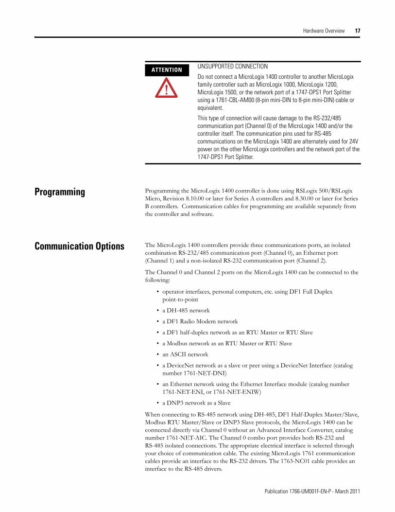
ATTENTION UNSUPPORTED CONNECTION
Do not connect a MicroLogix 1400 controller to another MicroLogix family controller such as MicroLogix 1000, MicroLogix 1200, MicroLogix 1500, or the network port of a 1747-DPS1 Port Splitter using a 1761-CBL-AM00 (8-pin mini-DIN to 8-pin mini-DIN) cable or equivalent.
This type of connection will cause damage to the RS-232/485 communication port (Channel 0) of the MicroLogix 1400 and/or the controller itself. The communication pins used for RS-485 communications on the MicroLogix 1400 are alternately used for 24V power on the other MicroLogix controllers and the network port of the 1747-DPS1 Port Splitter.
Publication 1766-UM001F-EN-P - March 2011

18 Hardware Overview
The controller may also be connected to serial devices, such as bar code readers, weigh scales, serial printers, and other intelligent devices, using ASCII. See Default Communication Configuration on page 72 for the configuration settings for Channel 0. MicroLogix 1400 can be connected directly to RS-485 network via channel 0, using ASCII.
The MicroLogix 1400 supports EtherNet/IP communication via the Ethernet communication Channel 1. In addition, either Modbus TCP or DNP3 over IP can be enabled for Channel 1. You can connect your controller to a local area network that provides communication between various devices at 10 Mbps or 100 Mbps. This port supports CIP explicit messaging (message exchange) only. The controller cannot be used for CIP implicit messaging (real-time I/O messaging). The controller also includes an embedded web server which allows viewing of not only module information, TCP/IP configuration, and diagnostic information, but also includes the data table memory map and data table monitor screen using a standard web browser.
See Chapter 4 for more information on connecting to the available communication options.
Publication 1766-UM001F-EN-P - March 2011
Chapter 2
Installing Your Controller
This chapter shows you how to install your controller. The only tools you require are a flat or Phillips head screwdriver and drill. Topics include:
• agency certifications
• compliance to European Union Directives
• installation considerations
• safety considerations
• power considerations
• preventing excessive heat
• master control relay
• installing a memory module
• using the battery
• controller mounting dimensions
• controller and expansion I/O spacing
• mounting the controller
• mounting 1762 expansion I/O
• connecting 1762 expansion I/O
Agency Certifications • UL Listed Industrial Control Equipment for use in Class I, Division 2, Hazardous Locations, Groups A, B, C, D
• CE marked for all applicable directives
• C-Tick marked for all applicable acts
• C-UL Listed Industrial Control Equipment for use in Canada
Compliance to European Union Directives
This product has the CE mark and is approved for installation within the European Union and EEA regions. It has been designed and tested to meet the following directives.
EMC Directive
This product is tested to meet Council Directive 2004/108/EC Electromagnetic Compatibility (EMC) and the following standards, in whole or in part, documented in a technical construction file:
19 Publication 1766-UM001F-EN-P - March 2011
20 Installing Your Controller
• EN 61131-2; Programmable Controllers (Clause 8, Zone A & B)
• EN 61131-2; Programmable Controllers (Clause 11)
• EN 61000-6-4EMC - Part 6-4: Generic Standards - Emission Standard for Industrial Environments
• EN 61000-6-2EMC - Part 6-2: Generic Standards - Immunity for Industrial Environments
This product is intended for use in an industrial environment.
Low Voltage Directive
This product is tested to meet Council Directive 2006/95/ECLow Voltage, by applying the safety requirements of EN 61131-2 Programmable Controllers, Part 2 - Equipment Requirements and Tests.
For specific information required by EN 61131-2, see the appropriate sections in this publication, as well as the following Allen-Bradley publications:
• Industrial Automation Wiring and Grounding Guidelines for Noise Immunity, publication 1770-4.1
• Guidelines for Handling Lithium Batteries, publication AG-5.4
• Automation Systems Catalog, publication B115
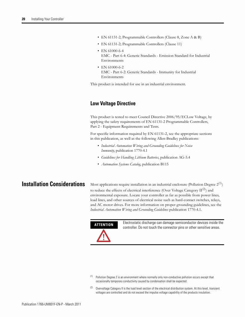
Installation Considerations Most applications require installation in an industrial enclosure (Pollution Degree 2(1))
to reduce the effects of electrical interference (Over Voltage Category II(2)) and environmental exposure. Locate your controller as far as possible from power lines, load lines, and other sources of electrical noise such as hard-contact switches, relays, and AC motor drives. For more information on proper grounding guidelines, see the Industrial Automation Wiring and Grounding Guidelines publication 1770-4.1.
(1) Pollution Degree 2 is an environment where normally only non-conductive pollution occurs except that occasionally temporary conductivity caused by condensation shall be expected.
(2) Overvoltage Category II is the load level section of the electrical distribution system. At this level, transient voltages are controlled and do not exceed the impulse voltage capability of the products insulation.
ATTENTION Electrostatic discharge can damage semiconductor devices inside the controller. Do not touch the connector pins or other sensitive areas.
Publication 1766-UM001F-EN-P - March 2011
Installing Your Controller 21
Safety Considerations Safety considerations are an important element of proper system installation. Actively thinking about the safety of yourself and others, as well as the condition of your equipment, is of primary importance. We recommend reviewing the following safety considerations.
Hazardous Location Considerations
This equipment is suitable for use in Class I, Division 2, Groups A, B, C, D or non-hazardous locations only. The following WARNING statement applies to use in hazardous locations.
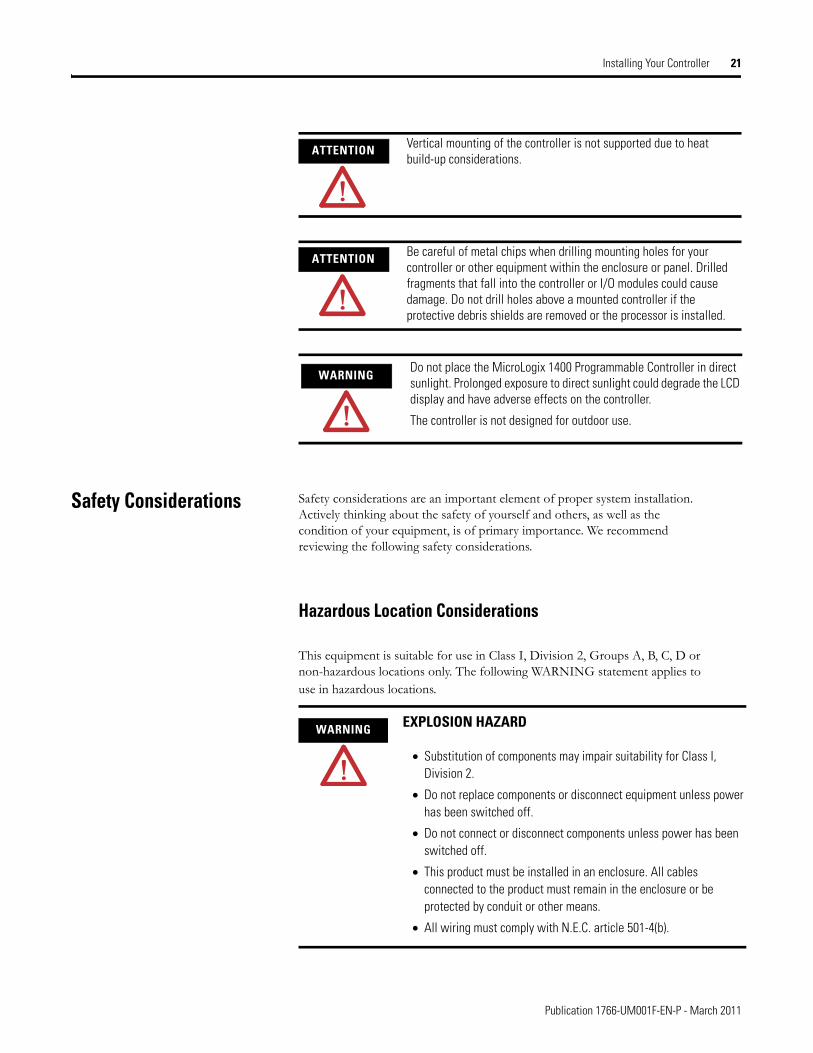
ATTENTION Vertical mounting of the controller is not supported due to heat build-up considerations.
ATTENTION Be careful of metal chips when drilling mounting holes for your controller or other equipment within the enclosure or panel. Drilled fragments that fall into the controller or I/O modules could cause damage. Do not drill holes above a mounted controller if the protective debris shields are removed or the processor is installed.
WARNINGDo not place the MicroLogix 1400 Programmable Controller in direct sunlight. Prolonged exposure to direct sunlight could degrade the LCD display and have adverse effects on the controller.
The controller is not designed for outdoor use.
WARNING EXPLOSION HAZARD
• Substitution of components may impair suitability for Class I, Division 2.
• Do not replace components or disconnect equipment unless power has been switched off.
• Do not connect or disconnect components unless power has been switched off.
• This product must be installed in an enclosure. All cables connected to the product must remain in the enclosure or be protected by conduit or other means.
• All wiring must comply with N.E.C. article 501-4(b).
Publication 1766-UM001F-EN-P - March 2011
22 Installing Your Controller
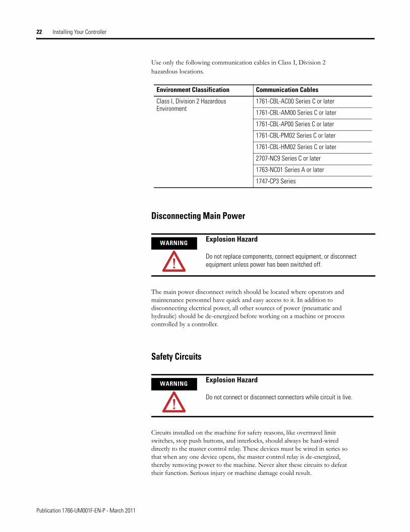
Use only the following communication cables in Class I, Division 2 hazardous locations.
Disconnecting Main Power
The main power disconnect switch should be located where operators and maintenance personnel have quick and easy access to it. In addition to disconnecting electrical power, all other sources of power (pneumatic and hydraulic) should be de-energized before working on a machine or process controlled by a controller.
Safety Circuits
Circuits installed on the machine for safety reasons, like overtravel limit switches, stop push buttons, and interlocks, should always be hard-wired directly to the master control relay. These devices must be wired in series so that when any one device opens, the master control relay is de-energized, thereby removing power to the machine. Never alter these circuits to defeat their function. Serious injury or machine damage could result.
Environment Classification Communication Cables
Class I, Division 2 Hazardous Environment
1761-CBL-AC00 Series C or later
1761-CBL-AM00 Series C or later
1761-CBL-AP00 Series C or later
1761-CBL-PM02 Series C or later
1761-CBL-HM02 Series C or later
2707-NC9 Series C or later
1763-NC01 Series A or later
1747-CP3 Series
WARNING Explosion Hazard
Do not replace components, connect equipment, or disconnect equipment unless power has been switched off.
WARNING Explosion Hazard
Do not connect or disconnect connectors while circuit is live.
Publication 1766-UM001F-EN-P - March 2011
Installing Your Controller 23
Power Distribution
There are some points about power distribution that you should know:
• The master control relay must be able to inhibit all machine motion by removing power to the machine I/O devices when the relay is de-energized. It is recommended that the controller remain powered even when the master control relay is de-energized.
• If you are using a DC power supply, interrupt the load side rather than the AC line power. This avoids the additional delay of power supply turn-off. The DC power supply should be powered directly from the fused secondary of the transformer. Power to the DC input and output circuits should be connected through a set of master control relay contacts.
Periodic Tests of Master Control Relay Circuit
Any part can fail, including the switches in a master control relay circuit. The failure of one of these switches would most likely cause an open circuit, which would be a safe power-off failure. However, if one of these switches shorts out, it no longer provides any safety protection. These switches should be tested periodically to assure they will stop machine motion when needed.
Power Considerations The following explains power considerations for the micro controllers.
Isolation Transformers
You may want to use an isolation transformer in the AC line to the controller. This type of transformer provides isolation from your power distribution system to reduce the electrical noise that enters the controller and is often used as a step-down transformer to reduce line voltage. Any transformer used with the controller must have a sufficient power rating for its load. The power rating is expressed in volt-amperes (VA).
Power Supply Inrush
During power-up, the MicroLogix 1400 power supply allows a brief inrush current to charge internal capacitors. Many power lines and control transformers can supply inrush current for a brief time. If the power source cannot supply this inrush current, the source voltage may sag momentarily.
Publication 1766-UM001F-EN-P - March 2011
24 Installing Your Controller
The only effect of limited inrush current and voltage sag on the MicroLogix 1400 is that the power supply capacitors charge more slowly. However, the effect of a voltage sag on other equipment should be considered. For example, a deep voltage sag may reset a computer connected to the same power source. The following considerations determine whether the power source must be required to supply high inrush current:
• The power-up sequence of devices in a system.
• The amount of the power source voltage sag if the inrush current cannot be supplied.
• The effect of voltage sag on other equipment in the system.
If the entire system is powered-up at the same time, a brief sag in the power source voltage typically will not affect any equipment.
Loss of Power Source
The power supply is designed to withstand brief power losses without affecting the operation of the system. The time the system is operational during power loss is called program scan hold-up time after loss of power. The duration of the power supply hold-up time depends on the type and state of the I/O, but is typically between 10 milliseconds and 3 seconds. When the duration of power loss reaches this limit, the power supply signals the processor that it can no longer provide adequate DC power to the system. This is referred to as a power supply shutdown. The processor then performs an orderly shutdown of the controller.
Input States on Power Down
The power supply hold-up time as described above is generally longer than the turn-on and turn-off times of the inputs. Because of this, the input state change from “On” to “Off ” that occurs when power is removed may be recorded by the processor before the power supply shuts down the system. Understanding this concept is important. The user program should be written to take this effect into account.
Other Types of Line Conditions
Occasionally the power source to the system can be temporarily interrupted. It is also possible that the voltage level may drop substantially below the normal line voltage range for a period of time. Both of these conditions are considered to be a loss of power for the system.
Publication 1766-UM001F-EN-P - March 2011
Installing Your Controller 25
Preventing Excessive Heat For most applications, normal convective cooling keeps the controller within the specified operating range. Ensure that the specified temperature range is maintained. Proper spacing of components within an enclosure is usually sufficient for heat dissipation.
In some applications, a substantial amount of heat is produced by other equipment inside or outside the enclosure. In this case, place blower fans inside the enclosure to assist in air circulation and to reduce “hot spots” near the controller.
Additional cooling provisions might be necessary when high ambient temperatures are encountered.
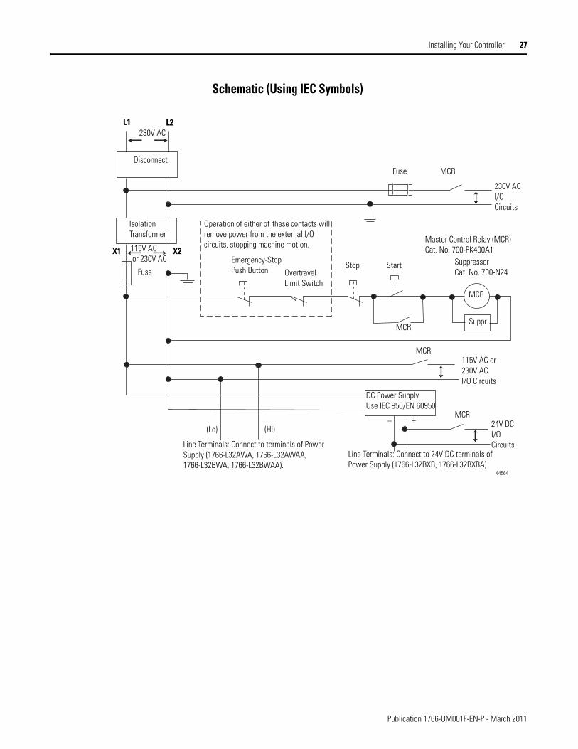
Master Control Relay A hard-wired master control relay (MCR) provides a reliable means for emergency machine shutdown. Since the master control relay allows the placement of several emergency-stop switches in different locations, its installation is important from a safety standpoint. Overtravel limit switches or mushroom-head push buttons are wired in series so that when any of them opens, the master control relay is de-energized. This removes power to input and output device circuits. Refer to the figures on pages 27 and 28.
Place the main power disconnect switch where operators and maintenance personnel have quick and easy access to it. If you mount a disconnect switch inside the controller enclosure, place the switch operating handle on the outside of the enclosure, so that you can disconnect power without opening the enclosure.
Whenever any of the emergency-stop switches are opened, power to input and output devices should be removed.
TIP Do not bring in unfiltered outside air. Place the controller in an enclosure to protect it from a corrosive atmosphere. Harmful contaminants or dirt could cause improper operation or damage to components. In extreme cases, you may need to use air conditioning to protect against heat build-up within the enclosure.
ATTENTION Never alter these circuits to defeat their function since serious injury and/or machine damage could result.
TIP If you are using an external DC power supply, interrupt the DC output side rather than the AC line side of the supply to avoid the additional delay of power supply turn-off.
The AC line of the DC output power supply should be fused.
Connect a set of master control relays in series with the DC power supplying the input and output circuits.
Publication 1766-UM001F-EN-P - March 2011
26 Installing Your Controller
When you use the master control relay to remove power from the external I/O circuits, power continues to be provided to the controller’s power supply so that diagnostic indicators on the processor can still be observed.
The master control relay is not a substitute for a disconnect to the controller. It is intended for any situation where the operator must quickly de-energize I/O devices only. When inspecting or installing terminal connections, replacing output fuses, or working on equipment within the enclosure, use the disconnect to shut off power to the rest of the system.
Using Emergency-Stop Switches
When using emergency-stop switches, adhere to the following points:
• Do not program emergency-stop switches in the controller program. Any emergency-stop switch should turn off all machine power by turning off the master control relay.
• Observe all applicable local codes concerning the placement and labeling of emergency-stop switches.
• Install emergency-stop switches and the master control relay in your system. Make certain that relay contacts have a sufficient rating for your application. Emergency-stop switches must be easy to reach.
• In the following illustration, input and output circuits are shown with MCR protection. However, in most applications, only output circuits require MCR protection.
The following illustrations show the Master Control Relay wired in a grounded system.
TIP Do not control the master control relay with the controller. Provide the operator with the safety of a direct connection between an emergency-stop switch and the master control relay.
TIP In most applications input circuits do not require MCR protection; however, if you need to remove power from all field devices, you must include MCR contacts in series with input power wiring.
Publication 1766-UM001F-EN-P - March 2011
Installing Your Controller 27
Schematic (Using IEC Symbols)
Disconnect
Isolation Transformer
Emergency-Stop Push Button
Fuse MCR
230V ACI/O Circuits
Operation of either of these contacts will remove power from the external I/O circuits, stopping machine motion.
Fuse Overtravel Limit Switch
MCR
MCR
MCR
Stop Start
Line Terminals: Connect to terminals of Power Supply (1766-L32AWA, 1766-L32AWAA, 1766-L32BWA, 1766-L32BWAA).
115V AC or 230V ACI/O Circuits
L1 L2230V AC
Master Control Relay (MCR)Cat. No. 700-PK400A1
SuppressorCat. No. 700-N24
MCR
Suppr.
24V DCI/O Circuits
(Lo) (Hi)
DC Power Supply.Use IEC 950/EN 60950
X1 X2115V AC or 230V AC
Line Terminals: Connect to 24V DC terminals of Power Supply (1766-L32BXB, 1766-L32BXBA)
_ +
44564
Publication 1766-UM001F-EN-P - March 2011
28 Installing Your Controller
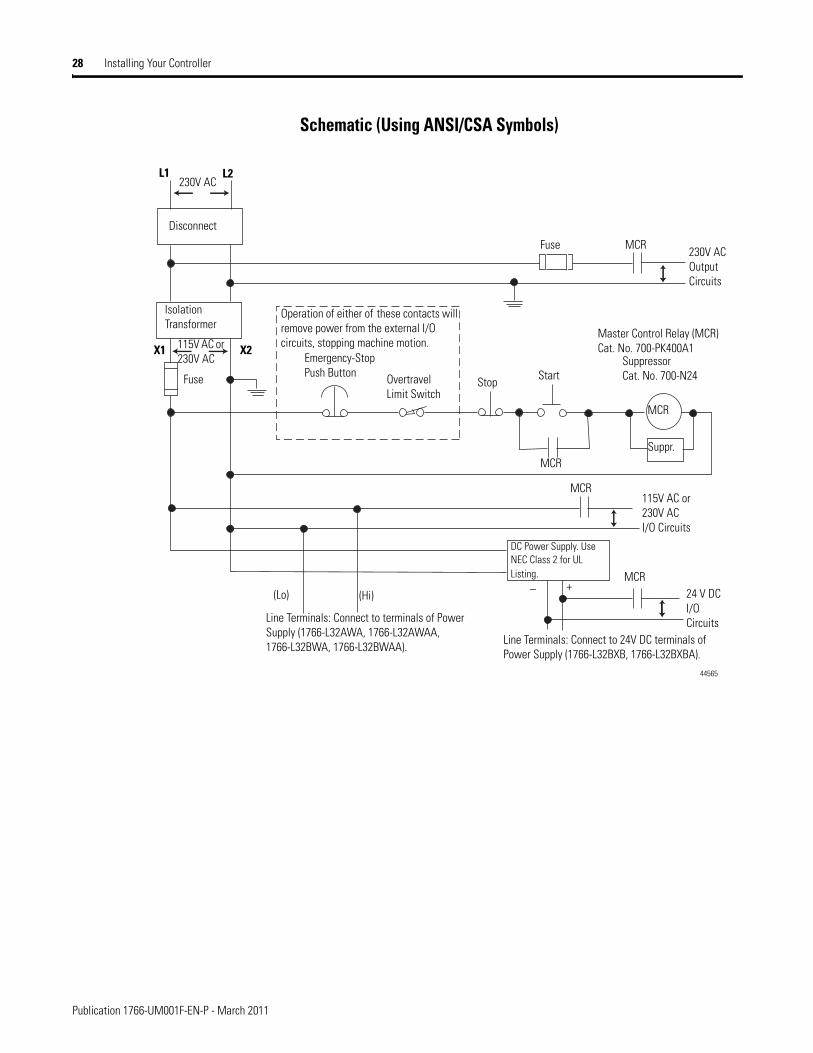
Schematic (Using ANSI/CSA Symbols)
Emergency-Stop Push Button
230V AC
Operation of either of these contacts will remove power from the external I/O circuits, stopping machine motion.
Fuse MCR
Fuse
MCR
MCR
MCR
Stop Start
Line Terminals: Connect to terminals of Power Supply (1766-L32AWA, 1766-L32AWAA, 1766-L32BWA, 1766-L32BWAA).
Line Terminals: Connect to 24V DC terminals of Power Supply (1766-L32BXB, 1766-L32BXBA).
230V AC Output Circuits
Disconnect
Isolation Transformer
115V AC or 230V AC I/O Circuits
L1 L2
Master Control Relay (MCR)Cat. No. 700-PK400A1
SuppressorCat. No. 700-N24
(Lo) (Hi)
DC Power Supply. Use NEC Class 2 for UL Listing.
X1 X2115V AC or 230V AC
_ +
MCR
24 V DC I/O Circuits
Suppr.
Overtravel Limit Switch
44565
Publication 1766-UM001F-EN-P - March 2011
Installing Your Controller 29
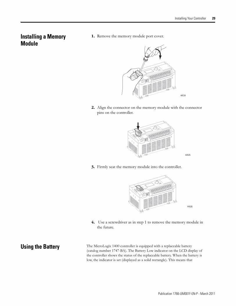
Installing a Memory Module
1. Remove the memory module port cover.
2. Align the connector on the memory module with the connector pins on the controller.
3. Firmly seat the memory module into the controller.
4. Use a screwdriver as in step 1 to remove the memory module in the future.
Using the Battery The MicroLogix 1400 controller is equipped with a replaceable battery (catalog number 1747-BA). The Battery Low indicator on the LCD display of the controller shows the status of the replaceable battery. When the battery is low, the indicator is set (displayed as a solid rectangle). This means that
44534
ModuleMemory
44535
ModuleMemory
44536
Publication 1766-UM001F-EN-P - March 2011
30 Installing Your Controller
either the battery wire connector is disconnected, or the battery may fail within 2 weeks if it is connected.
IMPORTANT The MicroLogix 1400 controller ships with the battery wire connector connected.Ensure that the battery wire connector is inserted into the connector port if your application needs battery power. For example, when using a real-time clock (RTC).Replacing the battery when the controller is powered down will lose all user application memory. Replace the battery when the controller is powered on.Refer to the SLC 500 Lithium Battery Installation Instructions, publication 1747-IN515, for more information on installation, handling, usage, storage, and disposal of the battery.
See RTC Battery Operation on page 162, for more information on the use of the battery in relation with RTC.
WARNINGWhen you connect or disconnect the battery an electrical arc can occur. This could cause an explosion in hazardous location installations. Be sure that the area is nonhazardous before proceeding.
For Safety information on the handling of lithium batteries, including handling and disposal of leaking batteries, see Guidelines for Handling Lithium Batteries, publication AG 5-4.
IMPORTANT When the controller’s Battery Low indicator is set (displayed as a solid rectangle) with the battery wire connector connected, you should install a new battery immediately.
Publication 1766-UM001F-EN-P - March 2011
Installing Your Controller 31
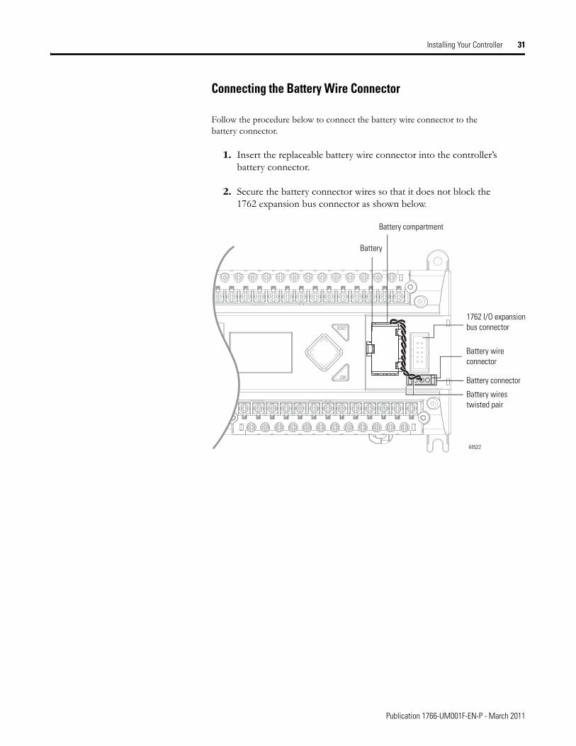
Connecting the Battery Wire Connector
Follow the procedure below to connect the battery wire connector to the battery connector.
1. Insert the replaceable battery wire connector into the controller’s battery connector.
2. Secure the battery connector wires so that it does not block the 1762 expansion bus connector as shown below.
1762 I/O expansion bus connector
Battery wirestwisted pair
Battery
Battery wire connector
Battery connector
44522
Battery compartment
Publication 1766-UM001F-EN-P - March 2011
32 Installing Your Controller
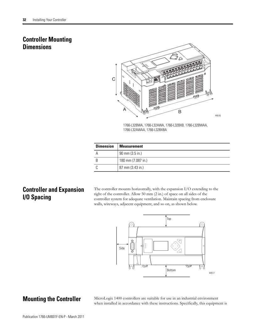
Controller Mounting Dimensions
Controller and Expansion I/O Spacing
The controller mounts horizontally, with the expansion I/O extending to the right of the controller. Allow 50 mm (2 in.) of space on all sides of the controller system for adequate ventilation. Maintain spacing from enclosure walls, wireways, adjacent equipment, and so on, as shown below.
Mounting the Controller MicroLogix 1400 controllers are suitable for use in an industrial environment when installed in accordance with these instructions. Specifically, this equipment is
Dimension Measurement
A 90 mm (3.5 in.)
B 180 mm (7.087 in.)
C 87 mm (3.43 in.)
C
BA
1766-L32BWA, 1766-L32AWA, 1766-L32BXB, 1766-L32BWAA, 1766-L32AWAA, 1766-L32BXBA
44516
ESC
OK
Top
Bottom
Side
44517
Publication 1766-UM001F-EN-P - March 2011
Installing Your Controller 33
intended for use in clean, dry environments (Pollution degree 2(1)) and to circuits not
exceeding Over Voltage Category II(2) (IEC 60664-1).(3)
(1) Pollution Degree 2 is an environment where, normally, only non-conductive pollution occurs except that occasionally a temporary conductivity caused by condensation shall be expected.
(2) Over Voltage Category II is the load level section of the electrical distribution system. At this level transient voltages are controlled and do not exceed the impulse voltage capability of the product’s insulation.
(3) Pollution Degree 2 and Over Voltage Category II are International Electrotechnical Commission (IEC) designations.
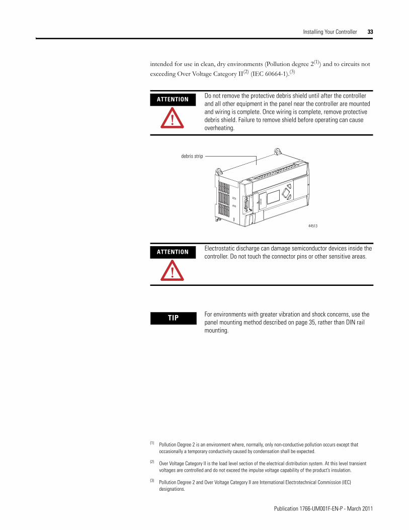
ATTENTION Do not remove the protective debris shield until after the controller and all other equipment in the panel near the controller are mounted and wiring is complete. Once wiring is complete, remove protective debris shield. Failure to remove shield before operating can cause overheating.
ATTENTION Electrostatic discharge can damage semiconductor devices inside the controller. Do not touch the connector pins or other sensitive areas.
TIP For environments with greater vibration and shock concerns, use the panel mounting method described on page 35, rather than DIN rail mounting.
debris strip
44513
Publication 1766-UM001F-EN-P - March 2011
34 Installing Your Controller
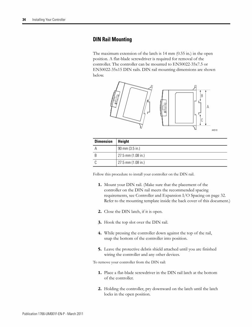
DIN Rail Mounting
The maximum extension of the latch is 14 mm (0.55 in.) in the open position. A flat-blade screwdriver is required for removal of the controller. The controller can be mounted to EN50022-35x7.5 or EN50022-35x15 DIN rails. DIN rail mounting dimensions are shown below.
Follow this procedure to install your controller on the DIN rail.
1. Mount your DIN rail. (Make sure that the placement of the controller on the DIN rail meets the recommended spacing requirements, see Controller and Expansion I/O Spacing on page 32. Refer to the mounting template inside the back cover of this document.)
2. Close the DIN latch, if it is open.
3. Hook the top slot over the DIN rail.
4. While pressing the controller down against the top of the rail, snap the bottom of the controller into position.
5. Leave the protective debris shield attached until you are finished wiring the controller and any other devices.
To remove your controller from the DIN rail:
1. Place a flat-blade screwdriver in the DIN rail latch at the bottom of the controller.
2. Holding the controller, pry downward on the latch until the latch locks in the open position.
Dimension Height
A 90 mm (3.5 in.)
B 27.5 mm (1.08 in.)
C 27.5 mm (1.08 in.)
A
B
C
44518
Publication 1766-UM001F-EN-P - March 2011
Installing Your Controller 35
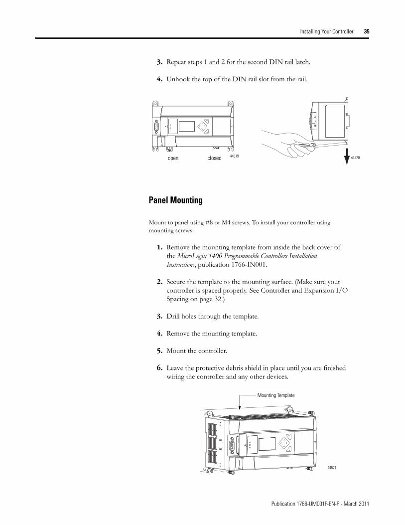
3. Repeat steps 1 and 2 for the second DIN rail latch.
4. Unhook the top of the DIN rail slot from the rail.
Panel Mounting
Mount to panel using #8 or M4 screws. To install your controller using mounting screws:
1. Remove the mounting template from inside the back cover of the MicroLogix 1400 Programmable Controllers Installation Instructions, publication 1766-IN001.
2. Secure the template to the mounting surface. (Make sure your controller is spaced properly. See Controller and Expansion I/O Spacing on page 32.)
3. Drill holes through the template.
4. Remove the mounting template.
5. Mount the controller.
6. Leave the protective debris shield in place until you are finished wiring the controller and any other devices.
ESC
OK
open closed 44519 44520
ESC
OK
Mounting Template
44521
Publication 1766-UM001F-EN-P - March 2011
36 Installing Your Controller
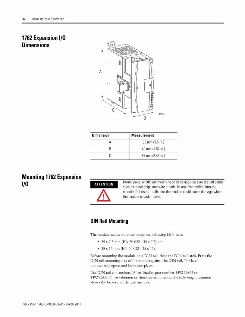
1762 Expansion I/O Dimensions
Mounting 1762 Expansion I/O
DIN Rail Mounting
The module can be mounted using the following DIN rails:
• 35 x 7.5 mm (EN 50 022 - 35 x 7.5), or
• 35 x 15 mm (EN 50 022 - 35 x 15).
Before mounting the module on a DIN rail, close the DIN rail latch. Press the DIN rail mounting area of the module against the DIN rail. The latch momentarily opens and locks into place.
Use DIN rail end anchors (Allen-Bradley part number 1492-EA35 or 1492-EAH35) for vibration or shock environments. The following illustration shows the location of the end anchors.
Dimension Measurement
A 90 mm (3.5 in.)
B 40 mm (1.57 in.)
C 87 mm (3.43 in.)
A
B
C 44567
ATTENTION During panel or DIN rail mounting of all devices, be sure that all debris such as metal chips and wire stands, is kept from falling into the module. Debris that falls into the module could cause damage when the module is under power.
Publication 1766-UM001F-EN-P - March 2011
Installing Your Controller 37
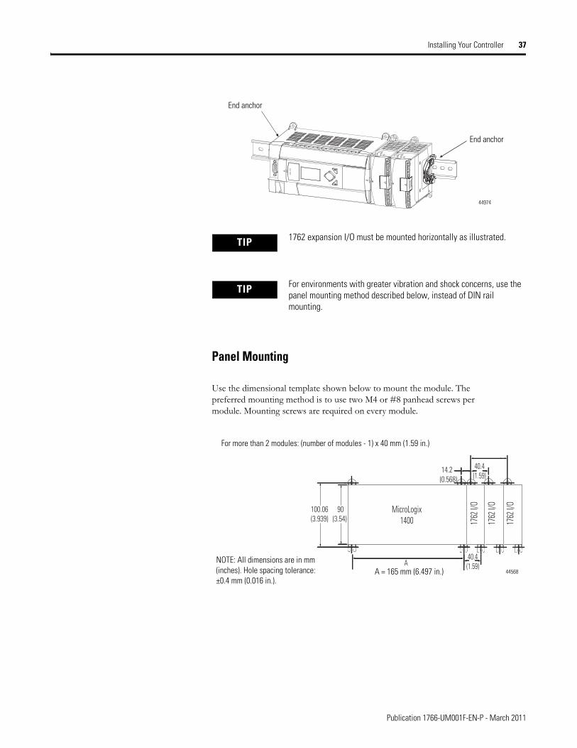
Panel Mounting
Use the dimensional template shown below to mount the module. The preferred mounting method is to use two M4 or #8 panhead screws per module. Mounting screws are required on every module.
TIP 1762 expansion I/O must be mounted horizontally as illustrated.
TIP For environments with greater vibration and shock concerns, use the panel mounting method described below, instead of DIN rail mounting.
End anchor
End anchor
44974
90(3.54)
100.06(3.939)
40.4(1.59)A
40.4(1.59)
14.2(0.568)
MicroLogix1400 17
62 I/
O
1762
I/O
1762
I/O
For more than 2 modules: (number of modules - 1) x 40 mm (1.59 in.)
NOTE: All dimensions are in mm (inches). Hole spacing tolerance: ±0.4 mm (0.016 in.).
A = 165 mm (6.497 in.) 44568
Publication 1766-UM001F-EN-P - March 2011
38 Installing Your Controller
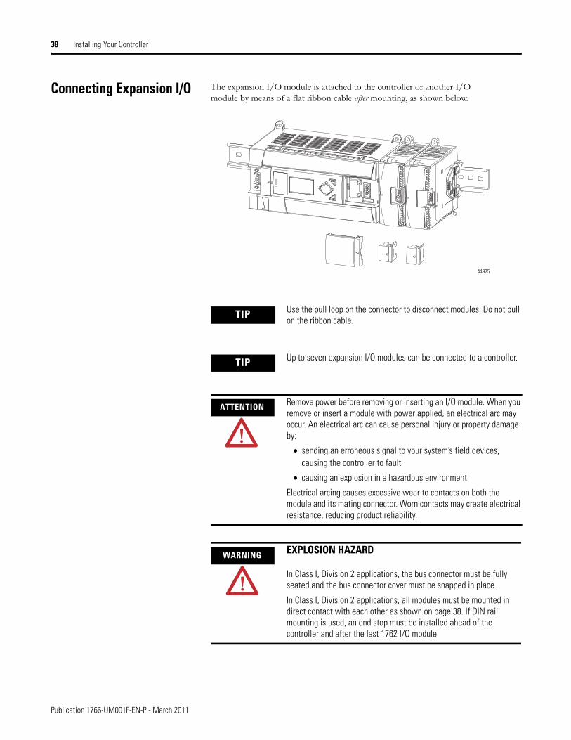
Connecting Expansion I/O The expansion I/O module is attached to the controller or another I/O module by means of a flat ribbon cable after mounting, as shown below.
TIP Use the pull loop on the connector to disconnect modules. Do not pull on the ribbon cable.
TIP Up to seven expansion I/O modules can be connected to a controller.
ATTENTION Remove power before removing or inserting an I/O module. When you remove or insert a module with power applied, an electrical arc may occur. An electrical arc can cause personal injury or property damage by:
• sending an erroneous signal to your system’s field devices, causing the controller to fault
• causing an explosion in a hazardous environment
Electrical arcing causes excessive wear to contacts on both the module and its mating connector. Worn contacts may create electrical resistance, reducing product reliability.
WARNING EXPLOSION HAZARD
In Class I, Division 2 applications, the bus connector must be fully seated and the bus connector cover must be snapped in place.
In Class I, Division 2 applications, all modules must be mounted in direct contact with each other as shown on page 38. If DIN rail mounting is used, an end stop must be installed ahead of the controller and after the last 1762 I/O module.
44975
Publication 1766-UM001F-EN-P - March 2011

Installing Your Controller 39
Notes:
Publication 1766-UM001F-EN-P - March 2011

40 Installing Your Controller
Publication 1766-UM001F-EN-P - March 2011
Chapter 3
Wiring Your Controller
This chapter describes how to wire your controller and expansion I/O. Topics include:
· wire requirements
· using surge suppressors
· grounding the controller
· wiring diagrams
· sinking and sourcing wiring diagrams
· controller I/O wiring
· wiring your analog channels
· expansion I/O wiring
Wiring Requirements Wiring Recommendation
· Allow for at least 50 mm. (2 in.) between I/O wiring ducts or terminal strips and the controller.
· Route incoming power to the controller by a path separate from the device wiring. Where paths must cross, their intersection should be perpendicular.
ATTENTION Before you install and wire any device, disconnect power to the controller system.
ATTENTION Calculate the maximum possible current in each power and common wire. Observe all electrical codes dictating the maximum current allowable for each wire size. Current above the maximum ratings may cause wiring to overheat, which can cause damage.
United States Only: If the controller is installed within a potentially hazardous environment, all wiring must comply with the requirements stated in the National Electrical Code 501-10 (b).
TIP Do not run signal or communications wiring and power wiring in the same conduit. Wires with different signal characteristics should be routed by separate paths.
41 Publication 1766-UM001F-EN-P - March 2011
42 Wiring Your Controller
· Separate wiring by signal type. Bundle wiring with similar electrical characteristics together.
· Separate input wiring from output wiring.
· Label wiring to all devices in the system. Use tape, shrink-tubing, or other dependable means for labeling purposes. In addition to labeling, use colored insulation to identify wiring based on signal characteristics. For example, you may use blue for DC wiring and red for AC wiring.
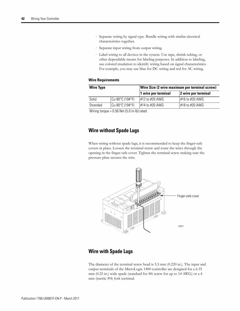
Wire without Spade Lugs
When wiring without spade lugs, it is recommended to keep the finger-safe covers in place. Loosen the terminal screw and route the wires through the opening in the finger-safe cover. Tighten the terminal screw making sure the pressure plate secures the wire.
Wire with Spade Lugs
The diameter of the terminal screw head is 5.5 mm (0.220 in.). The input and output terminals of the MicroLogix 1400 controller are designed for a 6.35 mm (0.25 in.) wide spade (standard for #6 screw for up to 14 AWG) or a 4 mm (metric #4) fork terminal.
Wire Requirements
Wire Type Wire Size (2 wire maximum per terminal screw)1 wire per terminal 2 wire per terminal
Solid Cu-90°C (194°F) #12 to #20 AWG #16 to #20 AWG
Stranded Cu-90°C (194°F) #14 to #20 AWG #18 to #20 AWG
Wiring torque = 0.56 Nm (5.0 in-lb) rated
Finger-safe cover
44527
Publication 1766-UM001F-EN-P - March 2011
Wiring Your Controller 43
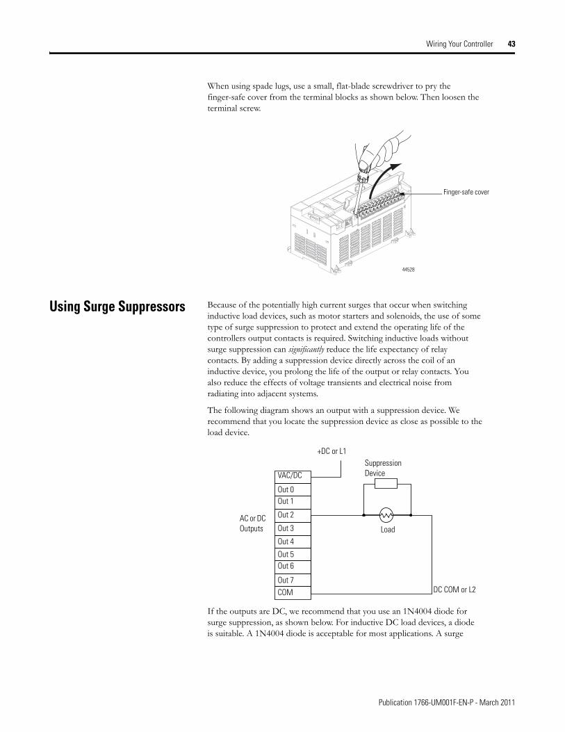
When using spade lugs, use a small, flat-blade screwdriver to pry the finger-safe cover from the terminal blocks as shown below. Then loosen the terminal screw.
Using Surge Suppressors Because of the potentially high current surges that occur when switching inductive load devices, such as motor starters and solenoids, the use of some type of surge suppression to protect and extend the operating life of the controllers output contacts is required. Switching inductive loads without surge suppression can significantly reduce the life expectancy of relay contacts. By adding a suppression device directly across the coil of an inductive device, you prolong the life of the output or relay contacts. You also reduce the effects of voltage transients and electrical noise from radiating into adjacent systems.
The following diagram shows an output with a suppression device. We recommend that you locate the suppression device as close as possible to the load device.
If the outputs are DC, we recommend that you use an 1N4004 diode for surge suppression, as shown below. For inductive DC load devices, a diode is suitable. A 1N4004 diode is acceptable for most applications. A surge
Finger-safe cover
44528
+DC or L1Suppression Device
DC COM or L2
AC or DC Outputs Load
VAC/DC
Out 0Out 1
Out 2
Out 3
Out 4
Out 5Out 6
Out 7COM
Publication 1766-UM001F-EN-P - March 2011
44 Wiring Your Controller
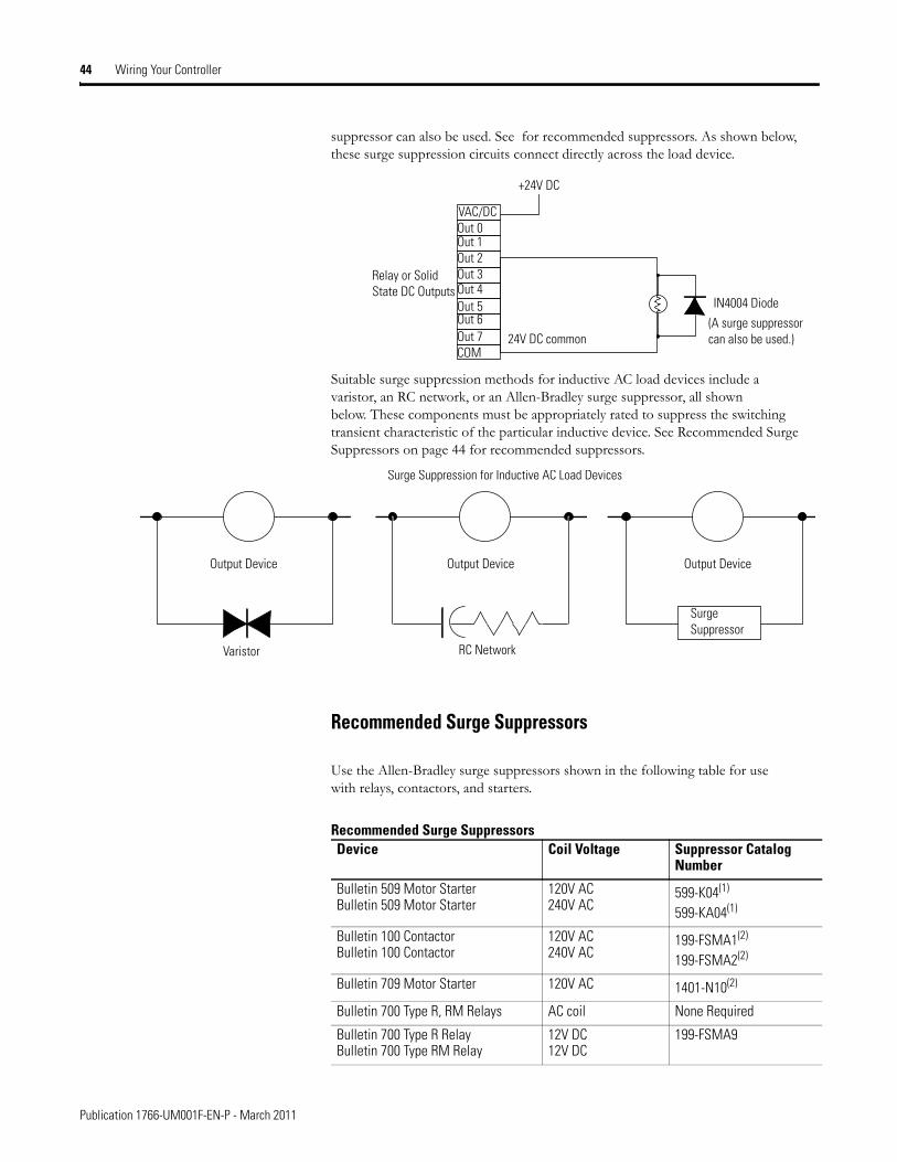
suppressor can also be used. See for recommended suppressors. As shown below, these surge suppression circuits connect directly across the load device.
Suitable surge suppression methods for inductive AC load devices include a varistor, an RC network, or an Allen-Bradley surge suppressor, all shown below. These components must be appropriately rated to suppress the switching transient characteristic of the particular inductive device. See Recommended Surge Suppressors on page 44 for recommended suppressors.
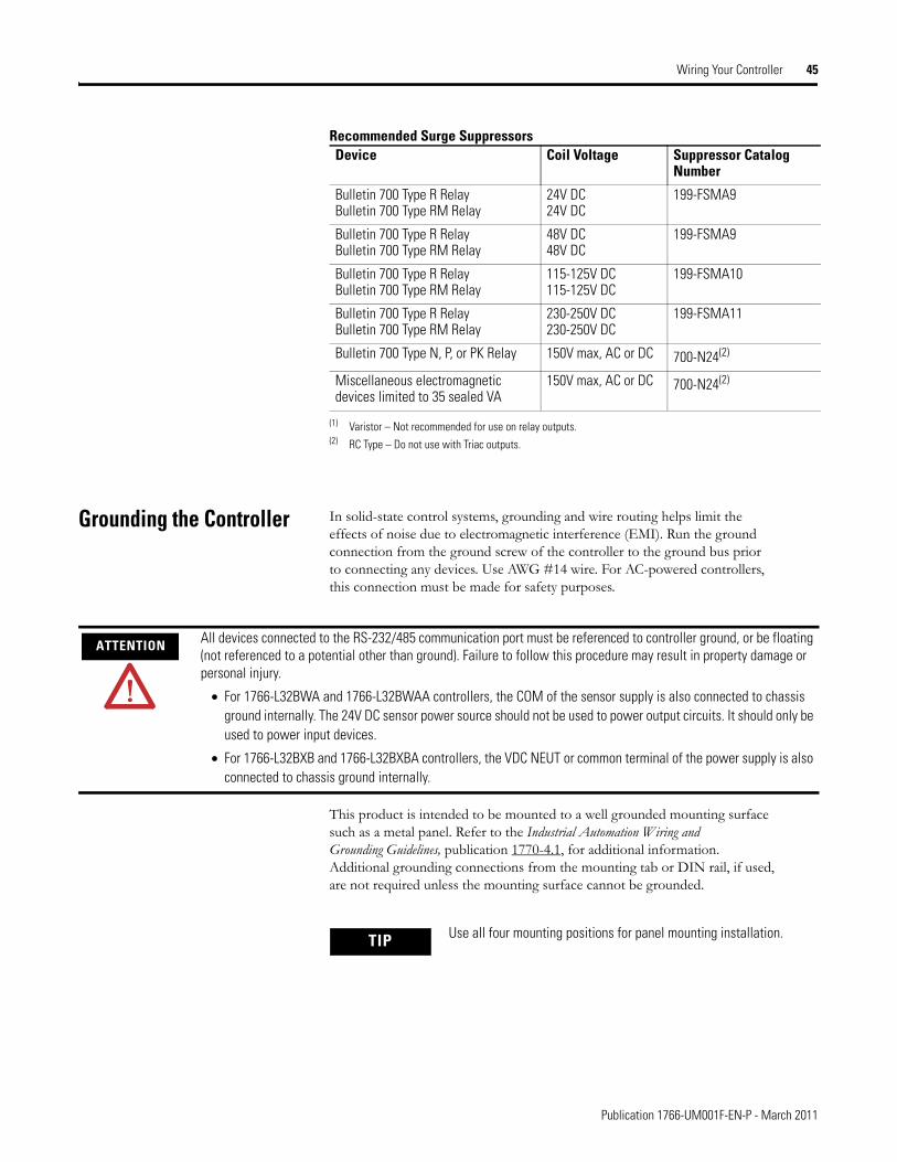
Recommended Surge Suppressors
Use the Allen-Bradley surge suppressors shown in the following table for use with relays, contactors, and starters.
+24V DC
IN4004 Diode
Relay or Solid State DC Outputs
24V DC common
VAC/DCOut 0Out 1Out 2Out 3Out 4Out 5Out 6Out 7COM
(A surge suppressor can also be used.)
Surge Suppression for Inductive AC Load Devices
Output Device Output DeviceOutput Device
Varistor RC Network
Surge Suppressor
Recommended Surge SuppressorsDevice Coil Voltage Suppressor Catalog
Number
Bulletin 509 Motor StarterBulletin 509 Motor Starter
120V AC240V AC
599-K04(1)
599-KA04(1)
Bulletin 100 ContactorBulletin 100 Contactor
120V AC240V AC
199-FSMA1(2)
199-FSMA2(2)
Bulletin 709 Motor Starter 120V AC 1401-N10(2)
Bulletin 700 Type R, RM Relays AC coil None Required
Bulletin 700 Type R RelayBulletin 700 Type RM Relay
12V DC12V DC
199-FSMA9
Publication 1766-UM001F-EN-P - March 2011
Wiring Your Controller 45
Grounding the Controller In solid-state control systems, grounding and wire routing helps limit the effects of noise due to electromagnetic interference (EMI). Run the ground connection from the ground screw of the controller to the ground bus prior to connecting any devices. Use AWG #14 wire. For AC-powered controllers, this connection must be made for safety purposes.
This product is intended to be mounted to a well grounded mounting surface such as a metal panel. Refer to the Industrial Automation Wiring and Grounding Guidelines, publication 1770-4.1, for additional information. Additional grounding connections from the mounting tab or DIN rail, if used, are not required unless the mounting surface cannot be grounded.
Bulletin 700 Type R RelayBulletin 700 Type RM Relay
24V DC24V DC
199-FSMA9
Bulletin 700 Type R RelayBulletin 700 Type RM Relay
48V DC48V DC
199-FSMA9
Bulletin 700 Type R RelayBulletin 700 Type RM Relay
115-125V DC115-125V DC
199-FSMA10
Bulletin 700 Type R RelayBulletin 700 Type RM Relay
230-250V DC230-250V DC
199-FSMA11
Bulletin 700 Type N, P, or PK Relay 150V max, AC or DC 700-N24(2)
Miscellaneous electromagnetic devices limited to 35 sealed VA
150V max, AC or DC 700-N24(2)
(1) Varistor – Not recommended for use on relay outputs.(2) RC Type – Do not use with Triac outputs.
Recommended Surge SuppressorsDevice Coil Voltage Suppressor Catalog
Number
ATTENTION All devices connected to the RS-232/485 communication port must be referenced to controller ground, or be floating (not referenced to a potential other than ground). Failure to follow this procedure may result in property damage or personal injury.
• For 1766-L32BWA and 1766-L32BWAA controllers, the COM of the sensor supply is also connected to chassis ground internally. The 24V DC sensor power source should not be used to power output circuits. It should only be used to power input devices.
• For 1766-L32BXB and 1766-L32BXBA controllers, the VDC NEUT or common terminal of the power supply is also connected to chassis ground internally.
TIP Use all four mounting positions for panel mounting installation.
Publication 1766-UM001F-EN-P - March 2011
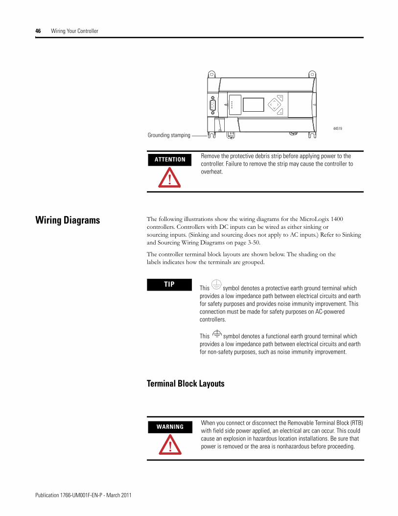
46 Wiring Your Controller
Wiring Diagrams The following illustrations show the wiring diagrams for the MicroLogix 1400 controllers. Controllers with DC inputs can be wired as either sinking or sourcing inputs. (Sinking and sourcing does not apply to AC inputs.) Refer to Sinking and Sourcing Wiring Diagrams on page 3-50.
The controller terminal block layouts are shown below. The shading on the labels indicates how the terminals are grouped.
Terminal Block Layouts
ATTENTION Remove the protective debris strip before applying power to the controller. Failure to remove the strip may cause the controller to overheat.
ESC
OK
Grounding stamping44519
TIP This symbol denotes a protective earth ground terminal which provides a low impedance path between electrical circuits and earth for safety purposes and provides noise immunity improvement. This connection must be made for safety purposes on AC-powered controllers.
This symbol denotes a functional earth ground terminal which provides a low impedance path between electrical circuits and earth for non-safety purposes, such as noise immunity improvement.
WARNINGWhen you connect or disconnect the Removable Terminal Block (RTB) with field side power applied, an electrical arc can occur. This could cause an explosion in hazardous location installations. Be sure that power is removed or the area is nonhazardous before proceeding.
Publication 1766-UM001F-EN-P - March 2011
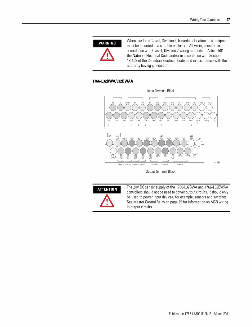
Wiring Your Controller 47
1766-L32BWA/L32BWAA
WARNINGWhen used in a Class I, Division 2, hazardous location, this equipment must be mounted in a suitable enclosure. All wiring must be in accordance with Class I, Division 2 wiring methods of Article 501 of the National Electrical Code and/or in accordance with Section 18-1J2 of the Canadian Electrical Code, and in accordance with the authority having jurisdiction.
ATTENTION The 24V DC sensor supply of the 1766-L32BWA and 1766-L32BWAA controllers should not be used to power output circuits. It should only be used to power input devices, for example, sensors and switches. See Master Control Relay on page 25 for information on MCR wiring in output circuits.
IN1
IN0 IN2
IN3COM 0
IV0(+) IV2(+)COM 1
IV1(+) IV3(+)
IN5 IN7
IN4 IN6 COM 2
IN8 IN10
IN9 IN11
COM 3 IN13 IN15 IN17 IN19
IN12 IN14 IN16 IN18 COMANA
L1
DC0
OV1OUT0 OUT1 OUT2 OUT3 OUT4
OUT5
OUT7 OUT8 OUT10
OUT6 OUT9 OUT11 OV0
VACL2/NVAC
VACDC1VAC
DC2VAC
DC3VAC
DC4VAC
DC6VAC
COMANADC5
VAC
Group 0 Group 1 Group 2 Group 3 Group 5Group 4 Group 6
Input Terminal Block
Output Terminal Block
44524
Publication 1766-UM001F-EN-P - March 2011
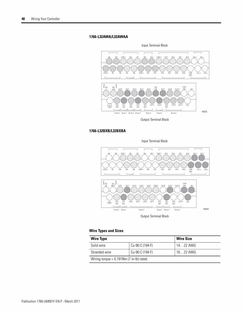
48 Wiring Your Controller
1766-L32AWA/L32AWAA
1766-L32BXB/L32BXBA
Wire Types and Sizes
Wire Type Wire Size
Solid wire Cu-90⋅C (194⋅F) 14…22 AWG
Stranded wire Cu-90⋅C (194⋅F) 16…22 AWG
Wiring torque = 0.791Nm (7 in-lb) rated.
IN1
IN0 IN2
IN3COM 0
IV0(+) IV2(+)COM 1
IV1(+) IV3(+)
IN5 IN7
IN4 IN6 COM 2
IN8 IN10
IN9 IN11
COM 3 IN13 IN15 IN17 IN19
IN12 IN14 IN16 IN18 COMANA
L1
DC0
OV1OUT0 OUT1 OUT2 OUT3 OUT4
OUT5
OUT7 OUT8 OUT10
OUT6 OUT9 OUT11 OV0
VACL2/NVAC
VACDC1VAC
DC2VAC
DC3VAC
DC4VAC
DC6VAC
COMANADC5
VAC
Group 0 Group 1 Group 2 Group 3 Group 5Group 4 Group 6
Input Terminal Block
Output Terminal Block
44525
IN1
IN0 IN2
IN3COM 0
IV0(+) IV2(+)COM 1
IV1(+) IV3(+)
IN5 IN7
IN4 IN6 COM 2
IN8 IN10
IN9 IN11
COM 3 IN13 IN15 IN17 IN19
IN12 IN14 IN16 IN18 COMANA
+24
DC0
OV1OUT0 OUT1 OUT2 OUT4 OUT6
OUT7
OUT8 OUT9 OUT10
OUT11 OV0
VDCNEUTVDC
VACDC1VAC
VDC2 OUT3 OUT5 DC4VAC
COMANACOM 2
DC3VAC
DC5VAC
Group 0 Group 1 Group 3 Group 4 Group 5Group 2
Input Terminal Block
Output Terminal Block
44526
Publication 1766-UM001F-EN-P - March 2011
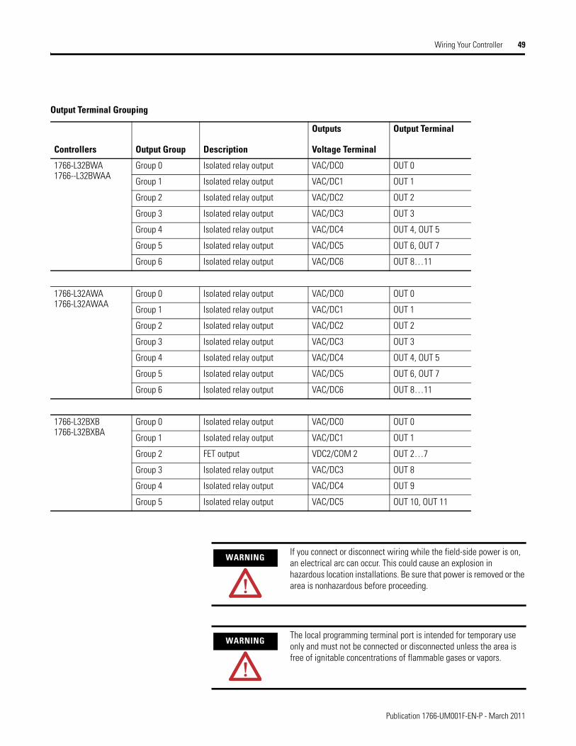
Wiring Your Controller 49
Output Terminal Grouping
Controllers Output Group Description
Outputs
Voltage Terminal
Output Terminal
1766-L32BWA1766--L32BWAA
Group 0 Isolated relay output VAC/DC0 OUT 0
Group 1 Isolated relay output VAC/DC1 OUT 1
Group 2 Isolated relay output VAC/DC2 OUT 2
Group 3 Isolated relay output VAC/DC3 OUT 3
Group 4 Isolated relay output VAC/DC4 OUT 4, OUT 5
Group 5 Isolated relay output VAC/DC5 OUT 6, OUT 7
Group 6 Isolated relay output VAC/DC6 OUT 8…11
1766-L32AWA1766-L32AWAA
Group 0 Isolated relay output VAC/DC0 OUT 0
Group 1 Isolated relay output VAC/DC1 OUT 1
Group 2 Isolated relay output VAC/DC2 OUT 2
Group 3 Isolated relay output VAC/DC3 OUT 3
Group 4 Isolated relay output VAC/DC4 OUT 4, OUT 5
Group 5 Isolated relay output VAC/DC5 OUT 6, OUT 7
Group 6 Isolated relay output VAC/DC6 OUT 8…11
1766-L32BXB1766-L32BXBA
Group 0 Isolated relay output VAC/DC0 OUT 0
Group 1 Isolated relay output VAC/DC1 OUT 1
Group 2 FET output VDC2/COM 2 OUT 2…7
Group 3 Isolated relay output VAC/DC3 OUT 8
Group 4 Isolated relay output VAC/DC4 OUT 9
Group 5 Isolated relay output VAC/DC5 OUT 10, OUT 11
WARNINGIf you connect or disconnect wiring while the field-side power is on, an electrical arc can occur. This could cause an explosion in hazardous location installations. Be sure that power is removed or the area is nonhazardous before proceeding.
WARNINGThe local programming terminal port is intended for temporary use only and must not be connected or disconnected unless the area is free of ignitable concentrations of flammable gases or vapors.
Publication 1766-UM001F-EN-P - March 2011
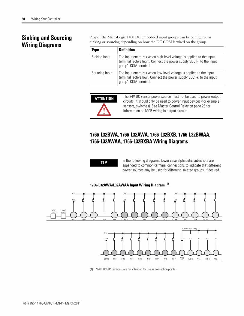
50 Wiring Your Controller
Sinking and Sourcing Wiring Diagrams
Any of the MicroLogix 1400 DC embedded input groups can be configured as sinking or sourcing depending on how the DC COM is wired on the group.
1766-L32BWA, 1766-L32AWA, 1766-L32BXB, 1766-L32BWAA, 1766-L32AWAA, 1766-L32BXBA Wiring Diagrams
1766-L32AWA/L32AWAA Input Wiring Diagram (1)
(1) “NOT USED” terminals are not intended for use as connection points.
Type Definition
Sinking Input The input energizes when high-level voltage is applied to the input terminal (active high). Connect the power supply VDC (-) to the input group’s COM terminal.
Sourcing Input The input energizes when low-level voltage is applied to the input terminal (active low). Connect the power supply VDC (+) to the input group’s COM terminal.
ATTENTION The 24V DC sensor power source must not be used to power output circuits. It should only be used to power input devices (for example. sensors, switches). See Master Control Relay on page 25 for information on MCR wiring in output circuits.
TIP In the following diagrams, lower case alphabetic subscripts are appended to common-terminal connections to indicate that different power sources may be used for different isolated groups, if desired.
NOTUSED
NOTUSED
COM 0
L2a
L1a
IN0 IN1 IN2 IN3 COM 1
L2b
L1b
IN4 IN5 IN6 IN7 COM 2
L2c
L1c
IN8 IN9 IN10 IN11
COM 3
L2d
L1d
IN12 IN13 IN14 IN15 IN17 IN18 IN19IN16COMANA
AGND AIN0
IV0(+) IV1(+) IV2(+) IV3(+)
AIN1 AIN2 AIN3
1766-L32AWAA only
Publication 1766-UM001F-EN-P - March 2011
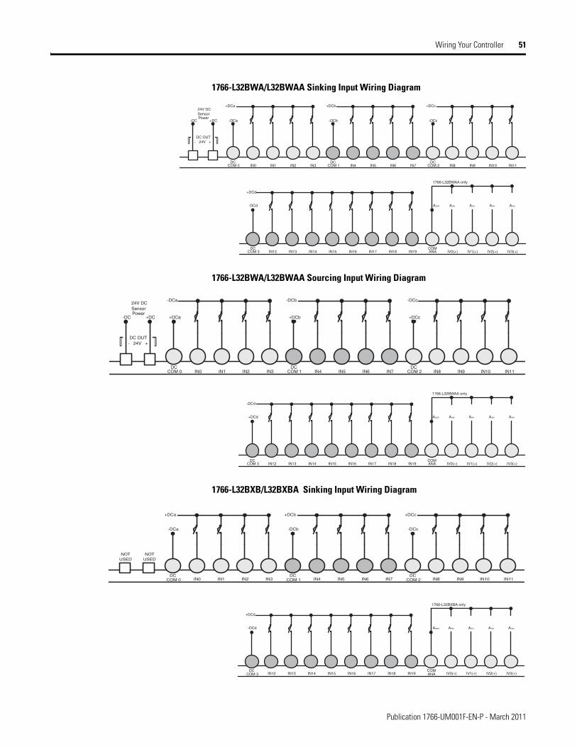
Wiring Your Controller 51
1766-L32BWA/L32BWAA Sinking Input Wiring Diagram
1766-L32BWA/L32BWAA Sourcing Input Wiring Diagram
1766-L32BXB/L32BXBA Sinking Input Wiring Diagram
DCCOM 0
-DCa
+DCa
IN0 IN1 IN2 IN3DC
COM 1
-DCb
+DCb
IN4 IN5 IN6 IN7DC
COM 2
-DCc
+DCc
IN8 IN9 IN10 IN11
-DC +DC
24V DCSensorPower
DC OUT- 24V +
DCCOM 3
-DCd
+DCd
IN12 IN13 IN14 IN15 IN17 IN18 IN19IN16COMANA
AGND AIN0
IV0(+) IV1(+) IV2(+) IV3(+)
AIN1 AIN2 AIN3
1766-L32BWAA only
DCCOM 0
+DCa
-DCa
IN0 IN1 IN2 IN3DC
COM 1
+DCb
-DCb
IN4 IN5 IN6 IN7DC
COM 2
+DCc
-DCc
IN8 IN9 IN10 IN11
-DC +DC
24V DCSensorPower
DC OUT- 24V +
DCCOM 3
+DCd
-DCd
IN12 IN13 IN14 IN15 IN17 IN18 IN19IN16COMANA
AGND AIN0
IV0(+) IV1(+) IV2(+) IV3(+)
AIN1 AIN2 AIN3
1766-L32BWAA only
DCCOM 0
-DCa
+DCa
IN0 IN1 IN2 IN3DC
COM 1
-DCb
+DCb
IN4 IN5 IN6 IN7DC
COM 2
-DCc
+DCc
IN8 IN9 IN10 IN11
NOTUSED
NOTUSED
DCCOM 3
-DCd
+DCd
IN12 IN13 IN14 IN15 IN17 IN18 IN19IN16COMANA
AGND AIN0
IV0(+) IV1(+) IV2(+) IV3(+)
AIN1 AIN2 AIN3
1766-L32BXBA only
Publication 1766-UM001F-EN-P - March 2011
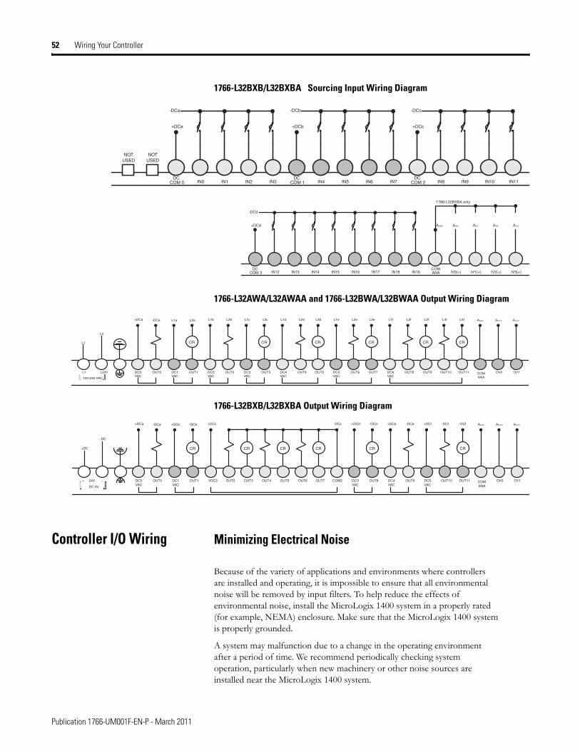
52 Wiring Your Controller
1766-L32BXB/L32BXBA Sourcing Input Wiring Diagram
1766-L32AWA/L32AWAA and 1766-L32BWA/L32BWAA Output Wiring Diagram
1766-L32BXB/L32BXBA Output Wiring Diagram
Controller I/O Wiring Minimizing Electrical Noise
Because of the variety of applications and environments where controllers are installed and operating, it is impossible to ensure that all environmental noise will be removed by input filters. To help reduce the effects of environmental noise, install the MicroLogix 1400 system in a properly rated (for example, NEMA) enclosure. Make sure that the MicroLogix 1400 system is properly grounded.
A system may malfunction due to a change in the operating environment after a period of time. We recommend periodically checking system operation, particularly when new machinery or other noise sources are installed near the MicroLogix 1400 system.
DCCOM 0
+DCa
-DCa
IN0 IN1 IN2 IN3DC
COM 1
+DCb
-DCb
IN4 IN5 IN6 IN7DC
COM 2
+DCc
-DCc
IN8 IN9 IN10 IN11
NOTUSED
NOTUSED
DCCOM 3
+DCd
-DCd
IN12 IN13 IN14 IN15 IN17 IN18 IN19IN16COMANA
AGND AIN0
IV0(+) IV1(+) IV2(+) IV3(+)
AIN1 AIN2 AIN3
1766-L32BXBA only
L1
L2
-DCa L1a L2a AOUT0 AOUT1AGND
L1 L2/N
100-240 VAC
DC0VAC
OUT0 DC1VAC
OUT1 DC2VAC
OUT2 DC3VAC
OUT3 DC4VAC
OUT4 OUT5 DC5VAC
OUT6 OUT7 DC6VAC
OUT8 OUT9 OUT10 OUT11 COMANA
OV0 OV1
+DCa L1b L2b L1c L2c L1d L2d L3d L1e L2e L3e L1f L2f L3f L4f L5f
CR CR CR CR CR CR
+DC
-DC
-DCa +DCb -DCb AOUT0 AOUT1AGND
+ 24V -
DC IN
DC0VAC
OUT0 DC1VAC
OUT1 VDC2 OUT2 OUT3 OUT4 OUT5 OUT6 OUT7 COM2 DC3VAC
OUT8 DC4VAC
OUT9 DC5VAC
OUT10 OUT11 COMANA
OV0 OV1
+DCa +DCc -DCc +DCd -DCd +DCe -DCe +DCf -DCf -DCf
CR CR CR CR CRCR
Publication 1766-UM001F-EN-P - March 2011
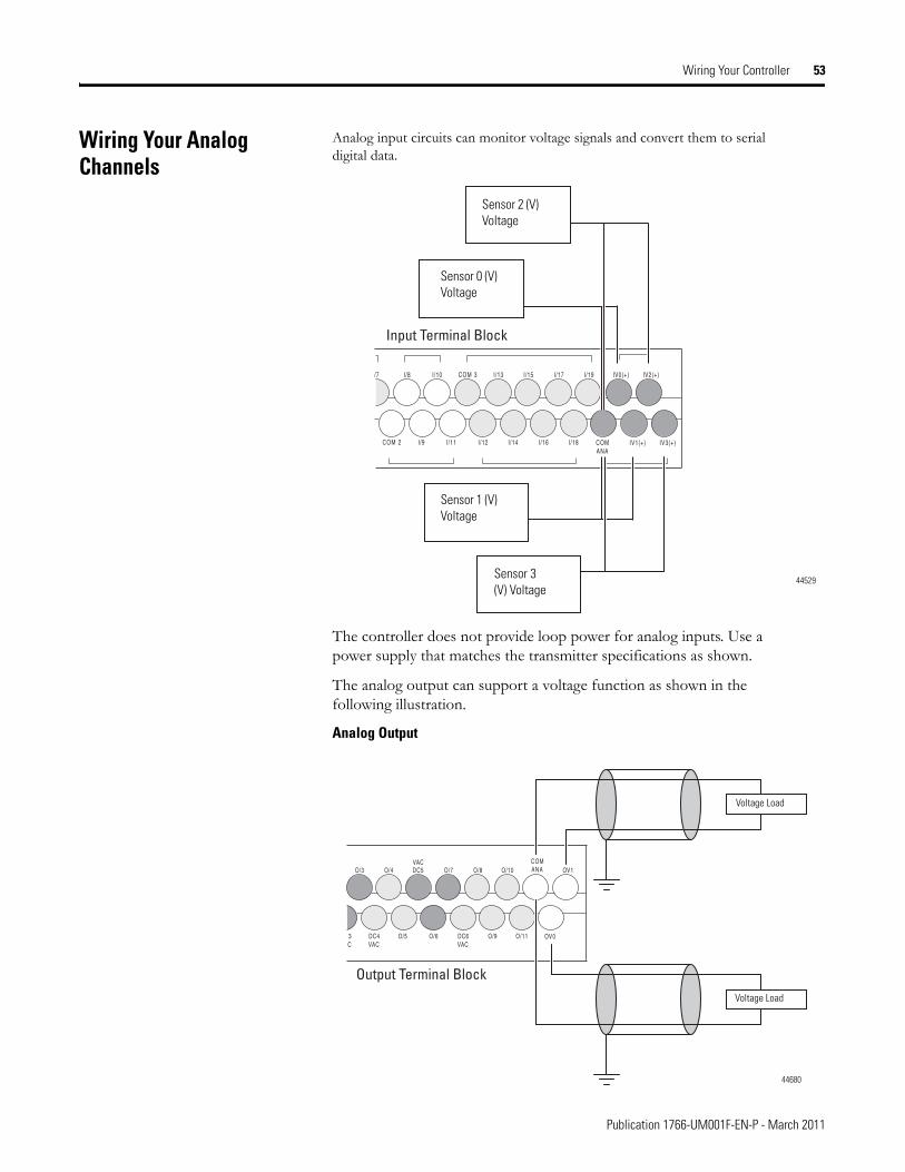
Wiring Your Controller 53
Wiring Your Analog Channels
Analog input circuits can monitor voltage signals and convert them to serial digital data.
The controller does not provide loop power for analog inputs. Use a power supply that matches the transmitter specifications as shown.
The analog output can support a voltage function as shown in the following illustration.
Analog Output
IV0(+) IV2(+)
IV1(+) IV3(+)
/7
COM 2
I/8 I/10
I/9 I/11
COM 3 I/13 I/15 I/17 I/19
I/12 I/14 I/16 I/18 COMANA
Input Terminal Block
Sensor 2 (V) Voltage
44529Sensor 3 (V) Voltage
Sensor 0 (V) Voltage
Sensor 1 (V) Voltage
OV1O/3 O/4
O/5
O/7 O/8 O/10
O/6 O/9 O/11 OV03C
DC4VAC
DC6VAC
COMANADC5
VAC
Output Terminal Block
Voltage Load
44680
Voltage Load
Publication 1766-UM001F-EN-P - March 2011
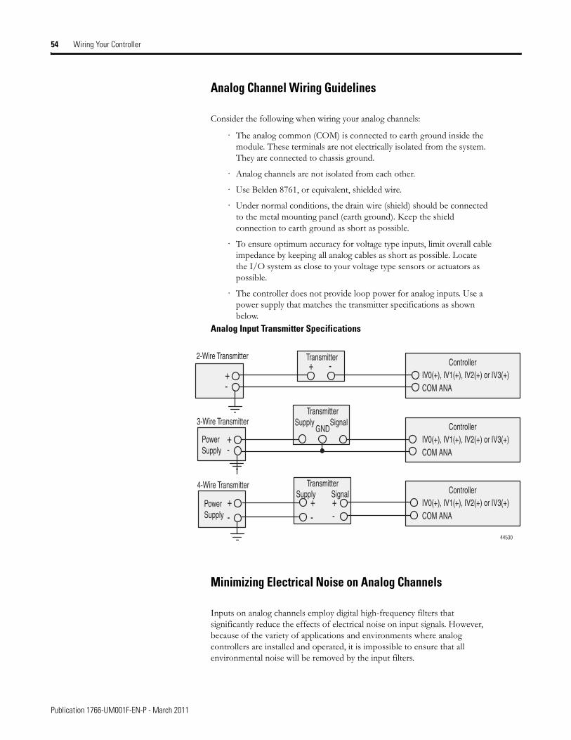
54 Wiring Your Controller
Analog Channel Wiring Guidelines
Consider the following when wiring your analog channels:
· The analog common (COM) is connected to earth ground inside the module. These terminals are not electrically isolated from the system. They are connected to chassis ground.
· Analog channels are not isolated from each other.
· Use Belden 8761, or equivalent, shielded wire.
· Under normal conditions, the drain wire (shield) should be connected to the metal mounting panel (earth ground). Keep the shield connection to earth ground as short as possible.
· To ensure optimum accuracy for voltage type inputs, limit overall cable impedance by keeping all analog cables as short as possible. Locate the I/O system as close to your voltage type sensors or actuators as possible.
· The controller does not provide loop power for analog inputs. Use a power supply that matches the transmitter specifications as shown below.
Analog Input Transmitter Specifications
Minimizing Electrical Noise on Analog Channels
Inputs on analog channels employ digital high-frequency filters that significantly reduce the effects of electrical noise on input signals. However, because of the variety of applications and environments where analog controllers are installed and operated, it is impossible to ensure that all environmental noise will be removed by the input filters.
IV0(+), IV1(+), IV2(+) or IV3(+)Controller
IV0(+), IV1(+), IV2(+) or IV3(+)Controller
+ -
+-
+-
IV0(+), IV1(+), IV2(+) or IV3(+)COM ANA
Controller
+-
+-
GND+- COM ANA
COM ANA
2-Wire Transmitter
3-Wire Transmitter
4-Wire Transmitter
Transmitter
Transmitter
TransmitterSupply Signal
Supply Signal
PowerSupply
PowerSupply
44530
Publication 1766-UM001F-EN-P - March 2011
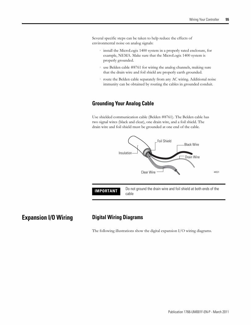
Wiring Your Controller 55
Several specific steps can be taken to help reduce the effects of environmental noise on analog signals:
· install the MicroLogix 1400 system in a properly rated enclosure, for example, NEMA. Make sure that the MicroLogix 1400 system is properly grounded.
· use Belden cable #8761 for wiring the analog channels, making sure that the drain wire and foil shield are properly earth grounded.
· route the Belden cable separately from any AC wiring. Additional noise immunity can be obtained by routing the cables in grounded conduit.
Grounding Your Analog Cable
Use shielded communication cable (Belden #8761). The Belden cable has two signal wires (black and clear), one drain wire, and a foil shield. The drain wire and foil shield must be grounded at one end of the cable.
Expansion I/O Wiring Digital Wiring Diagrams
The following illustrations show the digital expansion I/O wiring diagrams.
IMPORTANT Do not ground the drain wire and foil shield at both ends of the cable
Foil ShieldBlack Wire
Drain Wire
Clear Wire
Insulation
44531
Publication 1766-UM001F-EN-P - March 2011
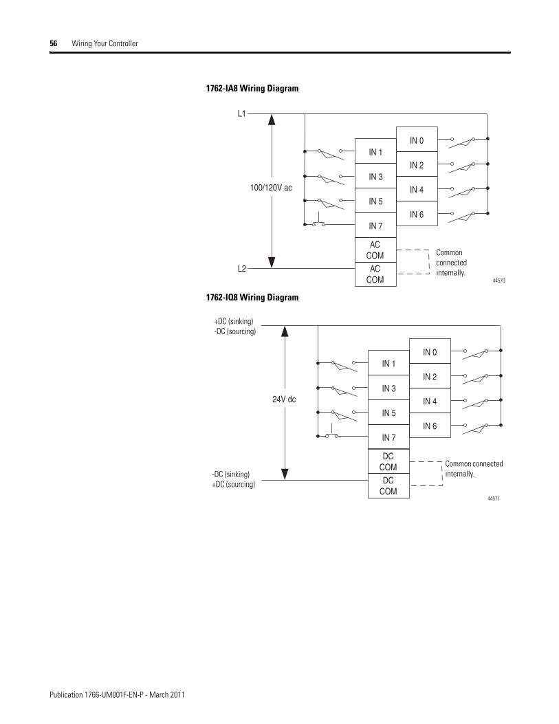
56 Wiring Your Controller
1762-IA8 Wiring Diagram
1762-IQ8 Wiring Diagram
IN 7
IN 5
IN 3
IN 1
ACCOM
IN 6
IN 4
IN 2
IN 0
L1
L2
100/120V ac
ACCOM Common
connected internally.
44570
IN 7
IN 5
IN 3
IN 1
DCCOM
IN 6
IN 4
IN 2
IN 0
24V dc
DCCOM Common connected
internally.-DC (sinking)+DC (sourcing)
+DC (sinking)-DC (sourcing)
44571
Publication 1766-UM001F-EN-P - March 2011
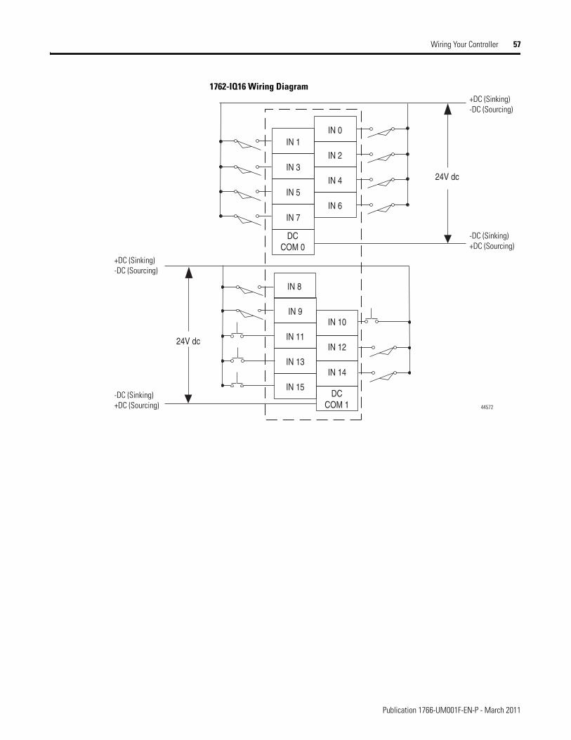
Wiring Your Controller 57
1762-IQ16 Wiring Diagram
IN 7
IN 5
IN 3
IN 1
IN 6
IN 4
IN 2
IN 0
24V dc
IN 15
IN 13
IN 11
IN 9
DCCOM 0
IN 14
IN 12
IN 10
IN 8
24V dc
DCCOM 1
+DC (Sinking) -DC (Sourcing)
-DC (Sinking)+DC (Sourcing)
+DC (Sinking)-DC (Sourcing)
-DC (Sinking)+DC (Sourcing) 44572
Publication 1766-UM001F-EN-P - March 2011
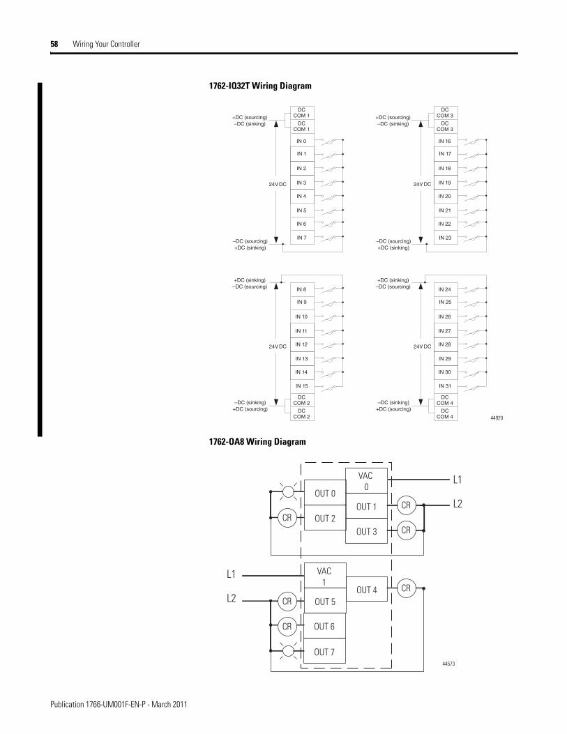
58 Wiring Your Controller
1762-IQ32T Wiring Diagram
1762-OA8 Wiring Diagram
44920
OUT 5
VAC1
OUT 2
OUT 0
OUT 7
OUT 4
OUT 3
OUT 1
VAC 0
OUT 6
CR
CR
CR
CR
CR
CRL2
L1
L2
L1
44573
Publication 1766-UM001F-EN-P - March 2011
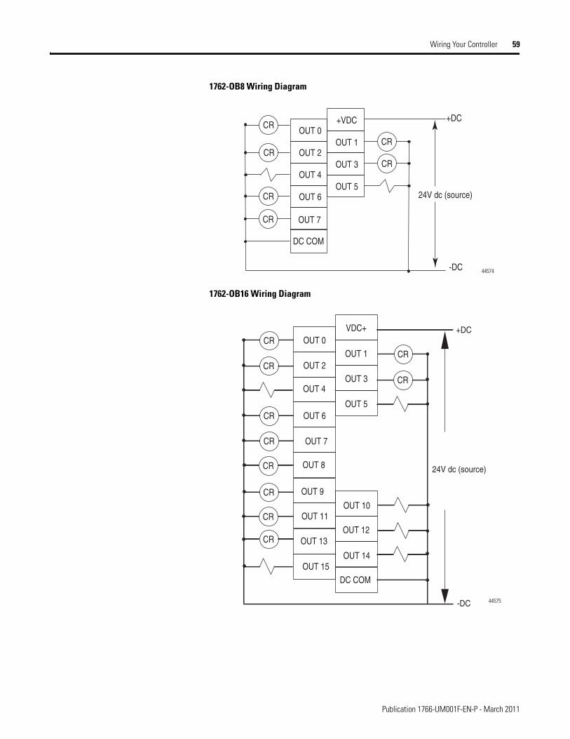
Wiring Your Controller 59
1762-OB8 Wiring Diagram
1762-OB16 Wiring Diagram
+DC
24V dc (source)
-DC
OUT 6
OUT 4
OUT 2
OUT 0
OUT 7
OUT 5
OUT 3
OUT 1
+VDC
CR
CR
CR
CR
CR
CR
DC COM
44574
OUT 6
OUT 2
OUT 0
OUT 10
OUT 5
OUT 7
OUT 9
OUT 11
OUT 13
OUT 15OUT 14
OUT 3
OUT 1
VDC+
OUT 8
OUT 12
CR
CR
CR
CR
CR
CR
CR
CR
CR
CR
OUT 4
DC COM
24V dc (source)
+DC
-DC 44575
Publication 1766-UM001F-EN-P - March 2011
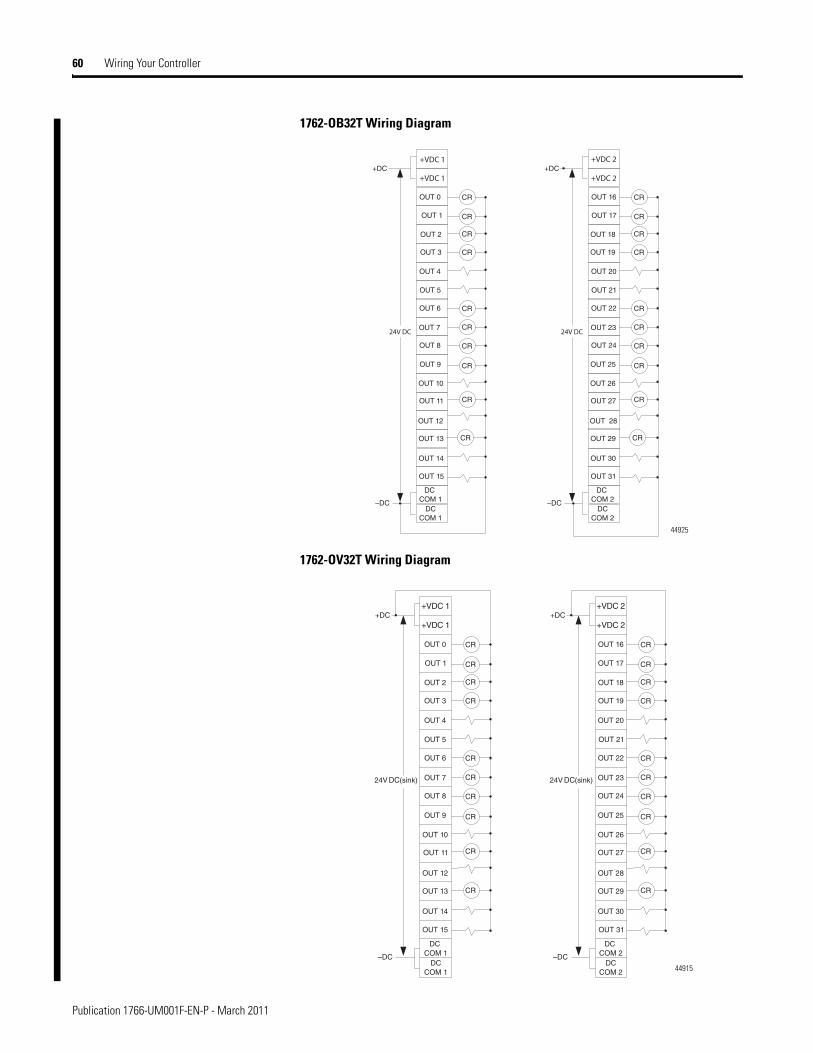
60 Wiring Your Controller
1762-OB32T Wiring Diagram
1762-OV32T Wiring Diagram
44925
44915
Publication 1766-UM001F-EN-P - March 2011
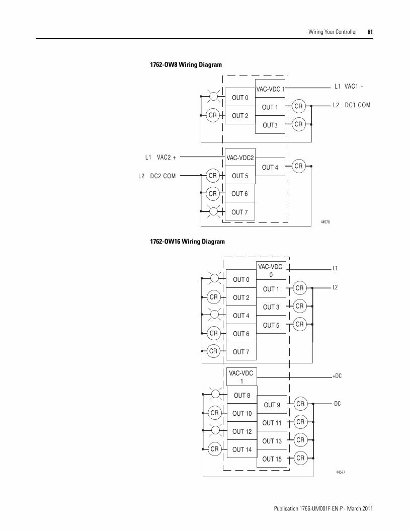
Wiring Your Controller 61
1762-OW8 Wiring Diagram
1762-OW16 Wiring Diagram
OUT 5
VAC-VDC2
OUT 2
OUT 0
OUT 7
OUT 4
OUT3
OUT 1
VAC-VDC 1
OUT 6
CR
CR
CR
CR
CR
CR
L1 VAC1 +
L2 DC1 COM
L1 VAC2 +
L2 DC2 COM
44576
OUT 2
OUT 0
OUT 3
OUT 1
VAC-VDC 0
CR
CRCR
OUT 6
OUT 4
OUT 7
OUT 5 CRCR
CR
OUT 10
OUT 8
OUT 11
OUT 9
VAC-VDC 1
CR
CRCR
OUT 14
OUT 12
OUT 15
OUT 13 CR
CRCR
L1
L2
+DC
-DC
44577
Publication 1766-UM001F-EN-P - March 2011
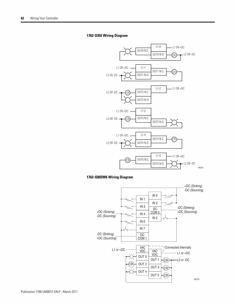
62 Wiring Your Controller
1762-OX6I Wiring Diagram
1762-IQ8OW6 Wiring Diagram
L1-0
L1-1
L1-2
L1-3
L1-4
L1-5
OUT0 N.C.OUT0 N.O.
OUT1 N.C.OUT1 N.O.
OUT2 N.C.
OUT2 N.O.
OUT3 N.O.OUT3 N.C.
OUT4 N.C.OUT4 N.O.
OUT5 N.C.OUT5 N.O.
CR
CR
CR
CR
CR
CRL1 OR +DC
L1 OR +DC
L1 OR +DC
L1 OR +DC
L1 OR +DC
L1 OR +DC
L2 OR -DC
L2 OR -DC
L2 OR -DC
L2 OR -DC
L2 OR -DC
L2 OR -DC
44578
IN 6
IN 4
IN 3
IN 1
IN 5
IN 2
IN 0
OUT 4
OUT 2
OUT 0
VACVDC VAC
VDC
DCCOM 1
OUT 3
OUT 1
IN 7
L1 or +DCL1 or +DC
-DC (Sinking)+DC (Sourcing)
Connected Internally
+DC (Sinking)-DC (Sourcing)
L2 or -DC
OUT 5
+DC (Sinking)-DC (Sourcing)
-DC (Sinking)+DC (Sourcing)
DCCOM 0
CR
CR
CRCR
44579
Publication 1766-UM001F-EN-P - March 2011
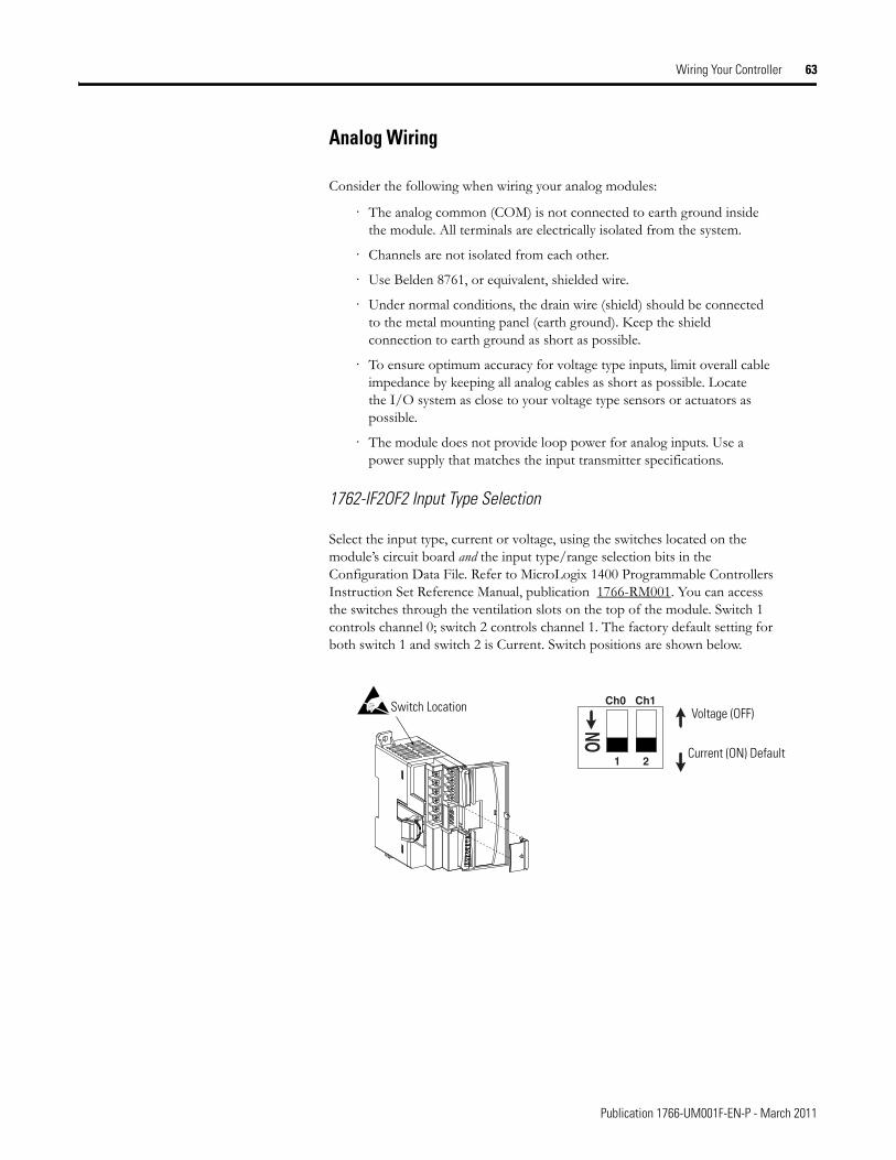
Wiring Your Controller 63
Analog Wiring
Consider the following when wiring your analog modules:
· The analog common (COM) is not connected to earth ground inside the module. All terminals are electrically isolated from the system.
· Channels are not isolated from each other.
· Use Belden 8761, or equivalent, shielded wire.
· Under normal conditions, the drain wire (shield) should be connected to the metal mounting panel (earth ground). Keep the shield connection to earth ground as short as possible.
· To ensure optimum accuracy for voltage type inputs, limit overall cable impedance by keeping all analog cables as short as possible. Locate the I/O system as close to your voltage type sensors or actuators as possible.
· The module does not provide loop power for analog inputs. Use a power supply that matches the input transmitter specifications.
1762-IF2OF2 Input Type Selection
Select the input type, current or voltage, using the switches located on the module’s circuit board and the input type/range selection bits in the Configuration Data File. Refer to MicroLogix 1400 Programmable Controllers Instruction Set Reference Manual, publication 1766-RM001. You can access the switches through the ventilation slots on the top of the module. Switch 1 controls channel 0; switch 2 controls channel 1. The factory default setting for both switch 1 and switch 2 is Current. Switch positions are shown below.
1
ON
2
Ch0 Ch1
Current (ON) Default
Voltage (OFF)Switch Location
Publication 1766-UM001F-EN-P - March 2011
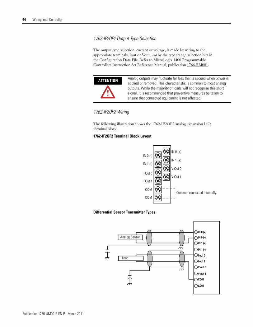
64 Wiring Your Controller
1762-IF2OF2 Output Type Selection
The output type selection, current or voltage, is made by wiring to the appropriate terminals, Iout or Vout, and by the type/range selection bits in the Configuration Data File. Refer to MicroLogix 1400 Programmable Controllers Instruction Set Reference Manual, publication 1766-RM001.
1762-IF2OF2 Wiring
The following illustration shows the 1762-IF2OF2 analog expansion I/O terminal block.
1762-IF2OF2 Terminal Block Layout
Differential Sensor Transmitter Types
ATTENTION Analog outputs may fluctuate for less than a second when power is applied or removed. This characteristic is common to most analog outputs. While the majority of loads will not recognize this short signal, it is recommended that preventive measures be taken to ensure that connected equipment is not affected.
V Out 1
V Out 0
IN 1 (+)
IN 0 (+)
I Out 1
I Out 0
IN 1 (-)
IN 0 (-)
COM
COMCommon connected internally.
IN 0 (+)
IN 0 (-)
V out 0
V out 1
I out 0
I out 1
COM
IN 1 (-)
IN 1 (+)
COM
Analog Sensor
Load
Publication 1766-UM001F-EN-P - March 2011
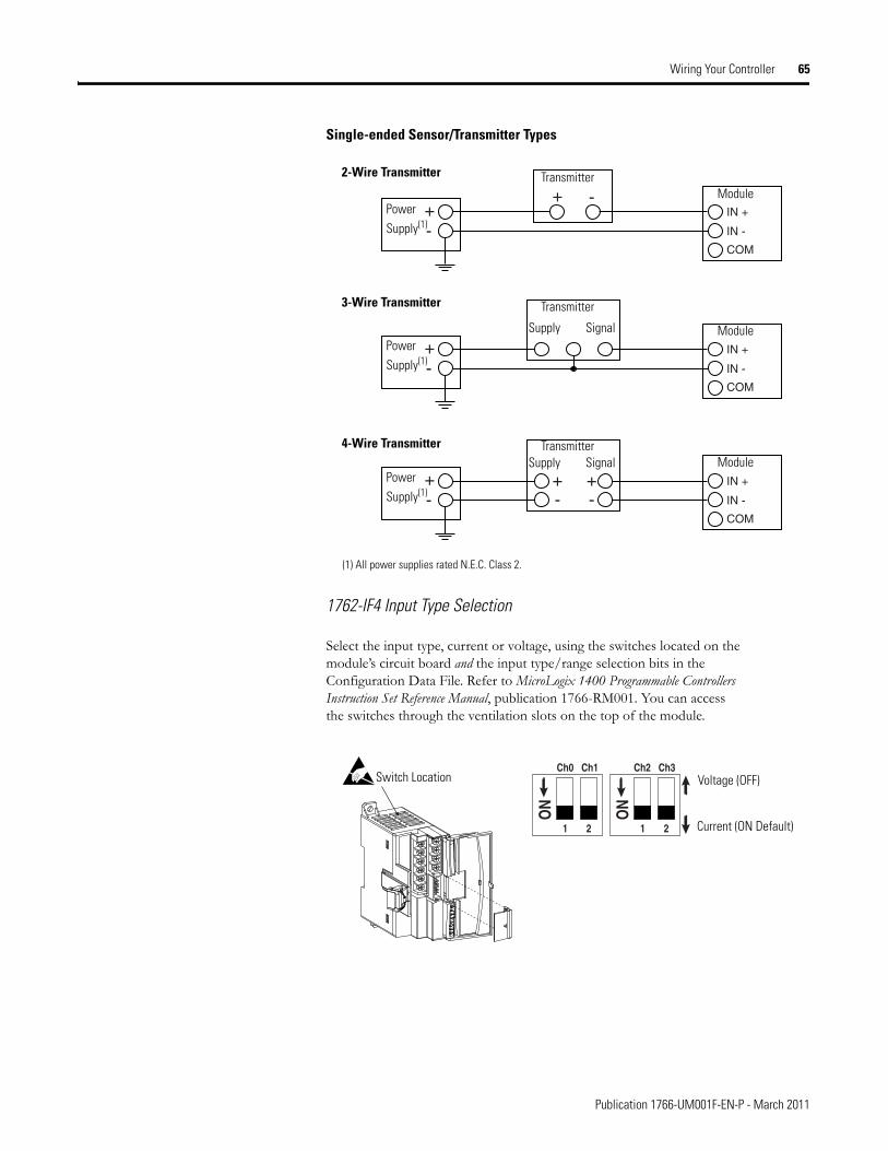
Wiring Your Controller 65
Single-ended Sensor/Transmitter Types
1762-IF4 Input Type Selection
Select the input type, current or voltage, using the switches located on the module’s circuit board and the input type/range selection bits in the Configuration Data File. Refer to MicroLogix 1400 Programmable Controllers Instruction Set Reference Manual, publication 1766-RM001. You can access the switches through the ventilation slots on the top of the module.
++
-
-
+-
+-
IN +
IN -
COM
+-
IN +
IN -
COM
+-
IN +
IN -
COM
Power Supply(1)
Transmitter
Transmitter
Transmitter
Supply
Supply
Signal
Signal
Module
Module
Module
2-Wire Transmitter
3-Wire Transmitter
4-Wire Transmitter
Power Supply(1)
Power Supply(1)
(1) All power supplies rated N.E.C. Class 2.
1
Ch0 Ch1 Ch2 Ch3
ON
2 1
ON
2 Current (ON Default)
Voltage (OFF)Switch Location
Publication 1766-UM001F-EN-P - March 2011
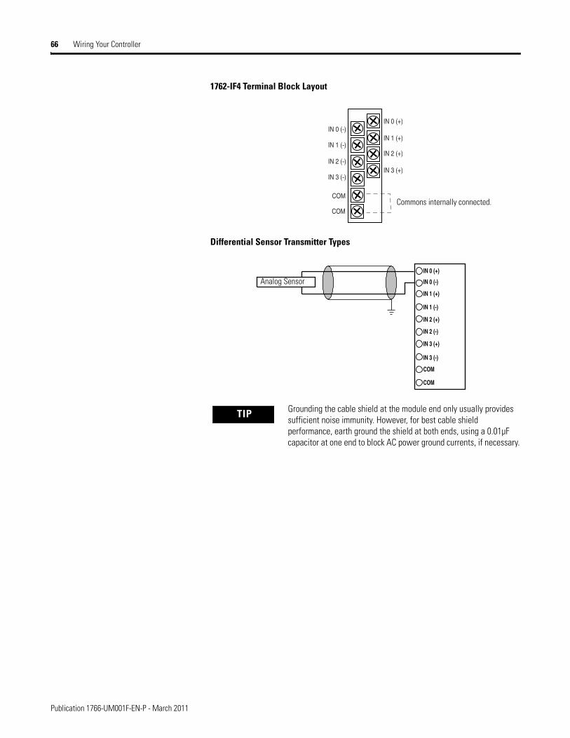
66 Wiring Your Controller
1762-IF4 Terminal Block Layout
Differential Sensor Transmitter Types
TIP Grounding the cable shield at the module end only usually provides sufficient noise immunity. However, for best cable shield performance, earth ground the shield at both ends, using a 0.01µF capacitor at one end to block AC power ground currents, if necessary.
IN 1 (+)
IN 0 (+)
IN 1 (-)
IN 0 (-)
IN 3 (+)
IN 2 (+)
IN 3 (-)
IN 2 (-)
COM
COMCommons internally connected.
IN 0 (+)
IN 0 (-)
IN 3 (+)
IN 3 (-)
IN 2 (+)
IN 2 (-)
COM
IN 1 (-)
IN 1 (+)
COM
Analog Sensor
Publication 1766-UM001F-EN-P - March 2011
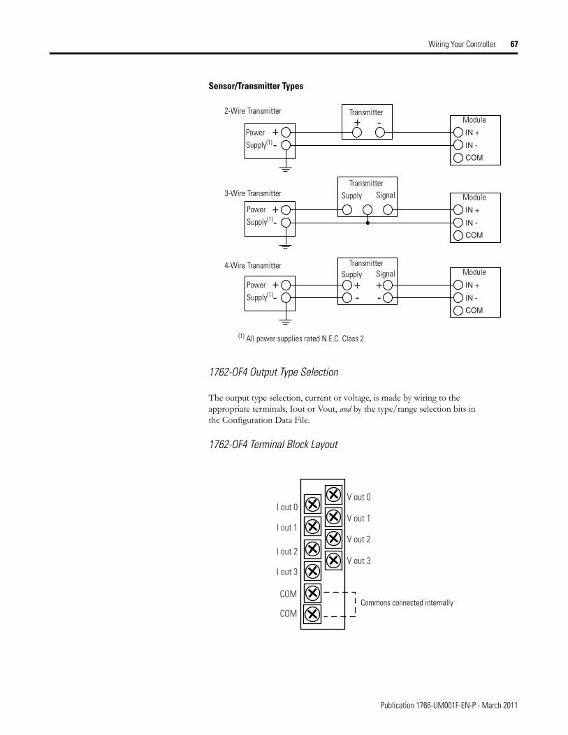
Wiring Your Controller 67
Sensor/Transmitter Types
1762-OF4 Output Type Selection
The output type selection, current or voltage, is made by wiring to the appropriate terminals, Iout or Vout, and by the type/range selection bits in the Configuration Data File.
1762-OF4 Terminal Block Layout
++
-
-
+-
+-
IN +
IN -
COM
+-
IN +
IN -
COM
+-
IN +
IN -
COM
Power Supply(1)
Power Supply(1)
Power Supply(1)
Transmitter
Transmitter
Transmitter
Module
Supply Signal
2-Wire Transmitter
3-Wire Transmitter
4-Wire Transmitter
(1) All power supplies rated N.E.C. Class 2.
Supply Signal Module
Module
V out 3
V out 2
V out 1
V out 0
I out 3
I out 2
I out 1
I out 0
COM
COMCommons connected internally
Publication 1766-UM001F-EN-P - March 2011
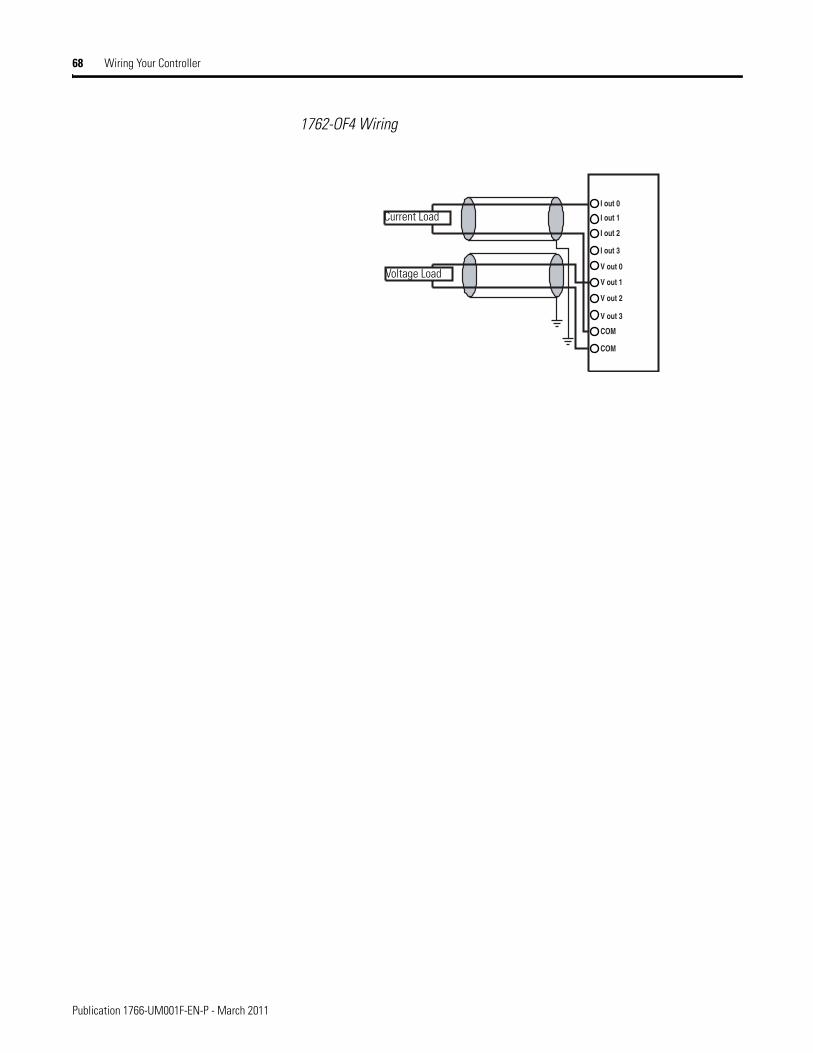
68 Wiring Your Controller
1762-OF4 Wiring
I out 0
I out 1
V out 2
V out 3
V out 0
V out 1
COM
I out 3
I out 2
COM
Current Load
Voltage Load
Publication 1766-UM001F-EN-P - March 2011

Wiring Your Controller 69
Notes:
Publication 1766-UM001F-EN-P - March 2011

70 Wiring Your Controller
Publication 1766-UM001F-EN-P - March 2011
Chapter 4
Communication Connections
This chapter describes how to communicate with your control system. The method you use and cabling required to connect your controller depends on what type of system you are employing. This chapter also describes how the controller establishes communication with the appropriate network. Topics include:
• supported communication protocols
• default communication configurations
• using communications toggle functionality
• connecting to RS-232 port
• connecting to RS-485 network
• connecting to AIC+
• connecting to DeviceNet
• connecting to Ethernet
The MicroLogix 1400 controllers provide three communication channels, an isolated RS-232/485 communication port (Channel 0), an Ethernet port (Channel 1) and a non-isolated RS-232 communication port (Channel 2).
Supported Communication Protocols
MicroLogix 1400 controllers support the following communication protocols from the primary RS-232/485 communication channel 0 and the RS-232 communication channel 2:
• DH-485
• DF1 Full-Duplex
• DF1 Half-Duplex Master and Slave
• DF1 Radio Modem
• Modbus RTU Master and Slave
• ASCII
• DNP3 Slave
The Ethernet communication channel, Channel 1, allows your controller to be connected to a local area network for various devices providing 10 Mbps/100 Mbps transfer rate. MicroLogix 1400 controllers support Ethernet/IP with CIP explicit messaging (message exchange), BOOTP/DHCP Client, HTTP Server, SMTP Client, DNS Client, SNMP Server, Socket Interface with CIP Generic messaging, Modbus TCP Client/Server and DNP3 over IP. MicroLogix 1400 controllers do not support Ethernet I/O master capability through CIP implicit messaging (real-time I/O messaging).
71 Publication 1766-UM001F-EN-P - March 2011
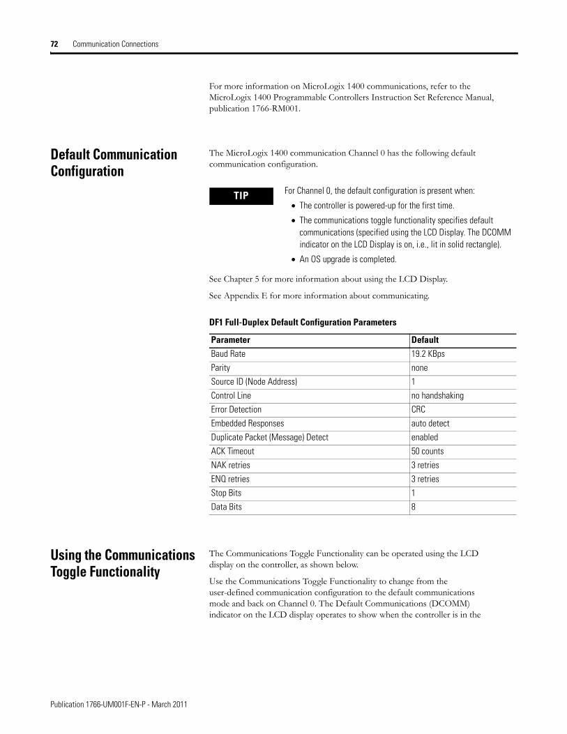
72 Communication Connections
For more information on MicroLogix 1400 communications, refer to the MicroLogix 1400 Programmable Controllers Instruction Set Reference Manual, publication 1766-RM001.
Default Communication Configuration
The MicroLogix 1400 communication Channel 0 has the following default communication configuration.
See Chapter 5 for more information about using the LCD Display.
See Appendix E for more information about communicating.
Using the Communications Toggle Functionality
The Communications Toggle Functionality can be operated using the LCD display on the controller, as shown below.
Use the Communications Toggle Functionality to change from the user-defined communication configuration to the default communications mode and back on Channel 0. The Default Communications (DCOMM) indicator on the LCD display operates to show when the controller is in the
TIP For Channel 0, the default configuration is present when:
• The controller is powered-up for the first time.
• The communications toggle functionality specifies default communications (specified using the LCD Display. The DCOMM indicator on the LCD Display is on, i.e., lit in solid rectangle).
• An OS upgrade is completed.
DF1 Full-Duplex Default Configuration Parameters
Parameter DefaultBaud Rate 19.2 KBps
Parity none
Source ID (Node Address) 1
Control Line no handshaking
Error Detection CRC
Embedded Responses auto detect
Duplicate Packet (Message) Detect enabled
ACK Timeout 50 counts
NAK retries 3 retries
ENQ retries 3 retries
Stop Bits 1
Data Bits 8
Publication 1766-UM001F-EN-P - March 2011
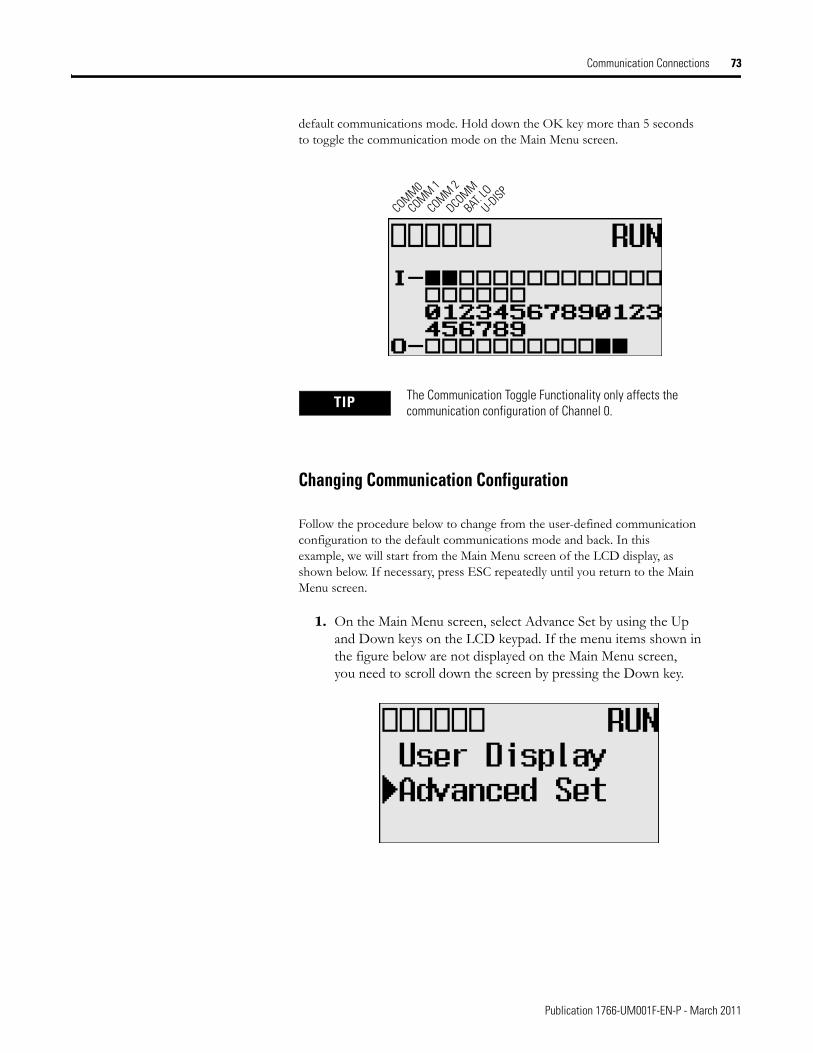
Communication Connections 73
default communications mode. Hold down the OK key more than 5 seconds to toggle the communication mode on the Main Menu screen.
Changing Communication Configuration
Follow the procedure below to change from the user-defined communication configuration to the default communications mode and back. In this example, we will start from the Main Menu screen of the LCD display, as shown below. If necessary, press ESC repeatedly until you return to the Main Menu screen.
1. On the Main Menu screen, select Advance Set by using the Up and Down keys on the LCD keypad. If the menu items shown in the figure below are not displayed on the Main Menu screen, you need to scroll down the screen by pressing the Down key.
TIP The Communication Toggle Functionality only affects the communication configuration of Channel 0.
COMM0
COMM 1
DCOMM
BAT. LO
U-DISPCOMM 2
Publication 1766-UM001F-EN-P - March 2011
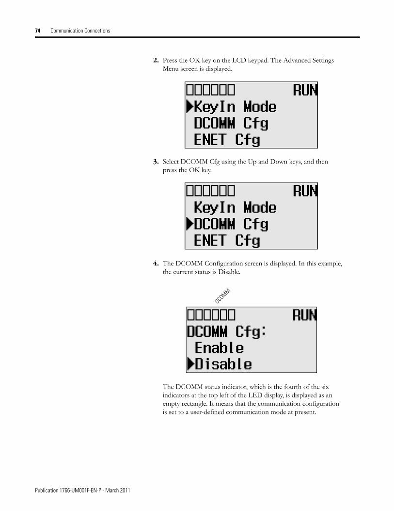
74 Communication Connections
2. Press the OK key on the LCD keypad. The Advanced Settings Menu screen is displayed.
3. Select DCOMM Cfg using the Up and Down keys, and then press the OK key.
4. The DCOMM Configuration screen is displayed. In this example, the current status is Disable.
The DCOMM status indicator, which is the fourth of the six indicators at the top left of the LED display, is displayed as an empty rectangle. It means that the communication configuration is set to a user-defined communication mode at present.
DCOMM
Publication 1766-UM001F-EN-P - March 2011
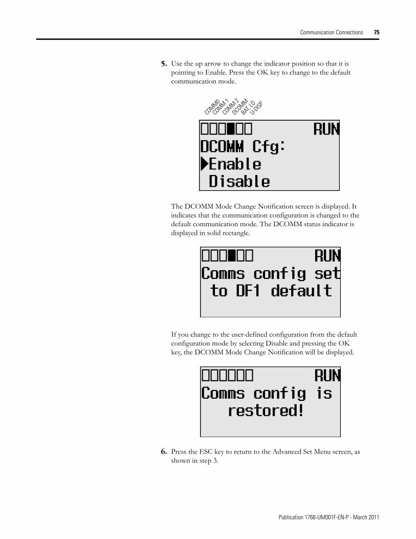
Communication Connections 75
5. Use the up arrow to change the indicator position so that it is pointing to Enable. Press the OK key to change to the default communication mode.
The DCOMM Mode Change Notification screen is displayed. It indicates that the communication configuration is changed to the default communication mode. The DCOMM status indicator is displayed in solid rectangle.
If you change to the user-defined configuration from the default configuration mode by selecting Disable and pressing the OK key, the DCOMM Mode Change Notification will be displayed.
6. Press the ESC key to return to the Advanced Set Menu screen, as shown in step 3.
COMM0
COMM 1
DCOMM
BAT. LO
U-DISPCOMM 2
Publication 1766-UM001F-EN-P - March 2011
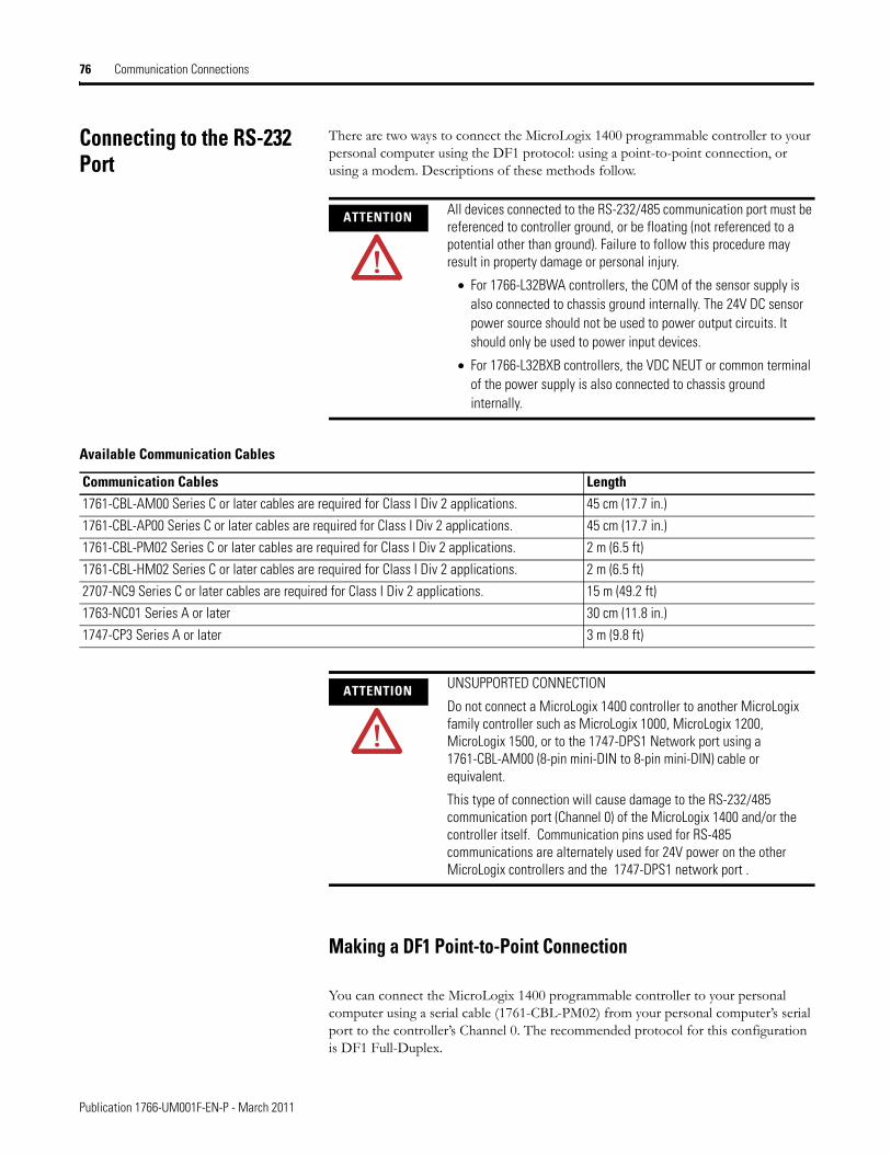
76 Communication Connections
Connecting to the RS-232 Port
There are two ways to connect the MicroLogix 1400 programmable controller to your personal computer using the DF1 protocol: using a point-to-point connection, or using a modem. Descriptions of these methods follow.
Making a DF1 Point-to-Point Connection
You can connect the MicroLogix 1400 programmable controller to your personal computer using a serial cable (1761-CBL-PM02) from your personal computer’s serial port to the controller’s Channel 0. The recommended protocol for this configuration is DF1 Full-Duplex.
ATTENTION All devices connected to the RS-232/485 communication port must be referenced to controller ground, or be floating (not referenced to a potential other than ground). Failure to follow this procedure may result in property damage or personal injury.
• For 1766-L32BWA controllers, the COM of the sensor supply is also connected to chassis ground internally. The 24V DC sensor power source should not be used to power output circuits. It should only be used to power input devices.
• For 1766-L32BXB controllers, the VDC NEUT or common terminal of the power supply is also connected to chassis ground internally.
Available Communication Cables
Communication Cables Length1761-CBL-AM00 Series C or later cables are required for Class I Div 2 applications. 45 cm (17.7 in.)
1761-CBL-AP00 Series C or later cables are required for Class I Div 2 applications. 45 cm (17.7 in.)
1761-CBL-PM02 Series C or later cables are required for Class I Div 2 applications. 2 m (6.5 ft)
1761-CBL-HM02 Series C or later cables are required for Class I Div 2 applications. 2 m (6.5 ft)
2707-NC9 Series C or later cables are required for Class I Div 2 applications. 15 m (49.2 ft)
1763-NC01 Series A or later 30 cm (11.8 in.)
1747-CP3 Series A or later 3 m (9.8 ft)
ATTENTION UNSUPPORTED CONNECTION
Do not connect a MicroLogix 1400 controller to another MicroLogix family controller such as MicroLogix 1000, MicroLogix 1200, MicroLogix 1500, or to the 1747-DPS1 Network port using a 1761-CBL-AM00 (8-pin mini-DIN to 8-pin mini-DIN) cable or equivalent.
This type of connection will cause damage to the RS-232/485 communication port (Channel 0) of the MicroLogix 1400 and/or the controller itself. Communication pins used for RS-485 communications are alternately used for 24V power on the other MicroLogix controllers and the 1747-DPS1 network port .
Publication 1766-UM001F-EN-P - March 2011
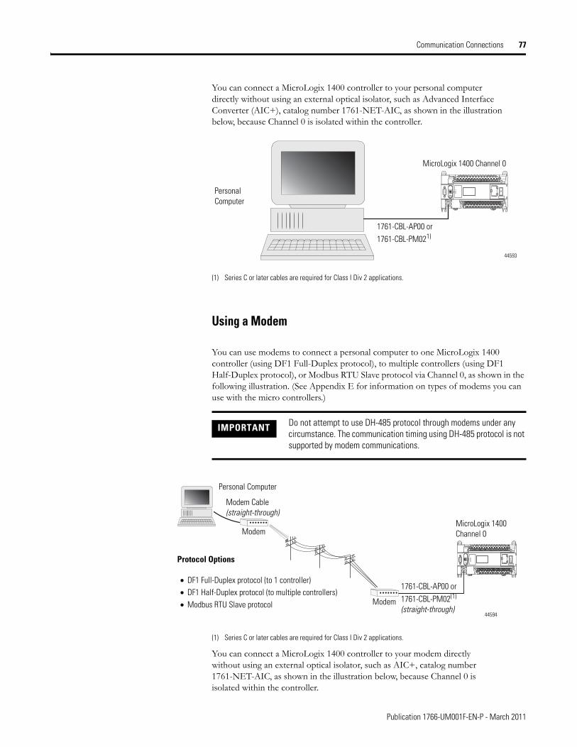
Communication Connections 77
You can connect a MicroLogix 1400 controller to your personal computer directly without using an external optical isolator, such as Advanced Interface Converter (AIC+), catalog number 1761-NET-AIC, as shown in the illustration below, because Channel 0 is isolated within the controller.
(1) Series C or later cables are required for Class I Div 2 applications.
Using a Modem
You can use modems to connect a personal computer to one MicroLogix 1400 controller (using DF1 Full-Duplex protocol), to multiple controllers (using DF1 Half-Duplex protocol), or Modbus RTU Slave protocol via Channel 0, as shown in the following illustration. (See Appendix E for information on types of modems you can use with the micro controllers.)
(1) Series C or later cables are required for Class I Div 2 applications.
You can connect a MicroLogix 1400 controller to your modem directly without using an external optical isolator, such as AIC+, catalog number 1761-NET-AIC, as shown in the illustration below, because Channel 0 is isolated within the controller.
IMPORTANT Do not attempt to use DH-485 protocol through modems under any circumstance. The communication timing using DH-485 protocol is not supported by modem communications.
MicroLogix 1400 Channel 0
Personal Computer
1761-CBL-AP00 or 1761-CBL-PM021)
44593
Modem Cable (straight-through)
Personal Computer
Modem
Modem
MicroLogix 1400 Channel 0
Protocol Options
• DF1 Full-Duplex protocol (to 1 controller)• DF1 Half-Duplex protocol (to multiple controllers)• Modbus RTU Slave protocol
1761-CBL-AP00 or 1761-CBL-PM02(1)
(straight-through)44594
Publication 1766-UM001F-EN-P - March 2011
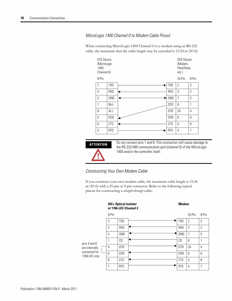
78 Communication Connections
MicroLogix 1400 Channel 0 to Modem Cable Pinout
When connecting MicroLogix 1400 Channel 0 to a modem using an RS-232 cable, the maximum that the cable length may be extended is 15.24 m (50 ft).
Constructing Your Own Modem Cable
If you construct your own modem cable, the maximum cable length is 15.24 m (50 ft) with a 25-pin or 9-pin connector. Refer to the following typical pinout for constructing a straight-through cable:
ATTENTION Do not connect pins 1 and 8. This connection will cause damage to the RS-232/485 communication port (channel 0) of the MicroLogix 1400 and/or the controller itself.
DTE Device(MicroLogix 1400 Channel 0)
DCE Device (Modem, PanelView, etc.)
8-Pin 25-Pin 9-Pin
7 TXD TXD 2 3
4 RXD RXD 3 2
2 GND GND 7 5
1 B(+) DCD 8 1
8 A(-) DTR 20 4
5 DCD DSR 6 6
6 CTS CTS 5 8
3 RTS RTS 4 7
AIC+ Optical Isolatoror 1766-LEC Channel 2
Modem
9-Pin 25-Pin 9-Pin
3 TXD TXD 2 3
2 RXD RXD 3 2
5 GND GND 7 5
1 CD CD 8 1
4 DTR DTR 20 4
6 DSR DSR 6 6
8 CTS CTS 5 8
7 RTS RTS 4 7
pins 4 and 6 are internally connected for 1766-LEC only
Publication 1766-UM001F-EN-P - March 2011
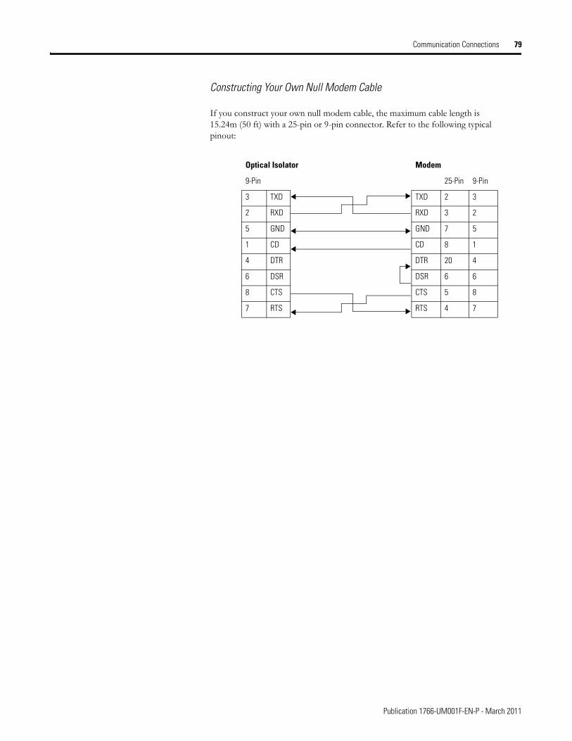
Communication Connections 79
Constructing Your Own Null Modem Cable
If you construct your own null modem cable, the maximum cable length is 15.24m (50 ft) with a 25-pin or 9-pin connector. Refer to the following typical pinout:
Optical Isolator Modem
9-Pin 25-Pin 9-Pin
3 TXD TXD 2 3
2 RXD RXD 3 2
5 GND GND 7 5
1 CD CD 8 1
4 DTR DTR 20 4
6 DSR DSR 6 6
8 CTS CTS 5 8
7 RTS RTS 4 7
Publication 1766-UM001F-EN-P - March 2011
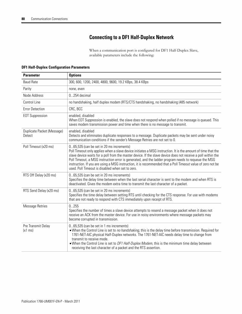
80 Communication Connections
Connecting to a DF1 Half-Duplex Network
When a communication port is configured for DF1 Half-Duplex Slave, available parameters include the following:
DF1 Half-Duplex Configuration Parameters
Parameter Options
Baud Rate 300, 600, 1200, 2400, 4800, 9600, 19.2 KBps, 38.4 KBps
Parity none, even
Node Address 0...254 decimal
Control Line no handshaking, half duplex modem (RTS/CTS handshaking, no handshaking (485 network)
Error Detection CRC, BCC
EOT Suppression enabled, disabledWhen EOT Suppression is enabled, the slave does not respond when polled if no message is queued. This saves modem transmission power and time when there is no message to transmit.
Duplicate Packet (Message) Detect
enabled, disabledDetects and eliminates duplicate responses to a message. Duplicate packets may be sent under noisy communication conditions if the sender’s Message Retries are not set to 0.
Poll Timeout (x20 ms) 0...65,535 (can be set in 20 ms increments)Poll Timeout only applies when a slave device initiates a MSG instruction. It is the amount of time that the slave device waits for a poll from the master device. If the slave device does not receive a poll within the Poll Timeout, a MSG instruction error is generated, and the ladder program needs to requeue the MSG instruction. If you are using a MSG instruction, it is recommended that a Poll Timeout value of zero not be used. Poll Timeout is disabled when set to zero.
RTS Off Delay (x20 ms) 0...65,535 (can be set in 20 ms increments)Specifies the delay time between when the last serial character is sent to the modem and when RTS is deactivated. Gives the modem extra time to transmit the last character of a packet.
RTS Send Delay (x20 ms) 0...65,535 (can be set in 20 ms increments)Specifies the time delay between setting RTS until checking for the CTS response. For use with modems that are not ready to respond with CTS immediately upon receipt of RTS.
Message Retries 0...255Specifies the number of times a slave device attempts to resend a message packet when it does not receive an ACK from the master device. For use in noisy environments where message packets may become corrupted in transmission.
Pre Transmit Delay (x1 ms)
0...65,535 (can be set in 1 ms increments)• When the Control Line is set to no handshaking, this is the delay time before transmission. Required for
1761-NET-AIC physical Half-Duplex networks. The 1761-NET-AIC needs delay time to change from transmit to receive mode.
• When the Control Line is set to DF1 Half-Duplex Modem, this is the minimum time delay between receiving the last character of a packet and the RTS assertion.
Publication 1766-UM001F-EN-P - March 2011
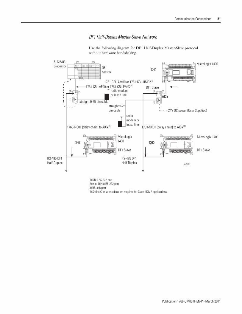
Communication Connections 81
DF1 Half-Duplex Master-Slave Network
Use the following diagram for DF1 Half-Duplex Master-Slave protocol without hardware handshaking.
(1) DB-9 RS-232 port(2) mini-DIN 8 RS-232 port(3) RS-485 port(4) Series C or later cables are required for Class I Div 2 applications.
(1)(1)
(2) (2)(3) (3)
SLC 5/03 processor
MicroLogix 1400
MicroLogix 1400MicroLogix 1400
CH0
CH0
CH0CH0
1761-CBL-AP00 or 1761-CBL-PM02(4)1761-CBL-AM00 or 1761-CBL-HM02(4)
DF1 Master
DF1 Slave
DF1 Slave
straight 9-25 pin cablestraight 9-25 pin cable
radio modem or lease line
radio modem or lease line
AIC+
RS-485 DF1 Half-Duplex
DF1 Slave
1763-NC01 (daisy chain) to AIC+(4)
AIC+
24V DC power (User Supplied)
1763-NC01 (daisy chain) to AIC+(4)
44595
RS-485 DF1 Half-Duplex
Publication 1766-UM001F-EN-P - March 2011
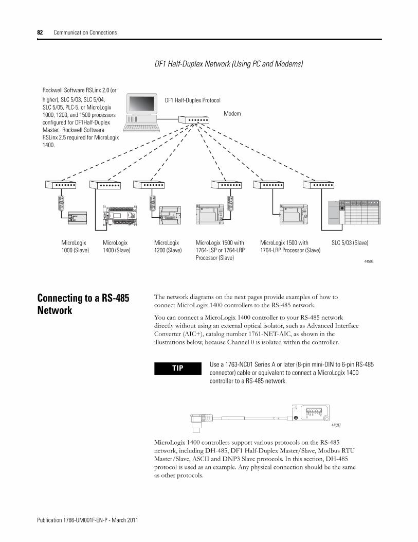
82 Communication Connections
DF1 Half-Duplex Network (Using PC and Modems)
Connecting to a RS-485 Network
The network diagrams on the next pages provide examples of how to connect MicroLogix 1400 controllers to the RS-485 network.
You can connect a MicroLogix 1400 controller to your RS-485 network directly without using an external optical isolator, such as Advanced Interface Converter (AIC+), catalog number 1761-NET-AIC, as shown in the illustrations below, because Channel 0 is isolated within the controller.
MicroLogix 1400 controllers support various protocols on the RS-485 network, including DH-485, DF1 Half-Duplex Master/Slave, Modbus RTU Master/Slave, ASCII and DNP3 Slave protocols. In this section, DH-485 protocol is used as an example. Any physical connection should be the same as other protocols.
TERM
A
B
COM
SHLD
CHS GND
TX
TX PWR
TX
DC SOURCE CABLE
EXTERNAL
TERM
A
B
COM
SHLD
CHS GND
TX
TX PWR
TX
DC SOURCE CABLE
EXTERNAL
TERM
A
B
COM
SHLD
CHS GND
TX
TX PWR
TX
DC SOURCE CABLE
EXTERNAL
Rockwell Software RSLinx 2.0 (or
higher), SLC 5/03, SLC 5/04,SLC 5/05, PLC-5, or MicroLogix 1000, 1200, and 1500 processors configured for DF1Half-Duplex Master. Rockwell Software RSLinx 2.5 required for MicroLogix 1400.
DF1 Half-Duplex Protocol
MicroLogix 1500 with 1764-LSP or 1764-LRP Processor (Slave)
SLC 5/03 (Slave)MicroLogix1000 (Slave)
MicroLogix 1500 with 1764-LRP Processor (Slave)
MicroLogix1400 (Slave)
Modem
MicroLogix1200 (Slave)
44596
TIP Use a 1763-NC01 Series A or later (8-pin mini-DIN to 6-pin RS-485 connector) cable or equivalent to connect a MicroLogix 1400 controller to a RS-485 network.
A TERM
BCOM
SHLD
CHS GND
44597
Publication 1766-UM001F-EN-P - March 2011
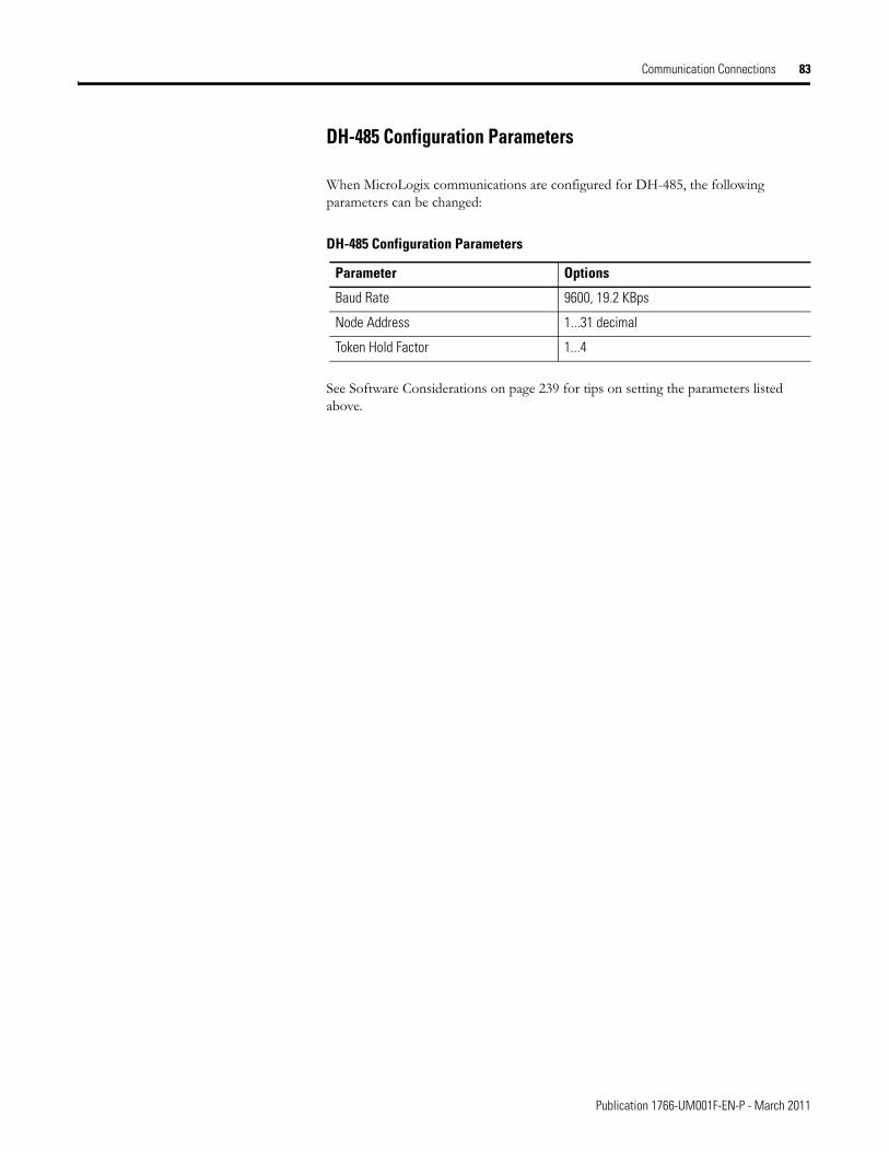
Communication Connections 83
DH-485 Configuration Parameters
When MicroLogix communications are configured for DH-485, the following parameters can be changed:
See Software Considerations on page 239 for tips on setting the parameters listed above.
DH-485 Configuration Parameters
Parameter Options
Baud Rate 9600, 19.2 KBps
Node Address 1...31 decimal
Token Hold Factor 1...4
Publication 1766-UM001F-EN-P - March 2011
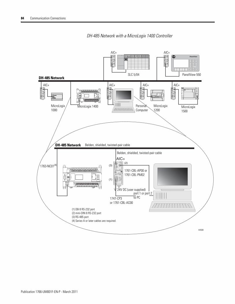
84 Communication Connections
DH-485 Network with a MicroLogix 1400 Controller
A-B PanelViewTERM
A
B
COM
SHLD
CHS GND
TX
TX PWR
TX
DC SOURCE CABLE
EXTERNAL
TERM
A
B
COM
SHLD
CHS GND
TX
TX PWR
TX
DC SOURCE CABLE
EXTERNAL
TERM
A
B
COM
SHLD
CHS GND
TX
TX PWR
TX
DC SOURCE CABLE
EXTERNAL
TERM
A
B
COM
SHLD
CHS GND
TX
TX PWR
TX
DC SOURCE CABLE
EXTERNAL
TERM
A
B
COM
SHLD
CHS GND
TX
TX PWR
TX
DC SOURCE CABLE
EXTERNAL
TERM
A
B
COM
SHLD
CHS GND
TX
TX PWR
TX
DC SOURCE CABLE
EXTERNAL
(2)AIC+
(1)
(3)TERM
A
B
COM
SHLD
CHS GND
TX
TX PWR
TX
DC SOURCE CABLE
EXTERNAL
AIC+ AIC+ AIC+
AIC+
DH-485 NetworkSLC 5/04 PanelView 550
MicroLogix 1500
MicroLogix 1000
MicroLogix 1200
Personal Computer
AIC+
AIC+
MicroLogix 1400
DH-485 Network
1763-NC01(4)
Belden, shielded, twisted-pair cable
Belden, shielded, twisted-pair cable
1761-CBL-AP00 or 1761-CBL-PM02
1747-CP3or 1761-CBL-AC00
port 1 or port 2 to PC
24V DC (user supplied)
(1) DB-9 RS-232 port(2) mini-DIN 8 RS-232 port(3) RS-485 port(4) Series A or later cables are required.
44598
Publication 1766-UM001F-EN-P - March 2011
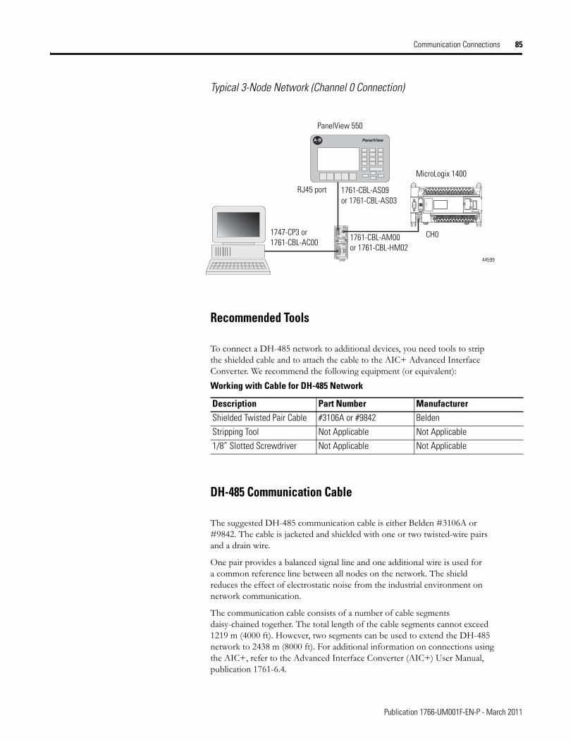
Communication Connections 85
Typical 3-Node Network (Channel 0 Connection)
Recommended Tools
To connect a DH-485 network to additional devices, you need tools to strip the shielded cable and to attach the cable to the AIC+ Advanced Interface Converter. We recommend the following equipment (or equivalent):
DH-485 Communication Cable
The suggested DH-485 communication cable is either Belden #3106A or #9842. The cable is jacketed and shielded with one or two twisted-wire pairs and a drain wire.
One pair provides a balanced signal line and one additional wire is used for a common reference line between all nodes on the network. The shield reduces the effect of electrostatic noise from the industrial environment on network communication.
The communication cable consists of a number of cable segments daisy-chained together. The total length of the cable segments cannot exceed 1219 m (4000 ft). However, two segments can be used to extend the DH-485 network to 2438 m (8000 ft). For additional information on connections using the AIC+, refer to the Advanced Interface Converter (AIC+) User Manual, publication 1761-6.4.
TERM
A
B
COM
SHLD
CHS GND
TX
TX PWR
TX
DC SOURCE CABLE
EXTERNAL
A-B PanelView
PanelView 550
MicroLogix 1400
1761-CBL-AM00or 1761-CBL-HM02
1747-CP3 or 1761-CBL-AC00
RJ45 port 1761-CBL-AS09or 1761-CBL-AS03
CH0
44599
Working with Cable for DH-485 Network
Description Part Number ManufacturerShielded Twisted Pair Cable #3106A or #9842 Belden
Stripping Tool Not Applicable Not Applicable
1/8” Slotted Screwdriver Not Applicable Not Applicable
Publication 1766-UM001F-EN-P - March 2011
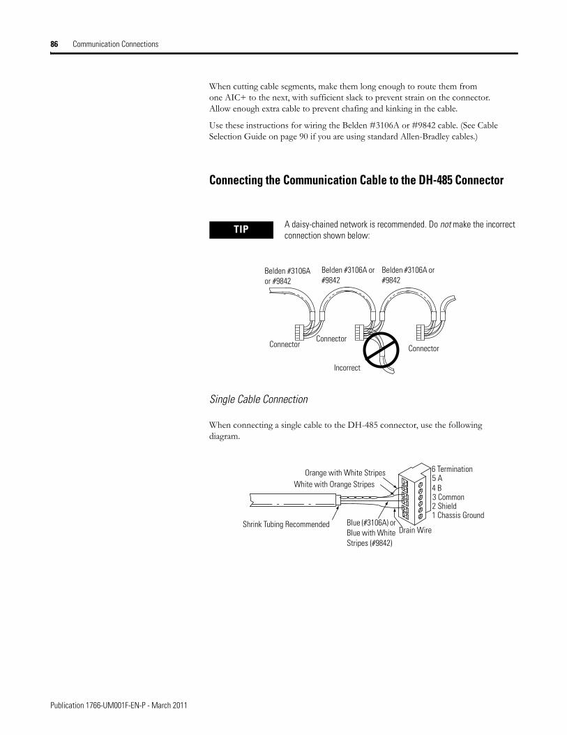
86 Communication Connections
When cutting cable segments, make them long enough to route them from one AIC+ to the next, with sufficient slack to prevent strain on the connector. Allow enough extra cable to prevent chafing and kinking in the cable.
Use these instructions for wiring the Belden #3106A or #9842 cable. (See Cable Selection Guide on page 90 if you are using standard Allen-Bradley cables.)
Connecting the Communication Cable to the DH-485 Connector
Single Cable Connection
When connecting a single cable to the DH-485 connector, use the following diagram.
TIP A daisy-chained network is recommended. Do not make the incorrect connection shown below:
Belden #3106A or #9842
Belden #3106A or #9842
Belden #3106A or #9842
ConnectorConnector
Connector
Incorrect
Orange with White StripesWhite with Orange Stripes
Shrink Tubing Recommended Blue (#3106A) or Blue with White Stripes (#9842)
Drain Wire
6 Termination5 A4 B3 Common2 Shield1 Chassis Ground
Publication 1766-UM001F-EN-P - March 2011
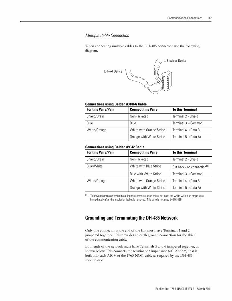
Communication Connections 87
Multiple Cable Connection
When connecting multiple cables to the DH-485 connector, use the following diagram.
Grounding and Terminating the DH-485 Network
Only one connector at the end of the link must have Terminals 1 and 2 jumpered together. This provides an earth ground connection for the shield of the communication cable.
Both ends of the network must have Terminals 5 and 6 jumpered together, as shown below. This connects the termination impedance (of 120 ohm) that is built into each AIC+ or the 1763-NC01 cable as required by the DH-485 specification.
Connections using Belden #3106A CableFor this Wire/Pair Connect this Wire To this Terminal
Shield/Drain Non-jacketed Terminal 2 - Shield
Blue Blue Terminal 3 - (Common)
White/Orange White with Orange Stripe Terminal 4 - (Data B)
Orange with White Stripe Terminal 5 - (Data A)
Connections using Belden #9842 CableFor this Wire/Pair Connect this Wire To this Terminal
Shield/Drain Non-jacketed Terminal 2 - Shield
Blue/White White with Blue Stripe Cut back - no connection(1)
(1) To prevent confusion when installing the communication cable, cut back the white with blue stripe wire immediately after the insulation jacket is removed. This wire is not used by DH-485.
Blue with White Stripe Terminal 3 - (Common)
White/Orange White with Orange Stripe Terminal 4 - (Data B)
Orange with White Stripe Terminal 5 - (Data A)
to Next Device
to Previous Device
Publication 1766-UM001F-EN-P - March 2011
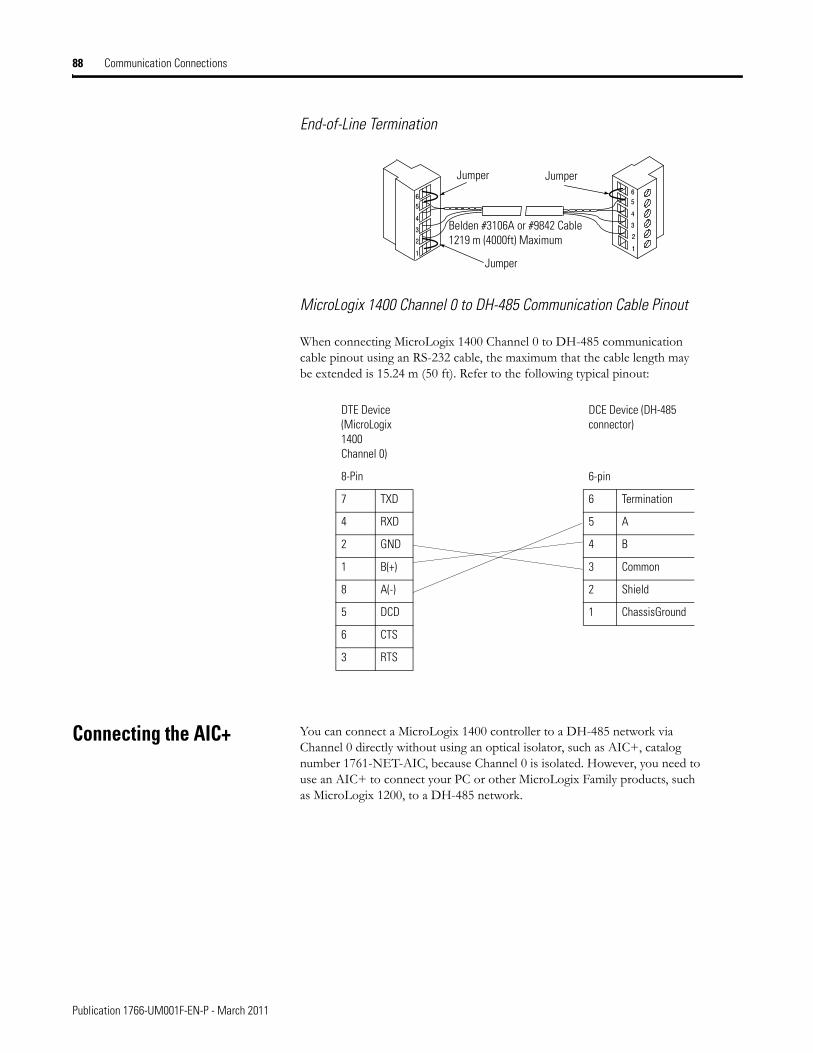
88 Communication Connections
End-of-Line Termination
MicroLogix 1400 Channel 0 to DH-485 Communication Cable Pinout
When connecting MicroLogix 1400 Channel 0 to DH-485 communication cable pinout using an RS-232 cable, the maximum that the cable length may be extended is 15.24 m (50 ft). Refer to the following typical pinout:
Connecting the AIC+ You can connect a MicroLogix 1400 controller to a DH-485 network via Channel 0 directly without using an optical isolator, such as AIC+, catalog number 1761-NET-AIC, because Channel 0 is isolated. However, you need to use an AIC+ to connect your PC or other MicroLogix Family products, such as MicroLogix 1200, to a DH-485 network.
Jumper Jumper
Belden #3106A or #9842 Cable 1219 m (4000ft) Maximum
Jumper
DTE Device(MicroLogix 1400 Channel 0)
DCE Device (DH-485 connector)
8-Pin 6-pin
7 TXD 6 Termination
4 RXD 5 A
2 GND 4 B
1 B(+) 3 Common
8 A(-) 2 Shield
5 DCD 1 ChassisGround
6 CTS
3 RTS
Publication 1766-UM001F-EN-P - March 2011
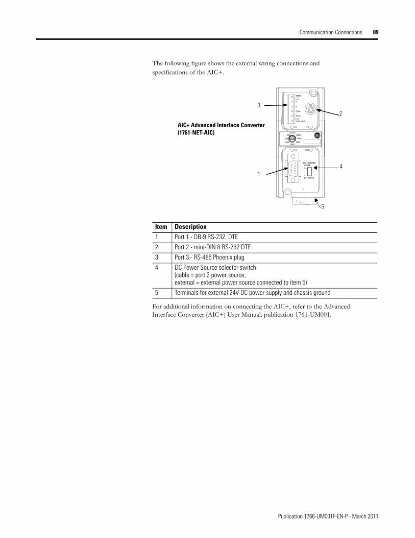
Communication Connections 89
The following figure shows the external wiring connections and specifications of the AIC+.
For additional information on connecting the AIC+, refer to the Advanced Interface Converter (AIC+) User Manual, publication 1761-UM001.
Item Description1 Port 1 - DB-9 RS-232, DTE
2 Port 2 - mini-DIN 8 RS-232 DTE
3 Port 3 - RS-485 Phoenix plug
4 DC Power Source selector switch(cable = port 2 power source, external = external power source connected to item 5)
5 Terminals for external 24V DC power supply and chassis ground
AIC+ Advanced Interface Converter(1761-NET-AIC)
32
4
5
1
Publication 1766-UM001F-EN-P - March 2011
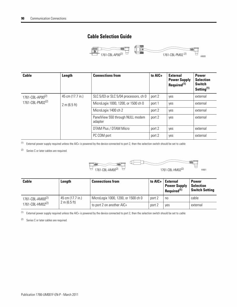
90 Communication Connections
Cable Selection Guide
1761-CBL-PM02 (2)1761-CBL-AP00(2)44600
Cable Length Connections from to AIC+ External Power Supply Required(1)
Power Selection Switch Setting(1)
1761-CBL-AP00(2)
1761-CBL-PM02(2)
45 cm (17.7 in.)
2 m (6.5 ft)
SLC 5/03 or SLC 5/04 processors, ch 0 port 2 yes external
MicroLogix 1000, 1200, or 1500 ch 0 port 1 yes external
MicroLogix 1400 ch 2 port 2 yes external
PanelView 550 through NULL modem adapter
port 2 yes external
DTAM Plus / DTAM Micro port 2 yes external
PC COM port port 2 yes external
(1) External power supply required unless the AIC+ is powered by the device connected to port 2, then the selection switch should be set to cable.
(2) Series C or later cables are required.
1761-CBL-HM02(2)1761-CBL-AM00(2) 44601
Cable Length Connections from to AIC+ External Power Supply Required(1)
Power Selection Switch Setting
1761-CBL-AM00(2)
1761-CBL-HM02(2)
45 cm (17.7 in.)2 m (6.5 ft)
MicroLogix 1000, 1200, or 1500 ch 0 port 2 no cable
to port 2 on another AIC+ port 2 yes external
(1) External power supply required unless the AIC+ is powered by the device connected to port 2, then the selection switch should be set to cable.
(2) Series C or later cables are required.
Publication 1766-UM001F-EN-P - March 2011
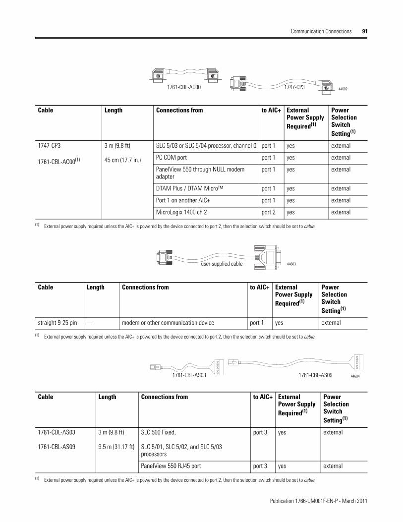
Communication Connections 91
1761-CBL-AC00 1747-CP3 44602
Cable Length Connections from to AIC+ External Power Supply Required(1)
Power Selection Switch Setting(1)
1747-CP3
1761-CBL-AC00(1)
3 m (9.8 ft)
45 cm (17.7 in.)
SLC 5/03 or SLC 5/04 processor, channel 0 port 1 yes external
PC COM port port 1 yes external
PanelView 550 through NULL modem adapter
port 1 yes external
DTAM Plus / DTAM Micro™ port 1 yes external
Port 1 on another AIC+ port 1 yes external
MicroLogix 1400 ch 2 port 2 yes external
(1) External power supply required unless the AIC+ is powered by the device connected to port 2, then the selection switch should be set to cable.
user-supplied cable 44603
Cable Length Connections from to AIC+ External Power Supply Required(1)
Power Selection Switch Setting(1)
straight 9-25 pin — modem or other communication device port 1 yes external
(1) External power supply required unless the AIC+ is powered by the device connected to port 2, then the selection switch should be set to cable.
1761-CBL-AS03 1761-CBL-AS09 44604
Cable Length Connections from to AIC+ External Power Supply Required(1)
Power Selection Switch Setting(1)
1761-CBL-AS03
1761-CBL-AS09
3 m (9.8 ft)
9.5 m (31.17 ft)
SLC 500 Fixed,
SLC 5/01, SLC 5/02, and SLC 5/03 processors
port 3 yes external
PanelView 550 RJ45 port port 3 yes external
(1) External power supply required unless the AIC+ is powered by the device connected to port 2, then the selection switch should be set to cable.
Publication 1766-UM001F-EN-P - March 2011
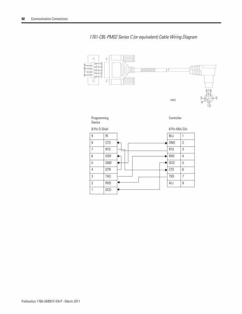
92 Communication Connections
1761-CBL-PM02 Series C (or equivalent) Cable Wiring Diagram
1234
6
5
789
12
3 5
6 87
444605
Programming Device
Controller
9-Pin D-Shell 8-Pin Mini Din
9 RI B(+) 1
8 CTS GND 2
7 RTS RTS 3
6 DSR RXD 4
5 GND DCD 5
4 DTR CTS 6
3 TXD TXD 7
2 RXD A(-) 8
1 DCD
Publication 1766-UM001F-EN-P - March 2011
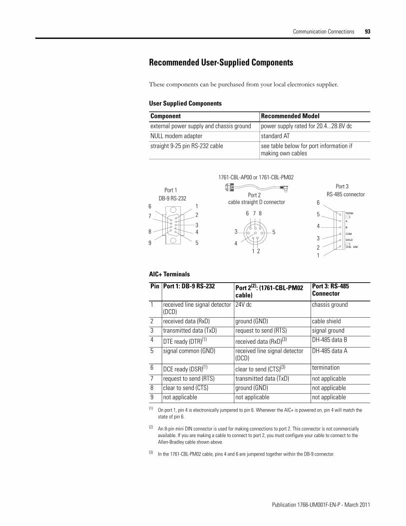
Communication Connections 93
Recommended User-Supplied Components
These components can be purchased from your local electronics supplier.
User Supplied Components
Component Recommended Modelexternal power supply and chassis ground power supply rated for 20.4...28.8V dc
NULL modem adapter standard AT
straight 9-25 pin RS-232 cable see table below for port information if making own cables
1761-CBL-AP00 or 1761-CBL-PM02
DB-9 RS-232RS-485 connector
cable straight D connector
Port 1Port 2
Port 3
6
7
8
9
12
34
5 41 2
5
876
3
6
5
4
3
21
AIC+ Terminals
Pin Port 1: DB-9 RS-232 Port 2(2): (1761-CBL-PM02 cable)
(2) An 8-pin mini DIN connector is used for making connections to port 2. This connector is not commercially available. If you are making a cable to connect to port 2, you must configure your cable to connect to the Allen-Bradley cable shown above.
Port 3: RS-485 Connector
1 received line signal detector (DCD)
24V dc chassis ground
2 received data (RxD) ground (GND) cable shield3 transmitted data (TxD) request to send (RTS) signal ground4 DTE ready (DTR)(1)
(1) On port 1, pin 4 is electronically jumpered to pin 6. Whenever the AIC+ is powered on, pin 4 will match the state of pin 6.
received data (RxD)(3)
(3) In the 1761-CBL-PM02 cable, pins 4 and 6 are jumpered together within the DB-9 connector.
DH-485 data B
5 signal common (GND) received line signal detector (DCD)
DH-485 data A
6 DCE ready (DSR)(1) clear to send (CTS)(3) termination
7 request to send (RTS) transmitted data (TxD) not applicable8 clear to send (CTS) ground (GND) not applicable9 not applicable not applicable not applicable
Publication 1766-UM001F-EN-P - March 2011
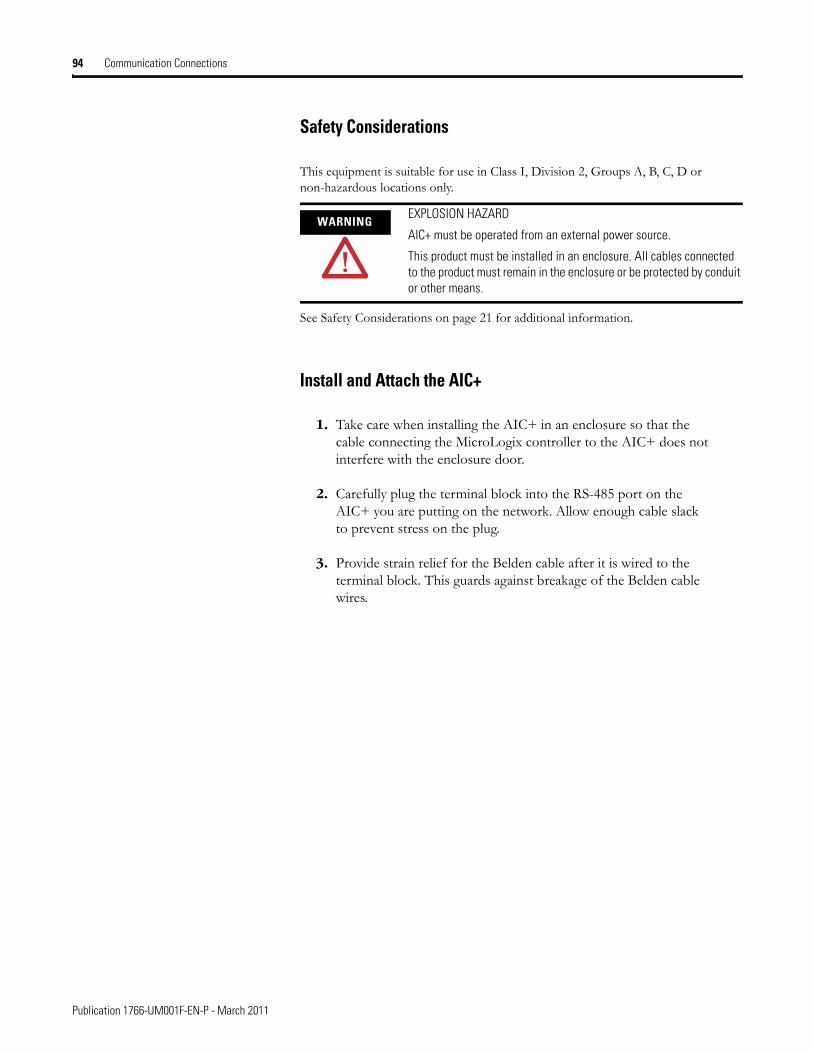
94 Communication Connections
Safety Considerations
This equipment is suitable for use in Class I, Division 2, Groups A, B, C, D or non-hazardous locations only.
See Safety Considerations on page 21 for additional information.
Install and Attach the AIC+
1. Take care when installing the AIC+ in an enclosure so that the cable connecting the MicroLogix controller to the AIC+ does not interfere with the enclosure door.
2. Carefully plug the terminal block into the RS-485 port on the AIC+ you are putting on the network. Allow enough cable slack to prevent stress on the plug.
3. Provide strain relief for the Belden cable after it is wired to the terminal block. This guards against breakage of the Belden cable wires.
WARNINGEXPLOSION HAZARD
AIC+ must be operated from an external power source.
This product must be installed in an enclosure. All cables connected to the product must remain in the enclosure or be protected by conduit or other means.
Publication 1766-UM001F-EN-P - March 2011
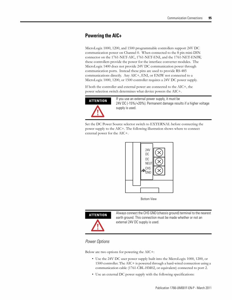
Communication Connections 95
Powering the AIC+
MicroLogix 1000, 1200, and 1500 programmable controllers support 24V DC communication power on Channel 0. When connected to the 8 pin mini-DIN connector on the 1761-NET-AIC, 1761-NET-ENI, and the 1761-NET-ENIW, these controllers provide the power for the interface converter modules. The MicroLogix 1400 does not provide 24V DC communication power through communication ports. Instead these pins are used to provide RS-485 communications directly. Any AIC+, ENI, or ENIW not connected to a MicroLogix 1000, 1200, or 1500 controller requires a 24V DC power supply.
If both the controller and external power are connected to the AIC+, the power selection switch determines what device powers the AIC+.
Set the DC Power Source selector switch to EXTERNAL before connecting the power supply to the AIC+. The following illustration shows where to connect external power for the AIC+.
Power Options
Below are two options for powering the AIC+:
• Use the 24V DC user power supply built into the MicroLogix 1000, 1200, or 1500 controller. The AIC+ is powered through a hard-wired connection using a communication cable (1761-CBL-HM02, or equivalent) connected to port 2.
• Use an external DC power supply with the following specifications:
ATTENTION If you use an external power supply, it must be 24V DC (-15%/+20%). Permanent damage results if a higher voltage supply is used.
ATTENTION Always connect the CHS GND (chassis ground) terminal to the nearest earth ground. This connection must be made whether or not an external 24V DC supply is used.
24V DCDCNEUTCHSGND
Bottom View
Publication 1766-UM001F-EN-P - March 2011
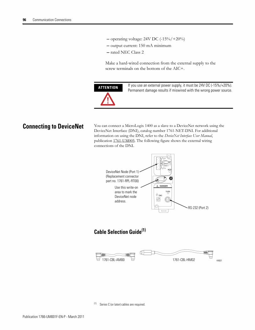
96 Communication Connections
– operating voltage: 24V DC (-15%/+20%)
– output current: 150 mA minimum
– rated NEC Class 2
Make a hard-wired connection from the external supply to the screw terminals on the bottom of the AIC+.
Connecting to DeviceNet You can connect a MicroLogix 1400 as a slave to a DeviceNet network using the DeviceNet Interface (DNI), catalog number 1761-NET-DNI. For additional information on using the DNI, refer to the DeviceNet Interface User Manual, publication 1761-UM005. The following figure shows the external wiring connections of the DNI.
Cable Selection Guide(1)
ATTENTION If you use an external power supply, it must be 24V DC (-15%/+20%). Permanent damage results if miswired with the wrong power source.
(1) Series C (or later) cables are required.
V–
CAN_L
SHIELD
CAN_H
V+
NET
MOD
NODE
DANGER
GND
TX/RX
DeviceNet Node (Port 1)(Replacement connector part no. 1761-RPL-RT00)
Use this write-on area to mark the DeviceNet node address.
RS-232 (Port 2)
1761-CBL-HM021761-CBL-AM00 44601
Publication 1766-UM001F-EN-P - March 2011
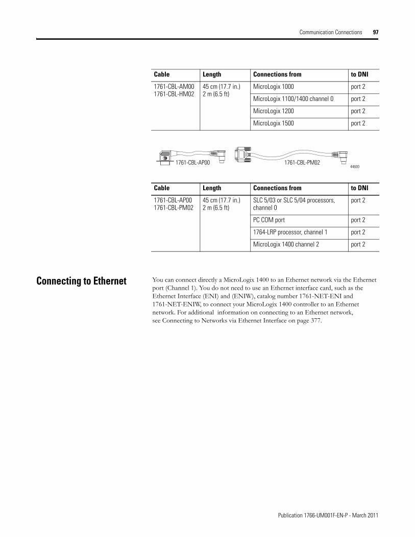
Communication Connections 97
Connecting to Ethernet You can connect directly a MicroLogix 1400 to an Ethernet network via the Ethernet port (Channel 1). You do not need to use an Ethernet interface card, such as the Ethernet Interface (ENI) and (ENIW), catalog number 1761-NET-ENI and 1761-NET-ENIW, to connect your MicroLogix 1400 controller to an Ethernet network. For additional information on connecting to an Ethernet network, see Connecting to Networks via Ethernet Interface on page 377.
Cable Length Connections from to DNI
1761-CBL-AM001761-CBL-HM02
45 cm (17.7 in.)2 m (6.5 ft)
MicroLogix 1000 port 2
MicroLogix 1100/1400 channel 0 port 2
MicroLogix 1200 port 2
MicroLogix 1500 port 2
1761-CBL-PM02 1761-CBL-AP0044600
Cable Length Connections from to DNI
1761-CBL-AP001761-CBL-PM02
45 cm (17.7 in.)2 m (6.5 ft)
SLC 5/03 or SLC 5/04 processors, channel 0
port 2
PC COM port port 2
1764-LRP processor, channel 1 port 2
MicroLogix 1400 channel 2 port 2
Publication 1766-UM001F-EN-P - March 2011
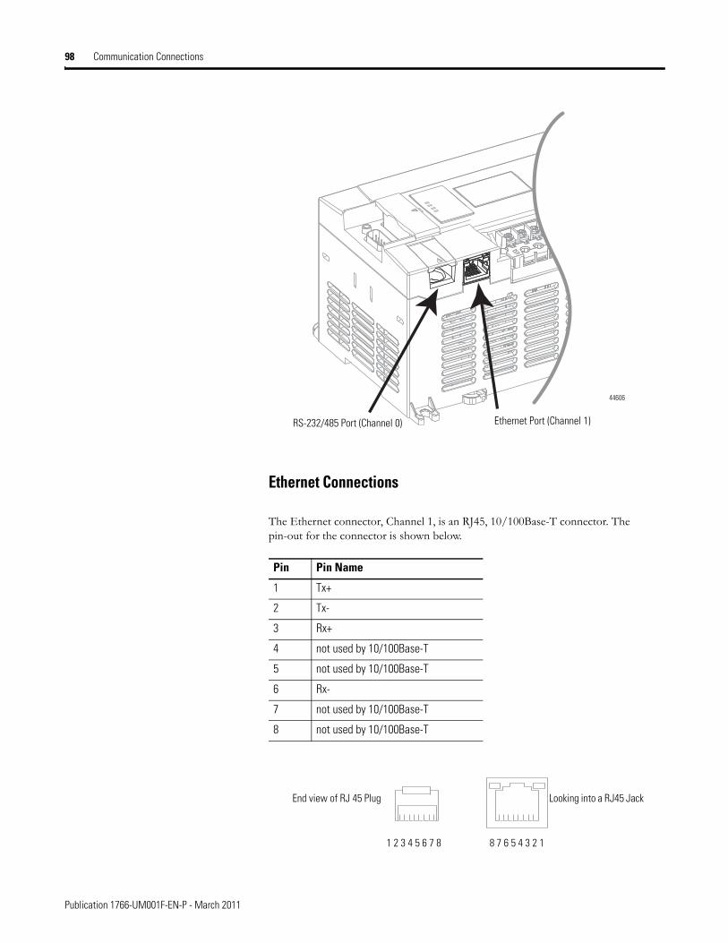
98 Communication Connections
Ethernet Connections
The Ethernet connector, Channel 1, is an RJ45, 10/100Base-T connector. The pin-out for the connector is shown below.
Pin Pin Name
1 Tx+
2 Tx-
3 Rx+
4 not used by 10/100Base-T
5 not used by 10/100Base-T
6 Rx-
7 not used by 10/100Base-T
8 not used by 10/100Base-T
RS-232/485 Port (Channel 0) Ethernet Port (Channel 1)
44606
8 7 6 5 4 3 2 11 2 3 4 5 6 7 8
End view of RJ 45 Plug Looking into a RJ45 Jack
Publication 1766-UM001F-EN-P - March 2011

Communication Connections 99
When to use straight-through and cross-over cable:
• MicroLogix 1400 Ethernet port to 10/100Base-T Ethernet switch cables utilize a straight-through pin-out (1-1, 2-2, 3-3, 6-6).
• Direct point-to-point 10/100 Base-T cables connecting the MicroLogix 1400 Ethernet port directly to another Ethernet port (or a computer 10/100Base-T port) require a cross-over pin-out (1-3, 2-6, 3-1, 6-2).
TIP For more information on using ethernet cables with MicroLogix 1400, see MicroLogix 1400 and PC Connections to the Ethernet Network on page 379.
Publication 1766-UM001F-EN-P - March 2011

100 Communication Connections
Notes:
Publication 1766-UM001F-EN-P - March 2011
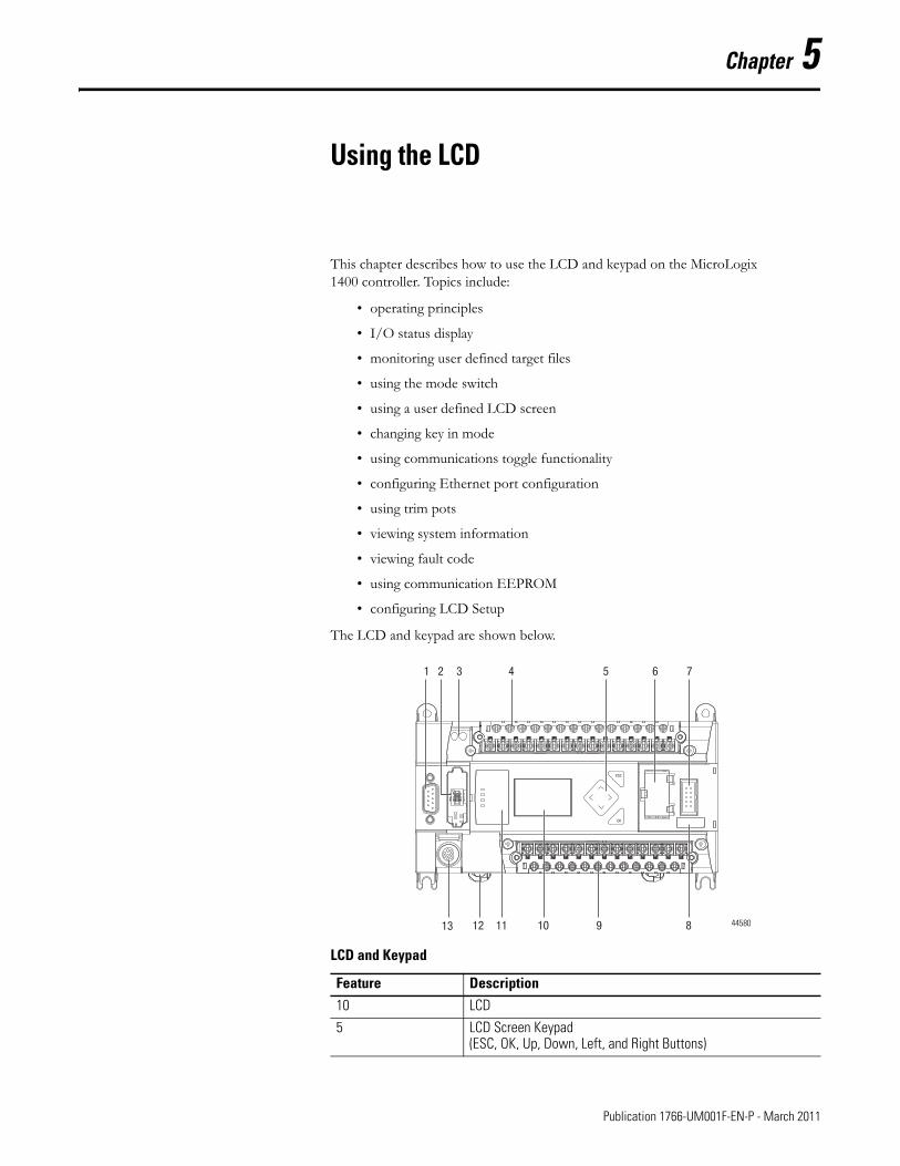
Chapter 5
Using the LCD
This chapter describes how to use the LCD and keypad on the MicroLogix 1400 controller. Topics include:
• operating principles
• I/O status display
• monitoring user defined target files
• using the mode switch
• using a user defined LCD screen
• changing key in mode
• using communications toggle functionality
• configuring Ethernet port configuration
• using trim pots
• viewing system information
• viewing fault code
• using communication EEPROM
• configuring LCD Setup
The LCD and keypad are shown below.
LCD and Keypad
Feature Description10 LCD
5 LCD Screen Keypad(ESC, OK, Up, Down, Left, and Right Buttons)
Top View1 2 5 6 7
89101113 12
43
ESC
OK
44580
101 Publication 1766-UM001F-EN-P - March 2011
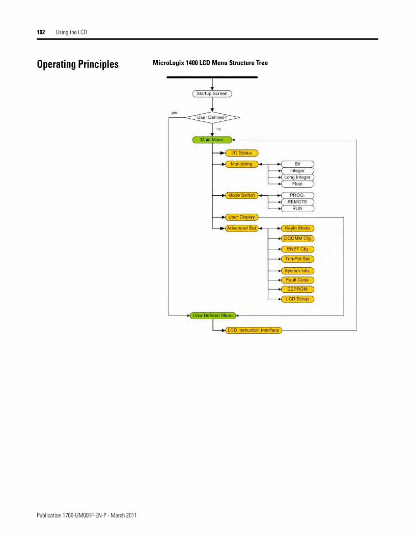
102 Using the LCD
Operating Principles MicroLogix 1400 LCD Menu Structure Tree
Publication 1766-UM001F-EN-P - March 2011
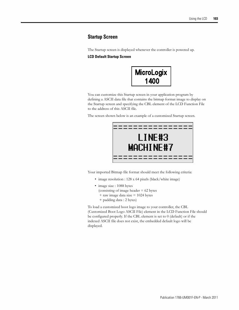
Using the LCD 103
Startup Screen
The Startup screen is displayed whenever the controller is powered up.
LCD Default Startup Screen
You can customize this Startup screen in your application program by defining a ASCII data file that contains the bitmap format image to display on the Startup screen and specifying the CBL element of the LCD Function File to the address of this ASCII file.
The screen shown below is an example of a customized Startup screen.
Your imported Bitmap file format should meet the following criteria:
• image resolution : 128 x 64 pixels (black/white image)
• image size : 1088 bytes(consisting of image header = 62 bytes + raw image data size = 1024 bytes + padding data : 2 bytes)
To load a customized boot logo image to your controller, the CBL (Customized Boot Logo ASCII File) element in the LCD Function File should be configured properly. If the CBL element is set to 0 (default) or if the indexed ASCII file does not exist, the embedded default logo will be displayed.
Publication 1766-UM001F-EN-P - March 2011
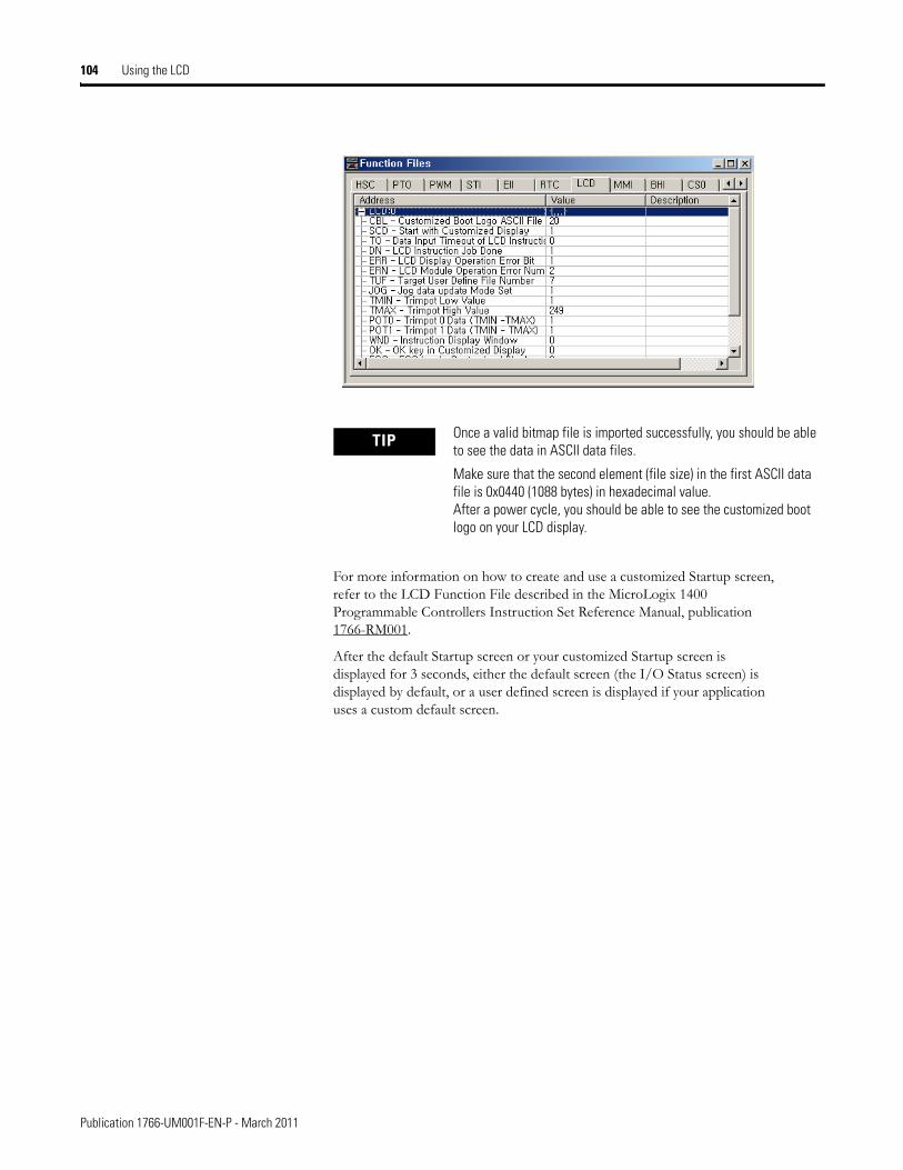
104 Using the LCD
For more information on how to create and use a customized Startup screen, refer to the LCD Function File described in the MicroLogix 1400 Programmable Controllers Instruction Set Reference Manual, publication 1766-RM001.
After the default Startup screen or your customized Startup screen is displayed for 3 seconds, either the default screen (the I/O Status screen) is displayed by default, or a user defined screen is displayed if your application uses a custom default screen.
TIP Once a valid bitmap file is imported successfully, you should be able to see the data in ASCII data files.
Make sure that the second element (file size) in the first ASCII data file is 0x0440 (1088 bytes) in hexadecimal value. After a power cycle, you should be able to see the customized boot logo on your LCD display.
Publication 1766-UM001F-EN-P - March 2011
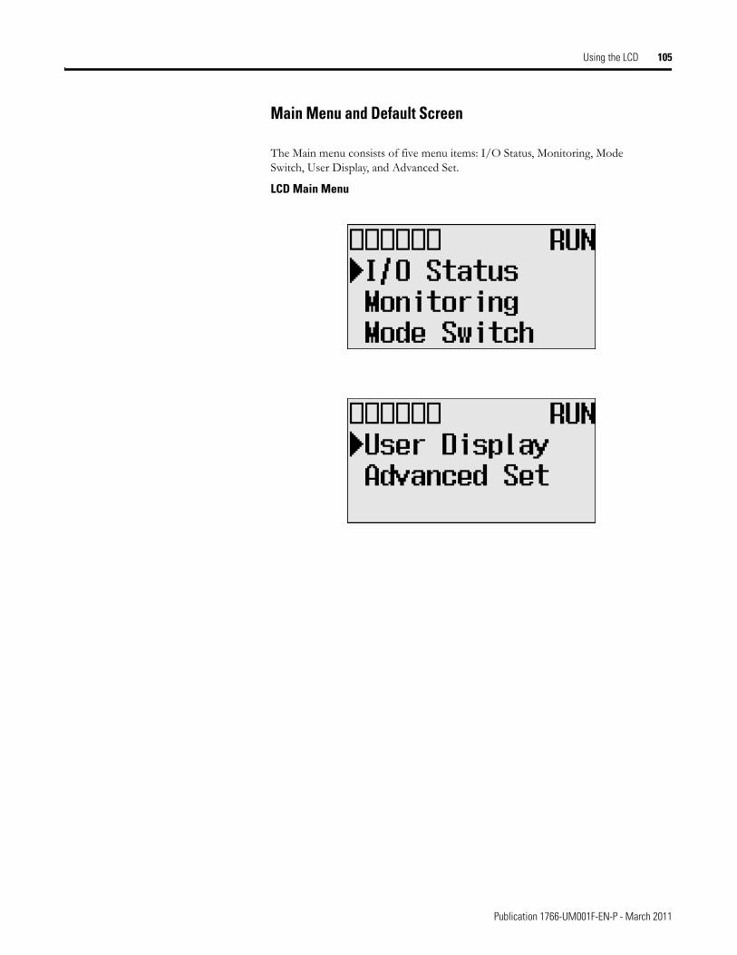
Using the LCD 105
Main Menu and Default Screen
The Main menu consists of five menu items: I/O Status, Monitoring, Mode Switch, User Display, and Advanced Set.
LCD Main Menu
Publication 1766-UM001F-EN-P - March 2011
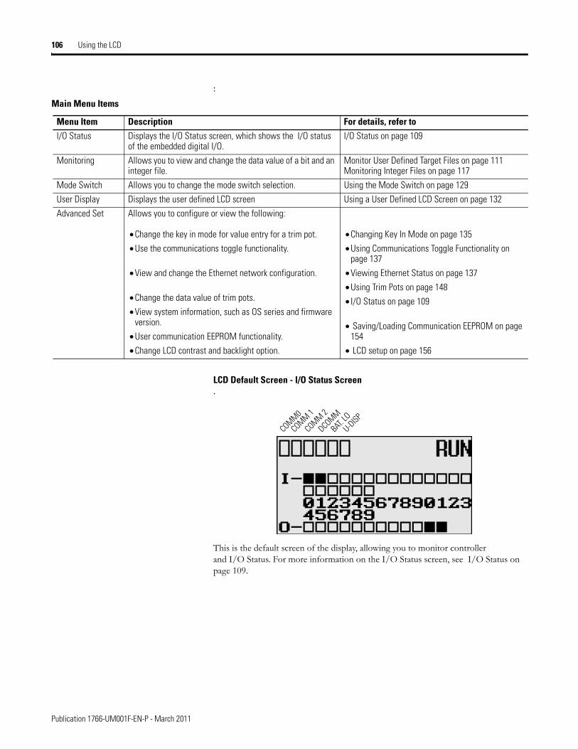
106 Using the LCD
:
LCD Default Screen - I/O Status Screen.
This is the default screen of the display, allowing you to monitor controller and I/O Status. For more information on the I/O Status screen, see I/O Status on page 109.
Main Menu Items
Menu Item Description For details, refer toI/O Status Displays the I/O Status screen, which shows the I/O status
of the embedded digital I/O.I/O Status on page 109
Monitoring Allows you to view and change the data value of a bit and an integer file.
Monitor User Defined Target Files on page 111Monitoring Integer Files on page 117
Mode Switch Allows you to change the mode switch selection. Using the Mode Switch on page 129
User Display Displays the user defined LCD screen Using a User Defined LCD Screen on page 132
Advanced Set Allows you to configure or view the following:
• Change the key in mode for value entry for a trim pot.
• Use the communications toggle functionality.
• View and change the Ethernet network configuration.
• Change the data value of trim pots.
• View system information, such as OS series and firmware version.
• User communication EEPROM functionality.
• Change LCD contrast and backlight option.
• Changing Key In Mode on page 135
• Using Communications Toggle Functionality on page 137
• Viewing Ethernet Status on page 137
• Using Trim Pots on page 148
• I/O Status on page 109
• Saving/Loading Communication EEPROM on page 154
• LCD setup on page 156
COMM0
COMM 1
DCOMM
BAT. LO
U-DISPCOMM 2
Publication 1766-UM001F-EN-P - March 2011
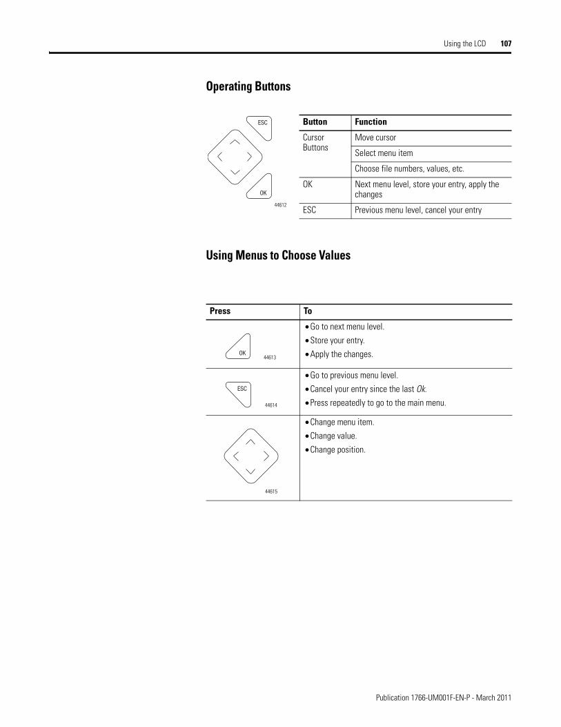
Using the LCD 107
Operating Buttons
Using Menus to Choose Values
Button Function
Cursor Buttons
Move cursor
Select menu item
Choose file numbers, values, etc.
OK Next menu level, store your entry, apply the changes
ESC Previous menu level, cancel your entry
Press To
• Go to next menu level.
• Store your entry.
• Apply the changes.
• Go to previous menu level.
• Cancel your entry since the last Ok.
• Press repeatedly to go to the main menu.
• Change menu item.
• Change value.
• Change position.
ESC
OK
44612
OK44613
ESC
44614
44615
Publication 1766-UM001F-EN-P - March 2011
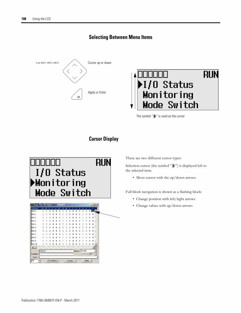
108 Using the LCD
Selecting Between Menu Items
Cursor Display
Cursor up or down
Apply or Enter
The symbol " " is used as the cursor.
to be 44612, 44613, 44614
OK
There are two different cursor types:
Selection cursor (the symbol “ ”) is displayed left to the selected item.
• Move cursor with the up/down arrows
Full block navigation is shown as a flashing block:
• Change position with left/right arrows
• Change values with up/down arrows
Publication 1766-UM001F-EN-P - March 2011
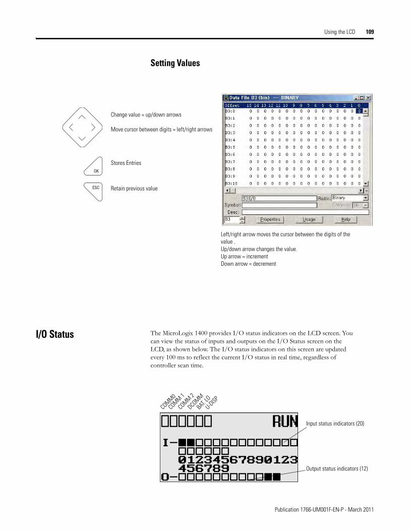
Using the LCD 109
Setting Values
I/O Status The MicroLogix 1400 provides I/O status indicators on the LCD screen. You can view the status of inputs and outputs on the I/O Status screen on the LCD, as shown below. The I/O status indicators on this screen are updated every 100 ms to reflect the current I/O status in real time, regardless of controller scan time.
Change value = up/down arrows
Move cursor between digits = left/right arrows
Stores Entries
Retain previous value
Left/right arrow moves the cursor between the digits of the value .Up/down arrow changes the value.Up arrow = incrementDown arrow = decrement
ESC
OK
Output status indicators (12)
Input status indicators (20)
COMM0
COMM 1
DCOMM
BAT. LO
U-DISPCOMM 2
Publication 1766-UM001F-EN-P - March 2011
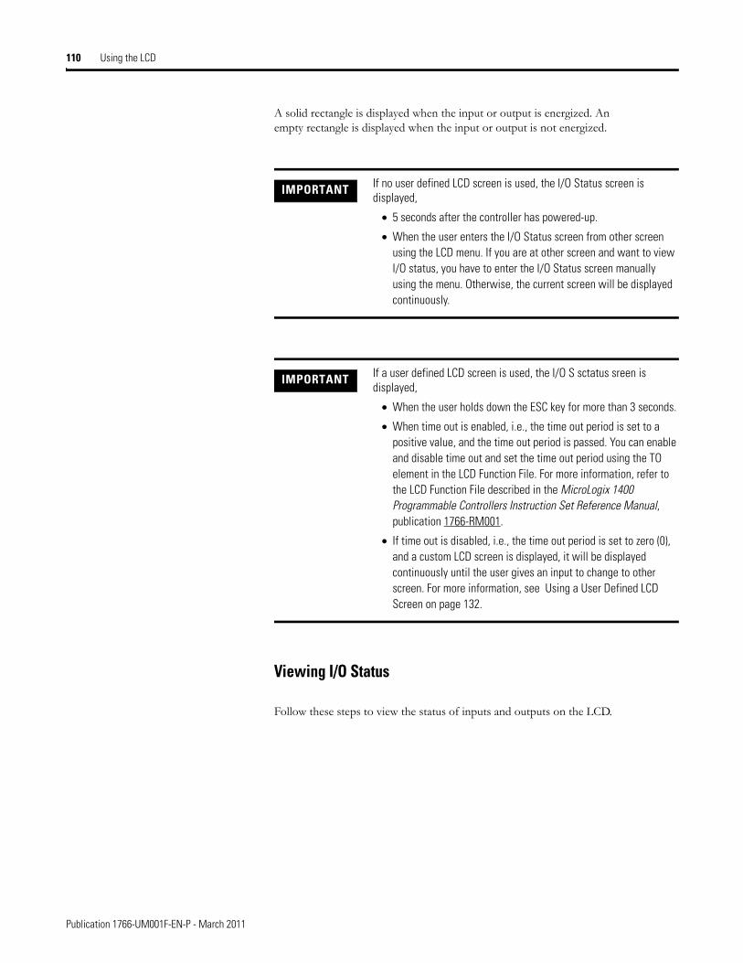
110 Using the LCD
A solid rectangle is displayed when the input or output is energized. An empty rectangle is displayed when the input or output is not energized.
Viewing I/O Status
Follow these steps to view the status of inputs and outputs on the LCD.
IMPORTANT If no user defined LCD screen is used, the I/O Status screen is displayed,
• 5 seconds after the controller has powered-up.
• When the user enters the I/O Status screen from other screen using the LCD menu. If you are at other screen and want to view I/O status, you have to enter the I/O Status screen manually using the menu. Otherwise, the current screen will be displayed continuously.
IMPORTANT If a user defined LCD screen is used, the I/O S sctatus sreen is displayed,
• When the user holds down the ESC key for more than 3 seconds.
• When time out is enabled, i.e., the time out period is set to a positive value, and the time out period is passed. You can enable and disable time out and set the time out period using the TO element in the LCD Function File. For more information, refer to the LCD Function File described in the MicroLogix 1400 Programmable Controllers Instruction Set Reference Manual, publication 1766-RM001.
• If time out is disabled, i.e., the time out period is set to zero (0), and a custom LCD screen is displayed, it will be displayed continuously until the user gives an input to change to other screen. For more information, see Using a User Defined LCD Screen on page 132.
Publication 1766-UM001F-EN-P - March 2011
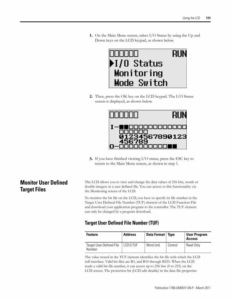
Using the LCD 111
1. On the Main Menu screen, select I/O Status by using the Up and Down keys on the LCD keypad, as shown below.
2. Then, press the OK key on the LCD keypad. The I/O Status screen is displayed, as shown below.
3. If you have finished viewing I/O status, press the ESC key to return to the Main Menu screen, as shown in step 1.
Monitor User Defined Target Files
The LCD allows you to view and change the data values of 256 bits, words or double integers in a user defined file. You can access to this functionality via the Monitoring screen of the LCD.
To monitor the bit file on the LCD, you have to specify its file number in the Target User Defined File Number (TUF) element of the LCD Function File and download your application program to the controller. The TUF element can only be changed by a program download.
Target User Defined File Number (TUF)
The value stored in the TUF element identifies the bit file with which the LCD will interface. Valid bit files are B3, and B10 through B255. When the LCD reads a valid bit file number, it can access up to 256 bits (0 to 255) on the LCD screen. The protection bit (LCD edit disable) in the data file properties
Feature Address Data Format Type User Program Access
Target User Defined File Number
LCD:0.TUF Word (int) Control Read Only
Publication 1766-UM001F-EN-P - March 2011
112 Using the LCD
of target bit file are used to define the read-only or read/write privileges for its file.
The file type that the LCD interfaces with is bit, integer, double integer or float file specified in the TUF element.
The data protection for a file depends on the LCD edit disable setting. When LCD Edit Disable is set (1: Checked) in file properties, the corresponding data file is considered read-only by and the “Protected!” message is displayed. When LCD Edit Disable is clear (0: Unchecked), the “UnProtected!” message is displayed and the corresponding data file is editable from the LCD keypad.
Monitoring a Bit File
For explanations in this section, we assume the following in the application program:
IMPORTANT Use your programming software to ensure that the bit file you specify in the TUF element, as well as the appropriate number of elements, exist in the MicroLogix 1400 user program.
IMPORTANT Although you cannot change protected data from the LCD keypad, the control program or other communication devices do have access to this data. The Protection bit (LCD Edit Disable) only provides write protection from the LCD keypad. This does not provide any overwrite protection from ladder logic, HMI, or programming software. It is the user’s responsibility to ensure that data is not inadvertently overwritten.
TIP The LCD always starts at bit 0 of a data file. It cannot start at any other address within the file.
Publication 1766-UM001F-EN-P - March 2011
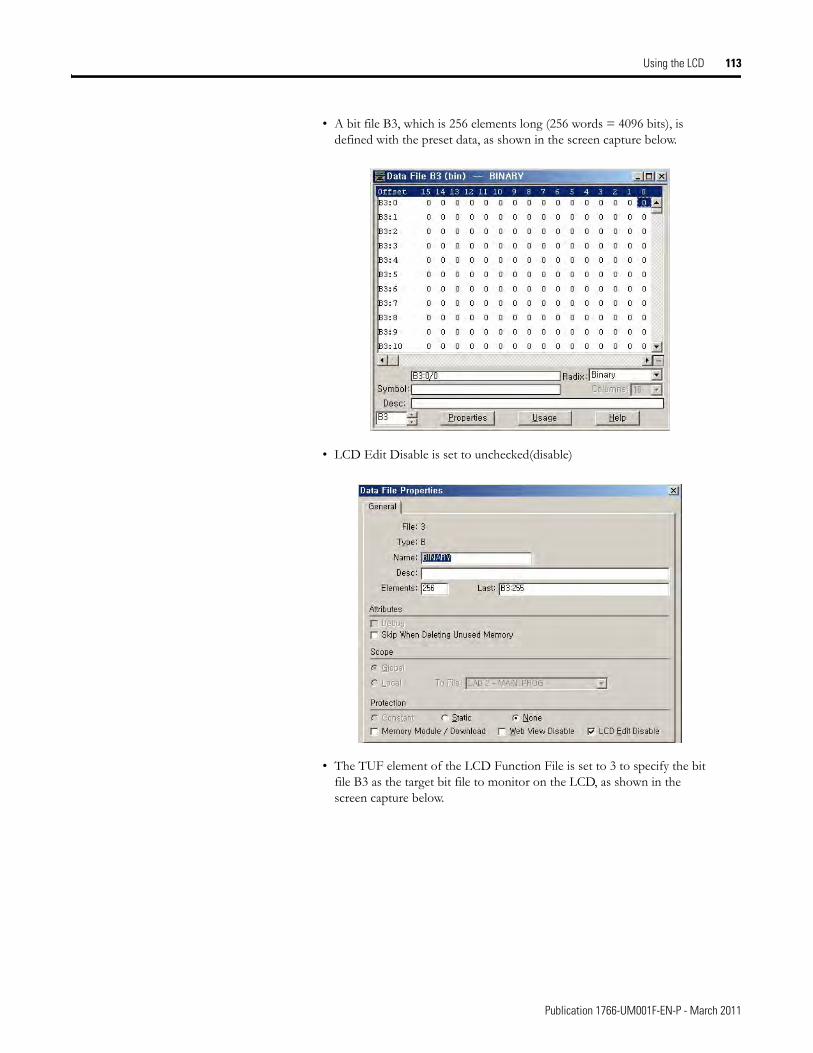
Using the LCD 113
• A bit file B3, which is 256 elements long (256 words = 4096 bits), is defined with the preset data, as shown in the screen capture below.
• LCD Edit Disable is set to unchecked(disable)
• The TUF element of the LCD Function File is set to 3 to specify the bit file B3 as the target bit file to monitor on the LCD, as shown in the screen capture below.
Publication 1766-UM001F-EN-P - March 2011
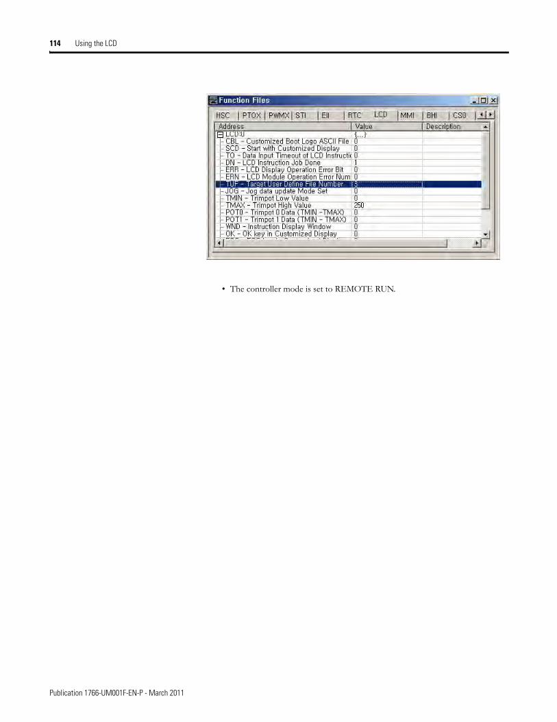
114 Using the LCD
• The controller mode is set to REMOTE RUN.
Publication 1766-UM001F-EN-P - March 2011
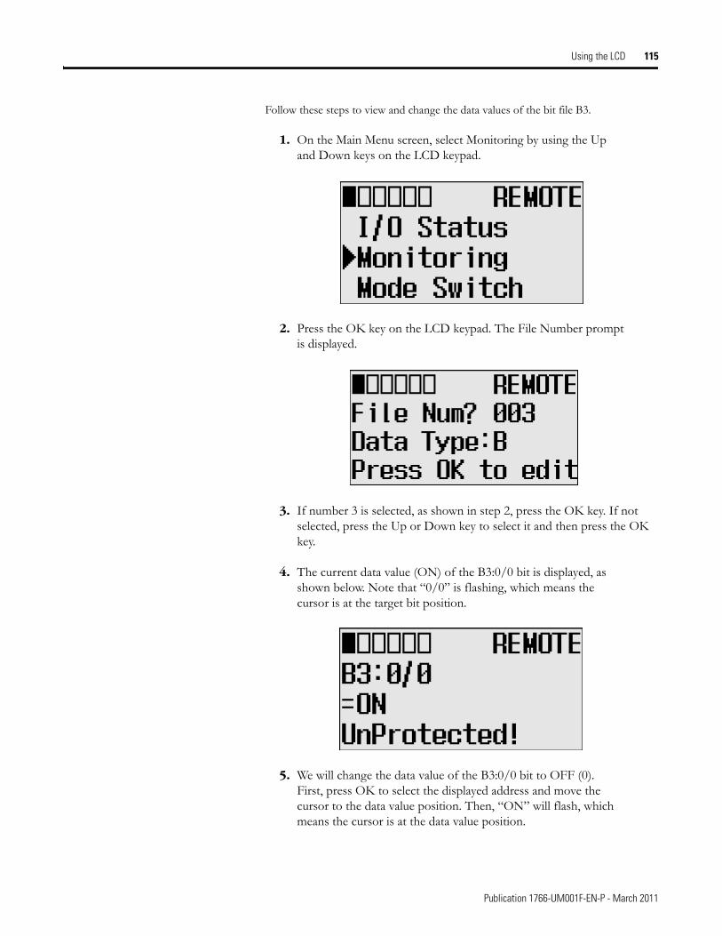
Using the LCD 115
Follow these steps to view and change the data values of the bit file B3.
1. On the Main Menu screen, select Monitoring by using the Up and Down keys on the LCD keypad.
2. Press the OK key on the LCD keypad. The File Number prompt is displayed.
3. If number 3 is selected, as shown in step 2, press the OK key. If not selected, press the Up or Down key to select it and then press the OK key.
4. The current data value (ON) of the B3:0/0 bit is displayed, as shown below. Note that “0/0” is flashing, which means the cursor is at the target bit position.
5. We will change the data value of the B3:0/0 bit to OFF (0). First, press OK to select the displayed address and move the cursor to the data value position. Then, “ON” will flash, which means the cursor is at the data value position.
Publication 1766-UM001F-EN-P - March 2011
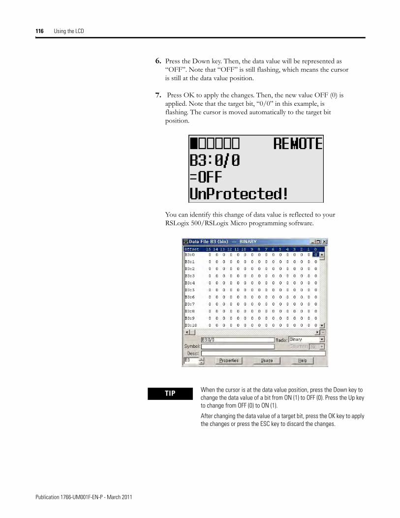
116 Using the LCD
6. Press the Down key. Then, the data value will be represented as “OFF”. Note that “OFF” is still flashing, which means the cursor is still at the data value position.
7. Press OK to apply the changes. Then, the new value OFF (0) is applied. Note that the target bit, “0/0” in this example, is flashing. The cursor is moved automatically to the target bit position.
You can identify this change of data value is reflected to your RSLogix 500/RSLogix Micro programming software.
TIP When the cursor is at the data value position, press the Down key to change the data value of a bit from ON (1) to OFF (0). Press the Up key to change from OFF (0) to ON (1).
After changing the data value of a target bit, press the OK key to apply the changes or press the ESC key to discard the changes.
Publication 1766-UM001F-EN-P - March 2011
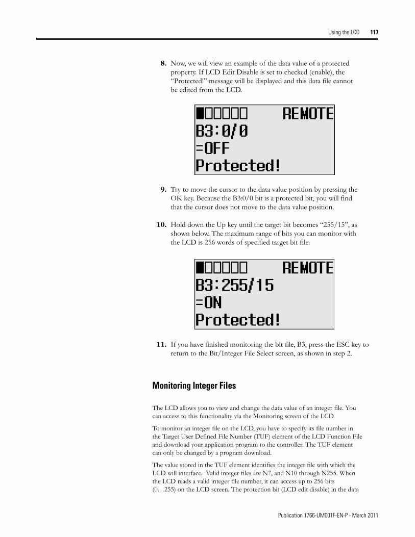
Using the LCD 117
8. Now, we will view an example of the data value of a protected property. If LCD Edit Disable is set to checked (enable), the “Protected!” message will be displayed and this data file cannot be edited from the LCD.
9. Try to move the cursor to the data value position by pressing the OK key. Because the B3:0/0 bit is a protected bit, you will find that the cursor does not move to the data value position.
10. Hold down the Up key until the target bit becomes “255/15”, as shown below. The maximum range of bits you can monitor with the LCD is 256 words of specified target bit file.
11. If you have finished monitoring the bit file, B3, press the ESC key to return to the Bit/Integer File Select screen, as shown in step 2.
Monitoring Integer Files
The LCD allows you to view and change the data value of an integer file. You can access to this functionality via the Monitoring screen of the LCD.
To monitor an integer file on the LCD, you have to specify its file number in the Target User Defined File Number (TUF) element of the LCD Function File and download your application program to the controller. The TUF element can only be changed by a program download.
The value stored in the TUF element identifies the integer file with which the LCD will interface. Valid integer files are N7, and N10 through N255. When the LCD reads a valid integer file number, it can access up to 256 bits (0…255) on the LCD screen. The protection bit (LCD edit disable) in the data
Publication 1766-UM001F-EN-P - March 2011
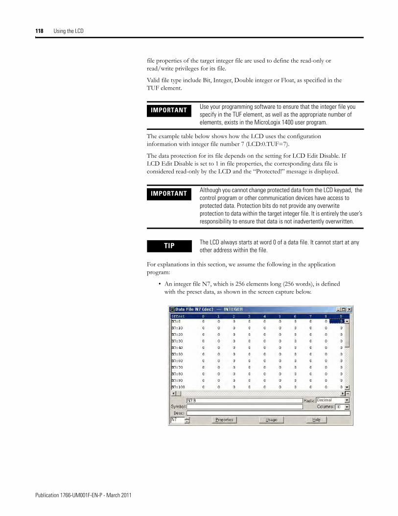
118 Using the LCD
file properties of the target integer file are used to define the read-only or read/write privileges for its file.
Valid file type include Bit, Integer, Double integer or Float, as specified in the TUF element.
The example table below shows how the LCD uses the configuration information with integer file number 7 (LCD:0.TUF=7).
The data protection for its file depends on the setting for LCD Edit Disable. If LCD Edit Disable is set to 1 in file properties, the corresponding data file is considered read-only by the LCD and the “Protected!” message is displayed.
For explanations in this section, we assume the following in the application program:
• An integer file N7, which is 256 elements long (256 words), is defined with the preset data, as shown in the screen capture below.
IMPORTANT Use your programming software to ensure that the integer file you specify in the TUF element, as well as the appropriate number of elements, exists in the MicroLogix 1400 user program.
IMPORTANT Although you cannot change protected data from the LCD keypad, the control program or other communication devices have access to protected data. Protection bits do not provide any overwrite protection to data within the target integer file. It is entirely the user’s responsibility to ensure that data is not inadvertently overwritten.
TIP The LCD always starts at word 0 of a data file. It cannot start at any other address within the file.
Publication 1766-UM001F-EN-P - March 2011
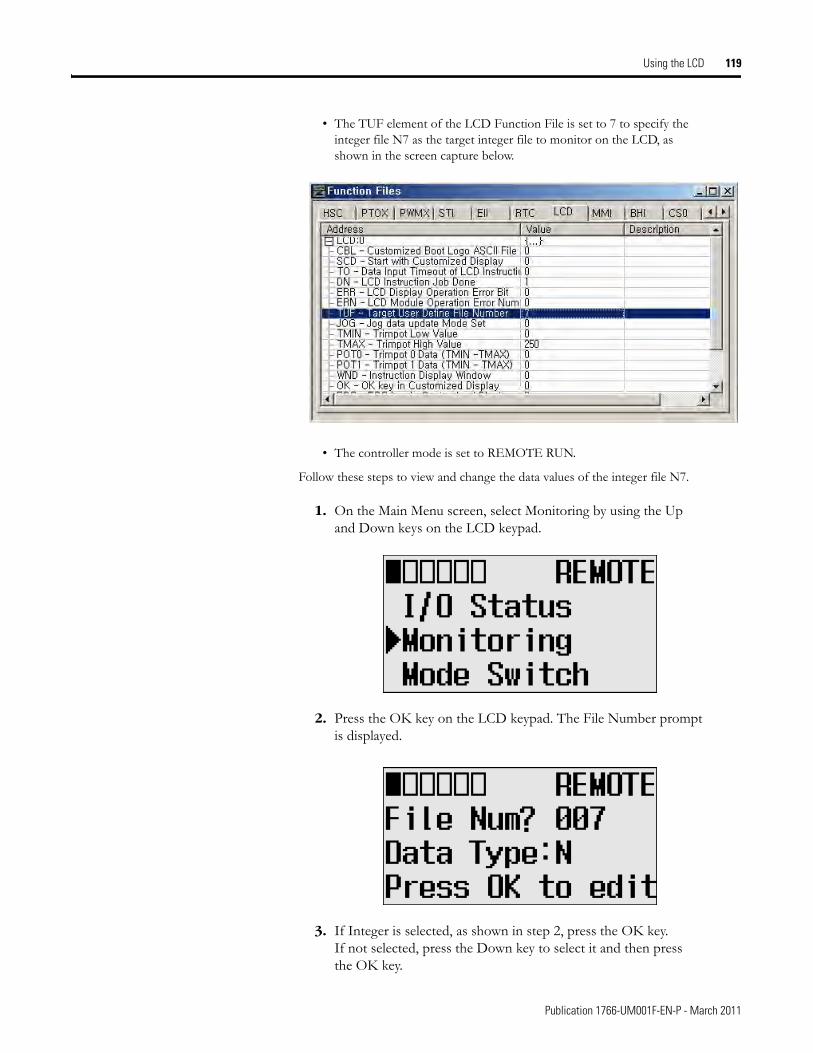
Using the LCD 119
• The TUF element of the LCD Function File is set to 7 to specify the integer file N7 as the target integer file to monitor on the LCD, as shown in the screen capture below.
• The controller mode is set to REMOTE RUN.
Follow these steps to view and change the data values of the integer file N7.
1. On the Main Menu screen, select Monitoring by using the Up and Down keys on the LCD keypad.
2. Press the OK key on the LCD keypad. The File Number prompt is displayed.
3. If Integer is selected, as shown in step 2, press the OK key.If not selected, press the Down key to select it and then press the OK key.
Publication 1766-UM001F-EN-P - March 2011
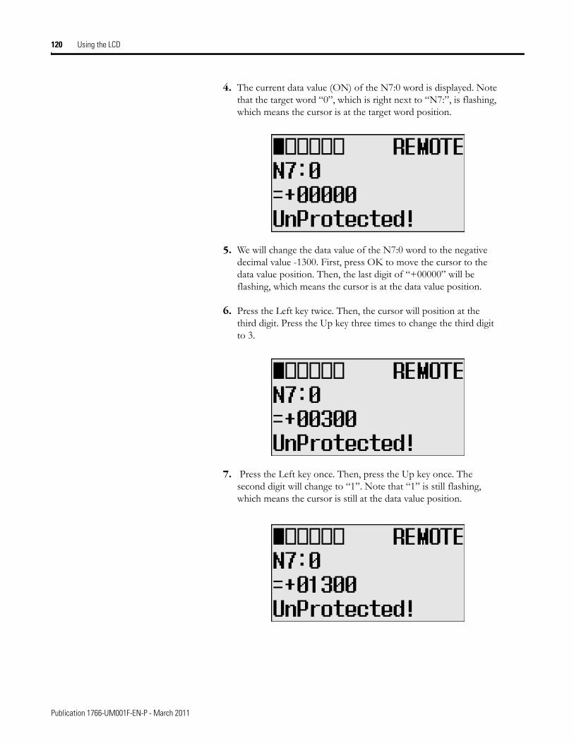
120 Using the LCD
4. The current data value (ON) of the N7:0 word is displayed. Note that the target word “0”, which is right next to “N7:”, is flashing, which means the cursor is at the target word position.
5. We will change the data value of the N7:0 word to the negative decimal value -1300. First, press OK to move the cursor to the data value position. Then, the last digit of “+00000” will be flashing, which means the cursor is at the data value position.
6. Press the Left key twice. Then, the cursor will position at the third digit. Press the Up key three times to change the third digit to 3.
7. Press the Left key once. Then, press the Up key once. The second digit will change to “1”. Note that “1” is still flashing, which means the cursor is still at the data value position.
Publication 1766-UM001F-EN-P - March 2011
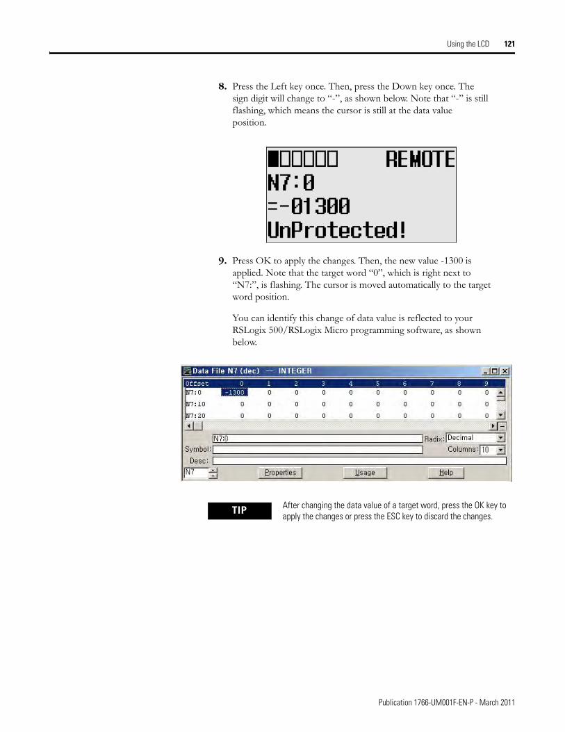
Using the LCD 121
8. Press the Left key once. Then, press the Down key once. The sign digit will change to “-”, as shown below. Note that “-” is still flashing, which means the cursor is still at the data value position.
9. Press OK to apply the changes. Then, the new value -1300 is applied. Note that the target word “0”, which is right next to “N7:”, is flashing. The cursor is moved automatically to the target word position.
You can identify this change of data value is reflected to your RSLogix 500/RSLogix Micro programming software, as shown below.
TIP After changing the data value of a target word, press the OK key to apply the changes or press the ESC key to discard the changes.
Publication 1766-UM001F-EN-P - March 2011
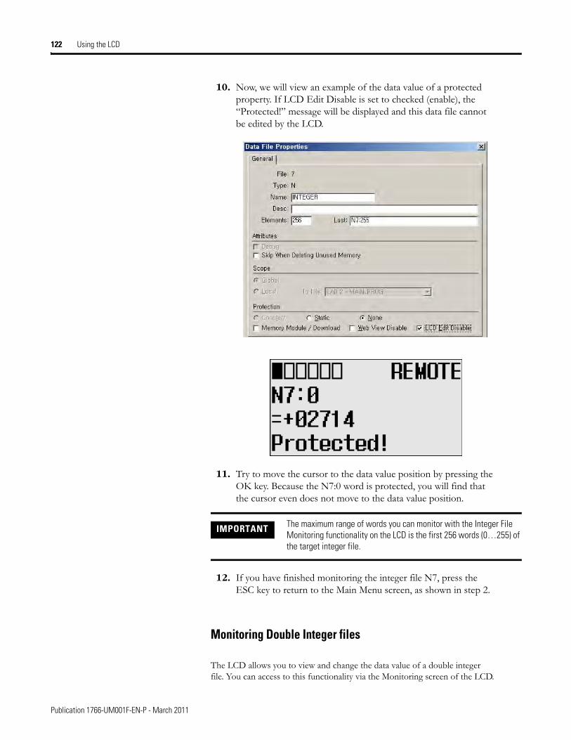
122 Using the LCD
10. Now, we will view an example of the data value of a protected property. If LCD Edit Disable is set to checked (enable), the “Protected!” message will be displayed and this data file cannot be edited by the LCD.
11. Try to move the cursor to the data value position by pressing the OK key. Because the N7:0 word is protected, you will find that the cursor even does not move to the data value position.
12. If you have finished monitoring the integer file N7, press the ESC key to return to the Main Menu screen, as shown in step 2.
Monitoring Double Integer files
The LCD allows you to view and change the data value of a double integer file. You can access to this functionality via the Monitoring screen of the LCD.
IMPORTANT The maximum range of words you can monitor with the Integer File Monitoring functionality on the LCD is the first 256 words (0…255) of the target integer file.
Publication 1766-UM001F-EN-P - March 2011
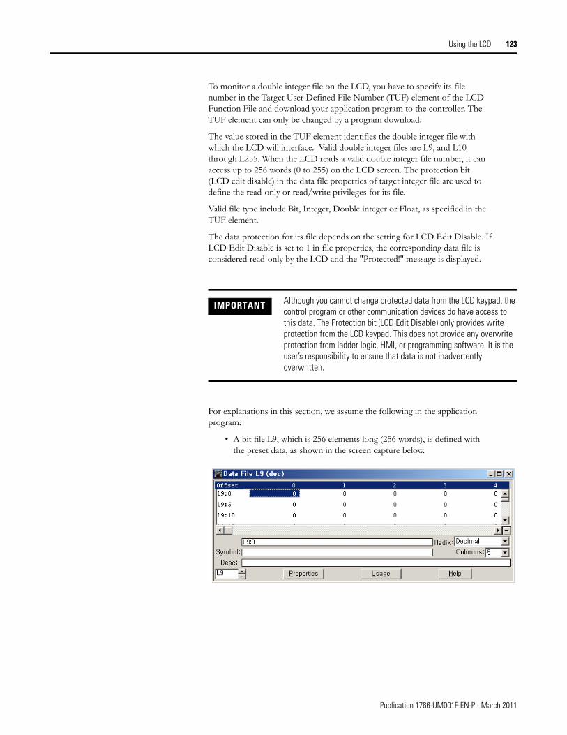
Using the LCD 123
To monitor a double integer file on the LCD, you have to specify its file number in the Target User Defined File Number (TUF) element of the LCD Function File and download your application program to the controller. The TUF element can only be changed by a program download.
The value stored in the TUF element identifies the double integer file with which the LCD will interface. Valid double integer files are L9, and L10 through L255. When the LCD reads a valid double integer file number, it can access up to 256 words (0 to 255) on the LCD screen. The protection bit (LCD edit disable) in the data file properties of target integer file are used to define the read-only or read/write privileges for its file.
Valid file type include Bit, Integer, Double integer or Float, as specified in the TUF element.
The data protection for its file depends on the setting for LCD Edit Disable. If LCD Edit Disable is set to 1 in file properties, the corresponding data file is considered read-only by the LCD and the "Protected!" message is displayed.
For explanations in this section, we assume the following in the application program:
• A bit file L9, which is 256 elements long (256 words), is defined with the preset data, as shown in the screen capture below.
IMPORTANT Although you cannot change protected data from the LCD keypad, the control program or other communication devices do have access to this data. The Protection bit (LCD Edit Disable) only provides write protection from the LCD keypad. This does not provide any overwrite protection from ladder logic, HMI, or programming software. It is the user’s responsibility to ensure that data is not inadvertently overwritten.
Publication 1766-UM001F-EN-P - March 2011
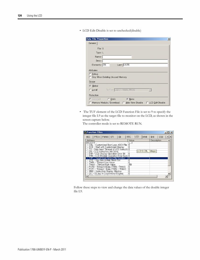
124 Using the LCD
• LCD Edit Disable is set to unchecked(disable)
• The TUF element of the LCD Function File is set to 9 to specify the integer file L9 as the target file to monitor on the LCD, as shown in the screen capture below. The controller mode is set to REMOTE RUN.
Follow these steps to view and change the data values of the double integer file L9.
Publication 1766-UM001F-EN-P - March 2011
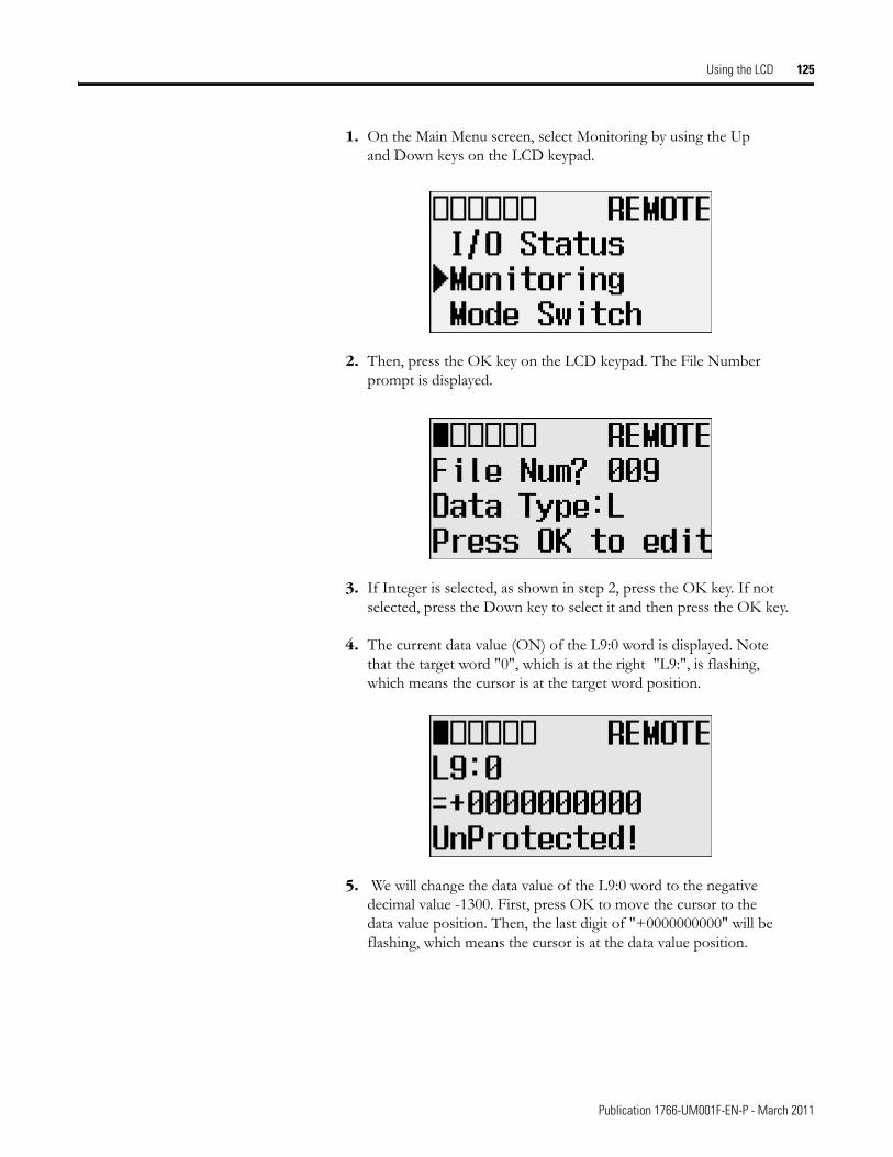
Using the LCD 125
1. On the Main Menu screen, select Monitoring by using the Up and Down keys on the LCD keypad.
2. Then, press the OK key on the LCD keypad. The File Number prompt is displayed.
3. If Integer is selected, as shown in step 2, press the OK key. If not selected, press the Down key to select it and then press the OK key.
4. The current data value (ON) of the L9:0 word is displayed. Note that the target word "0", which is at the right "L9:", is flashing, which means the cursor is at the target word position.
5. We will change the data value of the L9:0 word to the negative decimal value -1300. First, press OK to move the cursor to the data value position. Then, the last digit of "+0000000000" will be flashing, which means the cursor is at the data value position.
Publication 1766-UM001F-EN-P - March 2011
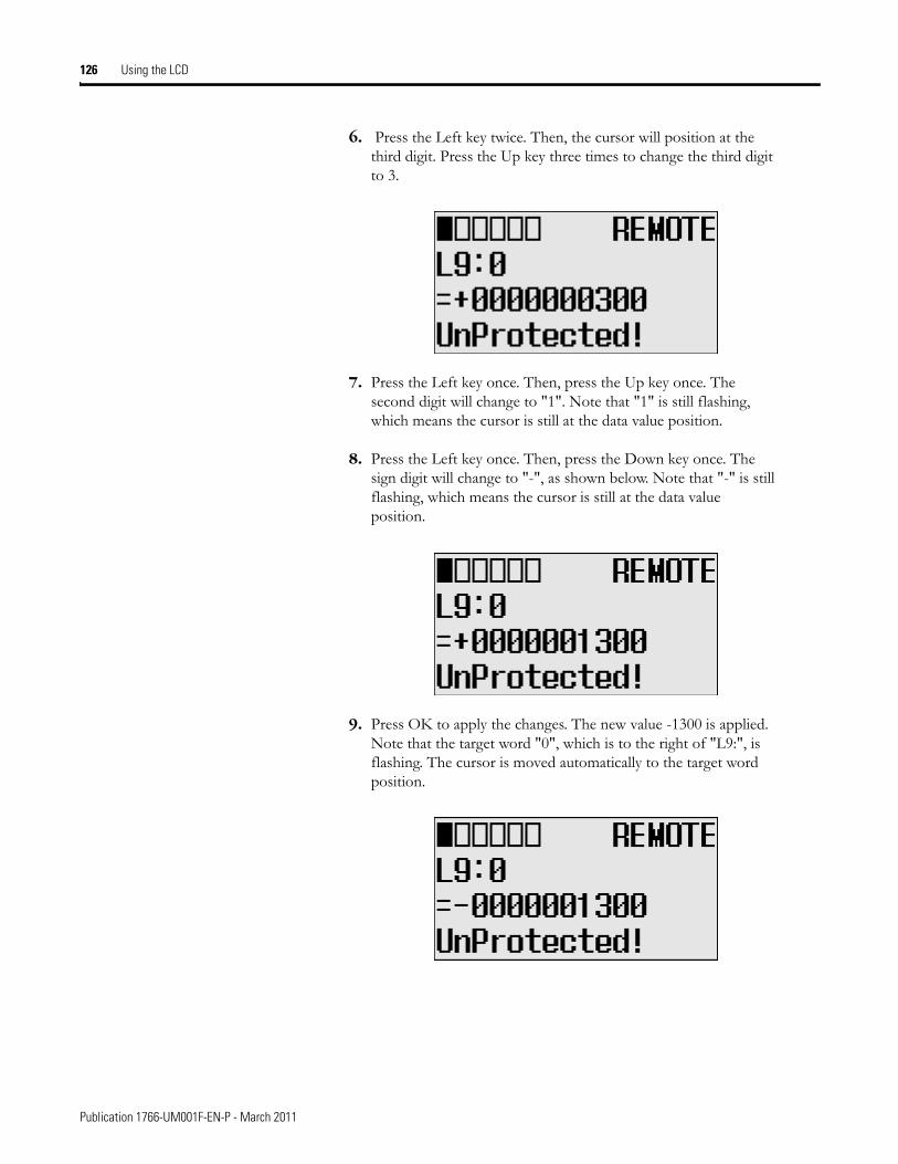
126 Using the LCD
6. Press the Left key twice. Then, the cursor will position at the third digit. Press the Up key three times to change the third digit to 3.
7. Press the Left key once. Then, press the Up key once. The second digit will change to "1". Note that "1" is still flashing, which means the cursor is still at the data value position.
8. Press the Left key once. Then, press the Down key once. The sign digit will change to "-", as shown below. Note that "-" is still flashing, which means the cursor is still at the data value position.
9. Press OK to apply the changes. The new value -1300 is applied. Note that the target word "0", which is to the right of "L9:", is flashing. The cursor is moved automatically to the target word position.
Publication 1766-UM001F-EN-P - March 2011
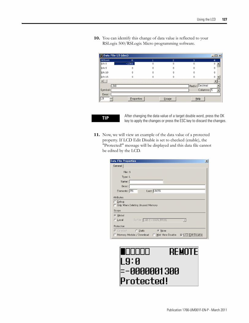
Using the LCD 127
10. You can identify this change of data value is reflected to your RSLogix 500/RSLogix Micro programming software.
11. Now, we will view an example of the data value of a protected property. If LCD Edit Disable is set to checked (enable), the "Protected!" message will be displayed and this data file cannot be edited by the LCD.
TIP After changing the data value of a target double word, press the OK key to apply the changes or press the ESC key to discard the changes.
Publication 1766-UM001F-EN-P - March 2011
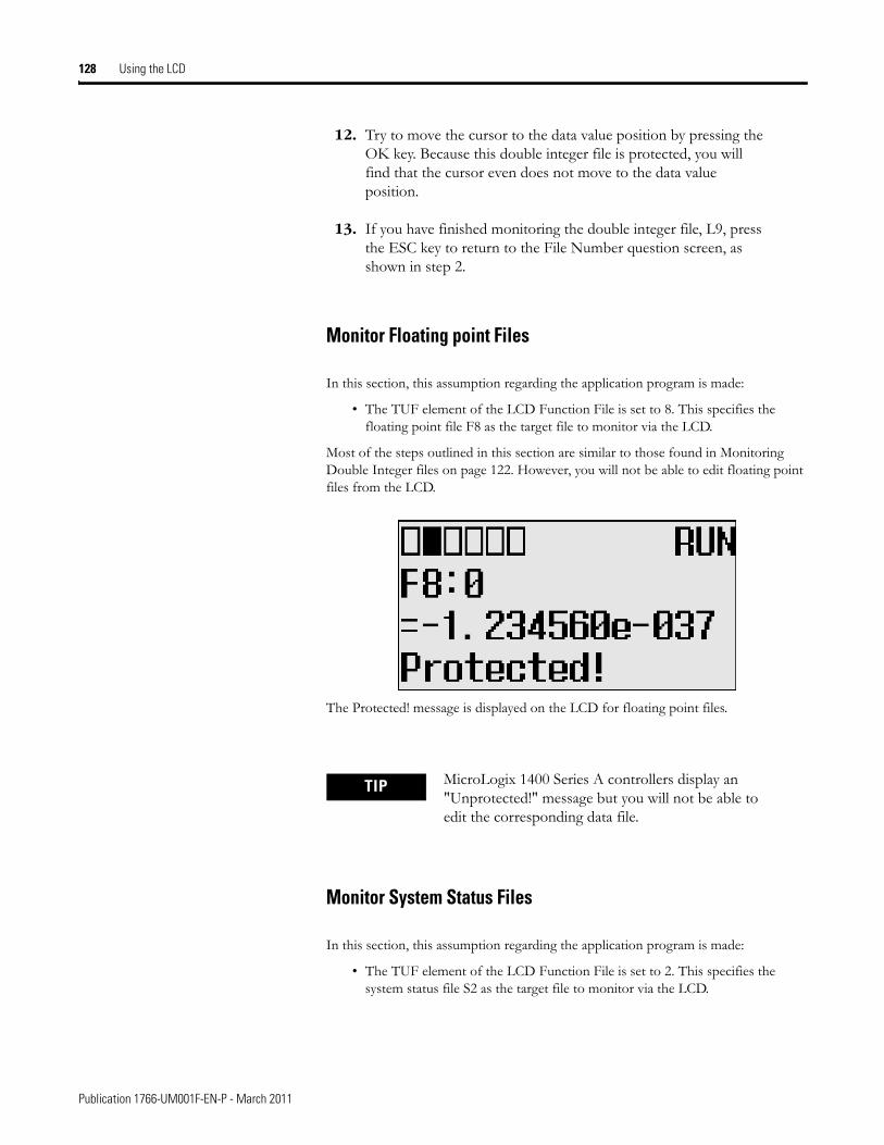
128 Using the LCD
12. Try to move the cursor to the data value position by pressing the OK key. Because this double integer file is protected, you will find that the cursor even does not move to the data value position.
13. If you have finished monitoring the double integer file, L9, press the ESC key to return to the File Number question screen, as shown in step 2.
Monitor Floating point Files
In this section, this assumption regarding the application program is made:
• The TUF element of the LCD Function File is set to 8. This specifies the floating point file F8 as the target file to monitor via the LCD.
Most of the steps outlined in this section are similar to those found in Monitoring Double Integer files on page 122. However, you will not be able to edit floating point files from the LCD.
The Protected! message is displayed on the LCD for floating point files.
Monitor System Status Files
In this section, this assumption regarding the application program is made:
• The TUF element of the LCD Function File is set to 2. This specifies the system status file S2 as the target file to monitor via the LCD.
TIP MicroLogix 1400 Series A controllers display an "Unprotected!" message but you will not be able to edit the corresponding data file.
Publication 1766-UM001F-EN-P - March 2011
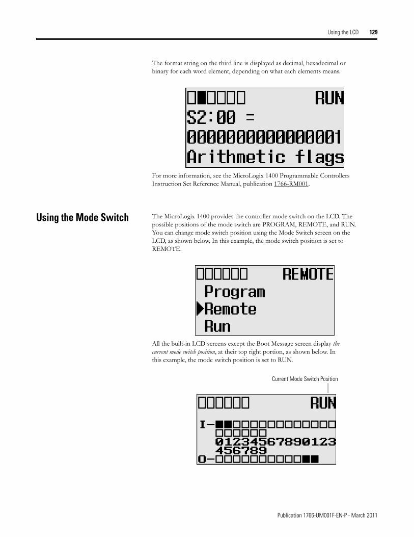
Using the LCD 129
The format string on the third line is displayed as decimal, hexadecimal or binary for each word element, depending on what each elements means.
For more information, see the MicroLogix 1400 Programmable Controllers Instruction Set Reference Manual, publication 1766-RM001.
Using the Mode Switch The MicroLogix 1400 provides the controller mode switch on the LCD. The possible positions of the mode switch are PROGRAM, REMOTE, and RUN. You can change mode switch position using the Mode Switch screen on the LCD, as shown below. In this example, the mode switch position is set to REMOTE.
All the built-in LCD screens except the Boot Message screen display the current mode switch position, at their top right portion, as shown below. In this example, the mode switch position is set to RUN.
Current Mode Switch Position
Publication 1766-UM001F-EN-P - March 2011
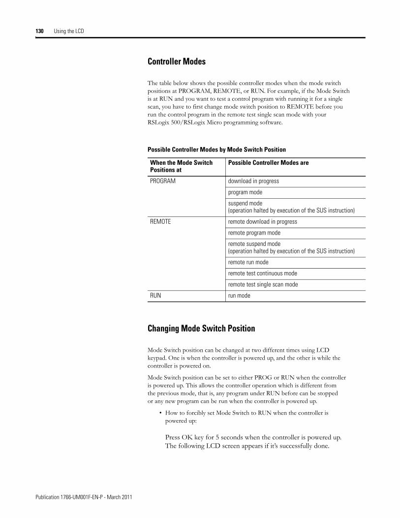
130 Using the LCD
Controller Modes
The table below shows the possible controller modes when the mode switch positions at PROGRAM, REMOTE, or RUN. For example, if the Mode Switch is at RUN and you want to test a control program with running it for a single scan, you have to first change mode switch position to REMOTE before you run the control program in the remote test single scan mode with your RSLogix 500/RSLogix Micro programming software.
Changing Mode Switch Position
Mode Switch position can be changed at two different times using LCD keypad. One is when the controller is powered up, and the other is while the controller is powered on.
Mode Switch position can be set to either PROG or RUN when the controller is powered up. This allows the controller operation which is different from the previous mode, that is, any program under RUN before can be stopped or any new program can be run when the controller is powered up.
• How to forcibly set Mode Switch to RUN when the controller is powered up:
Press OK key for 5 seconds when the controller is powered up. The following LCD screen appears if it’s successfully done.
Possible Controller Modes by Mode Switch Position
When the Mode Switch Positions at
Possible Controller Modes are
PROGRAM download in progress
program mode
suspend mode (operation halted by execution of the SUS instruction)
REMOTE remote download in progress
remote program mode
remote suspend mode (operation halted by execution of the SUS instruction)
remote run mode
remote test continuous mode
remote test single scan mode
RUN run mode
Publication 1766-UM001F-EN-P - March 2011
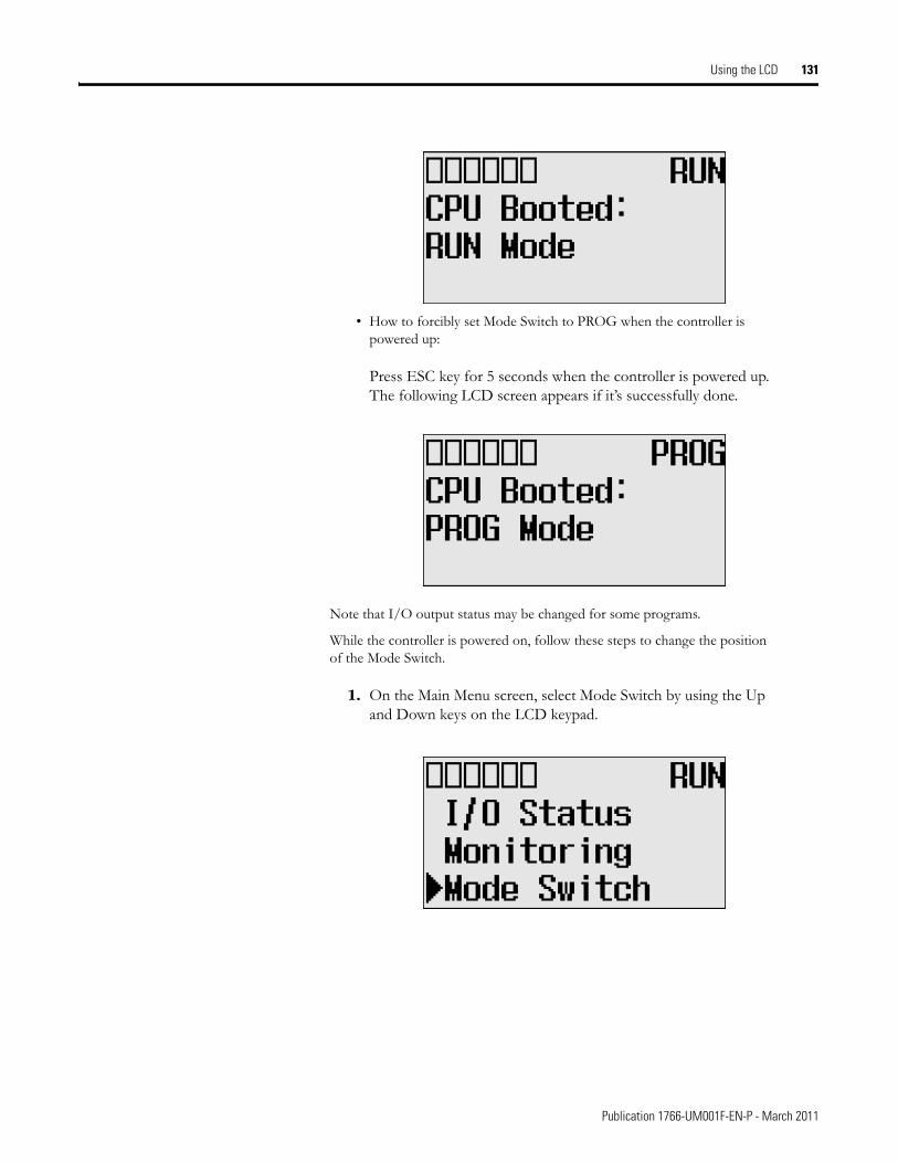
Using the LCD 131
• How to forcibly set Mode Switch to PROG when the controller is powered up:
Press ESC key for 5 seconds when the controller is powered up. The following LCD screen appears if it’s successfully done.
Note that I/O output status may be changed for some programs.
While the controller is powered on, follow these steps to change the position of the Mode Switch.
1. On the Main Menu screen, select Mode Switch by using the Up and Down keys on the LCD keypad.
Publication 1766-UM001F-EN-P - March 2011
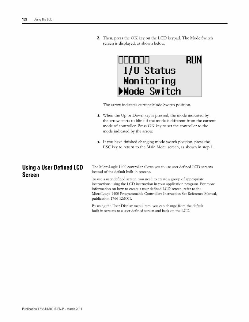
132 Using the LCD
2. Then, press the OK key on the LCD keypad. The Mode Switch screen is displayed, as shown below.
The arrow indicates current Mode Switch position.
3. When the Up or Down key is pressed, the mode indicated by the arrow starts to blink if the mode is different from the current mode of controller. Press OK key to set the controller to the mode indicated by the arrow.
4. If you have finished changing mode switch position, press the ESC key to return to the Main Menu screen, as shown in step 1.
Using a User Defined LCD Screen
The MicroLogix 1400 controller allows you to use user defined LCD screens instead of the default built-in screens.
To use a user defined screen, you need to create a group of appropriate instructions using the LCD instruction in your application program. For more information on how to create a user defined LCD screen, refer to the MicroLogix 1400 Programmable Controllers Instruction Set Reference Manual, publication 1766-RM001.
By using the User Display menu item, you can change from the default built-in screens to a user defined screen and back on the LCD.
Publication 1766-UM001F-EN-P - March 2011
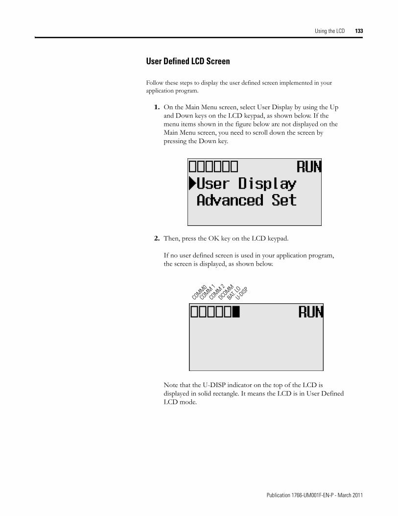
Using the LCD 133
User Defined LCD Screen
Follow these steps to display the user defined screen implemented in your application program.
1. On the Main Menu screen, select User Display by using the Up and Down keys on the LCD keypad, as shown below. If the menu items shown in the figure below are not displayed on the Main Menu screen, you need to scroll down the screen by pressing the Down key.
2. Then, press the OK key on the LCD keypad.
If no user defined screen is used in your application program, the screen is displayed, as shown below.
Note that the U-DISP indicator on the top of the LCD is displayed in solid rectangle. It means the LCD is in User Defined LCD mode.
COMM0
COMM 1
DCOMM
BAT. LO
U-DISPCOMM 2
Publication 1766-UM001F-EN-P - March 2011
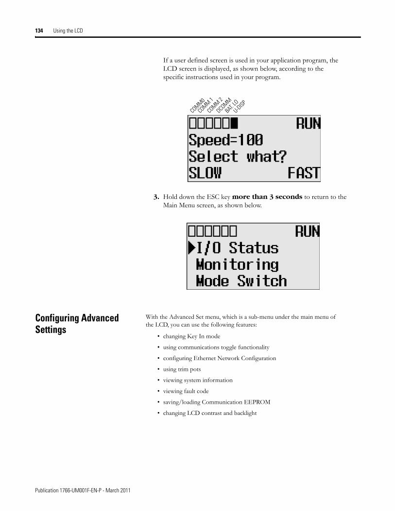
134 Using the LCD
If a user defined screen is used in your application program, the LCD screen is displayed, as shown below, according to the specific instructions used in your program.
3. Hold down the ESC key more than 3 seconds to return to the Main Menu screen, as shown below.
Configuring Advanced Settings
With the Advanced Set menu, which is a sub-menu under the main menu of the LCD, you can use the following features:
• changing Key In mode
• using communications toggle functionality
• configuring Ethernet Network Configuration
• using trim pots
• viewing system information
• viewing fault code
• saving/loading Communication EEPROM
• changing LCD contrast and backlight
COMM0
COMM 1
DCOMM
BAT. LO
U-DISPCOMM 2
Publication 1766-UM001F-EN-P - March 2011
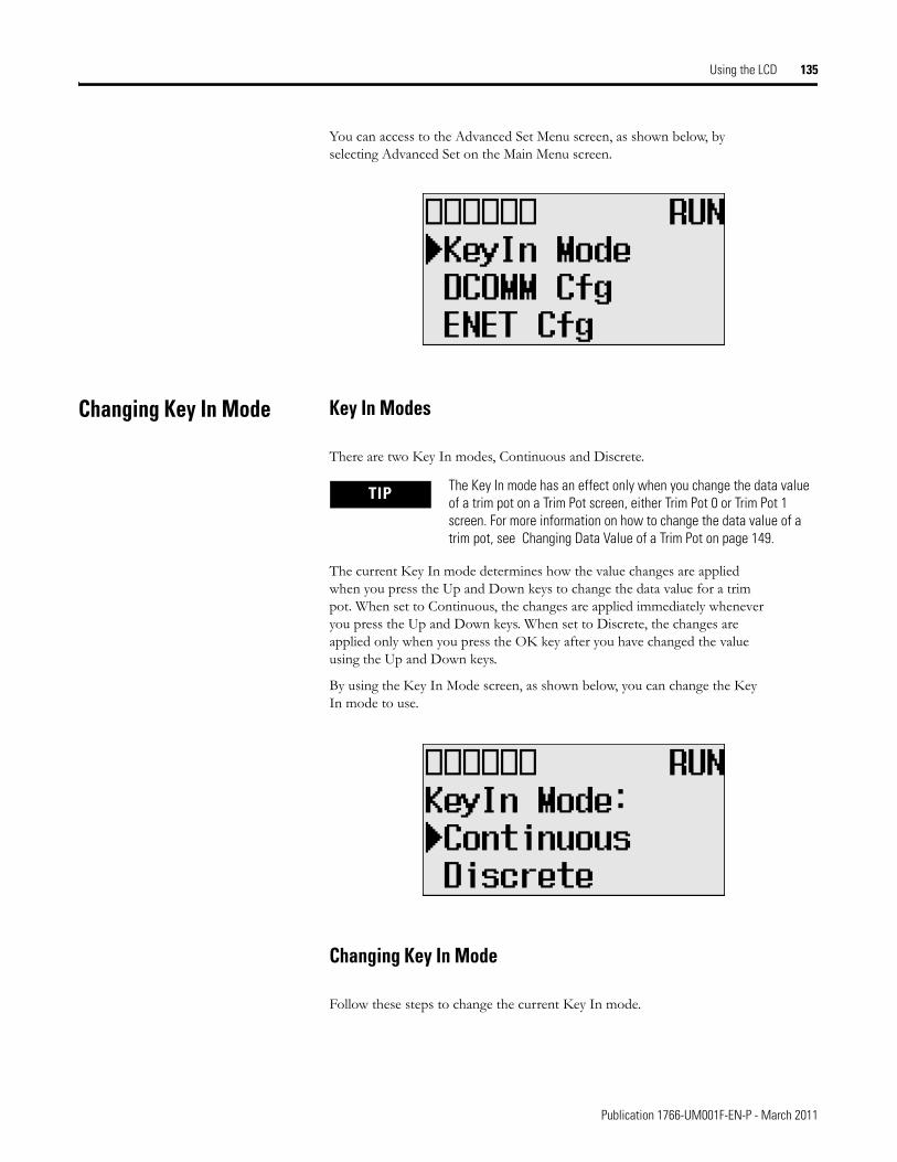
Using the LCD 135
You can access to the Advanced Set Menu screen, as shown below, by selecting Advanced Set on the Main Menu screen.
Changing Key In Mode Key In Modes
There are two Key In modes, Continuous and Discrete.
The current Key In mode determines how the value changes are applied when you press the Up and Down keys to change the data value for a trim pot. When set to Continuous, the changes are applied immediately whenever you press the Up and Down keys. When set to Discrete, the changes are applied only when you press the OK key after you have changed the value using the Up and Down keys.
By using the Key In Mode screen, as shown below, you can change the Key In mode to use.
Changing Key In Mode
Follow these steps to change the current Key In mode.
TIP The Key In mode has an effect only when you change the data value of a trim pot on a Trim Pot screen, either Trim Pot 0 or Trim Pot 1 screen. For more information on how to change the data value of a trim pot, see Changing Data Value of a Trim Pot on page 149.
Publication 1766-UM001F-EN-P - March 2011
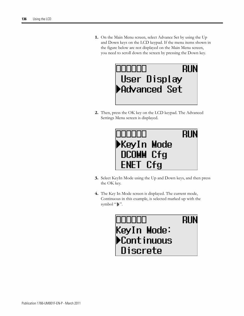
136 Using the LCD
1. On the Main Menu screen, select Advance Set by using the Up and Down keys on the LCD keypad. If the menu items shown in the figure below are not displayed on the Main Menu screen, you need to scroll down the screen by pressing the Down key.
2. Then, press the OK key on the LCD keypad. The Advanced Settings Menu screen is displayed.
3. Select KeyIn Mode using the Up and Down keys, and then press the OK key.
4. The Key In Mode screen is displayed. The current mode, Continuous in this example, is selected marked up with the symbol “ ”.
Publication 1766-UM001F-EN-P - March 2011
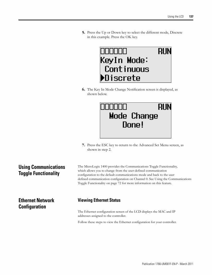
Using the LCD 137
5. Press the Up or Down key to select the different mode, Discrete in this example. Press the OK key.
6. The Key In Mode Change Notification screen is displayed, as shown below.
7. Press the ESC key to return to the Advanced Set Menu screen, as shown in step 2.
Using Communications Toggle Functionality
The MicroLogix 1400 provides the Communications Toggle Functionality, which allows you to change from the user-defined communication configuration to the default communications mode and back to the user defined communication configuration on Channel 0. See Using the Communications Toggle Functionality on page 72 for more information on this feature.
Ethernet Network Configuration
Viewing Ethernet Status
The Ethernet configuration screen of the LCD displays the MAC and IP addresses assigned to the controller.
Follow these steps to view the Ethernet configuration for your controller.
Publication 1766-UM001F-EN-P - March 2011
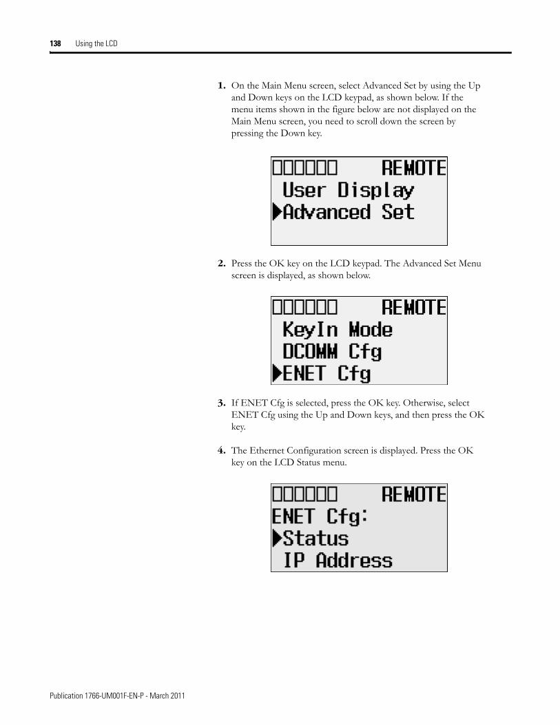
138 Using the LCD
1. On the Main Menu screen, select Advanced Set by using the Up and Down keys on the LCD keypad, as shown below. If the menu items shown in the figure below are not displayed on the Main Menu screen, you need to scroll down the screen by pressing the Down key.
2. Press the OK key on the LCD keypad. The Advanced Set Menu screen is displayed, as shown below.
3. If ENET Cfg is selected, press the OK key. Otherwise, select ENET Cfg using the Up and Down keys, and then press the OK key.
4. The Ethernet Configuration screen is displayed. Press the OK key on the LCD Status menu.
Publication 1766-UM001F-EN-P - March 2011
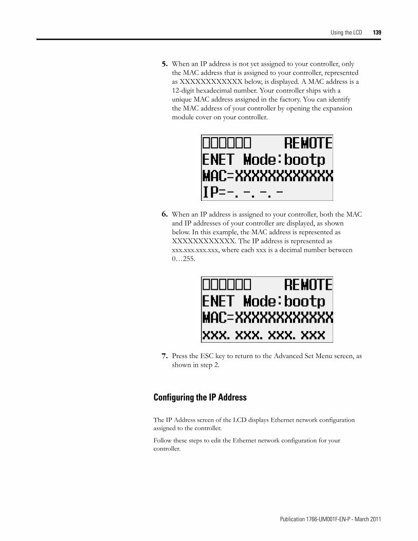
Using the LCD 139
5. When an IP address is not yet assigned to your controller, only the MAC address that is assigned to your controller, represented as XXXXXXXXXXXX below, is displayed. A MAC address is a 12-digit hexadecimal number. Your controller ships with a unique MAC address assigned in the factory. You can identify the MAC address of your controller by opening the expansion module cover on your controller.
6. When an IP address is assigned to your controller, both the MAC and IP addresses of your controller are displayed, as shown below. In this example, the MAC address is represented as XXXXXXXXXXXX. The IP address is represented as xxx.xxx.xxx.xxx, where each xxx is a decimal number between 0…255.
7. Press the ESC key to return to the Advanced Set Menu screen, as shown in step 2.
Configuring the IP Address
The IP Address screen of the LCD displays Ethernet network configuration assigned to the controller.
Follow these steps to edit the Ethernet network configuration for your controller.
Publication 1766-UM001F-EN-P - March 2011
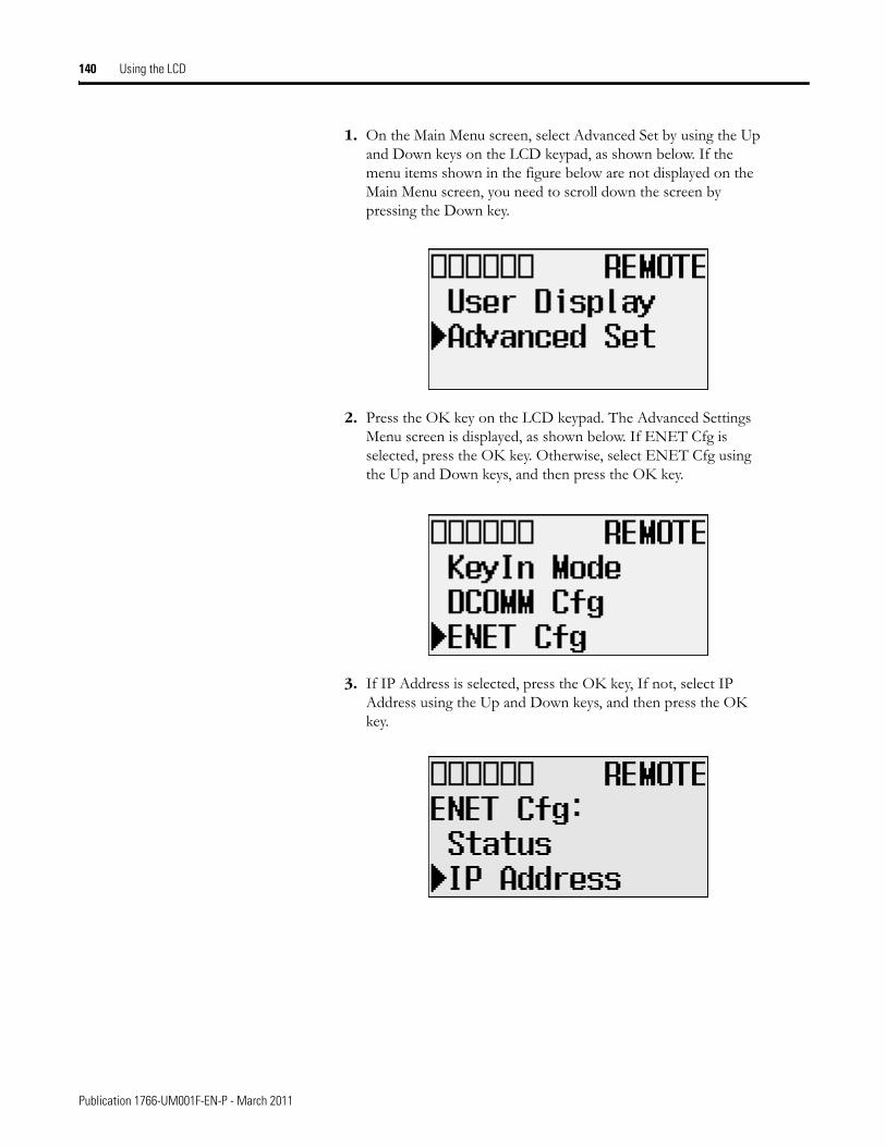
140 Using the LCD
1. On the Main Menu screen, select Advanced Set by using the Up and Down keys on the LCD keypad, as shown below. If the menu items shown in the figure below are not displayed on the Main Menu screen, you need to scroll down the screen by pressing the Down key.
2. Press the OK key on the LCD keypad. The Advanced Settings Menu screen is displayed, as shown below. If ENET Cfg is selected, press the OK key. Otherwise, select ENET Cfg using the Up and Down keys, and then press the OK key.
3. If IP Address is selected, press the OK key, If not, select IP Address using the Up and Down keys, and then press the OK key.
Publication 1766-UM001F-EN-P - March 2011
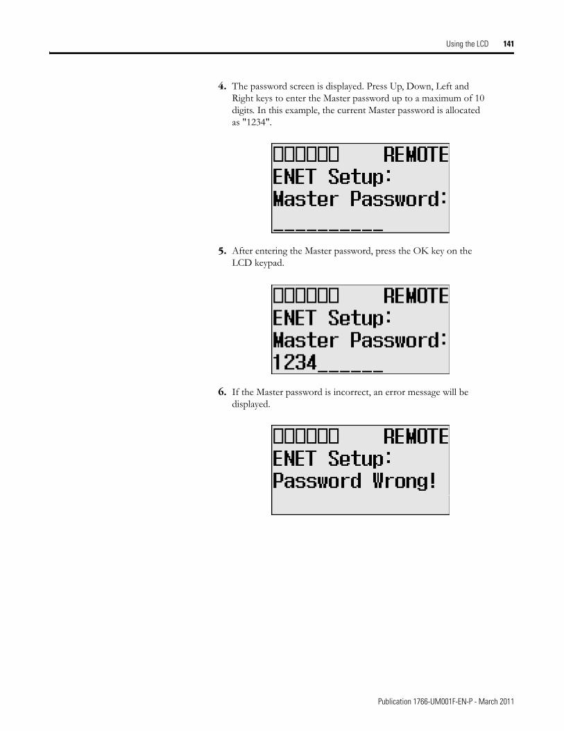
Using the LCD 141
4. The password screen is displayed. Press Up, Down, Left and Right keys to enter the Master password up to a maximum of 10 digits. In this example, the current Master password is allocated as "1234".
5. After entering the Master password, press the OK key on the LCD keypad.
6. If the Master password is incorrect, an error message will be displayed.
Publication 1766-UM001F-EN-P - March 2011
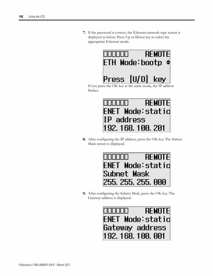
142 Using the LCD
7. If the password is correct, the Ethernet network type screen is displayed as below. Press Up or Down key to select the appropriate Ethernet mode.
If you press the OK key at the static mode, the IP address flashes.
8. After configuring the IP address, press the OK key. The Subnet Mask screen is displayed.
9. After configuring the Subnet Mask, press the OK key. The Gateway address is displayed.
Publication 1766-UM001F-EN-P - March 2011
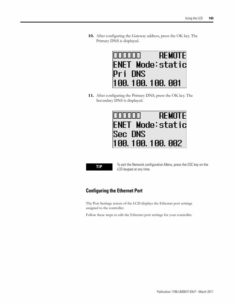
Using the LCD 143
10. After configuring the Gateway address, press the OK key. The Primary DNS is displayed.
11. After configuring the Primary DNS, press the OK key. The Secondary DNS is displayed.
Configuring the Ethernet Port
The Port Settings screen of the LCD displays the Ethernet port settings assigned to the controller.
Follow these steps to edit the Ethernet port settings for your controller.
TIP To exit the Network configuration Menu, press the ESC key on the LCD keypad at any time.
Publication 1766-UM001F-EN-P - March 2011
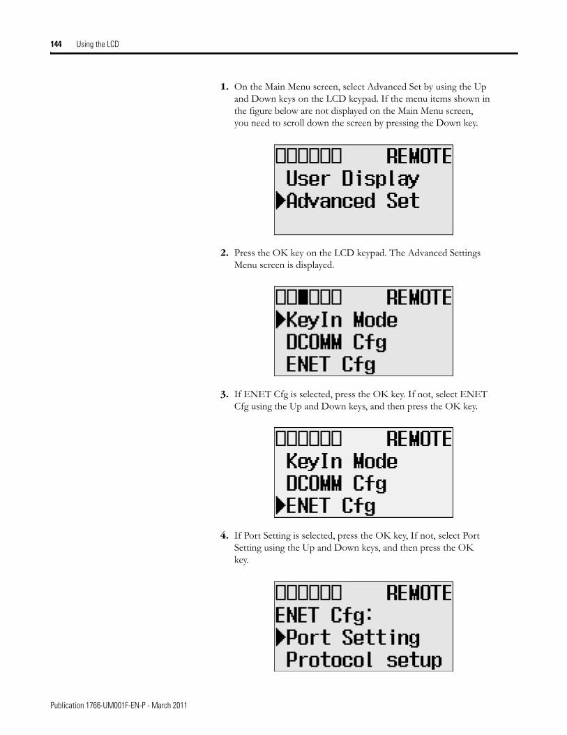
144 Using the LCD
1. On the Main Menu screen, select Advanced Set by using the Up and Down keys on the LCD keypad. If the menu items shown in the figure below are not displayed on the Main Menu screen, you need to scroll down the screen by pressing the Down key.
2. Press the OK key on the LCD keypad. The Advanced Settings Menu screen is displayed.
3. If ENET Cfg is selected, press the OK key. If not, select ENET Cfg using the Up and Down keys, and then press the OK key.
4. If Port Setting is selected, press the OK key, If not, select Port Setting using the Up and Down keys, and then press the OK key.
Publication 1766-UM001F-EN-P - March 2011
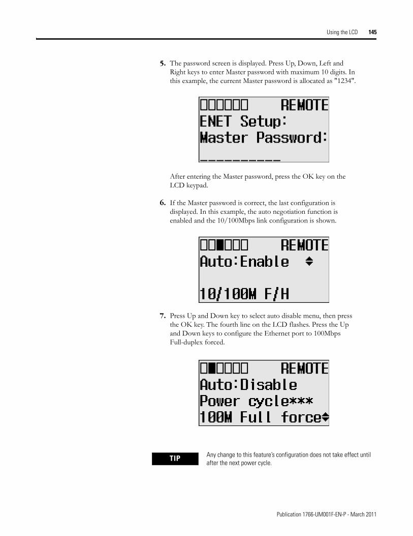
Using the LCD 145
5. The password screen is displayed. Press Up, Down, Left and Right keys to enter Master password with maximum 10 digits. In this example, the current Master password is allocated as "1234".
After entering the Master password, press the OK key on the LCD keypad.
6. If the Master password is correct, the last configuration is displayed. In this example, the auto negotiation function is enabled and the 10/100Mbps link configuration is shown.
7. Press Up and Down key to select auto disable menu, then press the OK key. The fourth line on the LCD flashes. Press the Up and Down keys to configure the Ethernet port to 100Mbps Full-duplex forced.
TIP Any change to this feature’s configuration does not take effect until after the next power cycle.
Publication 1766-UM001F-EN-P - March 2011
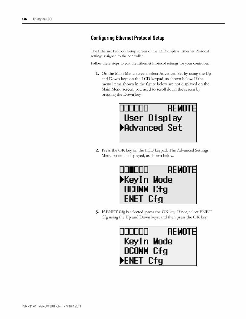
146 Using the LCD
Configuring Ethernet Protocol Setup
The Ethernet Protocol Setup screen of the LCD displays Ethernet Protocol settings assigned to the controller.
Follow these steps to edit the Ethernet Protocol settings for your controller.
1. On the Main Menu screen, select Advanced Set by using the Up and Down keys on the LCD keypad, as shown below. If the menu items shown in the figure below are not displayed on the Main Menu screen, you need to scroll down the screen by pressing the Down key.
2. Press the OK key on the LCD keypad. The Advanced Settings Menu screen is displayed, as shown below.
3. If ENET Cfg is selected, press the OK key. If not, select ENET Cfg using the Up and Down keys, and then press the OK key.
Publication 1766-UM001F-EN-P - March 2011
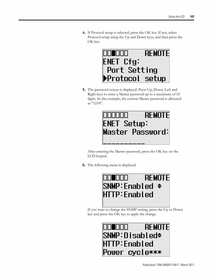
Using the LCD 147
4. If Protocol setup is selected, press the OK key. If not, select Protocol setup using the Up and Down keys, and then press the OK key.
5. The password screen is displayed. Press Up, Down, Left and Right keys to enter a Master password up to a maximum of 10 digits. In this example, the current Master password is allocated as "1234".
After entering the Master password, press the OK key on the LCD keypad.
6. The following menu is displayed.
If you want to change the SNMP setting, press the Up or Down key and press the OK key to apply the change.
Publication 1766-UM001F-EN-P - March 2011
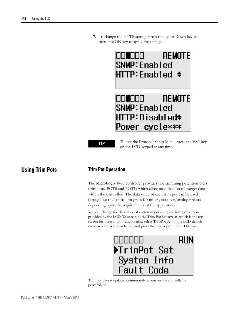
148 Using the LCD
7. To change the HTTP setting, press the Up or Down key and press the OK key to apply the change.
Using Trim Pots Trim Pot Operation
The MicroLogix 1400 controller provides two trimming potentiometers (trim pots, POT0 and POT1) which allow modification of integer data within the controller. The data value of each trim pot can be used throughout the control program for timers, counters, analog presets, depending upon the requirements of the application.
You can change the data value of each trim pot using the trim pot screens provided by the LCD. To access to the Trim Pot Set screen, which is the top screen for the trim pot functionality, select TrimPot Set on the LCD default menu screen, as shown below, and press the OK key on the LCD keypad.
Trim pot data is updated continuously whenever the controller is powered-up.
TIP To exit the Protocol Setup Menu, press the ESC key on the LCD keypad at any time.
Publication 1766-UM001F-EN-P - March 2011
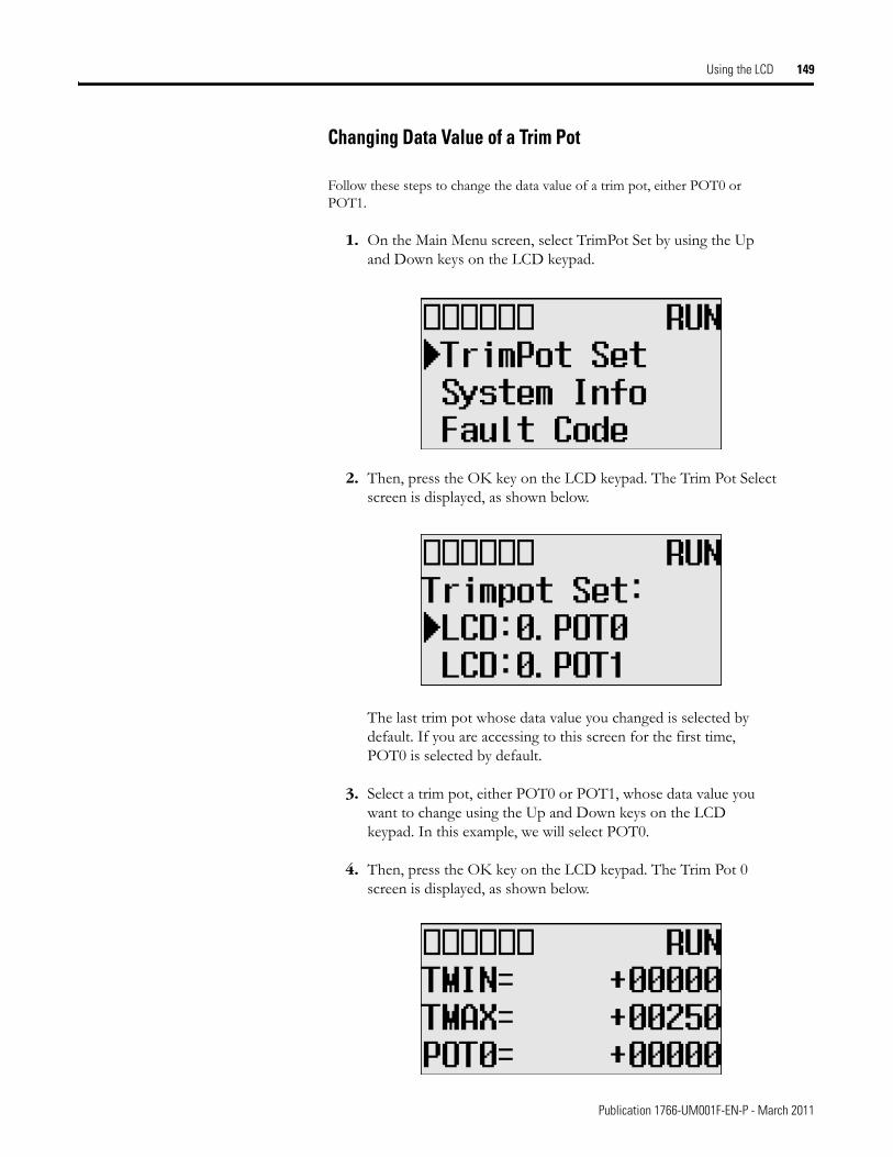
Using the LCD 149
Changing Data Value of a Trim Pot
Follow these steps to change the data value of a trim pot, either POT0 or POT1.
1. On the Main Menu screen, select TrimPot Set by using the Up and Down keys on the LCD keypad.
2. Then, press the OK key on the LCD keypad. The Trim Pot Select screen is displayed, as shown below.
The last trim pot whose data value you changed is selected by default. If you are accessing to this screen for the first time, POT0 is selected by default.
3. Select a trim pot, either POT0 or POT1, whose data value you want to change using the Up and Down keys on the LCD keypad. In this example, we will select POT0.
4. Then, press the OK key on the LCD keypad. The Trim Pot 0 screen is displayed, as shown below.
Publication 1766-UM001F-EN-P - March 2011
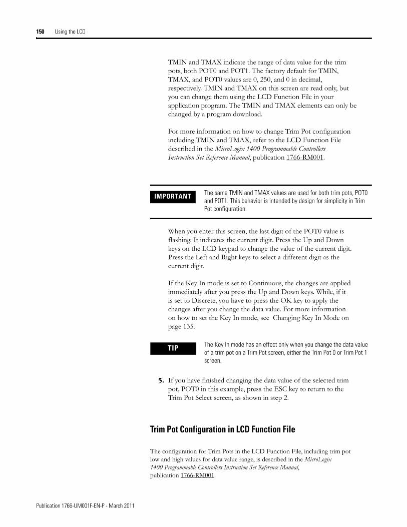
150 Using the LCD
TMIN and TMAX indicate the range of data value for the trim pots, both POT0 and POT1. The factory default for TMIN, TMAX, and POT0 values are 0, 250, and 0 in decimal, respectively. TMIN and TMAX on this screen are read only, but you can change them using the LCD Function File in your application program. The TMIN and TMAX elements can only be changed by a program download.
For more information on how to change Trim Pot configuration including TMIN and TMAX, refer to the LCD Function File described in the MicroLogix 1400 Programmable Controllers Instruction Set Reference Manual, publication 1766-RM001.
When you enter this screen, the last digit of the POT0 value is flashing. It indicates the current digit. Press the Up and Down keys on the LCD keypad to change the value of the current digit. Press the Left and Right keys to select a different digit as the current digit.
If the Key In mode is set to Continuous, the changes are applied immediately after you press the Up and Down keys. While, if it is set to Discrete, you have to press the OK key to apply the changes after you change the data value. For more information on how to set the Key In mode, see Changing Key In Mode on page 135.
5. If you have finished changing the data value of the selected trim pot, POT0 in this example, press the ESC key to return to the Trim Pot Select screen, as shown in step 2.
Trim Pot Configuration in LCD Function File
The configuration for Trim Pots in the LCD Function File, including trim pot low and high values for data value range, is described in the MicroLogix 1400 Programmable Controllers Instruction Set Reference Manual, publication 1766-RM001.
IMPORTANT The same TMIN and TMAX values are used for both trim pots, POT0 and POT1. This behavior is intended by design for simplicity in Trim Pot configuration.
TIP The Key In mode has an effect only when you change the data value of a trim pot on a Trim Pot screen, either the Trim Pot 0 or Trim Pot 1 screen.
Publication 1766-UM001F-EN-P - March 2011
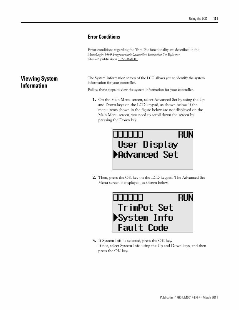
Using the LCD 151
Error Conditions
Error conditions regarding the Trim Pot functionality are described in the MicroLogix 1400 Programmable Controllers Instruction Set Reference Manual, publication 1766-RM001.
Viewing System Information
The System Information screen of the LCD allows you to identify the system information for your controller.
Follow these steps to view the system information for your controller.
1. On the Main Menu screen, select Advanced Set by using the Up and Down keys on the LCD keypad, as shown below. If the menu items shown in the figure below are not displayed on the Main Menu screen, you need to scroll down the screen by pressing the Down key.
2. Then, press the OK key on the LCD keypad. The Advanced Set Menu screen is displayed, as shown below.
3. If System Info is selected, press the OK key. If not, select System Info using the Up and Down keys, and then press the OK key.
Publication 1766-UM001F-EN-P - March 2011
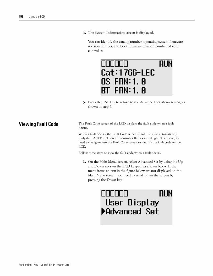
152 Using the LCD
4. The System Information screen is displayed.
You can identify the catalog number, operating system firmware revision number, and boot firmware revision number of your controller.
5. Press the ESC key to return to the Advanced Set Menu screen, as shown in step 3.
Viewing Fault Code The Fault Code screen of the LCD displays the fault code when a fault occurs.
When a fault occurs, the Fault Code screen is not displayed automatically. Only the FAULT LED on the controller flashes in red light. Therefore, you need to navigate into the Fault Code screen to identify the fault code on the LCD.
Follow these steps to view the fault code when a fault occurs.
1. On the Main Menu screen, select Advanced Set by using the Up and Down keys on the LCD keypad, as shown below. If the menu items shown in the figure below are not displayed on the Main Menu screen, you need to scroll down the screen by pressing the Down key.
Publication 1766-UM001F-EN-P - March 2011
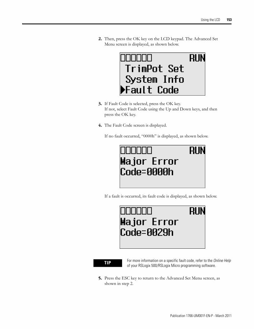
Using the LCD 153
2. Then, press the OK key on the LCD keypad. The Advanced Set Menu screen is displayed, as shown below.
3. If Fault Code is selected, press the OK key. If not, select Fault Code using the Up and Down keys, and then press the OK key.
4. The Fault Code screen is displayed.
If no fault occurred, “0000h” is displayed, as shown below.
If a fault is occurred, its fault code is displayed, as shown below.
5. Press the ESC key to return to the Advanced Set Menu screen, as shown in step 2.
TIP For more information on a specific fault code, refer to the Online Help of your RSLogix 500/RSLogix Micro programming software.
Publication 1766-UM001F-EN-P - March 2011
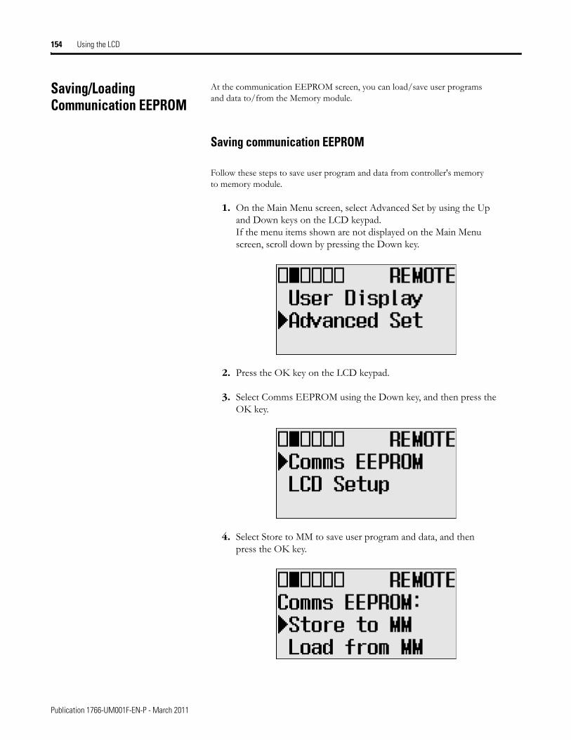
154 Using the LCD
Saving/Loading Communication EEPROM
At the communication EEPROM screen, you can load/save user programs and data to/from the Memory module.
Saving communication EEPROM
Follow these steps to save user program and data from controller's memory to memory module.
1. On the Main Menu screen, select Advanced Set by using the Up and Down keys on the LCD keypad. If the menu items shown are not displayed on the Main Menu screen, scroll down by pressing the Down key.
2. Press the OK key on the LCD keypad.
3. Select Comms EEPROM using the Down key, and then press the OK key.
4. Select Store to MM to save user program and data, and then press the OK key.
Publication 1766-UM001F-EN-P - March 2011
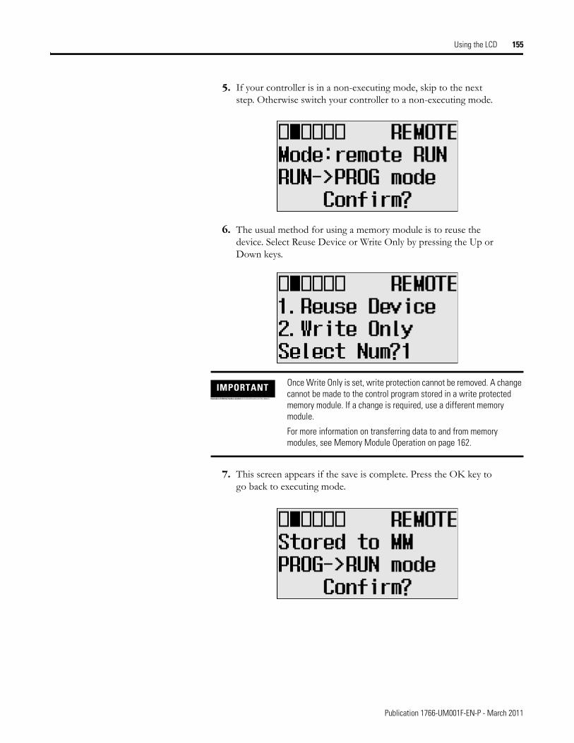
Using the LCD 155
5. If your controller is in a non-executing mode, skip to the next step. Otherwise switch your controller to a non-executing mode.
6. The usual method for using a memory module is to reuse the device. Select Reuse Device or Write Only by pressing the Up or Down keys.
7. This screen appears if the save is complete. Press the OK key to go back to executing mode.
IMPORTANTOnce set to Write Only mode, write protection cannot be removed. If a change is required, use a different memory module. For more information on this, refer to the chapter of Memory Module operation.
Once Write Only is set, write protection cannot be removed. A change cannot be made to the control program stored in a write protected memory module. If a change is required, use a different memory module.
For more information on transferring data to and from memory modules, see Memory Module Operation on page 162.
Publication 1766-UM001F-EN-P - March 2011
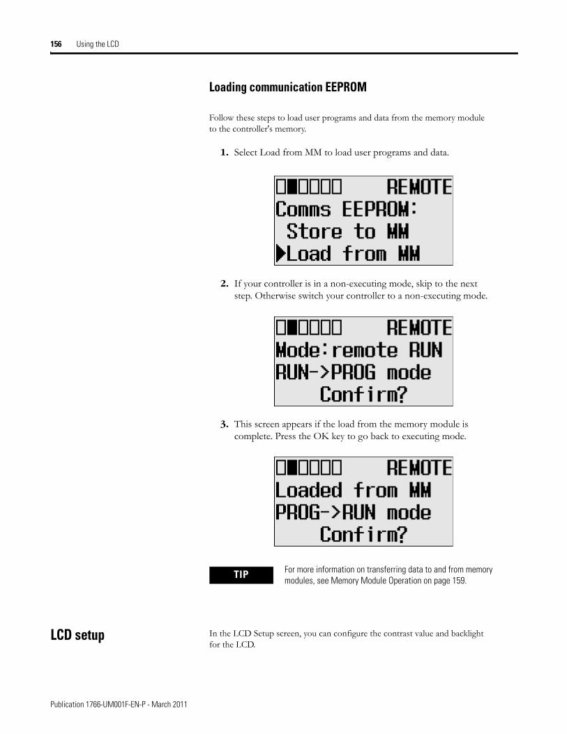
156 Using the LCD
Loading communication EEPROM
Follow these steps to load user programs and data from the memory module to the controller's memory.
1. Select Load from MM to load user programs and data.
2. If your controller is in a non-executing mode, skip to the next step. Otherwise switch your controller to a non-executing mode.
3. This screen appears if the load from the memory module is complete. Press the OK key to go back to executing mode.
LCD setup In the LCD Setup screen, you can configure the contrast value and backlight for the LCD.
TIP For more information on transferring data to and from memory modules, see Memory Module Operation on page 159.
Publication 1766-UM001F-EN-P - March 2011
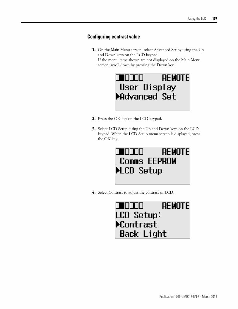
Using the LCD 157
Configuring contrast value
1. On the Main Menu screen, select Advanced Set by using the Up and Down keys on the LCD keypad. If the menu items shown are not displayed on the Main Menu screen, scroll down by pressing the Down key.
2. Press the OK key on the LCD keypad.
3. Select LCD Setup, using the Up and Down keys on the LCD keypad. When the LCD Setup menu screen is displayed, press the OK key.
4. Select Contrast to adjust the contrast of LCD.
Publication 1766-UM001F-EN-P - March 2011
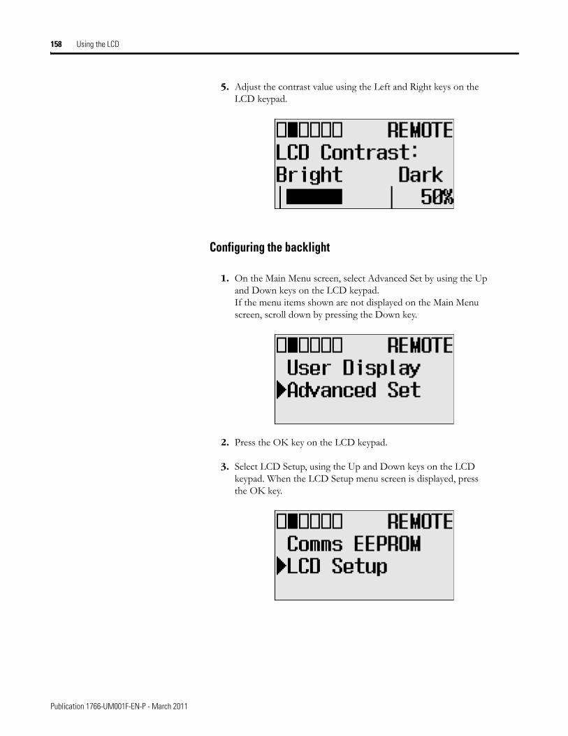
158 Using the LCD
5. Adjust the contrast value using the Left and Right keys on the LCD keypad.
Configuring the backlight
1. On the Main Menu screen, select Advanced Set by using the Up and Down keys on the LCD keypad. If the menu items shown are not displayed on the Main Menu screen, scroll down by pressing the Down key.
2. Press the OK key on the LCD keypad.
3. Select LCD Setup, using the Up and Down keys on the LCD keypad. When the LCD Setup menu screen is displayed, press the OK key.
Publication 1766-UM001F-EN-P - March 2011
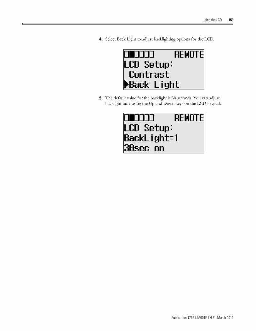
Using the LCD 159
4. Select Back Light to adjust backlighting options for the LCD.
5. The default value for the backlight is 30 seconds. You can adjust backlight time using the Up and Down keys on the LCD keypad.
Publication 1766-UM001F-EN-P - March 2011

160 Using the LCD
Notes:
Publication 1766-UM001F-EN-P - March 2011
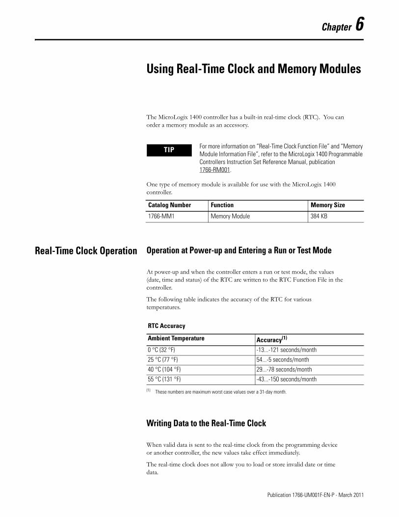
Chapter 6
Using Real-Time Clock and Memory Modules
The MicroLogix 1400 controller has a built-in real-time clock (RTC). You can order a memory module as an accessory.
One type of memory module is available for use with the MicroLogix 1400 controller.
Real-Time Clock Operation Operation at Power-up and Entering a Run or Test Mode
At power-up and when the controller enters a run or test mode, the values (date, time and status) of the RTC are written to the RTC Function File in the controller.
The following table indicates the accuracy of the RTC for various temperatures.
Writing Data to the Real-Time Clock
When valid data is sent to the real-time clock from the programming device or another controller, the new values take effect immediately.
The real-time clock does not allow you to load or store invalid date or time data.
TIP For more information on “Real-Time Clock Function File” and “Memory Module Information File”, refer to the MicroLogix 1400 Programmable Controllers Instruction Set Reference Manual, publication 1766-RM001.
Catalog Number Function Memory Size
1766-MM1 Memory Module 384 KB
RTC Accuracy
Ambient Temperature Accuracy(1)
(1) These numbers are maximum worst case values over a 31-day month.
0 °C (32 °F) -13...-121 seconds/month
25 °C (77 °F) 54...-5 seconds/month
40 °C (104 °F) 29...-78 seconds/month
55 °C (131 °F) -43...-150 seconds/month
161 Publication 1766-UM001F-EN-P - March 2011
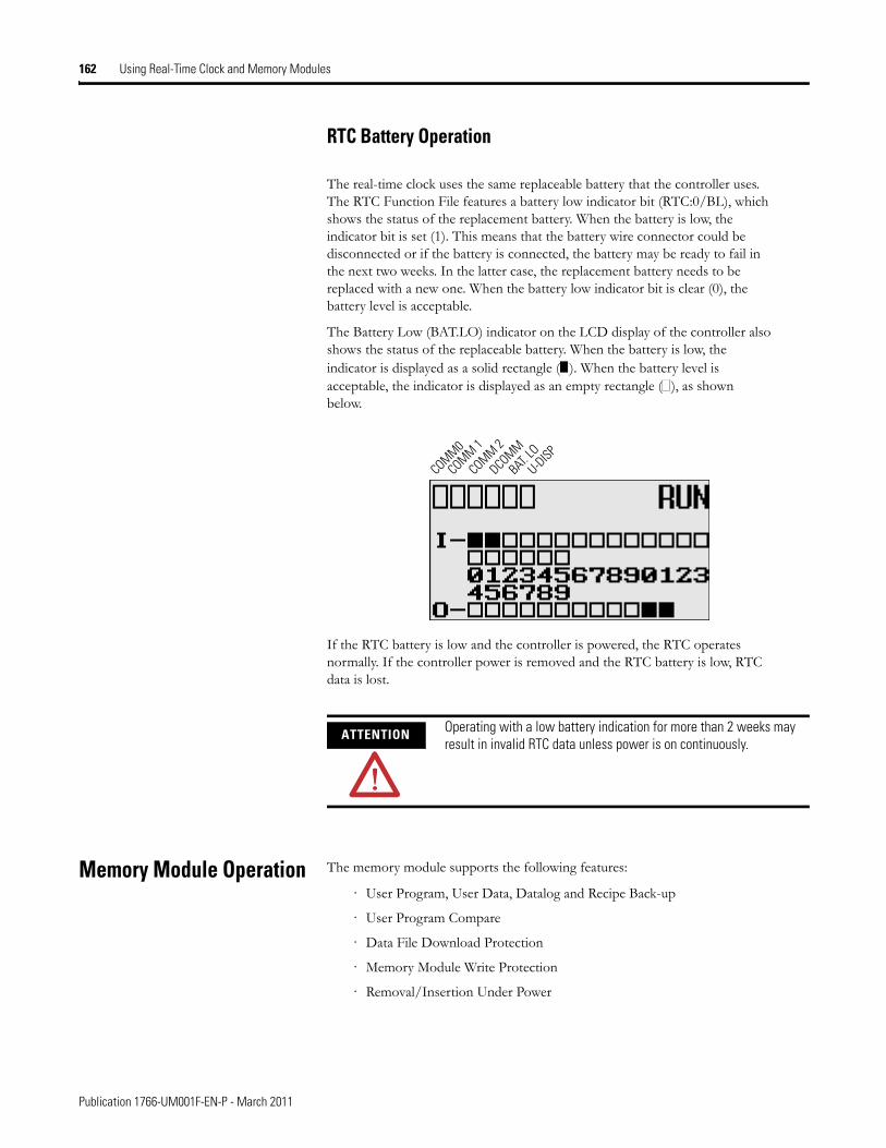
162 Using Real-Time Clock and Memory Modules
RTC Battery Operation
The real-time clock uses the same replaceable battery that the controller uses. The RTC Function File features a battery low indicator bit (RTC:0/BL), which shows the status of the replacement battery. When the battery is low, the indicator bit is set (1). This means that the battery wire connector could be disconnected or if the battery is connected, the battery may be ready to fail in the next two weeks. In the latter case, the replacement battery needs to be replaced with a new one. When the battery low indicator bit is clear (0), the battery level is acceptable.
The Battery Low (BAT.LO) indicator on the LCD display of the controller also shows the status of the replaceable battery. When the battery is low, the indicator is displayed as a solid rectangle ( ). When the battery level is acceptable, the indicator is displayed as an empty rectangle ( ), as shown below.
If the RTC battery is low and the controller is powered, the RTC operates normally. If the controller power is removed and the RTC battery is low, RTC data is lost.
Memory Module Operation The memory module supports the following features:
· User Program, User Data, Datalog and Recipe Back-up
· User Program Compare
· Data File Download Protection
· Memory Module Write Protection
· Removal/Insertion Under Power
ATTENTION Operating with a low battery indication for more than 2 weeks may result in invalid RTC data unless power is on continuously.
COMM0
COMM 1
DCOMM
BAT. LO
U-DISPCOMM 2
Publication 1766-UM001F-EN-P - March 2011
Using Real-Time Clock and Memory Modules 163
User Program , User Data, Datalog and Recipe Back-up
The memory module provides a simple and flexible program, data, DataLog, and Recipe transport mechanism, allowing the user to transfer the program, data, DataLog and Recipe to the controller without the use of a personal computer and programming software.
The memory module can store one user program at a time.
During program transfers to or from the memory module, the controller’s RUN LED flashes.
Program Compare
The memory module can also provide application security, allowing you to specify that if the program stored in the memory module does not match the program in the controller, the controller will not enter an executing (run or test) mode. To enable this feature, set the S:2/9 bit in the system status file. See “Status System File” in the MicroLogix 1400 Programmable Controllers Instruction Set Reference Manual, Publication 1766-RM001 for more information.
Data File Download Protection
The memory module supports data file download protection. This allows user data to be saved (not overwritten) during a download.
ATTENTION Electrostatic discharge can damage the Memory Module. Do not touch the connector pins or other sensitive areas.
TIP Data file download protection is only functional if the processor does not have a fault, size of all protected data files in the memory module exactly match the size of protected data files within the controller, and all protected data files are of the same type. See “Protecting Data Files During Download” in the MicroLogix 1400 Programmable Controllers Instruction Set Reference Manual, Publication 1766-RM001.
Publication 1766-UM001F-EN-P - March 2011
164 Using Real-Time Clock and Memory Modules
Memory Module Write Protection
The memory module supports write-once, read-many behavior. Write protection is enabled using your programming software.
Removal/Insertion Under Power
The memory module can be installed or removed without risk of damage to either the memory module or the controller, except during a data transaction. If the memory module is removed during a data transaction, data corruption can occur.If a memory module is installed while the MicroLogix 1400 is executing, the memory module is not recognized until either a power cycle occurs, or until the controller is placed in a non-executing mode (program mode, suspend mode or fault condition).
Memory Module Information File
The controller has a Memory Module Information (MMI) File which provides status from the attached memory module. At power-up or on detection of a memory module being inserted, the catalog number, series, revision, and type are identified and written to the MMI file. If a memory module is not attached, zeros are written to the MMI file. Refer to the MicroLogix 1400 Instruction Set Reference Manual, publication 1766-RM001, for more information.
Program /Data Download
To download the program and data from a memory module to the controller’s memory, on the “Comms” menu in your RSLogix 500/RSLogix Micro programming software, point “EEPROM” and then click “Load from EEPROM”.
IMPORTANT Once set, write protection cannot be removed. A change cannot be made to the control program stored in a write protected memory module. If a change is required, use a different memory module.
TIP With MicroLogix 1400, you can also use the LCD and the LCD buttons on the module to transfer applications to or from the controller.
For more information on program/data download, refer to your RSLogix 500/RSLogix Micro programming software documentation.
Publication 1766-UM001F-EN-P - March 2011

Using Real-Time Clock and Memory Modules 165
Program /Data Upload
To upload the program and data from the controller’s memory to a memory module, on the “Comms” menu in your RSLogix 500/RSLogix Micro programming software, point “EEPROM” and then click “Store to EEPROM”.
TIP With MicroLogix 1400, you can also use the LCD and the LCD buttons on the module to transfer applications to or from the controller.
For more information on program/data upload, refer to your RSLogix 500/RSLogix Micro programming software documentation.
Publication 1766-UM001F-EN-P - March 2011

166 Using Real-Time Clock and Memory Modules
Notes:
Publication 1766-UM001F-EN-P - March 2011
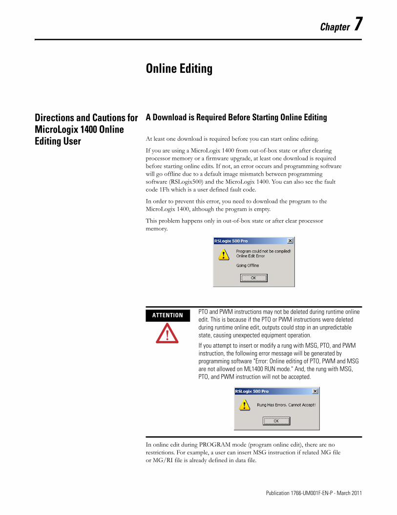
Chapter 7
Online Editing
Directions and Cautions for MicroLogix 1400 Online Editing User
A Download is Required Before Starting Online Editing
At least one download is required before you can start online editing.
If you are using a MicroLogix 1400 from out-of-box state or after clearing processor memory or a firmware upgrade, at least one download is required before starting online edits. If not, an error occurs and programming software will go offline due to a default image mismatch between programming software (RSLogix500) and the MicroLogix 1400. You can also see the fault code 1Fh which is a user defined fault code.
In order to prevent this error, you need to download the program to the MicroLogix 1400, although the program is empty.
This problem happens only in out-of-box state or after clear processor memory.
In online edit during PROGRAM mode (program online edit), there are no restrictions. For example, a user can insert MSG instruction if related MG file or MG/RI file is already defined in data file.
ATTENTION PTO and PWM instructions may not be deleted during runtime online edit. This is because if the PTO or PWM instructions were deleted during runtime online edit, outputs could stop in an unpredictable state, causing unexpected equipment operation.
If you attempt to insert or modify a rung with MSG, PTO, and PWM instruction, the following error message will be generated by programming software "Error: Online editing of PTO, PWM and MSG are not allowed on ML1400 RUN mode." And, the rung with MSG, PTO, and PWM instruction will not be accepted.
167 Publication 1766-UM001F-EN-P - March 2011
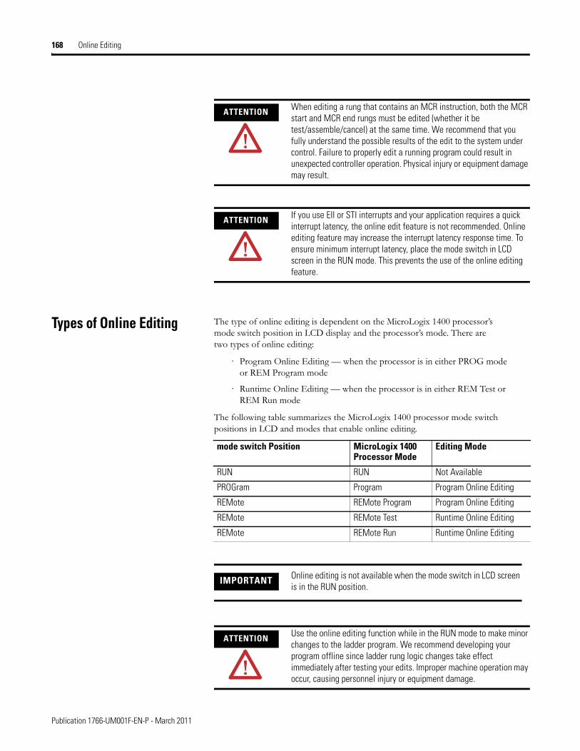
168 Online Editing
Types of Online Editing The type of online editing is dependent on the MicroLogix 1400 processor’s mode switch position in LCD display and the processor’s mode. There are two types of online editing:
· Program Online Editing — when the processor is in either PROG mode or REM Program mode
· Runtime Online Editing — when the processor is in either REM Test or REM Run mode
The following table summarizes the MicroLogix 1400 processor mode switch positions in LCD and modes that enable online editing.
ATTENTION When editing a rung that contains an MCR instruction, both the MCR start and MCR end rungs must be edited (whether it be test/assemble/cancel) at the same time. We recommend that you fully understand the possible results of the edit to the system under control. Failure to properly edit a running program could result in unexpected controller operation. Physical injury or equipment damage may result.
ATTENTION If you use EII or STI interrupts and your application requires a quick interrupt latency, the online edit feature is not recommended. Online editing feature may increase the interrupt latency response time. To ensure minimum interrupt latency, place the mode switch in LCD screen in the RUN mode. This prevents the use of the online editing feature.
mode switch Position MicroLogix 1400Processor Mode
Editing Mode
RUN RUN Not Available
PROGram Program Program Online Editing
REMote REMote Program Program Online Editing
REMote REMote Test Runtime Online Editing
REMote REMote Run Runtime Online Editing
IMPORTANT Online editing is not available when the mode switch in LCD screen is in the RUN position.
ATTENTION Use the online editing function while in the RUN mode to make minor changes to the ladder program. We recommend developing your program offline since ladder rung logic changes take effect immediately after testing your edits. Improper machine operation may occur, causing personnel injury or equipment damage.
Publication 1766-UM001F-EN-P - March 2011
Online Editing 169
Edit Functions in Runtime Online Editing
During a runtime online editing session, the processor is executing ladder logic. The edit zone markers tell the processor that changes exist, but the changes are not executed until you test the edits.
Deleted and replaced (modified) rungs are not removed from the program and inserted rungs are not executed until you assemble or test the edits.
Edit Functions in Program Online Editing
During a program online editing session, the processor is not executing ladder logic. This mode is like the offline editing mode. Note that if a runtime online editing session was performed prior to entering the offline editing mode, edit marked rungs (I, R, and D) appear in the program.
If you perform a program online edit, once you accept or delete the rung, the edits take effect immediately and the power rail is displayed as a solid line. If you edit a rung with edit zone markers, the markers are removed when the rung is accepted.
Publication 1766-UM001F-EN-P - March 2011

170 Online Editing
Notes:
Publication 1766-UM001F-EN-P - March 2011
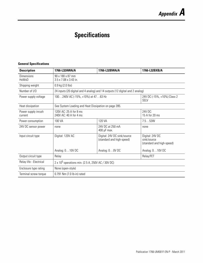
Appendix A
Specifications
General Specifications
Description 1766-L32AWA/A 1766-L32BWA/A 1766-L32BXB/A
DimensionsHxWxD
90 x 180 x 87 mm3.5 x 7.08 x 3.43 in.
Shipping weight 0.9 kg (2.0 lbs)
Number of I/O 24 inputs (20 digital and 4 analog) and 14 outputs (12 digital and 2 analog)
Power supply voltage 100…240V AC (-15%, +10%) at 47…63 Hz 24V DC (-15%, +10%) Class 2 SELV
Heat dissipation See System Loading and Heat Dissipation on page 395.
Power supply inrush current
120V AC: 25 A for 8 ms240V AC: 40 A for 4 ms
24V DC: 15 A for 20 ms
Power consumption 100 VA 120 VA 7.5…53W
24V DC sensor power none 24V DC at 250 mA400 µF max.
none
Input circuit type Digital: 120V AC
Analog: 0…10V DC
Digital: 24V DC sink/source(standard and high-speed)
Analog: 0…0V DC
Digital: 24V DC sink/source(standard and high-speed)
Analog: 0…10V DC
Output circuit type Relay Relay/FET
Relay life - Electrical 2 x 10⁵ operations min. (2.5 A, 250V AC / 30V DC)
Enclosure type rating None (open-style)
Terminal screw torque 0.791 Nm (7.0 lb-in) rated
171 Publication 1766-UM001F-EN-P - March 2011
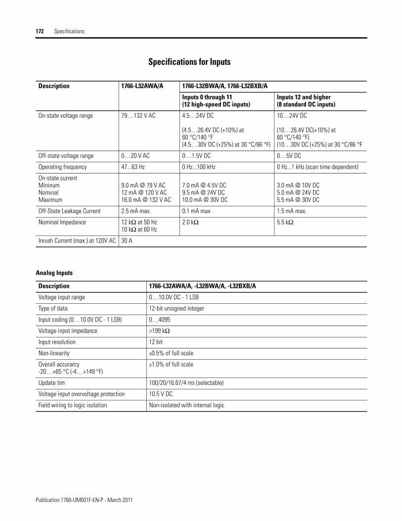
172 Specifications
Specifications for Inputs
Description 1766-L32AWA/A 1766-L32BWA/A, 1766-L32BXB/A
Inputs 0 through 11(12 high-speed DC inputs)
Inputs 12 and higher(8 standard DC inputs)
On-state voltage range 79…132 V AC 4.5…24V DC
(4.5…26.4V DC (+10%) at 60 °C/140 °F(4.5…30V DC (+25%) at 30 °C/86 °F)
10…24V DC
(10…26.4V DC(+10%) at 60 °C/140 °F)(10…30V DC (+25%) at 30 °C/86 °F
Off-state voltage range 0…20 V AC 0…1.5V DC 0…5V DC
Operating frequency 47...63 Hz 0 Hz...100 kHz 0 Hz...1 kHz (scan time dependent)
On-state current MininumNominalMaximum
9.0 mA @ 79 V AC12 mA @ 120 V AC16.0 mA @ 132 V AC
7.0 mA @ 4.5V DC9.5 mA @ 24V DC10.0 mA @ 30V DC
3.0 mA @ 10V DC5.0 mA @ 24V DC5.5 mA @ 30V DC
Off-State Leakage Current 2.5 mA max. 0.1 mA max 1.5 mA max.
Nominal Impedance 12 kΩ at 50 Hz10 kΩ at 60 Hz
2.0 kΩ 5.5 kΩ
Inrush Current (max.) at 120V AC 30 A
Analog Inputs
Description 1766-L32AWA/A, -L32BWA/A, -L32BXB/A
Voltage input range 0…10.0V DC - 1 LSB
Type of data 12-bit unsigned integer
Input coding (0…10.0V DC - 1 LSB) 0…4095
Voltage input impedance >199 kΩ
Input resolution 12 bit
Non-linearity ±0.5% of full scale
Overall accurarcy -20…+65 °C (-4…+149 °F)
±1.0% of full scale
Update tim 100/20/16.67/4 ms (selectable)
Voltage input overvoltage protection 10.5 V DC
Field wiring to logic isolation Non-isolated with internal logic
Publication 1766-UM001F-EN-P - March 2011
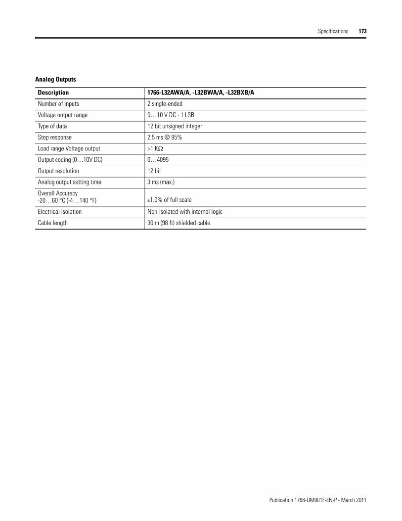
Specifications 173
Analog Outputs
Description 1766-L32AWA/A, -L32BWA/A, -L32BXB/A
Number of inputs 2 single-ended
Voltage output range 0…10 V DC - 1 LSB
Type of data 12 bit unsigned integer
Step response 2.5 ms @ 95%
Load range Voltage output >1 KΩ
Output coding (0…10V DC) 0…4095
Output resolution 12 bit
Analog output setting time 3 ms (max.)
Overall Accuracy -20…60 °C (-4…140 °F) ±1.0% of full scale
Electrical isolation Non-isolated with internal logic
Cable length 30 m (98 ft) shielded cable
Publication 1766-UM001F-EN-P - March 2011
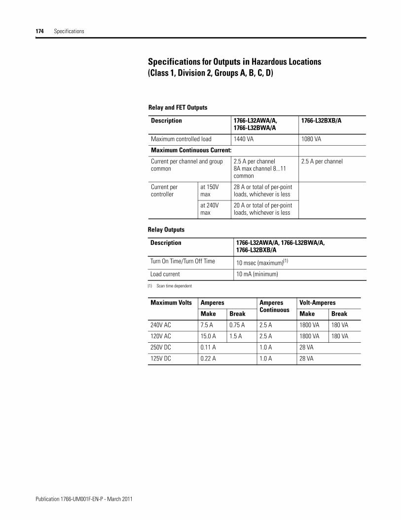
174 Specifications
Specifications for Outputs in Hazardous Locations(Class 1, Division 2, Groups A, B, C, D)
Relay and FET Outputs
Description 1766-L32AWA/A, 1766-L32BWA/A
1766-L32BXB/A
Maximum controlled load 1440 VA 1080 VA
Maximum Continuous Current:
Current per channel and group common
2.5 A per channel8A max channel 8...11 common
2.5 A per channel
Current per controller
at 150V max
28 A or total of per-point loads, whichever is less
at 240V max
20 A or total of per-point loads, whichever is less
Relay Outputs
Description 1766-L32AWA/A, 1766-L32BWA/A, 1766-L32BXB/A
Turn On Time/Turn Off Time 10 msec (maximum)(1)
(1) Scan time dependent
Load current 10 mA (minimum)
Maximum Volts Amperes Amperes Continuous
Volt-Amperes
Make Break Make Break
240V AC 7.5 A 0.75 A 2.5 A 1800 VA 180 VA
120V AC 15.0 A 1.5 A 2.5 A 1800 VA 180 VA
250V DC 0.11 A 1.0 A 28 VA
125V DC 0.22 A 1.0 A 28 VA
Publication 1766-UM001F-EN-P - March 2011
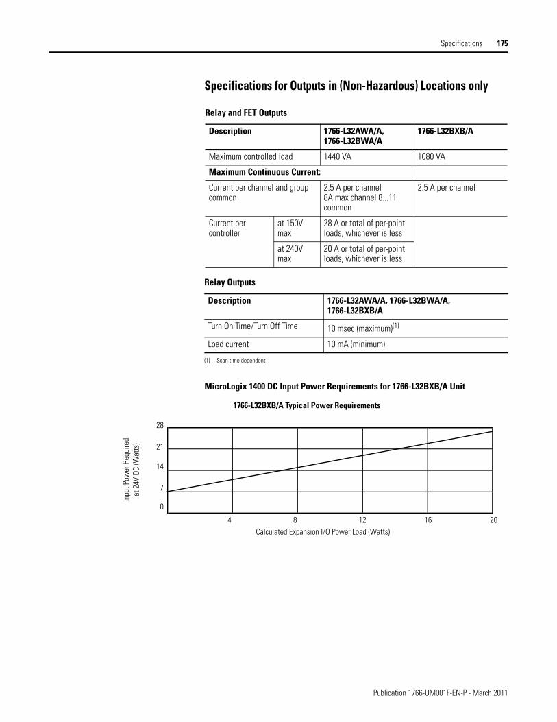
Specifications 175
Specifications for Outputs in (Non-Hazardous) Locations only
MicroLogix 1400 DC Input Power Requirements for 1766-L32BXB/A Unit
Relay and FET Outputs
Description 1766-L32AWA/A, 1766-L32BWA/A
1766-L32BXB/A
Maximum controlled load 1440 VA 1080 VA
Maximum Continuous Current:
Current per channel and group common
2.5 A per channel8A max channel 8...11 common
2.5 A per channel
Current per controller
at 150V max
28 A or total of per-point loads, whichever is less
at 240V max
20 A or total of per-point loads, whichever is less
Relay Outputs
Description 1766-L32AWA/A, 1766-L32BWA/A, 1766-L32BXB/A
Turn On Time/Turn Off Time 10 msec (maximum)(1)
(1) Scan time dependent
Load current 10 mA (minimum)
4 8 12 16 20
28
21
14
7
1766-L32BXB/A Typical Power Requirements
Calculated Expansion I/O Power Load (Watts)
Inpu
t Pow
er R
equi
red
at 2
4V D
C (W
atts
)
0
Publication 1766-UM001F-EN-P - March 2011
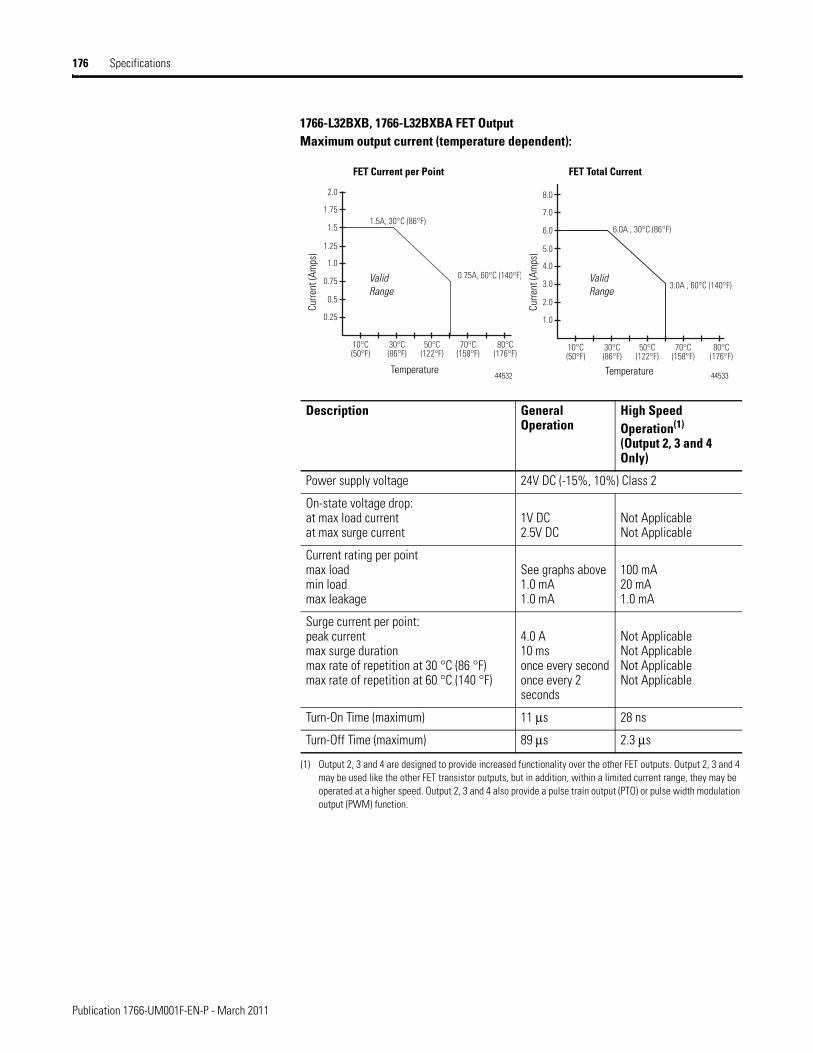
176 Specifications
1766-L32BXB, 1766-L32BXBA FET OutputMaximum output current (temperature dependent):
Description General Operation
High Speed Operation(1)
(Output 2, 3 and 4 Only)
(1) Output 2, 3 and 4 are designed to provide increased functionality over the other FET outputs. Output 2, 3 and 4 may be used like the other FET transistor outputs, but in addition, within a limited current range, they may be operated at a higher speed. Output 2, 3 and 4 also provide a pulse train output (PTO) or pulse width modulation output (PWM) function.
Power supply voltage 24V DC (-15%, 10%) Class 2
On-state voltage drop:at max load currentat max surge current
1V DC2.5V DC
Not ApplicableNot Applicable
Current rating per pointmax loadmin loadmax leakage
See graphs above1.0 mA1.0 mA
100 mA20 mA1.0 mA
Surge current per point:peak currentmax surge durationmax rate of repetition at 30 °C (86 °F)max rate of repetition at 60 °C (140 °F)
4.0 A10 msonce every secondonce every 2 seconds
Not ApplicableNot ApplicableNot ApplicableNot Applicable
Turn-On Time (maximum) 11 μs 28 ns
Turn-Off Time (maximum) 89 μs 2.3 μs
0.25
10°C(50°F)
30°C(86°F)
50°C(122°F)
0.75A, 60°C (140°F)
1.5A, 30°C (86°F)
70°C(158°F)
80°C(176°F)
0.5
0.75
1.0
1.25
1.5
1.75
2.0
1.0
10°C(50°F)
30°C(86°F)
50°C(122°F)
3.0A , 60°C (140°F)
6.0A , 30°C (86°F)
70°C(158°F)
80°C(176°F)
2.0
3.0
4.0
5.0
6.0
7.0
8.0
FET Current per Point FET Total Current
Curre
nt (A
mps
)
Curre
nt (A
mps
)
TemperatureTemperature
Valid Range
Valid Range
44532 44533
Publication 1766-UM001F-EN-P - March 2011
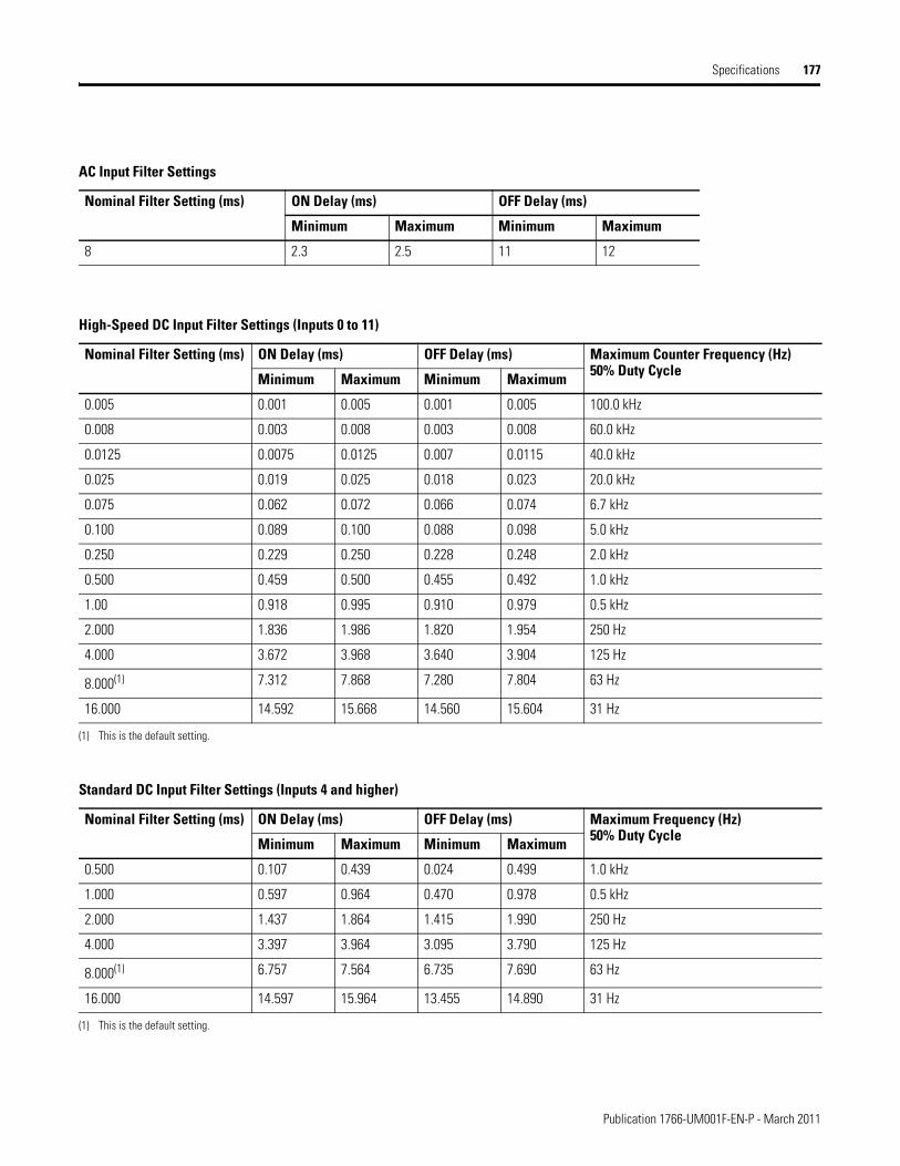
Specifications 177
AC Input Filter Settings
Nominal Filter Setting (ms) ON Delay (ms) OFF Delay (ms)
Minimum Maximum Minimum Maximum
8 2.3 2.5 11 12
High-Speed DC Input Filter Settings (Inputs 0 to 11)
Nominal Filter Setting (ms) ON Delay (ms) OFF Delay (ms) Maximum Counter Frequency (Hz) 50% Duty CycleMinimum Maximum Minimum Maximum
0.005 0.001 0.005 0.001 0.005 100.0 kHz
0.008 0.003 0.008 0.003 0.008 60.0 kHz
0.0125 0.0075 0.0125 0.007 0.0115 40.0 kHz
0.025 0.019 0.025 0.018 0.023 20.0 kHz
0.075 0.062 0.072 0.066 0.074 6.7 kHz
0.100 0.089 0.100 0.088 0.098 5.0 kHz
0.250 0.229 0.250 0.228 0.248 2.0 kHz
0.500 0.459 0.500 0.455 0.492 1.0 kHz
1.00 0.918 0.995 0.910 0.979 0.5 kHz
2.000 1.836 1.986 1.820 1.954 250 Hz
4.000 3.672 3.968 3.640 3.904 125 Hz
8.000(1) 7.312 7.868 7.280 7.804 63 Hz
16.000 14.592 15.668 14.560 15.604 31 Hz
(1) This is the default setting.
Standard DC Input Filter Settings (Inputs 4 and higher)
Nominal Filter Setting (ms) ON Delay (ms) OFF Delay (ms) Maximum Frequency (Hz) 50% Duty CycleMinimum Maximum Minimum Maximum
0.500 0.107 0.439 0.024 0.499 1.0 kHz
1.000 0.597 0.964 0.470 0.978 0.5 kHz
2.000 1.437 1.864 1.415 1.990 250 Hz
4.000 3.397 3.964 3.095 3.790 125 Hz
8.000(1) 6.757 7.564 6.735 7.690 63 Hz
16.000 14.597 15.964 13.455 14.890 31 Hz
(1) This is the default setting.
Publication 1766-UM001F-EN-P - March 2011
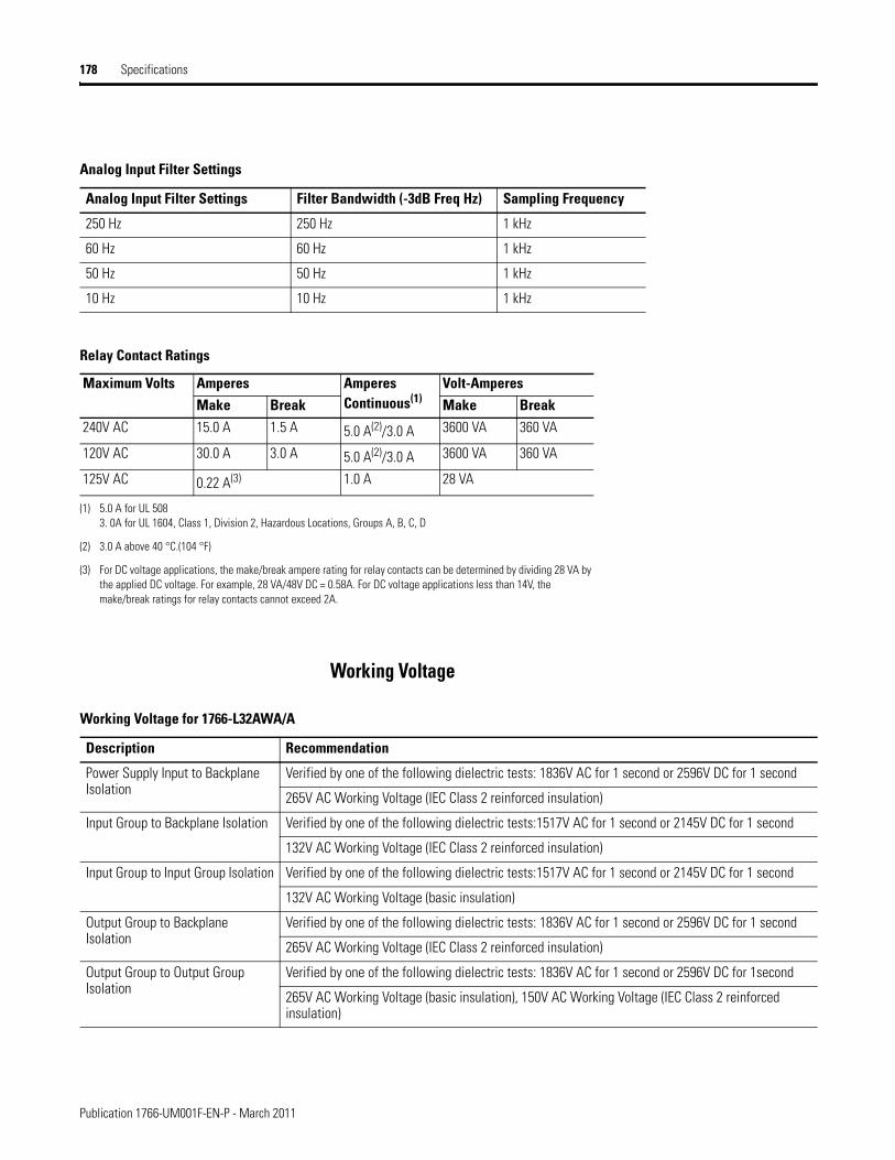
178 Specifications
Working Voltage
Analog Input Filter Settings
Analog Input Filter Settings Filter Bandwidth (-3dB Freq Hz) Sampling Frequency
250 Hz 250 Hz 1 kHz
60 Hz 60 Hz 1 kHz
50 Hz 50 Hz 1 kHz
10 Hz 10 Hz 1 kHz
Relay Contact Ratings
Maximum Volts Amperes Amperes Continuous(1)
Volt-AmperesMake Break Make Break
240V AC 15.0 A 1.5 A 5.0 A(2)/3.0 A 3600 VA 360 VA
120V AC 30.0 A 3.0 A 5.0 A(2)/3.0 A 3600 VA 360 VA
125V AC 0.22 A(3) 1.0 A 28 VA
(1) 5.0 A for UL 5083. 0A for UL 1604, Class 1, Division 2, Hazardous Locations, Groups A, B, C, D
(2) 3.0 A above 40 °C.(104 °F)
(3) For DC voltage applications, the make/break ampere rating for relay contacts can be determined by dividing 28 VA by the applied DC voltage. For example, 28 VA/48V DC = 0.58A. For DC voltage applications less than 14V, the make/break ratings for relay contacts cannot exceed 2A.
Working Voltage for 1766-L32AWA/A
Description Recommendation
Power Supply Input to Backplane Isolation
Verified by one of the following dielectric tests: 1836V AC for 1 second or 2596V DC for 1 second
265V AC Working Voltage (IEC Class 2 reinforced insulation)
Input Group to Backplane Isolation Verified by one of the following dielectric tests:1517V AC for 1 second or 2145V DC for 1 second
132V AC Working Voltage (IEC Class 2 reinforced insulation)
Input Group to Input Group Isolation Verified by one of the following dielectric tests:1517V AC for 1 second or 2145V DC for 1 second
132V AC Working Voltage (basic insulation)
Output Group to Backplane Isolation
Verified by one of the following dielectric tests: 1836V AC for 1 second or 2596V DC for 1 second
265V AC Working Voltage (IEC Class 2 reinforced insulation)
Output Group to Output Group Isolation
Verified by one of the following dielectric tests: 1836V AC for 1 second or 2596V DC for 1second
265V AC Working Voltage (basic insulation), 150V AC Working Voltage (IEC Class 2 reinforced insulation)
Publication 1766-UM001F-EN-P - March 2011
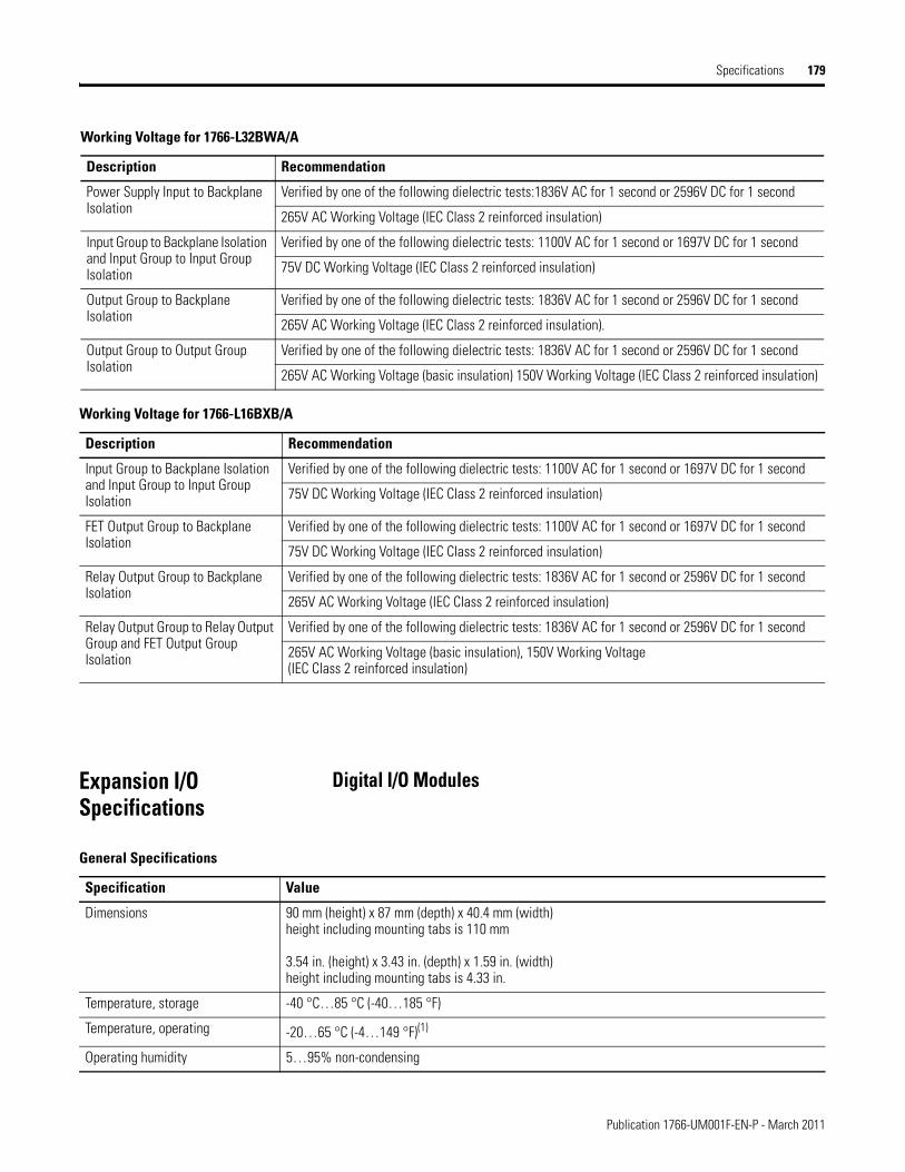
Specifications 179
Expansion I/O Specifications
Digital I/O Modules
Working Voltage for 1766-L32BWA/A
Description Recommendation
Power Supply Input to Backplane Isolation
Verified by one of the following dielectric tests:1836V AC for 1 second or 2596V DC for 1 second
265V AC Working Voltage (IEC Class 2 reinforced insulation)
Input Group to Backplane Isolation and Input Group to Input Group Isolation
Verified by one of the following dielectric tests: 1100V AC for 1 second or 1697V DC for 1 second
75V DC Working Voltage (IEC Class 2 reinforced insulation)
Output Group to Backplane Isolation
Verified by one of the following dielectric tests: 1836V AC for 1 second or 2596V DC for 1 second
265V AC Working Voltage (IEC Class 2 reinforced insulation).
Output Group to Output Group Isolation
Verified by one of the following dielectric tests: 1836V AC for 1 second or 2596V DC for 1 second
265V AC Working Voltage (basic insulation) 150V Working Voltage (IEC Class 2 reinforced insulation)
Working Voltage for 1766-L16BXB/A
Description Recommendation
Input Group to Backplane Isolation and Input Group to Input Group Isolation
Verified by one of the following dielectric tests: 1100V AC for 1 second or 1697V DC for 1 second
75V DC Working Voltage (IEC Class 2 reinforced insulation)
FET Output Group to Backplane Isolation
Verified by one of the following dielectric tests: 1100V AC for 1 second or 1697V DC for 1 second
75V DC Working Voltage (IEC Class 2 reinforced insulation)
Relay Output Group to Backplane Isolation
Verified by one of the following dielectric tests: 1836V AC for 1 second or 2596V DC for 1 second
265V AC Working Voltage (IEC Class 2 reinforced insulation)
Relay Output Group to Relay Output Group and FET Output Group Isolation
Verified by one of the following dielectric tests: 1836V AC for 1 second or 2596V DC for 1 second
265V AC Working Voltage (basic insulation), 150V Working Voltage (IEC Class 2 reinforced insulation)
General Specifications
Specification Value
Dimensions 90 mm (height) x 87 mm (depth) x 40.4 mm (width)height including mounting tabs is 110 mm
3.54 in. (height) x 3.43 in. (depth) x 1.59 in. (width)height including mounting tabs is 4.33 in.
Temperature, storage -40 °C…85 °C (-40…185 °F)
Temperature, operating -20…65 °C (-4…149 °F)(1)
Operating humidity 5…95% non-condensing
Publication 1766-UM001F-EN-P - March 2011
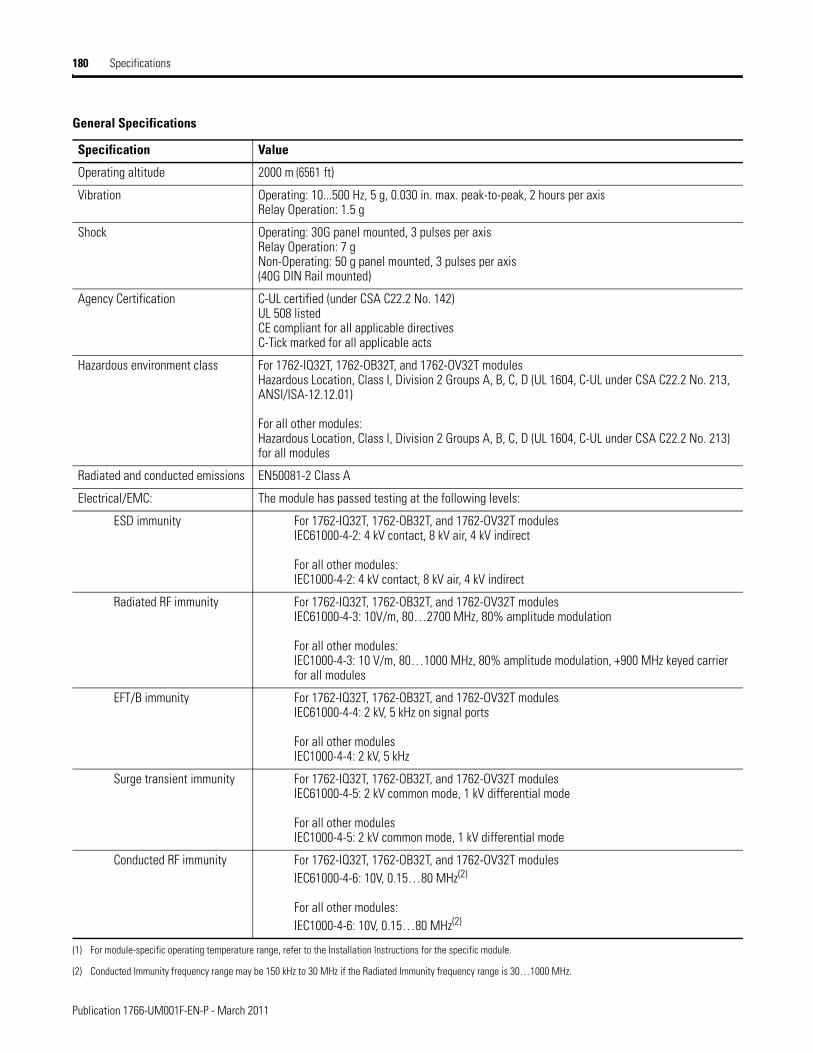
180 Specifications
Operating altitude 2000 m (6561 ft)
Vibration Operating: 10...500 Hz, 5 g, 0.030 in. max. peak-to-peak, 2 hours per axisRelay Operation: 1.5 g
Shock Operating: 30G panel mounted, 3 pulses per axisRelay Operation: 7 gNon-Operating: 50 g panel mounted, 3 pulses per axis(40G DIN Rail mounted)
Agency Certification C-UL certified (under CSA C22.2 No. 142)UL 508 listedCE compliant for all applicable directivesC-Tick marked for all applicable acts
Hazardous environment class For 1762-IQ32T, 1762-OB32T, and 1762-OV32T modulesHazardous Location, Class I, Division 2 Groups A, B, C, D (UL 1604, C-UL under CSA C22.2 No. 213, ANSI/ISA-12.12.01)
For all other modules:Hazardous Location, Class I, Division 2 Groups A, B, C, D (UL 1604, C-UL under CSA C22.2 No. 213) for all modules
Radiated and conducted emissions EN50081-2 Class A
Electrical/EMC: The module has passed testing at the following levels:
ESD immunity For 1762-IQ32T, 1762-OB32T, and 1762-OV32T modulesIEC61000-4-2: 4 kV contact, 8 kV air, 4 kV indirect
For all other modules:IEC1000-4-2: 4 kV contact, 8 kV air, 4 kV indirect
Radiated RF immunity For 1762-IQ32T, 1762-OB32T, and 1762-OV32T modulesIEC61000-4-3: 10V/m, 80…2700 MHz, 80% amplitude modulation
For all other modules:IEC1000-4-3: 10 V/m, 80…1000 MHz, 80% amplitude modulation, +900 MHz keyed carrier for all modules
EFT/B immunity For 1762-IQ32T, 1762-OB32T, and 1762-OV32T modulesIEC61000-4-4: 2 kV, 5 kHz on signal ports
For all other modulesIEC1000-4-4: 2 kV, 5 kHz
Surge transient immunity For 1762-IQ32T, 1762-OB32T, and 1762-OV32T modulesIEC61000-4-5: 2 kV common mode, 1 kV differential mode
For all other modulesIEC1000-4-5: 2 kV common mode, 1 kV differential mode
Conducted RF immunity For 1762-IQ32T, 1762-OB32T, and 1762-OV32T modulesIEC61000-4-6: 10V, 0.15…80 MHz(2)
For all other modules:IEC1000-4-6: 10V, 0.15…80 MHz(2)
(1) For module-specific operating temperature range, refer to the Installation Instructions for the specific module.
(2) Conducted Immunity frequency range may be 150 kHz to 30 MHz if the Radiated Immunity frequency range is 30…1000 MHz.
General Specifications
Specification Value
Publication 1766-UM001F-EN-P - March 2011
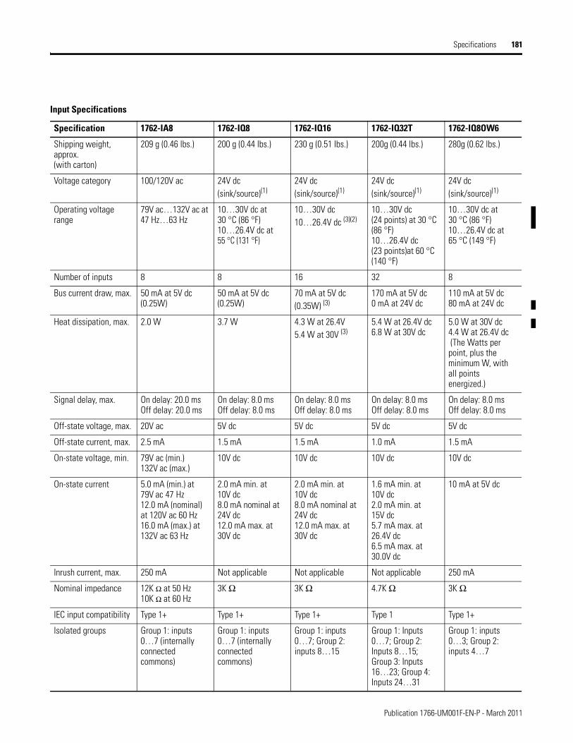
Specifications 181
Input Specifications
Specification 1762-IA8 1762-IQ8 1762-IQ16 1762-IQ32T 1762-IQ8OW6
Shipping weight, approx.(with carton)
209 g (0.46 lbs.) 200 g (0.44 lbs.) 230 g (0.51 lbs.) 200g (0.44 lbs.) 280g (0.62 lbs.)
Voltage category 100/120V ac 24V dc (sink/source)(1)
24V dc (sink/source)(1)
24V dc(sink/source)(1)
24V dc (sink/source)(1)
Operating voltage range
79V ac…132V ac at 47 Hz…63 Hz
10…30V dc at 30 °C (86 °F)10…26.4V dc at 55 °C (131 °F)
10…30V dc 10…26.4V dc (3)(2)
10…30V dc (24 points) at 30 °C (86 °F)10…26.4V dc (23 points)at 60 °C (140 °F)
10…30V dc at 30 °C (86 °F)10…26.4V dc at 65 °C (149 °F)
Number of inputs 8 8 16 32 8
Bus current draw, max. 50 mA at 5V dc (0.25W)
50 mA at 5V dc (0.25W)
70 mA at 5V dc (0.35W) (3)
170 mA at 5V dc0 mA at 24V dc
110 mA at 5V dc80 mA at 24V dc
Heat dissipation, max. 2.0 W 3.7 W 4.3 W at 26.4V5.4 W at 30V (3)
5.4 W at 26.4V dc6.8 W at 30V dc
5.0 W at 30V dc4.4 W at 26.4V dc (The Watts per point, plus the minimum W, with all points energized.)
Signal delay, max. On delay: 20.0 msOff delay: 20.0 ms
On delay: 8.0 msOff delay: 8.0 ms
On delay: 8.0 msOff delay: 8.0 ms
On delay: 8.0 msOff delay: 8.0 ms
On delay: 8.0 msOff delay: 8.0 ms
Off-state voltage, max. 20V ac 5V dc 5V dc 5V dc 5V dc
Off-state current, max. 2.5 mA 1.5 mA 1.5 mA 1.0 mA 1.5 mA
On-state voltage, min. 79V ac (min.) 132V ac (max.)
10V dc 10V dc 10V dc 10V dc
On-state current 5.0 mA (min.) at 79V ac 47 Hz12.0 mA (nominal) at 120V ac 60 Hz16.0 mA (max.) at 132V ac 63 Hz
2.0 mA min. at 10V dc8.0 mA nominal at 24V dc12.0 mA max. at 30V dc
2.0 mA min. at 10V dc8.0 mA nominal at 24V dc12.0 mA max. at 30V dc
1.6 mA min. at 10V dc2.0 mA min. at 15V dc5.7 mA max. at 26.4V dc6.5 mA max. at 30.0V dc
10 mA at 5V dc
Inrush current, max. 250 mA Not applicable Not applicable Not applicable 250 mA
Nominal impedance 12K Ω at 50 Hz10K Ω at 60 Hz
3K Ω 3K Ω 4.7K Ω 3K Ω
IEC input compatibility Type 1+ Type 1+ Type 1+ Type 1 Type 1+
Isolated groups Group 1: inputs 0…7 (internally connected commons)
Group 1: inputs 0…7 (internally connected commons)
Group 1: inputs 0…7; Group 2: inputs 8…15
Group 1: Inputs 0…7; Group 2: Inputs 8…15; Group 3: Inputs 16…23; Group 4: Inputs 24…31
Group 1: inputs 0…3; Group 2: inputs 4…7
Publication 1766-UM001F-EN-P - March 2011
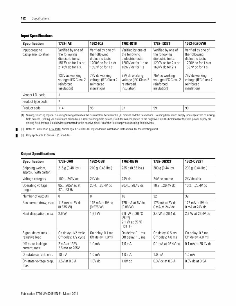
182 Specifications
Input group to backplane isolation
Verified by one of the following dielectric tests: 1517V ac for 1 s or 2145V dc for 1 s.
132V ac working voltage (IEC Class 2 reinforced insulation)
Verified by one of the following dielectric tests: 1200V ac for 1 s or 1697V dc for 1 s
75V dc working voltage (IEC Class 2 reinforced insulation)
Verified by one of the following dielectric tests: 1200V ac for 1 s or 1697V dc for 1 s
75V dc working voltage (IEC Class 2 reinforced insulation)
Verified by one of the following dielectric tests: 1200V ac for 2 s or 1697V dc for 2 s
75V dc working voltage (IEC Class 2 reinforced insulation)
Verified by one of the following dielectric tests: 1200V ac for 1 s or 1697V dc for 1 s
75V dc working voltage (IEC Class 2 reinforced insulation)
Vendor I.D. code 1
Product type code 7
Product code 114 96 97 99 98
(1) Sinking/Sourcing Inputs - Sourcing/sinking describes the current flow between the I/O module and the field device. Sourcing I/O circuits supply (source) current to sinking field devices. Sinking I/O circuits are driven by a current sourcing field device. Field devices connected to the negative side (DC Common) of the field power supply are sinking field devices. Field devices connected to the positive side (+V) of the field supply are sourcing field devices.
(2) Refer to Publication 1762-IN10, MicroLogix 1762-IQ16 DC Input Module Installation Instructions, for the derating chart.
(3) Only applicable to Series B I/O modules.
Input Specifications
Specification 1762-IA8 1762-IQ8 1762-IQ16 1762-IQ32T 1762-IQ8OW6
Output Specifications
Specification 1762-OA8 1762-OB8 1762-OB16 1762-OB32T 1762-OV32T
Shipping weight, approx. (with carton)
215 g (0.48 lbs.) 210 g (0.46 lbs.) 235 g (0.52 lbs.) 200 g (0.44 lbs.) 200 g (0.44 lbs.)
Voltage category 100…240V ac 24V dc 24V dc 24V dc source 24V dc sink
Operating voltage range
85…265V ac at 47…63 Hz
20.4…26.4V dc 20.4…26.4V dc 10.2…26.4V dc 10.2…26.4V dc
Number of outputs 8 8 16 32 32
Bus current draw, max. 115 mA at 5V dc (0.575 W)
115 mA at 5V dc (0.575 W)
175 mA at 5V dc (0.88 W)
175 mA at 5V dc0 mA at 24V dc
175 mA at 5V dc0 mA at 24V dc
Heat dissipation, max. 2.9 W 1.61 W 2.9 W at 30 °C (86 °F)2.1 W at 55 °C (131 °F)
3.4 W at 26.4 dc 2.7 W at 26.4V dc
Signal delay, max. – resistive load
On delay: 1/2 cycleOff delay: 1/2 cycle
On delay: 0.1 msOff delay: 1.0ms
On delay: 0.1 msOff delay: 1.0 ms
On delay: 0.5 msOff delay: 4.0 ms
On delay: 0.5 msOff delay: 4.0 ms
Off-state leakage current, max.
2 mA at 132V, 2.5 mA at 265V
1.0 mA 1.0 mA 0.1 mA at 26.4V dc 0.1 mA at 26.4V dc
On-state current, min. 10 mA 1.0 mA 1.0 mA 1.0 mA 1.0 mA
On-state voltage drop, max.
1.5V at 0.5 A 1.0V dc 1.0V dc 0.3V dc at 0.5 A 0.3V dc at 0.5A
Publication 1766-UM001F-EN-P - March 2011
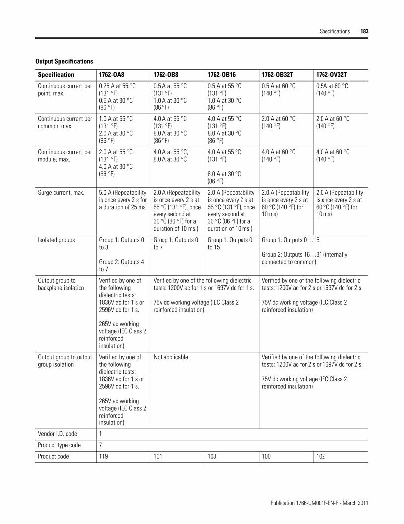
Specifications 183
Continuous current per point, max.
0.25 A at 55 °C (131 °F)0.5 A at 30 °C (86 °F)
0.5 A at 55 °C (131 °F)1.0 A at 30 °C (86 °F)
0.5 A at 55 °C (131 °F)1.0 A at 30 °C (86 °F)
0.5 A at 60 °C (140 °F)
0.5A at 60 °C (140 °F)
Continuous current per common, max.
1.0 A at 55 °C (131 °F)2.0 A at 30 °C (86 °F)
4.0 A at 55 °C (131 °F)8.0 A at 30 °C (86 °F)
4.0 A at 55 °C (131 °F)8.0 A at 30 °C (86 °F)
2.0 A at 60 °C (140 °F)
2.0 A at 60 °C (140 °F)
Continuous current per module, max.
2.0 A at 55 °C (131 °F)4.0 A at 30 °C (86 °F)
4.0 A at 55 °C; 8.0 A at 30 °C
4.0 A at 55 °C (131 °F)
8.0 A at 30 °C (86 °F)
4.0 A at 60 °C (140 °F)
4.0 A at 60 °C (140 °F)
Surge current, max. 5.0 A (Repeatability is once every 2 s for a duration of 25 ms.
2.0 A (Repeatability is once every 2 s at 55 °C (131 °F), once every second at 30 °C (86 °F) for a duration of 10 ms.)
2.0 A (Repeatability is once every 2 s at 55 °C (131 °F), once every second at 30 °C (86 °F) for a duration of 10 ms.)
2.0 A (Repeatability is once every 2 s at 60 °C (140 °F) for 10 ms)
2.0 A (Repeatability is once every 2 s at 60 °C (140 °F) for 10 ms)
Isolated groups Group 1: Outputs 0 to 3
Group 2: Outputs 4 to 7
Group 1: Outputs 0 to 7
Group 1: Outputs 0 to 15
Group 1: Outputs 0…15
Group 2: Outputs 16…31 (internally connected to common)
Output group to backplane isolation
Verified by one of the following dielectric tests: 1836V ac for 1 s or 2596V dc for 1 s.
265V ac working voltage (IEC Class 2 reinforced insulation)
Verified by one of the following dielectric tests: 1200V ac for 1 s or 1697V dc for 1 s.
75V dc working voltage (IEC Class 2 reinforced insulation)
Verified by one of the following dielectric tests: 1200V ac for 2 s or 1697V dc for 2 s.
75V dc working voltage (IEC Class 2 reinforced insulation)
Output group to output group isolation
Verified by one of the following dielectric tests: 1836V ac for 1 s or 2596V dc for 1 s.
265V ac working voltage (IEC Class 2 reinforced insulation)
Not applicable Verified by one of the following dielectric tests: 1200V ac for 2 s or 1697V dc for 2 s.
75V dc working voltage (IEC Class 2 reinforced insulation)
Vendor I.D. code 1
Product type code 7
Product code 119 101 103 100 102
Output Specifications
Specification 1762-OA8 1762-OB8 1762-OB16 1762-OB32T 1762-OV32T
Publication 1766-UM001F-EN-P - March 2011
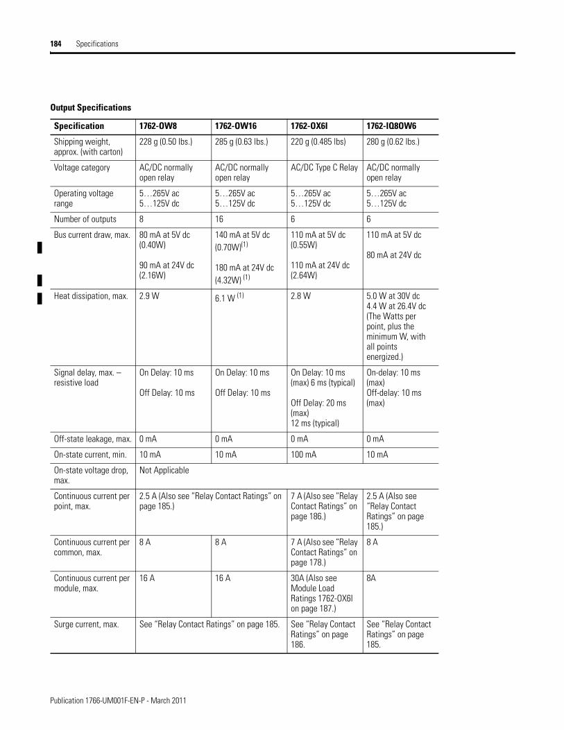
184 Specifications
Output Specifications
Specification 1762-OW8 1762-OW16 1762-OX6I 1762-IQ8OW6
Shipping weight, approx. (with carton)
228 g (0.50 lbs.) 285 g (0.63 lbs.) 220 g (0.485 lbs) 280 g (0.62 lbs.)
Voltage category AC/DC normally open relay
AC/DC normally open relay
AC/DC Type C Relay AC/DC normally open relay
Operating voltage range
5…265V ac5…125V dc
5…265V ac5…125V dc
5…265V ac5…125V dc
5…265V ac5…125V dc
Number of outputs 8 16 6 6
Bus current draw, max. 80 mA at 5V dc (0.40W)
90 mA at 24V dc (2.16W)
140 mA at 5V dc (0.70W)(1)
180 mA at 24V dc (4.32W) (1)
110 mA at 5V dc (0.55W)
110 mA at 24V dc (2.64W)
110 mA at 5V dc
80 mA at 24V dc
Heat dissipation, max. 2.9 W 6.1 W (1) 2.8 W 5.0 W at 30V dc4.4 W at 26.4V dc (The Watts per point, plus the minimum W, with all points energized.)
Signal delay, max. – resistive load
On Delay: 10 ms
Off Delay: 10 ms
On Delay: 10 ms
Off Delay: 10 ms
On Delay: 10 ms (max) 6 ms (typical)
Off Delay: 20 ms (max) 12 ms (typical)
On-delay: 10 ms (max) Off-delay: 10 ms (max)
Off-state leakage, max. 0 mA 0 mA 0 mA 0 mA
On-state current, min. 10 mA 10 mA 100 mA 10 mA
On-state voltage drop, max.
Not Applicable
Continuous current per point, max.
2.5 A (Also see “Relay Contact Ratings” on page 185.)
7 A (Also see “Relay Contact Ratings” on page 186.)
2.5 A (Also see “Relay Contact Ratings” on page 185.)
Continuous current per common, max.
8 A 8 A 7 A (Also see “Relay Contact Ratings” on page 178.)
8 A
Continuous current per module, max.
16 A 16 A 30A (Also see Module Load Ratings 1762-OX6I on page 187.)
8A
Surge current, max. See “Relay Contact Ratings” on page 185. See “Relay Contact Ratings” on page 186.
See “Relay Contact Ratings” on page 185.
Publication 1766-UM001F-EN-P - March 2011
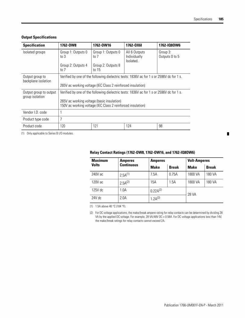
Specifications 185
Isolated groups Group 1: Outputs 0 to 3
Group 2: Outputs 4 to 7
Group 1: Outputs 0 to 7
Group 2: Outputs 8 to 15
All 6 Outputs Individually Isolated.
Group 3:Outputs 0 to 5
Output group to backplane isolation
Verified by one of the following dielectric tests: 1836V ac for 1 s or 2596V dc for 1 s.
265V ac working voltage (IEC Class 2 reinforced insulation)
Output group to output group isolation
Verified by one of the following dielectric tests: 1836V ac for 1 s or 2596V dc for 1 s.
265V ac working voltage (basic insulation)150V ac working voltage (IEC Class 2 reinforced insulation)
Vendor I.D. code 1
Product type code 7
Product code 120 121 124 98
(1) Only applicable to Series B I/O modules.
Output Specifications
Specification 1762-OW8 1762-OW16 1762-OX6I 1762-IQ8OW6
Relay Contact Ratings (1762-OW8, 1762-OW16, and 1762-IQ8OW6)
Maximum Volts
Amperes Continuous
Amperes Volt-Amperes
Make Break Make Break
240V ac 2.5A(1)
(1) 1.5A above 40 °C (104 °F).
7.5A 0.75A 1800 VA 180 VA
120V ac 2.5A(2) 15A 1.5A 1800 VA 180 VA
125V dc 1.0A 0.22A(2)
(2) For DC voltage applications, the make/break ampere rating for relay contacts can be determined by dividing 28 VA by the applied DC voltage. For example, 28 VA/48V DC = 0.58A. For DC voltage applications less than 14V, the make/break ratings for relay contacts cannot exceed 2A.
28 VA24V dc 2.0A 1.2A(3)
Publication 1766-UM001F-EN-P - March 2011
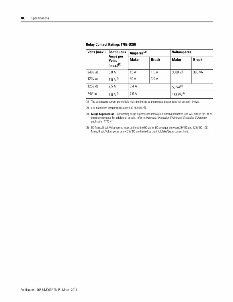
186 Specifications
Relay Contact Ratings 1762-OX6I
Volts (max.) Continuous Amps per Point (max.)(1)
(1) The continuous current per module must be limited so the module power does not exceed 1440VA.
Amperes(3)
(3) Surge Suppression – Connecting surge suppressors across your external inductive load will extend the life of the relay contacts. For additional details, refer to Industrial Automation Wiring and Grounding Guidelines, publication 1770-4.1.
Voltamperes
Make Break Make Break
240V ac 5.0 A 15 A 1.5 A 3600 VA 360 VA
120V ac 7.0 A(2)
(2) 6 A in ambient temperatures above 40 °C (104.°F)
30 A 3.0 A
125V dc 2.5 A 0.4 A 50 VA(4)
(4) DC Make/Break Voltamperes must be limited to 50 VA for DC voltages between 28V DC and 125V DC. DC Make/Break Voltamperes below 28V DC are limited by the 7 A Make/Break current limit.
24V dc 7.0 A(2) 7.0 A 168 VA(4)
Publication 1766-UM001F-EN-P - March 2011
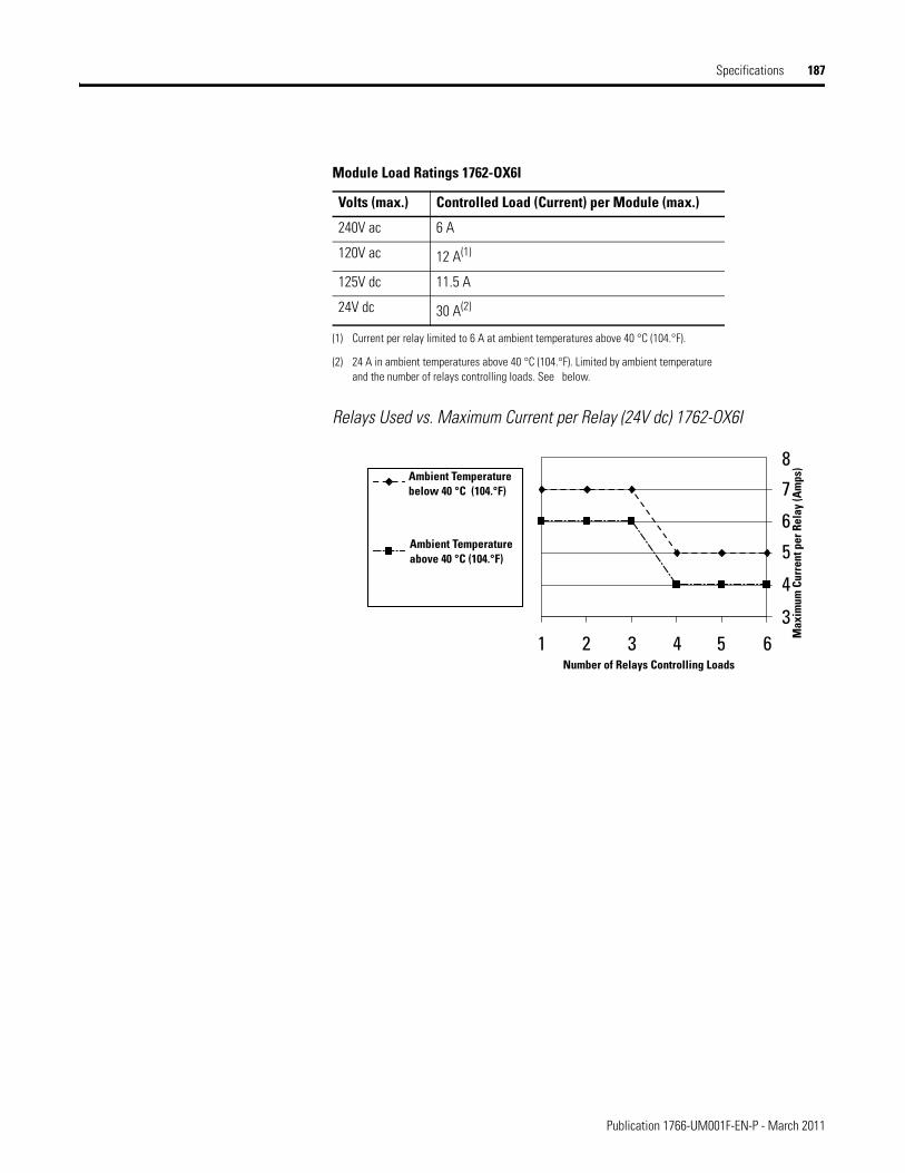
Specifications 187
Relays Used vs. Maximum Current per Relay (24V dc) 1762-OX6I
Module Load Ratings 1762-OX6I
Volts (max.) Controlled Load (Current) per Module (max.)
240V ac 6 A
120V ac 12 A(1)
(1) Current per relay limited to 6 A at ambient temperatures above 40 °C (104.°F).
125V dc 11.5 A
24V dc 30 A(2)
(2) 24 A in ambient temperatures above 40 °C (104.°F). Limited by ambient temperature and the number of relays controlling loads. See below.
1 2 33
4
5
6
7
8
4 5 6Number of Relays Controlling Loads
Max
imum
Cur
rent
per
Rel
ay (A
mps
)
Ambient Temperaturebelow 40 °C (104.°F)
Ambient Temperatureabove 40 °C (104.°F)
Publication 1766-UM001F-EN-P - March 2011
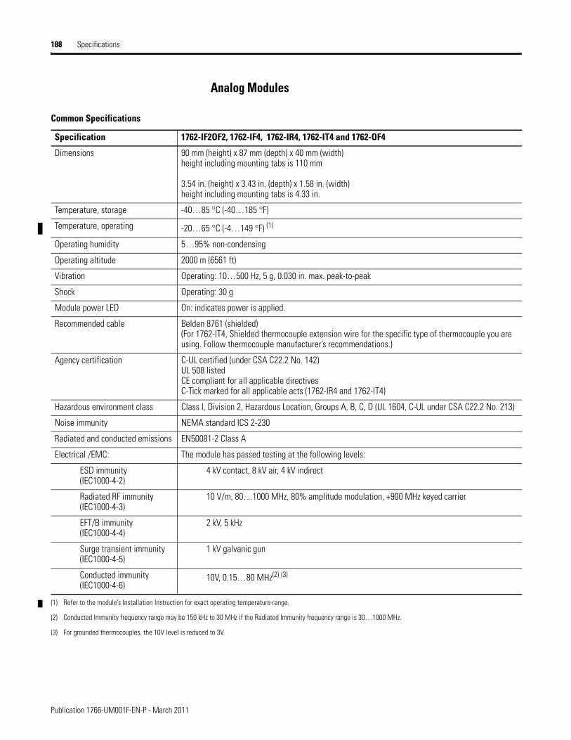
188 Specifications
Analog Modules
Common Specifications
Specification 1762-IF2OF2, 1762-IF4, 1762-IR4, 1762-IT4 and 1762-OF4
Dimensions 90 mm (height) x 87 mm (depth) x 40 mm (width)height including mounting tabs is 110 mm
3.54 in. (height) x 3.43 in. (depth) x 1.58 in. (width)height including mounting tabs is 4.33 in.
Temperature, storage -40…85 °C (-40…185 °F)
Temperature, operating -20…65 °C (-4…149 °F) (1)
Operating humidity 5…95% non-condensing
Operating altitude 2000 m (6561 ft)
Vibration Operating: 10…500 Hz, 5 g, 0.030 in. max. peak-to-peak
Shock Operating: 30 g
Module power LED On: indicates power is applied.
Recommended cable Belden 8761 (shielded)(For 1762-IT4, Shielded thermocouple extension wire for the specific type of thermocouple you are using. Follow thermocouple manufacturer’s recommendations.)
Agency certification C-UL certified (under CSA C22.2 No. 142)UL 508 listedCE compliant for all applicable directivesC-Tick marked for all applicable acts (1762-IR4 and 1762-IT4)
Hazardous environment class Class I, Division 2, Hazardous Location, Groups A, B, C, D (UL 1604, C-UL under CSA C22.2 No. 213)
Noise immunity NEMA standard ICS 2-230
Radiated and conducted emissions EN50081-2 Class A
Electrical /EMC: The module has passed testing at the following levels:
ESD immunity(IEC1000-4-2)
4 kV contact, 8 kV air, 4 kV indirect
Radiated RF immunity(IEC1000-4-3)
10 V/m, 80…1000 MHz, 80% amplitude modulation, +900 MHz keyed carrier
EFT/B immunity(IEC1000-4-4)
2 kV, 5 kHz
Surge transient immunity(IEC1000-4-5)
1 kV galvanic gun
Conducted immunity(IEC1000-4-6)
10V, 0.15…80 MHz(2) (3)
(1) Refer to the module’s Installation Instruction for exact operating temperature range.
(2) Conducted Immunity frequency range may be 150 kHz to 30 MHz if the Radiated Immunity frequency range is 30…1000 MHz.
(3) For grounded thermocouples, the 10V level is reduced to 3V.
Publication 1766-UM001F-EN-P - March 2011
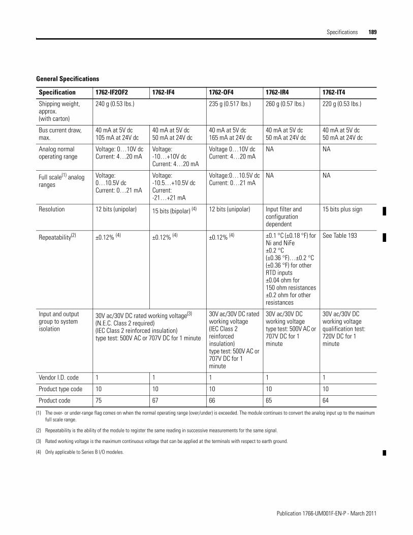
Specifications 189
General Specifications
Specification 1762-IF2OF2 1762-IF4 1762-OF4 1762-IR4 1762-IT4
Shipping weight, approx.(with carton)
240 g (0.53 lbs.) 235 g (0.517 lbs.) 260 g (0.57 lbs.) 220 g (0.53 lbs.)
Bus current draw, max.
40 mA at 5V dc105 mA at 24V dc
40 mA at 5V dc50 mA at 24V dc
40 mA at 5V dc165 mA at 24V dc
40 mA at 5V dc50 mA at 24V dc
40 mA at 5V dc50 mA at 24V dc
Analog normal operating range
Voltage: 0…10V dcCurrent: 4…20 mA
Voltage: -10…+10V dcCurrent: 4…20 mA
Voltage 0…10V dcCurrent: 4…20 mA
NA NA
Full scale(1) analog ranges
Voltage: 0…10.5V dcCurrent: 0…21 mA
Voltage: -10.5…+10.5V dcCurrent: -21…+21 mA
Voltage:0…10.5V dcCurrent: 0…21 mA
NA NA
Resolution 12 bits (unipolar) 15 bits (bipolar) (4) 12 bits (unipolar) Input filter and configuration dependent
15 bits plus sign
Repeatability(2) ±0.12% (4) ±0.12% (4) ±0.12% (4) ±0.1 °C (±0.18 °F) for Ni and NiFe±0.2 °C (±0.36 °F)…±0.2 °C (±0.36 °F) for other RTD inputs±0.04 ohm for 150 ohm resistances±0.2 ohm for other resistances
See Table 193
Input and output group to system isolation
30V ac/30V DC rated working voltage(3)
(N.E.C. Class 2 required) (IEC Class 2 reinforced insulation) type test: 500V AC or 707V DC for 1 minute
30V ac/30V DC rated working voltage(IEC Class 2 reinforced insulation) type test: 500V AC or 707V DC for 1 minute
30V ac/30V DC working voltagetype test: 500V AC or 707V DC for 1 minute
30V ac/30V DC working voltagequalification test: 720V DC for 1 minute
Vendor I.D. code 1 1 1 1 1
Product type code 10 10 10 10 10
Product code 75 67 66 65 64
(1) The over- or under-range flag comes on when the normal operating range (over/under) is exceeded. The module continues to convert the analog input up to the maximum full scale range.
(2) Repeatability is the ability of the module to register the same reading in successive measurements for the same signal.
(3) Rated working voltage is the maximum continuous voltage that can be applied at the terminals with respect to earth ground.
(4) Only applicable to Series B I/O modeles.
Publication 1766-UM001F-EN-P - March 2011
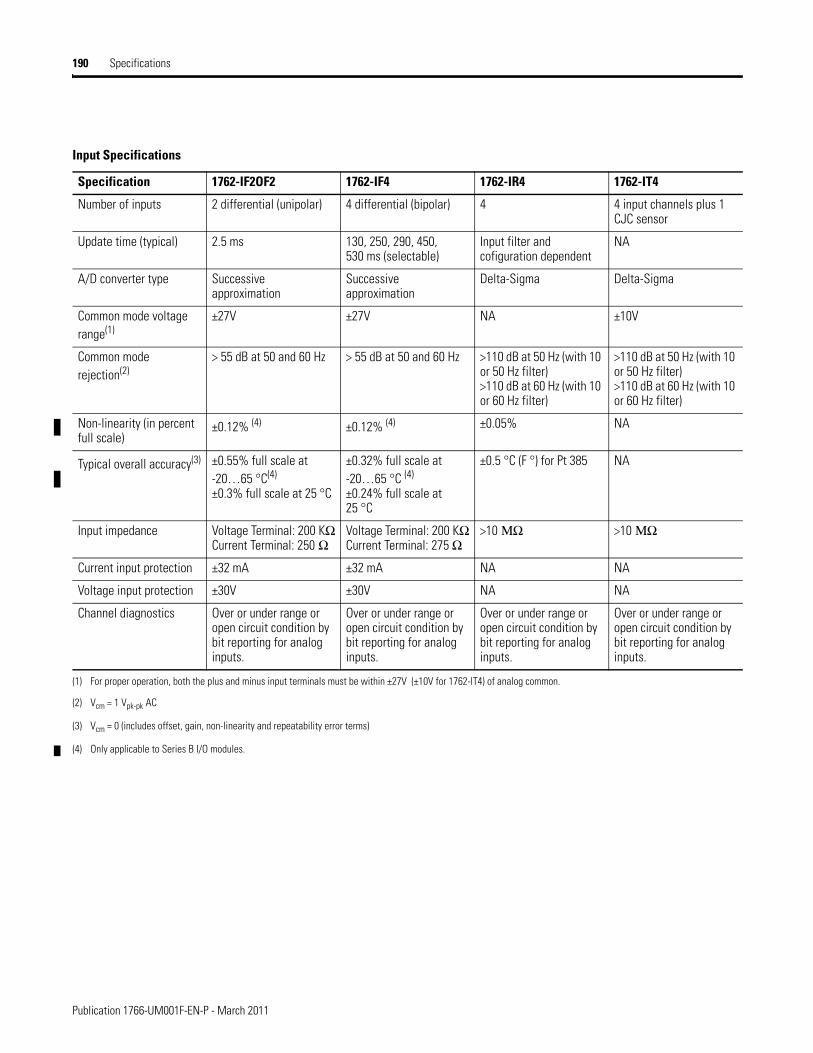
190 Specifications
Input Specifications
Specification 1762-IF2OF2 1762-IF4 1762-IR4 1762-IT4
Number of inputs 2 differential (unipolar) 4 differential (bipolar) 4 4 input channels plus 1 CJC sensor
Update time (typical) 2.5 ms 130, 250, 290, 450, 530 ms (selectable)
Input filter and cofiguration dependent
NA
A/D converter type Successive approximation
Successive approximation
Delta-Sigma Delta-Sigma
Common mode voltage range(1)
±27V ±27V NA ±10V
Common mode rejection(2)
> 55 dB at 50 and 60 Hz > 55 dB at 50 and 60 Hz >110 dB at 50 Hz (with 10 or 50 Hz filter)>110 dB at 60 Hz (with 10 or 60 Hz filter)
>110 dB at 50 Hz (with 10 or 50 Hz filter)>110 dB at 60 Hz (with 10 or 60 Hz filter)
Non-linearity (in percent full scale)
±0.12% (4) ±0.12% (4) ±0.05% NA
Typical overall accuracy(3) ±0.55% full scale at -20…65 °C(4)
±0.3% full scale at 25 °C
±0.32% full scale at -20…65 °C (4) ±0.24% full scale at 25 °C
±0.5 °C (F °) for Pt 385 NA
Input impedance Voltage Terminal: 200 KΩCurrent Terminal: 250 Ω
Voltage Terminal: 200 KΩCurrent Terminal: 275 Ω
>10 ΜΩ >10 ΜΩ
Current input protection ±32 mA ±32 mA NA NA
Voltage input protection ±30V ±30V NA NA
Channel diagnostics Over or under range or open circuit condition by bit reporting for analog inputs.
Over or under range or open circuit condition by bit reporting for analog inputs.
Over or under range or open circuit condition by bit reporting for analog inputs.
Over or under range or open circuit condition by bit reporting for analog inputs.
(1) For proper operation, both the plus and minus input terminals must be within ±27V (±10V for 1762-IT4) of analog common.
(2) Vcm = 1 Vpk-pk AC
(3) Vcm = 0 (includes offset, gain, non-linearity and repeatability error terms)
(4) Only applicable to Series B I/O modules.
Publication 1766-UM001F-EN-P - March 2011
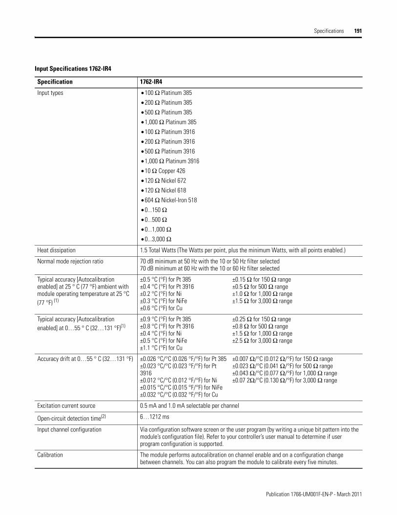
Specifications 191
Input Specifications 1762-IR4
Specification 1762-IR4
Input types • 100 Ω Platinum 385
• 200 Ω Platinum 385
• 500 Ω Platinum 385
• 1,000 Ω Platinum 385
• 100 Ω Platinum 3916
• 200 Ω Platinum 3916
• 500 Ω Platinum 3916
• 1,000 Ω Platinum 3916
• 10 Ω Copper 426
• 120 Ω Nickel 672
• 120 Ω Nickel 618
• 604 Ω Nickel-Iron 518
• 0...150 Ω• 0...500 Ω• 0...1,000 Ω• 0...3,000 Ω
Heat dissipation 1.5 Total Watts (The Watts per point, plus the minimum Watts, with all points enabled.)
Normal mode rejection ratio 70 dB minimum at 50 Hz with the 10 or 50 Hz filter selected70 dB minimum at 60 Hz with the 10 or 60 Hz filter selected
Typical accuracy [Autocalibration enabled] at 25 ° C (77 °F) ambient with module operating temperature at 25 °C (77 °F) (1)
±0.5 °C (°F) for Pt 385±0.4 °C (°F) for Pt 3916±0.2 °C (°F) for Ni±0.3 °C (°F) for NiFe±0.6 °C (°F) for Cu
±0.15 Ω for 150 Ω range±0.5 Ω for 500 Ω range±1.0 Ω for 1,000 Ω range±1.5 Ω for 3,000 Ω range
Typical accuracy [Autocalibration enabled] at 0…55 ° C (32…131 °F)(1)
±0.9 °C (°F) for Pt 385±0.8 °C (°F) for Pt 3916±0.4 °C (°F) for Ni±0.5 °C (°F) for NiFe±1.1 °C (°F) for Cu
±0.25 Ω for 150 Ω range±0.8 Ω for 500 Ω range±1.5 Ω for 1,000 Ω range±2.5 Ω for 3,000 Ω range
Accuracy drift at 0…55 ° C (32…131 °F) ±0.026 °C/°C (0.026 °F/°F) for Pt 385±0.023 °C/°C (0.023 °F/°F) for Pt 3916±0.012 °C/°C (0.012 °F/°F) for Ni±0.015 °C/°C (0.015 °F/°F) for NiFe±0.032 °C/°C (0.032 °F/°F) for Cu
±0.007 Ω/°C (0.012 Ω/°F) for 150 Ω range±0.023 Ω/°C (0.041 Ω/°F) for 500 Ω range±0.043 Ω/°C (0.077 Ω/°F) for 1,000 Ω range±0.07 2Ω/°C (0.130 Ω/°F) for 3,000 Ω range
Excitation current source 0.5 mA and 1.0 mA selectable per channel
Open-circuit detection time(2) 6…1212 ms
Input channel configuration Via configuration software screen or the user program (by writing a unique bit pattern into the module’s configuration file). Refer to your controller’s user manual to determine if user program configuration is supported.
Calibration The module performs autocalibration on channel enable and on a configuration change between channels. You can also program the module to calibrate every five minutes.
Publication 1766-UM001F-EN-P - March 2011
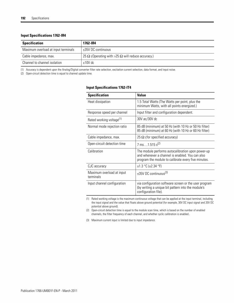
192 Specifications
Maximum overload at input terminals ±35V DC continuous
Cable impedance, max. 25 Ω (Operating with >25 Ω will reduce accuracy.)
Channel to channel isolation ±10V dc
(1) Accuracy is dependent upon the Analog/Digital converter filter rate selection, excitation current selection, data format, and input noise.(2) Open-circuit detection time is equal to channel update time.
Input Specifications 1762-IR4
Specification 1762-IR4
Input Specifications 1762-IT4
Specification Value
Heat dissipation 1.5 Total Watts (The Watts per point, plus the minimum Watts, with all points energized.)
Response speed per channel Input filter and configuration dependent.
Rated working voltage(1)
(1) Rated working voltage is the maximum continuous voltage that can be applied at the input terminal, including the input signal and the value that floats above ground potential (for example, 30V DC input signal and 20V DC potential above ground).
30V ac/30V dc
Normal mode rejection ratio 85 dB (minimum) at 50 Hz (with 10 Hz or 50 Hz filter)85 dB (minimum) at 60 Hz (with 10 Hz or 60 Hz filter)
Cable impedance, max. 25 Ω (for specified accuracy)
Open-circuit detection time 7 ms…1.515 s(2)
(2) Open-circuit detection time is equal to the module scan time, which is based on the number of enabled channels, the filter frequency of each channel, and whether cyclic calibration is enabled..
Calibration The module performs autocalibration upon power-up and whenever a channel is enabled. You can also program the module to calibrate every five minutes.
CJC accuracy ±1.3 °C (±2.34 °F)
Maximum overload at input terminals
±35V DC continuous(3)
(3) Maximum current input is limited due to input impedance.
Input channel configuration via configuration software screen or the user program (by writing a unique bit pattern into the module’s configuration file).
Publication 1766-UM001F-EN-P - March 2011
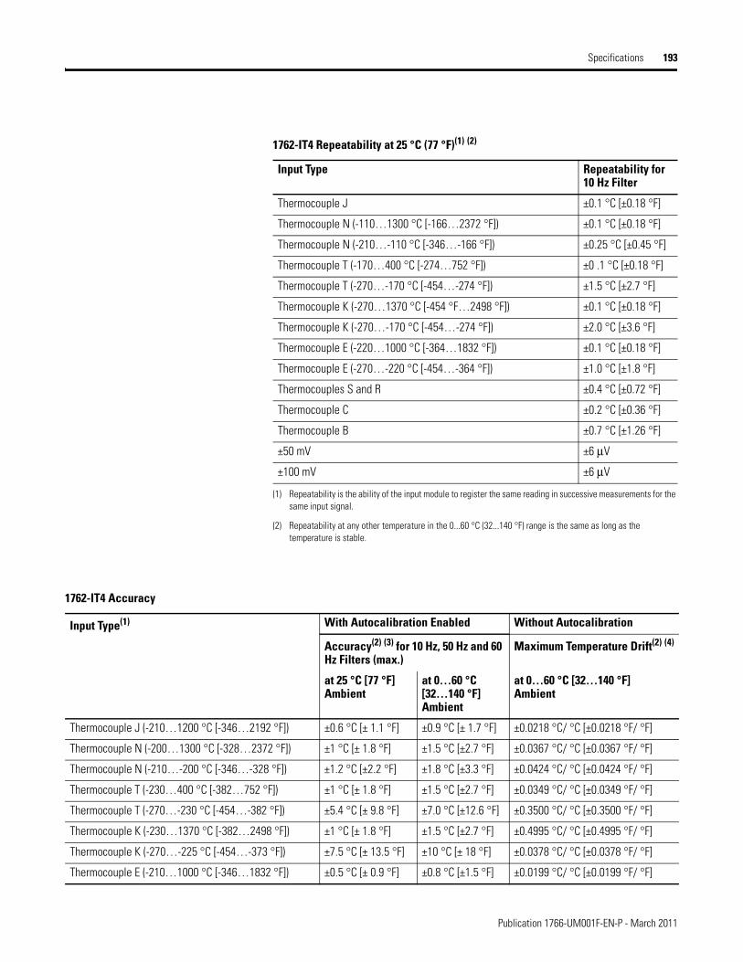
Specifications 193
1762-IT4 Repeatability at 25 °C (77 °F)(1) (2)
(1) Repeatability is the ability of the input module to register the same reading in successive measurements for the same input signal.
(2) Repeatability at any other temperature in the 0...60 °C (32...140 °F) range is the same as long as the temperature is stable.
Input Type Repeatability for 10 Hz Filter
Thermocouple J ±0.1 °C [±0.18 °F]
Thermocouple N (-110…1300 °C [-166…2372 °F]) ±0.1 °C [±0.18 °F]
Thermocouple N (-210…-110 °C [-346…-166 °F]) ±0.25 °C [±0.45 °F]
Thermocouple T (-170…400 °C [-274…752 °F]) ±0 .1 °C [±0.18 °F]
Thermocouple T (-270…-170 °C [-454…-274 °F]) ±1.5 °C [±2.7 °F]
Thermocouple K (-270…1370 °C [-454 °F…2498 °F]) ±0.1 °C [±0.18 °F]
Thermocouple K (-270…-170 °C [-454…-274 °F]) ±2.0 °C [±3.6 °F]
Thermocouple E (-220…1000 °C [-364…1832 °F]) ±0.1 °C [±0.18 °F]
Thermocouple E (-270…-220 °C [-454…-364 °F]) ±1.0 °C [±1.8 °F]
Thermocouples S and R ±0.4 °C [±0.72 °F]
Thermocouple C ±0.2 °C [±0.36 °F]
Thermocouple B ±0.7 °C [±1.26 °F]
±50 mV ±6 μV
±100 mV ±6 μV
1762-IT4 Accuracy
Input Type(1) With Autocalibration Enabled Without Autocalibration
Accuracy(2) (3) for 10 Hz, 50 Hz and 60 Hz Filters (max.)
Maximum Temperature Drift(2) (4)
at 25 °C [77 °F]Ambient
at 0…60 °C [32…140 °F] Ambient
at 0…60 °C [32…140 °F]Ambient
Thermocouple J (-210…1200 °C [-346…2192 °F]) ±0.6 °C [± 1.1 °F] ±0.9 °C [± 1.7 °F] ±0.0218 °C/ °C [±0.0218 °F/ °F]
Thermocouple N (-200…1300 °C [-328…2372 °F]) ±1 °C [± 1.8 °F] ±1.5 °C [±2.7 °F] ±0.0367 °C/ °C [±0.0367 °F/ °F]
Thermocouple N (-210…-200 °C [-346…-328 °F]) ±1.2 °C [±2.2 °F] ±1.8 °C [±3.3 °F] ±0.0424 °C/ °C [±0.0424 °F/ °F]
Thermocouple T (-230…400 °C [-382…752 °F]) ±1 °C [± 1.8 °F] ±1.5 °C [±2.7 °F] ±0.0349 °C/ °C [±0.0349 °F/ °F]
Thermocouple T (-270…-230 °C [-454…-382 °F]) ±5.4 °C [± 9.8 °F] ±7.0 °C [±12.6 °F] ±0.3500 °C/ °C [±0.3500 °F/ °F]
Thermocouple K (-230…1370 °C [-382…2498 °F]) ±1 °C [± 1.8 °F] ±1.5 °C [±2.7 °F] ±0.4995 °C/ °C [±0.4995 °F/ °F]
Thermocouple K (-270…-225 °C [-454…-373 °F]) ±7.5 °C [± 13.5 °F] ±10 °C [± 18 °F] ±0.0378 °C/ °C [±0.0378 °F/ °F]
Thermocouple E (-210…1000 °C [-346…1832 °F]) ±0.5 °C [± 0.9 °F] ±0.8 °C [±1.5 °F] ±0.0199 °C/ °C [±0.0199 °F/ °F]
Publication 1766-UM001F-EN-P - March 2011
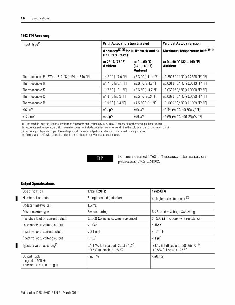
194 Specifications
Thermocouple E (-270…-210 °C [-454…-346 °F]) ±4.2 °C [± 7.6 °F] ±6.3 °C [±11.4 °F] ±0.2698 °C/ °C [±0.2698 °F/ °F]
Thermocouple R ±1.7 °C [± 3.1 °F] ±2.6 °C [± 4.7 °F] ±0.0613 °C/ °C [±0.0613 °F/ °F]
Thermocouple S ±1.7 °C [± 3.1 °F] ±2.6 °C [± 4.7 °F] ±0.0600 °C/ °C [±0.0600 °F/ °F]
Thermocouple C ±1.8 °C [±3.3 °F] ±3.5 °C [±6.3 °F] ±0.0899 °C/ °C [±0.0899 °F/ °F]
Thermocouple B ±3.0 °C [±5.4 °F] ±4.5 °C [±8.1 °F] ±0.1009 °C/ °C [±0.1009 °F/ °F]
±50 mV ±15 μV ±25 μV ±0.44μV/ °C [±0.80μV/ °F]
±100 mV ±20 μV ±30 μV ±0.69μV/ °C [±01.25μV/ °F]
(1) The module uses the National Institute of Standards and Technology (NIST) ITS-90 standard for thermocouple linearization.(2) Accuracy and temperature drift information does not include the affects of errors or drift in the cold junction compensation circuit.(3) Accuracy is dependent upon the analog/digital converter output rate selection, data format, and input noise.(4) Temperature drift with autocalibration is slightly better than without autocalibration.
1762-IT4 Accuracy
Input Type(1) With Autocalibration Enabled Without Autocalibration
Accuracy(2) (3) for 10 Hz, 50 Hz and 60 Hz Filters (max.)
Maximum Temperature Drift(2) (4)
at 25 °C [77 °F]Ambient
at 0…60 °C [32…140 °F] Ambient
at 0…60 °C [32…140 °F]Ambient
TIP For more detailed 1762-IT4 accuracy information, see publication 1762-UM002.
Output Specifications
Specification 1762-IF2OF2 1762-OF4
Number of outputs 2 single-ended (unipolar) 4 single-ended (unipolar)(2)
Update time (typical) 4.5 ms
D/A converter type Resistor string R-2R Ladder Voltage Switching
Resistive load on current output 0...500 Ω (includes wire resistance) 0...500 Ω (includes wire resistance)
Load range on voltage output > 1KΩ > 1KΩ
Reactive load, current output < 0.1 mH < 0.1 mH
Reactive load, voltage output < 1 μF < 1 μF
Typical overall accuracy(1) ±1.17% full scale at -20...65 °C (2) ±0.5% full scale at 25 °C
±1.17% full scale at -20...65 °C (2)
±0.5% full scale at 25 °C
Output ripplerange 0…500 Hz(referred to output range)
< ±0.1% < ±0.1%
Publication 1766-UM001F-EN-P - March 2011
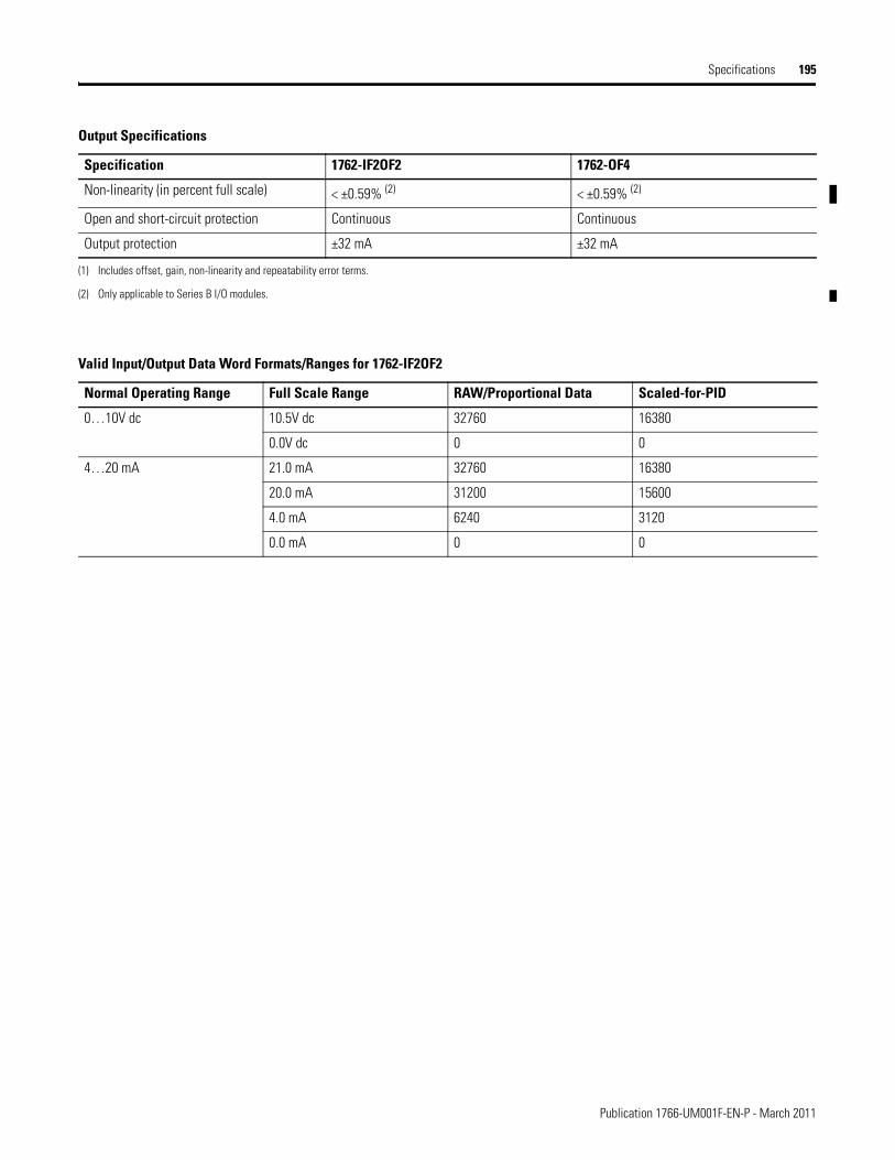
Specifications 195
Non-linearity (in percent full scale) < ±0.59% (2) < ±0.59% (2)
Open and short-circuit protection Continuous Continuous
Output protection ±32 mA ±32 mA
(1) Includes offset, gain, non-linearity and repeatability error terms.
(2) Only applicable to Series B I/O modules.
Output Specifications
Specification 1762-IF2OF2 1762-OF4
Valid Input/Output Data Word Formats/Ranges for 1762-IF2OF2
Normal Operating Range Full Scale Range RAW/Proportional Data Scaled-for-PID
0…10V dc 10.5V dc 32760 16380
0.0V dc 0 0
4…20 mA 21.0 mA 32760 16380
20.0 mA 31200 15600
4.0 mA 6240 3120
0.0 mA 0 0
Publication 1766-UM001F-EN-P - March 2011

196 Specifications
Notes:
Publication 1766-UM001F-EN-P - March 2011
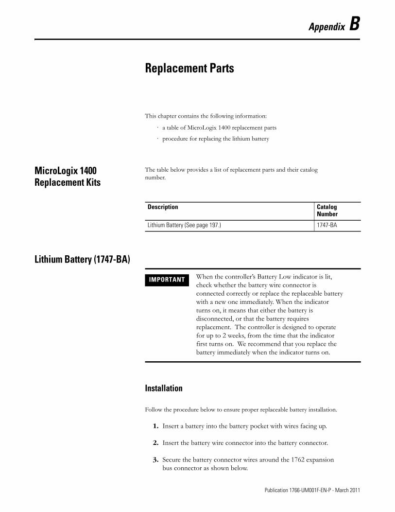
Appendix B
Replacement Parts
This chapter contains the following information:
· a table of MicroLogix 1400 replacement parts
· procedure for replacing the lithium battery
MicroLogix 1400 Replacement Kits
The table below provides a list of replacement parts and their catalog number.
Lithium Battery (1747-BA)
Installation
Follow the procedure below to ensure proper replaceable battery installation.
1. Insert a battery into the battery pocket with wires facing up.
2. Insert the battery wire connector into the battery connector.
3. Secure the battery connector wires around the 1762 expansion bus connector as shown below.
Description Catalog Number
Lithium Battery (See page 197.) 1747-BA
IMPORTANT When the controller’s Battery Low indicator is lit, check whether the battery wire connector is connected correctly or replace the replaceable battery with a new one immediately. When the indicator turns on, it means that either the battery is disconnected, or that the battery requires replacement. The controller is designed to operate for up to 2 weeks, from the time that the indicator first turns on. We recommend that you replace the battery immediately when the indicator turns on.
197 Publication 1766-UM001F-EN-P - March 2011
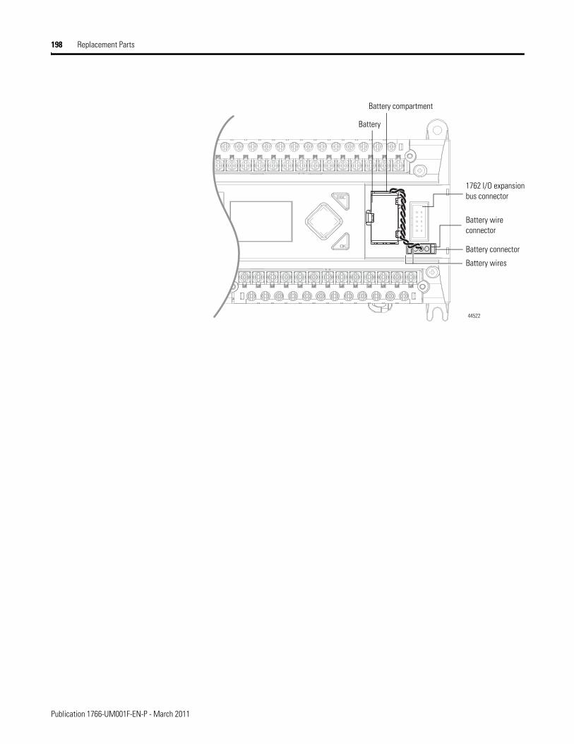
198 Replacement Parts
1762 I/O expansion bus connector
Battery wires
Battery compartment
Battery wire connector
Battery connector
44522
Battery
Publication 1766-UM001F-EN-P - March 2011
Replacement Parts 199
Battery Handling
Follow the procedure below to ensure proper battery operation and reduce personnel hazards.
· Use only for the intended operation.
· Do not ship or dispose of cells except according to recommended procedures.
· Do not ship on passenger aircraft.
Storage
Store lithium batteries in a cool, dry environment, typically 20 °C...2 5°C (68°F...77°F) and 40%...60% humidity. Store the batteries and a copy of the battery instruction sheet in the original container, away from flammable materials.
Transportation
One or Two Batteries
Each battery contains 0.23 g of lithium. Therefore, up to two batteries can be shipped together within the United States without restriction. Regulations governing shipment to or within other countries may differ.
Three or More Batteries
Procedures for the transportation of three or more batteries shipped together within the United States are specified by the Department of Transportation (DOT) in the Code of Federal Regulations, CFR49, “Transportation.” An exemption to these regulations, DOT - E7052, covers the transport of certain hazardous materials classified as flammable solids. This exemption authorizes
ATTENTION • Do not charge the batteries. An explosion could result or the cells could overheat causing burns.
• Do not open, puncture, crush, or otherwise mutilate the batteries. A possibility of an explosion exists and/or toxic, corrosive, and flammable liquids would be exposed.
• Do not incinerate or expose the batteries to high temperatures. Do not attempt to solder batteries. An explosion could result.
• Do not short positive and negative terminals together. Excessive heat can build up and cause severe burns.
Publication 1766-UM001F-EN-P - March 2011
200 Replacement Parts
transport of lithium batteries by motor vehicle, rail freight, cargo vessel, and cargo-only aircraft, providing certain conditions are met. Transport by passenger aircraft is not permitted.
A special provision of DOT-E7052 (11th Rev., October 21, 1982, par. 8-a) provides that:
“Persons that receive cell and batteries covered by this exemption may reship them pursuant to the provisions of 49 CFR 173.22a in any of these packages authorized in this exemption including those in which they were received.”
The Code of Federal Regulations, 49 CFR 173.22a, relates to the use of packaging authorized under exemptions. In part, it requires that you must maintain a copy of the exemption at each facility where the packaging is being used in connection with shipment under the exemption.
Shipment of depleted batteries for disposal may be subject to specific regulation of the countries involved or to regulations endorsed by those countries, such as the IATA Articles Regulations of the International Air Transport Association, Geneva, Switzerland.
IMPORTANT Regulations for transportation of lithium batteries are periodically revised. Refer to http://www.dot.gov for the latest shipping information.
Publication 1766-UM001F-EN-P - March 2011

Replacement Parts 201
Disposal
For disposal, batteries must be packaged and shipped in accordance with transportation regulations, to a proper disposal site. The U.S. Department of Transportation authorizes shipment of “Lithium batteries for disposal” by motor vehicle only in regulation 173.1015 of CFR 49 (effective January 5, 1983). For additional information contact:
U.S. Department of TransportationResearch and Special Programs Administration400 Seventh Street, S.W.Washington, D.C. 20590
Although the Environmental Protection Agency at this time has no regulations specific to lithium batteries, the material contained may be considered toxic, reactive, or corrosive. The person disposing of the material is responsible for any hazard created in doing so. State and local regulations may exist regarding the disposal of these materials.
For a lithium battery product safety data sheet, contact the manufacturer:
Sanyo Energy Corporation Tadarand U.S. Battery Division2001 Sanyo Avenue 2 Seaview Blvd.San Diego, CA 92173 Port Washington, NY 11050(619) 661-4801 (516) 621-4980
ATTENTION Do not incinerate or dispose of lithium batteries in general trash collection. Explosion or violent rupture is possible. Batteries should be collected for disposal in a manner to prevent against short-circuiting, compacting, or destruction of case integrity and hermetic seal.
Publication 1766-UM001F-EN-P - March 2011

202 Replacement Parts
Notes:
Publication 1766-UM001F-EN-P - March 2011
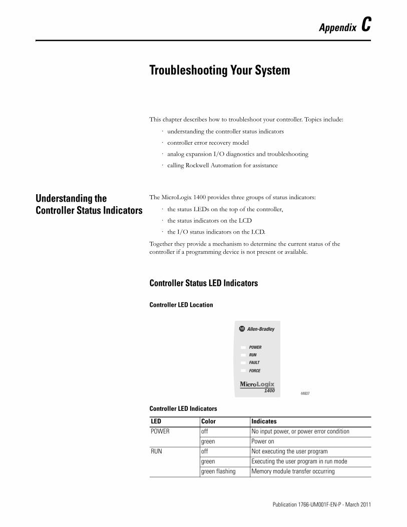
Appendix C
Troubleshooting Your System
This chapter describes how to troubleshoot your controller. Topics include:
· understanding the controller status indicators
· controller error recovery model
· analog expansion I/O diagnostics and troubleshooting
· calling Rockwell Automation for assistance
Understanding the Controller Status Indicators
The MicroLogix 1400 provides three groups of status indicators:
· the status LEDs on the top of the controller,
· the status indicators on the LCD
· the I/O status indicators on the LCD.
Together they provide a mechanism to determine the current status of the controller if a programming device is not present or available.
Controller Status LED Indicators
Controller LED Location
Controller LED Indicators
LED Color IndicatesPOWER off No input power, or power error condition
green Power on
RUN off Not executing the user program
green Executing the user program in run mode
green flashing Memory module transfer occurring
POWER
RUN
FAULT
FORCE
140044607
203 Publication 1766-UM001F-EN-P - March 2011
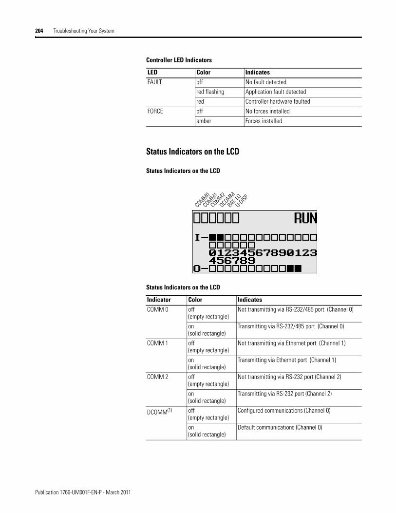
204 Troubleshooting Your System
Status Indicators on the LCD
Status Indicators on the LCD
FAULT off No fault detected
red flashing Application fault detected
red Controller hardware faulted
FORCE off No forces installed
amber Forces installed
Status Indicators on the LCD
Indicator Color IndicatesCOMM 0 off
(empty rectangle)Not transmitting via RS-232/485 port (Channel 0)
on(solid rectangle)
Transmitting via RS-232/485 port (Channel 0)
COMM 1 off (empty rectangle)
Not transmitting via Ethernet port (Channel 1)
on(solid rectangle)
Transmitting via Ethernet port (Channel 1)
COMM 2 off (empty rectangle)
Not transmitting via RS-232 port (Channel 2)
on(solid rectangle)
Transmitting via RS-232 port (Channel 2)
DCOMM(1) off (empty rectangle)
Configured communications (Channel 0)
on(solid rectangle)
Default communications (Channel 0)
Controller LED Indicators
LED Color Indicates
COMM0
COMM1
DCOMM
BAT. LO
U-DISPCOMM2
Publication 1766-UM001F-EN-P - March 2011
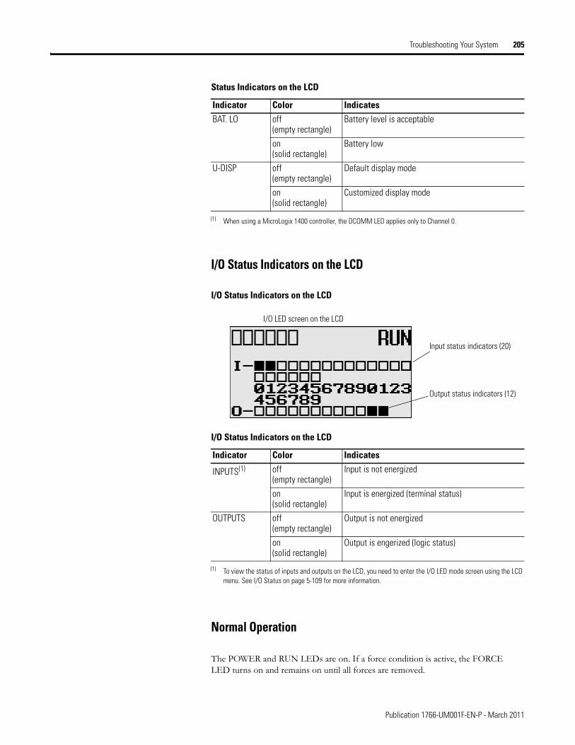
Troubleshooting Your System 205
I/O Status Indicators on the LCD
I/O Status Indicators on the LCD
Normal Operation
The POWER and RUN LEDs are on. If a force condition is active, the FORCE LED turns on and remains on until all forces are removed.
BAT. LO off (empty rectangle)
Battery level is acceptable
on(solid rectangle)
Battery low
U-DISP off (empty rectangle)
Default display mode
on(solid rectangle)
Customized display mode
(1) When using a MicroLogix 1400 controller, the DCOMM LED applies only to Channel 0.
I/O Status Indicators on the LCD
Indicator Color Indicates
INPUTS(1)
(1) To view the status of inputs and outputs on the LCD, you need to enter the I/O LED mode screen using the LCD menu. See I/O Status on page 5-109 for more information.
off (empty rectangle)
Input is not energized
on(solid rectangle)
Input is energized (terminal status)
OUTPUTS off (empty rectangle)
Output is not energized
on(solid rectangle)
Output is engerized (logic status)
Status Indicators on the LCD
Indicator Color Indicates
Output status indicators (12)
Input status indicators (20)
I/O LED screen on the LCD
Publication 1766-UM001F-EN-P - March 2011
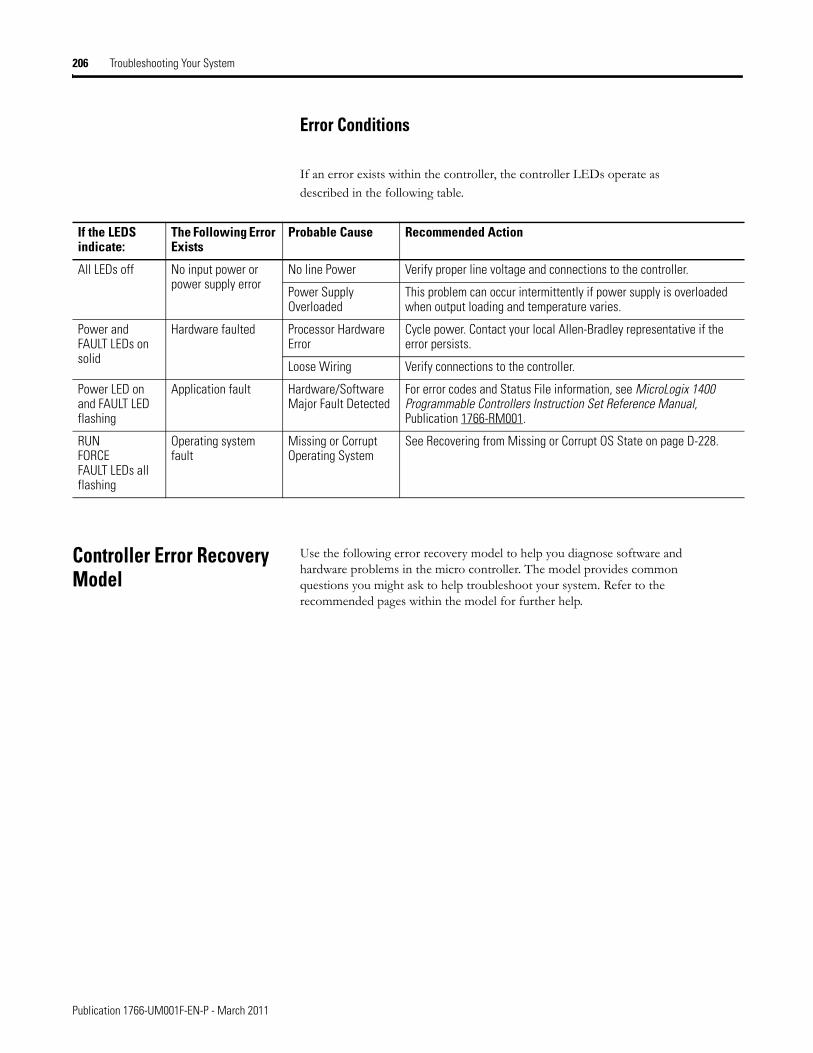
206 Troubleshooting Your System
Error Conditions
If an error exists within the controller, the controller LEDs operate as described in the following table.
Controller Error Recovery Model
Use the following error recovery model to help you diagnose software and hardware problems in the micro controller. The model provides common questions you might ask to help troubleshoot your system. Refer to the recommended pages within the model for further help.
If the LEDS indicate:
The Following Error Exists
Probable Cause Recommended Action
All LEDs off No input power or power supply error
No line Power Verify proper line voltage and connections to the controller.
Power Supply Overloaded
This problem can occur intermittently if power supply is overloaded when output loading and temperature varies.
Power and FAULT LEDs on solid
Hardware faulted Processor Hardware Error
Cycle power. Contact your local Allen-Bradley representative if the error persists.
Loose Wiring Verify connections to the controller.
Power LED on and FAULT LED flashing
Application fault Hardware/Software Major Fault Detected
For error codes and Status File information, see MicroLogix 1400 Programmable Controllers Instruction Set Reference Manual, Publication 1766-RM001.
RUNFORCEFAULT LEDs all flashing
Operating system fault
Missing or Corrupt Operating System
See Recovering from Missing or Corrupt OS State on page D-228.
Publication 1766-UM001F-EN-P - March 2011
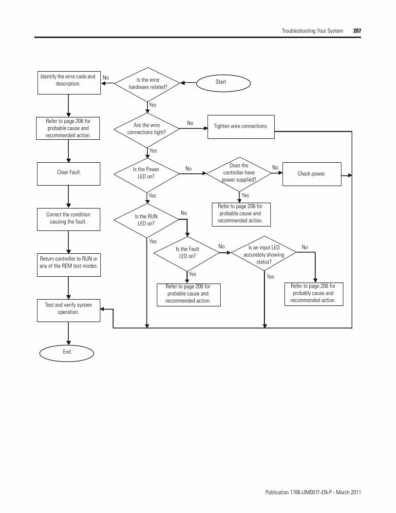
Troubleshooting Your System 207
Identify the error code and description.
Refer to page 206 for probable cause and
recommended action.
Clear Fault.
Correct the condition causing the fault.
Return controller to RUN or any of the REM test modes.
Test and verify system operation.
Refer to page 206 for probable cause and
recommended action.
Is the Fault LED on?
Is the RUN LED on?
Is the Power LED on?
Are the wire connections tight?
Tighten wire connections.
Does the controller have
power supplied?Check power.
Refer to page 206 for probable cause and
recommended action.
Is an input LED accurately showing
status?
Refer to page 206 for probably cause and
recommended action.
Is the error hardware related?
StartNo
No
No No
No
No No
YesYes
Yes
Yes
Yes
Yes
End
Yes
Publication 1766-UM001F-EN-P - March 2011
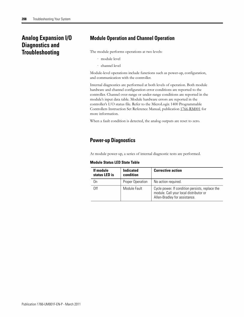
208 Troubleshooting Your System
Analog Expansion I/O Diagnostics and Troubleshooting
Module Operation and Channel Operation
The module performs operations at two levels:
· module level
· channel level
Module-level operations include functions such as power-up, configuration, and communication with the controller.
Internal diagnostics are performed at both levels of operation. Both module hardware and channel configuration error conditions are reported to the controller. Channel over-range or under-range conditions are reported in the module’s input data table. Module hardware errors are reported in the controller’s I/O status file. Refer to the MicroLogix 1400 Programmable Controllers Instruction Set Reference Manual, publication 1766-RM001 for more information.
When a fault condition is detected, the analog outputs are reset to zero.
Power-up Diagnostics
At module power-up, a series of internal diagnostic tests are performed.
Module Status LED State Table
If module status LED is
Indicated condition
Corrective action
On Proper Operation No action required.
Off Module Fault Cycle power. If condition persists, replace the module. Call your local distributor or Allen-Bradley for assistance.
Publication 1766-UM001F-EN-P - March 2011
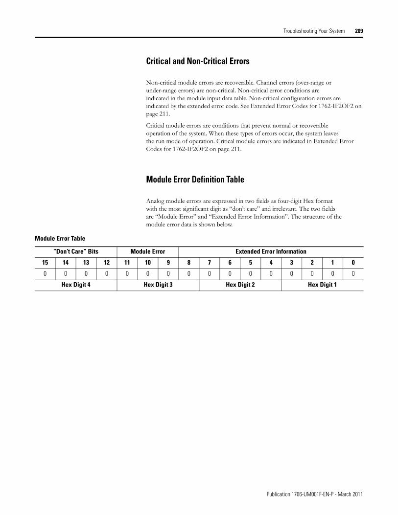
Troubleshooting Your System 209
Critical and Non-Critical Errors
Non-critical module errors are recoverable. Channel errors (over-range or under-range errors) are non-critical. Non-critical error conditions are indicated in the module input data table. Non-critical configuration errors are indicated by the extended error code. See Extended Error Codes for 1762-IF2OF2 on page 211.
Critical module errors are conditions that prevent normal or recoverable operation of the system. When these types of errors occur, the system leaves the run mode of operation. Critical module errors are indicated in Extended Error Codes for 1762-IF2OF2 on page 211.
Module Error Definition Table
Analog module errors are expressed in two fields as four-digit Hex format with the most significant digit as “don’t care” and irrelevant. The two fields are “Module Error” and “Extended Error Information”. The structure of the module error data is shown below.
Module Error Table
“Don’t Care” Bits Module Error Extended Error Information
15 14 13 12 11 10 9 8 7 6 5 4 3 2 1 0
0 0 0 0 0 0 0 0 0 0 0 0 0 0 0 0
Hex Digit 4 Hex Digit 3 Hex Digit 2 Hex Digit 1
Publication 1766-UM001F-EN-P - March 2011
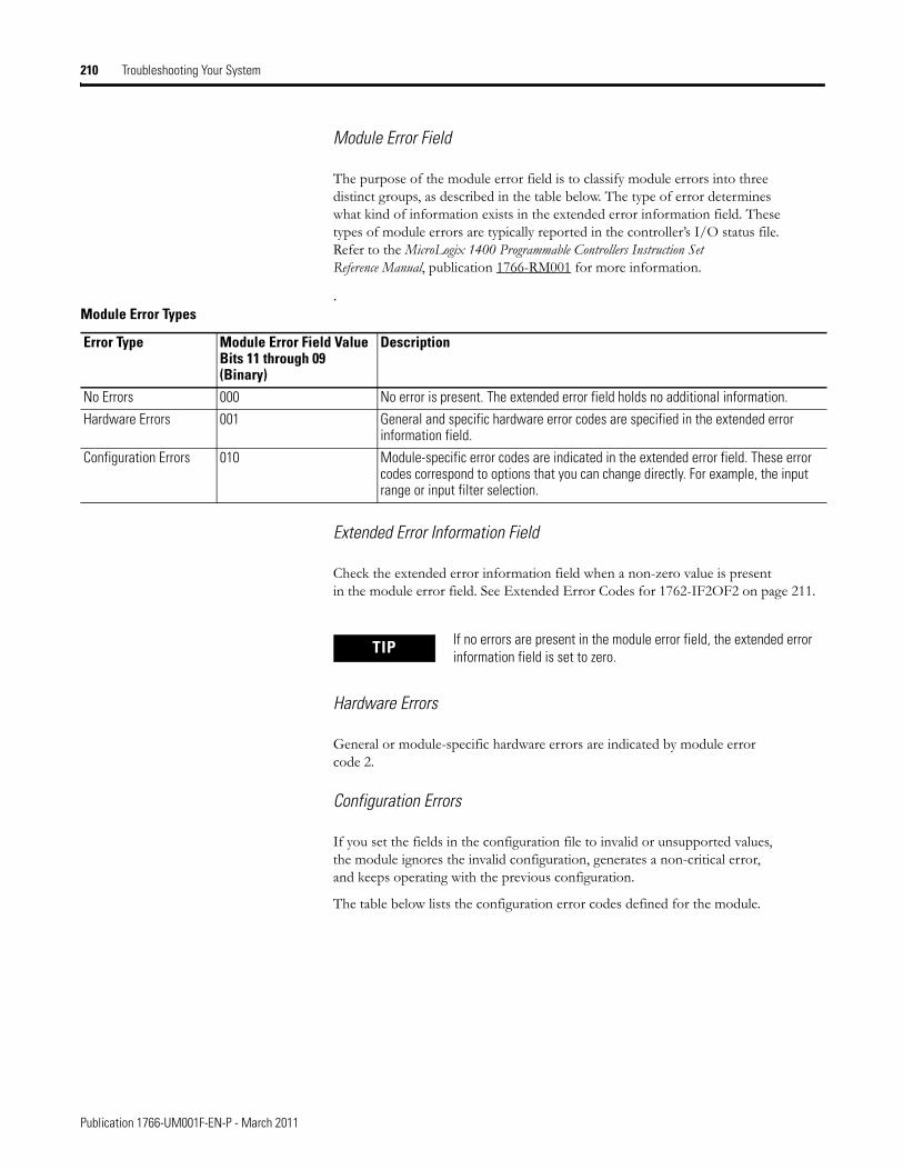
210 Troubleshooting Your System
Module Error Field
The purpose of the module error field is to classify module errors into three distinct groups, as described in the table below. The type of error determines what kind of information exists in the extended error information field. These types of module errors are typically reported in the controller’s I/O status file. Refer to the MicroLogix 1400 Programmable Controllers Instruction Set Reference Manual, publication 1766-RM001 for more information.
.
Extended Error Information Field
Check the extended error information field when a non-zero value is present in the module error field. See Extended Error Codes for 1762-IF2OF2 on page 211.
Hardware Errors
General or module-specific hardware errors are indicated by module error code 2.
Configuration Errors
If you set the fields in the configuration file to invalid or unsupported values, the module ignores the invalid configuration, generates a non-critical error, and keeps operating with the previous configuration.
The table below lists the configuration error codes defined for the module.
Module Error Types
Error Type Module Error Field ValueBits 11 through 09(Binary)
Description
No Errors 000 No error is present. The extended error field holds no additional information.
Hardware Errors 001 General and specific hardware error codes are specified in the extended error information field.
Configuration Errors 010 Module-specific error codes are indicated in the extended error field. These error codes correspond to options that you can change directly. For example, the input range or input filter selection.
TIP If no errors are present in the module error field, the extended error information field is set to zero.
Publication 1766-UM001F-EN-P - March 2011
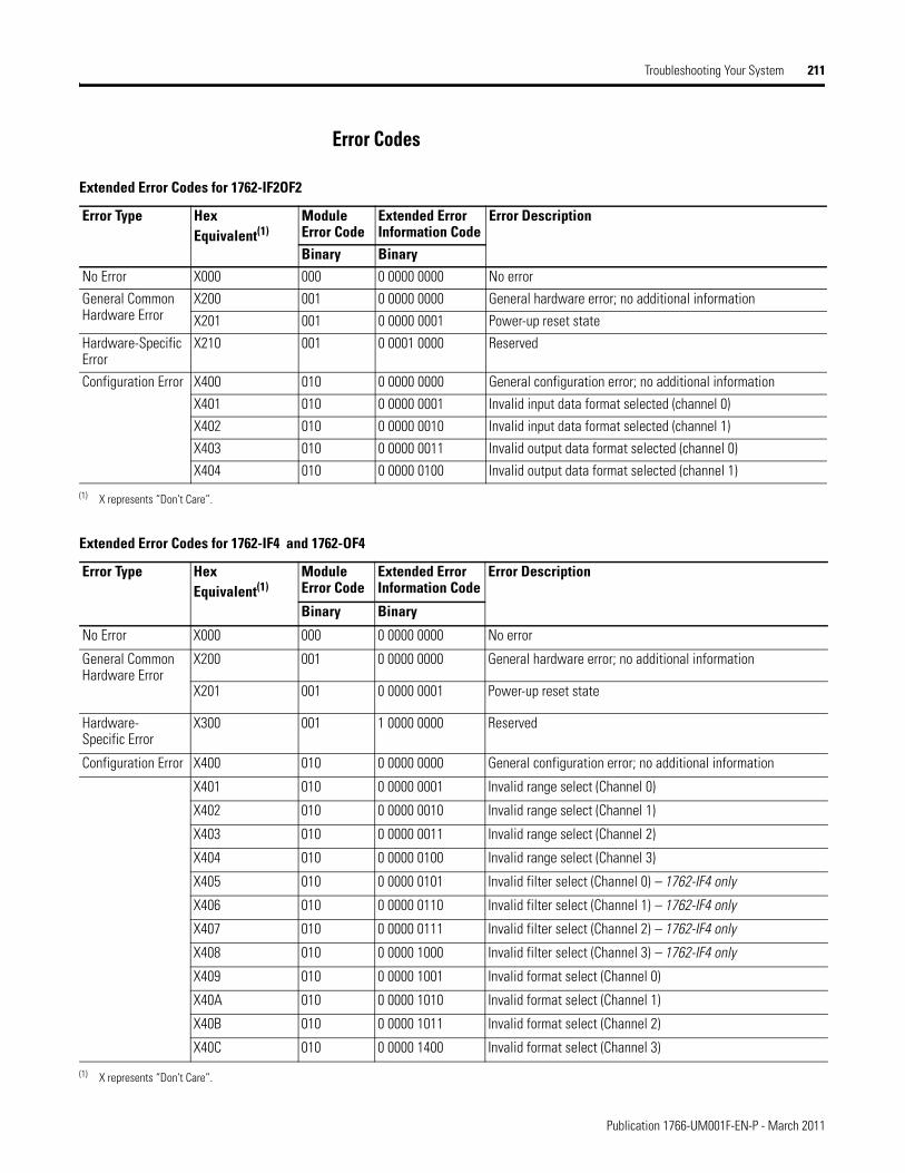
Troubleshooting Your System 211
Error Codes
Extended Error Codes for 1762-IF2OF2
Error Type Hex Equivalent(1)
Module Error Code
Extended Error Information Code
Error Description
Binary BinaryNo Error X000 000 0 0000 0000 No error
General Common Hardware Error
X200 001 0 0000 0000 General hardware error; no additional information
X201 001 0 0000 0001 Power-up reset state
Hardware-Specific Error
X210 001 0 0001 0000 Reserved
Configuration Error X400 010 0 0000 0000 General configuration error; no additional information
X401 010 0 0000 0001 Invalid input data format selected (channel 0)
X402 010 0 0000 0010 Invalid input data format selected (channel 1)
X403 010 0 0000 0011 Invalid output data format selected (channel 0)
X404 010 0 0000 0100 Invalid output data format selected (channel 1)
(1) X represents “Don’t Care”.
Extended Error Codes for 1762-IF4 and 1762-OF4
Error Type Hex Equivalent(1)
Module Error Code
Extended Error Information Code
Error Description
Binary Binary
No Error X000 000 0 0000 0000 No error
General Common Hardware Error
X200 001 0 0000 0000 General hardware error; no additional information
X201 001 0 0000 0001 Power-up reset state
Hardware-Specific Error
X300 001 1 0000 0000 Reserved
Configuration Error X400 010 0 0000 0000 General configuration error; no additional information
X401 010 0 0000 0001 Invalid range select (Channel 0)
X402 010 0 0000 0010 Invalid range select (Channel 1)
X403 010 0 0000 0011 Invalid range select (Channel 2)
X404 010 0 0000 0100 Invalid range select (Channel 3)
X405 010 0 0000 0101 Invalid filter select (Channel 0) – 1762-IF4 only
X406 010 0 0000 0110 Invalid filter select (Channel 1) – 1762-IF4 only
X407 010 0 0000 0111 Invalid filter select (Channel 2) – 1762-IF4 only
X408 010 0 0000 1000 Invalid filter select (Channel 3) – 1762-IF4 only
X409 010 0 0000 1001 Invalid format select (Channel 0)
X40A 010 0 0000 1010 Invalid format select (Channel 1)
X40B 010 0 0000 1011 Invalid format select (Channel 2)
X40C 010 0 0000 1400 Invalid format select (Channel 3)
(1) X represents “Don’t Care”.
Publication 1766-UM001F-EN-P - March 2011
212 Troubleshooting Your System
Calling Rockwell Automation for Assistance
If you need to contact Rockwell Automation or local distributor for assistance, it is helpful to obtain the following (prior to calling):
· controller type, series letter, revision letter, and firmware (FRN) number of the controller
· controller indicator status
· controller error codes (Refer to MicroLogix 1400 Programmable Controllers Instruction Set Reference Manual, Publication 1766-RM001 for error code information.)
Publication 1766-UM001F-EN-P - March 2011
Appendix D
Using ControlFLASH to Upgrade Your Operating System
The operating system (OS) can be upgraded through the Ethernet port of the controller. In order to download a new operating system, you must have the following:
• ControlFLASH Upgrade Kit containing the new OSGo to http://www.ab.com/programmablecontrol/plc/micrologix/downloads.html to download the upgrade kit.
• a Windows 95, Windows 98, Windows 2000, Windows NT, Windows XP, or Windows Vista based computer to run the download software.
The ControlFLASH Upgrade Kit includes:
• the operating system upgrade to be downloaded.
• the ControlFLASH programming tool, along with its support drivers and on-line help.
Preparing for Firmware Upgrade
Before upgrading the controller’s operating system (OS), you must:
• install ControlFLASH software on your personal computer.
• prepare the controller for updating.
Install ControlFLASH Software
Double click the ControlFLASH.msi file to install the operating system upgrade.
If a ControlFLASH directory does not already exist, one is created in your Program Files directory.
213 Publication 1766-UM001F-EN-P - March 2011
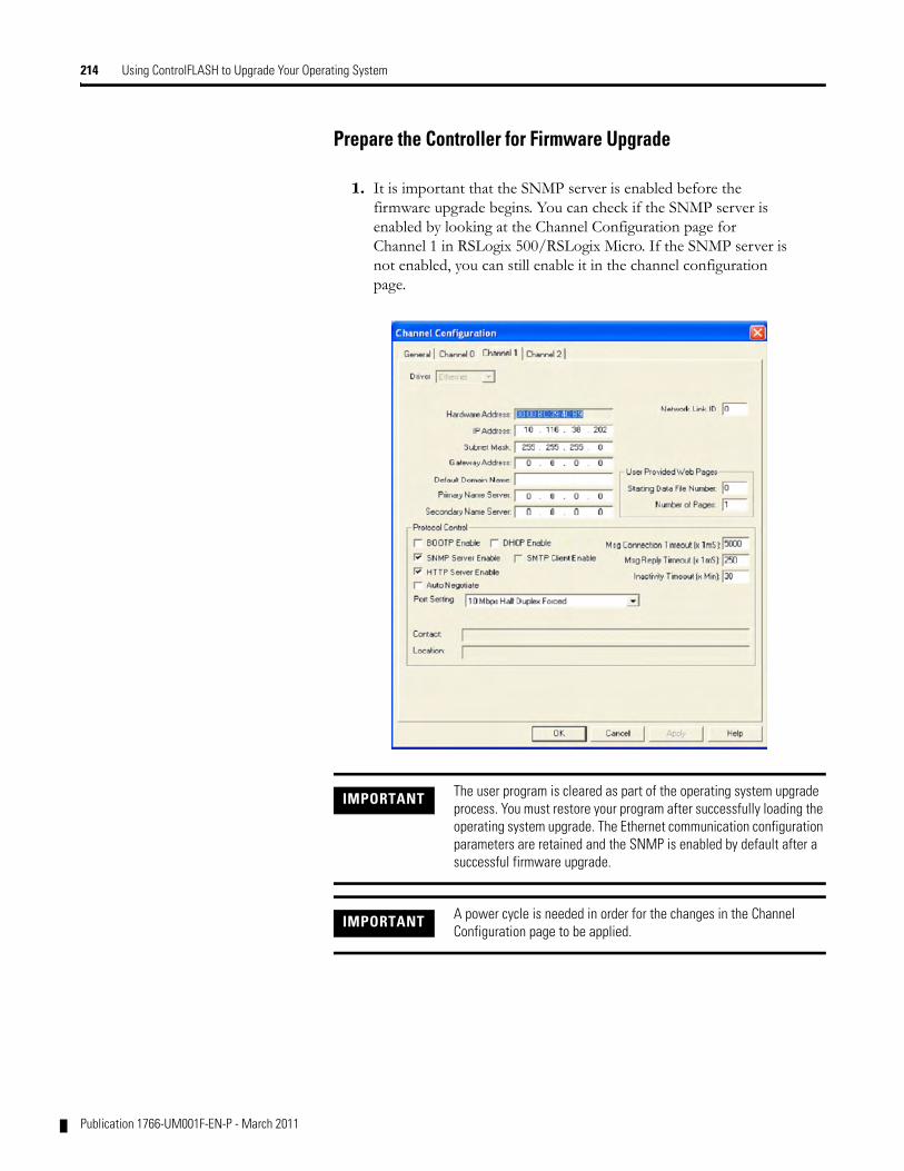
214 Using ControlFLASH to Upgrade Your Operating System
Prepare the Controller for Firmware Upgrade
1. It is important that the SNMP server is enabled before the firmware upgrade begins. You can check if the SNMP server is enabled by looking at the Channel Configuration page for Channel 1 in RSLogix 500/RSLogix Micro. If the SNMP server is not enabled, you can still enable it in the channel configuration page.
IMPORTANT The user program is cleared as part of the operating system upgrade process. You must restore your program after successfully loading the operating system upgrade. The Ethernet communication configuration parameters are retained and the SNMP is enabled by default after a successful firmware upgrade.
IMPORTANT A power cycle is needed in order for the changes in the Channel Configuration page to be applied.
Publication 1766-UM001F-EN-P - March 2011
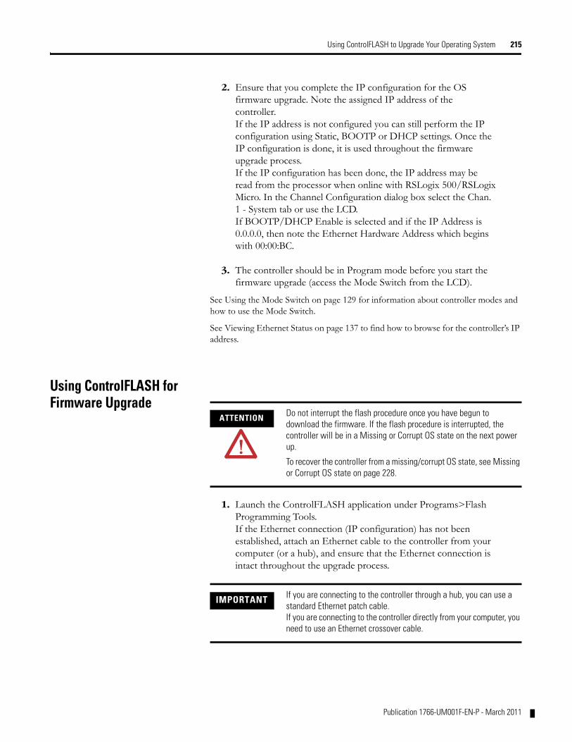
Using ControlFLASH to Upgrade Your Operating System 215
2. Ensure that you complete the IP configuration for the OS firmware upgrade. Note the assigned IP address of the controller. If the IP address is not configured you can still perform the IP configuration using Static, BOOTP or DHCP settings. Once the IP configuration is done, it is used throughout the firmware upgrade process. If the IP configuration has been done, the IP address may be read from the processor when online with RSLogix 500/RSLogix Micro. In the Channel Configuration dialog box select the Chan. 1 - System tab or use the LCD. If BOOTP/DHCP Enable is selected and if the IP Address is 0.0.0.0, then note the Ethernet Hardware Address which begins with 00:00:BC.
3. The controller should be in Program mode before you start the firmware upgrade (access the Mode Switch from the LCD).
See Using the Mode Switch on page 129 for information about controller modes and how to use the Mode Switch.
See Viewing Ethernet Status on page 137 to find how to browse for the controller’s IP address.
Using ControlFLASH for Firmware Upgrade
1. Launch the ControlFLASH application under Programs>Flash Programming Tools.If the Ethernet connection (IP configuration) has not been established, attach an Ethernet cable to the controller from your computer (or a hub), and ensure that the Ethernet connection is intact throughout the upgrade process.
ATTENTION Do not interrupt the flash procedure once you have begun to download the firmware. If the flash procedure is interrupted, the controller will be in a Missing or Corrupt OS state on the next power up.
To recover the controller from a missing/corrupt OS state, see Missing or Corrupt OS state on page 228.
IMPORTANT If you are connecting to the controller through a hub, you can use a standard Ethernet patch cable.If you are connecting to the controller directly from your computer, you need to use an Ethernet crossover cable.
Publication 1766-UM001F-EN-P - March 2011
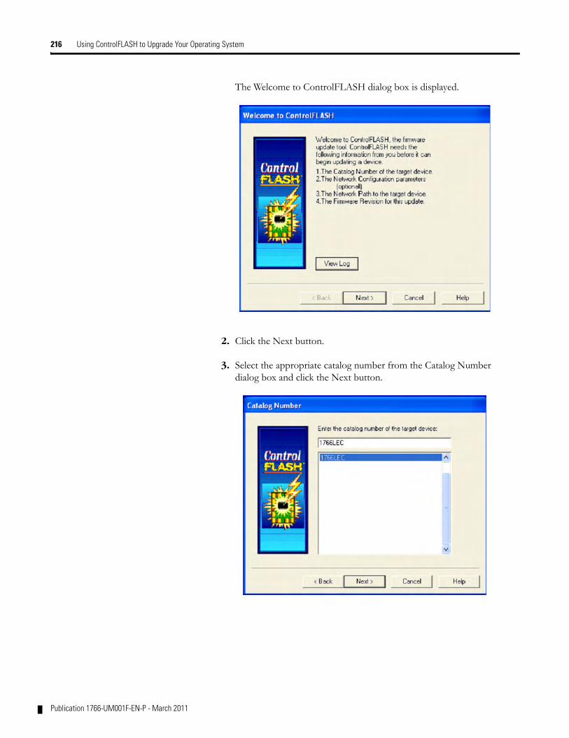
216 Using ControlFLASH to Upgrade Your Operating System
The Welcome to ControlFLASH dialog box is displayed.
2. Click the Next button.
3. Select the appropriate catalog number from the Catalog Number dialog box and click the Next button.
Publication 1766-UM001F-EN-P - March 2011
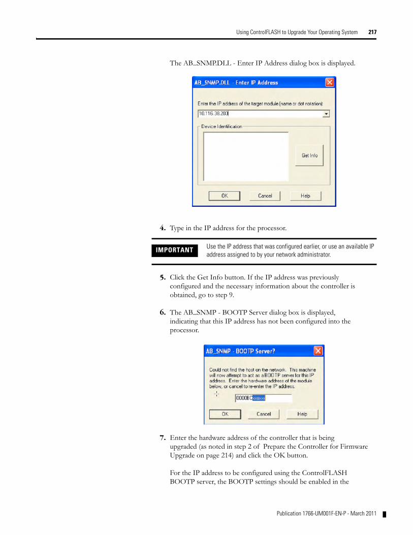
Using ControlFLASH to Upgrade Your Operating System 217
The AB_SNMP.DLL - Enter IP Address dialog box is displayed.
4. Type in the IP address for the processor.
5. Click the Get Info button. If the IP address was previously configured and the necessary information about the controller is obtained, go to step 9.
6. The AB_SNMP - BOOTP Server dialog box is displayed, indicating that this IP address has not been configured into the processor.
7. Enter the hardware address of the controller that is being upgraded (as noted in step 2 of Prepare the Controller for Firmware Upgrade on page 214) and click the OK button.
For the IP address to be configured using the ControlFLASH BOOTP server, the BOOTP settings should be enabled in the
IMPORTANT Use the IP address that was configured earlier, or use an available IP address assigned to by your network administrator.
Publication 1766-UM001F-EN-P - March 2011
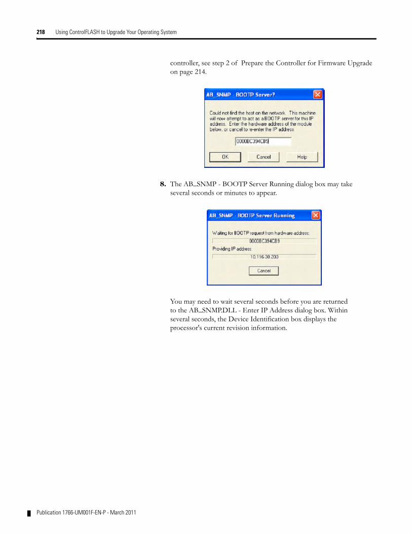
218 Using ControlFLASH to Upgrade Your Operating System
controller, see step 2 of Prepare the Controller for Firmware Upgrade on page 214.
8. The AB_SNMP - BOOTP Server Running dialog box may take several seconds or minutes to appear.
You may need to wait several seconds before you are returned to the AB_SNMP.DLL - Enter IP Address dialog box. Within several seconds, the Device Identification box displays the processor's current revision information.
Publication 1766-UM001F-EN-P - March 2011
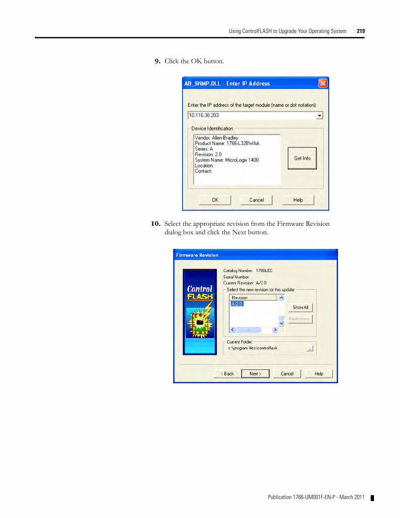
Using ControlFLASH to Upgrade Your Operating System 219
9. Click the OK button.
10. Select the appropriate revision from the Firmware Revision dialog box and click the Next button.
Publication 1766-UM001F-EN-P - March 2011
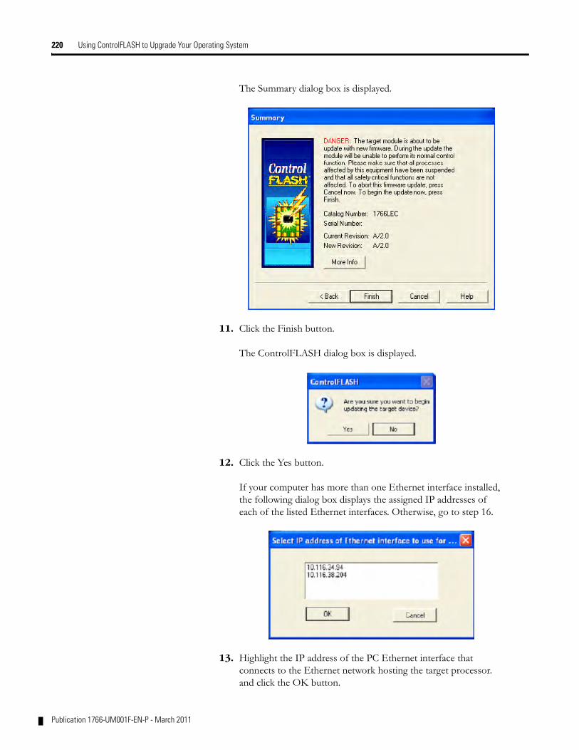
220 Using ControlFLASH to Upgrade Your Operating System
The Summary dialog box is displayed.
11. Click the Finish button.
The ControlFLASH dialog box is displayed.
12. Click the Yes button.
If your computer has more than one Ethernet interface installed, the following dialog box displays the assigned IP addresses of each of the listed Ethernet interfaces. Otherwise, go to step 16.
13. Highlight the IP address of the PC Ethernet interface that connects to the Ethernet network hosting the target processor. and click the OK button.
Publication 1766-UM001F-EN-P - March 2011
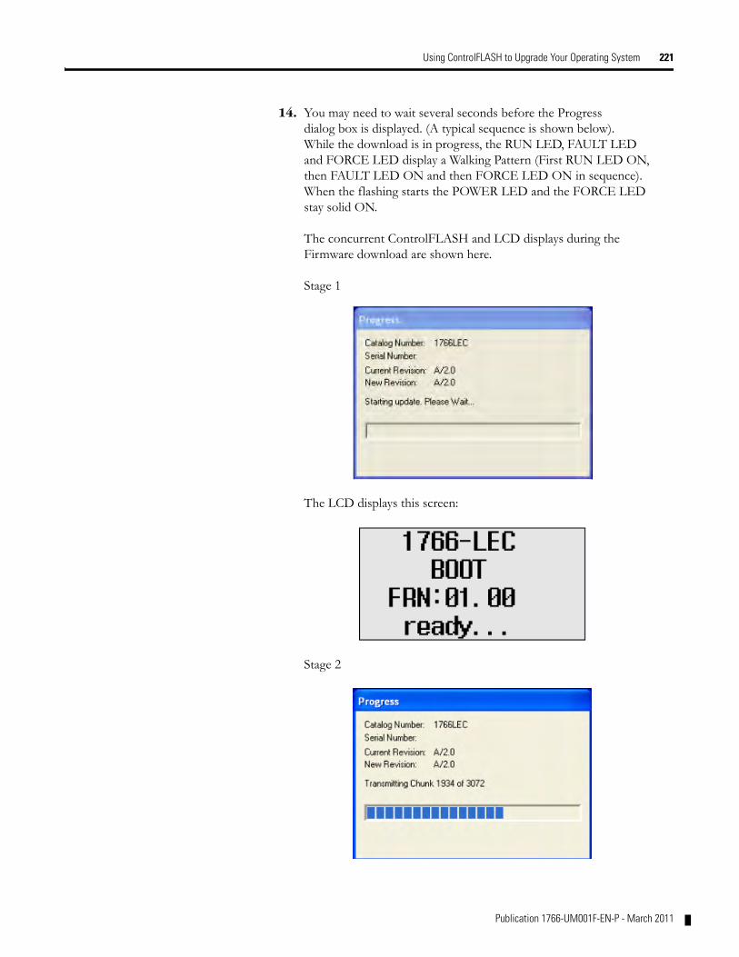
Using ControlFLASH to Upgrade Your Operating System 221
14. You may need to wait several seconds before the Progress dialog box is displayed. (A typical sequence is shown below). While the download is in progress, the RUN LED, FAULT LED and FORCE LED display a Walking Pattern (First RUN LED ON, then FAULT LED ON and then FORCE LED ON in sequence). When the flashing starts the POWER LED and the FORCE LED stay solid ON.
The concurrent ControlFLASH and LCD displays during the Firmware download are shown here.
Stage 1
The LCD displays this screen:
Stage 2
Publication 1766-UM001F-EN-P - March 2011
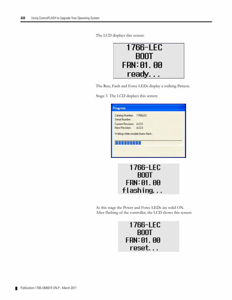
222 Using ControlFLASH to Upgrade Your Operating System
The LCD displays this screen:
The Run, Fault and Force LEDs display a walking Pattern.
Stage 3 The LCD displays this screen:
At this stage the Power and Force LEDs are solid ON.After flashing of the controller, the LCD shows this screen:
Publication 1766-UM001F-EN-P - March 2011
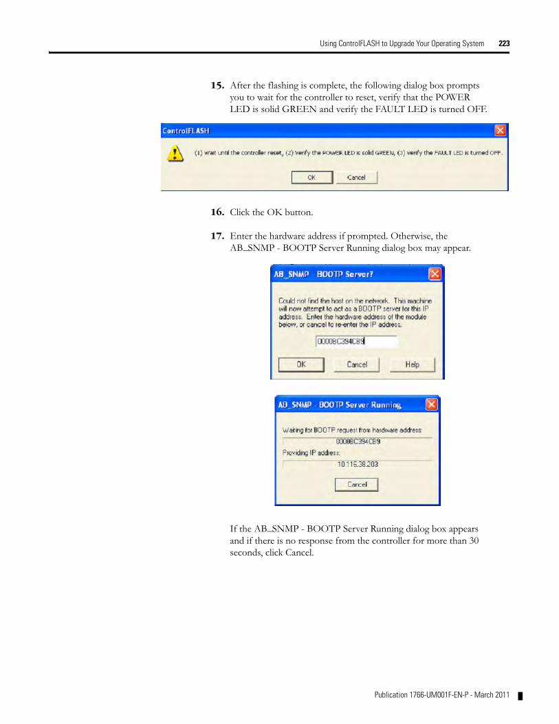
Using ControlFLASH to Upgrade Your Operating System 223
15. After the flashing is complete, the following dialog box prompts you to wait for the controller to reset, verify that the POWER LED is solid GREEN and verify the FAULT LED is turned OFF.
16. Click the OK button.
17. Enter the hardware address if prompted. Otherwise, the AB_SNMP - BOOTP Server Running dialog box may appear.
If the AB_SNMP - BOOTP Server Running dialog box appears and if there is no response from the controller for more than 30 seconds, click Cancel.
Publication 1766-UM001F-EN-P - March 2011
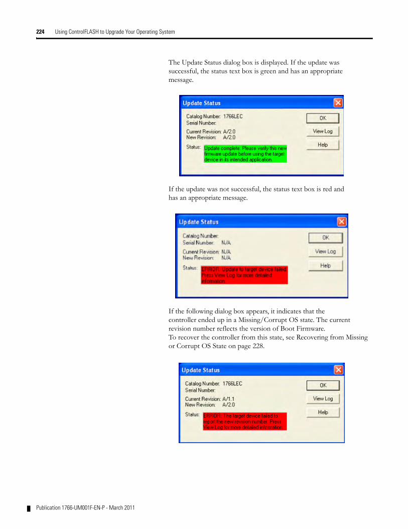
224 Using ControlFLASH to Upgrade Your Operating System
The Update Status dialog box is displayed. If the update was successful, the status text box is green and has an appropriate message.
If the update was not successful, the status text box is red and has an appropriate message.
If the following dialog box appears, it indicates that the controller ended up in a Missing/Corrupt OS state. The current revision number reflects the version of Boot Firmware. To recover the controller from this state, see Recovering from Missing or Corrupt OS State on page 228.
Publication 1766-UM001F-EN-P - March 2011
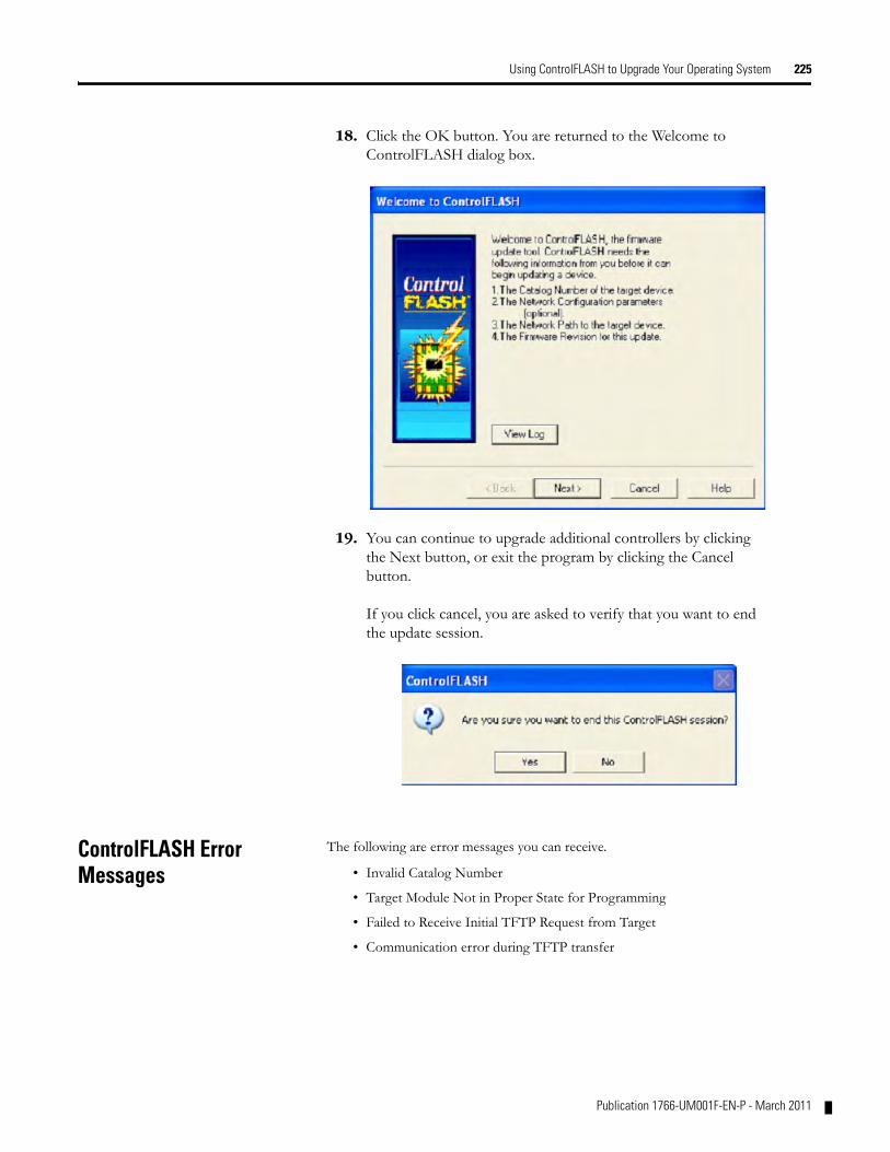
Using ControlFLASH to Upgrade Your Operating System 225
18. Click the OK button. You are returned to the Welcome to ControlFLASH dialog box.
19. You can continue to upgrade additional controllers by clicking the Next button, or exit the program by clicking the Cancel button.
If you click cancel, you are asked to verify that you want to end the update session.
ControlFLASH Error Messages
The following are error messages you can receive.
• Invalid Catalog Number
• Target Module Not in Proper State for Programming
• Failed to Receive Initial TFTP Request from Target
• Communication error during TFTP transfer
Publication 1766-UM001F-EN-P - March 2011
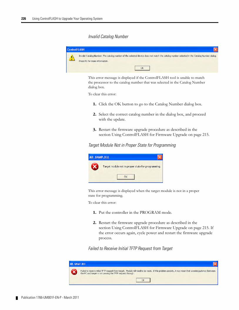
226 Using ControlFLASH to Upgrade Your Operating System
Invalid Catalog Number
This error message is displayed if the ControlFLASH tool is unable to match the processor to the catalog number that was selected in the Catalog Number dialog box.
To clear this error:
1. Click the OK button to go to the Catalog Number dialog box.
2. Select the correct catalog number in the dialog box, and proceed with the update.
3. Restart the firmware upgrade procedure as described in the section Using ControlFLASH for Firmware Upgrade on page 215.
Target Module Not in Proper State for Programming
This error message is displayed when the target module is not in a proper state for programming.
To clear this error:
1. Put the controller in the PROGRAM mode.
2. Restart the firmware upgrade procedure as described in the section Using ControlFLASH for Firmware Upgrade on page 215. If the error occurs again, cycle power and restart the firmware upgrade process.
Failed to Receive Initial TFTP Request from Target
Publication 1766-UM001F-EN-P - March 2011
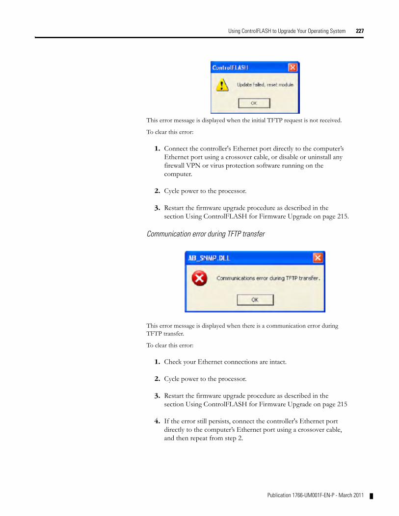
Using ControlFLASH to Upgrade Your Operating System 227
This error message is displayed when the initial TFTP request is not received.
To clear this error:
1. Connect the controller's Ethernet port directly to the computer’s Ethernet port using a crossover cable, or disable or uninstall any firewall VPN or virus protection software running on the computer.
2. Cycle power to the processor.
3. Restart the firmware upgrade procedure as described in the section Using ControlFLASH for Firmware Upgrade on page 215.
Communication error during TFTP transfer
This error message is displayed when there is a communication error during TFTP transfer.
To clear this error:
1. Check your Ethernet connections are intact.
2. Cycle power to the processor.
3. Restart the firmware upgrade procedure as described in the section Using ControlFLASH for Firmware Upgrade on page 215
4. If the error still persists, connect the controller's Ethernet port directly to the computer’s Ethernet port using a crossover cable, and then repeat from step 2.
Publication 1766-UM001F-EN-P - March 2011
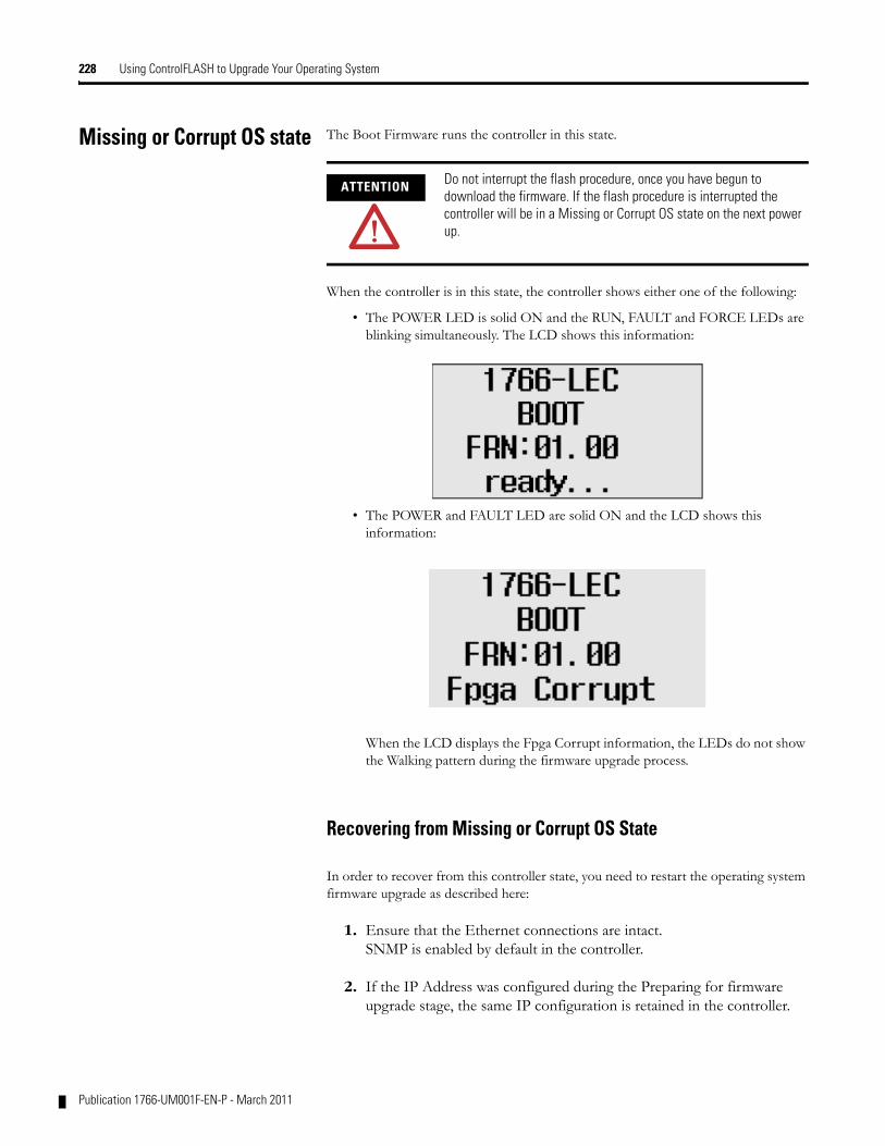
228 Using ControlFLASH to Upgrade Your Operating System
Missing or Corrupt OS state The Boot Firmware runs the controller in this state.
When the controller is in this state, the controller shows either one of the following:
• The POWER LED is solid ON and the RUN, FAULT and FORCE LEDs are blinking simultaneously. The LCD shows this information:
• The POWER and FAULT LED are solid ON and the LCD shows this information:
When the LCD displays the Fpga Corrupt information, the LEDs do not show the Walking pattern during the firmware upgrade process.
Recovering from Missing or Corrupt OS State
In order to recover from this controller state, you need to restart the operating system firmware upgrade as described here:
1. Ensure that the Ethernet connections are intact.SNMP is enabled by default in the controller.
2. If the IP Address was configured during the Preparing for firmware upgrade stage, the same IP configuration is retained in the controller.
ATTENTION Do not interrupt the flash procedure, once you have begun to download the firmware. If the flash procedure is interrupted the controller will be in a Missing or Corrupt OS state on the next power up.
Publication 1766-UM001F-EN-P - March 2011

Using ControlFLASH to Upgrade Your Operating System 229
3. Start the Firmware upgrade as explained in Using ControlFLASH for Firmware Upgrade on page 215.
Publication 1766-UM001F-EN-P - March 2011

230 Using ControlFLASH to Upgrade Your Operating System
Notes:
Publication 1766-UM001F-EN-P - March 2011
Appendix E
Connecting to Networks via RS-232/RS-485 Interface
The following protocols are supported from the RS-232/485 combo communication channel (Channel 0) and the RS-232 communication channel (Channel 2):
• DF1 Full Duplex
• DF1 Half-Duplex Master/Slave
• DF1 Radio Modem
• DH-485
• Modbus RTU Master/Slave
• ASCII
• DNP3 Slave
RS-232 Communication Interface
The communications port on Channel 0 of the MicroLogix 1400 controller utilizes a combined, isolated RS-232/485 interface. RS-232 and RS-485 are Electronics Industries Association (EIA) standards that specify the electrical and mechanical characteristics for serial binary communication. They provide a variety of system configuration possibilities (RS-232 and RS-485 define electrical connection characteristics, not protocols).
The MicroLogix 1400 controller supports an additional, non-isolated RS-232 interface on Channel 2. One of the biggest benefits of an RS-232 interface is that it lets you integrate telephone and radio modems into your control system (using the appropriate DF1 protocol only, not DH-485 protocol), but it is for point-to-point connections only between two devices.
RS-485 Communication Interface
The RS-485 interface supports connection of devices in a multidrop hard-wired configuration using DH-485, DF1-Half Duplex, Modbus, or DNP3 protocols. Also, the RS-485 interface supports connection in a multidrop hard-wired configuration using ASCII protocols.
DF1 Full-Duplex Protocol DF1 Full-Duplex protocol provides a point-to-point connection between two devices. DF1 Full-Duplex protocol combines data transparency (American National Standards Institute ANSI - X3.28-1976 specification subcategory D1) and 2-way simultaneous transmission with embedded responses (subcategory F1).
231 Publication 1766-UM001F-EN-P - March 2011
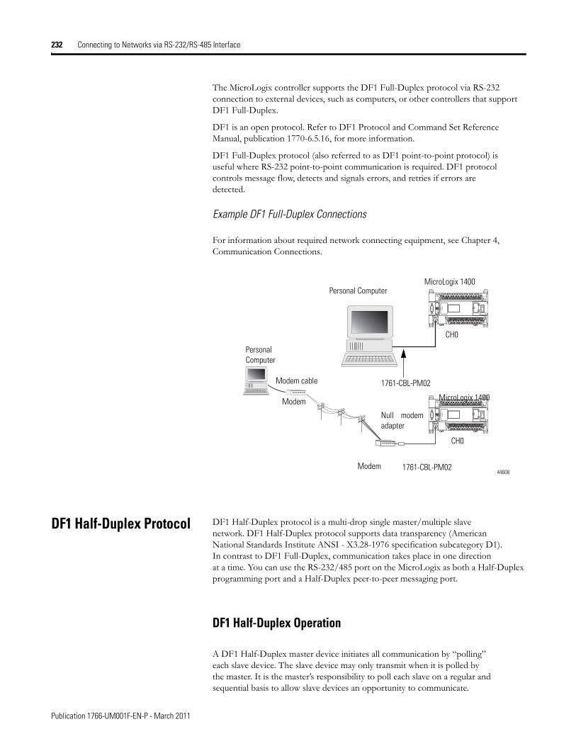
232 Connecting to Networks via RS-232/RS-485 Interface
The MicroLogix controller supports the DF1 Full-Duplex protocol via RS-232 connection to external devices, such as computers, or other controllers that support DF1 Full-Duplex.
DF1 is an open protocol. Refer to DF1 Protocol and Command Set Reference Manual, publication 1770-6.5.16, for more information.
DF1 Full-Duplex protocol (also referred to as DF1 point-to-point protocol) is useful where RS-232 point-to-point communication is required. DF1 protocol controls message flow, detects and signals errors, and retries if errors are detected.
Example DF1 Full-Duplex Connections
For information about required network connecting equipment, see Chapter 4, Communication Connections.
DF1 Half-Duplex Protocol DF1 Half-Duplex protocol is a multi-drop single master/multiple slave network. DF1 Half-Duplex protocol supports data transparency (American National Standards Institute ANSI - X3.28-1976 specification subcategory D1). In contrast to DF1 Full-Duplex, communication takes place in one direction at a time. You can use the RS-232/485 port on the MicroLogix as both a Half-Duplex programming port and a Half-Duplex peer-to-peer messaging port.
DF1 Half-Duplex Operation
A DF1 Half-Duplex master device initiates all communication by “polling” each slave device. The slave device may only transmit when it is polled by the master. It is the master’s responsibility to poll each slave on a regular and sequential basis to allow slave devices an opportunity to communicate.
Personal Computer
CH0
MicroLogix 1400
MicroLogix 1400
1761-CBL-PM02
Personal Computer
Modem cable
Modem
Modem 1761-CBL-PM02
Null modemadapter
CH0
44608
Publication 1766-UM001F-EN-P - March 2011
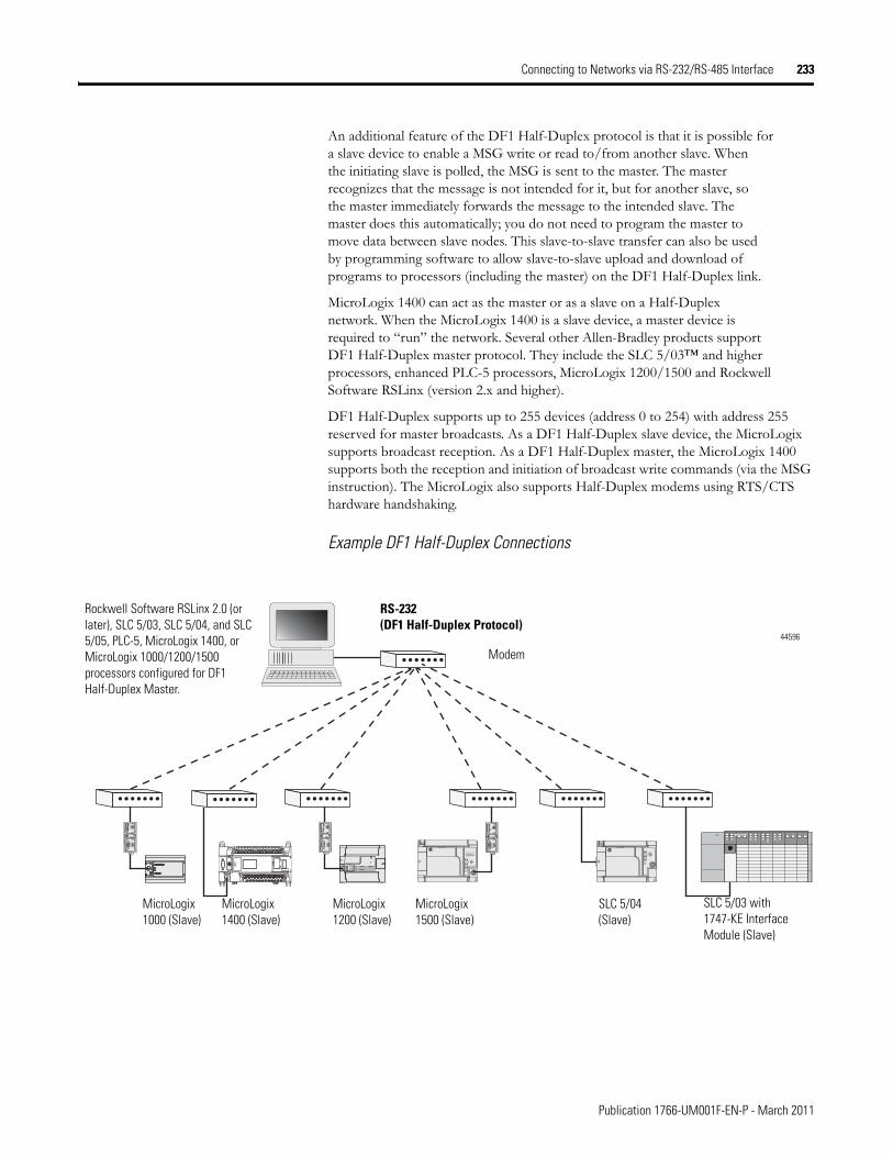
Connecting to Networks via RS-232/RS-485 Interface 233
An additional feature of the DF1 Half-Duplex protocol is that it is possible for a slave device to enable a MSG write or read to/from another slave. When the initiating slave is polled, the MSG is sent to the master. The master recognizes that the message is not intended for it, but for another slave, so the master immediately forwards the message to the intended slave. The master does this automatically; you do not need to program the master to move data between slave nodes. This slave-to-slave transfer can also be used by programming software to allow slave-to-slave upload and download of programs to processors (including the master) on the DF1 Half-Duplex link.
MicroLogix 1400 can act as the master or as a slave on a Half-Duplex network. When the MicroLogix 1400 is a slave device, a master device is required to “run” the network. Several other Allen-Bradley products support DF1 Half-Duplex master protocol. They include the SLC 5/03™ and higher processors, enhanced PLC-5 processors, MicroLogix 1200/1500 and Rockwell Software RSLinx (version 2.x and higher).
DF1 Half-Duplex supports up to 255 devices (address 0 to 254) with address 255 reserved for master broadcasts. As a DF1 Half-Duplex slave device, the MicroLogix supports broadcast reception. As a DF1 Half-Duplex master, the MicroLogix 1400 supports both the reception and initiation of broadcast write commands (via the MSG instruction). The MicroLogix also supports Half-Duplex modems using RTS/CTS hardware handshaking.
Example DF1 Half-Duplex Connections
TERM
A
B
COM
SHLD
CHS GND
TX
TX PWR
TX
DC SOURCE CABLE
EXTERNAL
TERM
A
B
COM
SHLD
CHS GND
TX
TX PWR
TX
DC SOURCE CABLE
EXTERNAL
TERM
A
B
COM
SHLD
CHS GND
TX
TX PWR
TX
DC SOURCE CABLE
EXTERNAL
Rockwell Software RSLinx 2.0 (or later), SLC 5/03, SLC 5/04, and SLC 5/05, PLC-5, MicroLogix 1400, or MicroLogix 1000/1200/1500 processors configured for DF1 Half-Duplex Master.
RS-232 (DF1 Half-Duplex Protocol)
MicroLogix1500 (Slave)
SLC 5/04 (Slave)
MicroLogix1000 (Slave)
SLC 5/03 with 1747-KE Interface Module (Slave)
MicroLogix1200 (Slave)
Modem
MicroLogix1400 (Slave)
44596
Publication 1766-UM001F-EN-P - March 2011
234 Connecting to Networks via RS-232/RS-485 Interface
Considerations When Communicating as a DF1 Slave on a Multi-drop Link
When communication is between either your programming software and a MicroLogix Programmable Controller or between two MicroLogix 1400 Programmable Controllers via slave-to-slave communication on a larger multi-drop link, the devices depend on a DF1 Half-Duplex Master to give each of them access in a timely manner. As the number of slave devices increase, the time between when slave devices are polled also increases. This increase in time may also be large if you are using low baud rates. As these time periods grow, you may need to increase the poll timeout and reply timeout values for slave devices.
Using Modems with MicroLogix Programmable Controllers
The types of modems you can use with MicroLogix controllers include the following:
• dial-up phone modems.A MicroLogix controller, on the receiving end of the dial-up connection, can be configured for DF1 Full-Duplex protocol with or without handshaking. The modem connected to the MicroLogix controller should support auto-answer. The MicroLogix 1400 supports ASCII out communications. Therefore, it can cause a modem to initiate or disconnect a phone call.
• leased-line modems.Leased-line modems are used with dedicated phone lines that are typically leased from the local phone company. The dedicated lines may be in a point-to-point topology supporting Full-Duplex communications between two modems or in a multi-drop topology supporting Half-Duplex communications between three or more modems.
IMPORTANT If a program download is started when using DF1 Half-Duplex, but then is interrupted due to electromagnetic interference or other events, discontinue communications to the controller for the ownership timeout period and then restart the program download. The ownership timeout period is 60 seconds. After the timeout, you can re-establish communications with the processor and try the program download again. The only other way to remove program ownership is to cycle power on the processor.
Publication 1766-UM001F-EN-P - March 2011
Connecting to Networks via RS-232/RS-485 Interface 235
• radio modems.Radio modems may be implemented in a point-to-point topology supporting either Half-Duplex or Full-Duplex communications, or in a multi-drop topology supporting Half-Duplex communications between three or more modems. MicroLogix 1400 also supports DF1 Radio Modem protocol.
• line drivers.Line drivers, also called short-haul modems, do not actually modulate the serial data, but rather condition the electrical signals to operate reliably over long transmission distances (up to several miles). Line drivers are available in Full-Duplex and Half-Duplex models. Allen-Bradley’s AIC+ Advanced Interface Converter is a Half-Duplex line driver that converts an RS-232 electrical signal into an RS-485 electrical signal, increasing the signal transmission distance from 50 to 4000 feet (8000 feet when bridged).
For point-to-point Full-Duplex modem connections that do not require any modem handshaking signals to operate, use DF1 Full-Duplex protocol with no handshaking. For point-to-point Full-Duplex modem connections that require RTS/CTS handshaking, use DF1 Full-Duplex protocol with handshaking.
For radio modem connections, use DF1 Radio Modem protocol, especially if store and forward capability is required.
For general multi-drop modem connections, or for point-to-point modem connections that require RTS/CTS handshaking, use DF1 Half-Duplex slave protocol. In this case, one (and only one) of the other devices must be configured for DF1 Half-Duplex master protocol.
DH-485 Communication Protocol
The DH-485 protocol defines the communication between multiple devices that coexist on a single pair of wires. DH-485 protocol uses RS-485 Half-Duplex as its physical interface. (RS-485 is a definition of electrical
IMPORTANT Never attempt to use DH-485 protocol through modems under any circumstance.
TIP All MicroLogix controllers support RTS/CTS modem handshaking when configured for DF1 Full-Duplex protocol with the control line parameter set to Full-Duplex Modem Handshaking or DF1 Half-Duplex slave protocol with the control line parameter set to “Half-Duplex Modem”. MicroLogix 1400 controllers also support DCD (Data Carrier Detect) line for DF1 Radio Modem protocol. For other protocols, you can only access the DCD signal from your ladder logic. No other modem handshaking lines (such as Data Set Ready and Data Terminal Ready) are supported by MicroLogix 1400 controller.
Publication 1766-UM001F-EN-P - March 2011
236 Connecting to Networks via RS-232/RS-485 Interface
characteristics; it is not a protocol.) RS-485 uses devices that are capable of co-existing on a common data circuit, thus allowing data to be easily shared between devices.
The DH-485 network offers:
• interconnection of 32 devices
• multi-master (peer-to-peer) capability
• token passing access control
• the ability to add or remove nodes without disrupting the network
• maximum network segment of 1,219 m (4,000 ft.)
The DH-485 protocol supports two classes of devices: initiators and responders. All initiators on the network get a chance to initiate message transfers. To determine which initiator has the right to transmit, a token passing algorithm is used.
Control of message transfers on the DH-485 network is performed by rotating the token along the nodes on the network. A node holding the token can send a message onto the network. Each node is allowed a fixed number of transmissions (based on the Token Hold Factor) each time it receives the token. After a node sends a message, it passes the token to the next device.
The allowable range of node addresses is 1…31. There must be at least one initiator on the network (such as a MicroLogix controller, or an SLC 5/02 or later processor).
DH-485 Configuration Parameters
When MicroLogix communications are configured for DH-485, the following parameters can be changed:
See Software Considerations on page 239 for tips on setting the parameters listed above.
DF1 Full-Duplex Configuration Parameters
Parameter Options
Baud Rate 9600, 19.2K
Node Address 1…31 decimal
Token Hold Factor 1…4
Publication 1766-UM001F-EN-P - March 2011
Connecting to Networks via RS-232/RS-485 Interface 237
Devices that use the DH-485 Network
In addition to the MicroLogix controllers, the devices shown in the following table also support the DH-485 network .
Important DH-485 Network Planning Considerations
Carefully plan your network configuration before installing any hardware. Some of the factors that can affect system performance are:
• amount of electrical noise, temperature, and humidity in the network environment.
• number of devices on the network.
• connection and grounding quality in installation.
• amount of communication traffic on the network.
• type of process being controlled.
Allen-Bradley Devices that Support DH-485 Communication
Catalog Number
Description Installation Function Publication
Bulletin 1761 Controllers
MicroLogix 1000 Series C or later
These controllers support DH-485 communications. 1761-6.3
Bulletin 1762 MicroLogix 1200 Series A or later
These controllers support DH-485 communications. 1762-UM001
Bulletin 1763 MicroLogix 1100 Series A or later
These controllers support DH-485 communications. 1763-UM001
Bulletin 1764 MicroLogix 1500 Series A or later
These controllers support DH-485 communications. 1764-UM001
Bulletin 1747 Processors
SLC 500 Processors
SLC Chassis These processors support a variety of I/O requirements and functionality.
1747-UM011
1746-BAS BASIC Module SLC Chassis Provides an interface for SLC 500 devices to foreign devices. Program in BASIC to interface the 3 channels (2 RS232 and 1 DH-485) to printers, modems, or the DH-485 network for data collection.
1746-UM004 1746-PM001 1746-RM001
2760-RB Flexible Interface Module
(1771) PLC Chassis
Provides an interface for SLC 500 (using protocol cartridge 2760-SFC3) to other A-B PLCs and devices. Three configurable channels are available to interface with Bar Code, Vision, RF, Dataliner™, and PLC systems.
1747-6.12
2760-ND001
1784-PKTX, -PKTXD
PC DH-485 IM PCI Computer Bus
Provides DH-485 using RSLinx. 1784-6.5.22
1784-PCMK PCMCIA IM PCMCIA slot in computer
Provides DH-485 using RSLinx. 1784-UM519
2711-K5A2, -B5A2, -K5A5, -B5A5, -K5A1, -B5A1, -K9A2, -T9A2, -K9A5, -T9A5, -K9A1, and -T9A1
PanelView 550 and PanelView 900 Operator Terminals
Panel Mount Provides electronic operator interface for SLC 500 processors. 2711-UM014
Publication 1766-UM001F-EN-P - March 2011
238 Connecting to Networks via RS-232/RS-485 Interface
• network configuration.
The major hardware and software issues you need to resolve before installing a network are discussed in the following sections.
Hardware Considerations
You need to decide the length of the communication cable, where you route it, and how to protect it from the environment where it will be installed.
When the communication cable is installed, you need to know how many devices are to be connected during installation and how many devices will be added in the future. The following sections help you understand and plan the network.
Number of Devices and Length of Communication Cable
The maximum length of the communication cable is 1219 m (4000 ft). This is the total cable distance from the first node to the last node in a segment. However, two segments can be used to extend the DH-485 network to 2438 m (8000 ft.). For additional information on connections using the AIC+, refer to the Advanced Interface Converter (AIC+) User Manual, publication 1761-6.4.
Planning Cable Routes
Follow these guidelines to help protect the communication cable from electrical interference:
• Keep the communication cable at least 1.52 m (5 ft.) from any electric motors, transformers, rectifiers, generators, arc welders, induction furnaces, or sources of microwave radiation.
• If you must run the cable across power feed lines, run the cable at right angles to the lines.
• If you do not run the cable through a contiguous metallic wireway or conduit, keep the communication cable at least 0.15 m (6 in.) from AC power lines of less than 20 A, 0.30 m (1 ft.) from lines greater than 20 A, but only up to 100K VA, and 0.60 m (2 ft.) from lines of 100 K VA or more.
• If you run the cable through a contiguous metallic wireway or conduit, keep the communication cable at least 0.08 m (3 in.) from AC power lines of less than 20 A, 0.15 m (6 in.) from lines greater than 20 A, but only up to 100 K VA, and 0.30 m (1 ft.) from lines of 100 K VA or more.
Running the communication cable through conduit provides extra protection from physical damage and electrical
Publication 1766-UM001F-EN-P - March 2011
Connecting to Networks via RS-232/RS-485 Interface 239
interference. If you route the cable through conduit, follow these additional recommendations:
– Use ferromagnetic conduit near critical sources of electrical interference. You can use aluminum conduit in non-critical areas.
– Use plastic connectors to couple between aluminum and ferromagnetic conduit. Make an electrical connection around the plastic connector (use pipe clamps and the heavy gauge wire or wire braid) to hold both sections at the same potential.
– Ground the entire length of conduit by attaching it to the building earth ground.
– Do not let the conduit touch the plug on the cable.
– Arrange the cables loosely within the conduit. The conduit should contain only serial communication cables.
– Install the conduit so that it meets all applicable codes and environmental specifications.
For more information on planning cable routes, see Industrial Automation Wiring and Grounding Guidelines, publication 1770-4.1.
Software Considerations
Software considerations include the configuration of the network and the parameters that can be set to the specific requirements of the network. The following are major configuration factors that have a significant effect on network performance:
• number of nodes on the network
• addresses of those nodes
• baud rate
The following sections explain network considerations and describe ways to select parameters for optimum network performance (speed). See your programming software’s user manual for more information.
Number of Nodes
The number of nodes on the network directly affects the data transfer time between nodes. Unnecessary nodes (such as a second programming terminal that is not being used) slow the data transfer rate. The maximum number of nodes on the network is 32.
Publication 1766-UM001F-EN-P - March 2011
240 Connecting to Networks via RS-232/RS-485 Interface
Setting Node Addresses
The best network performance occurs when node addresses are assigned in sequential order. Initiators, such as personal computers, should be assigned the lowest numbered addresses to minimize the time required to initialize the network. The valid range for the MicroLogix controllers is 1...31 (controllers cannot be node 0). The default setting is 1. The node address is stored in the controller Communications Status file (CS0:5/0 to CS0:5/7).
Setting Controller Baud Rate
The best network performance occurs at the highest baud rate, which is 19,200. This is the default baud rate for a MicroLogix device on the DH-485 network. All devices must be at the same baud rate. This rate is stored in the controller Communications Status file (CS0:5/8 to CS0:5/15).
Setting Maximum Node Address
Once you have an established network set up and are confident that you will not be adding more devices, you may enhance performance by adjusting the maximum node address of your controllers. It should be set to the highest node address being used.
MicroLogix Remote Packet Support
MicroLogix controllers can respond and initiate with communications (or commands) that do not originate on the local DH-485 network. This is useful in installations where communication is needed between DH-485 and DH+ networks.
The example below shows how to send messages from a device on the DH+ network to a MicroLogix controller on the DH-485 network. This method uses an SLC 5/04 processor as the bridge connection.
When using this method (as shown in the illustration below):
• PLC-5 devices can send read and write commands to MicroLogix controllers.
• MicroLogix controllers can respond to MSG instructions received.
• The MicroLogix controllers can initiate MSG instructions to devices on the DH+ network.
• PC can send read and write commands to MicroLogix controllers.
• PC can do remote programming of MicroLogix controllers.
IMPORTANT All devices should be set to the same maximum node address.
Publication 1766-UM001F-EN-P - March 2011
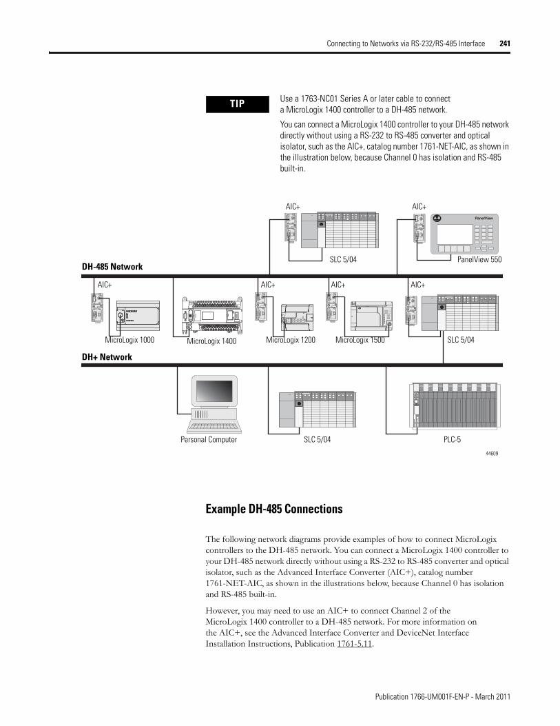
Connecting to Networks via RS-232/RS-485 Interface 241
Example DH-485 Connections
The following network diagrams provide examples of how to connect MicroLogix controllers to the DH-485 network. You can connect a MicroLogix 1400 controller to your DH-485 network directly without using a RS-232 to RS-485 converter and optical isolator, such as the Advanced Interface Converter (AIC+), catalog number 1761-NET-AIC, as shown in the illustrations below, because Channel 0 has isolation and RS-485 built-in.
However, you may need to use an AIC+ to connect Channel 2 of the MicroLogix 1400 controller to a DH-485 network. For more information on the AIC+, see the Advanced Interface Converter and DeviceNet Interface Installation Instructions, Publication 1761-5.11.
TIP Use a 1763-NC01 Series A or later cable to connect a MicroLogix 1400 controller to a DH-485 network.
You can connect a MicroLogix 1400 controller to your DH-485 network directly without using a RS-232 to RS-485 converter and optical isolator, such as the AIC+, catalog number 1761-NET-AIC, as shown in the illustration below, because Channel 0 has isolation and RS-485 built-in.
A-B PanelViewTERM
A
B
COM
SHLD
CHS GND
TX
TX PWR
TX
DC SOURCE CABLE
EXTERNAL
TERM
A
B
COM
SHLD
CHS GND
TX
TX PWR
TX
DC SOURCE CABLE
EXTERNAL
TERM
A
B
COM
SHLD
CHS GND
TX
TX PWR
TX
DC SOURCE CABLE
EXTERNAL
TERM
A
B
COM
SHLD
CHS GND
TX
TX PWR
TX
DC SOURCE CABLE
EXTERNAL
TERM
A
B
COM
SHLD
CHS GND
TX
TX PWR
TX
DC SOURCE CABLE
EXTERNAL
TERM
A
B
COM
SHLD
CHS GND
TX
TX PWR
TX
DC SOURCE CABLE
EXTERNAL
AIC+ AIC+ AIC+
AIC+
DH-485 NetworkSLC 5/04 PanelView 550
MicroLogix 1500MicroLogix 1000 MicroLogix 1200 SLC 5/04
AIC+
AIC+
SLC 5/04 PLC-5
DH+ Network
Personal Computer
MicroLogix 1400
44609
Publication 1766-UM001F-EN-P - March 2011
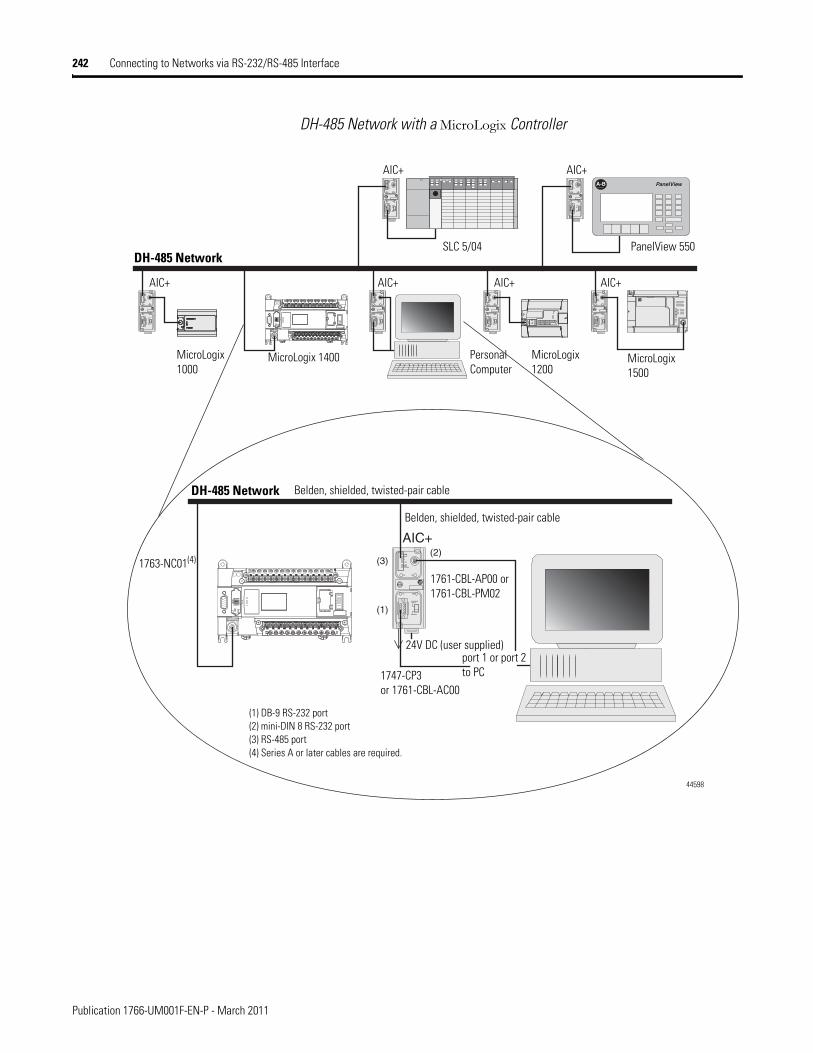
242 Connecting to Networks via RS-232/RS-485 Interface
DH-485 Network with a MicroLogix Controller
A-B PanelViewTERM
A
B
COM
SHLD
CHS GND
TX
TX PWR
TX
DC SOURCE CABLE
EXTERNAL
TERM
A
B
COM
SHLD
CHS GND
TX
TX PWR
TX
DC SOURCE CABLE
EXTERNAL
TERM
A
B
COM
SHLD
CHS GND
TX
TX PWR
TX
DC SOURCE CABLE
EXTERNAL
TERM
A
B
COM
SHLD
CHS GND
TX
TX PWR
TX
DC SOURCE CABLE
EXTERNAL
TERM
A
B
COM
SHLD
CHS GND
TX
TX PWR
TX
DC SOURCE CABLE
EXTERNAL
TERM
A
B
COM
SHLD
CHS GND
TX
TX PWR
TX
DC SOURCE CABLE
EXTERNAL
(2)AIC+
(1)
(3)TERM
A
B
COM
SHLD
CHS GND
TX
TX PWR
TX
DC SOURCE CABLE
EXTERNAL
AIC+ AIC+ AIC+
AIC+
DH-485 NetworkSLC 5/04 PanelView 550
MicroLogix 1500
MicroLogix 1000
MicroLogix 1200
Personal Computer
AIC+
AIC+
MicroLogix 1400
DH-485 Network
1763-NC01(4)
Belden, shielded, twisted-pair cable
Belden, shielded, twisted-pair cable
1761-CBL-AP00 or 1761-CBL-PM02
1747-CP3or 1761-CBL-AC00
port 1 or port 2 to PC
24V DC (user supplied)
(1) DB-9 RS-232 port(2) mini-DIN 8 RS-232 port(3) RS-485 port(4) Series A or later cables are required.
44598
Publication 1766-UM001F-EN-P - March 2011
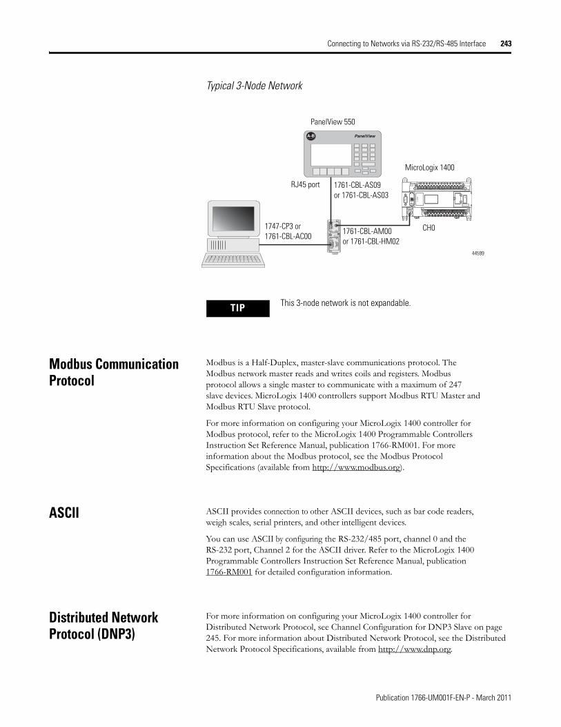
Connecting to Networks via RS-232/RS-485 Interface 243
Typical 3-Node Network
Modbus Communication Protocol
Modbus is a Half-Duplex, master-slave communications protocol. The Modbus network master reads and writes coils and registers. Modbus protocol allows a single master to communicate with a maximum of 247 slave devices. MicroLogix 1400 controllers support Modbus RTU Master and Modbus RTU Slave protocol.
For more information on configuring your MicroLogix 1400 controller for Modbus protocol, refer to the MicroLogix 1400 Programmable Controllers Instruction Set Reference Manual, publication 1766-RM001. For more information about the Modbus protocol, see the Modbus Protocol Specifications (available from http://www.modbus.org).
ASCII ASCII provides connection to other ASCII devices, such as bar code readers, weigh scales, serial printers, and other intelligent devices.
You can use ASCII by configuring the RS-232/485 port, channel 0 and the RS-232 port, Channel 2 for the ASCII driver. Refer to the MicroLogix 1400 Programmable Controllers Instruction Set Reference Manual, publication 1766-RM001 for detailed configuration information.
Distributed Network Protocol (DNP3)
For more information on configuring your MicroLogix 1400 controller for Distributed Network Protocol, see Channel Configuration for DNP3 Slave on page 245. For more information about Distributed Network Protocol, see the Distributed Network Protocol Specifications, available from http://www.dnp.org.
TERM
A
B
COM
SHLD
CHS GND
TX
TX PWR
TX
DC SOURCE CABLE
EXTERNAL
A-B PanelView
PanelView 550
MicroLogix 1400
1761-CBL-AM00or 1761-CBL-HM02
1747-CP3 or 1761-CBL-AC00
RJ45 port 1761-CBL-AS09or 1761-CBL-AS03
CH0
44599
TIP This 3-node network is not expandable.
Publication 1766-UM001F-EN-P - March 2011

244 Connecting to Networks via RS-232/RS-485 Interface
Notes:
Publication 1766-UM001F-EN-P - March 2011
Appendix F
Micrologix 1400 Distributed Network Protocol (DNP3)
This appendix:
• describes the MicroLogix 1400 Distributed Network Protocol (DNP3).
• describes the procedures used to program and troubleshoot DNP3 protocol in the controller.
• gives an overview of the DNP3 implementation in the controller
• shows application examples of DNP3 applications.
Channel Configuration for DNP3 Slave
The default communication protocol for the serial ports Channel 0 and Channel 2 in the MicroLogix 1400 is DF1 Full-Duplex. To communicate with DNP3 protocol, the channel must be configured to DNP3 protocol.
The default communication protocol for the Ethernet Channel 1 in the MicroLogix 1400 is Ethernet/IP. To communicate with DNP3 over IP protocol in the MicroLogix 1400 Series B controller, the channel must be configured to use the DNP3 protocol.
The MicroLogix 1400 Series A controller supports DNP3 protocol via Channel 0 and/or Channel 2 Serial ports.
The MicroLogix 1400 Series B controller also supports DNP3 over IP protocol via Channel 1 Ethernet port.
To program the MicroLogix 1400 controller, use RSLogix 500/RSLogix Micro software, version 8.10.00 or later for Series A controller and version 8.30.00 or later for Series B controller.
245 Publication 1766-UM001F-EN-P - March 2011
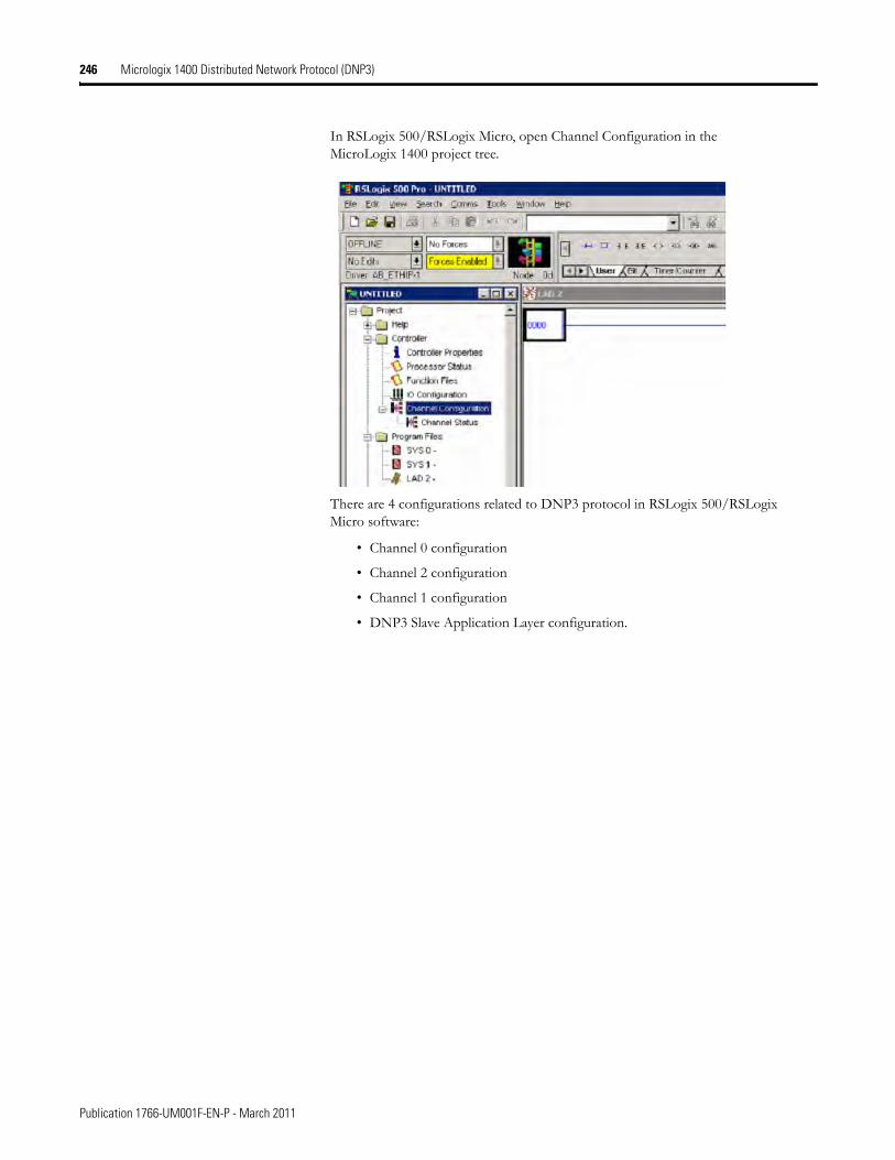
246 Micrologix 1400 Distributed Network Protocol (DNP3)
In RSLogix 500/RSLogix Micro, open Channel Configuration in the MicroLogix 1400 project tree.
There are 4 configurations related to DNP3 protocol in RSLogix 500/RSLogix Micro software:
• Channel 0 configuration
• Channel 2 configuration
• Channel 1 configuration
• DNP3 Slave Application Layer configuration.
Publication 1766-UM001F-EN-P - March 2011
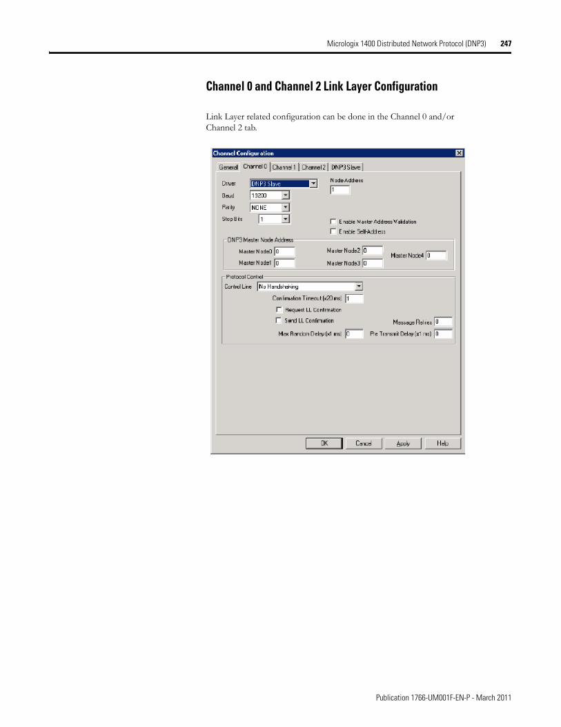
Micrologix 1400 Distributed Network Protocol (DNP3) 247
Channel 0 and Channel 2 Link Layer Configuration
Link Layer related configuration can be done in the Channel 0 and/or Channel 2 tab.
Publication 1766-UM001F-EN-P - March 2011
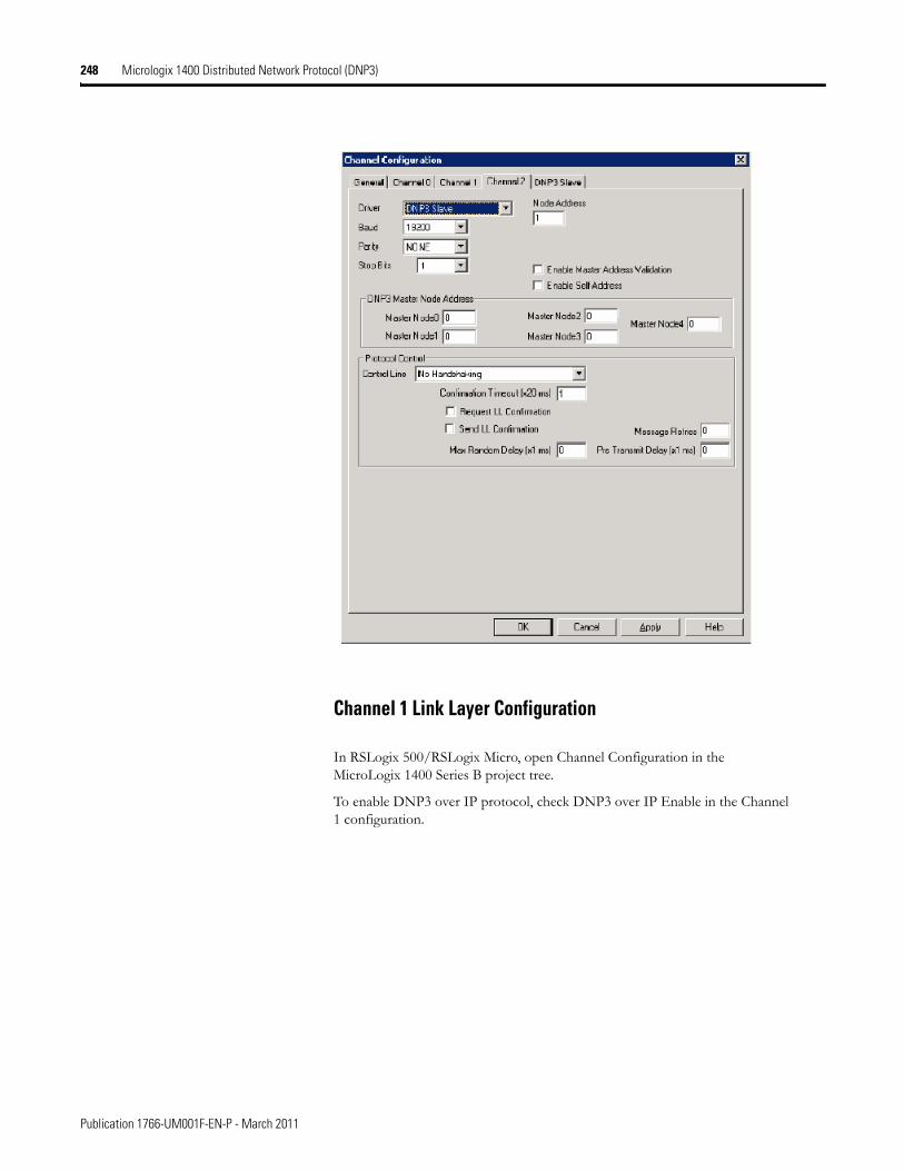
248 Micrologix 1400 Distributed Network Protocol (DNP3)
Channel 1 Link Layer Configuration
In RSLogix 500/RSLogix Micro, open Channel Configuration in the MicroLogix 1400 Series B project tree.
To enable DNP3 over IP protocol, check DNP3 over IP Enable in the Channel 1 configuration.
Publication 1766-UM001F-EN-P - March 2011
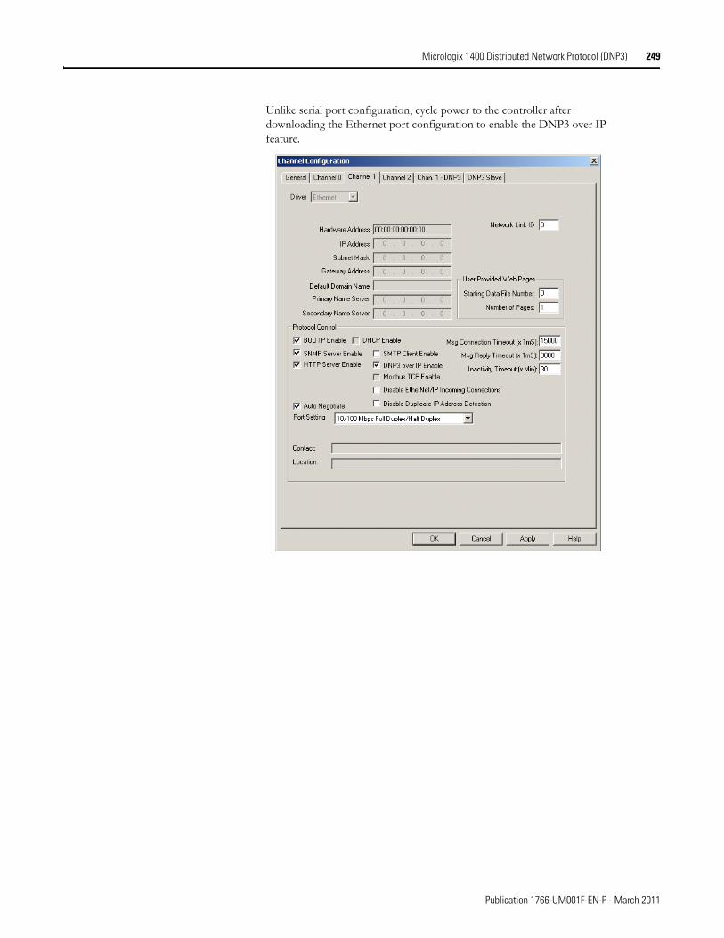
Micrologix 1400 Distributed Network Protocol (DNP3) 249
Unlike serial port configuration, cycle power to the controller after downloading the Ethernet port configuration to enable the DNP3 over IP feature.
Publication 1766-UM001F-EN-P - March 2011
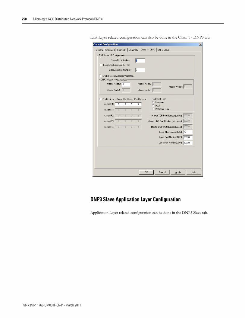
250 Micrologix 1400 Distributed Network Protocol (DNP3)
Link Layer related configuration can also be done in the Chan. 1 - DNP3 tab.
DNP3 Slave Application Layer Configuration
Application Layer related configuration can be done in the DNP3 Slave tab.
Publication 1766-UM001F-EN-P - March 2011
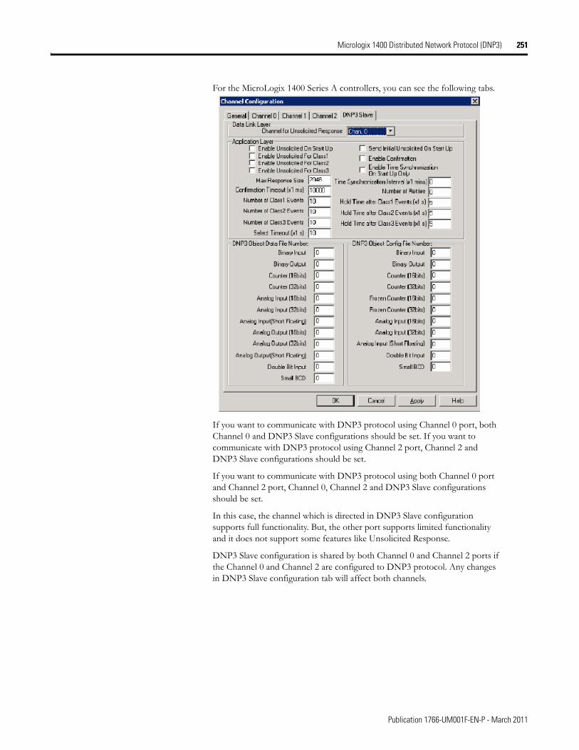
Micrologix 1400 Distributed Network Protocol (DNP3) 251
For the MicroLogix 1400 Series A controllers, you can see the following tabs.
If you want to communicate with DNP3 protocol using Channel 0 port, both Channel 0 and DNP3 Slave configurations should be set. If you want to communicate with DNP3 protocol using Channel 2 port, Channel 2 and DNP3 Slave configurations should be set.
If you want to communicate with DNP3 protocol using both Channel 0 port and Channel 2 port, Channel 0, Channel 2 and DNP3 Slave configurations should be set.
In this case, the channel which is directed in DNP3 Slave configuration supports full functionality. But, the other port supports limited functionality and it does not support some features like Unsolicited Response.
DNP3 Slave configuration is shared by both Channel 0 and Channel 2 ports if the Channel 0 and Channel 2 are configured to DNP3 protocol. Any changes in DNP3 Slave configuration tab will affect both channels.
Publication 1766-UM001F-EN-P - March 2011
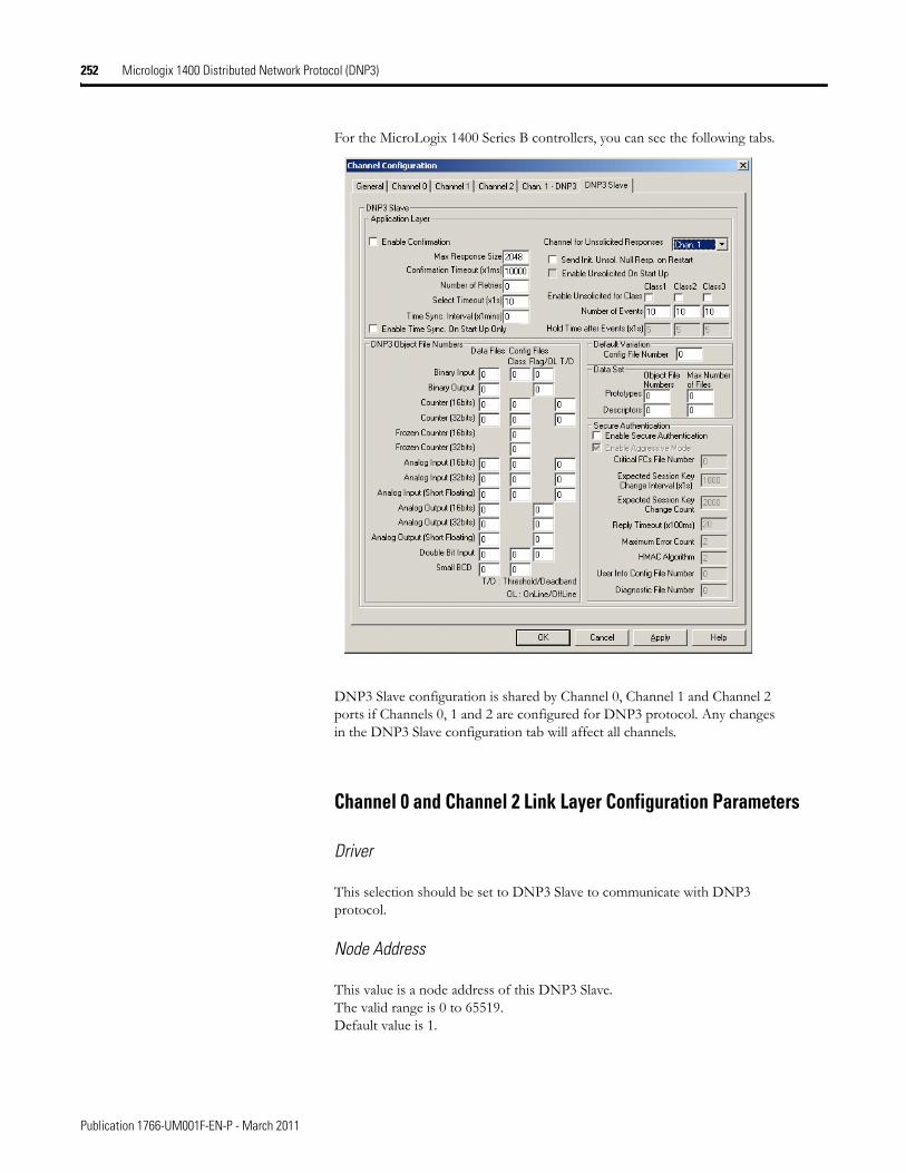
252 Micrologix 1400 Distributed Network Protocol (DNP3)
For the MicroLogix 1400 Series B controllers, you can see the following tabs.
DNP3 Slave configuration is shared by Channel 0, Channel 1 and Channel 2 ports if Channels 0, 1 and 2 are configured for DNP3 protocol. Any changes in the DNP3 Slave configuration tab will affect all channels.
Channel 0 and Channel 2 Link Layer Configuration Parameters
Driver
This selection should be set to DNP3 Slave to communicate with DNP3 protocol.
Node Address
This value is a node address of this DNP3 Slave.The valid range is 0 to 65519. Default value is 1.
Publication 1766-UM001F-EN-P - March 2011
Micrologix 1400 Distributed Network Protocol (DNP3) 253
Baud
The selections can be "38.4 K", "19200", "9600", "4800", "2400", "1200", "600", and "300". Default selection is "19200".
Parity
The selections can be "NONE", "EVEN", and "ODD". Default selection is "NONE".
Stop Bits
The selections can be "1", "1.5", and "2". Default selection is "1".
Enable Master Address Validation
Valid selections are Enabled(Checked) and Disabled(Unchecked). Default value is Disabled (Unchecked).
When the selection is Disabled(Unchecked), the MicroLogix 1400 accepts the requests from any DNP3 Master.
When the selection is Enabled(Checked), the MicroLogix 1400 accepts the requests only from the DNP3 Master which is configured in the Master Node0 to Master Node4. The maximum number of Master Node Addresses for the Master Address Validation is 5.
Enable Self-Address
Valid selections are Enabled(Checked) and Disabled(Unchecked). Default value is Disabled (Unchecked).
When this bit is Disabled(Unchecked), any packets which contain the destination address 65532(FFFCh) are ignored.
When this bit is Enabled(Checked), any packets which contain the destination address 65532(FFFCh) are accepted and processed.
Master Node0
This value is used to:
• validate the Master node address when the Enable Master Address Validation is Enabled (Checked)
• send Unsolicited Response when Unsolicited Response functionality is enabled. An Unsolicited Response is sent out to the DNP3 Master having this address.
The valid range is 0 to 65519. Default value is 0.
Publication 1766-UM001F-EN-P - March 2011
254 Micrologix 1400 Distributed Network Protocol (DNP3)
Master Node1, Master Node2, Master Node3, Master Node4
The valid range is 0 to 65519. Default value is 0.
This value is used to check validation for Master node address when Enable Master Address Validation is Enabled (Checked).
Control
For Channel 0, the selections can be No Handshaking, Half Duplex Modem(CTS/RTS handshaking) and No Handshaking (485 Network). Default selection is No Handshaking.
For Channel 2, the selections can be No Handshaking, and Half Duplex Modem(CTS/RTS handshaking). Default selection is No Handshaking.
When the MicroLogix 1400 is connected to DNP3 Master using RS-232 line directly, you must select No Handshaking. If you want to use the Modem line in a half duplex network, you must select Half Duplex Modem(CTS/RTS handshaking). If the MicroLogix 1400 is connected to an RS-485 network and a 1763-NC01 cable is used, you must select No Handshaking (485 Network).
If you want to send an ASCII string via a serial channel which is configured to DNP3 Slave protocol, use AWA and AWT instructions to control the Modem.
For Cabling and Connections, see Communication Connections on page 71.
For AWA and AWT instructions, refer to the MicroLogix 1400 Programmable Controllers Instruction Set Reference Manual, 1766-RM001.
Request LL Confirmation
Valid selections are Enabled (Checked) and Disabled (Unchecked). Default value is Disabled (Unchecked).
When the selection is Disabled (Unchecked), Primary Frames from the MicroLogix 1400 are sent out with the function code FC_UNCONFIRMED_USER_DATA (4).
When the selection is Enabled (Checked), Primary Frames from the MicroLogix 1400 are sent out with the function code FC_CONFIRMED_USER_DATA (3). In this case, the MicroLogix 1400 waits for the confirmation and may retry the Frame if it did not receive the confirmation from DNP3 Master within the time Confirmation Timeout (x1 ms).
Send LL Confirmation
Valid selections are Enabled (Checked) and Disabled (Unchecked). Default value is Disabled (Unchecked).
When the selection is Disabled (Unchecked), the optional Secondary Frame is not sent out with the function code FC_NACK (1) or FC_NOT_SUPPORTED (15).
Publication 1766-UM001F-EN-P - March 2011
Micrologix 1400 Distributed Network Protocol (DNP3) 255
When the selection is Enabled (Checked), the optional Secondary Frame is sent out with the function code FC_NACK (1) or FC_NOT_SUPPORTED (15).
Confirmation Timeout (x20 ms)
When Request LL Confirmation is enabled, the MicroLogix 1400 waits to receive a confirmation frame until this timeout has expired.
The valid range is 1…65535. Default value is 1.
Message Retries
When Confirmation Timeout (x1 ms) has expired and this parameter was non-zero value, the MicroLogix 1400 tries to send retry packets.
The valid range is 0…255. Default value is 0.
Pre Transmit Delay (x1 ms)
The MicroLogix 1400 waits for the specified time before sending the packet.
The valid range is 0…65535. Default value is 0.
RTS Off Delay (x20 ms)
When the Control is set at Half Duplex Modem(CTS/RTS handshaking), this feature is enabled. This specifies a time delay between the end of a transmission and dropping of the RTS signal.
The valid range is 0…65535. Default value is 0.
RTS Send Delay (x20 ms)
When the Control is set at Half Duplex Modem(CTS/RTS handshaking), this entry is enabled. This specifies a time delay between the raising of the RTS and the initiation of a transmission.
The valid range is 0…65535. Default value is 0.
Max Random Delay (x1 ms)
This parameter is used with Pre Transmit Delay (x1 ms) for Collision Avoidance on RS-485 network. For more details, see Collision Avoidance on page 334.
The valid range is 0…65535. Default value is 0.
Channel 1(Ethernet) Link Layer Configuration Parameters
This section is only applicable to MicroLogix 1400 Series B controllers.
The DNP3 over IP subsystem in the MicroLogix 1400 supports Listening End Point, TCP Dual End Point and Datagram End Point type.
Publication 1766-UM001F-EN-P - March 2011
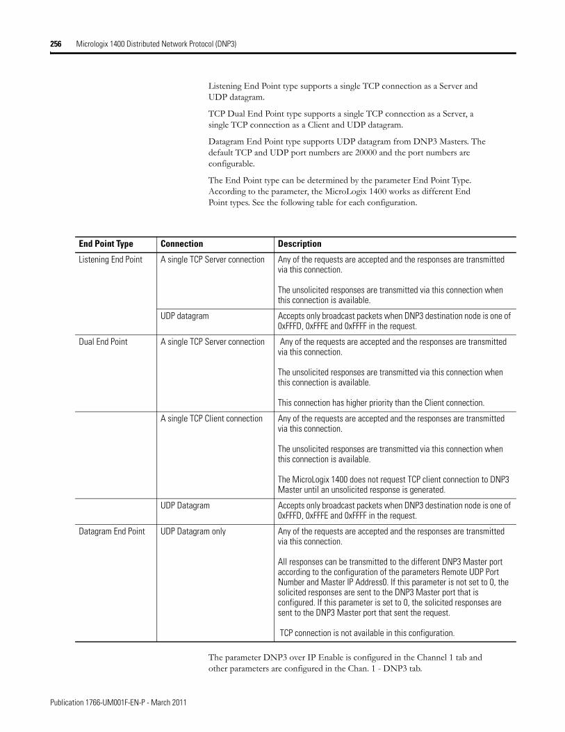
256 Micrologix 1400 Distributed Network Protocol (DNP3)
Listening End Point type supports a single TCP connection as a Server and UDP datagram.
TCP Dual End Point type supports a single TCP connection as a Server, a single TCP connection as a Client and UDP datagram.
Datagram End Point type supports UDP datagram from DNP3 Masters. The default TCP and UDP port numbers are 20000 and the port numbers are configurable.
The End Point type can be determined by the parameter End Point Type. According to the parameter, the MicroLogix 1400 works as different End Point types. See the following table for each configuration.
The parameter DNP3 over IP Enable is configured in the Channel 1 tab and other parameters are configured in the Chan. 1 - DNP3 tab.
End Point Type Connection Description
Listening End Point A single TCP Server connection Any of the requests are accepted and the responses are transmitted via this connection.
The unsolicited responses are transmitted via this connection when this connection is available.
UDP datagram Accepts only broadcast packets when DNP3 destination node is one of 0xFFFD, 0xFFFE and 0xFFFF in the request.
Dual End Point A single TCP Server connection Any of the requests are accepted and the responses are transmitted via this connection.
The unsolicited responses are transmitted via this connection when this connection is available.
This connection has higher priority than the Client connection.
A single TCP Client connection Any of the requests are accepted and the responses are transmitted via this connection.
The unsolicited responses are transmitted via this connection when this connection is available.
The MicroLogix 1400 does not request TCP client connection to DNP3 Master until an unsolicited response is generated.
UDP Datagram Accepts only broadcast packets when DNP3 destination node is one of 0xFFFD, 0xFFFE and 0xFFFF in the request.
Datagram End Point UDP Datagram only Any of the requests are accepted and the responses are transmitted via this connection.
All responses can be transmitted to the different DNP3 Master port according to the configuration of the parameters Remote UDP Port Number and Master IP Address0. If this parameter is not set to 0, the solicited responses are sent to the DNP3 Master port that is configured. If this parameter is set to 0, the solicited responses are sent to the DNP3 Master port that sent the request.
TCP connection is not available in this configuration.
Publication 1766-UM001F-EN-P - March 2011
Micrologix 1400 Distributed Network Protocol (DNP3) 257
DNP3 over IP Enable
The valid selections are Enabled (Checked) and Disabled (Unchecked). Default value is Disabled (Unchecked). Power cycle is required for changes to take effect.
When the selection is Disabled (Unchecked), DNP3 service over Ethernet is disabled after power-cycle.
When the selection is Enabled (Checked), DNP3 service over Ethernet is enabled after power-cycle.
Enable Master Address Validation
The valid selections are Enabled(Checked) and Disabled(Unchecked). Default value is Disabled (Unchecked).
When the selection is Disabled(Unchecked), the MicroLogix 1400 accepts the requests from any DNP3 Master.
When the selection is Enabled(Checked), the MicroLogix 1400 accepts the requests only from the DNP3 Master Node Address which is configured in the parameters Master Node0 on page 258, and Master Node1, Master Node2, Master Node3, Master Node4 on page 258. The maximum number of Master Node Address for the Master Address Validation is 5.
Enable Self-Address
The valid selections are Enabled(Checked) and Disabled(Unchecked). Default value is Disabled (Unchecked).
When this bit is Disabled(Unchecked), any packets which contain the destination address 65532(FFFCh) are ignored.
When this bit is Enabled(Checked), any packets which contain the destination address 65532(FFFCh) are accepted and processed.
Enable Access Control
The valid selections are Enabled(Checked) and Disabled(Unchecked). Default value is Disabled (Unchecked).
When the selection is Disabled(Unchecked), the MicroLogix 1400 accepts the requests from any DNP3 Master.
When the selection is Enabled(Checked), the MicroLogix 1400 accepts the requests only from the DNP3 Master IP Address which is configured in the parameters Master IP Address0 to Master IP Address4. The maximum number of Master IP Address for the Access Control is 5.
End Point Type
The valid selections are Listening, Dual and Datagram Only.
Default is Listening End Point Type.
Publication 1766-UM001F-EN-P - March 2011
258 Micrologix 1400 Distributed Network Protocol (DNP3)
Master Node0
This value is used to:
• validate Master node address when the Enable Master Address Validation is Enabled (Checked)
• send Unsolicited Response when Unsolicited Response functionality is enabled. An Unsolicited Response is sent out to the DNP3 Master having this address.
The valid range is 0 to 65519. Default value is 0.
Master Node1, Master Node2, Master Node3, Master Node4
This value is used for validation of the Master node address when the Enable Master Address Validation is Enabled (Checked). This value is only valid when the Enable Master Address Validation is Enabled (Checked).
The valid range is 0 to 65519. Default value is 0.
Master IP Address0
This value is used to:
• validate Master IP address when the Enable Access Control is Enabled (Checked)
• send Unsolicited Response when Unsolicited Response functionality is enabled. An Unsolicited Response is sent out to the DNP3 Master having this address.
The valid value is an IP address. Default value is 0.0.0.0.
Master IP Address1, Master IP Address2, Master IP Address3, Master IP Address4
This value is used for validation of the Master IP address when the Enable Access Control is Enabled (Checked). This value is only valid when the Enable Access Control is Enabled (Checked).
The valid value is an IP address. Default value is 0.0.0.0.
Remote TCP Port Number
This value is used to configure Master TCP Port Number for Unsolicited Response.
The valid range is 0 to 65535. Default value is 20000.
Remote UDP Port Number for Initial Unsolicited
This value is used to configure Master UDP Port Number for Initial Unsolicited Response if the parameter End Point Type is selected as Datagram Only.
Publication 1766-UM001F-EN-P - March 2011
Micrologix 1400 Distributed Network Protocol (DNP3) 259
The valid range is 0 to 65535. Default value is 20000.
Remote UDP Port Number
This value is used to configure Master UDP Port Number if the parameter End Point Type is selected as Datagram Only.
The valid range is 0 to 65535. Default value is 20000.
Keep Alive Interval (x1 s)
This parameter specifies a time interval for TCP Keep Alive mechanism.
If the timer times out, the MicroLogix 1400 transmits a keep-alive message. The keep-alive message is a DNP Data Link Layer status request (FC_REQUEST_LINK_STATUS). If a response is not received to the keep-alive message, the MicroLogix 1400 deems the TCP connection broken and closes the TCP connection.
The valid range is 1 to 65535. Default value is 10.
Slave Node Address
This value is a node address of this DNP3 Slave.
The valid range is 0 to 65519. Default value is 1.
Local TCP Port Number
This value is used to configure Local TCP Port Number which is used for TCP socket listening.
The valid range is 0 to 65535. Default value is 20000.
Local UDP Port Number
This value is used to configure Local UDP Port Number which is used for UDP socket listening.
The valid range is 0 to 65535. Default value is 20000.
Diagnostic File Number
The diagnostic file number is used to store the diagnostics for the troubleshooting of DNP3 Ethernet subsystem. The status of DNP3 TCP and UDP subsystem is stores to this data file.
The value of this parameter is N file only. Valid range is 0, 7, 9 to 255. Default value is 0.
See Diagnostics on page 344.
Publication 1766-UM001F-EN-P - March 2011
260 Micrologix 1400 Distributed Network Protocol (DNP3)
DNP3 Slave Application Layer Configuration Parameters
Channel for Unsolicited Response
Only channels already configured for DNP3 protocol appear in the Channel for Unsolicited Response dropdown menu. Any and all Unsolicited Responses are transmitted via this selected channel.
Channel 1 is only supported in MicroLogix 1400 Series B controllers.
Enable Unsolicited On Start Up
Valid selections are Enabled (Checked) and Disabled (Unchecked). Default value is Disabled (Unchecked).
When the selection is Disabled (Unchecked), the MicroLogix 1400 will not send any enabled Unsolicited Responses after a restart until it has received a FC_ENABLE_UNSOLICITED (20) command from the DNP3 Master..
When the selection is Enabled (Checked), the MicroLogix 1400 will send any enabled Unsolicited Responses after a restart to the DNP3 Master unconditionally
Enable Unsolicited For Class1
Valid selections are Enabled (Checked) and Disabled (Unchecked). Default value is Disabled (Unchecked).
When the selection is Disabled (Unchecked), Unsolicited Response is disabled for Class 1 events. To prevent overflowing of the event buffer, DNP3 Master should poll for Class 1 events.
When the selection is Enabled (Checked), Unsolicited Response is enabled for Class 1 events.
Enable Unsolicited For Class2
Valid selections are Enabled (Checked) and Disabled (Unchecked). Default value is Disabled (Unchecked).
When the selection is Disabled (Unchecked), Unsolicited Response is disabled for Class 2 events. To prevent overflowing of the event buffer, DNP3 Master should poll for Class 2 events.
When the selection is Enabled (Checked), Unsolicited Response is enabled for Class 2 events.
Enable Unsolicited For Class3
Valid selections are Enabled (Checked) and Disabled (Unchecked). Default value is Disabled (Unchecked).
When the selection is Disabled (Unchecked), Unsolicited Response is disabled for Class 3 events. To prevent overflowing of the event buffer, DNP3 Master should poll for Class 3 events.
Publication 1766-UM001F-EN-P - March 2011
Micrologix 1400 Distributed Network Protocol (DNP3) 261
When the selection is Enabled (Checked), Unsolicited Response is enabled for Class 3 events.
Send Initial Unsolicited Null Response On Start Up
Valid selections are Enabled (Checked) and Disabled (Unchecked). Default value is Disabled (Unchecked).
When the selection is Disabled (Unchecked), the MicroLogix 1400 does not send Unsolicited NULL Response with RESTART IIN bit on startup.
When the selection is Enabled (Checked), the MicroLogix 1400 sends Unsolicited NULL Response with RESTART IIN bit on startup.
Enable Confirmation
Valid selections are Enabled (Checked) and Disabled (Unchecked). Default value is Disabled (Unchecked).
When the selection is Disabled (Unchecked), the MicroLogix 1400 sends Response packets with CON bit set in its header under the following conditions only:
• When the response has Event data.
• When the response is multi-fragment response.
• When the Unsolicited Response is sent.
When the selection is Enabled (Checked), the MicroLogix 1400 always sends Response packets with the CON bit set in its header, which causes the DNP3 Master to send replies confirming that it received each Response packet without error.
Enable Time Synchronization On Start Up Only
Valid selections are Enabled (Checked) and Disabled (Unchecked). Default value is Disabled (Unchecked).
This parameter used with Time Synchronization Interval (x1 mins).
When the selection is Disabled (Unchecked), the MicroLogix 1400 sets IIN1.4 bit on power up and every interval configured in Time Synchronization Interval (x1 mins).
When the selection is Enabled (Checked), the MicroLogix 1400 only sets the NEED_TIME Internal Indication bit (IIN1.4) upon startup.
Time Synchronization Interval (x1 mins)
This parameter used with Enable Time Synchronization On Start Up Only. Only valid when Enable Time Synchronization On Start Up Only is Disabled (Unchecked).
The valid range is 0…32767. Default value is 0. As long as it is set for greater than 0, the NEED_TIME Internal Indication (IIN1.4) bit will be set at startup and then after every Time Synchronization Interval minutes.
Publication 1766-UM001F-EN-P - March 2011
262 Micrologix 1400 Distributed Network Protocol (DNP3)
When the parameter Enable Time Synchronization On Start Up Only is Disabled (Unchecked) and the parameter Time Synchronization Interval (x1 mins) is configured to 0, IIN1.4 bit is never turned on.
Max Response Size
The MicroLogix 1400 sends Application Layer frame to fit in Max Response Size. If the Response packet size is larger than this value, the MicroLogix 1400 fragments the Response packet.
The valid range is 27…2048 in bytes. Default value is 2048.
Confirmation Timeout (x1 ms)
When Enable Confirmation is enabled, the MicroLogix 1400 waits for Application Layer Confirmation until the Confirmation Timeout (x1 ms) has expired.
The valid range is 100…65535 in 1ms increments. Default value is 10000.
Number of Retries
This parameter is only for Unsolicited Response. If this value has the maximum which is 65535, it means infinite retries of the Unsolicited Response.
The valid range is 0…65535. Default value is 0.
Number of Class1 Events
If the MicroLogix 1400 is configured not to initiate Unsolicited Response, this parameter used to limit the maximum number of events which is generated and logged into the event buffer for Class 1 events. In this case, value 0 will disable to generate the event.
If the MicroLogix 1400 is configured to generate Unsolicited Response, and the number of queued Class 1 events is reached to this value, Unsolicited Response is initiated.
The valid range is 0 to 6016. Default value is 10.
Hold Time after Class1 Events (x1 s)
This parameter is only for Unsolicited Response. The MicroLogix 1400 holds the events during Hold Time after Class1 Events (x1 s) before initiating an Unsolicited Response.
The valid range is 0…65535. Default value is 5.
The value of 0 indicates that responses are not delayed due to this parameter.
Note that parameters Number of Class1 Events and Hold Time after Class1 Events (x1 s) are used together so that if either one of the criteria are met, an Unsolicited Response is transmitted.
Publication 1766-UM001F-EN-P - March 2011
Micrologix 1400 Distributed Network Protocol (DNP3) 263
Number of Class2 Events
If the MicroLogix 1400 is configured not to initiate Unsolicited Response, this parameter used to limit the maximum number of events which is generated and logged into the event buffer for Class 2 events. In this case, value 0 will disable to generate the event.
If the MicroLogix 1400 is configured to generate Unsolicited Response, and the number of queued Class 2 events is reached to this value, Unsolicited Response is initiated.
The valid range is 0 to 6016. Default value is 10.
Hold Time after Class2 Events (x1 s)
This parameter is only for Unsolicited Response. The MicroLogix 1400 holds the events during Hold Time after Class2 Events (x1 s) before initiating an Unsolicited Response.
The valid range is 0 to 65535. Default value is 5.
The value of 0 indicates that responses are not delayed due to this parameter.
Note that parameters Number of Class2 Events and Hold Time after Class2 Events (x1 s) are used together so that if either one of the criteria are met, an Unsolicited Response is transmitted.
Number of Class3 Events
If the MicroLogix 1400 is configured not to initiate Unsolicited Response, this parameter used to limit the maximum number of events which is generated and logged into the event buffer for Class 3 events. In this case, value 0 will disable to generate the event.
If the MicroLogix 1400 is configured to generate Unsolicited Response, and the number of queued Class 3 events is reached to this value, Unsolicited Response is initiated.
The valid range is 0 to 6016. Default value is 10.
Hold Time after Class3 Events (x1 s)
This parameter is only for Unsolicited Response. The MicroLogix 1400 holds the events during Hold Time after Class3 Events (x1 s) before initiating an Unsolicited Response.
The valid range is 0 to 65535. Default value is 5.
The value of 0 indicates that responses are not delayed due to this parameter.
Note that parameters Number of Class3 Events and Hold Time after Class3 Events (x1 s) are used together so that if either one of the criteria are met, an Unsolicited Response is transmitted.
Publication 1766-UM001F-EN-P - March 2011
264 Micrologix 1400 Distributed Network Protocol (DNP3)
Select Timeout (x1 s)
The valid range is 1…65535. Default value is 10.
This parameter is used for controlling CROB(Control Relay Output Block) and AOB(Analog Output Block). After receiving the request with the function code FC_SELECT(3), DNP3 Master should send the request with the function code FC_OPERATE(4) within this configured time.
DNP3 Object Data File Number
The DNP3 Object Data File Numbers define the mapping of the listed DNP3 objects to MicroLogix 1400 data table files. The number of elements defined for each of those data table files also defines the number of corresponding DNP3 objects.
See DNP3 Objects and MicroLogix 1400 Data Files on page 278 for more details.
DNP3 Object Config File Number
The DNP3 Object Config File Numbers define the mapping of the listed DNP3 object properties (class number, online/offline status, object quality flags, deadbands and/or thresholds) to MicroLogix 1400 data table files.
See DNP3 Objects and MicroLogix 1400 Data Files on page 278 for more details.
DNP3 Secure Authentication
This section is applicable only to MicroLogix 1400 Series B controllers.
The MicroLogix 1400 implements the DNP3 Secure Authentication based on the DNP3 Specification, Supplement to Volume 2, Secure Authentication, Version 2.00.
DNP3 Secure Authentication has been implemented in the DNP3 Application Layer of the MicroLogix 1400 system. If you configure any parameters regarding DNP3 Secure Authentication in the DNP3 Slave Application Layer configuration, it affects all ports which are configured for DNP3 protocol in the MicroLogix 1400 controller.
Enable Secure Authentication
This parameter is supported only in MicroLogix 1400 Series B controllers.
The valid selections are Enabled (Checked) and Disabled (Unchecked). Default value is Disabled (Unchecked).
When the selection is Disabled (Unchecked), the MicroLogix 1400 disables DNP3 Secure Authentication subsystem.
When the selection is Enabled (Checked), the MicroLogix 1400 enables DNP3 Secure Authentication subsystem.
Publication 1766-UM001F-EN-P - March 2011
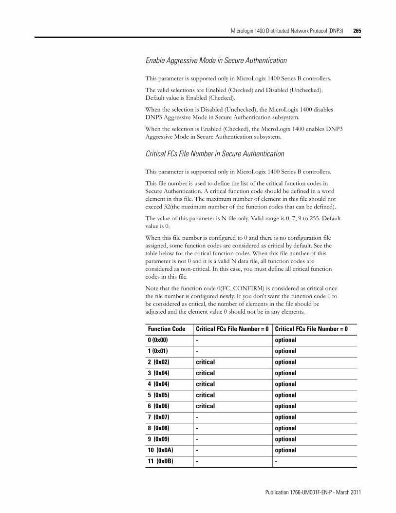
Micrologix 1400 Distributed Network Protocol (DNP3) 265
Enable Aggressive Mode in Secure Authentication
This parameter is supported only in MicroLogix 1400 Series B controllers.
The valid selections are Enabled (Checked) and Disabled (Unchecked). Default value is Enabled (Checked).
When the selection is Disabled (Unchecked), the MicroLogix 1400 disables DNP3 Aggressive Mode in Secure Authentication subsystem.
When the selection is Enabled (Checked), the MicroLogix 1400 enables DNP3 Aggressive Mode in Secure Authentication subsystem.
Critical FCs File Number in Secure Authentication
This parameter is supported only in MicroLogix 1400 Series B controllers.
This file number is used to define the list of the critical function codes in Secure Authentication. A critical function code should be defined in a word element in this file. The maximum number of element in this file should not exceed 32(the maximum number of the function codes that can be defined).
The value of this parameter is N file only. Valid range is 0, 7, 9 to 255. Default value is 0.
When this file number is configured to 0 and there is no configuration file assigned, some function codes are considered as critical by default. See the table below for the critical function codes. When this file number of this parameter is not 0 and it is a valid N data file, all function codes are considered as non-critical. In this case, you must define all critical function codes in this file.
Note that the function code 0(FC_CONFIRM) is considered as critical once the file number is configured newly. If you don't want the function code 0 to be considered as critical, the number of elements in the file should be adjusted and the element value 0 should not be in any elements.
Function Code Critical FCs File Number = 0 Critical FCs File Number = 0
0 (0x00) - optional
1 (0x01) - optional
2 (0x02) critical optional
3 (0x04) critical optional
4 (0x04) critical optional
5 (0x05) critical optional
6 (0x06) critical optional
7 (0x07) - optional
8 (0x08) - optional
9 (0x09) - optional
10 (0x0A) - optional
11 (0x0B) - -
Publication 1766-UM001F-EN-P - March 2011
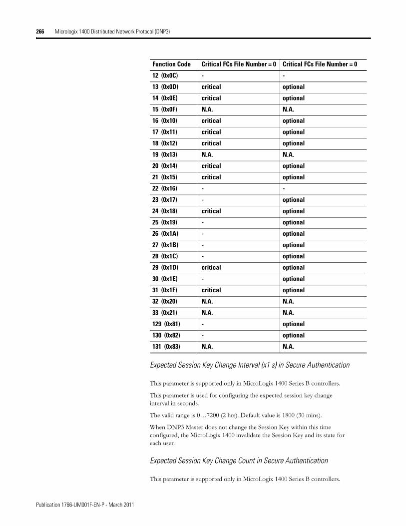
266 Micrologix 1400 Distributed Network Protocol (DNP3)
Expected Session Key Change Interval (x1 s) in Secure Authentication
This parameter is supported only in MicroLogix 1400 Series B controllers.
This parameter is used for configuring the expected session key change interval in seconds.
The valid range is 0…7200 (2 hrs). Default value is 1800 (30 mins).
When DNP3 Master does not change the Session Key within this time configured, the MicroLogix 1400 invalidate the Session Key and its state for each user.
Expected Session Key Change Count in Secure Authentication
This parameter is supported only in MicroLogix 1400 Series B controllers.
12 (0x0C) - -
13 (0x0D) critical optional
14 (0x0E) critical optional
15 (0x0F) N.A. N.A.
16 (0x10) critical optional
17 (0x11) critical optional
18 (0x12) critical optional
19 (0x13) N.A. N.A.
20 (0x14) critical optional
21 (0x15) critical optional
22 (0x16) - -
23 (0x17) - optional
24 (0x18) critical optional
25 (0x19) - optional
26 (0x1A) - optional
27 (0x1B) - optional
28 (0x1C) - optional
29 (0x1D) critical optional
30 (0x1E) - optional
31 (0x1F) critical optional
32 (0x20) N.A. N.A.
33 (0x21) N.A. N.A.
129 (0x81) - optional
130 (0x82) - optional
131 (0x83) N.A. N.A.
Function Code Critical FCs File Number = 0 Critical FCs File Number = 0
Publication 1766-UM001F-EN-P - March 2011
Micrologix 1400 Distributed Network Protocol (DNP3) 267
This parameter is used for configuring the expected session key change count.
The valid range is 1 to 10000. Default value is 2000.
Reply Timeout (x100 ms) in Secure Authentication
This parameter is supported only in MicroLogix 1400 Series B controllers.
This parameter is used for configuring the reply timeout in 100 msec.
The valid range is 0…1200 (120 s). Default value is 20 (2 s).
Maximum Error Count in Secure Authentication
This parameter is supported only in MicroLogix 1400 Series B controllers.
This parameter is used for configuring the maximum error count.
The valid range is 0…10. Default value is 2.
HMAC Algorithm in Secure Authentication
This parameter is supported only in MicroLogix 1400 Series B controllers.
This parameter is used for configuring the HMAC Algorithm.
• 1 = HMAC SHA-1 truncated to 4 octets (serial)
• 2 = HMAC SHA-1 truncated to 10 octets (networked)
• 3 = HMAC SHA-256 truncated to 8 octets (serial)
• 4 = HMAC SHA-256 truncated to 16 octets (networked)
The valid range is 1…4. Default value is 2.
User Info Config File Number in Secure Authentication
This parameter is supported only in MicroLogix 1400 Series B controllers.
This file number is used to define user information Secure Authentication.
The value of this parameter is N file only. Valid range is 0, 7, 9…255. Default value is 0.
Publication 1766-UM001F-EN-P - March 2011
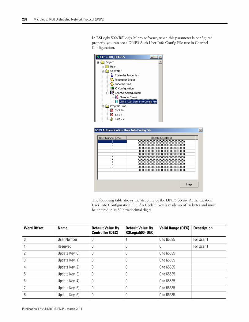
268 Micrologix 1400 Distributed Network Protocol (DNP3)
In RSLogix 500/RSLogix Micro software, when this parameter is configured properly, you can see a DNP3 Auth User Info Config File tree in Channel Configuration.
The following table shows the structure of the DNP3 Secure Authentication User Info Configuration File. An Update Key is made up of 16 bytes and must be entered in as 32 hexadecimal digits.
Word Offset Name Default Value By Controller (DEC)
Default Value By RSLogix500 (DEC)
Valid Range (DEC) Description
0 User Number 0 1 0 to 65535 For User 1
1 Reserved 0 0 0 For User 1
2 Update Key (0) 0 0 0 to 65535
3 Update Key (1) 0 0 0 to 65535
4 Update Key (2) 0 0 0 to 65535
5 Update Key (3) 0 0 0 to 65535
6 Update Key (4) 0 0 0 to 65535
7 Update Key (5) 0 0 0 to 65535
8 Update Key (6) 0 0 0 to 65535
Publication 1766-UM001F-EN-P - March 2011
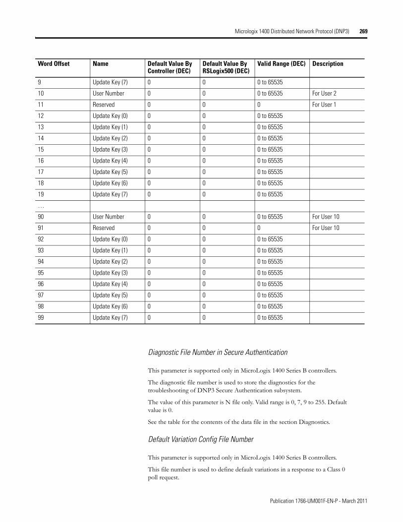
Micrologix 1400 Distributed Network Protocol (DNP3) 269
Diagnostic File Number in Secure Authentication
This parameter is supported only in MicroLogix 1400 Series B controllers.
The diagnostic file number is used to store the diagnostics for the troubleshooting of DNP3 Secure Authentication subsystem.
The value of this parameter is N file only. Valid range is 0, 7, 9 to 255. Default value is 0.
See the table for the contents of the data file in the section Diagnostics.
Default Variation Config File Number
This parameter is supported only in MicroLogix 1400 Series B controllers.
This file number is used to define default variations in a response to a Class 0 poll request.
9 Update Key (7) 0 0 0 to 65535
10 User Number 0 0 0 to 65535 For User 2
11 Reserved 0 0 0 For User 1
12 Update Key (0) 0 0 0 to 65535
13 Update Key (1) 0 0 0 to 65535
14 Update Key (2) 0 0 0 to 65535
15 Update Key (3) 0 0 0 to 65535
16 Update Key (4) 0 0 0 to 65535
17 Update Key (5) 0 0 0 to 65535
18 Update Key (6) 0 0 0 to 65535
19 Update Key (7) 0 0 0 to 65535
…
90 User Number 0 0 0 to 65535 For User 10
91 Reserved 0 0 0 For User 10
92 Update Key (0) 0 0 0 to 65535
93 Update Key (1) 0 0 0 to 65535
94 Update Key (2) 0 0 0 to 65535
95 Update Key (3) 0 0 0 to 65535
96 Update Key (4) 0 0 0 to 65535
97 Update Key (5) 0 0 0 to 65535
98 Update Key (6) 0 0 0 to 65535
99 Update Key (7) 0 0 0 to 65535
Word Offset Name Default Value By Controller (DEC)
Default Value By RSLogix500 (DEC)
Valid Range (DEC) Description
Publication 1766-UM001F-EN-P - March 2011
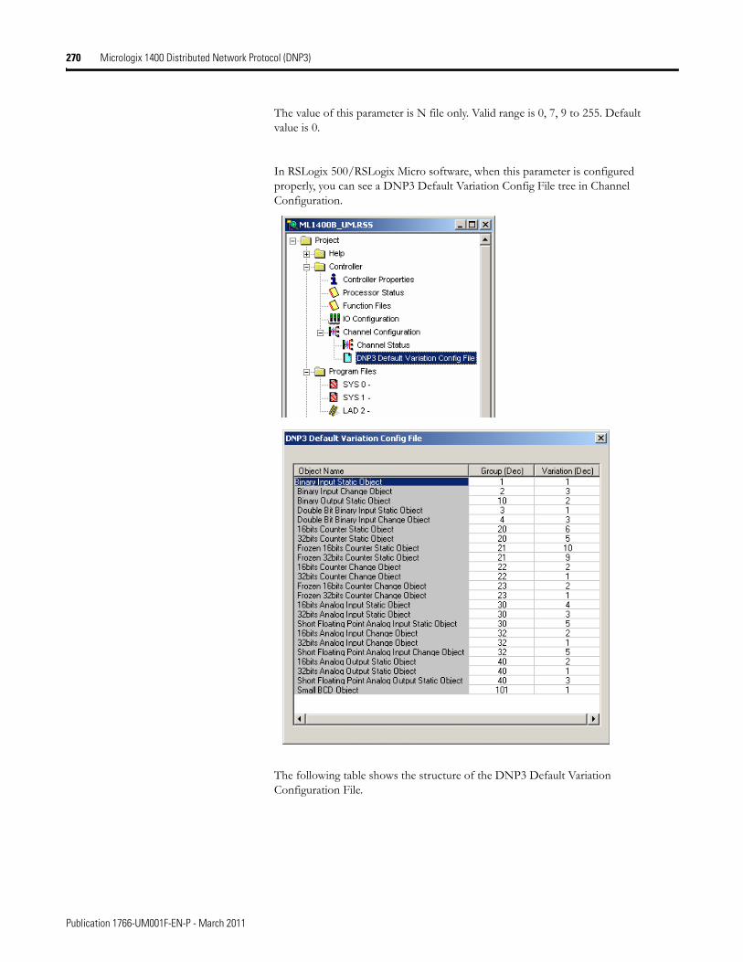
270 Micrologix 1400 Distributed Network Protocol (DNP3)
The value of this parameter is N file only. Valid range is 0, 7, 9 to 255. Default value is 0.
In RSLogix 500/RSLogix Micro software, when this parameter is configured properly, you can see a DNP3 Default Variation Config File tree in Channel Configuration.
The following table shows the structure of the DNP3 Default Variation Configuration File.
Publication 1766-UM001F-EN-P - March 2011
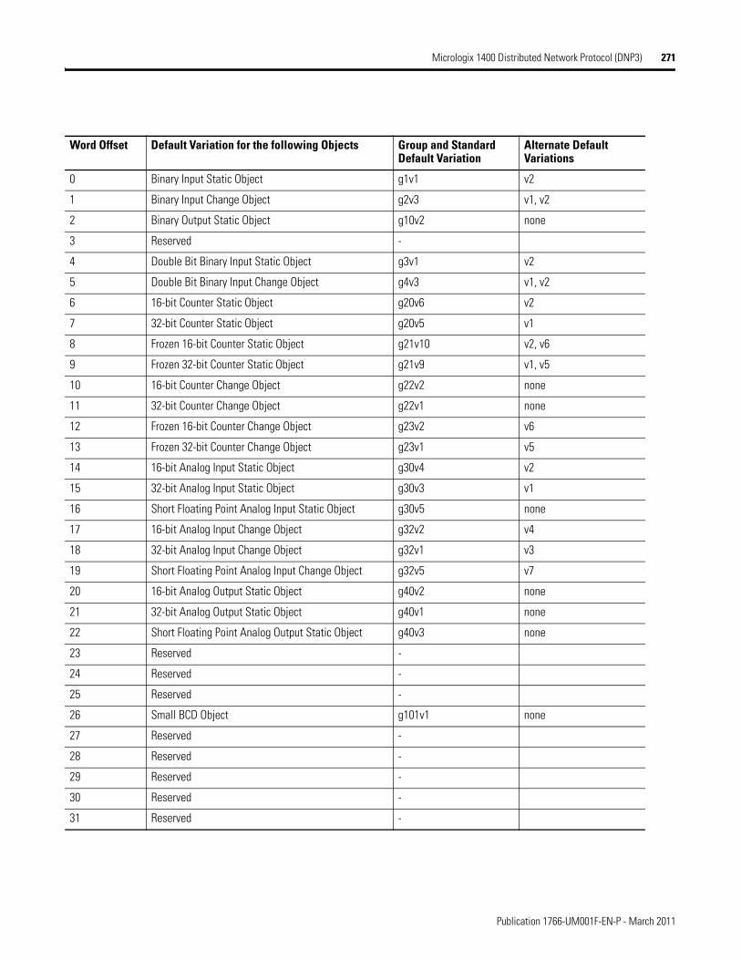
Micrologix 1400 Distributed Network Protocol (DNP3) 271
Word Offset Default Variation for the following Objects Group and Standard Default Variation
Alternate Default Variations
0 Binary Input Static Object g1v1 v2
1 Binary Input Change Object g2v3 v1, v2
2 Binary Output Static Object g10v2 none
3 Reserved -
4 Double Bit Binary Input Static Object g3v1 v2
5 Double Bit Binary Input Change Object g4v3 v1, v2
6 16-bit Counter Static Object g20v6 v2
7 32-bit Counter Static Object g20v5 v1
8 Frozen 16-bit Counter Static Object g21v10 v2, v6
9 Frozen 32-bit Counter Static Object g21v9 v1, v5
10 16-bit Counter Change Object g22v2 none
11 32-bit Counter Change Object g22v1 none
12 Frozen 16-bit Counter Change Object g23v2 v6
13 Frozen 32-bit Counter Change Object g23v1 v5
14 16-bit Analog Input Static Object g30v4 v2
15 32-bit Analog Input Static Object g30v3 v1
16 Short Floating Point Analog Input Static Object g30v5 none
17 16-bit Analog Input Change Object g32v2 v4
18 32-bit Analog Input Change Object g32v1 v3
19 Short Floating Point Analog Input Change Object g32v5 v7
20 16-bit Analog Output Static Object g40v2 none
21 32-bit Analog Output Static Object g40v1 none
22 Short Floating Point Analog Output Static Object g40v3 none
23 Reserved -
24 Reserved -
25 Reserved -
26 Small BCD Object g101v1 none
27 Reserved -
28 Reserved -
29 Reserved -
30 Reserved -
31 Reserved -
Publication 1766-UM001F-EN-P - March 2011
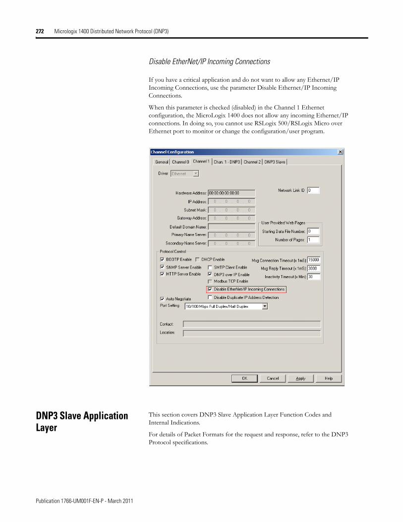
272 Micrologix 1400 Distributed Network Protocol (DNP3)
Disable EtherNet/IP Incoming Connections
If you have a critical application and do not want to allow any Ethernet/IP Incoming Connections, use the parameter Disable Ethernet/IP Incoming Connections.
When this parameter is checked (disabled) in the Channel 1 Ethernet configuration, the MicroLogix 1400 does not allow any incoming Ethernet/IP connections. In doing so, you cannot use RSLogix 500/RSLogix Micro over Ethernet port to monitor or change the configuration/user program.
DNP3 Slave Application Layer
This section covers DNP3 Slave Application Layer Function Codes and Internal Indications.
For details of Packet Formats for the request and response, refer to the DNP3 Protocol specifications.
Publication 1766-UM001F-EN-P - March 2011
Micrologix 1400 Distributed Network Protocol (DNP3) 273
Function Codes
FC_CONFIRM (FC Byte = 0x00)
00 - Confirm
A DNP3 master sends a message with this function code to confirm receipt of a response fragment. In a general environment, the MicroLogix 1400 receives a response with this function code. But the MicroLogix 1400 may generate a response with this function code when a DNP3 Master sends a request with the CON bit set in the application control header.
FC_READ (FC Byte = 0x01)
01 - Read
The READ function code is used by a DNP3 master to request data from the MicroLogix 1400.
FC_WRITE (FC Byte = 0x02)
02 - Write
The WRITE function code is used to write the contents of DNP3 objects from the DNP3 master to the MicroLogix 1400. This function code is used for clearing bit IIN1.7 [DEVICE_RESTART], setting time in the MicroLogix 1400 and downloading user programs to the MicroLogix 1400 controller.
FC_SELECT (FC Byte = 0x03)
03 - Select
The SELECT function code is used in conjunction with the OPERATE function code as part of select-before-operate method for issuing control requests. This procedure is used for controlling binary output (CROB) or analog output (AOB) objects.
FC_OPERATE (FC Byte = 0x04)
04 - Operate
See the comment for FC_SELECT (FC Byte = 0x03) on page 273.
FC_DIRECT_OPERATE (FC Byte = 0x05)
05 - Direct Operate
This direct operate function is similar to the FC_OPERATE function code except that no preceding select command is required.
FC_DIRECT_OPERATE_NR (FC Byte = 0x06)
06 - Direct Operate No Resp
Publication 1766-UM001F-EN-P - March 2011
274 Micrologix 1400 Distributed Network Protocol (DNP3)
See the comment for FC_DIRECT_OPERATE. No response message is returned when this request is issued from a DNP3 master.
FC_IMMED_FREEZE (FC Byte = 0x07)
07 - Immediate Freeze
Upon receiving a request with this function, the MicroLogix 1400 copies the current value of a counter point to a separate memory location associated with the same point. The copied value remains constant until the next freeze operation to the same point.
FC_IMMED_FREEZE_NR (FC Byte = 0x08)
08 - Immediate Freeze No Resp
See the comment for FC_IMMED_FREEZE. No response message is returned when this request is issued from a DNP3 master..
FC_FREEZE_CLEAR (FC Byte = 0x09)
09 - Freeze and Clear
Upon receiving a request with this function, the MicroLogix 1400 copies the current value to the frozen value, then clears the current value to 0 immediately.
FC_FREEZE_CLEAR_NR (FC Byte = 0x0A)
10 - Freeze and Clear No Resp
See the comment for FC_FREEZE_CLEAR. No response message is returned when this request is issued from a DNP3 master.
FC_COLD_RESTART (FC Byte = 0x0D)
13 - Cold Restart
This function code forces the MicroLogix 1400 to perform a complete restart upon powering up.
FC_WARM_RESTART (FC Byte = 0x0E)
14 - Warm Restart
This function code forces the MicroLogix 1400 to perform a partial reset. This applies only to the MicroLogix 1400 Series B controller.
FC_INITIALIZE_APPL (FC Byte = 0x10)
16 - Initialize Application
This function code is used to initialize the user program which was downloaded by RSLogix 500/RSLogix Micro software.
Publication 1766-UM001F-EN-P - March 2011

Micrologix 1400 Distributed Network Protocol (DNP3) 275
FC_START_APPL (FC Byte = 0x11)
17 - Start Application
This function code is used to start the user program which was downloaded by RSLogix 500/RSLogix Micro software.
FC_STOP_APPL (FC Byte = 0x12)
18 - Stop Application
This function code is used to stop the user program which was downloaded by RSLogix 500/RSLogix Micro.
FC_ENABLE_UNSOLICITED (FC Byte = 0x14)
20 - Enable Unsolicited Message
This function is used to dynamically enable unsolicited messages generated in the MicroLogix 1400.
FC_DISABLE_UNSOLICITED (FC Byte = 0x15)
21 - Disable Unsolicited Message
This function is used to dynamically disable unsolicited messages generated in the MicroLogix 1400.
FC_DELAY_MEASURE (FC Byte = 0x17)
23 - Delay Measurement, used for Non-LAN Procedure
This function code is used to measure the communication channel delay time.
FC_RECORD_CURRENT_TIME (FC Byte = 0x18)
24 - Record Current Time, used for LAN Procedure
This function code is used in the procedure for time synchronizing MicroLogix 1400 controllers that communicate over a LAN. This applies only to MicroLogix 1400 Series B controllers.
FC_OPEN_FILE (FC Byte = 0x19)
25 - Open File
This function code is used to make a file available for reading or writing.
FC_CLOSE_FILE (FC Byte = 0x1A)
26 - Close File
Publication 1766-UM001F-EN-P - March 2011
276 Micrologix 1400 Distributed Network Protocol (DNP3)
After the file reading or writing operation, this function code used to unlock the file.
FC_DELETE_FILE (FC Byte = 0x1B)
27 - Delete File
A DNP3 master uses this function code to delete a file.
FC_GET_FILE_INFO (FC Byte = 0x1C)
28 - Get File Information
This function code is for the master to retrieve information about a file in the MicroLogix 1400. This applies only to MicroLogix 1400 Series B controllers.
FC_AUTHENTICATE_FILE (FC Byte = 0x1D)
29 - Authenticate File
This function code is used to obtain an authentication key that is needed to open or delete a file.
FC_ABORT_FILE (FC Byte = 0x1E)
30 - Abort File
This function code is used to immediately request termination of the current read/write operation and close the file, without saving.
This applies only to MicroLogix 1400 Series B controllers.
FC_ACTIVATE_CONFIG (FC Byte = 0x1F)
31 - Activate Config
This function code is used to begin using the configuration or executable code specified by the objects included in the request.
This applies only to MicroLogix 1400 Series B controllers.
FC_AUTHENTICATION_REQUEST (FC Byte = 0x20)
32 - Authentication Request
The master uses this function code when sending authentication messages to the MicroLogix 1400 that require a response
This applies only to MicroLogix 1400 Series B controllers.
FC_AUTHENTICATION_REQUEST_NR (FC Byte = 0x21)
33 - Authentication Request No Resp
Publication 1766-UM001F-EN-P - March 2011
Micrologix 1400 Distributed Network Protocol (DNP3) 277
This function code is used by the master to send authentication messages when no return response is required.
This applies only to MicroLogix 1400 Series B controllers.
FC_RESPONSE (FC Byte = 0x81)
129 - Response
All responses except for Unsolicited Response messages use this function code.
FC_UNSOLICITED_RESPONSE (FC Byte = 0x82)
130 - Unsolicited Response
Unsolicited Responses always use this function code regardless of which DNP3 objects are included.
FC_AUTHENTICATION_RESPONSE (FC Byte = 0x83)
131 - Authentication Response
This function code is used to issue authentication messages to the master. This applies only to MicroLogix 1400 Series B controllers.
Internal Indications
Internal Indication bits are set under the following conditions of the MicroLogix 1400 controllers:
• IIN1.0: ALL_STATIONS. This bit is set when an all-stations message is received.
• IIN1.1: CLASS_1_EVENTS. This bit is set when Class 1 event data is available.
• IIN1.2: CLASS_2_EVENTS. This bit is set when Class 2 event data is available.
• IIN1.3: CLASS_3_EVENTS. This bit is set when Class 3 event data is available.
• IIN1.4: NEED_TIME. This bit is set when Time synchronization is required.
• IIN1.5: LOCAL_CONTROL. This bit is set when the controller is in Non-Executing mode.
• IIN1.6: DEVICE_TROUBLE. This bit is set when the controller is in Fault mode.
• IIN1.7: DEVICE_RESTART. This bit is set when the DNP3 driver is just configured, in channel configuration .
• IIN2.0: NO_FUNC_CODE_SUPPORT. This bit is set when a request which has an unknown function code is received.
Publication 1766-UM001F-EN-P - March 2011
278 Micrologix 1400 Distributed Network Protocol (DNP3)
• IIN2.1: OBJECT_UNKNOWN. This bit is set when a request which has an unknown object is received.
• IIN2.2: PARAMETER_ERROR. This bit is set when a request with a qualifier/range field that cannot be processed is received.
• IIN2.3: EVENT_BUFFER_OVERFLOW. This bit is set when an event buffer overflow condition exists in the controller and at least one unconfirmed event is lost.
• IIN2.4: ALREADY_EXECUTING. Not supported.
• IIN2.5: CONFIG_CORRUPT. This bit is set when a bad file type and bad file number are detected.
• IIN2.6: Reserved.
• IIN2.7: Reserved.
You can access the last transmitted IIN bits in the response through accessing the element of Communication Status file, CS0:58 or CS2:58. For more details, see Diagnostics.
DNP3 Objects and MicroLogix 1400 Data Files
All of the DNP3 Objects which are supported in the MicroLogix 1400 are summarized in Implementation Table on page 364.
Data file types used in DNP3 Objects are not the same as that used in the MicroLogix controller, but are similar. Mapping is required between DNP3 data files and MicroLogix 1400 data files.
Overview
DNP3 Data objects that are implemented in the MicroLogix 1400 controller are listed below:
• DNP3 Binary Input Object
• DNP3 Double Bit Binary Input Object
• DNP3 Binary Output Object
• DNP3 Counter Object
• DNP3 Frozen Counter Object
• DNP3 Analog Input Object
• DNP3 Analog Output Object
• DNP3 BCD Object
• DNP3 Data Set Object (Series B controllers only)
Some of objects are divided into several Object files to map data files in the MicroLogix 1400 controller.
• Counter Object — 16bit and 32bit Counter Object File
• Analog Input Object — 16bit and 32bit Analog Input Object File, and Short Floating Point Analog Input Object File.
• Analog Output Object — 16bit and 32bit Analog Output Object File, and Short Floating Point Analog Output Object File.
Publication 1766-UM001F-EN-P - March 2011
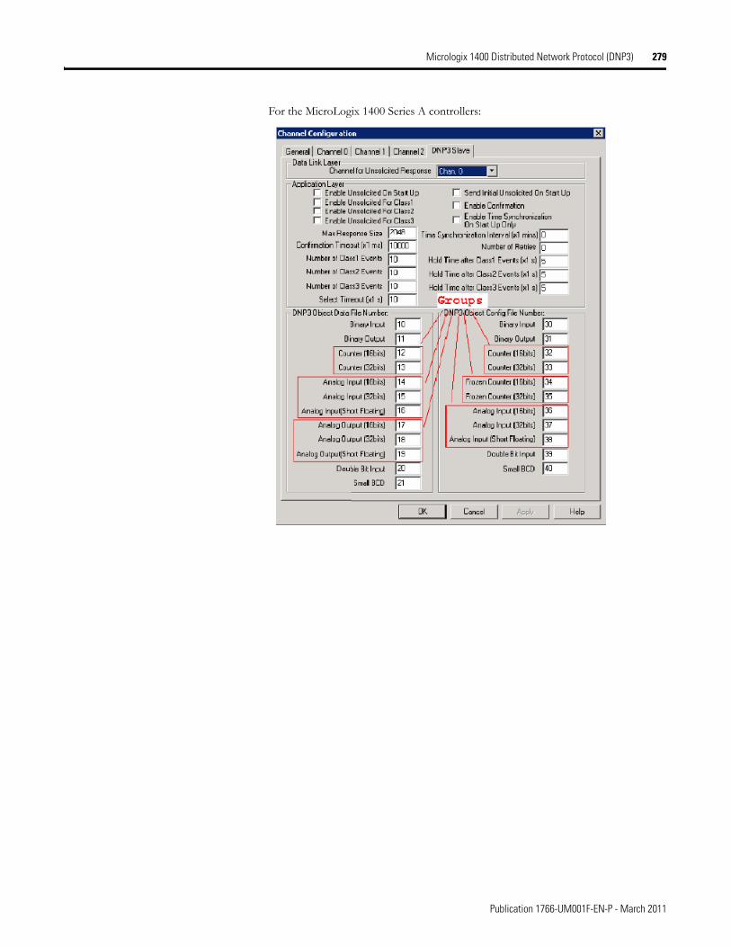
Micrologix 1400 Distributed Network Protocol (DNP3) 279
For the MicroLogix 1400 Series A controllers:
Publication 1766-UM001F-EN-P - March 2011
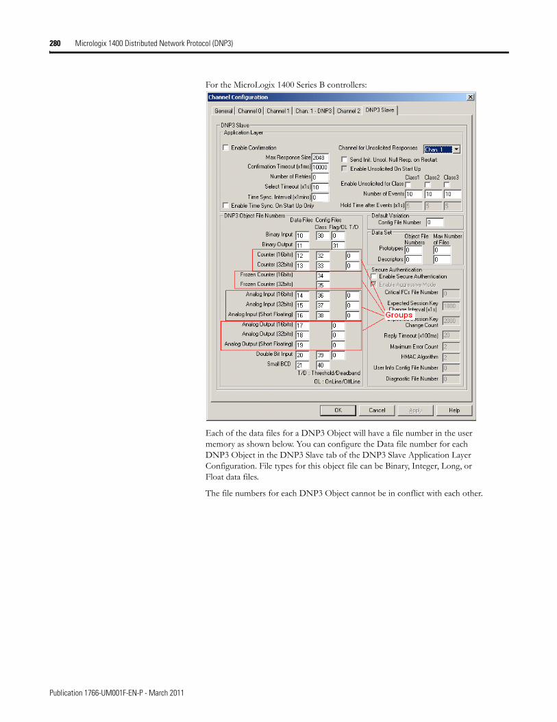
280 Micrologix 1400 Distributed Network Protocol (DNP3)
For the MicroLogix 1400 Series B controllers:
Each of the data files for a DNP3 Object will have a file number in the user memory as shown below. You can configure the Data file number for each DNP3 Object in the DNP3 Slave tab of the DNP3 Slave Application Layer Configuration. File types for this object file can be Binary, Integer, Long, or Float data files.
The file numbers for each DNP3 Object cannot be in conflict with each other.
Publication 1766-UM001F-EN-P - March 2011
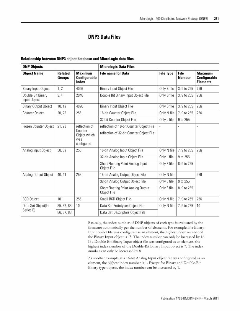
Micrologix 1400 Distributed Network Protocol (DNP3) 281
DNP3 Data Files
Basically, the index number of DNP objects of each type is evaluated by the firmware automatically per the number of elements. For example, if a Binary Input object file was configured as an element, the highest index number of the Binary Input object is 15. The index number can only be increased by 16. If a Double-Bit Binary Input object file was configured as an element, the highest index number of the Double-Bit Binary Input object is 7. The index number can only be increased by 8.
As another example, if a 16-bit Analog Input object file was configured as an element, the highest index number is 1. Except for Binary and Double-Bit Binary type objects, the index number can be increased by 1.
Relationship between DNP3 object database and MicroLogix data files
DNP Objects Micrologix Data Files
Object Name Related Groups
Maximum Configurable Index
File name for Data File Type File Number
Maximum Configurable Elements
Binary Input Object 1, 2 4096 Binary Input Object File Only B file 3, 9 to 255 256
Double Bit Binary Input Object
3, 4 2048 Double Bit Binary Input Object File Only B file 3, 9 to 255 256
Binary Output Object 10, 12 4096 Binary Input Object File Only B file 3, 9 to 255 256
Counter Object 20, 22 256 16-bit Counter Object File Only N file 7, 9 to 255 256
32 bit Counter Object File Only L file 9 to 255
Frozen Counter Object 21, 23 reflection of Counter Object which was configured
reflection of 16-bit Counter Object File - - -
reflection of 32-bit Counter Object File
Analog Input Object 30, 32 256 16-bit Analog Input Object File Only N file 7, 9 to 255 256
32-bit Analog Input Object File Only L file 9 to 255
Short Floating Point Analog Input Object File
Only F file 8, 9 to 255
Analog Output Object 40, 41 256 16-bit Analog Output Object File Only N file 256
32-bit Analog Output Object File Only L file 9 to 255
Short Floating Point Analog Output Object File
Only F file 8, 9 to 255
BCD Object 101 256 Small BCD Object File Only N file 7, 9 to 255 256
Data Set Object(In Series B)
85, 87, 88 10 Data Set Prototypes Object File Only N file 7, 9 to 255 10
86, 87, 88 Data Set Descriptors Object File
Publication 1766-UM001F-EN-P - March 2011
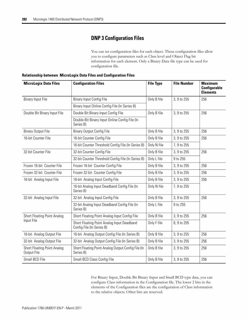
282 Micrologix 1400 Distributed Network Protocol (DNP3)
DNP 3 Configuration Files
You can set configuration files for each object. These configuration files allow you to configure parameters such as Class level and Object Flag bit information for each element. Only a Binary Data file type can be used for configuration file.
For Binary Input, Double Bit Binary Input and Small BCD type data, you can configure Class information in the Configuration file. The lower 2 bits in the elements of the Configuration files are the configuration of Class information to the relative objects. Other bits are reserved.
Relationship between MicroLogix Data Files and Configuration Files
MicroLogix Data Files Configuration Files File Type File Number Maximum Configurable Elements
Binary Input File Binary Input Config File Only B file 3, 9 to 255 256
Binary Input Online Config File (In Series B)
Double Bit Binary Input File Double Bit Binary Input Config File Only B file 3, 9 to 255 256
Double-Bit Binary Input Online Config File (In Series B)
Binary Output File Binary Output Config File Only B file 3, 9 to 255 256
16-bit Counter File 16-bit Counter Config File Only B file 3, 9 to 255 256
16-bit Counter Threshold Config File (In Series B) Only N file 7, 9 to 255
32-bit Counter File 32-bit Counter Config File Only B file 3, 9 to 255 256
32-bit Counter Threshold Config File (In Series B) Only L file 9 to 255
Frozen 16-bit Counter File Frozen 16-bit Counter Config File Only B file 3, 9 to 255 256
Frozen 32-bit Counter File Frozen 32-bit Counter Config File Only B file 3, 9 to 255 256
16-bit Analog Input File 16-bit Analog Input Config File Only B file 3, 9 to 255 256
16-bit Analog Input Deadband Config File (In Series B)
Only N file 7, 9 to 255
32-bit Analog Input File 32-bit Analog Input Config File Only B file 3, 9 to 255 256
32-bit Analog Input Deadband Config File (In Series B)
Only L file 9 to 255
Short Floating Point Analog Input File
Short Floating Point Analog Input Config File Only B file 3, 9 to 255 256
Short Floating Point Analog Input Deadband Config File (In Series B)
Only F file 8, 9 to 255
16-bit Analog Output File 16-bit Analog Output Config File (In Series B) Only B file 3, 9 to 255 256
32-bit Analog Output File 32-bit Analog Output Config File (In Series B) Only B file 3, 9 to 255 256
Short Floating Point Analog Output File
Short Floating Point Analog Output Config File (In Series B)
Only B file 3, 9 to 255 256
Small BCD File Small BCD Class Config File Only B file 3, 9 to 255 256
Publication 1766-UM001F-EN-P - March 2011
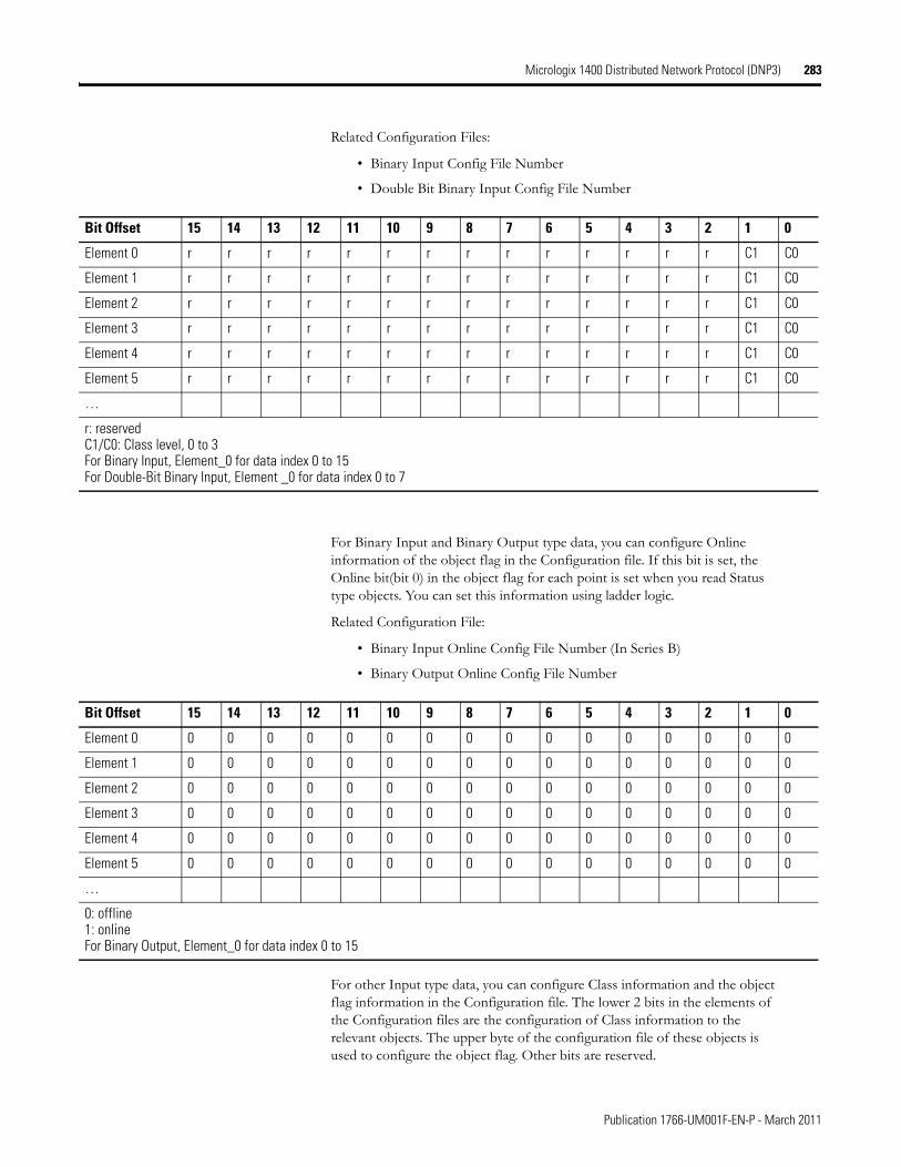
Micrologix 1400 Distributed Network Protocol (DNP3) 283
Related Configuration Files:
• Binary Input Config File Number
• Double Bit Binary Input Config File Number
For Binary Input and Binary Output type data, you can configure Online information of the object flag in the Configuration file. If this bit is set, the Online bit(bit 0) in the object flag for each point is set when you read Status type objects. You can set this information using ladder logic.
Related Configuration File:
• Binary Input Online Config File Number (In Series B)
• Binary Output Online Config File Number
For other Input type data, you can configure Class information and the object flag information in the Configuration file. The lower 2 bits in the elements of the Configuration files are the configuration of Class information to the relevant objects. The upper byte of the configuration file of these objects is used to configure the object flag. Other bits are reserved.
Bit Offset 15 14 13 12 11 10 9 8 7 6 5 4 3 2 1 0
Element 0 r r r r r r r r r r r r r r C1 C0
Element 1 r r r r r r r r r r r r r r C1 C0
Element 2 r r r r r r r r r r r r r r C1 C0
Element 3 r r r r r r r r r r r r r r C1 C0
Element 4 r r r r r r r r r r r r r r C1 C0
Element 5 r r r r r r r r r r r r r r C1 C0
…
r: reservedC1/C0: Class level, 0 to 3For Binary Input, Element_0 for data index 0 to 15For Double-Bit Binary Input, Element _0 for data index 0 to 7
Bit Offset 15 14 13 12 11 10 9 8 7 6 5 4 3 2 1 0
Element 0 0 0 0 0 0 0 0 0 0 0 0 0 0 0 0 0
Element 1 0 0 0 0 0 0 0 0 0 0 0 0 0 0 0 0
Element 2 0 0 0 0 0 0 0 0 0 0 0 0 0 0 0 0
Element 3 0 0 0 0 0 0 0 0 0 0 0 0 0 0 0 0
Element 4 0 0 0 0 0 0 0 0 0 0 0 0 0 0 0 0
Element 5 0 0 0 0 0 0 0 0 0 0 0 0 0 0 0 0
…
0: offline1: onlineFor Binary Output, Element_0 for data index 0 to 15
Publication 1766-UM001F-EN-P - March 2011
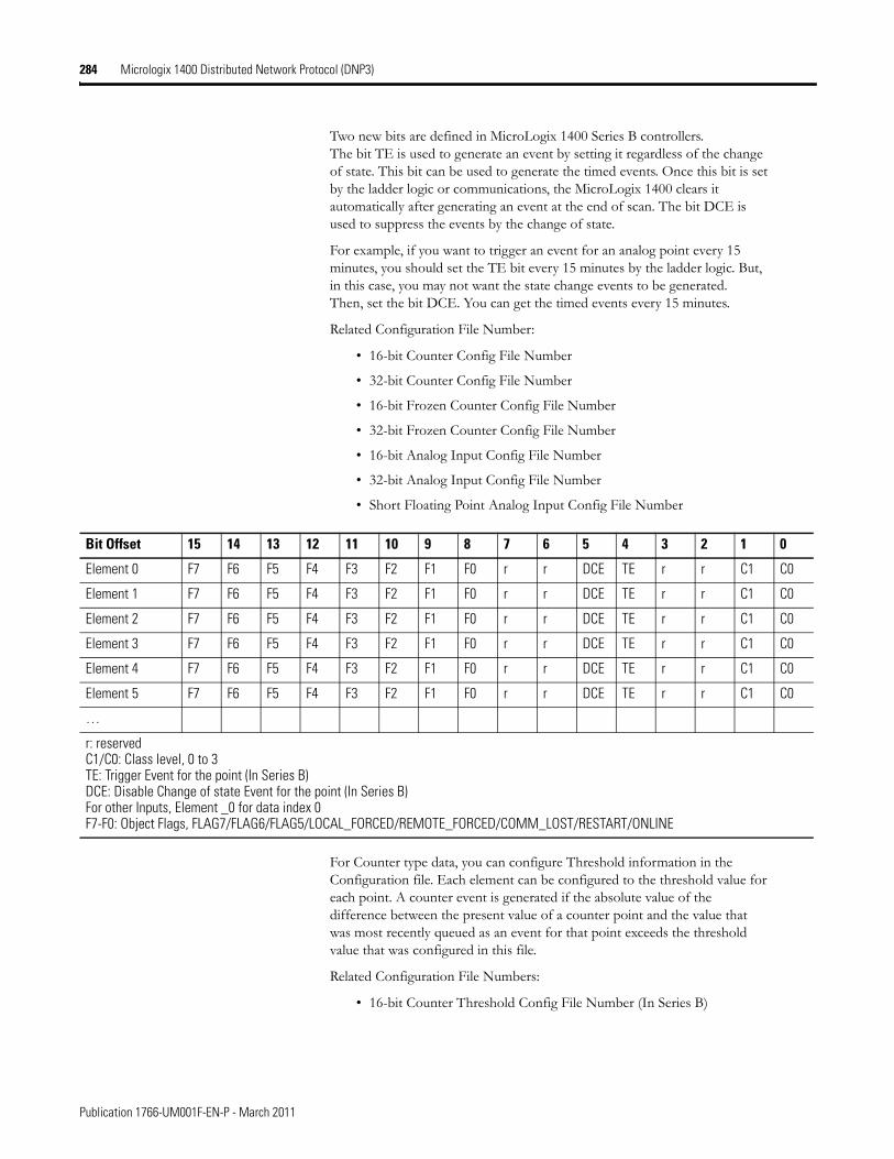
284 Micrologix 1400 Distributed Network Protocol (DNP3)
Two new bits are defined in MicroLogix 1400 Series B controllers. The bit TE is used to generate an event by setting it regardless of the change of state. This bit can be used to generate the timed events. Once this bit is set by the ladder logic or communications, the MicroLogix 1400 clears it automatically after generating an event at the end of scan. The bit DCE is used to suppress the events by the change of state.
For example, if you want to trigger an event for an analog point every 15 minutes, you should set the TE bit every 15 minutes by the ladder logic. But, in this case, you may not want the state change events to be generated. Then, set the bit DCE. You can get the timed events every 15 minutes.
Related Configuration File Number:
• 16-bit Counter Config File Number
• 32-bit Counter Config File Number
• 16-bit Frozen Counter Config File Number
• 32-bit Frozen Counter Config File Number
• 16-bit Analog Input Config File Number
• 32-bit Analog Input Config File Number
• Short Floating Point Analog Input Config File Number
For Counter type data, you can configure Threshold information in the Configuration file. Each element can be configured to the threshold value for each point. A counter event is generated if the absolute value of the difference between the present value of a counter point and the value that was most recently queued as an event for that point exceeds the threshold value that was configured in this file.
Related Configuration File Numbers:
• 16-bit Counter Threshold Config File Number (In Series B)
Bit Offset 15 14 13 12 11 10 9 8 7 6 5 4 3 2 1 0
Element 0 F7 F6 F5 F4 F3 F2 F1 F0 r r DCE TE r r C1 C0
Element 1 F7 F6 F5 F4 F3 F2 F1 F0 r r DCE TE r r C1 C0
Element 2 F7 F6 F5 F4 F3 F2 F1 F0 r r DCE TE r r C1 C0
Element 3 F7 F6 F5 F4 F3 F2 F1 F0 r r DCE TE r r C1 C0
Element 4 F7 F6 F5 F4 F3 F2 F1 F0 r r DCE TE r r C1 C0
Element 5 F7 F6 F5 F4 F3 F2 F1 F0 r r DCE TE r r C1 C0
…
r: reservedC1/C0: Class level, 0 to 3TE: Trigger Event for the point (In Series B)DCE: Disable Change of state Event for the point (In Series B)For other Inputs, Element _0 for data index 0F7-F0: Object Flags, FLAG7/FLAG6/FLAG5/LOCAL_FORCED/REMOTE_FORCED/COMM_LOST/RESTART/ONLINE
Publication 1766-UM001F-EN-P - March 2011
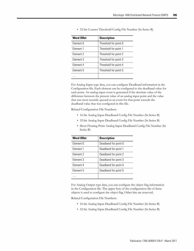
Micrologix 1400 Distributed Network Protocol (DNP3) 285
• 32-bit Counter Threshold Config File Number (In Series B)
For Analog Input type data, you can configure Deadband information in the Configuration file. Each element can be configured to the deadband value for each point. An analog input event is generated if the absolute value of the difference between the present value of an analog input point and the value that was most recently queued as an event for that point exceeds the deadband value that was configured in this file.
Related Configuration File Numbers:
• 16-bit Analog Input Deadband Config File Number (In Series B)
• 32-bit Analog Input Deadband Config File Number (In Series B)
• Short Floating Point Analog Input Deadband Config File Number (In Series B)
For Analog Output type data, you can configure the object flag information in the Configuration file. The upper byte of the configuration file of these objects is used to configure the object flag. Other bits are reserved.
Related Configuration File Numbers:
• 16-bit Analog Input Deadband Config File Number (In Series B)
• 32-bit Analog Input Deadband Config File Number (In Series B)
Word Offet Description
Element 0 Threshold for point 0
Element 1 Threshold for point 1
Element 2 Threshold for point 2
Element 3 Threshold for point 3
Element 4 Threshold for point 4
Element 5 Threshold for point 5
…
Word Offet Description
Element 0 Deadband for point 0
Element 1 Deadband for point 1
Element 2 Deadband for point 2
Element 3 Deadband for point 3
Element 4 Deadband for point 4
Element 5 Deadband for point 5
…
Publication 1766-UM001F-EN-P - March 2011
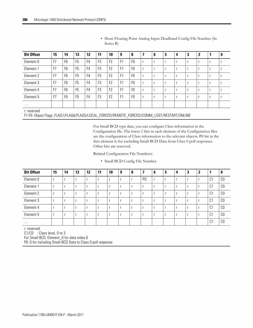
286 Micrologix 1400 Distributed Network Protocol (DNP3)
• Short Floating Point Analog Input Deadband Config File Number (In Series B)
For Small BCD type data, you can configure Class information in the Configuration file. The lower 2 bits in each element of the Configuration files are the configuration of Class information to the relevant objects. P0 bit in the first element is for excluding Small BCD Data from Class 0 poll responses. Other bits are reserved.
Related Configuration File Numbers:
• Small BCD Config File Number
Bit Offset 15 14 13 12 11 10 9 8 7 6 5 4 3 2 1 0
Element 0 F7 F6 F5 F4 F3 F2 F1 F0 r r r r r r r r
Element 1 F7 F6 F5 F4 F3 F2 F1 F0 r r r r r r r r
Element 2 F7 F6 F5 F4 F3 F2 F1 F0 r r r r r r r r
Element 3 F7 F6 F5 F4 F3 F2 F1 F0 r r r r r r r r
Element 4 F7 F6 F5 F4 F3 F2 F1 F0 r r r r r r r r
Element 5 F7 F6 F5 F4 F3 F2 F1 F0 r r r r r r r r
…
r: reservedF7-F0: Object Flags, FLAG7/FLAG6/FLAG5/LOCAL_FORCED/REMOTE_FORCED/COMM_LOST/RESTART/ONLINE
Bit Offset 15 14 13 12 11 10 9 8 7 6 5 4 3 2 1 0
Element 0 r r r r r r r r PO r r r r r C1 C0
Element 1 r r r r r r r r r r r r r r C1 C0
Element 2 r r r r r r r r r r r r r r C1 C0
Element 3 r r r r r r r r r r r r r r C1 C0
Element 4 r r r r r r r r r r r r r r C1 C0
Element 5 r r r r r r r r r r r r r r C1 C0
… C1 C0
r: reservedC1/C0 : Class level, 0 to 3For Small BCD, Element_0 for data index 0P0: 0 for including Small BCD Data to Class 0 poll response
Publication 1766-UM001F-EN-P - March 2011

Micrologix 1400 Distributed Network Protocol (DNP3) 287
DNP3 Binary Input Object
The supported object group and variations are listed in this section. The MicroLogix 1400 responds with the default group and variation when the DNP3 Master requests to read the object with all variations.
Binary Input Static Objects:
• g1v0 - Binary Input - All Variations
• g1v1 - Binary Input - Packed format (default)
• g1v2 - Binary Input - With flags
Binary Input Event Objects:
• g2v0 - Binary Input Event - All Variations
• g2v1 - Binary Input Event - Without time
• g2v2 - Binary Input Event - With absolute time
• g2v3 - Binary Input Event - With relative time (default)
Related Object File Number:
• Binary Input Object File Number
Related Configuration File Number:
• Binary Input Config File Number
To generate a Binary Input Object from the DNP3 Subsystem in the controller, you should configure Binary Input Object File Number in the DNP3 Slave Application Layer Configuration file.
When the Binary Input Object File is configured, Index number starts from 0. 1 bit is used for 1 Index.
Publication 1766-UM001F-EN-P - March 2011
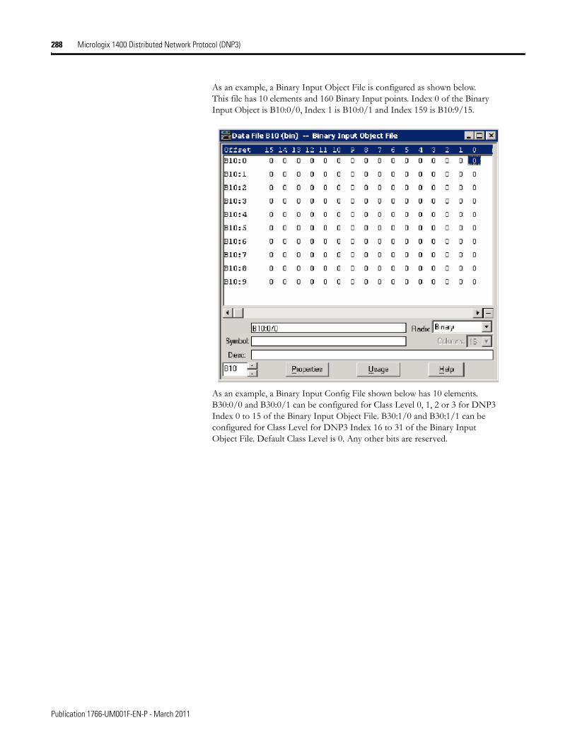
288 Micrologix 1400 Distributed Network Protocol (DNP3)
As an example, a Binary Input Object File is configured as shown below. This file has 10 elements and 160 Binary Input points. Index 0 of the Binary Input Object is B10:0/0, Index 1 is B10:0/1 and Index 159 is B10:9/15.
As an example, a Binary Input Config File shown below has 10 elements. B30:0/0 and B30:0/1 can be configured for Class Level 0, 1, 2 or 3 for DNP3 Index 0 to 15 of the Binary Input Object File. B30:1/0 and B30:1/1 can be configured for Class Level for DNP3 Index 16 to 31 of the Binary Input Object File. Default Class Level is 0. Any other bits are reserved.
Publication 1766-UM001F-EN-P - March 2011
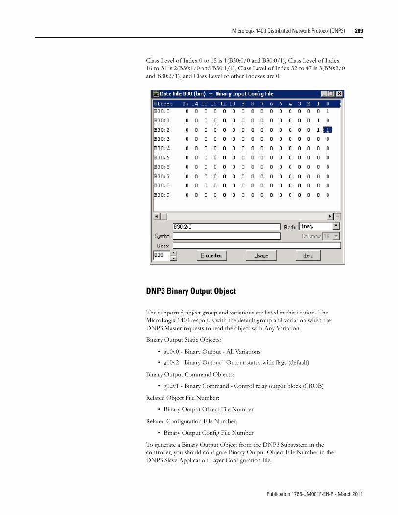
Micrologix 1400 Distributed Network Protocol (DNP3) 289
Class Level of Index 0 to 15 is 1(B30:0/0 and B30:0/1), Class Level of Index 16 to 31 is 2(B30:1/0 and B30:1/1), Class Level of Index 32 to 47 is 3(B30:2/0 and B30:2/1), and Class Level of other Indexes are 0.
DNP3 Binary Output Object
The supported object group and variations are listed in this section. The MicroLogix 1400 responds with the default group and variation when the DNP3 Master requests to read the object with Any Variation.
Binary Output Static Objects:
• g10v0 - Binary Output - All Variations
• g10v2 - Binary Output - Output status with flags (default)
Binary Output Command Objects:
• g12v1 - Binary Command - Control relay output block (CROB)
Related Object File Number:
• Binary Output Object File Number
Related Configuration File Number:
• Binary Output Config File Number
To generate a Binary Output Object from the DNP3 Subsystem in the controller, you should configure Binary Output Object File Number in the DNP3 Slave Application Layer Configuration file.
Publication 1766-UM001F-EN-P - March 2011
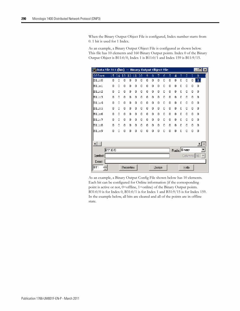
290 Micrologix 1400 Distributed Network Protocol (DNP3)
When the Binary Output Object File is configured, Index number starts from 0. 1 bit is used for 1 Index.
As an example, a Binary Output Object File is configured as shown below. This file has 10 elements and 160 Binary Output points. Index 0 of the Binary Output Object is B11:0/0, Index 1 is B11:0/1 and Index 159 is B11:9/15.
As an example, a Binary Output Config File shown below has 10 elements. Each bit can be configured for Online information (if the corresponding point is active or not, 0=offline, 1=online) of the Binary Output points. B31:0/0 is for Index 0, B31:0/1 is for Index 1 and B31:9/15 is for Index 159. In the example below, all bits are cleared and all of the points are in offline state.
Publication 1766-UM001F-EN-P - March 2011
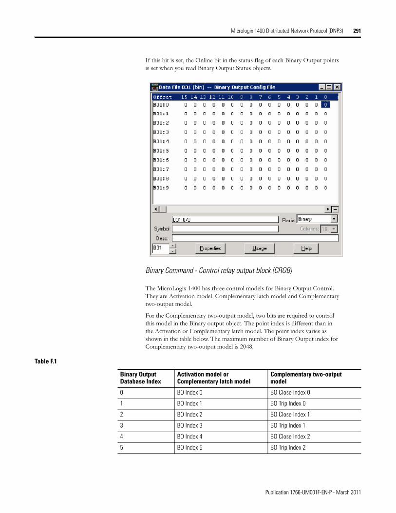
Micrologix 1400 Distributed Network Protocol (DNP3) 291
If this bit is set, the Online bit in the status flag of each Binary Output points is set when you read Binary Output Status objects.
Binary Command - Control relay output block (CROB)
The MicroLogix 1400 has three control models for Binary Output Control. They are Activation model, Complementary latch model and Complementary two-output model.
For the Complementary two-output model, two bits are required to control this model in the Binary output object. The point index is different than in the Activation or Complementary latch model. The point index varies as shown in the table below. The maximum number of Binary Output index for Complementary two-output model is 2048.
Table F.1
Binary Output Database Index
Activation model or Complementary latch model
Complementary two-output model
0 BO Index 0 BO Close Index 0
1 BO Index 1 BO Trip Index 0
2 BO Index 2 BO Close Index 1
3 BO Index 3 BO Trip Index 1
4 BO Index 4 BO Close Index 2
5 BO Index 5 BO Trip Index 2
Publication 1766-UM001F-EN-P - March 2011
292 Micrologix 1400 Distributed Network Protocol (DNP3)
These control codes and point models are implemented in the MicroLogix 1400 controller:
• 0x00 (NUL/NUL): Clear field Off
• 0x20 (NUL/NUL): Clear field On
• 0x01 (Pulse On/NUL): Clear field Off, Activation Model
• 0x21 (Pulse On/NUL): Clear field On, Activation Model
• 0x03 (Latch On/NUL): Clear field Off, Complementary latch model
• 0x23 (Latch On/NUL): Clear field On, Complementary latch model
• 0x04 (Latch Off/NUL): Clear field Off, Complementary latch model
• 0x24 (Latch Off/NUL): Clear field On, Complementary latch model
• 0x41 (Pulse On/Close): Clear field Off, Complementary two-output model
• 0x61 (Pulse On/Close): Clear field On, Complementary two-output model
• 0x81 (Pulse On/Trip): Clear field Off, Complementary two-output model
• 0xA1 (Pulse On/Trip): Clear field On, Complementary two-output model
When the MicroLogix 1400 is in Non-Executing mode, the controller will not accept a Binary Command. The MicroLogix 1400 returns a Control Status Code 7 in response. To access objects 12(CROB), the controller should be in Executing mode.
Note that Executing mode includes Run, Remote Run, Test Continuous Scan, and Test Single Scan modes. Any others are Non-Executing modes.
DNP3 Double Bit Binary Input Object
The supported object group and variations are listed in this section. The MicroLogix 1400 responds with the default group and variation when the DNP3 Master requests to read an object with Any variation.
Double-bit Binary Input Static Objects:
• g3v0 - Double-bit Binary Input - All Variations
• g3v1 - Double-bit Binary Input - Packed format (default)
• g3v2 - Double-bit Binary Input - With flags
… … …
4094 BO Index 4094 BO Close Index 2047
4095 BO Index 4095 BO Trip Index 2047
Table F.1
Binary Output Database Index
Activation model or Complementary latch model
Complementary two-output model
Publication 1766-UM001F-EN-P - March 2011
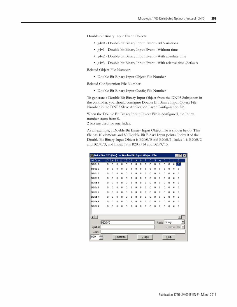
Micrologix 1400 Distributed Network Protocol (DNP3) 293
Double-bit Binary Input Event Objects:
• g4v0 - Double-bit Binary Input Event - All Variations
• g4v1 - Double-bit Binary Input Event - Without time
• g4v2 - Double-bit Binary Input Event - With absolute time
• g4v3 - Double-bit Binary Input Event - With relative time (default)
Related Object File Number:
• Double Bit Binary Input Object File Number
Related Configuration File Number:
• Double Bit Binary Input Config File Number
To generate a Double Bit Binary Input Object from the DNP3 Subsystem in the controller, you should configure Double Bit Binary Input Object File Number in the DNP3 Slave Application Layer Configuration file.
When the Double Bit Binary Input Object File is configured, the Index number starts from 0.2 bits are used for one Index.
As an example, a Double Bit Binary Input Object File is shown below. This file has 10 elements and 80 Double Bit Binary Input points. Index 0 of the Double Bit Binary Input Object is B20:0/0 and B20:0/1, Index 1 is B20:0/2 and B20:0/3, and Index 79 is B20:9/14 and B20:9/15.
Publication 1766-UM001F-EN-P - March 2011
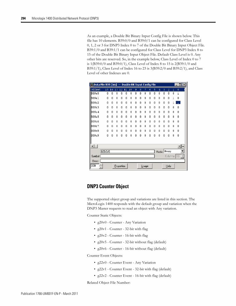
294 Micrologix 1400 Distributed Network Protocol (DNP3)
As an example, a Double Bit Binary Input Config File is shown below. This file has 10 elements. B39:0/0 and B39:0/1 can be configured for Class Level 0, 1, 2 or 3 for DNP3 Index 0 to 7 of the Double Bit Binary Input Object File. B39:1/0 and B39:1/1 can be configured for Class Level for DNP3 Index 8 to 15 of the Double Bit Binary Input Object File. Default Class Level is 0. Any other bits are reserved. So, in the example below, Class Level of Index 0 to 7 is 1(B39:0/0 and B39:0/1), Class Level of Index 8 to 15 is 2(B39:1/0 and B39:1/1), Class Level of Index 16 to 23 is 3(B39:2/0 and B39:2/1), and Class Level of other Indexes are 0.
DNP3 Counter Object
The supported object group and variations are listed in this section. The MicroLogix 1400 responds with the default group and variation when the DNP3 Master requests to read an object with Any variation.
Counter Static Objects:
• g20v0 - Counter - Any Variation
• g20v1 - Counter - 32-bit with flag
• g20v2 - Counter - 16-bit with flag
• g20v5 - Counter - 32-bit without flag (default)
• g20v6 - Counter - 16-bit without flag (default)
Counter Event Objects:
• g22v0 - Counter Event - Any Variation
• g22v1 - Counter Event - 32-bit with flag (default)
• g22v2 - Counter Event - 16-bit with flag (default)
Related Object File Number:
Publication 1766-UM001F-EN-P - March 2011
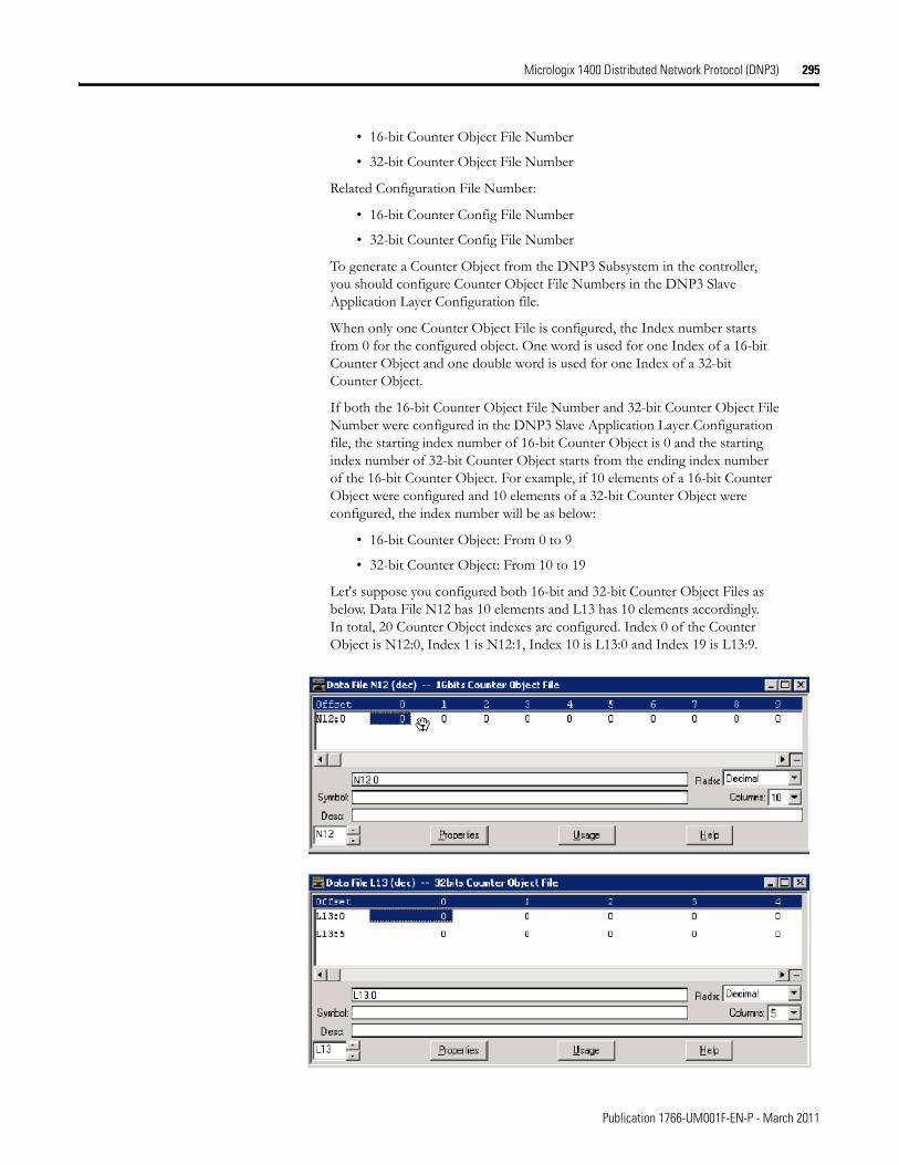
Micrologix 1400 Distributed Network Protocol (DNP3) 295
• 16-bit Counter Object File Number
• 32-bit Counter Object File Number
Related Configuration File Number:
• 16-bit Counter Config File Number
• 32-bit Counter Config File Number
To generate a Counter Object from the DNP3 Subsystem in the controller, you should configure Counter Object File Numbers in the DNP3 Slave Application Layer Configuration file.
When only one Counter Object File is configured, the Index number starts from 0 for the configured object. One word is used for one Index of a 16-bit Counter Object and one double word is used for one Index of a 32-bit Counter Object.
If both the 16-bit Counter Object File Number and 32-bit Counter Object File Number were configured in the DNP3 Slave Application Layer Configuration file, the starting index number of 16-bit Counter Object is 0 and the starting index number of 32-bit Counter Object starts from the ending index number of the 16-bit Counter Object. For example, if 10 elements of a 16-bit Counter Object were configured and 10 elements of a 32-bit Counter Object were configured, the index number will be as below:
• 16-bit Counter Object: From 0 to 9
• 32-bit Counter Object: From 10 to 19
Let's suppose you configured both 16-bit and 32-bit Counter Object Files as below. Data File N12 has 10 elements and L13 has 10 elements accordingly. In total, 20 Counter Object indexes are configured. Index 0 of the Counter Object is N12:0, Index 1 is N12:1, Index 10 is L13:0 and Index 19 is L13:9.
Publication 1766-UM001F-EN-P - March 2011
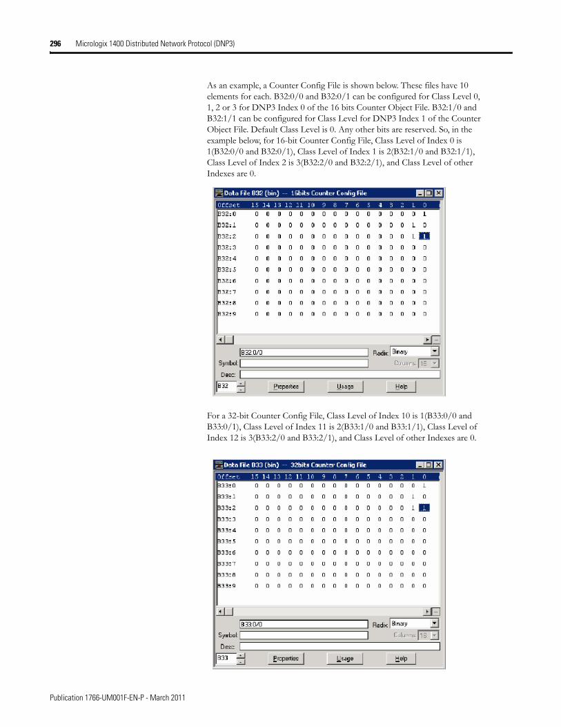
296 Micrologix 1400 Distributed Network Protocol (DNP3)
As an example, a Counter Config File is shown below. These files have 10 elements for each. B32:0/0 and B32:0/1 can be configured for Class Level 0, 1, 2 or 3 for DNP3 Index 0 of the 16 bits Counter Object File. B32:1/0 and B32:1/1 can be configured for Class Level for DNP3 Index 1 of the Counter Object File. Default Class Level is 0. Any other bits are reserved. So, in the example below, for 16-bit Counter Config File, Class Level of Index 0 is 1(B32:0/0 and B32:0/1), Class Level of Index 1 is 2(B32:1/0 and B32:1/1), Class Level of Index 2 is 3(B32:2/0 and B32:2/1), and Class Level of other Indexes are 0.
For a 32-bit Counter Config File, Class Level of Index 10 is 1(B33:0/0 and B33:0/1), Class Level of Index 11 is 2(B33:1/0 and B33:1/1), Class Level of Index 12 is 3(B33:2/0 and B33:2/1), and Class Level of other Indexes are 0.
Publication 1766-UM001F-EN-P - March 2011
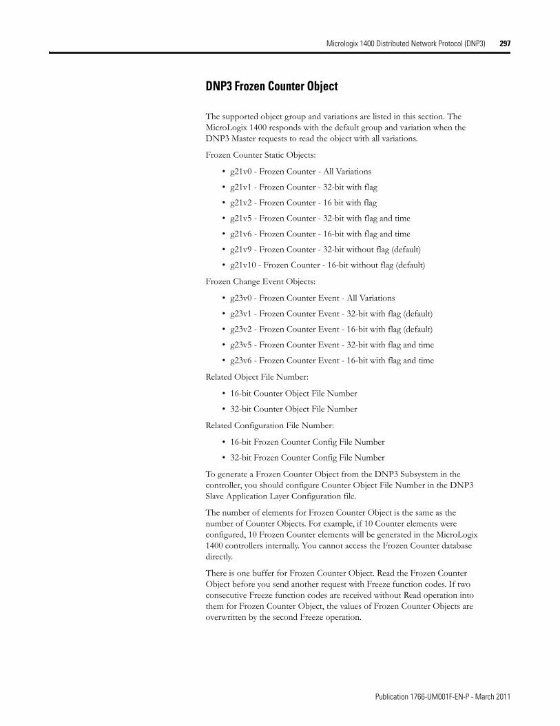
Micrologix 1400 Distributed Network Protocol (DNP3) 297
DNP3 Frozen Counter Object
The supported object group and variations are listed in this section. The MicroLogix 1400 responds with the default group and variation when the DNP3 Master requests to read the object with all variations.
Frozen Counter Static Objects:
• g21v0 - Frozen Counter - All Variations
• g21v1 - Frozen Counter - 32-bit with flag
• g21v2 - Frozen Counter - 16 bit with flag
• g21v5 - Frozen Counter - 32-bit with flag and time
• g21v6 - Frozen Counter - 16-bit with flag and time
• g21v9 - Frozen Counter - 32-bit without flag (default)
• g21v10 - Frozen Counter - 16-bit without flag (default)
Frozen Change Event Objects:
• g23v0 - Frozen Counter Event - All Variations
• g23v1 - Frozen Counter Event - 32-bit with flag (default)
• g23v2 - Frozen Counter Event - 16-bit with flag (default)
• g23v5 - Frozen Counter Event - 32-bit with flag and time
• g23v6 - Frozen Counter Event - 16-bit with flag and time
Related Object File Number:
• 16-bit Counter Object File Number
• 32-bit Counter Object File Number
Related Configuration File Number:
• 16-bit Frozen Counter Config File Number
• 32-bit Frozen Counter Config File Number
To generate a Frozen Counter Object from the DNP3 Subsystem in the controller, you should configure Counter Object File Number in the DNP3 Slave Application Layer Configuration file.
The number of elements for Frozen Counter Object is the same as the number of Counter Objects. For example, if 10 Counter elements were configured, 10 Frozen Counter elements will be generated in the MicroLogix 1400 controllers internally. You cannot access the Frozen Counter database directly.
There is one buffer for Frozen Counter Object. Read the Frozen Counter Object before you send another request with Freeze function codes. If two consecutive Freeze function codes are received without Read operation into them for Frozen Counter Object, the values of Frozen Counter Objects are overwritten by the second Freeze operation.
Publication 1766-UM001F-EN-P - March 2011
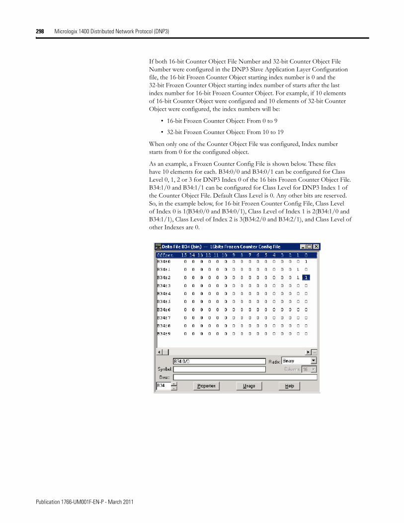
298 Micrologix 1400 Distributed Network Protocol (DNP3)
If both 16-bit Counter Object File Number and 32-bit Counter Object File Number were configured in the DNP3 Slave Application Layer Configuration file, the 16-bit Frozen Counter Object starting index number is 0 and the 32-bit Frozen Counter Object starting index number of starts after the last index number for 16-bit Frozen Counter Object. For example, if 10 elements of 16-bit Counter Object were configured and 10 elements of 32-bit Counter Object were configured, the index numbers will be:
• 16-bit Frozen Counter Object: From 0 to 9
• 32-bit Frozen Counter Object: From 10 to 19
When only one of the Counter Object File was configured, Index number starts from 0 for the configured object.
As an example, a Frozen Counter Config File is shown below. These files have 10 elements for each. B34:0/0 and B34:0/1 can be configured for Class Level 0, 1, 2 or 3 for DNP3 Index 0 of the 16 bits Frozen Counter Object File. B34:1/0 and B34:1/1 can be configured for Class Level for DNP3 Index 1 of the Counter Object File. Default Class Level is 0. Any other bits are reserved. So, in the example below, for 16-bit Frozen Counter Config File, Class Level of Index 0 is 1(B34:0/0 and B34:0/1), Class Level of Index 1 is 2(B34:1/0 and B34:1/1), Class Level of Index 2 is 3(B34:2/0 and B34:2/1), and Class Level of other Indexes are 0.
Publication 1766-UM001F-EN-P - March 2011
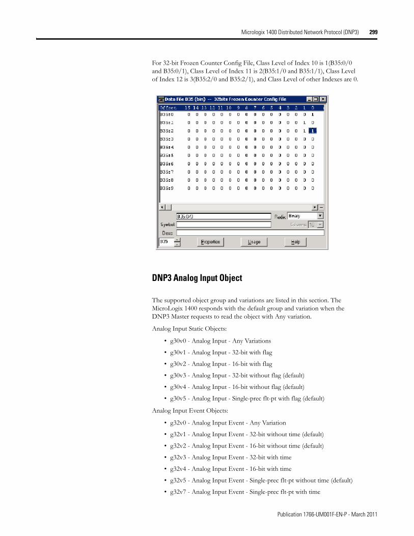
Micrologix 1400 Distributed Network Protocol (DNP3) 299
For 32-bit Frozen Counter Config File, Class Level of Index 10 is 1(B35:0/0 and B35:0/1), Class Level of Index 11 is 2(B35:1/0 and B35:1/1), Class Level of Index 12 is 3(B35:2/0 and B35:2/1), and Class Level of other Indexes are 0.
DNP3 Analog Input Object
The supported object group and variations are listed in this section. The MicroLogix 1400 responds with the default group and variation when the DNP3 Master requests to read the object with Any variation.
Analog Input Static Objects:
• g30v0 - Analog Input - Any Variations
• g30v1 - Analog Input - 32-bit with flag
• g30v2 - Analog Input - 16-bit with flag
• g30v3 - Analog Input - 32-bit without flag (default)
• g30v4 - Analog Input - 16-bit without flag (default)
• g30v5 - Analog Input - Single-prec flt-pt with flag (default)
Analog Input Event Objects:
• g32v0 - Analog Input Event - Any Variation
• g32v1 - Analog Input Event - 32-bit without time (default)
• g32v2 - Analog Input Event - 16-bit without time (default)
• g32v3 - Analog Input Event - 32-bit with time
• g32v4 - Analog Input Event - 16-bit with time
• g32v5 - Analog Input Event - Single-prec flt-pt without time (default)
• g32v7 - Analog Input Event - Single-prec flt-pt with time
Publication 1766-UM001F-EN-P - March 2011
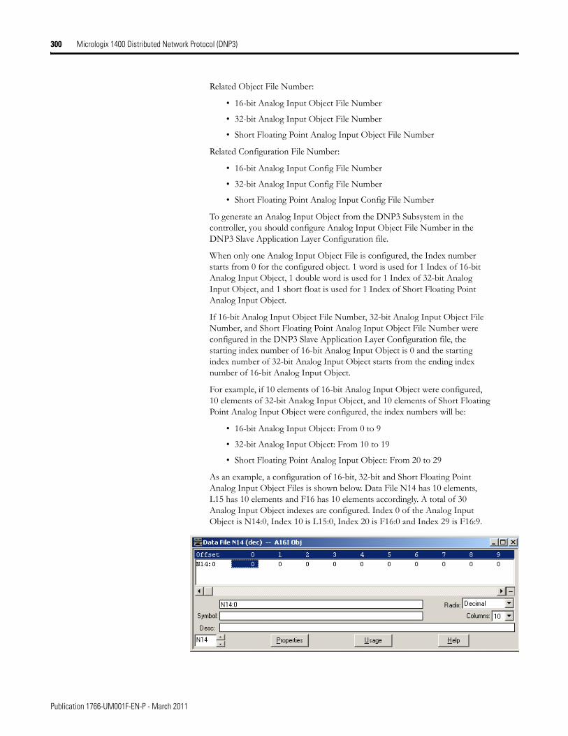
300 Micrologix 1400 Distributed Network Protocol (DNP3)
Related Object File Number:
• 16-bit Analog Input Object File Number
• 32-bit Analog Input Object File Number
• Short Floating Point Analog Input Object File Number
Related Configuration File Number:
• 16-bit Analog Input Config File Number
• 32-bit Analog Input Config File Number
• Short Floating Point Analog Input Config File Number
To generate an Analog Input Object from the DNP3 Subsystem in the controller, you should configure Analog Input Object File Number in the DNP3 Slave Application Layer Configuration file.
When only one Analog Input Object File is configured, the Index number starts from 0 for the configured object. 1 word is used for 1 Index of 16-bit Analog Input Object, 1 double word is used for 1 Index of 32-bit Analog Input Object, and 1 short float is used for 1 Index of Short Floating Point Analog Input Object.
If 16-bit Analog Input Object File Number, 32-bit Analog Input Object File Number, and Short Floating Point Analog Input Object File Number were configured in the DNP3 Slave Application Layer Configuration file, the starting index number of 16-bit Analog Input Object is 0 and the starting index number of 32-bit Analog Input Object starts from the ending index number of 16-bit Analog Input Object.
For example, if 10 elements of 16-bit Analog Input Object were configured, 10 elements of 32-bit Analog Input Object, and 10 elements of Short Floating Point Analog Input Object were configured, the index numbers will be:
• 16-bit Analog Input Object: From 0 to 9
• 32-bit Analog Input Object: From 10 to 19
• Short Floating Point Analog Input Object: From 20 to 29
As an example, a configuration of 16-bit, 32-bit and Short Floating Point Analog Input Object Files is shown below. Data File N14 has 10 elements, L15 has 10 elements and F16 has 10 elements accordingly. A total of 30 Analog Input Object indexes are configured. Index 0 of the Analog Input Object is N14:0, Index 10 is L15:0, Index 20 is F16:0 and Index 29 is F16:9.
Publication 1766-UM001F-EN-P - March 2011
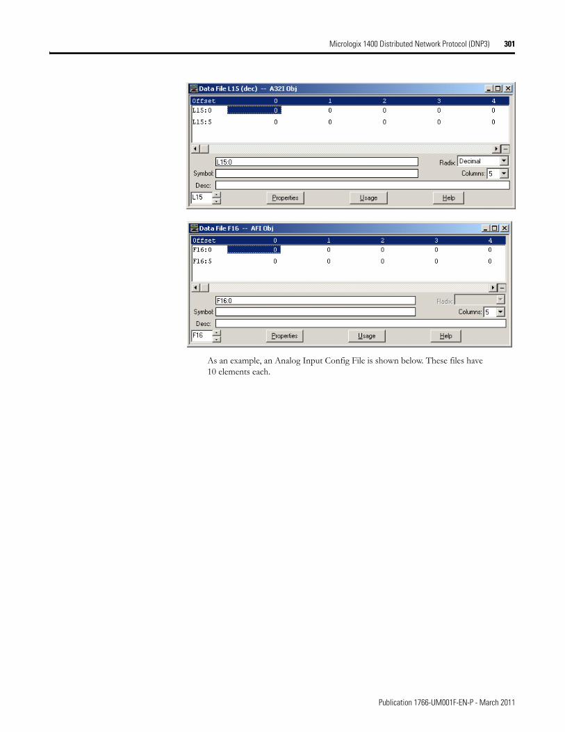
Micrologix 1400 Distributed Network Protocol (DNP3) 301
As an example, an Analog Input Config File is shown below. These files have 10 elements each.
Publication 1766-UM001F-EN-P - March 2011
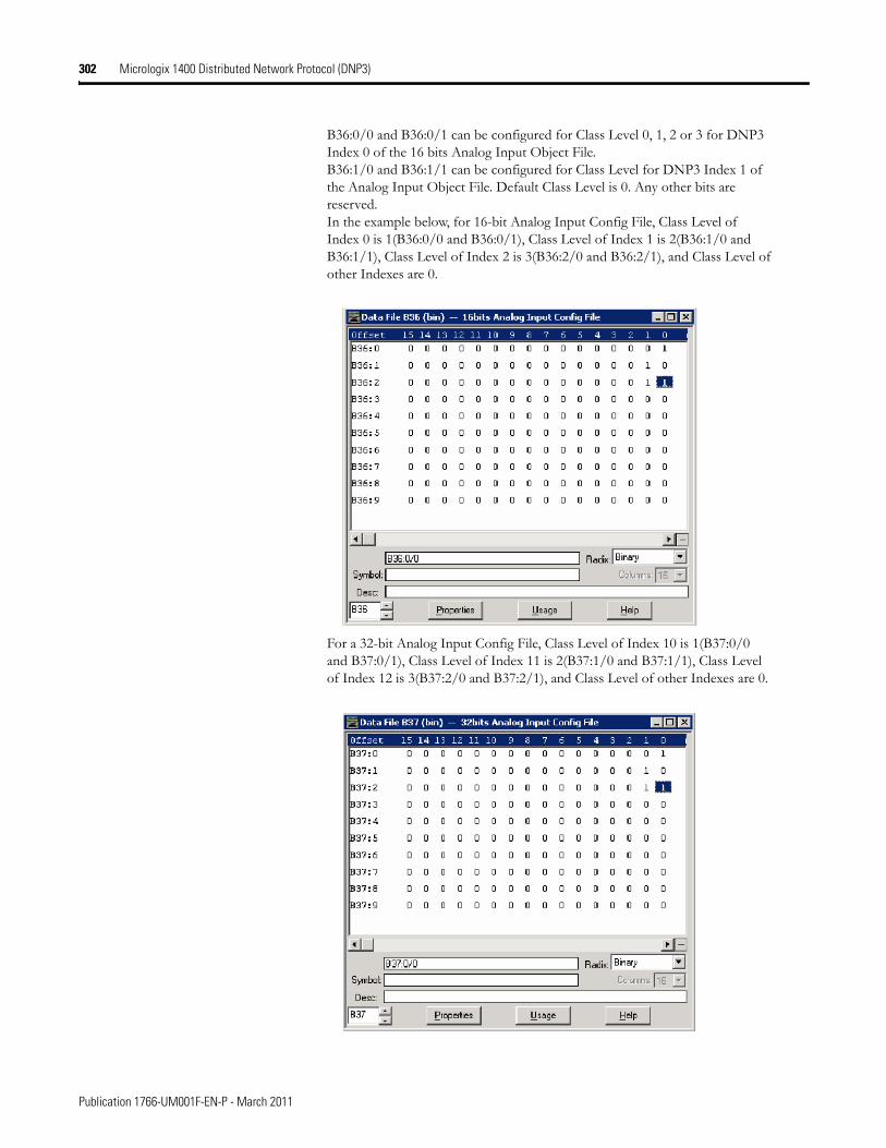
302 Micrologix 1400 Distributed Network Protocol (DNP3)
B36:0/0 and B36:0/1 can be configured for Class Level 0, 1, 2 or 3 for DNP3 Index 0 of the 16 bits Analog Input Object File. B36:1/0 and B36:1/1 can be configured for Class Level for DNP3 Index 1 of the Analog Input Object File. Default Class Level is 0. Any other bits are reserved. In the example below, for 16-bit Analog Input Config File, Class Level of Index 0 is 1(B36:0/0 and B36:0/1), Class Level of Index 1 is 2(B36:1/0 and B36:1/1), Class Level of Index 2 is 3(B36:2/0 and B36:2/1), and Class Level of other Indexes are 0.
For a 32-bit Analog Input Config File, Class Level of Index 10 is 1(B37:0/0 and B37:0/1), Class Level of Index 11 is 2(B37:1/0 and B37:1/1), Class Level of Index 12 is 3(B37:2/0 and B37:2/1), and Class Level of other Indexes are 0.
Publication 1766-UM001F-EN-P - March 2011
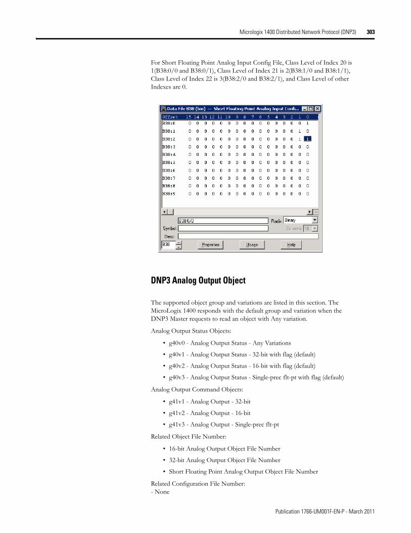
Micrologix 1400 Distributed Network Protocol (DNP3) 303
For Short Floating Point Analog Input Config File, Class Level of Index 20 is 1(B38:0/0 and B38:0/1), Class Level of Index 21 is 2(B38:1/0 and B38:1/1), Class Level of Index 22 is 3(B38:2/0 and B38:2/1), and Class Level of other Indexes are 0.
DNP3 Analog Output Object
The supported object group and variations are listed in this section. The MicroLogix 1400 responds with the default group and variation when the DNP3 Master requests to read an object with Any variation.
Analog Output Status Objects:
• g40v0 - Analog Output Status - Any Variations
• g40v1 - Analog Output Status - 32-bit with flag (default)
• g40v2 - Analog Output Status - 16-bit with flag (default)
• g40v3 - Analog Output Status - Single-prec flt-pt with flag (default)
Analog Output Command Objects:
• g41v1 - Analog Output - 32-bit
• g41v2 - Analog Output - 16-bit
• g41v3 - Analog Output - Single-prec flt-pt
Related Object File Number:
• 16-bit Analog Output Object File Number
• 32-bit Analog Output Object File Number
• Short Floating Point Analog Output Object File Number
Related Configuration File Number:- None
Publication 1766-UM001F-EN-P - March 2011
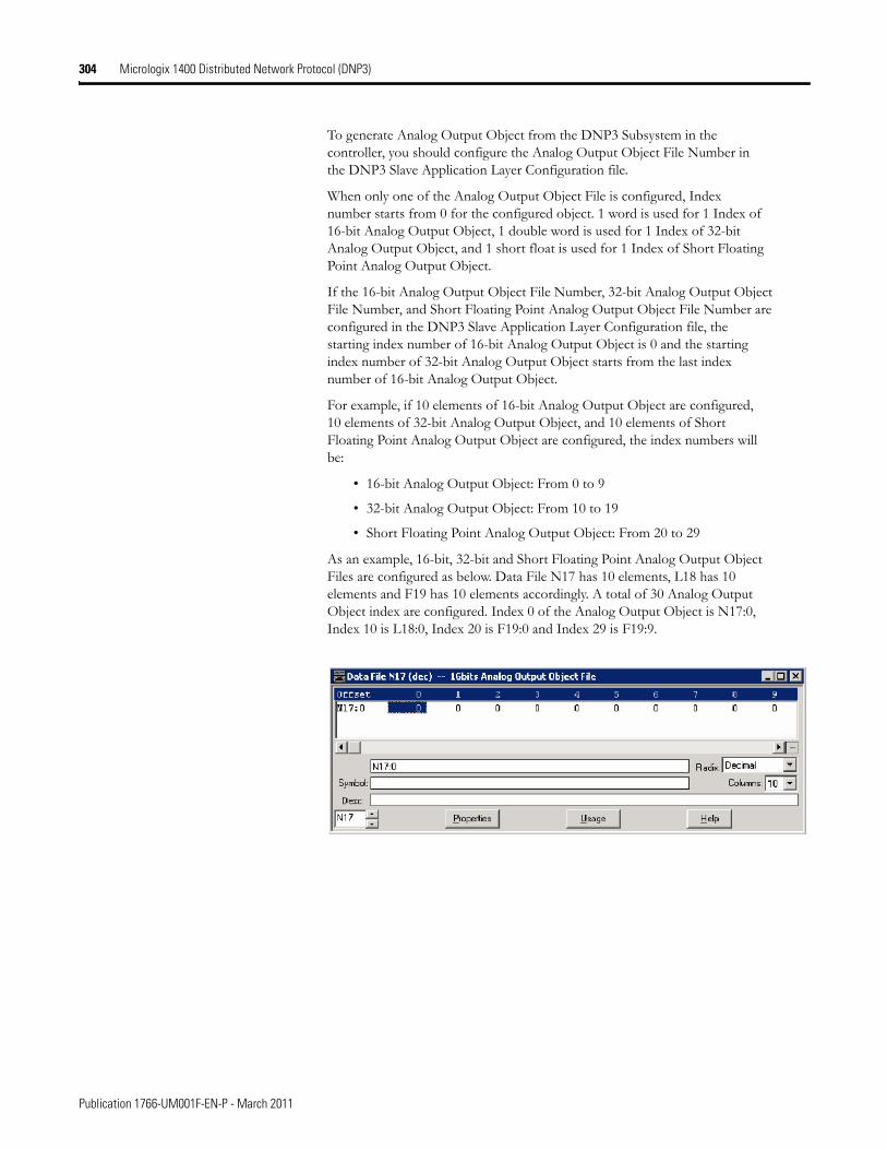
304 Micrologix 1400 Distributed Network Protocol (DNP3)
To generate Analog Output Object from the DNP3 Subsystem in the controller, you should configure the Analog Output Object File Number in the DNP3 Slave Application Layer Configuration file.
When only one of the Analog Output Object File is configured, Index number starts from 0 for the configured object. 1 word is used for 1 Index of 16-bit Analog Output Object, 1 double word is used for 1 Index of 32-bit Analog Output Object, and 1 short float is used for 1 Index of Short Floating Point Analog Output Object.
If the 16-bit Analog Output Object File Number, 32-bit Analog Output Object File Number, and Short Floating Point Analog Output Object File Number are configured in the DNP3 Slave Application Layer Configuration file, the starting index number of 16-bit Analog Output Object is 0 and the starting index number of 32-bit Analog Output Object starts from the last index number of 16-bit Analog Output Object.
For example, if 10 elements of 16-bit Analog Output Object are configured, 10 elements of 32-bit Analog Output Object, and 10 elements of Short Floating Point Analog Output Object are configured, the index numbers will be:
• 16-bit Analog Output Object: From 0 to 9
• 32-bit Analog Output Object: From 10 to 19
• Short Floating Point Analog Output Object: From 20 to 29
As an example, 16-bit, 32-bit and Short Floating Point Analog Output Object Files are configured as below. Data File N17 has 10 elements, L18 has 10 elements and F19 has 10 elements accordingly. A total of 30 Analog Output Object index are configured. Index 0 of the Analog Output Object is N17:0, Index 10 is L18:0, Index 20 is F19:0 and Index 29 is F19:9.
Publication 1766-UM001F-EN-P - March 2011
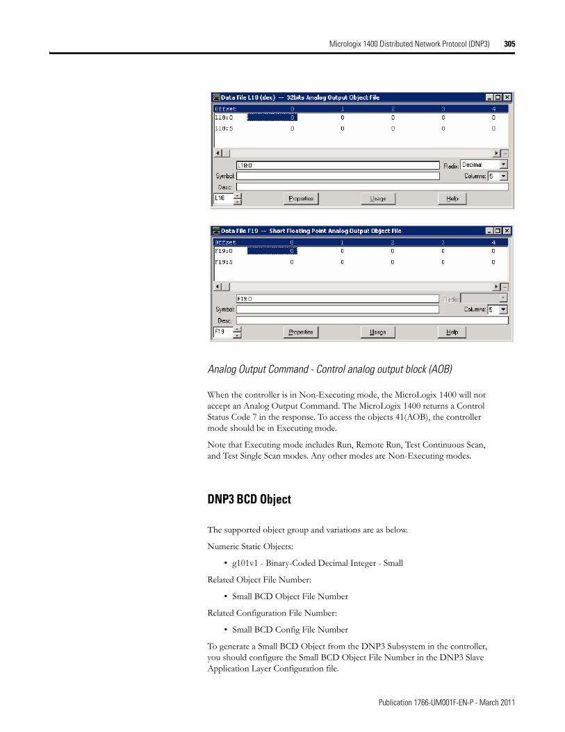
Micrologix 1400 Distributed Network Protocol (DNP3) 305
Analog Output Command - Control analog output block (AOB)
When the controller is in Non-Executing mode, the MicroLogix 1400 will not accept an Analog Output Command. The MicroLogix 1400 returns a Control Status Code 7 in the response. To access the objects 41(AOB), the controller mode should be in Executing mode.
Note that Executing mode includes Run, Remote Run, Test Continuous Scan, and Test Single Scan modes. Any other modes are Non-Executing modes.
DNP3 BCD Object
The supported object group and variations are as below.
Numeric Static Objects:
• g101v1 - Binary-Coded Decimal Integer - Small
Related Object File Number:
• Small BCD Object File Number
Related Configuration File Number:
• Small BCD Config File Number
To generate a Small BCD Object from the DNP3 Subsystem in the controller, you should configure the Small BCD Object File Number in the DNP3 Slave Application Layer Configuration file.
Publication 1766-UM001F-EN-P - March 2011
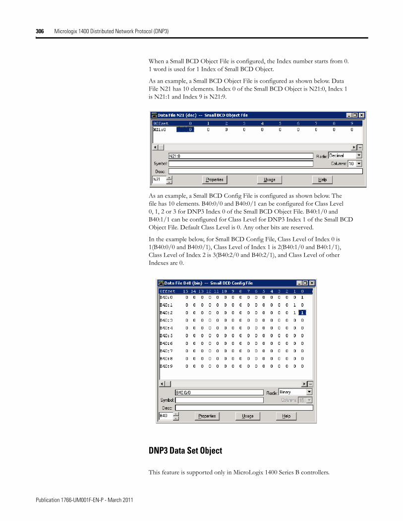
306 Micrologix 1400 Distributed Network Protocol (DNP3)
When a Small BCD Object File is configured, the Index number starts from 0. 1 word is used for 1 Index of Small BCD Object.
As an example, a Small BCD Object File is configured as shown below. Data File N21 has 10 elements. Index 0 of the Small BCD Object is N21:0, Index 1 is N21:1 and Index 9 is N21:9.
As an example, a Small BCD Config File is configured as shown below. The file has 10 elements. B40:0/0 and B40:0/1 can be configured for Class Level 0, 1, 2 or 3 for DNP3 Index 0 of the Small BCD Object File. B40:1/0 and B40:1/1 can be configured for Class Level for DNP3 Index 1 of the Small BCD Object File. Default Class Level is 0. Any other bits are reserved.
In the example below, for Small BCD Config File, Class Level of Index 0 is 1(B40:0/0 and B40:0/1), Class Level of Index 1 is 2(B40:1/0 and B40:1/1), Class Level of Index 2 is 3(B40:2/0 and B40:2/1), and Class Level of other Indexes are 0.
DNP3 Data Set Object
This feature is supported only in MicroLogix 1400 Series B controllers.
Publication 1766-UM001F-EN-P - March 2011
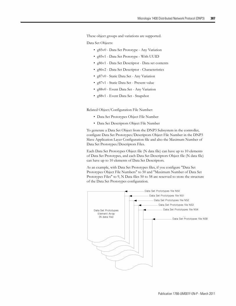
Micrologix 1400 Distributed Network Protocol (DNP3) 307
These object groups and variations are supported.
Data Set Objects:
• g85v0 - Data Set Prototype - Any Variation
• g85v1 - Data Set Prototype - With UUID
• g86v1 - Data Set Descriptor - Data set contents
• g86v2 - Data Set Descriptor - Characteristics
• g87v0 - Static Data Set - Any Variation
• g87v1 - Static Data Set - Present value
• g88v0 - Event Data Set - Any Variation
• g88v1 - Event Data Set - Snapshot
Related Object/Configuration File Number:
• Data Set Prototypes Object File Number
• Data Set Descriptors Object File Number
To generate a Data Set Object from the DNP3 Subsystem in the controller, configure Data Set Prototypes/Descriptors Object File Number in the DNP3 Slave Application Layer Configuration file and also the Maximum Number of Data Set Prototypes/Descriptors Files.
Each Data Set Prototypes Object file (N data file) can have up to 10 elements of Data Set Prototypes, and each Data Set Descriptors Object file (N data file) can have up to 10 elements of Data Set Descriptors.
As an example, with Data Set Prototypes files, if you configure "Data Set Prototypes Object File Numbers" to 50 and "Maximum Number of Data Set Prototypes Files" to 9, N Data files 50 to 58 are reserved to store the structure of the Data Set Prototypes configuration.
Data Set Prototypes file N50
Data Set Prototypes
Element Array(N data file)
Data Set Prototypes file N51
Data Set Prototypes file N52
Data Set Prototypes file N53
Data Set Prototypes file N54
Data Set Prototypes file N58...
Publication 1766-UM001F-EN-P - March 2011
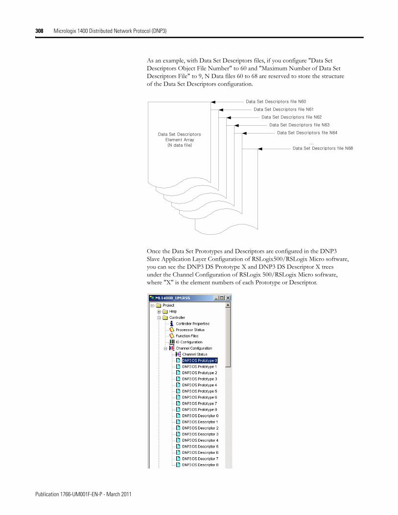
308 Micrologix 1400 Distributed Network Protocol (DNP3)
As an example, with Data Set Descriptors files, if you configure "Data Set Descriptors Object File Number" to 60 and "Maximum Number of Data Set Descriptors File" to 9, N Data files 60 to 68 are reserved to store the structure of the Data Set Descriptors configuration.
Once the Data Set Prototypes and Descriptors are configured in the DNP3 Slave Application Layer Configuration of RSLogix500/RSLogix Micro software, you can see the DNP3 DS Prototype X and DNP3 DS Descriptor X trees under the Channel Configuration of RSLogix 500/RSLogix Micro software, where "X" is the element numbers of each Prototype or Descriptor.
Data Set Descriptors file N60
Data Set Descriptors
Element Array(N data file)
Data Set Descriptors file N61
Data Set Descriptors file N62
Data Set Descriptors file N63
Data Set Descriptors file N64
Data Set Descriptors file N68...
Publication 1766-UM001F-EN-P - March 2011
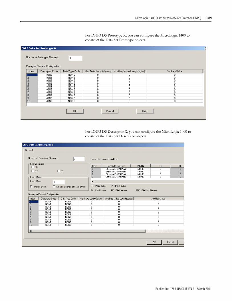
Micrologix 1400 Distributed Network Protocol (DNP3) 309
For DNP3 DS Prototype X, you can configure the MicroLogix 1400 to construct the Data Set Prototype objects.
For DNP3 DS Descriptor X, you can configure the MicroLogix 1400 to construct the Data Set Descriptor objects.
Publication 1766-UM001F-EN-P - March 2011
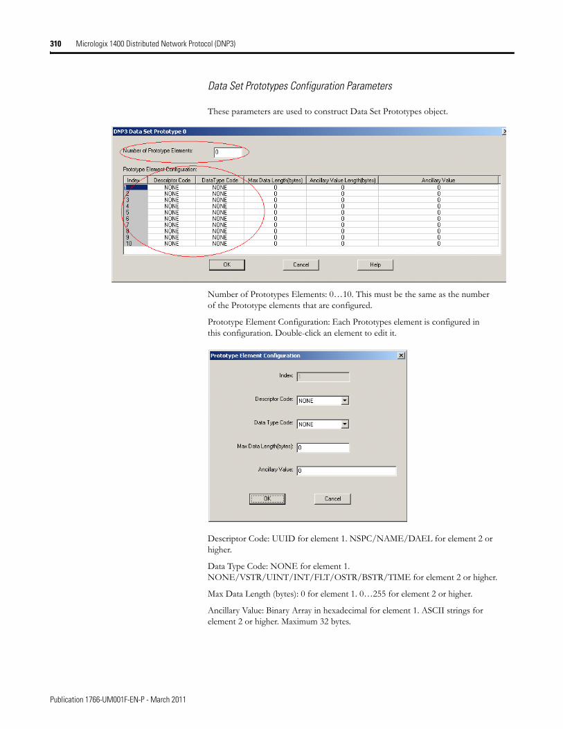
310 Micrologix 1400 Distributed Network Protocol (DNP3)
Data Set Prototypes Configuration Parameters
These parameters are used to construct Data Set Prototypes object.
Number of Prototypes Elements: 0…10. This must be the same as the number of the Prototype elements that are configured.
Prototype Element Configuration: Each Prototypes element is configured in this configuration. Double-click an element to edit it.
Descriptor Code: UUID for element 1. NSPC/NAME/DAEL for element 2 or higher.
Data Type Code: NONE for element 1. NONE/VSTR/UINT/INT/FLT/OSTR/BSTR/TIME for element 2 or higher.
Max Data Length (bytes): 0 for element 1. 0…255 for element 2 or higher.
Ancillary Value: Binary Array in hexadecimal for element 1. ASCII strings for element 2 or higher. Maximum 32 bytes.
Publication 1766-UM001F-EN-P - March 2011
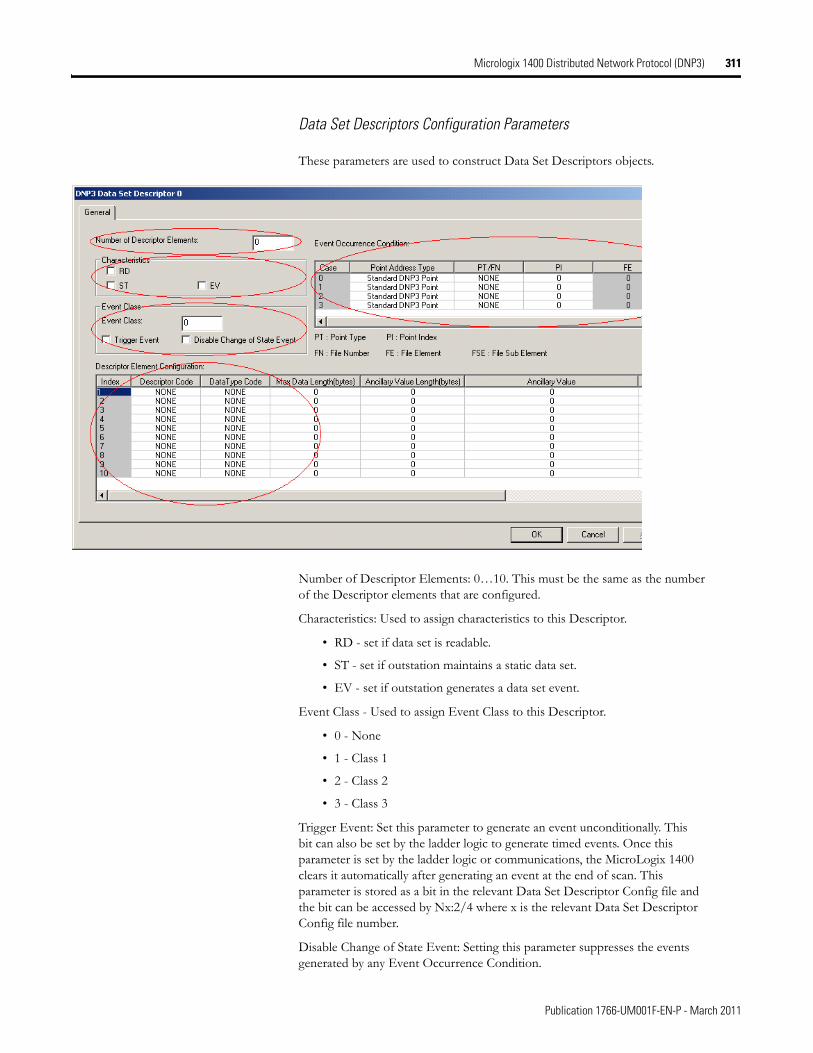
Micrologix 1400 Distributed Network Protocol (DNP3) 311
Data Set Descriptors Configuration Parameters
These parameters are used to construct Data Set Descriptors objects.
Number of Descriptor Elements: 0…10. This must be the same as the number of the Descriptor elements that are configured.
Characteristics: Used to assign characteristics to this Descriptor.
• RD - set if data set is readable.
• ST - set if outstation maintains a static data set.
• EV - set if outstation generates a data set event.
Event Class - Used to assign Event Class to this Descriptor.
• 0 - None
• 1 - Class 1
• 2 - Class 2
• 3 - Class 3
Trigger Event: Set this parameter to generate an event unconditionally. This bit can also be set by the ladder logic to generate timed events. Once this parameter is set by the ladder logic or communications, the MicroLogix 1400 clears it automatically after generating an event at the end of scan. This parameter is stored as a bit in the relevant Data Set Descriptor Config file and the bit can be accessed by Nx:2/4 where x is the relevant Data Set Descriptor Config file number.
Disable Change of State Event: Setting this parameter suppresses the events generated by any Event Occurrence Condition.
Publication 1766-UM001F-EN-P - March 2011
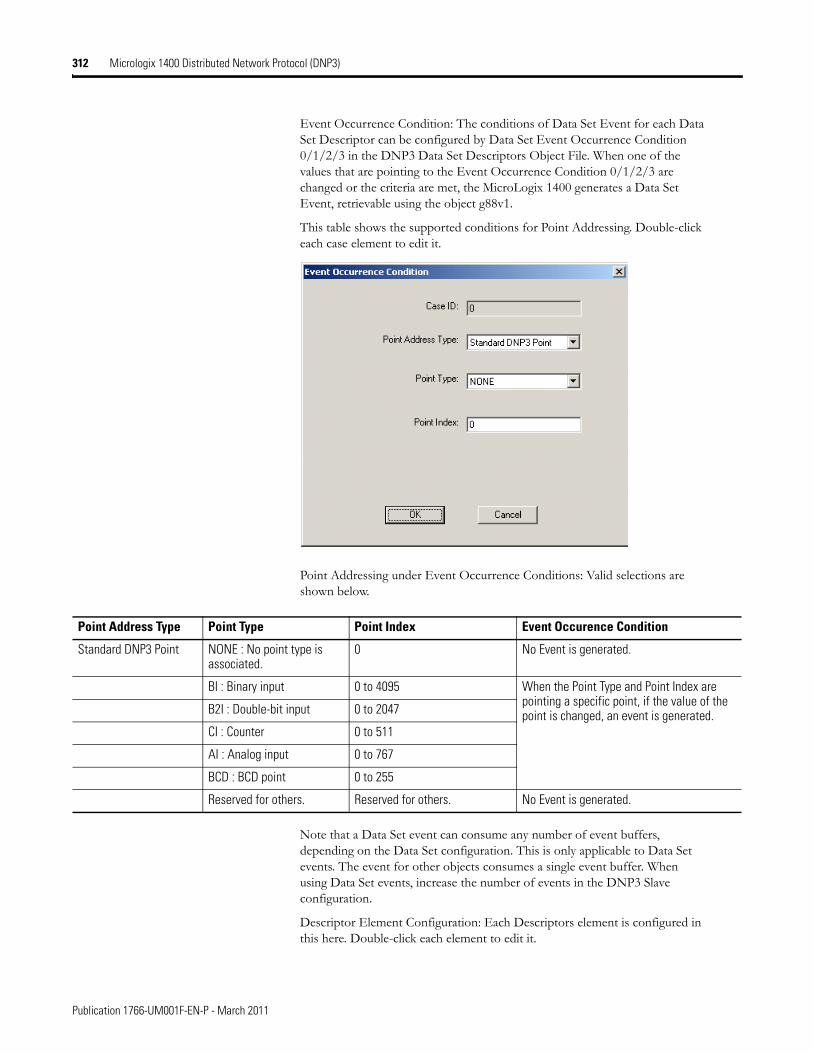
312 Micrologix 1400 Distributed Network Protocol (DNP3)
Event Occurrence Condition: The conditions of Data Set Event for each Data Set Descriptor can be configured by Data Set Event Occurrence Condition 0/1/2/3 in the DNP3 Data Set Descriptors Object File. When one of the values that are pointing to the Event Occurrence Condition 0/1/2/3 are changed or the criteria are met, the MicroLogix 1400 generates a Data Set Event, retrievable using the object g88v1.
This table shows the supported conditions for Point Addressing. Double-click each case element to edit it.
Point Addressing under Event Occurrence Conditions: Valid selections are shown below.
Note that a Data Set event can consume any number of event buffers, depending on the Data Set configuration. This is only applicable to Data Set events. The event for other objects consumes a single event buffer. When using Data Set events, increase the number of events in the DNP3 Slave configuration.
Descriptor Element Configuration: Each Descriptors element is configured in this here. Double-click each element to edit it.
Point Address Type Point Type Point Index Event Occurence Condition
Standard DNP3 Point NONE : No point type is associated.
0 No Event is generated.
BI : Binary input 0 to 4095 When the Point Type and Point Index are pointing a specific point, if the value of the point is changed, an event is generated.B2I : Double-bit input 0 to 2047
CI : Counter 0 to 511
AI : Analog input 0 to 767
BCD : BCD point 0 to 255
Reserved for others. Reserved for others. No Event is generated.
Publication 1766-UM001F-EN-P - March 2011
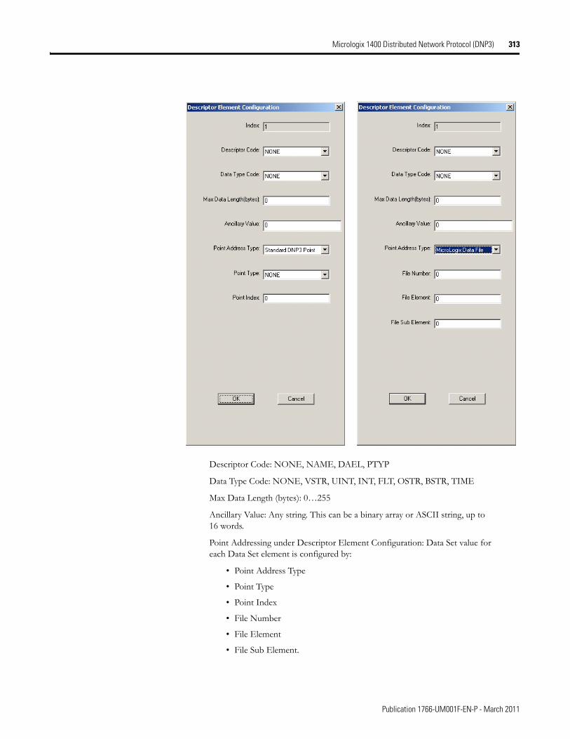
Micrologix 1400 Distributed Network Protocol (DNP3) 313
Descriptor Code: NONE, NAME, DAEL, PTYP
Data Type Code: NONE, VSTR, UINT, INT, FLT, OSTR, BSTR, TIME
Max Data Length (bytes): 0…255
Ancillary Value: Any string. This can be a binary array or ASCII string, up to 16 words.
Point Addressing under Descriptor Element Configuration: Data Set value for each Data Set element is configured by:
• Point Address Type
• Point Type
• Point Index
• File Number
• File Element
• File Sub Element.
Publication 1766-UM001F-EN-P - March 2011
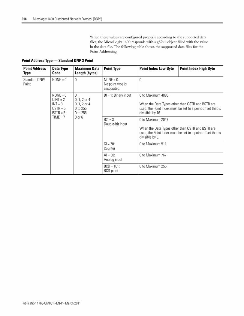
314 Micrologix 1400 Distributed Network Protocol (DNP3)
When these values are configured properly according to the supported data files, the MicroLogix 1400 responds with a g87v1 object filled with the value in the data file. The following table shows the supported data files for the Point Addressing.
Point Address Type — Standard DNP 3 Point
Point Address Type
Data Type Code
Maximum Data Length (bytes)
Point Type Point Index Low Byte Point Index High Byte
Standard DNP3 Point
NONE = 0 0 NONE = 0: No point type is associated.
0
NONE = 0UINT = 2INT = 3OSTR = 5BSTR = 6TIME = 7
00, 1, 2 or 40, 1, 2 or 40 to 2550 to 2550 or 6
BI = 1: Binary input 0 to Maximum 4095
When the Data Types other than OSTR and BSTR are used, the Point Index must be set to a point offset that is divisible by 16.
B2I = 3:Double-bit input
0 to Maximum 2047
When the Data Types other than OSTR and BSTR are used, the Point Index must be set to a point offset that is divisible by 8.
CI = 20:Counter
0 to Maximum 511
AI = 30:Analog input
0 to Maximum 767
BCD = 101: BCD point
0 to Maximum 255
Publication 1766-UM001F-EN-P - March 2011
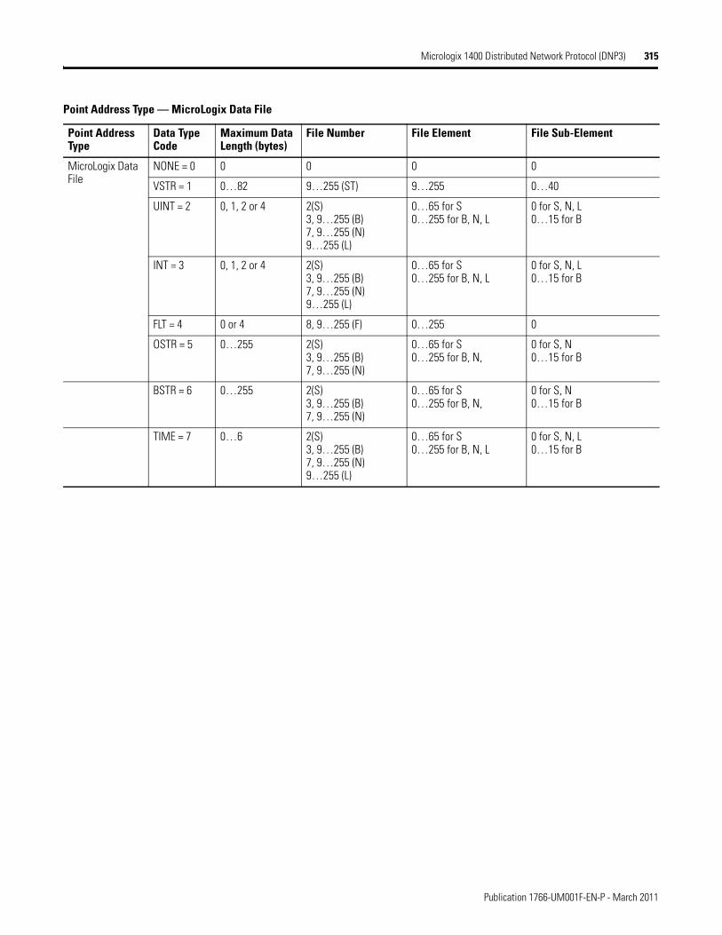
Micrologix 1400 Distributed Network Protocol (DNP3) 315
Point Address Type — MicroLogix Data File
Point Address Type
Data Type Code
Maximum Data Length (bytes)
File Number File Element File Sub-Element
MicroLogix Data File
NONE = 0 0 0 0 0
VSTR = 1 0…82 9…255 (ST) 9…255 0…40
UINT = 2 0, 1, 2 or 4 2(S)3, 9…255 (B)7, 9…255 (N)9…255 (L)
0…65 for S0…255 for B, N, L
0 for S, N, L0…15 for B
INT = 3 0, 1, 2 or 4 2(S)3, 9…255 (B)7, 9…255 (N)9…255 (L)
0…65 for S0…255 for B, N, L
0 for S, N, L0…15 for B
FLT = 4 0 or 4 8, 9…255 (F) 0…255 0
OSTR = 5 0…255 2(S)3, 9…255 (B)7, 9…255 (N)
0…65 for S0…255 for B, N,
0 for S, N0…15 for B
BSTR = 6 0…255 2(S)3, 9…255 (B)7, 9…255 (N)
0…65 for S0…255 for B, N,
0 for S, N0…15 for B
TIME = 7 0…6 2(S)3, 9…255 (B)7, 9…255 (N)9…255 (L)
0…65 for S0…255 for B, N, L
0 for S, N, L0…15 for B
Publication 1766-UM001F-EN-P - March 2011
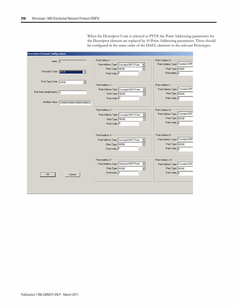
316 Micrologix 1400 Distributed Network Protocol (DNP3)
When the Descriptor Code is selected as PTYP, the Point Addressing parameters for the Descriptor element are replaced by 10 Point Addressing parameters. These should be configured in the same order of the DAEL elements in the relevant Prototypes.
Publication 1766-UM001F-EN-P - March 2011
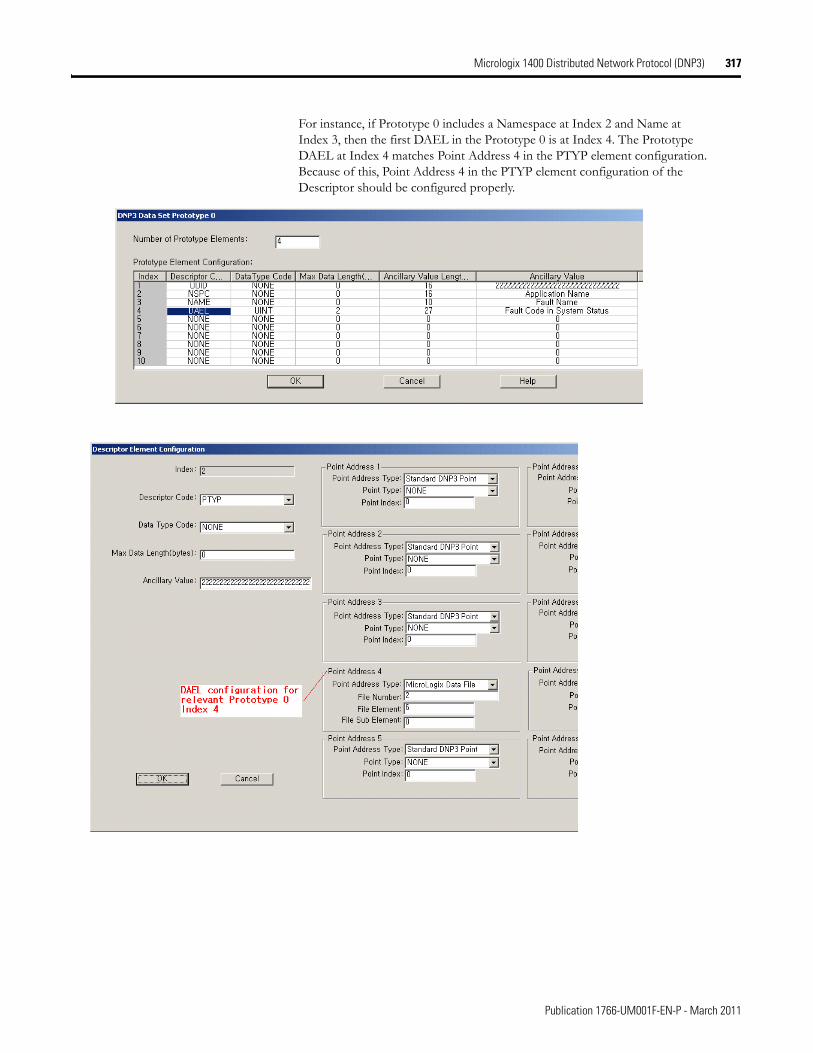
Micrologix 1400 Distributed Network Protocol (DNP3) 317
For instance, if Prototype 0 includes a Namespace at Index 2 and Name at Index 3, then the first DAEL in the Prototype 0 is at Index 4. The Prototype DAEL at Index 4 matches Point Address 4 in the PTYP element configuration. Because of this, Point Address 4 in the PTYP element configuration of the Descriptor should be configured properly.
Publication 1766-UM001F-EN-P - March 2011
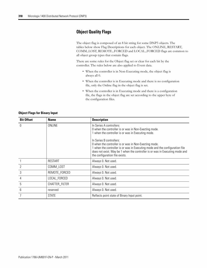
318 Micrologix 1400 Distributed Network Protocol (DNP3)
Object Quality Flags
The object flag is composed of an 8 bit string for some DNP3 objects. The tables below show Flag Descriptions for each object. The ONLINE, RESTART, COMM_LOST, REMOTE_FORCED and LOCAL_FORCED flags are common to all object group types that contain flags.
There are some rules for the Object flag set or clear for each bit by the controller. The rules below are also applied to Event data.
• When the controller is in Non-Executing mode, the object flag is always all 0.
• When the controller is in Executing mode and there is no configuration file, only the Online flag in the object flag is set.
• When the controller is in Executing mode and there is a configuration file, the flags in the object flag are set according to the upper byte of the configuration files.
Object Flags for Binary Input
Bit Offset Name Description
0 ONLINE In Series A controllers:0 when the controller is or was in Non-Execting mode.1 when the controller is or was in Executing mode.
In Series B controllers:0 when the controller is or was in Non-Execting mode.1 when the controller is or was in Executing mode and the configuration file does not exist. May be 1 when the controller is or was in Executing mode and the configuration file exists.
1 RESTART Always 0. Not used.
2 COMM_LOST Always 0. Not used.
3 REMOTE_FORCED Always 0. Not used.
4 LOCAL_FORCED Always 0. Not used.
5 CHATTER_FILTER Always 0. Not used.
6 reserved Always 0. Not used.
7 STATE Reflects point state of Binary Input point.
Publication 1766-UM001F-EN-P - March 2011
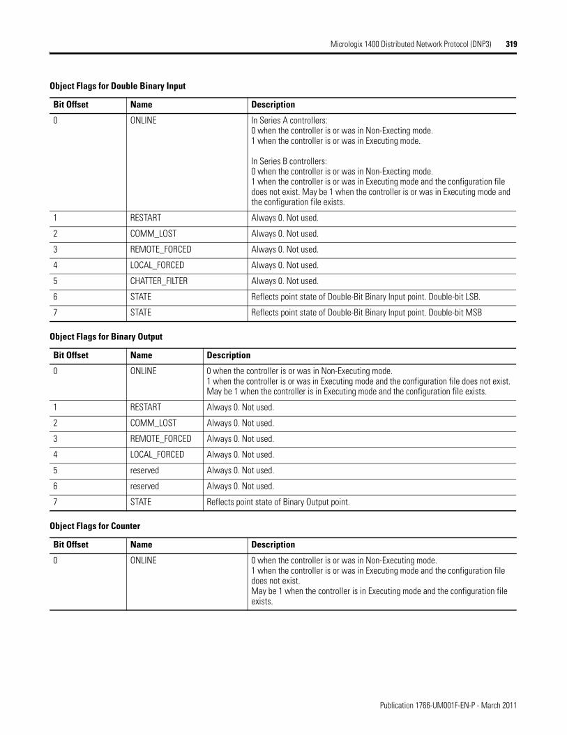
Micrologix 1400 Distributed Network Protocol (DNP3) 319
Object Flags for Double Binary Input
Bit Offset Name Description
0 ONLINE In Series A controllers:0 when the controller is or was in Non-Execting mode.1 when the controller is or was in Executing mode.
In Series B controllers:0 when the controller is or was in Non-Execting mode.1 when the controller is or was in Executing mode and the configuration file does not exist. May be 1 when the controller is or was in Executing mode and the configuration file exists.
1 RESTART Always 0. Not used.
2 COMM_LOST Always 0. Not used.
3 REMOTE_FORCED Always 0. Not used.
4 LOCAL_FORCED Always 0. Not used.
5 CHATTER_FILTER Always 0. Not used.
6 STATE Reflects point state of Double-Bit Binary Input point. Double-bit LSB.
7 STATE Reflects point state of Double-Bit Binary Input point. Double-bit MSB
Object Flags for Binary Output
Bit Offset Name Description
0 ONLINE 0 when the controller is or was in Non-Executing mode.1 when the controller is or was in Executing mode and the configuration file does not exist. May be 1 when the controller is in Executing mode and the configuration file exists.
1 RESTART Always 0. Not used.
2 COMM_LOST Always 0. Not used.
3 REMOTE_FORCED Always 0. Not used.
4 LOCAL_FORCED Always 0. Not used.
5 reserved Always 0. Not used.
6 reserved Always 0. Not used.
7 STATE Reflects point state of Binary Output point.
Object Flags for Counter
Bit Offset Name Description
0 ONLINE 0 when the controller is or was in Non-Executing mode.1 when the controller is or was in Executing mode and the configuration file does not exist. May be 1 when the controller is in Executing mode and the configuration file exists.
Publication 1766-UM001F-EN-P - March 2011
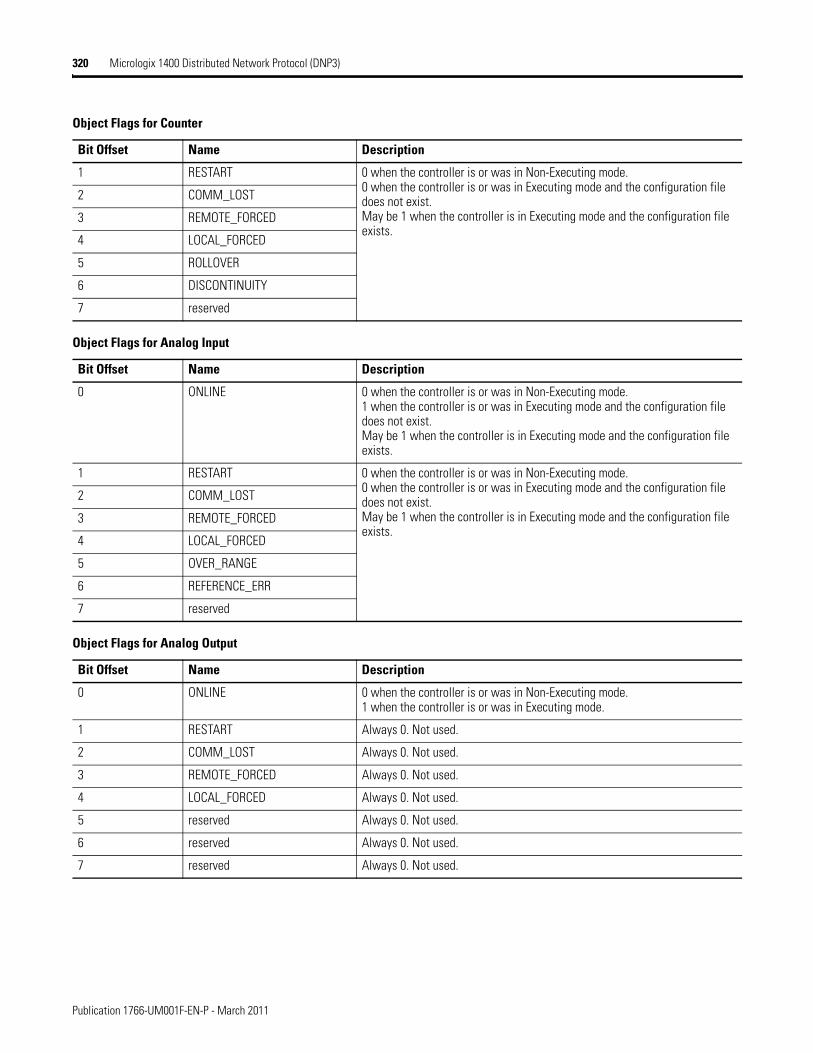
320 Micrologix 1400 Distributed Network Protocol (DNP3)
1 RESTART 0 when the controller is or was in Non-Executing mode.0 when the controller is or was in Executing mode and the configuration file does not exist. May be 1 when the controller is in Executing mode and the configuration file exists.
2 COMM_LOST
3 REMOTE_FORCED
4 LOCAL_FORCED
5 ROLLOVER
6 DISCONTINUITY
7 reserved
Object Flags for Analog Input
Bit Offset Name Description
0 ONLINE 0 when the controller is or was in Non-Executing mode.1 when the controller is or was in Executing mode and the configuration file does not exist. May be 1 when the controller is in Executing mode and the configuration file exists.
1 RESTART 0 when the controller is or was in Non-Executing mode.0 when the controller is or was in Executing mode and the configuration file does not exist. May be 1 when the controller is in Executing mode and the configuration file exists.
2 COMM_LOST
3 REMOTE_FORCED
4 LOCAL_FORCED
5 OVER_RANGE
6 REFERENCE_ERR
7 reserved
Object Flags for Analog Output
Bit Offset Name Description
0 ONLINE 0 when the controller is or was in Non-Executing mode.1 when the controller is or was in Executing mode.
1 RESTART Always 0. Not used.
2 COMM_LOST Always 0. Not used.
3 REMOTE_FORCED Always 0. Not used.
4 LOCAL_FORCED Always 0. Not used.
5 reserved Always 0. Not used.
6 reserved Always 0. Not used.
7 reserved Always 0. Not used.
Object Flags for Counter
Bit Offset Name Description
Publication 1766-UM001F-EN-P - March 2011
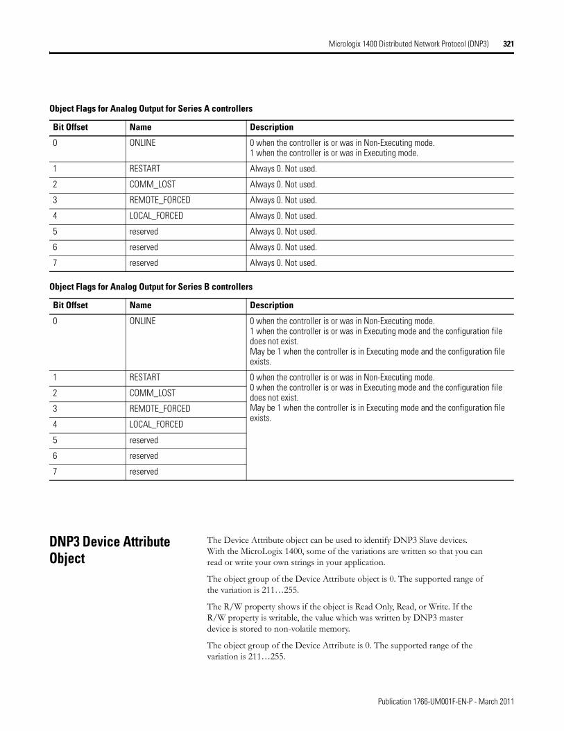
Micrologix 1400 Distributed Network Protocol (DNP3) 321
DNP3 Device Attribute Object
The Device Attribute object can be used to identify DNP3 Slave devices. With the MicroLogix 1400, some of the variations are written so that you can read or write your own strings in your application.
The object group of the Device Attribute object is 0. The supported range of the variation is 211…255.
The R/W property shows if the object is Read Only, Read, or Write. If the R/W property is writable, the value which was written by DNP3 master device is stored to non-volatile memory.
The object group of the Device Attribute is 0. The supported range of the variation is 211…255.
Object Flags for Analog Output for Series A controllers
Bit Offset Name Description
0 ONLINE 0 when the controller is or was in Non-Executing mode.1 when the controller is or was in Executing mode.
1 RESTART Always 0. Not used.
2 COMM_LOST Always 0. Not used.
3 REMOTE_FORCED Always 0. Not used.
4 LOCAL_FORCED Always 0. Not used.
5 reserved Always 0. Not used.
6 reserved Always 0. Not used.
7 reserved Always 0. Not used.
Object Flags for Analog Output for Series B controllers
Bit Offset Name Description
0 ONLINE 0 when the controller is or was in Non-Executing mode.1 when the controller is or was in Executing mode and the configuration file does not exist. May be 1 when the controller is in Executing mode and the configuration file exists.
1 RESTART 0 when the controller is or was in Non-Executing mode.0 when the controller is or was in Executing mode and the configuration file does not exist. May be 1 when the controller is in Executing mode and the configuration file exists.
2 COMM_LOST
3 REMOTE_FORCED
4 LOCAL_FORCED
5 reserved
6 reserved
7 reserved
Publication 1766-UM001F-EN-P - March 2011
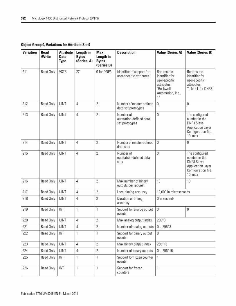
322 Micrologix 1400 Distributed Network Protocol (DNP3)
Object Group 0, Variations for Attribute Set 0
Variation Read /Write
Attribute Data Type
Length in Bytes (Series A)
Max Length in Bytes (Series B)
Description Value (Series A) Value (Series B)
211 Read Only VSTR 27 0 for DNP3 Identifier of support for user-specific attributes
Returns the identifier for user-specific attributes."Rockwell Automation, Inc., 1"
Returns the identifier for user-specific attributes."", NULL for DNP3.
212 Read Only UINT 4 2 Number of master-defined data set prototypes
0 0
213 Read Only UINT 4 2 Number of outstation-defined data set prototypes
0 The configured number in the DNP3 Slave Application Layer Configuration file.10, max
214 Read Only UINT 4 2 Number of master-defined data sets
0 0
215 Read Only UINT 4 2 Number of outstation-defined data sets
0 The configured number in the DNP3 Slave Application Layer Configuration file.10, max
216 Read Only UINT 4 2 Max number of binary outputs per request
10 10
217 Read Only UINT 4 2 Local timing accuracy 10,000 in microseconds
218 Read Only UINT 4 2 Duration of timing accuracy
0 in seconds
219 Read Only INT 1 1 Support for analog output events
0 0
220 Read Only UINT 4 2 Max analog output index 256*3
221 Read Only UINT 4 2 Number of analog outputs 0…256*3
222 Read Only INT 1 1 Support for binary output events
0
223 Read Only UINT 4 2 Max binary output index 256*16
224 Read Only UINT 4 2 Number of binary outputs 0…256*16
225 Read Only INT 1 1 Support for frozen counter events
1
226 Read Only INT 1 1 Support for frozen counters
1
Publication 1766-UM001F-EN-P - March 2011
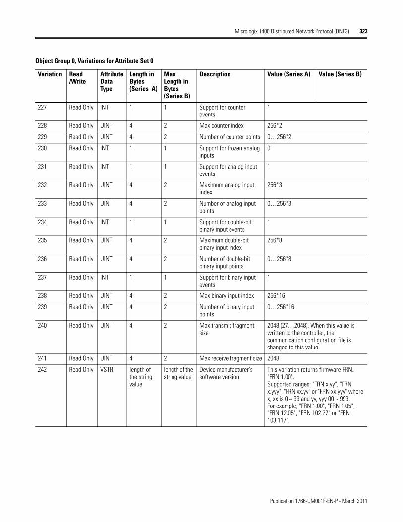
Micrologix 1400 Distributed Network Protocol (DNP3) 323
227 Read Only INT 1 1 Support for counter events
1
228 Read Only UINT 4 2 Max counter index 256*2
229 Read Only UINT 4 2 Number of counter points 0…256*2
230 Read Only INT 1 1 Support for frozen analog inputs
0
231 Read Only INT 1 1 Support for analog input events
1
232 Read Only UINT 4 2 Maximum analog input index
256*3
233 Read Only UINT 4 2 Number of analog input points
0…256*3
234 Read Only INT 1 1 Support for double-bit binary input events
1
235 Read Only UINT 4 2 Maximum double-bit binary input index
256*8
236 Read Only UINT 4 2 Number of double-bit binary input points
0…256*8
237 Read Only INT 1 1 Support for binary input events
1
238 Read Only UINT 4 2 Max binary input index 256*16
239 Read Only UINT 4 2 Number of binary input points
0…256*16
240 Read Only UINT 4 2 Max transmit fragment size
2048 (27…2048). When this value is written to the controller, the communication configuration file is changed to this value.
241 Read Only UINT 4 2 Max receive fragment size 2048
242 Read Only VSTR length of the string value
length of the string value
Device manufacturer's software version
This variation returns firmware FRN. "FRN 1.00".Supported ranges: "FRN x.yy", "FRN x.yyy", "FRN xx.yy" or "FRN xx.yyy" where x, xx is 0 ~ 99 and yy, yyy 00 ~ 999.For example, "FRN 1.00", "FRN 1.05", "FRN 12.05", "FRN 102.27" or "FRN 103.117".
Object Group 0, Variations for Attribute Set 0
Variation Read /Write
Attribute Data Type
Length in Bytes (Series A)
Max Length in Bytes (Series B)
Description Value (Series A) Value (Series B)
Publication 1766-UM001F-EN-P - March 2011
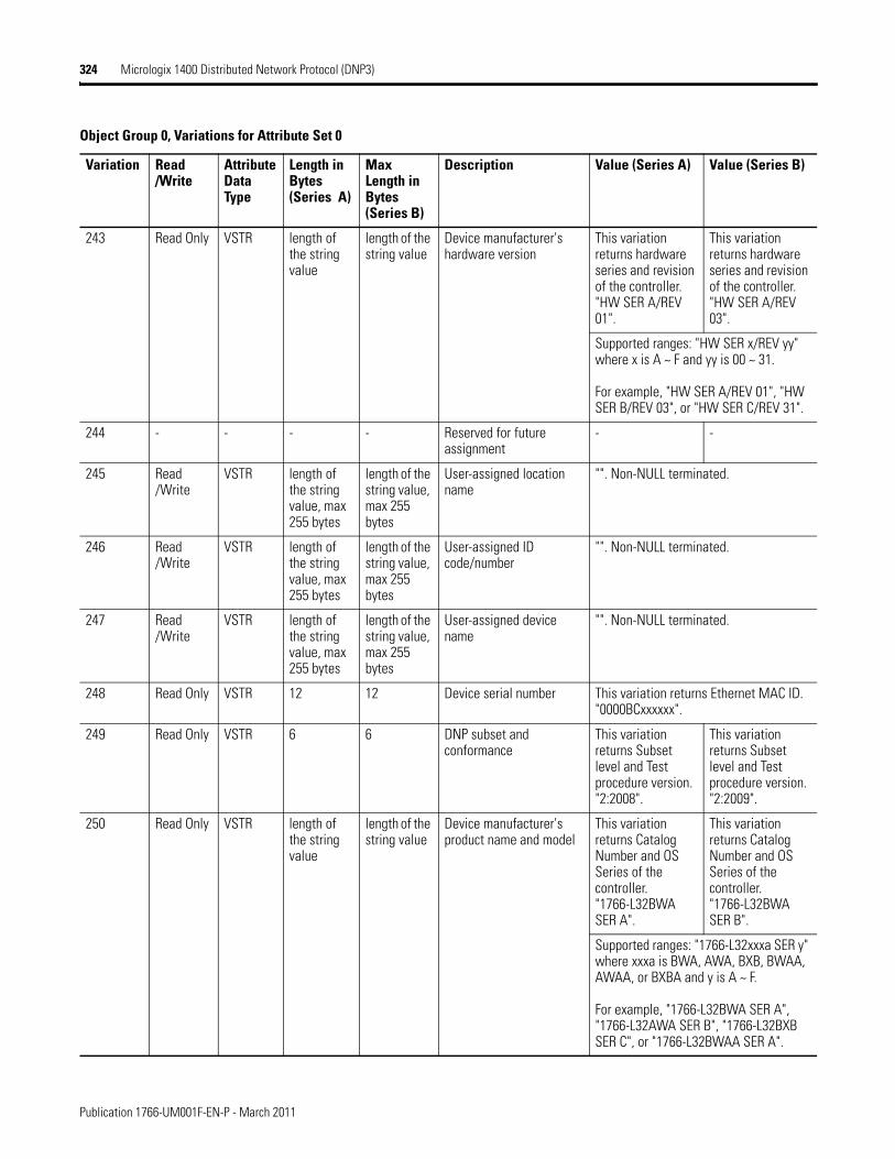
324 Micrologix 1400 Distributed Network Protocol (DNP3)
243 Read Only VSTR length of the string value
length of the string value
Device manufacturer's hardware version
This variation returns hardware series and revision of the controller. "HW SER A/REV 01".
This variation returns hardware series and revision of the controller. "HW SER A/REV 03".
Supported ranges: "HW SER x/REV yy" where x is A ~ F and yy is 00 ~ 31.
For example, "HW SER A/REV 01", "HW SER B/REV 03", or "HW SER C/REV 31".
244 - - - - Reserved for future assignment
- -
245 Read /Write
VSTR length of the string value, max 255 bytes
length of the string value, max 255 bytes
User-assigned location name
"". Non-NULL terminated.
246 Read /Write
VSTR length of the string value, max 255 bytes
length of the string value, max 255 bytes
User-assigned ID code/number
"". Non-NULL terminated.
247 Read /Write
VSTR length of the string value, max 255 bytes
length of the string value, max 255 bytes
User-assigned device name
"". Non-NULL terminated.
248 Read Only VSTR 12 12 Device serial number This variation returns Ethernet MAC ID. "0000BCxxxxxx".
249 Read Only VSTR 6 6 DNP subset and conformance
This variation returns Subset level and Test procedure version. "2:2008".
This variation returns Subset level and Test procedure version. "2:2009".
250 Read Only VSTR length of the string value
length of the string value
Device manufacturer's product name and model
This variation returns Catalog Number and OS Series of the controller. "1766-L32BWA SER A".
This variation returns Catalog Number and OS Series of the controller. "1766-L32BWA SER B".
Supported ranges: "1766-L32xxxa SER y" where xxxa is BWA, AWA, BXB, BWAA, AWAA, or BXBA and y is A ~ F.
For example, "1766-L32BWA SER A", "1766-L32AWA SER B", "1766-L32BXB SER C", or "1766-L32BWAA SER A".
Object Group 0, Variations for Attribute Set 0
Variation Read /Write
Attribute Data Type
Length in Bytes (Series A)
Max Length in Bytes (Series B)
Description Value (Series A) Value (Series B)
Publication 1766-UM001F-EN-P - March 2011
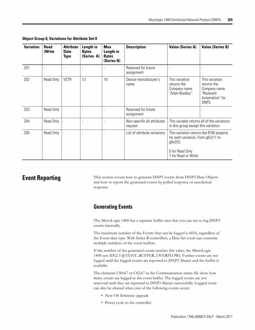
Micrologix 1400 Distributed Network Protocol (DNP3) 325
Event Reporting This section covers how to generate DNP3 events from DNP3 Data Objects and how to report the generated events by polled response or unsolicited response.
Generating Events
The MicroLogix 1400 has a separate buffer area that you can use to log DNP3 events internally.
The maximum number of the Events that can be logged is 6016, regardless of the Event data type. With Series B controllers, a Data Set event can consume multiple numbers of the event buffers.
If the number of the generated events reaches this value, the MicroLogix 1400 sets IIN2.3 [EVENT_BUFFER_OVERFLOW]. Further events are not logged until the logged events are reported to DNP3 Master and the buffer is available.
The elements CS0:67 or CS2:67 in the Communication status file show how many events are logged to the event buffer. The logged events are not removed until they are reported to DNP3 Master successfully. Logged event can also be cleared when one of the following events occur:
• New OS firmware upgrade
• Power cycle to the controller
251 - - - - Reserved for future assignment
- -
252 Read Only VSTR 13 19 Device manufacturer's name
This variation returns the Company name. "Allen-Bradley".
This variation returns the Company name. "Rockwell Automation" for DNP3.
253 Read Only - - - Reserved for future assignment
- -
254 Read Only - - - Non-specific all attributes request
This variable returns all of the variations in this group except this variation.
255 Read Only - - - List of attribute variations This variation returns the R/W property for each variation. From g0v211 to g0v253.
0 for Read Only1 for Read or Write
Object Group 0, Variations for Attribute Set 0
Variation Read /Write
Attribute Data Type
Length in Bytes (Series A)
Max Length in Bytes (Series B)
Description Value (Series A) Value (Series B)
Publication 1766-UM001F-EN-P - March 2011
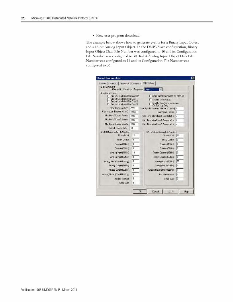
326 Micrologix 1400 Distributed Network Protocol (DNP3)
• New user program download.
The example below shows how to generate events for a Binary Input Object and a 16-bit Analog Input Object. In the DNP3 Slave configuration, Binary Input Object Data File Number was configured to 10 and its Configuration File Number was configured to 30. 16-bit Analog Input Object Data File Number was configured to 14 and its Configuration File Number was configured to 36.
Publication 1766-UM001F-EN-P - March 2011
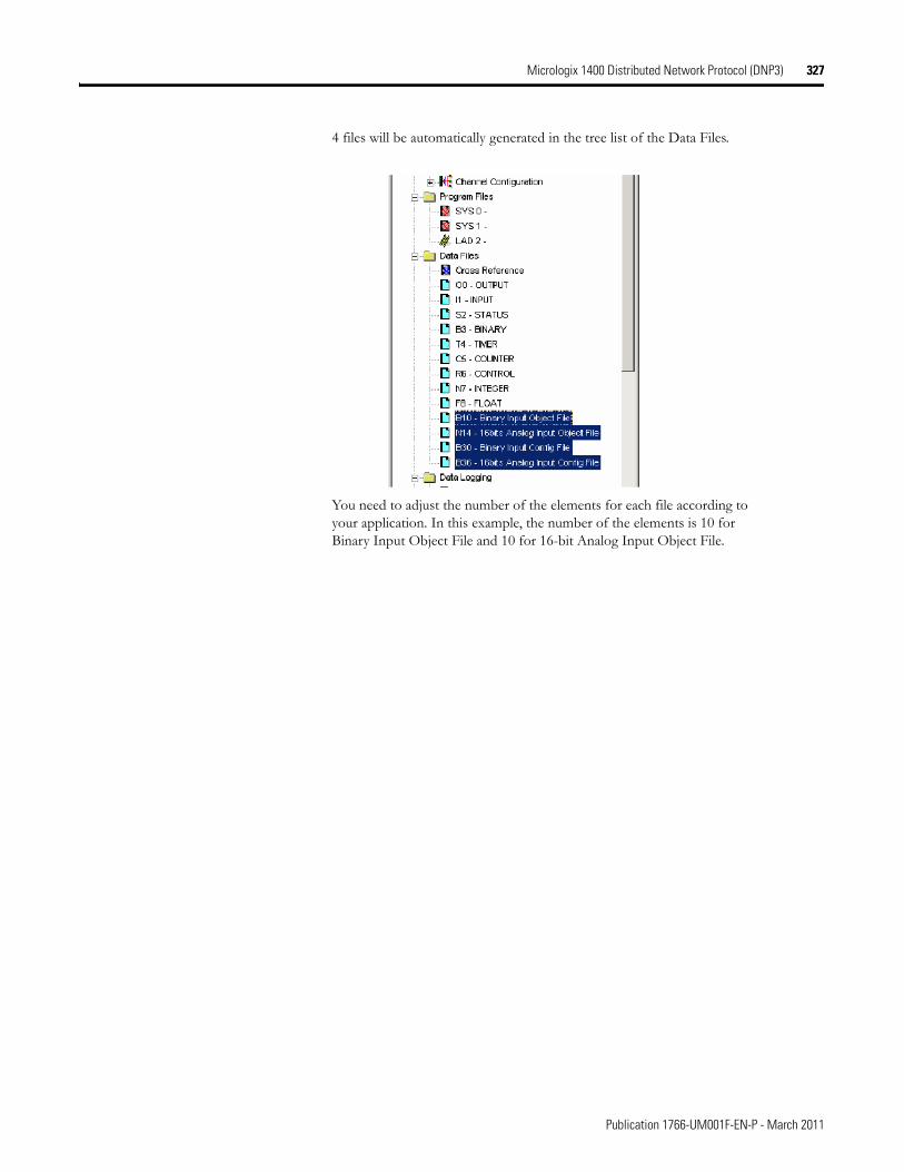
Micrologix 1400 Distributed Network Protocol (DNP3) 327
4 files will be automatically generated in the tree list of the Data Files.
You need to adjust the number of the elements for each file according to your application. In this example, the number of the elements is 10 for Binary Input Object File and 10 for 16-bit Analog Input Object File.
Publication 1766-UM001F-EN-P - March 2011
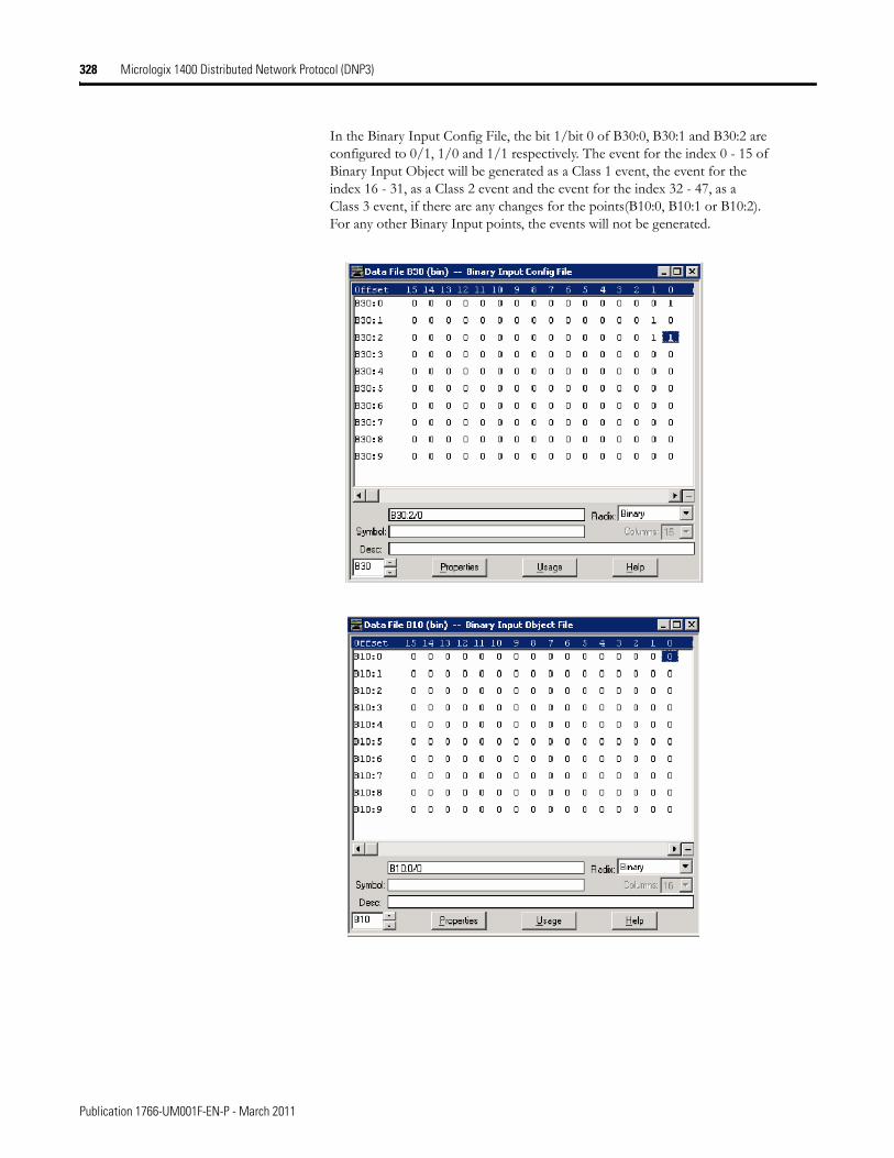
328 Micrologix 1400 Distributed Network Protocol (DNP3)
In the Binary Input Config File, the bit 1/bit 0 of B30:0, B30:1 and B30:2 are configured to 0/1, 1/0 and 1/1 respectively. The event for the index 0 - 15 of Binary Input Object will be generated as a Class 1 event, the event for the index 16 - 31, as a Class 2 event and the event for the index 32 - 47, as a Class 3 event, if there are any changes for the points(B10:0, B10:1 or B10:2). For any other Binary Input points, the events will not be generated.
Publication 1766-UM001F-EN-P - March 2011
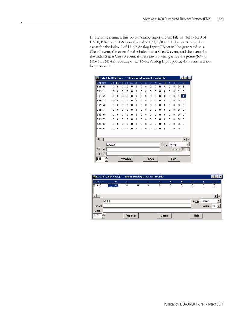
Micrologix 1400 Distributed Network Protocol (DNP3) 329
In the same manner, this 16-bit Analog Input Object File has bit 1/bit 0 of B36:0, B36:1 and B36:2 configured to 0/1, 1/0 and 1/1 respectively. The event for the index 0 of 16-bit Analog Input Object will be generated as a Class 1 event, the event for the index 1 as a Class 2 event, and the event for the index 2 as a Class 3 event, if there are any changes for the points(N14:0, N14:1 or N14:2). For any other 16-bit Analog Input points, the events will not be generated.
Publication 1766-UM001F-EN-P - March 2011
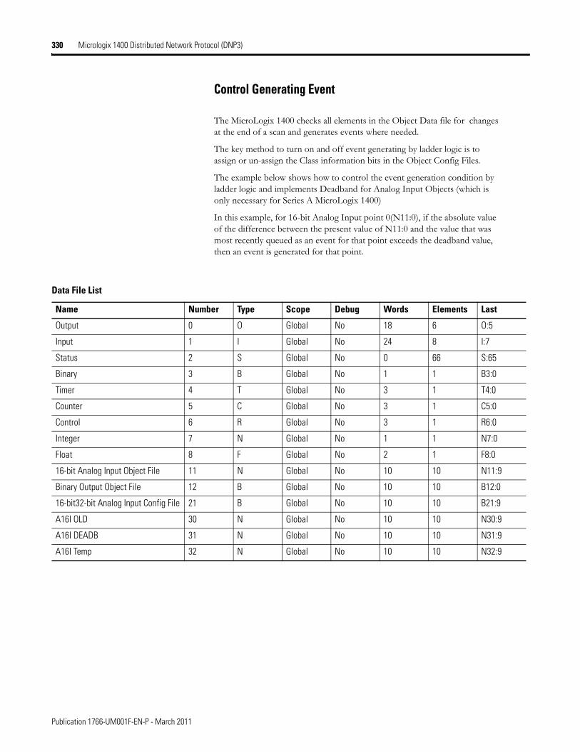
330 Micrologix 1400 Distributed Network Protocol (DNP3)
Control Generating Event
The MicroLogix 1400 checks all elements in the Object Data file for changes at the end of a scan and generates events where needed.
The key method to turn on and off event generating by ladder logic is to assign or un-assign the Class information bits in the Object Config Files.
The example below shows how to control the event generation condition by ladder logic and implements Deadband for Analog Input Objects (which is only necessary for Series A MicroLogix 1400)
In this example, for 16-bit Analog Input point 0(N11:0), if the absolute value of the difference between the present value of N11:0 and the value that was most recently queued as an event for that point exceeds the deadband value, then an event is generated for that point.
Data File List
Name Number Type Scope Debug Words Elements Last
Output 0 O Global No 18 6 O:5
Input 1 I Global No 24 8 I:7
Status 2 S Global No 0 66 S:65
Binary 3 B Global No 1 1 B3:0
Timer 4 T Global No 3 1 T4:0
Counter 5 C Global No 3 1 C5:0
Control 6 R Global No 3 1 R6:0
Integer 7 N Global No 1 1 N7:0
Float 8 F Global No 2 1 F8:0
16-bit Analog Input Object File 11 N Global No 10 10 N11:9
Binary Output Object File 12 B Global No 10 10 B12:0
16-bit32-bit Analog Input Config File 21 B Global No 10 10 B21:9
A16I OLD 30 N Global No 10 10 N30:9
A16I DEADB 31 N Global No 10 10 N31:9
A16I Temp 32 N Global No 10 10 N32:9
Publication 1766-UM001F-EN-P - March 2011
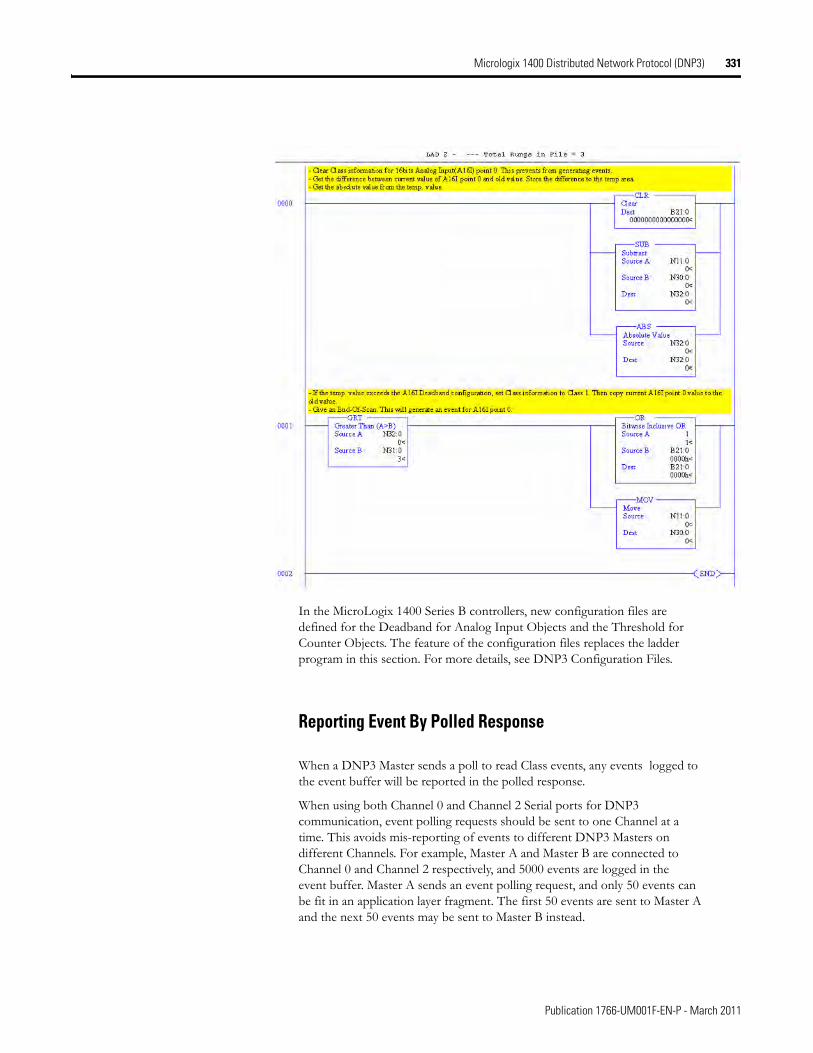
Micrologix 1400 Distributed Network Protocol (DNP3) 331
In the MicroLogix 1400 Series B controllers, new configuration files are defined for the Deadband for Analog Input Objects and the Threshold for Counter Objects. The feature of the configuration files replaces the ladder program in this section. For more details, see DNP3 Configuration Files.
Reporting Event By Polled Response
When a DNP3 Master sends a poll to read Class events, any events logged to the event buffer will be reported in the polled response.
When using both Channel 0 and Channel 2 Serial ports for DNP3 communication, event polling requests should be sent to one Channel at a time. This avoids mis-reporting of events to different DNP3 Masters on different Channels. For example, Master A and Master B are connected to Channel 0 and Channel 2 respectively, and 5000 events are logged in the event buffer. Master A sends an event polling request, and only 50 events can be fit in an application layer fragment. The first 50 events are sent to Master A and the next 50 events may be sent to Master B instead.
Publication 1766-UM001F-EN-P - March 2011

332 Micrologix 1400 Distributed Network Protocol (DNP3)
Reporting Event By Unsolicited Response
To initiate and send Unsolicited Responses to a DNP3 Master, the parameters below should be configured correctly. For more details, see DNP3 Slave Application Layer Configuration Parameters on page 260.
• Master Node0
• Channel for Unsolicited Response
• Enable Unsolicited On Start Up
• Enable Unsolicited For Class1
• Enable Unsolicited For Class2
• Enable Unsolicited For Class3
• Send Initial Unsolicited On Start Up
• Number of Class1 Events
• Hold Time after Class1 Events (x1s)
• Number of Class2 Events
• Hold Time after Class2 Events (x1s)
• Number of Class3 Events
• Hold Time after Class3 Events (x1s)
• DNP3 Object Data File Number
• DNP3 Object Config File Number
• content of the Config File
In some cases, MicroLogix 1400 may not send an Unsolicited Response even though the parameters are configured properly.
• Normally, when the parameter Enable Unsolicited On Start Up is checked, the MicroLogix 1400 initiates an Unsolicited Response with the function code ENABLE_UNSOLICITED(20), if there are any events logged into the event buffer. However, when a request with the function code DISABLE_UNSOLICITED(21) is received, an Unsolicited Response will not be sent.
• When the parameter Enable Unsolicited On Start Up is unchecked, the MicroLogix 1400 does not trigger the Unsolicited Response until a request with the function code ENABLE_UNSOLICITED(20) from the DNP3 Master is received.
Publication 1766-UM001F-EN-P - March 2011
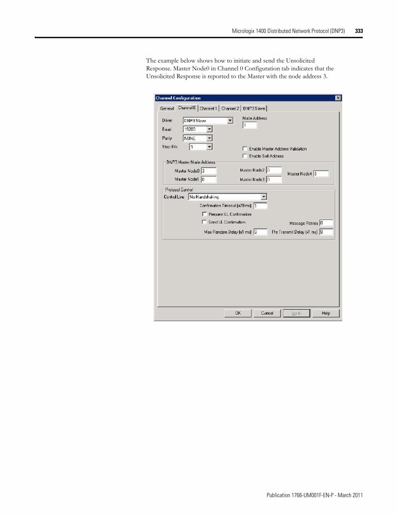
Micrologix 1400 Distributed Network Protocol (DNP3) 333
The example below shows how to initiate and send the Unsolicited Response. Master Node0 in Channel 0 Configuration tab indicates that the Unsolicited Response is reported to the Master with the node address 3.
Publication 1766-UM001F-EN-P - March 2011
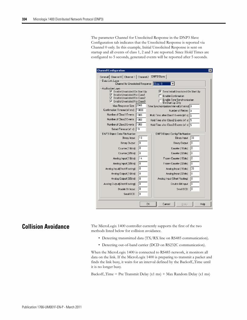
334 Micrologix 1400 Distributed Network Protocol (DNP3)
The parameter Channel for Unsolicited Response in the DNP3 Slave Configuration tab indicates that the Unsolicited Response is reported via Channel 0 only. In this example, Initial Unsolicited Response is sent on startup and all events of class 1, 2 and 3 are reported. Since Hold Times are configured to 5 seconds, generated events will be reported after 5 seconds.
Collision Avoidance The MicroLogix 1400 controller currently supports the first of the two methods listed below for collision avoidance.
• Detecting transmitted data (TX/RX line on RS485 communication).
• Detecting out-of-band carrier (DCD on RS232C communication).
When the MicroLogix 1400 is connected to RS485 network, it monitors all data on the link. If the MicroLogix 1400 is preparing to transmit a packet and finds the link busy, it waits for an interval defined by the Backoff_Time until it is no longer busy.
Backoff_Time = Pre Transmit Delay (x1 ms) + Max Random Delay (x1 ms)
Publication 1766-UM001F-EN-P - March 2011
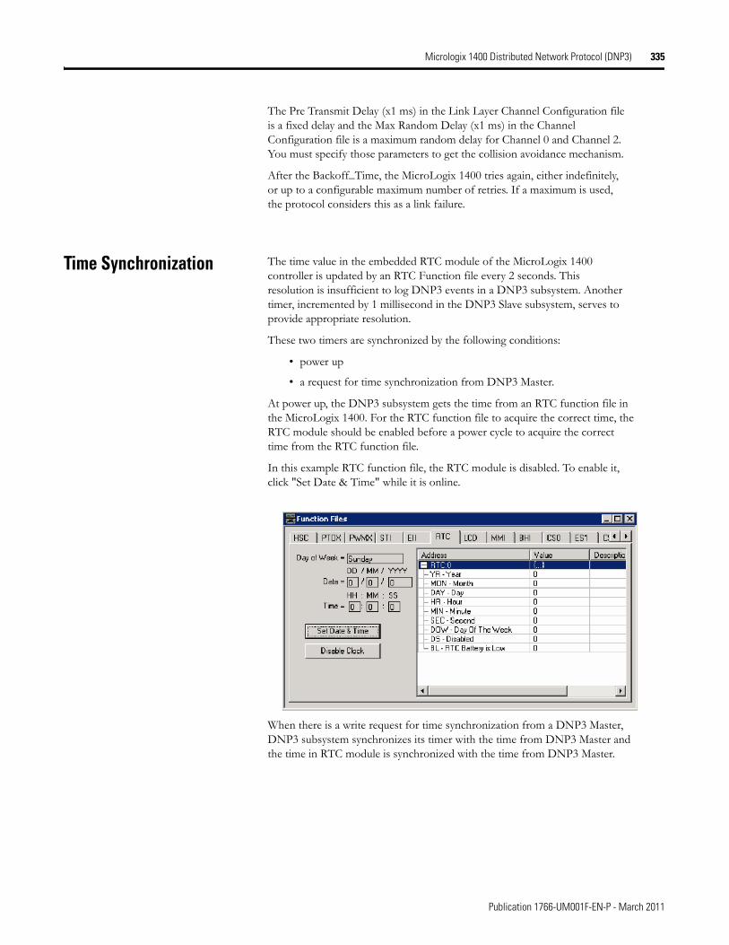
Micrologix 1400 Distributed Network Protocol (DNP3) 335
The Pre Transmit Delay (x1 ms) in the Link Layer Channel Configuration file is a fixed delay and the Max Random Delay (x1 ms) in the Channel Configuration file is a maximum random delay for Channel 0 and Channel 2. You must specify those parameters to get the collision avoidance mechanism.
After the Backoff_Time, the MicroLogix 1400 tries again, either indefinitely, or up to a configurable maximum number of retries. If a maximum is used, the protocol considers this as a link failure.
Time Synchronization The time value in the embedded RTC module of the MicroLogix 1400 controller is updated by an RTC Function file every 2 seconds. This resolution is insufficient to log DNP3 events in a DNP3 subsystem. Another timer, incremented by 1 millisecond in the DNP3 Slave subsystem, serves to provide appropriate resolution.
These two timers are synchronized by the following conditions:
• power up
• a request for time synchronization from DNP3 Master.
At power up, the DNP3 subsystem gets the time from an RTC function file in the MicroLogix 1400. For the RTC function file to acquire the correct time, the RTC module should be enabled before a power cycle to acquire the correct time from the RTC function file.
In this example RTC function file, the RTC module is disabled. To enable it, click "Set Date & Time" while it is online.
When there is a write request for time synchronization from a DNP3 Master, DNP3 subsystem synchronizes its timer with the time from DNP3 Master and the time in RTC module is synchronized with the time from DNP3 Master.
Publication 1766-UM001F-EN-P - March 2011
336 Micrologix 1400 Distributed Network Protocol (DNP3)
This table shows RTC Accuracy. Configure the NEED_TIME IIN bit according to this table, so that a DNP3 Master can send the time synchronization request for more accurate times in the controller.
Download a User Program via DNP3 Network
Using File-Control/Status of Requested Operation objects, a user program can be downloaded/uploaded/initialized via DNP3 communication. Also, Serial Channel 0 Status File, Ethernet Channel 1 Status File, and Serial Channel 2 Status File can be uploaded from the MicroLogix 1400.
All File-Control/Status of Requested Operation objects and supported File-Control/Status of Requested Operation objects are listed in this section. Unsolicited Response for File-Control/Status of Requested Operation objects is not supported. All the responses are sent to DNP3 Master with Function Code 129(81h).
• g70v1 File-Control - File identifier : superseded, not supported
• g70v2 File-Control - Authentication : supported
• g70v3 File-Control - File command : supported
• g70v4 File-Control - File command status : supported
• g70v5 File-Control - File transport : supported
• g70v6 File-Control - File transport status : supported
• g70v7 File-Control - File descriptor : supported
• g70v8 File-Control - File specification string : not supported by Series A controllers, supported by Series B controllers
• g91v1 Status of Requested Operation - Activate configuration : not supported by Series A controllers, supported by Series B controllers
RTC Accuracy
Ambient Temperature RTC Accuracy(1)
(1) These numbers are maximum worst case values over a 31-day month.
0 °C (32 °F) -13...-121 seconds/month
25 °C (77 °F) 54...-5 seconds/month
40 °C (104 °F) 29...-78 seconds/month
55 °C (131 °F) -43...-150 seconds/month
Publication 1766-UM001F-EN-P - March 2011
Micrologix 1400 Distributed Network Protocol (DNP3) 337
Default Directories and Files
The MicroLogix 1400 has default directories and files for file handling in a DNP3 subsystem.
The default directories and files can be read from the controller using the function code OPEN_FILE(25), Read(1), and CLOSE_FILE(26).
Currently supported directories are "/EXE" and "/DIAG". Supported files are listed in this section. These directories/files cannot be removed and cannot be created using DNP3 requests.
• The directory/file names must all be in capital letters.
• Root level can only be a directory marker. The directory marker is "/" for Series A, or "\" for Series B.
• Directory level can only contain directories.
• File level can only contain files.
Note that the directory marker is different in the MicroLogix 1400 Series A and Series B controllers. The directory marker is "/" for Series A and "\" for Series B controllers. In this document, "/" is used to explain File Object feature.
Generating *.IMG files using RSLogix 500/RSLogix Micro
Typically, RSLogix 500/RSLogix Micro stores the ladder program as "RSLogix Files (*.RSS)". However, to download a ladder program using a File Object via DNP3 network, you must save your ladder program in the "RSLogix IMG Files (*.IMG)" format.
Supported Files and Directories
Root Level
Directory Level
File Level Full name string to access
"/" "/"
"EXE" "/EXE"
"[processorName].IMG" "/EXE/[processorName].IMG"
"DIAG" "/DIAG"
"CH0.CSF" "/DIAG/CH0.CSF"
"CH1.ESF" "/DIAG/CH1.ESF"
"CH2.CSF" "/DIAG/CH2.CSF"
Publication 1766-UM001F-EN-P - March 2011
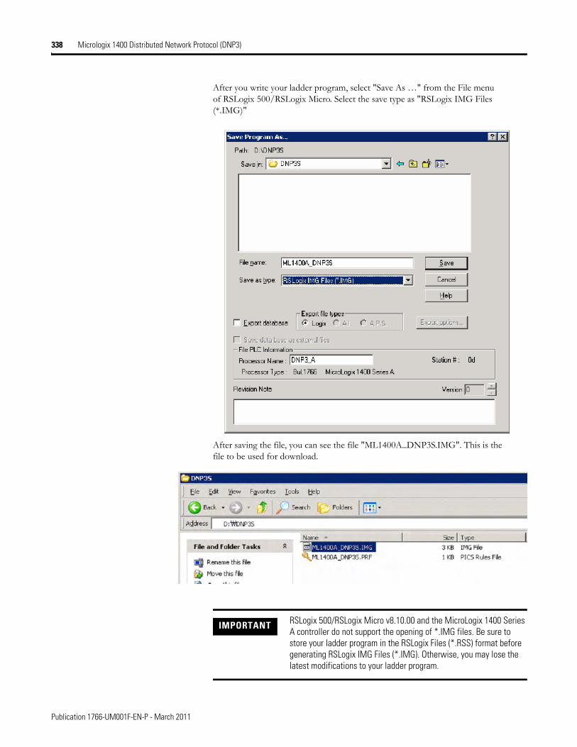
338 Micrologix 1400 Distributed Network Protocol (DNP3)
After you write your ladder program, select "Save As …" from the File menu of RSLogix 500/RSLogix Micro. Select the save type as "RSLogix IMG Files (*.IMG)"
After saving the file, you can see the file "ML1400A_DNP3S.IMG". This is the file to be used for download.
IMPORTANT RSLogix 500/RSLogix Micro v8.10.00 and the MicroLogix 1400 Series A controller do not support the opening of *.IMG files. Be sure to store your ladder program in the RSLogix Files (*.RSS) format before generating RSLogix IMG Files (*.IMG). Otherwise, you may lose the latest modifications to your ladder program.
Publication 1766-UM001F-EN-P - March 2011
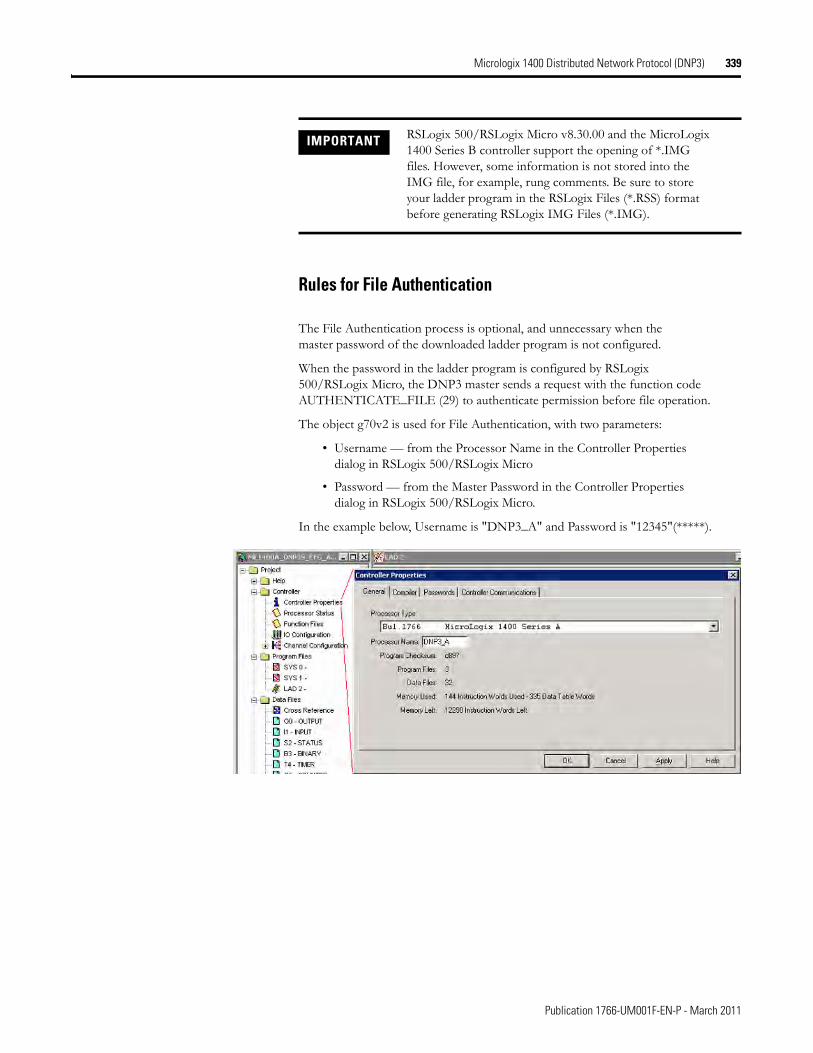
Micrologix 1400 Distributed Network Protocol (DNP3) 339
Rules for File Authentication
The File Authentication process is optional, and unnecessary when the master password of the downloaded ladder program is not configured.
When the password in the ladder program is configured by RSLogix 500/RSLogix Micro, the DNP3 master sends a request with the function code AUTHENTICATE_FILE (29) to authenticate permission before file operation.
The object g70v2 is used for File Authentication, with two parameters:
• Username — from the Processor Name in the Controller Properties dialog in RSLogix 500/RSLogix Micro
• Password — from the Master Password in the Controller Properties dialog in RSLogix 500/RSLogix Micro.
In the example below, Username is "DNP3_A" and Password is "12345"(*****).
IMPORTANT RSLogix 500/RSLogix Micro v8.30.00 and the MicroLogix 1400 Series B controller support the opening of *.IMG files. However, some information is not stored into the IMG file, for example, rung comments. Be sure to store your ladder program in the RSLogix Files (*.RSS) format before generating RSLogix IMG Files (*.IMG).
Publication 1766-UM001F-EN-P - March 2011
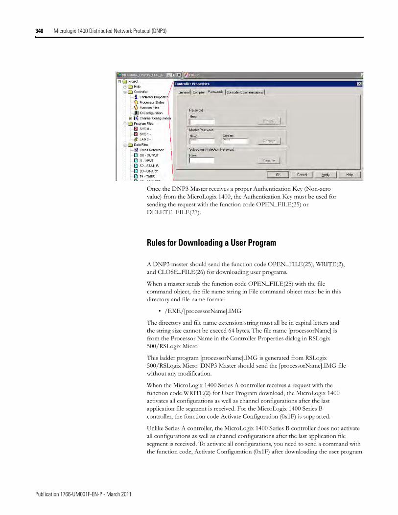
340 Micrologix 1400 Distributed Network Protocol (DNP3)
Once the DNP3 Master receives a proper Authentication Key (Non-zero value) from the MicroLogix 1400, the Authentication Key must be used for sending the request with the function code OPEN_FILE(25) or DELETE_FILE(27).
Rules for Downloading a User Program
A DNP3 master should send the function code OPEN_FILE(25), WRITE(2), and CLOSE_FILE(26) for downloading user programs.
When a master sends the function code OPEN_FILE(25) with the file command object, the file name string in File command object must be in this directory and file name format:
• /EXE/[processorName].IMG
The directory and file name extension string must all be in capital letters and the string size cannot be exceed 64 bytes. The file name [processorName] is from the Processor Name in the Controller Properties dialog in RSLogix 500/RSLogix Micro.
This ladder program [processorName].IMG is generated from RSLogix 500/RSLogix Micro. DNP3 Master should send the [processorName].IMG file without any modification.
When the MicroLogix 1400 Series A controller receives a request with the function code WRITE(2) for User Program download, the MicroLogix 1400 activates all configurations as well as channel configurations after the last application file segment is received. For the MicroLogix 1400 Series B controller, the function code Activate Configuration (0x1F) is supported.
Unlike Series A controller, the MicroLogix 1400 Series B controller does not activate all configurations as well as channel configurations after the last application file segment is received. To activate all configurations, you need to send a command with the function code, Activate Configuration (0x1F) after downloading the user program.
Publication 1766-UM001F-EN-P - March 2011

Micrologix 1400 Distributed Network Protocol (DNP3) 341
Maximum file size is 384 Kbytes. The MicroLogix 1400 supports downloading up to 256Kbyte size of user program when Recipe is not configured. When Recipe is configured, Maximum file size is 384 Kbytes.
The first application segment of the ladder program should be larger than or equal to the size of System Exe File structure, 64 bytes.
An application segment of the ladder program cannot be exceed 2048 bytes.
When the MicroLogix 1400 receives the first application segment, it acquires Edit Resource from the system. If the last application segment is received properly, the MicroLogix 1400 returns Edit Resource to the system. After acquiring Edit Resource, each of the application segments should be received within the Edit Resource/Owner Timeout.
The MicroLogix 1400 controller checks the integrity of the program after receiving the last application segment. If the downloaded user program fails the integrity check, MicroLogix 1400 clears the downloaded user program and restores the default user program. In this case, the configured Channel configuration is not changed from the last valid configuration.
A user program cannot be downloaded while the controller is in Executing mode. Before downloading, send a mode change request with the function code STOP_APPL(18). See Starting and Stopping User Programs (Mode Change) via DNP3 Network on page 342 for more details.
Executing modes include Run, Remote Run, Test Continuous Scan, and Test Single Scan modes. Any others are Non-Executing modes.
Rules for Uploading a User Program
A DNP3 master should send the function code OPEN_FILE(25), READ(1), and CLOSE_FILE(26) for uploading user programs.
When a master sends the function code OPEN_FILE(25) with the file command object, the file name string in File command object must be in this directory and file name format:
• /EXE/[processorName].IMG
The directory and file name extension string must all be in capital letters and the string size cannot be exceed 64 bytes. The file name [processorName] is from the Processor Name in the Controller Properties dialog in RSLogix 500/RSLogix Micro.
The maximum file size is 384 Kbytes. The MicroLogix 1400 supports uploading of user programs up to 256Kbyte in size when Recipe is not configured. When Recipe is configured, Maximum file size is 384 Kbytes.
The first application segment of the ladder program should be larger than or equal to the size of System Exe File structure, 64 bytes.
An application segment of the ladder program cannot be exceed 2048 bytes.
Publication 1766-UM001F-EN-P - March 2011
342 Micrologix 1400 Distributed Network Protocol (DNP3)
Rules for Initializing a User Program
A DNP3 master should send the function code DELETE_FILE(27) for initializing user programs.
When MicroLogix 1400 receives a request with the function code DELETE_FILE(27), it clears the current user program which was downloaded into the controller, and restores the default user program.
User programs cannot be initialized while the controller is in Executing mode. Before initializing programs, a mode change request should be sent with the function code STOP_APPL(18).
Rules for uploading Communication Status Files
A DNP3 master should send the function code OPEN_FILE(25), READ(1), and CLOSE_FILE(26) for uploading Communication Status Files.
The function code WRITE(2) for downloading Communication Status Files is not supported.
The file name should be "/DIAG/CH0.CSF", "/DIAG/CH1.ESF", and "/DIAG/CH2.CSF" for Channel 0, Channel 1, and Channel 2 respectively.
Starting and Stopping User Programs (Mode Change) via DNP3 Network
This section covers how to change the controller mode via DNP3 network.
To change the controller mode, use the function codes FC_INITIALIZE_APPL (16), FC_START_APPL (17) and FC_STOP_APPL (18).
Publication 1766-UM001F-EN-P - March 2011
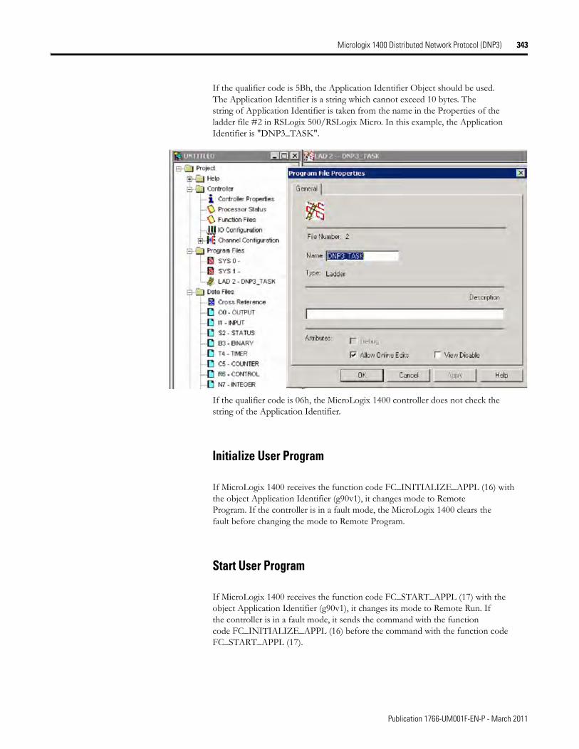
Micrologix 1400 Distributed Network Protocol (DNP3) 343
If the qualifier code is 5Bh, the Application Identifier Object should be used. The Application Identifier is a string which cannot exceed 10 bytes. The string of Application Identifier is taken from the name in the Properties of the ladder file #2 in RSLogix 500/RSLogix Micro. In this example, the Application Identifier is "DNP3_TASK".
If the qualifier code is 06h, the MicroLogix 1400 controller does not check the string of the Application Identifier.
Initialize User Program
If MicroLogix 1400 receives the function code FC_INITIALIZE_APPL (16) with the object Application Identifier (g90v1), it changes mode to Remote Program. If the controller is in a fault mode, the MicroLogix 1400 clears the fault before changing the mode to Remote Program.
Start User Program
If MicroLogix 1400 receives the function code FC_START_APPL (17) with the object Application Identifier (g90v1), it changes its mode to Remote Run. If the controller is in a fault mode, it sends the command with the function code FC_INITIALIZE_APPL (16) before the command with the function code FC_START_APPL (17).
Publication 1766-UM001F-EN-P - March 2011
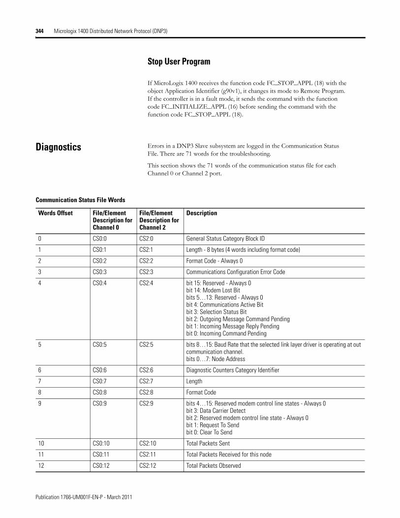
344 Micrologix 1400 Distributed Network Protocol (DNP3)
Stop User Program
If MicroLogix 1400 receives the function code FC_STOP_APPL (18) with the object Application Identifier (g90v1), it changes its mode to Remote Program. If the controller is in a fault mode, it sends the command with the function code FC_INITIALIZE_APPL (16) before sending the command with the function code FC_STOP_APPL (18).
Diagnostics Errors in a DNP3 Slave subsystem are logged in the Communication Status File. There are 71 words for the troubleshooting.
This section shows the 71 words of the communication status file for each Channel 0 or Channel 2 port.
Communication Status File Words
Words Offset File/Element Description for Channel 0
File/Element Description for Channel 2
Description
0 CS0:0 CS2:0 General Status Category Block ID
1 CS0:1 CS2:1 Length - 8 bytes (4 words including format code)
2 CS0:2 CS2:2 Format Code - Always 0
3 CS0:3 CS2:3 Communications Configuration Error Code
4 CS0:4 CS2:4 bit 15: Reserved - Always 0bit 14: Modem Lost Bitbits 5…13: Reserved - Always 0bit 4: Communications Active Bitbit 3: Selection Status Bitbit 2: Outgoing Message Command Pending bit 1: Incoming Message Reply Pendingbit 0: Incoming Command Pending
5 CS0:5 CS2:5 bits 8…15: Baud Rate that the selected link layer driver is operating at out communication channel.bits 0…7: Node Address
6 CS0:6 CS2:6 Diagnostic Counters Category Identifier
7 CS0:7 CS2:7 Length
8 CS0:8 CS2:8 Format Code
9 CS0:9 CS2:9 bits 4…15: Reserved modem control line states - Always 0 bit 3: Data Carrier Detectbit 2: Reserved modem control line state - Always 0bit 1: Request To Sendbit 0: Clear To Send
10 CS0:10 CS2:10 Total Packets Sent
11 CS0:11 CS2:11 Total Packets Received for this node
12 CS0:12 CS2:12 Total Packets Observed
Publication 1766-UM001F-EN-P - March 2011

Micrologix 1400 Distributed Network Protocol (DNP3) 345
13 CS0:13 CS2:13 Undelivered Message Packets
14 CS0:14 CS2:14 Message Packets Retried
15 CS0:15 CS2:15 NAK Packets Received
16 CS0:16 CS2:16 Link Layer Error Count
17 CS0:17 CS2:17 Link Layer Error Codes0: ERR_NO_ERROR1: ERR_NO_RX_BUFFER2: ERR_TOO_SHORT3: ERR_TOO_LONG4: ERR_UART_ERROR5: ERR_BAD_CRC6: ERR_CTS_TIMEOUT7: ERR_CTS_DROP_MID_PKT8: ERR_UNKNOWN_CHAR
18 CS0:18 CS2:18 Reserved - Always 0
19 CS0:19 CS2:19 Reserved - Always 0
20 CS0:20 CS2:20 Reserved - Always 0
21 CS0:21 CS2:21 Reserved - Always 0
22 CS0:22 CS2:22 Reserved - Always 0
23 CS0:23 CS2:23 Data Link Layer Active Node Table
24 CS0:24 CS2:24 Length
25 CS0:25 CS2:25 Format Code
26 CS0:26 CS2:26 Number of Nodes
27 CS0:27 CS2:27 Reserved - Always 0
28 CS0:28 CS2:28 Reserved - Always 0
29 CS0:29 CS2:29 Reserved - Always 0
30 CS0:30 CS2:30 Reserved - Always 0
31 CS0:31 CS2:31 Reserved - Always 0
32 CS0:32 CS2:32 Reserved - Always 0
33 CS0:33 CS2:33 Reserved - Always 0
34 CS0:34 CS2:34 Reserved - Always 0
35 CS0:35 CS2:35 Reserved - Always 0
36 CS0:36 CS2:36 Reserved - Always 0
37 CS0:37 CS2:37 Reserved - Always 0
38 CS0:38 CS2:38 Reserved - Always 0
39 CS0:39 CS2:39 Reserved - Always 0
40 CS0:40 CS2:40 Reserved - Always 0
41 CS0:41 CS2:41 Reserved - Always 0
Communication Status File Words
Words Offset File/Element Description for Channel 0
File/Element Description for Channel 2
Description
Publication 1766-UM001F-EN-P - March 2011
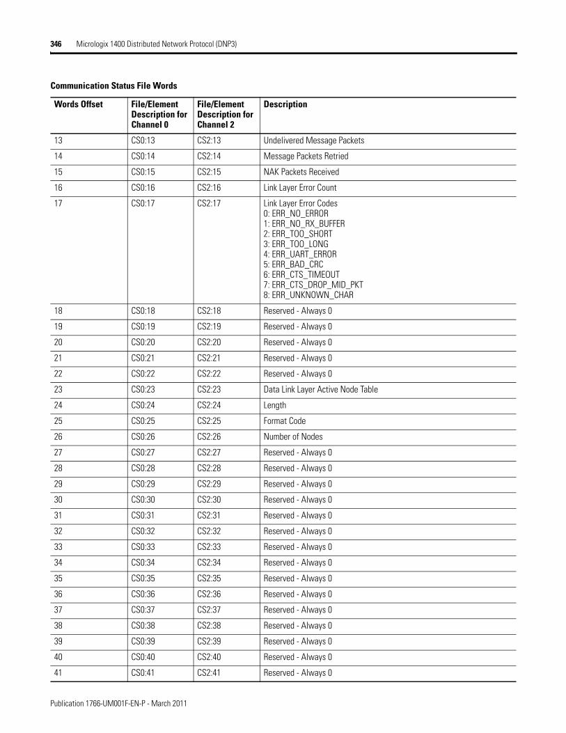
346 Micrologix 1400 Distributed Network Protocol (DNP3)
13 CS0:13 CS2:13 Undelivered Message Packets
14 CS0:14 CS2:14 Message Packets Retried
15 CS0:15 CS2:15 NAK Packets Received
16 CS0:16 CS2:16 Link Layer Error Count
17 CS0:17 CS2:17 Link Layer Error Codes0: ERR_NO_ERROR1: ERR_NO_RX_BUFFER2: ERR_TOO_SHORT3: ERR_TOO_LONG4: ERR_UART_ERROR5: ERR_BAD_CRC6: ERR_CTS_TIMEOUT7: ERR_CTS_DROP_MID_PKT8: ERR_UNKNOWN_CHAR
18 CS0:18 CS2:18 Reserved - Always 0
19 CS0:19 CS2:19 Reserved - Always 0
20 CS0:20 CS2:20 Reserved - Always 0
21 CS0:21 CS2:21 Reserved - Always 0
22 CS0:22 CS2:22 Reserved - Always 0
23 CS0:23 CS2:23 Data Link Layer Active Node Table
24 CS0:24 CS2:24 Length
25 CS0:25 CS2:25 Format Code
26 CS0:26 CS2:26 Number of Nodes
27 CS0:27 CS2:27 Reserved - Always 0
28 CS0:28 CS2:28 Reserved - Always 0
29 CS0:29 CS2:29 Reserved - Always 0
30 CS0:30 CS2:30 Reserved - Always 0
31 CS0:31 CS2:31 Reserved - Always 0
32 CS0:32 CS2:32 Reserved - Always 0
33 CS0:33 CS2:33 Reserved - Always 0
34 CS0:34 CS2:34 Reserved - Always 0
35 CS0:35 CS2:35 Reserved - Always 0
36 CS0:36 CS2:36 Reserved - Always 0
37 CS0:37 CS2:37 Reserved - Always 0
38 CS0:38 CS2:38 Reserved - Always 0
39 CS0:39 CS2:39 Reserved - Always 0
40 CS0:40 CS2:40 Reserved - Always 0
41 CS0:41 CS2:41 Reserved - Always 0
Communication Status File Words
Words Offset File/Element Description for Channel 0
File/Element Description for Channel 2
Description
Publication 1766-UM001F-EN-P - March 2011
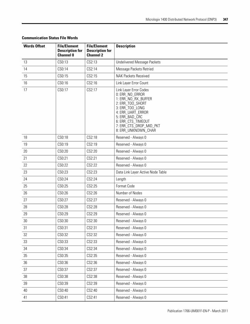
Micrologix 1400 Distributed Network Protocol (DNP3) 347
13 CS0:13 CS2:13 Undelivered Message Packets
14 CS0:14 CS2:14 Message Packets Retried
15 CS0:15 CS2:15 NAK Packets Received
16 CS0:16 CS2:16 Link Layer Error Count
17 CS0:17 CS2:17 Link Layer Error Codes0: ERR_NO_ERROR1: ERR_NO_RX_BUFFER2: ERR_TOO_SHORT3: ERR_TOO_LONG4: ERR_UART_ERROR5: ERR_BAD_CRC6: ERR_CTS_TIMEOUT7: ERR_CTS_DROP_MID_PKT8: ERR_UNKNOWN_CHAR
18 CS0:18 CS2:18 Reserved - Always 0
19 CS0:19 CS2:19 Reserved - Always 0
20 CS0:20 CS2:20 Reserved - Always 0
21 CS0:21 CS2:21 Reserved - Always 0
22 CS0:22 CS2:22 Reserved - Always 0
23 CS0:23 CS2:23 Data Link Layer Active Node Table
24 CS0:24 CS2:24 Length
25 CS0:25 CS2:25 Format Code
26 CS0:26 CS2:26 Number of Nodes
27 CS0:27 CS2:27 Reserved - Always 0
28 CS0:28 CS2:28 Reserved - Always 0
29 CS0:29 CS2:29 Reserved - Always 0
30 CS0:30 CS2:30 Reserved - Always 0
31 CS0:31 CS2:31 Reserved - Always 0
32 CS0:32 CS2:32 Reserved - Always 0
33 CS0:33 CS2:33 Reserved - Always 0
34 CS0:34 CS2:34 Reserved - Always 0
35 CS0:35 CS2:35 Reserved - Always 0
36 CS0:36 CS2:36 Reserved - Always 0
37 CS0:37 CS2:37 Reserved - Always 0
38 CS0:38 CS2:38 Reserved - Always 0
39 CS0:39 CS2:39 Reserved - Always 0
40 CS0:40 CS2:40 Reserved - Always 0
41 CS0:41 CS2:41 Reserved - Always 0
Communication Status File Words
Words Offset File/Element Description for Channel 0
File/Element Description for Channel 2
Description
Publication 1766-UM001F-EN-P - March 2011
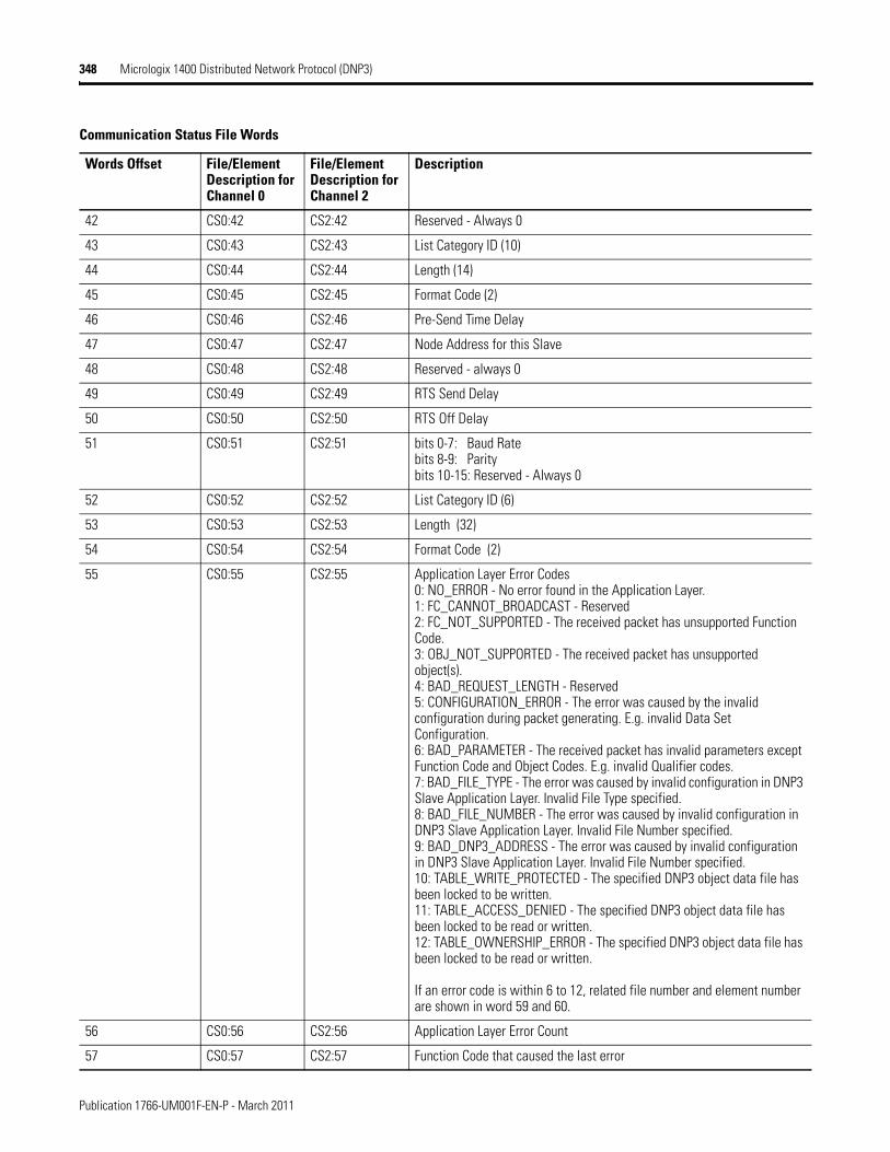
348 Micrologix 1400 Distributed Network Protocol (DNP3)
42 CS0:42 CS2:42 Reserved - Always 0
43 CS0:43 CS2:43 List Category ID (10)
44 CS0:44 CS2:44 Length (14)
45 CS0:45 CS2:45 Format Code (2)
46 CS0:46 CS2:46 Pre-Send Time Delay
47 CS0:47 CS2:47 Node Address for this Slave
48 CS0:48 CS2:48 Reserved - always 0
49 CS0:49 CS2:49 RTS Send Delay
50 CS0:50 CS2:50 RTS Off Delay
51 CS0:51 CS2:51 bits 0-7: Baud Ratebits 8-9: Parity bits 10-15: Reserved - Always 0
52 CS0:52 CS2:52 List Category ID (6)
53 CS0:53 CS2:53 Length (32)
54 CS0:54 CS2:54 Format Code (2)
55 CS0:55 CS2:55 Application Layer Error Codes0: NO_ERROR - No error found in the Application Layer.1: FC_CANNOT_BROADCAST - Reserved2: FC_NOT_SUPPORTED - The received packet has unsupported Function Code.3: OBJ_NOT_SUPPORTED - The received packet has unsupported object(s).4: BAD_REQUEST_LENGTH - Reserved5: CONFIGURATION_ERROR - The error was caused by the invalid configuration during packet generating. E.g. invalid Data Set Configuration.6: BAD_PARAMETER - The received packet has invalid parameters except Function Code and Object Codes. E.g. invalid Qualifier codes.7: BAD_FILE_TYPE - The error was caused by invalid configuration in DNP3 Slave Application Layer. Invalid File Type specified.8: BAD_FILE_NUMBER - The error was caused by invalid configuration in DNP3 Slave Application Layer. Invalid File Number specified.9: BAD_DNP3_ADDRESS - The error was caused by invalid configuration in DNP3 Slave Application Layer. Invalid File Number specified.10: TABLE_WRITE_PROTECTED - The specified DNP3 object data file has been locked to be written.11: TABLE_ACCESS_DENIED - The specified DNP3 object data file has been locked to be read or written.12: TABLE_OWNERSHIP_ERROR - The specified DNP3 object data file has been locked to be read or written.
If an error code is within 6 to 12, related file number and element number are shown in word 59 and 60.
56 CS0:56 CS2:56 Application Layer Error Count
57 CS0:57 CS2:57 Function Code that caused the last error
Communication Status File Words
Words Offset File/Element Description for Channel 0
File/Element Description for Channel 2
Description
Publication 1766-UM001F-EN-P - March 2011
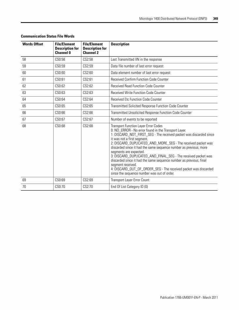
Micrologix 1400 Distributed Network Protocol (DNP3) 349
58 CS0:58 CS2:58 Last Transmitted IIN in the response
59 CS0:59 CS2:59 Data file number of last error request
60 CS0:60 CS2:60 Data element number of last error request
61 CS0:61 CS2:61 Received Confirm Function Code Counter
62 CS0:62 CS2:62 Received Read Function Code Counter
63 CS0:63 CS2:63 Received Write Function Code Counter
64 CS0:64 CS2:64 Received Etc Function Code Counter
65 CS0:65 CS2:65 Transmitted Solicited Response Function Code Counter
66 CS0:66 CS2:66 Transmitted Unsolicited Response Function Code Counter
67 CS0:67 CS2:67 Number of events to be reported
68 CS0:68 CS2:68 Transport Function Layer Error Codes0: NO_ERROR - No error found in the Transport Layer.1: DISCARD_NOT_FIRST_SEG - The received packet was discarded since it was not a first segment.2: DISCARD_DUPLICATED_AND_MORE_SEG - The received packet was discarded since it had the same sequence number as previous, more segments are expected.3: DISCARD_DUPLICATED_AND_FINAL_SEG - The received packet was discarded since it had the same sequence number as previous, final segment received.4: DISCARD_OUT_OF_ORDER_SEG - The received packet was discarded since the sequence number was out of order.
69 CS0:69 CS2:69 Transport Layer Error Count
70 CS0:70 CS2:70 End Of List Category ID (0)
Communication Status File Words
Words Offset File/Element Description for Channel 0
File/Element Description for Channel 2
Description
Publication 1766-UM001F-EN-P - March 2011
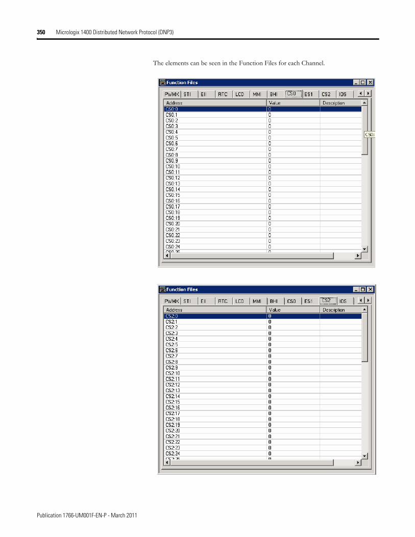
350 Micrologix 1400 Distributed Network Protocol (DNP3)
The elements can be seen in the Function Files for each Channel.
Publication 1766-UM001F-EN-P - March 2011
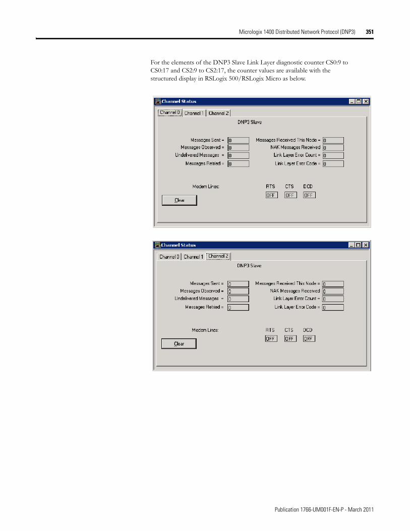
Micrologix 1400 Distributed Network Protocol (DNP3) 351
For the elements of the DNP3 Slave Link Layer diagnostic counter CS0:9 to CS0:17 and CS2:9 to CS2:17, the counter values are available with the structured display in RSLogix 500/RSLogix Micro as below.
Publication 1766-UM001F-EN-P - March 2011
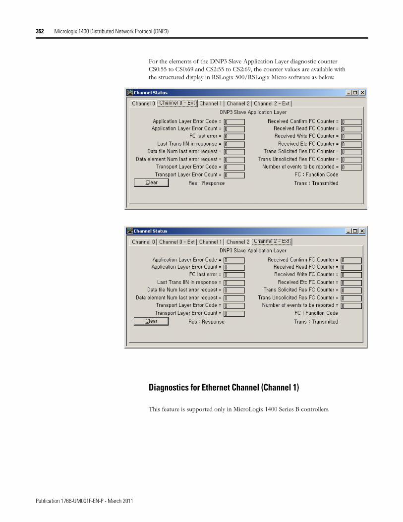
352 Micrologix 1400 Distributed Network Protocol (DNP3)
For the elements of the DNP3 Slave Application Layer diagnostic counter CS0:55 to CS0:69 and CS2:55 to CS2:69, the counter values are available with the structured display in RSLogix 500/RSLogix Micro software as below.
Diagnostics for Ethernet Channel (Channel 1)
This feature is supported only in MicroLogix 1400 Series B controllers.
Publication 1766-UM001F-EN-P - March 2011
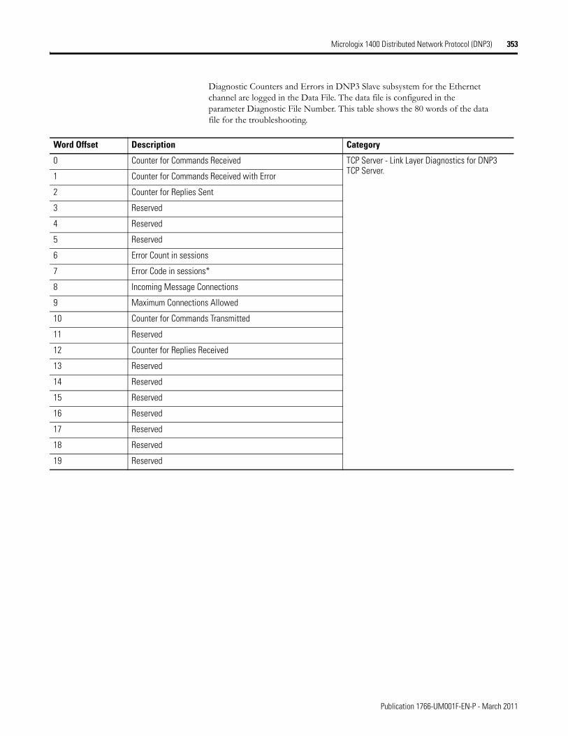
Micrologix 1400 Distributed Network Protocol (DNP3) 353
Diagnostic Counters and Errors in DNP3 Slave subsystem for the Ethernet channel are logged in the Data File. The data file is configured in the parameter Diagnostic File Number. This table shows the 80 words of the data file for the troubleshooting.
Word Offset Description Category
0 Counter for Commands Received TCP Server - Link Layer Diagnostics for DNP3 TCP Server.
1 Counter for Commands Received with Error
2 Counter for Replies Sent
3 Reserved
4 Reserved
5 Reserved
6 Error Count in sessions
7 Error Code in sessions*
8 Incoming Message Connections
9 Maximum Connections Allowed
10 Counter for Commands Transmitted
11 Reserved
12 Counter for Replies Received
13 Reserved
14 Reserved
15 Reserved
16 Reserved
17 Reserved
18 Reserved
19 Reserved
Publication 1766-UM001F-EN-P - March 2011
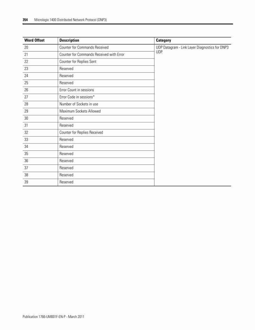
354 Micrologix 1400 Distributed Network Protocol (DNP3)
20 Counter for Commands Received UDP Datagram - Link Layer Diagnostics for DNP3 UDP.
21 Counter for Commands Received with Error
22 Counter for Replies Sent
23 Reserved
24 Reserved
25 Reserved
26 Error Count in sessions
27 Error Code in sessions*
28 Number of Sockets in use
29 Maximum Sockets Allowed
30 Reserved
31 Reserved
32 Counter for Replies Received
33 Reserved
34 Reserved
35 Reserved
36 Reserved
37 Reserved
38 Reserved
39 Reserved
Word Offset Description Category
Publication 1766-UM001F-EN-P - March 2011
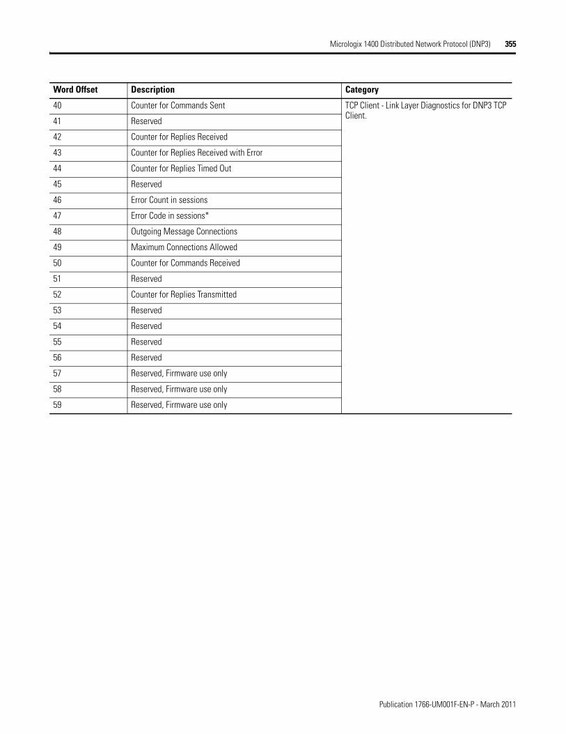
Micrologix 1400 Distributed Network Protocol (DNP3) 355
40 Counter for Commands Sent TCP Client - Link Layer Diagnostics for DNP3 TCP Client.
41 Reserved
42 Counter for Replies Received
43 Counter for Replies Received with Error
44 Counter for Replies Timed Out
45 Reserved
46 Error Count in sessions
47 Error Code in sessions*
48 Outgoing Message Connections
49 Maximum Connections Allowed
50 Counter for Commands Received
51 Reserved
52 Counter for Replies Transmitted
53 Reserved
54 Reserved
55 Reserved
56 Reserved
57 Reserved, Firmware use only
58 Reserved, Firmware use only
59 Reserved, Firmware use only
Word Offset Description Category
Publication 1766-UM001F-EN-P - March 2011
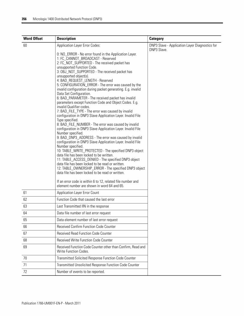
356 Micrologix 1400 Distributed Network Protocol (DNP3)
60 Application Layer Error Codes:
0: NO_ERROR - No error found in the Application Layer.1: FC_CANNOT_BROADCAST - Reserved2: FC_NOT_SUPPORTED - The received packet has unsupported Function Code.3: OBJ_NOT_SUPPORTED - The received packet has unsupported object(s).4: BAD_REQUEST_LENGTH - Reserved5: CONFIGURATION_ERROR - The error was caused by the invalid configuration during packet generating. E.g. invalid Data Set Configuration.6: BAD_PARAMETER - The received packet has invalid parameters except Function Code and Object Codes. E.g. invalid Qualifier codes.7: BAD_FILE_TYPE - The error was caused by invalid configuration in DNP3 Slave Application Layer. Invalid File Type specified.8: BAD_FILE_NUMBER - The error was caused by invalid configuration in DNP3 Slave Application Layer. Invalid File Number specified.9: BAD_DNP3_ADDRESS - The error was caused by invalid configuration in DNP3 Slave Application Layer. Invalid File Number specified.10: TABLE_WRITE_PROTECTED - The specified DNP3 object data file has been locked to be written.11: TABLE_ACCESS_DENIED - The specified DNP3 object data file has been locked to be read or written.12: TABLE_OWNERSHIP_ERROR - The specified DNP3 object data file has been locked to be read or written.
If an error code is within 6 to 12, related file number and element number are shown in word 64 and 65.
DNP3 Slave - Application Layer Diagnostics for DNP3 Slave.
61 Application Layer Error Count
62 Function Code that caused the last error
63 Last Transmitted IIN in the response
64 Data file number of last error request
65 Data element number of last error request
66 Received Confirm Function Code Counter
67 Received Read Function Code Counter
68 Received Write Function Code Counter
69 Received Function Code Counter other than Confirm, Read and Write Function Codes.
70 Transmitted Solicited Response Function Code Counter
71 Transmitted Unsolicited Response Function Code Counter
72 Number of events to be reported.
Word Offset Description Category
Publication 1766-UM001F-EN-P - March 2011
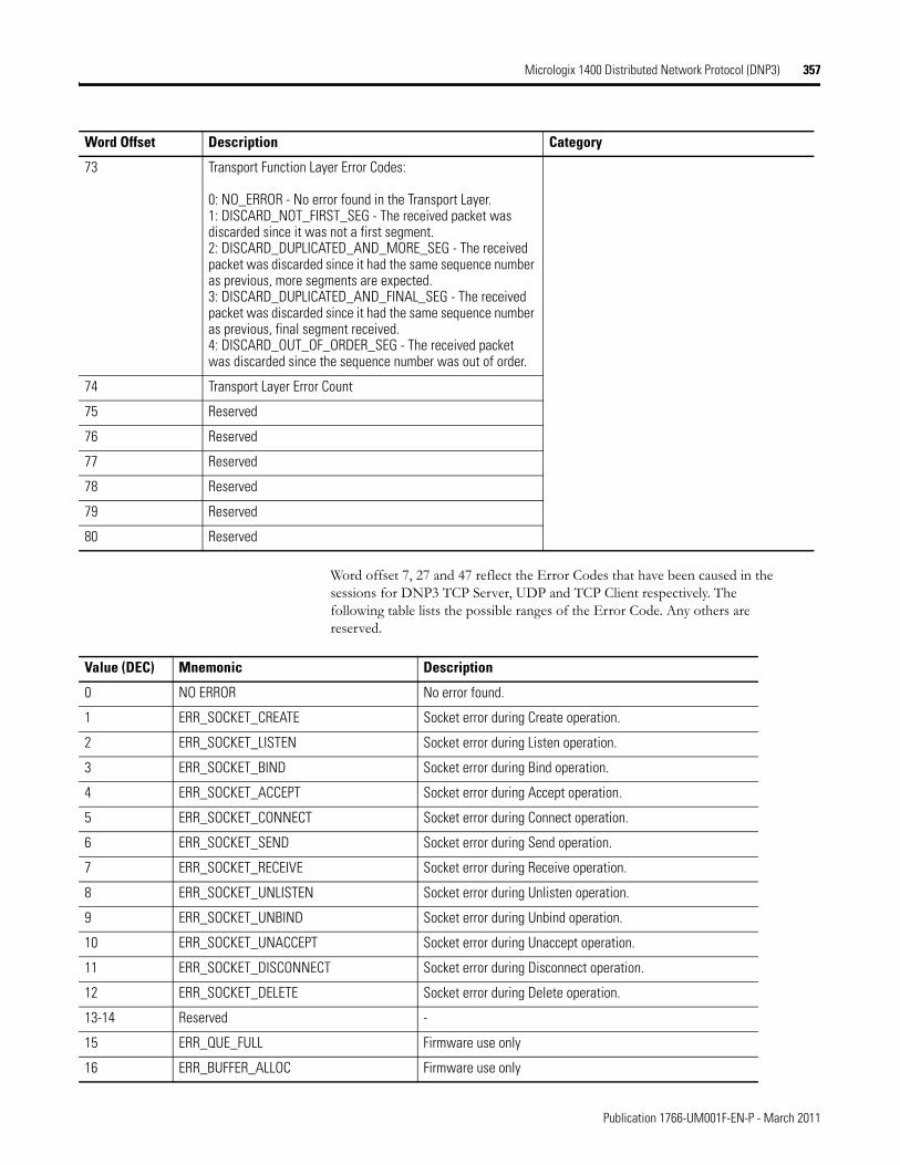
Micrologix 1400 Distributed Network Protocol (DNP3) 357
Word offset 7, 27 and 47 reflect the Error Codes that have been caused in the sessions for DNP3 TCP Server, UDP and TCP Client respectively. The following table lists the possible ranges of the Error Code. Any others are reserved.
73 Transport Function Layer Error Codes:
0: NO_ERROR - No error found in the Transport Layer.1: DISCARD_NOT_FIRST_SEG - The received packet was discarded since it was not a first segment.2: DISCARD_DUPLICATED_AND_MORE_SEG - The received packet was discarded since it had the same sequence number as previous, more segments are expected.3: DISCARD_DUPLICATED_AND_FINAL_SEG - The received packet was discarded since it had the same sequence number as previous, final segment received.4: DISCARD_OUT_OF_ORDER_SEG - The received packet was discarded since the sequence number was out of order.
74 Transport Layer Error Count
75 Reserved
76 Reserved
77 Reserved
78 Reserved
79 Reserved
80 Reserved
Word Offset Description Category
Value (DEC) Mnemonic Description
0 NO ERROR No error found.
1 ERR_SOCKET_CREATE Socket error during Create operation.
2 ERR_SOCKET_LISTEN Socket error during Listen operation.
3 ERR_SOCKET_BIND Socket error during Bind operation.
4 ERR_SOCKET_ACCEPT Socket error during Accept operation.
5 ERR_SOCKET_CONNECT Socket error during Connect operation.
6 ERR_SOCKET_SEND Socket error during Send operation.
7 ERR_SOCKET_RECEIVE Socket error during Receive operation.
8 ERR_SOCKET_UNLISTEN Socket error during Unlisten operation.
9 ERR_SOCKET_UNBIND Socket error during Unbind operation.
10 ERR_SOCKET_UNACCEPT Socket error during Unaccept operation.
11 ERR_SOCKET_DISCONNECT Socket error during Disconnect operation.
12 ERR_SOCKET_DELETE Socket error during Delete operation.
13-14 Reserved -
15 ERR_QUE_FULL Firmware use only
16 ERR_BUFFER_ALLOC Firmware use only
Publication 1766-UM001F-EN-P - March 2011
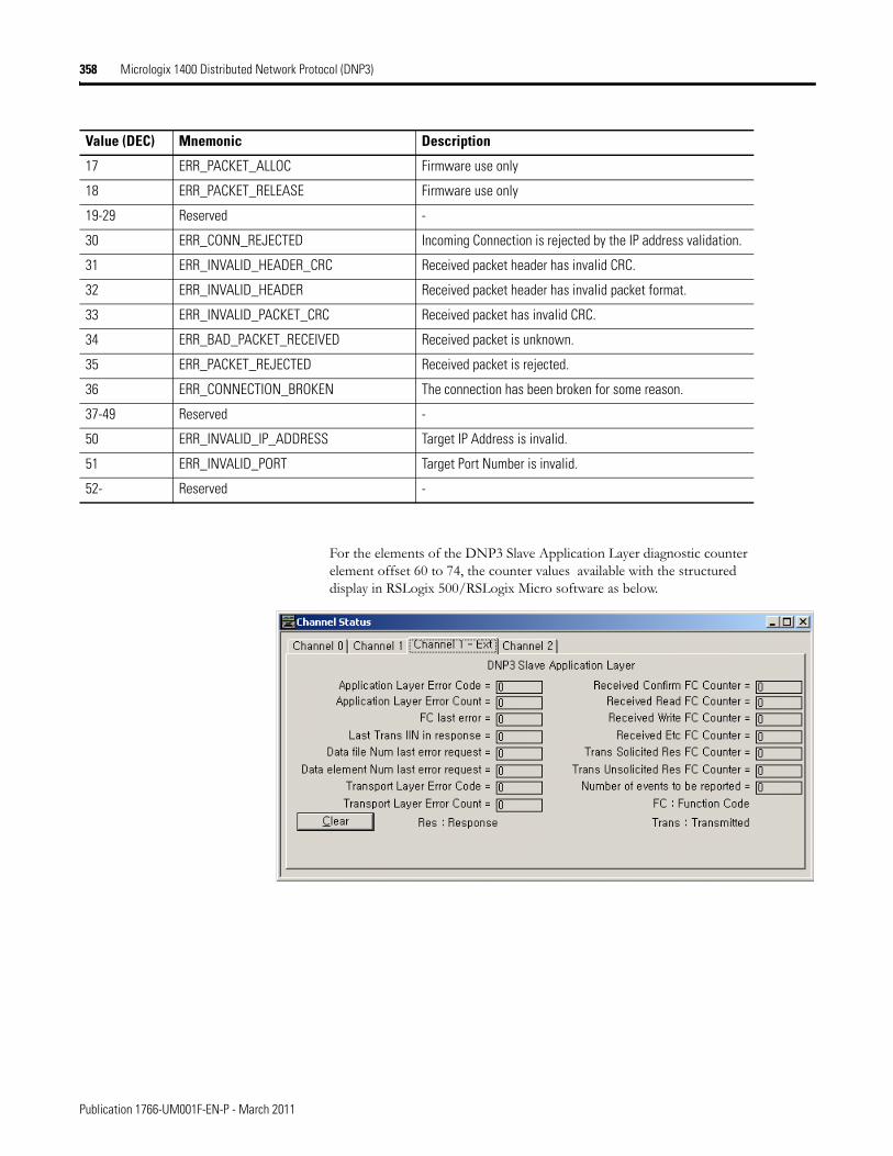
358 Micrologix 1400 Distributed Network Protocol (DNP3)
For the elements of the DNP3 Slave Application Layer diagnostic counter element offset 60 to 74, the counter values available with the structured display in RSLogix 500/RSLogix Micro software as below.
17 ERR_PACKET_ALLOC Firmware use only
18 ERR_PACKET_RELEASE Firmware use only
19-29 Reserved -
30 ERR_CONN_REJECTED Incoming Connection is rejected by the IP address validation.
31 ERR_INVALID_HEADER_CRC Received packet header has invalid CRC.
32 ERR_INVALID_HEADER Received packet header has invalid packet format.
33 ERR_INVALID_PACKET_CRC Received packet has invalid CRC.
34 ERR_BAD_PACKET_RECEIVED Received packet is unknown.
35 ERR_PACKET_REJECTED Received packet is rejected.
36 ERR_CONNECTION_BROKEN The connection has been broken for some reason.
37-49 Reserved -
50 ERR_INVALID_IP_ADDRESS Target IP Address is invalid.
51 ERR_INVALID_PORT Target Port Number is invalid.
52- Reserved -
Value (DEC) Mnemonic Description
Publication 1766-UM001F-EN-P - March 2011
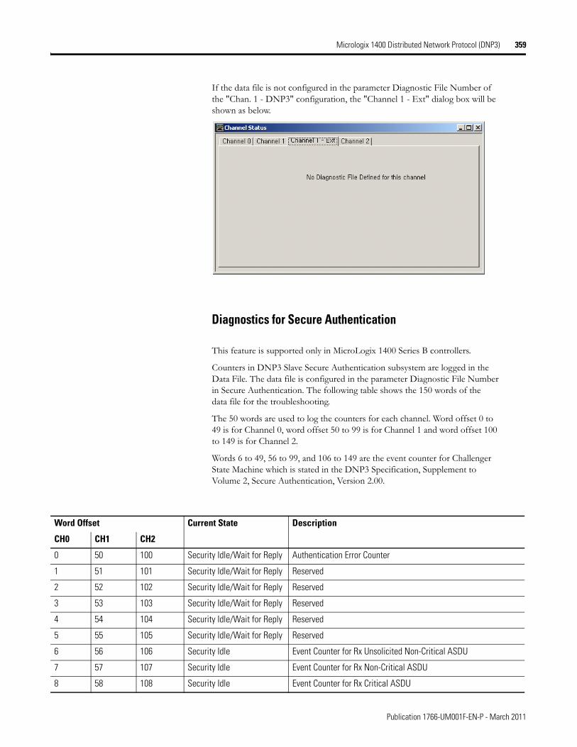
Micrologix 1400 Distributed Network Protocol (DNP3) 359
If the data file is not configured in the parameter Diagnostic File Number of the "Chan. 1 - DNP3" configuration, the "Channel 1 - Ext" dialog box will be shown as below.
Diagnostics for Secure Authentication
This feature is supported only in MicroLogix 1400 Series B controllers.
Counters in DNP3 Slave Secure Authentication subsystem are logged in the Data File. The data file is configured in the parameter Diagnostic File Number in Secure Authentication. The following table shows the 150 words of the data file for the troubleshooting.
The 50 words are used to log the counters for each channel. Word offset 0 to 49 is for Channel 0, word offset 50 to 99 is for Channel 1 and word offset 100 to 149 is for Channel 2.
Words 6 to 49, 56 to 99, and 106 to 149 are the event counter for Challenger State Machine which is stated in the DNP3 Specification, Supplement to Volume 2, Secure Authentication, Version 2.00.
Word Offset Current State Description
CH0 CH1 CH2
0 50 100 Security Idle/Wait for Reply Authentication Error Counter
1 51 101 Security Idle/Wait for Reply Reserved
2 52 102 Security Idle/Wait for Reply Reserved
3 53 103 Security Idle/Wait for Reply Reserved
4 54 104 Security Idle/Wait for Reply Reserved
5 55 105 Security Idle/Wait for Reply Reserved
6 56 106 Security Idle Event Counter for Rx Unsolicited Non-Critical ASDU
7 57 107 Security Idle Event Counter for Rx Non-Critical ASDU
8 58 108 Security Idle Event Counter for Rx Critical ASDU
Publication 1766-UM001F-EN-P - March 2011
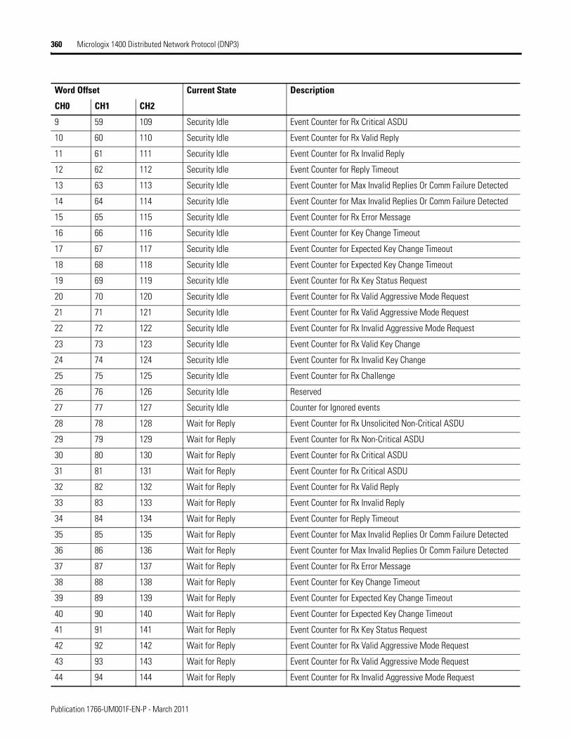
360 Micrologix 1400 Distributed Network Protocol (DNP3)
9 59 109 Security Idle Event Counter for Rx Critical ASDU
10 60 110 Security Idle Event Counter for Rx Valid Reply
11 61 111 Security Idle Event Counter for Rx Invalid Reply
12 62 112 Security Idle Event Counter for Reply Timeout
13 63 113 Security Idle Event Counter for Max Invalid Replies Or Comm Failure Detected
14 64 114 Security Idle Event Counter for Max Invalid Replies Or Comm Failure Detected
15 65 115 Security Idle Event Counter for Rx Error Message
16 66 116 Security Idle Event Counter for Key Change Timeout
17 67 117 Security Idle Event Counter for Expected Key Change Timeout
18 68 118 Security Idle Event Counter for Expected Key Change Timeout
19 69 119 Security Idle Event Counter for Rx Key Status Request
20 70 120 Security Idle Event Counter for Rx Valid Aggressive Mode Request
21 71 121 Security Idle Event Counter for Rx Valid Aggressive Mode Request
22 72 122 Security Idle Event Counter for Rx Invalid Aggressive Mode Request
23 73 123 Security Idle Event Counter for Rx Valid Key Change
24 74 124 Security Idle Event Counter for Rx Invalid Key Change
25 75 125 Security Idle Event Counter for Rx Challenge
26 76 126 Security Idle Reserved
27 77 127 Security Idle Counter for Ignored events
28 78 128 Wait for Reply Event Counter for Rx Unsolicited Non-Critical ASDU
29 79 129 Wait for Reply Event Counter for Rx Non-Critical ASDU
30 80 130 Wait for Reply Event Counter for Rx Critical ASDU
31 81 131 Wait for Reply Event Counter for Rx Critical ASDU
32 82 132 Wait for Reply Event Counter for Rx Valid Reply
33 83 133 Wait for Reply Event Counter for Rx Invalid Reply
34 84 134 Wait for Reply Event Counter for Reply Timeout
35 85 135 Wait for Reply Event Counter for Max Invalid Replies Or Comm Failure Detected
36 86 136 Wait for Reply Event Counter for Max Invalid Replies Or Comm Failure Detected
37 87 137 Wait for Reply Event Counter for Rx Error Message
38 88 138 Wait for Reply Event Counter for Key Change Timeout
39 89 139 Wait for Reply Event Counter for Expected Key Change Timeout
40 90 140 Wait for Reply Event Counter for Expected Key Change Timeout
41 91 141 Wait for Reply Event Counter for Rx Key Status Request
42 92 142 Wait for Reply Event Counter for Rx Valid Aggressive Mode Request
43 93 143 Wait for Reply Event Counter for Rx Valid Aggressive Mode Request
44 94 144 Wait for Reply Event Counter for Rx Invalid Aggressive Mode Request
Word Offset Current State Description
CH0 CH1 CH2
Publication 1766-UM001F-EN-P - March 2011
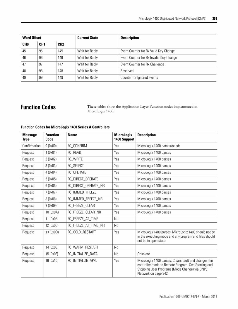
Micrologix 1400 Distributed Network Protocol (DNP3) 361
Function Codes These tables show the Application Layer Function codes implemented in MicroLogix 1400.
45 95 145 Wait for Reply Event Counter for Rx Valid Key Change
46 96 146 Wait for Reply Event Counter for Rx Invalid Key Change
47 97 147 Wait for Reply Event Counter for Rx Challenge
48 98 148 Wait for Reply Reserved
49 99 149 Wait for Reply Counter for Ignored events
Word Offset Current State Description
CH0 CH1 CH2
Function Codes for MicroLogix 1400 Series A Controllers
Message Type
Function Code
Name MicroLogix 1400 Support
Description
Confirmation 0 (0x00) FC_CONFIRM Yes MicroLogix 1400 parses/sends
Request 1 (0x01) FC_READ Yes MicroLogix 1400 parses
Request 2 (0x02) FC_WRITE Yes MicroLogix 1400 parses
Request 3 (0x03) FC_SELECT Yes MicroLogix 1400 parses
Request 4 (0x04) FC_OPERATE Yes MicroLogix 1400 parses
Request 5 (0x05) FC_DIRECT_OPERATE Yes MicroLogix 1400 parses
Request 6 (0x06) FC_DIRECT_OPERATE_NR Yes MicroLogix 1400 parses
Request 7 (0x07) FC_IMMED_FREEZE Yes MicroLogix 1400 parses
Request 8 (0x08) FC_IMMED_FREEZE_NR Yes MicroLogix 1400 parses
Request 9 (0x09) FC_FREEZE_CLEAR Yes MicroLogix 1400 parses
Request 10 (0x0A) FC_FREEZE_CLEAR_NR Yes MicroLogix 1400 parses
Request 11 (0x0B) FC_FREEZE_AT_TIME No
Request 12 (0x0C) FC_FREEZE_AT_TIME_NR No
Request 13 (0x0D) FC_COLD_RESTART Yes MicroLogix 1400 parses. MicroLogix 1400 should not be in the executing mode and any program and files should not be in open state.
Request 14 (0x0E) FC_WARM_RESTART No
Request 15 (0x0F) FC_INITIALIZE_DATA No Obsolete
Request 16 (0x10) FC_INITIALIZE_APPL Yes MicroLogix 1400 parses. Clears fault and changes the controller mode to Remote Program. See Starting and Stopping User Programs (Mode Change) via DNP3 Network on page 342.
Publication 1766-UM001F-EN-P - March 2011

362 Micrologix 1400 Distributed Network Protocol (DNP3)
Request 17 (0x11) FC_START_APPL Yes MicroLogix 1400 parses. Clears fault and changes the controller mode to Remote Run. See Starting and Stopping User Programs (Mode Change) via DNP3 Network on page 342.
Request 18 (0x12) FC_STOP_APPL Yes MicroLogix 1400 parses. Changes the controller mode to Remote Program. See Starting and Stopping User Programs (Mode Change) via DNP3 Network on page 342.
Request 19 (0x13) FC_SAVE_CONFIG No Deprecated.
Request 20 (0x14) FC_ENABLE_UNSOLICITED Yes MicroLogix 1400 parses
Request 21 (0x15) FC_DISABLE_UNSOLICITED Yes MicroLogix 1400 parses
Request 22 (0x16) FC_ASSIGN_CLASS No
Request 23 (0x17) FC_DELAY_MEASURE Yes MicroLogix 1400 parses. Used for non-LAN
Request 24 (0x18) FC_RECORD_CURRENT_TIME No Used for LAN
Request 25 (0x19) FC_OPEN_FILE Yes MicroLogix 1400 parses
Request 26 (0x1A) FC_CLOSE_FILE Yes MicroLogix 1400 parses
Request 27 (0x1B) FC_DELETE_FILE Yes MicroLogix 1400 parses
Request 28 (0x1C) FC_GET_FILE_INFO No
Request 29 (0x1D) FC_AUTHENTICATE_FILE Yes MicroLogix 1400 parses
Request 30 (0x1E) FC_ABORT_FILE No
Request 31 (0x1F) FC_ACTIVATE_CONFIG No
Request 32 (0x20) FC_AUTHENTICATE_REQ No
Request 33 (0x21) FC_AUTHENTICATE_ERR No
34 (0x22) to 128 (0x80)
No Reserved.
Response 129 (0x81) FC_RESPONSE Yes MicroLogix 1400 sends
Response 130 (0x82) FC_UNSOLICITED_RESPONSE Yes MicroLogix 1400 sends
Response 131 (0x83) FC_AUTHENTICATE_RESP No
132 (0x84) to 255 (0xFF)
No Reserved.
Function Codes for MicroLogix 1400 Series B Controllers
Message Type
Function Code
Name MicroLogix 1400 Support
Description
Confirmation 0 (0x00) FC_CONFIRM Yes MicroLogix 1400 parses/sends
Request 1 (0x01) FC_READ Yes MicroLogix 1400 parses
Request 2 (0x02) FC_WRITE Yes MicroLogix 1400 parses
Request 3 (0x03) FC_SELECT Yes MicroLogix 1400 parses
Request 4 (0x04) FC_OPERATE Yes MicroLogix 1400 parses
Function Codes for MicroLogix 1400 Series A Controllers
Message Type
Function Code
Name MicroLogix 1400 Support
Description
Publication 1766-UM001F-EN-P - March 2011
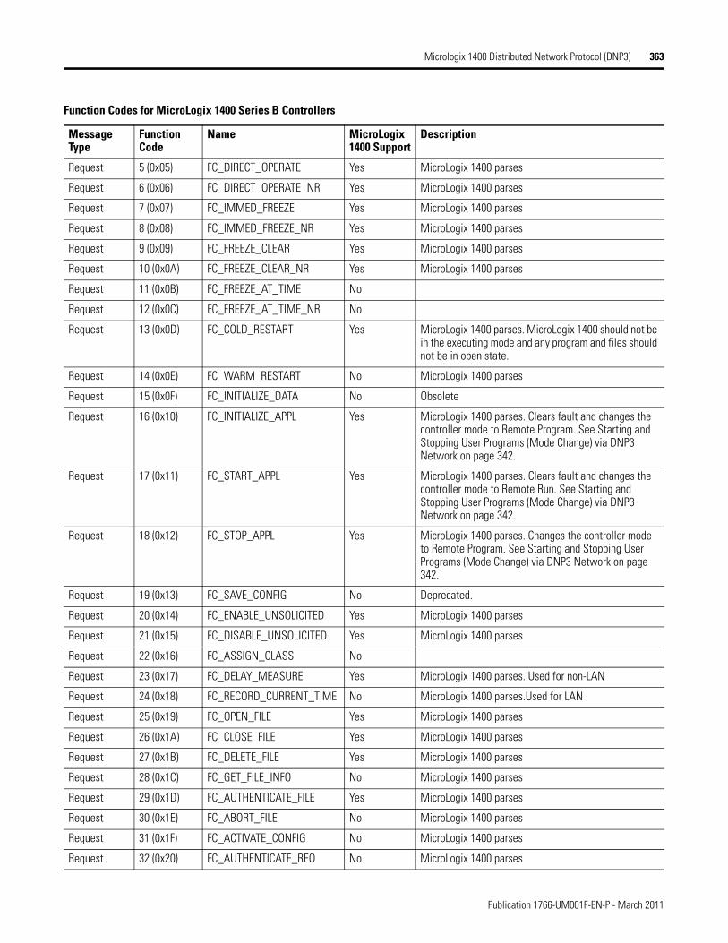
Micrologix 1400 Distributed Network Protocol (DNP3) 363
Request 5 (0x05) FC_DIRECT_OPERATE Yes MicroLogix 1400 parses
Request 6 (0x06) FC_DIRECT_OPERATE_NR Yes MicroLogix 1400 parses
Request 7 (0x07) FC_IMMED_FREEZE Yes MicroLogix 1400 parses
Request 8 (0x08) FC_IMMED_FREEZE_NR Yes MicroLogix 1400 parses
Request 9 (0x09) FC_FREEZE_CLEAR Yes MicroLogix 1400 parses
Request 10 (0x0A) FC_FREEZE_CLEAR_NR Yes MicroLogix 1400 parses
Request 11 (0x0B) FC_FREEZE_AT_TIME No
Request 12 (0x0C) FC_FREEZE_AT_TIME_NR No
Request 13 (0x0D) FC_COLD_RESTART Yes MicroLogix 1400 parses. MicroLogix 1400 should not be in the executing mode and any program and files should not be in open state.
Request 14 (0x0E) FC_WARM_RESTART No MicroLogix 1400 parses
Request 15 (0x0F) FC_INITIALIZE_DATA No Obsolete
Request 16 (0x10) FC_INITIALIZE_APPL Yes MicroLogix 1400 parses. Clears fault and changes the controller mode to Remote Program. See Starting and Stopping User Programs (Mode Change) via DNP3 Network on page 342.
Request 17 (0x11) FC_START_APPL Yes MicroLogix 1400 parses. Clears fault and changes the controller mode to Remote Run. See Starting and Stopping User Programs (Mode Change) via DNP3 Network on page 342.
Request 18 (0x12) FC_STOP_APPL Yes MicroLogix 1400 parses. Changes the controller mode to Remote Program. See Starting and Stopping User Programs (Mode Change) via DNP3 Network on page 342.
Request 19 (0x13) FC_SAVE_CONFIG No Deprecated.
Request 20 (0x14) FC_ENABLE_UNSOLICITED Yes MicroLogix 1400 parses
Request 21 (0x15) FC_DISABLE_UNSOLICITED Yes MicroLogix 1400 parses
Request 22 (0x16) FC_ASSIGN_CLASS No
Request 23 (0x17) FC_DELAY_MEASURE Yes MicroLogix 1400 parses. Used for non-LAN
Request 24 (0x18) FC_RECORD_CURRENT_TIME No MicroLogix 1400 parses.Used for LAN
Request 25 (0x19) FC_OPEN_FILE Yes MicroLogix 1400 parses
Request 26 (0x1A) FC_CLOSE_FILE Yes MicroLogix 1400 parses
Request 27 (0x1B) FC_DELETE_FILE Yes MicroLogix 1400 parses
Request 28 (0x1C) FC_GET_FILE_INFO No MicroLogix 1400 parses
Request 29 (0x1D) FC_AUTHENTICATE_FILE Yes MicroLogix 1400 parses
Request 30 (0x1E) FC_ABORT_FILE No MicroLogix 1400 parses
Request 31 (0x1F) FC_ACTIVATE_CONFIG No MicroLogix 1400 parses
Request 32 (0x20) FC_AUTHENTICATE_REQ No MicroLogix 1400 parses
Function Codes for MicroLogix 1400 Series B Controllers
Message Type
Function Code
Name MicroLogix 1400 Support
Description
Publication 1766-UM001F-EN-P - March 2011
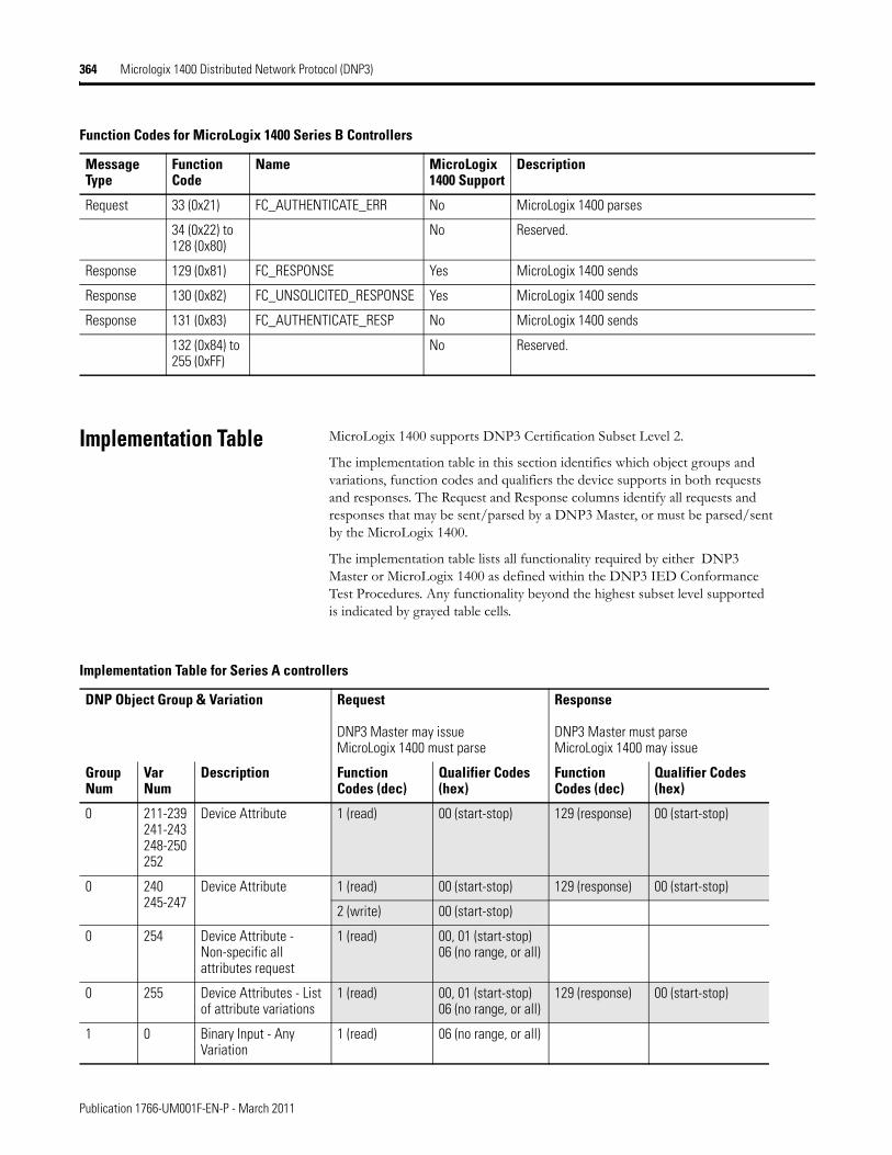
364 Micrologix 1400 Distributed Network Protocol (DNP3)
Implementation Table MicroLogix 1400 supports DNP3 Certification Subset Level 2.
The implementation table in this section identifies which object groups and variations, function codes and qualifiers the device supports in both requests and responses. The Request and Response columns identify all requests and responses that may be sent/parsed by a DNP3 Master, or must be parsed/sent by the MicroLogix 1400.
The implementation table lists all functionality required by either DNP3 Master or MicroLogix 1400 as defined within the DNP3 IED Conformance Test Procedures. Any functionality beyond the highest subset level supported is indicated by grayed table cells.
Request 33 (0x21) FC_AUTHENTICATE_ERR No MicroLogix 1400 parses
34 (0x22) to 128 (0x80)
No Reserved.
Response 129 (0x81) FC_RESPONSE Yes MicroLogix 1400 sends
Response 130 (0x82) FC_UNSOLICITED_RESPONSE Yes MicroLogix 1400 sends
Response 131 (0x83) FC_AUTHENTICATE_RESP No MicroLogix 1400 sends
132 (0x84) to 255 (0xFF)
No Reserved.
Function Codes for MicroLogix 1400 Series B Controllers
Message Type
Function Code
Name MicroLogix 1400 Support
Description
Implementation Table for Series A controllers
DNP Object Group & Variation Request
DNP3 Master may issueMicroLogix 1400 must parse
Response
DNP3 Master must parseMicroLogix 1400 may issue
Group Num
Var Num
Description Function Codes (dec)
Qualifier Codes (hex)
Function Codes (dec)
Qualifier Codes (hex)
0 211-239241-243248-250252
Device Attribute 1 (read) 00 (start-stop) 129 (response) 00 (start-stop)
0 240245-247
Device Attribute 1 (read) 00 (start-stop) 129 (response) 00 (start-stop)
2 (write) 00 (start-stop)
0 254 Device Attribute - Non-specific all attributes request
1 (read) 00, 01 (start-stop)06 (no range, or all)
0 255 Device Attributes - List of attribute variations
1 (read) 00, 01 (start-stop)06 (no range, or all)
129 (response) 00 (start-stop)
1 0 Binary Input - Any Variation
1 (read) 06 (no range, or all)
Publication 1766-UM001F-EN-P - March 2011
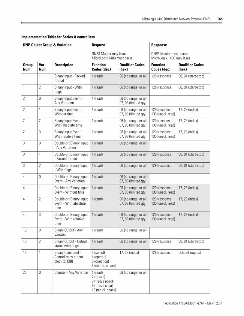
Micrologix 1400 Distributed Network Protocol (DNP3) 365
1 1 Binary Input - Packed format
1 (read) 06 (no range, or all) 129 (response) 00, 01 (start-stop)
1 2 Binary Input - With flags
1 (read) 06 (no range, or all) 129 (response) 00, 01 (start-stop)
2 0 Binary Input Event - Any Variation
1 (read) 06 (no range, or all)07, 08 (limited qty)
2 1 Binary Input Event - Without time
1 (read) 06 (no range, or all)07, 08 (limited qty)
129 (response)130 (unsol. resp)
17, 28 (index)
2 2 Binary Input Event - With absolute time
1 (read) 06 (no range, or all)07, 08 (limited qty)
129 (response)130 (unsol. resp)
17, 28 (index)
2 3 Binary Input Event - With relative time
1 (read) 06 (no range, or all)07, 08 (limited qty)
129 (response)130 (unsol. resp)
17, 28 (index)
3 0 Double-bit Binary Input - Any Variation
1 (read) 06 (no range, or all)
3 1 Double-bit Binary Input - Packed format
1 (read) 06 (no range, or all) 129 (response) 00, 01 (start-stop)
3 2 Double-bit Binary Input - With flags
1 (read) 06 (no range, or all) 129 (response) 00, 01 (start-stop)
4 0 Double-bit Binary Input Event - Any Variation
1 (read) 06 (no range, or all)07, 08 (limited qty)
4 1 Double-bit Binary Input Event - Without time
1 (read) 06 (no range, or all)07, 08 (limited qty)
129 (response)130 (unsol. resp)
17, 28 (index)
4 2 Double-bit Binary Input Event - With absolute time
1 (read) 06 (no range, or all)07, 08 (limited qty)
129 (response)130 (unsol. resp)
17, 28 (index)
4 3 Double-bit Binary Input Event - With relative time
1 (read) 06 (no range, or all)07, 08 (limited qty)
129 (response)130 (unsol. resp)
17, 28 (index)
10 0 Binary Output - Any Variation
1 (read) 06 (no range, or all)
10 2 Binary Output - Output status with flags
1 (read) 06 (no range, or all) 129 (response) 00, 01 (start-stop)
12 1 Binary Command - Control relay output block (CROB)
3 (select)4 (operate)5 (direct op)6 (dir. op, no ack)
17, 28 (index) 129 (response) echo of request
20 0 Counter - Any Variation 1 (read)7 (freeze)8 (freeze noack)9 (freeze clear)10 (frz. cl. noack)
06 (no range, or all)
Implementation Table for Series A controllers
DNP Object Group & Variation Request
DNP3 Master may issueMicroLogix 1400 must parse
Response
DNP3 Master must parseMicroLogix 1400 may issue
Group Num
Var Num
Description Function Codes (dec)
Qualifier Codes (hex)
Function Codes (dec)
Qualifier Codes (hex)
Publication 1766-UM001F-EN-P - March 2011
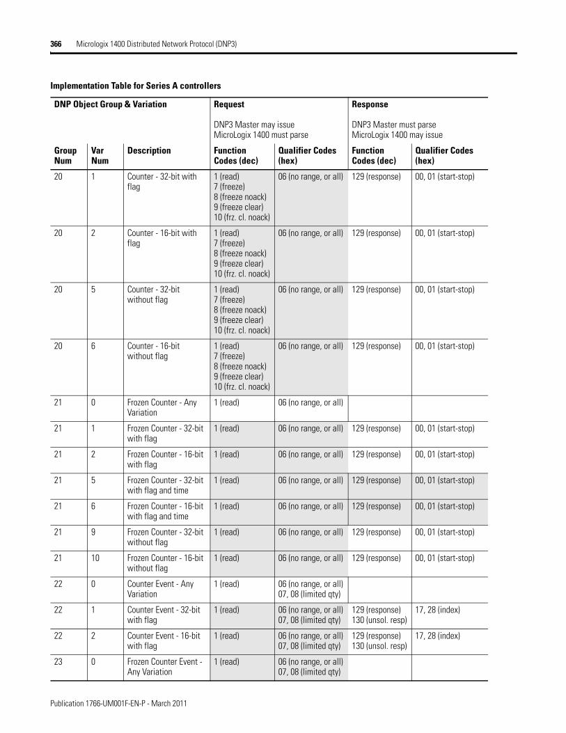
366 Micrologix 1400 Distributed Network Protocol (DNP3)
20 1 Counter - 32-bit with flag
1 (read)7 (freeze)8 (freeze noack)9 (freeze clear)10 (frz. cl. noack)
06 (no range, or all) 129 (response) 00, 01 (start-stop)
20 2 Counter - 16-bit with flag
1 (read)7 (freeze)8 (freeze noack)9 (freeze clear)10 (frz. cl. noack)
06 (no range, or all) 129 (response) 00, 01 (start-stop)
20 5 Counter - 32-bit without flag
1 (read)7 (freeze)8 (freeze noack)9 (freeze clear)10 (frz. cl. noack)
06 (no range, or all) 129 (response) 00, 01 (start-stop)
20 6 Counter - 16-bit without flag
1 (read)7 (freeze)8 (freeze noack)9 (freeze clear)10 (frz. cl. noack)
06 (no range, or all) 129 (response) 00, 01 (start-stop)
21 0 Frozen Counter - Any Variation
1 (read) 06 (no range, or all)
21 1 Frozen Counter - 32-bit with flag
1 (read) 06 (no range, or all) 129 (response) 00, 01 (start-stop)
21 2 Frozen Counter - 16-bit with flag
1 (read) 06 (no range, or all) 129 (response) 00, 01 (start-stop)
21 5 Frozen Counter - 32-bit with flag and time
1 (read) 06 (no range, or all) 129 (response) 00, 01 (start-stop)
21 6 Frozen Counter - 16-bit with flag and time
1 (read) 06 (no range, or all) 129 (response) 00, 01 (start-stop)
21 9 Frozen Counter - 32-bit without flag
1 (read) 06 (no range, or all) 129 (response) 00, 01 (start-stop)
21 10 Frozen Counter - 16-bit without flag
1 (read) 06 (no range, or all) 129 (response) 00, 01 (start-stop)
22 0 Counter Event - Any Variation
1 (read) 06 (no range, or all)07, 08 (limited qty)
22 1 Counter Event - 32-bit with flag
1 (read) 06 (no range, or all)07, 08 (limited qty)
129 (response)130 (unsol. resp)
17, 28 (index)
22 2 Counter Event - 16-bit with flag
1 (read) 06 (no range, or all)07, 08 (limited qty)
129 (response)130 (unsol. resp)
17, 28 (index)
23 0 Frozen Counter Event - Any Variation
1 (read) 06 (no range, or all)07, 08 (limited qty)
Implementation Table for Series A controllers
DNP Object Group & Variation Request
DNP3 Master may issueMicroLogix 1400 must parse
Response
DNP3 Master must parseMicroLogix 1400 may issue
Group Num
Var Num
Description Function Codes (dec)
Qualifier Codes (hex)
Function Codes (dec)
Qualifier Codes (hex)
Publication 1766-UM001F-EN-P - March 2011
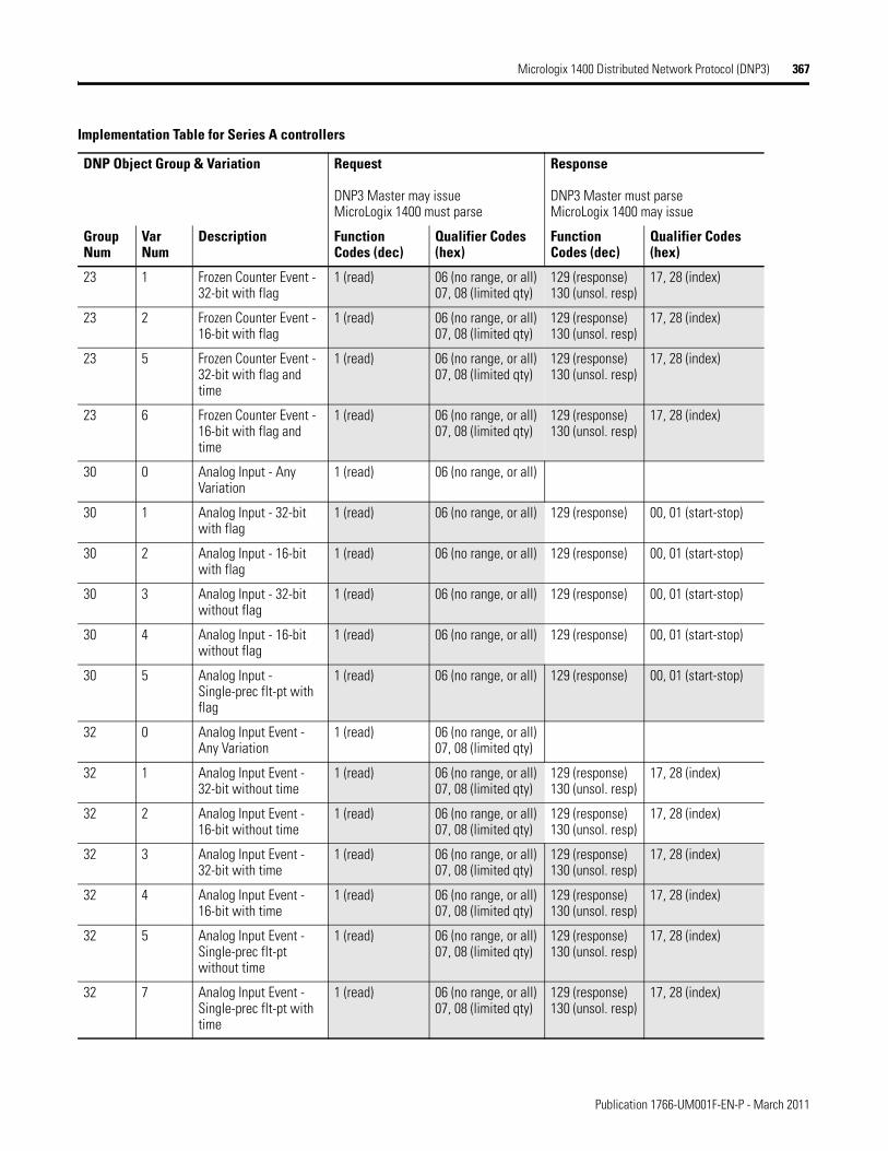
Micrologix 1400 Distributed Network Protocol (DNP3) 367
23 1 Frozen Counter Event - 32-bit with flag
1 (read) 06 (no range, or all)07, 08 (limited qty)
129 (response)130 (unsol. resp)
17, 28 (index)
23 2 Frozen Counter Event - 16-bit with flag
1 (read) 06 (no range, or all)07, 08 (limited qty)
129 (response)130 (unsol. resp)
17, 28 (index)
23 5 Frozen Counter Event - 32-bit with flag and time
1 (read) 06 (no range, or all)07, 08 (limited qty)
129 (response)130 (unsol. resp)
17, 28 (index)
23 6 Frozen Counter Event - 16-bit with flag and time
1 (read) 06 (no range, or all)07, 08 (limited qty)
129 (response)130 (unsol. resp)
17, 28 (index)
30 0 Analog Input - Any Variation
1 (read) 06 (no range, or all)
30 1 Analog Input - 32-bit with flag
1 (read) 06 (no range, or all) 129 (response) 00, 01 (start-stop)
30 2 Analog Input - 16-bit with flag
1 (read) 06 (no range, or all) 129 (response) 00, 01 (start-stop)
30 3 Analog Input - 32-bit without flag
1 (read) 06 (no range, or all) 129 (response) 00, 01 (start-stop)
30 4 Analog Input - 16-bit without flag
1 (read) 06 (no range, or all) 129 (response) 00, 01 (start-stop)
30 5 Analog Input - Single-prec flt-pt with flag
1 (read) 06 (no range, or all) 129 (response) 00, 01 (start-stop)
32 0 Analog Input Event - Any Variation
1 (read) 06 (no range, or all)07, 08 (limited qty)
32 1 Analog Input Event - 32-bit without time
1 (read) 06 (no range, or all)07, 08 (limited qty)
129 (response)130 (unsol. resp)
17, 28 (index)
32 2 Analog Input Event - 16-bit without time
1 (read) 06 (no range, or all)07, 08 (limited qty)
129 (response)130 (unsol. resp)
17, 28 (index)
32 3 Analog Input Event - 32-bit with time
1 (read) 06 (no range, or all)07, 08 (limited qty)
129 (response)130 (unsol. resp)
17, 28 (index)
32 4 Analog Input Event - 16-bit with time
1 (read) 06 (no range, or all)07, 08 (limited qty)
129 (response)130 (unsol. resp)
17, 28 (index)
32 5 Analog Input Event - Single-prec flt-pt without time
1 (read) 06 (no range, or all)07, 08 (limited qty)
129 (response)130 (unsol. resp)
17, 28 (index)
32 7 Analog Input Event - Single-prec flt-pt with time
1 (read) 06 (no range, or all)07, 08 (limited qty)
129 (response)130 (unsol. resp)
17, 28 (index)
Implementation Table for Series A controllers
DNP Object Group & Variation Request
DNP3 Master may issueMicroLogix 1400 must parse
Response
DNP3 Master must parseMicroLogix 1400 may issue
Group Num
Var Num
Description Function Codes (dec)
Qualifier Codes (hex)
Function Codes (dec)
Qualifier Codes (hex)
Publication 1766-UM001F-EN-P - March 2011
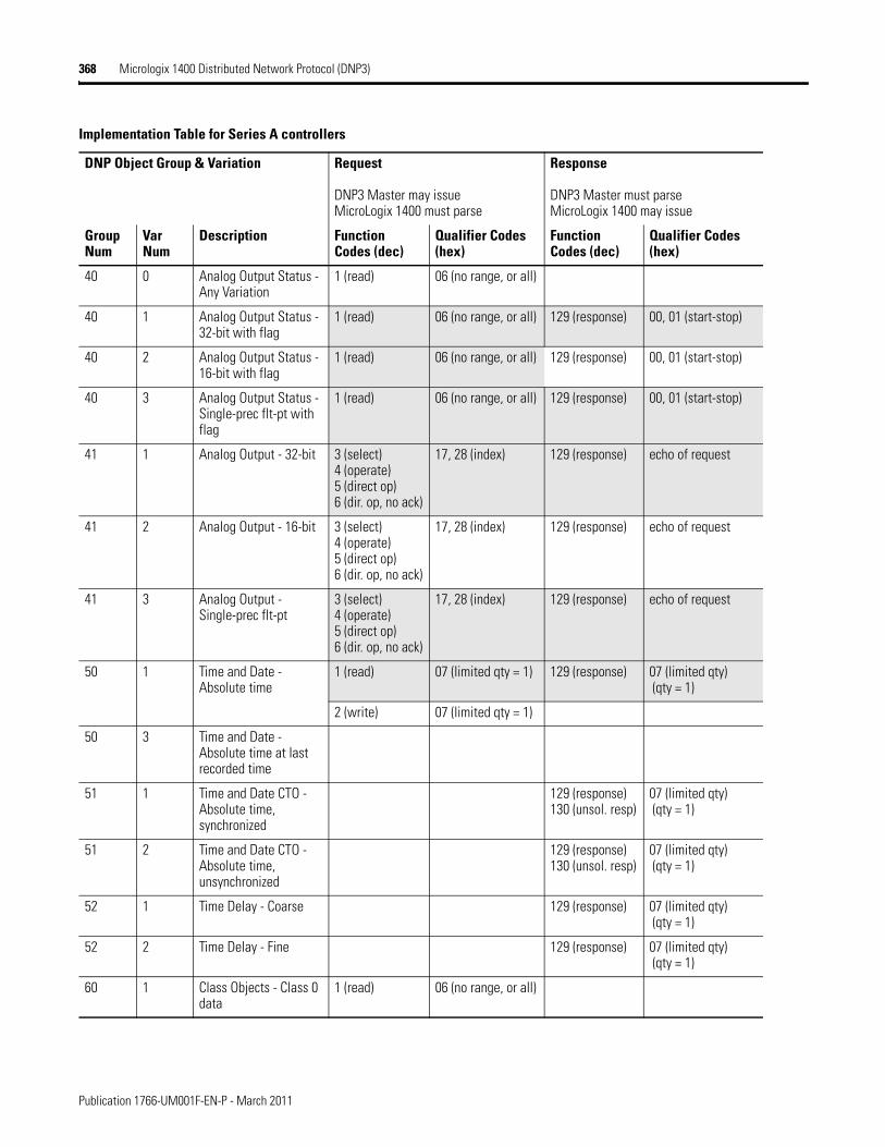
368 Micrologix 1400 Distributed Network Protocol (DNP3)
40 0 Analog Output Status - Any Variation
1 (read) 06 (no range, or all)
40 1 Analog Output Status - 32-bit with flag
1 (read) 06 (no range, or all) 129 (response) 00, 01 (start-stop)
40 2 Analog Output Status - 16-bit with flag
1 (read) 06 (no range, or all) 129 (response) 00, 01 (start-stop)
40 3 Analog Output Status - Single-prec flt-pt with flag
1 (read) 06 (no range, or all) 129 (response) 00, 01 (start-stop)
41 1 Analog Output - 32-bit 3 (select)4 (operate)5 (direct op)6 (dir. op, no ack)
17, 28 (index) 129 (response) echo of request
41 2 Analog Output - 16-bit 3 (select)4 (operate)5 (direct op)6 (dir. op, no ack)
17, 28 (index) 129 (response) echo of request
41 3 Analog Output - Single-prec flt-pt
3 (select)4 (operate)5 (direct op)6 (dir. op, no ack)
17, 28 (index) 129 (response) echo of request
50 1 Time and Date - Absolute time
1 (read) 07 (limited qty = 1) 129 (response) 07 (limited qty) (qty = 1)
2 (write) 07 (limited qty = 1)
50 3 Time and Date - Absolute time at last recorded time
51 1 Time and Date CTO - Absolute time, synchronized
129 (response)130 (unsol. resp)
07 (limited qty) (qty = 1)
51 2 Time and Date CTO - Absolute time, unsynchronized
129 (response)130 (unsol. resp)
07 (limited qty) (qty = 1)
52 1 Time Delay - Coarse 129 (response) 07 (limited qty) (qty = 1)
52 2 Time Delay - Fine 129 (response) 07 (limited qty) (qty = 1)
60 1 Class Objects - Class 0 data
1 (read) 06 (no range, or all)
Implementation Table for Series A controllers
DNP Object Group & Variation Request
DNP3 Master may issueMicroLogix 1400 must parse
Response
DNP3 Master must parseMicroLogix 1400 may issue
Group Num
Var Num
Description Function Codes (dec)
Qualifier Codes (hex)
Function Codes (dec)
Qualifier Codes (hex)
Publication 1766-UM001F-EN-P - March 2011
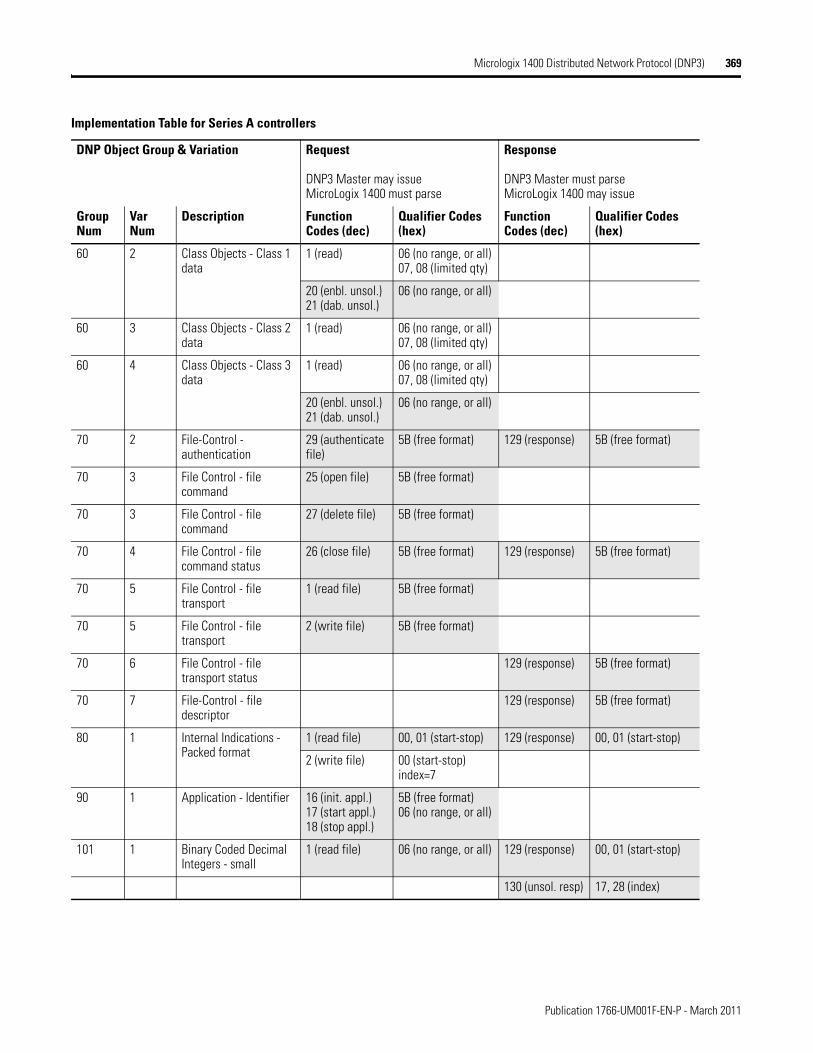
Micrologix 1400 Distributed Network Protocol (DNP3) 369
60 2 Class Objects - Class 1 data
1 (read) 06 (no range, or all)07, 08 (limited qty)
20 (enbl. unsol.)21 (dab. unsol.)
06 (no range, or all)
60 3 Class Objects - Class 2 data
1 (read) 06 (no range, or all)07, 08 (limited qty)
60 4 Class Objects - Class 3 data
1 (read) 06 (no range, or all)07, 08 (limited qty)
20 (enbl. unsol.)21 (dab. unsol.)
06 (no range, or all)
70 2 File-Control - authentication
29 (authenticate file)
5B (free format) 129 (response) 5B (free format)
70 3 File Control - file command
25 (open file) 5B (free format)
70 3 File Control - file command
27 (delete file) 5B (free format)
70 4 File Control - file command status
26 (close file) 5B (free format) 129 (response) 5B (free format)
70 5 File Control - file transport
1 (read file) 5B (free format)
70 5 File Control - file transport
2 (write file) 5B (free format)
70 6 File Control - file transport status
129 (response) 5B (free format)
70 7 File-Control - file descriptor
129 (response) 5B (free format)
80 1 Internal Indications - Packed format
1 (read file) 00, 01 (start-stop) 129 (response) 00, 01 (start-stop)
2 (write file) 00 (start-stop)index=7
90 1 Application - Identifier 16 (init. appl.)17 (start appl.)18 (stop appl.)
5B (free format)06 (no range, or all)
101 1 Binary Coded Decimal Integers - small
1 (read file) 06 (no range, or all) 129 (response) 00, 01 (start-stop)
130 (unsol. resp) 17, 28 (index)
Implementation Table for Series A controllers
DNP Object Group & Variation Request
DNP3 Master may issueMicroLogix 1400 must parse
Response
DNP3 Master must parseMicroLogix 1400 may issue
Group Num
Var Num
Description Function Codes (dec)
Qualifier Codes (hex)
Function Codes (dec)
Qualifier Codes (hex)
Publication 1766-UM001F-EN-P - March 2011
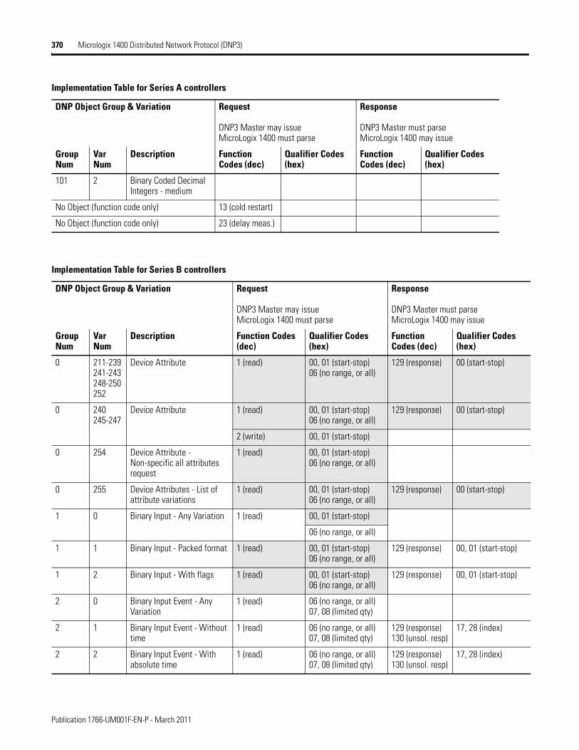
370 Micrologix 1400 Distributed Network Protocol (DNP3)
101 2 Binary Coded Decimal Integers - medium
No Object (function code only) 13 (cold restart)
No Object (function code only) 23 (delay meas.)
Implementation Table for Series A controllers
DNP Object Group & Variation Request
DNP3 Master may issueMicroLogix 1400 must parse
Response
DNP3 Master must parseMicroLogix 1400 may issue
Group Num
Var Num
Description Function Codes (dec)
Qualifier Codes (hex)
Function Codes (dec)
Qualifier Codes (hex)
Implementation Table for Series B controllers
DNP Object Group & Variation Request
DNP3 Master may issueMicroLogix 1400 must parse
Response
DNP3 Master must parseMicroLogix 1400 may issue
Group Num
Var Num
Description Function Codes (dec)
Qualifier Codes (hex)
Function Codes (dec)
Qualifier Codes (hex)
0 211-239241-243248-250252
Device Attribute 1 (read) 00, 01 (start-stop)06 (no range, or all)
129 (response) 00 (start-stop)
0 240245-247
Device Attribute 1 (read) 00, 01 (start-stop)06 (no range, or all)
129 (response) 00 (start-stop)
2 (write) 00, 01 (start-stop)
0 254 Device Attribute - Non-specific all attributes request
1 (read) 00, 01 (start-stop)06 (no range, or all)
0 255 Device Attributes - List of attribute variations
1 (read) 00, 01 (start-stop)06 (no range, or all)
129 (response) 00 (start-stop)
1 0 Binary Input - Any Variation 1 (read) 00, 01 (start-stop)
06 (no range, or all)
1 1 Binary Input - Packed format 1 (read) 00, 01 (start-stop)06 (no range, or all)
129 (response) 00, 01 (start-stop)
1 2 Binary Input - With flags 1 (read) 00, 01 (start-stop)06 (no range, or all)
129 (response) 00, 01 (start-stop)
2 0 Binary Input Event - Any Variation
1 (read) 06 (no range, or all)07, 08 (limited qty)
2 1 Binary Input Event - Without time
1 (read) 06 (no range, or all)07, 08 (limited qty)
129 (response)130 (unsol. resp)
17, 28 (index)
2 2 Binary Input Event - With absolute time
1 (read) 06 (no range, or all)07, 08 (limited qty)
129 (response)130 (unsol. resp)
17, 28 (index)
Publication 1766-UM001F-EN-P - March 2011
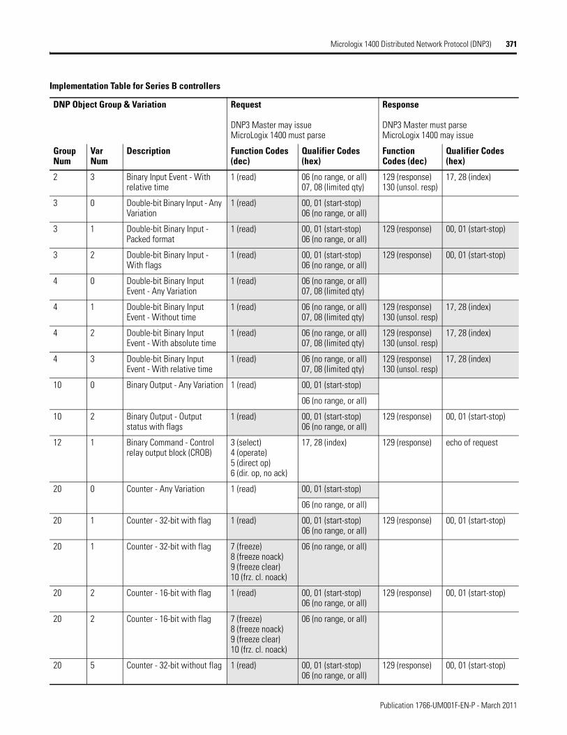
Micrologix 1400 Distributed Network Protocol (DNP3) 371
2 3 Binary Input Event - With relative time
1 (read) 06 (no range, or all)07, 08 (limited qty)
129 (response)130 (unsol. resp)
17, 28 (index)
3 0 Double-bit Binary Input - Any Variation
1 (read) 00, 01 (start-stop)06 (no range, or all)
3 1 Double-bit Binary Input - Packed format
1 (read) 00, 01 (start-stop)06 (no range, or all)
129 (response) 00, 01 (start-stop)
3 2 Double-bit Binary Input - With flags
1 (read) 00, 01 (start-stop)06 (no range, or all)
129 (response) 00, 01 (start-stop)
4 0 Double-bit Binary Input Event - Any Variation
1 (read) 06 (no range, or all)07, 08 (limited qty)
4 1 Double-bit Binary Input Event - Without time
1 (read) 06 (no range, or all)07, 08 (limited qty)
129 (response)130 (unsol. resp)
17, 28 (index)
4 2 Double-bit Binary Input Event - With absolute time
1 (read) 06 (no range, or all)07, 08 (limited qty)
129 (response)130 (unsol. resp)
17, 28 (index)
4 3 Double-bit Binary Input Event - With relative time
1 (read) 06 (no range, or all)07, 08 (limited qty)
129 (response)130 (unsol. resp)
17, 28 (index)
10 0 Binary Output - Any Variation 1 (read) 00, 01 (start-stop)
06 (no range, or all)
10 2 Binary Output - Output status with flags
1 (read) 00, 01 (start-stop)06 (no range, or all)
129 (response) 00, 01 (start-stop)
12 1 Binary Command - Control relay output block (CROB)
3 (select)4 (operate)5 (direct op)6 (dir. op, no ack)
17, 28 (index) 129 (response) echo of request
20 0 Counter - Any Variation 1 (read) 00, 01 (start-stop)
06 (no range, or all)
20 1 Counter - 32-bit with flag 1 (read) 00, 01 (start-stop)06 (no range, or all)
129 (response) 00, 01 (start-stop)
20 1 Counter - 32-bit with flag 7 (freeze)8 (freeze noack)9 (freeze clear)10 (frz. cl. noack)
06 (no range, or all)
20 2 Counter - 16-bit with flag 1 (read) 00, 01 (start-stop)06 (no range, or all)
129 (response) 00, 01 (start-stop)
20 2 Counter - 16-bit with flag 7 (freeze)8 (freeze noack)9 (freeze clear)10 (frz. cl. noack)
06 (no range, or all)
20 5 Counter - 32-bit without flag 1 (read) 00, 01 (start-stop)06 (no range, or all)
129 (response) 00, 01 (start-stop)
Implementation Table for Series B controllers
DNP Object Group & Variation Request
DNP3 Master may issueMicroLogix 1400 must parse
Response
DNP3 Master must parseMicroLogix 1400 may issue
Group Num
Var Num
Description Function Codes (dec)
Qualifier Codes (hex)
Function Codes (dec)
Qualifier Codes (hex)
Publication 1766-UM001F-EN-P - March 2011
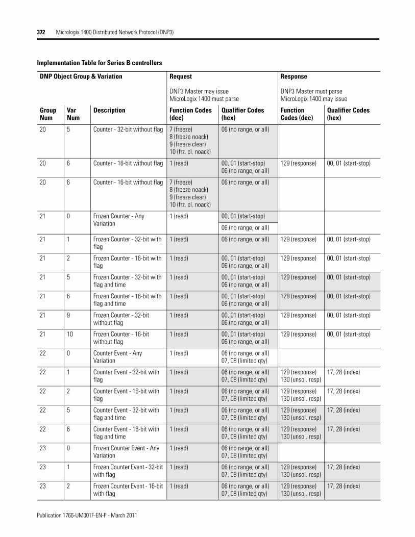
372 Micrologix 1400 Distributed Network Protocol (DNP3)
20 5 Counter - 32-bit without flag 7 (freeze)8 (freeze noack)9 (freeze clear)10 (frz. cl. noack)
06 (no range, or all)
20 6 Counter - 16-bit without flag 1 (read) 00, 01 (start-stop)06 (no range, or all)
129 (response) 00, 01 (start-stop)
20 6 Counter - 16-bit without flag 7 (freeze)8 (freeze noack)9 (freeze clear)10 (frz. cl. noack)
06 (no range, or all)
21 0 Frozen Counter - Any Variation
1 (read) 00, 01 (start-stop)
06 (no range, or all)
21 1 Frozen Counter - 32-bit with flag
1 (read) 06 (no range, or all) 129 (response) 00, 01 (start-stop)
21 2 Frozen Counter - 16-bit with flag
1 (read) 00, 01 (start-stop)06 (no range, or all)
129 (response) 00, 01 (start-stop)
21 5 Frozen Counter - 32-bit with flag and time
1 (read) 00, 01 (start-stop)06 (no range, or all)
129 (response) 00, 01 (start-stop)
21 6 Frozen Counter - 16-bit with flag and time
1 (read) 00, 01 (start-stop)06 (no range, or all)
129 (response) 00, 01 (start-stop)
21 9 Frozen Counter - 32-bit without flag
1 (read) 00, 01 (start-stop)06 (no range, or all)
129 (response) 00, 01 (start-stop)
21 10 Frozen Counter - 16-bit without flag
1 (read) 00, 01 (start-stop)06 (no range, or all)
129 (response) 00, 01 (start-stop)
22 0 Counter Event - Any Variation
1 (read) 06 (no range, or all)07, 08 (limited qty)
22 1 Counter Event - 32-bit with flag
1 (read) 06 (no range, or all)07, 08 (limited qty)
129 (response)130 (unsol. resp)
17, 28 (index)
22 2 Counter Event - 16-bit with flag
1 (read) 06 (no range, or all)07, 08 (limited qty)
129 (response)130 (unsol. resp)
17, 28 (index)
22 5 Counter Event - 32-bit with flag and time
1 (read) 06 (no range, or all)07, 08 (limited qty)
129 (response)130 (unsol. resp)
17, 28 (index)
22 6 Counter Event - 16-bit with flag and time
1 (read) 06 (no range, or all)07, 08 (limited qty)
129 (response)130 (unsol. resp)
17, 28 (index)
23 0 Frozen Counter Event - Any Variation
1 (read) 06 (no range, or all)07, 08 (limited qty)
23 1 Frozen Counter Event - 32-bit with flag
1 (read) 06 (no range, or all)07, 08 (limited qty)
129 (response)130 (unsol. resp)
17, 28 (index)
23 2 Frozen Counter Event - 16-bit with flag
1 (read) 06 (no range, or all)07, 08 (limited qty)
129 (response)130 (unsol. resp)
17, 28 (index)
Implementation Table for Series B controllers
DNP Object Group & Variation Request
DNP3 Master may issueMicroLogix 1400 must parse
Response
DNP3 Master must parseMicroLogix 1400 may issue
Group Num
Var Num
Description Function Codes (dec)
Qualifier Codes (hex)
Function Codes (dec)
Qualifier Codes (hex)
Publication 1766-UM001F-EN-P - March 2011
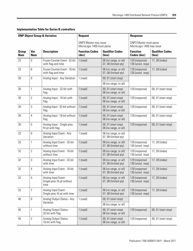
Micrologix 1400 Distributed Network Protocol (DNP3) 373
23 5 Frozen Counter Event - 32-bit with flag and time
1 (read) 06 (no range, or all)07, 08 (limited qty)
129 (response)130 (unsol. resp)
17, 28 (index)
23 6 Frozen Counter Event - 16-bit with flag and time
1 (read) 06 (no range, or all)07, 08 (limited qty)
129 (response)130 (unsol. resp)
17, 28 (index)
30 0 Analog Input - Any Variation 1 (read) 00, 01 (start-stop)
06 (no range, or all)
30 1 Analog Input - 32-bit with flag
1 (read) 00, 01 (start-stop)06 (no range, or all)
129 (response) 00, 01 (start-stop)
30 2 Analog Input - 16-bit with flag
1 (read) 00, 01 (start-stop)06 (no range, or all)
129 (response) 00, 01 (start-stop)
30 3 Analog Input - 32-bit without flag
1 (read) 00, 01 (start-stop)06 (no range, or all)
129 (response) 00, 01 (start-stop)
30 4 Analog Input - 16-bit without flag
1 (read) 00, 01 (start-stop)06 (no range, or all)
129 (response) 00, 01 (start-stop)
30 5 Analog Input - Single-prec flt-pt with flag
1 (read) 00, 01 (start-stop)06 (no range, or all)
129 (response) 00, 01 (start-stop)
32 0 Analog Input Event - Any Variation
1 (read) 06 (no range, or all)07, 08 (limited qty)
32 1 Analog Input Event - 32-bit without time
1 (read) 06 (no range, or all)07, 08 (limited qty)
129 (response)130 (unsol. resp)
17, 28 (index)
32 2 Analog Input Event - 16-bit without time
1 (read) 06 (no range, or all)07, 08 (limited qty)
129 (response)130 (unsol. resp)
17, 28 (index)
32 3 Analog Input Event - 32-bit with time
1 (read) 06 (no range, or all)07, 08 (limited qty)
129 (response)130 (unsol. resp)
17, 28 (index)
32 4 Analog Input Event - 16-bit with time
1 (read) 06 (no range, or all)07, 08 (limited qty)
129 (response)130 (unsol. resp)
17, 28 (index)
32 5 Analog Input Event - Single-prec flt-pt without time
1 (read) 06 (no range, or all)07, 08 (limited qty)
129 (response)130 (unsol. resp)
17, 28 (index)
32 7 Analog Input Event - Single-prec flt-pt with time
1 (read) 06 (no range, or all)07, 08 (limited qty)
129 (response)130 (unsol. resp)
17, 28 (index)
40 0 Analog Output Status - Any Variation
1 (read) 00, 01 (start-stop)
06 (no range, or all)
40 1 Analog Output Status - 32-bit with flag
1 (read) 00, 01 (start-stop)06 (no range, or all)
129 (response) 00, 01 (start-stop)
40 2 Analog Output Status - 16-bit with flag
1 (read) 00, 01 (start-stop)06 (no range, or all)
129 (response) 00, 01 (start-stop)
Implementation Table for Series B controllers
DNP Object Group & Variation Request
DNP3 Master may issueMicroLogix 1400 must parse
Response
DNP3 Master must parseMicroLogix 1400 may issue
Group Num
Var Num
Description Function Codes (dec)
Qualifier Codes (hex)
Function Codes (dec)
Qualifier Codes (hex)
Publication 1766-UM001F-EN-P - March 2011
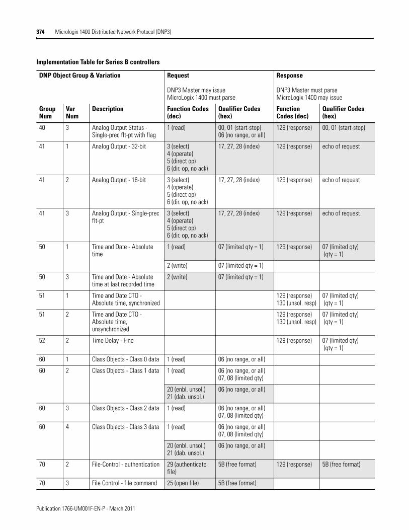
374 Micrologix 1400 Distributed Network Protocol (DNP3)
40 3 Analog Output Status - Single-prec flt-pt with flag
1 (read) 00, 01 (start-stop)06 (no range, or all)
129 (response) 00, 01 (start-stop)
41 1 Analog Output - 32-bit 3 (select)4 (operate)5 (direct op)6 (dir. op, no ack)
17, 27, 28 (index) 129 (response) echo of request
41 2 Analog Output - 16-bit 3 (select)4 (operate)5 (direct op)6 (dir. op, no ack)
17, 27, 28 (index) 129 (response) echo of request
41 3 Analog Output - Single-prec flt-pt
3 (select)4 (operate)5 (direct op)6 (dir. op, no ack)
17, 27, 28 (index) 129 (response) echo of request
50 1 Time and Date - Absolute time
1 (read) 07 (limited qty = 1) 129 (response) 07 (limited qty) (qty = 1)
2 (write) 07 (limited qty = 1)
50 3 Time and Date - Absolute time at last recorded time
2 (write) 07 (limited qty = 1)
51 1 Time and Date CTO - Absolute time, synchronized
129 (response)130 (unsol. resp)
07 (limited qty) (qty = 1)
51 2 Time and Date CTO - Absolute time, unsynchronized
129 (response)130 (unsol. resp)
07 (limited qty) (qty = 1)
52 2 Time Delay - Fine 129 (response) 07 (limited qty) (qty = 1)
60 1 Class Objects - Class 0 data 1 (read) 06 (no range, or all)
60 2 Class Objects - Class 1 data 1 (read) 06 (no range, or all)07, 08 (limited qty)
20 (enbl. unsol.)21 (dab. unsol.)
06 (no range, or all)
60 3 Class Objects - Class 2 data 1 (read) 06 (no range, or all)07, 08 (limited qty)
60 4 Class Objects - Class 3 data 1 (read) 06 (no range, or all)07, 08 (limited qty)
20 (enbl. unsol.)21 (dab. unsol.)
06 (no range, or all)
70 2 File-Control - authentication 29 (authenticate file)
5B (free format) 129 (response) 5B (free format)
70 3 File Control - file command 25 (open file) 5B (free format)
Implementation Table for Series B controllers
DNP Object Group & Variation Request
DNP3 Master may issueMicroLogix 1400 must parse
Response
DNP3 Master must parseMicroLogix 1400 may issue
Group Num
Var Num
Description Function Codes (dec)
Qualifier Codes (hex)
Function Codes (dec)
Qualifier Codes (hex)
Publication 1766-UM001F-EN-P - March 2011
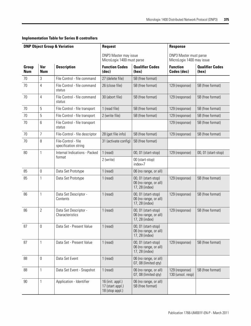
Micrologix 1400 Distributed Network Protocol (DNP3) 375
70 3 File Control - file command 27 (delete file) 5B (free format)
70 4 File Control - file command status
26 (close file) 5B (free format) 129 (response) 5B (free format)
70 4 File Control - file command status
30 (abort file) 5B (free format) 129 (response) 5B (free format)
70 5 File Control - file transport 1 (read file) 5B (free format) 129 (response) 5B (free format)
70 5 File Control - file transport 2 (write file) 5B (free format) 129 (response) 5B (free format)
70 6 File Control - file transport status
129 (response) 5B (free format)
70 7 File-Control - file descriptor 28 (get file info) 5B (free format) 129 (response) 5B (free format)
70 8 File-Control - file specification string
31 (activate config) 5B (free format)
80 1 Internal Indications - Packed format
1 (read) 00, 01 (start-stop) 129 (response) 00, 01 (start-stop)
2 (write) 00 (start-stop)index=7
85 0 Data Set Prototype 1 (read) 06 (no range, or all)
85 1 Data Set Prototype 1 (read) 00, 01 (start-stop)06 (no range, or all)17, 28 (index)
129 (response) 5B (free format)
86 1 Data Set Descriptor - Contents
1 (read) 00, 01 (start-stop)06 (no range, or all)17, 28 (index)
129 (response) 5B (free format)
86 2 Data Set Descriptor - Characteristics
1 (read) 00, 01 (start-stop)06 (no range, or all)17, 28 (index)
129 (response) 5B (free format)
87 0 Data Set - Present Value 1 (read) 00, 01 (start-stop)06 (no range, or all)17, 28 (index)
87 1 Data Set - Present Value 1 (read) 00, 01 (start-stop)06 (no range, or all)17, 28 (index)
129 (response) 5B (free format)
88 0 Data Set Event 1 (read) 06 (no range, or all)07, 08 (limited qty)
88 1 Data Set Event - Snapshot 1 (read) 06 (no range, or all)07, 08 (limited qty)
129 (response)130 (unsol. resp)
5B (free format)
90 1 Application - Identifier 16 (init. appl.)17 (start appl.)18 (stop appl.)
06 (no range, or all)5B (free format)
Implementation Table for Series B controllers
DNP Object Group & Variation Request
DNP3 Master may issueMicroLogix 1400 must parse
Response
DNP3 Master must parseMicroLogix 1400 may issue
Group Num
Var Num
Description Function Codes (dec)
Qualifier Codes (hex)
Function Codes (dec)
Qualifier Codes (hex)
Publication 1766-UM001F-EN-P - March 2011
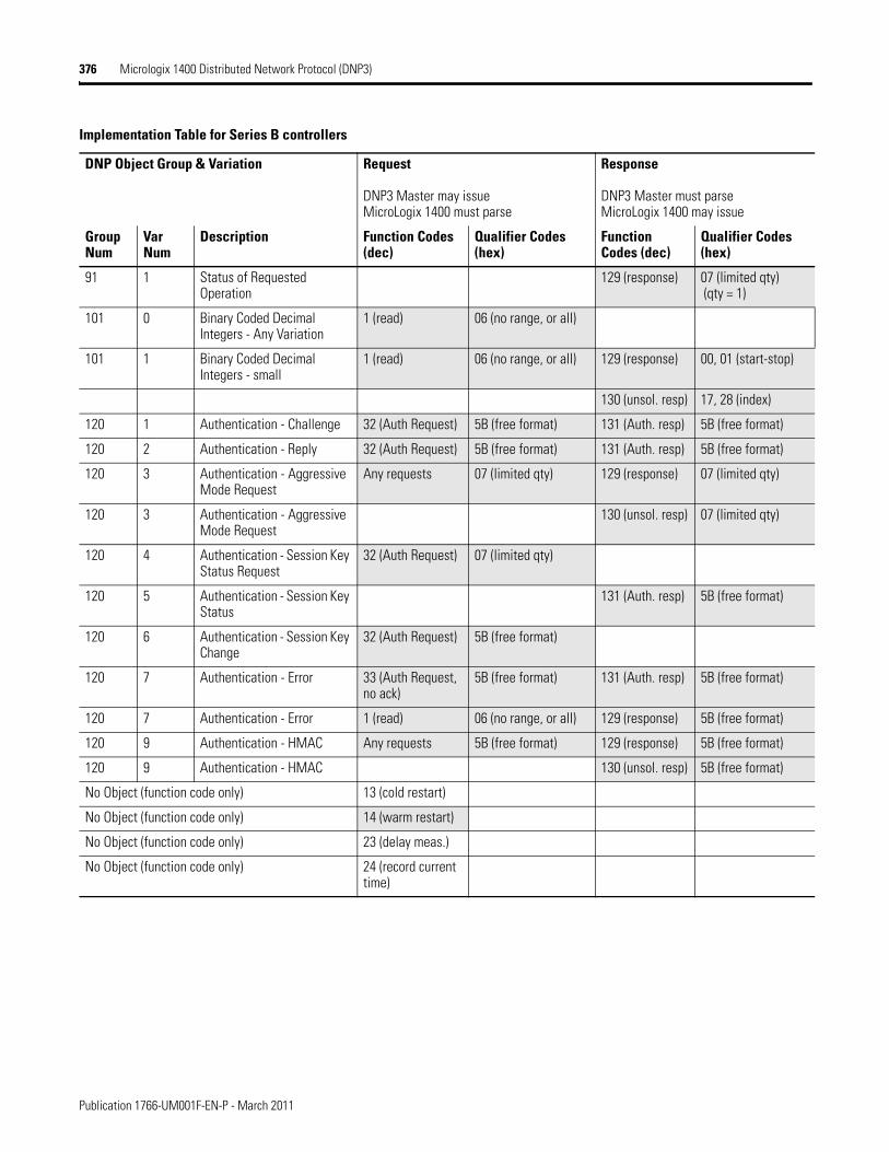
376 Micrologix 1400 Distributed Network Protocol (DNP3)
91 1 Status of Requested Operation
129 (response) 07 (limited qty) (qty = 1)
101 0 Binary Coded Decimal Integers - Any Variation
1 (read) 06 (no range, or all)
101 1 Binary Coded Decimal Integers - small
1 (read) 06 (no range, or all) 129 (response) 00, 01 (start-stop)
130 (unsol. resp) 17, 28 (index)
120 1 Authentication - Challenge 32 (Auth Request) 5B (free format) 131 (Auth. resp) 5B (free format)
120 2 Authentication - Reply 32 (Auth Request) 5B (free format) 131 (Auth. resp) 5B (free format)
120 3 Authentication - Aggressive Mode Request
Any requests 07 (limited qty) 129 (response) 07 (limited qty)
120 3 Authentication - Aggressive Mode Request
130 (unsol. resp) 07 (limited qty)
120 4 Authentication - Session Key Status Request
32 (Auth Request) 07 (limited qty)
120 5 Authentication - Session Key Status
131 (Auth. resp) 5B (free format)
120 6 Authentication - Session Key Change
32 (Auth Request) 5B (free format)
120 7 Authentication - Error 33 (Auth Request, no ack)
5B (free format) 131 (Auth. resp) 5B (free format)
120 7 Authentication - Error 1 (read) 06 (no range, or all) 129 (response) 5B (free format)
120 9 Authentication - HMAC Any requests 5B (free format) 129 (response) 5B (free format)
120 9 Authentication - HMAC 130 (unsol. resp) 5B (free format)
No Object (function code only) 13 (cold restart)
No Object (function code only) 14 (warm restart)
No Object (function code only) 23 (delay meas.)
No Object (function code only) 24 (record current time)
Implementation Table for Series B controllers
DNP Object Group & Variation Request
DNP3 Master may issueMicroLogix 1400 must parse
Response
DNP3 Master must parseMicroLogix 1400 may issue
Group Num
Var Num
Description Function Codes (dec)
Qualifier Codes (hex)
Function Codes (dec)
Qualifier Codes (hex)
Publication 1766-UM001F-EN-P - March 2011
Appendix G
Connecting to Networks via Ethernet Interface
This appendix:
· describes MicroLogix 1400 controllers and Ethernet communication.
· describes MicroLogix 1400 performance considerations.
· describes Ethernet network connections and media.
· explains how the MicroLogix 1400 establishes node connections.
· lists Ethernet configuration parameters and procedures.
· describes configuration for subnet masks and gateways.
MicroLogix 1400 Controllers and Ethernet Communication
Ethernet is a local area network that provides communication between various devices at 10 to 100 Mbps. The physical communication media options for the MicroLogix 1400 are:
· built-in
– twisted-pair (10/100Base-T)
· with media converters or hubs
– fiber optic
– broadband
– thick-wire coaxial cable (10Base-5)
– thin-wire coaxial cable (10Base-2)
See the following page for more information on Ethernet physical media.
377 Publication 1766-UM001F-EN-P - March 2011
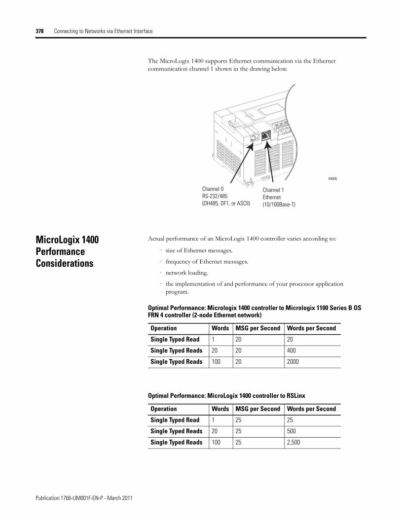
378 Connecting to Networks via Ethernet Interface
The MicroLogix 1400 supports Ethernet communication via the Ethernet communication channel 1 shown in the drawing below.
MicroLogix 1400 Performance Considerations
Actual performance of an MicroLogix 1400 controller varies according to:
· size of Ethernet messages.
· frequency of Ethernet messages.
· network loading.
· the implementation of and performance of your processor application program.
Channel 1 Ethernet (10/100Base-T)
Channel 0 RS-232/485 (DH485, DF1, or ASCII)
44606
Optimal Performance: Micrologix 1400 controller to Micrologix 1100 Series B OS FRN 4 controller (2-node Ethernet network)
Operation Words MSG per Second Words per Second
Single Typed Read 1 20 20
Single Typed Reads 20 20 400
Single Typed Reads 100 20 2000
Optimal Performance: MicroLogix 1400 controller to RSLinx
Operation Words MSG per Second Words per Second
Single Typed Read 1 25 25
Single Typed Reads 20 25 500
Single Typed Reads 100 25 2,500
Publication 1766-UM001F-EN-P - March 2011
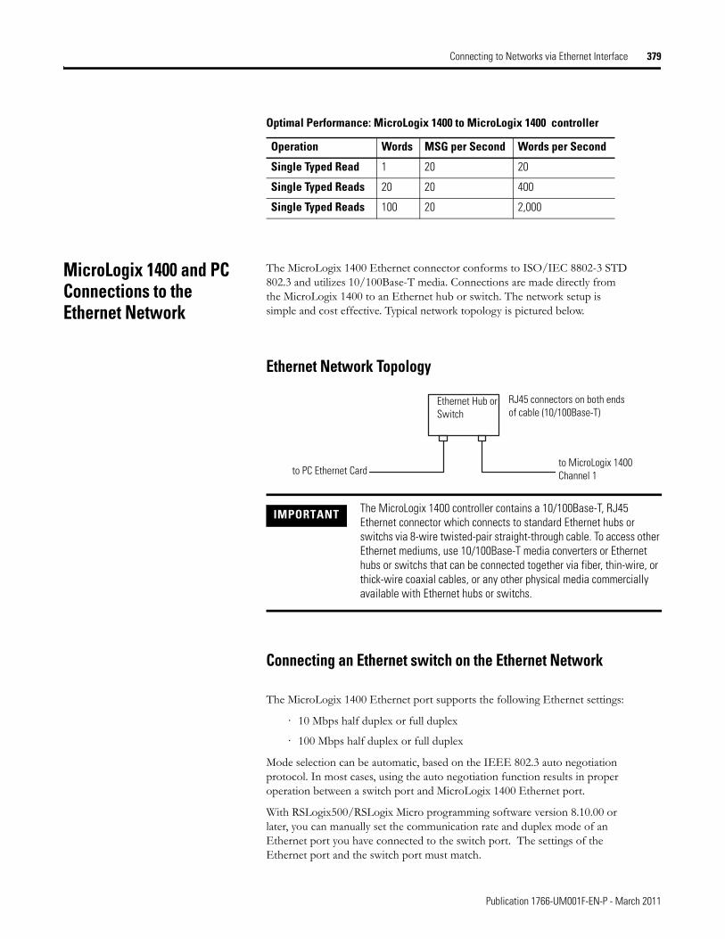
Connecting to Networks via Ethernet Interface 379
MicroLogix 1400 and PC Connections to the Ethernet Network
The MicroLogix 1400 Ethernet connector conforms to ISO/IEC 8802-3 STD 802.3 and utilizes 10/100Base-T media. Connections are made directly from the MicroLogix 1400 to an Ethernet hub or switch. The network setup is simple and cost effective. Typical network topology is pictured below.
Ethernet Network Topology
Connecting an Ethernet switch on the Ethernet Network
The MicroLogix 1400 Ethernet port supports the following Ethernet settings:
· 10 Mbps half duplex or full duplex
· 100 Mbps half duplex or full duplex
Mode selection can be automatic, based on the IEEE 802.3 auto negotiation protocol. In most cases, using the auto negotiation function results in proper operation between a switch port and MicroLogix 1400 Ethernet port.
With RSLogix500/RSLogix Micro programming software version 8.10.00 or later, you can manually set the communication rate and duplex mode of an Ethernet port you have connected to the switch port. The settings of the Ethernet port and the switch port must match.
Optimal Performance: MicroLogix 1400 to MicroLogix 1400 controller
Operation Words MSG per Second Words per Second
Single Typed Read 1 20 20
Single Typed Reads 20 20 400
Single Typed Reads 100 20 2,000
IMPORTANT The MicroLogix 1400 controller contains a 10/100Base-T, RJ45 Ethernet connector which connects to standard Ethernet hubs or switchs via 8-wire twisted-pair straight-through cable. To access other Ethernet mediums, use 10/100Base-T media converters or Ethernet hubs or switchs that can be connected together via fiber, thin-wire, or thick-wire coaxial cables, or any other physical media commercially available with Ethernet hubs or switchs.
to PC Ethernet Cardto MicroLogix 1400 Channel 1
RJ45 connectors on both ends of cable (10/100Base-T)
Ethernet Hub or Switch
Publication 1766-UM001F-EN-P - March 2011
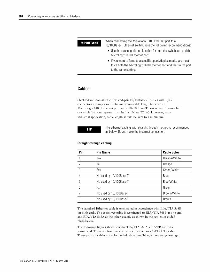
380 Connecting to Networks via Ethernet Interface
Cables
Shielded and non-shielded twisted-pair 10/100Base-T cables with RJ45 connectors are supported. The maximum cable length between an MicroLogix 1400 Ethernet port and a 10/100Base-T port on an Ethernet hub or switch (without repeaters or fiber) is 100 m (323 ft). However, in an industrial application, cable length should be kept to a minimum.
Straight-through cabling
The standard Ethernet cable is terminated in accordance with EIA/TIA 568B on both ends. The crossover cable is terminated to EIA/TIA 568B at one end and EIA/TIA 568A at the other, exactly as shown in the two color coded plugs below.
The following figures show how the TIA/EIA 568A and 568B are to be terminated. There are four pairs of wires contained in a CAT5 UTP cable. These pairs of cables are color coded white blue/blue, white orange/orange,
IMPORTANT When connecting the MicroLogix 1400 Ethernet port to a 10/100Base-T Ethernet switch, note the following recommendations:
• Use the auto negotiation function for both the switch port and the MicroLogix 1400 Ethernet port
• If you want to force to a specific speed/duplex mode, you must force both the MicroLogix 1400 Ethernet port and the switch port to the same setting.
TIP The Ethernet cabling with straight-through method is recommended as below. Do not make the incorrect connection.
Pin Pin Name Cable color
1 Tx+ Orange/White
2 Tx- Orange
3 Rx+ Green/White
4 No used by 10/100Base-T Blue
5 No used by 10/100Base-T Blue/White
6 Rx- Green
7 No used by 10/100Base-T Brown/White
8 No used by 10/100Base-T Brown
Publication 1766-UM001F-EN-P - March 2011
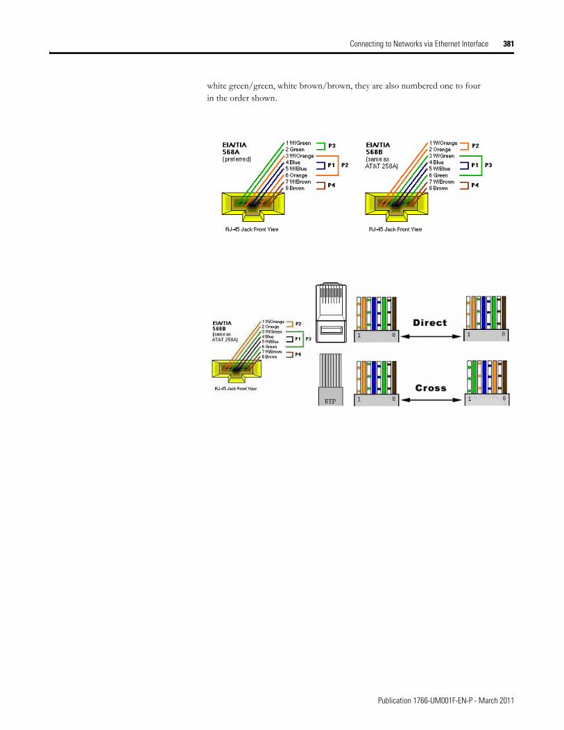
Connecting to Networks via Ethernet Interface 381
white green/green, white brown/brown, they are also numbered one to four in the order shown.
Publication 1766-UM001F-EN-P - March 2011
382 Connecting to Networks via Ethernet Interface
Ethernet Connections TCP/IP is the mechanism used to transport Ethernet messages. On top of TCP, Ethernet/IP and/or Modbus TCP protocol is required to establish sessions and to send the MSG commands. Connections can be initiated by either a client program (RSLinx application) or a processor.
The client program or processor must first establish a connection to the MicroLogix 1400 to enable the MicroLogix 1400 to receive solicited messages from a client program or another processor.
In order to send an outgoing message, the MicroLogix 1400 must first establish a connection with the destination node at a specified IP address on the Ethernet network. A connection is established when a MSG instruction executes and no previous connection exists.
When a MSG instruction executes, the MicroLogix 1400 checks to see whether a connection has been established with the destination node. If a connection has not been established, the MicroLogix 1400 attempts to establish a connection of the peer type.
In order to receive messages from another device on Ethernet, an “incoming” connection must be established. This incoming connection is made by the sending processor and uses one incoming connection in the receiving processor.
The MicroLogix 1400 supports a maximum of 32 EtherNet/IP connections and 32 Modbus TCP connections, allowing a maximum of 32 outgoing and a
TIP The most common wiring for RJ45 cables is the "straight through" cable which means that pin 1 of the plug on one end is connected to pin 1 of the plug on the other end. The straight through RJ45 cable is commonly used to connect network cards with hubs on 10Base-T and 100Base-Tx networks. On network cards, pair 1-2 is the transmitter, and pair 3-6 is the receiver. The other two pairs are not used. On hubs pair 1-2 is the receiver and 3-6 the transmitter. It may be best to wire your cables with the same color sequence. In this cable layout, all pins are wired one-to-one to the other side. The pins on the RJ45 connector are assigned in pairs, and every pair carries one differential signal. Each line pair has to be twisted.
In small networks where only two Ethernet devices need to be connected together point-to-point, a "cross over" RJ45 cable may be necessary, where the transmit and receive lines on both JR45 connectors are cross connected. The color coding for the cross over RJ45 cable have been defined in the EIA/TIA 568A standard. In a cross-over cable layout, you should remember that one end is normal, and the other end has the cross-over configuration.
However, because the MicroLogix 1400 Ethernet port implements "auto-crossover" (also called Automatic MDI/MDI-X Configuration), a straight through cable may be used even for direct point-to-point connections between the MicroLogix 1400 and another Ethernet device.
Publication 1766-UM001F-EN-P - March 2011
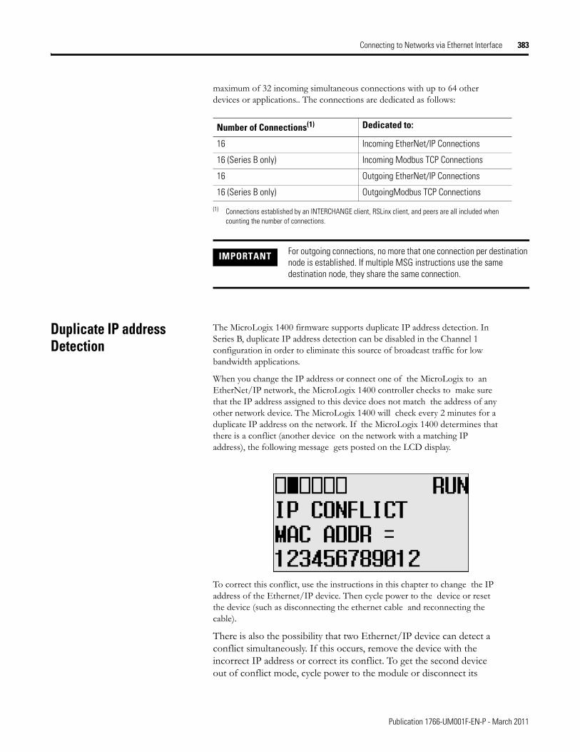
Connecting to Networks via Ethernet Interface 383
maximum of 32 incoming simultaneous connections with up to 64 other devices or applications.. The connections are dedicated as follows:
Duplicate IP address Detection
The MicroLogix 1400 firmware supports duplicate IP address detection. In Series B, duplicate IP address detection can be disabled in the Channel 1 configuration in order to eliminate this source of broadcast traffic for low bandwidth applications.
When you change the IP address or connect one of the MicroLogix to an EtherNet/IP network, the MicroLogix 1400 controller checks to make sure that the IP address assigned to this device does not match the address of any other network device. The MicroLogix 1400 will check every 2 minutes for a duplicate IP address on the network. If the MicroLogix 1400 determines that there is a conflict (another device on the network with a matching IP address), the following message gets posted on the LCD display.
To correct this conflict, use the instructions in this chapter to change the IP address of the Ethernet/IP device. Then cycle power to the device or reset the device (such as disconnecting the ethernet cable and reconnecting the cable).
There is also the possibility that two Ethernet/IP device can detect a conflict simultaneously. If this occurs, remove the device with the incorrect IP address or correct its conflict. To get the second device out of conflict mode, cycle power to the module or disconnect its
Number of Connections(1)
(1) Connections established by an INTERCHANGE client, RSLinx client, and peers are all included when counting the number of connections.
Dedicated to:
16 Incoming EtherNet/IP Connections
16 (Series B only) Incoming Modbus TCP Connections
16 Outgoing EtherNet/IP Connections
16 (Series B only) OutgoingModbus TCP Connections
IMPORTANT For outgoing connections, no more that one connection per destination node is established. If multiple MSG instructions use the same destination node, they share the same connection.
Publication 1766-UM001F-EN-P - March 2011
384 Connecting to Networks via Ethernet Interface
ethernet cable and reconnect the cable. The MicroLogix 1400 will check every 2 minutes for a duplicate IP address on the network.
Configuring the Ethernet Channel on the MicroLogix 1400
There are three ways to configure the MicroLogix 1400 Ethernet channel 1.
· via a BOOTP or DHCP request at controller powerup
· manually setting the configuration parameters using RSLogix 500/RSLogix Micro Programming Software
· via LCD display (see Configuring the Ethernet Port on page 143 and Configuring Ethernet Protocol Setup on page 146)
The configuration parameters are shown on the following page, and the configuration procedures follow.
Publication 1766-UM001F-EN-P - March 2011
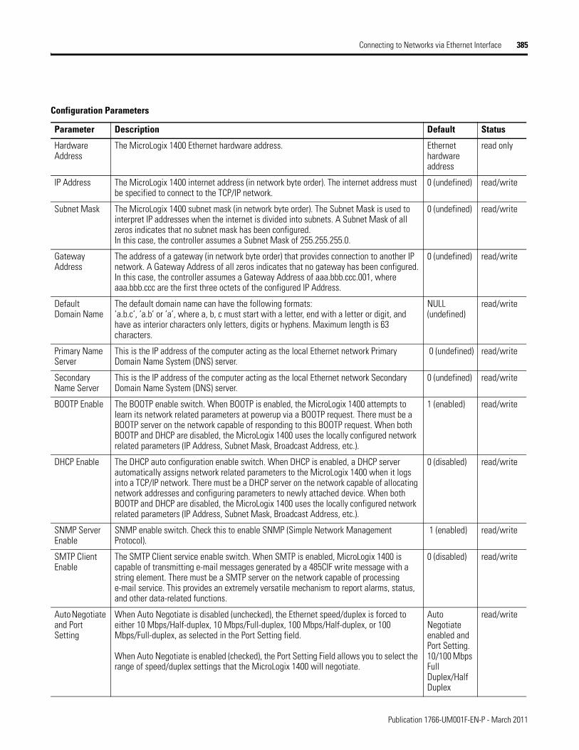
Connecting to Networks via Ethernet Interface 385
Configuration Parameters
Parameter Description Default Status
Hardware Address
The MicroLogix 1400 Ethernet hardware address. Ethernet hardware address
read only
IP Address The MicroLogix 1400 internet address (in network byte order). The internet address must be specified to connect to the TCP/IP network.
0 (undefined) read/write
Subnet Mask The MicroLogix 1400 subnet mask (in network byte order). The Subnet Mask is used to interpret IP addresses when the internet is divided into subnets. A Subnet Mask of all zeros indicates that no subnet mask has been configured.In this case, the controller assumes a Subnet Mask of 255.255.255.0.
0 (undefined) read/write
Gateway Address
The address of a gateway (in network byte order) that provides connection to another IP network. A Gateway Address of all zeros indicates that no gateway has been configured.In this case, the controller assumes a Gateway Address of aaa.bbb.ccc.001, where aaa.bbb.ccc are the first three octets of the configured IP Address.
0 (undefined) read/write
Default Domain Name
The default domain name can have the following formats:’a.b.c’, ’a.b’ or ’a’, where a, b, c must start with a letter, end with a letter or digit, and have as interior characters only letters, digits or hyphens. Maximum length is 63 characters.
NULL(undefined)
read/write
Primary Name Server
This is the IP address of the computer acting as the local Ethernet network Primary Domain Name System (DNS) server.
0 (undefined) read/write
Secondary Name Server
This is the IP address of the computer acting as the local Ethernet network Secondary Domain Name System (DNS) server.
0 (undefined) read/write
BOOTP Enable The BOOTP enable switch. When BOOTP is enabled, the MicroLogix 1400 attempts to learn its network related parameters at powerup via a BOOTP request. There must be a BOOTP server on the network capable of responding to this BOOTP request. When both BOOTP and DHCP are disabled, the MicroLogix 1400 uses the locally configured network related parameters (IP Address, Subnet Mask, Broadcast Address, etc.).
1 (enabled) read/write
DHCP Enable The DHCP auto configuration enable switch. When DHCP is enabled, a DHCP server automatically assigns network related parameters to the MicroLogix 1400 when it logs into a TCP/IP network. There must be a DHCP server on the network capable of allocating network addresses and configuring parameters to newly attached device. When both BOOTP and DHCP are disabled, the MicroLogix 1400 uses the locally configured network related parameters (IP Address, Subnet Mask, Broadcast Address, etc.).
0 (disabled) read/write
SNMP Server Enable
SNMP enable switch. Check this to enable SNMP (Simple Network Management Protocol).
1 (enabled) read/write
SMTP Client Enable
The SMTP Client service enable switch. When SMTP is enabled, MicroLogix 1400 is capable of transmitting e-mail messages generated by a 485CIF write message with a string element. There must be a SMTP server on the network capable of processing e-mail service. This provides an extremely versatile mechanism to report alarms, status, and other data-related functions.
0 (disabled) read/write
Auto Negotiate and Port Setting
When Auto Negotiate is disabled (unchecked), the Ethernet speed/duplex is forced to either 10 Mbps/Half-duplex, 10 Mbps/Full-duplex, 100 Mbps/Half-duplex, or 100 Mbps/Full-duplex, as selected in the Port Setting field.
When Auto Negotiate is enabled (checked), the Port Setting Field allows you to select the range of speed/duplex settings that the MicroLogix 1400 will negotiate.
Auto Negotiate enabled and Port Setting. 10/100 Mbps Full Duplex/Half Duplex
read/write
Publication 1766-UM001F-EN-P - March 2011
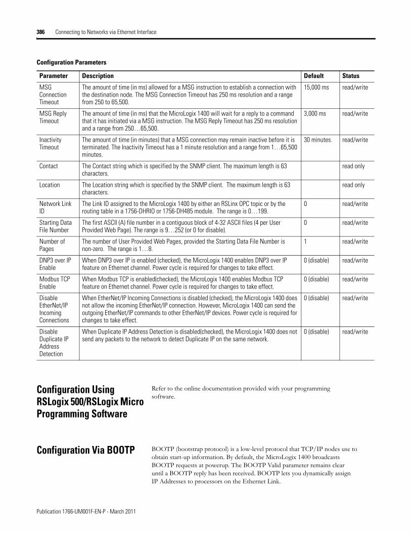
386 Connecting to Networks via Ethernet Interface
Configuration Using RSLogix 500/RSLogix Micro Programming Software
Refer to the online documentation provided with your programming software.
Configuration Via BOOTP BOOTP (bootstrap protocol) is a low-level protocol that TCP/IP nodes use to obtain start-up information. By default, the MicroLogix 1400 broadcasts BOOTP requests at powerup. The BOOTP Valid parameter remains clear until a BOOTP reply has been received. BOOTP lets you dynamically assign IP Addresses to processors on the Ethernet Link.
MSG Connection Timeout
The amount of time (in ms) allowed for a MSG instruction to establish a connection with the destination node. The MSG Connection Timeout has 250 ms resolution and a range from 250 to 65,500.
15,000 ms read/write
MSG Reply Timeout
The amount of time (in ms) that the MicroLogix 1400 will wait for a reply to a command that it has initiated via a MSG instruction. The MSG Reply Timeout has 250 ms resolution and a range from 250…65,500.
3,000 ms read/write
Inactivity Timeout
The amount of time (in minutes) that a MSG connection may remain inactive before it is terminated. The Inactivity Timeout has a 1 minute resolution and a range from 1…65,500 minutes.
30 minutes. read/write
Contact The Contact string which is specified by the SNMP client. The maximum length is 63 characters.
read only
Location The Location string which is specified by the SNMP client. The maximum length is 63 characters.
read only
Network Link ID
The Link ID assigned to the MicroLogix 1400 by either an RSLinx OPC topic or by the routing table in a 1756-DHRIO or 1756-DH485 module. The range is 0…199.
0 read/write
Starting Data File Number
The first ASCII (A) file number in a contiguous block of 4-32 ASCII files (4 per User Provided Web Page). The range is 9…252 (or 0 for disable).
0 read/write
Number of Pages
The number of User Provided Web Pages, provided the Starting Data File Number is non-zero. The range is 1…8.
1 read/write
DNP3 over IP Enable
When DNP3 over IP is enabled (checked), the MicroLogix 1400 enables DNP3 over IP feature on Ethernet channel. Power cycle is required for changes to take effect.
0 (disable) read/write
Modbus TCP Enable
When Modbus TCP is enabled(checked), the MicroLogix 1400 enables Modbus TCP feature on Ethernet channel. Power cycle is required for changes to take effect.
0 (disable) read/write
Disable EtherNet/IP Incoming Connections
When EtherNet/IP Incoming Connections is disabled (checked), the MicroLogix 1400 does not allow the incoming EtherNet/IP connection. However, MicroLogix 1400 can send the outgoing EtherNet/IP commands to other EtherNet/IP devices. Power cycle is required for changes to take effect.
0 (disable) read/write
Disable Duplicate IP Address Detection
When Duplicate IP Address Detection is disabled(checked), the MicroLogix 1400 does not send any packets to the network to detect Duplicate IP on the same network.
0 (disable) read/write
Configuration Parameters
Parameter Description Default Status
Publication 1766-UM001F-EN-P - March 2011
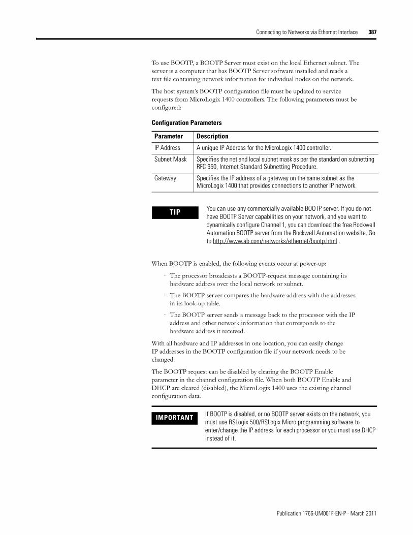
Connecting to Networks via Ethernet Interface 387
To use BOOTP, a BOOTP Server must exist on the local Ethernet subnet. The server is a computer that has BOOTP Server software installed and reads a text file containing network information for individual nodes on the network.
The host system’s BOOTP configuration file must be updated to service requests from MicroLogix 1400 controllers. The following parameters must be configured:
When BOOTP is enabled, the following events occur at power-up:
· The processor broadcasts a BOOTP-request message containing its hardware address over the local network or subnet.
· The BOOTP server compares the hardware address with the addresses in its look-up table.
· The BOOTP server sends a message back to the processor with the IP address and other network information that corresponds to the hardware address it received.
With all hardware and IP addresses in one location, you can easily change IP addresses in the BOOTP configuration file if your network needs to be changed.
The BOOTP request can be disabled by clearing the BOOTP Enable parameter in the channel configuration file. When both BOOTP Enable and DHCP are cleared (disabled), the MicroLogix 1400 uses the existing channel configuration data.
Configuration Parameters
Parameter Description
IP Address A unique IP Address for the MicroLogix 1400 controller.
Subnet Mask Specifies the net and local subnet mask as per the standard on subnetting RFC 950, Internet Standard Subnetting Procedure.
Gateway Specifies the IP address of a gateway on the same subnet as the MicroLogix 1400 that provides connections to another IP network.
TIP You can use any commercially available BOOTP server. If you do not have BOOTP Server capabilities on your network, and you want to dynamically configure Channel 1, you can download the free Rockwell Automation BOOTP server from the Rockwell Automation website. Go to http://www.ab.com/networks/ethernet/bootp.html .
IMPORTANT If BOOTP is disabled, or no BOOTP server exists on the network, you must use RSLogix 500/RSLogix Micro programming software to enter/change the IP address for each processor or you must use DHCP instead of it.
Publication 1766-UM001F-EN-P - March 2011
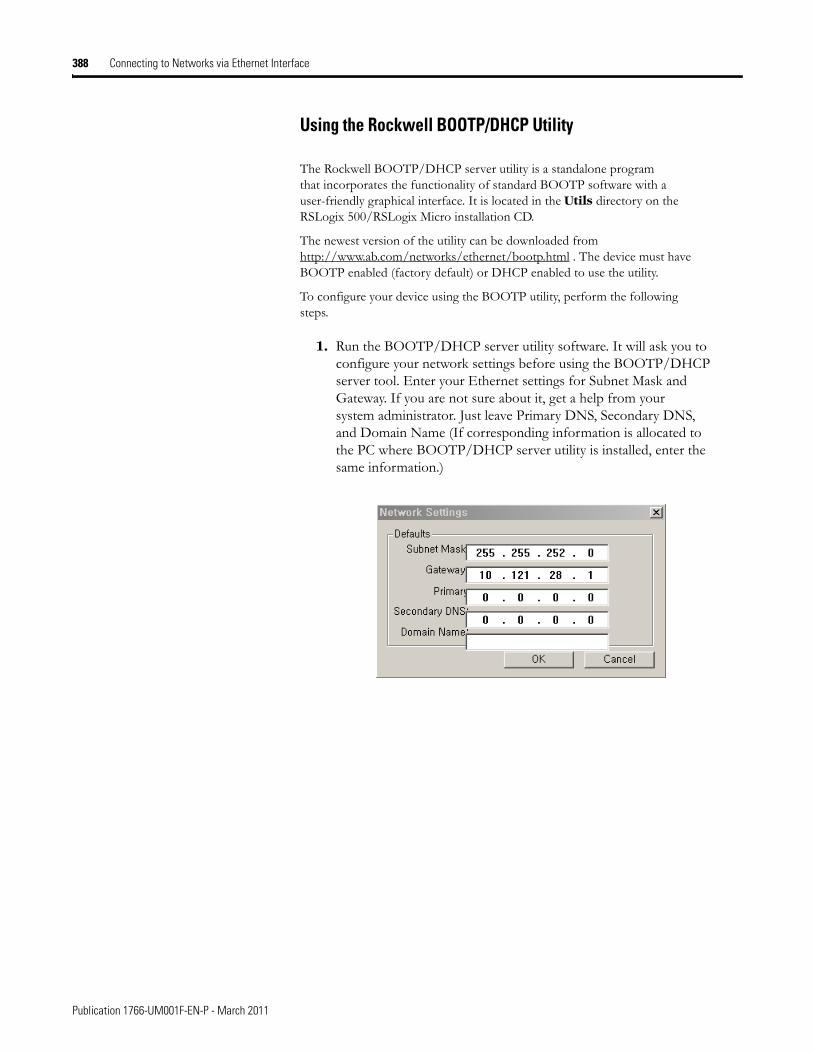
388 Connecting to Networks via Ethernet Interface
Using the Rockwell BOOTP/DHCP Utility
The Rockwell BOOTP/DHCP server utility is a standalone program that incorporates the functionality of standard BOOTP software with a user-friendly graphical interface. It is located in the Utils directory on the RSLogix 500/RSLogix Micro installation CD.
The newest version of the utility can be downloaded from http://www.ab.com/networks/ethernet/bootp.html . The device must have BOOTP enabled (factory default) or DHCP enabled to use the utility.
To configure your device using the BOOTP utility, perform the following steps.
1. Run the BOOTP/DHCP server utility software. It will ask you to configure your network settings before using the BOOTP/DHCP server tool. Enter your Ethernet settings for Subnet Mask and Gateway. If you are not sure about it, get a help from your system administrator. Just leave Primary DNS, Secondary DNS, and Domain Name (If corresponding information is allocated to the PC where BOOTP/DHCP server utility is installed, enter the same information.)
Publication 1766-UM001F-EN-P - March 2011
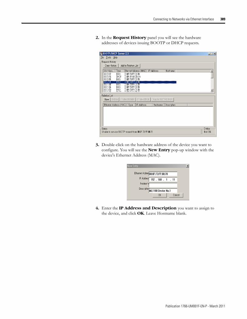
Connecting to Networks via Ethernet Interface 389
2. In the Request History panel you will see the hardware addresses of devices issuing BOOTP or DHCP requests.
3. Double-click on the hardware address of the device you want to configure. You will see the New Entry pop-up window with the device's Ethernet Address (MAC).
4. Enter the IP Address and Description you want to assign to the device, and click OK. Leave Hostname blank.
Publication 1766-UM001F-EN-P - March 2011
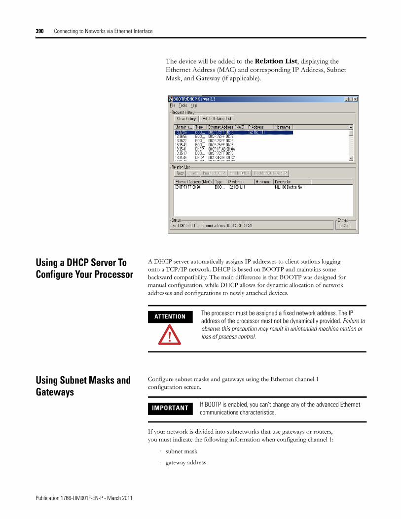
390 Connecting to Networks via Ethernet Interface
The device will be added to the Relation List, displaying the Ethernet Address (MAC) and corresponding IP Address, Subnet Mask, and Gateway (if applicable).
Using a DHCP Server To Configure Your Processor
A DHCP server automatically assigns IP addresses to client stations logging onto a TCP/IP network. DHCP is based on BOOTP and maintains some backward compatibility. The main difference is that BOOTP was designed for manual configuration, while DHCP allows for dynamic allocation of network addresses and configurations to newly attached devices.
Using Subnet Masks and Gateways
Configure subnet masks and gateways using the Ethernet channel 1 configuration screen.
If your network is divided into subnetworks that use gateways or routers, you must indicate the following information when configuring channel 1:
· subnet mask
· gateway address
ATTENTION The processor must be assigned a fixed network address. The IP address of the processor must not be dynamically provided. Failure to observe this precaution may result in unintended machine motion or loss of process control.
IMPORTANT If BOOTP is enabled, you can’t change any of the advanced Ethernet communications characteristics.
Publication 1766-UM001F-EN-P - March 2011
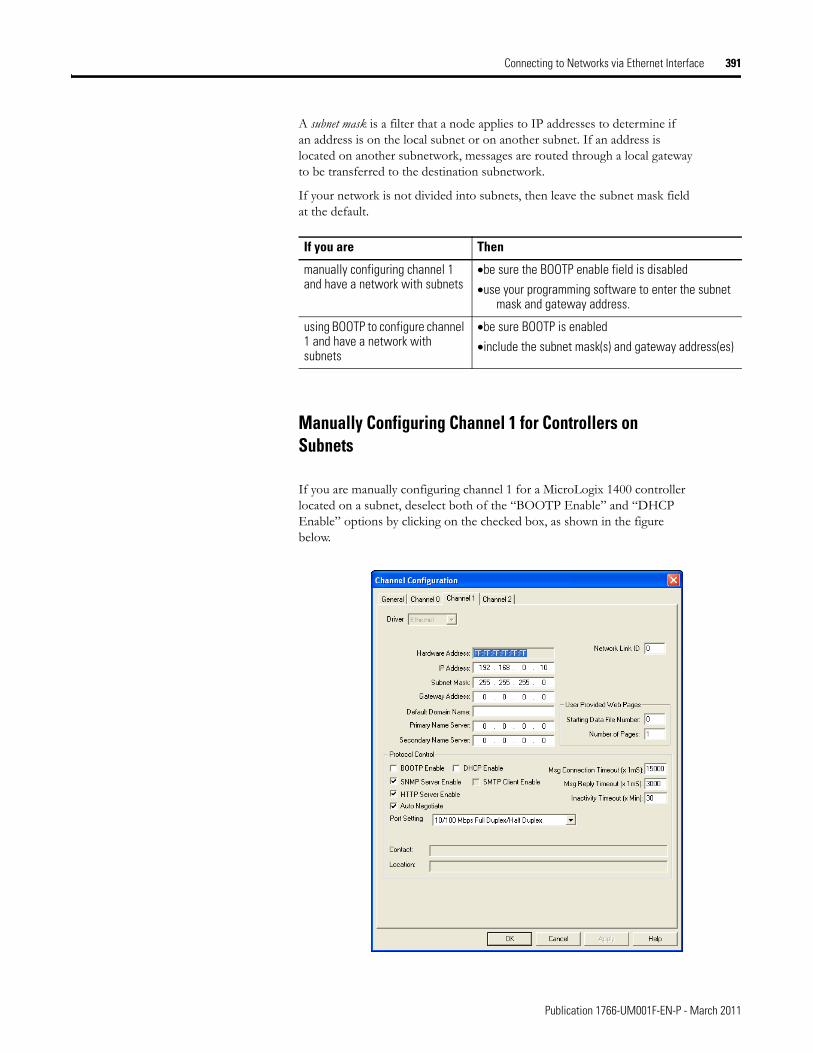
Connecting to Networks via Ethernet Interface 391
A subnet mask is a filter that a node applies to IP addresses to determine if an address is on the local subnet or on another subnet. If an address is located on another subnetwork, messages are routed through a local gateway to be transferred to the destination subnetwork.
If your network is not divided into subnets, then leave the subnet mask field at the default.
Manually Configuring Channel 1 for Controllers on Subnets
If you are manually configuring channel 1 for a MicroLogix 1400 controller located on a subnet, deselect both of the “BOOTP Enable” and “DHCP Enable” options by clicking on the checked box, as shown in the figure below.
If you are Then
manually configuring channel 1 and have a network with subnets
•be sure the BOOTP enable field is disabled
•use your programming software to enter the subnet mask and gateway address.
using BOOTP to configure channel 1 and have a network with subnets
•be sure BOOTP is enabled
•include the subnet mask(s) and gateway address(es)
Publication 1766-UM001F-EN-P - March 2011
392 Connecting to Networks via Ethernet Interface
See the table below to configure the subnet mask and gateway address fields for each controller via your programming software.
MicroLogix 1400 Embedded Web Server Capability
MicroLogix 1400 controllers include not only the embedded web server which allows viewing of module information, TCP/IP configuration, and diagnostic information, but the capabilities that also allow viewing of the data file via Ethernet using a standard web browser.
For more information on MicroLogix 1400 embedded web server capability, refer to the MicroLogix 1400 Embedded Web Server User Manual, publication 1766-UM002.
This field: Specifies: Configure by doing the following:
Subnet Mask The controller’s subnet mask.
The subnet mask is used to interpret IP addresses when the internet is divided into subnets.
Enter an address of the following form:
a.b.c.d Where: a, b, c, d are between 0...255 (decimal)
If your network is not divided into subnets, then leave the subnet mask field at the default. If you change the default and need to reset it, type 0.0.0.0.
Gateway Address The IP address of the gateway that provides a connection to another IP network.
This field is required when you communicate with other devices not on a local subnet.
Enter an address of the following form:
a.b.c.d Where: a, b, c, d are between 0...255 (decimal)
The default address is No Gateway.
Publication 1766-UM001F-EN-P - March 2011

Connecting to Networks via Ethernet Interface 393
Notes:
Publication 1766-UM001F-EN-P - March 2011

394 Connecting to Networks via Ethernet Interface
Publication 1766-UM001F-EN-P - March 2011
Appendix H
System Loading and Heat Dissipation
System Loading Calculations
The MicroLogix 1400 controller is designed to support up to any seven 1762 expansion I/O modules.
When you connect MicroLogix accessories and expansion I/O, an electrical load is placed on the controller power supply. This section shows how to calculate the load of your control system.
The following example is provided to illustrate system loading calculation. The system calculation procedure accounts for the amount of 5V DC and 24V DC current consumed by controller, expansion I/O, and user-supplied equipment. Use the System Loading Worksheet on page 397 to calculate your controller configuration.
TIPat
A maximum of seven 1762 I/O modules, in any combination, can be connected to a MicroLogix 1400 controller. You can use this appendix to determine the power supply load and heat dissipation for your system.
395 Publication 1766-UM001F-EN-P - March 2011
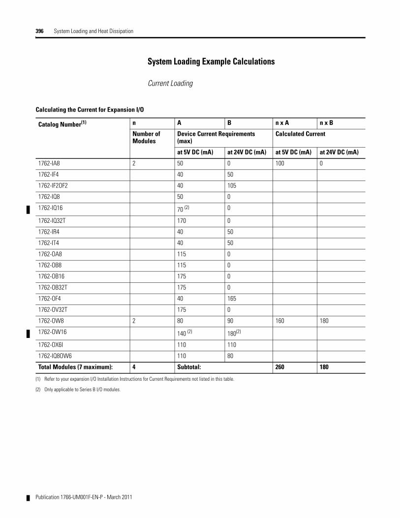
396 System Loading and Heat Dissipation
System Loading Example Calculations
Current Loading
Calculating the Current for Expansion I/O
Catalog Number(1) n A B n x A n x B
Number of Modules
Device Current Requirements (max)
Calculated Current
at 5V DC (mA) at 24V DC (mA) at 5V DC (mA) at 24V DC (mA)
1762-IA8 2 50 0 100 0
1762-IF4 40 50
1762-IF2OF2 40 105
1762-IQ8 50 0
1762-IQ16 70 (2) 0
1762-IQ32T 170 0
1762-IR4 40 50
1762-IT4 40 50
1762-OA8 115 0
1762-OB8 115 0
1762-OB16 175 0
1762-OB32T 175 0
1762-OF4 40 165
1762-OV32T 175 0
1762-OW8 2 80 90 160 180
1762-OW16 140 (2) 180(2)
1762-OX6I 110 110
1762-IQ8OW6 110 80
Total Modules (7 maximum): 4 Subtotal: 260 180
(1) Refer to your expansion I/O Installation Instructions for Current Requirements not listed in this table.
(2) Only applicable to Series B I/O modules.
Publication 1766-UM001F-EN-P - March 2011
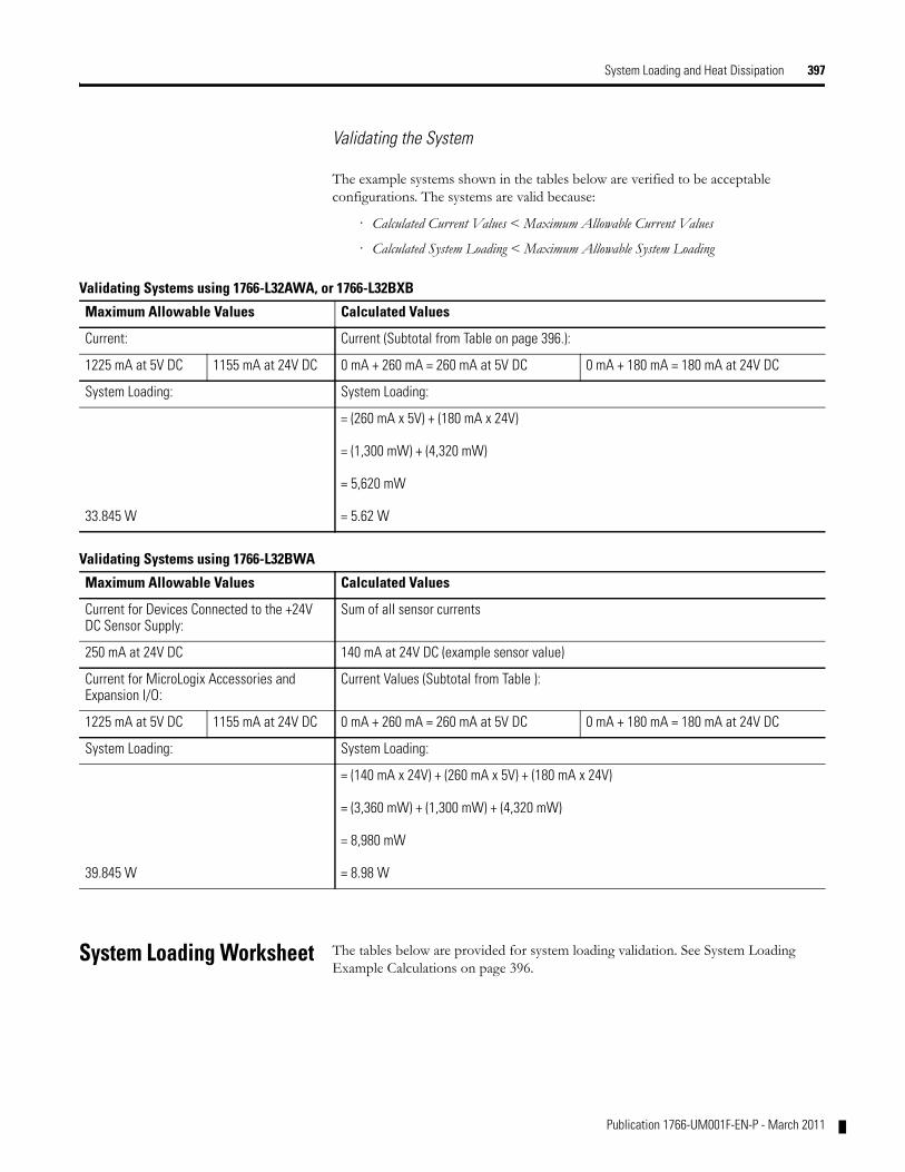
System Loading and Heat Dissipation 397
Validating the System
The example systems shown in the tables below are verified to be acceptable configurations. The systems are valid because:
· Calculated Current Values < Maximum Allowable Current Values
· Calculated System Loading < Maximum Allowable System Loading
System Loading Worksheet The tables below are provided for system loading validation. See System Loading Example Calculations on page 396.
Validating Systems using 1766-L32AWA, or 1766-L32BXB
Maximum Allowable Values Calculated Values
Current: Current (Subtotal from Table on page 396.):
1225 mA at 5V DC 1155 mA at 24V DC 0 mA + 260 mA = 260 mA at 5V DC 0 mA + 180 mA = 180 mA at 24V DC
System Loading: System Loading:
33.845 W
= (260 mA x 5V) + (180 mA x 24V)
= (1,300 mW) + (4,320 mW)
= 5,620 mW
= 5.62 W
Validating Systems using 1766-L32BWA
Maximum Allowable Values Calculated Values
Current for Devices Connected to the +24V DC Sensor Supply:
Sum of all sensor currents
250 mA at 24V DC 140 mA at 24V DC (example sensor value)
Current for MicroLogix Accessories and Expansion I/O:
Current Values (Subtotal from Table ):
1225 mA at 5V DC 1155 mA at 24V DC 0 mA + 260 mA = 260 mA at 5V DC 0 mA + 180 mA = 180 mA at 24V DC
System Loading: System Loading:
39.845 W
= (140 mA x 24V) + (260 mA x 5V) + (180 mA x 24V)
= (3,360 mW) + (1,300 mW) + (4,320 mW)
= 8,980 mW
= 8.98 W
Publication 1766-UM001F-EN-P - March 2011
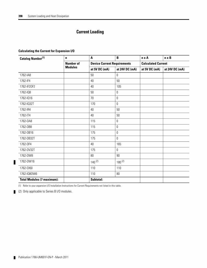
398 System Loading and Heat Dissipation
Current Loading
Calculating the Current for Expansion I/O
Catalog Number(1) n A B n x A n x B
Number of Modules
Device Current Requirements Calculated Current
at 5V DC (mA) at 24V DC (mA) at 5V DC (mA) at 24V DC (mA)
1762-IA8 50 0
1762-IF4 40 50
1762-IF2OF2 40 105
1762-IQ8 50 0
1762-IQ16 70 0
1762-IQ32T 170 0
1762-IR4 40 50
1762-IT4 40 50
1762-OA8 115 0
1762-OB8 115 0
1762-OB16 175 0
1762-OB32T 175 0
1762-OF4 40 165
1762-OV32T 175 0
1762-OW8 80 90
1762-OW16 140 (2) 180 (2)
1762-OX6I 110 110
1762-IQ8OW6 110 80
Total Modules (7 maximum): Subtotal:
(1) Refer to your expansion I/O Installation Instructions for Current Requirements not listed in this table.
(2) Only applicable to Series B I/O modules.
Publication 1766-UM001F-EN-P - March 2011
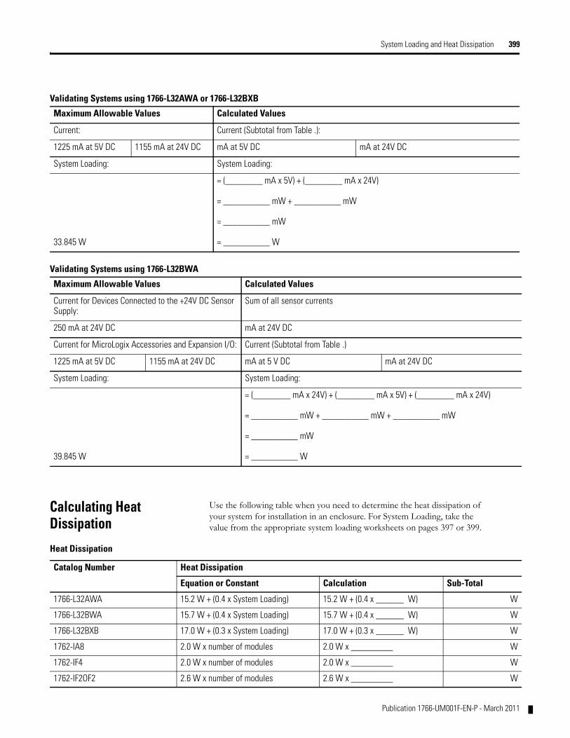
System Loading and Heat Dissipation 399
Calculating Heat Dissipation
Use the following table when you need to determine the heat dissipation of your system for installation in an enclosure. For System Loading, take the value from the appropriate system loading worksheets on pages 397 or 399.
Validating Systems using 1766-L32AWA or 1766-L32BXB
Maximum Allowable Values Calculated Values
Current: Current (Subtotal from Table .):
1225 mA at 5V DC 1155 mA at 24V DC mA at 5V DC mA at 24V DC
System Loading: System Loading:
33.845 W
= (________ mA x 5V) + (________ mA x 24V)
= __________ mW + __________ mW
= __________ mW
= __________ W
Validating Systems using 1766-L32BWA
Maximum Allowable Values Calculated Values
Current for Devices Connected to the +24V DC Sensor Supply:
Sum of all sensor currents
250 mA at 24V DC mA at 24V DC
Current for MicroLogix Accessories and Expansion I/O: Current (Subtotal from Table .)
1225 mA at 5V DC 1155 mA at 24V DC mA at 5 V DC mA at 24V DC
System Loading: System Loading:
39.845 W
= (________ mA x 24V) + (________ mA x 5V) + (________ mA x 24V)
= __________ mW + __________ mW + __________ mW
= __________ mW
= __________ W
Heat Dissipation
Catalog Number Heat Dissipation
Equation or Constant Calculation Sub-Total
1766-L32AWA 15.2 W + (0.4 x System Loading) 15.2 W + (0.4 x ______ W) W
1766-L32BWA 15.7 W + (0.4 x System Loading) 15.7 W + (0.4 x ______ W) W
1766-L32BXB 17.0 W + (0.3 x System Loading) 17.0 W + (0.3 x ______ W) W
1762-IA8 2.0 W x number of modules 2.0 W x _________ W
1762-IF4 2.0 W x number of modules 2.0 W x _________ W
1762-IF2OF2 2.6 W x number of modules 2.6 W x _________ W
Publication 1766-UM001F-EN-P - March 2011
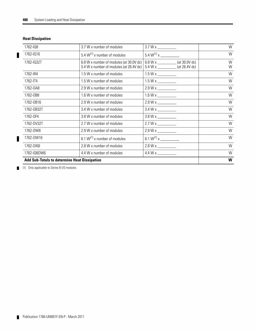
400 System Loading and Heat Dissipation
1762-IQ8 3.7 W x number of modules 3.7 W x _________ W
1762-IQ16 5.4 W(1) x number of modules 5.4 W(1) x _________ W
1762-IQ32T 6.8 W x number of modules (at 30.0V dc)5.4 W x number of modules (at 26.4V dc)
6.8 W x _________ (at 30.0V dc)5.4 W x _________ (at 26.4V dc)
WW
1762-IR4 1.5 W x number of modules 1.5 W x _________ W
1762-IT4 1.5 W x number of modules 1.5 W x _________ W
1762-OA8 2.9 W x number of modules 2.9 W x _________ W
1762-OB8 1.6 W x number of modules 1.6 W x _________ W
1762-OB16 2.9 W x number of modules 2.9 W x _________ W
1762-OB32T 3.4 W x number of modules 3.4 W x _________ W
1762-OF4 3.8 W x number of modules 3.8 W x _________ W
1762-OV32T 2.7 W x number of modules 2.7 W x _________ W
1762-OW8 2.9 W x number of modules 2.9 W x _________ W
1762-OW16 6.1 W(1) x number of modules 6.1 W(1) x _________ W
1762-OX6I 2.8 W x number of modules 2.8 W x _________ W
1762-IQ8OW6 4.4 W x number of modules 4.4 W x _________ W
Add Sub-Totals to determine Heat Dissipation W
(1) Only applicable to Series B I/O modules.
Heat Dissipation
Publication 1766-UM001F-EN-P - March 2011
Glossary
The following terms are used throughout this manual. Refer to the Allen-Bradley Industrial Automation Glossary, publication AG-7.1, for a complete guide to Allen-Bradley technical terms.
address
A character string that uniquely identifies a memory location. For example, I:1/0 is the memory address for the data located in the Input file location word1, bit 0.
AIC+ Advanced Interface Converter
A device that provides a communication link between various networked devices. (Catalog Number 1761-NET-AIC.)
application
1) A machine or process monitored and controlled by a controller. 2) The use of computer- or processor-based routines for specific purposes.
baud rate
The speed of communication between devices. All devices must communicate at the same baud rate on a network.
bit
The smallest storage location in memory that contains either a 1 (ON) or a 0 (OFF).
block diagrams
A schematic drawing.
Boolean operators
Logical operators such as AND, OR, NAND, NOR, NOT, and Exclusive-OR that can be used singularly or in combination to form logic statements or circuits. Can have an output response of T or F.
branch
A parallel logic path within a rung of a ladder program.
communication scan
A part of the controller’s operating cycle. Communication with other devices, such as software running on a personal computer, takes place.
controller
A device, such as a programmable controller, used to monitor input devices and control output devices.
controller overhead
An internal portion of the operating cycle used for housekeeping and set-up purposes.
401 Publication 1766-UM001F-EN-P - March 2011
402
control profile
The means by which a controller determines which outputs turn on under what conditions.
counter
1) An electro-mechanical relay-type device that counts the occurrence of some event. May be pulses developed from operations such as switch closures or interruptions of light beams. 2) In controllers, a software counter eliminates the need for hardware counters. The software counter can be given a preset count value to count up or down whenever the counted event occurs.
CPU (Central Processing Unit)
The decision-making and data storage section of a programmable controller.
data table
The part of processor memory that contains I/O values and files where data is monitored, manipulated, and changed for control purposes.
DIN rail
Manufactured according to Deutsche Industrie Normenausshus (DIN) standards, a metal railing designed to ease installation and mounting of your controller.
download
Data is transferred from a programming or storage device to another device.
DTE (Data Terminal Equipment)
Equipment that is attached to a network to send or receive data, or both.
embedded I/O
Embedded I/O is the controller’s on-board I/O.
EMI
Electromagnetic interference.
encoder
1) A rotary device that transmits position information. 2) A device that transmits a fixed number of pulses for each revolution.
executing mode
Any run or test mode.
expansion I/O
Expansion I/O is I/O that is connected to the controller via a bus or cable. MicroLogix 1400 controllers use Bulletin 1762 expansion I/O.
Publication 1766-UM001F-EN-P - March 2011
403
false
The status of an instruction that does not provide a continuous logical path on a ladder rung.
FIFO (First-In-First-Out)
The order that data is entered into and retrieved from a file.
file
A collection of information organized into one group.
full-duplex
A bidirectional mode of communication where data may be transmitted and received simultaneously (contrast with half-duplex).
half-duplex
A communication link in which data transmission is limited to one direction at a time.
hard disk
A storage area in a personal computer that may be used to save processor files and reports for future use.
high byte
Bits 8 to 15 of a word.
input device
A device, such as a push button or a switch, that supplies signals to the input circuits of the controller.
inrush current
The temporary surge current produced when a device or circuit is initially energized.
instruction
A mnemonic and data address defining an operation to be performed by the processor. A rung in a program consists of a set of input and output instructions. The input instructions are evaluated by the controller as being true or false. In turn, the controller sets the output instructions to true or false.
instruction set
The set of general purpose instructions available with a given controller.
I/O (Inputs and Outputs)
Consists of input and output devices that provide and/or receive data from the controller.
Publication 1766-UM001F-EN-P - March 2011
404
jump
Change in normal sequence of program execution, by executing an instruction that alters the program counter (sometimes called a branch). In ladder programs a JUMP (JMP) instruction causes execution to jump to a labeled rung.
ladder logic
A program written in a format resembling a ladder-like diagram. The program is used by a programmable controller to control devices.
least significant bit (LSB)
The digit (or bit) in a binary word (code) that carries the smallest value of weight.
LED (Light Emitting Diode)
Used as status indicator for processor functions and inputs and outputs.
LIFO (Last-In-First-Out)
The order that data is entered into and retrieved from a file.
low byte
Bits 0 to 7 of a word.
logic
A process of solving complex problems through the repeated use of simple functions that can be either true or false. General term for digital circuits and programmed instructions to perform required decision making and computational functions.
Master Control Relay (MCR)
A mandatory hard-wired relay that can be de-energized by any series-connected emergency stop switch. Whenever the MCR is de-energized, its contacts open to de-energize all application I/O devices.
mnemonic
A simple and easy to remember term that is used to represent a complex or lengthy set of information.
modem
Modulator/demodulator. Equipment that connects data terminal equipment to a communication line.
modes
Selected methods of operation. Example: run, test, or program.
Publication 1766-UM001F-EN-P - March 2011
405
negative logic
The use of binary logic in such a way that “0” represents the voltage level normally associated with logic 1 (for example, 0 = +5V, 1 = 0V). Positive is more conventional (for example, 1 = +5V, 0 = 0V).
network
A series of stations (nodes) connected by some type of communication medium. A network may be made up of a single link or multiple links.
nominal input current
The current at nominal input voltage.
normally closed
Contacts on a relay or switch that are closed when the relay is de-energized or the switch is deactivated; they are open when the relay is energized or the switch is activated. In ladder programming, a symbol that allows logic continuity (flow) if the referenced input is logic “0” when evaluated.
normally open
Contacts on a relay or switch that are open when the relay is de-energized or the switch is deactivated. (They are closed when the relay is energized or the switch is activated.) In ladder programming, a symbol that allows logic continuity (flow) if the referenced input is logic “1” when evaluated.
off-delay time
The OFF delay time is a measure of the time required for the controller logic to recognize that a signal has been removed from the input terminal of the controller. The time is determined by circuit component delays and by any filter adjustment applied.
offline
Describes devices not under direct communication.
offset
The steady-state deviation of a controlled variable from a fixed point.
off-state leakage current
When an ideal mechanical switch is opened (off-state) no current flows through the switch. Practical semiconductor switches, and the transient suppression components which are sometimes used to protect switches, allow a small current to flow when the switch is in the off state. This current is referred to as the off-state leakage current. To ensure reliable operation, the off-state leakage current rating of a switch should be less than the minimum operating current rating of the load that is connected to the switch.
Publication 1766-UM001F-EN-P - March 2011
406
on-delay time
The ON delay time is a measure of the time required for the controller logic to recognize that a signal has been presented at the input terminal of the controller.
one-shot
A programming technique that sets a bit for only one program scan.
online
Describes devices under direct communication. For example, when RSLogix 500/RSLogix Micro is monitoring the program file in a controller.
operating voltage
For inputs, the voltage range needed for the input to be in the On state. For outputs, the allowable range of user-supplied voltage.
output device
A device, such as a pilot light or a motor starter coil, that is controlled by the controller.
processor
A Central Processing Unit. (See CPU.)
processor file
The set of program and data files used by the controller to control output devices. Only one processor file may be stored in the controller at a time.
program file
The area within a processor file that contains the ladder logic program.
program mode
When the controller is not executing the processor file and all outputs are de-energized.
program scan
A part of the controller’s operating cycle. During the scan the ladder program is executed and the output data file is updated based on the program and the input data file.
programming device
Executable programming package used to develop ladder diagrams.
protocol
The packaging of information that is transmitted across a network.
Publication 1766-UM001F-EN-P - March 2011
407
read
To acquire data from a storage place. For example, the processor READs information from the input data file to solve the ladder program.
relay
An electrically operated device that mechanically switches electrical circuits.
relay logic
A representation of the program or other logic in a form normally used for relays.
restore
To download (transfer) a program from a personal computer to a controller.
reserved bit
A status file location that the user should not read or write to.
retentive data
Information associated with data files (timers, counters, inputs, and outputs) in a program that is preserved through power cycles.
RS-232
An EIA standard that specifies electrical, mechanical, and functional characteristics for serial binary communication circuits. A single-ended serial communication interface.
run mode
This is an executing mode during which the controller scans or executes the ladder program, monitors input devices, energizes output devices, and acts on enabled I/O forces.
rung
Ladder logic is comprised of a set of rungs. A rung contains input and output instructions. During Run mode, the inputs on a rung are evaluated to be true or false. If a path of true logic exists, the outputs are made true. If all paths are false, the outputs are made false.
save
To upload (transfer) a program stored in memory from a controller to a personal computer; OR to save a program to a computer hard disk.
scan time
The time required for the controller to execute the instructions in the program. The scan time may vary depending on the instructions and each instruction’s status during the scan.
Publication 1766-UM001F-EN-P - March 2011
408
sinking
A term used to describe current flow between an I/O device and controller I/O circuit — typically, a sinking device or circuit provides a path to ground, low, or negative side of power supply.
sourcing
A term used to describe current flow between an I/O device and controller I/O circuit — typically, a sourcing device or circuit provides a path to the source, high, or positive side of power supply.
status
The condition of a circuit or system, represented as logic 0 (OFF) or 1 (ON).
terminal
A point on an I/O module that external I/O devices, such as a push button or pilot light, are wired to.
throughput
The time between when an input turns on and the corresponding output turns on.
true
The status of an instruction that provides a continuous logical path on a ladder rung.
upload
Data is transferred to a programming or storage device from another device.
watchdog timer
A timer that monitors a cyclical process and is cleared at the conclusion of each cycle. If the watchdog runs past its programmed time period, it causes a fault.
workspace
The main storage available for programs and data and allocated for working storage.
write
To copy data to a storage device. For example, the processor WRITEs the information from the output data file to the output modules.
Publication 1766-UM001F-EN-P - March 2011
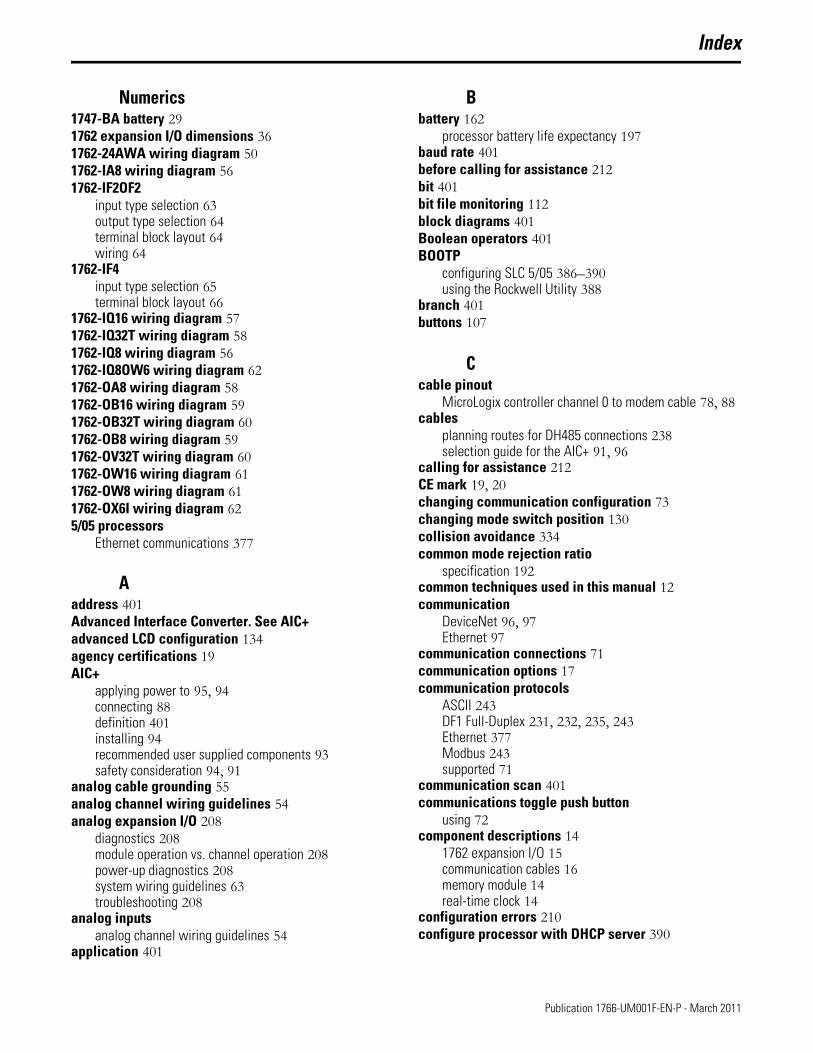
Index
Numerics1747-BA battery 291762 expansion I/O dimensions 361762-24AWA wiring diagram 501762-IA8 wiring diagram 561762-IF2OF2
input type selection 63output type selection 64terminal block layout 64wiring 64
1762-IF4input type selection 65terminal block layout 66
1762-IQ16 wiring diagram 571762-IQ32T wiring diagram 581762-IQ8 wiring diagram 561762-IQ8OW6 wiring diagram 621762-OA8 wiring diagram 581762-OB16 wiring diagram 591762-OB32T wiring diagram 601762-OB8 wiring diagram 591762-OV32T wiring diagram 601762-OW16 wiring diagram 611762-OW8 wiring diagram 611762-OX6I wiring diagram 625/05 processors
Ethernet communications 377
Aaddress 401Advanced Interface Converter. See AIC+advanced LCD configuration 134agency certifications 19AIC+
applying power to 95, 94connecting 88definition 401installing 94recommended user supplied components 93safety consideration 94, 91
analog cable grounding 55analog channel wiring guidelines 54analog expansion I/O 208
diagnostics 208module operation vs. channel operation 208power-up diagnostics 208system wiring guidelines 63troubleshooting 208
analog inputsanalog channel wiring guidelines 54
application 401
Bbattery 162
processor battery life expectancy 197baud rate 401before calling for assistance 212bit 401bit file monitoring 112block diagrams 401Boolean operators 401BOOTP
configuring SLC 5/05 386–390using the Rockwell Utility 388
branch 401buttons 107
Ccable pinout
MicroLogix controller channel 0 to modem cable 78, 88cables
planning routes for DH485 connections 238selection guide for the AIC+ 91, 96
calling for assistance 212CE mark 19, 20changing communication configuration 73changing mode switch position 130collision avoidance 334common mode rejection ratio
specification 192common techniques used in this manual 12communication
DeviceNet 96, 97Ethernet 97
communication connections 71communication options 17communication protocols
ASCII 243DF1 Full-Duplex 231, 232, 235, 243Ethernet 377Modbus 243supported 71
communication scan 401communications toggle push button
using 72component descriptions 14
1762 expansion I/O 15communication cables 16memory module 14real-time clock 14
configuration errors 210configure processor with DHCP server 390
409 Publication 1766-UM001F-EN-P - March 2011
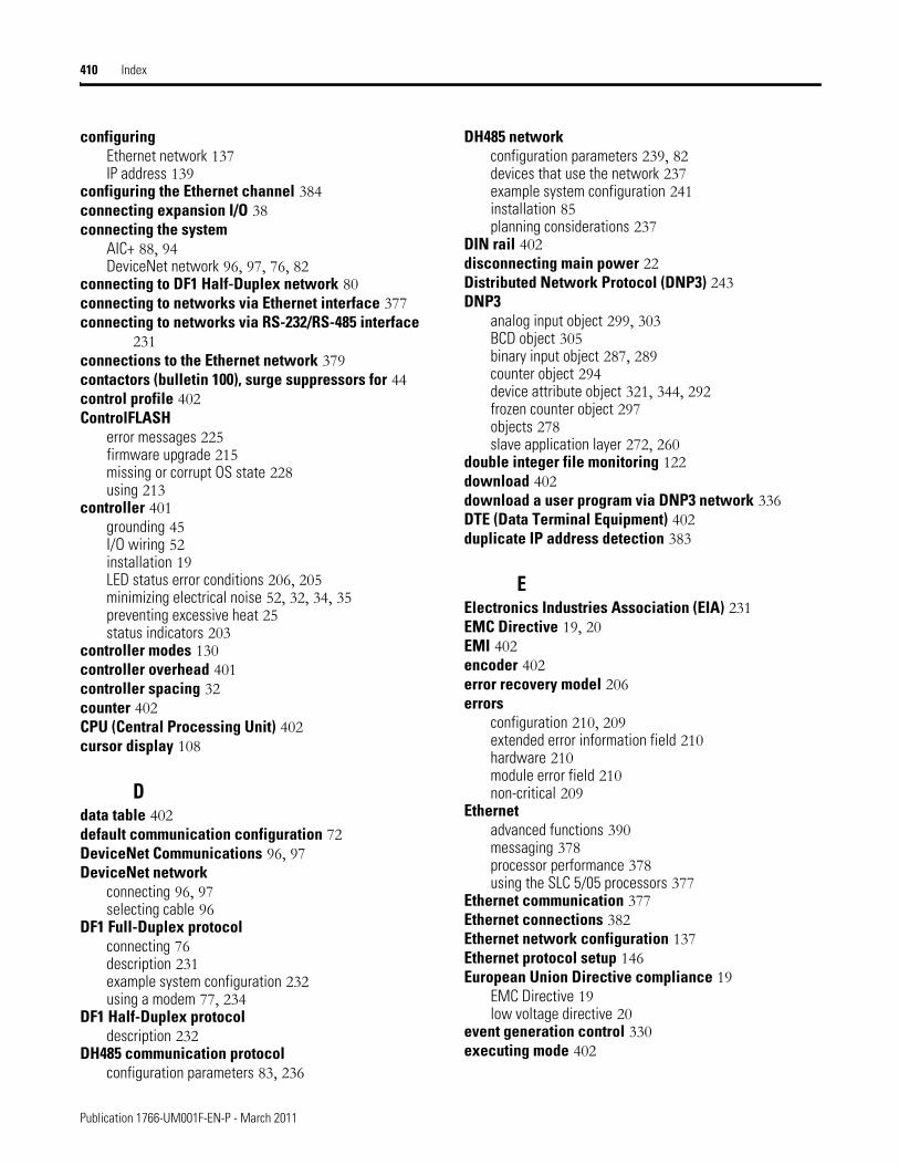
410 Index
configuringEthernet network 137IP address 139
configuring the Ethernet channel 384connecting expansion I/O 38connecting the system
AIC+ 88, 94DeviceNet network 96, 97, 76, 82
connecting to DF1 Half-Duplex network 80connecting to networks via Ethernet interface 377connecting to networks via RS-232/RS-485 interface
231connections to the Ethernet network 379contactors (bulletin 100), surge suppressors for 44control profile 402ControlFLASH
error messages 225firmware upgrade 215missing or corrupt OS state 228using 213
controller 401grounding 45I/O wiring 52installation 19LED status error conditions 206, 205minimizing electrical noise 52, 32, 34, 35preventing excessive heat 25status indicators 203
controller modes 130controller overhead 401controller spacing 32counter 402CPU (Central Processing Unit) 402cursor display 108
Ddata table 402default communication configuration 72DeviceNet Communications 96, 97DeviceNet network
connecting 96, 97selecting cable 96
DF1 Full-Duplex protocolconnecting 76description 231example system configuration 232using a modem 77, 234
DF1 Half-Duplex protocoldescription 232
DH485 communication protocolconfiguration parameters 83, 236
DH485 networkconfiguration parameters 239, 82devices that use the network 237example system configuration 241installation 85planning considerations 237
DIN rail 402disconnecting main power 22Distributed Network Protocol (DNP3) 243DNP3
analog input object 299, 303BCD object 305binary input object 287, 289counter object 294device attribute object 321, 344, 292frozen counter object 297objects 278slave application layer 272, 260
double integer file monitoring 122download 402download a user program via DNP3 network 336DTE (Data Terminal Equipment) 402duplicate IP address detection 383
EElectronics Industries Association (EIA) 231EMC Directive 19, 20EMI 402encoder 402error recovery model 206errors
configuration 210, 209extended error information field 210hardware 210module error field 210non-critical 209
Ethernetadvanced functions 390messaging 378processor performance 378using the SLC 5/05 processors 377
Ethernet communication 377Ethernet connections 382Ethernet network configuration 137Ethernet protocol setup 146European Union Directive compliance 19
EMC Directive 19low voltage directive 20
event generation control 330executing mode 402
Publication 1766-UM001F-EN-P - March 2011
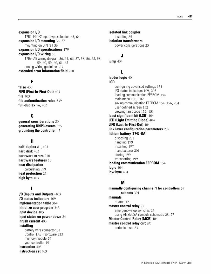
Index 411
expansion I/O1762-IF2OF2 input type selection 63, 64
expansion I/O mounting 36, 37mounting on DIN rail 36
expansion I/O specifications 179expansion I/O wiring 55
1762-IA8 wiring diagram 56, 64, 66, 57, 58, 56, 62, 58, 59, 60, 59, 60, 61, 62
analog wiring guidelines 63extended error information field 210
Ffalse 403FIFO (First-In-First-Out) 403file 403file authentication rules 339full-duplex 76, 403
Ggeneral considerations 20generating DNP3 events 325grounding the controller 45
Hhalf-duplex 81, 403hard disk 403hardware errors 210hardware features 13heat dissipation
calculating 399heat protection 25high byte 403
II/O (Inputs and Outputs) 403I/O status indicators 109implementation table 364initialize user program 343input device 403input states on power down 24inrush current 403installing
battery wire connector 31ControlFLASH software 213memory module 29your controller 19
instruction 403instruction set 403
isolated link couplerinstalling 85
isolation transformerspower considerations 23
Jjump 404
Lladder logic 404LCD
configuring advanced settings 134I/O status indicators 109, 205loading communication EEPROM 154main menu 105, 102saving communication EEPROM 154, 156, 204user defined screen 132viewing fault code 152, 151
least significant bit (LSB) 404LED (Light Emitting Diode) 404LIFO (Last-In-First-Out) 404link layer configuration parameters 252lithium battery (1747-BA)
disposing 201handling 199installing 197manufacturer 201storing 199transporting 199
loading communication EEPROM 154logic 404low byte 404
Mmanually configuring channel 1 for controllers on
subnets 391manuals
related 12master control relay 25
emergency-stop switches 26using ANSI/CSA symbols schematic 28, 27
Master Control Relay (MCR) 404master control relay circuit
periodic tests 23
Publication 1766-UM001F-EN-P - March 2011
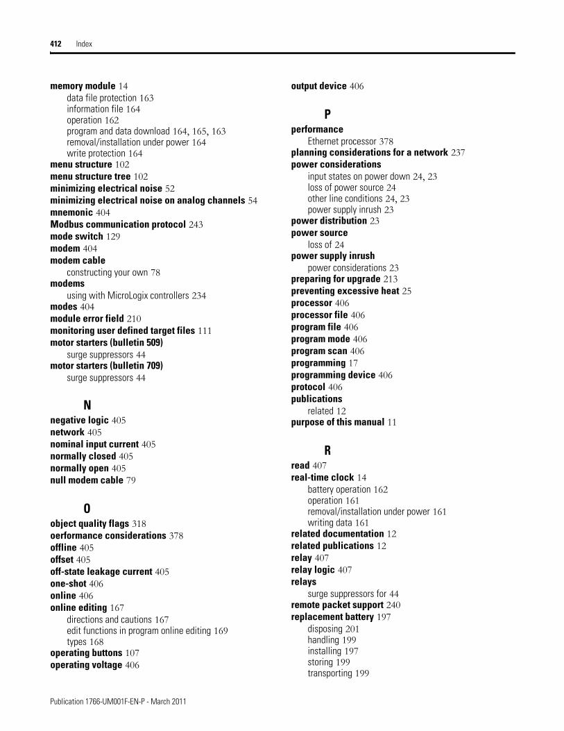
412 Index
memory module 14data file protection 163information file 164operation 162program and data download 164, 165, 163removal/installation under power 164write protection 164
menu structure 102menu structure tree 102minimizing electrical noise 52minimizing electrical noise on analog channels 54mnemonic 404Modbus communication protocol 243mode switch 129modem 404modem cable
constructing your own 78modems
using with MicroLogix controllers 234modes 404module error field 210monitoring user defined target files 111motor starters (bulletin 509)
surge suppressors 44motor starters (bulletin 709)
surge suppressors 44
Nnegative logic 405network 405nominal input current 405normally closed 405normally open 405null modem cable 79
Oobject quality flags 318oerformance considerations 378offline 405offset 405off-state leakage current 405one-shot 406online 406online editing 167
directions and cautions 167edit functions in program online editing 169types 168
operating buttons 107operating voltage 406
output device 406
Pperformance
Ethernet processor 378planning considerations for a network 237power considerations
input states on power down 24, 23loss of power source 24other line conditions 24, 23power supply inrush 23
power distribution 23power source
loss of 24power supply inrush
power considerations 23preparing for upgrade 213preventing excessive heat 25processor 406processor file 406program file 406program mode 406program scan 406programming 17programming device 406protocol 406publications
related 12purpose of this manual 11
Rread 407real-time clock 14
battery operation 162operation 161removal/installation under power 161writing data 161
related documentation 12related publications 12relay 407relay logic 407relays
surge suppressors for 44remote packet support 240replacement battery 197
disposing 201handling 199installing 197storing 199transporting 199
Publication 1766-UM001F-EN-P - March 2011
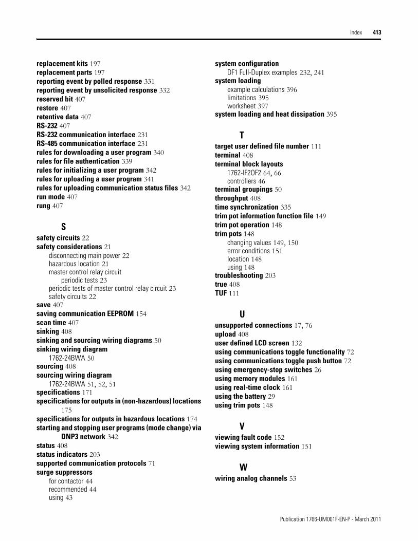
Index 413
replacement kits 197replacement parts 197reporting event by polled response 331reporting event by unsolicited response 332reserved bit 407restore 407retentive data 407RS-232 407RS-232 communication interface 231RS-485 communication interface 231rules for downloading a user program 340rules for file authentication 339rules for initializing a user program 342rules for uploading a user program 341rules for uploading communication status files 342run mode 407rung 407
Ssafety circuits 22safety considerations 21
disconnecting main power 22hazardous location 21master control relay circuit
periodic tests 23periodic tests of master control relay circuit 23safety circuits 22
save 407saving communication EEPROM 154scan time 407sinking 408sinking and sourcing wiring diagrams 50sinking wiring diagram
1762-24BWA 50sourcing 408sourcing wiring diagram
1762-24BWA 51, 52, 51specifications 171specifications for outputs in (non-hazardous) locations
175specifications for outputs in hazardous locations 174starting and stopping user programs (mode change) via
DNP3 network 342status 408status indicators 203supported communication protocols 71surge suppressors
for contactor 44recommended 44using 43
system configurationDF1 Full-Duplex examples 232, 241
system loadingexample calculations 396limitations 395worksheet 397
system loading and heat dissipation 395
Ttarget user defined file number 111terminal 408terminal block layouts
1762-IF2OF2 64, 66controllers 46
terminal groupings 50throughput 408time synchronization 335trim pot information function file 149trim pot operation 148trim pots 148
changing values 149, 150error conditions 151location 148using 148
troubleshooting 203true 408TUF 111
Uunsupported connections 17, 76upload 408user defined LCD screen 132using communications toggle functionality 72using communications toggle push button 72using emergency-stop switches 26using memory modules 161using real-time clock 161using the battery 29using trim pots 148
Vviewing fault code 152viewing system information 151
Wwiring analog channels 53
Publication 1766-UM001F-EN-P - March 2011
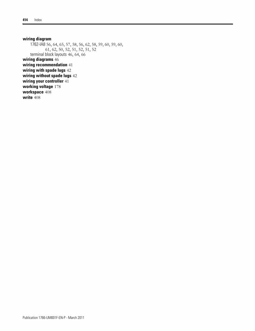
414 Index
wiring diagram1762-IA8 56, 64, 65, 57, 58, 56, 62, 58, 59, 60, 59, 60,
61, 62, 50, 52, 51, 52, 51, 52terminal block layouts 46, 64, 66
wiring diagrams 46wiring recommendation 41wiring with spade lugs 42wiring without spade lugs 42wiring your controller 41working voltage 178workspace 408write 408
Publication 1766-UM001F-EN-P - March 2011

Rockwell Otomasyon Ticaret A.Ş., Kar Plaza İş Merkezi E Blok Kat:6 34752 İçerenköy, İstanbul, Tel: +90 (216) 5698400
Publication 1766-UM001F-EN-P - March 2011 416Supersedes Publication 1766-UM001E-EN-P - May 2010 Copyright © 2011 Rockwell Automation, Inc. All rights reserved. Printed in the U.S.A.
Rockwell Automation Support
Rockwell Automation provides technical information on the Web to assist you in using its products. At http://www.rockwellautomation.com/support/, you can find technical manuals, a knowledge base of FAQs, technical and application notes, sample code and links to software service packs, and a MySupport feature that you can customize to make thebest use of these tools.
For an additional level of technical phone support for installation, configuration, and troubleshooting, we offer TechConnect support programs. For more information, contact your local distributor or Rockwell Automation representative, or visit http://www.rockwellautomation.com/support/.
Installation Assistance
If you experience a problem within the first 24 hours of installation, review the information that is contained in this manual.You can contact Customer Support for initial help in getting your product up and running.
New Product Satisfaction Return
Rockwell Automation tests all of its products to ensure that they are fully operational when shipped from the manufacturing facility. However, if your product is not functioning and needs to be returned, follow these procedures.
Documentation Feedback
Your comments will help us serve your documentation needs better. If you have any suggestions on how to improve this document, complete this form, publication RA-DU002, available at http://www.rockwellautomation.com/literature/.
United States or Canada 1.440.646.3434
Outside United States or Canada
Use the Worldwide Locator at http://www.rockwellautomation.com/support/americas/phone_en.html, or contact your local Rockwell Automation representative.
United States Contact your distributor. You must provide a Customer Support case number (call the phone number above to obtain one) to your distributor to complete the return process.
Outside United States Please contact your local Rockwell Automation representative for the return procedure.