Microcontroller Based Automatic Solar Tracking System...
12
International Journal of Sustainable and Green Energy 2015; 4(4): 125-136 Published online June 2, 2015 (http://www.sciencepublishinggroup.com/j/ijsge) doi: 10.11648/j.ijrse.20150404.11 Microcontroller Based Automatic Solar Tracking System with Mirror Booster Protik Kumar Das 1 , Mir Ahasan Habib 1 , Mohammed Mynuddin 2 1 Dept of Mechanical Engineering, Rajshahi University of Engineering & Technology (RUET), Rajshahi, Bangladesh 2 Dept of EEE, Atish Dipankar University of Science and Technology, Dhaka, Bangladesh Email address: [email protected] (P. K. Das), [email protected] (M. A. Habib), [email protected] (M. Mynuddin) To cite this article: Protik Kumar Das, Mir Ahasan Habib, Mohammed Mynuddin. Microcontroller Based Automatic Solar Tracking System with Mirror Booster. International Journal of Sustainable and Green Energy. Vol. 4, No. 4, 2015, pp. 125-136. doi: 10.11648/j.ijrse.20150404.11 Abstract: This paper is designed solar tracking system with mirror booster using microcontroller. Solar energy is rapidly becoming an alternative means of electrical source all over the world. To make effective use of solar energy, its efficiency must be maximized. A feasible approach to maximizing the power output of solar array is by sun tracking. This paper deals with the design and construction of solar tracking system by using a stepper motor, gear motor, photo diode. Mirror is used as booster to maximize the efficiency. The whole frame will travel circularly and the mirror will travel from south to north and vice-versa. The prototype is considered around a programmed microcontroller which controls the system by communicating with sensors and motor driver based on movement of the sun. The performance and characteristics of the solar tracker are experimentally analyzed. Keywords: Types of Renewable Energy, Types of Tracking Mechanism, Gear Motor, Maximize the Panel Efficiency 1. Introduction Energy is a key to the advancement and prosperity of humans. With civilization development the energy consumption has increased steadily. To sustain the current human development more energy is required in near future. The primary solution is to burn more fossil fuels [1] .But burning more and more fossil fuels will cause environmental problems such as water pollution, Air pollution, soil contamination and most dangerously greenhouse gases. The increased use of fossil fuels has significantly increased greenhouse gas emission, particularly carbon dioxide, creating an enhanced greenhouse effect known as global warming. Fossil fuels required millions of year to generate and going to finish in very short time. However, the world supplies of fossil fuels which is our main source of electricity will start to run out from the years 2020 to 2060.The increasing demand for energy, the continuous reduction in existing sources of fossil fuels and the growing concern regarding environment pollution, have pushed mankind to explore new technologies for the production of electrical energy using clean, renewable sources, such as solar energy, wind energy, etc [2]. Renewable energy resources will be an increasingly important part of power generation in the new millennium. Besides assisting in the reduction of the emission of greenhouse gases, they add the much- needed flexibility to the energy resource mix by decreasing the dependence on fossil fuels. Among the renewable energy resources, solar energy is the most essential and prerequisite resource of sustainable energy because of its ubiquity, abundance, and sustainability. Regardless of the intermittency of sunlight, solar energy is widely available and completely free of cost. Recently, photovoltaic (PV) [3]- [6] system is well recognized and widely utilized to convert the solar energy for electric power applications. Among the non-conventional, renewable energy sources, solar energy affords great potential for conversion into electric power, able to ensure an important part of the electrical energy needs of the planet. The sun is the prime source of energy, directly or indirectly, which is also the fuel for most renewable systems. Among all renewable systems, photovoltaic system is the one which has a great chance to replace the conventional energy resources. Solar panel directly converts solar radiation into electrical energy. Solar panel is mainly made from semiconductor materials. Si used as the major component of solar panels, which is maximum 24.5% efficient. Unless high efficient solar panels are invented, the only way to enhance the
Transcript of Microcontroller Based Automatic Solar Tracking System...

International Journal of Sustainable and Green Energy 2015; 4(4): 125-136 Published online June 2, 2015 (http://www.sciencepublishinggroup.com/j/ijsge) doi: 10.11648/j.ijrse.20150404.11
Microcontroller Based Automatic Solar Tracking System with Mirror Booster
Protik Kumar Das1, Mir Ahasan Habib
1, Mohammed Mynuddin
2
1Dept of Mechanical Engineering, Rajshahi University of Engineering & Technology (RUET), Rajshahi, Bangladesh 2Dept of EEE, Atish Dipankar University of Science and Technology, Dhaka, Bangladesh
Email address: [email protected] (P. K. Das), [email protected] (M. A. Habib), [email protected] (M. Mynuddin)
To cite this article: Protik Kumar Das, Mir Ahasan Habib, Mohammed Mynuddin. Microcontroller Based Automatic Solar Tracking System with Mirror Booster.
International Journal of Sustainable and Green Energy. Vol. 4, No. 4, 2015, pp. 125-136. doi: 10.11648/j.ijrse.20150404.11
Abstract: This paper is designed solar tracking system with mirror booster using microcontroller. Solar energy is rapidly becoming an alternative means of electrical source all over the world. To make effective use of solar energy, its efficiency must be maximized. A feasible approach to maximizing the power output of solar array is by sun tracking. This paper deals with the design and construction of solar tracking system by using a stepper motor, gear motor, photo diode. Mirror is used as booster to maximize the efficiency. The whole frame will travel circularly and the mirror will travel from south to north and vice-versa. The prototype is considered around a programmed microcontroller which controls the system by communicating with sensors and motor driver based on movement of the sun. The performance and characteristics of the solar tracker are experimentally analyzed.
Keywords: Types of Renewable Energy, Types of Tracking Mechanism, Gear Motor, Maximize the Panel Efficiency
1. Introduction
Energy is a key to the advancement and prosperity of humans. With civilization development the energy consumption has increased steadily. To sustain the current human development more energy is required in near future. The primary solution is to burn more fossil fuels [1] .But burning more and more fossil fuels will cause environmental problems such as water pollution, Air pollution, soil contamination and most dangerously greenhouse gases. The increased use of fossil fuels has significantly increased greenhouse gas emission, particularly carbon dioxide, creating an enhanced greenhouse effect known as global warming. Fossil fuels required millions of year to generate and going to finish in very short time. However, the world supplies of fossil fuels which is our main source of electricity will start to run out from the years 2020 to 2060.The increasing demand for energy, the continuous reduction in existing sources of fossil fuels and the growing concern regarding environment pollution, have pushed mankind to explore new technologies for the production of electrical energy using clean, renewable sources, such as solar energy, wind energy, etc [2]. Renewable energy resources will be an increasingly important part of power generation in the new millennium. Besides assisting in the reduction of the
emission of greenhouse gases, they add the much- needed flexibility to the energy resource mix by decreasing the dependence on fossil fuels. Among the renewable energy resources, solar energy is the most essential and prerequisite resource of sustainable energy because of its ubiquity, abundance, and sustainability. Regardless of the intermittency of sunlight, solar energy is widely available and completely free of cost. Recently, photovoltaic (PV) [3]-[6] system is well recognized and widely utilized to convert the solar energy for electric power applications. Among the non-conventional, renewable energy sources, solar energy affords great potential for conversion into electric power, able to ensure an important part of the electrical energy needs of the planet.
The sun is the prime source of energy, directly or indirectly, which is also the fuel for most renewable systems. Among all renewable systems, photovoltaic system is the one which has a great chance to replace the conventional energy resources. Solar panel directly converts solar radiation into electrical energy. Solar panel is mainly made from semiconductor materials. Si used as the major component of solar panels, which is maximum 24.5% efficient. Unless high efficient solar panels are invented, the only way to enhance the

126 Protik Kumar Das et al.: Microcontroller Based Automatic Solar Tracking System with Mirror Booster
performance of a solar panel is to increase the intensity of light falling on it. Solar trackers are the most appropriate and proven technology to increase the efficiency of solar panels through keeping the panels aligned with the sun’s position. Solar trackers get popularized around the world in recent days to harness solar energy in most efficient way. This is far more cost effective solution than purchasing additional solar panels [7]-[8]. In this paper the design methodology of a microcontroller based simple and easily programmed automatic solar tracker is presented. A prototype of automatic solar tracker ensures feasibility of this design methodology.
Solar tracking is necessary for most of the solar systems to collect maximum amount solar radiation. Concentrators require a high degree of accuracy to ensure that the reflected sunlight is directed to the absorber, which is at the focal point of the reflector. Sun Tracker can help increase overall efficiency of a solar installation by over 40%. The applications of solar tracking system are given below: i) Satellite dish ii) Concentrating collectors (cylindrical parabolic collector, parabolic dish collector, power tower concentrating collector etc.), iii) PV cell and iv) Flat plate collector etc.
1.1. Renewable Energy
Any energy resource that is naturally regenerated over a short time scale and derived directly from the sun (such as thermal, photochemical, and photoelectric), indirectly from the sun (such as wind, hydropower, and photosynthetic energy stored in biomass), or from other natural movements and mechanisms of the environment (such as geothermal and tidal energy) is called renewable energy [9].
1.2. Types of Renewable Energy
i) Solar energy [10], ii) Hydroelectric power [11] iii) Biomass [12] iii) From hydrogen [13] iv) Geothermal energy [14] v) Wind power [15] vi) Ocean energy [16]-[17] vii) Waste renewable energy [18]-[19]
Solar energy: Most renewable energy comes either directly or indirectly from the sun. Sunlight, or solar energy, can be used directly for heating and lighting homes and other buildings, for generating electricity, and for hot water heating, solar cooling, and a variety of commercial and industrial uses. Solar energy has many advantages: a) Need no fuel b) Has no moving parts to wear out c)Non-polluting & quick responding d) Adaptable for on-site installation e) Easy maintenance f) Can be integrated with other renewable energy sources g) Simple & efficient and so on.
1.3. Application of Renewable Energy
Renewable energy is of many uses and it can support small as well as large applications. Renewable energy from wind, sun and geothermal is used to produce electricity and heat for use. The solar power plants are used to generate electricity and steam for industrial projects. The energy form the geothermal heat is used to heat radiators in the homes. Thus the renewable energy sources can viably help users to their
heat homes. Some other applications of renewable energy sources include heating space, to generate electricity, solar oven, ventilation, day lighting, space cooling, water heating, mechanical energy to cut woods and grinding grains. The renewable energy sources and the technologies associated with them are equally important to households and industry. Renewable energy sources are of many uses to domestic users.
1.4. Solar Energy
Solar energy is the term used for the heat and light which the sunlight contains. Sunlight reaches to earth in the form of photons. Photons are energy packets that contain light in it. Solar energy is considered as a renewable energy source because it does not destroy our eco system and is present naturally in the environment.
1.5. Electricity from Solar Power
Solar power is the form of energy that helps in generation of electricity from the sunrays. There are many methods to generate electric current using sunlight but the most common methods are photovoltaic and concentrated solar power. Photovoltaic contains an array of solar cells which are pressed in solar panels. These solar panels are protected and framed by a glass sheet. This sheet does not allow any impurities to pass in. Hence only sunrays can make their way in. These solar panels are made up of conductive materials like impure silicon and copper indium mostly. These conductors help and support the flow of electrons, thus the heat present on the solar panels is able to generate direct electric current. This electric current cannot support the electrical devices. Therefore it is converted to alternative current by using inverter and battery. Photovoltaic energy is growing rapidly and it is so far the only rapidly progressing renewable energy technology. Concentrating solar power (CSP) [20] systems work on the principle of converging the sunlight form many kilometers to single focal point. The concentrated energy stored in this form is converted to thermal energy which is utilized to support photovoltaic cell. The solar energy stored by CSP is also helpful in running steam turbines.
1.6. Types of Solar Energy System
Solar energy systems are of many types dependent upon their use. These include concentrating solar power systems, parabolic dishes, sunlight Stirling dishes, updraft towers, photovoltaic and solar ponds. All these systems are used to generate electricity in an economical and environment friendly manner. Photovoltaic solar panels are also used to heat water. The steam produced in this process is used for running the industrial machinery. Concentrating solar systems uses lenses, tracking system and glass to convert the sunlight into single beam. The heat stored in this way is used to support the conventional power houses. Parabolic dishes are another system which is used save solar energy. These parabolic antennas work on the mechanism of tracking

International Journal of Sustainable and Green Energy 2015; 4(4): 125-136 127
through single axis. Stirling solar dish systems contain a parabolic reflector that gathers the light to single focal point onto as a receiver. The updraft solar systems work by running wind turbines connected to it. These wind turbines produce electricity which is stored in the form of direct current in collectors at one end. Solar ponds were constituted to perform an experiment over the layers of salt present in red sea. The heat from the sun is stored into the lower bed of salt. This heat is then used to heat water in collectors.
1.7. The Development in Solar Power System
The development in solar power systems took place when human beings realized that the bio fuels like coal and oil will not be sufficient to produce electricity in future. The development of solar energy systems faced many hindrances because of the unavailability of solar heating system and its equipment’s. It was in 1973 again when the fuel and oil crisis reached to the peak. The desire to find alternative energy sources again became the need of time. Hence form that time developed countries like USA star deploying solar panels on barren land to cater the expected deficiency of bio fuels in future. Soon after wards in 1985 when the prices of oil feel again the development and attention toward solar systems declined once again. It is now again that we need renewable energy sources to fight the problem of global warming and pollution. Therefore sunlight is the only energy source which provides electricity for industrial consumption without producing any harmful waste. However the commercial production of solar cells has resulted in its deployment even in residents. The governments throughout the world are giving great incentives to industry and individuals to switch to this major energy sources. Solar energy systems are great way to utilize abundant solar energy to support unlimited commercial and domestic applications.
1.8. Advantages of Solar Power Energy
The importance and advantages of solar energy and its uses were not even declined in prehistoric times. Sunlight helps plants to generate food for them during the process of photosynthesis. Solar power energy free of cost energy source helped people store their food for longer when refrigerators were not in use, people used it for killing germs in clothes and most importantly this useful star provides us vitamin D to support healthy growth of our bones. Nowadays the practices of using solar energy are changing as it has been identified as an inexpensive way to produce electricity.
1.9. Storage of Solar Energy
Producing electricity from sun is also termed as a renewable solar energy source. Renewable energy source refers to all those energy sources other than traditional bio fuels. Solar energy is of many uses. When the process of generating electricity was under consideration, the major challenge was to store solar energy to be used later in night, storms and rains. Hence useful devices like solar panels, solar heating systems and solar cells supported this immense
challenge. Solar energy can be used unless we have sun. Hence all the solar power applications can help us utilize solar energy rays to produce electricity for supporting personal, domestic and industrial applications. Now it is possible to store solar energy in batteries which are attached to the solar powers panels. The electricity generated through solar energy process can be used with or without traditional utility grids. Another experiment carried at the red sea demonstrated that solar energy can also be stored in the beds of salt to support solar heating systems.
2. Photovoltaic Cell and Solar Tracking
System
2.1. Solar Panel
A solar panel is a set of solar photovoltaic modules electrically connected and mounted on a supporting structure. A photovoltaic module is a packaged, connected assembly of solar cells. The solar module can be used as a component of a larger photovoltaic system to generate and supply electricity in commercial and residential applications. Each module is rated by its DC output power under standard test Condit Solar modules use light energy (photons) from the sun to generate electricity through the photovoltaic effect. The majority of modules use wafer-based crystalline silicon cells or thin-film cells based on cadmium telluride or silicon. The structural (load carrying) member of a module can either be the top layer or the back layer. Cells must also be protected from mechanical damage and moisture. Most solar modules are rigid, but semi-flexible ones are available, based on thin-film cells.
Fig. 1. A Typical Solar Panel.
2.2. Principle of Photovoltaic Cell
Photovoltaic (PV) [21] system is well recognized and widely utilized to convert the solar energy for electric power applications. It can generate direct current (DC) electricity without environmental impact and emission by way of solar radiation. The DC power is converted to AC power with an inverter, to power local loads or fed back to the utility. Being a semiconductor device, the PV systems are suitable for most operation at a lower maintenance costs.

128 Protik Kumar Das et al.: Microcontroller Based Automatic Solar Tracking System with Mirror Booster
Fig. 2. Principle of photovoltaic cell.
2.3. Solar Tracker
Solar tracker is rack for photovoltaic modules that move to point at or near the sun throughout the day. Trackers add to the efficiency of the system, reducing its size and the cost per KWH.A solar tracker is a generic term used to describe devices that orient various payloads toward the sun. Payloads can be photovoltaic panels, reflectors, lenses or other optical devices.
2.4. Tracking Technique
There are several forms of tracking currently available, these vary mainly in the used are fixed control algorithms and dynamic tracking. The inherent difference between the two methods is the manner in which the path of the sun is determined. In the fixed control algorithm systems, the path of the sun is determined by referencing an algorithm that calculates the position of the sun for each time period. That is, the control system does not actively find the sun's position but works it out given the current time, day, month, and year. The dynamic tracking system, on the other hand, actively searches for the sun's position at any time of day or night. Control system is common for both tracking techniques. This system consists of some method of direction control, such as DC motors, stepper motors, and servo motors, which are directed by a control circuit, either digital or analog.
2.5. Types of Solar Collector
Different types of solar collector and their location (latitude) require different types of tracking mechanism. Solar collectors may be: i) non-concentrating flat-panels, usually photovoltaic or hot-water, ii) Concentrating systems, of a variety of types.
Solar collector mounting systems may be fixed (manually aligned) or tracking. Tracking systems may be configured as: i) Fixed collector / moving mirror ii) Moving collector
Fixed mount: Domestic and small-scale commercial photovoltaic and hot-water panels are usually fixed, often flush-mounted on an appropriately facing pitched roof. Advantages of fixed mount systems (i.e. factors tending to indicate against trackers) include the following :i) Mechanical simplicity: and hence lower installation and ongoing maintenance costs ii) Wind-loading: it is easier and
cheaper to provision a sturdy mount; all mounts other than fixed flush-mounted panels must be carefully designed having regard to their wind loading due to their greater exposure iii) Indirect light: approximately 10% of the incident solar radiation is diffuse light, available at any angle of misalignment with the direct sun and iv) Tolerance to misalignment: effective collection area for a flat-panel is relatively insensitive to quite high levels of misalignment with the sun – see table and diagram at Accuracy Requirements section below – for example even a 25° misalignment reduces the direct solar energy collected by less than 10%. Fixed mounts are usually used in conjunction with non-concentrating systems, however an important class of non-tracking concentrating collectors, of particular value in the 3rd world, are portable solar cookers. These utilize relatively low levels of concentration, typically around 2 to 8 Suns and are manually.
Fixed collector or moving mirror: Many collectors cannot be moved, for example high-temperature collectors where the energy is recovered as hot liquid or gas (e.g. steam). Other examples include direct heating and lighting of buildings and fixed in-built solar cookers, such as Schaffer reflectors. In such cases it is necessary to employ a moving mirror so that, regardless of where the Sun is positioned in the sky, the Sun's rays are redirected onto the collector. Due to the complicated motion of the Sun across the sky, and the level of precision required to correctly aim the Sun's rays onto the target, a heliostat mirror generally employs a dual axis tracking system, with at least one axis mechanized. In different applications, mirrors may be flat or concave.
Non-Concentrating Photovoltaic (PV) Trackers: Photovoltaic panels accept both direct and diffuse light from the sky. The panels on a Standard Photovoltaic Trackers always gather the available direct light. The tracking functionality in Standard Photovoltaic Trackers is used to minimize the angle of incidence between incoming light and the photovoltaic panel. This increases the amount of energy gathered from the direct component of the incoming light.
2.6. Concentrated Photovoltaic (CPV) Trackers
The optics in CPV modules accept the direct component of the incoming light and therefore must be oriented appropriately to maximize the energy collected. In low concentration applications a portion of the diffuse light from the sky can also be captured. The tracking functionality in CPV modules is used to orient the optics such that the incoming light is focused to a photovoltaic collector. CPV modules that concentrate in one dimension must be tracked normal to the sun in one axis. CPV modules that concentrate in two dimensions must be tracked normal to the sun in two axes.
2.7. Single Axis Trackers
The axis of rotation of single axis trackers is typically aligned along a true North meridian. It is possible to align
International Journal of Sustainable and Green Energy 2015; 4(4): 125-136 129
them in any cardinal direction with advanced Single axis trackers have one degree of freedom that acts as an axis of rotation tracking algorithms. There are several common implementations of single axis trackers. These include horizontal single axis trackers (HSAT), vertical single axis trackers (VSAT), tilted single axis trackers (TSAT) and polar aligned single axis trackers (PSAT). The orientation of the module with respect to the tracker axis is important when modeling performance.
Fig. 3. Single axis tracker.
2.7.1. Horizontal Single Axis Tracker (HSAT)
The axis of rotation for horizontal single axis tracker is horizontal with respect to the ground. The posts at either end of the axis of rotation of a horizontal single axis tracker can be shared between trackers to lower the installation cost. Field layouts with horizontal single axis trackers are very flexible. The simple geometry means that keeping the entire axis of rotation parallel to one another is all that is required for appropriately positioning the trackers with respect to one another. Appropriate spacing can maximize the ratio of energy production to cost, this being dependent upon local terrain and shading conditions and the time-of-day value of the energy produced. Backtracking is one means of computing the disposition of panels. Horizontal Trackers typically have the face of the module oriented parallel to the axis of rotation. As a module tracks, it sweeps a cylinder that is rotationally symmetric around the axis of rotation. Several manufacturers can deliver single axis horizontal trackers. In these, a long horizontal tube is supported on bearings mounted upon pylons or frames. The axis of the tube is on a North-South line. Panels are mounted upon the tube, and the tube will rotate on its axis to track the apparent motion of the sun through the day.
Fig. 4. Horizontal Single Axis Tracker in California.
2.7.2. Vertical Single Axis Tracker (VSAT)
The axis of rotation for vertical single axis trackers is vertical with respect to the ground. These trackers rotate from East to West over the course of the day. Such trackers are more effective at high latitudes than are horizontal axis trackers. Field layouts must consider shading to avoid unnecessary energy losses and to optimize land utilization. Also optimization for dense packing is limited due to the nature of the shading over the course of a year. Vertical single axis trackers typically have the face of the module oriented at an angle with respect to the axis of rotation. As a module tracks, it sweeps a cone that is rotationally symmetric around the axis of rotation.
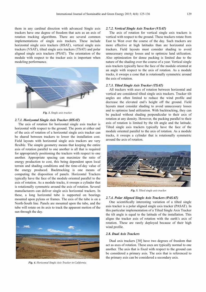
2.7.3. Tilted Single Axis Tracker (TSAT)
All trackers with axes of rotation between horizontal and vertical are considered tilted single axis trackers. Tracker tilt angles are often limited to reduce the wind profile and decrease the elevated end’s height off the ground. Field layouts must consider shading to avoid unnecessary losses and to optimize land utilization. With backtracking, they can be packed without shading perpendicular to their axis of rotation at any density. However, the packing parallel to their axis of rotation is limited by the tilt angle and the latitude. Tilted single axis trackers typically have the face of the module oriented parallel to the axis of rotation. As a module tracks, it sweeps a cylinder that is rotationally symmetric around the axis of rotation.
Fig. 5. Tilted single axis tracker.
2.7.4. Polar Aligned Single Axis Trackers (PASAT)
One scientifically interesting variation of a tilted single axis tracker is a polar aligned single axis tracker (PASAT). In this particular implementation of a Tilted Single Axis Tracker the tilt angle is equal to the latitude of the installation. This aligns the tracker axis of rotation with the earth’s axis of rotation. These are rarely deployed because of their high wind profile.
2.8. Dual Axis Trackers
Dual axis trackers [30] have two degrees of freedom that act as axes of rotation. These axes are typically normal to one another. The axis that is fixed with respect to the ground can be considered a primary axis. The axis that is referenced to the primary axis can be considered a secondary axis.

130 Protik Kumar Das et al.: Microcontroller Based Automatic Solar Tracking System with Mirror Booster
Fig. 6. Dual axis tracker.
There are several common implementations of dual axis trackers. They are classified by the orientation of their primary axes with respect to the ground. Two common implementations are tip-tilt dual axis trackers (TTDAT) and azimuth-altitude dual axis trackers (AADAT).The orientation of the module with respect to the tracker axis is important when modeling performance. Dual axis trackers typically have modules oriented parallel to the secondary axis of rotation. Dual axis trackers allow for optimum solar energy levels due to their ability to follow the sun vertically and horizontally. No matter where the sun is in the sky, dual axis trackers are able to angle themselves to be in direct contact with the sun.
2.8.1. Tip–Tilt Dual Axis Tracker (TTDAT)
A tip–tilt dual axis tracker has its primary axis horizontal to the ground. The secondary axis is then typically normal to the primary axis. The posts at either end of the primary axis of rotation of a tip–tilt dual axis tracker can be shared between trackers to lower installation costs. Field layouts with tip–tilt dual axis trackers are very flexible. The simple geometry means that keeping the axes of rotation parallel to one another is all that is required for appropriately positioning the trackers with respect to one another. In addition, with backtracking, they can be packed without shading at any density The axes of rotation of tip–tilt dual axis trackers are typically aligned either along a true North meridian or an east west line of latitude. It is possible to align them in any cardinal direction with advanced tracking algorithms. Manufacturers include Patriot Solar Group.
2.8.2. Azimuth-Altitude Dual Axis Tracker (AADAT)
An azimuth–altitude dual axis tracker has its primary axis vertical to the ground. The secondary axis is then typically normal to the primary axis. Field layouts must consider shading to avoid unnecessary energy losses and to optimize land utilization. Also optimization for dense packing is limited due to the nature of the shading over the course of a year.
This mount is used as a large telescope mount owing to its structure and dimensions. One axis is a vertical pivot shaft or horizontal ring mount that allows the device to be swung to a compass point. The second axis is a horizontal elevation pivot mounted upon the azimuth platform. By using combinations of the two axis, any location in the upward
hemisphere may be pointed. Such systems may be operated under computer control according to the expected solar orientation, or may use a tracking sensor to control motor drives that orient the panels toward the sun. This type of mount is also used to orient parabolic reflectors that mount a Sterling engine to produce electricity at the device.
Fig. 7. Azimuth-altitude dual axis tracker - 2 axis solar tracker, Toledo,
Spain.
2.9. Tracker Type Selection
The selection of tracker type is dependent on many factors including installation size, electric rates, government incentives, land constraints, latitude, and local weather. Horizontal single axis trackers are typically used for large distributed generation projects and utility scale projects. The combination of energy improvement and lower product cost and lower installation complexity results in compelling economics in large deployments. In addition the strong afternoon performance is particularly desirable for large grid-tied photovoltaic systems so that production will match the peak demand time. Horizontal single axis trackers also add a substantial amount of productivity during the spring and summer seasons when the sun is high in the sky. The inherent robustness of their supporting structure and the simplicity of the mechanism also result in high reliability which keeps maintenance costs low. Since the panels are horizontal, they can be compactly placed on the axle tube without danger of self-shading and are also readily accessible for cleaning. A vertical axis tracker pivots only about a vertical axle, with the panels either vertical, at a fixed, adjustable, or tracked elevation angle. Such trackers with fixed or (seasonably) adjustable angles are suitable for high latitudes, where the apparent solar path is not especially high, but which leads to long days in summer, with the sun travelling through a long arc. Dual axis trackers are typically used in smaller residential installations and locations with very high government Feed in Tariffs.
2.10. Multi-Mirror Concentrating PV
This device uses multiple mirrors in a horizontal plane to reflect sunlight upward to a high temperature photovoltaic or other system requiring concentrated solar power. Structural problems and expense are greatly reduced since the mirrors are not significantly exposed to wind loads. Through the employment of a patented mechanism, only two drive

International Journal of Sustainable and Green Energy 2015;
systems are required for each device. configuration of the device it is especiallyflat roofs and at lower latitudes. The unitsproduce approximately 200 peak DC watts.reflective system combined with a centralemployed at the Sierra Sun Tower, locatedCalifornia. This generation plant operatedscheduled to begin operations on Augustsystem, which uses multiple heliostats alignment, uses pre-fabricated parts and way of decreasing startup and operating costs.
2.11. Advantage of Solar Tracker
The main reason to use a solar tracker isof the energy we want to capture. A trackerpower over a longer time than a stationarysame number of modules. This additionalcan be quantified as a percentage of thestationary array. Gain varies significantlyclimate, and the type of tracker you chooseorientation of a stationary installation in the(The energy required to move the tracker these calculations.) Climate is the most importantmore sun and less clouds, moisture, haze, dust,greater the gain provided by trackers. At higherwill be increased due to the long arc of the
3. Methodology
3.1. Project Design Methodology
Fig. 8. Block diagram of project design methodology
Design System: Firstly to build a solar tracker designing
need. The solar panel is fastened to the frame,mirror to improve the design. The mirror willthe fall of the sun rays upon the panel. Thedesign criteria depends are:i) DimensionCapacity of the panel iii)Selection of structuralSelection of gear motor and v) Space available
Foundations: For balancing the solarfoundation is a very important thing.
International Journal of Sustainable and Green Energy 2015; 4(4): 125-136
Because of the especially suited for use on
units illustrated each watts. A multiple mirror central power tower is
located in Lancaster, operated by e Solar is
August 5, 2009. This in a north-south construction as a
costs.
is to reduce the cost tracker produces more
stationary array with the additional output or “gain”
the output of the significantly with latitude,
choose—as well as the the same location. is insignificant in
important factor. The dust, and smog, the
higher latitudes gain summer sun.
methodology.
designing model is a basic frame, as well as the will help to increase
The factors in which Dimension of the panel ii)
structural material iv) available. solar tracker a good
thing. Secondly basic
Foundation is needed to implementfoundation should have adequatesystem.
Fig. 9. Foundation of
Building Frame: To set the solaralso an important thing. The panelframe.
Mounting the Solar Panel: Herefasten the panel to the frame has
Fig .10. Mounting the
Wire and Program Controller:control the motor program is setsystem.
3.2. Boosting the Solar Panel
Solar panels are a great electricity for our home or workplaceexpensive and sometimes the wattagedisappointing. If we use a sunpanels facing the sun we can considerablyyield but these are not cheap andadd considerably to the cost. and simple way to get 75% moresolar panel. Most of the time below peak power, on hazy daysthe sky, early morning, and late
136 131
implement this project. The adequate strength to hold the total
of the solar tracker.
solar system building a frame is panel & mirror are stay in the
Here to mount the solar panel, has done.
the panel on the frame.
Controller: Proper wiring system, to set & also to control the overall
way to make some green workplace but they’re kind of wattage produced can be a bit
sun tracking system to keep our considerably improve the watt
and on a small system they can Here’s a really cost effective
more power from any ordinary a solar panel is working well
days and when the sun is lower in late afternoon for example. The

132 Protik Kumar Das et al.: Microcontroller Based Automatic Solar Tracking System with Mirror Booster
light levels are just not high enough, so to boost the light level aligning a mirror will reflect more light onto solar panel. It worked really well and after a bit of experimentation it was found that placing a mirror at least twice the size of the solar panel on the ground in front of the panel could boost the output by as much as 75%.
Fig. 11. Solar panel boosting with mirror [22].
Using a bigger mirror can reflect light onto panel over a longer period during the day so tracking the sun is not needed, just face the panel and mirror due south[23]. This is probably one of the cheapest and easiest ways to boost the power of a small solar panel, but this method does have some limitations. Using more mirrors to reflect more light onto the solar panel increase its power further but on a sunny summer’s day the extra light can build up a lot of heat that may damage the panel. Placing mirrors either side of the panel to reflect doesn't work well because as the sun moves west it will cast a shadow across the panel. The only place that the mirror won't cast a shadow at any time in the day is on the ground in front of the solar panel. On a dull day the mirror doesn't give much of a power boost at all.
4. Microcontroller
4.1. Microcontroller
A microcontroller is a small computer on a single integrated circuit containing a processor core, memory, and programmable input/output peripherals. The Program memory in the form of NOR flash or OTP ROM is also often included on chip, as well as a typically small amount of RAM. Microcontrollers are designed for embedded applications, in contrast to the microprocessors used in personal computers or other general purpose applications. Microcontrollers [31] are used in automatically controlled products and devices, such as automobile engine control systems, implantable medical devices, remote controls, office machines, appliances, power tools, toys and other embedded systems. By reducing the size and cost compared to a design that uses a separate microprocessor, memory, and input/output devices, microcontrollers make it economical to digitally control even more devices and processes. Mixed
signal microcontrollers are common, integrating analog components needed to control non-digital electronic systems [25]. ATmega 8 microcontroller [23]-[25] is used for controlling the direction of DC Gear motor.
Advantage used of Microcontroller
Microcontrollers, as stated, are inexpensive computers .The microcontroller has ability to store and run a unique program makes it extremely versatile. For instance one can program a microcontroller to makes decisions based on predetermined situations and selections .The microcontroller has ability to perform math and logic functions allows it to mimic sophisticated logic and electronic circuit.
4.2. Photodiode Sensor
The construction of the Photodiode light sensor is similar to that of a conventional PN junction diode except that the diodes outer casing is either transparent or has a clear lens to focus the light onto the PN junction for increased sensitivity. The junction will respond to light particularly longer wavelengths such as red and infra-red rather than visible light. This characteristic can be a problem for diodes with transparent or glass bead bodies such as the 1N4148 signal diode. LED’s can also be used as photodiodes as they can both emit and detect light from their junction. All PN-junctions are light sensitive and can be used in a photo-conductive unbiased voltage mode with the PN-junction of the photodiode always “Reverse Biased” so that only the diodes leakage or dark current can flow.
The current-voltage characteristic (I/V Curves) of a photodiode with no light on its junction (dark mode) is very similar to a normal signal or rectifying diode. When the photodiode is forward biased, there is an exponential increase in the current, the same as for a normal diode. When a reverse bias is applied, a small reverse saturation current appears which causes an increase of the depletion region, which is the sensitive part of the junction. Photodiodes can also be connected in a current mode using a fixed bias voltage across the junction. The current mode is very linear over a wide range.
4.3. Gear Motor
The DC Gear motor, consisting of a DC electric motor and a gearbox, is at the heart of several electrical and electronic applications. Precision Micro drive’s have been designing and developing such high quality mini DC gear motors in an easy-to-mount package for a range of products and equipment. The miniature gear motor work smoothly and efficiently, supporting these electrical and electronic applications. These geared motors have reduction gear trains capable of providing high torque at relatively low shaft speed or revolutions per minute (RPM). Precision Micro drive’s DC geared motors reduce the complexity and cost of designing and constructing applications such as industrial equipment, actuators, medical tools, and robotics. The voltage is regulated by using LM7805 [27] voltage regulator.

International Journal of Sustainable and Green Energy 2015;
Fig. 12. Geared motor.
5. Experimental Implementation
5.1. Total Arrangement of the System
Fig. 13. Total arrangement of the system.
5.2. Working Principle
Photodiode is used as sensors. Two photodiodesensing the position of the panel and two photodiodeto sensing the mirror position for boostingvoltage drop between the two sensors of panelsignal will go to the microcontroller,calculates the ADC [28] value. Then the ADCmotor driver A. Motor A will rotate the panel.the voltage drop of two sensors of the mirrorsignal will go to the microcontroller,calculates the ADC value. Then the ADCmotor driver B and motor B control the boosting the panel efficiency.
Fig. 14. Block diagram of the system
International Journal of Sustainable and Green Energy 2015; 4(4): 125-136
Implementation
system.
photodiode are used to photodiode are used
boosting the panel. If panel is not same a
microcontroller, Microcontroller ADC value it goes to
panel. Again when mirror is not same, a
microcontroller, microcontroller value goes to the
mirror position to
system.
5.3. Circuit Diagram of the System
Fig. 15. Circuit diagram
5.4. Experimental Procedure
The experimental result is dependsArea of the PV cell iii) Voltageset on the direction of the sun.position perfect, it will track light of sun by its sensors. Thusfound. Then by using millimetercurrent is noted down. The photovoltaicgive the solar intensity for differentmeasuring theses values, the powerand its efficiency can be calculated.
Fig. 16. Automatic
Fig. 17. Multimeter
136 133
System
diagram of the system.
depends on i) Solar intensity ii) Voltage iv) Current. The total system
sun. If the panel does not get its automatically the maximum
Thus a current & voltage drop is millimeter , the readings of voltage and
photovoltaic trainer instruments different period of time. By
power output of the solar panel calculated.
Automatic solar tracker.
Multimeter.

134 Protik Kumar Das et al.: Microcontroller Based Automatic Solar Tracking System with Mirror Booster
5.5. Calculation of Intensity
The relationship between radiant sun light and electrical power generated can be demonstrated with the aid of measuring equipment called photovoltaic Trainer. The sun intensity i (w/m2) can be calculated by this There are following things in photovoltaic trainer: a) Tilting Support on Caster b) Variable Resistor with slider c) Solar Module d) Temperature Sensor e) I luminance Sensor and f) Connector of the Solar Module.
Fig. 18. Photovoltaic trainer showing intensity and temperature.
6. Results and Discussions
6.1. Description
From Fig 19 to Fig 23 shows the tracking results using microcontroller and mirror. These figures are based on intensity, current, power and efficiency on the basis of Appendix-A.
6.2. Intensity Vs. Day Time Curve
Intensity increase with respect to the day time and after 1 pm the intensity decreases. The graph shows right fulfill the all condition of Power vs. Day time graph.
Fig. 19. Intensity vs. Day time curve.
6.3. Current Vs. day Time Curve
This graph shows that at first current increases and then decrease with the increase of day time. As the intensity
increase the current also increase and as the intensity decrease the current also decrease.
Fig. 20. Current vs. Day time curve.
6.4. Power Vs. Day Time Curve
Power increase with respect to the day time because intensity increases. After 1 pm the intensity decreases so the powers automatically decrease. This graph shows difference of power output between with tracking and without tracking.
Fig. 21. Power vs. Day time curve.
6.5. Efficiency Vs. Day Time Curve
This graph represents that panel efficiency increase with respect to the day time because voltage, current and intensity increase. After 1pm the voltage, current and intensity decreases so the efficiency automatically decrease.
Fig. 22. Efficiency vs. Day time curve.

International Journal of Sustainable and Green Energy 2015; 4(4): 125-136 135
6.6. Power Vs. Day Time Curve
Power increase with respect to the day time because intensity increases. After 1 pm the intensity decreases so the powers automatically decrease. The graph shows right fulfill the all condition of Power vs. Day time graph. From the graph we observed that the power out-put of solar panel with mirror is greater than without mirror.
Fig. 23. Power vs. Day time curve.
7. Conclusions
The microcontroller based solar tracking system with mirror booster has been fabricated. The efficiency of solar panel is 9%. The paper has been presented a novel and a simple control implementation of a Sun tracker that employed to follow the Sun and produce electricity. The proposed two-motor design is simple and self-contained, and do not require any programming and a computer interface. The proposed methodology is an innovation so far. It achieves the following attractive features are simple and cost-effective control implementation, bulky but it is effective for large power generation, Battery will not take any charge after it is fully charged. This will increase battery’s life time. Photo-diode is used instead of LDR sensor because; it can only take infra-red. Gear motor is used because it gives more power than stepper motor.
Sample calculations 1: Solar panel length=0.25 m Width=0.16 m Area of the panel=Length x width =0.25 x 0.16=0.04 m2
V=14.57v I=0.31A Power, P=14.57 x 0.31 =4.51 watt Efficiency= (V x I)/ (A x i) = (14.57 x 0.31)/ (0.04 x 1256) =8.99 % Sample calculations 2: V= 14.49v I=0.30A Power, P=V x I=14.49 x 0.30=4.377 Efficiency= (V x I)/ (A x i) = (14.49 x 0.30)/ (1256 x 0.04) =8.6%
References
[1] A. J. Sangster. Engineering the Early Demise of Fossil Fuels “International Journal of Sustainable and Green Energy” Vol. 3, No. 6, 2014, pp. 115-122. doi: 10.11648/j.ijrse.20140306.11
[2] Feltrin, A., Freundlich, A., Material considerations for terawatt level deployment of photovoltaics. Renewable Energy, volume 33, 2008, Pages 180-185.
[3] K. H. Hussein et al, “Maximum Photovoltaic Power Tracking: An Algorithm for rapidly changing atmospheric conditions,” Proc. Inst. Elect. Eng. volume 142, pt. G, no.1, January 1995, Pages 59–64.
[4] C.S. Chin, A. Babu, W. McBride. Design,modeling & testing of a standalone single axis active solar tracker using MATLAB/Simulink.
[5] C.R. Sullivan and M.J. Powers,“A High-Efficiency Maximum Power Point Tracking for Photovoltaic Arrays in a Solar-Power Race Vehicle”, IEEE PESC‘93, 1993, Pages 574-580.
[6] Xuejun Liu and A.C.Lopes,,“An Improved Perturbation and Observe Maximum Power Point Tracking Algorithm for PV Arrays” IEEE PESC ‘2004, Pages 2005-2010.
[7] Rashmi Swami"Solar Cell" International Journal of Scientific and Research Publications, Volume 2, Issue 7, July 2012,pp 1-5
[8] Sayran A. Abdulgafar 1, Omar S. Omar 2 ,Kamil M. Yousif 3 "Improving The Efficiency Of Polycrystalline Solar Panel Via Water Immersion Method"International Journal of Innovative Research in Science,Engineering and Technology,pp8127-8132.
[9] http://www.geo.lu.lv/fileadmin/user_upload/lu_portal/projekti/gzzf/videunilgtspejigaattistiba/VidZ1000/7.LECTURE-Energy_resources.pdf
[10] http://aerostudents.com/files/solarCells/solarCellsTheoryFullVersion.pdf
[11] Kumar, A., T. Schei, A. Ahenkorah, R. Caceres Rodriguez, J.-M. Devernay, M. Freitas, D. Hall, Å. Killingtveit, Z. Liu, 2011: Hydropower. In IPCC Special Report on Renewable Energy Sources and Climate Change Mitigation [O. Edenhofer, R. Pichs-Madruga, Y. Sokona, K. Seyboth, P. Matschoss, S. Kadner, T. Zwickel, P. Eickemeier, G. Hansen, S. Schlömer, C. von Stechow (eds)], Cambridge University Press, Cambridge, United Kingdom and New York, NY, USA.
[12] http://www.energy.gov/eere/bioenergy/bioenergy-technologies-office
[13] http://www.nrel.gov/docs/fy08osti/39146.pdf
[14] http://energy.gov/eere/geothermal/geothermal-basics
[15] http://web.mit.edu/windenergy/windweek/Presentations/Wind%20Energy%20101.pdf
[16] http://energy.gov/eere/energybasics/articles/wave-energy-basics
[17] http://folk.ntnu.no/falnes/teach/wave/JF_introduction2010-06-28.pdf

136 Protik Kumar Das et al.: Microcontroller Based Automatic Solar Tracking System with Mirror Booster
[18] http://www.e-renewables.com/documents/Waste/Waste%20to%20Energy%20-%20The%20Basics.pdf
[19] http://www.r-e-a.net/pdf/energy-from-waste-guide-for-decision-makers.pdf
[20] Yingxue Yao, Yeguang Hu, Shengdong Gao, Gang Yang, Jinguang. A multiple dual-axis solar tracker with two tracking strategies. Renewable Energy, Volume 72, December 2014, Pages 88-98.
[21] Kroposki B, DeBlasio R, (2000), Technologies for the New Millennium: Photovoltaics as a Distributed Resource, IEEE Power Engineering Society Summer Meeting, pages 1798 – 1801.
[22] http://www.geo-dome.co.uk/article.asp?uname=solar_mirror
[23] http://www.engineersgarage.com/microcontroller
[24] Electronic Devices and Circuit Theory-9th edition by Robert L. Boylestad and Louis Nashelsky.
[25] Datasheet of 2011 Atmel Corporation 8159D–AVR–02/11.
[26] Microcontroller, Sahil Kapoor, Narendra Singh, Shiv Chauhan. Vth Semester,Department of Electronic Communication & Engg. Dronacharya College of Engineering, Gurgaon, India123506. 2014 IJIRT , Volume 1 Issue 6 , ISSN : 2349-6002
[27] https://www.sparkfun.com/datasheets/Components/LM7805.pdf
[28] http://www.atmel.com/Images/Atmel-8456-8-and-32-bit-AVR-Microcontrollers-AVR127-Understanding-ADC-Parameters_Application-Note.pdf
[29] Laughlin Barker, Matthew Neber, Hohyun Lee.Design of a low-profile two-axis solar tracker .Solar Energy, Volume 97, November 2013, Pages 569-576.
[30] S. Ozcelik, H. Prakash, R. Challoo. Two axis solar tracker analysis and control for maximum power generation. Procedia Computer Science, Volume 6, 2011, Pages 457-462.
[31] B.K. Bose, P.M. Szczesny and R.L. Steigerwald,,“ Micro-computer Control of a Residential Photovoltaic Power Conditioning System”, IEEE Trans. On Industry Applications, volume IA-21, no. 5, September 1985, Pages ll82-1191.
Biography
Protik Kumar Das1 has received his B.Sc. degree with Engineering in Mechanical Engineering (ME) from Rajshahi University of Engineering & Technology (RUET), Rajshahi, and Bangladesh, in 2014.
Mir Ahasan Habib has received his B.Sc.
degree with Engineering in Mechanical
Engineering (ME) from Rajshahi
University of Engineering & Technology
(RUET),Rajshahi, and Bangladesh, in
2014.
Mohammed Mynuddin has received his
B.Sc. degree with Engineering in Electrical
and Electronic Engineering (EEE) from
Chittagong University of Engineering &
Technology (CUET), Chittagong-4349, and
Bangladesh, in 2011. Currently he is a
Lecturer dept. of EEE at Atish Dipankar
University of Science and Technology, Dhaka, Bangladesh .He is a
member of the Institution of Engineers, Bangladesh (IEB) His
membership ID is M-32776. His current research interest is in the
area of OFDM, Cognitive Radio, Wireless Communication, Digital
Signal Processing, Industrial Automation, Power System Analysis
and Electrical Machine, Renewable Energy.