microAIR® MA90 and MA95 Series - Invacare · microAIR® MA90 and MA95 Series...
40
microAIR® MA90 and MA95 Series 90Z, 90ZB42, 90ZB48, 95Z, 95ZB42, 95ZB48 en Rotation with Alternating Pressure and Low Air Loss Mattress User Manual This manual MUST be given to the user of the product. BEFORE using this product, read this manual and save for future reference.
Transcript of microAIR® MA90 and MA95 Series - Invacare · microAIR® MA90 and MA95 Series...

microAIR® MA90 and MA95Series90Z, 90ZB42, 90ZB48, 95Z, 95ZB42, 95ZB48
en Rotation with Alternating Pressure and LowAir Loss MattressUser Manual
This manual MUST be given to the user of the product.BEFORE using this product, read this manual and save for future reference.

©2017 Invacare CorporationAll rights reserved. Republication, duplication or modification in whole or in part is prohibitedwithout prior written permission from Invacare. Trademarks are identified by ™ and ®. All trademarksare owned by or licensed to Invacare Corporation or its subsidiaries unless otherwise noted.Making Life’s Experiences Possible is a registered trademark in the U.S.A.

Contents
1 General . . . . . . . . . . . . . . . . . . . . . . . . . . . . . . . . . . . . . . . . . 41.1 Symbols . . . . . . . . . . . . . . . . . . . . . . . . . . . . . . . . . . . . . 4
2 Safety . . . . . . . . . . . . . . . . . . . . . . . . . . . . . . . . . . . . . . . . . . 52.1 General Guidelines . . . . . . . . . . . . . . . . . . . . . . . . . . . . . 5
3 Overview . . . . . . . . . . . . . . . . . . . . . . . . . . . . . . . . . . . . . . . . 113.1 Label Location. . . . . . . . . . . . . . . . . . . . . . . . . . . . . . . . . 113.2 Technical Data. . . . . . . . . . . . . . . . . . . . . . . . . . . . . . . . . 12
4 Setup. . . . . . . . . . . . . . . . . . . . . . . . . . . . . . . . . . . . . . . . . . . 154.1 Unpacking. . . . . . . . . . . . . . . . . . . . . . . . . . . . . . . . . . . . 154.2 Mattress Replacement System Installation . . . . . . . . . . . . 164.3 Installing the Side Rails . . . . . . . . . . . . . . . . . . . . . . . . . . 174.4 Installing the Power Unit . . . . . . . . . . . . . . . . . . . . . . . . . 174.5 Connecting the Hose . . . . . . . . . . . . . . . . . . . . . . . . . . . . 174.6 Connecting the Power Cord . . . . . . . . . . . . . . . . . . . . . . . 194.7 EMC Information. . . . . . . . . . . . . . . . . . . . . . . . . . . . . . . 20
5 Usage . . . . . . . . . . . . . . . . . . . . . . . . . . . . . . . . . . . . . . . . . . 215.1 Using the Front Panel . . . . . . . . . . . . . . . . . . . . . . . . . . . 215.1.1 Power Button . . . . . . . . . . . . . . . . . . . . . . . . . . . . . . 225.1.2 Turn Button (MA90Z Power Unit) . . . . . . . . . . . . . . . . 225.1.3 Turn Time Button (MA90Z Power Unit) . . . . . . . . . . . . 225.1.4 Turn Angle Button (MA90Z Power Unit) . . . . . . . . . . . 225.1.5 Rotation Button (MA95Z Power Unit) . . . . . . . . . . . . . 225.1.6 Function Button (MA95Z Power Unit) . . . . . . . . . . . . . 225.1.7 Hold Button (MA95Z Power Unit) . . . . . . . . . . . . . . . . 245.1.8 Firm/Soft Buttons. . . . . . . . . . . . . . . . . . . . . . . . . . . . 245.1.9 Mode Button (MA90Z Power Unit) . . . . . . . . . . . . . . . 245.1.10 Max Inflate Button (MA95Z Power Unit) . . . . . . . . . . 245.1.11 Automatic Wireless Fowler . . . . . . . . . . . . . . . . . . . 255.1.12 Lock/Alarm Silence Button . . . . . . . . . . . . . . . . . . . . 265.1.13 Power Fail LED . . . . . . . . . . . . . . . . . . . . . . . . . . . . . 26
5.1.14 Low Pressure LED. . . . . . . . . . . . . . . . . . . . . . . . . . . 275.1.15 Displaying the Total Run Time (MA95Z Power
Unit) . . . . . . . . . . . . . . . . . . . . . . . . . . . . . . . . . . . . 275.2 Powering Up the System . . . . . . . . . . . . . . . . . . . . . . . . . 275.3 Placing Patient on the Mattress . . . . . . . . . . . . . . . . . . . . 285.4 Transferring Patient From/To a Gurney. . . . . . . . . . . . . . . 295.5 Transferring Patient From/To a Wheelchair. . . . . . . . . . . . 295.6 Preparing for CPR Procedure . . . . . . . . . . . . . . . . . . . . . . 30
6 Maintenance . . . . . . . . . . . . . . . . . . . . . . . . . . . . . . . . . . . . . 326.1 Service Life . . . . . . . . . . . . . . . . . . . . . . . . . . . . . . . . . . . 326.2 Cleaning the System . . . . . . . . . . . . . . . . . . . . . . . . . . . . 326.3 Disposal . . . . . . . . . . . . . . . . . . . . . . . . . . . . . . . . . . . . . 346.4 Storing the System . . . . . . . . . . . . . . . . . . . . . . . . . . . . . 346.5 Changing the Filter (if equipped) . . . . . . . . . . . . . . . . . . . 35
7 Troubleshooting . . . . . . . . . . . . . . . . . . . . . . . . . . . . . . . . . . . 367.1 Troubleshooting . . . . . . . . . . . . . . . . . . . . . . . . . . . . . . . 36
8 Limited Warranty . . . . . . . . . . . . . . . . . . . . . . . . . . . . . . . . . . 388.1 Limited Warranty . . . . . . . . . . . . . . . . . . . . . . . . . . . . . . 38
microAIR® MA90 and MA95 Series
1 General
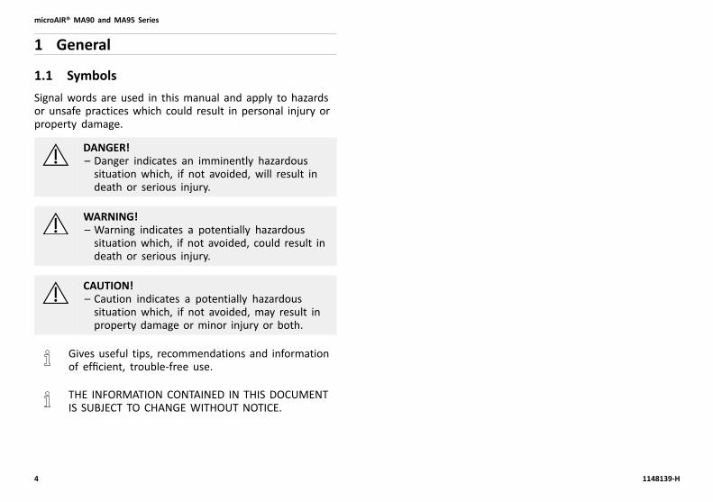
1.1 SymbolsSignal words are used in this manual and apply to hazardsor unsafe practices which could result in personal injury orproperty damage.
DANGER!– Danger indicates an imminently hazardoussituation which, if not avoided, will result indeath or serious injury.
WARNING!– Warning indicates a potentially hazardoussituation which, if not avoided, could result indeath or serious injury.
CAUTION!– Caution indicates a potentially hazardoussituation which, if not avoided, may result inproperty damage or minor injury or both.
Gives useful tips, recommendations and informationof efficient, trouble-free use.
THE INFORMATION CONTAINED IN THIS DOCUMENTIS SUBJECT TO CHANGE WITHOUT NOTICE.
4 1148139-H

Safety
2 Safety
2.1 General Guidelines
DANGER!Risk of Death, Injury or DamageImproper use of this product may cause injuryor damage.– If you are unable to understand the warnings,cautions or instructions, contact a healthcareprofessional, dealer or technical personnelbefore attempting to use this equipment.
– Do not use this product or any availableoptional equipment without first completelyreading and understanding these instructionsand any additional instructional material suchas user manuals, service manuals or instructionsheets supplied with this product or optionalequipment.
DANGER!Risk of Death, Injury or DamageTo avoid risk of death, injury or damage from useof malfunctioning or damaged product:– DO NOT use damaged or malfunctioningproduct.
– Stop using the product immediately if theproduct becomes damaged or malfunctions.
– Contact a qualified technician or Invacare forrepair if product is damaged or malfunctioning.
DANGER!Risk of Death, Injury or DamageLighted cigarettes can cause a fire or other relatedhazards resulting in death, injury or damage.– DO NOT smoke while using this product.– DO NOT allow others to smoke near thisproduct.
DANGER!Risk of Death, Injury or DamageParts and accessories designed by othermanufacturers have NOT been tested by Invacare.Use of NON-Invacare parts and accessories mayresult in injury or death.– Use ONLY Invacare rails, mattresses, bedextenders, other accessories and parts withInvacare products.
DANGER!Risk of Death, Injury or DamageConditions such as restlessness, mentaldeterioration and dementia or seizure disorders(uncontrolled body movement), sleepingproblems, and incontinence can significantlyimpact a patient's risk of entrapment. Pediatricpatients or patients with small body size may alsohave an increased risk of entrapment.– Monitor patients with these conditionsfrequently.
– Place mattress deck in the flat position whenleft unattended.
1148139-H 5
microAIR® MA90 and MA95 Series
DANGER!Risk Of Death, Injury Or DamageTo avoid risk of injury due to pressure ulcers:– Skin condition should be checked frequentlyafter the installation and during use of thisproduct.
– Proper product evaluation becomes moreimportant as the needs of the individualbecome more complex. Work with yourtherapist, physician and equipment supplier toassure that a product matches your individualneeds.
– Consult your therapist or physician if you haveany questions regarding individual limitationsand needs.
DANGER!Risk Of Death Or InjuryTo avoid risk of death or injury from choking oringestion of small parts or materials:– Closely supervise children, individuals withmental disabilities or pets.
DANGER!Risk Of Death Or InjuryTo avoid risk of death or injury due to misuse ormodification:– DO NOT use this product in any way other thandescribed in this manual.
– DO NOT modify the product or any componentsof the product.
Contraindications
WARNING!Risk Of Injury Or DeathTo avoid injury or death from misuse of product:– Always consult the patient’s physician beforeusing the MicroAir mattress system.
6 1148139-H

Safety
Electrical
DANGER!Risk Of Shock InjuryTo avoid injury due to shock hazard, this productis equipped with three prong (grounding) plugs.It is the responsibility and obligation of thecustomer to contact a qualified electrician andhave the two prong receptacle replaced witha properly grounded three prong receptaclethat is in accordance with the National ElectricCode where a two prong wall receptacle isencountered:– Use only a Underwriter Laboratory (UL)approved three prong extension cord havingthe same or higher electrical rating as theproduct being connected if you must use anextension cord.
– DO NOT use three prong to two prong adapters.
DANGER!Risk of Death, Injury Or DamageTo avoid death, injury or damage due to electricalshock:– DO NOT disassemble controls or othercomponents.
– DO NOT insert items into any openings of thecontrol unit.
– Contact qualified technician or Invacare forrepair.
DANGER!Risk of Death, Injury Or DamageTo reduce the risk of electrical shock:– Always unplug the bed from the electricaloutlet before any maintenance.
– Ensure all power cords are routed and securedproperly.
– Inspect power cords and outlets for damage.Stop using the product immediately if thecord or outlet is damaged. Contact qualifiedtechnician or Invacare for service.
WARNING!Risk Of Injury Or DamageTo avoid electrical damage, product damage,shock and/or personal injury:– Keep all bed components and accessories aminimum of 12 inches (30,5 cm) away fromhot or heated surfaces.
WARNING!Risk Of Injury Or DamageTo avoid electrical damage, product damage,shock and/or personal injury:– Unplug the product if liquid is spilled in oraround the product.
– Clean up the spill and allow the product andsurrounding area to dry thoroughly.
1148139-H 7

microAIR® MA90 and MA95 Series
WARNING!Risk Of Injury Or DamageTo avoid personal injury or damage:– Check for leakage from electrical componentssuch as batteries and circuit boards.
– Remove product from service and contactdealer or Invacare for repair if leakage is found.
Entrapment
DANGER!Risk of Death, Injury or DamageProper patient assessment and monitoring, andproper maintenance and use of equipment isrequired to reduce the risk of entrapment.Variations in bed rail dimensions, and mattressthickness, size or density could increase the riskof entrapment.– Visit the FDA website at http://www.fda.gov tolearn about the risks of entrapment.
Refer to the Bed Rail Entrapment Risk NotificationGuide at www.invacare.com for additional safetyinformation.
WARNING!Risk Of Death, Injury Or DamageTo avoid risk of death, injury or damage fromproduct misuse or entrapment:– Read and understand the User Manual prior tousing this product. User manuals are availableat www.invacare.com or your dealer.
– Refer to user manuals for beds and rails foradditional product safety information.
– Proper patient assessment and monitoring isrequired. Work with therapist, physician andother medical staff to perform assessment andpatient monitoring.
– Variations in bed rail dimensions, mattressthickness, size or density could increase riskof entrapment.
– The Invacare mattress MUST fit firmly againstthe bed frame AND bed side rails to preventpatient entrapment. Follow the manufacturer’sproduct instructions.
– After any adjustments, repair or service andbefore use, make sure all attaching hardwareis tightened securely.
8 1148139-H

Safety
WARNING!Risk of Death or InjuryTo avoid risk of death or injury from entrapmentor falling:– Invacare suggests rails be in the raised or guardposition whenever a patient is on the bed.
– Health care professionals assigned to eachcase should make the final determinationwhether side or assist rails are warrantedafter assessing patient risks of entrapment andfalls in accordance with state patient restraintlegislation or facility interpretation of suchlegislation.
Fire Hazard
DANGER!Risk Of Product Damage, Injury, Or DeathTo avoid damage, injury, or death from explosion:– Do not use with flammable anesthetics.
DANGER!Risk Of Product Damage, Injury, Or DeathTo avoid damage, injury, or death from fire:– Only use nasal mask or half bed tent type withoxygen administering equipment.
– Do not allow oxygen tent to extend belowmattress support level.
Installation
WARNING!Risk Of Injury Or DamageTo avoid serious injury or damage from tripping,entanglement and/or pinched, or severed cords:– Ensure that all cord(s) are routed and securedproperly.
– Keep all moving parts, including the mainframe, mattress deck, and all drive shafts, freeof obstruction (i.e. blankets/sheets, tubing,wiring, cords, etc.) during operation of theproduct.
1148139-H 9

microAIR® MA90 and MA95 Series
WARNING!Risk Of Injury Or DamageTo avoid serious injury or damage from airbornepollutants and/or fumes and for optimalperformance:– Locate and position the product in a wellventilated space so that the air intake andexhaust are not blocked or obstructed.
– Place product in well ventilated area.– Avoid use in presence of pollutants, smoke orfumes, flammable anesthetics, cleaning agentsor chemical vapors.
– Keep openings free from lint, hair or similarforeign items.
– Keep product at least 12 inches (30,5 cm) awayfrom walls, draperies and furniture.
WARNING!Risk Of DamageTo avoid damage to the mattress:– DO NOT strap the mattress to the bed frame atthe end and foot ends.
– Secure mattress straps to the bed deck at thehead and foot ends and to the bed frame atthe center of the bed.
Repair and Service
DANGER!Risk of Death, Injury, or DamageTo avoid death, injury or damage due to impropermaintenance or inspection. Always maintainand inspect equipment per the instructions inthis manual. Contact a qualified technician orInvacare if any of the following issues are present:– Loose or missing parts such as end caps,knobs, bolts, screws etc., should be securedor replaced.
– Sharp edges or surfaces should be correctedor replaced.
– Parts showing excessive wear should bereplaced.
– Warped or otherwise damaged parts should bereplaced immediately.
WARNING!Risk Of Injury Or DamageTo avoid injury or damage due to collapse ormissing hardware:– After any adjustments, repair or service andbefore use, make sure all attaching hardwareis tightened securely.
10 1148139-H

Overview
3 Overview
3.1 Label LocationLabels are subject to change without notice.This label is on the back of the unit and also contains the serial number.
WARNING!Risk of Injury, Damage or DeathMissing or damaged labels may contribute to injury, damage or death.– Ensure labels are present and legible.
1148139-H 11

microAIR® MA90 and MA95 Series
3.2 Technical DataMA90Z power unit is also used on MA90ZB42 andMA90ZB48 systems.
MA95Z power unit is also used on MA95ZB42 andMA95ZB48 systems.
Electrical Specifications
MA90Z MA95Z
Input Voltage AC: 110 V
Input Frequency: 60 Hz
Current: 1 A 2 A
Maximum PowerConsumption:
30 ± 10 W 150 ± 10 W
Circuit Protection: Dual fused,
250 V,
1 A slow blowfuses
Dual fused,
250 V,
5 A fast blowfuses
Mode OfOperation:
Continuous
Environmental Specifications
Operating Conditions MA90Z/MA95Z
Ambient Temperature: 50°–95° F
Relative Humidity: 30%–75% Non-Condensing
Atmospheric Pressure: 70–106 kPa
Storage And ShippingConditions
Ambient Temperature: -40°–158° F
Relative Humidity: 10%–100%
Atmospheric Pressure: 50–106 kPa
12 1148139-H

Overview
Performance Specifications
MA90Z MA95Z
Mattress Weight Capacity
Standard — 36inch:
350 lbs
Bariatric — 42Inch:
650 lbs
Bariatric — 48Inch:
1000 lbs
Pressure Zone
Maximum Flow: 50 ± 15 LPM 1275 ± 100 LPM
MaximumPressure:
35 ± 5 mmHg
Maximum FlowTimer:
30 minutes 15 minutes
Support SurfaceInflation Time:
5–10 minutes 25–60 seconds
Patient Comfort Control Pressures:
Soft Pressure: 8 ± 4 mmHg
Firm Pressure: 32 ± 4 mmHg
Rotation Time: 10, 20, 30, 60minutes
5 minutes–4 hrs
Rotation Angle: 0–30° ± 5° 0–40° ± 5°
Patient Contact: Control unit and mattress haveLatex-Free components
1148139-H 13
microAIR® MA90 and MA95 Series
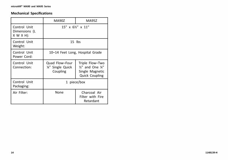
Mechanical Specifications
MA90Z MA95Z
Control UnitDimensions (LX W X H):
15” x 6½” x 11”
Control UnitWeight:
15 lbs
Control UnitPower Cord:
10–14 Feet Long, Hospital Grade
Control UnitConnection:
Quad Flow–Four¼” Single Quick
Coupling
Triple Flow–Two½” and One ¼”Single MagneticQuick Coupling
Control UnitPackaging:
1 piece/box
Air Filter: None Charcoal AirFilter with Fire
Retardant
14 1148139-H

Setup
4 Setup
4.1 Unpacking1. Remove any loose packing from the carton.2. Carefully remove all components from the carton.3. Inspect all components for damage. Contact dealer
or Invacare if components are damaged. DO NOT useproduct.
DANGER!Risk of Injury or DamageContinued use of the product with damaged partscould lead to the product malfunctioning, causinginjury to the user and/or caregiver.– Check ALL product components and cartonfor damage, and test components before use.In case of damage or if the product is notworking properly, contact a qualified technicianor Invacare for repair.
WARNING!Risk of Injury or DamageTo avoid damage or personal injury from strain ormishandling of product:– Use proper lifting techniques (lift with yourlegs) when handling the product or accessories.
– Obtain assistance when necessary to lift orhandle product safely.
WARNING!Risk of Injury or DamageTo avoid damage or personal injury from misuse:– DO NOT plug the power cord into a powersource until assembly is complete.
– DO NOT attempt to operate product controlsprior to completion of assembly.
1148139-H 15

microAIR® MA90 and MA95 Series
4.2 Mattress Replacement System Installation
CAUTION!Risk Of DamageTo avoid damage to the mattress:– Do not strap the mattress to the bed frame atthe head and foot ends.
– Secure all mattress straps.– Secure the straps to the bed deck at the headand foot ends and to the frame at the centerof the bed.
The powered mattress comes with ten nylon bucklestraps. 1. Remove the original foam mattress from the bed.
2. If necessary, lower the side rails to facilitate installationof the mattress.
3. Unroll the powered mattress D and place it on the bedframe.
Ensure that the hose E is towards the foot endB of the bed.
4. Use the buckle straps F to secure the powered mattressto the bed deck in the following locations:• Head End—Head End Bed Deck A• Foot End—Foot End Bed Deck B• Center—Center of the Bed Frame C
16 1148139-H

Setup
4.3 Installing the Side RailsRefer to the Bed Rail Entrapment Risk NotificationGuide at www.invacare.com for additional safetyinformation.
Refer to the instructions provided with the side railsfor the installation procedure.
4.4 Installing the Power Unit
1. Pull out the bed hook A on the back of the control unit.2. Place the control unit on the footboard.
If the bed does not have a footboard, place thecontrol unit on a flat surface, leaving room forthe hose to hang down.
4.5 Connecting the Hose
CAUTION!Risk Of Injury Or DamageTo prevent falling, stepping on the hose, orcausing other injuries or damage:– Ensure that the hose connecting the controlunit to the mattress is routed such that itcannot be stepped on, kinked, squeezed orotherwise damaged.
1148139-H 17

microAIR® MA90 and MA95 Series
1. Locate the hose at the foot end of the mattress.
2. Locate control unit connectors on right side of controlunit B.
3. Perform one of the following:
• MA90Z Power Unit—Perform the following:
a. Squeeze and hold the tabs C on the hoseconnector D.
b. Push the hose connectors onto the controlconnector until an audible click is heard.
The audible click indicates that hoseconnector(s) are properly engaged withcontrol connectors.
18 1148139-H
Setup
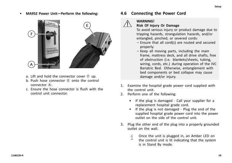
• MA95Z Power Unit—Perform the following:
a. Lift and hold the connector cover F up.b. Push hose connector E onto the control
connector A.c. Ensure the hose connector is flush with the
control unit connector.
4.6 Connecting the Power Cord
WARNING!Risk Of Injury Or DamageTo avoid serious injury or product damage due totripping hazards, strangulation hazards, and/orentangled, pinched, or severed cords:– Ensure that all cord(s) are routed and securedproperly.
– Keep all moving parts, including the mainframe, mattress deck, and all drive shafts, freeof obstruction (i.e. blankets/sheets, tubing,wiring, cords, etc.) during operation of the IVCBariatric Bed. Otherwise, entanglement withbed components or bed collapse may causedamage and/or injury.
1. Examine the hospital grade power cord supplied withthe control unit.
2. Perform one of the following:
• If the plug is damaged - Call your supplier for areplacement hospital grade cord.
• If the plug is not damaged - Plug the end of thesupplied hospital grade power cord into the poweroutlet on the side of the control unit.
3. Plug the other end of the plug into a properly groundedoutlet on the wall.
Once the unit is plugged in, an Amber LED onthe control unit is lit indicating that the systemis in Stand By mode.
1148139-H 19

microAIR® MA90 and MA95 Series
4.7 EMC InformationUse of portable and mobile radio frequencyequipment can effect medical electrical equipment.
CAUTION!Risk Of DamageElectronic equipment may be influenced by RadioFrequency Interference (RFI).– Caution should be exercised with regard to theuse of portable communications equipment inthe area around such equipment.
– If RFI causes erratic behavior, unplug theproduct immediately. Leave unplugged whiletransmission is in progress.
Medical Electrical Equipment needs to be installed and usedaccording to the EMC information in this manual.
This equipment has been tested and found to complywith EMC limits specified by IEC/EN 60601–1–2 for TypeBF equipment. These limits are determined to providereasonable protection against electromagnetic interference ina typical home healthcare environment. This product is notintended for use in a professional healthcare environment.
Portable and mobile RF communications equipment caneffect the operation of this product.
Other devices may experience interference from even thelow levels of electromagnetic emissions permitted by theabove standard. To determine if the emissions from productare causing the interference, turn the product off. If theinterference with the other device operation stops, thenthe product is causing the interference. In such rare cases,interference may be reduced or corrected by one of thefollowing measures:
• Reposition, relocate, or increase the separation betweenthe devices.
• Connect either line powered device to a differentelectrical power circuit.
Contact Invacare for any additional EMC information or EMCtables for the device environment.
20 1148139-H

Usage
5 Usage
5.1 Using the Front Panel
DETAIL “A” — MA90Z Power Unit Front Panel
DETAIL “B” — MA95Z Power Unit Front Panel
1148139-H 21
microAIR® MA90 and MA95 Series
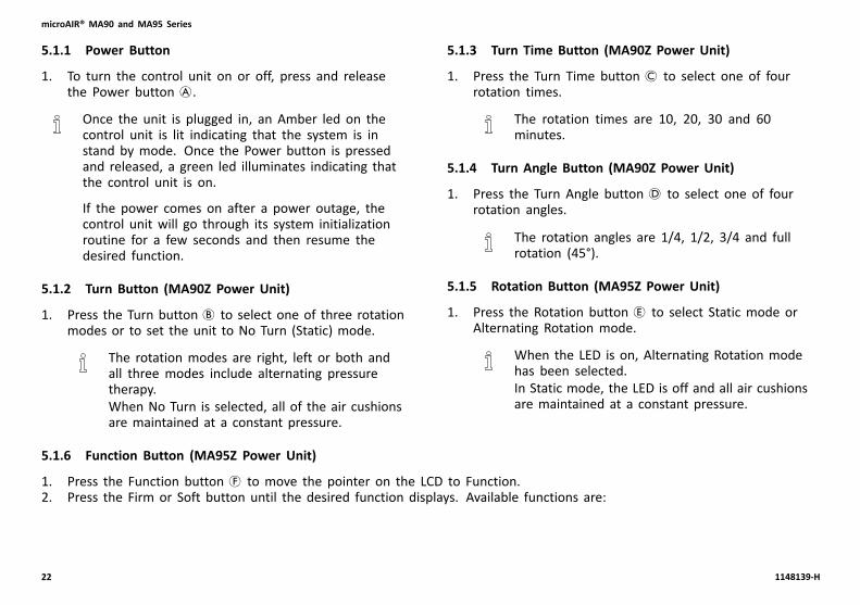
5.1.1 Power Button
1. To turn the control unit on or off, press and releasethe Power button A.
Once the unit is plugged in, an Amber led on thecontrol unit is lit indicating that the system is instand by mode. Once the Power button is pressedand released, a green led illuminates indicating thatthe control unit is on.
If the power comes on after a power outage, thecontrol unit will go through its system initializationroutine for a few seconds and then resume thedesired function.
5.1.2 Turn Button (MA90Z Power Unit)
1. Press the Turn button B to select one of three rotationmodes or to set the unit to No Turn (Static) mode.
The rotation modes are right, left or both andall three modes include alternating pressuretherapy.When No Turn is selected, all of the air cushionsare maintained at a constant pressure.
5.1.3 Turn Time Button (MA90Z Power Unit)
1. Press the Turn Time button C to select one of fourrotation times.
The rotation times are 10, 20, 30 and 60minutes.
5.1.4 Turn Angle Button (MA90Z Power Unit)
1. Press the Turn Angle button D to select one of fourrotation angles.
The rotation angles are 1/4, 1/2, 3/4 and fullrotation (45°).
5.1.5 Rotation Button (MA95Z Power Unit)
1. Press the Rotation button E to select Static mode orAlternating Rotation mode.
When the LED is on, Alternating Rotation modehas been selected.In Static mode, the LED is off and all air cushionsare maintained at a constant pressure.
5.1.6 Function Button (MA95Z Power Unit)
1. Press the Function button F to move the pointer on the LCD to Function.2. Press the Firm or Soft button until the desired function displays. Available functions are:
22 1148139-H

Usage
Function Description
Left Rotation to the Left side. The time indicates the rotationduration.
Center Rotation to Center. The time indicates the rotation duration.
Right Rotation to the Right side. The time indicates the rotationduration.
Static Static mode. All air cushions maintain constant pressure.
Pulse Set 10 minute pulse time cycle. All of the air cushions in themattress will remain static at the current pressure settings for10 minutes, then the pressure in the mattress will decreaseby 20% for five seconds. After five seconds, the mattresswill once again inflate to the set pressure settings for 10minutes, then deflate by 20% for five seconds, and the cycleis repeated.
Multi-Pulse The cycle duration can be set from 1 to 99 minutes. In thissetting, the mattress will remain static at the current pressuresettings for the time selected. Then, every two minutes, forthe time selected, the pressure in the mattress will decreaseby 20% for five seconds. This pulse cycle repeats itself for theselected time. (i.e...if 10 minutes is selected, the mattresswill initially remain static for 10 minutes. Then, every twominutes, the pressure in the mattress will decrease by 20%for five seconds. the mattress will then inflate back to the setpressure setting and remain static for the time selected andthe cycle is repeated.)
Fowler, Upright Fowler Mode. The pressure will increase to prevent thepatient from bottoming out.
1148139-H 23

microAIR® MA90 and MA95 Series
3. Use the Function button to move the pointer to the times or attributes available for the selected function.4. Use the Firmer or Softer buttons to change the times or attributes.
5.1.7 Hold Button (MA95Z Power Unit)
1. Press the Hold button G to pause the mattress inthe current position. The mattress will remain in thisposition until the Hold button is pressed again.
5.1.8 Firm/Soft Buttons
1. Select comfort pressure settings by pressing Firm H orSoft I buttons.
• Soft Button—Pressing this button reduces thepressure in the mattress.
• Firm Button—Pressing this button increases thepressure in the mattress.
The patient comfort pressure ranges from Soft(8 ±4 mmHg) to Firm (32 ±4 mmHg). TheComfort Control LED displays the patient comfortpressure levels and provides a guide to thecaregiver to set approximate comfort pressurelevel depending on the patient weight. If thepatient’s weight to height ratio is above average,increase the pressure setting by approximately20%. MA90Z models display levels from 0 to9 and MA95Z models display the mmHg from8 to 32.
5.1.9 Mode Button (MA90Z Power Unit)
Press the Mode button J to select the Max Inflate Modeor the Low Air Loss mode.
Low Air Loss Mode
In this mode, the mattress goes into on-demand low airloss relief mode.
Max Inflate Mode
In this mode, the mattress inflates rapidly to maximumfirmness (pressurized to 35 ±5 mmHg). A series of beepssound every three minutes as a reminder that the MaxInflate mode is active. After 30 minutes, the Max Inflatemode deactivates and the control unit defaults to theprevious setting.
• It takes 5–10 minutes for the MA90Z mattress to inflatefully (inflation time depends on size of mattress).
• Max Inflate mode can be manually disengaged bypressing the Max Inflate button. This will deactivatethe Max Inflate LED.
• It is recommended that Max Inflate setting be usedduring patient ingress/egress, patient wound care,patient turning or patient cleaning.
5.1.10 Max Inflate Button (MA95Z Power Unit)
Press the Max Inflate button K to select the max inflatemode and inflate the mattress rapidly to maximum firmness(pressurized to 35 ± 5 mmHg). A series of beeps sound everythree minutes as a reminder that the Max Inflate mode isactive. After 30 minutes, the Max Inflate mode deactivatesand the control unit defaults to the previous setting.
• It takes 25–60 seconds for the MA95Z mattress toinflate fully (inflation time depends on size of mattress).
24 1148139-H

Usage
• Select a different setting to exit Max Inflate mode, orpress the Max Inflate button again. This will deactivatethe Max Inflate LED.
• It is recommended that Max Inflate setting be usedduring patient ingress/egress, patient wound care,patient turning or patient cleaning.
5.1.11 Automatic Wireless Fowler
Manual Operation of the Fowler
1. Press the Function button F to move the pointer onthe LCD to Function.
2. Use the Firm and Soft buttons until Fowler displays.
When this mode is activated, the control unitincreases the pressure in the mattress to preventthe patient from bottoming out.
Automatic Wireless Mode
When the bed articulates to 45°, the transmitter in the headof the mattress signals the control unit to add 25% more airinto the mattress to prevent the patient from bottoming out.
Programming the Automatic Wireless Fowler Transmitter
1. Ensure the mattress is in a flat position.2. Make sure fowler transmitter is in the mattress cover
pocket in the orientation indicated on the transmitter.
Mattress cover pocket is on the inside of themattress cover on the bottom left side at thehead end.
3. Ensure the control unit is plugged in, and the LCDdisplays STAND BY.
4. Perform one of the following:
• MA90Z Power Unit - Perform the following steps:
a. Press and hold the Turn Angle and Max Inflatebuttons.
The Fowler LED is lit and L displays inthe LCD Display.
b. Raise the bed to 45°.
The control unit will beep and will returnto Standby.
c. Perform one of the following:
– Cancel—Press the Turn Angle button to exitFowler Transmitter Setup without linking toa transmitter.
– Save—Wait 60 seconds without pressing a key.
• MA95Z Power Unit—Perform the following steps:
a. Press and hold the Hold and Max Inflate buttons.b. AUTO FOWLER LEARN MODE will display.c. PLACE BED IN FLAT POSITION will display.d. CONTINUE -> SELECT will display.e. Press the Function button.f. PLACE BED IN FOWLER/UPRIGHT POSITION will
display.g. TRANSMITTER DETECTED will display.h. The control unit will beep.i. STAND BY will display.
1148139-H 25

microAIR® MA90 and MA95 Series
Fowler Transmitter Battery Replacement (if equipped)
The transmitter has an LED light to indicate the status of thebattery. Green indicates good voltage and red indicates lowor no voltage. Replace fowler if red indicator is present.Batteries may be replaced on fowlers where batteries areaccessible. Sealed fowlers will need to be replaced as awhole part.
• Battery must be 3.6V lithium AA battery.• When battery is first inserted the LED light will flash
four times to indicate a 45° fowler.• Replace transmitter in mattress cover pocket in the
orientation indicated on the transmitter.• Dispose of old battery according to local laws and
statutes.
5.1.12 Lock/Alarm Silence Button
1. Press the Lock/Alarm Silence button L to select one ofthe following modes:
• Lock Mode - Pressing this button locks out allcontrol unit functions, including the On button, toprevent any tampering with the settings. Press thebutton for approximately 3-5 seconds for the LockLED to activate.
The Lock LED illuminates when in this mode.
• Alarm Silence mode - Pressing this button silencesthe alarm that sounds in the event of power failureor when the hose is disconnected from the controlunit
The Alarm LED illuminates when in thismode.
5.1.13 Power Fail LED
In the event of power outage, an alarm sounds and thePower Fail LED M flashes Amber. The control unit hasinternal memory and retains the previous settings duringthe power outage.
During a power outage, the MA90Z, MA90ZB42 andMA90ZB48 mattress retains the air as long as themattress is connected to the control unit.
26 1148139-H

Usage
Periodically test alarm by unplugging the powercord from the wall outlet while unit is on. Seetroubleshooting section of this manual if alarm failsto sound.
5.1.14 Low Pressure LED
In the event that the mattress hose disconnects, an alarmsounds and Low Pressure LED N flashes Amber. Once thelow pressure problem is fixed, the control unit resumesoperation in the previously set mode.
Periodically test alarm by disconnecting the mattresshose. It may take up to 15 minutes for unit to loseenough air for alarm to sound. See troubleshootingsection of this manual if alarm fails to sound.
5.1.15 Displaying the Total Run Time(MA95Z Power Unit)
Every time the control unit is plugged in, the LCD screendisplays the Run Time in hours and minutes. For example,2,584 hours and 25 minutes displays as 002584 Hours000025 Minutes.
To display the Run Time during use:
1. Ensure the control unit is plugged in and the StandbyLED is On.
2. Press and hold the Soft and Firm Buttons at the sametime.
3. The LCD screen displays the Run Time as describedabove.
5.2 Powering Up the SystemFor this procedure, refer to 5.1 Using the FrontPanel, page 21.
1. Turn on the power to the system by pressing the Powerbutton on the control unit.
Once the button is released, a green ledilluminates when the unit is on.
1148139-H 27

microAIR® MA90 and MA95 Series
5.3 Placing Patient on the Mattress1. Press the Mode button or Max Inflate button to turn on
the control unit to maximum flow.
In this mode, the Max Inflate Led lights up.
2. After the mattress is fully inflated, place the patienton the bed.
3. Ensure that the patient’s feet are towards the foot endof the mattress (the end with the hose).
4. Center the patient on the bed from side-to-side andhead-to-foot.
Special positioning may be required withcontracted patients to provide comfortablepositions.
5. After placing the patient, make certain no objects willfall under the patient, such as feeding tubes, IV's etc.
6. Wait five minutes for the mattress pressure to stabilize.7. Set the comfort pressure to the desired comfort level.8. Wait five minutes for the mattress pressure to stabilize.
9. Verify that the patient has not bottomed out byperforming the following steps:
a. Ensure that the patient is lying flat on his/her back inthe middle of the mattress.
b. Place four fingers between the air cushions directlyunderneath the sacral region of the patient’s body.
c. Ensure that there is 3 to 4-finger width clearancebetween the bottom of the patient and the bedframe.
d. Adjust the comfort setting, if needed.e. Wait five minutes for the mattress pressure to
stabilize.f. Repeat Steps A-E until patient has not bottomed out
and patient comfort is achieved.
10. If the patient feels that the bed is too soft/hard, pressthe Soft or Firm button to adjust the comfort settings.
11. Use a regular pillow to help support and stabilize thepatient's head.
28 1148139-H

Usage
5.4 Transferring Patient From/To a Gurney
WARNING!Risk Of InjuryTo avoid injury from falling:– ALWAYS engage the wheel locks of the bedand the wheel locks of the gurney beforetransferring the patient between the bed andthe gurney.
1. Engage the wheel locks of the bed. Refer to the usermanual provided with the bed.
2. Engage the wheel locks of the gurney. Refer to the usermanual provided with the gurney.
3. Press the Max Inflate button to achieve maximummattress pressure.
4. Raise or lower the bed to match the gurney height.Refer to the user manual provided with the bed.
5. When the mattress has reached maximum firmness,perform one of the following:
• Bed to Gurney Transfer - Slide the patient ontothe gurney.
• Gurney to Bed Transfer - Slide the patient ontothe bed.
5.5 Transferring Patient From/To a Wheelchair
WARNING!Risk Of InjuryTo avoid injury from falling:– ALWAYS engage the wheel locks of the bedand the wheel locks of the gurney beforetransferring the patient between the bed andthe wheelchair.
1. Engage the wheel locks of the bed. Refer to the usermanual provided with the bed.
2. Engage the wheel locks of the wheelchair, if applicable.Refer to the user manual provided with the wheelchair.
3. Press the Max Inflate button to achieve maximummattress pressure.
4. Raise or lower the bed to match the wheelchair height.Refer to the user manual provided with the bed.
5. When the mattress has reached maximum firmness,perform one of the following:
• Bed to Wheelchair Transfer - Slide the patient ontothe wheelchair.
• Wheelchair to Bed Transfer - Slide the patient ontothe bed.
1148139-H 29

microAIR® MA90 and MA95 Series
5.6 Preparing for CPR ProcedureMA90Z
1. Press and hold the tabs A on the hose connector B .2. Pull the hose connector B from the control unit
connectors.
3. Disconnect the red CPR connector located on the hoseF.
30 1148139-H

Usage
MA95Z 1. Lift the connector cover C.
2. Pull the hose connector E from the control unitconnectors.
If the hose connector is difficult to release, pullthe hose connector down and then away.
DANGER!Risk of Death or InjuryTo reduce the risk of death or injury:– Move patient to appropriate surface to performCPR if unable to deflate mattress.
1148139-H 31

microAIR® MA90 and MA95 Series
6 Maintenance
6.1 Service Life
WARNING!Risk of Injury or DamageUse of the product beyond this time period maycause product damage and injury.– This product has an expected lifetime of one(1) year when used in accordance with safetyinstructions, maintenance intervals and correctuse stated in this manual.
– Perform all maintenance according to therecommended schedule in this manual.
The effective product lifetime can vary according tothe frequency and intensity of use.
6.2 Cleaning the System
WARNING!RISK OF INJURY OR DAMAGETo avoid injury or damage from sharp objects:– Before cleaning or disassembling the MA90and MA95Z series, check the underside ofthe mattress folds for sharp objects such asscissors, needles, etc.
– Remove and discard sharp objects beforeproceeding with cleaning or disassembly.
WARNING!RISK OF INJURY OR DAMAGETo avoid infectious exposure:– Do not clean the bed when the patient isoccupying the bed.
– Inspect all equipment. Properly clean orremove any item soiled with the patient’sblood or other body fluids.
– Treat all soiled bedding as if it is contaminatedwith pathogenic microorganisms.
Follow standard institutional wipe down and infectioncontrol procedures.
Follow the instructions provided by the cleaningsolution manufacturer for proper use and dilution.
1. Remove the bedding.2. If necessary, inflate the mattress.3. Ensure that the control unit is off.4. Unplug the power cord from the wall outlet.5. Ensure that the underside of the mattress is clear of
all sharp objects.6. Examine the surface of the control unit and mattress
assembly components for visible blood or body fluids.
32 1148139-H
Maintenance
7. Perform one of the following:
• If blood is present, decontaminate the product.
a. Remove all visible soil with disposable papertowels.
b. Scrub the area with freshly prepared effectivephenolic detergent disinfectant solution.
• If blood is not present, remove any soil from thecover with paper towels.
If soiled, the cover should be removed, cleanedand decontaminated.
8. To avoid damage, the following steps are recommendedfor cleaning the mattress cover:
a. To disinfect the cover:i. Using a clean sponge or paper towel, wipe
down the cover with a dilute detergent solutionof quaternary cleaner disinfectant or othergermicidal detergent solution.
ii. Let the cover completely dry.b. To launder the cover:
i. Using a clean sponge or paper towel, wipedown the cover with a dilute detergent solutionof quaternary cleaner disinfectant or othergermicidal detergent solution.
ii. Remove the cover and launder it using thefollowing method:
CAUTION!Risk Of DamageTo avoid contaminating bedding, damagingfabric or damaging washing machine:– Wash hands before working with cleanbedding.
– Do not overload the machine.– Do not use chlorine bleach.
CAUTION!Risk Of DamageTo avoid damage to product:– DO NOT use cleaning agents containingphenols, alcohols, bleaches or otherabrasive materials.
– DO NOT use granules.– 1% Chlorine Solution used on a regularbasis can diminish the life of the productif not rinsed and dried properly.
– Keep product clear of open heat sources.
i. Place the cover in a washing machine.ii. Wash with warm water (below 120°F).iii. Add detergent and disinfectant according to the
manufacturer’s instructions.iv. Remove excess water.v. Set the dryer to the lowest setting (below 120°F).vi. Dry the cover until it is completely dry.
1148139-H 33

microAIR® MA90 and MA95 Series
9. Perform the following steps to clean the control unitand hose fittings:
a. Wipe all controls, chassis and hose fittings with aquaternary disinfectant solution.
b. Using a nylon brush, gently clean all crevices as theycan harbor microorganisms.
c. Air dry all treated surfaces.
10. Perform the following steps to clean the mattresscomponents (air cushions, mattress base, etc.):
a. Using a clean sponge or paper towel, wipe down themattress components with a dilute detergent solutionof quaternary cleaner disinfectant or other germicidaldetergent solution.
b. Wipe the mattress components with a clean drycloth.
11. Test alarm function for power fail and low pressure.
6.3 DisposalFollow local governing ordinances and recycling plansregarding disposal of the product or components normallyused in operation. The product does not generate wasteor residue in operation. Any accessories not part of theproduct MUST be handled in accordance with the individualproduct marking for disposal.
This product has been supplied from an environmentallyaware manufacturer that complies with the Waste Electricaland Electronic Equipment (WEEE) Directive 2012/19/EC.
This product may contain substances that could be harmfulto the environment if disposed of in places (landfills) thatare not appropriate according to legislation.
Please be environmentally responsible and recycle thisproduct through your recycling facility at its end of life.
The disposal and recycling of used devices and packagingmust comply with the applicable legal regulations.
6.4 Storing the System1. Ensure that the control unit is off and disconnect the
power cord from the wall outlet.2. Clean the system. Refer to 6.2 Cleaning the System,
page 32.3. Disconnect the air hose connector from the control unit
and allow air to vent from the mattress.4. Gently roll up the mattress with minimal handling and
agitation.5. Ensure the cover surface is inside the roll.6. Store the unit, keeping the mattress with the control
unit.34 1148139-H
Maintenance
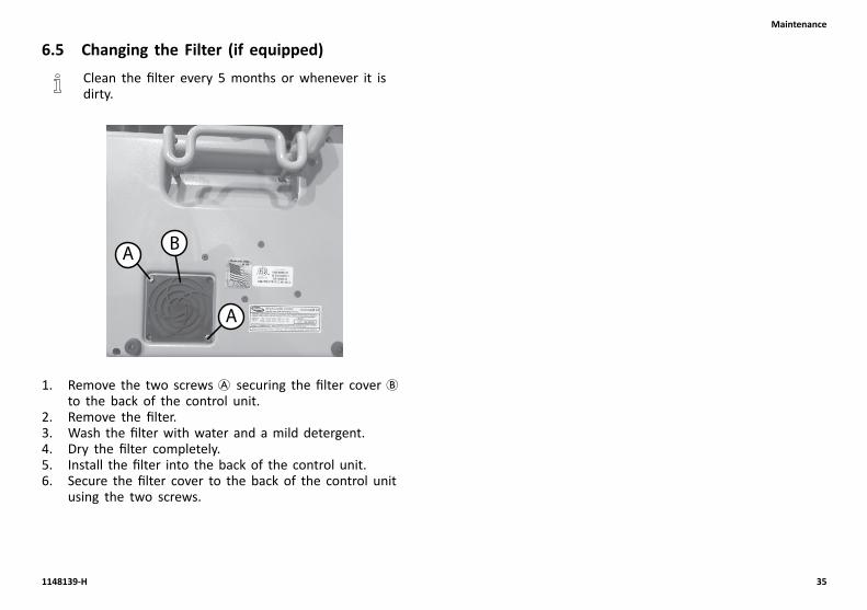
6.5 Changing the Filter (if equipped)Clean the filter every 5 months or whenever it isdirty.
A
A
B
1. Remove the two screws A securing the filter cover Bto the back of the control unit.
2. Remove the filter.3. Wash the filter with water and a mild detergent.4. Dry the filter completely.5. Install the filter into the back of the control unit.6. Secure the filter cover to the back of the control unit
using the two screws.
1148139-H 35

microAIR® MA90 and MA95 Series
7 Troubleshooting
7.1 Troubleshooting
Problem Cause Solution
Mattress hose disconnected Connect hose connectors and lock themin place
Air hose kinked or split Unkink hose or replace split hose
Major leak in the air cushions or overlaypad
Replace leaking air cushions or overlaypad
Kinked or split manifold Unkink manifold or replace split manifold
Has power and fuse is good, control unitdoes not come on
Send unit back for repair
Not alternating, solenoid or valvemalfunction
Send control unit back to factory forrepair
Mattress not inflating
Not alternating properly
No air, pump or blower malfunction. Send unit for repair
Control unit off Check power source and turn on unit
Power cord disconnected Connect power cord to the power source
No power in the power source Check power source has power powerand turn it On
Power outage Wait till the power source has power
No power
Blown fuse Replace blown fuse with an equivalentfuse
36 1148139-H
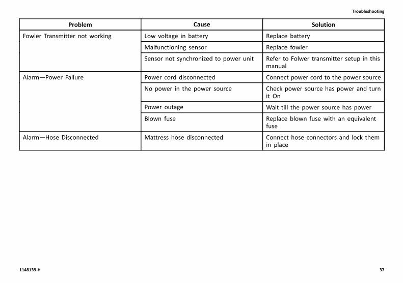
Troubleshooting
Problem Cause Solution
Low voltage in battery Replace battery
Malfunctioning sensor Replace fowler
Fowler Transmitter not working
Sensor not synchronized to power unit Refer to Folwer transmitter setup in thismanual
Power cord disconnected Connect power cord to the power source
No power in the power source Check power source has power and turnit On
Power outage Wait till the power source has power
Alarm—Power Failure
Blown fuse Replace blown fuse with an equivalentfuse
Alarm—Hose Disconnected Mattress hose disconnected Connect hose connectors and lock themin place
1148139-H 37

microAIR® MA90 and MA95 Series
8 Limited Warranty
8.1 Limited WarrantyPLEASE NOTE: THE WARRANTY BELOW HASBEEN DRAFTED TO COMPLY WITH FEDERAL LAWAPPLICABLE TO PRODUCTS MANUFACTURED AFTERJULY 4, 1975.
This warranty is extended only to the original purchaserwho purchases this product when new and unused fromInvacare or a dealer. This warranty is not extended to anyother person or entity and is not transferable or assignableto any subsequent purchaser or owner. Coverage under thiswarranty will end upon any such subsequent sale or othertransfer of title to any other person.
This warranty gives you specific legal rights and you mayalso have other legal rights which vary from state to state.
Invacare warrants the mattress and cover when purchasednew and unused to be free from defects in materials andworkmanship for a period of one year from the date ofpurchase from Invacare or a dealer, with a copy of theseller’s invoice required for coverage under this warranty.Invacare warrants the electronics of the control unit whenpurchased new and unused to be free from defects inmaterials and workmanship for a period of one year fromthe date of purchase from Invacare or a dealer, with acopy of the seller’s invoice required for coverage underthis warranty. The internal pump, blower and compressorare warranted for a year from the date of purchase fromInvacare or a dealer, with a copy of the seller’s invoicerequired for coverage under this warranty. If within such
warranty period any such product shall be proven to bedefective, such product shall be repaired or replaced, atInvacare option. This warranty does not include any labor orshipping charges incurred in replacement part installation orrepair of any such product. Invacare's sole obligation andyour exclusive remedy under this warranty shall be limitedto such repair and/or replacement.
For warranty service, please contact the dealer from whomyou purchased your Invacare product. In the event youdo not receive satisfactory warranty service, please writedirectly to Invacare at the address on the back cover.Provide dealer's name, address, model number, and thedate of purchase, indicate nature of the defect and, if theproduct is serialized, indicate the serial number.
Invacare will issue a return authorization. The defective unitor parts must be returned for warranty inspection usingthe serial number, when applicable, as identification withinthirty days of return authorization date. DO NOT returnproducts to our factory without our prior consent. C.O.D.shipments will be refused; please prepay shipping charges.
LIMITATIONS AND EXCLUSIONS: THE WARRANTY SHALL NOTAPPLY TO PROBLEMS ARISING FROM NORMAL WEAR ORFAILURE TO ADHERE TO THE ENCLOSED INSTRUCTIONS. INADDITION, THE FOREGOING WARRANTY SHALL NOT APPLYTO SERIAL NUMBERED PRODUCTS IF THE SERIAL NUMBERHAS BEEN REMOVED OR DEFACED; PRODUCTS SUBJECTEDTO NEGLIGENCE, ACCIDENT, IMPROPER OPERATION,MAINTENANCE OR STORAGE; OR PRODUCTS MODIFIEDWITHOUT INVACARE'S EXPRESS WRITTEN CONSENTINCLUDING, BUT NOT LIMITED TO: MODIFICATION THROUGHTHE USE OF UNAUTHORIZED PARTS OR ATTACHMENTS:
38 1148139-H

Limited Warranty
PRODUCTS DAMAGED BY REASON OF REPAIRS MADE TOANY COMPONENT WITHOUT THE SPECIFIC CONSENT OFINVACARE; PRODUCTS DAMAGED BY CIRCUMSTANCESBEYOND INVACARE'S CONTROL; PRODUCTS REPAIREDBY ANYONE OTHER THAN AN INVACARE DEALER, SUCHEVALUATION SHALL BE SOLELY DETERMINED BY INVACARE.
THE FOREGOING EXPRESS WARRANTY IS EXCLUSIVE AND INLIEU OF ALL OTHER EXPRESS WARRANTIES WHATSOEVER,WHETHER EXPRESS OR IMPLIED, INCLUDING THE IMPLIEDWARRANTIES OF MERCHANTABILITY AND FITNESS FORA PARTICULAR PURPOSE AND THE SOLE REMEDY FORVIOLATIONS OF ANY WARRANTY WHATSOEVER, SHALL BELIMITED TO REPAIR OR REPLACEMENT OF THE DEFECTIVEPRODUCT PURSUANT TO THE TERMS CONTAINED HEREIN.THE APPLICATION OF ANY IMPLIED WARRANTY WHATSOEVERSHALL NOT EXTEND BEYOND THE DURATION OF THEEXPRESS WARRANTY PROVIDED HEREIN. INVACARE SHALLNOT BE LIABLE FOR ANY CONSEQUENTIAL OR INCIDENTALDAMAGES WHATSOEVER.
THIS WARRANTY SHALL BE EXTENDED TO COMPLY WITHSTATE/PROVINCIAL LAWS AND REQUIREMENTS.
1148139-H 39

Invacare Corporation www.invacare.com
USA Canada
One Invacare Way 570 Matheson Blvd E Unit 8
Elyria, Ohio USA Mississauga Ontario
44035 L4Z 4G4 Canada
800-333-6900 800-668-5324
1148139-H 2017-05-02
*1148139H*Making Life’s Experiences Possible®