MICRO SWITCH Premium Large Basic Switches 004955 Issue 6
20
Datasheet DESCRIPTION Accurate, reliable, and repeatable, Honeywell MICRO SWITCH BZ/BA/VBM/BE Premium Series switches are designed and manufactured for a wide variety of applications with over 75 years of experience. The internal flat-spring design is ideal for applications requiring precision switch characteristics and long life. These precision switches are available with differential travel less than 0,0254 mm [0.001 in]. Catalog listings within these Series of switches are available to control a wide range of electrical loads from logic level to power duty switching coupled with a wide variety of integral actuators. A variety of electrical connections are available to match the application requirements. These Series of switches fit the standard 25,4 mm [1.00 in] mounting centers. Select catalog listings are available with a threaded plunger bushing panel mounting. Auxiliary actuators are available to increase the flexibility of the Premium Series switches as well as metal or plastic enclosures where required. These switches can be supplied factory gang–mounted (two switches) with an integral actuator for double pole applications or other circuit applications. Most of these switch Series have agency certifications for global applications. In addition, select catalog listings are qualified to MIL-PRF-8805 for military applications. VALUE TO CUSTOMERS • MICRO SWITCH legacy and expertise with over 75 years of engineering and application experience • Worldwide availability through Honeywell’s global network • Dependable performance; up to 20 million mechanical cycles Sensing and Internet of Things MICRO SWITCH Premium Large Basic Switches BZ | BA | BM | BE | 6AS Series 004955 Issue 6 FEATURES • Switch styles; momentary plunger, manual reset plunger, make-before-break contacts, sequential contacts, double break contacts, split contacts • Standard package size 49,3 L x 17,5 W x 24,1 H mm [1.94 x 0.69 x 0.93 in] • Mounts on standard 25,4 mm centers [1.00 in] or threaded plunger bushing • Wide selection of integral actuators including: pin plunger, roller plunger, overtravel plunger, integral leaf with or without roller, plain lever, roller lever, one-way roller lever • Fine silver contacts, silver-alloy contacts, or gold-alloy contacts • Electrical connection options; solder terminals, screw terminals, or quick-connect terminals • Optional sealed plunger and cover • Auxiliary actuators available • Optional metal or plastic enclosures available where required • Gang-mount assemblies (tandem assemblies) with single integral lever • Global certification: UL, CSA, CE, and ENEC for most catalog listings • Select switches are qualified to MIL-PFR-8805 POTENTIAL APPLICATIONS • Building controls and equipment • Doors and lifts • Semi-trucks and trailers • Valves • Industrial timers • Communication systems • Foot switches • Commercial and industrial food service equipment • Agriculture irrigation equipment • Medical instrumentation DIFFERENTIATION • Standard temperature range of -55 °C to 85 °C [-67 °F to 185 °F], option to 204 °C [400 °F] • Current carrying capability of up to 25 A • Stainless steel snap spring available for demanding environments • Selection of special circuitries; make-before-break contacts, sequential contacts, double break contacts, single-pulse output PORTFOLIO In addition to the large basic switches, Honeywell offers V-Basic switches, miniature, miniature watertight, sub- miniature, and special application switches.
Transcript of MICRO SWITCH Premium Large Basic Switches 004955 Issue 6

Datasheet
DESCRIPTIONAccurate, reliable, and repeatable, Honeywell MICRO SWITCH BZ/BA/VBM/BE Premium Series switches are designed and manufactured for a wide variety of applications with over 75 years of experience. The internal flat-spring design is ideal for applications requiring precision switch characteristics and long life. These precision switches are available with differential travel less than 0,0254 mm [0.001 in].
Catalog listings within these Series of switches are available to control a wide range of electrical loads from logic level to power duty switching coupled with a wide variety of integral actuators. A variety of electrical connections are available to match the application requirements. These Series of switches fit the standard 25,4 mm [1.00 in] mounting centers. Select catalog listings are available with a threaded plunger bushing panel mounting. Auxiliary actuators are available to increase the flexibility of the Premium Series switches as well as metal or plastic enclosures where required. These switches can be supplied factory gang–mounted (two switches) with an integral actuator for double pole applications or other circuit applications.
Most of these switch Series have agency certifications for global applications. In addition, select catalog listings are qualified to MIL-PRF-8805 for military applications.
VALUE TO CUSTOMERS• MICRO SWITCH legacy and expertise with over 75 years of
engineering and application experience• Worldwide availability through Honeywell’s global network • Dependable performance; up to 20 million mechanical
cycles
Sensing and Internet of Things
MICRO SWITCH Premium Large Basic SwitchesBZ | BA | BM | BE | 6AS Series
004955Issue 6
FEATURES• Switch styles; momentary plunger, manual reset plunger,
make-before-break contacts, sequential contacts, double break contacts, split contacts
• Standard package size 49,3 L x 17,5 W x 24,1 H mm [1.94 x 0.69 x 0.93 in]
• Mounts on standard 25,4 mm centers [1.00 in] or threaded plunger bushing
• Wide selection of integral actuators including: pin plunger, roller plunger, overtravel plunger, integral leaf with or without roller, plain lever, roller lever, one-way roller lever
• Fine silver contacts, silver-alloy contacts, or gold-alloy contacts• Electrical connection options; solder terminals, screw
terminals, or quick-connect terminals• Optional sealed plunger and cover• Auxiliary actuators available • Optional metal or plastic enclosures available where required• Gang-mount assemblies (tandem assemblies) with single
integral lever• Global certification: UL, CSA, CE, and ENEC for most catalog
listings• Select switches are qualified to MIL-PFR-8805
POTENTIAL APPLICATIONS• Building controls and equipment• Doors and lifts• Semi-trucks and trailers• Valves• Industrial timers • Communication systems• Foot switches• Commercial and industrial food service equipment• Agriculture irrigation equipment• Medical instrumentation
DIFFERENTIATION• Standard temperature range of -55 °C to 85 °C
[-67 °F to 185 °F], option to 204 °C [400 °F]• Current carrying capability of up to 25 A• Stainless steel snap spring available for demanding
environments • Selection of special circuitries; make-before-break contacts,
sequential contacts, double break contacts, single-pulse output
PORTFOLIOIn addition to the large basic switches, Honeywell offers V-Basic switches, miniature, miniature watertight, sub-miniature, and special application switches.

2 sensing.honeywell.com
MICRO SWITCH Premium Large Basic Switches
Table 1. Specifications
Characteristic BZ Series
WZ Series
YZ Series
BA Series
WA Series
YA Series BM Series BE Series
Ampere rating 15 A 20 A 22 A 25 A
Circuitry SPDT SPNC SPNO SPDT SPNC SPNO SPDT SPDT
Operating force 1.0 oz to 28 oz
Termination quick connect, solder, screw
Actuator pin plunger, overtravel plunger, straight, roller, flexible leaf roller, flexible leaf
Voltage 125 Vac, 250 Vac, 125 Vdc, 250 Vdc
Agency approvals UL, CSA, ENEC, CE (varies by specific model)
Operating temperature -55 °C to 85 °C [-67 °F to 185 °F]
Contacts silver, silver cadmium oxide, gold alloy
Housing general purpose phenolic
Sealing Environment sealing option available (options for IP64 Sealing)
Dielectric strength 2000 V between each terminal and ground
Contact resistance 15 m Ohm max. (initial)
Insulation resistance 100,000 M Ohm min.
Vibration 1,5 mm peak-to-peak amplitude, frequency 10 Hz to 55 Hz, for two continuous hours
Expected mechanical life
up to 20,000,000 cycles at 95% survival
Expected electrical service life
100K operations at rated load
Rated frequency 50 Hz/60 Hz

Sensing and Internet of Things 3
MICRO SWITCH Premium Large Basic Switches
ELECTRICAL DATA AND UL CODESTable 2. UL Electrical Ratings
Code Circuitry Electrical data and UL codes
A SPDT
15 A, 125, 250, or 480 Vac;1⁄8 HP, 125 Vac; 1⁄4 HP, 250 Vac;1⁄2 A, 125 Vdc; 1⁄4 amp, 250 Vdc;
UL Code L96
B SPDT5 A, 125, 250, or 480 Vac;
1⁄2 A, 125 Vdc; 1⁄4 amp, 250 Vdc;UL Code L35
C SPDT10 A, 125, 250, or 480 Vac;
UL Code L8
D SPDT15 A, 125, 250, or 480 Vac;
1⁄8 HP, 125 Vac; 1⁄4 HP, 250 Vac;UL Code L103
E SPDT
15 A, 125, 250, or 480 Vac;1⁄4 HP, 125 Vac, 1⁄2 HP, 250 Vac;1⁄2 A, 125 Vdc; 1⁄4 amp, 250 Vdc;
UL Code L67
F SPDT22 A, 125, 250, or 480 Vac;
1⁄2 HP, 125 Vac, 1 HP, 250 Vac;UL Code L161
G SPDT
20 A, 125, 250, or 480 Vac;10 A, 125 Vac ‘‘L’’ (tungsten lamp load);
1 HP, 125 Vac; 2 HP, 250 Vac;1⁄2 A, 125 Vdc; 1⁄4 A, 250 Vdc;
UL Code L23
H SPDTMotor control - 25 A, 125, 250, or 480 Vac;
1 HP, 125 Vac; 2 HP, 250 Vac;Pilot duty—750 VA, 125, 250, or 277 Vac
I SPDT10 A, 125, 250, or 480 Vac;
1⁄8 HP, 125 Vac; 1⁄4 HP, 250 Vac;UL Code L95
P SPDT1 A, 125 Vac;UL Code L22
T
Two-circuit, double break
Motor Control15 A, 120, 240, 480, or 600 Vac;1⁄2 HP, 120 Vac; 1 HP, 240 Vac;
0.8 amp, 115 Vdc; 0.4 amp, 230 Vdc.
W SPST20 A, 125, 250, or 277 Vac;
3⁄4 HP, 125 Vac; 1⁄2 HP, 250 Vac;UL Code L178B
X SPDT
15 A, 125, 250, or 480 Vac;2 A, 600 Vac; 1⁄8 HP, 125 Vac;
1⁄4 HP, 250 Vac; 1⁄2 amp, 125 Vdc; 1⁄4 amp, 250 Vdc; UL Code L74
GENERAL SWITCH IDENTIFICATIONThe first letter in the catalog listing designates:
B = Single pole, double throw
W = Single pole, normally closed
Y = Single pole, normally open
The second letter in the catalog listing designates:
Z = Standard, 15 A version
M = 22 A version
A = Standard, 20 A version
E = 25 A version
MOUNTING DIMENSIONSMounting dimensions are included in this datasheet. They are
shown in English and metric equivalents. These dimensions are
for reference only. Engineering drawings may be accessed via
the Honeywell web site: sensing.honeywell.com.
Mounting holes for Types BZ, BM, BA, BE, and 6AS switches
accept pins or screws of 3,53 mm [0.139 in] diameter.
RECOMMENDED TORQUEMounting screws. . . . . . . . . . . . . . . . . . . . . . . . . . . 0,39 Nm [3 in-lb]*
Terminal screws. . . . . . . . . . . . . . . . . . . . . . . . . . . . . 0,45 Nm [4 in-lb]
Panel mount bushing . 0,45 Nm to 0,68 Nm [4 in-lb to 6 in-lb]
*Note: Tightening mounting screws above 0,3 Nm [3 in-lb]
changes operating characteristics and increases the possibility
of cracking the case.
UL/CSAHoneywell basic switches are Component Recognized by
Underwriters’ Laboratories, Inc. and certified by Canadian
Standards Association. The BA, BZ, and BM line is covered
as Special Use Switches to UL Standard1054; the BE line is
covered as an Industrial Product to UL Standard 508. Agency
File References are:
• BA Series: UL File E12252, CSA File 4442
• BM Series: UL File E12252, CSA File 4442
• BZ Series: UL File E12252, CSA File 4442
• BE-Series: UL File E22779, CSA File 4442
4 sensing.honeywell.com
MICRO SWITCH Premium Large Basic Switches
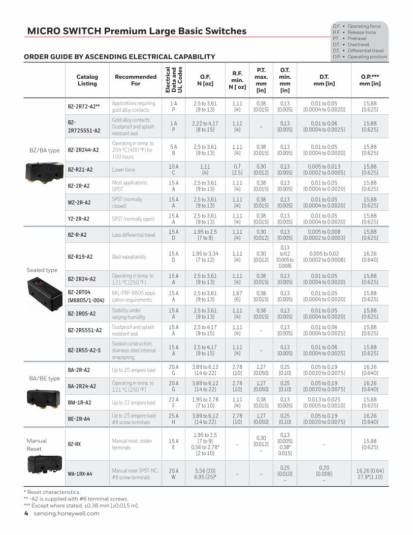
ORDER GUIDE BY ASCENDING ELECTRICAL CAPABILITY
Catalog Listing
Recommended For
Ele
ctri
cal
Dat
a an
d U
L C
odes
O.F.N [oz]
R.F. min.
N [ oz]
P.T. max.mm [in]
O.T. min.mm [in]
D.T.mm [in]
O.P.***mm [in]
BZ/BA type
BZ/BA Type
BZ-2R72-A2** Applications requiring gold alloy contacts
1 AP
2,5 to 3,61 [9 to 13]
1,11[4]
0,38[0.015]
0,13[0.005]
0,01 to 0,05[0.0004 to 0.0020]
15,88[0.625]
BZ-2R725551-A2
Gold alloy contacts;Dustproof and splashresistant seal
1 AP
2,22 to 4,17[8 to 15]
1,11[4] – 0,13
[0.005]0,01 to 0,06
[0.0004 to 0.0025]15,88
[0.625]
BZ-2R244-A2Operating in temp. to204 °C [400 °F] for100 hours
5 AB
2,5 to 3,61 [9 to 13]
1,11[4]
0,38[0.015]
0,13[0.005]
0,01 to 0,05[0.0004 to 0.0020]
15,88[0.625]
BZ-R21-A2 Lower force 10 AC
1,11[4]
0,7[2.5]
0,30 [0.012]
0,13[0.005]
0,005 to 0,013[0.0002 to 0.0005]
15,88[0.625]
BZ-2R-A2 Most applicationsSPDT
15 AA
2,5 to 3,61 [9 to 13]
1,11[4]
0,38[0.015]
0,13[0.005]
0,01 to 0,05[0.0004 to 0.0020]
15,88[0.625]
WZ-2R-A2 SPST (normallyclosed)
15 AA
2,5 to 3,61 [9 to 13]
1,11[4]
0,38[0.015]
0,13[0.005]
0,01 to 0,05[0.0004 to 0.0020]
15,88[0.625]
YZ-2R-A2 SPST (normally open) 15 AA
2,5 to 3,61 [9 to 13]
1,11[4]
0,38[0.015]
0,13[0.005]
0,01 to 0,05[0.0004 to 0.0020]
15,88[0.625]
Sealed type
Sealed type
BZ-R-A2 Less differential travel 15 AD
1,95 to 2.5[7 to 9]
1,11[4]
0,30 [0.012]
0,13[0.005]
0,005 to 0,008[0.0002 to 0.0003]
15,88[0.625]
BZ-R19-A2 Best repeatability 15 AD
1,95 to 3,34[7 to 12]
1,11[4]
0,30 [0.012]
0,13 to 0,2
[0.005 to 0.008]
0,005 to 0,02[0.0002 to 0.0008]
16,26[0.640]
BZ-2R24-A2 Operating in temp. to 121 °C [250 °F]
15 AA
2,5 to 3,61 [9 to 13]
1,11[4]
0,38[0.015]
0,13[0.005]
0,01 to 0,05[0.0004 to 0.0020]
15,88[0.625]
BZ-2RT04(M8805/1-004)
MIL-PRF-8805 appli-cation requirements
15 AA
2,5 to 3,61 [9 to 13]
1,67[6]
0,38[0.015]
0,13[0.005]
0,01 to 0,05[0.0004 to 0.0020]
15,88[0.625]
BZ-2R05-A2 Stability undervarying humidity
15 AA
2,5 to 3,61 [9 to 13]
1,11[4]
0,38[0.015]
0,13[0.005]
0,01 to 0,05[0.0004 to 0.0020]
15,88[0.625]
BZ-2R5551-A2 Dustproof and splashresistant seal
15 AA
2,5 to 4,17 [9 to 15]
1,11[4] – 0,13
[0.005]0,01 to 0,06
[0.0004 to 0.0025]15,88
[0.625]
BZ-2R55-A2-SSealed construction; stainless steel internal snapspring
15 AA
2,5 to 4,17 [9 to 15]
1,11[4] – 0,13
[0.005]0,01 to 0,06
[0.0004 to 0.0025]15,88
[0.625]
BA/BE typeBA-2R-A2 Up to 20 ampere load 20 A
G3,89 to 6,12
[14 to 22]2,78[10]
1,27 [0.050]
0,25 [0.10]
0,05 to 0,19[0.0020 to 0.0075]
16,26[0.640]
BA-2R24-A2 Operating in temp. to 121 °C [250 °F]
20 AG
3,89 to 6,12 [14 to 22]
2,78[10]
1,27 [0.050]
0,25 [0.10]
0,05 to 0,19[0.0020 to 0.0075]
16,26[0.640]
BM-1R-A2 Up to 22 ampere load 22 AF
1,95 to 2,78 [7 to 10]
1,11[4]
0,38[0.015]
0,13[0.005]
0,013 to 0,025[0.0005 to 0.0010]
15,88[0.625]
BE-2R-A4 Up to 25 ampere load;#8 screw terminals
25 AH
3,89 to 6,12 [14 to 22]
2,78[10]
1,27 [0.050]
0,25 [0.10]
0,05 to 0,19[0.0020 to 0.0075]
16,26[0.640]
Manual Reset
BZ-RX Manual reset, solderterminals
15 AE
1,95 to 2,5[7 to 9]
0,56 to 2,78*[2 to 10]
–0,30
[0.012]–
0,13 [0.005]0,38*
0.015]
– 15,88[0.625]
WA-1RX-A4 Manual reset SPST-NC; #8 screw terminals
20 AW
5,56 [20]6,95 [25]* – –
0,25[0.010]
–
0,20[0.008]
–
16,26 [0.64]27,9*[1.10]
* Reset characteristics.** -A2 is supplied with #6 terminal screws.*** Except where stated, ±0,38 mm [±0.015 in].
O.F. • Operating forceR.F. • Release forceP.T. • PretravelO.T. • OvertravelD.T. • Differential travelO.P. • Operating position

Sensing and Internet of Things 5
MICRO SWITCH Premium Large Basic Switches O.F. • Operating forceR.F. • Release forceP.T. • PretravelO.T. • OvertravelD.T. • Differential travelO.P. • Operating positionOVERTRAVEL PLUNGER ORDER GUIDE
Catalog Listing Recommended For
Ele
ctri
cal
Dat
a an
d U
L C
odes
O.F.N [oz]
R.F. min.
N [ oz]
P.T. max.mm [in]
O.T. min.mm [in]
D.T.mm [in]
O.P.***mm [in]
BZ-2RD72-A2 Applications requiring gold alloy contacts
1 AP
2,5 to 3,61 [9 to 13]
1,11[4]
0,38[0.015]
1,52[0.060]
0,01 to 0,05[0.0004 to 0.0020]
21,21[0.835]
BZ-2RD-A2Added overtravel. Formanual operation and slow 20° (max) cam rise
15 AA
2,5 to 3,61 [9 to 13]
1,11[4]
0,38[0.015]
1,52[0.060]
0,01 to 0,05[0.0004 to 0.0020]
21,21[0.835]
BZ-2RD24-A2 Operating in temperatureto 121 °C [250 °F]
15 AA
2,5 to 3,61 [9 to 13]
1,11[4]
0,38[0.015]
1,52[0.060]
0,01 to 0,05[0.0004 to 0.0020]
21,21[0.835]
BM-1RD-A2 Up to 22 ampere load 22 AF
1,95 to 2,78[7 to 10]
1,11[4]
0,38[0.015]
1,52[0.060]
0,013 to 0,025[0.0005 to 0.0010]
21,21[0.835]
BZ-2RDS725551-A2
Applications requiring gold alloy contacts plusdustproof and splashresistant seal
1 AP
3,61 to 5,28[13 to 19]
1,11[4] – 1,52
[0.060]0,01 to 0,063
[0.0004 to 0.0025]28,20
[1.110]
BZ-2RDS5551-A2 Dustproof and splashresistant seal
15 AA
3,61 to 5,28[13 to 19]
1,11[4] – 1,52
[0.060]0,01 to 0,063
[0.0004 to 0.0025]28,20
[1.110]
BA-2RB-A2 Up to 20 ampere load 20 AG
3,89 to 6,12 [14 to 22]
2,78[10]
1,27[0.050]
2,39[0.094]
0,05 to 0,019[0.0020 to 0.0075]
26,20[1.03]
BE-2RB-A4 Up to 25 ampere load; #8 screw terminals
25 AH
3,89 to 6,12 [14 to 22]
2,78[10]
1,27[0.050]
2,39[0.094]
0,05 to 0,019[0.0020 to 0.0075]
26,20[1.03]
BZ-2RS72-A2 Applications requiring gold alloy contacts
1 AP
2,5 to 3,61 [9 to 13]
1,11[4]
0,38[0.015]
1,52[0.060]
0,01 to 0,05[0.0004 to 0.0020]
28,20[1.110]
BZ-2RS-A2Added overtravel. Forin-line operation and with JR aux. actuators
15 AA
2,5 to 3,61 [9 to 13]
1,11[4]
0,38[0.015]
1,52[0.060]
0,01 to 0,063[0.0004 to 0.0025]
28,20[1.110]
BZ-2RS24-A2 Operating in temperatureto 121 °C [250 °F]
15 AA
2,5 to 3,61 [9 to 13]
1,11[4]
0,38[0.015]
1,52[0.060]
0,01 to 0,05[0.0004 to 0.0020]
28,20[1.110]
BZ-2RST04(M8805/1-012)
MIL-PRF-8805 application requirements
15 AA
2,5 to 3,61 [9 to 13]
1,67[6]
0,38[0.015]
1,52[0.060]
0,01 to 0,05[0.0004 to 0.0020]
28,20[1.110]
BZ-RSX Manual reset;solder terminals
15 AE
1,95 to 2,64[7 to 9] – 0,30
[0.012]0,65
[0.025] – 2,79[1.11]
BM-1RS-A2 Up to 22 ampere load 22 AF
1,95 to 2,78[7 to 10]
1,11[4]
0,38[0.015]
1,52[0.060]
0,013 to 0,025[0.0005 to 0.0010]
28,20[1.110]
BZ-2RS7225551-A2
Applications requiring goldalloy contacts plusdustproof and splashresistant seal
1 AP
2,5 to 4,17 [9 to 15]
1,11[4] – 1,52
[0.060]0,01 to 0,063
[0.0004 to 0.0025]28,20
[1.110]
BZ-2RS5551-A2 Dustproof and splashresistant seal
15 AA
2,5 to 4,17 [9 to 15]
1,11[4] – 1,52
[0.060]0,01 to 0,063
[0.0004 to 0.0025]28,20
[1.110]
* ±51 mm [±0.020 in].*** Except where stated, ±0,38 mm [±0.015 in].

6 sensing.honeywell.com
MICRO SWITCH Premium Large Basic Switches
OVERTRAVEL PLUNGER ORDER GUIDE
Catalog Listing
Recommended For
Ele
ctri
cal
Dat
a an
d U
L C
odes
O.F.N [oz]
R.F. min.
N [ oz]
P.T. max.mm [in]
O.T. min.mm [in]
D.T.mm [in]
O.P.***mm [in]
BZ-2RQ-A2
Added overtravel. Formanual in-line operation and for slow 30° (max) rise cams
15 AA
2,5 to 3,61 [9 to 13]
1,11[4]
0,38[0.015]
5,56[0.219]
0,01 to 0,05[0.0004 to 0.0020]
38,10 ±0,51[1.50 ±0.02]
BZ-2RQ24-A2 Operating in temperatureto 121 °C [250 °F]
15 AA
2,5 to 3,61 [9 to 13]
1,11[4]
0,38[0.015]
5,56[0.219]
0,01 to 0,05[0.0004 to 0.0020]
38,10 ±0,51[1.50 ±0.02]
BZ-2RQ172-A2 Applications requiring gold alloy contacts
1 AP
2,5 to 3,61 [9 to 13]
1,11[4]
0,38[0.015]
5,56[0.219]
0,01 to 0,05[0.0004 to 0.0020]
21,82[0.859]
BZ-2RQ1-A2 BZ-2RQ-A2 type applica-tions with panel mount
15 AA
2,5 to 3,61 [9 to 13]
1,11[4]
0,38[0.015]
5,56[0.219]
0,01 to 0,05[0.0004 to 0.0020]
21,82[0.859]
BZ-2RQ1T04(M8805/1-020)
MIL-PRF-8805 application requirements
15 AA
2,5 to 3,61 [9 to 13]
1,67[6]
0,38[0.015]
5,56[0.219]
0,01 to 0,05[0.0004 to 0.0020]
21,82[0.859]
BZ-2RQ124-A2 Operating in temperatureto 121 °C [250 °F]
15 AA
2,5 to 3,61 [9 to 13]
1,11[4]
0,38[0.015]
5,56[0.219]
0,01 to 0,05[0.0004 to 0.0020]
21,82[0.859]
BZ-2RN702Furnished withunassembled sealboot
15 AX
2,5 to 3,61 [9 to 13]
1,11[4]
0,38[0.015]
3,18[0.125]
0,01 to 0,05[0.0004 to 0.0020]
48,4 ±0,501.906 [±0.02]
BZ-RQ1X Manual reset;Solder terminals
15 AE
1,67 to 2,64[6 to 9.5] – 0,30
[0.012]5,56
[0.219] –23,42 ±1,14
[0.922 ±0.045]7,14* [0.281*]
BA-2RQ1-A2 Up to 20 ampere load 20 AG
3,89 to 6,12[14 to 22]
2,78[10]
1,27[0.050]
5,56[0.219]
0,05 to 0,19[0.0020 to 0.0075]
21,82[0.859]
BM-1RQ1-A2 Up to 22 ampere load 22 AF
1,95 to 2,78[7 to 10]
1,11[4]
0,38[0.015]
5,56[0.219]
0,013 to 0,025[0.0005 to 0.0010]
21,82[0.859]
BZ-2RQ1872-A2 Applications requiring goldalloy contacts
1 AP
2,5 to 3,61 [9 to 13]
1,11[4]
0,38[0.015]
3,56[0.140]
0,01 to 0,05[0.0004 to 0.0020]
33,32 ±1,14[1.31 ±0.045]
BZ-2RQ18-A2
Added overtravel. Rollerplunger for rapid cam (30°max) rise and slideoperation. Panel mount
15 AA
2,5 to 3,61 [9 to 13]
1,11[4]
0,38[0.015]
3,56[0.140]
0,01 to 0,05[0.0004 to 0.0020]
33,32 ±1,14[1.31 ±0.045]
BZ-2RQ1824-A2 Operating in temperatureto 121 °C [250 °F]
15 AA
2,5 to 3,61 [9 to 13]
1,11[4]
0,38[0.015]
3,56[0.140]
0,01 to 0,05[0.0004 to 0.0020]
33,32 ±1,14[1.31 ±0.045]
BZ-2AQ18T1 Double-break circuitry 15 AT
3,89 to 6,68[14 to 24]
1,11[4]
0,69[0.025]
3,58[0.141]
0,03 to 0,10[0.001 to 0.004]
33,35 ±1,19[1.31 ±0.047]
BM-1RQ18-A2 Up to 22 ampere load 22 AF
1,95 to 2,78[7 to 10]
1,11[4]
0,38[0.015]
3,56[0.140]
0,013 to 0,025[0.0005 to 0.0010]
33,32 ±1,14[1.31 ±0.045]
BZ-2RQ181-A2Applications requiringroller plunger 90° to majoraxis of switch
15 AA
2,5 to 3,61 [9 to 13]
1,11[4]
0,38[0.015]
3,56[0.140]
0,01 to 0,05[0.0004 to 0.0020]
33,32 ±1,14[1.31 ±0.045]
* Reset characteristics** Except where stated, ±0,76 mm [±0.030 in]*** Except where stated, ±0,38 mm [±0.015 in].
O.F. • Operating forceR.F. • Release forceP.T. • PretravelO.T. • OvertravelD.T. • Differential travelO.P. • Operating position

Sensing and Internet of Things 7
MICRO SWITCH Premium Large Basic SwitchesO.F. • Operating forceR.F. • Release forceP.T. • PretravelO.T. • OvertravelD.T. • Differential travelO.P. • Operating positionSTRAIGHT LEVER ORDER GUIDE
Catalog Listing Recommended For
Ele
ctri
cal
Dat
a an
d U
L C
odes
O.F.N [oz]
R.F. min.
N [ oz]
P.T. max.mm [in]
O.T. min.mm [in]
D.T.mm [in]
O.P.***mm [in]
BZ-2RW8072-A2 Applications requiring gold alloy contacts
1 AP
0,7[2.5]
0,14[0.5] – 5,56
[0.219]0,18 to 1,27
[0.007 to 0.050]19,1
[0.750]
BZ-2RW80722555105-A2Stability under varying hu-midity. Gold alloy contacts with seal
1 AP
0,7[2.5]
0,14[0.5] – 5,56
[0.219]0,18 to 1,27
[0.007 to 0.050]19,1
[0.750]
BZ-2RW8244-A2Operating in temp.to 204 °C [400 °F]for 100 hours
5 AB
0,7[2.5]
0,14[0.5] – 5,56
[0.219]0,18 to 1,27
[0.007 to 0.050]19,1
[0.750]
BZ-RW8435-A2Lowest operatingforce (without external return spring)
10 AI
0,07[0.25] – 6,76
[0.266]5,56
[0.219]0,08 to 0,38
[0.003 to 0.015]19,1
[0.750]
BZ-2RW876T 1.25-inch lever 15 AA
1,67[6]
0,42[1.5] – 0,42
[0.141]0,10 to 0,63
[0.004 to 0.025]19,1
[0.750]
BZ-2RW80-A2 2.5-inch lever 15 AA
0,7[2.5]
0,14[0.5] – 5,56
[0.219]0,18 to 1,27
[0.007 to 0.050]19,1
[0.750]
BZ-2RW84-A2 Lower force (withoutexternal return spring)
15 AA
0,28[1]
0,03[0.125]
8,33[0.328]
5,56[0.219]
0,18 to 1,27[0.007 to 0.050]
19,1[0.750]
BZ-2RW805551-A2 Dustproof andsplash resistant seal
15 AA
0,7[2.5]
0,14[0.5] – 5,56
[0.219]0,18 to 1,27
[0.007 to 0.050]19,1
[0.750]
BZ-2RWT04 (M8805/1-044)
MIL-PRF-8805application requirements
15 AA
0,28 to 0,90[1 to
3.25]
0,21[0.75]
7,52[0.296]
4,37[0.172]
2,36[0.093]
19,1[0.750]
BZ-2RW824-A2 Operating in temperatureto 121 °C [250 °F]
15 AA
0,7[2.5]
0,14[0.5] – 5,56
[0.219]0,18 to 1,27
[0.007 to 0.050]19,1
[0.750]
BZ-RW80X Manual reset, solder terminals
15 AE
0,63[2.25] – –
5,56[0.219]
0,38*[0.015]
–
19,05[0.750]
7,14*[0.281]
BZ-2RW863-A2 6-inch lever 15 AA
0,28[1] – – 12,7
[0.50]0,46 to 3,68
[0.018 to 0.145]19,1 ±1,52
[0.75 ±0.06]
BA-2RV-A2 Up to 20 ampere load 20 AG
0,7[2.5]
0,14[0.5]
15,88[0.625]
1,98[0.078]
2,77 max.[0.109] max.
19,1[0.750]
BM-1RW84-A2 Up to 22 ampere load 22 AF
0,28[1]
0,03[0.125]
7,54[0.297]
5,56[0.219]
0,13 to 0,84[0.005 to 0.033]
19,1[0.750]
BE-2RV-A4 Up to 25 ampere load#8 screw terminals
25 AH
0,7[2.5]
0,14[0.5]
15,88[0.625]
1,98[0.078]
2,77 max.[0.109] max.
19,1[0.750]
BZ-2RW899-A2Adjustable operating point 17 mm to 22 mm [0.67 in to 0.88 in]
15 AA
0,7[2.5]
0,14[0.5] – 3,54***
[0.125]0,18 to 1,27
[0.007 to 0.050]
17,02 to 22,35
[0.670 to 0.880]
BZ-2RM-A2Reverse acting actuator (switch plunger depressedin free position)
15 AA
1,67[6]
0,28[1]
5,56[0.219]
5,56[0.219]
0,10 to 0,89[0.004 to 0.035]
19,1[0.750]
* Reset characteristics.** Except where stated ±0,76 mm [±0.030 in].*** From 17 mm [0.670 in] O.P.

8 sensing.honeywell.com
MICRO SWITCH Premium Large Basic SwitchesO.F. • Operating forceR.F. • Release forceP.T. • PretravelO.T. • OvertravelD.T. • Differential travelO.P. • Operating positionSIMULATED ROLLER AND ROLLER LEVER ORDER GUIDE
Catalog Listing Recommended For
Ele
ctri
cal
Dat
a an
d U
L C
odes
O.F.N [oz]
R.F. min.
N [ oz]
P.T. max.mm [in]
O.T. min.mm [in]
D.T.mm [in]
O.P.***mm [in]
BZ-2RW80147-A21.05 inch (26,7 mm)(simulated roller)lever applications
15 AA
1,67[6]
0,42[1.5] – 2,39
[0.094]0,08 to 0,51
[0.003 to 0.020]30,17
[1.188]
BZ-2RW80196-A21.90 inch (48,3 mm)(simulated roller)lever applications
15 AA
0,97[3.5]
0,21[0.75] – 3,96
[0.156]0,10 to 1,0
[0.004 to 0.040]
30,17 ±0,76[1.188 ±0.03]
BZ-2RW82272-A2Applicationsrequiring gold alloycontacts
1 AP
1,67[6]
0,42[1.5] – 2,39
[0.094]0,08 to 0,51
[0.003 to 0.020]30,17
[1.188]
BZ-2RW822725551-A2Apps requiring gold alloycontacts plus dustproof and splash resistant seal
1 AP
1,67[6]
0,42[1.5] – 2,39
[0.094]0,08 to 0,51
[0.003 to 0.020]30,17
[1.188]
BZ-2RW822-A2 26,7 mm [1.05 in]roller lever
15 AA
1,67[6]
0,42[1.5] – 2,39
[0.094]0,08 to 0,51
[0.003 to 0.020]30,17
[1.188]
BZ-2RW8222-A2 Roller turned 90° 15 AA
0,7 to 1,81[2.5 to 6.5]
0,35[1.25] –
3,58[0.141]
max.
0,08 to 0,51[0.003 to 0.020]
30,75[1.25]
BZ-2RW82224-A2Operating intemperature to121 °C [250 °F]
15 AA
1,67[6]
0,42[1.5] – 2,39
[0.094]0,08 to 0,51
[0.003 to 0.020]30,17
[1.188]
BZ-2RW8225551-A2 Dustproof andsplash resistant seal
15 AA
1,67[6]
0,42[1.5] – 2,39
[0.094]0,08 to 0,51
[0.003 to 0.020]30,17
[1.188]
BZ-2RW82255-A2-S
Best service forsealed construction;stainless steelinternal snap spring.
15 AA
1,67[6]
0,42[1.5] – 2,39
[0.094]0,08 to 0,51
[0.003 to 0.020]30,17
[1.188]
BA-2RV22-A2 Up to 20 ampere load 20 G
1,67[6]
0,42[1.5]
6,35[0.250]
0,76[0.030]
1,14[0.045] max.
29,77[1.172]
BM-1RW822-A2 Up to 22 ampere load 22F
1,67[6]
0,42[1.5] – 2,39
[0.094]0,025 to 0,33
[0.001 to 0.013]30,17
[1.188]
BE-2RV22-A4 Up to 25 ampere load; #8 screw terminals
25H
1,67[6]
0,42[1.5]
6,35[0.250]
0,76[0.030]
1,14[0.045] max.
29,77[1.172]
BZ-2RW82299-A2Adjustable operatingpoint. Roller lever1.05 inch (26,7 mm)
15 AA
1,67[6]
0,42[1.5] – 1,02
[0.040]0,08 to 0,51
[0.003 to 0.020]
29,77 to 30,56
[1.172 to 1.203]
BZ-2RW8299-A2Adjustable operatingpoint. Roller lever1.90 inch (48,3 mm)
15 AA
0,97[3.5]
0,21[0.75] – 2,16
[0.085]0,10 to 1,0
[0.004 to 0.040]
29,2 to 31,5[1.150 to
1.24]
** Except where stated ±0,38 mm [±0.015 in].

Sensing and Internet of Things 9
MICRO SWITCH Premium Large Basic Switches O.F. • Operating forceR.F. • Release forceP.T. • PretravelO.T. • OvertravelD.T. • Differential travelO.P. • Operating positionROLLER LEVER ORDER GUIDE
Catalog Listing Recommended For
Ele
ctri
cal
Dat
a an
d U
L C
odes
O.F.N [oz]
R.F. min.
N [ oz]
P.T. max.mm [in]
O.T. min.mm [in]
D.T.mm [in]
O.P.***mm [in]
BZ-2RW82725551-A2
Applications requiringgold alloy contacts,plus dustproof, andsplash resistant seal
1 AP
0,97[3.5]
0,21[0.75] – 3,96
[0.156]0,10 to 1,0
[0.004 to 0.040]
30,17 ±0,76[1.188
±0.030]
BZ-2RW82-A21.90 inch (48,3 mm)(steel roller) leverapplications
15 AA
0,97[3.5]
0,21[0.75] – 3,96
[0.156]0,10 to 1,0
[0.004 to 0.040]
30,17 ±0,76[1.188
±0.030]
BZ-2RW825551-A2 Dustproof and splashresistant seal
15 AA
0,97[3.5]
0,21[0.75] – 3,96
[0.156]0,10 to 1,0
[0.004 to 0.040]
30,17 ±0,76[1.188
±0.030]
BZ-2RW8224-A2 Operating in temperature to 121 °C [250 °F]
15 AA
0,97[3.5]
0,21[0.75] – 3,96
[0.156]0,10 to 1,0
[0.004 to 0.040]
30,17 ±0,76[1.188
±0.030]
BA-2RV2-A2 Up to 20 ampere load 20 AG
0,97[3.5]
0,14[0.5]
11,89[0.468]
1,52[0.060]
2,16[0.085]
30,17 ±0,76[1.188
±0.030]
BM-1RW82-A2 Up to 22 ampere load 22 AF
0,97[3.5]
0,21[0.75] – 3,96
[0.156]0,08 to 0,56
[0.003 to 0.022]
30,17 ±0,76[1.188
±0.030]
BE-2RV2-A4 Up to 25 ampere load; #8 screw terminals
25 AH
0,97[3.5]
0,14[0.5]
11,89[0.468]
1,52[0.060]
2,16[0.085]
30,17 ±0,76[1.188
±0.030]
BZ-RW922-A2 Best repeatability andO.P. stability
10 AI
3,34[12]
1,11[4]
0,35[0.015]
2,54[0.100]
0,013 to 0,025[0.0005 to 0.0010]
31,37[1.235]
BZ-2RW826-A2One-way roller 9,4mm x 3,8 mm [0.37 india. x 0.15 in] wide roller
15 AA
1,67 [6]
0,42[1.5] – 2,39
[0.094]0,08 to 0,51
[0.003 to 0.020]41,34
[1.625]
BZ-2RW825-A2One-way roller 4,83mm x 4,83 mm [0.19 india. x 0.19 in] wide roller
15 AA
2,22[8]
0,42[1.5] – 1,52
[0.060]0,38
[0.015]28,96[1.14]
NOTE: For adjustable operate point and simulated roller lever switches, refer to previous page.** Except where stated ±0,38 mm [±0.015 in].

10 sensing.honeywell.com
MICRO SWITCH Premium Large Basic Switches
FLEXIBLE LEAF AND FLEXIBLE ROLLER LEAF ORDER GUIDE
Catalog Listing
Recommended For
Ele
ctri
cal
Dat
a an
d U
L C
odes
O.F.N [oz]
R.F. min.
N [ oz]
P.T. max.mm [in]
O.T. min.mm [in]
D.T.mm [in]
O.P.***mm [in]
BZ-2RL-A2 Force and stability of theflexible leaf actuator
15 AA
1,39[5]
0,14[0.5] – 1,52
[0.060]1,27
[0.050]17,48
[0.688]
BZ-2RL5551-A2 Dustproof and splashresistant seal
15 AA
1,95[7]
0,14[0.5] – 1,52
[0.060]1,27
[0.050]17,48
[0.688]
BZ-2RLT04 (M8805/1-001)
MIL-PRF-8805 application requirements
15 AA
1,39[5]
0,14[0.5] – 1,52
[0.060]1,27
[0.050]17,48
[0.688]
BZ-2RL24-A2 Operating in temperatureto 121 °C [250 °F]
15 AA
1,39[5]
0,14[0.5] – 1,52
[0.060]1,27
[0.050]17,48
[0.688]
BZ-RLX Manual reset;solder terminals
15 AE
0,83 [3] – –
1,57 [0.062]
0,38*[0.015]
–
17,48[0.688]
7,14*[0.281]
BA-2RL-A2 Up to 20 ampere load 20 AG
2,5[9]
0,28[1] – 1,57
[0.062]1,57
[0.062]17,48
[0.688]
BE-2RL-A4 Up to 25 ampere load, #8 screw terminals
25 AH
2,5[9]
0,28[1] – 1,57
[0.062]1,57
[0.062]17,48
[0.688]
BZ-RL24-A2 Operating in temp. to 121 °C [250 °F] for 100 hours
5 AB
1,39[5]
0,14[0.5] – 1,52
[0.060]1,27
[0.050]28,6
[1.125]
BZ-2RL2-A2 Force and stability of theflexible leaf with roller
15 AA
1,39[5]
0,14[0.5] – 1,52
[0.060]1,27
[0.050]28,6
[1.125]
BZ-2RL25551-A2
Dustproof and splashresistant seal
15 AA
1,95[7]
0,14[0.5] – 1,52
[0.060]1,27
[0.050]28,6
[1.125]
BZ-2RL2T04(M8805/1-036)
MIL-PRF-8805 appli-cationrequirements
15 AA
1,04 to 1,39[3.75 to 5]
0,14[0.5] – 1,52
[0.060]1,27
[0.050]28,6
[1.125]
BA-2RL2-A2 Up to 20 ampere load 20 AG
2,5[9]
0,28[1] – 1,52
[0.060]1,65
[0.065]28,6
[1.125]
BE-2RL2-A4 Up to 25 ampere load, #8 screw terminals
25 AH
2,5[9]
0,28[1] – 1,52
[0.060]1,65
[0.065]28,6
[1.125]
NOTE: For adjustable operate point and simulated roller lever switches, refer to previous page.** Except where stated ±0,76 mm [±0.030 in].
O.F. • Operating forceR.F. • Release forceP.T. • PretravelO.T. • OvertravelD.T. • Differential travelO.P. • Operating position

Sensing and Internet of Things 11
MICRO SWITCH Premium Large Basic Switches
STANDARD ACTUATOR OPTIONS, TERMINALS, & DIMENSIONS
BZ/BM Series: Pin plunger BA/BE Series: Pin plunger
2,3 mm [0.09 in] dia
15,0 mm[0.59 in]
15,7 mm[0.62 in]
O.P.
3,6 mm[0.14 in]
dia.
3,6 mm[0.14 in]
9,1 mm[0.36 in]
11,9
mm
[0.4
7 in
]
49,3 mm[1.94 in]
25,4 mm[1.00 in]
4,3 mm [0.17 in]
dia.
0,2 mm[0.01 in]
P.T. 23,37 mm[0.92 in]
SST plunger SST plunger2,3 mm [0.09 in] dia
15,0 mm[0.59 in]
16,2 mm[0.64 in]
O.P.
3,6 mm[0.14 in]
dia.
3,6 mm[0.14 in]
9,1 mm[0.36 in]
11,9
mm
[0.4
7 in
]
49,3 mm[1.94 in]
25,4 mm[1.00 in]
4,3 mm [0.17 in]
dia.
1,27 mm[0.05 in]
P.T. 19,05 mm [0.75 in]
5,3 mm[0.21 in]
BZ/BM Series: Overtravel plunger BA/BE Series: Overtravel plunger
3,6 mm[0.14 in]
dia.
3,6 mm[0.14 in]
9,1 mm[0.36 in]
14,5 mm[0.57 in]
0,25 mm[0.01 in]
max.P.T. 13,5 mm
[0.53 in]dia.
7,11 mm [0.28 in] dia.
21,1 mm[0.83 in]
O.P.
4,3 mm[0.17 in]
dia.49,3 mm[1.94 in]
25,4 mm[1.00 in]
11,9
mm
[0.4
7 in
]
4,06 mm[0.16 in]
Plated steel plunger
23,37 mm[0.92 in]
3,6 mm[0.14 in]
dia.
3,6 mm[0.14 in]
9,1 mm[0.36 in]
14,9 mm[0.59 in]
12,7 mm[0.05 in]
max.P.T.
7,1 mm[0.28 in]
dia.
15,0 mm [0.59 in] dia.
26,1 mm[1.03 in]
O.P.
4,3 mm[0.17 in]
dia.
49,3 mm [1.94 in]
25,4 mm[1.00 in]
11,9
mm
[0.4
7 in
]
7,62 mm[0.30 in]
SST plunger
19,05 mm[0.75 in]
5,3 mm[0.21 in]
BZ/BM Series: Bushing-mount overtravel plunger BA/BE Series: Bushing-mount overtravel plunger
9,1 mm[0.36 in]
21,8 mm[0.86 in]
O.P.
14,5 mm[0.57 in]
3,6 mm[0.14 in]
dia.
3,6 mm[0.14 in]
8,1 mm[0.32 in]
dia.
4,3 mm[0.17 in]
dia. 49,3 mm[1.94 in]
25,4 mm[1.00 in]
11,9
mm
[0.4
7 in
]
5,3 mm[0.21 in]
16,0 mm[0.63 in]
Plated steel plunger
0,2 mm[0.01 in]
max.P.T.
13,2 mm[0.52 in]
23,37 mm [0.92 in]
9,1 mm[0.36 in]
21,8 mm[0.86 in]
O.P.
14,5 mm[0.57 in]
3,6 mm[0.14 in]
dia.
3,6 mm[0.14 in]
8,1 mm[0.32 in]
dia.
4,3 mm[0.17 in]
dia.49,3 mm[1.94 in]
25,4 mm[1.00 in]
11,9
mm
[0.4
7 in
]
5,3 mm[0.21 in]
16,0 mm[0.63 in]
Plated steel plunger
1,27 mm[0.05 in]
max.P.T.
13,2 mm[0.52 in]
19,05 mm [0.75 in]
NOTE: Typical switch width is 17,5 mm [0.69 in]

12 sensing.honeywell.com
MICRO SWITCH Premium Large Basic Switches
STANDARD ACTUATOR OPTIONS, TERMINALS, & DIMENSIONS
BZ/BM Series: Flexible leaf actuator BA/BE Series: Flexible leaf actuator
3,6 mm[0.14 in]
dia.
3,6 mm[0.14 in]
9,1 mm[0.36 in]
14,7 mm[0.58 in]
49,5 mm[1.95 in]
17,5 mm[0.69 in]
O.P.
4,3 mm[0.17 in]
dia.49,3 mm[1.94 in]
25,4 mm[1.00 in] 11
,9 m
m[0
.47
in]
5,3 mm[0.21 in]
20,5 mm[0.81 in]
F.P.
SST lever
3,6 mm[0.14 in]
dia.
3,6 mm[0.14 in]
9,1 mm[0.36 in]
14,7 mm[0.58 in]
45,2 mm[1.78 in]
17,5 mm[0.69 in]
O.P.
4,3 mm[0.17 in]
dia. 49,3 mm[1.94 in]
25,4 mm[1.00 in] 11
,9 m
m[0
.47
in]
5,3 mm[0.21 in]
25,4 mm[1.00 in]
F.P.
SST lever
BZ/BM Series: Straight lever with external return spring BA/BE Series: Straight lever
9,1 mm[0.36 in]
19,10.75O.P.
27,2 mm[1.07 in]
F.P.
3,6 mm[0.14 in]
dia.
3,6 mm[0.14 in]
9,6 mm[0.38 in]
63,5 mm[2.50 in]
R
16,8 mm[0.66 in]
4,3 mm[0.17 in]
dia.49,3 mm[1.94 in]
25,4 mm[1.00 in]
11,9
mm
[0.4
7 in
]
5,3 mm[0.21 in]
20,0 mm[0.79 in]
F.P.
SST lever
9,1 mm[0.36 in]
19,0 mm[0.75 in]
O.P.
34,8 mm[1.37 in]
F.P.
3,6 mm[0.14 in]
dia.
3,6 mm[0.14 in]
9,6 mm[0.38 in]
63,5 mm[2.50 in]
R
16,5 mm[0.69 in]
4,3 mm[0.17 in]
dia. 49,3 mm[1.94 in]
25,4 mm[1.00 in]
11,9
mm
[0.4
7 in
]
5,3 mm[0.21 in]
20,8 mm[0.82 in]
SST lever
BZ/BM Series: Roller lever with external return spring Pin plunger with manual reset
9,1 mm[0.36 in]
29,9 mm[1.18 in]
O.P.
32,0 mm[1.26 in]
F.P.
3,6 mm[0.14 in]
dia.
3,6 mm[0.14 in]
9,7 mm[0.38 in]
25,9 mm[1.02 in]
4,3 mm[0.17 in]
dia.49,3 mm[1.94 in]
25,4 mm[1.00 in]
11,9
mm
[0.4
7 in
]
5,3 mm[0.21 in]
20,0 mm[0.79 in]
SST roller26,7 mm[1.05 in]
R
2,3 mm [0.09 in] dia
14,9 mm[0.59 in]
27,9 mm[1.10 in]R.O.P.
3,6 mm[0.14 in]
dia.
3,6 mm[0.14 in]
9,6 mm[0.38 in]
11,9
mm
[0.4
7 in
]
49,3 mm[1.94 in]
25,4 mm[1.00 in]
5,3 mm [0.21 in]
SST plunger
16,2 mm[0.64 in]
O.P.
11,9 mm [0.47 in]
28,7 mm [1.13 in]
F.P.
19,05 mm [0.75 in]
NOTE: Typical switch width is 17,5 mm [0.69 in]

Sensing and Internet of Things 13
MICRO SWITCH Premium Large Basic Switches
6AS SERIES - PREMIUM LARGE SNAP-ACTION TANDEM SWITCH ASSEMBLY
The MICRO SWITCH 6AS Series consists of two large premium BZ/BA/BM/BE snap-action switches ganged together and actuated by a single actuator. Operating characteristics are dependent upon the type of individual switches and actuators chosen. Field adjustable oper-ating point on one or both basic switches. Solder, A2, and T-type terminations available, along with straight, roller, and leaf levers. Mounting holes accept pins or screws of 3,53 mm [0.139 in] diameter. Often used for boiler controls or anywhere two circuits need to be controlled by one actuator.
O.F. • Operating forceR.F. • Release forceO.T. • OvertravelD.T. • Differential travelO.P. • Operating position6AS SERIES ORDER GUIDE
Cat
alog
Li
stin
g
Recommended For
Ele
ctri
cal
Dat
a an
d U
L C
odes
Leve
r le
ngth
Term
inal
ty
pe O.F.N [oz]
R.F. min.N [ oz]
O.T. min. mm [in]
D.T.mm [in]
O.P.*mm [in]
6AS34 Centered lever. Adjustment over switch D
15 AA
30,56 mm [1.203 in] A2 2,22 [8] 0,14 [0.5] 0,51
[0.020]2,77
[0.109]29,77
[1.172]
6AS36 Lever over switch C. Adjustment over switch D
15 AA
30,56 mm [1.203 in] A2 2,22 [8] 0,14 [0.5] 0,51
[0.020]2,77
[0.109]29,77
[1.172]
6AS16 Centered lever. Adjustment over switch D
20 AG
30,56 mm [1.203 in] A2 3,89 [14] 1,11 [4] 1,02
[0.040]3,96
[0.156]
30,96 ±1,14
[1.219 ±0.045]
6AS201Lever over switch C. No adjustment. Sealed construction
15 AA
26,67 mm[1.05 in]
A2 andD6 6,35 mm
x 0,81 mm [0.25 in x 0.32 in]
4,2 [15] 0,42 [1.5] 2,4 [0.094] 1,3[0.050]
30,2[1.188]
6AS5
Centered leaf. No adjust-ment. Switches operate within 0.030 in of each other
15 AA
38,38 [1.51] A2 – –
0,76 to 1,52
[0.030 to 0.060]
– –
6AS28 Centered lever. Adjustment over switch C
20 AG
32,26 [1.27] A2 3,89 [14] 1,11 [4] 1,02
[0.040] – 18,67[0.735]
* Except where stated ±0,76 mm [±0.030 in].

14 sensing.honeywell.com
MICRO SWITCH Premium Large Basic Switches
STANDARD ACTUATOR OPTIONS, TERMINALS, & DIMENSIONS
6AS Series: Straight Lever 6AS Series: Leaf actuator
6AS Series: Roller Lever

Sensing and Internet of Things 15
MICRO SWITCH Premium Large Basic Switches
OPERATING CHARACTERISTICS
Table 3. Operating Characteristic Definitions
Characteristic Description
Differential Travel-DT Plunger or actuator travel from point where contacts “snap-over” to point where they “snap-back.”
Free Position-FP Position of switch plunger or actuator when no external force is applied.
Full Overtravel Force Force required to attain full overtravel of actuator.
Operating Position-OP
Position of switch plunger or actuator at which point contacts snap from normal to operated position. With flexible or adjustable actuators, the operating position is measured from the end of the lever or its maximum length. Location of operating position measurement shown on mounting dimension drawings.
Operating Force-OFAmount of force applied to switch plunger or actuator to cause the contact “snap-over.” Note in the case of adjustable actuators, the force is measured from the maximum length position of the lever.
Overtravel-OT Plunger or actuator travel safely available beyond operating position.
Pretravel-PT Distance or angle traveled in moving plunger or actuator from free position to operating position.
Release Force-RFAmount of force still applied to switch plunger or actuator at the moment contacts snap from operated position to non-operated position.
Total Travel Distance from actuator free position to overtravel limit position.

16 sensing.honeywell.com
MICRO SWITCH Premium Large Basic Switches
AVAILABLE TERMINALS
ACTUATORS
BA, BE, BM, and BZ standard snap-action switches use the actuators described:

Sensing and Internet of Things 17
MICRO SWITCH Premium Large Basic Switches
LARGE PREMIUM SWITCH SERIES NOMENCLATURE TREE (NOT ALL CONFIGURATIONS AVAILABLE)
B
Typ
e &
Con
tact
Z1
5 A
cap
acit
y**;
pin
plu
nge
r 23
,3
[0.9
17
] fro
m
mou
ntin
g h
ole
A2
0 A
cap
acit
y**;
p
in p
lun
ger
19
,0
[0.7
50
] fro
m
mou
nti
ng
hol
e
subs
titut
eW
Serie
sfo
r SPN
C ci
rcui
try
subs
titut
eY
Serie
sfo
r SPN
O ci
rcui
try
Sw
itch
typ
e
Z
B S
erie
sP
rem
ium
Bas
ics
SPD
TS
Sta
inle
ss s
teel
snap
sp
rin
g
S
1 2
0,2
5 m
m [0
.01
in]
0,5
0 m
m [0
.02
in]
30
,91
mm
[0.0
36
in]
41
,14
mm
[0.0
45
in]
(MT-
4R
on
ly)
51
,27
mm
[0.0
50
in]
Typ
e A
sw
itch
es o
nly
71
,78
mm
[0.0
7 in
]Ty
pe
Z sw
itch
es o
nly
-0
,15
mm
[0.0
06
in]
Bre
ak d
ista
nce
(nom
inal
)
2
R A
Mov
ing
con
tact
rive
t con
stru
ctio
n
Sh
orti
ng
bar
cir
cuit
ryTy
pe
Z sw
itch
es o
nly
SS
hor
tin
g b
ar c
ircu
itry
Typ
e A
sw
itch
es o
nly
GM
ake-
bef
ore-
bre
aksw
itch
es
YS
plit
con
tact
sw
itch
esTy
pe
Z sw
itch
es o
nly
Con
stru
ctio
n
R
B D
Low
ove
rtra
vel
plu
ng
er, T
ype
A &
E
Low
ove
rtra
vel
plu
ng
er, T
ype
Z
DS
Sea
led
low
ove
rtra
vel
plu
ng
er, T
ype
Z on
ly
LL
eaf a
ctu
ator
Typ
e A
& Z
on
ly
NH
igh
ove
rtra
vel
plu
ng
er/s
eale
d b
oot
QH
igh
ove
rtra
vel
plu
ng
er, T
ype
A &
Z
SM
ediu
m o
vert
rave
lp
lun
ger
, Typ
e Z
only
VR
igid
leve
r Ty
pe
A &
E o
nly
WR
igid
or r
esili
ent
leve
r, Ty
pe
Z on
ly
MR
ever
se a
ctu
atin
g
leve
r
QW
Om
nid
irec
tion
al“w
obb
le” l
ever
-S
tan
dar
d p
in p
lun
ger
Inte
gra
l act
uat
or
W
A2
A4
Bot
tom
faci
ng
#6
scre
ws
& c
up
was
her
s
Bot
tom
faci
ng
#8
scre
ws
& c
up
was
her
s
A22
A2
typ
e w
ith
out
scre
ws
& c
up
was
her
s
A41
A4
typ
e w
ith
out
scre
ws
& c
up
was
her
s
A46
A4
typ
e #
8 s
crew
san
d lo
ck w
ash
ers
D1
89
° Q
C u
sed
wit
h
flat
bas
e w
/o s
lots
D5
90
° Q
C u
sed
wit
hfl
at b
ase
D6
90
° Q
C u
sed
wit
hA
2 (s
tep
) bas
e
P1
(lef
t) s
ide
faci
ng
#8
scre
w w
/ cu
pw
ash
erso
lder
lug
bas
e
P2
Sam
e as
P1
, exc
ept
faci
ng
rig
ht
P4
(lef
t) s
ide
faci
ng
#8
scre
w w
/ cu
pw
ash
erin
teg
ral c
onst
ruct
ion
P5
Sam
e as
P4
, exc
ept
faci
ng
rig
ht
TB
otto
m fa
cin
g #
6
scre
ws/
lock
was
her
s
-S
old
er lu
g o
r no
term
inal
har
dw
are
Term
inal
typ
e
A2
0 1
Bef
ore
oth
er n
um
ber
=m
ilita
ry c
onst
ruct
ion
Thre
aded
bu
shin
g,
pan
el m
oun
t Q-p
lun
ger
2Va
riat
ion
of d
esig
n
4O
n W
-lev
er, l
igh
tfo
rce
var.
(no
spri
ng
)
5U
sed
wit
h o
ther
5s,
den
otes
sea
led
con
s.
6/7
On
Q p
lun
ger
, rep
lac.
for d
ie-c
ast s
wit
ches
7Va
riat
ion
of d
esig
n,
oth
er th
an Q
plu
ng
ers
8W
ith
W-l
ever
s, ri
gid
typ
e le
ver (
ex. W
80
)
8W
ith
Q-p
lun
ger
, rol
ler
plu
ng
er in
line
to a
xis
9W
ith
L-l
eaf a
ctu
ator
s,fl
at le
af
72G
old
con
tact
s
9 22
On
Q-p
lun
ger
, det
ach
.ro
ller,
turn
ed 9
0°
Sh
ort r
olle
r lev
er,
V-
or W
-lev
er
24H
eat r
esis
tan
tco
nst
ruct
ion
12
1 °
C
55H
eavy
-du
ty s
eal c
ons.
Sta
in s
teel
sn
ap s
pri
ng
,S
pec
ial i
nse
rts
81O
n Q
-plu
ng
er, r
olle
r9
0°
to m
ajor
axi
s
82L
ong
W-l
ever
,w
ith
rolle
r
99O
n W
-lev
er, a
dj.
O.P
. (u
sual
ly w
/ 8
)
244
Hig
h te
mp
. con
str.
Dif
f sn
ap s
pri
ng
Low
er e
lect
. rat
ing
5551
Gen
eral
use
seal
ed c
onst
ruct
ion
822
Sh
ort W
-lev
erw
ith
rolle
r
XM
ain
tain
ed m
anu
alre
set
Mis
c. V
aria
tion
s(N
um
ber
s or
Let
ters
)
8225
5
M2
2 A
cap
acit
y;
pin
plu
ng
er 2
3,3
[0
.91
7] f
rom
m
oun
tin
g h
ole
E2
5 A
cap
acit
y;
pin
plu
ng
er 1
9,0
[0
.75
0] f
rom
m
oun
tin
g h
ole
Sn
ap s
pri
ng
mat
’l(v
aria
tion
)
––
–
NO
TES
: *
Bre
ak d
ista
nce
bet
wee
n s
epar
ated
con
tact
s (n
omin
al v
alu
es)
** S
ome
vers
ion
s h
ave
low
er e
lect
rica
l rat
ing
s

18 sensing.honeywell.com
MICRO SWITCH Premium Large Basic Switches
LARGE SNAP-ACTION SWITCH ACCESSORIESBrackets
Description 8MA1 8MA2 17MA1-B
Description Adjustable mounting bracket with adjustment slot on left
Adjustable mounting bracket with adjustment slot on right
Conversion mounting bracket
Housing material Steel Steel Corrosion-resistant metal
Measurements 60,2 mm W x 21,3 mm H x 7,4 mm D [2.37 in W x 0.84 in H x 0.29 in D] 66,8 mm W x 19,0 mm D [2.63 in W x 0.75 in D]
Features Sturdy plated steel construction; fast, easy screwdriver adjustment; can be used with most standard basic switches
Converts standard basic switches from side to top mount; corrosion resistant;
snaps into switch mounting holes without tools
Die-cast Zinc Enclosures
Description 3PA1 3PA28 3PA2
Description Mounted from either side through 3,55 mm [0.140 in] dia. holes on
25,4 mm [1.0 in] centers; conduit/hub 0.5 – 14 NPT internal thread
Mounted from either side through 3,55 mm [0.140 in] dia. holes on 25,4 mm [1.0 in] centers. 1/2-14
NPSM internal thread conduit hub
Switch secured in enclosure; two 4,37 mm [0.172 in] dia. holes in flange ac-cept #8 screws for mounting on 41,3 mm [1.625 in] centers; conduit/hub
0.5 – 14 NPT internal thread
Housing material Die-cast zinc enclosure (side mount) Die-cast zinc enclosure (side mount) Die-cast zinc enclosure (flange mount)
Measurements 74,8 mm W x 42,9 mm H x 25,4 mm D [2.95 in W x 1.69 in H x 1.00 in D]
74,8 mm W x 42,9 mm H x 25,4 mm D [2.95 in W x 1.69 in H x 1.00 in D]
74,8 mm W x 42,9 mm H x 25,4 mm D [2.95 in W x 1.69 in H x 1.00 in D]
Sealing/Features NEMA 1; IP 40; protects the switch from physical abuse and personnel from contact with exposed terminals
Plastic Thermal Enclosures
Description 5PA1 5PA2 5PA3
Description Plastic terminal enclosure used with solder terminal switches
Plastic terminal enclosure use with screw terminal switches
Plastic terminal enclosure used with either solder or screw terminal switch-es with auxiliary actuators assembled
Housing material plastic plastic plastic
Measurements 52,8 mm W x 16,1 mm H [2.08 in W x 0.64 in H]
52,8 mm W x 20,2 mm H x 21,0 mm D [2.08 in W x 0.80 in H x 0.83 in D]
52,8 mm W x 20,2 mm H x 21,0 mm D [2.08 in W x 0.80 in H x 0.83 in D]
Sealing/Features NEMA 1, IP 40; easy to use; screw and solder terminal versions; protect personnel from contact with exposed terminals

Sensing and Internet of Things 19
MICRO SWITCH Premium Large Basic Switches
AUXILIARY ACTUATOR ORDER GUIDE
Catalog Listing
DescriptionUse only with
Overtravel min.mm [in]
Operating Position*mm [in]
Free Positionmm [in]
JRRoller lever for “S” plunger type BZ switches only. Permits cam operation
BZ 11,1 mm [0.437 in]44,45 mm ±3,18 mm
[1.75 in ±0.125 in]–
AD5721R (M8805/59)AN3169-1
Adjustable roller lever. Tang on top of actuator can be bent to adjust O.P. and F.P.
BZ, BM11,1 mm [0.437 in]
approx.
31,75 mm to 41,15 mm
[1.25 in to 1.62 in]
39,6 mm to 43,7 mm [1.56 in to
1.72 in]
ADA3721R BA, BE9,53 mm [0.375 in]
approx.40,48 mm
[1.594 in] approx.46,03 mm[1.812 in]
MC2711 (M8805/59)AN3168-2
Straight plunger. Panel mount
BZ, BM 4,78 mm [0.188 in] 27,79 mm [1.094 in]29,4 mm [1.156 in]
MCA2711 BA, BE 3,96 mm [0.156 in] 28,17 mm [1.109 in]30,18 mm [1.188 in]
MC2711H Sealed straight plunger. Panel mount. Elastomer boot seal resists liquid splash and dirt. Furnished unassembled.
BZ, BM 4,78 mm [0.188 in] 28,98 mm [1.141 in]29,4 mm [1.156 in]
MCA2711H BA, BE 4,37 mm [0.172 in]27,38 mm ±0,76 mm[1.078 in ±0.030 in]
29,56 mm [1.156]
MD3211QRoller plunger. Panel mount. Roller parallel to long axis of the switch
BZ, BM3,18 mm [0.125 in]
approx.35,7 mm [1.406 in]
37,69 mm [1.484 in]
MDA3711Q BA, BE 3,18 mm [0.125 in] 36,12 mm [1.422 in]37,69 mm [1.484 in]
MD3211Q1Cross roller plunger. Panel mount. Roller perpendicular to long axis of the switch
BZ, BM3,18 mm [0.125 in]
approx.35,7 mm [1.406 in]
37,69 mm [1.484 in]
MDA3711Q1 BA, BE 3,18 mm [0.125 in] 36,12 mm [1.422 in]37,69 mm [1.484 in]
MC7711(M8805/58)AN3167-1
High overtravel plunger. Panel mount
BZ, BM20,62 mm [0.812 in]
69,1 mm [2.719 in]70,64 mm [2.781 in]
MCA7711 BA, BE19,84 mm[0.781 in]
69,44 mm [2.734 in]71,42 mm [2.812 in]
* Except where stated ±1,14 mm [±0.045 in].NOTE: All actuators are for use with pin plunger types only, except catalog listing JR.

Warranty/RemedyHoneywell warrants goods of its manufacture as being free of defective materials and faulty workmanship during the appli-cable warranty period. Honeywell’s standard product warranty applies unless agreed to otherwise by Honeywell in writing; please refer to your order acknowledgement or consult your local sales office for specific warranty details. If warranted goods are returned to Honeywell during the period of coverage, Honeywell will repair or replace, at its option, without charge those items that Honeywell, in its sole discretion, finds defec-tive. The foregoing is buyer’s sole remedy and is in lieu of all other warranties, expressed or implied, including those of merchantability and fitness for a particular purpose. In no event shall Honeywell be liable for consequential, special, or indirect damages.
While Honeywell may provide application assistance personally, through our literature and the Honeywell web site, it is buyer’s sole responsibility to determine the suitability of the product in the application.
Specifications may change without notice. The information we supply is believed to be accurate and reliable as of this writing.
However, Honeywell assumes no responsibility for its use.
005944-6-EN | 6 | 02/19© 2019 Honeywell International Inc. All rights reserved.
m WARNINGPERSONAL INJURYDO NOT USE these products as safety or emergency stop devices or in any other application where failure of the product could result in personal injury.
Failure to comply with these instructions could result in death or serious injury.
m WARNINGMISUSE OF DOCUMENTATION• The information presented in this product sheet is for
reference only. Do not use this document as a product installation guide.
• Complete installation, operation, and maintenance information is provided in the instructions supplied with each product.
Failure to comply with these instructions could result in death or serious injury.
Honeywell Sensing and Internet of Things9680 Old Bailes Road
Fort Mill, SC 29707
www.honeywell.com
ADDITIONAL MATERIALSThe following associated literature is available on the Honeywell web site at sensing.honeywell.com:
• Product installation instructions
• Product application-specific information
– Sensors and switches for potential HVAC/R applications
– Sensors and switches for valves and flowmeters
– Sensors and switches in oil rig applications
• Case study
– A good range of mobility - BZ Series
• BZ/BA performance information
• Applying basic switches
• Low energy switching guide
• Product range guide
For more informationHoneywell Sensing and Internet of
Things services its customers through a
worldwide network of sales offices and
distributors. For application assistance,
current specifications, pricing or the
nearest Authorized Distributor, visit
sensing.honeywell.com or call:
Asia Pacific +65 6355-2828
Europe +44 1698 481481
USA/Canada +1-800-537-6945