Micro Programmable Controller CPM2C - Farnell · PDF fileTwo thermocouple inputs (Type K or...
32
R 1 Micro Programmable Controller CPM2C Omron’s powerful CPM2C packs the speed, power and communications of a larger programmable controller into a modular system with CPUs measuring just 33 mm wide. The CPM2C fits into small spaces, offers 119 instructions and has processing speeds rivaling many “small” PLCs. Multiple communication options and position control features enable the CPM2C to provide a powerful solution to virtually any small-scale control application. H Ultra compact design with 33 mm width H Combination RS-232C/peripheral port H Connector output for relay or screw terminal blocks provides ease of wiring, choice of I/O style, and easy troubleshooting H Expandable to 192 I/O (CPU + 5 modules) H Temperature sensor modules available H Synchronized pulse control coordinates input devices with control devices H 4K program memory, 2K data memory H 10 kHz pulse outputs H Optional real-time clock H Multiple high-speed counter inputs uC Basic Configuration Up to five Expansion Modules or Expansion I/O Modules can be connected to a CPM2C CPU Unit. The AC Power Supply Unit and the CPM2C-CIF01 or CPM2C-CIF11 Serial Communications Adapters can also be used with the CPU Unit. CPU Unit Up to 5 Expansion Modules or Expansion I/O Modules AC Power Supply Unit CPM2C-CIF01/CIF11 Serial Communications Adapters for the Peripheral Port (optional)
Transcript of Micro Programmable Controller CPM2C - Farnell · PDF fileTwo thermocouple inputs (Type K or...

1
Micro Programmable Controller CPM2C
Omron’s powerful CPM2C packs the speed,power and communications of a largerprogrammable controller into a modular systemwith CPUs measuring just 33 mm wide. TheCPM2C fits into small spaces, offers 119instructions and has processing speeds rivalingmany “small” PLCs. Multiple communicationoptions and position control features enablethe CPM2C to provide a powerful solution tovirtually any small-scale control application.
Ultra compact design with 33 mm width
Combination RS-232C/peripheral port
Connector output for relay or screw terminalblocks provides ease of wiring, choice of I/Ostyle, and easy troubleshooting
Expandable to 192 I/O (CPU + 5 modules)
Temperature sensor modules available
Synchronized pulse control coordinatesinput devices with control devices
4K program memory, 2K data memory
10 kHz pulse outputs
Optional real-time clock
Multiple high-speed counter inputs
Basic ConfigurationUp to five Expansion Modules or Expansion I/O Modules can be connected to a CPM2C CPU Unit. The AC Power Supply Unit and theCPM2C-CIF01 or CPM2C-CIF11 Serial Communications Adapters can also be used with the CPU Unit.
CPU Unit Up to 5 Expansion Modules or Expansion I/O ModulesAC Power Supply Unit
CPM2C-CIF01/CIF11Serial CommunicationsAdapters for the Peripheral Port (optional)

CPM2CCPM2C
2
Ordering Information CPU UNITS
Description Input Output Internal Part numberpoints points clock Relay outputs Transistor outputs
NPN PNP
CPU Units with 6 points 4 points — CPM2C-10CDR-D — —relay outputs
12 points 8 points — CPM2C-20CDR-D — —
6 points 4 points Yes CPM2C-10C1DR-D — —
12 points 8 points Yes CPM2C-20C1DR-D — —
CPU Units with 6 points 4 points — — CPM2C-10CDTC-D CPM2C-10CDT1C-Dtransistor outputs
Yes — CPM2C-10C1DTC-D CPM2C-10C1DT1C-D
12 points 8 points — — CPM2C-20CDTC-D CPM2C-20CDT1C-D
Yes — CPM2C-20C1DTC-D CPM2C-20C1DT1C-D
16 points 16 points — CPM2C-32CDTC-D CPM2C-32CDT1C-D
POWER SUPPLY UNIT
Description Input Output Part number
Power Supply 100 to 240 VAC 24 VDC/600 mA CPM2C-PA201
EXPANSION I/O MODULES
Description Inputs Outputs Part number
Inputs only I/O connector 8 input points — CPM2C-8EDC
16 input points — CPM2C-16EDC
Outputs only I/O terminal block — 8 relay outputs CPM2C-8ER
I/O connector — 8 NPN transistor outputs CPM2C-8ETC
— 8 PNP transistor outputs CPM2C-8ET1C
— 16 NPN transistor outputs CPM2C-16ETC
— 16 PNP transistor outputs CPM2C-16ET1C
10 I/O points I/O terminal block 6 input points 4 relay outputs CPM2C-10EDR
24 I/O points I/O connectors 16 input points 8 NPN transistor outputs CPM2C-24EDTC
8 PNP transistor outputs CPM2C-24EDT1C
32 I/O points I/O connectors 16 input points 16 NPN output transistor outputs CPM2C-32EDTC
16 PNP output transistor outputs CPM2C-32EDT1C
CPM2C CPM2C
3
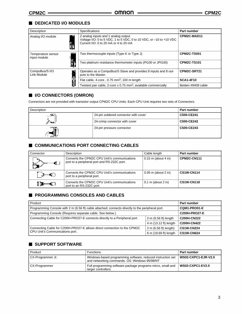
DEDICATED I/O MODULES
Description Specifications Part number
Analog I/O module 2 analog inputs and 1 analog outputVoltage I/O: 0 to 5 VDC, 1 to 5 VDC, 0 to 10 VDC, or –10 to +10 VDCCurrent I/O: 0 to 20 mA or 4 to 20 mA
CPM2C-MAD11
Temperature sensor input module
Two thermocouple inputs (Type K or Type J) CPM2C-TS001
Two platinum resistance thermometer inputs (Pt100 or JPt100) CPM2C-TS101
CompoBus/S I/O Link Module
Operates as a CompoBus/S Slave and provides 8 inputs and 8 out-puts to the Master.
CPM2C-SRT21
Flat cable, 4-core , 0.75 mm2; 100 m length SCA1-4F10
Twisted pair cable, 2-core x 0.75 mm2; available commercially Belden #9409 cable
I/O CONNECTORS (OMRON)Connectors are not provided with transistor output CPM2C CPU Units. Each CPU Unit requires two sets of Connectors.
Description Part number
24-pin soldered connector with cover C500-CE241
24-crimp connector with cover C500-CE242
24-pin pressure connector C500-CE243
COMMUNICATIONS PORT CONNECTING CABLES
Connector Description Cable length Part number
Converts the CPM2C CPU Unit’s communicationsport to a peripheral port and RS-232C port.
0.15 m (about 4 in) CPM2C-CN111
Converts the CPM2C CPU Unit’s communicationsport to a peripheral port.
0.05 m (about 2 in) CS1W-CN114
Converts the CPM2C CPU Unit’s communicationsport to an RS-232C port.
0.1 m (about 2 in) CS1W-CN118
PROGRAMMING CONSOLES AND CABLES
Product Part number
Programming Console with 2 m (6.56 ft) cable attached; connects directly to the peripheral port. CQM1-PRO01-E
Programming Console (Requires separate cable. See below.) C200H-PRO27-E
Connecting Cable for C200H-PRO27-E connects directly to a Peripheral port. 2-m (6.56 ft) length C200H-CN222
4 m (13.12 ft) length C200H-CN422
Connecting Cable for C200H-PRO27-E allows direct connection to the CPM2C 2 m (6.56 ft) length) CS1W-CN224CPU Unit’s Communications port. 6 m (19.69 ft) length CS1W-CN624
SUPPORT SOFTWARE
Product Functions Part number
CX-Programmer Jr. Windows-based programming software; reduced instruction setand networking commands. OS: Windows 95/98/NT
WS02-CXPC1-EJR-V2.0
CX-Programmer Full programming software package programs micro, small andlarger controllers.
WS02-CXPC1-EV2.0

CPM2CCPM2C
4
PERIPHERAL PORT COMMUNICATION ADAPTERS AND CONNECTING CABLES
CPM2C port Name Appearance Comments Cable length Part number
Communication RS-232CAdapter
DIN mount adapter converts theCPU’s communications port to onecommunications port and oneRS-232C DB9-pin serial port.
3.3 m (10.8 ft) CPM2C-CIF01
Converts the CPM2C CPU Unit’scommunication port to an RS-232C
2 m (6.56 ft) CS1W-CN226communication port to an RS-232Cport; for DB9-pin serial port. Can beused for program downloads.
6 m (19.7 ft) CS1W-CN626
RS-232C RS-232CCable
Program download cable from com-puter to Omron DB9-pin serial port.
2 m (6.56 ft) C200HS-CN220-EU
Communications cable to other Om- 3 m (9.8 ft) C200H-CN320-EUron devices with DB9-pin serial port. 5 m (16.4 ft) C200H-CN520-EU
Communication RS-422/RS-485Adapter
DIN mount adapter converts theCPU’s communications port to oneRS-232C DB9-pin port and oneRS-422/RS-485 port.
3.3 m (10.8 ft) CPM2C-CIF11
SCREW TERMINALS AND CONNECTING CABLES
Product Description No. of inputs/outputs Part number
Screw terminals withMIL style socket
Flat cable connector with M3 slottedscrew terminal block
20 XW2B-20G4
Flat cable connector with M3.5 screwterminal block
20 XW2B-20G5
Input screw terminalwith common forpower supply and LED indicators
Flat cable connector with M3.5 screwterminal block
16 inputsNPN input (+ common)
XW2C-20G5-IN16
Dedicated connecting 0.5 m (1.64 ft) cable length XW2Z-050Acable with one 1 m (3.28 ft) cable length XW2Z-100Aconnector for controller, one for 1.5 m (4.92 ft) cable length XW2Z-150Acontroller, one forthe screw terminal 2 m (6.56 ft) cable length XW2Z-200A
3 m (9.84 ft) cable length XW2Z-300A
5 m (16.40 ft) cable length XW2Z-500A
CPM2C CPM2C
5
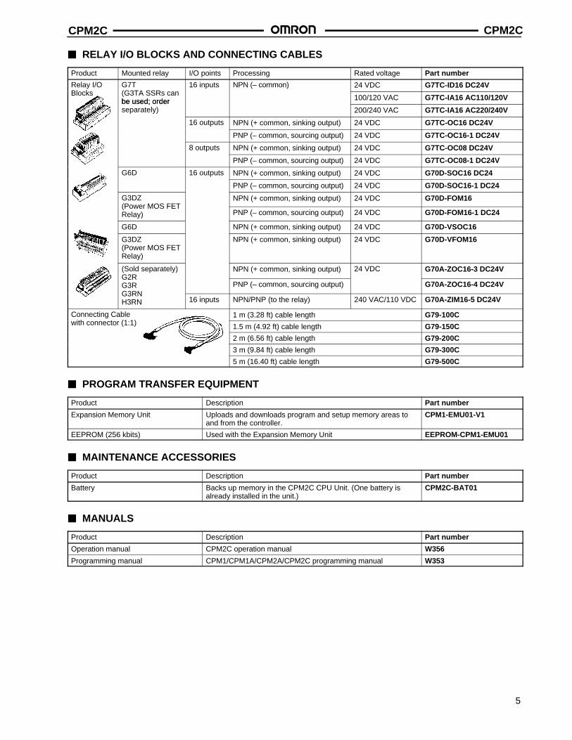
RELAY I/O BLOCKS AND CONNECTING CABLES
Product Mounted relay I/O points Processing Rated voltage Part number
Relay I/O G7T 16 inputs NPN (– common) 24 VDC G7TC-ID16 DC24VBlocks (G3TA SSRs can
be used; order 100/120 VAC G7TC-IA16 AC110/120Vbe used; orderseparately) 200/240 VAC G7TC-IA16 AC220/240V
16 outputs NPN (+ common, sinking output) 24 VDC G7TC-OC16 DC24V
PNP (– common, sourcing output) 24 VDC G7TC-OC16-1 DC24V
8 outputs NPN (+ common, sinking output) 24 VDC G7TC-OC08 DC24V
PNP (– common, sourcing output) 24 VDC G7TC-OC08-1 DC24V
G6D 16 outputs NPN (+ common, sinking output) 24 VDC G70D-SOC16 DC24
PNP (– common, sourcing output) 24 VDC G70D-SOC16-1 DC24
G3DZ NPN (+ common, sinking output) 24 VDC G70D-FOM16(Power MOS FETRelay) PNP (– common, sourcing output) 24 VDC G70D-FOM16-1 DC24
G6D NPN (+ common, sinking output) 24 VDC G70D-VSOC16
G3DZ(Power MOS FETRelay)
NPN (+ common, sinking output) 24 VDC G70D-VFOM16
(Sold separately) NPN (+ common, sinking output) 24 VDC G70A-ZOC16-3 DC24VG2RG3R PNP (– common, sourcing output) G70A-ZOC16-4 DC24VG3RNH3RN 16 inputs NPN/PNP (to the relay) 240 VAC/110 VDC G70A-ZIM16-5 DC24V
Connecting Cable 1 m (3.28 ft) cable length G79-100Cwith connector (1:1) 1.5 m (4.92 ft) cable length G79-150C
2 m (6.56 ft) cable length G79-200C
3 m (9.84 ft) cable length G79-300C
5 m (16.40 ft) cable length G79-500C
PROGRAM TRANSFER EQUIPMENT
Product Description Part number
Expansion Memory Unit Uploads and downloads program and setup memory areas toand from the controller.
CPM1-EMU01-V1
EEPROM (256 kbits) Used with the Expansion Memory Unit EEPROM-CPM1-EMU01
MAINTENANCE ACCESSORIES
Product Description Part number
Battery Backs up memory in the CPM2C CPU Unit. (One battery isalready installed in the unit.)
CPM2C-BAT01
MANUALS
Product Description Part number
Operation manual CPM2C operation manual W356
Programming manual CPM1/CPM1A/CPM2A/CPM2C programming manual W353

CPM2CCPM2C
6
Specifications GENERAL SPECIFICATIONS FOR CPU AND EXPANSION UNITS
Item CPU Units with 10/20 I/O points CPU Units with Expansion I/O Units and
Relay outputs Transistor outputs32 I/O points tran-sistor outputs
Expansion Units
Supply voltage 24 VDC
Operating voltagerange
20.4 to 26.4 VDC
Power consumption(See Note)
CPM2C-10CDR-: 4 WCPM2C-10CDTC-D: 3 WCPM2C-10CDTM-D: 3 WCPM2C-20CDR-: 4 WCPM2C-20CDTC-D: 3 WCPM2C-20CDTM-D: 3 WCPM2C-32CDTC-D: 3 WCPM2C-32CDTM-D: 3 W
Note: The above values for CPU Unit power consumptioninclude the power consumption for ProgrammingConsoles and Communications Adapter Units (CIF).
CPM2C-10EDR: 1 WCPM2C-20EDR: 2 WCPM2C-8ER: 2 WCPM2C-24EDTC: 1 WCPM2C-24EDT1C 1 WCPM2C-32EDTC: 1 WCPM2C-32EDT1C 1 WCPM2C-8EDC: 1 WCPM2C-16EDC: 1 WCPM2C-8ETC: 1 WCPM2C-8ET1C: 1 WCPM2C-16ETC: 1 WCPM2C-16ET1C: 1 WCPM2C-24EDTM: 1 WCPM2C-24EDT1M: 1 WCPM2C-32EDTM: 1 WCPM2C-32EDT1M: 1 WCPM2C-8EDM: 1 WCPM2C-16EDM: 1 WCPM2C-8ETM: 1 WCPM2C-8ET1M: 1 WCPM2C-16ETM: 1 WCPM2C-16ET1M: 1 WCPM2C-MAD11: 3.5 WCPM2C-TS001: 1.5 WCPM2C-TS101: 1.5 WCPM2C-SRT21: 1 WCPM2C-CIF21: 1 W
Inrush current 25 A max.
Insulation resistance 20 MΩ min. (at 500 VDC) between insulated circuits
Dielectric strength 2,300 VAC for 1 min (between insulated circuits)
Noise immunity Conforms to IEC61000-4-4; 2 kV (power lines)
Vibration resistance 10 to 57 Hz, 0.075-mm double amplitude, 57 to 150 Hz, acceleration: 9.8 m/s2 in X, Y, and Z directions for 80minutes each (Time coefficient; 8 minutes × coefficient factor 10 = total time 80 minutes)
Shock resistance 147 m/s2 three times each in X, Y, and Z directions
Ambient temperature Operating: 0° to 55°C (32° to 131°F)Storage: –20° to 75°C (–4° to 167°F) except for the battery
Humidity 10% to 90% (with no condensation)
Atmosphere Must be free from corrosive gas
Power interrupt time 2 ms min.
Weight 10 I/O: 200 g max.20 I/O: 250 g max.
200 g max. 200 g max. 8 and 16 inputs: 150 g8 and 16 transistor outputs 150 g8 relay outputs 200 g10 I/O (relay outputs) 200 g24 I/O (transistor outputs) 200 g32 I/O (transistor outputs) 200 gPeripheral/RS-232C Adapter 150 gRS-422/RS-232C Adapter 150 gAC power supply unit 250 gAnalog I/O, Temperature units 200 gCompoBus/S unit 150 g
Note: When calculating the total power consumption, it is necessary to include the power consumption of Programming Consoles,RS-232C Adapters and other devices.

CPM2C CPM2C
7
CPU CHARACTERISTICS
Item 10 I/O points (relay/transistor outputs)
20 I/O points(relay/transistor outputs)
32 I/O points(transistor outputs)
Control method Stored program method
I/O control method Cyclic scan with direct output (Immediate refreshing can be performed with IORF(97).)
Programming language Ladder diagram
Instruction length 1 step per instruction, 1 to 5 words per instruction
Instructions Basic instructions: 14 Special instructions: 105 instructions, 185 variations
Execution time Basic instructions: 0.64 µs (LD instruction)Special instructions: 7.8 µs (MOV instruction)
Program capacity 4,096 words
User data memory capacity 2,048 words
I/O CPU Unit only 10 points 20 points 32 pointscapacity With Expansion
I/O Modules170 points max. 180 points max. 192 points max.
Clock function Shows the year, month, day of the week, day, hour, minute, and second. (Battery backup) CPU Unitswith “C1” in the model number have a built-in clock. The 32 I/O CPU does not have a clock function.
Communications functions A CPM2C-CN111, CS1W-CN114 or CS1W-CN118 connecting cable is required to connect to theCPM2C’s communications port. The communications port can be used as both a peripheral andRS-232C port.
Peripheral port:Supports Host Link, peripheral bus, no-protocol, or Programming Console connections.
RS-232C port:Supports Host Link, no-protocol, 1:1 Slave Unit Link, 1:1 Master Unit Link, or 1:1 NT Link connections.
Memory protection HR area, AR area, program contents, read/write DM area contents, and counter values are maintainedduring power interruptions.
Memory backup Flash memory:Program, read-only DM area, and PC Setup
Memory backup:The read/write DM area, HR area, AR area, and counter values are backed up. When a battery isinstalled, its lifetime is approximately 2 years at 25°C. When a battery is not installed, the internal ca-pacitor will backup memory for 10 days at 25°C. (See Note)
Self-diagnostic functions CPU Unit failure (watchdog timer), I/O bus error, battery error, and memory failure
Program checks No END instruction, programming errors (checked when operation is started)
Basic Interrupt 2 interrupts 4 interrupts 4 interruptsinterrupts processing Shared by the external interrupt inputs (counter mode) and the quick-response inputs.
Interval timerinterrupts
1 (Scheduled Interrupt Mode or Single Interrupt Mode)
High-speed
High-speedcounter
One high-speed counter: 20 kHz single-phase or 5 kHz two-phase (linear count method)Counter interrupt: 1 (set value comparison or set-value range comparison)
counter Interrupt Inputs 2 inputs 4 inputs 4 inputs(Counter mode) Shared by the external interrupt inputs and the quick-response inputs.
Count-up interrupts: Shared by the external interrupt inputs and the quick-response inputs.
Pulse output Two points with no acceleration/deceleration, 10 Hz to 10 kHz each, and no direction control.One point with trapezoid acceleration/deceleration, 10 Hz to 10 kHz, and direction control.Two points with variable duty-ratio outputs (using PWM(––)).(Pulse outputs can be used with transistor outputs only, they cannot be used with relay outputs.)
Synchronized pulse control One point:A pulse output can be created by combining the high-speed counter with pulse outputs and multiplyingthe frequency of the input pulses from the high-speed counter by a fixed factor.(This output is possible with transistor outputs only, it cannot be used with relay outputs.)
Quick-response inputs 2 inputs 4 inputs 4 inputs
Shared by the external interrupt inputs and the interrupt inputs (counter mode).Min. input pulse width: 50 µs max.
Input time constant(ON response time = OFF response time)
Can be set for all input points.(1 ms, 2 ms, 3 ms, 5 ms, 10 ms, 20 ms, 40 ms, or 80 ms)
Note: A CPM2C-BAT01 Battery can be installed in CPU Units that are not equipped with a clock to backup the contents of the read/writeDM area, HR area, AR area, and counter values. Memory can be backed up for up to 2 years.

CPM2CCPM2C
8
I/O ALLOCATION
Input bits IR 00000 to IR 00915 (Words not used for input bits can be used for work bits.)
Output bits IR 01000 to IR 01915 (Words not used for output bits can be used for work bits.)
Work bits 928 bits: IR 02000 to IR 04915 (Words IR 020 to IR 049) and IR 20000 to IR 22715 (Words IR 200 to IR 227)
Special bits (SR area) 448 bits: SR 22800 to SR 25515
Temporary bits (TR area) 8 bits (TR0 to TR7)
Holding bits (HR area) 320 bits: HR 0000 to HR 1915 (Words HR 00 to HR 19)
Auxiliary bits (AR area) 384 bits: AR 0000 to AR 2315 (Words AR 00 to AR 23)
Link bits (LR area) 256 bits: LR 0000 to LR 1515 (Words LR 00 to LR 15)
Timers/Counters 256 timers/counters (TIM/CNT 000 to TIM/CNT 255)
1-ms timers: TMHH(––)10-ms timers: TIMH(15)100-ms timers: TIM1-s/10-s timers: TIML(––)Decrementing counters: CNTReversible counters: CNTR(12)
Data memory Read/Write: 2,048 words (DM 0000 to DM 2047)*Read-only: 456 words (DM 6144 to DM 6599)PC Setup: 56 words (DM 6600 to DM 6655)
*The Error Log is contained in DM 2000 to DM 2021.

CPM2C CPM2C
9
I/O SPECIFICATIONS
CPU Unit Input Specifications
Item Inputs Specification
10 I/O CPU 20 I/O CPU 32 I/O CPU
Input voltage All 24 VDC +10%/–15%
Input impedance IN00000 to IN00001 2.7 kΩIN00002 to IN00004 3.9 kΩ — —
IN00002 to IN00006 — 3.9 kΩ 3.9 kΩIN00005 4.7 kΩ — —
IN00007 and up — 4.7 kΩ 4.7 kΩInput current IN00000 to IN00001 8 mA typical
IN00002 to IN00004 6 mA typical — —
IN00002 to IN00006 — 6 mA typical 6 mA typical
IN00005 and up 5 mA typical — —
IN00007 and up — 5 mA typical —
IN00007 — — 5 mA typical
IN00100 to IN00107 — — 5 mA typical
ON voltage/current IN00000 to IN00001 17 VDC min., 5.0 mA
IN00002 and up 14.4 VDC min., 3.5 mA
OFF voltage/current All 5.0 VDC max., 1.1 mA
ON delay All 1 to 80 ms max. Default: 10 ms (See Note)
OFF delay All 1 to 80 ms max. Default: 10 ms (See Note)
Circuit configuration IN00000 to IN00001
1 kΩ
IN
COM
2.7 kΩ
Input LED
Inte
rnal
circ
uits
CPU Units with 10 I/Opoitns:IN00002 to IN00004
CPU Units with 20 or32 I/O points:IN00002 to IN00006
820 Ω
IN
COM
3.9 kΩ
Input LED
Inte
rnal
circ
uits
CPU Units with 10 I/Opoints: IN00005
CPU Units with 20 I/Opoints: IN00007 toIN00011
CPU Units with 32 I/Opoints: IN00007 andIN00100 to IN00107
750 Ω
IN
COM
4.7 kΩ
Input LED
Inte
rnal
circ
uits
Note: The input time constant can be set to 1, 2, 3, 5, 10, 20, 40, or 80 ms in the PLC Setup.

CPM2CCPM2C
10
High-speed Counter Inputs
The following CPU Unit input bits can be used as high-speed counter inputs. The maximum count frequency is 5 kHz in differential phasemode and 20 kHz in the other modes.
Input Function
Differential phase mode Pulse plus direction inputmode
Up/down input mode Increment mode
IN00000 A-phase pulse input Pulse input Increment pulse input Increment pulse input
IN00001 B-phase pulse input Direction input Decrement pulse input Normal input
IN00002 Z-phase pulse input or hardware reset input (IN00002 can be used as a normal input when it is not used as a high-speedcounter input.)
Note: The minimum pulse widths for inputs IN00000 (A-phase input) and IN00001 (B-phase input) are as follows:
100 µs min.
T1 T2 T3 T4 : 12.5 µs min.
Phase A
Phase B
50 µs min.
12.5 µsmin.
Pulse plus direction input mode, Up/down inputmode, Increment mode
Differential phase mode
12.5 µsmin. T1 T2 T3 T4
50 µs min.
500 µs min.
Phase Z
The minimum pulse width for input IN00002 (Z-phase input) is as follows:
Interrupt Inputs
CPM2C PLCs have inputs that can be used as interrupt inputs (interrupt input mode or counter mode) and quick-response inputs. Theminimum pulse width for these inputs is 50 µs.In CPU Units with 10 I/O points, inputs IN00003 and IN00004 can be used as interrupt inputs. In CPU Units with 20 I/O points, inputsIN00003 through IN00006 can be used as interrupt inputs.

CPM2C CPM2C
11
EXPANSION I/O MODULE INPUT SPECIFICATIONS
Item Specification
Input voltage 24 VDC +10%/–15%
Input impedance 4.7 kΩInput current 5 mA typical
ON voltage 14.4 VDC min., 3.5 mA
OFF voltage 5.0 VDC max., 1.1 mA
ON delay 1 to 80 ms max. Default: 10 ms (See note.)
OFF delay 1 to 80 ms max. Default: 10 ms (See note.)
Circuit configuration
750 Ω
IN
COM
4.7 kΩ
Input LED
Inte
rnal
circ
uits
Note: The input time constant can be set to 1, 2, 3, 5, 10, 20, 40, or 80 ms in the PLC Setup.
CPM2C OUTPUT SPECIFICATIONS (CPU UNITS AND EXPANSION I/O MODULES)
Relay Output
Item Specification
Max. switching capacity 2 A, 250 VAC (cosφ = 1)2 A, 24 VDC (4 A/common)
Min. switching capacity 10 mA, 5 VDC
Service life of relay Electrical: 150,000 operations (30-VDC resistive load)100,000 operations (240-VAC inductive load, cosφ = 0.4)
Mechanical: 20,000,000 operations
ON delay 15 ms max.
OFF delay 15 ms max.
Circuit configurationOutput LED
Internalcircuits
COM
OUT
COM
OUT

CPM2CCPM2C
12
TRANSISTOR OUTPUTS (NPN OR PNP)
For CPU Units and Expansion I/O Modules
Item Specification
Max. switching capacity CPU Units with 10 or 20 I/O points:OUT01000 to OUT01007: 40 mA/4.5 VDC to 300 mA/20.4 VDC, 300 mA (20.4 VDC to 26.4 VDC)
CPU Units with 32 I/O points:OUT01000 to OUT01007: 40 mA/4.5 VDC to 300 mA/20.4 VDC, 300 mA (20.4 VDC to 26.4 VDC)OUT01100 to OUT01107: 40 mA/4.5 VDC to 100 mA/20.4 VDC, 100 mA (20.4 VDC to 26.4 VDC)
Expansion I/O Modules:OUT0100 to OUT0107: 40 mA/4.5 VDC to 300 mA/20.4 VDC, 300 mA (20.4 VDC to 26.4 VDC)OUT0108 to OUT0115: 40 mA/4.5 VDC to 100 mA/20.4 VDC, 100 mA (20.4 VDC to 26.4 VDC)
Note: When using OUT01000 or OUT01001 as a pulse output, connect a dummy resistor as required tobring the load current bewteen 10 and 150 mA. If the load current is below 10 mA, the ON/OFFresponse time will be longer and high-speed pulses will not be output. The transistor will heat if used at 150 mA or higher, possibly damaging elements.
Min. switching capacity 0.5 mA
Max. inrush current 0.9 A for 10 ms (charging and discharging waveform)
Leakage current 0.1 mA max.
Residual voltage 0.8 V max.
ON delay OUT01000 and OUT01001: 20 µs max.OUT01002 and up: 0.1 ms max.
OFF delay OUT01000 and OUT01001: 40 µs max. for 10 to 300 mA0.1 ms max. for 0.5 to 10 mA
OUT01002 and up: 1 ms max.
Fuse 1 fuse for each 2 outputs (The fuse cannot be replaced by the user.)
Circuit configuration NPN Outputs
COM (–)
PNP Outputs
Output LED
OUT
OUT
24 VDC
0 VDC
Output LED
OUT
OUT
COM (+)
Inte
rnal
circ
uits
Inte
rnal
circ
uits

CPM2C CPM2C
13
AC POWER SUPPLY UNITThe slim, compact CPM2C-PA201 AC Power Supply Unit is the same shape as the CPM2C’s CPU Unit. It connects with a connectingcable (23 cm) provided. It can also be used for CPM1A and CPM2A CPU Units and as display power supply (wired by the user).
AC Power Supply Unit
AC Power Supply Unit
Attachedconnectingcable
Service power supply forexternal devices such assensors (24 V).
CPM2C-PA201 AC Power Supply Unit Specifications
Item Specification
Rated output 15 W
Output voltage 24 V
Output current 600 mA
Efficiency 75% min. (at rated output)
Input Rated voltage 100 to 240 VAC (85 to 264 VAC allowable voltage range)conditions Frequency 47 to 63 Hz
Current 100 V 0.4 A
200 V 0.2 A
Leakage 100 V 0.5 mA max. (at rated output)current 200 V 1 mA max. (at rated output)
Inrush 100 V 15 A max. (at 25°C cold start)current 200 V 30 A max. (at 25°C cold start)
Output Output voltage accuracy 5%/–10%, 10%/–15% (including input, load, and temperature fluctuations)characteristics Minimum output current 30 mA
Ripple noise voltage 2% (p-p) max.
Input fluctuation 0.75% max.
Load fluctuation 4% max.
Temperature fluctuation 0.05%/°C max.
Startup time 300 ms max. (at input voltage of 100 VAC or 200 VAC and the rated output)
Output hold time 10 ms (at input voltage of 100 VAC or 200 VAC and the rated output)
Overcurrent protection Self-resetting, operates at 105% to 335% of the rated current, suspended and independentoperation
Overvoltage protection None
Ambient operating temperature 0° to 55°C (32° to 131°F)
Ambient storage temperature –20° to 70°C (–4° to 158°F)
Ambient operating humidity 10% to 90% (no condensation)
Dielectric strength 2,000 V for 1 min between all inputs and GRLeakage current: 10 mA
3,000 V for 1 min between all inputs and all outputsLeakage current: 10 mA
1,000 V for 1 min between all outputs and GRLeakage current: 10 mA
Insulation resistance 100 MΩ min. at 500 VDC between all outputs and any input, and between all outputs andGR
Vibration resistance 10 to 57 Hz, amplitude, 57 to 150 Hz, acceleration: 9.8 m/s2 in X, Y, and Z directions for80 minutes according(Time coefficient: 8 minutes × coefficient factor 10 = total time 80 min.)
Shock resistance 147 m/s2 3 times each in X, Y, and Z directions
Noise terminal voltage FCC class A
Weight 250 g max.

CPM2CCPM2C
14
DEDICATED I/O MODULES SPECIFICATIONS
Mixed Analog I/O Module CPM2C-MAD11 (2 input and 1 output channels)For process input variables such as pressure, flow, and humidity,use a Mixed Analog I/O Module. The single analog output canprovide a signal for recording devices, valve controllers or atransfer output of the analog signal. Up to 4 Mixed Analog I/OModules can be used in a CPM2C system with other ExpansionI/O Modules. A maximum of 5 Expansion I/O Modules, includingDedicated I/O Modules, can be used in a CPM2C system.
3. Expansion I/Oconnector (input)
2. Input type andrange selectorDIP switch
1. Analog I/O terminals
Item Voltage I/O Current I/O
Analog Number of inputs 2 inputs (2 words allocated)input section
Input signal range 0 to 5 VDC, 1 to 5 VDC,0 to 10 VDC, or –10 to +10 VDC
0 to 20 mA or 4 to 20 mA
Max. rated input ±15 V ±30 mA
External input impedance 1 MΩ min. 250 ΩResolution 1/6000 (full scale)
Overall accuracy 25°C 0.3% full scale 0.4% full scale
0 to 55°C 0.6% full scale 0.8% full scale
A/D conversion data 16-bit binary (4-digit hexadecimal)
Full scale for –10 to +10 V: F448 to 0BB8 HexFull scale for other ranges: 0000 to 1770 Hex
Averaging function Supported (Settable for individual inputs via DIP switch)
Open-circuit detection function Supported
Analog Number of outputs 1 output (1 word allocated)outputsection
Output signal range 1 to 5 VDC, 0 to 10 VDC, or –10 to +10 VDC
0 to 20 mA or 4 to 20 mA
Allowable external output load resistance 1 kΩ min. 600 Ω max.
External output impedance 0.5 Ω max. —
Resolution 1/6000 (full scale)
Overall accuracy 25°C 0.4% full scale
0 to 55°C 0.8% full scale
Set data (D/A conversion) 16-bit binary (4-digit hexadecimal)
Full scale for –10 to +10 V: F448 to 0BB8 HexFull scale for other ranges: 0000 to 1770 Hex
Conversion time 2 ms/point (6 ms/all points)
Isolation method Photocoupler isolation between analog I/O terminals and internal circuits. Noisolation between analog I/O signals.

CPM2C CPM2C
15
Temperature Sensor Input Modules CPM2C-TS001 and CPM2C-TS101 (2 input channels)
By connecting a Temperature Sensor Module to the CPM2C, inputs can be received from thermocouples or temperature resistance ther-mometers. Inputs are converted to binary data (4-digit hexadecimal) and stored in the IR area. A maximum of four Temperature SensorInput Modules can be used in a CPM2C system.
1. Temperature input terminals
3. Temperature range rotary switch
2. Temperature scale DIP switch
Cold junction compensator
4. Expansion I/O connector (input)
CPM2C-TS001
1. Temperature input terminals
4. Expansion I/O connector (input)
CPM2C-TS101
3. Temperature range rotary switch
2. Temperature scale DIP switch
Item CPM2C-TS001 CPM2C-TS101
Temperature sensors ThermocouplesSwitchable between Types K and J, but sametype must be used for all inputs.
Platinum resistance thermometerSwitchable between Pt100 and JPt100, butsame type must be used for all inputs.
Number of inputs 2
Allocated input words 2
Max. number of modules 4 4
Temperature ranges Type K: –200° to 1300°C, 0.0° to 500.0°C–300° to 2300°F, 0.0° to 900.0°F
Type J: –100° to 850°C, 0.0° to 400.0°C–100° to 1500°F, 0.0° to 750.0°F
Both Pt100 and JPt100:–200.0° to 650.0°C–300.0° to 1200.0°F
Accuracy (See Note 2) The larger of ±0.5% of converted value or ±2°C,±1 digit max. (See Note 1)
The larger of ±0.5% of converted value or ±1°C,±1 digit max.
Conversion time 250 ms for 2 input points
Converted temperature data 16-bit binary data (4-digit hexadecimal)
Isolation Photocouplers between all temperature input signals
Note: 1. Accuracy for a K-type sensor at –100°C or less is ±4°C ±1 digit max.2. The error deviation for temperatures in °F is double that for °C.
CompoBus/S I/O Link Module CPM2C-SRT21
The CPM2C controller can function as a Slave to a CompoBus/S Master Module (or SRM1 Controller) when a CPM2C-SRT21 Compo-Bus/S I/O Link Module is connected. The CompoBus/S I/O Link Module links 8 inputs and 8 outputs between the Master Module and theCPM2C. Up to 5 Expansion I/O Modules or Expansion Modules can be connected to a CPM2C CPU Unit.
1. CompoBus/S terminals
2. DIP switch sets unit number, communicationsmode and whether or not outputs will be clearedafter a communications error.
4. Expansion I/O connector (input)
3. LED indicators
Number of I/O bits 8 input bits, 8 output bits
Max. number of connectable nodes 16
Number of words occupied inCPM2C I/O memory
1 input word, 1 output word(Allocated in the same way as other Expansion I/O Modules or Expansion Modules)
Node number setting Set using the DIP switch.
Note: See the CompoBus/S section of Omron’s Remote I/O and Wiring Solutions Catalog (GC RIO1) for more details on CompoBus/Scommunications.

CPM2CCPM2C
16
SERIAL COMMUNICATIONS MODULESCPM2C-CIF01 Peripheral and RS-232C Adapter Module
CPM2C-CIF01
Peripheral port
RS-232C port(D-sub 9-pinconnector)
Communications port
CPM2CCPU Unit
CPM2C-CIF11 RS-232 and RS-422/RS-485 Adapter Module
CPM2C-CIF11
RS-422/485port (terminalblock)
RS-232C port(D-sub 9-pinconnector)
CPM2C CPU Unit
Communications port
Internal Configuration
CPM2C-CIF01 CPM2C CPU Unit
Peripheral port(CMOS/RS-232C)
RS-232Cport(RS-232C)
CMOS level → RS-232C conversion
Peripheral port(CMOS level)
RS-232C port(RS-232C)
CMOS level
CPM2C-CIF11 CPM2C CPU Unit
RS-422/RS-485 port
RS-232C port
CMOS level → RS-422 conversion
Peripheral port(CMOS level)
RS-232C port
Note: The signal levels for the peripheral port will change auto-matically with the connecting cable used. For example, ifa connecting cable from a Programming Console is con-nected, the signal level will switch to CMOS level,whereas if the CS1W-CN26 Connecting Cable for apersonal computer is connected, the signal level willswitch to RS-232C.
Note: A Programming Console cannot be connected to theRS-422/485 port.
CPM2C-CIF01/CIF11 Specifications
Item Specification
CPM2C-CIF01 CPM2C-CIF11
Upper port Signal conversion
Outputs signals from the CPU Unit’s CMOS inter-face without conversion, or converts CMOS level(CPU Unit side) to RS-232C (connected deviceside).
Converts CMOS level (CPU Unit side) toRS-422/RS-485 (connected device side).RS-422/RS-485 (externally connected device) insu-lated using DC/DC converter or photocoupler.
Function Host Link, peripheral bus, no-protocol, or Pro-gramming Console connections.
Host Link, peripheral bus, or no-protocol connec-tions.
Lower port Signal conversion
Outputs signals from the CPU Unit’s CMOS inter-face without conversion.
Outputs signals from the CPU Unit’s CMOS inter-face without conversion.
Function Host Link, no-protocol, 1:1 Link, or 1:1 NT Linkconnections.
Host Link, no-protocol, 1:1 Link, or 1:1 NT Link con-nections.
Power supply Power supplied from CPU Unit.
Current consumption 0.3 A max. at 5 V
Weight 150 g max.
Note: Neither the CPM2C-CIF01 nor the CPM2C-CIF11 can be used with any PC other than the CPM2C. A CPM2C-CIF11 or anotherCPM2C-CIF01 cannot be connected to the CPM2C if a CPM2C-CIF01 is already connected to it.

CPM2C CPM2C
17
DimensionsUnit: mm (inch)
CPU UNITS
CPU Units with Relay Outputs(CPM2C-10CDR-D, CPM2C-10C1DR-DCPM2C-20CDR-D, CPM2C-20C1DR-D)
CPU Units with Transistor Outputs(CPM2C-10/20/32CDTC-D, CPM2C-10/20/32C1DTC-D,CPM2C-10/20CDT1C-D, CPM2C-10/20C1DT1C-D)
90(3.54)
90(3.54)
33 (1.30) 33 (1.30)65 (2.56) 65 (2.56)
EXPANSION I/O MODULES
Modules with Relay Outputs(CPM2C-8ER, CPM2C-10EDR)
Modules with Transistor Outputs(CPM2C-24EDTC, CPM2C-24EDT1C)
Modules with Transistor Outputs Only and Modules with Inputs Only(CPM2C-8EDC, CPM2C-8ETC, CPM2C-8ET1C,CPM2C-16EDC, CPM2C-16ETC, CPM2C-16ET1C)
90(3.54)
90(3.54)
33 (1.30) 33 (1.30)65 (2.56) 65 (2.56)
90(3.54)
65 (2.56)
20(0.79)
Modules with 20 Relay I/O(CPM2C-20EDR-D)
90(3.54)
33 (1.30) 65 (2.56)

CPM2CCPM2C
18
Unit: mm (inch)
AC Power Supply Unit(CPM2C-PA201)
Peripheral/RS-232C Adapter Module(CPM2C-CIF01)
RS-232C and RS-422/RS-485 Adapter Module(CPM2C-CIF11)
90(3.54)
90(3.54)
33 (1.30)
40(1.57)
65 (2.56)
03.54)
65 (2.56)33(1.30)
65 (2.56)33(1.30)
DEDICATED I/O MODULES
CPM2C-MAD11 Analog I/O Module
90(3.54)
65 (2.56)
33(1.30)
CPM2C-TS001, CPM2C-TS101Temperature Sensor Modules
90(3.54)
65 (2.56)
33(1.30)

CPM2C CPM2C
19
90(3.54)
65 (2.56)
20(0.79)
CPM2C-SRT21 CompoBus/S I/O Link Module
CPM2C MODULES WITH CONNECTORS ATTACHED
Modules with Relay Outputs Modules with Transistor Outputs(Using pressure connectors)
Modules with Transistor Outputs(Using soldered connectors)
104 (4.09) 111 (4.37)
74 (2.91)
104 (4.09)
FunctionsThe CPM2C programmable controllers offer a variety of featuresin a compact Unit, including synchronized pulse control, interruptinputs, pulse outputs, and a clock function. The CPM2C CPUUnit can handle a broad range of machine control applicationsand it is small enough to be incorporated as the control unit inalmost any free-standing machine.
The full complement of communications functions lets youcommunicate with personal computers, other OMRON PLCs, andOMRON Programmable Terminals. These communicationscapabilities allow the user to design a low-cost, effective controlsystem.
The communications port can be usedsimultaneously as two ports: Peripheraland RS-232C. The peripheral port sup-ports Programming Devices, Host Link,and no-protocol communications. TheRS-232C port supports Host Link, no-pro-tocol (serial), 1:1 Link, and 1:1 NT Linkcommunications.
CPU Units with 10 or 20 I/O points (relay or tran-sistor outputs) and 32 I/O points (transistor onlyare available. Expansion I/O Units can be con-nected to increase capacity to 192 I/O points.

CPM2CCPM2C
20
TIME-PROPORTIONAL CONTROLThe CPM2C performs simple-to-program, time-proportionalcontrol using up to four Analog I/O modules (maximum 8 analoginputs and 4 analog outputs) and the PID and PWM expansioninstructions. These instructions set the parameters for PIDcontrol and a pulse output with variable duty ratio. For increasedreliability, an open-circuit detection function can be used with the1 to 5 VDC and 4 to 20 mA analog input settings.
For temperature monitoring applications, CPM2C accepts up to 8inputs (two per module) from Temperature Sensor Inputmodules. The PID instruction can manipulate the input fromeither thermocouple or platinum resistance thermometer sensors.
DISTRIBUTED I/O CONTROL
Omron’s CompoBus/S I/O Link provides distributed CPU controlbased on a “PLC + compact PLC” configuration which providesimprovements over distributed control based on “PLC + remoteI/O” configurations. The distributed CPU control makesequipment module, so designs can be standardized, specialneeds can be addressed and modules can be replaced easily inthe event of breakdown without affecting the main CPU.
MasterPLC
CompoBus/S Master Module(or SRM1 PLC)
CPM2C(Slave)
CompoBus/S I/O Link Module
CompoBus/S
Distributed CPU control
BUILT-IN MOTOR CONTROL CAPABILITYSynchronized Pulse Control (Transistor Output Models Only)Synchronized pulse control provides an easy way to synchronizethe operation of a peripheral piece of equipment with the mainequipment. The output pulse frequency can be controlled assome multiple of the input pulse frequency, allowing the speed ofa peripheral piece of equipment (such as a supply conveyor) tobe synchronized with the speed of the main piece of equipment.
Encoder
CPM2C
Motor driver Motor
Pulses are output as a fixed multiple of the input frequency.
HIGH-SPEED COUNTERS AND INTERRUPTSThe CPM2C has up to four high-speed counter inputs. The onehigh-speed counter input has a response frequency of 20 kHz/5 kHz, and the four interrupt inputs (in counter mode)have a response frequency of 2 kHz.
Four Input ModesThe high-speed counter can be used in any one of the four inputmodes: differential phase mode (5 kHz), pulse plus directioninput mode (20 kHz), up/down pulse mode (20 kHz), or incrementmode (20 kHz). Interrupts can be triggered when the countmatches a set value or falls within a specified range.
Interrupt InputsThe interrupt inputs (counter mode) can be used for incrementingcounters or decrementing counters (2 kHz) and trigger aninterrupt (executing the interrupt program) when the countmatches the target value. Use this for target-value comparison orrange comparison control that is unaffected by the cycle time.
Easy Position Control with Pulse Outputs (transistor output models only)The CPM2C PLCs with transistor outputs have two outputs thatcan produce 10 Hz to 10 kHz pulses (single-phase outputs).
When used as single-phase pulse outputs, there can be twooutputs with a frequency range of 10 Hz to 10 kHz with a fixedduty ratio or 0.1 to 999.9 Hz with a variable duty ratio (0 to 100%duty ratio).
When used as pulse plus direction or up/down pulse outputs,there can be just one output with a frequency range of 10 Hz to10 kHz.
Counter inputs
Resets inputs (for differentialphase inputs)
Sensor
Rotary encoder(such asE6C2-C)
Input Responsefrequency
Input mode (count value) Controlmethod
0000000001
5 kHz Differential phase input mode(-8,388,608 to 8,388,607)
Targetvalue
0000220 kHz Pulse + direction input mode
(-8,388,608 to 8,388,607)Up/down pulse input mode (-8,388,608 to 8,388,607)Increment mode (0 to 16,777,215)
compari-son inter-rupts
Rangecompari-son inter-rupts

CPM2C CPM2C
21
PULSE OUTPUTS (TRANSISTOR OUTPUT MODELS ONLY)The CPM2C has two pulse outputs. You can configure these outputs as two single-phase outputs without acceleration and deceleration,two variable duty-ratio pulse outputs, or pulse outputs with trapezoidal acceleration/deceleration (one pulse + direction output and oneup/down pulse output). The pulse output’s PV coordinate system can also be specified in the PLC Setup as either relative or absolute.
Stepping motor
Pulse outputs
Motor con-troller
CPM2Ccontroller
X-Y positioning table
Item Single-phase pulse output without
Variable duty-ratiopulse output
Single-phase pulse output with trapezoidal acceleration/deceleration
acceleration/deceleration Pulse + direction output Up/down pulse output
Controlling instruction(s) PULS(65) and SPED(64) PWM(––) PULS(65) and ACC(––)
Outputnumber
01000 Pulse output 0 (See Note.)
Pulse output 0 (See Note.)
Pulseoutput 0
Pulse output Pulseoutput 0
CW pulse output
01001 Pulse output 1 (See Note.)
Pulse output 1 (See Note.)
Direction output CCW pulse output
Output frequency range 10 Hz to 10 kHz 0.1 Hz to 999.9 Hz 10 Hz to 10 kHz 10 Hz to 10 kHz
Pitch 10 Hz 0.1 Hz 10 Hz 10 Hz
Duty ratio 50% 0 to 100% 50% 50%
Note: With single-phase pulse outputs, pulse outputs 0 and 1 can each be output independently.
Application Example: Adjusting Film/Paper Web Speed in Packaging and Printing
CPM2C controller
Main Motor
Encoder
SYSDRIVE Inverter
W-Series Servo Motor/Servo Drive

CPM2CCPM2C
22
HIGH-SPEED INPUT CAPABILITIES FORMACHINE CONTROL
High-speed Interrupt Input FunctionThe 20- and 32-point CPU Units have 4 inputs that can be usedas interrupt inputs and the 10-point CPU Units have 2 inputs thatcan be used as interrupt inputs. These inputs are shared withquick-response inputs and interrupt inputs in counter mode andhave a minimum input signal width of 50 µs and response time of0.3 ms. When an interrupt input goes ON, the main program isstopped and the interrupt program is executed.
Quick-response Input FunctionRegardless of the cycle time, the 20-point CPU Units have 4inputs that can be used as quick-response inputs and the10-point CPU Units have 2 inputs that can be used asquick-response inputs. These inputs are shared with interruptinputs and interrupt inputs in counter mode; they can reliablyread input signals with a signal width as short as 50 µs.
Stabilizing Input Filter FunctionThe input time constant for all inputs can be set to 1 ms, 2 ms,3 ms, 5 ms, 10 ms, 20 ms, 40 ms, or 80 ms. The effects ofchattering and external noise can be reduced by increasing theinput time constant.
OTHER FUNCTIONS
Analog SettingsThere are two controls on the CPU Unit that can be turned tochange the analog settings (0 to 200 BCD) of timers andcounters. These controls can be used to easily change orfine-tune machine settings such as a conveyor belt’s pause timeor feed rate.
Calendar/ClockThe CPU Units with a built-in clock (accuracy within 1minute/month) can be read from the program to show the currentyear, month, day, day of the week, and time. The clock can beset from a programming device (such as a ProgrammingConsole) or the time can be adjusted by rounding up or down tothe nearest minute.
Long-term TimerThe long-term timer provides an easy way to control equipmentscheduling. Use two instructions to set this up. The long-termtimer instruction (TIML) lets you set values up to 99,990 seconds(27 hours, 46 minutes, 30 seconds) and the Seconds-to-Hoursconversion instruction (HMS) lets you schedule this with otherclock functions.

CPM2C CPM2C
23
CONFIGURATION USING I/O RELAY BLOCKS AND SCREW TERMINALSLightly shaded connections are Inputs; darkly shaded connections are outputs in the diagram below.
Outputs Inputs
Cables (See note.)XW2Z-050A (0.5 m)XW2Z-100A (1 m)XW2Z-150A (1.5 m)XW2Z-200A (2 m)XW2Z-300A (3 m)XW2Z-500A (5 m)
Screw TerminalsXW2B-20G4 (M3 screws)XW2B-20G5 (M3.5 screws)
Cables (See note.)
Relay Input BlocksG7TC-ID16, G7TC-IA16
Cables (See note.)
Screw TerminalsXW2B-20G4 (M3 screws)XW2B-20G5 (M3.5 screws)
Cables
Relay Output TerminalsG70D-OC16, G70D-OC16-1G70D-SOC16, G70D-SOC16-1G70D-FOM16, G70D-FOM16-1
CablesG79-CG2R-1-S(N)
Relay Output TerminalsG7TC-OC08
Relay Output TerminalsG70A-ZOC16-3G70A-ZOC16-4
Note: The allowable current for theXW2Z-A is 1 A. Do not allowthe current on the common terminalto exceed 1 A.
CablesG79-100C (1 m)G79-150C (1.5 m)G79-200C (2 m)G79-300C (3 m)G79-500C (5 m)
Input Screw TerminalXW2C-20G5-IN16 (M3.5 screws)
XW2Z-050A (0.5 m)XW2Z-100A (1 m)XW2Z-150A (1.5 m)XW2Z-200A (2 m)XW2Z-300A (3 m)XW2Z-500A (5 m)
XW2Z-050A (0.5 m)XW2Z-100A (1 m)XW2Z-150A (1.5 m)XW2Z-200A (2 m)XW2Z-300A (3 m)XW2Z-500A (5 m)
G79-100C (1 m)G79-150C (1.5 m)G79-200C (2 m)G79-300C (3 m)G79-500C (5 m)

CPM2CCPM2C
24
Communications
NT LINK FOR PROGRAMMABLE TERMINALSThe CPM2C can be connected directly to an OMRON NT-Series Programmable Terminal in NT Link mode (1:1) for high-speed transmis-sion of data. No separate drivers are required. Use the communications port for the NT Link connection.
There are two ways to configure NT Link depending on the communications port’s setting for single or dual transmission (host link style).For single transmission, use a C200H-CN20-EU cable and a D-sub 9-pin adapter (either CPM2C-CN111 or CS1W-CN118) to connectat the communications port. For dual transmission when the communications port may be used for two different purposes, connect the Programmable Terminal with aC200H-CN320-EU cable to the D-sub 9-pin connector on the CPM2C-CIF01 Communications Adapter. For RS-422 NT Link, configure acustom cable following the pinout shown in Programmable Terminal manual for the model selected, then connect it to the RS-422 termi-nals on the CPM2C-CIF11 Communications Adapter.
Connecting CableC200H-CN320-EU (3 m)C200H-CN520-EU (5 m)
CPM2C-CN111 (0.15 m)
CS1W-CN118 (0.1 m)
CPM2CCPU Unit
Programmable Terminal
RS-232C port(D-sub 9-pin)
Communicationsport
Communications port
RS-232C port(D-sub 9-pin)
CPM2C-CIF01
RS-422/RS-485 ← Peripheral port
CPM2C-CIF11
RS-232C connection
NT Link
Host Link
Connecting CableC200H-CN320-EU (3 m)C200H-CN520-EU (5 m)
Connecting CableRefer to RS-422 connection based on the Program-mable Terminal model.
Note: The Programmable Terminal cannot be connected using a pe-ripheral port connection when communicating via an NT Link.

CPM2C CPM2C
25
HOST LINK
1:1 Connection
Use one of the connecting cables shown in the following diagram to connect a personal computer with Support Software to the CPM2C’scommunications port for 1:1 Host Link communications or no-protocol (serial) communications.
A personal computer can be connected to the CPU Unit’scommunications port with an C200HS-CN220-EU cable and CS1W-CN118adapter or CS1W-CN26-EU for program downloads. The cable has D-sub 9-pin connector.
RS-232C port (D-sub 9-pin)
CPM2C CPU Unit
CPM2C-CN111(0.15 m)
Connecting CableC200HS-CN220-EU(2 m) CS1W-CN118 (0.1 m)
IBM PC/AT orcompatible computer
CPM2C-CIF01
CPM2C-CIF11
Connecting CableCS1W-CN226-EU (2 m)CS1W-CN626-EU (6 m)
Note: Refer to Section 4 Using Programming Devices in the CPM2C Operation Manual (W356) for details on theSupport Software that can be used with the CPM2C.
RS-232C(D-sub 9-pin)
RS-422/RS-485

CPM2CCPM2C
26
1:N Connection
Up to 32 Omron PLCs, including CPM2C PLCs, can be connected to a host computer. The total length of an RS-422/RS-485 system is500 m max.
CPM2CCPU Unit
CPM2C-CIF11
When using the port as an RS-422/RS-485 port
Up to 32 programmable controllers
CPM2CCPU Unit
CPM2C-CIF11
CPM2CCPU Unit
CPM2C-CIF11
IBM PC/AT or compatible computer with RS-422/RS-485
Note: Be sure that the power supply requirements of the CPU Unit, Expansion Modules, and Expansion I/O Modules do not exceed theavailable capacity.
NO-PROTOCOL COMMUNICATIONSThe transmit TXD(48) and receive RXD(47) instructions can be used in no-protocol mode to exchange data with standard serial devices.For example, data can be received from a bar code reader or transmitted to a serial printer. The serial devices can be connected to thecommunications port as a RS-232C port or peripheral port, as shown in the following diagrams. Some adapter cables may be required.
CPM2C CPU UnitRS-232C port
Bar code reader Serial printer Modem Other serial devices
Note: See One-to-one Computer Connections inOperation Manual (W356) for details on thesystem configurations that can be as-sembled for serial communications.

CPM2C CPM2C
27
1:1 LINK CONNECTIONS FOR DATA EXCHANGEA CPM2C can be linked to another CPM2C, a CQM1, CPM1, CPM1A, CPM2A, SRM1(-V2), C200HS, or C200HX/HE/HG controller. TheCPM2C must be connected using the communications port as an RS-232C port (not as a peripheral port).
CPM2C-CN111 (0.1 m)
CS1W-CN118 (0.1 m) CS1W-CN118 (0.1 m)
1:1 Link Master CPM2C CPU Unit
Connecting CableC200H-CN320-EU (3 m)C200H-CN520-EU (5 m)
RS-232C port (D-sub 9-pin)
CPM2C-CN111 (0.1 m)
RS-232C port (D-sub 9-pin)1:1 Link Slave CPM2C CPU Unit
Omron PLC (CQM1H, CPM1, CPM1A, CPM2A,SRM1(-V2), C200HS, or C200HX/HE/HG)
Omron PLC (CQM1H, CPM1, CPM1A, CPM2A,SRM1(-V2), C200HS, or C200HX/HE/HG)
CPM2C-CIF01
CPM2C-CIF11
CPM2C-CIF01
CPM2C-CIF11
Link bits
WRITE area
READ area
LR 00
LR 07LR 08
LR 15
WRITE
READ
READ area
WRITE area
LR 00
LR 07LR 08
LR 15
READ
WRITE
Link bits
Note: Even though the peripheral port on the CPM2C-CIF01 can output RS-232C, this port cannot be used for one-to-one link communications.

CPM2CCPM2C
28
COMPOBUS/S I/O LINK CONNECTIONSA CompoBus/S I/O Link can be used to create an I/O link (remote I/O) of 8 input points and 8 output points with a CompoBus/S MasterModule or SRM1 controller. The connection is made through a CompoBus/S I/O Link Module.
From the standpoint of the CPM2C CPU Unit, the area allocated to the CompoBus/S I/O Link Module can be treated just like the areaallocated to an Expansion I/O Module. The difference is that the bits are not actual I/O points, but I/O bits in the Master Module.
CPM2C CPU Unit
CompoBus/S Master Module (or SRM1 PLC)
CompoBus/S I/O LinkModule (Slave)
Cables
Use SCA1-4F10 flat cable or twisted pair cable to connect the nodes in the CompoBus/S I/O Link. (The flat cables and twisted pair cablescannot be combined in the same system.)
Description Model Specifications
Flat cable SCA1-4F10 4-core flat cable, 0.75 mm2; 100 m length
Twisted pair cable Belden #9409 cable 2-core x 0.75 mm2; available commercially
PROGRAM TRANSFER UNITUse Omron’s EEPROM program transfer unit to update programs in machines or program multiple controllers with the same program.The CPM1-EMU01-V1 Expansion Memory Unit connects to the peripheral port of micro and small PLCs.
Expansion Memory Unit
Indicator
UPLOAD+DM Button UPLOAD Button
EEPROM
CPM2C-CN111
CS1W-CN114
CPM2C
CPM2CCPM2C-CIF01

CPM2C CPM2C
29
Instruction Set
SEQUENCE INSTRUCTIONS
Sequence Input Instructions
Instruction Mnemonic Code
LOAD LD
LOAD NOT LD NOT
AND AND
AND NOT AND NOT
OR OR
OR NOT OR NOT
AND LOAD AND LD
OR LOAD OR LD
Sequence Output Instructions
Instruction Mnemonic Code
OUTPUT OUT
OUT NOT OUT NOT
SET SET
RESET RSET
KEEP KEEP 11
DIFFERENTIATE UP DIFU 13
DIFFERENTIATE DOWN DIFD 14
Sequence Control Instructions
Instruction Mnemonic Code
NO OPERATION NOP 00
END END 01
INTERLOCK IL 02
INTERLOCK CLEAR ILC 03
JUMP JMP 04
JUMP END JME 05
TIMER/COUNTER INSTRUCTIONS
Instruction Mnemonic Code
TIMER TIM
COUNTER CNT
REVERSIBLE COUNTER CNTR 12
HIGH-SPEED TIMER TIMH 15
COMPARISON INSTRUCTIONS
Instruction Mnemonic Code
COMPARE CMP 20
TABLE COMPARE TCMP(@) 85
DOUBLE COMPARE CMPL(@)† 60
BLOCK COMPARE BCMP(@)† 68
AREA RANGE COMPARE ZCP ––
DOUBLE AREA RANGE COMPARE ZCPL ––
DATA MOVEMENT INSTRUCTIONSInstruction Mnemonic Code
MOVE MOV(@) 21
MOVE NOT MVN(@) 22
BLOCK TRANSFER XFER(@) 70
BLOCK SET BSET(@) 71
DATA EXCHANGE XCHG(@) 73
SINGLE WORD DISTRIBUTE DIST(@) 80
DATA COLLECT COLL(@) 81
MOVE BIT MOVB(@) 82
MOVE DIGIT MOVD(@) 83
SHIFT INSTRUCTIONSInstruction Mnemonic Code
SHIFT REGISTER SFT /10
WORD SHIFT WSFT(@) 16
ASYNCHRONOUS SHIFT REGISTER ASFT(@)† 17
ARITHMETIC SHIFT LEFT ASL(@) 25
ARITHMETIC SHIFT RIGHT ASR(@) 26
ROTATE LEFT ROL(@) 27
ROTATE RIGHT ROR(@) 28
ONE DIGIT SHIFT LEFT SLD(@) 74
ONE DIGIT SHIFT RIGHT SRD(@) 75
REVERSIBLE SHIFT REGISTER SFTR(@) 84
INCREMENT/DECREMENT
Instruction Mnemonic Code
INCREMENT INC(@) 38
DECREMENT DEC(@) 39
CALCULATION INSTRUCTIONSInstruction Mnemonic Code
BCD ADD ADD(@) 3O
BCD SUBTRACT SUB(@) 31
BCD MULTIPLY MUL(@) 32
BCD DIVIDE DIV(@) 33
BINARY ADD ADB(@) 50
BINARY SUBTRACT SBB(@) 51
BINARY MULTIPLY MLB(@) 52
BINARY DIVIDE DVB(@) 53
DOUBLE BCD ADD ADDL(@) 54
DOUBLE BCD SUBTRACT SUBL(@) 55
DOUBLE BCD MULTIPLY MULL(@) 56
DOUBLE BCD DIVIDE DIVL(@) 57
BIT COUNTER BCNT(@)† 67
Note: : Instruction keys allocated to the Programming Console.(@): Instruction can be differentiated using input rise time to execute the instruction in just one cycle.––: Identifies an expansion instruction.†: Identifies an expansion instruction assigned a default code.
CPM2CCPM2C
30
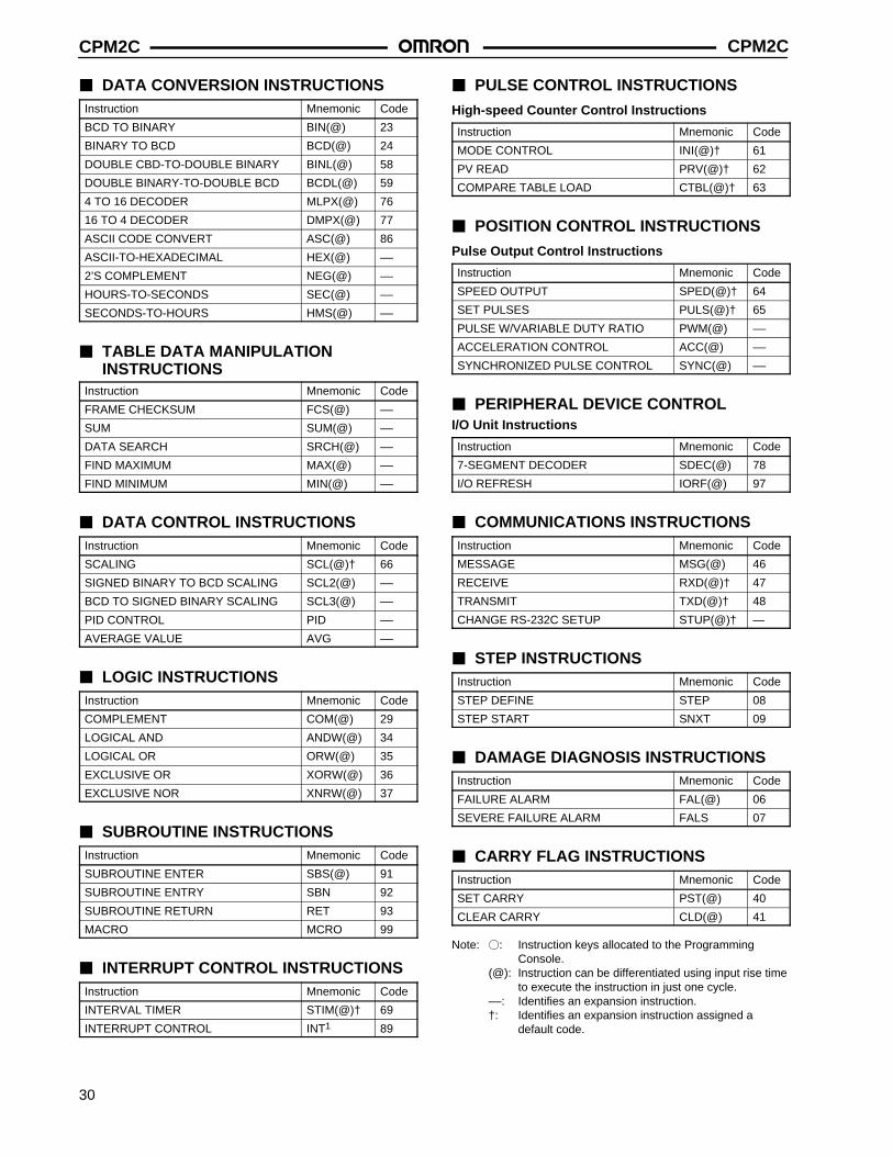
DATA CONVERSION INSTRUCTIONSInstruction Mnemonic Code
BCD TO BINARY BIN(@) 23
BINARY TO BCD BCD(@) 24
DOUBLE CBD-TO-DOUBLE BINARY BINL(@) 58
DOUBLE BINARY-TO-DOUBLE BCD BCDL(@) 59
4 TO 16 DECODER MLPX(@) 76
16 TO 4 DECODER DMPX(@) 77
ASCII CODE CONVERT ASC(@) 86
ASCII-TO-HEXADECIMAL HEX(@) ––
2’S COMPLEMENT NEG(@) ––
HOURS-TO-SECONDS SEC(@) ––
SECONDS-TO-HOURS HMS(@) ––
TABLE DATA MANIPULATION INSTRUCTIONS
Instruction Mnemonic Code
FRAME CHECKSUM FCS(@) ––
SUM SUM(@) ––
DATA SEARCH SRCH(@) ––
FIND MAXIMUM MAX(@) ––
FIND MINIMUM MIN(@) ––
DATA CONTROL INSTRUCTIONSInstruction Mnemonic Code
SCALING SCL(@)† 66
SIGNED BINARY TO BCD SCALING SCL2(@) ––
BCD TO SIGNED BINARY SCALING SCL3(@) ––
PID CONTROL PID ––
AVERAGE VALUE AVG ––
LOGIC INSTRUCTIONSInstruction Mnemonic Code
COMPLEMENT COM(@) 29
LOGICAL AND ANDW(@) 34
LOGICAL OR ORW(@) 35
EXCLUSIVE OR XORW(@) 36
EXCLUSIVE NOR XNRW(@) 37
SUBROUTINE INSTRUCTIONSInstruction Mnemonic Code
SUBROUTINE ENTER SBS(@) 91
SUBROUTINE ENTRY SBN 92
SUBROUTINE RETURN RET 93
MACRO MCRO 99
INTERRUPT CONTROL INSTRUCTIONSInstruction Mnemonic Code
INTERVAL TIMER STIM(@)† 69
INTERRUPT CONTROL INT1 89
PULSE CONTROL INSTRUCTIONS
High-speed Counter Control Instructions
Instruction Mnemonic Code
MODE CONTROL INI(@)† 61
PV READ PRV(@)† 62
COMPARE TABLE LOAD CTBL(@)† 63
POSITION CONTROL INSTRUCTIONS
Pulse Output Control Instructions
Instruction Mnemonic Code
SPEED OUTPUT SPED(@)† 64
SET PULSES PULS(@)† 65
PULSE W/VARIABLE DUTY RATIO PWM(@) ––
ACCELERATION CONTROL ACC(@) ––
SYNCHRONIZED PULSE CONTROL SYNC(@) ––
PERIPHERAL DEVICE CONTROLI/O Unit Instructions
Instruction Mnemonic Code
7-SEGMENT DECODER SDEC(@) 78
I/O REFRESH IORF(@) 97
COMMUNICATIONS INSTRUCTIONSInstruction Mnemonic Code
MESSAGE MSG(@) 46
RECEIVE RXD(@)† 47
TRANSMIT TXD(@)† 48
CHANGE RS-232C SETUP STUP(@)† —
STEP INSTRUCTIONSInstruction Mnemonic Code
STEP DEFINE STEP 08
STEP START SNXT 09
DAMAGE DIAGNOSIS INSTRUCTIONSInstruction Mnemonic Code
FAILURE ALARM FAL(@) 06
SEVERE FAILURE ALARM FALS 07
CARRY FLAG INSTRUCTIONSInstruction Mnemonic Code
SET CARRY PST(@) 40
CLEAR CARRY CLD(@) 41
Note: : Instruction keys allocated to the Programming Console.
(@): Instruction can be differentiated using input rise timeto execute the instruction in just one cycle.
––: Identifies an expansion instruction.†: Identifies an expansion instruction assigned a
default code.

CPM2C CPM2C
31
FUNCTION CODE SUMMARYThe following table lists the CPM2C instructions that have fixedfunction codes. Each instruction is listed by mnemonic and byinstruction name. Use the numbers in the leftmost column as theleft digit and the number in the column heading as the right digitof the function code.
The shaded areas are function codes to which expansioninstructions are allocated by default or to which the user canallocate expansion instructions. The expansion instructions in thebottom table are available in addition to the ones listed withdefault function codes.
Left Right digitdigit 0 1 2 3 4 5 6 7 8 9
0 NOPNo operation
ENDEnd
ILInterlock
ILCInterlockclear
JMPJump
JMEJump end
FAL(@)Failurealarm andreset
FALSSeverefailurealarm
STEPStep define
SNXTStep start
1 SFTShift register
KEEPKeep
CNTRReversiblecounter
DIFUDifferenti-ate up
DIFDDifferenti-ate down
TIMHHigh-speed timer
WSFT(@)Word shift
ASFT(@)Asynchro-nous shiftregister
--- ---
2 CMPCompare
MOV(@)Move
MVN(@) Move not
BIN(@) BCD tobinary
BCD(@) Binary toBCD
ASL(@) Shift left
ASR(@) Shift right
ROL(@) Rotate left
ROR(@) Rotateright
COM(@) Comple-ment
3 ADD(@) BCD add
SUB(@) BCD subtract
MUL(@) BCD multiply
DIV(@) BCD divide
ANDW(@) LogicalAND
ORW(@) LogicalOR
XORW(@)ExclusiveOR
XNRW(@) ExclusiveNOR
INC(@) Increment
DEC(@) Decre-ment
4 STC(@) Set carry
CLC(@) Clearcarry
--- --- --- --- MSG(@) Messagedisplay
RXD(@) Receive
TXD(@) Transmit
---
5 ADB(@) Binaryadd
SBB(@) Binarysubtract
MLB(@) Binary multiply
DVB(@) Binary divide
ADDL(@)DoubleBCD add
SUBL(@) DoubleBCD subtract
MULL(@) DoubleBCD multiply
DIVL(@) DoubleBCD divide
BINL(@) DoubleBCD-to-doublebinary
BCDL(@) Doublebinary-to-doubleBCD
6 CMPLDoublecompare
INI(@) Modecontrol
PRV(@) High-speedcounter PVread
CTBL(@) Compari-son tableload
SPED(@) Speedoutput
PULS(@) Set pulses
SCL(@) Scaling
BCNT(@)Bit counter
BCMP(@)Clockcompare
STIM(@) Intervaltimer
7 XFER(@)Blocktransfer
BSET(@)Block set
--- XCHG(@)Data exchange
SLD(@) One digitshift left
SRD(@) One digitshift right
MLPX(@) 4-to-16 decoder
DMPX(@)16-to-4 encoder
SDEC(@)7-segmentdecoder
---
8 DIST(@) Singleword distribute
COLL(@)Data collect
MOVB(@) Move bit
MOVD(@)Move digit
SFTR(@) Revers-ible shiftregister
TCMP(@) Table compare
ASC(@) ASCII convert
--- --- INT(@) Interruptcontrol
9 --- SBS(@) Subrou-tine entry
SBNSubroutinedefine
RETSubrou-tine return
--- --- --- IORF(@) I/O refresh
--- MCRO(@)Macro
Expansion Instructions Without Default Codes
Mnemonic Name Mnemonic Name
ACC(@) ACCELERATION CONTROL SCL3(@) BCD TO SIGNED BINARY SCALING
AVG AVERAGE VALUE SEC(@) HOURS TO SECONDS
FCS(@) FRAME CHECK SUM CALCULATE SRCH(@) DATA SEARCH
HEX(@) ASCII-TO-HEXADECIMAL STUP(@) CHANGE RS-232C SETUP
HMS(@) SECONDS TO HOURS SUM(@) SUM CALCULATE
MAX(@) FIND MAXIMUM SYNC SYNCHRONIZED PULSE CONTROL
MIN(@) FIND MINIMUM TIML LONG TIMER
NEG(@) 2’S COMPLEMENT TMHH VERY HIGH-SPEED TIMER
PID PID CONTROL ZCP AREA RANGE COMPARE
PWM(@) PULSE WITH VARIABLE DUTY RATIO ZCPL DOUBLE AREA RANGE COMPARE
SCL2(@) SIGNED BINARY TO BCD SCALING

CPM2CCPM2C
32Cat. No. GC MSPLC1 03/01 Specifications subject to change without notice. Printed in U.S.A.
OMRON ELECTRONICS LLCOne East Commerce DriveSchaumburg, IL 60173
NOTE: DIMENSIONS SHOWN ARE IN MILLIMETERS. To convert millimeters to inches divide by 25.4.
1-800-55-OMRON
OMRON CANADA, INC.885 Milner AvenueScarborough, Ontario M1B 5V8
416-286-6465