MICRO JMPs - IOSR Journals · Development Of Table Top Ultrasonic Assisted Sinking Micro Electrical...
19
IOSR Journal of Mechanical and Civil Engineering (IOSR-JMCE) e-ISSN: 2278-1684,p-ISSN: 2320-334X, Volume 14, Issue 4 Ver. VII (Jul. - Aug. 2017), PP 31-49 www.iosrjournals.org DOI: 10.9790/1684-1404073149 www.iosrjournals.org 31 | Page Development Of Table Top Ultrasonic Assisted Sinking Micro Electrical Discharge Machining Set Up * Dr. Vinod Yadav, Karan K Mall Purnabh Parashar Department Of Mechanical Engineering Motilal Nehru National Institute Of Technology Allahabad-211004, U.P(INDIA) Corresponding Author: Dr. Vinod Yadav --------------------------------------------------------------------------------------------------------------------------------------- Date of Submission: 19-08-2017 Date of acceptance: 05-09-2017 --------------------------------------------------------------------------------------------------------------------------------------- The configuration we are selecting is ultrasonic assisted micro- Electrical Discharge machining. MICRO-EDM Micro-EDM is a micromachining process used to produce micro features by controlled melting and vaporization ofexcess material from difficult to machine, electrically conductive material with stringent design requirements using thermal energy generated by spark between two electrodes completely dipped in dielectric and applying a pulsating voltage between them. Fig 1: Ultrasonic unassisted micro EDM
Transcript of MICRO JMPs - IOSR Journals · Development Of Table Top Ultrasonic Assisted Sinking Micro Electrical...

IOSR Journal of Mechanical and Civil Engineering (IOSR-JMCE)
e-ISSN: 2278-1684,p-ISSN: 2320-334X, Volume 14, Issue 4 Ver. VII (Jul. - Aug. 2017), PP 31-49
www.iosrjournals.org
DOI: 10.9790/1684-1404073149 www.iosrjournals.org 31 | Page
Development Of Table Top Ultrasonic Assisted Sinking Micro
Electrical Discharge Machining Set Up
*Dr. Vinod Yadav, Karan K Mall Purnabh Parashar
Department Of Mechanical Engineering Motilal Nehru National Institute Of Technology Allahabad-211004,
U.P(INDIA)
Corresponding Author: Dr. Vinod Yadav
----------------------------------------------------------------------------------------------------------------------------- ----------
Date of Submission: 19-08-2017 Date of acceptance: 05-09-2017
------------------------------------------------------------------------------------------------------------------------ ---------------
The configuration we are selecting is ultrasonic assisted micro- Electrical Discharge machining.
MICRO-EDM
Micro-EDM is a micromachining process used to produce micro features by controlled melting and
vaporization ofexcess material from difficult to machine, electrically conductive material with stringent design
requirements using thermal energy generated by spark between two electrodes completely dipped in dielectric
and applying a pulsating voltage between them.
Fig 1: Ultrasonic unassisted micro EDM
MICRO
JMPs

Development Of Table Top Ultrasonic Assisted Sinking Micro Electrical Discharge Machining Set
DOI: 10.9790/1684-1404073149 www.iosrjournals.org 32 | Page
APPLICATION-
1. Drilling of diesel fuel injector spray hole (150 um dia and 1 mm depth) as well as in DI gasoline engine fuel
injector spray holes.
2. Inkjet printer cartridge nozzles.
3. Orifices for bio- medical devices- micro needles, micro filters and drug delivery systems.
4. Cooling vents for the gas turbine blades.
5. In Micro-electromechanical systems (MEMS), Micro-electronics (semiconductor devices and integrated
circuit technology),micro components for cellphones and Nanotechnology.
Fig 2: Nozzle for diesel injectors
Fig 3: Plastic gear for watches using micro gear die
FEATURES OF MICRO-EDM PROCESS
In micro-EDM, machining characteristics primarily based on electricaland technological
parameterssuch as current, voltage, pulse duration, pulse width, frequency, etc. and materialpropertiessuch as
electrical conductivity, melting point, heat capacitance, etc. Imp. Factor which makes u-EDM very imp.in
micromachining is m/c ability on any type of conductive and semi-conductive material with high accuracy
irrespective of material hardness.
Some limitations of this process are:-
1. It is a slow machining process.
2. Tool wear could lead to shape inaccuracies.
3. Formation of heat affected layer on machined surface.
CHARACTERISTICS OF MICRO-EDM
ADVANTAGES-
• Machining ability to machine complex shapes in electrically conductive material irrespective of any
extreme mechanical properties.
• Cheaper and most widely used unconventional machining process.
• Most user- friendly in unconventional machining process.
• A softer tool is capable to machine extremely hard material.
• There is no direct contact between tool and work piece. Only image contact is required.
Development Of Table Top Ultrasonic Assisted Sinking Micro Electrical Discharge Machining Set
DOI: 10.9790/1684-1404073149 www.iosrjournals.org 33 | Page
LIMITATIONS –
• Time and cost of machine is very high.
• Non conducting materials cannot be machined.
• Generation of thermal stresses and metallurgical changes on machined surface.
• Final shape inaccuracies because of inherent characteristic of tool wear.
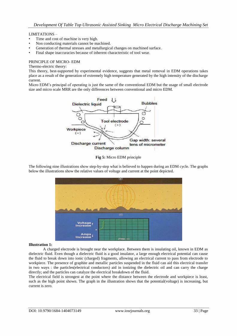
PRINCIPLE OF MICRO- EDM
Thermo-electric theory:
This theory, best-supported by experimental evidence, suggests that metal removal in EDM operations takes
place as a result of the generation of extremely high temperature generated by the high intensity of the discharge
current.
Micro EDM’s principal of operating is just the same of the conventional EDM but the usage of small electrode
size and micro scale MRR are the only differences between conventional and micro EDM.
Fig 5: Micro EDM principle
The following nine illustrations show step-by-step what is believed to happen during an EDM cycle. The graphs
below the illustrations show the relative values of voltage and current at the point depicted.
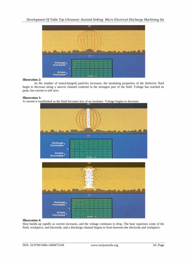
Illustration 1: A charged electrode is brought near the workplace. Between them is insulating oil, known in EDM as
dielectric fluid. Even though a dielectric fluid is a good insulator, a large enough electrical potential can cause
the fluid to break down into ionic (charged) fragments, allowing an electrical current to pass from electrode to
workpiece. The presence of graphite and metallic particles suspended in the fluid can aid this electrical transfer
in two ways : the particles(electrical conductors) aid in ionizing the dielectric oil and can carry the charge
directly; and the particles can catalyze the electrical breakdown of the fluid.
The electrical field is strongest at the point where the distance between the electrode and workpiece is least,
such as the high point shown. The graph in the illustration shows that the potential(voltage) is increasing, but
current is zero.
Development Of Table Top Ultrasonic Assisted Sinking Micro Electrical Discharge Machining Set
DOI: 10.9790/1684-1404073149 www.iosrjournals.org 34 | Page
Illustration 2:
As the number of ionic(charged) particles increases, the insulating properties of the dielectric fluid
begin to decrease along a narrow channel centered in the strongest part of the field. Voltage has reached its
peak, but current is still zero.
Illustration 3: A current is established as the fluid becomes less of an insulator. Voltage begins to decrease.
Illustration 4: Heat builds up rapidly as current increases, and the voltage continues to drop. The heat vaporizes some of the
fluid, workpiece, and electrode, and a discharge channel begins to form between the electrode and workpiece.

Development Of Table Top Ultrasonic Assisted Sinking Micro Electrical Discharge Machining Set
DOI: 10.9790/1684-1404073149 www.iosrjournals.org 35 | Page
Illustration 5:
A vapour bubble tries to expand outward, but its expansion is limited by a rush of ions towards the
discharge channel. These ions are attracted by the extremely intense electro-magnetic field that has built up.
Current continues to rise, voltage drops.
Illustration 6:
Near the end of the on-time, current and voltage have stabilized, heat and pressure within the vapour
bubble have reached their maximum, and some metal is being removed. The layer of metal directly under the
discharge column is in molten state, but is held in place by the pressure of the vapour bubble. The discharge
channel consists now of a superheated plasma made up of vaporized metal, dielectric oil, and carbon with an
intense current passing through it.
Illustration 7: At the beginning of the off-time, current and voltage drop to zero. The temperature decreases rapidly, collapsing
the vapor bubble and causing the molten metal to be expelled from the workpiece.

Development Of Table Top Ultrasonic Assisted Sinking Micro Electrical Discharge Machining Set
DOI: 10.9790/1684-1404073149 www.iosrjournals.org 36 | Page
Illustration 8: Fresh dielectric fluid rushes in, flushing the debris away and quenching the surface of the workpiece.
Unexpelled molten metal solidifies to form what is known as the recast layer.
Illustration 9: The expelled metal solidifies into tiny spheres dispersed in the dielectric oil along with bits of carbon
from the electrode. The remaining vapor rises to the surface. Without a sufficient off-time, debris would collect
making the spark unstable. This situation could create a DC arc which can damage the electrode and the
workpiece. This on/off sequence represents one EDM cycle that can repeat up to 250,000 times per second.
There can be only one cycle occuring at any given time. Once this cycle is understood we can start to control
the duration and intensity of the on/off pulses to make EDM work for us.
Development Of Table Top Ultrasonic Assisted Sinking Micro Electrical Discharge Machining Set
DOI: 10.9790/1684-1404073149 www.iosrjournals.org 37 | Page
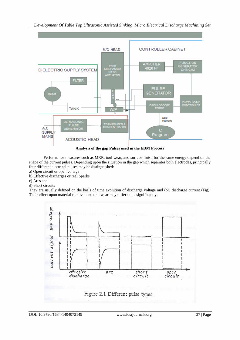
Analysis of the gap Pulses used in the EDM Process
Performance measures such as MRR, tool wear, and surface finish for the same energy depend on the
shape of the current pulses. Depending upon the situation in the gap which separates both electrodes, principally
four different electrical pulses may be distinguished:
a) Open circuit or open voltage
b) Effective discharges or real Sparks
c) Arcs and
d) Short circuits
They are usually defined on the basis of time evolution of discharge voltage and (or) discharge current (Fig).
Their effect upon material removal and tool wear may differ quite significantly.

Development Of Table Top Ultrasonic Assisted Sinking Micro Electrical Discharge Machining Set
DOI: 10.9790/1684-1404073149 www.iosrjournals.org 38 | Page
Open voltages, occurring when the distance between both electrodes is too large, obviously do not
contribute to any material removal or electrode wear.
When contact between tool and workpiece takes place, a short circuit occurs which also does not contribute to
material removal.The range of the electrode distances in between these two extreme cases can be considered to
be a practical working gap yielding actual discharges, i.e., sparks and arcs. Both pulse types do show a
characteristic voltage drop across the gap during a pulse.
The difference between sparks and arcs is quite difficult to establish. It is believed that arcs occur in
the same spot, or on the electrode surface and may therefore severely damage tool and workpiece.
It is assumed that arcs occur when the plasma channel of the previous pulse is not fully deionized; the current
during the following pulse will flow by preference along the same current path. Therefore, in such a case, no
time is required to form a new gaseous current path. The formation of the gaseous channel is normally
considered to be necessary to initiate a new spark breakdown. This peculiarity of EDM arcs is often proposed as
a discrimination characteristic with respect to effective discharges or real sparks.It is believed that only
"sparks" really contribute to material removal in a desired mode. Until now it remains an open question
how much arcs contribute in terms of material removal and tool wear.
DESIGN PRINCIPLES:
Tool or electrode -The mostly used tool material is tungsten carbide .The most powerful technique for
manufacturing micro-tool is WEDG (Wire Electro-Discharge Grinding).Any rod electrode diameter can be
obtained by off-centering, complicated shapes such as asymmetrical, stepped and multi-rods can be formed.
Tungsten carbide (WC) electrodes with a standard diameter of 400 μm and 100 μm are used as a tool electrode.
Stiffness and rigidity of tungsten carbide is very high when comparing to tool steel. This is because tungsten
carbide electrode size can be reduced to very small size and prevents bending or swinging during machining.
Wear resistance of tungsten carbide is also better than that of tool steel. This provides advantages for micro-
hole drilling since less deterioration occur in the shape of target holes.
WEDG is used to prepare smaller size tool down to Ø10 μm by using electrical discharge machining principle
with reverse polarity. Smaller size tool is prepared from larger tools. This process can be divided into two steps.
At first step, the diameter of larger tool is reduced to nearly the desired smaller diameter by rough machining.
At second step, the roughly machined tool diameter is reduced to the desired diameter by using finish
machining parameters.
Fig 5: WEDG for obtaining micro-tool
Straight polarity machining Reverse polarity machining
Fig 6: Principle of obtaining micro-rods
Polarity- The workpiece is usually set as the anode (+) and the wire electrode as the cathode(-) (straight
polarity machining). This is because the discharge energy distributed to the anode is normally greater than that
to the cathode.
Dielectric fluid-It is a nonconductive liquid that fills between the workpiece and electrode and remain
nonconductive until needed space and voltage reaches. At that point dielectric fluid ionizes, becoming an
electrical conductor and cause the current or spark to flow to the workpiece.Different dielectric fluids like
Kerosene, de-ionized water can be used. De ionized water generally has the advantage of faster metal removal
rates .
Development Of Table Top Ultrasonic Assisted Sinking Micro Electrical Discharge Machining Set
DOI: 10.9790/1684-1404073149 www.iosrjournals.org 39 | Page
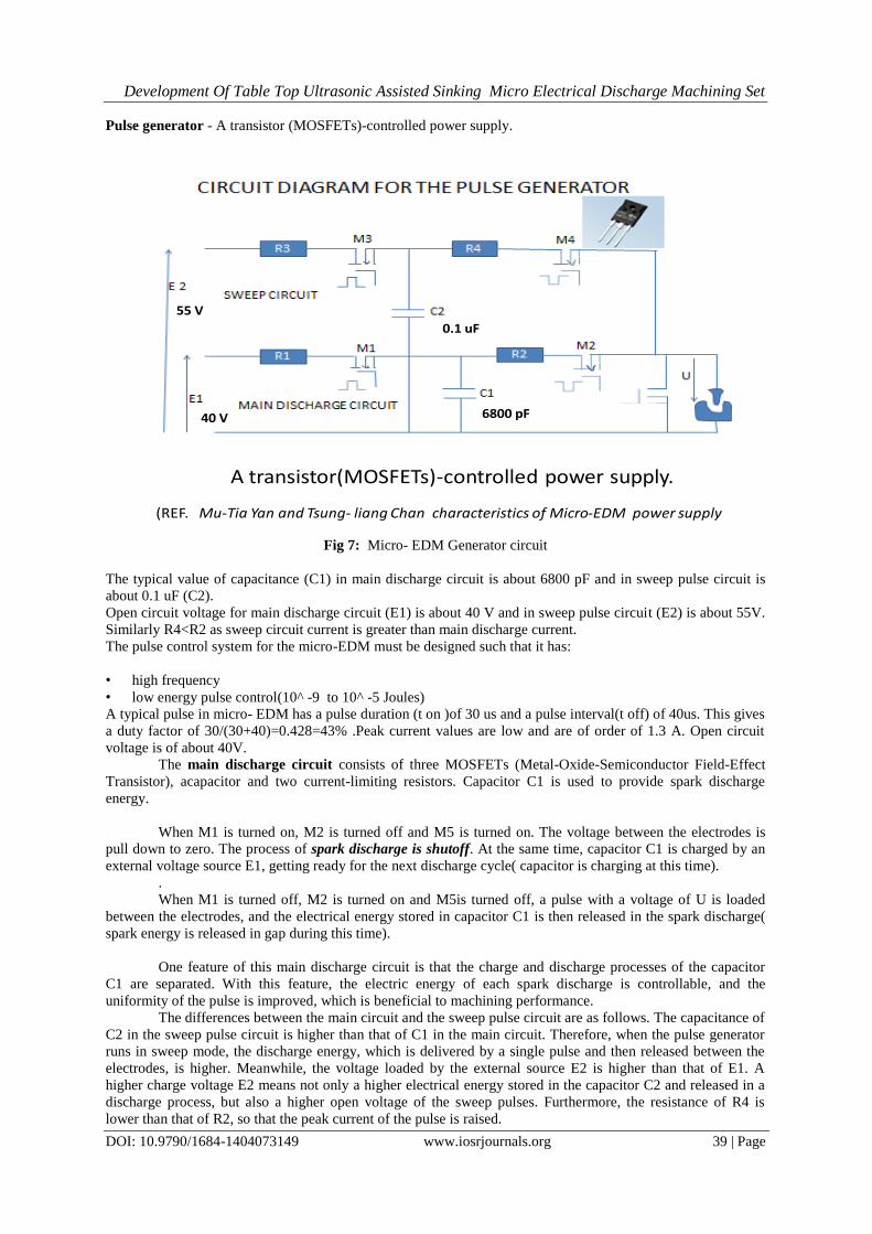
Pulse generator - A transistor (MOSFETs)-controlled power supply.
40 V
55 V
6800 pF
0.1 uF
A transistor(MOSFETs)-controlled power supply.
(REF. Mu-Tia Yan and Tsung- liang Chan characteristics of Micro-EDM power supply
Fig 7: Micro- EDM Generator circuit
The typical value of capacitance (C1) in main discharge circuit is about 6800 pF and in sweep pulse circuit is
about 0.1 uF (C2).
Open circuit voltage for main discharge circuit (E1) is about 40 V and in sweep pulse circuit (E2) is about 55V.
Similarly R4<R2 as sweep circuit current is greater than main discharge current.
The pulse control system for the micro-EDM must be designed such that it has:
• high frequency
• low energy pulse control(10^ -9 to 10^ -5 Joules)
A typical pulse in micro- EDM has a pulse duration (t on )of 30 us and a pulse interval(t off) of 40us. This gives
a duty factor of 30/(30+40)=0.428=43% .Peak current values are low and are of order of 1.3 A. Open circuit
voltage is of about 40V.
The main discharge circuit consists of three MOSFETs (Metal-Oxide-Semiconductor Field-Effect
Transistor), acapacitor and two current-limiting resistors. Capacitor C1 is used to provide spark discharge
energy.
When M1 is turned on, M2 is turned off and M5 is turned on. The voltage between the electrodes is
pull down to zero. The process of spark discharge is shutoff. At the same time, capacitor C1 is charged by an
external voltage source E1, getting ready for the next discharge cycle( capacitor is charging at this time).
.
When M1 is turned off, M2 is turned on and M5is turned off, a pulse with a voltage of U is loaded
between the electrodes, and the electrical energy stored in capacitor C1 is then released in the spark discharge(
spark energy is released in gap during this time).
One feature of this main discharge circuit is that the charge and discharge processes of the capacitor
C1 are separated. With this feature, the electric energy of each spark discharge is controllable, and the
uniformity of the pulse is improved, which is beneficial to machining performance.
The differences between the main circuit and the sweep pulse circuit are as follows. The capacitance of
C2 in the sweep pulse circuit is higher than that of C1 in the main circuit. Therefore, when the pulse generator
runs in sweep mode, the discharge energy, which is delivered by a single pulse and then released between the
electrodes, is higher. Meanwhile, the voltage loaded by the external source E2 is higher than that of E1. A
higher charge voltage E2 means not only a higher electrical energy stored in the capacitor C2 and released in a
discharge process, but also a higher open voltage of the sweep pulses. Furthermore, the resistance of R4 is
lower than that of R2, so that the peak current of the pulse is raised.
Development Of Table Top Ultrasonic Assisted Sinking Micro Electrical Discharge Machining Set
DOI: 10.9790/1684-1404073149 www.iosrjournals.org 40 | Page
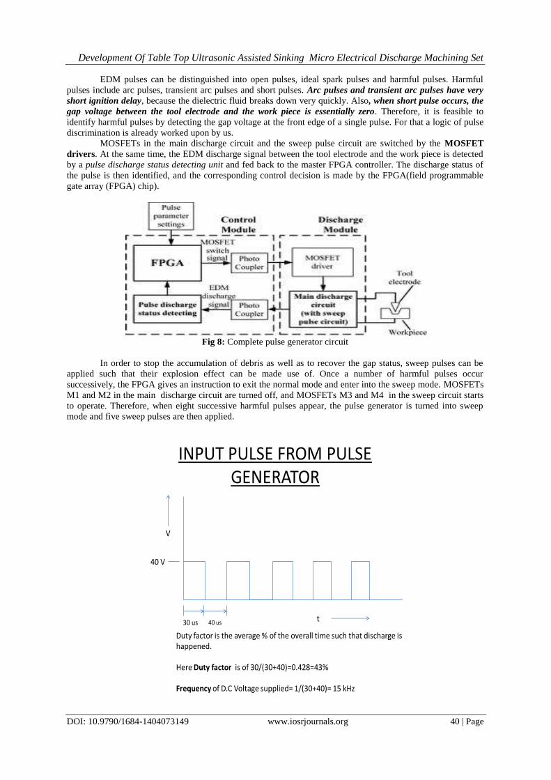
EDM pulses can be distinguished into open pulses, ideal spark pulses and harmful pulses. Harmful
pulses include arc pulses, transient arc pulses and short pulses. Arc pulses and transient arc pulses have very
short ignition delay, because the dielectric fluid breaks down very quickly. Also, when short pulse occurs, the
gap voltage between the tool electrode and the work piece is essentially zero. Therefore, it is feasible to
identify harmful pulses by detecting the gap voltage at the front edge of a single pulse. For that a logic of pulse
discrimination is already worked upon by us.
MOSFETs in the main discharge circuit and the sweep pulse circuit are switched by the MOSFET
drivers. At the same time, the EDM discharge signal between the tool electrode and the work piece is detected
by a pulse discharge status detecting unit and fed back to the master FPGA controller. The discharge status of
the pulse is then identified, and the corresponding control decision is made by the FPGA(field programmable
gate array (FPGA) chip).
Fig 8: Complete pulse generator circuit
In order to stop the accumulation of debris as well as to recover the gap status, sweep pulses can be
applied such that their explosion effect can be made use of. Once a number of harmful pulses occur
successively, the FPGA gives an instruction to exit the normal mode and enter into the sweep mode. MOSFETs
M1 and M2 in the main discharge circuit are turned off, and MOSFETs M3 and M4 in the sweep circuit starts
to operate. Therefore, when eight successive harmful pulses appear, the pulse generator is turned into sweep
mode and five sweep pulses are then applied.
INPUT PULSE FROM PULSE GENERATOR
V
30 us 40 us
Duty factor is the average % of the overall time such that discharge is happened.
Here Duty factor is of 30/(30+40)=0.428=43%
Frequency of D.C Voltage supplied= 1/(30+40)= 15 kHz
40 V
t
Development Of Table Top Ultrasonic Assisted Sinking Micro Electrical Discharge Machining Set
DOI: 10.9790/1684-1404073149 www.iosrjournals.org 41 | Page
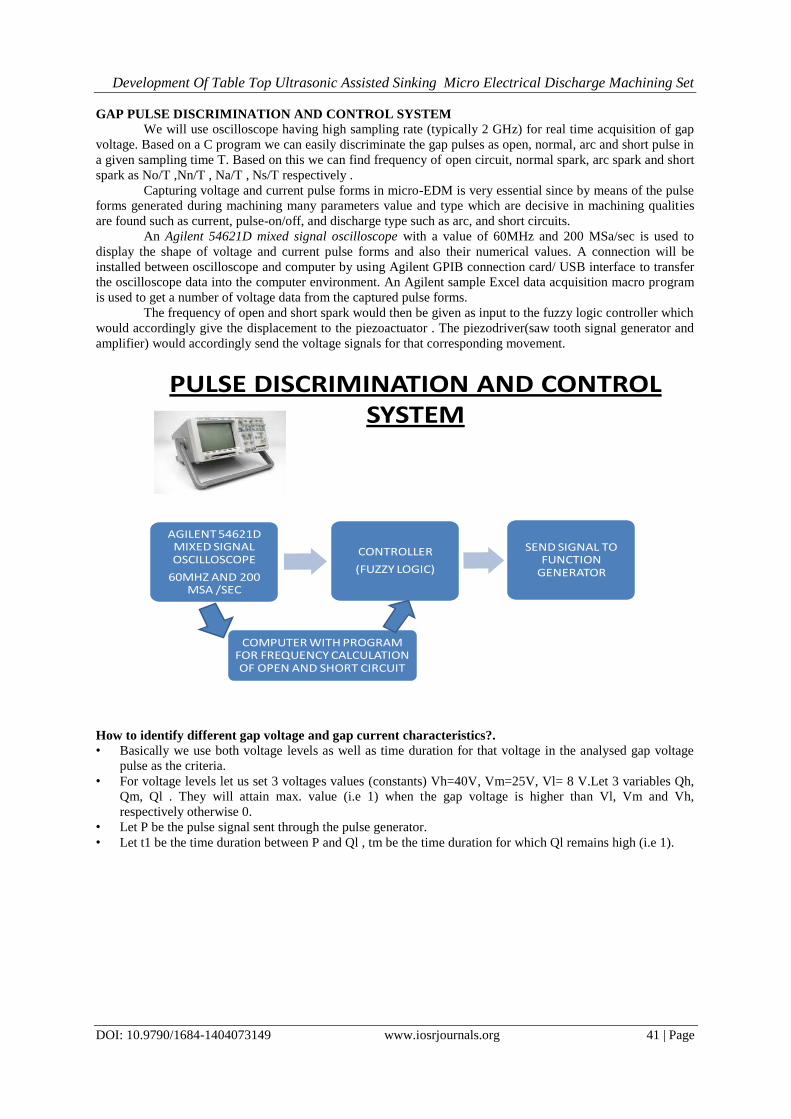
GAP PULSE DISCRIMINATION AND CONTROL SYSTEM
We will use oscilloscope having high sampling rate (typically 2 GHz) for real time acquisition of gap
voltage. Based on a C program we can easily discriminate the gap pulses as open, normal, arc and short pulse in
a given sampling time T. Based on this we can find frequency of open circuit, normal spark, arc spark and short
spark as No/T ,Nn/T , Na/T , Ns/T respectively .
Capturing voltage and current pulse forms in micro-EDM is very essential since by means of the pulse
forms generated during machining many parameters value and type which are decisive in machining qualities
are found such as current, pulse-on/off, and discharge type such as arc, and short circuits.
An Agilent 54621D mixed signal oscilloscope with a value of 60MHz and 200 MSa/sec is used to
display the shape of voltage and current pulse forms and also their numerical values. A connection will be
installed between oscilloscope and computer by using Agilent GPIB connection card/ USB interface to transfer
the oscilloscope data into the computer environment. An Agilent sample Excel data acquisition macro program
is used to get a number of voltage data from the captured pulse forms.
The frequency of open and short spark would then be given as input to the fuzzy logic controller which
would accordingly give the displacement to the piezoactuator . The piezodriver(saw tooth signal generator and
amplifier) would accordingly send the voltage signals for that corresponding movement.
PULSE DISCRIMINATION AND CONTROL SYSTEM
AGILENT 54621D MIXED SIGNAL OSCILLOSCOPE
60MHZ AND 200 MSA /SEC
CONTROLLER
(FUZZY LOGIC)
SEND SIGNAL TO FUNCTION
GENERATOR
COMPUTER WITH PROGRAM FOR FREQUENCY CALCULATION OF OPEN AND SHORT CIRCUIT
How to identify different gap voltage and gap current characteristics?.
• Basically we use both voltage levels as well as time duration for that voltage in the analysed gap voltage
pulse as the criteria.
• For voltage levels let us set 3 voltages values (constants) Vh=40V, Vm=25V, Vl= 8 V.Let 3 variables Qh,
Qm, Ql . They will attain max. value (i.e 1) when the gap voltage is higher than Vl, Vm and Vh,
respectively otherwise 0.
• Let P be the pulse signal sent through the pulse generator.
• Let t1 be the time duration between P and Ql , tm be the time duration for which Ql remains high (i.e 1).

Development Of Table Top Ultrasonic Assisted Sinking Micro Electrical Discharge Machining Set
DOI: 10.9790/1684-1404073149 www.iosrjournals.org 42 | Page
40 V
25 V
8V
OPEN NORMAL SPARK ARC
SHORT
Micro EDM Generator pulsesP
Ql
Qm
Qh
t
tm
t1
LOGIC APPLIED
• For open circuit –
t1s=t1
tms=tm
P remains high and Ql, Q m, Q h remain high.
• For normal spark –
t1 =t1s
tm<tms
P remains high and Ql, Q m, Q h remain high.
• For arc –
t1=t1s
P remains high Qm and Qh remains low.
• For short spark –
t1>t1s
P remains high. Qm and Qh remains low.
PROGRAM CODE FOR GAP PULSE IDENTIFICATION
Set t1s=t1 corresponding to open circuit .Similarly set tms=tm corresponding to open circuit.
Now for the time duration T :
If( (t1>t1s)&&( P==1)&&(Qm==0)&&(Qh==0))
Ns++; // no. of short sparks
Else If( (t1== t1s)&&( P==1)&&(Qm==0)&&(Qh==0))
Na++; // no. of arc sparks
Else If( (t1==t1s)&& (tm<tms) &&( P==1)&&(Ql==1)&&(Qm==1)&&(Qh==1))
Nn++; // no. of normal sparks
Else If( (t1==t1s)&& (tm==tms)&&( P==1)&&(Ql==1)&&(Qm==1)&&(Qh==1))
No++; //open circuit pulses
Now frequency for open, normal, arc and short can be calculated using as No/T ,Nn/T , Na/T , Ns/T in the
sampling period and sent to controller.
Controller design
There is a self-regulating feature in EDM but the process still needs controller for micro-hole operations.
Micro-EDM controller gives signals for the servo feed mechanism based on the sensed gap conditions. Here we
are going to use fuzzy logic controller instead of PID as the process of micro EDM is highly stochastic and the
difficulty of using mathematical model to precisely describe EDM process render PID controllers less
competitive in preventing undesired arc and short circuit pulse.

Development Of Table Top Ultrasonic Assisted Sinking Micro Electrical Discharge Machining Set
DOI: 10.9790/1684-1404073149 www.iosrjournals.org 43 | Page
Fuzzy logic can make use of the operator experience for controller design. The membership function for the
input i.e the frequency of the open and short circuit as well as the output membership function of piezoelectric
displacement can be decided by the operator .Based on experimentation, he can decide upon the rule base for
displacement corresponding to input parameters.
USING FUZZY-LOGIC FOR GAP-WIDTH CONTROL
Fuzzy-technologies has been applied with big success for the control of processes whose transfer
functions are unknown or hard to describe. Also in the field of EDM an increasingnumber of fuzzy process-
control systems can be observed. This is supported by the following features of fuzzy logic:
• Fuzzy-Controllers are comprehensible, because their concept is close to human thinking.
• User knowledge can be integrated in the control system
• For controller design it is sufficient to formulate the coherences of the problem domain which even can have
contradictory influences.
The gap-width controller based on the rel. frequency of short-circuits and open circuits can be implemented
using fuzzy technologies. The strategy of this controller can be characterized as follows:
1. If little short circuits and open-circuits don’t move electrode
2. If more short circuits move electrode backward
3. If much open-circuits move electrode forward
So far the fuzzy terms „little“, „more“ and „much“ were implemented using thresholds for tolerated open-
circuits and short-circuits. With the possibilities of fuzzy-logic the control behaviour can much finer be graded.
Figure shows the principle design of a fuzzy-controller. The measured input data must be “fuzzyfied“ before
further processing. This is done inside the fuzzyfication component using membership functions. In the next
step statement about the output are made inside the inference module using if ..then clauses. At the end the
ouput is converted into a format thatcan be sent to an actuator.
Gaussian Membership function for frequency of open circuit (input)
Gaussian Membership function for frequency of short circuit (input)

Development Of Table Top Ultrasonic Assisted Sinking Micro Electrical Discharge Machining Set
DOI: 10.9790/1684-1404073149 www.iosrjournals.org 44 | Page
Gaussian Membership function for tool electrode movement(output)
Surface map inside controller

Development Of Table Top Ultrasonic Assisted Sinking Micro Electrical Discharge Machining Set
DOI: 10.9790/1684-1404073149 www.iosrjournals.org 45 | Page
We can see the surface maps generated in controller for controlling feed in matlab using-
Fis = readfis (‘fuzzy-controller');
surfview (fis);
by using matlab command
d=evalfis ([90 20],fis);
Where 90% is open circuit frequency and 20% is short circuit frequency.
we can get the distance(d) to be moved in either forward or reverse direction for controlling the gap width for
spark generation.
Development Of Table Top Ultrasonic Assisted Sinking Micro Electrical Discharge Machining Set
DOI: 10.9790/1684-1404073149 www.iosrjournals.org 46 | Page
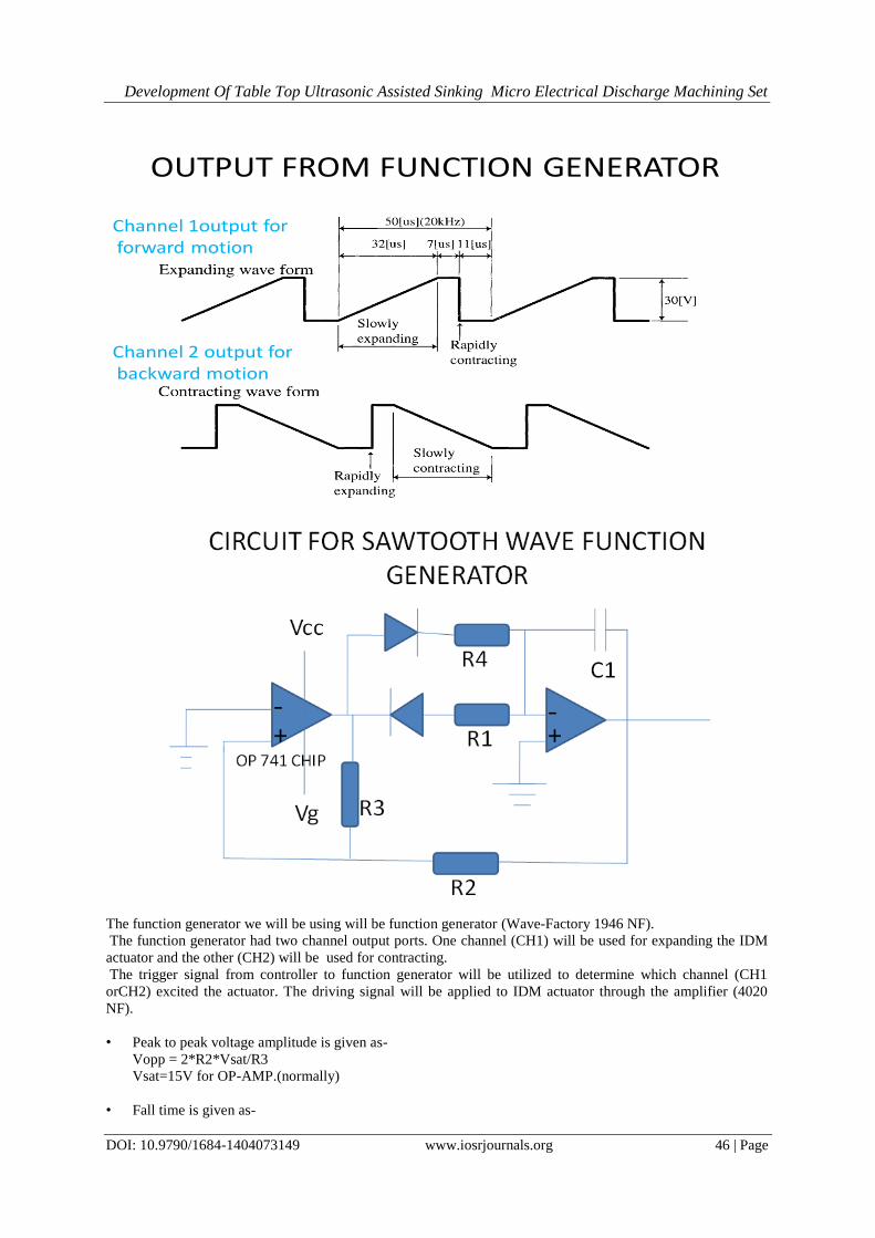
OUTPUT FROM FUNCTION GENERATOR
Channel 1output forforward motion
Channel 2 output forbackward motion
The function generator we will be using will be function generator (Wave-Factory 1946 NF).
The function generator had two channel output ports. One channel (CH1) will be used for expanding the IDM
actuator and the other (CH2) will be used for contracting.
The trigger signal from controller to function generator will be utilized to determine which channel (CH1
orCH2) excited the actuator. The driving signal will be applied to IDM actuator through the amplifier (4020
NF).
• Peak to peak voltage amplitude is given as-
Vopp = 2*R2*Vsat/R3
Vsat=15V for OP-AMP.(normally)
• Fall time is given as-
Development Of Table Top Ultrasonic Assisted Sinking Micro Electrical Discharge Machining Set
DOI: 10.9790/1684-1404073149 www.iosrjournals.org 47 | Page
Tfall=2*R4*C1*R2/R3
• Rise time is given as-
Trise=2*R1*C1*R2/R3
As the driving frequency of the sawtooth wave is of 20 kHz .
So for forward stroke when Vpp=30 V ,trise=32 us , tfall=18 us .(CH1 Circuit parameters)
• R2=20 kΏ =R3
• R1=32 kΏ
• R4=18 kΏ
• C1=500 pF
So for Reverse stroke when Vpp=30 V ,trise=18 us , tfall=32 us.(CH2 Circuit parameters)
• R2=20 kΏ =R3
• R1=18 kΏ
• R4=32 kΏ
• C1=500 Pf
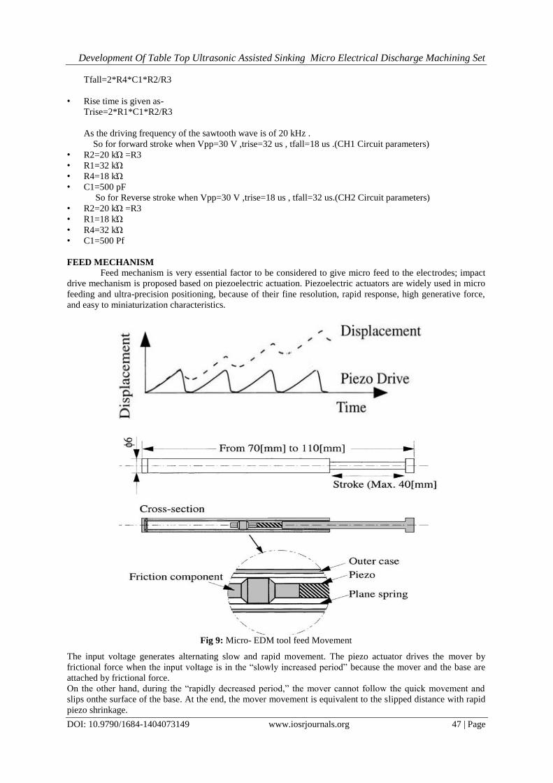
FEED MECHANISM Feed mechanism is very essential factor to be considered to give micro feed to the electrodes; impact
drive mechanism is proposed based on piezoelectric actuation. Piezoelectric actuators are widely used in micro
feeding and ultra-precision positioning, because of their fine resolution, rapid response, high generative force,
and easy to miniaturization characteristics.
Fig 9: Micro- EDM tool feed Movement
The input voltage generates alternating slow and rapid movement. The piezo actuator drives the mover by
frictional force when the input voltage is in the “slowly increased period” because the mover and the base are
attached by frictional force.
On the other hand, during the “rapidly decreased period,” the mover cannot follow the quick movement and
slips onthe surface of the base. At the end, the mover movement is equivalent to the slipped distance with rapid
piezo shrinkage.
Development Of Table Top Ultrasonic Assisted Sinking Micro Electrical Discharge Machining Set
DOI: 10.9790/1684-1404073149 www.iosrjournals.org 48 | Page
By repeating these operations, the mover could be driven with a long stroke.
To reverse the moving direction, the shapeof the electrical source is modified to what is composed of “rapidly
increased period” anda “slowly decreased period.
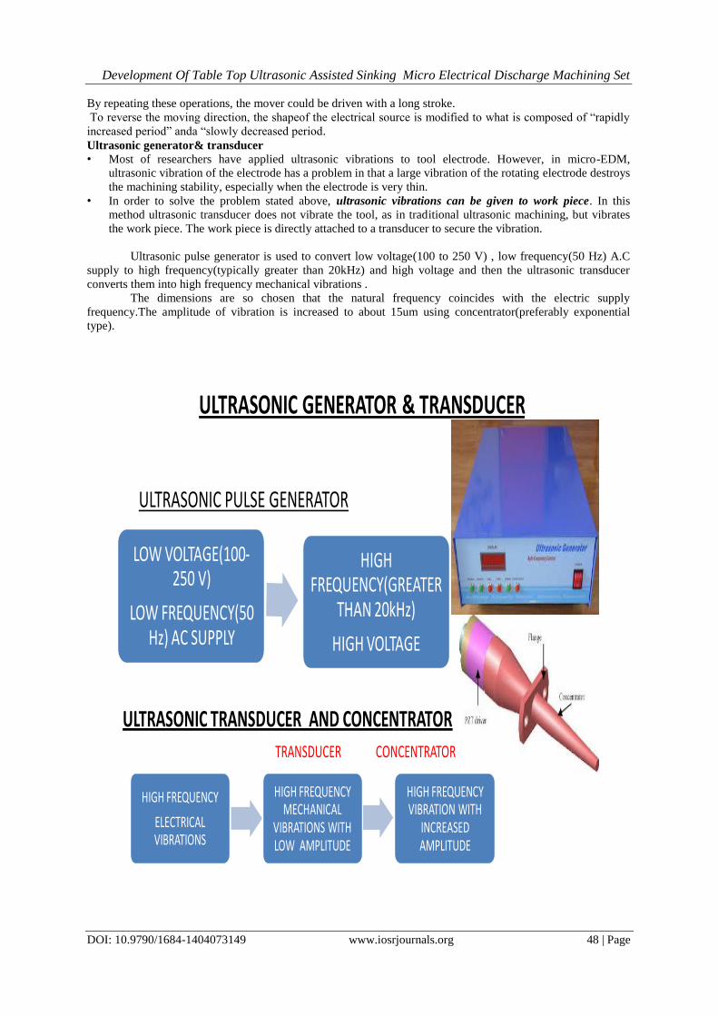
Ultrasonic generator& transducer
• Most of researchers have applied ultrasonic vibrations to tool electrode. However, in micro-EDM,
ultrasonic vibration of the electrode has a problem in that a large vibration of the rotating electrode destroys
the machining stability, especially when the electrode is very thin.
• In order to solve the problem stated above, ultrasonic vibrations can be given to work piece. In this
method ultrasonic transducer does not vibrate the tool, as in traditional ultrasonic machining, but vibrates
the work piece. The work piece is directly attached to a transducer to secure the vibration.
Ultrasonic pulse generator is used to convert low voltage(100 to 250 V) , low frequency(50 Hz) A.C
supply to high frequency(typically greater than 20kHz) and high voltage and then the ultrasonic transducer
converts them into high frequency mechanical vibrations .
The dimensions are so chosen that the natural frequency coincides with the electric supply
frequency.The amplitude of vibration is increased to about 15um using concentrator(preferably exponential
type).
LOW VOLTAGE(100-250 V)
LOW FREQUENCY(50 Hz) AC SUPPLY
HIGH FREQUENCY(GREATER
THAN 20kHz)
HIGH VOLTAGE
ULTRASONIC GENERATOR & TRANSDUCER
ULTRASONIC PULSE GENERATOR
ULTRASONIC TRANSDUCER AND CONCENTRATOR
HIGH FREQUENCY
ELECTRICAL VIBRATIONS
HIGH FREQUENCY MECHANICAL
VIBRATIONS WITH LOW AMPLITUDE
HIGH FREQUENCY VIBRATION WITH
INCREASED AMPLITUDE
TRANSDUCER CONCENTRATOR

Development Of Table Top Ultrasonic Assisted Sinking Micro Electrical Discharge Machining Set
DOI: 10.9790/1684-1404073149 www.iosrjournals.org 49 | Page
SIMULINK MODEL FOR THE EDM SYSTEM
SIMULATION RESULT –
ACKNOWLEDGEMENT
At the outset, we take this opportunity to acknowledge our regards to all those people who extended their
cooperation and played an important role in completion of this project. We express our sincer thanks to
Dr. Vinod Yadav. “Development Of Table Top Ultrasonic Assisted Sinking Micro Electrical
Discharge Machining Set Up.” IOSR Journal of Mechanical and Civil Engineering (IOSR-
JMCE) , vol. 14, no. 4, 2017, pp. 31–39.