Micro Control X Model : PXF5/9 - Instrumart
24
- 1 - Model : PXF5/9 Micro Control X Instruction Manual INP-TN2PXF5/9a-E Grobal Sales Section Instrumentation & Sensors Planning Dept. 1, Fuji-machi, Hino-city, Tokyo 191-8502, Japan http://www.fujielectric.com Phone: +81-42-514-8930 Fax: +81-42-583-8275 http://www.fujielectric.com/products/instruments/ Thank you for purchasing the Fuji module type temperature controller. Once you have confirmed that this is the product you ordered, please use it in accordance with the following instructions. For detailed information on operating this equipment, please refer to the separate user's manual. In addition, please keep this instruction manual within easy reach of the actual person using this equipment. Please Read First (Safety Warnings) Please read this section thoroughly before using and observe the mentioned safety warnings fully. Safety warnings are categorized as “Warning” or “Caution”. Failure to follow the instructions may result in a safety hazard. Warning mishandling may lead to minor or serious personal injury, fire, and/or property damage. Caution Mishandling may cause injury to the user or property damage. If the equipment is used in a manner not specified by the manufacturer, the protection provided by the equipment may be impaired. 1. Warning 1-1. Limitations in Use This product is a temperature controller which was developed, designed and manufactured on the premise that it would be used for general machinery. In particular, if this product is to be used for applications that require the utmost safety as described below, please take into consideration of the safety of the entire system and the machine by adopting such means as a fail-safe design, a redundancy design as well as the conducting of periodical inspections. • Safety devices for the purpose of protecting the human body • Direct control of transportation equipment • Airplanes • Space equipment • Atomic equipment, etc. Please do not use this product for applications which directly involve human lives. CAUTION The contents of this manual are subject to change without notice. This manual is complied with possible care for the purpose of accuracy, however, Fuji Electric shall not be held liable for any damages, including indirect damage, caused by typographical errors, absence of information or use of information in this manual. 1-2. Installation and Wiring ► This equipment is intended to be used under the following conditions. Ambient temperature -10 °C to 50 °C Ambient humidity 90% RH or below (with no condensation) Overvoltage category II by IEC 61010-1 Pollution degree 2 Recommended fuse 250VAC, 0.1A T(Time-Lag) for 100 to 240V AC Power supply, 400V DC/400V AC, 1A T(Time-Lag) for 24V DC/24V AC Power supply Usage environment Indoor use ► If accessible Safety Extra Low Voltage (SELV) circuits are to be connected to Signal input terminal, SSR Drive output terminal, Current output terminal or Communication (RS485) terminal, ensure to provide a basic insulation between the SELV circuits and these terminals (For example, use transformer which has a basic insulation or higher degree of insulation). The basic insulation requires a clearance at least 1.5 mm and a creepage of at least 3.0 mm. If such insulation is not provided, the UL61010 and EN61010 safety compliance may become invalid. ► For 24V DC/AC power supply model, if the equipment is connected to the Safety Extra Low Voltage (SELV) circuit, a basic insulation must be provided between the SELV circuit and the power input terminals. Otherwise, the power input terminals must be connect to Extra Low Voltage (ELV) circuit so as to prevent the electric shock. ► For CT input, use Current Transfer which has specification as shown below in order to prevent the electric shock and spread of fire. 1) Over Voltage Category II 2) Pollution Degree 2 3) Required level of Insulating BASIC INSULATION, SUPPLYMENTARY INSULATION, or REINFORCED INSULATION 4) Maximum Voltage line to neutral 300Vac rms or 300Vdc About safety standard Please observe the following instructions to meet the requirements of safety standard. Failure to observe these instructions violates safety standards. (This product is not a safety equipment.) ……………………………………………………………………………………………………………………………… ● Install a recommended fuse, which is specified in the instruction manual, between the external main power (mains circuit) and this equipment. ● If accessible Safety Extra Low Voltage (SELV) circuits are to be connected to Signal input terminal, SSR Drive output terminal, Current output terminal or Communication (RS485) terminal, ensure to provide a basic insulation between the SELV circuits and these terminals (For example, use transformer which has a basic insulation or higher degree of insulation). The basic insulation requires a clearance at least 1.5 mm and a creepage of at least 3.0 mm. If such insulation is not provided, the UL61010 and EN61010 safety compliance may become invalid. ● Whole this equipment must be mounted in an enclosure in order to prevent the electric shock and spread of fire. ● Be sure to install an appropriate external protective circuit to prevent excessive temperature rise etc. ● When performing wiring work, be sure to turn the power off and to wear protection gloves or safety glasses, to prevent an electric shock. ● Set proper parameter input signals which correspond to each input to be connected. Be careful not to confuse voltage input with current input, or vice versa. ● Do not use this equipment for the measurement of circuits which falls under measurement categories II, III, or IV. ● Do not use this equipment for measurement of signals to which a voltage over 30 VRMS or over 60 V DC is applied. ● If there is a risk that anyone may come into contact with the terminal while the instrument is being energized, attach the terminal cover (optional) to prevent an electric shock. Before removing a terminal cover, turn off all the power. ……………………………………………………………………………………………………………………………… ► Note that the insulation class for this equipment is as follows. Before installing, please confirm that the insulation class for equipment meets usage requirements. Internal circuit Process value input Remote SV input CT input Valve position feedback (PFB) input Control output 1 (SSR drive, current, voltage) Valve position feedback (PFB) input Control output 1 (SSR drive, current, voltage) Control output 2 (SSR drive, current, voltage) or Transfer output Control output 2 (SSR drive, current, voltage) or Transfer output Digital input 1 to 5 Communication (RS-485) Power supply (100 to 240V AC) Control output 1 (relay contact) or Motorized valve OPEN output Control output 2 (relay contact) or Motorized valve CLOSE output Alarm output 1 (relay contact) Alarm output 1 to 3 (relay contact) Alarm output 2 (relay contact) Control output 1 (relay contact) or Motorized valve OPEN output Control output 2 (relay contact) or Motorized valve CLOSE output Alarm output 1 (relay contact) Alarm output 1 to 3 (relay contact) Alarm output 2 (relay contact) Basic insulation (1500 V AC) Functional insulation (500 V AC) No insulation (1) (2) (1) (2) Internal circuit Process value input Remote SV input CT input Digital input 1 to 5 Communication (RS-485) Power supply (24V DC/24V AC) Alarm output 4 and 5 (relay contact) Alarm output 4 and 5 (relay contact) (1): When the 9th code is "J" AL 1 and 2: independent common (2): When the 9th code is other than "J" AL 1 to 3: shared common ● A power switch or a circuit breaker should be installed within the power supply facility. ● A power switch or a circuit breaker should be properly installed within easy reach of an operator. ● A power switch or a circuit breaker should be identified as the one for this product. ● Electrical wiring must be made by the qualified personnel only and in accordance with your local and national standards. ● For power supply wiring, use wire equal to 600V vinyl insulated wire or above. ● To prevent damage and failure of the equipment, provide the rated power voltage. ● To prevent shock and equipment failure, do not turn the power ON until all wiring is complete. ● Before turning on power, confirm that clearance space has been secured to prevent shock or fire. ● Do not touch the terminal while the machine is on. Doing so risks shock or equipment errors. ● Never disassemble, convert, modify or repair this equipment. Doing so risks abnormal operation, shock or fire. ● If any failure occurs, please contact the manufacturer and return the product. ● Output relay is the part has a limited life. When output relay contact comes to the end of its life, it might remain on-state, or off-state. For safety, use a protective circuit outside. ● The factory default setting of this equipment is as follows. Change the setting as necessary so as the equipment to meet your application. Please note that the improper settings may result in overheat or unexpected damage. For the details of operation, refer to the separate volume, "Operation Manual (INP-TN5A2400-E)". Control output 1: heating control Control output 2 (optional): cooling control Alarm output 1 (optional): no alarm Alarm output 2 (optional): no alarm Alarm output 3 (optional): no alarm Alarm output 4 (optional): no alarm Alarm output 5 (optional): no alarm ● Symbols on the instrument : Read this instruction manual thoroughly before using the product, and usethe product safely. 1-3. Maintenance ● When installing or removing the equipment, turn the power OFF. Otherwise, shock, operational errors or failures may be caused. ● Periodic maintenance is recommended for continuous and safe use of this equipment. ● Some parts installed on this equipment have a limited life and/or may deteriorate with age. ● The warranty period for this unit (including accessories) is three years after the date of manufacture, if the product is used properly. Confirming Specifications and Accessories Before using the product, confirm that it matches the type ordered. (For model code, please refer to pages 22 - 23.) Confirm that all of the following accessories are included. Temperature Controller 1 unit Instruction Manual 1 copy Panel mounting adapter 2 pc Waterproof packing 1 pc Related Information Refer to the following reference materials for details about the items described in this manual. Document Reference No. Data sheet EDS11-179 EDS11-180 Micro Controller (Model: PXF) Operation Manual INP-TN5A2400-E Micro Controller (Model: PXF) Communication Functions Manual (MODBUS) INP-TN5A2227-E The latest manuals can also be downloaded at the following URL: http://www.fujielectric.com/products/instruments/ Option Name Quantity Order No. Terminal cover* 1 pc ZZPPXF1-B100 PC loader communication cable 1 cable ZZP*TQ501923C3 Shunt resistor (250Ω ± 0.1%) 1 pc ZZPPXR1-A190 *For PXF9, two terminal covers are necessary for one unit.
Transcript of Micro Control X Model : PXF5/9 - Instrumart

- 1 -
Model : PXF5/9Micro Control X
Instruction Manual
INP-TN2PXF5/9a-E
Grobal Sales SectionInstrumentation & Sensors Planning Dept.1, Fuji-machi, Hino-city, Tokyo 191-8502, Japanhttp://www.fujielectric.comPhone: +81-42-514-8930 Fax: +81-42-583-8275http://www.fujielectric.com/products/instruments/
Thank you for purchasing the Fuji module type temperature controller.Once you have confirmed that this is the product you ordered, please use it in accordance with the following instructions.For detailed information on operating this equipment, please refer to the separate user's manual.In addition, please keep this instruction manual within easy reach of the actual person using this equipment.
Please Read First (Safety Warnings)Please read this section thoroughly before using and observe the mentioned safety warnings fully. Safety warnings are categorized as “Warning” or “Caution”. Failure to follow the instructions may result in a safety hazard.
Warning mishandling may lead to minor or serious personal injury, fire, and/or property damage.
Caution Mishandling may cause injury to the user or property damage.
If the equipment is used in a manner not specified by the manufacturer, the protection provided by the equipment may be impaired.
1. Warning
1-1. Limitations in UseThis product is a temperature controller which was developed, designed and manufactured on the premise that it would be used for general machinery.In particular, if this product is to be used for applications that require the utmost safety as described below, please take into consideration of the safety of the entire system and the machine by adopting such means as a fail-safe design, a redundancy design as well as the conducting of periodical inspections.
• Safety devices for the purpose of protecting the human body• Direct control of transportation equipment• Airplanes• Space equipment• Atomic equipment, etc.
Please do not use this product for applications which directly involve human lives.
CAUTIONThe contents of this manual are subject to change without notice.This manual is complied with possible care for the purpose of accuracy, however, Fuji Electric shall not be held liable for any damages, including indirect damage, caused by typographical errors,absence of information or use of information in this manual.
1-2. Installation and Wiring This equipment is intended to be used under the following conditions.
Ambient temperature -10 °C to 50 °CAmbient humidity 90% RH or below (with no condensation)Overvoltage category II
by IEC 61010-1Pollution degree 2
Recommended fuse 250VAC, 0.1A T(Time-Lag) for 100 to 240V AC Power supply,400V DC/400V AC, 1A T(Time-Lag) for 24V DC/24V AC Power supply
Usage environment Indoor use
If accessible Safety Extra Low Voltage (SELV) circuits are to be connected to Signal input terminal, SSR Drive output terminal, Current output terminal or Communication (RS485) terminal, ensure to provide a basic insulation between the SELV circuits and these terminals (For example, use transformer which has a basic insulation or higher degree of insulation). The basic insulation requires a clearance at least 1.5 mm and a creepage of at least 3.0 mm. If such insulation is not provided, the UL61010 and EN61010 safety compliance may become invalid.
For 24V DC/AC power supply model, if the equipment is connected to the Safety Extra Low Voltage (SELV) circuit, a basic insulation must be provided between the SELV circuit and the power input terminals. Otherwise, the power input terminals must be connect to Extra Low Voltage (ELV) circuit so as to prevent the electric shock.
For CT input, use Current Transfer which has specification as shown below in order to prevent the electric shock and spread of fire.1) Over Voltage Category II2) Pollution Degree 2
3) Required level of Insulating BASIC INSULATION, SUPPLYMENTARY INSULATION, or REINFORCED INSULATION
4) Maximum Voltage line to neutral 300Vac rms or 300Vdc
About safety standard
Please observe the following instructions to meet the requirements of safety standard.Failure to observe these instructions violates safety standards. (This product is not a safety equipment.)……………………………………………………………………………………………………………………………… Install a recommended fuse, which is specified in the instruction manual, between the external main power
(mains circuit) and this equipment. If accessible Safety Extra Low Voltage (SELV) circuits are to be connected to Signal input terminal, SSR
Drive output terminal, Current output terminal or Communication (RS485) terminal, ensure to provide a basic insulation between the SELV circuits and these terminals (For example, use transformer which has a basic insulation or higher degree of insulation). The basic insulation requires a clearance at least 1.5 mm and a creepage of at least 3.0 mm. If such insulation is not provided, the UL61010 and EN61010 safety compliance may become invalid.
Whole this equipment must be mounted in an enclosure in order to prevent the electric shock and spread of fire.
Be sure to install an appropriate external protective circuit to prevent excessive temperature rise etc. When performing wiring work, be sure to turn the power off and to wear protection gloves or safety glasses,
to prevent an electric shock. Set proper parameter input signals which correspond to each input to be connected. Be careful not to
confuse voltage input with current input, or vice versa. Do not use this equipment for the measurement of circuits which falls under measurement categories II, III,
or IV. Do not use this equipment for measurement of signals to which a voltage over 30 VRMS or over 60 V DC is
applied. If there is a risk that anyone may come into contact with the terminal while the instrument is being
energized, attach the terminal cover (optional) to prevent an electric shock. Before removing a terminal cover, turn off all the power.
………………………………………………………………………………………………………………………………
Note that the insulation class for this equipment is as follows. Before installing, please confirm that the insulation class for equipment meets usage requirements.
Internal circuit
Process value input
Remote SV input
CT input
Valve position feedback (PFB) input
Control output 1 (SSR drive, current, voltage)
Valve position feedback (PFB) input
Control output 1 (SSR drive, current, voltage)
Control output 2 (SSR drive, current,voltage) or Transfer output
Control output 2 (SSR drive, current,voltage) or Transfer output
Digital input 1 to 5
Communication (RS-485)
Power supply (100 to 240V AC)
Control output 1 (relay contact) or
Motorized valve OPEN output
Control output 2 (relay contact) or
Motorized valve CLOSE output
Alarm output 1(relay contact) Alarm output
1 to 3(relay contact)Alarm output 2
(relay contact)
Control output 1 (relay contact) or
Motorized valve OPEN output
Control output 2 (relay contact) or
Motorized valve CLOSE output
Alarm output 1(relay contact) Alarm output
1 to 3(relay contact)Alarm output 2
(relay contact)
Basic insulation (1500 V AC) Functional insulation (500 V AC) No insulation
(1) (2) (1) (2)
Internal circuit
Process value input
Remote SV input
CT input
Digital input 1 to 5
Communication (RS-485)
Power supply (24V DC/24V AC)
Alarm output 4 and 5 (relay contact) Alarm output 4 and 5 (relay contact)
(1): When the 9th code is "J" AL 1 and 2: independent common(2): When the 9th code is other than "J" AL 1 to 3: shared common
A power switch or a circuit breaker should be installed within the power supply facility. A power switch or a circuit breaker should be properly installed within easy reach of an operator. A power switch or a circuit breaker should be identified as the one for this product. Electrical wiring must be made by the qualified personnel only and in accordance with your local
and national standards. For power supply wiring, use wire equal to 600V vinyl insulated wire or above. To prevent damage and failure of the equipment, provide the rated power voltage. To prevent shock and equipment failure, do not turn the power ON until all wiring is complete. Before turning on power, confirm that clearance space has been secured to prevent shock or fire. Do not touch the terminal while the machine is on. Doing so risks shock or equipment errors. Never disassemble, convert, modify or repair this equipment. Doing so risks abnormal operation,
shock or fire. If any failure occurs, please contact the manufacturer and return the product. Output relay is the part has a limited life. When output relay contact comes to the end of its life, it
might remain on-state, or off-state. For safety, use a protective circuit outside. The factory default setting of this equipment is as follows. Change the setting as necessary so
as the equipment to meet your application. Please note that the improper settings may result in overheat or unexpected damage.
For the details of operation, refer to the separate volume, "Operation Manual (INP-TN5A2400-E)". Control output 1: heating control Control output 2 (optional): cooling control Alarm output 1 (optional): no alarm Alarm output 2 (optional): no alarm Alarm output 3 (optional): no alarm Alarm output 4 (optional): no alarm Alarm output 5 (optional): no alarm Symbols on the instrument : Read this instruction manual thoroughly before using the product, and usethe product safely.
1-3. Maintenance When installing or removing the equipment, turn the power OFF. Otherwise, shock, operational
errors or failures may be caused. Periodic maintenance is recommended for continuous and safe use of this equipment. Some parts installed on this equipment have a limited life and/or may deteriorate with age. The warranty period for this unit (including accessories) is three years after the date of manufacture,
if the product is used properly.
Confirming Specifications and Accessories
Before using the product, confirm that it matches the type ordered.(For model code, please refer to pages 22 - 23.) Confirm that all of the following accessories are included.
Temperature Controller 1 unitInstruction Manual 1 copyPanel mounting adapter 2 pcWaterproof packing 1 pc
Related Information
Refer to the following reference materials for details about the items described in this manual.
Document Reference No.
Data sheet EDS11-179EDS11-180
Micro Controller (Model: PXF) Operation Manual INP-TN5A2400-E
Micro Controller (Model: PXF) Communication Functions Manual (MODBUS)
INP-TN5A2227-E
The latest manuals can also be downloaded at the following URL: http://www.fujielectric.com/products/instruments/
OptionName Quantity Order No.Terminal cover* 1 pc ZZPPXF1-B100PC loader communication cable 1 cable ZZP*TQ501923C3
Shunt resistor (250Ω ± 0.1%) 1 pc ZZPPXR1-A190
*For PXF9, two terminal covers are necessary for one unit.

- 2 - - 3 -
2. Caution
2-1. Cautions when InstallingPlease avoid installing in the following locations. Locations in which the ambient temperature falls outside the range of –10 to 50°C when equipment
is in use. (If the power supply is 200V AC, the recommended maximum ambient temperature is 45°C.)
Locations with rapid temperature changes, leading to dew condensation Locations with corrosive gases (especially sulfide gas, ammonia, etc.) or flammable gases. Locations with vibration or shock directly. (Vibration and shock may cause output relay malfunction.) Locations in contact with water, oil, chemicals, steam or hot water. (If the equipment gets wet, there is a risk of electric shock or fire, so have it inspected by Fuji
distributor.) Locations with high concentrations of atmospheric dust, salt or iron particles. Locations with large inductive interference, resulting in static electricity, magnetic fields or noise Locations in direct sunlight. Locations that build up heat from radiant heat sources, etc.
Recommended site conditions A place where the ambient humidity during operaion is between 45 to 85%RH.
About EMC standard
This equipment is a class A , for industrial locations, equipment. Do not use this equipment in domestic establishment, such as residential areas, or it may cause radio interference. If you use this equipment in domestic locations, take adequate measures on the outside of the equipment to reduce radio interference.
Under the requirement of EMC standard, the maximum length of external cable including a sensor to be connected to this equipment is 30 m. Do not connect the sensor longer than 30 m.
2-2. Cautions when Attaching to the Panels Please attach the PXF5/PXF9 with the included fixtures (2 pieces) to the top and bottom, and
tighten with a screwdriver. The clamp torque is approximately 0.15 N/m (1.5 kg/cm) It is designed such that overtightening will cause left/right cracking to the central area of the Fixtures
and hence reduce the torque. Cracking to the central area will not cause any problems in terms of usability of the equipment. (However, do exercise caution in not applying too much torque because the casing is made of
plastic.) The front of this equipment is waterproof in compliance with NEMA-4X standards (IP66- equivalent). To effect waterproof, the included packing is shall be attached between the controller and the
panel according to the guidelines below. (Incorrect attachment may cause the equipment to lose its waterproof capabilities.)
(1) As shown in Fig. 1, insert to the panel after attaching the packing to the equipment case. (2) As shown in Fig. 2, tighten the fixture screws so that no gaps can remain between the equipment
face, the packing and the panels. Once finished, confirm that there are no changes in shape such as displaced or improperly-fitted packing, etc. as shown in Fig. 3.
If the panel does not have enough strength, gaps may develop between the packing and the panel to lose waterproofing capabilities.
Fig. 1 Fig. 2 Fig. 3
PackingPacking
Case
Case
(Bad) (Good)
Unit
FrontPanel Screw
Screw
PanelPackingMounting fixture
Mounting fixture
Attachment on vertical surface(Horizontal attachment)
Caution In order to aid heat dissipation, do not block the sides of the equipment. Do not block the air vents on the top and bottom of the case.
2-3. Cautions for Wiring For thermocouple input, use the designated compensation lead; for resistance bulb input, use wires
with small lead wire resistance and without any resistance difference among the three wires. To avoid noise conductor effects, input signal wires should be separated from electric power lines or
load lines. Input signal wire and output signal wire should be separated each other. And both should be shield
wire. If there is a lot of noise from the power source, adding an insulation transducer and using a noise
filter is recommended. (Example: ZMB22R5-11, noise filter, Manufacturer: TDK) Always attach a noise filter to a panel that is grounded securely, and keep the wiring between the
noise filter output side and the measuring equipment power terminal wiring to a minimum length. Please do not attach fuses and switches, etc. to the noise filter output wiring; otherwise the filter’s
effectiveness will be decreased. Twisting the power wires is effective when connecting the wires. (The shorter the pitch of the twist,
the more effective the connection is against noise.) Operation preparation time is required for the contact output when power is turned on. If using it as
a signal to an external interlock circuit, please couple it with a delayed relay. Concerning the output relay, connecting the maximum rated load will shorten
the product’s life; so please attach an auxiliary relay. If the output operation frequency is high, selecting a SSR/SSC drive output type is recommended.
[Proportionate cycles] Relay output: 30 seconds or more, SSR/SSC drive output: 1 second or more
If you selected the version with the heater break alarm, use a common power line for the heater and the controller.
When inductive loads such as magnetic opening/closing equipment, etc. as relay output equipment are connected, use of a surge absorber is recommended in order to protect the contacts against opening/closing surges and to ensure long-term use.
Recommended specification for the surge absorberVoltage Nominal varistor voltage100 V 240 V200 V 470 V
Attachment position: between the relay control output contacts.
(Example)
12
11
10
9
8
7
36
35
34
33
32
31
6
5
4
3
2
1 25
26
27
28
29
30
2-4. Key Operation Cautions/Error Operations The alarm function does not work properly when an error takes place unless the settings are made
correctly. Always verify its setting before operation. If the input wiring breaks, the display will read "UUUU". When replacing the sensor, always turn the
power OFF.
2-5. Others Please do not wipe the equipment with organic solvents such as alcohol or benzene, etc. If wiping
is necessary, use a neutral cleaning agent. Do not use mobile phones near this equipment (within 50 cm). Otherwise a malfunction may result. Trouble may occur if the equipment is used near a radio, TV, or wireless device. This equipment should be treated as an industrial waste when it is disposed of.
For Proper Usage
Please confirm that the model delivered matches your order."15 Model Specifications" (page 22)
Terminal connections diagram "4 Wiring" (page 4)
Changing set value
Basic Operation Methods
Parameter List
Input/Output/Control
"5 Display and Operations" (page 6)
"5 Display and Operations" (page 6)
"6 Parameter List" (page 8 to 13)
"7 Functions" (page 14)
Setting of input sensor and input range
Selecting control method
Controlling through auto-tuning
tomatic setting parameters
"8-1 Input Setting" (page 18)
"8-3 Control Setting" (page 18)
"7-7 Auto-tuning" (page 15)
"7-3 Fuzzy PID Control", "7-4 Self-tuning Control" (page 14)
Display during equipment error"9 Error Indications" (page 18)
External dimensions• Panel cut dimensions• Mounting the panel
"3 Installation and Mounting" (page 3)
Confirmation of model code
2 Wiring Connection
3 Display and Operations4 Parameter List5 Functions of the Temperature Controller
Turn Power On
6 Advanced Usage
7 Error Indications
Operation
1 Installation and Mounting
CautionWait 30 minutes for the controller to stabilized thermally. Operations such asmeasurements should be taken after the equipment has been on for 30 minutesor more.

- 2 - - 3 -
3. Installation and Mounting
3-1. External/Panel Cut Dimensions
1-12 13-24 25-36 25-361-12 13-24
Installing multiple controllers
50 or more
(48 × n - 3)
92+0
.8 0
+0.80
Close mounting in horizontal direction (n units)
45+0.6 0
92 0
116
or m
ore
116
or m
ore
+0.8
Installing multiple controllers
92+0.8 0
92+0
.8 0
100 or more
Terminal block is not attached to unused terminals (from terminal 13 to 24) depending on model.
Terminal screw
Rear view
6.2
Terminal block is not attached to unused terminals (from terminal 13 to 24) depending on model.
Rear view
6.2
Terminal screw
Panel
Terminal cover(Option)
Terminal cover(Option)
48
96
Water proofpacking
8.7 57
2MTG. Fixture MTG. Fixture
91.4
110.
4
If with terminal cover72.2 If with terminal cover72.2
8.7 57
2
93.7
110.
4
96
96
Water proofpacking
Term
inal
cov
er
93.7
Term
inal
cov
er
Panel
91.4
Horizontally close mounting does not meet NEMA4X/IP66 (front waterproof specification), because packing cannot be used in this mounting.
PXF5 PXF9
t (panel thickness) 1 ≤ t ≤ 8*
* When using the parameter loader with PXF being mounted on a panel: t (panel thickness) 1 ≤ t ≤ 4
t (panel thickness) 1 ≤ t ≤ 8*
* When using the parameter loader with PXF being mounted on a panel: t (panel thickness) 1 ≤ t ≤ 4
Caution
Panel cut dimensions should also meet the above dimensions after the panel is coated.Cautions when Close Fit Mounting: When the power supply is AC 200V, keep the maximum ambient temperature at 45°C. If any equipment or walls which have a depth of 70 mm exist around this instrument,
keep a clearance of at least: 30 mm on the both sides, 50 mm below, 30 mm above.Cautions when wiring: Start by wiring from the left-hand terminals (terminals 1 to 12). Use a screw that is the right size on terminals and tighten them with a torque of about 0.8
N/m. Do not attach anything to unused terminals. (Do not use relay terminals.)

- 4 - - 5 -
4. Wiring
4-1. Terminal Connection Diagram (Syandard type)
Alarm output
1 or 2 points3 points2 points(independent common)
9
8
7
6
9
8
7
6
9
8
7
6AL1
AL2AL2 COM
AL1 COMAL1
AL3COM
AL2AL1
AL2COM
Non-C
(Note 1)Note 1: Power supplies for AL1 and AL2 must be of the same type, either AC or DC.
Option
Digital input
DI2
DI1DI-COM
RS-485
Remote SV input
CT input
CT1
RS485
+
–
Digital output
Digital input
Option
Standard type
-
+
-
+
–
+
–
+
–
+
–
+
–
+
–
+
-
+
Power supply
24VAC/24VDC
+
–
A
BB
+
–
+
–
35
34
36
35
34
36
35
36
35
36
5
4
6
7
8
9
10
11
12
2
3
1
17
16
18
19
20
21
22
23
24
14
15
13
29
28
30
31
32
33
34
35
36
26
27
25
100-240VAC
50/60Hz 50/60Hz
12
11
12
11
26
25
28
29
27
32
33
31
DI4
DI5
DI3DI-COM
AL5
AL4COM14
15
13
Relay output(SPST)
2
1
5
4
5
4
5
4
5
4
5
4
5
4
Relay output(SPDT)
Controloutput 1
Controloutput 2
SSR Current Voltage
2
1
2
1
2
1
2
3
1
COM
OUT1
COM
OUT1
COM
OUT1
COMNC
NOOUT1
OUT1
COM
OUT2
COM
OUT2
COM
OUT2
COM
OUT2
COM
OUT2OUT2
Relay output(SPST) SSR VoltageCurrent Re-transmission
output (current)Re-transmission output (voltage)
RSV1
17
18
19
20
23
24
Process value input
Universal input
RTD Currentinput
Voltageinput
Thermocouple
Control output 1 Relay output (SPST)
250 V AC, 3 A (resistive load) Relay output (SPDT)
250 V AC, 5 A (resistive load) SSR output
12 V DC, 20 mA Current output
4 to 20 mA/0 to 20 mA (up to 500 Ω) Voltage output
0 to 5 V/1 to 5 V/0 to 10 V/2 to 10 V (MIN. 10 kΩ)
Control output 2 Relay output
250 V AC, 3 A (resistive load) SSR output
12 V DC, 20 mA Current output
4 to 20 mA/0 to 20 mA (up to 500 Ω) Voltage output
0 to 5 V/1 to 5 V/0 to 10 V/2 to 10 V (MIN. 10 kΩ)
Alarm output 1 to 5 Relay output
250 V DC, 1 A (resistive load)
Note) If you use PXF as a substitute for PXR or PXG which was used with SSR output, be careful about the contlol voltage of SSR, for it is different among PXR, PXG, and PXF.
ModelOutput voltage range [V]min max
PXF 10.7 13.2PXR 17.0 25.0PXG 18.0 24.0
Note) It is not necessary to make a mistake in the wiring for themeasurements input terminal. There is a possibility that theinput circuit breaks when it makes a mistake in wiring.

- 4 - - 5 -
4-2. Terminal Connection Diagram (Motorized valve control type)
Alarm output
1 or 2 points3 points2 points(independent common)
9
8
7
6
9
8
7
6
9
8
7
6AL1
AL2AL2 COM
AL1 COMAL1
AL3COM
AL2AL1
AL2COM
Non-C
(Note 1)
Note 1: Power supplies for AL1 and AL2 must be of the same type, either AC or DC.
I–
I+
OptionDigital input
Valvecontroloutput 1
Close
COM
Open
Valve Control
Valve Control
Motorized valve control type
COM2
1
5
4
Power supply
24VAC/24VDC 100-240VAC
50/60Hz 50/60Hz
12
11
12
11
Digital input
DI2
DI1DI-COM
RS-485
PFB input
PFB
RS485
Option
–
+
+
–
A
BB
+
–
+
–
35
34
36
35
34
36
35
36
35
36
5
4
6
7
8
9
10
11
12
2
3
1
17
16
18
19
20
21
22
23
24
14
15
13
29
28
30
31
32
33
34
35
36
26
27
25
26
25
28
29
27
30
31
32
33
DI3DI-COM
17
18
RTD Currentinput
Voltageinput
Thermocouple
Universal input
Process value input
Valve control output 1 Relay output
250 V AC, 3 A (resistive load)
Alarm output 1 to 3 Relay output
250 V DC, 1 A (resistive load)

- 6 - - 7 -
5. Display and Operations
5-1. Part names and functions
Operation parts
USER key
SEL key USER + key
USER + key
key
key
USER KeyPress this key once in PV/SV display to switch between SV display and MV display. Press and hold this key in PV/SV display to start the assigned function. Press this key once in operation control mode, channel-selection mode, or setup mode to return to PV/SV display.
SEL keyPress this key once in operation mode to move to operation control mode. Press and hold this key in operation mode to move to channel selection mode. Press this key once in channel selection mode to move to setup mode. Press and hold this key in setup mode to move to channel selection mode. Press this key once in parameter selection submode of setup mode to enter parameter editing submode. Press this key once in parameter editing submode to save the change and return to parameter selection submode.
keyUse this key to select the digit when changing values.
keysUse this key to change SV value when in PV/SV screen. Press this key in operation control mode, channel selection mode, or setup mode, to change parameters to be displayed. Use this key to edit parameter when in parameter setting submode.
USER+ keyPress and hold this key in PV/SV display to start the assigned function. (The factory set function for this key is switching between RUN and standby.)
USER+ keyPress and hold this key in PV/SV display to start the assigned function. (The factory set function for this key is switching between start/stop of auto-tuning.)
Display
(3)
(1)
(16)(2)
(9) (18)
(6)
(7)
(8)
(12)
(11)
(5)
(4)
PXF5
(2)
(1)
(17)
(3) (18)(9)(12)
(11)
(15)(14)(13)
(10)
(4) (5) (6) (7) (8)PXF9
(17)(13)
(14)
(15)
(10)
(16)
(1) Process value (PV)Indicates process value. Shows parameter name when in parameter setting.
(2) Set point (SV)Shows set point. Shows parameter set value when in parameter setting.
(3) Screen No.Shows screen No. when in parameter setting.
(4) OUT 1 indicatorLights during control output 1 is ON.
(5) OUT 2 indicatorLights during control output 2 is ON.
(6) EV 1, EV 2, EV 3 indicatorsLights during digital output 1 to 3 are ON.
(7) STBY indicatorLights during standby.
(8) MANU indicatorLights during manual mode.
(9) Lock indicatorLights during key lock.
(10) No. indicatorLights during indicating screen No.
(11) RUN/HOLD/END indicatorsLights during ramp/soak operation.
(12) AT indicatorLights during auto tuning.
(13) MV indicatorLights during MV is indicated on SV display.
(14) TM indicatorLights during the time is indicated on SV display.
(15) RMN indicatorLights during remaining time is indicated on SV display.
(16) °C/°F indicatorShows the temperature unit under use.
(17) A/%/kW/h indicatorShows the unit under use for the values indicated on SV display.
(18) Bar graph displayDisplays a bar graph of control output (MV) during operation.

- 6 - - 7 -
5-2. Basic OperationsThe below figure illustrates the mode transition and the key operations.
Operation mode
Operation control mode
Channel selection mode
Setup mode
In this mode the normal operation is performed. The process value (PV) and the set value (SV) are displayed. The device starts in this mode when you turn on the power. You can change the set value (SV) in this mode. You can check the output value (MV) and the amount of electric ower by switchin the screen.
In this mode you can put the device to standby or change the alarm set value.
In this mode you can select the parameter channel to be displayed.
In this mode you can setup each parameter. This mode includes the parameter selection submode and the parameter editing submode, which can be switched by SEL key. In the parameter selection submode, you can switch between parameters by using ΛV keys. In the parameter editing submode, you can change parameter values by using ΛV keys.
Power ON
Operation mode
(Operation screen)
PV/SV display PV/power PV/MV display
AUTO/MANUAL
Press and hold
P
Press and hold
in the selected channel
Parameter ex) ch1 PID
Parameter Operation control mode
Setup mode
Channel selection mode
Ch1 Ch2 Ch3 Ch4 Ch5 Ch6PID PLT PRG MON ALM SET
Ch7 Ch8 Ch9 Ch11 Ch12 Ch13SYS MATH COM DSP CFG PASS
id
Channel
5-3. Changing values on operation screen Changing SV (set values)
Change the display to PV/SV display (shown when you turn on the power and the SV lamp is lit).
Change the SV with the keys.
Press the key to save the values.(The value will be automatically saved after 3 seconds even if a key is not pressed.)
1
2
3
Changing MV (control output values)
Switch to manual mode.
Change the display to PV/MV display (MAN/AT/SELF lamp is lit).
(Pressing the key in manual mode toggles between PV/SV display and PV/MV display.)
Change the MV with the keys.
(Changes are reflected to the MV as it is changed.)
See “7-8 Manual Output” (page 15) for more about changing to manual mode.
1
2
3

- 8 - - 9 -
6. Parameter List
The following explains each channel parameter. The list also shows the operational range of set values for parameters that are limited. When the PV input lower limit (Pvb), PV input upper limit (PvF), or decimal place position (Pvd) is
changed, reconfigure all the initial parameter setting values. When the parameter that has [RESET] on its Remarks column is changed, turn off the power once,
and then re-start the controller.
Operation control parameter
ParameterFunction Setting range Initial value Remarks
Display Name1 Switchover between auto and manual
modeSwitchover between auto and manual modes oFF (auto) / on(manual) oFF This parameter is not displayed in default setting. If you
need to change this parameter, change the setting of "Ch11 dSP" so that it appears.
2 Switchover between RUN and standby Switchover the operation mode between RUN and standby oFF(RUN) / on(standby) oFF
3 Local/remote switchover Switches the operation between local/remote SV. LoCL (local)/ REM (remote) LoCL
4 Ramp soak control command Changes ramp soak run states oFF (stop)rUn (run)hLd (hold) oFF Displays End (when ending) or GS (during guaranty soak).
5 Auto-tuning run command Runs auto-tuning. oFF (stop/finish) on (normal type) L-oN (low PV type)
oFF
6 Alarm output latch release command Cancels the alarm output latch state oFF / rST (latch resets) oFF
7 SV selection Chooses the SV No. used for control LoCL Sv1 Sv2 Sv3 Sv4 Sv5 Sv6 Sv7di (depending on DI)
LoCL "When changing the SV with the front key, do not change the “Svn” parameter via communication. Otherwise, the changed SV may not be stored correctly."
8 PID selection Chooses the PID No. used for control LoCL Pid 1 (PID group No. 1) Pid 2 (PID group No. 2) Pid 3 (PID group No. 3) Pid 4 (PID group No. 4) Pid 5 (PID group No. 5) Pid 6 (PID group No. 6) Pid 7 (PID group No. 7)di (depending on DI)
LoCL
9
ALM1 set value
Sets the alarm value for ALM1. Absolute value alarm: 0 to 100% FS Deviation alarm: -100 to 100% FS
2.50%FS
10
11
12
ALM2 set value
Sets the alarm value for ALM2. Absolute value alarm: 0 to 100% FS Deviation alarm: -100 to 100% FS
2.50%FS
13
14
15
ALM3 set value
Sets the alarm value for ALM3. Absolute value alarm: 0 to 100% FS Deviation alarm: -100 to 100% FS
2.50%FS
16
17
18
ALM4 set value
Sets the alarm value for ALM4. Abso lu te va lue a la rm: 0 to 100% FS Deviation alarm: -100 to 100% FS
2.50%FS
19
20
21
ALM5 set value
Sets the alarm value for ALM5. Abso lu te va lue a la rm: 0 to 100% FS Deviation alarm: -100 to 100% FS
2.50%FS
22
23
27 Electric power calculation command Switches among on/off/hold of electric power calculation. oFF (stop calculation)rUn (run calculation)hLd (suspend calculation)
oFF
28 Key lock Sets the key lock to prevent wrong operation oFF (no lock)ALL (all lock)PArA (All but SV locked)
oFF
Ch1 PID (control parameters)
ParameterFunction Setting range Initial value Remarks
Display Name50 Proportional band (%) Sets the proportional band of the PID parameter. 0.1 to 999.9% 5.0%
51 Integration time "Sets the integration time of the PID parameter. Setting ""0"" will turn off integration."
0 to 3200 sec 240 sec
52 Differential time "Sets the differential band of the PID parameter. Setting ""0"" will turn off differentiation."
0.0 to 999.9 sec 60.0 sec
53 ON/OFF control hysteresis Sets the hysteresis width for the ON/OFF control. 0 to 50%FS 0.25%FS
54 Cooling proportional band coefficient "Sets the proportional band coefficient for cooling. Setting ""0.0"" will turn the cooling into an ON/OFF control."
0.0 to 100.0 1.0
55 Dead band (%) Shifts the cooling proportional band from the set value -50.0 to 50.0% 0.0%
56 Output convergence value (%) Offset value which is added to the MV output value -100.0 to 100.0% 0/50 (single/dual)
57 Anti-reset windup Sets the range of integration control 0 to 100%FS 100%FS
58 Normal/reverse operations "Selects single control or dual control. Sets the control action (normal or reverse)."
rv-- (heat (reverse)/cool (none)) no-- (heat (normal)/cool (none)) rvno (heat (reverse)/cool (normal)) norv (heat (normal)/cool (reverse)) rvrv (heat (reverse)/cool (reverse)) nono (heat (normal)/cool (normal))
rv--/rvno(single/dual)
[RESET]
59 SV limit (lower) Sets the lower limit of SV 0 to 100%FS 0.00%FS Note 1)
60 SV limit (upper) Sets the upper limit of SV 0 to 100%FS 100.00%FS Note 1)
61 OUT1 proportion cycle "Sets the proportion cycle of the control output (OUT1) (contacts, SSR drive)"
1 to 150 sec 30 (relay)2 (SSR)
1 (current)62 OUT2 proportion cycle "Sets the proportion cycle of the control output (OUT2)
(contacts, SSR drive)"1 to 150 sec 30 (relay)
2 (SSR)1 (current)
63 OUT1 lower limit Sets the lower limit of the control output(OUT1) -5.0 to 105.0% -5.0%
64 OUT1 upper limit Sets the upper limit of the control output(OUT1) -5.0 to 105.0% 105.0%
65 OUT2 lower limit Sets the lower limit of the control output(OUT2) -5.0 to 105.0% -5.0%
66 OUT2 upper limit Sets the upper limit of the control output(OUT2) -5.0 to 105.0% 105.0%
67 Type of output limiter Sets the type of output limiter 0 to 15 0
73 Alpha Sets 2-degrees-of-freedom coefficient α -199.9to 300.0% 40.0%
74 Beta Sets 2-degrees-of-freedom coefficient β 0.0 to 999.9% 100.0%
Note 1: “SvL” and “Svh” must be set so that SvL < Svh. When you change the values for “SvL” and “Svh”, check SV 1 (“Sv1 Ch2”) through SV 7 (“Sv7 Ch2”).

- 8 - - 9 -
Ch2 PLT (PID palette parameters)
ParameterFunction Setting range Initial value Remarks
Display Name100 SV1 Sets the SV (set value) SV limit (lower)(SVL) to SV limit (upper)(SVH)
%FS0%FS Note 1)
101 Proportional band 1 (%) Sets the proportional band. 0.1 to 999.9% 5.0%
102 Integration time 1 Sets the integration time. 0 to 3200 sec 240 sec
103 Differential time 1 Sets the differential time. 0.0 to 999.9 sec 60.0 sec
104 ON/OFF control hysteresis 1 Sets the hysteresis when using the ON/OFF control. 0 to 50%FS 0.25%FS
105 Cooling proportional band 1 (%) Sets the cooling proportional band. 0.0 to 100.0 1.0
106 Dead band 1 (%) Sets the dead band -50.0 to 50.0% 0.0%
107 Output convergence value 1 (%) Offset value which is added to the control output -100.0 to 100.0% 0/50 (single/dual)
108 Anti-reset windup 1 Sets the anti-reset windup 0 to 100%FS 100%FS
109 Normal/reverse 1 Selects single control or dual control. Sets the control action (normal or reverse).
rv-- (heat (reverse)/cool (none)) no-- (heat (normal)/cool (none)) rvno (heat (reverse)/cool (normal)) norv (heat (normal)/cool (reverse)) rvrv (heat (reverse)/cool (reverse)) nono (heat (normal)/cool (normal))
rv--/rvno(single/dual)
Note 2) [RESET]
•••
•••
•••
•••
•••
•••
•••
160 SV 7 Sets the SV (set value) SV limit (lower)(SVL) to SV limit (upper)(SVH) %FS
0%FS Note 1)
161 Proportional band 7 (%) Sets the proportional band. 0.1 to 999.9% 5.0%
162 Integration time 7 Sets the integration time. 0 to 3200 sec 240 sec
163 Differential time 7 Sets the differential time. 0.0 to 999.9 sec 60.0 sec
164 ON/OFF control hysteresis 7 Sets the hysteresis when using the ON/OFF control. 0 to 50%FS 0.25%FS
165 Cooling proportional band 7 (%) Sets the cooling proportional band. 0.0 to 100.0 1.0
166 Dead band 7 (%) Sets the dead band -50.0 to 50.0% 0.0%
167 Output convergence value 7 (%) Offset value which is added to the control output -100.0 to 100.0% 0/50 (single/dual)
168 Anti-reset windup 7 Sets the anti-reset windup 0 to 100%FS 100%FS
169 Normal/reverse 7 Selects single control or dual control. Sets the control action (normal or reverse).
rv-- (heat (reverse)/cool (none)) no-- (heat (normal)/cool (none)) rvno (heat (reverse)/cool (normal)) norv (heat (normal)/cool (reverse)) rvrv (heat (reverse)/cool (reverse)) nono (heat (normal)/cool (normal))
rv--/rvno(single/dual)
Note 2) [RESET]
170 PID switching point 1 Sets the PID switching point for palette 1. 0 to 100%FS 0%FS
•••
•••
•••
•••
•••
•••
•••
176 PID switching point 7 Sets the PID switching point for palette 7. 0 to 100%FS 0%FS
177 Max SV selection number Choosing SV with the user key sets it to the maximum possible number.
LoCL Sv1 Sv2 Sv3 Sv4 Sv5 Sv6 Sv7di (depending on DI)
Sv7
178 Max PID selection number Choosing PID with the user key sets it to the maximum possible number.
LoCL Pid1 Pid2 Pid3 Pid4 Pid5 Pid6 Pid7di (depending on DI)
Pid7
Note 1: “SvL” and “Svh” must be set so that SvL < Svh. When you change the values for “SvL” and “Svh”, check SV 1 (“Sv1 Ch2”) through SV 7 (“Sv7 Ch2”).Note 2: Set the same value as the one for the Normal/Reverse setting (“rEv Ch1”).
Ch 3 PRG (ramp soak parameters)
ParameterFunction Setting range Initial value Remarks
Display Name200 Ramp soak operation pattern (Step No.) Sets which steps to use in the ramp soak operation pattern 0 (uses steps 1 to 8)
1(uses steps 9 to 16) 2(uses steps 17 to 24) 3(uses steps 25 to 32) 4(uses steps 33 to 40) 5(uses steps 41 to 48) 6(uses steps 49 to 56) 7(uses steps 57 to 64) 8(uses steps 1 to 16) 9(uses steps 17 to 32) 10(uses steps 33 to 48) 11(uses steps 49 to 64) 12(uses steps 1 to 32) 13(uses steps 33 to 64) 14(uses steps 1 to 64)di (depending on DI)
14 Note 1)
201 Ramp soak time units Sets the units of the ramp soak time hh.MM (hour:min) MM.SS (min:sec)
hh.MM
202 Ramp soak 1 seg/SV 1 Sets the SV 0 to 100%FS 0%FS
203 Ramp soak 1 seg ramp time Sets the ramp time. 00:00 to 99:59 (hour:min/min:sec)
00:00
204 Ramp soak 1 seg soak time Sets the soak time. 00:00 to 99:59 (hour:min/min:sec)
00:00
205 Ramp soak 2 seg/SV 2 Sets the SV 0 to 100%FS 0%FS
206 Ramp soak 2 seg ramp time Sets the ramp time. 00:00 to 99:59 (hour:min/min:sec)
00:00
•••
•••
•••
•••
•••
•••
•••
389 Ramp soak 63 seg ramp time Sets the ramp time. 00:00 to 99:59 (hour:min/min:sec)
00:00
390 Ramp soak 63 seg soak time Sets the soak time. 00:00 to 99:59 (hour:min/min:sec)
00:00
391 Ramp soak 64 seg/SV 64 Sets the SV 0 to 100%FS 0%FS
392 Ramp soak 64 seg ramp time Sets the ramp time. 00:00 to 99:59 (hour:min/min:sec)
00:00
393 Ramp soak 64 seg soak time Sets the soak time. 00:00 to 99:59 (hour:min/min:sec)
00:00
394 Ramp soak mode Sets the program operation method 0 to 15 0
395 Guaranty soak ON/OFF Sets the guaranty soak ON or OFF oFF (guaranty soak off) on (guaranty soak on)
oFF
396 Guaranty soak band (Lower) Sets the lower limit of guaranty soak 0 to 50%FS 1.25%FS
397 Guaranty soak band (Upper) Sets the upper limit of guaranty soak 0 to 50%FS 1.25%FS
398 PV start Sets whether or not to start ramp soak with PV. oFF (PV start off) on (PV start on)
oFF
399 Restore mode Sets how to restart when the controller is restored after a power loss.
rES (Reset) Con (Continue) ini (Restart)
rES
400 Max pattern selection Sets the maximum pattern number selectable by using the user key.
0 to 14 14
401 Min pattern selection Sets the minimum pattern number selectable by using the user key.
0 to 14 0
Note 1: Do not change this parameter during the ramp soak operation. Be sure to set “PrG” = “oFF” before changing the parameter.

- 10 - - 11 -
Ch 4 MON (monitor parameters)
ParameterFunction Setting range Initial value Remarks
Display Name420 Ramp soak progress Displays the progress of the ramp soak oFF (ramp soak stopped)
1-rP (ramp in step 1) 1-Sk (soak in step 1) 64rP (ramp in step 64) 64Sk (soak in step 64) End (ramp soak finished)
—
421 MV1(%) Displays the output value of the control output (OUT1) -5.0 to 105.0% —
422 MV2(%) Displays the output value of the control output (OUT2) -5.0 to 105.0% —
424 Remote SV Shows a remote SV. -5% to 105%FS —
425 Heater current (A) Shows a heater current value. (A current value when OUT1 is ON.)
0 to 110.0 A —
427 SSR leak current (A) Shows a leak current value. (A current value when OUT1 is OFF.)
0 to 110.0 A —
429 Remaining time on timer 1 Displays the remaining time on timer 1 0 to 9999 sec/ 0 to 9999 min —
430 Remaining time on timer 2 Displays the remaining time on timer 2 0 to 9999 sec/ 0 to 9999 min —
431 Remaining time on timer 3 Displays the remaining time on timer 3 0 to 9999 s/0 to 9999 min —
435 Communication status Displays the communication status. 0 to 9999 times (number of communication times)
—
436 Current (A) Shows a value measured by CT. 0 to 110.0 A —
438 Electric power Shows a calculated value for electric power. 0.0 to 9999 KW —
439 Power Displays the calculated amount of electric power. 0.0 to 999.9 Wh —
440 Number of opetating times (control relay 1)
Displayes the number of times that control relay 1 has operated.
0 to 9999k times —
441 Number of opetating times (control relay 2)
Displayes the number of times that control relay 2 has operated.
0 to 9999k times —
442 Operating days Displays the number of days oparated, converted from total operating time.
0 to 5000 days —
443 Error source Displays the source of an error 0 bit: PV input underflow (LLLL)1 bit: PV input overflow (UUUU)2 bit: PV underrange3 bit: PV overrange4 bit: R-SV underrange5 bit: R-SV overrange6 bit: Range setting error8 bit: PV input circuit error9 bit: R-SV input circuit error10 bit: CT input circuit error
—
444 DI input state Displays the state of DI. 0 bit DI11 bit DI22 bit DI3
—
445 Communication error station number Shows the station number under a cooperative communication error or a programless communication error.
1 to 31 —
446 Current palette No. Displays the PID palette No. currently selected.
0-7 —
447 Current pattern No. Displays the pattern No. of the ramp soak currently selected. 0-15 —
Ch 5 ALM (alarm parameters)
ParameterFunction Setting range Initial value Remarks
Display Name470 ALM1 alarm type Set the alarm type for ALM1. 0 to 58 0 Refer to section 11 for the detail.
471 ALM1 hysteresis Sets the hysteresis for alarm output 1 ON/OFF 0 to 50%FS 0.25%FS
472 ALM1 delay Sets the delay before detecting alarm output 1 0 to 9999 [sec/min] 0
473 ALM1 delay time units Sets the delay time units for alarm output 1 sec (second) Min (minute)
sec
474 ALM1 option Assigns the optional functions to ALM1 Ones digit: alarm output latch Tens digit: error alarm Hundreds digit: inverted output Thousands digit: hold reset
0000 to 1111 0000
•••
•••
•••
•••
•••
•••
•••
490 ALM5 hysteresis Sets the hysteresis for alarm output 5 ON/OFF. 0 to 50%FS 0.25%FS Refer to Section 11 for the detail.
491 ALM5 delay Sets the delay before detecting alarm output 5. 0 to 9999 [sec/min] 0
492 ALM5 delay time unit Sets the delay time unit for alarm output 5. sec (second) Min (minute)
sec
493 ALM5 option Assigns the optional functions to ALM5. Ones digit: alarm output latch Tens digit: error alarm Hundreds digit: inverted output Thousands digit: hold reset
0000 to 1111 0000
494 ALM5 option Assigns the optional functions to ALM5 Ones digit: alarm output latch Tens digit: error alarm Hundreds digit: inverted output Thousands digit: hold reset
0000 to 1111 0000
500 HB alarm set value Sets the value to activate the heater burnout alarm. 0.0 to 100.0 (A) 0.0A
501 HB alarm hysteresis Sets an ON/OFF hysteresis for the heater burnout alarm. 0.0 to 100.0 (A) 0.5A
502 Shorted-load alarm set value Sets the alarm value for heater shorted load. 0.0 to 100.0 (A) 0.0A
503 Shorted-load alarm hysteresis Sets an ON/OFF hysteresis for the heater shorted-load alarm. 0.0 to 100.0 (A) 0.5A
508 Loop break detection time Sets the time before detecting a broken loop 0 to 9999 sec 0 (Off)
509 Loop break detection range (°C) Sets the temperature range before detecting a broken loop 0.0 to 100.0%FS 2.50%FS
511 Electricity alarm Sets the value for electricity alarm. 0-9999KWh 0


- 12 - - 13 -
Ch 7 SYS (system parameters)
ParameterFunction Setting range Initial value Remarks
Display Name590 USER key Assigns the function to the [USER] key 0 to 29 0 Refer to section 12 for the detail.
591 USER + UP key Assigns the function to the [USER]+ Ʌ key 0 to 29 1
592 USER + DOWN key Assigns the function to the [USER]+ V key 0 to 29 5
593 DI-1 function select Allocates a function to DI-1. 0-48 0 Refer to Section 14 for the detail.
594 DI-2 function select Allocates a function to DI-2. 0-48 0
595 DI-3 function select Allocates a function to DI-3. 0-48 0
599 OUT1 output type Selects the content to be output from OUT1 0 to 427 1 Refer to section 13 for the detail.
600 OUT2 output type Selects the content to be output from OUT2 0 to 427 2
601 DO1 output type Selects the content to be output from DO1. 0 to 427 3
602 DO2 output type Selects the content to be output from DO2. 0 to 427 4
603 DO3 output type Selects the content to be output from DO3. 0 to 427 5
604 DO4 output type Selects the content to be output from DO4. 0 to 427 6
605 DO5 output type Selects the content to be output from DO5. 0 to 427 7
607 LED indicator assignment (OUT1) Selects the content for OUT1 to indicate. 0 to 427 1
608 LED indicator assignment (OUT2) Selects the content for OUT2 to indicate. 0 to 427 2
609 LED indicator assignment (Ev1) Selects the content for EV1 lamp to indicate. 0 to 427 3
610 LED indicator assignment (Ev2) Selects the content for EV2 lamp to indicate. 0 to 427 4
611 LED indicator assignment (Ev3) Selects the content for EV3 lamp to indicate. 0 to 427 5
612 LED indicator assignment (Ev4) Selects the content for EV4 lamp to indicate. 0 to 427 6
613 LED indicator assignment (Ev5) Selects the content for EV5 lamp to indicate. 0 to 427 7
614 LED indicator assignment (Ev6) Selects the content for EV6 lamp to indicate. 0 to 427 0
615 LED indicator assignment (STBY) Selects the content for STBY lamp to indicate. 0 to 427 12
616 LED indicator assignment (MANU) Selects the content for MAN lamp to indicate. 0 to 427 13
617 Ramp SV ON/OFF Sets the ramp SV ON/OFF oFFoN
ON
618 Ramp SV-Decline Sets the slope for a falling SV during ramp SV operations 0 to 100%FS 0.00%FS
619 Ramp SV-Incline Sets the slope for a rising SV during ramp SV operations 0 to 100%FS 0.00%FS
620 Ramp SV-slope time unit Sets the unit of time for the slope during ramp SV operations hoUr: slope temperature/hour Min: slope temperature/min
hoUr
621 Ramp SV - display mode Displays the SV during ramp operations or the SV goal value on the SV display
rMP: ramping SV TrG: target SV
rMP
622 Control method Selects the control method. oNoF: ON/OFF controlPid: PID controlFUZy: Fuzy controlSELF: Self-tuning controlPid2: PID2 control2FRE: 2-degrees-of-freedom PID
Pid
623 Valve control mechanism Selects a valve control mechanism. SRV1: Servo control 1SRV2: Servo control 2PFb: Position feedback control
SRV1 (SrV1: without PFB)PFB (PFb: with PFB)
626 Start mode Sets the operation mode during startup AUTo: starts in AUTO mode MAn: starts in manual modeREM: starts in remote modeSTbY: starts in standby mode
AUTO
627 Control operation cycle Sets the control operation cycle. 0.1 to 0.9S, 1 to 99S 0.1S
628 PID pallette switching method Sets the method for switching among PID pallette. 0: selected PID 1: selected SV 2: PV
0
Ch 8 MATH (calculation parameters)
ParameterFunction Setting range Initial value Remarks
Display Name650 Simple calculation ON/OFF Sets ON/OFF of simple calculation OFF
ONOFF Note 1)
Note 1: Refer to the operation manual for the detail of calculation functions.
Ch 9 COM (communication parameters)
ParameterFunction Setting range Initial value Remarks
Display Name760 Communication type Selects a type of communication. 0: MODBUS RTU
1: Cooperative operation2: Programless communication
0 [RESET]Note 1)
761 Station No. Sets the station number. 0 to 255 (0: unresponsive communication) 1 [RESET]
762 RS-485 baud rate Sets the baud rate 96: 9600 bps192: 19200 bps384: 38400 bps115K: 115 Kbps
96 [RESET]
763 RS-485 parity Sets the parity check noneoddeven
odd [RESET]
764 RS-485 response interval Widen the time interval of receiving response. (Set value × 20 ms)
0 to 100 1 (20 ms) [RESET]
767 Communication permissions Sets whether or not overwriting is possible from the master side (PC, etc.)
r: Read onlyrW: Read/overwrite permitted
rW [RESET]
769 MODBUS user address setting 1 Sets the MODBUS user address 30001 [RESET]
•••
•••
•••
•••
•••
•••
•••
800 MODBUS user address setting 32 30001 [RESET]
Note 1: Refer to the communication instruction manual (MODBUS) for the detail of communication functions.
Ch 10 PFB (PFB parameters)
ParameterFunction Setting range Initial value Remarks
Display Name870 PFB dead band Sets the dead band for PFB. 0.0% to 100.0% 5.0%
871 Valve stroke time Sets the full-stroke time for the motorized valve. 5 s to 180 s 30 s
873 PFB input adjustment command Adjusts the zero/span for PFB input. 0 (none/forcibly terminate) 1 (zero adjustment) 2 (span adjustment) 3 (automatic adjustment)
—
- 12 - - 13 -
Ch 11 DSP (parameter mask)
ParameterFunction Setting range Initial value Remarks
Display Name— — Parameter mask Sets the parameters to be displayed/not displayed. OFF/diSP Values differ
depending on the model.
Ch 12 CFG (configuration parameters)
ParameterFunction Setting range Initial value Remarks
Display Name940 Operation timeout (return to PV/SV
display)Sets the time until the display returns to PV/SV screen from setting screen.
15S: 15 sec30S: 30 sec60S: 60 sec5M: 5 min10M: 10 minnon
60S
942 Blinking SV during Soft Start Sets whether or not to blink SV during Soft Start. oFF: OFFoN: ON
ON
943 Blinking PV/SV at ALM Sets whether or not to blink PV/SV when alarm becomes ON. 0: PV display (no change)1: PV and alarm status, alternately2: blinking PV3: alarm status
0
944 Display timeout Sets the time until the display automatically turns off. oFF: Not use 15s: Auto-off after 15 sec. 30s: Auto-off after 30 sec. 1M: Auto-off after 1 min, 5M: Auto off after 5 min.
oFF
945 PV/SV Display off Sets ON/OFF of PV and SV display 0: PV and SV ON 1: SV OFF 2: PV OFF 3: PV and SV OFF 4: PV, SV, and indicators OFF (all OFF) 5: SV OFF (relights for 5 sec. by pressing any key) 6: PV OFF (relights for 5 sec. by pressing any key) 7: PV and SV OFF (relights for 5 sec. by pressing any key) 8: PV, SV, and indicators OFF(relights for 5 sec. by pressing any key)
0
946 Blinking PV at input error Sets whether or not to blink PV at an input error 0: PV blinks at an input error 1: No blink
0
947 Brightness Sets the brightness of LED backlight 0 to 3 3 (3 is the brightest)
948 Control at burnout Sets whether to continue or to stop control when the device detects a burnout of PV input
oFF: stops controloN: continues control
oFF
949 Display mode switchover Switches between the two display modes. dMd1: mode 1 (PXR mode)dMd2: mode 2 (PXF mode)
dMd2 [RESET]
950 Model code Shows model code - P
951 X
952 F
•••
•••
•••
•••
•••
•••
•••
962 *
963 Reset Resets the controller oFF: No resetrST: Performs reset
oFF
965 Software version Shows the software version — —
966
967
968
Ch 13 PASS (password parameters)
ParameterFunction Setting range Initial value Remarks
Display Name990 Password1 setup Sets password 1. 0000 to FFFF 0000
991 Password2 setup Sets password 2. 0000 to FFFF 0000
992 Password3 setup Sets password 3. 0000 to FFFF 0000
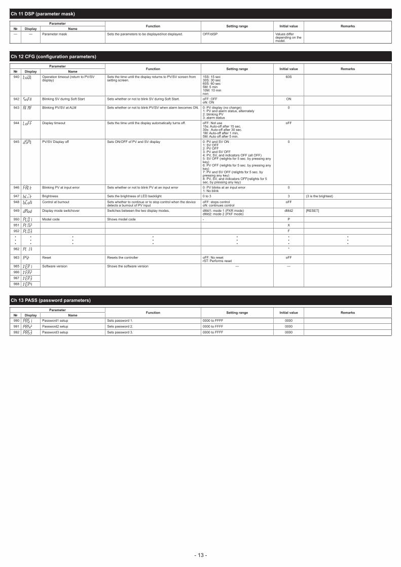
7. Functions
This controller has six types of temperature control function. Select according to type and use.
Caution The ramp soak function ( page 15), and SV selection function ( page 17) cannot be combined.
Temperature Control FunctionsON/OFF (2-position) control
Turns the control output ON/OFF according to the size relationship of PV and SV Can build a control system out of simple elements such as SSR. Suitable when accuracy is not requested.
7-1 (page 14)
PID Controls PID calculation and controls proceed according to the previously set PID parameters.PID parameters can be set manually or through auto- tuning (AT). It is the most basic control in this equipment.
7-2 (page 14)
Fuzzy PID Control PID control with function that reduces the amount of overshoot during control. It is effective when you want to suppress overshoot when SV is changed, even if you may take a long time to reach the target value.
7-3 (page 14)
Self-tuning Control Automatically calculating PID control according to the control target or SV change. It is effective when the control conditions change frequently.
7-4 (page 14)
PID2 Control In case which the power supply of the control target goes ON → OFF → ON, this PID2 control can suppress the amount of overshoot during control target turns OFF→ ON.
7-5 (page 15)
2-degrees-of-freedom control
Suppresses the amount of overshoot during PID control. It uses SV filter which is effective in reducing overshoot after a SV change or at startup.
7-6 (page 15)
7-1. ON/OFF (2-position) ControlActs as an ON/OFF control when " " = (" ").ON/OFF control switches the control output to ON (100%) or OFF (0%) according to the size relationship of PV and SV.The output hysteresis can be set under the parameter " " (" ").
Reverse Operation (heat control)
Method used to control the electrical heating furnace. Set the "hYS" to an appropriate value according to the control target.Parameter Set value
" " oNoF
" " rv--
" " arbitrary (factory setting: 1 °C)
Normal Operation (cooling control)Method used to control the cooling machineParameter Set value
" " oNoF
" " no--
" " arbitrary (factory setting: 1 °C)
Point
During ON/OFF control, the P, I and D settings do not affect control. The manual operation during ON/OFF control will become MV=100% when the
key is pressed, and MV=0% when the key is pressed. If the hysteresis width is narrow, and PV and SV are nearly equal, the output may
frequently switch ON and OFF. Note that it may affect the operation life of the contact output.
7-2. PID ControlsPID controls run as long as the parameter is set to " " = (" "). The PID controls calculate PID based on the set values for parameters " ", " ", " ", and " ", and output the calculated result (-5% to 105%).Each parameter can be set either by manually tuning the values or by running auto-tuning (AT) to automatically set the values.
Refer to
For more details on auto-tuning, see "7-7 Auto-tuning" (page 15)
Display the system menu (" ").
Display the control parameter (" ") and choose PID controls (" ").
Press the key to set the value.
PV
ON
OFFcontrol output
t
SV
process value
PV<SV
PV>SV
HYS
PV<SV
PV>SV
PV
ON
OFFcontrol output
t
SV
process valueHYS
7-3. Fuzzy PID ControlRelated to normal PID controls, fuzzy PID control acts with small overshoot.You will need to run auto-tuning to set the PID parameter when using fuzzy control.
Setting fuzzy PID control
Display the system menu (" ").
Display the control parameter (" ") and choose fuzzy (" ").
Press the key to set the value.
Refer to
For more details on auto-tuning, see "7-7 Auto-tuning" (page 15)
7-4. Self-tuning ControlSelf-tuning Control is a control which automatically calculates the value of PID, under the condition that the control target or set value (SV) changes.Self-tuning is especially effective for situations when a high level of control is not needed, but auto-tuning cannot be run due to frequent changes in the control target conditions.
Point When a high level of control is required, choose PID control, fuzzy PID control, or PID2 control.
Conditions where self-tuning can be usedSelf-tuning is used in the following situations: When temperature rises when the power is turned on When temperature rises when SV changes (or when the controller decides it is necessary) When the controller decides it is necessary because the controls have become unstable
Conditions where self-tuning cannot be usedSelf-tuning cannot be used in the following situations: During control standby During auto-tuning During ramp soak progress When there is error input When set for dual output When any of the P, I, D, Ar parameters are set to manual During manual mode During soft start progress
Conditions to halt self-tuningHalt self-tuning in the following situations: When there is a change in SV (This includes the case where SV changes because of the ramp
soak function, remote SV function, or ramp SV.) When self-tuning has not finished after running for nine or more hours
Setting self-tuning
Turn on power of the controller and set the SV.
Display the system menu (" ").
Display the controller parameter (" ") and choose self-tuning (" ").
Press the key to set the value.
Turn off power of the controller.
Turn on power of the control target equipment and the controller. Turn on power of the control equipment first. Self-tuning will begin.
dead time t
process value
tuning
SV
lag time
Point The equipment will not tune correctly if power of the controller is turned on first. To reset self-tuning, set the control method to PID (" ") once before changing back to
self-tuning.
- 14 - - 15 -
12
3
123
4
5
6
12
3

7-5. PID2 ControlIn the case which the power supply of the control target goes ON → OFF → ON, this PID2 control can suppress the amount of overshoot.This control introduces an algorithm to prevent the calculated PID result from becoming a miscalculation, even when the control loop is open.You will need to run auto-tuning to set the PID parameter when using PID2 control.
Features of PID2 Control
suppress overshoot
ON
OFFcontrol equipment power
t
SV
process value
control loop close close
open
PV
Setting PID2 control
Display the system menu (" ").
Display the control parameter (" ") and choose PID2 (" ").
Press the key to set the value.
7-6. 2-Degrees-of-Freedom PID ControlSuppresses the amount of overshoot during PID control. It uses the SV filter which is effective in reducing overshoot after a SV change or at startup.Controllability in 2-degrees-of-freedom PID control is different depending on the setting of the coefficient α and β.When the coefficient α = 100.0% and coefficient β =0.0% , the system performs the normal PID control.You can adjust the coefficient α and β as follows:
1) Set the coefficient α to 40.0% and β to 100.0%. (factory default setting)2) Perform a control to check the response (small overshoot).
If overshoot is not reduced by this measure, adjust the coefficient α and β in accordance with the following table.We recommend you to fix the coefficient α to 40.0% because it usually requires no adjustment.
Control result Coefficient β coefficient αLarge overshoot Raise coefficient β by 20% Lower coefficient α by10%Small overshoot Lower coefficient β by 20% Raise coefficient α by10%
Setting 2-degrees-of-freedom PID control
Display the system menu (" ").
Display the control parameter (" ") and choose 2-degrees-of-freedom PID (" ").
Press the key to set the value.
7-7. Auto-tuningRun auto-tuning to set the PID parameter automatically.
" " set value Behavior Function
" " Stop/Finish Stops or finishes auto-tuning.
" " Normal type The standard auto-tuning for SV reference. Choose this auto-tuning in most situations.
" " Low PV type Auto-tuning for SV-10% reference. Choose this when you want to suppress the overshoot when tuning.
PV
t
processvalue AT start
AT calculating
PID control
SVSV-10%FS
PV
t
processvalue
AT startAT calculating
PID control
SV
Normal type Low PV type
PointSet the following parameters before running auto-tuning. PV input type / PV input upper limit / PV input lower limit / Decimal position / PV input
filter in the setup channel menu (" ") OUT1 proportion cycle (OUT2 proportion cycle) in the PID channel menu (" ").
Running auto-tuning
Display auto-tuning (" ") and choose the tuning type.Choose the standard type (" ") or low PV type (" ") according to the control target
Press the key to start auto-tuning.AT lamp point will blink at the bottom of the display during auto-tuning.When auto-tuning has successfully completed, blinking AT lamp will turn off and overwrites the PID.
Point
PID parameter which is set after auto tuning has finished normally will be maintained even when the power is turned off. However, the PID value will not be
changed if the power is turned off during auto- tuning. In this case, rerun auto-tuning. The equipment will use ON/OFF (2 position) control during auto- tuning, so there may
be a large change in PV according to the process. Do not use auto-tuning for processes that do not permit a large change in PV. Do not use auto-tuning for processes such as pressure control and flow control that have a fast response.
Auto-tuning is not behaving normally if it has not finished after four or more hours have passed. In these cases, recheck parameters such as input/output wiring, control output behavior (normal/ reverse), and input sensor type.
Rerun auto-tuning if there is a large change in SV, a change in the PV input type, or a change in the control target conditions that reduces the effectiveness of the controls.
You can run auto-tuning when the control type is set to "fuzzy" or "PID2". You cannot run auto-tuning in manual mode. When using the PID selection function, the auto-tuning result for the selected PID group
is stored. Auto tuning is forcibly terminated when SV changes because of the ramp soak function,
remote SV function, or ramp SV.
7-8. Manual OutputAllows the control output to be manually set at an arbitrary value. Manual Mode Display MV indiator lights during manual mode and during parameter setting.
Switchover between Auto and Manual Modes can be changed by three methods: the front key (user key), communication function, or the
parameter " ".
MV output flow diagram (MV output priority processing)
MV MV1
MV2
MV1MV2
MV limitPID calculation
output setting during FALT
Soft start limit
Specify standby MV output
manual MV output
parameter “MAN”
Dual calculation
OFF
ON
Caution MV limit does not apply to the MV output during manual operation, FALT, or standby. (Take extra caution when MV performs flash protection during combustion control by
using the overlimit function.)
7-9. Ramp Soak FunctionAutomatically runs after setting the times for the SV changes.You can choose up to 64 steps for the SV setting and 15 types of ramp soak operation patterns.
SV-1
SV-2
SV-3SV-4
SV-5
SV-7SV-8
timeTM1r
PVTM1s
TM5rTM5s TM16r
TM16s• • • • • • • • • • • • • • • • • • • • • • • • • • • • • • • •
step1 to 4: pattern0
SV-9
SV-10SV-12
SV-13
SV-14
SV-15
SV-16
SV-11
SV-6
• • • •
step5 to 8: pattern1 step9 to 12: pattern3 step13 to 16: pattern4
step1 to 8: pattern2 step9 to 16: pattern5
step1 to 16: pattern6
SV
step1
step2 step3
Caution
When using the system in the restore mode (" ") = continue (" ") in the ramp/soak menu (" "), do not set the ramp/soak control command (" ") of the operation menu to hold (" ") during the ramp period at the beginning of the pattern.
When PV start (" ") of the ramp/soak menu (" ") is on (" "), set the pattern parameter (" ") of ramp/soak (" ") to " " = 0, 2, 6 (setting that starts with 1 seg ramp).
Do not set the Startup mode (" ") = standby mode (" ") of the sys- tem menu (" ") and the restore mode (" ") = continue (" ") of the ramp/soak menu (" ") at the same time.
- 14 - - 15 -
12
3
12
3
1
2

Creating a ramp soak operation patternSet the following items to create a pattern.
PatternSets which steps to use from the following 15 types.Steps 1 to 8 / Steps 9 to 16 / Steps 17 to 24 / Steps 25 to 32 / Steps 33 to 40 / Steps 41 to 48 / Steps 49 to 56/ Steps 57 to 64 / Steps1 to 16 / Steps 17 to 32 / Steps 33 to 48 / Steps 49 to 64 / Steps 1 to 32 / Steps 33 to 64/ Steps 1 to 64
Target SV Sets the controlled temperature.Ramp time Sets the time to reach the target SV from the current SV.Soak time Sets the time to maintain the specified SV.
The following steps will explain how to run the specified pattern 0 in SV-1 to SV-8.
Display the ramp soak menu (" ").
Display pattern parameter (" ") and choose pattern 0 (" ").Run SV-1 through SV-8.
Display the time parameter (" ") and choose minute:second (" ").Sets the units of time. Besides minute:second (" "), you can also choose hour:minute (" ")
Display the target value (" ") and set the target temperature.
Display the ramp time parameter (" ") and set the ramp time.
Display the soak time parameter (" ") and set the soak time.
Repeat steps 4 through 7 and set the remaining parameters.
Running ramp soakThe following steps explain how to run ramp soak.
Display program parameter (" ") and choose RUN (" ").
Ramp soak starts running from the current PV.
Point To interrupt the ramp soak operation, choose HOLD (" ") in step 2. To cancel the
interruption, choose RUN (" ") again. " " will display when ramp soak has completed.
Guaranty soakThis function guarantees the soak time. Only soak time within the specified range of temperature for SV is counted towards soak time.As seen in the figure below, only the sum of the shaded areas is counted as soak time. The operation moves onto the next step when the total soak time equals the specified soak time.
PVSV
process value soak time=T1+T2+T3
guaranty soak range upper limit
guaranty soak range lower limit
t
T3T2T1
The following steps will explain how to set an example guaranty soak range with an upper limit of 5°C and a lower limit of 3°C.
Display the ramp soak menu (" ").
Display guaranty ON/OFF parameter (" ") and choose on (" ").
Display the guaranty soak lower limit parameter (" ") and set the lower limit (in this example, set it to 3°C).
Display the guaranty soak upper limit parameter (" ") and set the upper limit (in this example, set it to 5°C).
Press the key to set the value.
Mode settingSets how you want to run ramp soak.
The following items can be set.Power On Start Ramp Soak starts running from the current PV.Ending Output Shows the ending output after ramp soak has been completed.OFF Output Shows the output during OFF after ramp soak has been completed.Repeat Behavior After finishing the last step in ramp soak, the process starts again from 1st step.
Setting Power On Start Ending Output OFF Output Repeat Behavior“0” Off Continuous control Continuous control Off“1” Off Continuous control Continuous control On“2” Off Continuous control Standby Off“3” Off Continuous control Standby On“4” Off Standby Continuous control Off“5” Off Standby Continuous control On“6” Off Standby Standby Off“7” Off Standby Standby On“8” On Continuous control Continuous control Off“9” On Continuous control Continuous control On“10” On Continuous control Standby Off“11” On Continuous control Standby On“12” On Standby Continuous control Off“13” On Standby Continuous control On“14” On Standby Standby Off“15” On Standby Standby On
PV startWhen the ramp soak starts (RUN), this function searches the first point where the measurement value (PV) and the program pattern match, and starts operation at that point.
Start of (3)
PV=(1)
PV=(2)
PV=(3)
Start of (2) Start of (1)
SV
If the measurement value does not match the pattern as with PV = (3), the normal operation starts.
7-10. Other Functions
1. Soft start functionWhen turning on the equipment (including the temperature controller), the soft start function suppresses the MV to become maximum output. It places an upper limit on MV output for a specified amount of time after power is turned on.This function is useful for effects such as suppressing the heater output during equipment startup, and makes load lightened.After the specified time has passed after switching on the equipment (or if SFTM = 0), the soft start function ends and normal controls begin.
Display Parameter Function
" " (SFo1) MV1 soft start output set value Places a limit on MV1 output after power is turned on for a time period set in SFTM.
" " (SFTM) Soft start set time Sets the time for soft start to function after turning power on. Setting "0" will turn off soft start.
t
control output (MV)
soft start set time
soft start output set value
MV when not using soft start
MV when using soft start (limited)
power on
0%
Caution The soft start function cannot be used simultaneously with the dual control
Point During manual mode, the manual output value has priority, but soft start will continue to keep track of the set time period.
Use the following steps to set soft start output set value and set time.
Display the setup menu (" ").
Display the setup menu (" ").
Display soft start set time (" ") and set the time.
Press the key to set the value.
Turn off the power once, and then re-start the controller to begin soft start. (When the soft start function is turned on, the lower display will alternate showing SoFT and SV.)
Note: Do not use auto-tuning at the same time.
PV
SV-1
SV-2
SV-3
SV-4
1st ramppower on start
repeats
TM1r TM1S TM2r TM2S TM3r TM3S TM4r TM4S
2nd ramp
4th ramp
3rd ramp
2nd soak
3rd soak
4th soak
1st soakYou can choose from the following 16 types of modes according to the combination of run method options.
- 16 - - 17 -
12
3
4567
12
123
4
5
123
4
5

2. Error output functionWhen the error output specification function has concluded that the equipment has an error, it halts the temperature controls and maintains the control output at a previously specified value. There is an error in PV if any of the following conditions occur:Burnout upper limit / burnout lower limit / underage (PV< -5% FS) / overage (105% <PV)
Use the following steps to set this function.
Display the setup menu (" ").
Display FALT output 1 set value (" ") and set the output value.For dual control, set " " the same way.
Press the key to set the value.
3. Standby output functionSets the control output value and the alarm output for standby mode.
Use the following steps to set this function.
Display the setup menu (" ").
Display the standby mode setting (" ") and set the alarm output for standby mode.
Refer to
For the combinations of ON/OFF settings, see "CH6 Setup parameters" (page 11).
Display the standby control output 1 set value (" ") and set the output value. For dual control, set "Sbo2" the same way.
Press the key to set the value.
4. Ramp SV functionThe ramp SV function suppresses a sudden change in SV (step change) when changing SV.It allows SV to change smoothly according to the set slope of temperature per unit of time. This smooth SV change allows you to minimize the effect of the change on controls.You can set both inclining temperature and declining temperature slopes, and choose from "minutes" or "hours" for the time units.You can also choose for the SV display to show the current value or the target value during ramp SV.
t
SV during ramp SV behavior (rMPL/rMPH)
SV changing SV with the front keyset value after change
set value before change
The SV lamp will blink while ramp SV is running.(When not displaying parameters or Ch.) When you turn on the power while ramp SV is in effect, ramp SV will begin using the starting value of PV (PV start)
t
PVpower ON
SV
SV
behavior when power risest
Sv switches to Sv-1 with DI input
SV
SV
Sv
Sv-1
behavior when SV changes with DI
Use the following steps to set this function.
Display the system menu (" ")
Set both ramp SV decline (" ") and incline (" ").
Set the unit of time for the slope (" ") during ramp SV.
Press the key to set the value.
Point Ramp SV can be used with remote SV or SV selection functions. Ramp SV cannot be used at the same time with ramp soak. Coming out of a standby state will begin PV start. Make sure to check the controller’s parameters after changing PV scale.
Caution
If the power is turned on during the input error, or released standby, the ramp SV operates differently from the normal PV start.
State at PV start Operation
Standby PV tracking (Maintains the state where SV=PV. The SV ramp function does not operate.)
Auto or manual Starts the ramp SV from the current SV (PV start is off)
5. SV selection functionThe SV selection function can record and switch up to eight sets of SV information to the palette menu settings. It is effective when the SV used during a process are numerous and the set values have been previously decided.
Use the following steps to save SV information.
Display the palette menu (" ")
Display SV setting 1 (" ") and set SV1.
Set SV setting 2 through SV setting 7 in the same way as necessary.
Press the key to set the value.
The following four methods can switch SV.• Parameter “ ” / press the user key / DI function / overwrite parameter “ ” via the
communication function
Switch Using Parameter " "
Display the operation control mode.
Display the selected SV number (" ") and choose the SV No.
Press the key to set the value.
Switch Using the User Key
Display the palette menu (" ")
Display max selected SV number (" ") and set the SV number by choosing it with the user key.
Display the user key function setting (" ") and set it to SV selection function.
On the PV/SV display, pressing the user key will switch you from the currently selected SV to the next SV.
Switch Using Parameter “ ” via the Communication Function• In the communication, overwrite the set value to the selected SV number (" ").
6. PID selection function
PointWhen switching the normal and reverse operation by using the PID selection function, be sure to turn off the system power beforehand for safety reasons (Do not switch normal and reverse operation during control).
The SV selection function can record and switch up to eight sets of PID parameters from the palette menu settings.It is effective when the control equipment changes the target often and must frequently change the PID parameters.
Use the following steps to save PID information.
Display the palette menu (" ")
Display proportional bandwidth setting 1 (" ") and set P1.
Set " " and " " in the same way.Set the following parameters as necessary: ON/OFF control hysteresis (" "), cooling proportional band (" "), dead band (" "), balance (" "), anti-reset windup (" "), and normal/reverse setting (" ")
Press the key to set the value.
The PID parameter selection (P, i, d, normal and reverse settings) can be changed by the same four methods as the SV selection function.
Switch Using Parameter “ ”
Display the operation control mode.
Display the selected PID number (" ") and choose the PID No.
Press the key to set the value.
Switch Using the User Key
Display the palette menu (" ")
Display max selected PID number (" ") and set the PID number by choosing it with the user key.
Display the user key function setting (" ") and set it to SV selection function.
On the PV/SV display, pressing the user key will switch you from the currently selected SV to the next SV.
- 16 - - 17 -
12
3
4
1
23
123
4
123
4
12
3
1
2
3
4
123
4
12
3
12
3
4

Point
When the user key function code is 27 (SV No.+1, PID No.+1 (send)) and the initial PID No. and SV No. are different, the first time you press the user key, PID No. will become the same as SV No.Also the SVMX parameter value becomes the maximum selectable number for PID No. and SV No.
Switch Using Parameter “ ” via the Communication Channel• In the communication, overwrite the set value to the selected SV number (" ").
7. Startup mode functionThe startup mode specification function sets the controller to start up in any of auto mode, manual mode, remote mode or standby mode.It is used when you want to start up in manual mode.
Use the following steps to set this function.
Display the system menu (" ")
Display the startup mode (" ") and choose the operational mode.Choose from auto or manual.
Press the key to set the value.After changing the above setting, restarting the controller will start it in the selected mode.
Point When starting up in manual, the MV becomes 0%.
8. User function key
Pressing the key in the parameter screen will immediately return you to the PV/SV display, regardless of assigned function. Holding the key, key + key, or key + key down for about a second in PV/SV display or PV/MV display will run the assigned function.
Refer to
For functions that can be assigned, see "12 USER key assignment" (page 21).
Use the following steps to set this function.
Display the system menu (" ")
Display the assign user key specification (" ") and choose the function.
Press the key to set the value.
9. bAL and Ar functions The anti-reset windup function (" ") cuts integration that falls outside of the Ar set range that is
centered around SV. Running auto-tuning will set the optimum values for P, i, and d parameters, as well as Ar.
PV
SV
cuts integration
includes integration
cuts integration
PV
AR valueAR value
The output convergence value function ("bAL") outputs to PV and SV a calculated result of the PID computed MV plus the bAL offset.
(The factory setting of bAL is 0% for single output, 50% for dual output.)
proportional bandwidth
MV
bAL=40%
50%
PVSV
40%
bAL=0%
100%
Point Ar1 to Ar7 and bAL1 to bAL7 have the same function as in each PID group.
10. MV limit functionsThe MV limit function allows you to choose whether to limit the MV or let it pass through maxi- mum and minimum MV.
PHC
PLC
103%
output value(before limit)
PHCPLC
limit
pass
limit
pass
–3%
output value(after limit)
8. Setting the Temperature Controller
8-1. Input SettingSet the type and the range for input sensor. Input can be set in the setup menu (" "].For more on input types, input scaling, decimal point location, and input codes, see "10 Input Range and Codes (standard range)". (page 19)
1. Choose an input type (" ")Check the type of the thermocouple or resistance bulb which is used.
2. Set the PV scaling (input range) (" "/" ")Set Pvb to the lower limit of the temperature range and PvF to the upper limit. It is recommendedto set the values at the standard range, even though they can be set at values beyond of it.There is no standard range for DC voltage or DC current input. (-1999 to 9999, lower limit<upper limit)
3. Set the decimal point location (" ")Sets whether or not to display digits after the decimal point. Two digits can also be dis-played after the decimal point when using 1 to 5V DC, and 4 to 20mA DC.
Point PV scaling and decimal point location can be used with the factory settings.
8-2. Output SettingSets the control output. (Only when the output is current or voltage.)
1. Sets the range of the control output (OUT1, OUT2) (" " ")"Choose any of 0 to 5V, 1 to 5V, 0 to 10V, 2 to 10V, 0 to 20mA or 4 to 20mA DC.
8-3. Control SettingSets controls to normal operation or reverse operation. Reverse operation: As the process value (PV) rises, the control output (MV) becomes smaller. Used
to heat the control object. Normal operation: As the process value (PV) rises, the control output (MV) becomes larger. Used to
cool the control object.
1. Set the normal or reverse operation (" ")Choose any of the following combinations of heat and cool to suit your system.
rEv Control output 1
Control output 2
rv-- Reverse –no-- Normal –rvno Reverse Normalnorv Normal Reverservrv Reverse Reversenono Normal Normal
9. Error Indications
9-1. Display During Equipment ErrorThis controller has a display function to indicate several types of error code shown below. If any of the error code is displayed, please eliminate the cause of error immediately. After the cause is eliminated, turn off the power once, and then re-start the controller.
Display Possible cause Control output
" "(1) Thermocouple burnout. (2) Resistance bulb sensor (A) burnout. (3)PV exceeds upper limit of the range
by 5%FS.Output as setting value when an error occurs (set in parameter Flo1 orFlo2)
" "
(1) Resistance bulb sensor B or C wire burnout.
(2) Resistance bulb sensor (between A & B or A & C) short.
(3) PV is below lower limit of the range by 5%FS.
(4) Burnout or short in the voltage input.
" " (1) PV < -199.9
Control operation is continuedNote) Control operation is continued
as long as the accuracy is above -5%FS.When the accuracy declines to be lower than -5%FS, the controller outputs the specified value for an error.
" " (SV flickers) Incorrect setting (Pvb/PvF)The controller outputs the specified value for an error. (The value can be set in parameter Flo1 or Flo2)
PV is not displayed Check the set value of DSPT.Normal control* The controller does not have to be
restarted
SV is not displayed Check the set value of DSPT.Normal control* The controller does not have to be
restarted
Parameters may not be displayed Check the settings of Ch11 DSPNormal control* The controller does not have to be
restarted
PCUTMV1 MV2
PHC1 PLC1 PHC2 PLC2"0" "1""2""3"
103%103%limit limit
-3%limit-3%limit
103%103%103%103%
-3%-3%-3%-3%
"4""5""6""7"
103%103%limitlimit
-3%limit-3%limit
103%103%103%103%
limitlimitlimitlimit
"8""9""10""11"
103%103%limitlimit
-3%limit-3%limit
limitlimitlimitlimit
-3%-3%-3%-3%
"12""13""14""15"
103%103%limitlimit
-3%limit-3%limit
limitlimitlimitlimit
limitlimitlimitlimit
- 18 - - 19 -
1
2
3
12
3

10. Input Range and Codes (standard range)
Input type Input code(PVT)
Measurementrange
(°C) (PVb, PVF)
Minimuminput
increment(°C)
Measurementrange
(°F) (PVb, PVF)
Minimuminput
increment(°F)
RTDJIS (IEC)
JPt 100 JPT1 0.0 to 150.0 0.1 32.0 to 302.0 0.1JPT2 0.0 to 300.0 0.1 32.0 to 572.0 0.1JPT3 0.0 to 500.0 0.1 32.0 to 932.0 0.1JPT4 0.0 to 600.0 0.1 32 to 1112 1JPT5 -50.0 to 100.0 0.1 -58.0 to 212.0 0.1JPT6 -100.0 to 200.0 0.1 -148.0 to 392.0 0.1JPT7 -199.9 to 600.0 0.1 -328 to 1112 1
Pt 100 PT1 0.0 to 150.0 0.1 32.0 to 302.0 0.1PT2 0.0 to 300.0 0.1 32.0 to 572.0 0.1PT3 0.0 to 500.0 0.1 32.0 to 932.0 0.1PT4 0.0 to 600.0 0.1 32 to 1112 1PT5 -50.0 to 100.0 0.1 -58.0 to 212.0 0.1PT6 -100.0 to 200.0 0.1 -148.0 to 392.0 0.1PT7 -199.9 to 600.0 0.1 -328 to 1112 1PT8 -200 to 850 1 -328 to 1562 1
Thermocouple J J1 0.0 to 400.0 0.1 32.0 to 752.0 0.1J2 -20.0 to 400.0 0.1 -4.0 to 752.0 0.1J3 0.0 to 800.0 0.1 32 to 1472 1J4 -100 to 1000 1 -148 to 1832 1
K K1 0 to 400 0.1 32 to 752 0.1K2 -20.0 to 500.0 0.1 -4.0 to 932.0 0.1K3 0.0 to 800.0 0.1 32 to 1472 1K4 -200 to 1300 1 -328 to 2372 1
R R 0 to 1700 1 32 to 3092 1B B 0 to 1800 1 32 to 3272 1S S 0 to 1700 1 32 to 3092 1T T1 -199.9 to 200.0 0.1 -199.9 to 392.0 0.1
T2 -199.9 to 400.0 0.1 -199.9 to 752.0 0.1E E1 0.0 to 800.0 0.1 32 to 1472 1
E2 -150.0 to 800.0 0.1 -238 to 1472 1E3 -200 to 800 1 -328 to 1472 1
L L -100 to 850 1 -148 to 1562 1U U1 -199.9 to 400.0 0.1 -199.9 to 752.0 0.1
U2 -200 to 400 1 -328 to 752 1N N -200 to 1300 1 -328 to 2372 1W W 0 to 2300 1 32 to 4172 1
PL-II PL-2 0 to 1300 1 32 to 2372 1DC voltage 0 to 5 V DC 0-5V
-1999 to 9999(Range where
scaling is allowed)—
-1999 to 9999(Range where
scaling is allowed)—
1 to 5 V DC 1-5V0 to 10V DC 0-102 to 10V DC 2-10
0 to 100mV DC MVDC current 0 to 20 mA DC 0-20
4 to 20 mA DC 4-20
11. Alarm Action Type Codes
Type A1Tp to A5Tp Alarm Type Action diagram0 No alarm —
Absolute value alarm 1 High alarm PV
t
ALn
2 Low alarm PV
tALn
3 High alarm (with hold) PV
t
ALn
4 Low alarm (with hold) PV
tALn
Deviation alarm 5 High alarm
SV
PV
tALn
6 Low alarmSVPV
tALn
7 High/Low alarm
SV
PVALn
t
8 High alarm (with hold)
SV
PV
tALn
9 Low alarm (with hold)SVPV
tALn
10 High/Low alarm (with hold)
SV
PVALn
t
Zone alarm 11 High/Low deviation alarm
SV
PV
t
ALnL
Dual Set Value Alarm Codes Type A1Tp to A5Tp Alarm Type Action diagramHigh/Low limit alarm 16 High/Low absolute alarm PV
t
ALnhALnL
17 High/Low deviation alarm
SV
PV
t
ALnhALnL
18 High absolute/Low deviation alarm
SV
PV
t
ALnhALnL
19 High deviation/Low absolute alarm
SV
PV
t
ALnhALnL
20 High/Low absolute alarm (with hold)
PV
t
ALnLALnL
21 High/Low deviation alarm (with hold)
SV
PV
t
ALnhALnL
22 High absolute/Low deviation alarm (with hold)
SV
PV
t
ALnhALnL
23 High deviation/Low absolute alarm (with hold)
SV
PV
t
ALnhALnL
Zone alarm 24 High/Low absolute alarm PV
t
ALnh
ALnL
25 High/Low deviation alarm
SV
PV
t
ALnhALnL
26 High absolute/Low deviation alarm
SV
PV
tALnLALnh
27 High deviation/Low absolute alarm
SV
PV
tALnLALnh
28 High/Low absolute alarm (with hold)
PV
t
ALnh
ALnL
29 High/Low deviation alarm (with hold)
SV
PV
t
ALnhALnL
30 High absolute/Low deviation alarm (with hold)
SV
PV
tALnLALnh
31 High deviation/Low absolute alarm (with hold)
SV
PV
tALnLALnh
Timer Code, otherType A1Tp to A5Tp Alarm Type Action diagramTimer 32
ON delay timerDI
ALMdLYn
33
OFF delay timerDI
ALMdLYn
34
ON/OFF delay timerDI
ALMdLYn dLYn
Ramp soak delay start 35 Delay start ONOpen circuit and short circuit 37 Open loop alarm
38 H e a t e r b u r n o u t a l a r m (Optional CT is required)
41 Shorted load alarm (Optional CT is required)
Power 45 Amount of electric energyMaintenance 46 Preventive maintenance.
The number of times that the relay has operated (MV1, MV2)
47 Preventive maintenance. Operated hours
Point
What is alarm with hold?The alarm will not turn ON immediately when the process value gets into the alarm band and enters again. If without hold, alarm may turn ON when starting up.
PV (process value)
power on
lower limit alarm
lower limit alarm (with hold)
power onpower off
Lower limit alarm output area
off off offon on
off offon
- 18 - - 19 -

Caution
When alarm action code is changed, alarm set value may also become different from previous settings.
When alarm action type code is changed, turn off the power once, and then re-start the controller, before starting control.
Aln: AL1 to AL5 show the alarm set values ALnh: AL1h to AL5h show the alarm set values ALnL: AL1L to AL5L show the alarm set values dLYn: dLY1 to dLY5 show the alarm delay on set values
* Other than the alarm setting, each of the event output functions can be assigned to DO1 to 5. For more details on each of the event output functions, refer to "13. OUT, DO, indicators assignment" (page 21).
12. USER key assignment
UkY 1 to 3 set value Key function
0 No function
1 Switchover between STBY ON/OFF
2 Switchover between Auto/Manual
3 Switchover between Locul/Remote
4 Setting unavailable
5 Starts AT (standard)
6 Starts AT (low PV)
7 Setting unavailable
8 Ramp SV HOLD
9 Ramp soak RUN/OFF
10 Ramp soak RUN/HOLD
11 Setting unavailable
12 Latch release (all)
13 Latch release (ALM1)
14 Latch release (ALM2)
15 Latch release (ALM3)
16 Latch release (ALM4)
17 Latch release (ALM5)
19 Start timer (ALM1)
20 Start timer (ALM2)
21 Start timer (ALM3)
22 Start timer (ALM4)
23 Start timer (ALM5)
25 SVNo. + 1 (send)
26 PID No. + 1 (send)
27 Setting unavailable
28 Ramp soak pattern No. + 1 (send)
29 SV No. + 1, PID No. + 1 (send)
13. OUT, Alarm output, indicators assignment
OUT(Relay/SSR)
OUT (Current/Voltage)
Alarm output Indicator
Category Function
oU1T, oU2T oU1ToU2T
do1T, do2T, do3T, do4T,
do5T
LoU1, LoU2, LEV 1 to 3,
LSTb, LMAN
0 0 0 0 None
1 1 1 1 Control output MV1 (heating)
2 2 2 2 MV2 (cooling)
3 — 3 3 Alarm output Alarm 1
4 — 4 4 Alarm 2
5 — 5 5 Alarm 3
6 — 6 6 Alarm 4
7 — 7 7 Alarm 5
10 — 10 10 Status output During auto-tuning startup
11 — 11 11 Normal
12 — 12 12 Standby
13 — 13 13 During manual mode
14 — 14 14 During remote SV operation
15 — 15 15 During ramp SV
16 — 16 16 System error
20 — 20 20 Ramp soakevent output
OFF
21 — 21 21 RUN
22 — 22 22 HOLD
23 — 23 23 GS (Guaranty soak)
24 — 24 24 END
170 — 170 170 Ramp soakTime signal
Time signal (step 1 ramp)
171 — 171 171 Time signal (step 1 soak)
172 — 172 172 Time signal (step 2 ramp)
173 — 173 173 Time signal (step 2 soak)
•••
•••
•••
•••
•••
294 — 294 294 Time signal (step 63 ramp)
295 — 295 295 Time signal (step 63 soak)
296 — 296 296 Time signal (step 64 ramp)
297 — 297 297 Time signal (step 64 soak)
300 — 300 300 Ramp soakRelative time signal
Time signal (1st step ramp)
301 — 301 301 Time signal (1st step soak)
302 — 302 302 Time signal (2nd step ramp)
303 — 303 303 Time signal (2nd step soak)
•••
•••
•••
•••
•••
424 — 424 424 Time signal (63rd step ramp)
425 — 425 425 Time signal (63rd step soak)
426 — 426 426 Time signal (64th step ramp)
427 — 427 427 Time signal (64th step soak)
- 20 - - 21 -
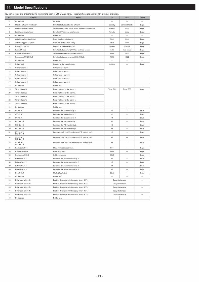
14. Model Specifications
You can allocate one of the following functions to each of DI1, DI2, and DI3. These functions are activated by external DI signals.
No. Function Action ON OFF Criteria
0 No function No action — — —
1 Standby ON/OFF switchover Switches between Standby ON/OFF. Standby Cancels Standby Edge
2 Auto/manual switchover Switches the control output action between auto/manual. Manual Auto Edge
3 Local/remote switchover Switches SV between local/remote. Remote Local Edge
4 No function Not for use. — — —
5 Auto tuning (standard) start Runs standard auto-tuning. Start Stop Edge
6 Auto tuning (low-PV) start Runs low-PV type auto-tuning. Start Stop Edge
7 Ramp SV ON/OFF Enables or disables ramp SV. Disable Enable Edge
8 Ramp SV hold Switches between ramp SV hold and hold cancel. Hold Hold cancel Edge
9 Ramp soak RUN/OFF Switches between ramp soak RUN/OFF. RUN OFF Edge
10 Ramp soak RUN/HOLD Switches between ramp soak RUN/HOLD. RUN HOLD Edge
11 No function Not for use. — — —
12 Unlatch (all) Cancels all the alarm latches. Unlatch — Edge
13 Unlatch (alarm 1) Unlatches the alarm 1.
14 Unlatch (alarm 2) Unlatches the alarm 2.
15 Unlatch (alarm 3) Unlatches the alarm 3.
16 Unlatch (alarm 4) Unlatches the alarm 4.
17 Unlatch (alarm 5) Unlatches the alarm 5.
18 No function Not for use. — — —
19 Timer (alarm 1) Runs the timer for the alarm 1. Timer ON Timer OFF Level
20 Timer (alarm 2) Runs the timer for the alarm 2.
21 Timer (alarm 3) Runs the timer for the alarm 3.
22 Timer (alarm 4) Runs the timer for the alarm 4.
23 Timer (alarm 5) Runs the timer for the alarm 5.
24 No function Not for use. — — —
25 SV No. + 1 Increases the SV number by 1. +1 — Level
26 SV No. + 2 Increases the SV number by 2. +2 — Level
27 SV No. + 4 Increases the SV number by 4. +4 — Level
28 PID No. + 1 Increases the PID number by 1. +1 — Level
29 PID No. + 2 Increases the PID number by 2. +2 — Level
30 PID No. + 4 Increases the PID number by 4. +4 — Level
31 SV No. + 1, PID No. + 1
Increases both the SV number and PID number by 1. +1 — Level
32 SV No. + 2, PID No. + 2
Increases both the SV number and PID number by 2. +2 — Level
33 SV No. + 4, PID No. + 4
Increases both the SV number and PID number by 4. +4 — Level
34 Ramp soak OFF Stops ramp soak operation. OFF — Edge
35 Ramp soak RUN Runs ramp soak. RUN — Edge
36 Ramp soak HOLD Holds ramp soak. HOLD — Edge
37 Pattern No. + 1 Increases the pattern number by 1. +1 — Level
38 Pattern No. + 2 Increases the pattern number by 2. +2 — Level
39 Pattern No. + 4 Increases the pattern number by 4. +4 — Level
40 Pattern No. + 8 Increases the pattern number by 8. +8 — Level
41 DI soft start Starts DI soft start. Start — Edge
42 No function Not for use. — — —
43 Delay start (alarm 1) Enables delay start with the delay time = dLY1. Delay start enable —
44 Delay start (alarm 2) Enables delay start with the delay time = dLY2. Delay start enable —
45 Delay start (alarm 3) Enables delay start with the delay time = dLY3. Delay start enable —
46 Delay start (alarm 4) Enables delay start with the delay time = dLY4. Delay start enable —
47 Delay start (alarm 5) Enables delay start with the delay time = dLY5. Delay start enable —
48 No function Not for use. — — —
- 20 - - 21 -

15. Model Specifications
15-1. PXF5 & PXF9 (Standard type)
Specifications
4 5 6 7 8PXF
4
56
7
89
10
11
1213
59
A 0 02 -
A
ABCEP
YACEPRS
2
01FMJ
YVWABD
<Front panel size W × H>48 × 96 mm96 × 96 mm–<Control output 1>Relay contact (SPST)Relay contact (SPDT)SSR drive outputCurrent outputVoltage output<Control output 2>NoneRelay contact (SPST)SSR drive outputCurrent outputVoltage outputTransfer output (current)Transfer output (voltage)<Revision code><Alarm output>None1 point2 points3 points2 points (independent common)<Power supply voltage/instruction manual>100 to 240 V AC, Japanese & English 100 to 240 V AC, English 100 to 240 V AC, Chinese & English24 V AC/DC, Japanese & English24 V AC/DC, English 24 V AC/DC, Chinese & English <Option>NoneRS-485 CommunicationDigital input (DI1, DI2)Remote SV input + Digital input (DI3)CT input + Digital input (DI1)RS-485 communication + Digital input (DI1)RS-485 communication + Digital input (DI3, 4, 5) + Auxiliary alarm output (AL4, AL5)–
9 10 11 12 13
Digit Note
Note2Note1
YMTHGVC
0 0Note 1: When using the CT input as a heater burnout alarm, add one alarm output for it. (Add one point in the 9th code.)Note 2: When a current input is used, a resistance of 250 Ω is required at the input terminal.
- 22 - - 23 -

15-2. PXF5 & PXF9 (Motorized valve control type)
Specifications
4 5 6 7 8PXF
4
56
7
89
10
11
1213
59
A Y 0 02 -
A
SV
Y2
01FMJ
YVWABD
<Front panel size W × H>48 × 96 mm96 × 96 mm–<Control output 1>Motorized valve control output (without PFB input)Motorized valve control output (with PFB input)<Control output 2>None<Revision code><Alarm output>None1 point2 points3 points2 points (independent common)<Power supply voltage/instruction manual>100 to 240 V AC, Japanese & English100 to 240 V AC, English100 to 240 V AC, Chinese & English 24 V AC/DC, Japanese & English 24 V AC/DC, English 24 V AC/DC, Chinese & English <Option>NoneRS-485 communication + Digital input (DI1, 2, 3)–
9 10 11 12 13
Digit Note
YU
0 0
- 22 - - 23 -
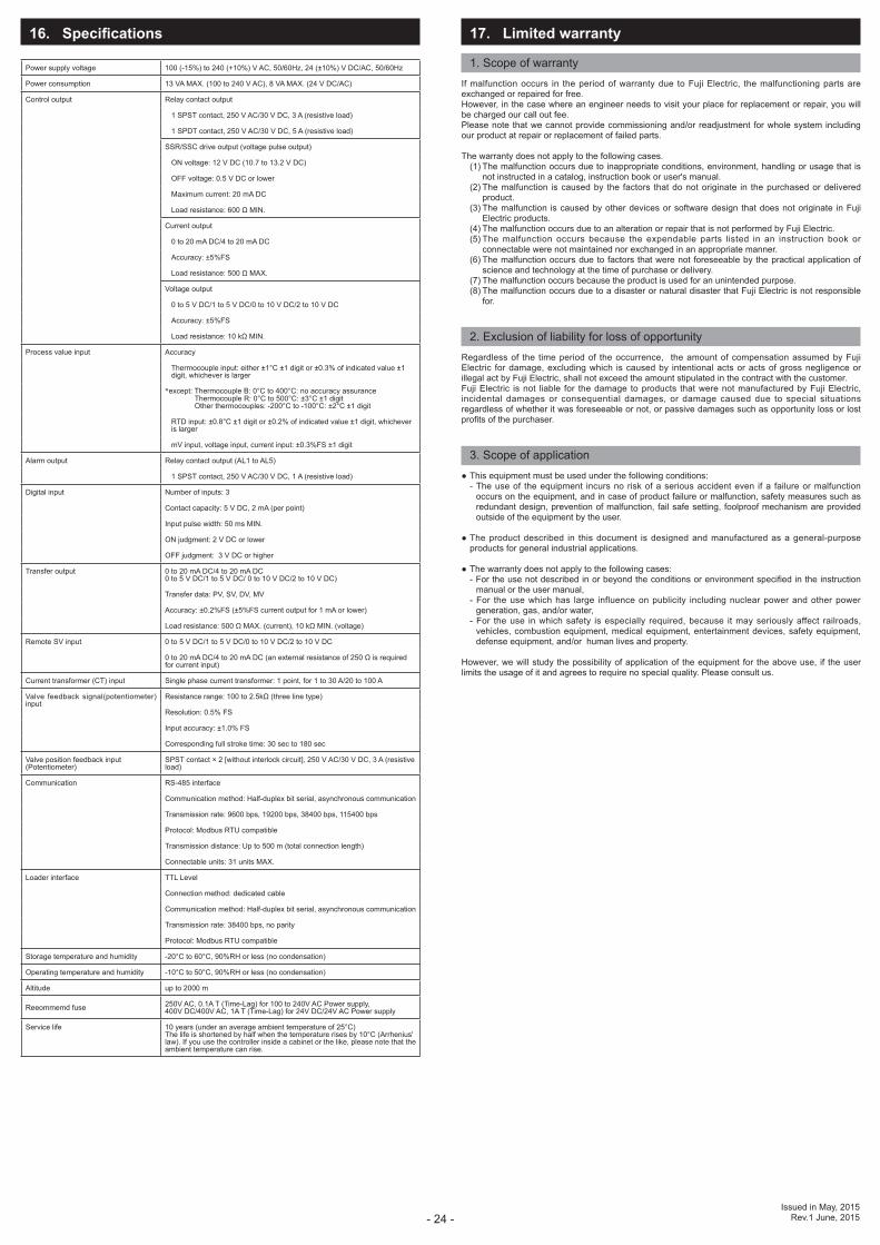
16. Specifications
Power supply voltage 100 (-15%) to 240 (+10%) V AC, 50/60Hz, 24 (±10%) V DC/AC, 50/60Hz
Power consumption 13 VA MAX. (100 to 240 V AC), 8 VA MAX. (24 V DC/AC)
Control output Relay contact output
1 SPST contact, 250 V AC/30 V DC, 3 A (resistive load)
1 SPDT contact, 250 V AC/30 V DC, 5 A (resistive load)
SSR/SSC drive output (voltage pulse output)
ON voltage: 12 V DC (10.7 to 13.2 V DC)
OFF voltage: 0.5 V DC or lower
Maximum current: 20 mA DC
Load resistance: 600 Ω MIN.
Current output
0 to 20 mA DC/4 to 20 mA DC
Accuracy: ±5%FS
Load resistance: 500 Ω MAX.
Voltage output
0 to 5 V DC/1 to 5 V DC/0 to 10 V DC/2 to 10 V DC
Accuracy: ±5%FS
Load resistance: 10 kΩ MIN.
Process value input Accuracy
Thermocouple input: either ±1°C ±1 digit or ±0.3% of indicated value ±1 digit, whichever is larger
*except: Thermocouple B: 0°C to 400°C: no accuracy assurance Thermocouple R: 0°C to 500°C: ±3°C ±1 digit Other thermocouples: -200°C to -100°C: ±2°C ±1 digit
RTD input: ±0.8°C ±1 digit or ±0.2% of indicated value ±1 digit, whichever is larger
mV input, voltage input, current input: ±0.3%FS ±1 digit
Alarm output Relay contact output (AL1 to AL5)
1 SPST contact, 250 V AC/30 V DC, 1 A (resistive load)
Digital input Number of inputs: 3
Contact capacity: 5 V DC, 2 mA (per point)
Input pulse width: 50 ms MIN.
ON judgment: 2 V DC or lower
OFF judgment: 3 V DC or higher
Transfer output 0 to 20 mA DC/4 to 20 mA DC0 to 5 V DC/1 to 5 V DC/ 0 to 10 V DC/2 to 10 V DC)
Transfer data: PV, SV, DV, MV
Accuracy: ±0.2%FS (±5%FS current output for 1 mA or lower)
Load resistance: 500 Ω MAX. (current), 10 kΩ MIN. (voltage)
Remote SV input 0 to 5 V DC/1 to 5 V DC/0 to 10 V DC/2 to 10 V DC
0 to 20 mA DC/4 to 20 mA DC (an external resistance of 250 Ω is required for current input)
Current transformer (CT) input Single phase current transformer: 1 point, for 1 to 30 A/20 to 100 A
Valve feedback signal(potentiometer) input
Resistance range: 100 to 2.5kΩ (three line type)
Resolution: 0.5% FS
Input accuracy: ±1.0% FS
Corresponding full stroke time: 30 sec to 180 sec
Valve position feedback input (Potentiometer)
SPST contact × 2 [without interlock circuit], 250 V AC/30 V DC, 3 A (resistive load)
Communication RS-485 interface
Communication method: Half-duplex bit serial, asynchronous communication
Transmission rate: 9600 bps, 19200 bps, 38400 bps, 115400 bps
Protocol: Modbus RTU compatible
Transmission distance: Up to 500 m (total connection length)
Connectable units: 31 units MAX.
Loader interface TTL Level
Connection method: dedicated cable
Communication method: Half-duplex bit serial, asynchronous communication
Transmission rate: 38400 bps, no parity
Protocol: Modbus RTU compatible
Storage temperature and humidity -20°C to 60°C, 90%RH or less (no condensation)
Operating temperature and humidity -10°C to 50°C, 90%RH or less (no condensation)
Altitude up to 2000 m
Reeommemd fuse 250V AC, 0.1A T (Time-Lag) for 100 to 240V AC Power supply,400V DC/400V AC, 1A T (Time-Lag) for 24V DC/24V AC Power supply
Service life 10 years (under an average ambient temperature of 25°C) The life is shortened by half when the temperature rises by 10°C (Arrhenius' law). If you use the controller inside a cabinet or the like, please note that the ambient temperature can rise.
17. Limited warranty
1. Scope of warrantyIf malfunction occurs in the period of warranty due to Fuji Electric, the malfunctioning parts are exchanged or repaired for free.However, in the case where an engineer needs to visit your place for replacement or repair, you will be charged our call out fee. Please note that we cannot provide commissioning and/or readjustment for whole system including our product at repair or replacement of failed parts.
The warranty does not apply to the following cases. (1) The malfunction occurs due to inappropriate conditions, environment, handling or usage that is
not instructed in a catalog, instruction book or user's manual. (2) The malfunction is caused by the factors that do not originate in the purchased or delivered
product. (3) The malfunction is caused by other devices or software design that does not originate in Fuji
Electric products. (4) The malfunction occurs due to an alteration or repair that is not performed by Fuji Electric. (5) The malfunction occurs because the expendable parts listed in an instruction book or
connectable were not maintained nor exchanged in an appropriate manner. (6) The malfunction occurs due to factors that were not foreseeable by the practical application of
science and technology at the time of purchase or delivery. (7) The malfunction occurs because the product is used for an unintended purpose. (8) The malfunction occurs due to a disaster or natural disaster that Fuji Electric is not responsible
for.
2. Exclusion of liability for loss of opportunityRegardless of the time period of the occurrence, the amount of compensation assumed by Fuji Electric for damage, excluding which is caused by intentional acts or acts of gross negligence or illegal act by Fuji Electric, shall not exceed the amount stipulated in the contract with the customer.Fuji Electric is not liable for the damage to products that were not manufactured by Fuji Electric, incidental damages or consequential damages, or damage caused due to special situations regardless of whether it was foreseeable or not, or passive damages such as opportunity loss or lost profits of the purchaser.
3. Scope of application This equipment must be used under the following conditions:
- The use of the equipment incurs no risk of a serious accident even if a failure or malfunction occurs on the equipment, and in case of product failure or malfunction, safety measures such as redundant design, prevention of malfunction, fail safe setting, foolproof mechanism are provided outside of the equipment by the user.
The product described in this document is designed and manufactured as a general-purpose products for general industrial applications.
The warranty does not apply to the following cases:- For the use not described in or beyond the conditions or environment specified in the instruction
manual or the user manual,- For the use which has large influence on publicity including nuclear power and other power
generation, gas, and/or water,- For the use in which safety is especially required, because it may seriously affect railroads,
vehicles, combustion equipment, medical equipment, entertainment devices, safety equipment, defense equipment, and/or human lives and property.
However, we will study the possibility of application of the equipment for the above use, if the user limits the usage of it and agrees to require no special quality. Please consult us.
Issued in May, 2015Rev.1 June, 2015- 24 -


![Micro Exam 1 [Weston] x](https://static.fdocuments.in/doc/165x107/577d1ff81a28ab4e1e91bee7/micro-exam-1-weston-x.jpg)


